Complete Repair Service Technical Manual for John Deere Tractors 6100J, 6115J, 6125J, 6135J, 6150J, 6170J, 6190J, 6210J, with all the workshop information to maintain, repair, and rebuild like professional mechanics.
John Deere Tractors 6100J, 6115J, 6125J, 6135J, 6150J, 6170J, 6190J, 6210J workshop technical manual (repair) includes:
* Numbered table of contents easy to use so that you can find the information you need fast.
* Detailed sub-steps expand on repair procedure information
* Numbered instructions guide you through every repair procedure step by step.
* Notes, cautions and warnings throughout each chapter pinpoint critical information.
* Bold figure number help you quickly match illustrations with instructions.
* Detailed illustrations, drawings and photos guide you through every procedure.
* Enlarged inset helps you identify and examine parts in detail.
TM808719 – 6J Tractors (600000 – )—Repair Technical Manual.pdf
PRODUCT DETAILS:
Total Pages: 1,902 pages
File Format: PDF (bookmarked, ToC, Searchable, Printable)
Language: English French Portuguese Spanish
TM808719 Repair Technical Manual 6J Tractors (600001 – )—Repair Technical Manual
Language: English
Equipment Model: 6100J, 6115J, 6125J, 6135J, 6150J, 6170J, 6190J, 6210J
Serial Number: 600000-
Edition: South America
TM808728 Repair Technical Manual 6J Tractors (600001 – )—Repair Technical Manual
Language: French
TM808754 Repair Technical Manual 6J Tractors (600001 – )—Repair Technical Manual
Language: Portuguese
TM808763 Repair Technical Manual 6J Tractors (600001 – )—Repair Technical Manual
Language: Spanish
TABLE OF CONTENTS
Section 05: Safety…32
Group 05: Safety…32
Recognize Safety Information…457
Understand Signal Words…36
Follow Safety Instructions…37
Practice Safe Maintenance…38
Live With Safety…39
Handle Fluids Safely—Avoid Fires…40
Prepare for Emergencies…41
Wear Protective Clothing…42
Work in Clean Area…43
Work In Ventilated Area…44
Illuminate Work Area Safely…45
Remove Paint Before Welding or Heating…46
Avoid Heating Near Pressurized Fluid Lines…47
Use Proper Tools…48
Construct Dealer-Made Tools Safely…49
In Case of Fire…50
Avoid Harmful Asbestos Dust…51
Decommissioning — Proper Recycling and Disposal of Fluids and Components…52
Precautions for Welding…53
Park Machine Safely…55
Support Machine Properly…56
Replace Safety Signs…57
Clean Vehicle of Hazardous Pesticides…58
Handle Agricultural Chemicals Safely…59
Service Machines Safely…61
Use Proper Lifting Equipment…62
Avoid High-Pressure Fluids…63
Service Accumulator Systems Safely…64
Wait Before Opening High-Pressure Fuel System…65
Keep ROPS Installed Properly…66
Service Tires Safely…67
Avoid Static Electricity Risk When Refueling…68
Prevent Acid Burns…70
Handling Batteries Safely…72
Prevent Battery Explosions…74
Section 10: General Information…225
Group 05: References for Technical Information…75
Sealants and Adhesives Cross-Reference Chart…79
Metric Bolt and Screw Torque Values…82
Unified Inch Bolt and Screw Torque Values…84
Face Seal Fittings Assembly and Installation—All Pressure Applications…87
Metric Face Seal and O-Ring Stud End Fitting Torque Chart—Standard Pressures…88
Metric Face Seal and O-Ring Stud End Fitting Torque Chart—High Pressure Applications…90
SAE Face Seal and O-Ring Stud End Fitting Torque Chart—Standard Pressures…92
SAE Face Seal and O-Ring Stud End Fitting Torque Chart—High Pressure Applications…94
Four Bolt Flange Fittings Assembly and Installation—All Pressure Applications…96
SAE Four Bolt Flange Cap Screw Torque Values—Standard Pressure Applications…97
SAE Four Bolt Flange Cap Screw Torque Values—High Pressure Applications…98
External Hexagon Port Plug Torque Chart…99
Prevent Hydraulic System Contamination…101
Identify Zinc-Flake Coated Fasteners…102
Use Torque Wrench Adapter…103
Servicing and Connecting Snap to Connect STC™ Fittings…105
Use Special Wrench…1930
Install Hydraulic Fittings…108
Section 20: Engine…110
Group 05: Remove and Install Components…110
John Deere Engine Component Information…192
Special Tools…1845
Specifications…1856
Remove and Install 4.5L Engine…116
Remove and Install 6.8L Engine…139
Engine Mountings—Exploded View…165
Replace Engine Mountings…166
Section 30: Fuel, Air Intake, Cooling, and Exhaust System…171
Group 05: Speed Control…171
General Information…225
Specifications…1856
Other Material…1855
Mechanical Hand Throttle Lever—Exploded View…177
Mechanical Speed Control Pedal—Exploded View…179
Mechanical Hand Throttle Lever and Speed Control Pedal Adjustment…184
Mechanical Speed Control Link Adjustment…183
Speed Control Pedal Adjustment…184
Remove and Install Hand Throttle Potentiometer…185
Remove and Install Speed Control Pedal Assembly…186
Remove and Install Speed Control Pedal Potentiometer…188
Group 10: Fuel System…171
John Deere Engine Component Information…192
General information…1857
Specifications…1856
Other Material…1855
Fuel System 4.5L Engine…196
Fuel System 6.8L Engine…198
Drain Fuel Filters…200
Drain Fuel Tank…202
Remove and Install Fuel Tank…204
Remove and Install Fuel Transfer Pump…209
Remove and Install Fuel Filters…213
Bleed Fuel System…217
Restarting an Engine Which Has Run Out of Fuel…220
Group 15: Air Intake System…171
General Information…225
Specifications…1856
Engine Air Cleaner—Exploded View…227
Remove and Install Engine Air Cleaner Housing…228
Group 20: Cooling System…172
General information…1857
Specifications…1856
Remove and Install Radiator…232
Remove and Install Expansion Tank…241
Remove and Install Engine Fan…245
Remove and Install Viscous Fan Drive Clutch…250
Remove and Install Oil Cooler/Air Conditioner Condenser…252
Remove and Install Ring-Shaped Oil Cooler…254
Remove and Install Charge Air Cooler…255
Releasing Drive Belt Tension…260
Replace Engine Fan Belt…261
Remove and Install Automatic Belt Tensioner…266
Remove and Install Fan Console…267
Disassemble, Repair, and Assemble Fan Console…270
Group 25: Exhaust System…172
General information…1857
Specifications…1856
Other Materials…1669
Remove and Install Muffler…276
Remove and Install Exhaust Pipe…278
Section 40: Electrical System…283
Group 05: Harness and Connectors Repair…283
Special Tools…1845
General…289
Use of High-Pressure Washers…290
Replace SURE-SEAL® Connectors…291
Install Weather Pack™ Contact…293
Service Parts Kits…295
Replace CPC™, Large Mate-N-Lok®, and Metrimate® Pin-Type Connectors…296
Replace CPC™ Blade Type Connectors…297
Replace Small Mate-N-Lok® Socket Connector…298
Replace Small Mate-N-Lok® Pin Connector…299
Replace DEUTSCH® Connectors…300
Replace Weather Pack™ Connector…302
Replace SURE-SEAL® Connector with Weather Pack™ Connector…304
Remove Connector Body from Blade Terminals…306
Install DEUTSCH® Contact…307
Installation of Repair Wire Assembly (RWA)…309
Group 15: Charging System…283
Special Tools…1845
Specifications…1856
Replacing Alternator…321
Disconnecting Electrical Circuits…460
Remove and Install Alternator…323
Remove and Install Alternator Pulley…325
Remove and Install the Battery…327
Group 20: Starter Motor Circuit…283
Special Tools…1845
Specifications…1856
Repairing Starter Motor…332
Disconnecting Electrical Circuits…460
Remove and Install Starter Motor…334
Group 25: Fuses, Relays, and Switches…284
Special Tools…1845
Specifications…1856
Disconnecting Electrical Circuits…460
Access to the Fuses and Relays…340
Main Fuses (If Equipped)…342
Fuse Box—Tractors with Open Operator’s Station…344
Fuse Box—Tractors with Cab…346
Power Link Box (If Equipped)…348
Power Link Box Components (If Equipped)…349
Remove and Install Starter Relay…350
Remove and Install Key Switch…353
Remove and Install Brake Switch…354
Remove and Install Light Switch…355
Remove and Install High-Beam and Low-Beam Headlights Switch…356
Remove and Install Worklights Switch…357
Remove and Install Hazard Warning Light Switch…358
Remove and Install Turn-Signal Switch…359
Remove and Install Horn Switch…360
Remove and Install Windshield Wiper and Windshield Washer Switch…361
Remove and Install Front-Wheel Drive Switch…362
Remove and Install Power Take-off Switch…363
Remove and Install Load Depth Control Potentiometer—Cab Tractors…364
Remove and Install Hitch Control Unit—Cab Tractors…365
Remove and Install FieldCruise™ Control Potentiometer…366
Remove and Install Fan Switch…368
Remove and Install Differential Lock Switch—Tractors with Open Operator’s Station…369
Remove and Install Differential Lock Switch—Tractors with Cab…370
Remove and Install Hydraulic Hitch Remote Control Switch—Tractors with Cab…371
Group 30: Electrical Components…284
Note…373
Special Tools…1845
Specifications…1856
Disconnecting Electrical Circuits…460
Lights with Halogen Bulbs…377
Remove and Install Instrument Panel…379
Remove and Install Trailer Socket…382
Remove and Install Service ADVISOR™ Socket…384
Remove and Install Windshield Wiper Motor…387
Removing Windshield Washer Pump…389
Handle Halogen Light Bulbs Safely…390
Replace High and Low Beam Headlights Bulbs…391
Replace Rear Worklight Bulb—Open Operator’s Station Tractors…393
Replace Front Turn-Signal Lights, Hazard Warning Lights, and Clearance Lights Bulbs—Open Operator’s Station Tractors…395
Replace Worklight Bulbs—Cab Tractors…397
Replace Front Turn-Signal Light, and Hazard Warning Lights Bulbs—Cab Tractors…399
Replace Rear Turn-Signal Light, Hazard Warning Light, and Brake Light Bulbs…400
Replace Backup Light Bulb…402
Replace License Plate Light Bulb…404
Group 35: Monitoring Systems…285
Replace Engine Speed Sensor (B001)…407
Replace Engine Air Cleaner Restriction Pressure Switch (B002)…408
Replace Fuel Level Sensor (B003)…409
Replace Engine Oil Pressure Switch (B004)…411
Replace Rear PTO Speed Sensor (B006)…413
Replace Transmission Oil Filter Restriction Switch (B007)…414
Replace Coolant Temperature Sensor (B008)…415
Replace Wheel Speed Sensor (B009)…417
Replace A/C Pressure Switch (B015)…418
Replace Draft Sensors (B019) and (B020)…419
Replace Rear Hitch Position Sensor (B021)…422
Replace Transmission Oil Pressure Switch (B031)…423
Replace Transmission Forward Pressure Switch (B032)…424
Replace Transmission Reward Pressure Switch (B033)…425
Replace Wheel Speed Sensor (B035)…426
Replace Neutral Start Switch (B036)…427
Replace Draft Sensor (B041)…428
Replace Coolant Temperature Sensor (B056)…430
Replace Manifold Air Temperature Sensor (B059)…431
Replace Hydraulic Oil Temperature Sensor (B066)…432
Replace Crankshaft Speed Sensor (B072)…433
Replace Event Sensor (B074)…434
Replace Fuel Temperature Sensor (B114)…435
Replace Water-in-Fuel Sensor (B121)…436
Replace Rail Pressure Sensor (B137)…438
Replace Steering Input Device (B138)…439
Replace Wheel Angle Sensor (B139)…440
Replace A/C Thermostat Switch (S070)…441
Section 45: Electronic Control Units…442
Group 05: General Information…225
Basic Electrical Component Handling / Precautions For Vehicles Equipped With Computer Controlled Systems…444
Servicing Electronic Control Units…445
Welding Near Electronic Control Units…446
Keep Electronic Control Unit Connectors Clean…447
Special Tools…1845
Control Unit Locations…449
Control Unit Functions…452
Group 10: Remove and Install Components…442
Safety Information…457
Instructions when Replacing a Control Unit…458
Instructions when Replacing a VIN Control Unit…459
Disconnecting Electrical Circuits…460
Specifications…1856
Remove and Install MHPC Control Unit (A064)…462
Remove and Install ECU Control Unit (A086)…465
Remove and Install MTG Control Unit (A155)…466
Remove and Install SBBC Control Unit (A132)…468
Replace Vehicle CAN Bus Active Terminator (A062)…470
Replace Vehicle CAN Bus Passive Terminator (A084)…471
Replace Implement CAN Bus Active Terminator (A083)…472
Replace Implement CAN Bus Passive Terminator (A063)…473
Section 50A: Drivetrain…474
Group 05: Remove and Install Components—6100J, 6115J, 6125J and 6135J Tractors…474
Special Tools…1845
Specifications…1856
Other Materials…1669
Remove and Install Front-Wheel Drive Clutch Housing…559
Remove and Install Drivetrain—Tractors with Open Operator’s Station…487
Remove and Install Drivetrain—Tractors with Cab…495
Remove and Install Final Drive—Tractors with Open Operator's Station…506
Remove and Install Final Drive—Tractors with Cab…511
Remove and Install Power Take-Off Housing—Tractors with Open Operator's Station…517
Remove and Install Power Take-Off Housing—Tractors with Cab…522
Group 06: Remove and Install Components—6150J Tractor…474
Special Tools…1845
Specifications…1856
Other Materials…1669
Remove and Install Front-Wheel Drive Clutch Housing…559
Remove and Install Drivetrain…562
Remove and Install Final Drive…574
Remove and Install Power Take-Off Housing…581
Group 07: Remove and Install Components—6170J, 6190J, and 6210J Tractor…474
Special Tools…1845
Specifications…1856
Other Materials…1669
Remove and Install Front-Wheel Drive Clutch Housing…559
Remove and Install Drivetrain…562
Remove and Install Final Drive…574
Remove and Install Power Take-Off Housing…581
Group 10: Universal Joints, Driveshafts, and Torsional Damper…474
Special Tools…1845
Specifications…1856
Front-Wheel Drive Driveshaft—Exploded View…588
Remove Front-Wheel Drive Driveshaft…589
Repairing MFWD Universal-Joint Drive Shaft…591
Install Front-Wheel Drive Driveshaft…595
Remove and Install Engine Driveshaft…597
Remove and Install Torsional Damper…599
Replace Torsional Damper Bearing…601
Group 15: Front-Wheel Drive Clutch—6100J, 6115J, 6125J and 6135J Tractors…475
Special Tools…1845
Specifications…1856
Other Material…1855
MFWD Clutch Repair Instructions…641
Front-Wheel Drive Clutch—Cross-Sectional View…607
Front-Wheel Drive Clutch — Exploded View…608
Disassemble, Inspect, and Assemble Front-Wheel Drive Clutch…610
Group 16: Front-Wheel Drive Clutch—6150J Tractor…475
Special Tools…1845
Specifications…1856
MFWD Clutch Repair Instructions…641
MFWD Clutch — Cross-Sectional View…642
Disassemble Front-Wheel Drive Clutch…646
Disassembling MFWD Clutch Assembly…649
Mounting MFWD Clutch Assembly…651
Mounting MFWD Clutch…655
Group 17: Front-Wheel Drive Clutch—6170J, 6190J, and 6210J Tractors…475
Special Tools…1845
Specifications…1856
MFWD Clutch Repair Instructions…641
MFWD Clutch — Cross-Sectional View…642
MFWD Clutch Exploded View…644
Disassemble Front-Wheel Drive Clutch…646
Disassembling MFWD Clutch Assembly…649
Mounting MFWD Clutch Assembly…651
Mounting MFWD Clutch…655
Group 20: Rear Differential—6100J, 6115J, 6125J, and 6135J Tractors…476
Specifications…1856
Other Materials…1669
Rear Differential Repair Instructions…712
Differential — Exploded View…665
Rear Differential—Cross-Sectional View…667
Remove Rear Differential…668
Disassemble Rear Differential…670
Assembling the differential…675
Install Rear Differential…681
Adjust Differential Bearings Preload…683
Adjust Rear Differential Backlash…733
Group 21: Rear Differential—6150J Tractor…476
Special Tools…1845
Specifications…1856
Rear Differential Repair Instructions…712
Rear Differential — Cross Sectional View…714
Rear Differential — Exploded View…716
Remove and Install Rear Differential…718
Disassembling Rear Differential…721
Assembling Rear Differential…725
Adjust Rear Differential Preload…731
Adjust Rear Differential Backlash…733
Group 22: Rear Differential—6170J, 6190J, and 6210J Tractors…476
Special Tools…1845
Specifications…1856
Rear Differential Repair Instructions…712
Rear Differential — Cross Sectional View…714
Rear Differential — Exploded View…716
Remove and Install Rear Differential…718
Disassembling Rear Differential…721
Assembling Rear Differential…725
Adjust Rear Differential Preload…731
Adjust Rear Differential Backlash…733
Group 25: Hydraulic Pump Drive…477
Special Tools…1845
Specifications…1856
Hydraulic Pump Drive—Cross-Sectional View…738
Remove and Disassemble Pump Drive Pinion…741
Remove and Disassemble Pump Drive Gear…745
Assemble and Install Pump Drive Gear…749
Assembling and Installing Pump Drive Pinion…755
Adjust Hydraulic Pump Drive…760
Group 30: Final Drives—6100J, 6115J, 6125J, and 6135J Tractors…477
Special Tools…1845
Specifications…1856
Final Drive Repair Instructions…783
Final Drive—Cross-Sectional View…767
Final Drive—Exploded View…768
Disassemble, Repair and Assemble Final Drives…770
Adjust Rear Axle Rolling Drag…778
Group 31: Final Drives—6150J, 6170J, 6190J, and 6210J Tractors…477
Special Tools…1845
Specifications…1856
Final Drive Repair Instructions…783
Final Drive Housing — Cross Sectional View…784
Final Drive Housing — Exploded View…785
Removing Planetary Carrier…787
Disassembling Planetary Carrier…789
Planetary Carrier — Exploded View…791
Assembling Planetary Carrier…792
Removing Final Drive Housing to Axle…794
Disassembling and Assembling Final Drive Housing…796
Disassembling and Assembling Axle…797
Installing Final Drive Housing to Axle…799
Installing Planetary Carrier…800
Measuring Rolling Drag…802
Checking Final Drive Shaft and Retainer…1926
Group 35: Rear Power Take—Off-6100J, 6115J, 6125J, and 6135J Tractors…478
Special Tools…1845
Specifications…1856
Other Material…1855
Replacing Output Shaft Retainer…1926
Replacing O-Ring of Reversible PTO…814
Rear Power Take-Off—Exploded View…815
Rear Power Take-Off—Cross-Sectional View…816
Remove and Install Power Take-Off Clutch…819
Repair Power Take-Off Clutch…820
Reconditioning PTO Brake…825
Power Take-Off Transmission—Cross-Sectional View…975
Disassemble Power Take-Off Transmission…828
Reconditioning Output Shaft (540/1000 RPM Reversible)…829
Mounting Output Shaft (540/1000 RPM)…832
Reconditioning Countershaft (540/1000 RPM)…834
Mounting PTO Transmission…835
Adjusting Output Shaft Cone Bearing…837
Adjusting Countershaft Cone Bearing…838
Installing Support and Adjusting Cone Bearings…840
Remove, Repair, and Install Rear Power Take-Off Solenoid Valve…886
Group 36: Rear Power Take-Off—6150J, 6170J, 6190J, and 6210J Tractors…478
Special Tools…1845
Specifications…1856
Replacing Output Shaft Seal Ring…846
Rear PTO Clutch – Cross Sectional View…847
Rear PTO Clutch – Exploded View…849
Remove Rear Power Take-Off Clutch…850
Disassemble, Repair, and Assemble Rear Power Take-Off Clutch…853
Repair Rear Power Take-Off Brake…862
Install Rear Power Take-Off Clutch…863
Rear PTO Drive Train – Cross Sectional View…866
Rear PTO Drive Train – Exploded View…867
Remove Rear Power Take-Off Drive Train…869
Disassemble, Repair, and Assemble Output Shaft…873
Disassemble, Repair, and Assemble Countershaft…878
Install Rear Power Take-Off Drive Train…880
Adjust Tapered Roller Bearing of Countershaft…881
Adjust Tapered Roller Bearing of Bearing Support…883
Remove, Repair, and Install Rear Power Take-Off Solenoid Valve…886
Section 50B: SyncroPlus™ Transmission…888
Group 05: Remove and Install Components…888
Special Tools…1845
Specifications…1856
Remove and Install Clutch Housing…894
Remove and Install SyncroPlus™ Housing…902
Group 10: Transmission Selectors Control…888
Specifications…1856
Other Materials…1669
Reconditioning Gearshift Mechanism…908
Reconditioning Range-Shift Lever Mechanism…912
Checking and Adjusting Shift Units…915
Adjusting the Clutch Pedal…920
Group 15: Clutch…888
Special Tools…1845
Specifications…1856
Other Materials…1669
Removing Clutch…927
Repairing Clutch…928
Installing Clutch…937
Transmission Oil Pump—Exploded View…939
Removing Transmission Oil Pump…1144
Repair Transmission Oil Pump…944
Install Transmission Oil Pump…947
Valves and Other Hydraulic Components…950
Repairing Engagement Override Valve (EOV)…952
Repairing Clutch Cooling Valve…953
Repairing Cooling Pilot Valve…954
Repairing Bypass Valve…955
Repairing Pressure Regulating Valve…956
Repairing Lube Relief Valve…957
Repairing Cooler Relief Valve…958
Repair Clutch Pedal Valve…959
Replacing Pressure and Temperature Sensor Units…968
Group 20: Gearbox…889
Special Tools…1845
Specifications…1856
Transmission—Exploded View…973
Transmission—Cross-Sectional View…975
Disassemble SyncroPlus™ Housing…977
Disassemble, Repair, and Assemble Drive Shaft…979
Disassemble, Repair, and Assemble Intermediate Shaft…986
Assemble SyncroPlus™ Housing…988
Preparing to Install Transmission…991
Repairing Shift Cover…996
Adjusting Gear Shift Actuating Mechanism…998
Adjusting Neutral Start Switch…999
Group 25: Creeper Transmission…889
Specifications…1856
Creeper Transmission—Cross-Sectional View…1003
Preparations…1005
Removing Creeper Transmission…1006
Disassembling Creeper Transmission…1008
Installing Creeper Transmission…1021
Shifting Mechanism — Cross-Sectional View…1015
Installing Gear Shift Elements…1017
Repairing Creeper Transmission Gearbox Cover…1018
Final Assembly…1019
Installing Creeper Transmission…1021
Group 30: Remove and Install Range Box…1222
Special Tools…1845
Specifications…1856
Other Material…1855
Remove and Install Range Box…1222
Group 35: Range Box…890
Special Tools…1845
Specifications…1856
Input Shaft—Exploded View…1231
Range box—Cross-Sectional View…1230
Remove and Install Input Shaft…1233
Adjust Input Shaft End Play…1236
Output Shaft—Exploded View…1239
Remove Output Shaft…1242
Disassemble and Assemble Output Shaft…1044
Install Output Shaft…1257
Range Box Cover—Exploded View…1267
Remove and Install Range Box Cover…1269
Shifting Mechanism—Exploded View…1272
Disassemble, Repair, and Assemble Shifting Mechanism…1274
Adjust Range Shift…1276
Park Lock—Exploded View…1278
Disassemble, Inspect, and Assemble Park Lock…1281
Disassemble, Inspect, and Assemble Park Lock Cam…1066
Adjust Park Lock Cam…1068
Section 50C: PowrQuad™ Transmission…1070
Group 05: Remove and Install PowrQuad™ Module…1070
Special Tools…1845
Specifications…1856
Remove and Install PowrQuad™ Housing…1076
Group 10: Transmission Selectors Control…1070
Specifications…1856
Other Materials…1669
Reconditioning of Gearshift, Park Brake, and Forward/Reverse Mechanism…1084
Reconditioning of Range-Shift Mechanism…1088
Adjust Gear-Shift and Range-Shift Cables…1091
Adjusting Forward/Reverse Cable…1093
Adjusting Cable and Stop Screw Park Break…1095
Adjust Clutch Pedal…1096
Group 15: PowrQuad™ Module…1070
Special Tools…1845
Specifications…1856
Other Materials…1669
Transmission Components…1105
Removing and Installing Oil Filter Base…1106
Replacing Oil Filter…1107
Removing and Installing Front Valve Housing…1108
Removing and Installing Front Valve Housing Valves (With Mechanically Actuated PowrQuad Module)…1111
Removing and Installing Transmission Front Cover…1124
Removing and Installing Transmission Front Cover Valves (With Mechanically Actuated PowrQuad Module)…1126
Removing Clutch Pedal Valve (Mechanically Actuated PowrQuad Module)…1131
Removing and Installing Shift Valve Housing (With Mechanically Actuated PowrQuad Module)…1137
Removing and Installing Shift Valve Housing Valves (With Mechanically Actuated PowrQuad Module)…1140
Removing Transmission Oil Pump…1144
Servicing Transmission Oil Pump…1145
Installing Transmission Oil Pump…1151
Removing Planetary Drive Gears…1152
Repairing Planetary Drive Gears…1154
Installing Planetary Drive Gears…1160
Removing B1 Brake Housing…1165
Reconditioning B1 Brake…1166
Installing B1 Brake Housing…1168
Removing B2-B3 Brake Housing…1169
Reconditioning B2 Brake…1170
Reconditioning B3 Brake…1172
Installing B2-B3 Brake Housing…1175
Removing C4 Clutch…1176
Reconditioning C4 Clutch…1177
Installing C4 Clutch…1188
Removing Reverse Brake…1189
Servicing Reverse Brake…1190
Installing Reverse Brake…1193
Removing Forward Clutch with Planetary Drive (Forward/Reverse)…1194
Servicing Forward Clutch with Planetary Drive (Forward/Reverse)…1195
Installing Forward Clutch with Planetary Drive (Forward/Reverse)…1209
Clutch Carriers for C4 Clutch and Forward Clutch—Exploded View…1211
Replace Clutch Carriers for C4 Clutch and Forward Clutch…1212
Replacing Output Shaft…1216
Group 20: Remove and Install Range Box…1222
Special Tools…1845
Specifications…1856
Other Material…1855
Remove and Install Range Box…1222
Group 25: Range Box…1071
Special Tools…1845
Specifications…1856
Range box—Cross-Sectional View…1230
Input Shaft—Exploded View…1231
Remove and Install Input Shaft…1233
Adjust Input Shaft End Play…1236
Output Shaft—Exploded View…1239
Remove Output Shaft…1242
Disassemble and Assemble Output Shaft (6100J—6135J Tractors)…1246
Install Output Shaft…1257
Adjust Output Shaft End Play (6150J—6210J Tractors)…1265
Range Box Cover—Exploded View…1267
Remove and Install Range Box Cover…1269
Shifting Mechanism—Exploded View…1272
Disassemble, Repair, and Assemble Shifting Mechanism…1274
Adjust Range Shift…1276
Park Lock—Exploded View…1278
Disassemble, Inspect, and Assemble Park Lock…1281
Disassemble, Inspect, and Assemble Park Lock Cam (6100J-6135J Tractors)…1286
Adjust Park Lock Cam (6100J-6135J Tractors)…1288
Section 60A: Steering…1290
Group 05: Hydrostatic Steering…1290
Special Tools…1845
Other Material…1855
Specifications…1856
Preliminary Tasks…1295
Disconnect and Connect the Steering or Brake Hoses…1296
Steering Wheel—Exploded View…1298
Remove and Install Steering Wheel…1301
Steering Column—Exploded View…1302
Remove and Install Steering Column—Tractors with Cab…1304
Remove and Install Steering Column—Tractors with Open Operator’s Station…1308
Exploded View of Steering Valve…1311
Remove and Install Steering Valve…1313
Disassembling Steering Valve…1314
Assembling Steering Valve…1318
Adjusting Shock Valves…1326
Group 10: AutoTrac™ Integrated Steering…1290
Specifications…1856
Preliminary Work…1330
Steering Column (with AutoTrac™ Integrated)—Exploded View…1331
AutoTrac™ Integrated—Components…1333
Remove and Install AutoTrac™ Integrated Steering Valve…1334
Replace Solenoid Valves…1337
Section 60B: Brakes…1339
Group 05: Brake Valve…1339
Special Tools…1845
Specifications…1856
Brake Valve Repair Instructions…1344
Remove and Install Brake Valve…1345
Disassembling Brake Valve…1347
Manual Dual Stage Brake Valve—Exploded View…1352
Remove and Install the Manual Dual Stage Brake Valve…1354
Adjusting Brake Pedals…1378
Adjusting Brake Switches…1379
Group 10: Power-Fill Brake Valve…1339
Special Tools…1845
Specifications…1856
Power-Fill Brake Valve—Exploded View…1361
Remove and Install the Power-Fill Brake Valve…1363
Disassemble, Repair, and Assemble the Power-Fill Brake Valve…1365
Adjusting Brake Pedals…1378
Adjusting Brake Switches…1379
Group 15: Rear Wheel Brakes—6100J, 6115J, 6125J, and 6135J Tractors…1339
Special Tools…1845
Other Materials…1669
Specifications…1856
Rear Wheel Brakes—Exploded View…1384
Remove the Rear Wheel Brakes…1385
Inspect and Repair Rear Wheel Brakes…1402
Install the Rear Wheel Brakes…1389
Check Brake Piston Return Movement and Leaks…1391
Bleeding Brakes without Air Brakes…1406
Group 16: Rear Wheel Brakes—6150J, 6170J, 6190J, and 6210J Tractors…1339
Special Tools…1845
Specifications…1856
Rear Wheel Brakes – Exploded View…1399
Remove Rear Wheel Brakes…1400
Inspect and Repair Rear Wheel Brakes…1402
Install Rear Wheel Brakes…1404
Bleeding Brakes without Air Brakes…1406
Bleeding Brakes with Air Brakes…1410
Section 60C: Air Trailer Brake…1412
Group 05: Air Brake System…1412
Special Tools…1845
Specifications…1856
Air Brake System Repair Instructions…1416
Screw Union Installation…1417
Remove and Install Air Trailer Brake Compressor…1419
Disassemble, Repair, and Assemble Trailer Brake Air Compressor…1421
Remove and Install Compressed-Air Tank…1423
Remove and Install Pressure Control Valve…1424
Remove and Install Trailer Control Valve (Dual-Line Brakes)…1425
Remove and Install Manual Control Valve…1427
Changing Coupling Ends…1429
Test Sequence…1430
Checking System for Leaks…1431
Check Dual-Line Brakes Pressure…1432
Section 70: Hydraulic System…1434
Group 05: Hydraulic System Identification…1434
Hydraulic System Identification of Type…1436
Section 70A: Hydraulic System—Gear-Driven Pump (OOS Tractors)…1437
Group 05: Rockshaft Controls…1437
Special Tools…1845
Remove, Install, and Adjust the Hitch Control Lever…1441
Remove, Install, and Adjust the Selective Control Valve Levers…1443
Group 10: Hydraulic Pump…1437
Special Tools…1845
Specifications…1856
Hydraulic System Repair Instructions…1644
Hydraulic Pump—Exploded View…1627
Remove Hydraulic Pump…1637
Remove Mounting Plate…1547
Replace Lube Oil Valve…1455
Install Mounting Plate…1550
Install Hydraulic Pump…1639
Group 15: Priority Valve, Hitch Valve, and Hydraulic Oil Filter…1437
Special Tools…1845
Specifications…1856
Other Materials…1669
Hydraulic System Repair Instructions…1644
Remove and Install the Priority Valve…1466
Hitch Valve—Exploded View…1468
Remove Hitch Valve…1646
Repair Hitch Valve…1471
Remove and Install the Control Lever Console…1477
Regulating Components—Exploded View…1479
Disassemble, Repair, and Assemble the Regulating Components…1481
Install Hitch Valve…1651
Recondition Hydraulic Oil Filter…1491
Group 20: Rockshaft…1437
Special Tools…1845
Specifications…1856
Other Materials…1669
Rockshaft—Exploded View…1675
Remove and Install Rockshaft…1679
Remove and Install Lift Cylinders…1684
Repair Lift Cylinders…1502
Remove and Install Draft Link Bearing Pins…1590
Group 25: Selective Control Valves and Quick Couplers…1438
Special Tools…1845
Other Material…1855
Specifications…1856
Remove the Selective Control Valves…1513
Repair Selective Control Valves Without Float Position…1515
Repair Selective Control Valves with Float Position…1517
Repair Inlet Plate…1519
Repair Outlet Plate…1521
Install the Selective Control Valves…1522
Quick Couplers—Exploded View…1524
Remove and Install Quick Couplers…1717
Disassemble, Repair, and Assemble Quick Couplers…1526
Section 70B: Hydraulic System—Gear-Driven Pump (Cab Tractors)…1528
Group 05: Rockshaft Controls…1528
Special Tools…1845
Specifications…1856
Selective Control Valves — Removing and Installing Actuating Elements…1616
Selective Control Valves — Adjusting Bowden Cable…1620
Group 10: Hydraulic Pump…1528
Special Tools…1845
Specifications…1856
Hydraulic System Repair Instructions…1644
Hydraulic Pump—Exploded View…1627
Remove Hydraulic Pump…1637
Remove Mounting Plate…1547
Replace Lube Priority Valve…1549
Install Mounting Plate…1550
Install Hydraulic Pump…1639
Group 15: Valve Block…1528
Special Tools…1845
Specifications…1856
Hydraulic System Repair Instructions…1644
Remove Hitch Valve…1646
Disassemble, Repair, and Assemble Hitch Valve…1648
Install Hitch Valve…1651
Remove and Install Stepper Motor…1653
Remove Priority Valves 1 and 3…1568
Disassemble, Repair, and Assemble Priority Valves 1 and 3…1570
Install Priority Valve 1 and 3…1574
Group 20: Rockshaft…1528
Special Tools…1845
Other Materials…1669
Specifications…1856
Position Sensor and Toothed Segment—Exploded View…1671
Remove and Install Position Sensor and Toothed Segment…1672
Rockshaft—Exploded View…1675
Remove and Install Rockshaft…1679
Remove and Install Lift Cylinders…1684
Remove and Install Draft Link Bearing Pins…1590
Group 25: Selective Control Valves and Quick Couplers…1529
Special Tools…1845
Specifications…1856
Repair Instructions for the Selective Control Valves (SCVs) and Couplers…1701
Remove Selective Control Valves (SCVs)…1703
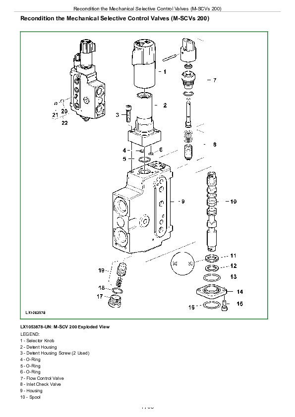
Recondition the Mechanical Selective Control Valves (M-SCVs 200)…1705
Recondition the Selective Control Valves (M-SCVs 450)…1708
Install Selective Control Valves (SCVs)…1711
Remove and Install Quick Couplers…1717
Section 70C: Hydraulic System—Axial Piston Pump (Cab Tractors)…1611
Group 05: Rockshaft Controls…1611
Special Tools…1845
Specifications…1856
Selective Control Valves — Removing and Installing Actuating Elements…1616
Selective Control Valves — Adjusting Bowden Cable…1620
Group 10: Charge Pump and Hydraulic Pump…1611
Special Tools…1845
Specifications…1856
Charge Pump—Exploded View…1624
Remove and Install Charge Pump…1625
Hydraulic Pump—Exploded View…1627
Remove, Inspect, and Install Lube Oil Valve…1629
Hydraulic Oil Reservoir — Restrictor…1630
Pressure and Flow Regulator—Exploded View…1631
Remove, Inspect, and Install Pressure and Flow Regulator…1633
Repair Pressure and Flow Regulator…1635
Remove Hydraulic Pump…1637
Install Hydraulic Pump…1639
Group 15: Valve Block…1611
Special Tools…1845
Specifications…1856
Hydraulic System Repair Instructions…1644
Remove Hitch Valve…1646
Disassemble, Repair, and Assemble Hitch Valve…1648
Install Hitch Valve…1651
Remove and Install Stepper Motor…1653
Remove Priority Valve 1…1654
Disassemble, Repair, and Assemble Priority Valve 1…1655
Install Priority Valve 1…1657
Remove Priority Valves 2 and 3…1658
Disassemble, Repair, and Assemble Priority Valves 2 and 3…1661
Install Priority Valves 2 and 3…1665
Group 20: Rockshaft…1612
Special Tools…1845
Other Materials…1669
Specifications…1856
Position Sensor and Toothed Segment—Exploded View…1671
Remove and Install Position Sensor and Toothed Segment…1672
Rockshaft—Exploded View…1675
Remove and Install Rockshaft…1679
Remove and Install Rockshaft Support…1682
Remove and Install Lift Cylinders…1684
Draft Sensor and Draft Link Support—Exploded View…1686
Remove and Install Draft Link Support…1690
Group 25: Selective Control Valves and Quick Couplers…1612
Special Tools…1845
Specifications…1856
Repair Instructions for the Selective Control Valves (SCVs) and Couplers…1701
Remove Selective Control Valves (SCVs)…1703
Recondition the Mechanical Selective Control Valves (M-SCVs 200)…1705
Recondition the Selective Control Valves (M-SCVs 450)…1708
Install Selective Control Valves (SCVs)…1711
Remove and Install Quick Couplers…1717
Section 80: Miscellaneous…1719
Group 05: Remove and Install Components…1719
Special Tools…1845
Specifications…1856
Remove and Install Hood…1723
Remove and Install Main Frame—6100J, 6115J, 6125J, and 6135J Tractors…1725
Remove and Install Main Frame—6150J, 6170J, 6190J, and 6210J Tractors…1731
Remove and Install Front Axle—Standard Front Axle…1738
Remove and Install Front Axle—John Deere 3 Meters Front Axle…1742
Group 10: Main Frame…1719
Special Tools…1845
Specifications…1856
Repair Main Frame…1748
Group 15: Front Wheels, Rear Wheels and Fenders…1719
Special Tools…1845
Specifications…1856
Remove and Install Front Fenders…1756
Remove and Install Front and Rear Wheels…1763
Repair Front and Rear Wheels…1767
Service Heavy-Duty Wheel Clamps…1773
Group 20: Center Link Bracket and Swinging Drawbar…1719
Specifications…1856
Check Swinging Drawbar Wear…1781
Remove and Install Center Link Bracket…1782
Repair Swinging Drawbar—6100J, 6115J, 6125J, and 6135 Tractors…1784
Repair Swinging Drawbar—6150J, 6170J, 6190J, 6210J Tractors…1788
Repair Swinging Drawbar—6150J, 6170J, 6190J, 6210J Tractors…1788
Repair Drawbar with Ball Pin—6170J, 6190J, and 6210J Tractors…1790
Adjust Hammer Strap…1792
Section 90A: Open Operator's Station…1793
Group 05: Remove and Install Components…1793
Specifications…1856
Remove and Install Open Operator's Station…1796
Remove and Install Open Operator’s Station Console Cover…1804
Group 10: Open Operator's Station…1793
Specifications…1856
Remove and Install Open Operator’s Station Roof…1808
Section 90B: Cab…1810
Group 05: Remove and Install Components…1810
Special Tools…1845
Specifications…1856
Cab Mounts—Exploded View…1815
Swing Up Cab…1818
Swing Down Cab…1826
Remove and Install Cab…1830
Remove and Install Front Console Cover…1841
Group 10: Air-Conditioning System…1810
Special Tools…1845
Tightening Torque for Refrigerant Hoses…1846
Safety Regulations…1847
Handling Refrigerant…1848
Air Conditioning System – Safety at Work…1849
Storage of Refrigerant Containers…1851
Refrigerant R134a…1852
Air Conditioning System – Preventive Maintenance…1853
Important…1854
Other Material…1855
Specifications…1856
General information…1857
Air conditioning system – Instructions for starting up the DENSO air conditioning compressor…1858
Filling the Cylinder…1859
Charging Air Conditioning System (With Loading Cylinder)…1861
Charging Air Conditioning System (With Recovery/Recycling and Charging Station)…1863
Adding Oil to the Air Conditioning System…1864
Leak Test…1865
Evacuate Air Conditioning System…1866
Cleaning the Air Conditioning System…1868
Remove and Install Compressor…1869
Check Refrigerant Oil Level…1873
Disassemble and Assemble Magnetic Clutch of Air Conditioner Compressor…1874
Check Clutch Hub Clearance…1876
Remove and Install Condenser…1877
Replace Air Conditioner Receiver-Drier…1879
Replace Expansion Valve…1880
Remove and Install Evaporator and Expansion Valve…1881
Installing Condensation Water Drain Hoses…1883
Layout of Condensation Water Drain Hoses…1884
Vacuum Pump — General Information…1885
Group 15: Heating System…1811
Fan and Heater, Disassembling…1888
Replace Cab Air Filter…1890
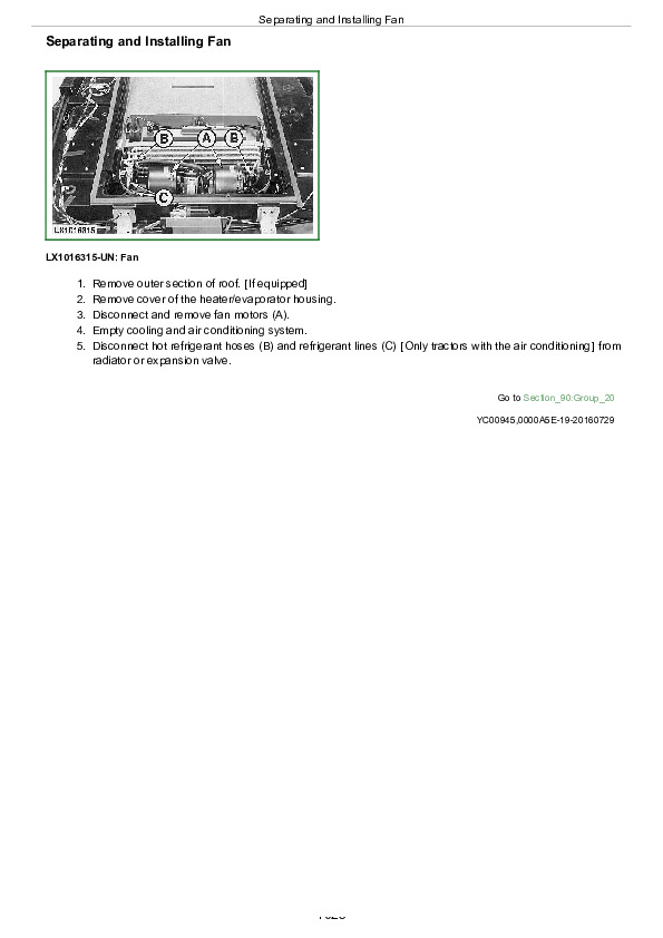
Separating and Installing Fan…1892
Separating and Installing Heater Regulator…1893
Separating Heater/Evaporator Housing…1894
Group 20: Operator's Cab…1811
Removing Cab Frame…1897
Remove and Install Outer Roof…1898
Removing and Installing Windshield…1899
Remove and Install Rear Window…1900
Installing Door Lock…1902
Adjusting Window Contact Pressure…1904
Remove and Install Operator's Cab Door…1905
Removing and Installing Sun-Visor Roller…1907
Remove and Install Operator’s Seat…1908
Remove and Install Instructional Seat…1910
Section 99: Tools…1911
Group 05: Special Tools (Dealer-Fabricated)…1911
DFLX1 – Adapter Strut…1913
DFLX7 – Turning Device…1914
DFLX13 – Holding Device…1915
DFLX15 – Holding Device for Tractor Components…1916
DFLX29 – Support…1917
DFLX42 – Turning Device…1918
Lifting Device…1919
Suspension Device…1920
Suspension Eyes for Operator's Cab…1921
Holding Tool…1922
Wooden Block…1923
DFRW79 – Piston Retainer Tool…1924
Retainer Installer…1925
Retainer…1926
Socket Wrench Insert…1927
Seal Installer…1928
Assembling and Guide Drivers…1929
Special Wrench…1930
Bushing…1931
Quick Coupler Securing Support…1932
Lifting Tool…1933
John Deere Tractors 6100J, 6115J, 6125J, 6135J, 6150J, 6170J, 6190J, 6210J Repair Service Manual (TM808719)