Posted on

John Deere 240LC-8B Excavator Repair Service Manual (TM11479)


INSTANT DOWNLOAD


Complete Repair service manual for John Deere 240LC-8B Excavator, with all the technical information to maintain, repair, and rebuild like professional mechanics.

John Deere XCG240LC-8B Excavators workshop service repair manual includes:
* Numbered table of contents easy to use so that you can find the information you need fast.
* Detailed sub-steps expand on repair procedure information
* Numbered instructions guide you through every repair procedure step by step.
* Notes, cautions and warnings throughout each chapter pinpoint critical information.
* Bold figure number help you quickly match illustrations with instructions.
* Detailed illustrations, drawings and photos guide you through every procedure.
* Enlarged inset helps you identify and examine parts in detail.

TM11479 English – John Deere XCG240LC-8B Excavator Technical Manual (Repair).pdf
tm11608 Chinese – 240LC-8B Excavator Repair.pdf

ide2370en English – Isuzu INDUSTRIAL DIESEL ENGINE AA-4BG1T, AA-6BG1, BB-4BG1T, BB-6BG1T Workshop Manual.pdf
ide2370sc Chinese – INDUSTRIAL DIESEL ENGINE AA-4BG1T, AA-6BG1, BB-4BG1T, BB-6BG1T Workshop Manual

PRODUCT DETAILS:
Total Pages: 533 pages
File Format: PDF (Windows & Mac & Linux)
Language: English

MAIN SECTIONS
Foreword
General Information
Safety
Torque Values
Tracks
Track System
Axles and Suspension Systems
Axle Shaft, Bearings, and Reduction Gears
Hydraulic System
Engine
Removal and Installation
Engine Auxiliary System
Cooling Systems
Speed Controls
Intake System
External Exhaust Systems
External Fuel Supply Systems
Dampener Drive
Elements
Frame or Supporting Structure
Frame Installation
Chassis Weights
Operator`s Station
Removal and Installation
Operator Enclosure
Seat and Seat Belt
Heating and Air Conditioning
Excavator
Buckets
Frames
Hydraulic System
Swing or Pivoting System
Mechanical Drive Elements
Hydraulic System
Dealer Fabricated Tools

TABLE OF CONTENTS
Section 00: General Information…8
Group 0001: Safety…8
Recognize Safety Information…11
Follow Safety Instructions…12
Operate Only If Qualified…13
Wear Protective Equipment…14
Avoid Unauthorized Machine Modifications…15
Add Cab Guarding for Special Uses…16
Inspect Machine…17
Stay Clear of Moving Parts…18
Avoid High-Pressure Fluids…19
Avoid High-Pressure Oils…20
Work In Ventilated Area…21
Prevent Fires…22
Prevent Battery Explosions…23
Handle Chemical Products Safely…24
Dispose of Waste Properly…25
Prepare for Emergencies…26
Use Steps and Handholds Correctly…27
Start Only From Operator's Seat…28
Use and Maintain Seat Belt…29
Prevent Unintended Machine Movement…30
Avoid Work Site Hazards…31
Keep Riders Off Machine…33
Avoid Backover Accidents…34
Avoid Machine Tip Over…35
Do Not Lift Objects…37
Add and Operate Attachments Safely…38
Park and Prepare for Service Safely…39
Service Cooling System Safely…40
Remove Paint Before Welding or Heating…41
Make Welding Repairs Safely…42
Drive Metal Pins Safely…43
Safety Signs…44
Group 0003: Torque Values…9
Unified Inch Bolt and Cap Screw Torque Values…62
Metric Bolt and Cap Screw Torque Values…64
Additional Metric Cap Screw Torque Values…66
Check Oil Lines And Fittings…68
Service Recommendations for O-Ring Boss Fittings…69
Service Recommendations For Flat Face O-Ring Seal Fittings…71
Service Recommendations for 37° Flare and 30° Cone Seat Connectors…73
Service Recommendations For Flared Connections—Straight or Tapered Threads…75
Service Recommendations For Inch Series Four Bolt Flange Fittings…77
Service Recommendations for Metric Series Four Bolt Flange Fitting…79
Section 01: Tracks…81
Group 0130: Track System…81
Track Roller Remove and Install…86
Track Roller Pressure Test…90
Track Carrier Roller Remove and Install…93
Track Shoe Remove and Install…97
Track Chain Remove and Install…99
Sprocket Remove and Install…105
Front Idler Remove and Install…107
Track Adjuster and Recoil Spring Remove and Install…110
Track Adjuster and Recoil Spring Disassemble and Assemble…111
Section 02: Axles and Suspension Systems…117
Group 0250: Axle Shaft, Bearings, and Reduction Gears…117
Travel Gearbox and Motor Remove and Install…122
Travel Gearbox Disassemble…126
Travel Gearbox Assemble…134
Group 0260: Hydraulic System…117
Travel Motor and Park Brake Remove and Install…142
Travel Motor and Park Brake Disassemble and Assemble…143
Travel Motor Cover Disassemble and Assemble…158
Travel Speed Change Solenoid Valve Remove and Install…162
Travel Motor and Park Brake Start-Up Procedure…166
Section 04: Engine…167
Group 0400: Removal and Installation…167
Engine Remove and Install…185
Fuel Shutoff Actuator Remove and Install…202
Section 05: Engine Auxiliary System…205
Group 0510: Cooling Systems…205
Radiator Remove and Install…209
Hydraulic Oil Cooler Remove and Install…212
Intercooler Remove and Install…221
Cooling Package Remove and Install…223
Fan, Fan Guard, and Fan Shroud Remove and Install…238
Group 0515: Speed Controls…205
Speed Control Linkage Remove and Install…243
Engine Speed Control Actuator Remove and Install…245
Group 0520: Intake System…205
Air Cleaner Remove and Install…252
Group 0530: External Exhaust Systems…205
Muffler Remove and Install…259
Group 0560: External Fuel Supply Systems…205
Fuel Tank Remove and Install…270
Primary Fuel Filter (Water Separator) Base Remove and Install (S.N. —1000012)…279
Water Separator Filter Base Remove and Install (S.N. 1000013— )…281
Final Fuel Filter Base Remove and Install (S.N. —1000012)…284
Section 07: Dampener Drive…286
Group 0752: Elements…286
Dampener Drive (Flex Coupling) Remove and Install…292
Section 17: Frame or Supporting Structure…297
Group 1740: Frame Installation…297
Welding On Machine…299
Welding Repair of Major Structure…300
Group 1749: Chassis Weights…297
Counterweight Remove and Install…305
Section 18: Operator's Station…308
Group 1800: Removal and Installation…308
Cab Remove and Install…319
Group 1810: Operator Enclosure…308
Sliding Windows Remove and Install…330
Windowpanes Remove and Install…331
Windowpanes Dimensions…332
Group 1821: Seat and Seat Belt…308
Mechanical Suspension Seat Remove and Install…338
Seat Belt Remove and Install…340
Left and Right Console Covers Remove and Install…342
Group 1830: Heating and Air Conditioning…308
Refrigerant Cautions and Proper Handling…346
R134a Refrigerant Oil Information…347
R134a Refrigerant Recovery, Recycling, and Charging Stations Installation Procedure…349
R134a Refrigerant Recover…351
R134a System Evacuate…352
R134a System Charge…354
Compressor Remove and Install…355
Condenser Remove and Install…358
Heater and Air Conditioner Remove and Install…359
Receiver-Dryer Remove and Install…366
Section 33: Excavator…368
Group 3302: Buckets…368
Bucket Remove and Install…370
Group 3340: Frames…368
Bucket Links Remove and Install…373
Arm Remove and Install…375
Boom Remove and Install…378
Group 3360: Hydraulic System…368
Apply Vacuum to Hydraulic Oil Tank…385
Hydraulic Oil Cleanup Procedure…387
Hydraulic Component Failure Cleanup Procedure…390
Pump 1 and 2 Remove and Install…393
Pump 1 and 2 Disassemble and Assemble…398
Pump 1 and 2 Start-Up Procedure…402
Pump 1 and 2 Regulator Remove and Install…404
Pilot Pump Remove and Install…408
Accumulator Manifold Remove and Install…411
Accumulator Manifold Safety Discharge Procedure…415
Solenoid Valve Remove and Install—Pressure Boost…416
Pilot Control Valve (Left and Right) Remove and Install…418
Travel Pilot Control Valve Remove and Install…428
Pilot Distribution Manifold Remove and Install…424
Control Valve Remove and Install…428
Control Valve (Left and Right) Disassemble and Assemble…434
Hydraulic Oil Tank Remove and Install…439
Hydraulic Oil Tank Disassemble and Assemble…451
Restriction Valve Remove and install…453
Hydraulic Oil Cooler Bypass Valve Remove and Install…455
Boom Cylinder Remove and Install…457
Arm Cylinder Remove and Install…464
Bucket Cylinder Remove and Install…468
Hydraulic Cylinder Bleed Procedure…472
Section 43: Swing or Pivoting System…473
Group 4350: Mechanical Drive Elements…473
Swing Gear Case Remove and Install…478
Swing Gear Case Disassemble and Assemble…482
Upperstructure Remove and Install…488
Swing Bearing Remove and Install…492
Group 4360: Hydraulic System…473
Rotary Manifold Remove and Install…499
Rotary Manifold Air Test…503
Swing Motor and Park Brake Remove and Install…505
Swing Motor and Park Brake Disassemble…508
Swing Motor and Park Brake Assemble…510
Swing Motor and Park Brake Start-Up Procedure…513
Crossover Relief Valve and Make-Up Check Valve Remove and Install…514
Swing Park Brake Release Valve Remove and Install…517
Section 99: Dealer Fabricated Tools…519
Group 9900: Dealer Fabricated Tools…519
DFT1087 Track Roller Spring Disassembly and Assembly Tool Guard…521
DFT1110 Spacer…522
DFT1322 Idler Removal Bracket…523
ST4920 Track Recoil Spring Disassembly and Assembly Tool…525

John Deere 240LC-8B Excavator Repair Service Manual (TM11479)


INSTANT DOWNLOAD


Posted on

John Deere 240LC-8B Excavator Operation and Test Technical Manual (TM11478)


INSTANT DOWNLOAD


Complete diagnostic technical manual with Electrical Wiring Diagrams for John Deere 240LC-8B Excavators, with all the shop information to maintain, diagnose, and rebuild like professional mechanics.

John Deere XCG240LC-8B Excavator workshop service & repair manual includes:
* Numbered table of contents easy to use so that you can find the information you need fast.
* Detailed sub-steps expand on repair procedure information
* Numbered instructions guide you through every repair procedure step by step.
* Troubleshooting and electrical service procedures are combined with detailed wiring diagrams for ease of use.
* Notes, cautions and warnings throughout each chapter pinpoint critical information.
* Bold figure number help you quickly match illustrations with instructions.
* Detailed illustrations, drawings and photos guide you through every procedure.
* Enlarged inset helps you identify and examine parts in detail.

TM11478 English – John Deere XCG240LC-8B Excavator Technical Manual (Operation and Test).pdf
tm11607 Chinese – XCG240LC-8B Excavator Operation and Test

PRODUCT DETAILS:
Total Pages: 621 pages
File Format: PDF (Windows & Mac & Linux)
Language: English

MAIN SECTIONS
Foreword
General Information
Safety
Diagnostics
Advanced Display Unit (ADU) Diagnostic Trouble Codes
Flex Load Controller (FLC) Diagnostic Trouble Codes
Sealed Switch Module (SSM) Diagnostic Trouble Codes
Operational Checkout Procedure
Engine
Theory of Operation
Diagnostic Information
Adjustments
Tests
Electrical System
System Information
System Diagrams
Sub-System Diagnostics
Monitor Operation
References
Power Train
Theory of Operation
Diagnostic Information
Hydraulic System
Theory of Operation
Diagnostic Information
Tests
Heating and Air Conditioning
Theory of Operation
Diagnostic Information
Tests

TABLE OF CONTENTS…1
Section 9000: General Information…15
Group 01: Safety…15
Recognize Safety Information…18
Follow Safety Instructions…19
Operate Only If Qualified…20
Wear Protective Equipment…21
Avoid Unauthorized Machine Modifications…22
Add Cab Guarding for Special Uses…23
Inspect Machine…24
Stay Clear of Moving Parts…25
Avoid High-Pressure Fluids…26
Avoid High-Pressure Oils…27
Work In Ventilated Area…28
Prevent Fires…29
Prevent Battery Explosions…30
Handle Chemical Products Safely…31
Dispose of Waste Properly…32
Prepare for Emergencies…33
Use Steps and Handholds Correctly…34
Start Only From Operator's Seat…35
Use and Maintain Seat Belt…36
Prevent Unintended Machine Movement…37
Avoid Work Site Hazards…38
Keep Riders Off Machine…40
Avoid Backover Accidents…41
Avoid Machine Tip Over…42
Do Not Lift Objects…44
Add and Operate Attachments Safely…45
Park and Prepare for Service Safely…46
Service Cooling System Safely…47
Remove Paint Before Welding or Heating…48
Make Welding Repairs Safely…49
Drive Metal Pins Safely…50
Section 9001: Diagnostics…51
Group 10: Advanced Display Unit (ADU) Diagnostic Trouble Codes…51
000158.03 – Key Switch Voltage Voltage High…51
000158.04 – Key Switch Voltage Voltage Low…51
000168.03 – System Voltage Voltage High…51
000168.04 – System Voltage Voltage Low…51
000442.00 – Display Temperature Very High…51
000442.01 – Display Temperature Very Low…51
001491.11 – LCD Backlight Failure Cause Unknown…51
003597.02 – 5.0 V Power Supply Intermittent…51
003598.02 – 1.5 V Power Supply Intermittent…51
003599.02 – 3.3 V Power Supply Intermittent…51
523436.14 – ADU Watchdog See Manual…51
523438.31 – Memory Error No Information…51
523651.02 – Memory Stack Overflow Intermittent…51
523773.03 – CAN High Voltage High…51
523773.04 – CAN High Voltage Low…51
523774.03 – CAN Low Voltage High…51
523774.04 – CAN Low Voltage Low…51
524076.10 – Info Button Stuck Bad Rate of Change…51
524077.10 – Back Button Stuck Bad Rate of Change…51
524078.10 – Menu Button Stuck Bad Rate of Change…51
524080.10 – Down Arrow Button Stuck Bad Rate of Change…51
524082.10 – Up Arrow Button Stuck Bad Rate of Change…51
Group 20: Flex Load Controller (FLC) Diagnostic Trouble Codes…51
000096.03 – Fuel Level Sensor Voltage High…51
000096.04 – Fuel Level Sensor Voltage Low…51
000100.01 – Engine Oil Pressure Very Low…51
000100.03 – Engine Oil Pressure Voltage High…51
000107.00 – Engine Air Filter Restriction Very High…51
000107.03 – Engine Air Filter Restriction Voltage High…51
000110.00 – Engine Coolant Temperature Very High…51
000110.04 – Engine Coolant Temperature Voltage Low…52
000167.03 – Alternator Output Voltage High…52
000167.04 – Alternator Output Voltage Low…52
000190.08 – Engine Speed Sensor Abnormal Frequency Input Data…52
000632.06 – Engine Fuel Shutoff Current Above Normal…52
000638.04 – Throttle Actuator Low Voltage…52
000638.07 – Throttle Actuator Mechanical Failure or Calibration…52
000638.09 – Throttle Actuator Abnormal Update Rate…52
000638.12 – Throttle Actuator Bad Device or Component…52
000638.13 – Throttle Actuator Out of Calibration…52
000676.05 – Glow Plug Relay Current Low…52
000676.06 – Glow Plug Relay Current High…52
000677.05 – Engine Starter Relay Current Below Normal…52
000677.06 – Engine Starter Relay Current Above Normal…52
000742.05 – High Low Travel Speed Solenoid Current Below Normal…52
000742.06 – High Low Travel Speed Solenoid Current Above Normal…52
000882.05 – License Plate Light Current Below Normal…52
000882.06 – License Plate Light Current Above Normal…52
001041.04 – Start Signal Indicator Voltage Low…52
001638.00 – Hydraulic Oil Temperature Very High…52
001638.04 – Hydraulic Oil Temperature Voltage Low…52
001713.01 – Hydraulic Oil Filter Restriction Very Low…52
001713.03 – Hydraulic Oil Filter Switch Voltage High…52
002040.09 – ADU CAN Communication Bad Update Rate…52
002141.09 – SSM CAN Communication Bad Update Rate…52
002177.09 – Throttle Actuator CAN Communication Bad Update Rate…52
002354.05 – Right Frame Worklight Current Below Normal…52
002354.06 – Right Frame Worklight Current Above Normal…52
002386.05 – Rotary Beacon Light Current Below Normal…52
002386.06 – Rotary Beacon Light Current Above Normal…52
002400.05 – Boom Worklight Current Below Normal…52
002400.06 – Boom Worklight Current Above Normal…52
003509.03 – Sensor Supply 1 Voltage High…52
003509.04 – Sensor Supply 1 Voltage Low…53
003510.03 – Sensor Supply 2 Voltage High…53
003510.04 – Sensor Supply 2 Voltage Low…53
003511.03 – Sensor Supply 3 Voltage High…53
003511.04 – Sensor Supply 3 Voltage Low…53
003512.03 – Sensor Supply 4 Voltage High…53
003512.04 – Sensor Supply 4 Voltage Low…53
520544.01 – GPS Anti-Vandalism Switch Voltage Very Low…53
520544.03 – GPS Anti-Vandalism Switch Voltage High…53
520545.05 – Pressure Boost Solenoid Current Low…53
520545.06 – Pressure Boost Solenoid Current High…53
520546.04 – Pilot Enable Switch Voltage Low…53
520547.04 – Pressure Boost Switch Voltage Low…53
520548.04 – Travel Pressure Switch Voltage Low…53
520549.04 – Boom Pressure Switch Voltage Low…53
520551.06 – Travel Alarm Current High…53
522141.05 – Main Pump Solenoid Current Below Normal…53
522141.06 – Main Pump Solenoid Current Above Normal…53
522427.04 – Front Wiper Park Voltage Low…53
522429.05 – Pilot Enable Solenoid Current Below Normal…53
522429.06 – Pilot Enable Solenoid Current Above Normal…53
522434.05 – Front Wiper Low Speed Current Low…53
522434.06 – Front Wiper Low Speed Current High…53
522435.05 – Front Wiper High Speed Current Low…53
522435.06 – Front Wiper High Speed Current High…53
522797.05 – Front Washer Pump Current Low…53
522797.06 – Front Washer Pump Current High…53
522944.05 – Left Front Cab Worklight Current Below Normal…53
522944.06 – Left Front Cab Worklight Current Above Normal…53
522945.05 – Right Front Cab Worklight Current Below Normal…53
522945.06 – Right Front Cab Worklight Current Above Normal…53
523440.04 – Unswitched Power Voltage Low…53
524089.03 – P1 Pump Pressure Sensor Voltage High…53
524089.04 – P1 Pump Pressure Sensor Voltage Low…54
524090.03 – P2 Pump Pressure Sensor Voltage High…54
524090.04 – P2 Pump Pressure Sensor Voltage Low…54
524096.02 – Throttle Dial Bad Input Data…54
Group 30: Sealed Switch Module (SSM) Diagnostic Trouble Codes…54
000629.12 – Controller Fault…54
002033.09 – FLC CAN Communication Bad Update Rate…54
520752.04 – Auto Idle Button Stuck…54
520752.09 – Auto Idle Button Bad Update Rate…54
520753.04 – Hydraulic Power Button Stuck…54
520753.09 – Hydraulic Power Button Bad Update Rate…54
520754.04 – Unused Button 19 Stuck…54
520754.09 – Unused Button 19 Bad Update Rate…54
520755.04 – Unused Button 20 Stuck…54
520755.09 – Unused Button 20 Bad Update Rate…54
523335.04 – Travel Alarm Cancel Button Stuck…54
523335.09 – Travel Alarm Cancel Button Bad Update Rate…54
523336.04 – Travel Setting Button Stuck…54
523336.09 – Travel Setting Button Bad Update Rate…54
523338.04 – Unused Button 23 Stuck…54
523338.09 – Unused Button 23 Bad Update Rate…54
523339.04 – Unused Button 22 Stuck…54
523339.09 – Unused Button 22 Bad Update Rate…54
523340.04 – Unused Button 21 Stuck…54
523340.09 – Unused Button 21 Bad Update Rate…54
523849.04 – Unused Button 16 Stuck…54
523849.09 – Unused Button 16 Bad Update Rate…54
523850.04 – Unused Button 15 Stuck…54
523850.09 – Unused Button 15 Bad Update Rate…54
523852.04 – Unused Button 14 Stuck…54
523852.09 – Unused Button 14 Bad Update Rate…54
523854.04 – Front Washer Button Stuck…54
523854.09 – Front Washer Button Bad Update Rate…54
523855.04 – Front Wiper Button Stuck…55
523855.09 – Front Wiper Button Bad Update Rate…55
523856.04 – Unused Button 11 Stuck…55
523856.09 – Unused Button 11 Bad Update Rate…55
523857.04 – Unused Button 10 Stuck…55
523857.09 – Unused Button 10 Bad Update Rate…55
523858.04 – Boom Worklight Button Stuck…55
523858.09 – Boom Worklight Button Bad Update Rate…55
523860.04 – Cab Front Worklight Button Stuck…55
523860.09 – Cab Front Worklight Button Bad Update Rate…55
523861.04 – Front Frame Worklight Button Stuck…55
523861.09 – Front Frame Worklight Button Bad Update Rate…55
523862.04 – Unused Button 6 Stuck…55
523862.09 – Unused Button 6 Bad Update Rate…55
523863.04 – Unused Button 5 Stuck…55
523863.09 – Unused Button 5 Bad Update Rate…55
523864.04 – Unused Button 4 Stuck…55
523864.09 – Unused Button 4 Bad Update Rate…55
523865.04 – Rotary Beacon Button Stuck…55
523865.09 – Rotary Beacon Button Bad Update Rate…55
523867.04 – Unused Button 2 Stuck…55
523867.09 – Unused Button 2 Bad Update Rate…55
523868.04 – Unused Button 1 Stuck…55
523868.09 – Unused Button 1 Bad Update Rate…55
Section 9005: Operational Checkout Procedure…377
Group 10: Operational Checkout Procedure…377
Operational Checkout Procedure…377
Section 9010: Engine…404
Group 05: Theory of Operation…404
Engine Component Location…409
Engine Fuel System Operation (S.N. —1000012)…413
Engine Fuel System Operation (S.N. 1000013—)…414
Engine Start Aid Operation…415
Engine Speed Control System Operation…416
Group 15: Diagnostic Information…404
Isuzu CC-6BG1TRP Engine…418
Engine Cranks But Will Not Start…404
Engine Does Not Stop With Key Switch…404
Group 20: Adjustments…404
Engine Speed Control Linkage Check and Adjustment…422
Fuel Shut-Off Actuator Adjustment…423
Group 25: Tests…404
Engine Speed Test…427
Clamp-On Tachometer Installation…428
Section 9015: Electrical System…429
Group 05: System Information…429
Electrical Diagram Information…435
Electrical Schematic Symbols…439
Group 10: System Diagrams…429
Fuse and Relay Specifications…444
System Functional Schematic, Component Location, and Wiring Diagram Master Legend…447
System Functional Schematic…451
Left Frame Harness (W10) Component Location…455
Left Frame Harness (W10) Wiring Diagram…457
Middle Frame Harness (W11) Component Location…459
Middle Frame Harness (W11) Wiring Diagram…464
Right Frame Harness (W12) Component Location…466
Right Frame Harness (W12) Wiring Diagram…468
Load Center Harness (W13) Component Location…469
Load Center Harness (W13) Wiring Diagram…471
Cab Harness (W14) Component Location…473
Cab Harness (W14) Wiring Diagram…475
Right Console Harness (W15) Component Location…476
Right Console Harness (W15) Wiring Diagram…477
Cab Roof Harness (W16) Component Location…478
Cab Roof Harness (W16) Wiring Diagram…480
Boom Light Harness (W17) Component Location…481
Boom Light Harness (W17) Wiring Diagram…482
Diesel Fired Coolant Heater Harness (W18) Component Location…484
Diesel Fired Coolant Heater Harness (W18) Wiring Diagram…486
Group 15: Sub-System Diagnostics…429
Controller Area Network (CAN) Theory of Operation…489
Starting and Charging Circuit Theory of Operation…491
Flex Load Controller (FLC) Circuit Theory of Operation…494
Advanced Display Unit (ADU) Circuit Theory of Operation…499
Fuel Shutoff Actuator Theory of Operation…501
Group 16: Monitor Operation…430
Advanced Display Unit (ADU)—Service Mode…506
Advanced Display Unit (ADU)—Clear Codes…508
Advanced Display Unit (ADU)—Enable Options…509
Advanced Display Unit (ADU)—Throttle Actuator Cal…510
Advanced Display Unit (ADU)—Telematic…511
Advanced Display Unit (ADU) Screen is Blank Diagnostic Procedure…430
Group 20: References…430
Fuse and Relay Test…519
Controller Area Network (CAN) Circuit Test…523
Electrical Component Checks…531
Electrical Component Specifications…536
Solenoid Test…430
Alternator Test…547
Engine Speed Control Actuator Calibration…549
Fuel Shut-Off Actuator Check…550
Replace DEUTSCH DEUTSCH is a trademark of the Deutsch Co. Connectors…430
Replace DEUTSCH DEUTSCH is a trademark of Deutsch Co. Rectangular or Triangular Connectors…430
Install DEUTSCH DEUTSCH is a trademark of the Deutsch Co. Contact…430
Replace WEATHER PACK WEATHER PACK is a trademark of Packard Electric. Connector…430
Install WEATHER PACK WEATHER PACK is a trademark of Packard Electric. Contact…430
Replace (Pull Type) Metri-Pack™ Connectors…564
Replace (Push Type) Metri-Pack™ Connectors…566
Replace CINCH CINCH is a trademark of the Cinch Co. Connectors…430
Install CINCH CINCH is a trademark of the Cinch Co. Contact…430
Repair 32 and 48 Way CINCH CINCH is a trademark of the Cinch Co. Connectors…430
Remove Connector Body from Blade Terminals…575
Section 9020: Power Train…576
Group 05: Theory of Operation…576
Track Adjuster and Recoil Spring Operation…578
Travel Gearbox Operation…579
Group 15: Diagnostic Information…576
Noisy or Loose Track Chain…576
Tight Track Chain…576
Frequent Track Tension Adjustment Required…576
Excessive Oil Leakage From Front Idler, Track Rollers, or Carrier Rollers…576
Bent Track Shoes…576
Section 9025: Hydraulic System…594
Group 05: Theory of Operation…594
Hydraulic System Operation…598
Pilot System Operation…599
Pilot Pump Operation…600
Pilot Shutoff Solenoid Valve Operation…601
Pilot Control Valve Operation…622
Travel Pilot Control Valve Operation…622
Pilot Operation of Control Valve Operation…622
Pilot Accumulator Manifold Operation…607
Pilot Supply Manifold Operation…609
Pilot Distribution Manifold Operation…610
Pump 1 and Pump 2 Operation…612
Pump 1 and Pump 2 Regulator Operation…614
Control Valve Operation…622
Control Valve Check Valves Identification and Operation…635
Main Relief Valve Circuit Operation…638
Circuit Relief and Anticavitation Valve Operation…640
Flow Control Valve Operation…642
Flow Combiner Valve Operation…644
Arm Regenerative Valve Circuit Operation…646
Boom and Arm Reduced Leakage Valves Operation…648
Swing Reduction Gear Case Operation…650
Swing Motor, Crossover Relief Valve, and Make-Up Check Valve Operation…652
Swing Motor Park Brake Release Circuit Operation…654
Rotary Manifold Operation…655
Travel Motor and Park Brake Valve Operation…657
Travel Motor Speed Circuit Operation…658
Cylinder Operation…659
Return Filter Operation…660
Group 15: Diagnostic Information…594
All Hydraulic Functions Slow…594
Hydraulic Oil Overheats…595
No Hydraulic Functions…595
Poor Combined Operation…595
Function Does Not Stop When Control Lever Released…595
Some Functions Cannot Be Operated, All Others Are Normal…595
Some Functions Slow…595
Function Moves in Opposite Direction…595
Load Drifts Down When Control Valve Is In Neutral Position…595
Load Falls When Control Valve Is Actuated To Raise Load With Engine Running at Slow Idle…595
H (high power) Function Does Not Operate, S (Standard power) and L (low power) Mode Is Normal…595
Swing Speed Slow In Both Directions…595
Swing Speed Slow or Does Not Operate In One Direction…595
Upperstructure Drift With Swing Valve In Neutral…595
Swing Function Does Not Operate…595
Travel Park Brakes Do Not Apply…595
Track Will Not Move In One Direction…595
Track Will Not Move In Either Direction…595
Machine Mistracks at All Speeds In Both Directions…595
Slow Travel Speed or Low Power…595
Travel Is "Jerky"…595
Machine Will Not Hold Back and Park Brakes Engage and Disengage When Traveling Down an Incline…595
Machine Will Not Turn Smoothly In One Direction or Park Brake Grabs…595
Pump 1, Pump 2, and Pilot Pump Line Identification…722
Control Valve Line Identification…724
Swing Motor Line Identification…727
Pilot Control Valve-to-Pilot Distribution Manifold Component Location—Excavator Pattern…729
Pilot Control Valve-to-Pilot Distribution Manifold Component Location—Backhoe Pattern…731
Pilot Distribution Manifold-to-Control Valve Line Connections…733
Travel Hydraulic System Line Connections…747
Hydraulic System Schematic…736
Hydraulic System Component Location…745
Hydraulic System Line Connections…747
Group 25: Tests…596
JT05800 Digital Thermometer Installation…749
JT02156A Digital Pressure and Temperature Analyzer Kit Installation…750
Hydraulic Oil Cleanup Procedure…751
Hydraulic Oil Tank Pressure Release Procedure…752
Hydraulic Oil Warmup Procedure…753
Pilot Pressure Regulating Valve Test and Adjustment…755
Control Valve Spool Actuating Pilot Pressure Test…757
Pressure Boost Solenoid Valve Test…760
Travel Speed Solenoid Valve Test and Adjustment…762
Pump Control Pilot Pressure Signal Test…764
System Relief Valve Test and Adjustment…766
Circuit Relief Valve Test and Adjustment…770
Swing Motor Crossover Relief Valve Test and Adjustment…776
Travel Motor Crossover Relief Valve Test and Adjustment…779
Pump Regulator Test and Adjustment—Minimum Flow…782
Pump Regulator Test and Adjustment—Maximum Flow…785
Pump Flow Test…787
Swing Motor Leakage Test…790
Travel Motor Leakage Test…792
Cylinder Drift Test—Boom, Arm, and Bucket…795
Section 9031: Heating and Air Conditioning…798
Group 05: Theory of Operation…798
Air Conditioning System Cycle of Operation…801
Group 15: Diagnostic Information…798
Air Conditioning System Does Not Operate…798
Air Conditioner Does Not Cool Interior of Cab…798
Heater System Does Not Operate…798
Heater Does Not Warm Interior of Cab…798
Interior Windows Continue to Fog…798
Heater and Air Conditioner Component Location…816
Group 25: Tests…798
Refrigerant Cautions and Proper Handling…818
Heater and Air Conditioner Operational Checks…819
Air Conditioner Compressor Clutch Test…822
Refrigerant Leak Test…823
Refrigerant Hoses and Tubing Inspection…824
Operating Pressure Diagnostic Chart…825
Section 9900: Dealer Fabricated Tools…829
Group 99: Dealer Fabricated Tools…829
DFT1218 Split Flange Hose Cap…831

John Deere 240LC-8B Excavator Operation and Test Technical Manual (TM11478)


INSTANT DOWNLOAD


Posted on

JOHN DEERE 85G EXCAVATOR OPERATORS MANUAL (OMT337610)


INSTANT DOWNLOAD


Complete OPERATORS MANUAL for JOHN DEERE 85G EXCAVATORSS, with all the technical information to maintain & operate like professional mechanics.

OMT337610 English – JOHN DEERE 85G EXCAVATOR (PIN: 1FF085GX_ _J017001— ) OPERATORS MANUAL.pdf
omt339644 Spanish – Excavadora 85G.pdf
omt339646 French – Excavatrice 85G.pdf

TABLE OF CONTENTS
Section 1-1: Safety—Safety and Operator Conveniences…26
Safety and Operator Convenience Features…27
Section 1-2: Safety—General Precautions…28
Recognize Safety Information…29
Follow Safety Instructions…30
Operate Only If Qualified…31
Wear Protective Equipment…32
Protect Against Noise…33
Avoid Unauthorized Machine Modifications…34
Control Pattern…35
Control Pattern Selector—If Equipped…36
Add Cab Guarding for Special Uses…37
Inspect Machine…38
Stay Clear of Moving Parts…39
Avoid High-Pressure Fluids…40
Avoid High-Pressure Oils…41
Work In Ventilated Area…42
Avoid Static Electricity Risk When Refueling…43
High Debris Applications…45
Prevent Fires…46
In Case of Machine Fire…47
Prevent Battery Explosions…48
Handle Chemical Products Safely…49
Handle Starting Fluid Safely…50
Decommissioning — Proper Recycling and Disposal of Fluids and Components…51
Exhaust Filter Ash Handling and Disposal…52
Prepare for Emergencies…53
Clean Debris from Machine…54
Section 1-3: Safety—Operating Precautions…55
Use Steps and Handholds Correctly…56
Start Only From Operator's Seat…57
Use and Maintain Seat Belt…58
Prevent Unintended Machine Movement…59
Avoid Work Site Hazards…60
Keep Riders Off Machine…62
Avoid Backover Accidents…63
Inspect and Maintain ROPS…64
Avoid Machine Tip Over and Machine Damage…55
Use Special Care When Lifting Objects…67
Use Care When Swinging Machine…68
Operate Boom With Care…69
Avoid Power Lines…70
Travel Safely…71
Prevent Acid Burns…72
Add and Operate Attachments Safely…74
Section 1-4: Safety—Maintenance Precautions…75
Park and Prepare for Service Safely…76
Service Machines Safely…77
Service Cooling System Safely…78
Remove Paint Before Welding or Heating…79
Make Welding Repairs Safely…80
Drive Metal Pins Safely…81
Use Proper Lifting Equipment…82
Clean Exhaust Filter Safely…83
Section 1-5: Safety—Safety Signs…87
Safety Signs…87
Hydraulic Coupler Safety Signs—If Equipped…94
Section 2-1: Operation—Operator’s Station…95
Pedals, Levers, and Panels…96
Switch Panel…98
Switch Panel Functions…99
Rear Left Panel…101
Horn…102
Pilot Shutoff Lever…103
Engine Stop Switch…104
Rear Right Panel…105
Right Console…106
Travel Alarm and Travel Alarm Cancel Switch…107
Exhaust Filter Parked Cleaning Switch…108
Right Enable Switch…110
Auxiliary Function Enable Switch—If Equipped…111
Cab Heater and Air Conditioner…112
Selecting Display Between Celsius and Fahrenheit…115
Operating the AM/FM Radio…116
Fire Extinguisher Mounting Location…118
Secondary Exit Tool…119
Cab Dome Light Switch…120
Opening Upper Front (Secondary Exit) Window…121
Removing and Storing the Lower Front Window…123
Opening Cab Door Window…125
Adjusting the Mechanical Suspension Seat…126
Adjusting Pilot Control Lever Console Height…127
Section 2-2: Operation—Monitor Operation…128
Monitor…129
Monitor Functions…131
Monitor Start-Up…133
Main Menu…134
Main Menu—Alarm List…137
Main Menu—Air Conditioner…142
Main Menu—Radio…144
Main Menu—Setting Menu…146
Main Menu—Setting Menu—Date and Time…148
Main Menu—Setting Menu—Auto-Shutdown…149
Main Menu—Setting Menu—Auto Exhaust Filter Cleaning…150
Main Menu—Setting Menu—Sub Meter Selection…152
Main Menu—Setting Menu—Rear View Camera Monitor…154
Main Menu—Setting Menu—Display Item Selection…156
Main Menu—Setting Menu—Brightness Adjustment…158
Main Menu—Setting Menu—Language…159
Main Menu—Setting Menu—Unit Selection…160
Main Menu—Setting Menu—Main Menu Sequence Change…162
Main Menu—Information Menu…163
Main Menu—Information Menu—Operation…164
Main Menu—Information Menu—Maintenance…166
Main Menu—Information Menu—Troubleshooting…168
Main Menu—Information Menu—Monitoring…169
Section 2-3: Operation—Operating the Machine…170
Before Starting Work…172
Operator's Daily Machine Check Before Starting…173
Engine Break-In Period…175
Starting the Engine…487
Cold Weather Start Aid…178
Warm-Up Operation…179
Cold Weather Warm-Up…180
Operate Within Machine Limits…181
Digging and Grading Operation…182
Travel Pedals and Levers…185
Auxiliary Function Lever (AFL)…187
Exhaust Filter…189
Exhaust Filter Parked Cleaning…192
Control Lever Pattern Operation…195
Control Lever Pattern Conversion—If Equipped…197
Control Lever Pattern Conversion…198
Boom-Swing Pedal…199
Positioning Auxiliary Line Selector Valve—If Equipped…201
Operating Backfill Blade…203
Operating Tips—Backfill Blade…204
Operating in Water and Mud…205
Selecting Correct Track…206
Required Machine Stop Warning…207
Driving Up a Steep or Slippery Slope…210
Lower Boom With Engine Stopped…211
Parking the Machine…214
Loading Machine for Transport…215
Recovery Procedure…219
Lifting With Bucket Loop…220
Lifting With John Deere Quick Coupler…222
Lifting Machine…224
Locking the Hydraulic Coupler to the Attachment—If Equipped…226
Unlocking the Hydraulic Coupler From the Attachment—If Equipped…229
Section 3-1: Maintenance—Machine…232
Required Emission-Related Information…233
Diesel Fuel…234
Diesel Fuel Specifications…235
Lubricity of Diesel Fuel…236
Handling and Storing Diesel Fuel…237
Biodiesel Fuel…238
Testing Diesel Fuel…240
Supplemental Diesel Fuel Additives…241
Fuel Filters…242
Minimizing the Effect of Cold Weather on Diesel Engines…243
Alternative and Synthetic Lubricants…245
Lubricant Storage…246
Mixing of Lubricants…247
Diesel Engine Oil — Interim Tier 4, Final Tier 4, Stage IIIB, Stage IV, and Stage V…248
Engine Oil and Filter Service Intervals — Interim Tier 4, Final Tier 4, Stage IIIB, Stage IV, and Stage V Engines…250
Diesel Engine Oil Service Interval for Operation at High Altitude…252
Oil Filters…253
Hydraulic Oil…254
Travel Gear Case Oil…256
Grease…257
Diesel Engine Coolant (engine without wet sleeve cylinder liners)…259
Water Quality for Mixing with Coolant Concentrate…261
Operating in Warm Temperature Climates…262
Testing Coolant Freeze Point…263
Disposing of Coolant…265
Section 3-2: Maintenance—Periodic Maintenance…266
Service Machine at Specified Intervals…267
Check the Hour Meter Regularly…268
Prepare Machine for Maintenance…269
Engine Access Door…270
Open Maintenance Access Doors…271
Fuel Tank…273
Hydraulic Breaker and Crusher Attachments…274
Fluid Analysis Program Test Kits and 3-Way Coolant Test Kit…275
Service Intervals…276
Required Parts…278
Section 3-3: Maintenance—As Required…280
Clean Radiator Core and Oil Cooler…281
Clean Rear Camera Lens—If Equipped…282
Check Track Sag—Rubber Track…283
Check Track Sag—Steel Track—If Equipped…285
Adjust Track Sag…287
Clean Fuel Tank Inlet Screen…289
Drain Water and Sediment from Fuel Tank Sump…290
Drain Water and Sediment from Primary Fuel Filter and Water Separator…292
Check and Adjust Air Conditioner Belt…293
Check and Clean Radiator Air Inlet Screen…295
Check Washer Fluid Level…296
Check and Clean Air Cleaner Dust Unloader Valve…297
Clean and Tighten Battery Terminals…298
Section 3-4: Maintenance—10 Hours or Daily…299
Check Engine Oil Level…300
Check Hydraulic Tank Oil Level…302
Check Engine Coolant Level…305
Check Bucket Teeth…306
Check Seat Belt…307
Lubricate Hydraulic Coupler—If Equipped…308
Section 3-5: Maintenance—Initial Service—50 Hours…309
Inspect and Re-Torque Track Hardware…321
Section 3-6: Maintenance—Every 100 Hours…311
Lubricate Bucket and Link Pins…312
Lubricate Working Pivots…313
Lubricate Front End Pin Joints…314
Section 3-7: Maintenance—Every 250 Hours…317
Check Travel Gear Case Oil Level…318
Drain Water and Sediment From Hydraulic Tank…319
Lubricate Blade Pins…320
Inspect and Re-Torque Track Hardware…321
Check Hybrid Battery Electrolyte Level—If Equipped…323
Take Engine Oil Sample…326
Section 3-8: Maintenance—Every 500 Hours…327
Drain and Refill Engine Oil and Replace Filter…328
Lubricate Swing Bearing Gear…330
Lubricate Control Lever Universal Joint…332
Replace Primary Fuel Filter and Water Separator…333
Replace Final Fuel Filter…335
Lubricate Swing Bearing…337
Check Air Intake Hose…338
Clean Cab Fresh Air and Cab Recirculating Air Filters…339
Take Fluid Samples…341
Section 3-9: Maintenance—Every 1000 Hours…342
Replace Pilot System Oil Filter…343
Check and Adjust Engine Valve Lash…346
Replace Hydraulic Tank Oil Filter…347
Check and Adjust Fan Belt Tension…350
Replace Engine Air Cleaner Element…352
Check Coolant Condition…354
Check Starter and Alternator…355
Section 3-10: Maintenance—Every 2000 Hours…356
Drain and Refill Travel Gear Case Oil…357
Clean Engine Crankcase Ventilation Tube…359
Section 3-11: Maintenance—Every 3000 Hours…360
Service Exhaust Filter…361
Section 3-12: Maintenance—Every 4000 Hours…362
Replace Swing Drain Filter (S.N. —22111)…363
Replace Hydraulic Tank Vent Cap Filter…365
Section 3-13: Maintenance—Every 5000 Hours…368
Drain and Refill Hydraulic Tank Oil…369
Drain Cooling System…373
Cooling System Fill and Deaeration Procedure…376
Section 4-1: Miscellaneous—Machine…378
Bleed Fuel System…379
Bleed Hydraulic System…491
Do Not Service or Adjust Injection Nozzles or High-Pressure Fuel Pump…382
Do Not Service Control Valves, Cylinders, Pumps, or Motors…383
Precautions for Alternator and Regulator…384
Handling, Checking, and Servicing Batteries Carefully…385
Using Battery Charger…388
Using Booster Batteries—24-Volt System…390
Replacing Batteries…391
Welding on Machine…392
Keep Electronic Control Unit Connectors Clean…393
Adding 12-Volt Accessories…394
Replacing Fuses…395
Keep ROPS Installed Properly…399
Replacing Seat Belt…400
Clean Machine Regularly…402
Connecting and Disconnecting Auxiliary Lines…403
Replacing Bucket Teeth…406
Replacing Bucket Teeth—TK Series…408
Removing the Bucket…409
Installing Bucket With Quick Coupler…410
Track Sag General Information…412
Check Track Shoe Hardware…413
Rubber Track Care…414
Removing and Installing Rubber Track…415
Converting the Track…418
Hardware Torque Specifications…419
Unified Inch Bolt and Screw Torque Values…420
Metric Bolt and Screw Torque Values…423
Section 4-2: Miscellaneous—Operational Checkout…426
Operational Checkout…426
Section 4-3: Miscellaneous—Troubleshooting…485
Troubleshooting Procedure…486
Engine…487
Hydraulic System…491
Electrical System…493
Section 4-4: Miscellaneous—Storage…496
Prepare Machine for Storage…497
Monthly Storage Procedure…499
Section 4-5: Miscellaneous—Machine Numbers…501
Record Product Identification Number (PIN)…502
Record Engine Serial Number…503
Record Hydraulic Coupler Serial Number—If Equipped…504
Keep Proof of Ownership…505
Keep Machines Secure…506
Section 4-6: Miscellaneous—Specifications…507
Engine Specifications…508
Drain and Refill Capacities…509
Machine Specifications…510
Working Ranges…512
Excavator Lift Capacity—Blade: 2370 mm (7 ft 9 in); Arm: 1.62 m (5 ft 4 in); Bucket: 0.28 m3 (0.37 yd3); Rubber Crawler Pad: 450 mm (1 ft 6 in)…507
Excavator Lift Capacity—Blade: 2370 mm (7 ft 9 in); Arm: 2.12 m (6 ft 11 in); Bucket: 0.28 m3 (0.37 yd3); Rubber Crawler Pad: 450 mm (1 ft 6 in)…507
Excavator Lift Capacity—Blade: 2470 mm (8 ft 1 in); Arm: 1.62 m (5 ft 4 in); Bucket: 0.28 m3 (0.37 yd3); Triple Semi-Grouser Shoe: 600 mm (2 ft 0 in)…507
Excavator Lift Capacity—Blade: 2470 mm (8 ft 1 in); Arm: 2.12 m (6 ft 11 in); Bucket: 0.28 m3 (0.37 yd3); Triple Semi-Grouser Shoe: 600 mm (2 ft 0 in)…507
Excavator Lift Capacity—Blade: 2470 mm (8 ft 1 in); Arm: 1.62 m (5 ft 4 in); Bucket: 0.28 m3 (0.37 yd3); Rubber Belt: 450 mm (1 ft 6 in)…507
Excavator Lift Capacity—Blade: 2470 mm (8 ft 1 in); Arm: 2.12 m (6 ft 11 in); Bucket: 0.28 m3 (0.37 yd3); Rubber Belt: 450 mm (1 ft 6 in)…507
Machine Design Life…520
Eurasian Economic Union…521

JOHN DEERE 85G EXCAVATOR OPERATORS MANUAL (OMT337610)


INSTANT DOWNLOAD


Posted on

John Deere Tractors 5325N, 5425N, 5525N Diagnosis & Tests Technical Manual (TM2198)


INSTANT DOWNLOAD


Complete Diagnosis & Tests Technical Manual with electrical wiring diagrams for John Deere Tractors 5325N, 5425N and 5525N (Worldwide), with all the shop information to maintain, diagnostic, repair, refurbish/rebuild like professional mechanics.

John Deere Tractors Models 5325N, 5425N and 5525N workshop Diagnosis & Tests technical manual includes:
* Numbered table of contents easy to use so that you can find the information you need fast.
* Detailed sub-steps expand on repair procedure information
* Numbered instructions guide you through every repair procedure step by step.
* Troubleshooting and electrical service procedures are combined with detailed wiring diagrams for ease of use.
* Notes, cautions and warnings throughout each chapter pinpoint critical information.
* Bold figure number help you quickly match illustrations with instructions.
* Detailed illustrations, drawings and photos guide you through every procedure.
* Enlarged inset helps you identify and examine parts in detail.

tm2198 – English 5325N, 5425N and 5525N Tractors Diagnosis and Tests Technical Manual.pdf
tm2908 French – Manuel technique de diagnostic pour tracteurs 5325N, 5425N et 5525N
tm2918 Spanish – Manual técnico de diagnóstico de los tractores 5325N, 5425N y 5525N
tm9094 Russian – Руководство по техническому обслуживанию и диагностике тракторов 5325N, 5425N и 5525N
tm9093 Russian – Техническое руководство по ремонту тракторов 5325N, 5425N и 5525N
tm2907 French – Manuel technique de réparation pour tracteurs 5325N, 5425N et 5525N
tm2917 Spanish – Manual técnico de reparación de los tractores 5325N, 5425N y 5525N
tm6078 Arabic – 5425, 5425 Narrow,5425 Orchard,5425 HC, 5625, 5625 HC,5725, 5725 Narrow,5725 Orchard and5725 HC Tractors Repair TechnicalManual(October 2012)
ctm104 English – 4.5L AND 6.8L DIESEL ENGINES (BASE ENGINE) -: (WORLDWIDE EDITION)
ctm207 English – PowerTech™ 4.5L and 6.8L Diesel EnginesMechanical Fuel Systems -: (Worldwide Edition)
ctm301 English – 2.4L and 3.0L Diesel Engines -: (Worldwide Edition)
ctm4870 English – 00.16, 20.09, 20.09C, 20.11, 20.16, G20.16 and G20.09 Front Wheel Drive Axles
tm126119 English – AutoTrac™ Universal Technical Manual
tm150619 English – AutoTrac™ Universal 300 Technical Manual

Total Pages: 1,601 pages
File Format: PDF (bookmarked, ToC, Searchable, Printable, high quality)
Language: English

MAIN SECTIONS
Foreword
GENERAL
Safety
General Specifications
General References
DIAGNOSTIC TROUBLE CODES
CCU Code Diagnostics
HCU Code Diagnostics
PTR Code Diagnostics
OBSERVABLE SYMPTOMS
Engines
Fuel and Air
Electrical
Control Units
PowrReverser™ Transmissions
Drive Systems
Steering and Brakes
Hydraulics
Operator Station
SYSTEM DIAGNOSIS
Starting, Charging and Start Aid
PowrReverser™ Transmission
Differential Lock
MFWD
Rear PTO
Steering
Rear Brakes
Rear SCV System Diagnosis
Mid-Mount Control Valve System Diagnosis
Rear Hitch System Diagnosis
Air Conditioning
ENGINES
General Information
Tests and Adjustments
Engine System Theory of Operation
FUEL AND AIR
General Information
Fuel and Air Theory of Operation
ELECTRICAL
Load Center Fuses and Relays
Tests and Adjustments
Theory of Operation
Functional Schematics
Connector Information
CONTROL UNITS
General References
Tests and Adjustments
CCU
HCU
PTR
POWRREVERSER™ TRANSMISSION
General Information
Preliminary and Operational Checks
Tests and Adjustments
Theory of Operation
Schematics and Diagrams
DRIVE SYSTEMS
General Information
Preliminary and Operational Checks
Tests and Adjustments
Theory of Operation
Schematics and Diagrams
STEERING AND BRAKES
General Information
Preliminary And Operational Checks
Test And Adjustments
Theory Of Operation
HYDRAULICS
General Information
Operational and Preliminary Checks
Tests and Adjustments
Theory of Operation
Schematics and Diagrams
OPERATOR STATION
General information
Preliminary and Operational Checks
Tests and Adjustments
Theory of Operation
SERVICE TOOLS
Dealer Fabricated Tools
Service Tools and Kits

TABLE OF CONTENTS
Section 210: GENERAL…24
Group 05: Safety…24
Recognize Safety Information…27
Understand Signal Words…28
Follow Safety Instructions…29
Handle Fluids Safely—Avoid Fires…30
Prevent Battery Explosions…31
Prepare for Emergencies…32
Prevent Acid Burns…33
Service and Operate Chemical Sprayers Safely…35
Handle Chemical Products Safely…37
Avoid High-Pressure Fluids…38
Park Machine Safely…39
Support Machine Properly…40
Wear Protective Clothing…41
Work in Clean Area…42
Service Machines Safely…43
Work In Ventilated Area…44
Illuminate Work Area Safely…45
Replace Safety Signs…46
Use Proper Lifting Equipment…47
Remove Paint Before Welding or Heating…48
Avoid Heating Near Pressurized Fluid Lines…49
Keep ROPS Installed Properly…50
Service Tires Safely…51
Avoid Harmful Asbestos Dust…52
Practice Safe Maintenance…53
Use Proper Tools…54
Decommissioning — Proper Recycling and Disposal of Fluids and Components…55
Prevent Machine Runaway…56
Handle Starting Fluid Safely…57
Service Cooling System Safely…58
Stay Clear of Rotating Drivelines…59
Protect Against High Pressure Spray…61
Construct Dealer-Made Tools Safely…62
Clean Vehicle of Hazardous Pesticides…63
Live With Safety…64
Group 10: General Specifications…25
Reference 210-10-001, General Specifications…66
Reference 210-10-002, General Reference List…67
Group 15: General References…25
Reference 210-15-002, Bolt and Cap Screw Torque Values…70
Reference 210-15-003, Glossary of Terms…72
Reference 210-15-004, JIC Hydraulic Symbols…76
Reference 210-15-005, Wiring Diagram and Schematic Information…78
Reference 210-15-006, Electrical Schematic Symbols…79
Reference 210-15-007, Reading Wiring Schematics and Diagrams…82
Reference 210-15-008, Visually Inspect Electrical System…86
Reference 210-15-009, Seven-Step Electrical Procedure…87
Reference 210-15-010, Using a Probe Light…90
Reference 210-15-011, Circuit Types…92
Reference 210-15-012, Circuit Malfunctions…94
Reference 210-15-013, Troubleshooting Circuit Malfunctions…97
Reference 210-15-014, Understanding Electrical vs. Electronic Circuits…102
Reference 210-15-015, Intermittent Electronic Problems…104
Reference 210-15-016, Relay Circuit Types…107
Reference 210-15-017, Using a Digital Multimeter…120
Reference 210-15-101, Troubleshooting Unresolved Problems…122
Section 211: DIAGNOSTIC TROUBLE CODES…123
Group CCU: CCU Code Diagnostics…123
CCU 000629.12 – CCU Control Unit Fault…123
CCU 001638.00 – Hydraulic Oil Temperature Very Hot…123
CCU 001638.03 – Hydraulic Oil Temperature Sensor Circuit Voltage high…123
CCU 001638.04 – Hydraulic Oil Temperature Sensor Circuit Voltage Low…123
CCU 001883.01 – Rear PTO Underspeed…123
CCU 524016.04 – CCU Switched Supply Voltage Low…123
CCU 524037.02 – MFWD Switch Circuit Fault…123
CCU 524224.14 – Rear PTO Disabled…123
CCU 524235.05 – MFWD Solenoid Circuit Fault…123
CCU 524252.05 – Rear PTO Solenoid Circuit Fault…123
Group HCU: HCU Code Diagnostics…123
HCU 000158.04 – HCU Switched Supply Voltage Low…123
HCU 000168.04 – HCU Unswitched Supply Voltage low…123
HCU 000190.02 – Rear Hitch Calibration Fault/Engine Speed Low…123
HCU 000629.12 – HCU Control Unit Fault…123
HCU 000630.13 – HCU Calibration Fault/Not Calibrated…123
HCU 001079.03 – HCU Sensor Supply Voltage high…123
HCU 001079.04 – HCU Sensor Supply Voltage Low…123
HCU 001638.02 – HCU Calibration Fault/Hydraulic Oil Temperature Low…123
HCU 001873.03 – Rear Hitch Position Sensor Circuit Voltage high…123
HCU 001873.04 – Rear Hitch Position Sensor Circuit Voltage Low…123
HCU 001873.13 – HCU Calibration Fault/Rear Hitch Position Sensor Circuit…123
HCU 001881.03 – Rear Hitch Draft Sensor Circuit Voltage high…123
HCU 001881.04 – Rear Hitch Draft Sensor Circuit Voltage Low…123
HCU 001881.13 – HCU Calibration Fault/Rear Hitch Draft Sensor Circuit…123
HCU 521000.31 – Rear Hitch External Switch Circuit Fault…123
HCU 521001.02 – HCU Calibration Fault/Rear Hitch Raise Valve Gain…123
HCU 521001.05 – Rear Hitch Raise Solenoid Current Low…123
HCU 521001.06 – Rear Hitch Raise Solenoid Current high…123
HCU 521001.07 – HCU Calibration Fault/Rear Hitch Raise Valve…123
HCU 521001.11 – HCU Calibration Fault/Rear Hhitch Raise Valve…124
HCU 521001.13 – HCU Calibration Fault/Rear Hitch Raise Valve…124
HCU 521002.05 – Rear Hitch Lower Solenoid Current Low…124
HCU 521002.06 – Rear Hitch Lower Solenoid Current high…124
HCU 521002.07 – HCU Calibration Fault/Rear Hitch Lower Valve…124
HCU 521002.11 – HCU Calibration Fault/Rear Hitch Lower Valve…124
HCU 521002.13 – HCU Calibration Fault/Rear Hitch Return Valve…124
HCU 523832.03 – Rear Hitch Rate-of-Drop Sensor Circuit Voltage high…124
HCU 523832.04 – Rear Hitch Rate-of-Drop Sensor Circuit Voltage Low…124
HCU 523833.03 – Rear Hitch Height-Limit Sensor Circuit Voltage high…124
HCU 523833.04 – Rear Hitch Height-Limit Sensor Circuit Voltage Low…124
HCU 523834.03 – Rear Hitch Control Lever Sensor Circuit Voltage high…124
HCU 523834.04 – Rear Hitch Control Lever Sensor Circuit Voltage Low…124
HCU 523834.13 – Hitch Calibration Fault/hitch Control Lever…124
HCU 523842.03 – Rear Hitch Load/Depth Sensor Circuit Voltage high…124
HCU 523842.04 – Rear Hitch Load/Depth Sensor Circuit Voltage Low…124
HCU 523843.02 – Rear Raise/Lower Switch Circuit Fault…124
HCU 523910.02 – HCU Control Unit Fault…124
HCU 523952.31 – Rear Hitch Disabled/HCU Configuration…124
HCU 524016.04 – HCU Switched Supply Voltage Low/Rear hitch Solenoids…124
Group PTR: PTR Code Diagnostics…124
PTR 000162.02 – Hi/Lo Switch Circuit Conflict…124
PTR 000162.30 – Hi/Lo Switch Stuck On…124
PTR 000168.01 – PTR Unswitched Supply Voltage Low…124
PTR 000190.18 – Engine Speed Low…124
PTR 000191.00 – Transmission Overspeed During Calibration…124
PTR 000191.17 – Transmission Underspeed…124
PTR 000598.02 – Clutch Pedal Switch/Sensor Circuit Conflict…124
PTR 000598.04 – Clutch Pedal Switch/Transmission Enable Sensor Circuit Conflict…124
PTR 000628.02 – EOL Data Fault…124
PTR 000630.07 – PTR Calibration Fault/Tractor Movement…124
PTR 000630.14 – PTR Not Calibrated…124
PTR 000734.05 – Forward Solenoid Circuit Fault…124
PTR 000735.05 – Reverse Solenoid Circuit Fault…125
PTR 000736.05 – Hi/Lo Solenoid Circuit Fault…125
PTR 000752.03 – Infinitely Variable Shuttle Control Circuit Voltage high…125
PTR 000752.04 – Infinitely Variable Shuttle Control Circuit Voltage Low…125
PTR 001079.03 – Sensor Reference Circuit Voltage high…125
PTR 001079.04 – Sensor Reference Circuit Voltage Low…125
PTR 001504.30 – Seat Switch Circuit Fault…125
PTR 523959.31 – Operator Left Seat with Directional Reverser Lever in Gear…125
PTR 523960.31 – Operator Not Seated During a Directional Reverser Lever Command…125
PTR 524017.07 – Gearshift Lever in Park with Directional Reverser Lever in Gear…125
PTR 524020.31 – Directional Reverser Lever in Gear at Power-Up…125
PTR 524021.31 – Directional Reverser Lever Switch Circuit Fault…125
PTR 524029.02 – Clutch Pedal Sensor Circuit Conflict…125
PTR 524029.15 – Clutch Pedal Sensor Circuit Voltage high…125
PTR 524029.16 – Clutch Pedal Sensor Circuit Voltage high, NR…125
PTR 524029.17 – Clutch Pedal Sensor Circuit Voltage Low…125
PTR 524029.18 – Clutch Pedal Sensor Circuit Voltage Low, NR…125
PTR 524060.03 – Transmission Enable Signal high During Operation…125
PTR 524060.04 – Transmission Enable Signal Low During Operation…125
PTR 524081.31 – Come-Home Mode Active…125
PTR 524160.02 – Not Neutral Signal Conflicts with Neutral Signal…125
PTR 524230.05 – Enable Proportional Valve Circuit Fault…125
PTR 524230.07 – Enable Valve Stuck Open…125
PTR 524234.03 – Enable Pressure Sensor Circuit Voltage high…125
PTR 524234.04 – Enable Pressure Sensor Circuit Voltage Low…125
Section 212: OBSERVABLE SYMPTOMS…395
Group 20: Engines…395
Engine Problems…395
Group 30: Fuel and Air…395
Fuel and Air Problems…395
Group 40: Electrical…395
12-Volt Electrical Problems…395
Connector Problems…395
Group 45: Control Units…395
Control Unit Problems…395
Group 55: PowrReverser™ Transmissions…395
PowrReverser Transmission Problems…395
Group 56: Drive Systems…395
Drive System Problems…395
Group 60: Steering and Brakes…395
Steering and Brake System Problems…395
Group 70: Hydraulics…395
Hitch Problems…395
Selective Control Valve Problems…395
Group 90: Operator Station…395
Air Conditioning Problems…395
Section 213: SYSTEM DIAGNOSIS…426
Group 40: Starting, Charging and Start Aid…426
Reference 213-40-001, Starting, Charging and Start Aid System Diagnosis…430
Group 55: PowrReverser™ Transmission…426
Reference 213-55-001, PowrReverser Transmission System Diagnosis…436
Group 56A: Differential Lock…426
Reference 213-56A-001, Differential Lock System Diagnosis…441
Group 56B: MFWD…426
Reference 213-56B-001, MFWD System Diagnosis…446
Group 56C: Rear PTO…426
Reference 213-56C-001, Rear Electro-Hydraulic PTO System Diagnosis…452
Group 60A: Steering…426
Reference 213-60A-001, Steering System Diagnosis…458
Group 60B: Rear Brakes…426
Reference 213-60B-001, Rear Brake System Diagnosis…464
Group 70A: Rear SCV System Diagnosis…426
Reference 213-70A-001, Triple Deluxe Rear SCV System Diagnosis…471
Reference 213-70A-002, Dual Rear SCV System Diagnosis…475
Group 70B: Mid-Mount Control Valve System Diagnosis…426
Reference 213-70B-001, Dual Mid-Mount Control Valve System Diagnosis…481
Group 70C: Rear Hitch System Diagnosis…426
Reference 213-70C-001, Rear Electro-Hydraulic Hitch System Diagnosis…488
Group 90: Air Conditioning…426
Reference 213-90-001, Air Conditioning System Diagnosis…496
Section 220: ENGINES…500
Group 05: General Information…500
Reference 220-05-001, John Deere Engine Repair—Use CTM301 or CTM104…502
Reference 220-05-002, General Engine Specifications…503
Reference 220-05-003, List of All Tractor-Specific Engine Information…504
Group 15: Tests and Adjustments…500
Reference 220-15-002, Throttle Lever Adjustment…506
Reference 220-15-003, Foot Throttle Pedal Stop Adjustment…507
Group 20: Engine System Theory of Operation…500
Reference 220-20-001, Overview of 5325N, 5425N, 5525N, 5083EN, 5093EN, and 5101EN Tractor Engines…509
Section 230: FUEL AND AIR…510
Group 05: General Information…510
John Deere Engine Fuel Systems Repair—Use CTM301 or CTM207…512
Group 20: Fuel and Air Theory of Operation…510
Reference 230-20-001, Fuel System Operation—5325N…515
Reference 230-20-002A, Fuel System Operation—5425N and 5525N…517
Reference 230-20-002B, Fuel System Operation—5083EN, 5093EN, and 5101EN…519
Reference 230-20-003, Air Intake System Operation (5-Cylinder)…521
Reference 230-20-004, Air Intake System Operation (4-Cylinder)…523
Section 240: ELECTRICAL…525
Group 05: Load Center Fuses and Relays…525
Reference 240-05-001, Fuse Load Center Diagram Listing…530
Reference 240-05-002, Load Center Panel—Cab Tractors…531
Reference 240-05-003, Vehicle Electrical Center—Straddle Mount Tractors…533
Group 15: Tests and Adjustments…525
Reference 240-15-001, Starting Circuit Test…538
Reference 240-15-002, Fuel Shutoff Solenoid Circuit Test…541
Reference 240-15-003, Battery Inspection Test…543
Reference 240-15-004, Charging System Test…552
Reference 240-15-005, Cold Start Circuit Test…554
Reference 240-15-006, Warning Lights Circuit Test—Cab Tractors…556
Reference 240-15-007, Warning Lights Circuit Test—Straddle Mount…562
Reference 240-15-008, Turn Signal Lights Circuit Test—Cab Tractors…570
Reference 240-15-009, Turn Signal Lights Circuit Test—Straddle Mount…576
Reference 240-15-010, Accessory Power and Junction Block Circuit Test—Cab Tractors…584
Reference 240-15-011, Accessory Power and Junction Block Circuit Test—Straddle Mount…589
Reference 240-15-012, Engine Oil Pressure Switch Circuit Test—Cab Tractors…596
Reference 240-15-013, Engine Oil Pressure Switch Circuit Test—Straddle Mount…600
Reference 240-15-014, Air Filter Restriction Switch Circuit Test—Cab Tractors…604
Reference 240-15-015, Air Filter Restriction Switch Circuit Test—Straddle Mount…608
Reference 240-15-016, Fuel Level Sender Circuit Test—Cab Tractors…612
Reference 240-15-017, Fuel Level Sender Circuit Test—Straddle Mount…616
Reference 240-15-018, Engine Coolant Temperature Sender Circuit Test—Cab Tractors…620
Reference 240-15-019, Engine Coolant Temperature Sender Circuit Test—Straddle Mount…624
Reference 240-15-020, Front Work Light Circuit Test—Cab Tractors…629
Reference 240-15-021, Beacon Light Circuit Test—Cab Tractors…633
Reference 240-15-022, Rear Work Light Circuit Test—Cab Tractors…635
Reference 240-15-023, Rear Work Light Circuit Test—Straddle Mount…639
Reference 240-15-024, Tail Light Circuit Test—Cab Tractors…643
Reference 240-15-025, Tail Light Circuit Test—Straddle Mount…646
Reference 240-15-026, Headlight and Backlighting Circuit Test—Cab Tractors…650
Reference 240-15-027, Headlight Circuit Test—Straddle Mount…659
Reference 240-15-028, Radio and Dome Light Circuit Test—Cab Tractors…667
Reference 240-15-029, HVAC Circuit Test—Cab Tractors…671
Reference 240-15-030, Wiper System Circuit Test—Cab Tractors…678
Reference 240-15-031, Key Switch Test…684
Group 20: Theory of Operation…526
Reference 240-20-200, Starting System Operation…687
Reference 240-20-201, Cold Start System Operation…688
Reference 240-20-202, Charging System Operation…689
Reference 240-20-203, Lighting System Operation—Turn Signals—Cab Tractors…690
Reference 240-20-204, Lighting System Operation—Turn Signals—Straddle Mount Tractors…691
Reference 240-20-205, Lighting System Operation—Warning Lights—Cab Tractors…692
Reference 240-20-206, Lighting System Operation—Warning Lights—Straddle Mount Tractors…693
Reference 240-20-207, Lighting System Operation—Tail Lights…694
Reference 240-20-208, Lighting System Operation—Headlights and Loader Lights…695
Reference 240-20-209, Work Light and Beacon Light Operation—Cab Tractors…697
Reference 240-20-210, Work Light Operation—Straddle Mount…698
Reference 240-20-211, Instrument Cluster Operation—Tachometer/Hour Meter…699
Reference 240-20-212, Instrument Cluster Operation—Fuel Gauge…700
Reference 240-20-213, Instrument Cluster Operation—Coolant Temperature Gauge…701
Reference 240-20-214, Air Filter Restriction Indicator Operation…702
Reference 240-20-215, Accessory Power and Junction Block Power Operation…703
Reference 240-20-216, Blower Motor Operation—Cab Tractors…704
Reference 240-20-217, A/C Compressor Operation—Cab Tractors…705
Reference 240-20-218, Front Wiper/Washer Operation—Cab Tractors…706
Reference 240-20-219, Rear Wiper/Washer Operation—Cab Tractors…707
Reference 240-20-220, Dome Light Operation—Cab Tractors…708
Reference 240-20-221, Convenience Outlet Operation…709
Group 25: Functional Schematics…526
Reference 240-25-001, Functional Schematics Listing…711
Reference 240-25-100, Schematic and Component Identification Legend…712
Reference 240-25-101, SE1—Starting Motor And Charging, SE2—Cold Start, SE3—PTO And Fuel Shutoff, SE4—Accessory Power, And SE5—Optional Horn Circuits…715
Reference 240-25-102, SE6—Light Switch, SE7—Headlights And Optional Loader Lights, SE8—Front Work Lights And Optional Beacon Light, And SE9—Rear Work Lights Circuits…716
Reference 240-25-103, SE10—Tail/Turn Lights, SE11—Turn Signal Switch And Hazard Warning Lights, SE12—Power Source, SE13—Trailer Interface, And SE14—Power Outlet Circuits…717
Reference 240-25-104, SE15—HVAC Narrow Cab, SE16—Front Wiper, SE17—Rear Wiper, SE18—Console Light, Dome Light And Door Switch, And SE19—Radio Circuits…718
Reference 240-25-105, SE20—Instrumentation Circuit…719
Reference 240-25-106, SE21—ELX Relay And Fuses, SE22—MFWD Option, SE23—Seat Switch And Wheel Speed, And SE24—Brake Switch Circuits…720
Reference 240-25-107, SE25—Backup Alarm Option, And SE26—PowrReverser™ Transmission Circuits…721
Reference 240-25-108, SE27—Electro-Hydraulic Control, SE28—Electro-Hydraulic hitch Control, And SE29—Power And Service Advisor Circuits…722
Reference 240-25-109, Cold Start Circuit Diagnostic Wiring Diagram—Cab Tractors…723
Reference 240-25-110, Cold Start Circuit Diagnostic Wiring Diagram—Straddle Mount…725
Reference 240-25-111, Charging Circuit Diagnostic Wiring Diagram—Cab Tractors…727
Reference 240-25-112, Charging Circuit Diagnostic Wiring Diagram—Straddle Mount…729
Reference 240-25-113, Starting Circuit Diagnostic Wiring Diagram—Cab Tractors…731
Reference 240-25-114, Starting Circuit Diagnostic Wiring Diagram—Straddle Mount…732
Reference 240-25-115, Horn Circuit Diagnostic Wiring Diagram—Cab Tractors…733
Reference 240-25-116, Horn Circuit Diagnostic Wiring Diagram—Straddle Mount…735
Reference 240-25-117, Headlight and Loader Light Diagnostic Wiring Diagram—Cab Tractors…737
Reference 240-25-118, Headlight and Loader Light Diagnostic Wiring Diagram—Straddle Mount…738
Reference 240-25-119, Front Work Lights and Beacon Light Cab Diagnostic Wiring Diagram—Cab Tractors…739
Reference 240-25-120, Rear Work Lights Diagnostic Wiring Diagram—Cab Tractors…741
Reference 240-25-121, Rear Work Lights Diagnostic Wiring Diagram—Straddle Mount…743
Reference 240-25-122, Turn Signal and Warning Lights Diagnostic Wiring Diagram—Cab Tractors…745
Reference 240-25-123, Turn Signal and Warning Lights Diagnostic Wiring Diagram—Straddle Mount…747
Reference 240-25-124, Tail Lights Diagnostic Wiring Diagram—Cab Tractors…748
Reference 240-25-125, Tail Lights Diagnostic Wiring Diagram—Straddle Mount…750
Reference 240-25-126, Junction Block Diagnostic Wiring Diagram—Cab Tractors…752
Reference 240-25-127, Junction Block Diagnostic Wiring Diagram—Straddle Mount…754
Reference 240-25-128, Radio and Dome Light Diagnostic Wiring Diagram—Cab Tractors…756
Reference 240-25-129, Engine Oil Pressure Switch Diagnostic Wiring Diagram—Cab Tractors…758
Reference 240-25-130, Engine Oil Pressure Switch Diagnostic Wiring Diagram—Straddle Mount…760
Reference 240-25-131, Air Filter Restriction Switch Diagnostic Wiring Diagram—Cab Tractors…762
Reference 240-25-132, Air Filter Restriction Switch Diagnostic Wiring Diagram—Straddle Mount…764
Reference 240-25-133, Fuel Level Sender Diagnostic Wiring Diagram—Cab Tractors…766
Reference 240-25-134, Fuel Level Sender Diagnostic Wiring Diagram—Straddle Mount…768
Reference 240-25-135, Engine Coolant Temperature Sender Diagnostic Wiring Diagram—Cab Tractors…770
Reference 240-25-136, Engine Coolant Temperature Sender Diagnostic Wiring Diagram—Straddle Mount…772
Reference 240-25-137, HVAC Diagnostic Wiring Diagram—Cab Tractors…774
Reference 240-25-138, Wiper System Diagnostic Wiring Diagram—Cab Tractors…776
Group 30: Connector Information…528
Reference 240-30-001, Cab-to-Engine Connector X1, Cab Tractors…780
Reference 240-30-002, Chassis-to- Engine Connector X1, Straddle Mount…782
Reference 240-30-003, Cab-to-Chassis Connector X3—Cab Tractors…784
Reference 240-30-004, Cab-to-Chassis Connector X4—Cab Tractors…786
Reference 240-30-005, Cab-to-Roof Connector X9—Cab Tractors…788
Reference 240-30-006, Vehicle Electrical Center (VEC) Connectors X22—X25, Straddle Mount…790
Reference 240-30-007, Roof-to-HVAC Connector X26—Cab Tractors…792
Reference 240-30-008, Electro-Hydraulic Controller Connectors A6J1—A6J3, Cab Tractors…794
Reference 240-30-009, Electro-Hydraulic Controller Connectors A6J1—A6J3, Straddle Mount…796
Section 245: CONTROL UNITS…798
Group 05: General References…798
Reference 245-05-001, Electro-Hydraulic Controller General Information…805
Reference 245-05-002, Performance Monitor General Operation…807
Reference 245-05-003, Diagnostic Trouble Code Listing…811
Reference 245-05-003A, PRF Code List…812
Reference 245-05-003B, CCU Code List…813
Reference 245-05-003C, HCU Code List…814
Reference 245-05-003D, PTR Code List…816
Reference 245-05-004, Control Unit Addresses…818
Reference 245-05-004A, CCU Address List…819
Reference 245-05-004B, HCU Address List…821
Reference 245-05-004C, PTR Address List…823
Reference 245-05-005, Programming Control Units…826
Reference 245-05-006, CAN Network Voltage Checks…833
Reference 245-05-200, CAN Communication System Theory of Operation…836
Reference 245-05-201, VIN Security Fault Diagnosis…838
Reference 245-05-300, CAN Communication System Diagnostic Wiring Diagram Listing…839
Reference 245-05-301, CAN System Diagnostic Wiring Diagram—Straddle Mount Tractors…840
Reference 245-05-302, CAN System Diagnostic Wiring Diagram—Cab Tractors…841
Group 15: Tests and Adjustments…798
Reference 245-15-001, Electro-Hydraulic Controller Switched Supply Voltage and Ground Test…845
Reference 245-15-002, Electro-Hydraulic Controller Unswitched Supply Voltage and Ground Test…847
Reference 245-15-301, Electro-Hydraulic Controller Power Supply Wiring Diagram—Straddle Mount Tractors…849
Reference 245-15-302, Electro-Hydraulic Controller Power Supply Wiring Diagram—Cab Tractors…850
Group CCU: CCU…798
CCU – Chassis Control Unit (CCU) Calibration…859
CCU – CCU Beep Mode Test With Speed Sensors…867
CCU – Beep Mode Test Without Speed Sensors…870
CCU – Hydraulic Oil Temperature Sensor Circuit Test…871
Reference 245-CCU-005, Engine Speed Sensor Circuit Test…876
CCU – Wheel Speed Sensor Circuit Test…881
CCU – EH MFWD Switch Circuit Test…886
CCU – EH MFWD Solenoid Circuit Test…891
CCU – Brake Switch Assembly Circuit Test…894
Reference 245-CCU-010, Rear EH PTO Switch Circuit Test…899
CCU – Rear EH PTO Solenoid Circuit Test…904
CCU – Rear EH PTO Speed Sensor Circuit Test…907
CCU – Controller Theory of Operation…912
CCU – Hydraulic Oil Temperature Sensor Theory of Operation…916
Reference 245-CCU-203, Engine Speed Sensor Theory of Operation…917
CCU – Wheel Speed Sensor Theory of Operation…918
CCU – EH MFWD Switch Theory of Operation…919
CCU – MFWD Solenoid Theory of Operation…920
CCU – Brake Switch Assembly Theory of Operation…921
CCU – Rear EH PTO Switch Theory of Operation…922
CCU – Rear EH PTO Solenoid Theory of Operation…923
CCU – Rear EH PTO Speed Sensor Theory of Operation…924
Reference 245-CCU-301, Hydraulic Oil Temperature Sensor Diagnostic Wiring Diagram…925
Reference 245-CCU-302A, Engine Speed Sensor Diagnostic Wiring Diagram—Straddle Mount Tractors…926
Reference 245-CCU-302B, Engine Speed Sensor Diagnostic Wiring Diagram—Cab Tractors…927
Reference 245-CCU-303A, Wheel Speed Sensor Diagnostic Wiring Diagram—Straddle Mount Tractors…929
Reference 245-CCU-303B, Wheel Speed Sensor Diagnostic Wiring Diagram—Cab Tractors…931
Reference 245-CCU-304A, MFWD Diagnostic Wiring Diagram—Straddle Mount Tractors…932
Reference 245-CCU-304B, MFWD Diagnostic Wiring Diagram—Cab Tractors…933
Reference 245-CCU-305A, Brake Switch Assembly Diagnostic Wiring Diagram—Straddle Mount Tractors…934
Reference 245-CCU-305B, Brake Switch Assembly Diagnostic Wiring Diagram—Cab Tractors…935
Reference 245-CCU-306A, Rear EH PTO Switch Diagnostic Wiring Diagram—Straddle Mount Tractors…937
Reference 245-CCU-306B, Rear EH PTO Switch Diagnostic Wiring Diagram—Cab Tractors…939
Reference 245-CCU-307, Rear EH PTO Solenoid Diagnostic Wiring Diagram…940
Reference 245-CCU-308A, Rear EH PTO Speed Sensor Diagnostic Wiring Diagram—Straddle Mount Tractors…941
Reference 245-CCU-308B, Rear EH PTO Speed Sensor Diagnostic Wiring Diagram—Cab Tractors…942
Group HCU: HCU…800
Reference 245-HCU-001, HCU Control Unit Calibration…955
Reference 245-HCU-002, HCU Beep Mode Test…967
Reference 245-HCU-003, Rear Hitch Control Lever Circuit Test…970
Reference 245-HCU-004, Rear Hitch Raise/Lower Switch Circuit Test…976
Reference 245-HCU-005, Rear Hitch Height-Limit Control Circuit Test…981
Reference 245-HCU-006, Rear Hitch Rate-of-Drop Control Circuit Test…987
Reference 245-HCU-007, Rear Hitch Load/Depth Control Circuit Test…993
Reference 245-HCU-008, Rear Hitch Left External Switch Circuit Test…999
Reference 245-HCU-010, Rear Hitch Raise Solenoid Circuit Test…1005
Reference 245-HCU-011, Rear Hitch Lower Solenoid Circuit Test…1009
Reference 245-HCU-012, Rear Hitch Position Sensor Circuit Test…1013
Reference 245-HCU-013, Rear Hitch Draft Sensor Circuit Test…1019
Reference 245-HCU-201, HCU Control Unit Theory of Operation…1025
Reference 245-HCU-202, Rear Hitch Control Lever Theory of Operation…1029
Reference 245-HCU-203, Rear Hitch Raise/Lower Switch Theory of Operation…1030
Reference 245-HCU-204, Rear Hitch Height-Limit Control Theory of Operation…1031
Reference 245-HCU-205, Rear Hitch Rate-of-Drop Control Theory of Operation…1032
Reference 245-HCU-206, Rear Hitch Load/Depth Control Theory of Operation…1033
Reference 245-HCU-207, Rear Hitch Left External Switch Theory of Operation…1035
Reference 245-HCU-208, Rear Hitch Raise and Lower Solenoids Theory of Operation…1037
Reference 245-HCU-209, Rear Hitch Position Sensor Theory of Operation…1038
Reference 245-HCU-210, Rear Hitch Draft Sensor Theory of Operation…1039
Reference 245-HCU-301A, Rear Hitch Control Assembly Diagnostic Wiring Diagram—Straddle Mount Tractors…1040
Reference 245-HCU-301B, Rear Hitch Control Assembly Diagnostic Wiring Diagram—Cab Tractors…1041
Reference 245-HCU-302A, Hitch Load/Depth Control Diagnostic Wiring Diagram—Straddle Mount Tractors…1043
Reference 245-HCU-302B, Hitch Load/Depth Control Diagnostic Wiring Diagram—Cab Tractors…1044
Reference 245-HCU-303A, Rear Hitch Left External Switch Diagnostic Wiring Diagram—Straddle Mount Tractors…1045
Reference 245-HCU-303B, Rear Hitch Left External Switch Diagnostic Wiring Diagram—Cab Tractors…1047
Reference 245-HCU-305, Rear Hitch Raise and Lower Solenoids Diagnostic Wiring Diagram…1049
Reference 245-HCU-306, Rear Hitch Position Sensor Diagnostic Wiring Diagram…1050
Reference 245-HCU-307, Rear Hitch Draft Sensor Diagnostic Wiring Diagram…1051
Group PTR: PTR…801
Reference 245-PTR-001, PTR Control Unit Calibration…1078
Reference 245-PTR-002, PTR Control Unit Beep Mode Test With Speed Sensors…1104
Reference 245-PTR-003, PTR Control Unit Beep Mode Test Without Speed Sensors…1108
Reference 245-PTR-004, Directional Reverser Switch Circuit Test…1109
Reference 245-PTR-005, Clutch Disengaged Switch Circuit Test…1113
Reference 245-PTR-006, Optional Hi/Lo Switch Circuit Test…1116
Reference 245-PTR-007, Optional Infinitely Variable Shuttle Control Circuit Test…1121
Reference 245-PTR-008, Park Switch Circuit Test…1127
Reference 245-PTR-009, Seat Switch Circuit Test…1132
Reference 245-PTR-010, Forward Solenoid Circuit Test…1137
Reference 245-PTR-011, Reverse Solenoid Circuit Test…1140
Reference 245-PTR-012, Clutch Enable Proportional Valve Circuit Test…1143
Reference 245-PTR-013, Optional Hi/Lo Solenoid Circuit Test…1147
Reference 245-PTR-014, Clutch Pedal Position Sensor Circuit Test…1150
Reference 245-PTR-015, Enable Pressure Sensor Circuit Test…1155
Reference 245-PTR-016, Countershaft Speed Sensor Circuit Test…1160
Reference 245-PTR-201, PTR Control Unit Theory of Operation…1165
Reference 245-PTR-202, Come-Home Mode Theory of Operation…1169
Reference 245-PTR-203, Directional Reverser Switch Theory of Operation…1170
Reference 245-PTR-204, Clutch Disengaged Switch Theory of Operation…1171
Reference 245-PTR-205, Optional Hi/Lo Switch Theory of Operation…1172
Reference 245-PTR-206, Optional Infinitely Variable Shuttle Control Theory of Operation…1173
Reference 245-PTR-207, Park Switch Theory of Operation…1174
Reference 245-PTR-208, Seat Switch Theory of Operation…1175
Reference 245-PTR-209, Forward Solenoid Theory of Operation…1176
Reference 245-PTR-210, Reverse Solenoid Theory of Operation…1177
Reference 245-PTR-211, Clutch Enable Proportional Valve Theory of Operation…1178
Reference 245-PTR-212, Optional Hi/Lo Solenoid Theory of Operation…1179
Reference 245-PTR-213, Clutch Pedal Position Sensor Theory of Operation…1180
Reference 245-PTR-214, Enable Pressure Sensor Theory of Operation…1181
Reference 245-PTR-215, Countershaft Speed Sensor Theory of Operation…1182
Reference 245-PTR-301A, Directional Reverser Switch Circuit Diagnostic Wiring Diagram—Straddle Mount Tractors…1183
Reference 245-PTR-301B, Directional Reverser Switch Circuit Diagnostic Wiring Diagram—Cab Tractors…1184
Reference 245-PTR-302A, Clutch Disengaged Switch Diagnostic Wiring Diagram—Straddle Mount Tractors…1185
Reference 245-PTR-302B, Clutch Disengaged Switch Diagnostic Wiring Diagram—Cab Tractors…1186
Reference 245-PTR-303A, Optional Hi/Lo Switch and Solenoid Diagnostic Wiring Diagram—Straddle Mount Tractors…1187
Reference 245-PTR-303B, Optional Hi/Lo Switch and Solenoid Diagnostic Wiring Diagram—Cab Tractors…1188
Reference 245-PTR-304A, Optional Infinitely Variable Shuttle Control Diagnostic Wiring Diagram—Straddle Mount Tractors…1190
Reference 245-PTR-304B, Optional Infinitely Variable Shuttle Control Diagnostic Wiring Diagram—Cab Tractors…1191
Reference 245-PTR-305A, Park Switch Diagnostic Wiring Diagram—Straddle Mount Tractors…1192
Reference 245-PTR-305B, Park Switch Diagnostic Wiring Diagram—Cab Tractors…1193
Reference 245-PTR-306A, Seat Switch Diagnostic Wiring Diagram—Straddle Mount Tractors…1195
Reference 245-PTR-306B, Seat Switch Diagnostic Wiring Diagram—Cab Tractors…1197
Reference 245-PTR-307A, Forward Solenoid Diagnostic Wiring Diagram—Straddle Mount Tractors…1198
Reference 245-PTR-307B, Forward Solenoid Diagnostic Wiring Diagram—Cab Tractors…1199
Reference 245-PTR-308A, Reverse Solenoid Diagnostic Wiring Diagram—Straddle Mount Tractors…1200
Reference 245-PTR-308B, Reverse Solenoid Diagnostic Wiring Diagram—Cab Tractors…1201
Reference 245-PTR-309, Clutch Enable Proportional Valve Diagnostic Wiring Diagram…1202
Reference 245-PTR-310A, Clutch Pedal Position Sensor Diagnostic Wiring Diagram—Straddle Mount Tractors…1203
Reference 245-PTR-310B, Clutch Pedal Position Sensor Diagnostic Wiring Diagram—Cab Tractors…1204
Reference 245-PTR-311, Enable Pressure Sensor Diagnostic Wiring Diagram…1205
Reference 245-PTR-312A, Countershaft Speed Sensor Diagnostic Wiring Diagram—Straddle Mount Tractors…1206
Reference 245-PTR-312B, Countershaft Speed Sensor Diagnostic Wiring Diagram—Cab Tractors…1207
Section 255: POWRREVERSER™ TRANSMISSION…1209
Group 05: General Information…1209
Reference 255-05-001, Install Test Equipment…1219
Group 10: Preliminary and Operational Checks…1209
Reference 255-10-001, Transmission Preliminary Checks…1229
Reference 255-10-002, Transmission Operational Checks…1231
Group 15: Tests and Adjustments…1209
Reference 255-15-001, PowrReverser Control Valve Tests…1240
Reference 255-15-002, PowrReverser Pump Flow Test…1246
Reference 255-15-003, Electro-Hydraulic (EH) Hi/Lo Valve Pressure Test…1248
Reference 255-15-004, PowrReverser Main Pressure Relief Valve Adjustment…1252
Group 20: Theory of Operation…1209
Reference 255-20-001, PowrReverser Transmission Theory of Operation Information Reference Listing…1254
Reference 255-20-002, PowrReverser General Information…1255
Reference 255-20-003, PowrReverser Operation in Forward (Without Electro-Hydraulic Hi/Lo)…1256
Reference 255-20-004, PowrReverser Operation in Reverse (Without Electro-Hydraulic Hi/Lo)…1258
Reference 255-20-005, PowrReverser Operation in Forward/Low (With Electro-Hydraulic Hi/Lo)…1260
Reference 255-20-006, PowrReverser Operation in Forward/high (With Electro-Hydraulic Hi/Lo)…1263
Reference 255-20-007, PowrReverser Operation in Reverse/Low (With Electro-Hydraulic Hi/Lo)…1266
Reference 255-20-008, PowrReverser Operation in Reverse/high (With Electro-Hydraulic Hi/Lo)…1269
Reference 255-20-009, PowrReverser Control Valve Operation—Electro-Hydraulic Directional Reverser in Neutral…1272
Reference 255-20-010, PowrReverser Control Valve Operation—Electro-Hydraulic Directional Reverser in Forward…1274
Reference 255-20-011, PowrReverser Control Valve Operation—Electro-Hydraulic Directional Reverser in Reverse…1276
Reference 255-20-012, Electro-Hydraulic Hi/Lo Valve Operation—Low Position…1278
Reference 255-20-013, Electro-Hydraulic Hi/Lo Valve Operation—high Position…1280
Reference 255-20-014, PowrReverser Transmission—Gearshift Power Flow…1281
Reference 255-20-015, PowrReverser Transmission—Range Shift Power Flow…1283
Reference 255-20-016, Gearshift Synchronizer Operation…1285
Reference 255-20-017, PowrReverser Transmission Lubrication System (Without Electro-Hydraulic Hi/Lo)…1287
Reference 255-20-018, PowrReverser Transmission Lubrication System (With Electro-Hydraulic Hi/Lo)…1288
Group 25: Schematics and Diagrams…1210
Reference 255-25-001, PowrReverser™ Transmission Component Location Listing…1290
Reference 255-25-002, PowrReverser™ Transmission Hydraulic Schematic (Without Electro-Hydraulic Hi/Lo)…1291
Reference 255-25-003, PowrReverser™ Transmission Hydraulic Schematic (With Electro-Hydraulic Hi/Lo)…1293
Reference 255-25-004, Power Train Components—Straddle Mount…1295
Reference 255-25-005, Power Train Components—Cab Tractors…1296
Reference 255-25-006, PowrReverser™ Components (Without Electro-Hydraulic Hi/Lo)…1297
Reference 255-25-007, PowrReverser™ Components (With Electro-Hydraulic Hi/Lo)…1298
Reference 255-25-008, Transmission Components (Without Electro-Hydraulic Hi/Lo)…1300
Reference 255-25-009, Transmission Components (With Electro-Hydraulic Hi/Lo)…1302
Section 256: DRIVE SYSTEMS…1304
Group 05: General Information…1304
Reference 256-05-001, Install Test Equipment…1313
Group 10: Preliminary and Operational Checks…1304
Reference 256-10-001, Preliminary Checks…1323
Reference 256-10-002, Rear Differential Lock Operational Check…1325
Reference 256-10-003, EH PTO Operational Checks…1326
Reference 256-10-004, MFWD Operational Checks…1327
Group 15: Tests and Adjustments…1304
Reference 256-15-001, Electro-Hydraulic PTO Test…1331
Reference 256-15-002, MFWD Clutch Test…1334
Reference 256-15-003, PTO 540/540E Lever and Linkage Adjustment…1338
Group 20: Theory of Operation…1304
Reference 256-20-001, Drive Systems Theory of Operation Reference Listing…1342
Reference 256-20-002 Differential Power Flow…1343
Reference 256-20-003, Differential Lock Operation…1344
Reference 256-20-004, Final Drive Operation…1345
Reference 256-20-005, Valve Block Operation (Without Electro-Hydraulic Hi/Lo)…1346
Reference 256-20-006, Optional Mechanical Front Wheel Drive (MFWD) Operation…1348
Reference 256-20-007, Optional Mechanical Front Wheel Drive (MFWD) Drop Gearbox Operation…1350
Reference 256-20-008, Electro-Hydraulic PTO Operation…1353
Reference 256-20-009, Electro-Hydraulic PTO Valve Operation…1354
Reference 256-20-010, 540/540E Electro-Hydraulic PTO Clutch Operation…1356
Reference 256-20-011, 540/1000 PTO Lock-Out Operation…1359
Group 25: Schematics and Diagrams…1304
Reference 256-25-001, Drive Systems Component Location Listing…1362
Reference 256-25-002, Final Drive Components…1363
Reference 256-25-003, 540/540E EH PTO Components…1364
Reference 256-25-004, 540/1000 EH PTO Components…1365
Section 260: STEERING AND BRAKES…1366
Group 05: General Information…1366
Reference 260-05-001, Install Test Equipment…1370
Group 10: Preliminary And Operational Checks…1366
Reference 260-10-001, Steering Preliminary Check…1374
Reference 260-10-002, Steering Operational Check…1375
Reference 260-10-003, Rear Brakes Preliminary Check…1376
Reference 260-10-004, Rear Brake Operational Test…1377
Group 15: Test And Adjustments…1366
Reference 260-15-001, Steering Pump Flow Test…1380
Reference 260-15-002, Steering Valve Relief Test…1381
Reference 260-15-003, Steering Leak Test…1382
Reference 260-15-004, Checking Toe-In—Adjustable Front Axle…1384
Reference 260-15-005, Adjusting Toe-In—Adjustable Front Axle…1385
Reference 260-15-006, Checking Toe-In—MFWD Axle…1386
Reference 260-15-007, Adjusting Toe-In—MFWD Tractor…1387
Reference 260-15-008, Set MFWD Steering Stops—MFWD Axle…1388
Reference 260-15-009, Bleed Rear Brakes…1389
Reference 260-15-010, Rear Brake Valve Leak Test…1390
Reference 260-15-011, Brake Pedal Adjustment…1391
Reference 260-15-012, Adjust Brake Retractors…1393
Group 20: Theory Of Operation…1366
Reference 260-20-001, Steering Valve Operation—Neutral and Manual Turning…1396
Reference 260-20-002, Steering Valve Operation—Power Turning…1398
Reference 260-20-003, Brake System Operation…1400
Reference 260-20-004, Brake Valve Operation…1402
Section 270: HYDRAULICS…1406
Group 05: General Information…1406
Reference 270-05-001, Install Test Equipment…1413
Reference 270-05-002, Warming Transmission/Hydraulic System Oil…1418
Group 10: Operational and Preliminary Checks…1406
Reference 270-10-001, Hydraulic System Preliminary Checks…1423
Reference 270-10-002, Hydraulic System Operational Checks…1425
Group 15: Tests and Adjustments…1406
Reference 270-15-002, Pump Flow Test…1436
Reference 270-15-003, Main Relief Valve Test…1439
Reference 270-15-004, Rockshaft Load Sense Relief Valve Test…1441
Reference 270-15-005, SCV Leakage Test…1443
Reference 270-15-006, Triple Deluxe Rear SCV Functional Test…1445
Reference 270-15-007, Triple Deluxe Rear SCV Flow Control Test…1447
Reference 270-15-008, Rockshaft Leakage Test…1449
Reference 270-15-009, Rockshaft Lift Cycle Test…1451
Reference 270-15-010, Mid-Mount Control Valve Cable Adjustment…1453
Reference 270-15-011, Rear Selective Control Valve (SCV) Cable Adjustment…1454
Reference 270-15-012, Load Sensing Relief Valve Adjustment…1456
Group 20: Theory of Operation…1406
Reference 270-20-001, Hydraulic System Theory of Operation Information Reference Listing…1458
Reference 270-20-002, Hydraulic System Operation…1459
Reference 270-20-003, Main Hydraulic Filter Operation…1461
Reference 270-20-004, Hydraulic Pump Operation…1462
Reference 270-20-005, Electro-Hydraulic Hitch Control Valve Operation—Neutral…1464
Reference 270-20-006, Electro-Hydraulic Hitch Control Valve Operation—Raise…1466
Reference 270-20-007, Electro-Hydraulic Hitch Control Valve Operation—Lower…1468
Reference 270-20-008, Electro-Hydraulic Hitch Main Relief Valve Operation…1470
Reference 270-20-009, Dual Rear SCV Operation—Neutral Position…1472
Reference 270-20-010, Dual Rear SCV Operation—Extend and Retract Positions…1474
Reference 270-20-011, Dual Rear SCV Operation—Float Position…1476
Reference 270-20-016, Dual Mid-Mount Control Valve Operation—Neutral Position…1478
Reference 270-20-017, Dual Mid-Mount Control Valve Operation—Extend and Retract Positions…1480
Reference 270-20-018, Dual Mid-Mount Control Valve Operation—Float Position…1482
Reference 270-20-019, Dual Mid-Mount Control Valve Operation—Regenerative Position…1484
Reference 270-20-020, Quick Disconnect Coupler Operation…1486
Group 25: Schematics and Diagrams…1407
Reference 270-25-001, Hydraulic System Schematic and Diagram Listing…1489
Reference 270-25-002, Hydraulic System Schematic—POWRREVERSER Transmission without Electro-Hydraulic Hi/Lo…1490
Reference 270-25-003, Hydraulic System Schematic—POWRREVERSER Transmission with Electro-Hydraulic Hi/Lo…1492
Reference 270-25-004, Hydraulic System Schematic—POWRREVERSER Transmission with Electro-Hydraulic hitch (with Dual Rear SCV)…1494
Reference 270-25-005, Hydraulic System Schematic—POWRREVERSER Transmission with Electro-Hydraulic hitch (with Triple Deluxe Rear SCV)…1496
Reference 270-25-006, Hydraulic System Schematic—POWRREVERSER Transmission with Electro-Hydraulic hitch (with Mid-Mount Control Valve and Dual Rear SCV)…1498
Reference 270-25-007, Hydraulic System Schematic—POWRREVERSER Transmission with Electro-Hydraulic hitch (with Mid-Mount Control Valve and Triple Deluxe Rear SCV)…1500
Section 290: OPERATOR STATION…1502
Group 05: General information…1502
Reference 290-05-001, Install Test Equipment…1505
Group 10: Preliminary and Operational Checks…1502
Reference 290-10-001, A/C System Preliminary Checks…1509
Reference 290-10-002, Air Conditioning Operational Checks…1511
Group 15: Tests and Adjustments…1502
Reference 290-15-001, HVAC Circulation Blower Motor Circuit Test…1520
Reference 290-15-002, HVAC Compressor Clutch Engagement and Cycle Test…1523
Reference 290-15-003, HVAC System Pressure Check…1534
Reference 290-15-004, HVAC Temperature Drop Check…1542
Reference 290-15-005, Summary of A/C Testing…1547
Reference 290-15-006, A/C System Moisture Removal Procedure…1548
Group 20: Theory of Operation…1502
Reference 290-20-001, Air Conditioning Theory of Operation…1556
Section 299: SERVICE TOOLS…1563
Group 05: Dealer Fabricated Tools…1563
DFRW26—Test Lead for Automotive-Style Fuses…1566
DFRW51—Electronic Circuit Load Tester…1567
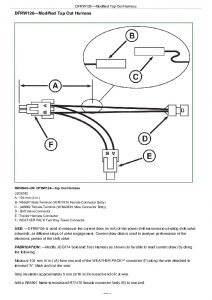
DFRW126—Modified Tap Out Harness…1568
DFRW133—Tap Out Harness…1570
Group 10: Service Tools and Kits…1563
AR94522—ISO SCV Coupler…1572
JDG774—Solenoid Test Harness…1573
JT02051—Manifold with Gauges…1574
JT02081 — Halogen Leak Detector…1575
JT02153 — Current Clamp-On Probe…1576
JT03043—Adapter 1/2 M NPT x 1-1/16 M 37°…1577
JT03044—Adapter 3/4 M NPT x 1-1/16 M 37°…1578
JT03051—Adapter 1-1/16 F 37° x 1-1/16 F 37°…1579
JT03059—90° Elbow, 1 1/16-12 M 37° x 1 1/16-12 F 37° Sw…1580
JT03110—Adapter…1581
JT03262—Adapter…1582
JT03345—Gauge…1583
JT03364—Hose with Coupler…1584
JT03367—Connector…1585
JT03481—Kit…1586
JT03481-1—Adapter Male Quick Coupler Plug x 1/4 M NPT…1587
JT03481-3—Straight Fitting 3/4-14 F NPT x M20 x 1.5 ORB…1588
JT03481-4—Straight Fitting 1/8 M BSPT X 1/8 F NPT…1589
JT03520—Special Adapter…1590
JT05473—Gauge w/Quick Coupler, 0-35,000 kPa (0-5000 psi)…1591
JT05483—Elbow 7/16-20 M 37 X 7/16-20 F 37 Sw…1592
JT05494—7/16-20 M 37° x 3/4-16 M ORB…1593
JT05498—Hose 508 mm (20 in.)…1594
JT05634—Pressure Gauge…1595
JT05685—Battery Load Tester…1596
JT05791—Digital Multimeter…1597
JT05843 — Hydrometer…1598
JT07032—Gauge 400 kPa (60 psi)…1599
JT07041—Gauge 2800 kPa (400 psi)…1600
JT07148—Digital Hydraulic Tester…1601
LVB24862—Wiring Harness…1602
RE200690—Performance Monitor…1603

John Deere Tractors 5325N, 5425N, 5525N Diagnosis & Tests Technical Manual (TM2198)


INSTANT DOWNLOAD


Posted on

John Deere 5325N, 5425N and 5525N Tractors Operator’s Manual (OMRE224589)


INSTANT DOWNLOAD


Complete Operator’s Manual for John Deere 5325N, 5425N and 5525N Tractors.

OMRE224589 English – John Deere 5325N, 5425N and 5525N Tractors Operator’s Manual (North American).pdf
omre224590 Spanish – Manual del operador de tractores 5325N, 5425N y 5525N (Norteamérica)
omre224591 French – Livret d’entretien des tracteurs 5325N, 5425N et 5525N (Amérique du Nord)
omsu32985 English – 5425N Tractor, Operator’s Manual (Argentina Edition, May 2013)

PRODUCT DETAILS:
Total Pages: 573 pages
File Format: PDF (Internal Links, Bookmarked, Table of Contents, Searchable, Printable, high quality)
Language: English

TABLE OF CONTENTS
Section 05: Safety….16
Recognize Safety Information….18
Understand Signal Words….19
Follow Safety Instructions….20
Prevent Machine Runaway….21
Use Seat Belt and Foldable ROPS Properly—Open Station….22
Operating the Tractor Safely….24
Use Caution on Hillsides….171
Shift to Low Gear on Hills….27
Avoid Tipping….28
Freeing a Mired Machine….186
Work In Ventilated Area….359
Stopping and Parking Tractor….32
Keep Riders Off Machine….33
Handle Fuel Safely—Avoid Fires….34
Prepare for Emergencies….35
Do Not Use Starting Fluid….36
Handle Starting Fluid Safely (5425N and 5525N Without Optional Starting Aid)….37
Wear Protective Clothing….38
Protect Against Noise….39
Handle Agricultural Chemicals Safely….40
Avoid Contact with Pesticides….42
Stay Clear of Rotating Drivelines….43
Use Safety Lights and Devices….44
Use a Safety Chain….45
Safely Transporting the Tractor….46
Transport Towed Equipment at Safe Speeds….47
Keep ROPS Installed Properly….49
Practice Safe Maintenance….50
Service Tractor Safely….358
Support Machine Properly….52
Remove Paint Before Welding or Heating….53
Avoid Heating Near Pressurized Fluid Lines….54
Avoid High-Pressure Fluids….55
Service Cooling System Safely….56
Handling Halogen Light Bulbs Safely….480
Store Attachments Safely….58
Handling Batteries Safely….59
Service Tires Safely….296
Dispose of Waste Properly….62
Section 10: Safety Signs….63
Replace Damaged or Missing Safety Signs….64
Safety Signs—All….65
Safety Signs—ROPS….70
Safety Signs—Open Station….71
Safety Signs—Cab….74
Safety Signs—Mid-Mount and Deluxe Rear SCV (If Equipped)….81
Section 15: Controls and Instruments….83
Front Console Switches and Controls—Open Station….84
Front Console Switches and Controls—Cab….85
Front Console Switches and Controls—Options (If Equipped)….86
Foot Operated Controls….87
Operator Station Side Controls….88
Multi-Function Control Lever (If Equipped)….90
Ignition Switch….91
Gauges and Indicator Lights….92
Roof Mounted Switches and Controls (Cab)….93
EH Hitch Raise/Lower Switches—External….94
Section 20: Lights….95
Light Identification—Open Station….96
Light Identification—Cab….98
Positioning Warning Lights for Transport (Open Station)….100
Operating Lights….101
Using Turn Signals….104
Using Seven-Terminal Outlet….105
Adjusting Rear Facing Work Light—Open Station….107
Adjusting Work Lights—Cab….108
Operating Loader Lights (If Equipped)….109
Operating Rotating Beacon Light (If Equipped)….111
Section 25: Operator Station….112
Operating Foldable ROPS….113
Using Emergency Exit (Cab)….115
Opening Rear Window (Cab)….116
Using Seat Belt….117
Adjusting Seat….118
Adjusting Steering Wheel Tilt and Height (Cab)….120
Adjusting Blower Speed….121
Controlling Temperature….122
Optimizing A/C and Heater Performance….123
Operating Windshield Wiper and Washer….124
Operating Rear Window Wiper and Washer (If Equipped)….125
Accessory Electrical Outlet….126
Using Dome Light….127
Using Controls Illumination Light….128
Installing a Monitor….129
Using Storage Compartment….130
Operating Radio (If Equipped)….131
Operating Radio with Cassette Tape Player (If Equipped)….133
Operating Radio with Compact Disc Player (If Equipped)….135
Operating Cassette Tape Player (If Equipped)….137
Operating Compact Disc Player (If Equipped)….138
Setting Clock (If Equipped)….139
Section 30: Break-In Period….140
Observe Engine Operation Closely….141
Break-In Service….349
Section 35: Prestarting Checks….143
Service Daily Before Start-Up….144
Section 40: Operating Engine….146
Before Starting the Engine….150
Starting the Engine….150
Using Engine Coolant Heater….154
Checking Engine Indicators and Gauges….156
Changing Engine Speeds….158
Recommended Engine Speeds and Operating Procedures….159
Stopping the Engine….161
Using a Booster Battery or Charger….162
Section 45: Driving and Transporting Tractor….164
Towing Loads and Transporting with Ballast….165
Towing Loads….166
Using Safety Chain….167
Driving on Public Roads….168
Use Caution on Hillsides….171
Operating PowrReverser™ Transmission….172
Operating PowrReverser™ Transmission with Hi/Lo (If Equipped)….174
PowrReverser™ Indicators….176
Ground Speed Estimates—PowrReverser™ Transmission (Specifications and design subject to change without notice.)….164
Ground Speed Estimates—PowrReverser™ Transmission with Hi/Lo (Specifications and design subject to change without notice.)….164
Using Infinitely Variable Shuttle (If Equipped)….179
Selecting a Gear….180
Correction Factors for Other Tire Sizes….181
Using Brakes….182
Using Differential Lock….183
Using Mechanical Front-Wheel Drive (MFWD)—Electro-Hydraulic Control with Auto Engage and Brake Assist (If Equipped)….184
Freeing a Mired Machine….186
Stopping the Tractor….188
Transporting on Carrier….190
Towing Tractor….191
Section 50: Rockshaft Controls….195
Rockshaft Controls….195
Using External Raise and Lower Switches….197
Adjusting Raise Height….199
Transporting Implements….200
Adjusting Rate-of-Drop….201
Adjusting Depth Stop….202
Adjusting Load/Depth Control….203
Using Position Control Setting….204
Using Draft Control….205
Using Float Control….207
Manually Lowering Hitch….208
Electro-Hydraulic Hitch Indicator….210
Section 65: Drawbar and PTO….261
Match Tractor Power to Implement….262
Observing Drawbar Load Limitations….263
Selecting Drawbar Position….264
Adjusting Drawbar Length and Offset….265
Reversing 540/1000 RPM PTO Stub Shaft (If Equipped)….266
Attaching PTO-Driven Implement….268
Selecting Correct PTO Speeds….270
Operating Tractor PTO….272
Section 60: Hydraulic System Controls and Operations….225
Hydraulic Valves….226
SCV Control Lever and Coupler Identification….229
Mid-Mount Valve Coupler Identification (If Equipped)….231
Use Correct Hose Tips….232
Connecting Cylinder Hoses—Rear SCV….233
Connecting Cylinder Hoses—Mid-Mount Valve (If Equipped)….236
Connecting Hose Under Pressure….238
Connecting and Operating Single-Acting Cylinder….239
Operating SCV Control Levers—Basic Valve….240
Setting Detents and Operating SCV Control Levers—Deluxe Valve (If Equipped)….241
Using Rear SCV to Operate Hydraulic Motor….244
Using Deluxe SCV to Operate Loader….246
Operating Multi-Function Control Lever (If Equipped)….248
Adjusting Flow Control—Deluxe SCV (If Equipped)….251
Correcting Reversed Cylinder Response….252
Warming Transmission-Hydraulic System Oil….253
Using Power Beyond Attachment (If Equipped)….256
Using Hydraulic Motor Case Drain Connection (If Equipped)….257
Using Hydraulic Motor Return Connection (If Equipped)….258
Disconnecting Cylinder Hoses….259
Section 65: Drawbar and PTO….261
Match Tractor Power to Implement….262
Observing Drawbar Load Limitations….263
Selecting Drawbar Position….264
Adjusting Drawbar Length and Offset….265
Reversing 540/1000 RPM PTO Stub Shaft (If Equipped)….266
Attaching PTO-Driven Implement….268
Selecting Correct PTO Speeds….270
Operating Tractor PTO….272
Section 70: Performance Ballasting….275
Planning for Maximum Productivity….276
Selecting Ballast Carefully….277
Matching Ballast to Work Load….278
Checking for Correct Ballast….279
Measuring Wheel Slip (Manually)….280
Ballast Limitations….282
Ballasting Front End for Transport….283
Ballasting Two-Wheel Drive Tractors….284
Ballasting MFWD-Equipped Tractors….285
Determining Maximum Rear Ballast….286
Determining Maximum Front Ballast….287
Using Cast Iron Weights….288
Installing Rear Cast Iron Weights….289
Using Liquid Ballast….292
Liquid Ballast….292
Using Implement Codes….293
Section 75: Wheels, Tires and Treads….295
Service Tires Safely….296
Check Implement-to-Tire Clearance….297
Check Tire Inflation Pressure….298
Tire Inflation Pressure Charts….299
Selecting Front Tire Rolling Direction….300
Tighten Wheel/Axle Hardware Correctly….301
Tighten Bolts—Adjustable Front Axle….302
Tighten Bolts—MFWD Axle….303
Tighten Bolts—Rear Axle….304
Observe Rear Wheel Tread Width Limitations….305
Tread Settings—Two-Position Rear Wheels….306
Tread Settings—Multi-Position Rear Wheels….307
Tread Settings—Two-Position MFWD Wheels….309
Tread Settings—Adjustable Front Axle….310
Adjusting Front Axle Tread Width….312
Checking Toe-In—Adjustable Front Axle….313
Adjusting Toe-In—Adjustable Front Axle….314
Checking Toe-In—MFWD Axle….315
Adjusting Toe-In—MFWD Tractor….316
Set MFWD Steering Stops—MFWD Axle….317
Use Correct Tire Combinations….318
Tire Compatibility Chart….319
Section 80: Fuel, Lubricants and Coolant….321
Diesel Fuel….322
Handling and Storing Diesel Fuel….323
Lubricity of Diesel Fuel….324
Testing Diesel Fuel….325
Biodiesel Fuel….326
Filling Fuel Tank….328
Diesel Engine Break-In Oil (5425N and 5525N)….330
Diesel Engine Oil….331
Oil Filters….333
Diesel Engine Coolant….334
Operating in Warm Temperature Climates….336
Additional Information About Diesel Engine Coolants and Supplemental Coolant Additives….337
Testing Diesel Engine Coolant….339
Transmission and Hydraulic Oil….340
Use Correct Transmission-Hydraulic Filter Element….341
MFWD Axle Housing and Wheel Hub Oil….342
Grease….343
Mixing of Lubricants….344
Alternative and Synthetic Lubricants….345
Lubricant Storage….346
Section 85: Maintenance and Service Intervals….347
Observe Service Intervals….348
Break-In Service….349
Service Interval Chart—Daily or 10 Hours/50 Hours/First 100 Hours/First 300 Hours/300 Hours….350
Service Interval Chart—500 Hours/600 Hours/1200 Hours/Annual/2100 Hours or Two Years….351
Service—As Required….352
Raising Hood….353
Accessing Battery….354
Using High-Pressure Washers….355
Using Compressed Air….356
Section 90: General Maintenance and Inspection….357
Service Tractor Safely….358
Work In Ventilated Area….359
Clean Vehicle of Hazardous Pesticides….360
Additional Service Information….361
Inspecting Tires….362
Tubeless Tire Repair….363
Checking Neutral Start System….364
Checking Transmission PARK Position….366
Checking Brakes….367
Service Air Cleaner….368
Air Intake System Components….370
Checking Air Intake System….371
Replacing Air Cleaner Elements….372
Inspecting Elements….374
Storing Element….375
Cleaning Grille Screens, Radiator, Oil Cooler (If Equipped) or A/C Condenser (Cab)….376
Inspecting Fan Belt Tensioner….378
Replacing Fan Belt….380
Inspecting Seat Belt….389
Inspecting Tractor for Loose Hardware….390
Adjusting 540/540E PTO Lever and Linkage….391
Cleaning Cab Air Filters….394
Servicing Air Conditioner (Cab)….396
Keeping ROPS Installed Properly (Open Station)….398
Keeping Cab Protection System Installed Properly….400
Cleaning Engine Crankcase Vent Tube….402
Checking Hoses and Hose Clamps for Tightness….403
Checking Front Axle Pivot Pin End Play….404
Adjusting Engine Valve Clearance (5425N and 5525N)….405
Section 95: Lubrication….406
Use Correct Lubricant….407
Checking Engine Oil Level….408
Changing Engine Oil and Filter—5325N….410
Changing Engine Oil and Filter—5425N and 5525N….412
Checking Transmission-Hydraulic System Oil Level….414
Replacing Transmission-Hydraulic Filter….416
Changing Transmission-Hydraulic Oil and Filter….417
Cleaning Transmission-Hydraulic Oil Pickup Screen….419
Checking MFWD Axle Wheel Hub Oil Level….421
Changing MFWD Axle Wheel Hub Oil….422
Checking MFWD Axle Housing Oil Level….423
Changing MFWD Axle Housing Oil….424
Lubricate as Necessary….426
Lubricating Steering Spindles and Steering Cylinder Ends (Adjustable Front Axle)….427
Lubricating Steering King Pins (MFWD)….428
Lubricating Front Axle Pivot Pin….429
Packing Front Wheel Bearings (Adjustable Front Axle)….430
Lubricating Rear Axle Bearings….431
Lubricating 3-Point Hitch….432
Lubricating Operator's Seat Slide Rails (Open Station)….433
Lubricating Hood Latch….434
Section 100: Maintenance—Cooling System….435
Engine Cooling System Components….436
Checking Coolant Level….437
Testing Coolant….439
Winterize Cooling System….440
Flushing Cooling System and Replacing Thermostat….441
Section 101: Maintenance—Fuel System….442
Do Not Modify Fuel System….443
Fuel System Components—5325N….444
Fuel System Components—5425N and 5525N….445
Drain Water and Sediment from Fuel Tank and Fuel Filter….446
Replacing Fuel Filter—5325N….448
Replacing Fuel Filter—5425N and 5525N….449
Replacing In-Line Fuel Filter….450
Bleeding Fuel System—5325N….451
Bleeding Fuel System—5425N and 5525N….453
Inspecting Fuel Injectors (5425N and 5525N)….455
Checking Engine Idle Speeds….456
Adjusting Hand Throttle Friction….457
Section 102: Maintenance—Electrical System….458
Prevent Battery Explosions….459
Observe Electrical Service Precautions….460
Cleaning and Checking Battery….461
Removing Battery….462
Servicing Battery….463
Battery Replacement Specifications….466
Charging Battery….467
Checking Battery Condition….468
Connecting Starter Wiring….469
Connecting Alternator Wiring….470
Locating Fusible Links….471
Locating Fuses—Open Station….472
Locating Fuses—Cab….474
Fuse and Relay Size and Function—Open Station….476
Fuse and Relay Size and Function—Cab….478
Handling Halogen Light Bulbs Safely….480
Adjusting Headlights….481
Replacing Headlight Bulb….483
Replacing Warning Light Bulb—Open Station….485
Replacing Warning Light Bulb—Cab….486
Replacing Taillight Bulb….487
Replacing Work Light Bulb—Open Station….488
Replacing Work Light Bulb—Cab….489
Replacing Loader Light Bulb (If Equipped)….491
Replacing Dome Light Bulb (Cab)….493
Replacing Controls Illumination Light Bulb (Cab)….494
Replacing Rotary Beacon Light Bulb (Cab) (If Equipped)….495
Section 105: Troubleshooting….497
Engine Troubleshooting….498
Transmission Troubleshooting….503
Hydraulic System Troubleshooting….504
Brakes Troubleshooting….505
Rockshaft and 3-Point Hitch Troubleshooting….506
Deluxe Selective Control Valve Troubleshooting (If Equipped)….509
Remote Hydraulic Cylinder Troubleshooting….510
Electrical System Troubleshooting….511
Heater and A/C System Troubleshooting (Cab)….513
Wipers, Work Lights, Dome Light and Radio Troubleshooting (Cab)….517
Section 110: Storage….518
Storing Tractor….519
Removing Tractor From Storage….524
Section 115: Specifications….525
Machine Specifications (Specifications and design subject to change without notice.)….525
Drain and Refill Capacities (Specifications and design subject to change without notice.)….525
Machine Dimensions—Open Station (Specifications and design subject to change without notice.)….525
Machine Dimensions—Cab (Specifications and design subject to change without notice.)….525
Permissible Load Specifications (Specifications and design subject to change without notice.)….525
Metric Bolt and Screw Torque Values….535
Unified Inch Bolt and Screw Torque Values….537
Limited Battery Warranty….539
Section 120: Identification Numbers….542
Identification Numbers….542
Record Tractor Identification Number….543
Record Front Axle Serial Number….544
Record Engine Serial Number….545
Record Transmission Serial Number….546
Record Cab Serial Number….547
Keep Proof of Ownership….548
Keep Machines Secure….549
Section 125: Lubrication and Maintenance Records….550
10-Hour Service Chart….551
50-Hour Service Chart….552
First 100 Hours Service Chart….553
First 300 Hours Service Chart….554
300-Hour Service Chart….555
500-Hour Service Chart….556
600-Hour Service Chart….557
1200-Hour Service Chart….558
Annual Service Chart….559
2100-Hour or 2-Year Service Chart….560
As Required Service Chart….561

John Deere 5325N, 5425N and 5525N Tractors Operator’s Manual (OMRE224589)


INSTANT DOWNLOAD