Posted on

Deutz-Fahr AGROPLUS 60, AGROPLUS 70, AGROPLUS 80 Repair Service Manual


INSTANT DOWNLOAD


Complete service manual for Deutz-Fahr AGROPLUS 60, AGROPLUS 70, AGROPLUS 80, with workshop information to maintain, diagnose, repair, and rebuild like professional mechanics.

Deutz-Fahr Tractors AGROPLUS 60, AGROPLUS 70, AGROPLUS 80 workshop service repair manual includes:
* Numbered table of contents easy to use so that you can find the information you need fast.
* Detailed sub-steps expand on repair procedure information
* Numbered instructions guide you through every repair procedure step by step.
* Troubleshooting and electrical service procedures are combined with detailed wiring diagrams for ease of use.
* Notes, cautions and warnings throughout each chapter pinpoint critical information.
* Bold figure number help you quickly match illustrations with instructions.
* Detailed illustrations, drawings and photos guide you through every procedure.
* Enlarged inset helps you identify and examine parts in detail.

307.1064.3.6 – Deutz-Fahr AGROPLUS 60, AGROPLUS 70, AGROPLUS 80 Workshop Manual.pdf

Total Pages: 509 pages
File Format: PDF
Language: English

TABLE OF CONTENTS
List of contents
Tractor configurations AGROPLUS 60 – 70 – 80 ..6
Dimensions and weights..7
Prescribed lubricants and capacities ..8
Conversion tables ..9
Parts ..10
1 – ENGINE
2 – CLUTCH
Gearshift clutch..12
General specifications ..12
Cecking clutch ..16
Adjusting clutch control pedal ..16
Bleeding air from the hydraulic circuit..16
Stripping the slave cylinder..17
Stripping the master cylinder ..18
Diagnosing malfunctions ..20
POWERSHIFT unit, general specifications ..21
POWERSHIFT unit detach from the gear box ..24
Assembly of POWERSHIFT unit ..35
Re-assembly of the POWERSHIFT unit. ..37
Fitting the oil manifolds of the POWERSHIFT unit ..39
Diagnosing malfunctions ..44
3 – TRANSMISSION
General specifications ..45
Technical specifications ..45
Speed change configurations ..47
Section through transmission ..51
Section through transmission with POWERSHIFT unit ..52
Separating the front gearbox from the engine ..61
Dismantling the gearbox ..62
Removal of the gearbox input and P.T.O. shafts ..62
Separating the POWERSHIFT unit from the gearbox ..62
Removal of the gear train positioned in the front gearbox ..63
Disassembly of the inversor control rods and forks ..64
Dismantling of the gearchange rod and fork assembly ..65
Dismantling of the gearchange selector rods and forks assembly ..66
Removal of the shaft with the actuator for engagement/disengagement of the front-wheel drive ..67
Removal of the range gear shaft .. 67
Examining parts removed ..68
Adjusting play of the gearbox shafts by means of the thrust plates on the mini/inversor
shaft and the secondary shaft ..69
Warnigns related to assembly of the gears of the P.T.O. unit, the range reduction unit and synchronised
P.T.O. shaft ..73
Assembly of the P.T.O. ..73
Installation of the range reduction unit, the gear for the front-wheel drive shaft
and the parking brake discs..73
Points where sealant is to be used ..75
Tightening torques ..78
Bevel drive adjustment ..81
Servicing operations ..82
Rear power take-off ..83
P.T.O. clutch ..88
Technical specifications ..89
Correct positions of P.T.O. sensors and cables ..89
Clutch inspection ..91
Checking clutch hydraulic pressures ..92
Checking the end-play of the front shaft of the P.T.O. clutch ..93
Renewal of the rear P.T.O. clutch ..94
Main operations for removal of the rear P.T.O. unit ..95
Diagnosing malfunctions ..100
4 – AXLES
Rear axle ..101
Installing the rear half-shafts ..102
Removal and disassembly of the epicyclic reduction unit..104
Fitting lateral stub axles of the wheel ..105
2WD extendible axle..106
Removing the axle from the front support ..108
Centre steering lever ..111
Wheel hub ..112
End float adjustment ..114
Front-wheel drive..115
Specifications ..115
Epicyclic reduction unit ..119
Side hubs..121
Tightening torques..122
Adjusting bevel gears ..124
Adjustment of the internal control of the mechanical differential lock..125
Installing the differential assembly into the drive axle ..125
Diagnosing malfunctions ..126
5 – VEHICLE
Brakes – General information..127
Hydraulic pump..128
Assembly of brake master cylinder ..130
Checking the front brake disks on 2WD and 4WD front axles and the rear brake disks.. 131
Adjusting service brake pedals ..131
Correct installation of inspection cover for parking brake discs..132
Checking parking brake pads ..134
Bleeding air from the brake hydraulic system..135
“Separate Brakes” valve ..136
Diagnosing malfunctions ..140
Hydraulic lift with “load sensing” ..141
Installing the lift and front cover plate of the gearbox ..142
Lift mechanism ..142
Checking the safety valves ..142
Checking the protrusion of the non-return valve..143
Adjusting the lift ..145
Lift hydraulic circuit ..147
Sensing arm assemblyMontaggio dell’organo sensibile ..154
Power-lift distributor valve spring setting specifications ..155
Electronic lift ..156
Control panel ..157
Control level or depth control knob ..157
Mix position/draft control..157
Lowering speed control knob..158
Maximum lift height control knob ..158
Up/Down control switch ..158
Up control ..158
Control/Float mode ..158
Lift status indicator light ..158
Remote pushbuttons for lift operation from ground ..159
Lift operation ..160
List of electronic lift tests ..164
Precautions for electronic equipment ..173
Checking the electronics system ..173
Checking mechanical components ..173
Front hydraulic liftSollevatore idraulico anteriore..174
Hydraulic accumulator and antishock valve for front lift ..176
Front power take-off – General information..177
Section of the P.T.O. ..178
Fitting the “RING-FEEDER” rings..182
Checking the clutch ..183
Diagnosing malfuntions ..184
Spring specifications..184
6 – CONTROLS
Hydrostatic steering ..185
Inspections and checks ..186
Steering pump ..186
Directional control valve ..186
Check the setting of the pressure relief valve..186
Bleeding the hydraulic circuit ..186
Assembly of orbital pump unit ..186
Teering wheel shaft and steering cylinders ..187
Instructions for the hydrostatic steering distributor assembly ..189
Diagnosing malfuntions ..192
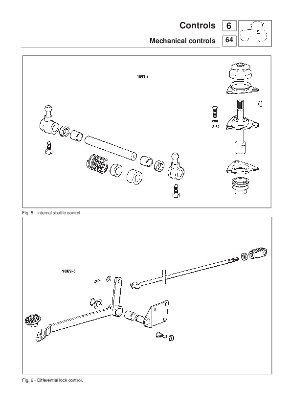
Mechanical controls ..196
Electro-hydraulic controls ..197
Front P.T.O. clutch engagement control..202
Rear P.T.O. clutch engagement control ..202
Differential lock engagement control ..202
Front-wheel drive engagement control ..202
Rear P.T.O. engagement control ..202
Gearbox ..202
Front and rear lift ..202
Hydraulic circuit diagram ..202
Solenoid valve – Specifications ..207
Adjustment of front and rear differential lock control ..214
7 – BODYWORK
Platform ..215
Cab – General information ..216
Cab air filter ..218
Screen wash ..218
Screen wipers (front and rear) ..218
Removing the driving platform complete with cab ..219
Breakage of the top hood release cable ..220
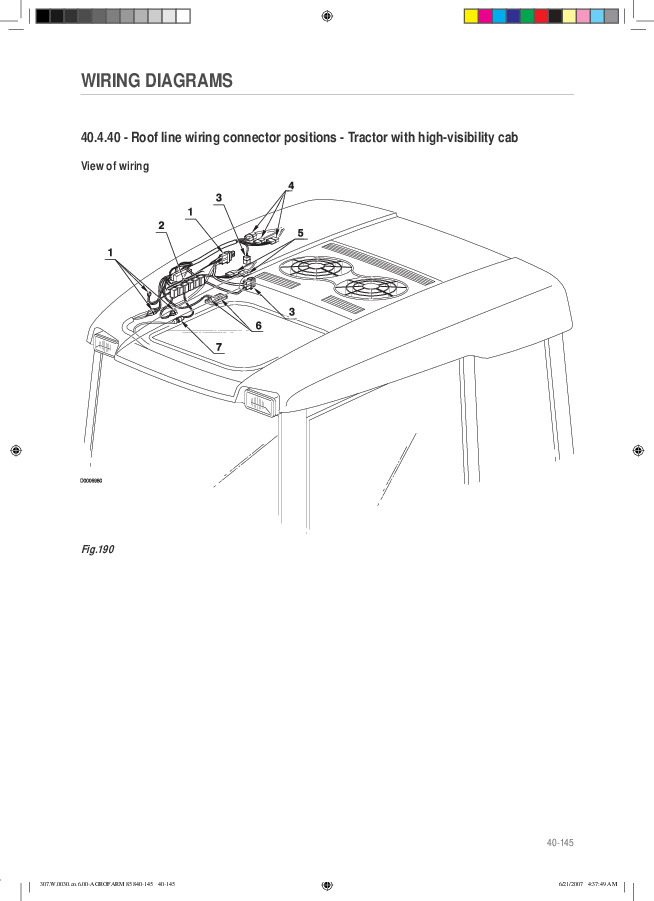
High visibility cab roof ..222
8 – SYSTEMS
Ventilation ..223
Heating System ..223
Air conditioning unit for cabs ..227
Operation and maintenance of the air-conditioning system ..228
Water dripping from the points at which condensate drain lines are connected to the conditioning unit ..229
Checking system ..231
System safety elements ..231
Temperature regulation ..231
Charging the system..232
Filling the metering unit ..232
Refilling the system with oil ..232
Verifying operation of the system after recharging ..234
Directions for tightening air conditioning system pipeline fittings ..234
Diagnosing malfuntions ..241
Hydraulic system ..242
Oil filters ..243
Hydraulic pumps ..243
Checking the relief valves of the hydraulic lift system ..243
Stripping the hydraulic pump ..244
Auxiliary hydraulic spool valves ..247
Checking the pressure relief valve setting ..250
Checking the operating pressure ..250
Conversion of auxiliary spool valves from double acting to single acting operation..250
Checking the surface of the valve spools ..250
Trailer hydraulic braking system ..251
Use of the tractor with CUNA 341/01 hydraulic trailer braking ..253
Installing the hydraulic braking valve for trailers equipped with “safety brake”
( ITALIAN version) ..258
Electrical system AGROPLUS 60 (up serial number1017) – 70 (up serial number 2773) – 80..261
Electrical system AGROPLUS 60 (under serial number 1016) – 70 (under serial number 2772) ..445
General safety directions..446
Jump start utilizing another battery..447
Recharge system..449
Heating system ..450
Starting system ..450
Ignition key ..452
Ventilation control ..452
Push button control..452
Beacon push button..454
Work ligths..454
2-Speed windscreen wiper switch ..454
Relay ..455
Electronic flasher unit ..455
Switch controlling..456
Switch controlling: differential lock – P.T.O. clutch – 4RM – 540 1000 rpm/min P.T.O. speed selector –
Economy P.T.O. – Live P.t.o. – electric starter system..456
Switch for emergency brake ..456
Fuse box ..457
Instrument panel with digital display ..458
Operation of the broken belts alarm control unit..460
Engine stop operation with a type 2MH engine control unit ..462
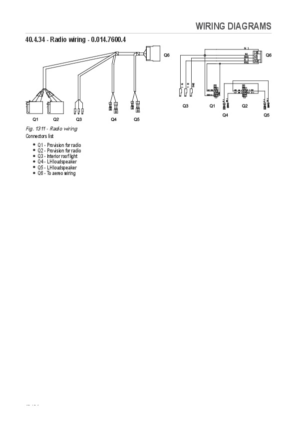
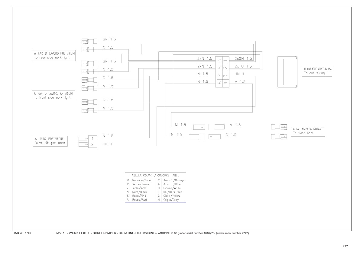
Electrical wiring..465
9 – APPENDIX
Power lift tester version 1.24a ..I

Deutz-Fahr AGROPLUS 60, AGROPLUS 70, AGROPLUS 80 Repair Service Manual


INSTANT DOWNLOAD


Posted on

Deutz-Fahr Agrokid 210, Agrokid 220, Agrokid 230 Repair Service Manual


INSTANT DOWNLOAD


Complete service manual for Deutz-Fahr Agrokid 210, Agrokid 220, Agrokid 230, with all the shop information to maintain, diagnose, repair, and service like professional mechanics.

Deutz-Fahr Tractors Agrokid 210, Agrokid 220, Agrokid 230 official workshop service repair manual includes:
* Numbered table of contents easy to use so that you can find the information you need fast.
* Detailed sub-steps expand on repair procedure information
* Numbered instructions guide you through every repair procedure step by step.
* Troubleshooting and electrical service procedures are combined with detailed wiring diagrams for ease of use.
* Notes, cautions and warnings throughout each chapter pinpoint critical information.
* Bold figure number help you quickly match illustrations with instructions.
* Detailed illustrations, drawings and photos guide you through every procedure.
* Enlarged inset helps you identify and examine parts in detail.

307.W.0430.EN.6.02 – Deutz-Fahr Agrokid 210, Agrokid 220, Agrokid 230 Workshop Manual.pdf

Agrokid 210 ->20001
Agrokid 220
->ZKDS2102V0MD20001
Agrokid 220
->ZKDS2902V0MD20001
Agrokid 230
->ZKDS2202V0MD20001
Agrokid 230
->ZKDS3002V0MD20001

Total Pages: 488 pages
File Format: PDF (bookmarked, Searchable, Printable, high quality)
Language: English

TABLE OF CONTENTS
0 – Introduction
0.1 – Introduction
0.1.1 – Safety notes
0.1.2 – General safety rules
0.1.3 – Safety precautions for removal and refitting operations
0.1.4 – Lifting instructions
0.1.5 – Tightening torques
0.1.6 – Threadlockers, adhesives, sealants and lubricants
0.1.7 – Conversion factors
10 – Technical characteristics
10.1 – Transmission
10.1.1 – Transmission
10.1.2 – Rear PTO and Mid PTO
10.2 – Rear axle
10.2.1 – Brakes and rear axle assembly
10.3 – Front axle
10.3.1 – Front axle
10.4 – Hydraulic system
10.4.1 – Gear pump
10.4.2 – Differential lock control assembly
10.4.3 – Steering circuit
10.4.4 – Power steering valve
10.4.5 – Remote control valve
20 – Calibrations and electronic diagnosis
20.1 – Diagnostic tool screens
20.1.1 – Baruffaldi electromagnetic clutch
20.1.2 – Operator seated sensor ECU (p/n 2.8519.106.0)
30 – Method of intervention
30.1 – B0 – Engine
30.1.1 – PREPARATION FOR DISASSEMBLY
30.1.2 – Engine – Separation from the transmission
30.1.3 – Engine
30.1.4 – Compression test
30.1.5 – engine block, crankshaft, pistons and sump
30.1.6 – Inspection of the engine monobloc
30.1.7 – Inspection of the crankshaft
30.1.8 – Fan – alternator drivebelt
30.1.9 – A/C fan – compressor drivebelt
30.1.10 – Crankshaft pulley
30.1.11 – Flywheel bearing
30.1.12 – Timing gears and flywheel
30.1.13 – Inspection of the flywheel and ring gear
30.1.14 – Inspection of the pistons, piston rings and gudgeon pins
30.1.15 – Inspection of the connecting rods
30.1.16 – Inspection of the camshaft
I30.1.17 – Inspection of the camshaft
30.1.18 – Inspection of the idler gear
30.1.19 – Inspection of the valves, valve guides and valve seats
30.1.20 – Valve clearances
30.1.21 – Inspection of the rocker arms and rocker shaft
30.1.22 – Cylinder head and valve train components
30.1.23 – Inspection of the cylinder head
30.1.24 – Inspection of the valve springs
30.1.25 – Inspection of the valve pushrods
30.1.26 – Renewal of the jets
30.1.27 – Lubrication System
30.1.28 – Inspection of the lubrication system
30.1.29 – Fuel System
30.1.30 – Inspection and adjustment of the fuel system
30.1.31 – Inspection of the fuel lift pump
30.1.32 – Injection pump
30.1.33 – Inspection of the fuel injection pump camshaft
30.1.34 – Inspection of the fuel injection pump camshaft
30.1.35 – Fuel injection nozzle
30.1.36 – Maintenance of the injector nozzles
30.1.37 – Governor
30.1.38 – Cooling system
30.1.39 – Inspection of the cooling system
30.1.40 – Engine air intake pipe
30.1.41 – Intake and exhaust systems
30.1.42 – Inspection of the air intake and exhaust system
30.2 – C0 – Engine accessories
30.2.1 – Engine cooling system radiator
30.2.2 – Expansion tank
30.2.3 – Fan
30.2.4 – Air cleaner assembly
30.2.5 – Fuel filter
30.2.6 – Fuel tank – Fuel tank float switch
30.2.7 – Auxiliary fuel tank
30.2.8 – Engine stop keyswitch
30.2.9 – Exhaust pipe – tractor with cab
30.2.10 – Engine stop keyswitch
30.2.11 – Alternator
30.2.12 – Alternator
30.2.13 – Starter motor
30.2.14 – Starter motor
30.2.15 – Disassembly of the starter motor
30.3 – D0 – Transmission
30.3.1 – Clutch plate
30.3.2 – Checking clutch plate wear
30.3.3 – Clutch release bearing
30.3.4 – Clutch release forks
30.3.5 – Clutch housing
30.3.6 – Disassembly of the gearbox input shaft
30.3.7 – Disassembly of the main shaft
30.3.8 – Disassembly of the secondary shaft
30.3.9 – Gearbox and shuttle assembly – complete unit
30.3.10 – Gearbox and shuttle assembly – complete unit
30.3.11 – Range gearbox and differential assembly – complete unit
30.3.12 – Gearbox input shaft – oil seal renewal
30.3.13 – Bevel gear pair
30.3.14 – Disassembly of 4WD output shaft and groundspeed PTO
30.3.15 – Creeper – synchronizer renewal
30.3.16 – PTO output shaft.
30.3.17 – Disassembly of the PTO output shaft.
30.3.18 – Removal of the PTO output shaft
30.3.19 – Parking brake
30.3.20 – Adjustment of the bevel gear pair
30.4 – E0 – Rear axle
30.4.1 – Left-hand rear axle
30.4.2 – Disassembly of LH/RH rear axle
30.4.3 – Rear differential
30.4.4 – Disassembly of the rear differential
30.4.5 – Rear axle brake discs
30.5 – F0 – Front axle
30.5.1 – Front support
30.5.2 – Front axle – complete assembly
30.5.3 – Steering cylinders
30.5.4 – Steering cylinders disassembly
30.5.5 – Steering knuckle housing and axle shaft
30.5.6 – Disassembly of the bevel gear pair
30.5.7 – Propeller shaft – Front axle drive shaft
30.5.8 – Planetary reduction gear
30.5.9 – Disassembly of the planetary reduction gear
30.6 – G0 – Bodywork – Cab – Platform
30.6.1 – Cab
30.6.2 – Hood and side panels
30.6.3 – Cab access steps
30.6.4 – Adjustable front fenders
30.6.5 – Cab door lock – tie-rod
30.6.6 – Instrument panel
30.6.7 – Left-hand rear cab pillar – screenwash reservoir
30.6.8 – Right-hand console
30.6.9 – Left-hand console
30.6.10 – Instrument panel
30.6.11 – Centre console
30.6.12 – RH rear cab pillar trim
30.6.13 – A/C system air intake filters
30.6.14 – Cab roof
30.6.15 – Seat
30.6.16 – Air conditioning system – Standard roof version
30.6.17 – Air conditioning compressor
30.6.18 – Condenser
30.6.19 – Receiver-dryer
30.6.20 – Evaporator assembly
30.6.21 – Air conditioner fan
30.6.22 – Bistable pressure switch for compressor clutch engagement/disengagement
30.6.23 – Steering wheel
30.6.24 – Adjustment of the lift control valve levers
30.6.25 – Remote valve control levers
30.7 – H0 – Hydraulic system
30.7.1 – Pump for hydraulic lift and auxiliary services and power steering system
30.7.2 – Transmission oil filter assembly
30.7.3 – Power steering valve – Complete assembly
30.7.4 – Power steering disassembly
30.7.5 – Pressure relief valve – lift control valve
30.7.6 – Lift locking shut-off valve
30.7.7 – Remote control valve
30.7.8 – Remote control valve
30.7.9 – Control rods
30.7.10 – Double/single acting conversion valve
30.8 – L0 – Electrical system
30.8.1 – Battery
30.8.2 – Fuse and relay assembly
30.8.3 – Electrostatic unit
30.8.4 – Parking brake switch
30.8.5 – Adjustment of the parking brake switch
30.8.6 – Brake lights switches
30.8.7 – Adjustment of the brake light switches
30.8.8 – Steering column switch
30.8.9 – Control buttons – RH console
30.9 – M0 – Front PTO
30.9.1 – Pump – clutch assembly – brake
30.9.2 – PTO output shaft
30.9.3 – Solenoid valve
30.10 – N0 – Front lift
30.10.1 – Front lift – version with front PTO –
30.10.2 – Cylinder
30.11 – R0 – Rear lift
30.11.1 – Rear lift – complete assembly
30.11.2 – Rear lift – complete assembly
30.11.3 – Adjustment of the rear lift
30.11.4 – Lift cylinders
30.11.5 – Lift cylinders
30.11.6 – Renewal of the rear lift bush
30.11.7 – Lift arms
30.11.8 – Hydraulic lift control valve
30.11.9 – Disassembly of the lift control valve
30.11.10 – Three-point linkage with mechanical adjustment
30.12 – S0 – Wheels
30.12.1 – Front wheels
30.12.2 – Rear wheels
30.13 – V0 – Ballast – towing hitches
30.13.1 – Support and towing hitch
40 – Wiring diagrams
40.1 – Introduction
40.1.1 – Structure of the unit
40.1.2 – Wiring and components index
40.1.3 – Introduction
40.1.4 – Basic electronics for mechanics (1/2)
40.1.5 – Basic electronics for mechanics (2/2)
40.1.6 – Electrical and electronic components (1/2)
40.1.7 – Electrical and electronic components (2/2)
40.2 – Components
40.2.1 – Components
40.3 – Systems
40.3.1 – Earthing points
40.3.2 – Starting
40.3.3 – Control unit – Fan
40.3.4 – Steering column lights switch
40.3.5 – Instrument panel
40.3.6 – Cab
40.3.7 – Aereo cab
40.3.8 – PTO
40.3.9 – Front axle differential lock
40.3.10 – Brakes
40.4 – Wiring harnesses
40.4.1 – Wiring harnesses
40.4.2 – Positions of front wiring connectors
40.4.3 – Front PTO wiring – 0.014.2645.4
40.4.4 – Positions of front PTO wiring connectors.
40.4.5 – Front lights wiring – 0.014.7599.4
40.4.6 – Positions of front light wiring connectors
40.4.7 – Compressor wiring – 0.014.7601.4
40.4.8 – Positions of compressor wiring connectors
40.4.9 – Front wiring with cab
40.4.10 – Positions of front wiring connectors with cab
40.4.11 – Central wiring – 0.012.6949.4
40.4.12 – Positions of central wiring connectors
40.4.13 – Solenoid valve wiring – 0.014.1482.4
40.4.14 – Positions of solenoid valve wiring connectors
40.4.15 – Rear wiring – 0.013.1452.4/10
40.4.16 – Positions of rear wiring connectors
40.4.17 – Remote valve wiring – 0.012.6955.4
40.4.18 – Rear lights wiring – 0.014.7602.4
40.4.19 – Positions of rear light wiring connectors
40.4.20 – Aereo cab wiring – 0.014.7593.4
40.4.21 – Positions of aereo-cab wiring connectors
40.4.22 – Cab power supply – 0.014.7594.4
40.4.23 – Positions of cab power supply wiring connectors
40.4.24 – Air conditioning system – 0.014.7596.4
40.4.25 – Position of air conditioner wiring connectors
40.4.26 – Cab earth wiring – 0.015.0031.4
40.4.27 – Positions of cab earth wiring connectors
40.4.28 – Worklights-number plate light- flashing light – 0.014.7595.4
40.4.29 – Positions of worklight, number plate and flashing light wiring connectors
40.4.30 – Flashing light wiring – 0.014.7591.4
40.4.31 – Positions of flashing light wiring connectors
40.4.32 – Windscreen wipers – 0.014.7598.4
40.4.33 – Positions of windscreen wiper wiring connectors
40.4.34 – Radio wiring – 0.014.7600.4
40.4.35 – Positions of radio-loudspeaker wiring connectors

Deutz-Fahr Agrokid 210, Agrokid 220, Agrokid 230 Repair Service Manual


INSTANT DOWNLOAD


Posted on

Deutz-Fahr Agrokid 30, Agrokid 40, Agrokid 50 Repair Service Manual


INSTANT DOWNLOAD


Complete repair service manual for Deutz-Fahr Agrokid 30, Agrokid 40, Agrokid 50, with workshop information to maintain, diagnose, repair, and service like professional mechanics.

Deutz-Fahr Tractors Agrokid 30, Agrokid 40, Agrokid 5 workshop service repair manual includes:
* Numbered table of contents easy to use so that you can find the information you need fast.
* Detailed sub-steps expand on repair procedure information
* Numbered instructions guide you through every repair procedure step by step.
* Troubleshooting and electrical service procedures are combined with detailed wiring diagrams for ease of use.
* Notes, cautions and warnings throughout each chapter pinpoint critical information.
* Bold figure number help you quickly match illustrations with instructions.
* Detailed illustrations, drawings and photos guide you through every procedure.
* Enlarged inset helps you identify and examine parts in detail.

307.W.0430.EN.6.02 – Deutz-Fahr Agrokid 30, Agrokid 40, Agrokid 50 Workshop Manual.pdf

PRODUCT DETAILS:
Total Pages: 430 pages
File Format: PDF (bookmarked, Searchable, Printable, high quality)
Language: English

1. TRANSMISSION
2. FRONT AXLE
3. CONTROLS
4. HYDRAULIC SYSTEM

307.1108.3.6 AGROKID 30-40-50…1
INTRODUCTION…3
SAFETY NOTES…5
SAFETY PRECAUTIONS FOR REMOVAL AND REFITTING OPERATIONS…8
LIFTING INSTRUCTIONS…10
HOW THE MANUAL IS STRUCTURED…11
HOW TO CONSULT THE MANUAL…12
HOW TO USE AND UPDATE THE MANUAL…13
STANDARD TIGHTENING TORQUES FOR NUTS AND BOLTS…14
THREADLOCKERS, ADHESIVES, SEALANTS AND LUBRICANTS…15
CONVERSION FACTORS…17
SECTION 10…19
1. TRANSMISSION…21
1.1 INTRODUCTION…21
1.2 DESCRIPTION…22
1.2.1 DRIVE TRANSMISSION…23
1.3 CLUTCH HOUSING…24
1.4 GEARBOX AND SHUTTLE ASSEMBLY…25
1.5 4WD RANGE GEARS ASSEMBLY…26
1.6 PINION AND DIFFERENTIAL ASSEMBLY…27
1.7 BRAKES AND REAR AXLE ASSEMBLY…28
1.8 REAR PTO AND MID PTO…29
1.8.1 COMPONENTS…29
1.8.2 MAIN COMPONENTS…30
2. FRONT AXLE…31
2.1 STEERING CYLINDER…32
2.2 DIFFERENTIAL- PINION – FINAL DRIVE UNIT…33
3. CONTROLS…34
3.1 RIGHT-HAND SIDE VIEW…34
3.2 LEFT-HAND SIDE VIEW…35
3.3 TOP VIEW…36
4. HYDRAULIC SYSTEM…37
4.1 DESCRIPTION…37
4.2 HYDRAULIC DIAGRAM…38
4.3 STEERING CIRCUIT…39
4.3.1 FUNCTION…39
4.3.2 OPERATION…39
4.3.3 GEAR PUMP…40
4.3.4 POWER STEERING…41
4.3.5 DIFFERENTIAL LOCK CONTROL ASSEMBLY…43
4.3.6 AUXILIARY SERVICES CONTROL VALVE (4 WAYS)…45
4.3.7 POWER LIFT CONTROL VALVE…46
SECTION 30…53
ENGINE HOOD…55
Removal…55
Refitting…55
SAFETY ROLL BAR…56
Removal…56
Refitting…56
SILENCER…57
Removal…57
Refitting…58
RADIATOR…59
Removal…59
Refitting…61
FRONT SUPPORT…62
Removal…62
Refitting…64
WHEELS…65
FRONT WHEELS…65
Removal…65
Refitting…65
REAR WHEELS…66
Removal…66
Refitting…66
INSTRUMENT PANEL…67
Removal…67
Refitting…68
CONSOLE SHROUDS…69
Removal…69
Refitting…70
POWER STEERING…71
Removal…71
Refitting…72
FUEL TANK…73
Removal…73
Refitting…74
PLATFORM…75
Removal…75
Refitting…77
STARTER MOTOR…78
Removal…78
Refitting…80
HYDRAULIC PUMP…81
Removal…81
Refitting…81
ALTERNATOR…82
Removal…82
Refitting…83
Tensioning the drivebelt…83
ENGINE…85
Separating the engine from the transmission…85
Reconnecting the engine to the transmission…90
Removal…91
Refitting…95
CLUTCH ASSEMBLY…96
PTO CLUTCH…96
Removal and renewal of the PTO clutch plate…96
Check PTO clutch plate wear…96
Refitting the PTO clutch plate…96
Adjustment of the clutch levers…97
PTO DRIVE SHAFT OIL SEAL…98
Renewal…98
CLUTCH RELEASE BEARINGS…99
Removal…99
Refitting…101
LIFT…102
COMPLETE ASSEMBLY…102
Removal…102
Refitting…103
POWER LIFT CONTROL VALVE…104
Removal…104
Refitting…105
Disassembly…106
Assembly…109
CYLINDER…111
Disassembly…111
Assembly…112
LIFT ARM OIL SEAL…113
Removal…113
Refitting…115
BUSHES…116
Renewal…116
INTERNAL LINKAGE…117
Removal…117
Refitting…118
HYDRAULIC LEVER LIMIT…119
Adjustment…119
LIFT CONTROL VALVE…120
Disassembly…120
Assembly…121
AUXILIARY SERVICES CONTROL VALVE (4 WAYS)…122
AUXILIARY SERVICES CONTROL VALVE…122
Removal…122
Refitting…122
CONTROL RODS…123
Disassembly…123
Assembly…123
DOUBLE/ SINGLE ACTING CONVERTER…124
Overhaul…124
CLUTCH HOUSING…125
Separation from the transmission…125
Reconnection to the transmission…130
GEARBOX AND SHUTTLE ASSEMBLY…131
COMPLETE ASSEMBLY…131
Removal…131
Refitting…132
Disassembly…133
Assembly…135
INPUT SHAFT…137
Disassembly…137
Assembly…138
PRIMARY SHAFT…139
Disassembly…139
Assembly…139
SECONDARY SHAFT…140
Disassembly…140
Assembly…143
GEAR SELECTOR FORKS…144
Check flatness…144
REAR AXLE AND BRAKES…145
REAR AXLE…145
Removal…145
Refitting…146
Disassembly…147
Assembly…149
BRAKE…153
Renewal of the braking discs…153
REAR PTO…155
Disassembly…155
Assembly…158
RANGE GEARBOX AND REAR DIFFERENTIAL ASSEMBLY…159
RANGE GEARBOX INPUT SHAFT…159
Disassembly…159
Assembly…160
DIFFERENTIAL…161
Removal…161
Refitting…162
Disassembly…163
Assembly…164
BEVEL GEAR PAIR…165
Disassembly…165
Preparation for installation…167
Adjustment of the differential preload…168
Adjustment of the pinion position…169
Adjustment of the pinion and crown wheel…172
Final assembly…173
4WD AND GROUND SPEED PTO OUTPUT SHAFT…174
Disassembly…174
Assembly…175
PEDALS AND CONTROL LEVERS…176
BRAKE PEDALS…176
Adjustment…176
PARKING BRAKE LEVER…176
Adjustment…176
CLUTCH PEDAL…177
Adjustment…177
PTO SPEED SELECTOR LEVER…177
Adjustment…177
PTO ENGAGEMENT LEVER…177
Adjustment…177
RANGE GEAR LEVER…177
Adjustment…177
MAIN GEAR LEVER…178
Adjustment…178
FRONT AXLE…179
COMPLETE AXLE ASSEMBLY…179
Removal…179
Refitting…181
BEVEL GEAR PAIR…182
Disassembly…182
Assembly…187
FINAL DRIVE REDUCTION UNITS…193
Removal…193
Refitting…193
OUTPUT FLANGE…195
Disassembly…195
Assembly…197
STEERING JOINT…198
Disassembly…198
Preparation For Assembly…200
Final assembly…202
STEERING CYLINDER…203
Disassembly…203
Assembly…206
SECTION 40…209
THE STRUCTURE OF THE UNIT…211
HOW TO CONSULT THE UNIT…212
1. INTRODUCTION…213
1.1 LIST OF WIRING LOOMS…213
1.2 DEFINITION OF COMPONENTS AND SYMBOLS…213
1.3 GENERAL RULES…214
1.3.1 MODIFICATION OF THE TRACTOR'S ELECTRICAL/ELECTRONIC CIRCUITS…214
1.3.2 MAIN WIRING FAULTS…214
1.3.3 REMOVAL, REFITTING AND DRYING OF CONNECTORS AND WIRING…215
1.4 DIAGNOSTIC INSTRUMENTS…216
1.5 WIRE COLOUR CODES…216
2. INDICES…217
2.1 INDEX BY PART DESCRIPTION…217
2.2 INDEX BY PART CODE…219
2.3 INDEX BY CONNECTOR…221
3. COMPONENTS…223
3.1 COMPONENT TECHNICAL DATA…223
3.2 PREHEATING SYSTEM…226
3.3 ENGINE STOP SYSTEM…226
4. SYSTEMS…227
4.1 EARTHING POINTS…227
4.2 STARTING…228
4.3 FRONT AXLE DIFFERENTIAL LOCK…229
4.4 LIGHTS-SWITCH UNIT-BRAKES…230
4.5 INSTRUMENT PANEL…231
5. LAYOUTS, ELECTRICAL WIRING DIAGRAMS, CONNECTOR POSITIONS…233
FRONT WIRING (1/2)…233
FRONT WIRING (2/2)…234
CENTRAL WIRING (1/2)…241
CENTRAL WIRING (2/2)…242
REAR WIRING (1/2)…253
REAR WIRING (2/2)…254
SECTION 50…259
Introduction…261
HOW TO USE THIS MANUAL…262
General information…265
MODEL IDENTIFICATION AND SERIAL NUMBER LOCATION…265
COMPONENT POSITIONS – NATURALLY ASPIRATED ENGINE (S4L/S4L2)…266
COMPONENT POSITIONS – TURBO ENGINE (S4L-T/S4L2-T)…267
SPECIFICATIONS…268
Overhaul instructions…269
DETERMINING WHEN TO OVERHAUL THE ENGINE…269
COMPRESSION PRESSURE MEASUREMENT…270
TROUBLESHOOTING…271
BASIC PRECAUTIONS FOR DISASSEMBLY AND ASSEMBLY…279
Disassembly…281
PREPARATION FOR DISASSEMBLY…281
ELECTRICAL SYSTEM…282
COOLING SYSTEM…287
FUEL SYSTEM…288
LUBRICATION SYSTEM…290
AIR INLET SYSTEM AND EXHAUST SYSTEM…291
CYLINDER HEAD AND VALVE MECHANISM…292
TIMING GEARS AND FLYWHEEL…295
CYLINDER BLOCK, CRANKSHAFT, PISTONS AND OIL PAN…301
Inspection…307
CYLINDER HEAD AND VALVE MECHANISM…307
TIMING GEARS AND FLYWHEEL…314
CYLINDER BLOCK, CRANKSHAFT, PISTONS AND OIL PAN…319
Assembly…328
CYLINDER BLOCK, CRANKSHAFT PISTONS AND OIL PAN…328
TIMING GEARS AND FLYWHEEL…337
CYLINDER HEAD AND VALVE MACHANISM…344
AIR INLET SYSTEM AND EXHAUST SYSTEM…349
FUEL SYSTEM…350
LUBRICATION SYSTEM…352
COOLING SYSTEM…353
ELECTRICAL SYSTEM…355
Electrical system…357
GENERAL…357
STARTER MOTOR…361
ALTERNATOR…369
KEY SHUTOFF SYSTEM…375
AUTOMATIC GLOW PLUG SYSTEM…377
Cooling system…380
GENERAL…380
INSPECTION…381
Lubrication system…385
GENERAL…385
INSPECTION…386
Fuel system…389
GENERAL…389
FUEL INJECTION NOZZLE…390
FUEL INJECTION PUMP…393
GOVERNOR…400
FUEL PUMP…403
FUEL FILTER…403
Air inlet system and exhaust system…406
GENERAL…406
INSPECTION…407
Maintenance…409
LUBRICATION AND MAINTENANCE CHART…409
ENGINE OIL AND OIL FILTER…410
VALVE CLERANCE…412
FUEL INJECTION TIMING…414
FUEL FILTER…417
IDLE RPM SETTING…419
FUEL INJECTION NOZZLES…420
FAN BELT…421
Service data…423
SPECIFICATIONS…423
TIGHTENING TORQUES…427
SEALANTS…429
SPECIAL TOOLS…430

Deutz-Fahr Agrokid 30, Agrokid 40, Agrokid 50 Repair Service Manual


INSTANT DOWNLOAD


Posted on

Deutz-Fahr AGROFARM 85, AGROFARM 100 Service Repair Manual


INSTANT DOWNLOAD


Complete repair service manual with Electrical Wiring Diagrams for Deutz-Fahr AGROFARM 85, AGROFARM 100, with workshop information to maintain, diagnose, repair, and service like professional mechanics.

Deutz-Fahr Tractors AGROFARM 85, AGROFARM 100 workshop service repair manual includes:
* Numbered table of contents easy to use so that you can find the information you need fast.
* Detailed sub-steps expand on repair procedure information
* Numbered instructions guide you through every repair procedure step by step.
* Troubleshooting and electrical service procedures are combined with detailed wiring diagrams for ease of use.
* Notes, cautions and warnings throughout each chapter pinpoint critical information.
* Bold figure number help you quickly match illustrations with instructions.
* Detailed illustrations, drawings and photos guide you through every procedure.
* Enlarged inset helps you identify and examine parts in detail.

307.W.0030.en.6.00 – Deutz-Fahr AGROFARM 85, AGROFARM 100 Workshop Manual.pdf

Total Pages: 715 pages
File Format: PDF (bookmarked, Searchable, Printable, high quality)
Language: English

TABLE OF CONTENTS
0 – INTRODUCTION
0.1 – Introduction
0.1.1 – Safety notes
0.1.2 – General safety rules
0.1.3 – Safety precautions for removal and refi tting operations
0.1.4 – Lifting instructions
0.1.5 – Tightening torques
0.1.6 – Threadlockers, adhesives, sealants and lubricants
0.1.7 – Conversion factors
10 – TECHNICAL CHARACTERISTICS
10.1 – Transmission
10.1.1 – Transmission (Agrofarm 85)
10.1.2 – Transmission (Agrofarm 100)
10.1.3 – Rear. PTO
10.1.4 – 2 and 4-speed PTO and groundspeed PTO
10.2 – Front axle
10.2.1 – Front axle
10.3 – Hydraulic system
10.3.1 – Hydraulic system (Agrofarm 85)
10.3.2 – Hydraulic system (Agrofarm 100)
10.3.3 – Steering circuit pump – directional control valve circuit
10.3.4 – Power steering
10.3.5 – Auxiliary services directional control valve
10.3.6 – Hydraulic lift directional control valve (Agrofarm 85)
10.3.7 – Hydraulic lift directional control valve (Agrofarm 100)
10.3.8 – Braking system
10.3.9 – “Separate-Brake” valve
10.3.10 – Trailer braking valve
10.3.11 – Services solenoid valve assembly
20 – CALIBRATIONS AND ELECTRONIC DIAGNOSIS
20.1 – Diagnostic instrument
20.1.1 – All Round Tester
20.1.2 – Connecting the tester to the lift and engine control units
20.2 – Introduction to the tractor≈s electronic system
20.2.1 – Introduction to the tractor’s electronic system
20.3 – Putting the tractor into service
20.3.1 – Putting the tractor into service
20.4 – ECU alarms
20.4.1 – Instrument panel alarms
30 – METHOD
30.1 – Engine
30.1.1 – Engine – Separation from the transmission (B0.00.02)
30.1.2 – Engine (B0.00.01)
30.1.3 – Fan belt
30.1.4 – Tensioning the fan drive belt
30.1.5 – Alternator and fuel pump drive belt
30.1.6 – Alternator and fuel pump belt tensioning
30.2 – Engine accessories
30.2.1 – RADIATOR – Tractor without front PTO (C0.01.01)
30.2.2 – RADIATOR – Tractor with front PTO (C0.01.01)
30.2.3 – Changing the coolant and fl ushing the circuit
30.2.4 – Fuel tank (C0.03.01)
30.2.5 – Starter motor
30.2.6 – Exhaust pipe – Tractor with cab (C0.06.01)
30.3 – Transmission
30.3.1 – Parking brake
30.3.2 – Clutch plate
30.3.3 – Clutch thrust bearing
30.3.4 – Clutch housing – assembly (D0.02.01) (Agrofarm 85)
30.3.5 – Clutch housing – assembly (D0.02.01) (Agrofarm 100)
30.3.6 – Gearbox and shuttle assy. – complete unit (D0.09.03)
30.3.7 – Disassembly of gearbox and shuttle assy. – complete unit
30.3.8 – Gearbox support and gear selector rods
30.3.9 – Shuttle shaft
30.3.10 – Primary shaft
30.3.11 – Secondary shaft (Agrofarm 85)
30.3.12 – Secondary shaft (Agrofarm 100)
30.3.13 – PTO output shaft (4 speed version)
30.3.14 – PTO output shaft disassembly (4 speed version)
30.3.15 – PTO output shaft (2 speed version)
30.3.16 – PTO output shaft disassembly (2 speed versions)
30.3.17 – PTO clutch
30.3.18 – PTO clutch disassembly
30.3.19 – PTO fi nal shaft (2-speed version)
30.3.20 – PTO fi nal shaft (4-speed version)
30.3.21 – Groundspeed PTO fi nal shaft
30.3.22 – Groundspeed PTO engagement device
30.3.23 – Range and differential assembly – complete assembly
30.3.24 – Rear pinion (Agrofarm 85)
30.3.25 – Rear pinion (Agrofarm 100)
30.3.26 – Four-wheel drive output shaft
30.3.27 – Differential – Bevel gear pair
30.3.28 – Range selector assembly
30.3.29 – Changing transmission oil (D0.00.01)
30.3.30 – Pump drive PTO – Outer gear
30.3.31 – Pump drive PTO – Inner gear
30.3.32 – 4WD engagement device
30.4 – Rear axle
30.4.1 – RH rear axle (E0.02.01) (Agrofarm 85)
30.4.2 – LH rear axle (E0.02.02) (Agrofarm 85)
30.4.3 – RH/LH rear axle (Agrofarm 85)
30.4.4 – RH rear axle (Agrofarm 100)
30.4.5 – Planet carrier assembly (Agrofarm 85)
30.4.6 – LH rear axle (Agrofarm 100)
30.4.7 – RH/LH rear axle (Agrofarm 100)
30.4.8 – Planet carrier assembly (Agrofarm 100)
30.4.9 – Rear differential
30.4.10 – Rear differential disassembly (Agrofarm 85)
30.4.11 – Rear differential disassembly (Agrofarm 100)
30.4.12 – Rear axle brake discs
30.4.13 – Rear axle brake piston (Agrofarm 85)
30.4.14 – Rear axle brake piston (Agrofarm 100)
30.5 – Front axle
30.5.1 – Front carrier (F0.01.01)
30.5.2 – 4WD front axle (F0.03.01)
30.5.3 – Adjusting the front axle end fl oat
30.5.4 – Steering cylinders
30.5.5 – Steering cylinders disassembly
30.5.6 – Final drive reduction unit
30.5.7 – Final drive reduction unit disassembly
30.5.8 – Steering knuckle housing and halfshaft
30.5.9 – Steering knuckle housing and halfshaft
30.5.10 – Differential unit
30.5.11 – Differential disassembly
30.5.12 – Differential unit adjustment
30.5.13 – Bevel gear pair (Agrofarm 85)
30.5.14 – Bevel gear pair disassembly (Agrofarm 85)
30.5.15 – Differential disassembly (Agrofarm 85)
30.5.16 – Bevel gear pair (Agrofarm 100)
30.5.17 – Bevel gear pair disassembly (Agrofarm 100)
30.5.18 – Differential disassembly (Agrofarm 100)
30.5.19 – Front brake discs
30.5.20 – Front axle brake piston
30.5.21 – 4WD shaft
30.6 – Bodywork – Cab – Platform
30.6.1 – Cab (G0.03.01)
30.6.2 – Front hoods (G0.01.01)
30.6.3 – Fenders
30.6.4 – Front instrument panel (G0.06.04)
30.6.5 – Air conditioning
30.6.6 – Compressor
30.6.7 – Clutch master cylinder
30.6.8 – Clutch piston
30.6.9 – Clutch control circuit
30.6.10 – Brake master cylinders
30.6.11 – Control levers (Agrofarm 85)
30.6.12 – Control levers (Agrofarm 100)
30.7 – Hydraulic system
30.7.1 – Pump for hydraulic lift and auxiliary services
30.7.2 – Power steering (H0.02.01)
30.7.3 – Pressure relief valve setting:
30.7.4 – Power steering disassembly
30.7.5 – Power steering pump
30.7.6 – Rear 4-way auxiliary services control valve (Agrofarm 85)
30.7.7 – Rear 6-way auxiliary services control valve (Agrofarm 100)
30.7.8 – Braking circuit (Agrofarm 85)
30.7.9 – Braking circuit (Agrofarm 100)
30.7.10 – Services solenoid valve assembly
30.8 – Front PTO
30.8.1 – Front PTO
30.8.2 – PTO assembly.
30.8.3 – Pump assy
30.8.4 – Clutch-brake assembly
30.8.5 – Solenoid valve assy
30.9 – Front lift
30.9.1 – Front lift
30.9.2 – Lift cylinders
30.10 – Rear lift
30.10.1 – Lift – Complete assembly (R0.02.03) (Agrofarm 85)
30.10.2 – Lift disassembly – complete assembly (Agrofarm 85)
30.10.3 – Lift – Complete assembly (R0.02.03) (Agrofarm 100)
30.10.4 – Lift disassembly – Complete assembly (Agrofarm 100)
30.10.5 – Lift cylinder (Agrofarm 100)
30.10.6 – Bushes (Agrofarm 100)
30.10.7 – Hydraulic lift directional control valve (Agrofarm 85)
30.10.8 – Lift control valve disassembly (Agrofarm 85)
30.10.9 – Lift control valve disassembly (Agrofarm 100)
30.10.10 – Mechanical draft sensor (Agrofarm 85)
30.10.11 – Mechanical draft sensor disassembly (Agrofarm 85)
30.10.12 – Mechanical draft sensor (Agrofarm 100)
30.10.13 – Mechanical draft sensor disassembly (Agrofarm 100)
30.10.14 – 3-point linkage
30.11 – Wheels
30.11.1 – Front wheels (S0.01.01)
30.11.2 – Rear wheels (S0.02.01)
30.12 – Ballast – Towing hitches
30.12.1 – Towing hitch slide (Agrofarm 85)
30.12.2 – Towing hitch slide (Agrofarm 100)
40 – WIRING DIAGRAMS
40.1 – Introduction
40.1.1 – Structure of the unit
40.1.2 – Wiring and components index
40.2 – Components
40.2.1 – Components
40.3 – Systems
40.3.1 – Earthing points
40.3.2 – Starting and pre-heating
40.3.3 – Lights selector – Tractor with cab
40.3.4 – Lights selector – Tractor with platform
40.3.5 – Diagnostic accessories – Tractor with standard cab
40.3.6 – Diagnostic accessories – Tractor with high-visibility cab
40.3.7 – Instrument panel
40.3.8 – Worklights – Tractor with standard cab
40.3.9 – Wipers – Tractor with standard cab
40.3.10 – Heating system – Tractor with standard cab
40.3.11 – Air conditioning system – Tractor with standard cab
40.3.12 – Worklights – Tractor with high-visibility cab
40.3.13 – Wipers – Tractor with high-visibility cab
40.3.14 – Heating system – Tractor with high-visibility cab
40.3.15 – Air conditioning system – Tractor with high-visibility cab
40.3.16 – Transmission
40.3.17 – PTO
40.3.18 – Brakes
40.3.19 – CAN BUS ELECTRONIC SYSTEM
40.4 – Wiring looms
40.4.1 – Hood lights wiring – 0.014.8107.4/20
40.4.2 – Hood lights wiring connector positions
40.4.3 – Engine wiring – version with front battery – 0.014.8629.4/20
40.4.4 – Engine wiring connector positions – version with front battery
40.4.5 – Engine wiring – version with lateral battery – 0.015.1597.4/10
40.4.6 – Engine wiring connector positions – version with lateral battery
40.4.7 – Battery wiring loom – 0.014.8806.4/20
40.4.8 – Battery wiring connector positions
40.4.9 – Preheating wiring loom – 0.014.9195.4/20
40.4.10 – Pre-heating wiring connector positions
40.4.11 – Power supply wiring – 0.015.1983.4/10
40.4.12 – Power supply wiring connector positions
40.4.13 – Instrument panel wiring – 0.014.8628.4/20
40.4.14 – Instrument panel wiring connector positions
40.4.15 – RH drivetrain wiring – 0.014.8630.4/20
40.4.16 – RH drivetrain wiring connector positions
40.4.17 – LH drivetrain wiring – 0.014.9193.4/20
40.4.18 – LH drivetrain wiring connector positions
40.4.19 – Power supply wiring – Tractor with standard cab – 0.014.9375.4/20
40.4.20 – Power supply wiring connector positions – Tractor with standard cab
40.4.21 – Roof line wiring – Tractor with standard cab – 0.009.7850.4/50
40.4.22 – Roof line wiring connector positions – Tractor with standard cab
40.4.23 – Heating wiring – Tractor with standard cab – 0.010.2147.2
40.4.24 – Heating system wiring connector positions – Tractor with standard cab
40.4.25 – Air conditioning wiring – Tractor with standard cab – 0.010.2153.2
40.4.26 – Air conditioner wiring connector positions – Tractor with standard cab
40.4.27 – Air conditioning cooler fan wiring – Tractor with standard cab – 0.009.7853.3/20
40.4.28 – Air conditioner exchanger fan wiring connector positions – Tractor with standard cab
40.4.29 – Front-rear worklights wiring – Tractor with standard cab – 0.009.7851.4/50
40.4.30 – Supplementary worklights wiring connector positions – Tractor with standard cab
40.4.31 – Supplementary worklights wiring – Tractor with standard cab – 0.015.1435.4/10
40.4.32 – Supplementary worklights wiring connector positions – Tractor with standard cab
40.4.33 – Windscreen wiper wiring – Tractor with standard cab – 0.010.4516.3
40.4.34 – Windscreen wiper connector positions wiring – Tractor with standard cab
40.4.35 – Loudspeaker wiring – Tractor with standard cab – 0.011.0729.4/10
40.4.36 – Loudspeaker wiring connector positions – Tractor with standard cab
40.4.37 – Cab power supply wiring – Tractor with high-visibility cab – 0.014.9376.4/10
40.4.38 – Cab power supply wiring connector positions – Tractor with high-visibility cab
40.4.39 – Roof line wiring – Tractor with high-visibility cab – 0.011.3606.4/50
40.4.40 – Roof line wiring connector positions – Tractor with high-visibility cab
40.4.41 – Heating system wiring – Tractor with high-visibility cab – 0.010.2554.2
40.4.42 – Heating system wiring connector positions – Tractor with high-visibility cab
40.4.43 – Air conditioning wiring – Tractor with high-visibility cab – 0.010.2560.0
40.4.44 – Air conditioner wiring connector positions – Tractor with high-visibility cab
40.4.45 – Air conditioning cooler fan wiring – Tractor with high-visibility cab – 0.011.3610.3/20
40.4.46 – Air conditioning exchanger fan wiring connector positions – Tractor with high-visibility
cab
40.4.47 – Front-rear worklights wiring – Tractor with high-visibility cab – 0.011.3595.3/10
40.4.48 – Worklights wiring connector positions – Tractor with high-visibility cab
40.4.49 – Supplementary worklights wiring – Tractor with high-visibility cab – 0.015.1437.4/10
40.4.50 – Supplementary worklights wiring connector positions – Tractor with high-visibility cab
40.4.51 – Windscreen wiper wiring – Tractor with high-visibility cab – 0.011.3597.3
40.4.52 – Windscreen wiper wiring connector positions – Tractor with high-visibility cab
40.4.53 – Loudspeaker, radio, rear wiper, fl ashing light and clock wiring – Tractor with high-
visibility cab – 0.011.3596.3/40
40.4.54 – Loudspeaker, radio, rear wiper, fl ashing light and clock wiring connector positions
– Tractor with high-visibility cab
40.4.55 – Wiring for front lights – Tractor with cab – 0.010.8189.3/40
40.4.56 – Front lights wiring connector positions – Tractor with cab
40.4.57 – Wiring for lower front lights – Tractor with cab – 0441.1923.4
40.4.58 – Lower front lights wiring connector positions – Tractor with cab
40.4.59 – Wiring for front lights – Tractor with platform – 0.015.3094.4
40.4.60 – Front lights wiring connector positions – Tractor with platform
40.4.61 – Worklights wiring – Tractor with platform – 0.014.9281.4
40.4.62 – Worklights wiring connector positions – Tractor with platform
40.4.63 – Rotating beacon wiring – 0.012.9909.4
40.4.64 – Position of rotary beacon wiring connectors
40.4.65 – Trailer hydraulic braking wiring – 0.014.1645.4/10
40.4.66 – Trailer hydraulic braking wiring connector positions

Deutz-Fahr AGROFARM 85, AGROFARM 100 Service Manual


INSTANT DOWNLOAD


Posted on

Deutz-Fahr AGROCOMPACT F60, 70F3, 70F4, F80, F90 Service Manual


INSTANT DOWNLOAD


Complete repair service manual for Deutz-Fahr AGROCOMPACT F60, 70F3, 70F4, F80, F90, with workshop information to maintain, diagnose, repair, and service like professional mechanics.

Deutz-Fahr Tractors AGROCOMPACT F60, 70F3, 70F4, F80, F90 workshop service repair manual includes:
* Numbered table of contents easy to use so that you can find the information you need fast.
* Detailed sub-steps expand on repair procedure information
* Numbered instructions guide you through every repair procedure step by step.
* Troubleshooting and electrical service procedures are combined with detailed wiring diagrams for ease of use.
* Notes, cautions and warnings throughout each chapter pinpoint critical information.
* Bold figure number help you quickly match illustrations with instructions.
* Detailed illustrations, drawings and photos guide you through every procedure.
* Enlarged inset helps you identify and examine parts in detail.

307.1069.3.6 – Deutz-Fahr AGROCOMPACT F60, 70F3, 70F4, F80, F90 Workshop Manual (EN).pdf

PRODUCT DETAILS:
Total Pages: 520 pages
File Format: PDF (bookmarked, Searchable, Printable, high quality)
Language: English

LIST OF CONTENTS
Tractor configurations AGROCOMPACT …6
Dimensions and weights…7
Prescribed lubricants and capacities …10
Conversion tables …11
Parts …12
1 – ENGINE
Engine section …13
General characteristics …20
Timing specifications …21
Lubrication system – specifications …22
Fuel supply system – specifications …23
Turbocharger – specifications …24
Cooling system …25
Engine cylinder block …26
Installing bushings into the camshaft journals …26
Adjusting backlash between the gear teeth of the auxiliary engine drive …27
Support for hydraulic pumps or air compressor located between engine block and timing cover …27
Timing idler gea …29
Cylinders…30
Main bearings …33
Crankshaft …35
Connecting rods – connecting rod bearings and bushings …38
Pistons …39
Piston rings …39
Counterweights for 4-cylinder engines …44
Engine flywheel …45
Checking camshaft …48
Checking camshaft bushings …48
Checking timing gear …48
Cylinder heads – valves – valve rockers …49
Cleaning cylinder heads …50
Checking engine compression …53
Oil pump …54
Checking pressure relief valve …54
Fitting shims between engine oil pan and front support …55
Fuel injection nozzles …56
Mechanical-type engine governor …58
Mounting governor weights …59
Calibrating engine governor …61
Engine governor control assembly …64
Installing and checking the pick-up…68
Installing and checking actuator …69
Fuel injection pumps…76
Injection pump control system …76
Installing injection pump control bar guide supports …77
Engine timing …77
Positioning the pumps …80
Fuel prefilter …83
Fuel filter …83
Draining water from fuel filter …83
Fan assembly …85
Turbocharging 70F3 – F90 …88
Engine air filter …92
Tightening torques …92
Instructions for engine assembly …94
Diagnosing malfunctions …108
2 – CLUTCH
Gearshift clutch…110
Spring specifications to Belleville washer for the clutch engagement …110
Cecking clutch …114
Adjusting clutch control pedal …114
Bleeding air from the hydraulic circuit…114
Stripping the slave cylinder…115
Stripping the master cylinder …116
Diagnosing malfunctions …118
Powershift unit …119
Powershift unit detach from the gear box …122
Assembly of Powershift unit …133
Re-assembly of the Powershift unit. …135
Fitting the oil manifolds of the Powershift unit …138
Diagnosing malfunctions …142
3 – TRANSMISSION
General specifications …143
Technical specifications…143
Speed change configurations …144
Longitudinal section through transmission …149
Longitudinal section through transmission with Powershift unit …150
Rear axle longitudinal section…151
Views of the gearbox. …154
Views of the gearbox with hydraulic shuttle…156
Range selector rods and forks…159
Hydraulic shuttle control …160
Removal and refitting…161
Removal of the rear gearbox without removing the platform (tractors equipped with platform or cab only)…161
Separating the front gearbox from the engine …162
Dismantling the gearbox …162
Removal of the gearbox input and P.T.O. shafts…162
Separating the Powershift unit from the gearbox …162
Removal of the gear train positioned in the front gearbox…163
Disassembly of the inversor control rods and forks…164
Dismantling of the gearchange rod and fork assembly. …165
Dismantling of the gearchange selector rods and forks assembly …166
Removal of the shaft with the actuator for engagement/disengagement of the front-wheel drive… 167
Removal of the range gear shaft … 167
Examining parts removed …168
Gearbox case …168
Shafts …168
Gears…168
Synchronizers …168
Bearings …168
Adjusting play of the gearbox shafts by means of the thrust plates on the mini/inversor shaft and the secondary shaft …169
Warnigns related to assembly of the gears of the P.T.O. unit, the range reduction unit and synchronised P.T.O. shaft …173
Assembly of the P.T.O…173
Installation of the range reduction unit, the gear for the front-wheel drive shaft and the parking brake discs …173
Points where sealant is to be used …177
Bevel drive adjustment …183
Servicing operations …184
Tightening torques…184
Rear power take-off …185
P.T.O. clutch …192
Technical specifications…193
Correct positions of P.T.O. sensors and cables …193
Clutch inspection …195
Checking clutch hydraulic pressures …196
Checking the end-play of the front shaft of the P.T.O. clutch …197
Renewal of the rear P.T.O. clutch …198
Main operations for removal of the rear P.T.O. unit …199
Ooperations for removal of the rear P.T.O. unit …200
Diagnosing malfunctions …204
4 – AXLES
Rear axle …205
Installing the rear half-shafts …205
Removal and disassembly of the epicyclic reduction unit…208
Fitting lateral stub axles of the wheel …209
2WD extendible axle…210
Removing the axle from the front support …212
Wheel hub …214
Front-wheel drive …217
Removal of the axle from the front carrier …218
Epicyclic reduction unit …221
Side hubs …223
Fitting the front axle studs …224
Axle shafts …224
Gears…224
Bearings …224
Adjusting bevel gears …226
Adjustment of the internal control of the mechanical differential lock …227
Installing the differential assembly into the drive axle …227
Fitting the steering angle limiting bolts …228
Diagnosing malfunctions …230
5 – VEHICLE
Brakes …231
Hydraulic pump…232
Assembly of brake master cylinder…234
Checking the front brake disks on 2WD and 4WD front axles and the rear brake disks. …235
Adjusting service brake pedals …235
Correct installation of inspection cover for parking brake discs …236
Checking parking brake pads …236
Bleeding air from the brake hydraulic system…237
Valve “Separate Brakes” …238
Diagnosing malfunctions …242
Hydraulic lift with load sensing …243
Installing the lift and front cover plate of the gearbox …244
Lift mechanism …244
Checking the safety valves …244
Hydraulic valve …245
Adjusting the lift …247
Sensing arm assembly …256
Power-lift distributor valve spring setting specifications …257
Electronic lift …258
Control level or depth control knob …259
Mix position/draft control…259
Lowering speed control knob …260
Maximum lift height control knob …260
Up/Down control switch …260
Up control …260
Control/Float mode …260
Lift status indicator light …260
Remote pushbuttons for lift operation from ground …261
Calibration of the AUTOMATIC …263
Emergency manual lift control …263
Hydraulic control valve of the electronic lift …264
Precautions for electronic equipment …275
Checking the electronics system …275
Checking mechanical components …275
Front hydraulic lift …276
Hydraulic accumulator and antishock valve for front lift …277
Front power take-off …279
Checking the clutch …280
Testing the pressure settings of the clutch control valve …280
Instructions for disengaging the drive to the front P.T.O. …283
Fitting the “RING-FEEDER” rings …284
Diagnosing malfuntions …288
6 – CONTROLS
Hydrostatic steering…289
Inspections and checks …290
Steering pump …290
Directional control valve …290
Check the setting of the pressure relief valve…290
Bleeding the hydraulic circuit…290
Assembly of orbital pump unit …290
Teering wheel shaft …291
Steering cylinders …291
Instructions for the hydrostatic steering distributor assembly …293
Diagnosing malfuntions …299
Mechanical controls…300
Electro-hydraulic controls …316
Front P.T.O. clutch engagement control…316
Rear P.T.O. clutch engagement control …316
Differential lock engagement control …316
Front-wheel drive engagement control …316
Rear P.T.O. engagement control…316
Gearbox…316
Front and rear lift …316
Electro-hydraulic controls for adjustment of the right-hand lift rod and the lateral stabilisers… 316
Piston for hydraulic adjustment of stabilisers …331
Adjustment of front and rear differential lock control …332
7 – BODYWORK
Platform …333
Cab air filter …337
Screen wash …337
Screen wipers (front and rear)…337
Remove cab. …338
Breakage of the top hood release cable …338
8 – SYSTEMS
Ventilation …339
Heating System …339
Operation and maintenance of the air-conditioning system …344
Water dripping from the points at which condensate drain lines are connected to the conditioning unit …345
Checking system …347
System safety elements …347
Temperature regulation …347
Charging the system…348
Filling the metering unit …348
Refilling the system with oil …348
Verifying operation of the system after recharging …350
Directions for tightening air conditioning system pipeline fittings. …350
Diagnosing malfuntions …353
Hydraulic system …354
Oil filters…356
Hydraulic pumps …356
Checking the relief valves of the hydraulic lift system …356
Stripping the hydraulic pump …357
Auxiliary hydraulic spool valves …359
Conversion of auxiliary spool valves from double acting to single acting operation (see fig 5) …362
Trailer hydraulic braking system …367
Trailer hydraulic braking distributor unit …367
Use of the tractor with CUNA 341/01 hydraulic trailer braking …369
Starting …370
Installing the hydraulic braking valve for trailers equipped with “safety brake” …374
Electrical system…377
General safety directions …378
Jump start utilizing another battery…379
Recharge system …381
Heating system …381
Heating system …382
Heating and conditioning system …382
Starting system …382
Ignition key …384
Ventilation control …384
Push button control…384
Wiper switch …385
Screen washer switch…386
Work ligths …386
Beacon push button …386
Relay …387
Electronic flasher unit …387
Switch controlling …388
Switch controlling: differential lock – P.T.O. clutch – 4WD – 540 1000 rpm/min P.T.O. – speed selector – Economy P.T.O. – Live P.T.O. – electric starter system…388
Switch for emergency brake …388
Fuse box …389
Instrument panel with digital display …390
Engine stop operation with a type 2MH engine control unit …392
Electrical wiring…394
9 – APPENDIX
Engine electronic unit …I
Power lift tester version …XLVII

Deutz-Fahr AGROCOMPACT F60, 70F3, 70F4, F80, F90 Service Manual


INSTANT DOWNLOAD