INSTANT DOWNLOAD
Complete Electrical Wiring Diagrams for Detroit Diesel Diesel Engines, with all the shop information to diagnose, and repair like professional mechanics.
PRODUCT DETAILS:
Total Size: 371 MB
File Format: PDF (Windows & Mac & Linux)
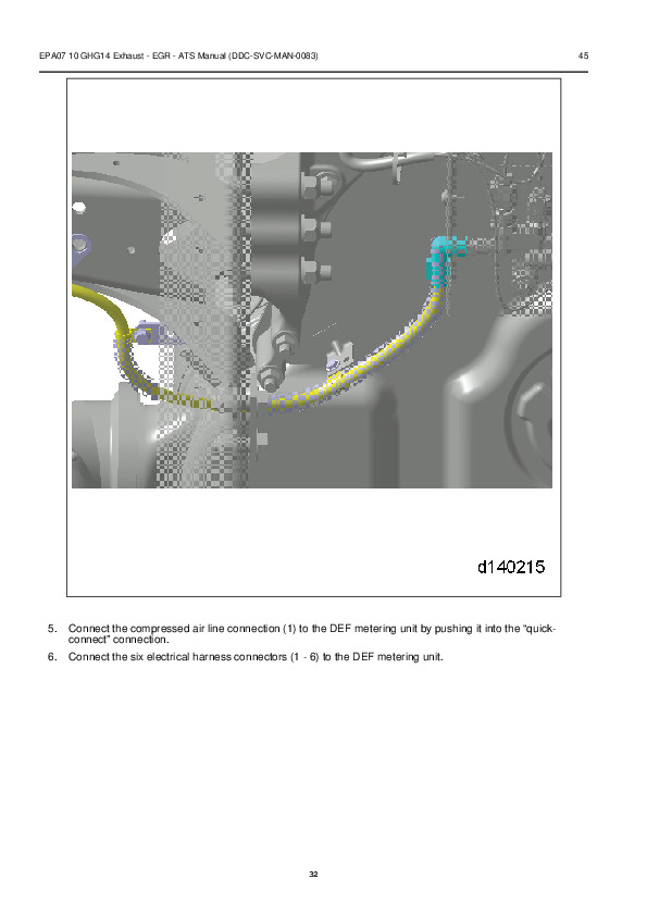
Language: English
Electrical Wiring Diagrams
Electrical Wiring Diagrams/DD Platform EPA07 (DDECVI) EPA10 (DDEC10) GHG14 (DDEC13)
Electrical Wiring Diagrams/DD Platform EPA07 (DDECVI) EPA10 (DDEC10) GHG14 (DDEC13).pdf
Electrical Wiring Diagrams/Detroit™ Transmissions TCM Wiring Harness.png
Electrical Wiring Diagrams/Detroit Transmissions TCM Wiring Harness.png
Electrical Wiring Diagrams/Electrical wiring schematisc.JPG
Electrical Wiring Diagrams/EPA07 DD13 Motor Control Module (MCM) Engine Harness.pdf
Electrical Wiring Diagrams/EPA10 14-Pin Connectors.pdf
Electrical Wiring Diagrams/EPA10 Aftertreatment 1-BOX™ Wiring Schematic.pdf
Electrical Wiring Diagrams/EPA10 Aftertreatment 2HH Pierce Wiring Schematic.pdf
Electrical Wiring Diagrams/EPA10 Aftertreatment 2HV Two-Box Wiring Schematic.pdf
Electrical Wiring Diagrams/EPA10 Aftertreatment 2V2 Two-Box Wiring Schematic.pdf
Electrical Wiring Diagrams/EPA10 Aftertreatment Control Module (ACM2) Electrical Schematic.pdf
Electrical Wiring Diagrams/EPA10 Common Powertrain Controller (CPC2+) Vehicle Interface Harness (VIH).pdf
Electrical Wiring Diagrams/EPA10 DD13 Motor Control Module (MCM2) Engine Harness (page 1).pdf
Electrical Wiring Diagrams/EPA10 DD13 Motor Control Module (MCM2) Engine Harness (page 2).pdf
Electrical Wiring Diagrams/EPA10 DD15 Motor Control Module (MCM2) Engine Harness (page 1).pdf
Electrical Wiring Diagrams/EPA10 DD15 Motor Control Module (MCM2) Engine Harness (page 2).pdf
Electrical Wiring Diagrams/EuroIV Common Powertrain Controller (CPC2) Vehicle Interface Harness (VIH).pdf
Electrical Wiring Diagrams/EuroIV Export DD15 Motor Control Module (MCM) Engine Harness (page 1).pdf
Electrical Wiring Diagrams/EuroIV Export DD15 Motor Control Module (MCM) Engine Harness (page 2).pdf
Electrical Wiring Diagrams/GHG14 Aftertreatment Control Module (ACM2.1) Electrical Schematic.pdf
Electrical Wiring Diagrams/GHG14 Common Powertrain Controller (CPC4) Vehicle Interface Harness (VIH).pdf
Electrical Wiring Diagrams/GHG14 DD13 Motor Control Module (MCM2.1) Engine Harness (page 1).pdf
Electrical Wiring Diagrams/GHG14 DD13 Motor Control Module (MCM2.1) Engine Harness (page 2).pdf
Electrical Wiring Diagrams/GHG14 DD15 and DD16 Motor Control Module (MCM2.1) Engine Harness (page 1).pdf
Electrical Wiring Diagrams/GHG14 DD15 and DD16 Motor Control Module (MCM2.1) Engine Harness (page 2).pdf
Electrical Wiring Diagrams/Horizontal ATD wiring – OEM and DDC Responsibility.pdf
Electrical Wiring Diagrams/MBE 900 (EPA04) DDEC-ECU EGR Engine Harness and Vehicle Interface Harness (page 1).pdf
Electrical Wiring Diagrams/MBE 900 (EPA04) DDEC-ECU EGR Engine Harness and Vehicle Interface Harness (page 2).pdf
Electrical Wiring Diagrams/MBE 900 (EPA07) Engine Harness (MCM-CPC) and Vehicle Interface Harness (page 1).pdf
Electrical Wiring Diagrams/MBE 900 (EPA07) Engine Harness (MCM-CPC) and Vehicle Interface Harness (page 2).pdf
Electrical Wiring Diagrams/MBE 4000 (EPA04) DDEC-ECU EGR Engine Harness and Vehicle Interface Harness (page 1).pdf
Electrical Wiring Diagrams/MBE 4000 (EPA04) DDEC-ECU EGR Engine Harness and Vehicle Interface Harness (page 2).pdf
Electrical Wiring Diagrams/MBE 4000 (EPA07) Engine Harness (MCM-CPC) and Vehicle Interface Harness (page 1).pdf
Electrical Wiring Diagrams/MBE 4000 (EPA07) Engine Harness (MCM-CPC) and Vehicle Interface Harness (page 2).pdf
Electrical Wiring Diagrams/MBE Platform Electronic Wiring Schematics.pdf
Electrical Wiring Diagrams/Series 50, 50G & 60 Electronic Wiring Schematics.pdf
Electrical Wiring Diagrams/Series 50 DDEC IV My2003 EGR Engine Sensor Harness and Vehicle Interface Harness (page 1).pdf
Electrical Wiring Diagrams/Series 50 DDEC IV My2003 EGR Engine Sensor Harness and Vehicle Interface Harness (page 2).pdf
Electrical Wiring Diagrams/Series 50G DDEC IV My2003 EGR Engine Sensor Harness and Vehicle Interface Harness (page 1).pdf
Electrical Wiring Diagrams/Series 50G DDEC IV My2003 EGR Engine Sensor Harness and Vehicle Interface Harness (page 2).pdf
Electrical Wiring Diagrams/Series 60 DDEC III-IV Engine Harness and Vehicle Interface Harness (page 1).pdf
Electrical Wiring Diagrams/Series 60 DDEC III-IV Engine Harness and Vehicle Interface Harness (page 2).pdf
Electrical Wiring Diagrams/Series 60 DDEC IV My2003 EGR Engine Sensor Harness and Vehicle Interface Harness (page 1).pdf
Electrical Wiring Diagrams/Series 60 DDEC IV My2003 EGR Engine Sensor Harness and Vehicle Interface Harness (page 2).pdf
Electrical Wiring Diagrams/Series 60 DDEC V EGR Engine Harness and Vehicle Interface Harness (page 1).pdf
Electrical Wiring Diagrams/Series 60 DDEC V EGR Engine Harness and Vehicle Interface Harness (page 2).pdf
Electrical Wiring Diagrams/Series 60 DDEC V Engine Harness and Vehicle Interface Harness (Non-Road Equipment) page 1.pdf
Electrical Wiring Diagrams/Series 60 DDEC V Engine Harness and Vehicle Interface Harness (Non-Road Equipment) page 2.pdf
Electrical Wiring Diagrams/Series 60 (EPA07) DDEC VI MCM-CPC EGR Engine Harness and Vehicle Interface Harness (page 1).pdf
Electrical Wiring Diagrams/Series 60 (EPA07) DDEC VI MCM-CPC EGR Engine Harness and Vehicle Interface Harness (page 2).pdf
Electrical Wiring Diagrams/Vertical ATD wiring – OEM and DDC Responsibility.pdf
Others/DDEC6_X_2007-2012_epa07_10
Others/2-Box Diesel Oxidation Catalyst – Diesel Particulate Filter.pdf
Others/2-Box Selective Catalytic Reduction (SCR Catalyst).pdf
Others/2HH Soot Sensor.pdf
Others/2V2 GHG14 Selective Catalytic Reduction NOx Sensor.pdf
Others/7SE500 0409 – UNIT FUEL INJECTORS AND UNIT PUMP TECHNICIAN GUIDE.pdf
Others/61527967-Ajuste-Valvulas-e-Inyectores-Detroit.pdf
Others/289329134-Detroit-DD15-Valve-Adjustment.pdf
Others/Aftertreatment Device Electronics.pdf
Others/Aftertreatment System Overview.pdf
Others/Allison Transmission – AT540 AT1542 Service Manual.pdf
Others/DD13 Exhaust Flanged Manifold.pdf
Others/DD13 Exhaust Gas Recirculation Cooler Water Manifold Assembly.pdf
Others/DD13 Exhaust Gas Recirculation Valve.pdf
Others/DD13 Exhaust Gas Recirculation Valve Actuator.pdf
Others/DD13 Exhaust Gas Recirculation Valve Actuator Pull Rod.pdf
Others/DD15 and DD16 Exhaust Gas Recirculation Cooler.pdf
Others/DD15 and DD16 Exhaust Gas Recirculation Valve.pdf
Others/DD15 and DD16 Exhaust Gas Recirculation Valve Actuator.pdf
Others/DD15 and DD16 Exhaust Gas Recirculation Valve Actuator Pull Rod.pdf
Others/DD15 and DD16 Exhaust S-pipe (Elbow).pdf
Others/DDC-SVC-MAN-0073 – DD PLATFORM APPLICATION AND INSTALLATION MANUAL.pdf
Others/DDC-SVC-MAN-0081 2010 – EPA07_10 DD PLATFORM WORKSHOP MANUAL – ENGINE.pdf
Others/DDC-SVC-MAN-0110 – DDEC IV APPLICATION AND INSTALLATION MANUAL.pdf
Others/DDECIV_EGRddc-svc-man-0109.pdf
Others/DDECVddc-svc-man-0108.pdf
Others/DD_EuroIV_DDECVIddc-svc-man-0185.pdf
Others/Detroit_dd13.pdf
Others/Detroit Diesel – Cooling System – Technicians Guide.pdf
Others/Detroit Diesel – DDEC II to III-IV Conversion .pdf
Others/Detroit Diesel – DDEC VI – Application And Installation Manual.pdf
Others/Detroit Diesel – DDEC VI SERIES 60 MCM EGR Engine Harness Schematic.pdf
Others/Detroit Diesel – Fuel System Bulletin – MBE 4000-06a.pdf
Others/Detroit Diesel – Low Power Bulletin – MBE4000-07.pdf
Others/Detroit Diesel – MBE 4000 Application And Installation ch13.pdf
Others/Detroit Diesel – MBE 4000 ENGINE EPA04 OPERATOR’S MANUAL – DDC-SVC-MAN-0056.pdf
Others/Detroit Diesel – Series 50G – 60G Training Program.ppt
Others/Det_Trans_ddc-svc-man-0128.pdf
Others/Diesel Exhaust Fluid and Coolant Lines.pdf
Others/Diesel Exhaust Fluid Tank.pdf
Others/Diesel Exhaust Fluid Tank Header Unit.pdf
Others/Diesel Oxidation Catalyst Inlet Pressure Sensor.pdf
Others/EPA07 10 GHG14 Exhaust – EGR – ATS Manual (DDC-SVC-MAN-0083)_.pdf
Others/EPA07 Aftertreatment Device Cleaning and Maintenance.pdf
Others/EPA07 Aftertreatment Device Removal and Installation on Vehicle.pdf
Others/EPA07 Aftertreatment Device Sensors.pdf
Others/EPA07 Aftertreatment System Overview.pdf
Others/EPA07_DDECVIddc-svc-man-0054.pdf
Others/EPA10 1-BOX from the Vehicle.pdf
Others/EPA10 1-BOX Sensor Box.pdf
Others/EPA10 2-BOX from the Vehicle.pdf
Others/EPA10_DDEC10ddc-svc-man-0045.pdf
Others/EPA10 Diesel Exhaust Fluid Metering Unit.pdf
Others/EPA10 Diesel Exhaust Fluid Nozzle.pdf
Others/EPA10 Diesel Exhaust Fluid Pump Module and Components.pdf
Others/EPA10 Diesel Particulate Filter.pdf
Others/Exhaust Gas Recirculation Actuator Lever.pdf
Others/Exhaust Gas Recirculation Crossover Tube.pdf
Others/Exhaust Gas Recirculation Hot Pipe.pdf
Others/Exhaust Gas Recirculation System – Cleaning.pdf
Others/Exhaust Gas Recirculation Venturi.pdf
Others/Fuel Compensation Pressure Sensor.pdf
Others/Fuel Doser Injector Valve.pdf
Others/GHG14 1-BOX from the Vehicle.pdf
Others/GHG14 2-BOX (2V2) From the Vehicle.pdf
Others/GHG14 2-BOX From the Vehicle.pdf
Others/GHG14 DD15 AT Exhaust Gas Recirculation Actuator Pull Rod.pdf
Others/GHG14 DD15 AT Exhaust Gas Recirculation Valve.pdf
Others/GHG14 DD15 AT Exhaust Gas Recirculation Valve Actuator.pdf
Others/GHG14 DD15 AT Flanged Exhaust Manifold.pdf
Others/GHG14_DDEC13ddc-svc-man-0127.pdf
Others/GHG14 Diesel Exhaust Fluid Dosing System.pdf
Others/GHG14 Diesel Exhaust Fluid Lines.pdf
Others/Grid Heater (EPA07).pdf
Others/Hydrocarbon Doser Block.pdf
Others/Hydrocarbon Doser Block Feed Line.pdf
Others/Hydrocarbon Doser Coolant Lines.pdf
Others/Hydrocarbon Fuel Doser Housing.pdf
Others/Intake Throttle Valve and Adaptor.pdf
Others/Mixer Pipe.pdf
Others/Resetting Diesel Particulate Filter Ash Accumulators.pdf
Others/SCR.pdf
Others/DDEC6_X_2007-2012_epa07_10/epa7 10 faults.pdf
Others/DDEC6_X_2007-2012_epa07_10/in_ex_turbo.pdf
Others/DDEC6_X_2007-2012_epa07_10/lube.pdf
Others/DDEC6_X_2007-2012_epa07_10/mechanical.pdf
Others/DDEC6_X_2007-2012_epa07_10/V4_PV776_370_98198_1_EngineECU_CumminsISX_VN_B9_98.pdf
Electrical Wiring Diagrams…..2
DD Platform EPA07 (DDECVI) EPA10 (DDEC10) GHG14 (DDEC13)…..4
EPA07 DD13 Motor Control Module (MCM) Engine Harness (page 1)…..5
EPA07 DD13 Motor Control Module (MCM) Engine Harness (page 2)…..6
EPA07 DD15 Motor Control Module (MCM) Engine Harness (page 1)…..7
EPA07 DD15 Motor Control Module (MCM) Engine Harness (page 2)…..8
EPA10 14-Pin Connectors…..9
EPA10 Aftertreatment 1-BOX™ Wiring Schematic…..10
EPA10 Aftertreatment 2HH Pierce Wiring Schematic…..11
EPA10 Aftertreatment 2HV Two-Box Wiring Schematic…..12
EPA10 Aftertreatment 2V2 Two-Box Wiring Schematic…..13
EPA10 Aftertreatment Control Module (ACM2) Electrical Schematic…..14
EPA10 Common Powertrain Controller (CPC2+) Vehicle Interface Harness (VIH)…..15
EPA10 DD13 Motor Control Module (MCM2) Engine Harness (page 1)…..16
EPA10 DD13 Motor Control Module (MCM2) Engine Harness (page 2)…..17
EPA10 DD15 Motor Control Module (MCM2) Engine Harness (page 1)…..18
EPA10 DD15 Motor Control Module (MCM2) Engine Harness (page 2)…..19
EuroIV Common Powertrain Controller (CPC2) Vehicle Interface Harness (VIH)…..20
EuroIV Export DD15 Motor Control Module (MCM) Engine Harness (page 1)…..21
EuroIV Export DD15 Motor Control Module (MCM) Engine Harness (page 2)…..22
GHG14 Aftertreatment Control Module (ACM2.1) Electrical Schematic…..23
GHG14 Common Powertrain Controller (CPC4) Vehicle Interface Harness (VIH)…..24
GHG14 DD13 Motor Control Module (MCM2.1) Engine Harness (page 1)…..25
GHG14 DD13 Motor Control Module (MCM2.1) Engine Harness (page 2)…..26
GHG14 DD15 and DD16 Motor Control Module (MCM2.1) Engine Harness (page 1)…..27
GHG14 DD15 and DD16 Motor Control Module (MCM2.1) Engine Harness (page 2)…..28
Horizontal ATD wiring – OEM and DDC Responsibility…..29
MBE 4000 (EPA04) DDEC-ECU EGR Engine Harness and Vehicle Interface Harness (page 1)…..30
MBE 4000 (EPA04) DDEC-ECU EGR Engine Harness and Vehicle Interface Harness (page 2)…..31
MBE 4000 (EPA07) Engine Harness (MCM-CPC) and Vehicle Interface Harness (page 1)…..32
MBE 4000 (EPA07) Engine Harness (MCM-CPC) and Vehicle Interface Harness (page 2)…..33
MBE 900 (EPA04) DDEC-ECU EGR Engine Harness and Vehicle Interface Harness (page 1)…..34
MBE 900 (EPA04) DDEC-ECU EGR Engine Harness and Vehicle Interface Harness (page 2)…..35
MBE 900 (EPA07) Engine Harness (MCM-CPC) and Vehicle Interface Harness (page 1)…..36
MBE 900 (EPA07) Engine Harness (MCM-CPC) and Vehicle Interface Harness (page 2)…..37
MBE Platform Electronic Wiring Schematics…..38
Series 50 DDEC IV My2003 EGR Engine Sensor Harness and Vehicle Interface Harness (page 1)…..39
Series 50 DDEC IV My2003 EGR Engine Sensor Harness and Vehicle Interface Harness (page 2)…..40
Series 50, 50G & 60 Electronic Wiring Schematics…..41
Series 50G DDEC IV My2003 EGR Engine Sensor Harness and Vehicle Interface Harness (page 1)…..42
Series 50G DDEC IV My2003 EGR Engine Sensor Harness and Vehicle Interface Harness (page 2)…..43
Series 60 (EPA07) DDEC VI MCM-CPC EGR Engine Harness and Vehicle Interface Harness (page 1)…..44
Series 60 (EPA07) DDEC VI MCM-CPC EGR Engine Harness and Vehicle Interface Harness (page 2)…..45
Series 60 DDEC III-IV Engine Harness and Vehicle Interface Harness (page 1)…..46
Series 60 DDEC III-IV Engine Harness and Vehicle Interface Harness (page 2)…..47
Series 60 DDEC IV My2003 EGR Engine Sensor Harness and Vehicle Interface Harness (page 1)…..48
Series 60 DDEC IV My2003 EGR Engine Sensor Harness and Vehicle Interface Harness (page 2)…..49
Series 60 DDEC V EGR Engine Harness and Vehicle Interface Harness (page 1)…..50
Series 60 DDEC V EGR Engine Harness and Vehicle Interface Harness (page 2)…..51
Series 60 DDEC V Engine Harness and Vehicle Interface Harness (Non-Road Equipment) page 1…..52
Series 60 DDEC V Engine Harness and Vehicle Interface Harness (Non-Road Equipment) page 2…..53
Vertical ATD wiring – OEM and DDC Responsibility…..54
Others…..55
2-Box Diesel Oxidation Catalyst – Diesel Particulate Filter…..59
59.1 Diesel Oxidation Catalyst – Diesel Particulate Filter Additional Removal Information…..59
59.2 Removal of the 2–Box Diesel Oxidation Catalyst / Diesel Particulate Filter…..60
59.3 Installation of the 2–Box Diesel Oxidation Catalyst / Diesel Particulate Filter…..61
59.4 Removal of the GHG14 Two-Box Diesel Oxidation Catalyst…..63
59.5 Installation of the GHG14 Two-Box Diesel Oxidation Catalyst…..64
59.6 Removal of the 2-Box Diesel Particulate Filter…..65
59.7 Installation of the 2-Box Diesel Particulate Filter…..66
2-Box Diesel Oxidation Catalyst – Diesel Particulate Filter…..67
59.1 Diesel Oxidation Catalyst – Diesel Particulate Filter Additional Removal Information…..67
59.2 Removal of the 2–Box Diesel Oxidation Catalyst / Diesel Particulate Filter…..68
59.3 Installation of the 2–Box Diesel Oxidation Catalyst / Diesel Particulate Filter…..69
59.4 Removal of the GHG14 Two-Box Diesel Oxidation Catalyst…..71
59.5 Installation of the GHG14 Two-Box Diesel Oxidation Catalyst…..72
59.6 Removal of the 2-Box Diesel Particulate Filter…..73
59.7 Installation of the 2-Box Diesel Particulate Filter…..74
2-Box Selective Catalytic Reduction (SCR Catalyst)…..75
60.1 Selective Catalytic Reduction (SCR Catalyst) Additional Removal Information…..75
60.2 Removal of the Selective Catalytic Reduction (SCR Catalyst) from the Stanchion…..76
60.3 Installation of the Selective Catalytic Reduction (SCR) Catalyst to the Stanchion…..77
60.4 Removal of the Selective Catalytic Reduction (SCR Catalyst)…..79
60.5 Installation of the Selective Catalytic Reduction (SCR Catalyst)…..80
2-Box Selective Catalytic Reduction (SCR Catalyst)…..81
60.1 Selective Catalytic Reduction (SCR Catalyst) Additional Removal Information…..81
60.2 Removal of the Selective Catalytic Reduction (SCR Catalyst) from the Stanchion…..82
60.3 Installation of the Selective Catalytic Reduction (SCR) Catalyst to the Stanchion…..83
60.4 Removal of the Selective Catalytic Reduction (SCR Catalyst)…..85
60.5 Installation of the Selective Catalytic Reduction (SCR Catalyst)…..86
289329134-Detroit-DD15-Valve-Adjustment…..87
2HH Soot Sensor…..90
62.1 Removal of the 2V2/2HH Soot Sensor…..90
62.2 Installation of the 2V2/2HH Soot Sensor…..93
2V2/2HH Soot Sensor…..95
62.1 Removal of the 2V2/2HH Soot Sensor…..95
62.2 Installation of the 2V2/2HH Soot Sensor…..98
2V2 GHG14 Selective Catalytic Reduction NOx Sensor…..100
61.1 Removal of the 2V2 GHG14 Selective Catalytic Reduction NOx Sensor…..100
61.2 Installation of the 2V2 GHG14 Selective Catalytic Reduction NOx Sensor…..102
2V2 GHG14 Selective Catalytic Reduction NOx Sensor…..104
61.1 Removal of the 2V2 GHG14 Selective Catalytic Reduction NOx Sensor…..104
61.2 Installation of the 2V2 GHG14 Selective Catalytic Reduction NOx Sensor…..106
61527967-Ajuste-Valvulas-e-Inyectores-Detroit…..108
toc…..108
INTRODUCTION…..108
DETAILS AND REASON…..108
Disconnect starting power for engine…..108
Remove the engine valve rocker cover as outlined. Refer to secti…..108
Insert a 3/4 in. drive breaker bar or ratchet into the square ho…..108
Bar the engine in the direction of rotation and observe a cylind…..108
Stop turning the engine and mount a magnetic base dial indicator…..108
Set the pedestal of the dial indicator on the top of the injecto…..108
Continue to slowly bar the engine over in the direction of rotat…..108
This is the point of maximum injector roller lift, the injector …..108
If you rotate the engine beyond this point you will have to bar …..108
Stop engine rotation and note which cylinder this is, and follow…..109
This injector can now be set using this procedure:…..109
Loosen the locknut on the adjusting screw at least two full turn…..109
Tighten the adjusting screw until the injector plunger bottoms o…..109
Back the adjusting screw off 3/4 of a turn 0.75 mm 0.25 mm and…..109
The injector is now adjusted…..109
Adjust the valves on the corresponding cylinders listed in Table…..109
To adjust the intake valves, insert a 0.203 mm (0.008 in.) feele…..110
Loosen the locknut, and turn the adjusting set screw until the f…..110
Torque the locknut to 41 – 47 N m (30 – 35 lb ft) and remove the…..110
The exhaust valves are adjusted the same way as the intake valve…..111
Repeat steps 4 thru 11 until all injectors and valves have been …..111
Install the engine rocker cover. Refer to section 1.6.8 for one-…..111
Reconnect starting power to the engine…..111
7SE500 0409 – UNIT FUEL INJECTORS AND UNIT PUMP TECHNICIAN GUIDE…..114
Aftertreatment Device Electronics…..190
38.1 Description and Operation of the Aftertreatment Control Module…..190
38.2 EPA10/GHG14 Aftertreatment Device Sensor Locations…..191
1-BOX™ Sensor Locations…..191
Diesel Oxidation Catalyst, Diesel Particulate Filter, and Selective Catalytic Reduction (SCR Catalyst) Mounted Vertically…..193
Diesel Oxidation Catalyst, Diesel Particulate Filter Mounted Horizontally, Selective Catalytic Reduction (SCR Catalyst) Mounted Vertically…..195
38.3 Removal of the Aftertreatment Control Module…..198
38.4 Installation of the Aftertreatment Control Module…..199
EPA10/GHG14 Aftertreatment Device Electronics…..200
38.1 Description and Operation of the Aftertreatment Control Module…..200
38.2 EPA10/GHG14 Aftertreatment Device Sensor Locations…..201
1-BOX™ Sensor Locations…..201
Diesel Oxidation Catalyst, Diesel Particulate Filter, and Selective Catalytic Reduction (SCR Catalyst) Mounted Vertically…..203
Diesel Oxidation Catalyst, Diesel Particulate Filter Mounted Horizontally, Selective Catalytic Reduction (SCR Catalyst) Mounted Vertically…..205
38.3 Removal of the Aftertreatment Control Module…..208
38.4 Installation of the Aftertreatment Control Module…..209
Aftertreatment System Overview…..210
37.1 Description and Operation of the EPA10 Aftertreatment System…..210
1-BOX™ Aftertreatment System Configuration…..210
2-Box Aftertreatment Systems Configurations…..210
Diesel Oxidation Catalyst, Diesel Particulate Filter, and Selective Catalytic Reduction Mounted Vertically…..210
Diesel Oxidation Catalyst, Diesel Particulate Filter Mounted Horizontally, Selective Catalytic Reduction Mounted Vertically…..211
Diesel Oxidation Catalyst (DOC), Diesel Particulate Filter (DPF), Selective Catalytic Reduction (SCR Catalyst) Mounted Horizontal…..212
37.2 Description and Operation of the Diesel Particulate Filter…..214
37.3 Description and Operation of the Selective Catalytic Reduction (SCR Catalyst)…..215
37.4 Description and Operation of the EPA10 Diesel Exhaust Fluid Heating…..216
37.5 Description and Operation of the GHG14 Diesel Exhaust Fluid Heating…..217
37.6 Description and Operation of the Diesel Exhaust Fluid Flow…..218
37.7 Description and Operation of the Diesel Exhaust Fluid (Compressed Air Flow)…..219
37.8 EPA10/GHG14 Aftertreatment Regeneration Strategy…..220
EPA10/GHG14 Zone Trigger…..220
EPA10/GHG14 Regeneration Strategy…..220
Passive Regeneration…..221
Active Regeneration…..221
Parked Regeneration…..222
37.9 Performing a Parked Regeneration – EPA10/GHG14…..224
37.10 Performing a Parked Regeneration Using DiagnosticLink®…..226
37.11 EPA10/GHG14 Aftertreatment Diesel Exhaust Fluid Gauge/Lamps…..227
37.12 Instrument Panel Lamps…..228
Amber Warning Lamp…..228
Red Stop Lamp…..228
Diesel Particulate Filter Regeneration Lamp…..228
High Exhaust System Temperature Lamp…..229
Malfunction Indicator Lamp…..229
Fuel Filter Restriction Sensor Lamp: Fuel Filter Failed…..229
Water-In-Fuel Lamp (WIF)…..230
EPA10/GHG14 Aftertreatment System Overview…..231
37.1 Description and Operation of the EPA10 Aftertreatment System…..231
1-BOX™ Aftertreatment System Configuration…..231
2-Box Aftertreatment Systems Configurations…..231
Diesel Oxidation Catalyst, Diesel Particulate Filter, and Selective Catalytic Reduction Mounted Vertically…..231
Diesel Oxidation Catalyst, Diesel Particulate Filter Mounted Horizontally, Selective Catalytic Reduction Mounted Vertically…..232
Diesel Oxidation Catalyst (DOC), Diesel Particulate Filter (DPF), Selective Catalytic Reduction (SCR Catalyst) Mounted Horizontal…..233
37.2 Description and Operation of the Diesel Particulate Filter…..235
37.3 Description and Operation of the Selective Catalytic Reduction (SCR Catalyst)…..236
37.4 Description and Operation of the EPA10 Diesel Exhaust Fluid Heating…..237
37.5 Description and Operation of the GHG14 Diesel Exhaust Fluid Heating…..238
37.6 Description and Operation of the Diesel Exhaust Fluid Flow…..239
37.7 Description and Operation of the Diesel Exhaust Fluid (Compressed Air Flow)…..240
37.8 EPA10/GHG14 Aftertreatment Regeneration Strategy…..241
EPA10/GHG14 Zone Trigger…..241
EPA10/GHG14 Regeneration Strategy…..241
Passive Regeneration…..242
Active Regeneration…..242
Parked Regeneration…..243
37.9 Performing a Parked Regeneration – EPA10/GHG14…..245
37.10 Performing a Parked Regeneration Using DiagnosticLink®…..247
37.11 EPA10/GHG14 Aftertreatment Diesel Exhaust Fluid Gauge/Lamps…..248
37.12 Instrument Panel Lamps…..249
Amber Warning Lamp…..249
Red Stop Lamp…..249
Diesel Particulate Filter Regeneration Lamp…..249
High Exhaust System Temperature Lamp…..250
Malfunction Indicator Lamp…..250
Fuel Filter Restriction Sensor Lamp: Fuel Filter Failed…..250
Water-In-Fuel Lamp (WIF)…..251
Allison Transmission – AT540 AT1542 Service Manual…..252
SM1241-9602-TOC.pdf…..0
Section 1. GENERAL INFORMATION…..256
Section 2. DESCRIPTION AND OPERATION…..256
Section 3. PREVENTIVE MAINTENANCE…..257
Section 4. GENERAL OVERHAUL INFORMATION…..258
Section 5. DISASSEMBLY OF TRANSMISSION…..258
Section 6. REBUILD OF SUBASSEMBLIES…..259
Section 7. ASSEMBLY OF TRANSMISSION…..260
Section 8. WEAR LIMITS AND SPRING DATA…..260
Section 9. CUSTOMER SERVICE…..260
CROSS-SECTION VIEWS…..261
SCHEMATIC VIEW…..261
EXPLODED VIEWS…..261
SM1241-9602-01.pdf…..0
1–1. SCOPE OF MANUAL…..262
a. Coverage…..262
b. Illustrations. Overhaul procedures are illustrated mainly by photographs. Line drawings are us……262
c. Maintenance Information. Each task outlined in this Service Manual has been successfully accom……262
1–2. SUPPLEMENTARY INFORMATION…..262
1–3. ORDERING PARTS…..262
a. Transmission Nameplate. The nameplate (Figure 1–5) is located on the right-rear side of the tr……262
b. Parts Catalog. Do not order by illustration item numbers on exploded views in this manual. All……262
Figure 1–1. AT 1545 Automatic Transmission — Left-Front View…..263
Figure1–2. AT 545R Automatic Transmission — Right-Rear View…..263
Figure1–3. AT 543 Automatic Transmission — Left-Front View…..264
Figure1–4. AT 542, 543, 1542 Automatic Transmission — Right-Rear View…..264
Figure1–5. Transmission Nameplate…..265
1–4. GENERAL DESCRIPTION…..265
a. Automatic, Four Speeds. The AT 500 and 1500 Series transmissions have four forward speeds and ……265
b. Torque Converter and Lockup Clutch. An Allison three-element torque converter (Foldout 1, 2, o……265
c. Planetary Gearing, Clutches. Ratios for four forward speeds and reverse are established by pla……265
d. Main Control Valve Body. The main control valve body consists of a series of spring-loaded spo……265
1–5. OPERATING INSTRUCTIONS…..265
1–6. SPECIFICATIONS AND DATA…..265
Table 1–1. Specifications and Data (cont’d)…..265
Table 1–1. Specifications and Data (cont’d)…..268
SM1241-9602-02.pdf…..0
2–1. SCOPE…..270
2–2. MOUNTING…..270
a. To Engine. The front of the transmission housing is an SAE size 3 flange. This flange is bolte……270
b. To Vehicle. Two 5⁄8-11 tapped holes at each side of the transmission are provided for mounting……270
2–3. INPUT DRIVE…..270
a. For models other than AT 543, six tapped lugs are on the front of torque converter 1 (Foldout ……270
b. For AT 543 models, six threaded studs are on the front of torque converter 2 (Foldout 7,A) for……270
2–4. TRANSMISSION HOUSING…..270
2–5. TORQUE CONVERTER ASSEMBLY AND LOCKUP CLUTCH…..270
a. Description…..270
b. Operation (Foldout 1, 2, or 3)…..270
2–6. OIL PUMP ASSEMBLY…..271
a. Description (Foldout 7,B)…..271
b. Operation (Foldout 7,B)…..271
2–7. FORWARD CLUTCH AND TURBINE SHAFT…..271
a. Description (Foldout 8)…..271
b. Operation (Foldout 8)…..271
2–8. FOURTH CLUTCH…..272
a. Description (Foldout 9,A)…..272
b. Operation (Foldout 9,A)…..272
2–9. SECOND AND THIRD CLUTCH AND CENTER SUPPORT…..272
a. Description (Foldout 9,B)…..272
b. Operation of Third Clutch (Foldout 9,B)…..272
c. Operation of Second Clutch (Foldout 9,B)…..273
2–10. FIRST CLUTCH…..273
a. Description (Foldout 10,B)…..273
b. Operation (Foldout 10,B)…..273
2–11. PLANETARY GEAR UNIT…..273
a. Description (Foldout 10,A)…..273
b. Operation. Refer to Paragraph 2–19…..273
2–12. SPEEDOMETER DRIVE/SPEED SENSOR WHEEL…..274
a. Description (Foldout 12,B)…..274
b. Operation (Foldout 12,B)…..274
2–13. GOVERNOR…..274
a. Description (Foldout 12,A). Governor assembly 19 is a centrifugal (flyweight) governor, driven……274
b. Operation (Foldout 12,A). When the governor rotates, centrifugal force causes weights to move ……274
2–14. MODULATOR…..274
a. Vacuum Modulator (Foldout 12,A)…..274
b. Mechanical Modulator…..274
c. Electric Modulator…..274
2–15. OIL PAN AND FILTER…..275
a. Description (Foldout 12,B)…..275
b. Function (Foldout 12,B)…..275
2–16. HYDRAULIC RETARDER…..275
a. Description…..275
b. Operation…..275
2–17. MAIN CONTROL VALVE ASSEMBLY…..276
2–18. HYDRAULIC SYSTEM…..276
a. System Functions. The hydraulic system generates, directs, and controls the pressure and flow ……276
b. System Schematic (Foldout 5 or 6). Color- coded foldouts of the hydraulic systems are presente……276
c. Filter, Pump Circuit. Transmission fluid is drawn from the sump through a filter screen by the……276
d. Main-Pressure Circuit (Red)…..276
e. Converter-In (Yellow), Converter-Out (Orange), Lubrication (Green) Circuits…..277
f. Selector Valve, Neutral, Forward Regulator Circuit (Orange and Yellow)…..277
g. Governor Valve, Governor Circuit (Green and White)…..277
h. Modulator Pressure Circuit (Red and Green)…..277
i. Clutch Circuits…..278
j. Hold Regulator Valve…..278
k. Automatic Upshifts…..278
l. Automatic Downshifts…..278
m. Downshift Inhibiting…..278
n. Trimmer Valves…..279
o. Priority Valve…..279
p. Trimmer Regulator Valve…..279
Figure 2–1. Neutral Power Flow…..280
2–19. TORQUE PATHS THROUGH TRANSMISSION…..280
a. Converter Operation. Power is transmitted hydraulically through the torque converter. The engi……280
b. Neutral Operation (Figure 2–1)…..280
Figure2–2. First Range Power Flow…..281
c. First-Range Operation (Figure 2–2)…..281
Figure2–3. Second Range Power Flow…..282
d. Second-Range Operation (Figure 2–3)…..282
Figure2–4. Third Range Power Flow…..283
e. Third-Range Operation (Figure 2–4). The forward and the third clutches are applied. The third ……283
f. Converter Operation (AT 1500 Series Models). During converter operation, 3–4 clutch feed press……283
g. Lockup Operation (AT 1500 Series Models). After the 2–3 upshift has occurred, main pressure be……283
Figure2–5. Fourth Range Power Flow…..284
h. Fourth-Range Operation (Figure 2–5). The forward and fourth clutches are applied. With the clu……284
i. Fourth-Range Lockup Operation (AT 1500 Series Models). Except for a momentary shift to convert……284
Figure2–6. Reverse Power Flow…..285
j. Reverse Operation (Figure 2–6). Reverse is the only range in which the forward clutch is not e……285
SM1241-9602-03.pdf…..0
3–1. SCOPE…..286
3–2. PERIODIC INSPECTION AND CARE…..286
a. Clean and inspect the exterior of the transmission at regular intervals. The severity of servi……286
b. Check the transmission hydraulic level at the intervals specified in the vehicle operator manual…..286
3–3. IMPORTANCE OF PROPER TRANSMISSION FLUID LEVEL…..286
a. Effects of Improper Fluid Level. Because the transmission fluid cools, lubricates, and transmi……286
b. Foaming and Aerating…..286
3–4. DIPSTICK MARKINGS…..286
Figure 3–1. Dipstick With FULL and ADD Markings…..287
Figure3–2. Dipstick With HOT RUN Markings…..287
Figure3–3. Dipstick With HOT OVERFULL Markings…..287
3–5. TRANSMISSION FLUID LEVEL CHECK PROCEDURE…..287
a. Preparation…..287
b. Cold Check…..288
c. Hot Check…..288
3–6. KEEPING TRANSMISSION FLUID CLEAN…..288
3–7. TRANSMISSION FLUID RECOMMENDATIONS…..288
Table 3–1. Operating Temperature Requirements for Transmission Fluid…..289
3–8. TRANSMISSION FLUID AND FILTER CHANGE INTERVALS…..289
3–9. TRANSMISSION FLUID CONTAMINATION…..289
a. Examine at Fluid Change. At each fluid change, examine the fluid which is drained for evidence……289
b. Metal Particles. Metal particles in the fluid (except for the minute particles normally trappe……289
c. Coolant Leakage. If engine coolant leaks into the transmission hydraulic system, immediate act……289
d. Auxiliary Filter (Figure 3–4)…..289
Table 3–2. Transmission Fluid and Filter Change Intervals …..290
Table 3–3. Fluid Oxidation Measurement Limits…..290
Figure3–4. Installation of Auxiliary Filter (Models Without Retarder)…..291
3–10. TRANSMISSION FLUID AND FILTER CHANGE PROCEDURES…..292
a. Disassembly (Foldout 12,B)…..292
b. Assembly (Foldout 12,B)…..292
3–11. BREATHER…..293
Figure3–5. Measuring the Length of Oil Pan Boss to Identify Torque Requirements…..293
Figure3–6. Fluid and Filter Change Reminder Labels…..293
Figure3–7. Breather Configurations…..294
3–12. LINKAGE…..294
b. Mechanical Actuator Adjustment. It is imperative the mechanical linkage be properly adjusted f……294
c. Other Linkage Adjustments. For adjustments to other linkage, such as PTO, speedometer, etc., r……294
3–13. ADJUSTMENT OF SHIFT POINTS…..294
b. Location of Adjusting Components…..294
c. Checks Before Adjusting Shift Points…..295
d. Calibration by Road Test Method…..295
e. Calibration by Speedometer Readings Method…..295
f. Calibration by Test Stand Method…..295
Table 3–4. Hold Regulator Pressure…..296
Table 3–5. Modulator Pressure…..296
Table 3–6. Governor Pressure…..296
Table 3–7. AT 500 Shift Points — Models With S/N 3210302450 and Before (Without Lockup)…..297
Table 3–8. AT 500 Shift Points — Models After S/N 3210302450 (Without Lockup)…..298
Table 3–9. AT 1500 Shift Points (With Lockup)…..299
3–14. TRANSMISSION STALL TEST AND NEUTRAL COOL-DOWN CHECK…..300
b. Stall Testing Preparation…..300
c. Stall Test Procedures — Vehicles Without Smoke-Controlled Engines…..300
d. Stall Test Procedures — Vehicles With Smoke-Controlled Engines…..301
e. Neutral Cool-Down Check Procedure…..301
f. Results…..301
3–15. PRESERVATION AND STORAGE…..301
a. Storage, New Transmissions (prior to installation). New transmissions are tested at the Alliso……301
b. Preservation Methods. When the transmission is to be stored or remain inactive for an extended……301
c. Storage, One Year — Without Transmission Fluid…..301
d. Storage, One Year — With Transmission Fluid (Normally in a Vehicle Chassis)…..302
e. Restoring Transmission to Service…..302
3–16. REPLACEMENT OF COMPONENTS WHILE TRANSMISSION IS IN THE VEHICLE CHASSIS…..303
b. Removal of Output Flange, Output Seal…..303
c. Removal of Output Shaft Bearing (Foldout 12,B)…..303
d. Removal of Speedometer Drive Gear or Speed Sensor Wheel and Selective Spacer (Foldout 12,B). R……303
e. Installation of Speedometer Drive Gear or Speed Sensor Wheel and Selective Spacer (Foldout 12,B)…..303
Figure3–8. Removing Ten-Ball Bearing from Output Shaft…..303
f. Installation of Output Shaft Bearing and Snapring…..304
g. Installation of Output Seal (Foldout 12,B)…..304
h. Installation of Output Flange…..304
3–17. TROUBLESHOOTING — BEFORE REMOVAL OR OPERATION OF TRANSMISSION…..304
a. Visual Inspection. Do not operate the vehicle prior to completing the procedures described in ……304
b. Vacuum Modulator Check…..304
Figure3–9. Identification of Flange Retaining Bolt…..305
Figure3–10. Gauge for Comparing Vacuum Modulators…..306
3–18. TROUBLESHOOTING — BEFORE REMOVAL AND DURING OPERATION…..306
b. Proper Engine Tuning. In order to make a thorough test of the transmission while it is mounted……306
c. Hydraulic Pressure Checking Procedures…..306
3–19. TROUBLESHOOTING — TRANSMISSION REMOVED FROM VEHICLE…..306
3–20. TROUBLESHOOTING PROCEDURES…..306
Figure3–11. Transmission Check Points…..307
Figure3–12. Transmission Check Points (Models Without Retarder)…..307
Figure3–13. Transmission Check Points (Models With Retarder)…..308
Table 3–10. Main Pressure Check Procedure (Models With Demodulated Main Pressure)…..308
Table 3–11. Main Pressure Check Procedure (Models With Modulated Main Pressure)…..309
Table 3–12. Retarder Pressure Check Procedure…..309
Table 3–13. Troubleshooting Chart (cont’d)…..310
SM1241-9602-04.pdf…..0
4–1. SCOPE…..320
4–2. TOOLS AND EQUIPMENT…..320
a. Improvised Tools and Equipment. The following items may be improvised…..320
b. Special Tools. Special tools are illustrated in Figures 4–2 through 4–4. They are identified i……320
Figure 4–1. Typical Work Table…..320
Figure4–2. Special Tools (1 thru 34)…..321
Figure4–3. Special Tools (35 thru 45)…..322
Figure4–4. Special Tools (46 thru 77)…..323
Table 4–1. Special Tools (cont’d)…..324
c. Mechanic’s Tools, Shop Equipment. The following tools, in addition to the common tools ordinar……327
4–3. REPLACEMENT PARTS…..328
a. Ordering Information. Refer to the latest edition of Parts Catalog PC1235EN for parts informat……328
b. Parts Normally Replaced. The following parts are normally replaced at each transmission overhaul…..328
4–4. CAREFUL HANDLING…..328
4–5. CLEANING AND INSPECTION…..328
a. Dirt-Free Assembly. All parts must be clean to permit effective inspection. It is very importa……328
b. Cleaning Parts…..328
c. Cleaning Bearings…..328
d. Inspecting Bearings…..329
e. Keeping Bearings Clean. Because the presence of dirt or grit in bearings is usually responsibl……329
f. Inspecting Cast Parts, Machined Surfaces…..329
g. Inspecting Bushings, Thrust Washers…..330
h. Inspecting Oil Seals, Gaskets…..330
Figure4–5. Transmission Housing — Main Control Valve Body Mounting Surface Tracks…..330
i. Inspecting Gears…..331
j. Inspecting Splined Parts. Inspect splined parts for stripped, twisted, chipped, or burred spli……331
k. Inspecting Threaded Parts. Inspect parts for burred or damaged threads. Remove burrs with a so……331
l. Inspecting Snaprings. Inspect all snaprings for nicks, distortion, and excessive wear. Replace……331
m. Inspecting Springs. Inspect springs for signs of overheating, permanent set, or wear due to ru……331
n. Inspecting Clutch Plates…..331
o. Inspecting Swaged, Interference-Fit Parts. If there is evidence of looseness, replace the asse……331
p. Inspecting Balls in Clutch Housings. Inspect all balls in rotating clutch housings for free mo……331
q. Inspecting Seal Contact Surfaces…..331
Figure4–6. Method of Measuring Clutch Plate Cone…..331
4–6. ASSEMBLY PROCEDURES…..332
a. Clutches, Pistons…..332
b. Parts Lubrication. During final assembly, lubricate all moving parts with transmission fluid. ……332
c. External Pipe Plugs, Hydraulic Fittings…..332
d. Oil-Soluble Grease…..332
e. Lip-Type Seals (Metal-Encased)…..332
f. Interference-Fit Parts. Assembly of interference-fit parts may be accomplished by heating and ……332
g. Sleeve-Type Bearings and Bushings. The use of a locking compound such as Loctite® Sleeve Retai……332
h. Bearings (Ball or Roller)…..332
4–7. REMOVING (OR INSTALLING) TRANSMISSION…..333
a. Drain Transmission Fluid. Drain the transmission fluid from the transmission before removal fr……333
b. Check Linkages and Lines. Make sure that all linkage controls, cooler lines, temperature conne……333
c. Remove, Clean Transmission. Clean the exterior of the transmission. If steam cleaning is used,……333
d. Transmission Installation…..333
4–8. WEAR LIMITS…..333
4–9. SPRING SPECIFICATIONS…..333
4–10. TORQUE SPECIFICATIONS…..333
SM1241-9602-05.pdf…..0
5–1. SCOPE…..334
5–2. GENERAL INFORMATION…..334
a. General Information. Refer to Sections 4 and 8 for general information as follows:…..334
b. Removal of Exterior Hoses and Lines. Remove hoses 1 and 4 (Foldout 13) and adapters as require……334
5–3. TRANSMISSION DISASSEMBLY…..334
a. Mounting of Transmission in Table-Mounted Holding Fixture…..334
Figure 5–1. Transmission in Holding Fixture…..334
b. Removal of Torque Converter…..335
c. Removal of Vacuum Modulator, Mechanical Actuator…..335
d. Removal of Breather…..335
Figure5–2. Removing Torque Converter During Overhaul…..335
Figure5–3. Removing Vacuum Modulator Retainer Bolt…..335
Figure5–4. Removing Vacuum Modulator…..336
e. Removal of Governor…..336
f. Removal of Oil Pan…..336
Figure5–5. Removing Governor Assembly…..336
Figure5–6. Removing Oil Pan…..336
g. Removal of Filter…..336
h. Removal of Main Control Valve Body…..336
Figure5–7. Removing Main Control Valve Body…..337
i. Removal of Pump…..338
Figure5–8. Removing Governor Check Ball (Earlier Models)…..338
Figure5–9. Removing Pump Assembly (Models without Retarder)…..338
Figure5–10. Removing Pump Assembly (Models with Retarder)…..338
j. Removal of Forward Clutch and Turbine Shaft…..339
k. Removal of Retarder Components, Forward Clutch and Turbine Shaft…..339
Figure5–11. Removing Front Support Gasket (Models Without Retarder)…..339
Figure5–12. Removing Front Support Gasket (Models With Retarder)…..339
Figure5–13. Removing Forward Clutch and Turbine Shaft Assembly and Front Stator (Models With Re……339
l. Removal of Fourth Clutch…..340
Figure5–14. Removing Retarder Housing Assembly (Models With Retarder)…..340
Figure5–15. Removing Fourth-Clutch Assembly…..340
m. Removal of Third Clutch…..340
n. Removal of Center Support Assembly…..340
Figure5–16. Removing Sun Gear Shaft Assembly (Models Without Retarder)…..340
Figure5–17. Removing Third Clutch Plates…..341
o. Removal of Planetary Gearing…..341
Figure5–18. Removing Center Support Assembly…..341
Figure5–19. Removing Front Sun Gear Thrust Washer…..341
Figure5–20. Removing Planetary Gear Unit…..342
p. Removal of Second Clutch…..342
q. Removal of First Clutch…..342
Figure5–21. Removing Second Clutch Snapring…..342
Figure5–22. Removing Second Clutch Backplate…..342
Figure5–23. Removing First Clutch Spring Retainer Snapring…..343
Figure5–24. Removing Output Shaft Bearing Snapring…..343
r. Removal of Output Shaft Seal and Bearing…..343
SM1241-9602-06.pdf…..0
6–1. SCOPE…..344
6–2. GENERAL INFORMATION FOR SUBASSEMBLY REBUILD…..344
6–3. INSPECTING AND TESTING TORQUE CONVERTER…..344
a. Preliminary Inspection. Clear the torque converter of transmission fluid. Examine the fluid fo……344
b. End Play Check…..344
Figure 6–1. Checking End Play of Torque Converter Element…..344
Table 6–1. Converter Turbine End Play…..345
c. Leak Check…..345
Figure6–2. Pressurizing Torque Converter for Leak Test…..345
d. Inspection of Hub…..345
e. Preparation for Reuse of Converter. If the torque converter is to be reused, flush the convert……345
6–4. TORQUE CONVERTER ASSEMBLY — AT 543 MODELS…..345
a. Preliminary Check of End Play. Check the torque converter for end play of internal components ……345
b. Disassembly (Foldout 7,A)…..345
Figure6–3. Removing (or Installing) Torque Converter Cover Nuts (AT 543)…..345
Figure6–4. Removing (or Installing) Torque Converter Cover (AT 543)…..346
Figure6–5. Removing (or Installing) Spacer, Bearing, and Races at Front of Torque Converter Tur……346
Figure6–6. Removing (or Installing) Torque Converter Turbine (AT 543)…..346
Figure6–7. Removing (or Installing) Torque Converter Stator Assembly (AT 543)…..346
c. Replacement of Needle Bearing Assembly in Stator Assembly…..347
Figure6–8. Removing (or Installing) Torque Converter Pump Bearing and Race (AT 543)…..347
d. Assembly (Foldout 7,A)…..347
Figure6–9. Installing Stator Thrust Bearing (AT 543)…..347
Figure6–10. Stator Bearing Installation (AT 543)…..348
Figure6–11. Installing Freewheel Roller Race (AT 543)…..348
Figure6–12. Spring and Roller in Stator Cam (AT 543)…..349
Figure6–13. Measuring Dimension A for Selection of Converter Spacer (AT 543)…..350
Figure6–14. Measuring Dimension B for Selection of Converter Spacer (AT 543)…..350
Figure6–15. Measuring Dimension C for Selection of Converter Spacer (AT 543)…..350
Figure6–16. Measuring Dimension D for Selection of Converter Spacer (AT 543)…..350
6–5. GOVERNOR…..350
a. Disassembly (Foldout 12,A)…..350
b. Assembly (Foldout 12,A)…..351
6–6. MAIN CONTROL VALVE BODY…..351
a. Disassembly (Foldout 11)…..351
Figure6–17. Governor Assembly — Showing Port Openings…..351
Figure6–18. Step Numbers for Recording the Positions of Adjusting Rings…..351
Figure6–19. 1–2 Relay Valve…..352
b. Assembly (Foldout 11)…..353
Figure6–20. Control Valve Body Assembly — With Components Installed…..354
Figure6–21. Adjusting Modulator Valve Ring…..355
6–7. RETARDER CONTROL VALVE BODY…..355
a. Disassembly (Foldout 13)…..355
b. Assembly…..356
6–8. TRANSFER PLATE ASSEMBLY (Retarder Models) (Foldout 13)…..356
a. Disassembly…..356
Figure6–22. Terminal Removal…..356
b. Assembly…..357
Figure6–23. Terminal Installation…..357
6–9. OIL PUMP AND FRONT SUPPORT ASSEMBLY…..357
a. Disassembly (Foldout 7,B)…..357
Figure6–24. Removing (or Installing) Main-Pressure Regulator Valve…..358
b. Installation of Stator Shaft and Bushing (Foldout 7,B)…..359
Figure6–25. Installation of Stator Shaft, Machining of Bushing and Bearing Bores (AT 500 Series)…..359
c. Pump Gear Clearance Check (Foldout 7,B)…..360
Figure6–26. Installation of Stator Shaft (AT 1500 Series)…..360
d. Assembly (Foldout 7,B)…..361
Figure6–27. Installing Stator Shaft Front Bushing (AT 500 Series Models)…..361
Figure6–28. Zero Dial Indicator on Oil Pump Body Surface…..361
Figure6–29. Dial Indicator Check of Oil Pump Driven Gear End Clearance…..361
Figure6–30. Dial Indicator Check of Oil Pump Drive Gear End Clearance…..361
Figure6–31. Checking Diametrical Clearance of Oil Pump Driven Gear…..361
Figure6–32. Installing Stator Shaft Rear Bearing (Models without Lockup)…..362
Figure6–33. Installing Oil Pump Seal…..363
Figure6–34. Rework Dimensions for Front Support…..363
6–10. FORWARD CLUTCH AND TURBINE SHAFT ASSEMBLY…..363
a. Disassembly…..363
Figure6–35. Removing PTO Gear From Forward Clutch Housing (Later Models Without Retarder)…..364
Figure6–36. Forward Clutch Housing Identification…..365
Figure6–37. Removing (or Installing) Forward Clutch Spring Retainer Snapring…..365
b. Checking Clutch Pack Clearance (Models Without Wave Plate)…..365
Figure6–38. Fourth Clutch Drive Hub Identification…..366
Figure6–39. Checking Forward Clutch Clearance (Models Without Wave Plate)…..366
c. Assembly (Foldout 8)…..366
Figure6–40. Forward Clutch Clearance Check Point (Models Without Wave Plate)…..366
Figure6–41. Installing Forward Clutch Thrust Bearing…..367
Figure6–42. Installing Forward Clutch Plates (Models Without Wave Plate)…..367
6–11. RETARDER HOUSING ASSEMBLY…..368
a. Disassembly…..368
b. Assembly…..368
6–12. FOURTH CLUTCH ASSEMBLY…..368
a. Disassembly (Foldout 9,A)…..368
Figure6–43. Removing (or Installing) Fourth Clutch Spring Retainer Snapring…..368
b. Checking Clutch Pack Clearance…..369
Figure6–44. Checking Fourth Clutch Clearance…..369
Figure6–45. Fourth Clutch Clearance Check Point…..369
c. Assembly (Foldout 9,A)…..370
6–13. CENTER SUPPORT ASSEMBLY…..370
a. Disassembly (Foldout 9,B)…..370
Figure6–46. Removing Self-Locking Retainer Washers…..370
b. Rework of Center Support Piston Retainer Locating Notches (Foldout 9,B)…..371
c. Assembly (Foldout 9,B)…..371
Figure6–47. Rework of Center Support Piston Retainer Locating Notches…..371
Figure6–48. Center Support Assembly…..372
Figure6–49. Installing Center Support Bushing…..372
6–14. PLANETARY GEAR UNIT…..372
a. Disassembly (Foldout 10,A)…..372
Figure6–50. Installing Self-Locking Retainer Washer…..372
b. Assembly (Foldout 10,A)…..373
Figure6–51. Output Shaft Assembly…..373
Figure6–52. Installing Output Shaft Bushing…..373
Figure6–53. Sun Gear Shaft and Bushings…..374
Figure6–54. Installing Sun Gear Shaft Bushing…..374
Figure6–55. Governor Drive Gear Configurations…..375
6–15. TRANSMISSION MAIN HOUSING ASSEMBLY…..375
a. Disassembly…..375
Figure6–56. Selector Shaft Components…..375
Figure6–57. Governor Support Pin Location…..375
b. Assembly…..376
Figure6–58. Installing Selector Shaft Oil Seal…..376
6–16. PLANETARY CARRIER ASSEMBLIES…..376
a. Inspection…..377
Figure6–59. Planetary Rebuild Tool Identification…..377
b. Removal of Pinion Components…..378
c. Replacing Bushing in Front Planetary Carrier…..378
Figure6–60. Front Carrier Assembly Bushing Installation…..378
d. Installation of Pinion Components…..379
Figure6–61. Typical Swaging Pattern on Pinion Pin…..379
6–17. CLUTCH STACK MEASUREMENT…..380
a. Assembly Line…..380
b. Forward Clutch…..380
c. Fourth Clutch…..380
Figure6–62. Determining Forward Clutch Piston Thickness (Models Not Using a Wave Plate)…..380
Figure6–63. Determining Forward Clutch Piston Thickness (Models Using a Wave Plate)…..380
d. Third Clutch. Refer to Paragraph 7–7a for clutch clearance…..381
e. Second Clutch…..381
Figure6–64. Determining Fourth Clutch Piston Thickness…..381
Figure6–65. Fourth Clutch Housing Identification…..381
Figure6–66. Checking Second Clutch Plate Running Clearance…..381
Figure6–67. Determining First Clutch Backplate Thickness…..381
f. First Clutch…..382
SM1241-9602-07.pdf…..0
7–1. SCOPE…..384
7–2. GENERAL INFORMATION FOR FINAL ASSEMBLY…..384
7–3. SELECTIVE COMPONENTS…..384
a. Establish Clearances…..384
b. Clutch Plate Stack Measurements…..384
7–4. INSTALLATION OF FIRST CLUTCH AND GEARING…..384
a. First Clutch (Foldout 10,B)…..384
Figure 7–1. Installing First Clutch Piston…..384
Figure7–2. Installing First Clutch Spring Retainer Snapring…..385
b. First Clutch Running Clearance (Foldout 10,B)…..385
Figure7–3. Installing First Clutch Plates Onto Rear Planetary Ring Gear…..386
Figure7–4. Installing First Clutch Backplate…..386
Figure7–5. Checking First Clutch Running Clearance…..386
c. Planetary Gear Unit…..387
7–5. INSTALLATION OF SECOND CLUTCH AND CENTER SUPPORT…..387
a. Second Clutch Pack (Foldout 9,B)…..387
Figure7–6. Installing Planetary Gear Unit…..387
Figure7–7. Installing Sun Gear Shaft Assembly and Thrust Washer…..387
Figure7–8. Installing Second Clutch Plates…..388
b. Center Support and Pistons (Foldout 9,B)…..388
Figure7–9. Second Clutch Snapring Installed…..388
Figure7–10. Compressing Center Support For Snapring Measurement…..389
7–6. INSTALLATION OF REAR BEARING SPACER AND FOURTH CLUTCH…..389
a. Selecting, Installing Rear Bearing Spacer (Foldout 12,B)…..389
Figure7–11. Measuring For Selection of Center Support Snapring…..389
Figure7–12. Installing Sun Gear Shaft Retainer…..390
Figure7–13. Installing Governor Drive Gear…..390
Figure7–14. Measuring For Selection of Rear Bearing Spacer…..390
Figure7–15. Installing Rear Output Shaft Bearing…..391
Figure7–16. Checking End Play of Output Shaft…..391
b. Fourth Clutch (Foldout 9,A)…..391
Figure7–17. Positioning Components For Front Thrust Washer Measurements…..391
Figure7–18. Sun Gear Shaft Clearance…..392
7–7. INSTALLATION OF THIRD AND FORWARD CLUTCHES…..392
a. Third Clutch (Foldout 9,B)…..392
b. Retarder Housing Assembly. Install the retarder housing assembly, stator blades upward, aligni……392
Figure7–19. Installing Third Clutch Plates…..393
Figure7–20. Checking Third Clutch Running Clearance (Models Without Retarder)…..393
Figure7–21. Installing Retarder Housing Assembly (Models With Retarder)…..393
c. Forward Clutch and Turbine Shaft Assembly (Foldout 8)…..393
Figure7–22. Installing Thrust Washer at Rear of Forward Clutch Hub…..393
7–8. INSTALLATION OF OIL PUMP ASSEMBLY…..394
a. Selection of Front Thrust Washer (Foldout 7,B)…..394
Figure7–23. Installing Retarder Housing Assembly Guide Pins (Models With Retarder)…..394
Figure7–24. Installing Retarder Front Stator (Models With Retarder)…..394
Figure7–25. Measuring For Selection of Front Thrust Washer…..394
b. Pump Assembly (Foldout 7,B)…..395
Figure7–26. Installing Hook-Type Sealrings Onto Oil Pump Assembly…..395
Figure7–27. Installing Front Support Gasket (Models Without Retarder)…..395
Figure7–28. Installing Oil Pump Assembly (Models Without Retarder)…..395
Figure7–29. Installing Oil Pump Assembly (Models With Retarder)…..395
7–9. INSTALLATION OF OUTPUT SHAFT OIL SEAL (Foldout 12,B)…..396
Figure7–30. Measuring Turbine Shaft End Play…..396
7–10. INSTALLATION OF MAIN CONTROL VALVE BODY, OIL FILTER, AND OIL PAN…..396
a. Main Control Valve Body…..396
Figure7–31. Installing Output Shaft Oil Seal…..396
Figure7–32. Installing Governor Check Ball (Earlier Models)…..397
Figure7–33. Installing Valve Body and Sump Components…..398
b. Filter…..398
c. Oil Pan…..398
Figure7–34. Installing Oil Filter Screw and Washer (Models Prior to S/N 3210622842)…..399
Figure7–35. Installing Transmission Oil Pan (Shallow Pan Models)…..399
7–11. INSTALLATION OF GOVERNOR, MODULATOR, AND TORQUE CONVERTER…..399
a. Governor…..399
b. Vacuum Modulator…..399
Figure7–36. Installing Governor Assembly…..399
Figure7–37. Installing Vacuum Modulator…..400
Figure7–38. Installing Vacuum Modulator Retainer Bolt…..400
c. Torque Converter Assembly (Foldout 7,A or B)…..400
Figure7–39. Installing Torque Converter Assembly…..400
7–12. REMOVAL OF TRANSMISSION FROM OVERHAUL STAND AND INSTALLATION OF EXTERNAL COMPONENTS…..401
a. Supporting Transmission…..401
b. Determining Third Clutch Clearance…..401
c. Installing Retarder Valve Body…..401
d. Installing PTO Cover (Foldout 12,A)…..401
e. Installing Neutral Start Switch, Speedometer Components…..401
f. Shift Lever Installation. Refer to Paragraph 3–12 for installation specifications…..401
7–13. CHECKING AND ADJUSTING SHIFT POINTS…..402
7–14. POWER TAKEOFF COMPONENTS (Models Without Retarder)…..402
a. Existing Installation…..402
b. Determining Turbine-Driven PTO Backlash…..402
c. New Installation…..402
Figure7–40. Measuring Turbine-Driven PTO Backlash (Models Without Retarder)…..403
SM1241-9602-08.pdf…..0
8–1. WEAR LIMIT DATA…..404
8–2. SPRING DATA…..404
Table 8–1. Wear Limits (Cont’d)…..404
Table 8–2. Spring Data (Cont’d)…..407
SM1241-9602-09.pdf…..0
9–1. OWNER ASSISTANCE…..418
9–2. SERVICE LITERATURE…..419
Table 9–1. Service Literature…..419
DD13 Exhaust Flanged Manifold…..442
DD13 Exhaust Flanged Manifold…..442
3.1 Description and Operation of the DD13 Exhaust Flanged Manifold…..442
3.2 Removal of the DD13 Exhaust Flanged Manifold…..444
3.3 Installation of the DD13 Exhaust Flanged Manifold…..446
DD13 Exhaust Gas Recirculation Cooler Water Manifold Assembly…..448
DD13 Exhaust Gas Recirculation Cooler Water Manifold Assembly…..448
10.1 Description and Operation of DD13 Exhaust Gas Recirculation Cooler Water Manifold Assembly…..448
10.2 Removal of the DD13 Exhaust Gas Recirculation Cooler Water Manifold Assembly…..451
10.3 Inspection of the DD13 EGR Cooler Water Manifold Assembly…..453
10.4 Testing of the DD13 Exhaust Gas Recirculation Cooler Water Manifold Assembly – In Chassis…..454
10.5 Installation of the DD13 EGR Cooler Water Manifold Assembly…..456
DD13 Exhaust Gas Recirculation Valve Actuator Pull Rod…..458
DD13 Exhaust Gas Recirculation Valve Actuator Pull Rod…..458
12.1 Removal of the Exhaust Gas Recirculation Valve Actuator Pull Rod…..458
12.2 Inspection of DD13 Exhaust Gas Recirculation Valve Actuator Pull Rod…..460
12.3 Installation of the DD13 Exhaust Gas Recirculation Valve Actuator Pull Rod…..461
DD13 Exhaust Gas Recirculation Valve Actuator…..463
DD13 Exhaust Gas Recirculation Valve Actuator…..463
15.1 Description and Operation of the DD13 Exhaust Gas Recirculation Valve Actuator…..463
15.2 Removal of the DD13 Exhaust Gas Recirculation Valve Actuator…..466
15.3 Installation of the DD13 Exhaust Gas Recirculation Valve Actuator…..467
DD13 Exhaust Gas Recirculation Valve…..469
21.1 Description and Operation of the DD13 Exhaust Gas Recirculation Valve…..469
DD13 Exhaust Gas Recirculation Valve…..470
DD15 and DD16 Exhaust Gas Recirculation Cooler…..471
DD15 and DD16 Exhaust Gas Recirculation Cooler…..471
11.1 Description and Operation of the DD15 and DD16 Exhaust Gas Recirculation Cooler…..471
11.2 Removal of the DD15 and DD16 Exhaust Gas Recirculation Cooler…..475
11.3 Testing of the DD15 and DD16 Exhaust Gas Recirculation Cooler – In Chassis…..476
11.4 Installation of the DD15 and DD16 Exhaust Gas Recirculation Cooler…..478
DD15 and DD16 Exhaust Gas Recirculation Valve Actuator Pull Rod…..480
DD15 and DD16 Exhaust Gas Recirculation Valve Actuator Pull Rod…..480
13.1 Removal of the DD15 and DD16 Exhaust Gas Recirculation Valve Actuator Pull Rod…..480
13.2 Installation of the DD15 and DD16 Exhaust Gas Recirculation Valve Actuator Pull Rod…..483
DD15 and DD16 Exhaust Gas Recirculation Valve Actuator…..485
DD15 and DD16 Exhaust Gas Recirculation Valve Actuator…..485
16.1 Description and Operation of the DD15 and DD16 Exhaust Gas Recirculation Valve Actuator…..485
16.2 Removal of the DD15 and DD16 Delphi© Exhaust Gas Recirculation Valve Actuator…..489
16.3 Installation of the DD15 and DD16 Delphi© Exhaust Gas Recirculation Valve Actuator…..491
16.4 Removal of the DD15 and DD16 Sonceboz® Exhaust Gas Recirculation Valve Actuator…..493
16.5 Installation of the DD15 and DD16 Sonceboz® Exhaust Gas Recirculation Valve Actuator…..496
DD15 and DD16 Exhaust Gas Recirculation Valve…..499
DD15 and DD16 Exhaust Gas Recirculation Valve…..499
22.1 Description and Operation of the DD15 and DD16 Exhaust Gas Recirculation Valve…..499
22.2 Removal of the DD15 and DD16 Exhaust Gas Recirculation Valve…..502
22.3 Installation of the DD15 and DD16 Exhaust Gas Recirculation Valve…..503
DD15 and DD16 Exhaust S-pipe (Elbow)…..504
DD15 and DD16 Exhaust S-pipe (Elbow)…..504
4.1 Description and Operation of the DD15 and DD16 Exhaust S-Pipe (Elbow) and Related Parts…..504
4.2 Removal of the DD15 and DD16 Exhaust S-pipe…..505
4.3 Installation of the DD15 and DD16 Exhaust S-pipe…..506
DDC-SVC-MAN-0073 – DD PLATFORM APPLICATION AND INSTALLATION MANUAL…..507
DDC-SVC-MAN-0081 2010 – EPA07_10 DD PLATFORM WORKSHOP MANUAL – ENGINE…..811
DDC-SVC-MAN-0110 – DDEC IV APPLICATION AND INSTALLATION MANUAL…..1253
DDEC6_X_2007-2012_epa07_10…..2011
V4_PV776_370_98198_1_EngineECU_CumminsISX_VN_B9_98…..2012
epa7 10 faults…..2017
in_ex_turbo…..2488
lube…..2597
mechanical…..2612
DDECIV_EGRddc-svc-man-0109…..2735
DDECVddc-svc-man-0108…..3333
DD_EuroIV_DDECVIddc-svc-man-0185…..3930
1 Attention…..3933
2 Abstract…..3934
3 Introduction…..3935
3.1 Introduction…..3935
4 Safety Precautions…..3936
4.1 Safety Precautions…..3936
5 Hardware and Wiring…..3940
5.1 Motor Control Module…..3940
5.1.1 Environmental Conditions…..3940
5.1.2 Engine Harness…..3940
5.2 Common Powertrain Controller…..3945
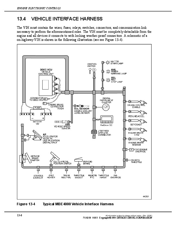
5.2.1 CPC Vehicle Interface Harness…..3947
5.2.2 VIH Wiring…..3951
5.2.3 Power Supply – 12 Volt System…..3959
5.2.4 Fuses…..3962
5.2.5 Connectors…..3963
5.3 Wires and Wiring…..3965
5.4 Conduit and Loom…..3977
5.5 Tape and Taping…..3978
5.6 Sensors…..3978
5.6.1 Factory-installed Sensors…..3979
5.6.2 OEM-installed Sensors…..3979
5.7 Lamps…..3988
5.7.1 Amber Warning Lamp (AWL)…..3988
5.7.2 Cruise Active Lamp…..3988
5.7.3 Deceleration Lamp…..3989
5.7.4 Fuel Filter Restriction Lamp…..3990
5.7.5 Low Battery Voltage Lamp…..3991
5.7.6 Low Coolant Level Lamp…..3992
5.7.7 Low Oil Pressure Lamp…..3993
5.7.8 Malfunction Indicator Lamp (MIL)…..3994
5.7.9 Optimized Idle Active Lamp…..3994
5.7.10 Red Stop Lamp…..3995
5.7.11 Wait-to-Start Lamp…..3996
5.7.12 Water-In-Fuel Lamp (R2.0 or Later)…..3997
6 Inputs and Outputs…..3999
6.1 Digital Inputs Overview – CPC…..3999
6.1.1 Inputs – Air Condition Status…..3999
6.1.2 Inputs – Auxiliary Shutdown #1…..4000
6.1.3 Inputs – Clutch Switch…..4001
6.1.4 Inputs – Cruise Control ON/OFF Switch…..4002
6.1.5 Inputs – Cruise Control Resume/Accel Switch and Set/Coast Switch…..4002
6.1.6 Inputs – Diagnostic Request Switch…..4003
6.1.7 Inputs – Dual-Speed Axle Switch…..4004
6.1.8 Inputs – Engine Brake Disable…..4004
6.1.9 Inputs – Engine Brake Low and Medium…..4005
6.1.10 Inputs – Fan Override…..4006
6.1.11 Inputs – Fast Engine Heat-Up Switch…..4006
6.1.12 Inputs – Idle Validation 1 and Idle Validation 2…..4007
6.1.13 Inputs – Limiters for Torque, Engine Speed, and Vehicle Speed…..4007
6.1.14 Inputs – Optimized Idle Hood Tilt Switch…..4007
6.1.15 Inputs – Optimized Idle Thermostat…..4007
6.1.16 Inputs – Park Brake Switch…..4008
6.1.17 Inputs – Remote Throttle Select Switch…..4008
6.1.18 Inputs – Remote PTO Switch…..4009
6.1.19 Inputs – RPM Freeze…..4010
6.1.20 Inputs – Service Brake Released Switch…..4010
6.1.21 Inputs – Stop Engine Override…..4011
6.1.22 Inputs – Throttle Inhibit…..4011
6.1.23 Inputs – Transmission Neutral Switch…..4012
6.1.24 Inputs – Transmission Retarder Active…..4012
6.2 Switch Inputs Received Over J1939 Data Link…..4013
6.3 Digital Outputs Overview – CPC…..4015
6.3.1 Outputs – Amber Warning Lamp…..4016
6.3.2 Outputs – Cruise Active Lamp…..4016
6.3.3 Outputs – Deceleration Lamp…..4017
6.3.4 Outputs – Engine Brake Active…..4018
6.3.5 Outputs – Fuel Filter Restriction Lamp…..4019
6.3.6 Outputs – Low Battery Voltage Lamp…..4019
6.3.7 Outputs – Low Coolant Level Lamp…..4020
6.3.8 Outputs – Low Oil Pressure Lamp…..4021
6.3.9 Outputs – Malfunction Indicator Lamp (MIL)…..4022
6.3.10 Outputs – Optimized Idle Active Lamp…..4022
6.3.11 Outputs – Optimized Idle Alarm…..4023
6.3.12 Outputs – Red Stop Lamp…..4024
6.3.13 Outputs – Vehicle Power Shutdown…..4024
6.3.14 Outputs – Wait to Start Lamp…..4025
6.3.15 Outputs – Water-In-Fuel Lamp…..4025
6.4 PWM Outputs – CPC…..4026
7 Features…..4028
7.1 Acceleration Limiter…..4028
7.2 Common Driver Reward…..4028
7.3 Cruise Control…..4031
7.4 Diagnostics…..4040
7.5 Dual Speed Axle…..4043
7.6 Engine Brake Controls – EuroIV DD15…..4044
7.7 Engine Protection…..4049
7.8 Engine Ratings…..4051
7.9 Engine Starter Control…..4052
7.10 Fan Control…..4055
7.11 Fleet Management…..4072
7.12 Fuel Economy Incentive…..4078
7.13 Idle Adjust…..4080
7.14 Idle Protection…..4081
7.15 Idle Shutdown Timer and PTO Shutdown…..4082
7.16 Limiters…..4088
7.17 Low Gear Torque Reduction…..4090
7.18 Optimized Idle…..4092
7.19 PasSmart…..4099
7.20 Passwords…..4101
7.21 Progressive Shift…..4102
7.22 Soft Cruise…..4105
7.23 Starter Lockout…..4106
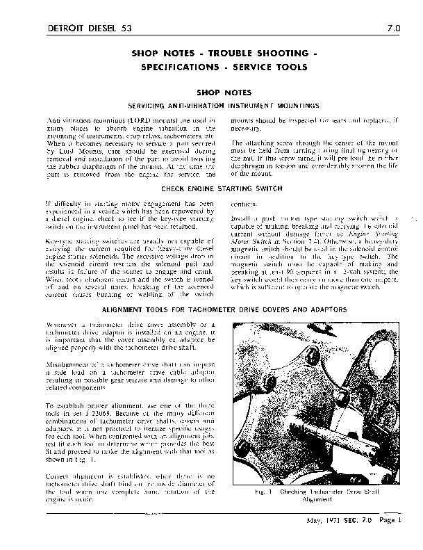
7.24 Tachometer Drive…..4107
7.25 Throttle Control / Governors…..4108
7.26 Transmission Interface…..4122
7.27 Vehicle Speed Limiting…..4126
7.28 Vehicle Speed Sensor Anti-Tampering…..4128
8 Communication Protocols…..4130
8.1 Communication Protocols – Overview…..4130
8.2 SAE J1939 Messages and Message Format…..4130
8.2.1 SAE J1939 Supported Messages…..4131
9 Appendix A: Harness Wiring Diagrams…..4173
9.1 Harness Wiring Diagrams…..4173
10 Appendix B: Parameter Lists…..4178
10.1 Parameter List…..4178
11 Appendix C: Acronyms…..4197
11.1 Acronyms…..4197
Det_Trans_ddc-svc-man-0128…..4199
1 California Proposition 65 Warning and Engine Idle Notice…..4201
2 Attention…..4202
3 Abstract…..4203
4 Introduction…..4204
4.1 Introduction…..4204
5 Safety Precautions…..4205
5.1 Safety Precautions…..4205
6 Hardware and Wiring…..4209
6.1 Transmission Control Module (TCM)…..4209
6.2 TCM Electrical Limits…..4209
6.3 TCM 21-Pin Connectors…..4209
6.4 Wires and Wiring…..4213
6.5 Conduit and Loom…..4222
6.6 Tape and Taping…..4223
6.7 Power Supply – 12-Volt System…..4223
6.8 Fuses…..4224
6.9 Communications – Proprietary Powertrain – CAN Data Link…..4224
6.10 Lamps/Instrument Cluster Messages/Driver Interface…..4228
6.10.1 Check Trans Lamp…..4228
6.10.2 Engine Retarder Enabled Lamp…..4230
6.10.3 Hill Start Aid Lamp…..4231
6.10.4 Transmission Oil Temperature Gauge…..4232
6.11 Detroit Transmission Sensors and Actuators…..4233
7 Features…..4234
7.1 Active Driveline Protection…..4234
7.2 Auto Neutral Feature…..4234
7.3 Creep Mode…..4234
7.4 Hill Start Aid (Optional)…..4235
7.5 Driving Modes…..4236
7.6 Dual Channel Analog Accelerator Pedal Position Sensor…..4238
7.7 eCoast Feature…..4243
7.8 Engine Brake Controls…..4244
8 Communication Protocols…..4248
8.1 Communication Protocols – Overview…..4248
8.1.1 SAE J1939 Messages and Message Format…..4248
8.2 Required SAE J1939 Detroit Transmission Messages (Drivers Interface)…..4249
8.3 SAE J1939 Detroit Transmission Supported Messages…..4252
9 Transmission Special Requirements…..4264
9.1 Detroit Transmission Air Supply Requirements…..4264
9.2 Detroit Transmission Required Learning Routines and TCM Required Information…..4266
10 Appendix A: Detroit Transmissions TCM Wiring Harness…..4269
10.1 Detroit Transmission TCM Wiring Harness…..4269
11 Appendix B: Parameter Lists…..4271
11.1 PARAMETER LIST…..4271
12 Appendix C: Acronyms…..4277
12.1 ACRONYMS…..4277
Detroit Diesel – Cooling System – Technicians Guide…..4279
Detroit Diesel – DDEC II to III-IV Conversion …..4313
freightliner.com…..0
18SP546REV.PDF – Install DDEC II to DDEC IV Wire Harness and Hardware Conversion Kit on 1991-1993 Series 60® On-Highway Manual Transmission Trucks…..4313
…..4313
18SP546* – Install DDEC II to DDEC IV Wire Harnes…..4313
Hardware Conversion Kit on 1991-1993 Series 60® �…..4313
Detroit Diesel – DDEC VI – Application And Installation Manual…..4321
Detroit Diesel – DDEC VI SERIES 60 MCM EGR Engine Harness Schematic…..4859
Detroit Diesel – Fuel System Bulletin – MBE 4000-06a…..4860
Detroit Diesel – Low Power Bulletin – MBE4000-07…..4936
Detroit Diesel – MBE 4000 Application And Installation ch13…..4976
Detroit Diesel – MBE 4000 ENGINE EPA04 OPERATOR'S MANUAL – DDC-SVC-MAN-0056…..4986
Detroit_dd13…..5096
Diesel Exhaust Fluid Tank Header Unit…..5262
39.1 Description and Operation of the Diesel Exhaust Fluid Tank Header Unit…..5262
39.2 Removal of the EPA10 13 and 23 Gallon Diesel Exhaust Fluid Tank Header Unit…..5264
39.3 Installation of the EPA10 13 and 23 Gallon Diesel Exhaust Fluid Tank Header Unit…..5267
39.4 Removal of the GHG14 13 and 23 Gallon Diesel Exhaust Fluid Tank Header Unit…..5269
39.5 Installation of the GHG14 13 and 23 Gallon Diesel Exhaust Fluid Tank Header Unit…..5271
39.6 Removal of the GHG14 Six-Gallon Diesel Exhaust Fluid Tank Header…..5273
39.7 Installation of the GHG14 Six-Gallon Diesel Exhaust Fluid Tank Header…..5274
EPA10/GHG14 Diesel Exhaust Fluid Tank Header Unit…..5275
39.1 Description and Operation of the Diesel Exhaust Fluid Tank Header Unit…..5275
39.2 Removal of the EPA10 13 and 23 Gallon Diesel Exhaust Fluid Tank Header Unit…..5277
39.3 Installation of the EPA10 13 and 23 Gallon Diesel Exhaust Fluid Tank Header Unit…..5280
39.4 Removal of the GHG14 13 and 23 Gallon Diesel Exhaust Fluid Tank Header Unit…..5282
39.5 Installation of the GHG14 13 and 23 Gallon Diesel Exhaust Fluid Tank Header Unit…..5284
39.6 Removal of the GHG14 Six-Gallon Diesel Exhaust Fluid Tank Header…..5286
39.7 Installation of the GHG14 Six-Gallon Diesel Exhaust Fluid Tank Header…..5287
Diesel Exhaust Fluid Tank…..5288
40.1 Description and Operation of the Diesel Exhaust Fluid Tank…..5288
40.2 Description and Operation of the EPA10 Diesel Exhaust Fluid Heating…..5289
40.3 Removal of the Six-Gallon Diesel Exhaust Fluid Tank…..5290
40.4 Installation of the Six-Gallon Diesel Exhaust Fluid Tank…..5293
40.5 Removal of the GHG14 Six-Gallon Diesel Exhaust Fluid Tank…..5295
40.6 Installation of the GHG14 Six-Gallon Diesel Exhaust Fluid Tank…..5297
40.7 Removal of the 13 and 23 Gallon Diesel Exhaust Fluid Tank…..5299
40.8 Installation of the 13 and 23 Gallon Diesel Exhaust Fluid Tank…..5302
40.9 Removal of the GHG14 13 and 23 Gallon Diesel Exhaust Fluid Tank…..5304
40.10 Installation of the GHG14 13 and 23 Gallon Diesel Exhaust Fluid Tank…..5306
EPA10/GHG14 Diesel Exhaust Fluid Tank…..5308
40.1 Description and Operation of the Diesel Exhaust Fluid Tank…..5308
40.2 Description and Operation of the EPA10 Diesel Exhaust Fluid Heating…..5309
40.3 Removal of the Six-Gallon Diesel Exhaust Fluid Tank…..5310
40.4 Installation of the Six-Gallon Diesel Exhaust Fluid Tank…..5313
40.5 Removal of the GHG14 Six-Gallon Diesel Exhaust Fluid Tank…..5315
40.6 Installation of the GHG14 Six-Gallon Diesel Exhaust Fluid Tank…..5317
40.7 Removal of the 13 and 23 Gallon Diesel Exhaust Fluid Tank…..5319
40.8 Installation of the 13 and 23 Gallon Diesel Exhaust Fluid Tank…..5322
40.9 Removal of the GHG14 13 and 23 Gallon Diesel Exhaust Fluid Tank…..5324
40.10 Installation of the GHG14 13 and 23 Gallon Diesel Exhaust Fluid Tank…..5326
Diesel Exhaust Fluid and Coolant Lines…..5328
41.1 Removal of the Diesel Exhaust Fluid Lines (Tank to Pump)…..5328
41.2 Installation of the Diesel Exhaust Fluid Lines (Tank to Pump)…..5330
41.3 Removal of the Diesel Exhaust Fluid Line Connections…..5331
41.4 Installation of the Diesel Exhaust Fluid Line Connections…..5332
41.5 Removal of DEF Supply Unit Coolant Line Fittings…..5333
41.6 Installation of the DEF Supply Unit Coolant Line Fittings…..5334
EPA10 Diesel Exhaust Fluid and Coolant Lines…..5335
41.1 Removal of the Diesel Exhaust Fluid Lines (Tank to Pump)…..5335
41.2 Installation of the Diesel Exhaust Fluid Lines (Tank to Pump)…..5337
41.3 Removal of the Diesel Exhaust Fluid Line Connections…..5338
41.4 Installation of the Diesel Exhaust Fluid Line Connections…..5339
41.5 Removal of DEF Supply Unit Coolant Line Fittings…..5340
41.6 Installation of the DEF Supply Unit Coolant Line Fittings…..5341
Diesel Oxidation Catalyst Inlet Pressure Sensor…..5342
50.1 Removal of the EPA10 Diesel Oxidation Catalyst Inlet Pressure Sensor…..5342
50.2 Installation of the EPA10 Diesel Oxidation Catalyst Inlet Pressure Sensor…..5344
50.3 Removal of the EPA10 Diesel Oxidation Catalyst Inlet Pressure Sensor without Sensor Box…..5345
50.4 Installation of the EPA10 Diesel Oxidation Catalyst Inlet Pressure Sensor without Sensor Box…..5347
50.5 Removal of the EPA10 Diesel Oxidation Catalyst Inlet Pressure Sensor with Sensor Box…..5348
50.6 Installation of the EPA10 Diesel Oxidation Catalyst Inlet Pressure Sensor with Sensor Box…..5350
EPA10 Diesel Oxidation Catalyst Inlet Pressure Sensor…..5352
50.1 Removal of the EPA10 Diesel Oxidation Catalyst Inlet Pressure Sensor…..5352
50.2 Installation of the EPA10 Diesel Oxidation Catalyst Inlet Pressure Sensor…..5354
50.3 Removal of the EPA10 Diesel Oxidation Catalyst Inlet Pressure Sensor without Sensor Box…..5355
50.4 Installation of the EPA10 Diesel Oxidation Catalyst Inlet Pressure Sensor without Sensor Box…..5357
50.5 Removal of the EPA10 Diesel Oxidation Catalyst Inlet Pressure Sensor with Sensor Box…..5358
50.6 Installation of the EPA10 Diesel Oxidation Catalyst Inlet Pressure Sensor with Sensor Box…..5360
EPA07 10 GHG14 Exhaust – EGR – ATS Manual (DDC-SVC-MAN-0083)_…..5362
Exhaust Manifold…..5362
2.1 Description and Operation of the Exhaust Manifold and Related Parts…..5362
DD13 Exhaust Manifold…..5362
DD15 Exhaust Manifold…..5362
GHG14 DD15 AT Exhaust Manifold…..5363
EPA10 DD16 High-Horsepower Exhaust Manifold…..5364
2.2 Removal of the Exhaust Manifold…..5366
2.3 Removal of the GHG14 DD15 Asymmetrical Turbocharger Exhaust Manifold…..5367
2.4 Inspection of an Assembled Exhaust Manifold…..5368
2.5 Inspection of a Disassembled Exhaust Manifold…..5370
2.6 Disassembly of the Exhaust Manifold…..5371
2.7 Assembly of the Exhaust Manifold…..5372
2.8 Cleaning of the Exhaust Manifold…..5373
2.9 Installation of the Exhaust Manifold…..5374
2.10 Installation of the GHG14 DD15 Asymmetrical Turbocharger Exhaust Manifold…..5377
EPA07 Aftertreatment Device Cleaning and Maintenance…..5379
33.2 Requirements – EPA07…..5379
Service Record…..5379
EPA07 Aftertreatment Device Cleaning and Maintenance…..5380
33.1 Accumulated Ash – EPA07…..5380
33.2 EPA07 Diesel Particulate Filter Ash Measurement Procedure…..5381
33.3 Requirements – EPA07…..5386
Service Record…..5386
EPA07 Aftertreatment Device Removal and Installation on Vehicle…..5387
34.1 Removal of the EPA07 Aftertreatment Device from the Vehicle…..5387
34.2 Installation of the EPA07 Aftertreatment Device…..5393
EPA07 Aftertreatment Device Removal and Installation on Vehicle…..5395
34.1 Removal of the EPA07 Aftertreatment Device from the Vehicle…..5395
34.2 Installation of the EPA07 Aftertreatment Device…..5401
EPA07 Aftertreatment Device Sensors…..5403
EPA07 Aftertreatment Device Sensors…..5403
32.1 Description and Operation of the EPA07 Aftertreatment Device Temperature Sensors…..5403
32.2 Removal of the EPA07 Temperature Sensors…..5404
32.3 Installation of the EPA07 Temperature Sensors…..5405
32.4 Removal of the EPA07 Pressure Sensors…..5406
32.5 Installation of the EPA07 Pressure Sensors…..5407
EPA07 Aftertreatment System Overview…..5408
EPA07 Aftertreatment System Overview…..5408
31.1 Overview of EPA07 Aftertreatment System…..5408
31.2 Description and Operation of the EPA07 Aftertreatment Device…..5409
31.3 Description and Operation of the Diesel Particulate Filter…..5411
31.4 EPA07 Aftertreatment Operating Requirements…..5412
31.5 EPA07 Aftertreatment System Component Overview…..5413
31.6 EPA07 Aftertreatment Regeneration Strategy…..5415
EPA07 DD15 Regeneration Strategy…..5415
EPA07 DD15 Idle Timing…..5415
Passive Regeneration…..5416
Active Regeneration…..5416
Parked Regeneration…..5417
31.7 Performing a Parked Regeneration – EPA07…..5419
31.8 Unable to Perform a Parked Regeneration – EPA07…..5421
31.9 Instrument Panel Lamps…..5423
Amber Warning Lamp…..5423
Red Stop Lamp…..5423
Diesel Particulate Filter Regeneration Lamp…..5423
High Exhaust System Temperature Lamp…..5424
Malfunction Indicator Lamp…..5424
EPA07_DDECVIddc-svc-man-0054…..5425
1 California Proposition 65 Warning and Engine Idle Notice…..5428
2 Attention…..5429
3 Abstract…..5430
4 Introduction…..5431
4.1 Introduction…..5431
5 Safety Precautions…..5432
5.1 Safety Precautions…..5432
6 Hardware and Wiring…..5436
6.1 Motor Control Module…..5436
6.1.1 Engine Harness…..5436
6.1.2 DPF Harness…..5456
6.2 Common Powertrain Controller…..5462
6.2.1 CPC Vehicle Interface Harness…..5464
6.2.2 VIH Wiring…..5469
6.2.3 Power Supply – 12 Volt System…..5499
6.2.4 Fuses…..5501
6.2.5 Connectors…..5502
6.3 Wires and Wiring…..5505
6.4 Conduit and Loom…..5517
6.5 Tape and Taping…..5518
6.6 Sensors…..5518
6.6.1 Factory-installed Sensors…..5519
6.6.2 OEM-installed Sensors…..5524
6.7 Lamps…..5534
6.7.1 AGS2 Backup Lamp…..5534
6.7.2 AGS2 Check Trans Lamp…..5535
6.7.3 AGS2 Trans Temp Lamp…..5536
6.7.4 Amber Warning Lamp (AWL)…..5537
6.7.5 Cruise Active Lamp…..5538
6.7.6 Deceleration Lamp…..5538
6.7.7 DPF Regeneration Lamp…..5539
6.7.8 Fuel Filter Restriction Lamp…..5540
6.7.9 High Exhaust System Temperature Lamp…..5541
6.7.10 Low Battery Voltage Lamp…..5542
6.7.11 Low Coolant Level Lamp…..5543
6.7.12 Low Oil Pressure Lamp…..5544
6.7.13 Malfunction Indicator Lamp (MIL)…..5545
6.7.14 Optimized Idle Active Lamp…..5545
6.7.15 Red Stop Lamp…..5546
6.7.16 Wait-to-Start Lamp…..5547
6.7.17 Water-In-Fuel Lamp (R2.0 or Later)…..5548
7 Inputs and Outputs…..5550
7.1 Digital Inputs Overview – CPC…..5550
7.1.1 Inputs – Air Condition Status…..5550
7.1.2 Inputs – ABS Active…..5551
7.1.3 Inputs – Auxiliary Shutdown #1…..5552
7.1.4 Inputs – Clutch Switch…..5553
7.1.5 Inputs – Cruise Control ON/OFF Switch…..5554
7.1.6 Inputs – Cruise Control Resume/Accel Switch and Set/Coast Switch…..5554
7.1.7 Inputs – Diagnostic Request Switch…..5555
7.1.8 Inputs – DPF Regeneration Inhibit Switch and Regen Switch (CPC R2.0 or Later and MCM V61 for Series 60, MCM V8 for MBE or Later)…..5556
7.1.9 Inputs – Dual-Speed Axle Switch…..5558
7.1.10 Inputs – Engine Brake Disable…..5558
7.1.11 Inputs – Engine Brake Low and Medium…..5559
7.1.12 Inputs – Evobus 5-Stage Retarder…..5559
7.1.13 Inputs – Fan Override…..5561
7.1.14 Inputs – Fast Engine Heat-Up Switch…..5561
7.1.15 Inputs – Idle Validation 1 and Idle Validation 2…..5562
7.1.16 Inputs – Limiters for Torque, Engine Speed, and Vehicle Speed…..5562
7.1.17 Inputs – Optimized Idle Hood Tilt Switch…..5562
7.1.18 Inputs – Optimized Idle Thermostat…..5563
7.1.19 Inputs – Park Brake Switch…..5563
7.1.20 Inputs – Regen Switch…..5564
7.1.21 Inputs – Remote Throttle Select Switch…..5564
7.1.22 Inputs – Remote PTO Switch…..5565
7.1.23 Inputs – RPM Freeze…..5565
7.1.24 Inputs – Service Brake Released Switch…..5566
7.1.25 Inputs – Stop Engine Override…..5566
7.1.26 Inputs – Throttle Inhibit…..5567
7.1.27 Inputs – Transmission Neutral Switch…..5567
7.1.28 Inputs – Transmission Retarder Active…..5568
7.2 Switch Inputs Received Over J1939 Data Link…..5568
7.3 Digital Outputs Overview – CPC…..5571
7.3.1 Outputs – AGS2 Backup Lamp…..5572
7.3.2 Outputs – AGS2 Check Trans Lamp…..5573
7.3.3 Outputs – AGS2 Trans Temp Lamp…..5573
7.3.4 Outputs – Amber Warning Lamp…..5574
7.3.5 Outputs – Cruise Active Lamp…..5574
7.3.6 Outputs – Deceleration Lamp…..5575
7.3.7 Outputs – DPF Regeneration Lamp (Hardwired and J1939)…..5576
7.3.8 Outputs – Engine Brake Active…..5576
7.3.9 Outputs – Ether Start…..5577
7.3.10 Outputs – Fuel Filter Restriction Lamp…..5578
7.3.11 Outputs – High Exhaust System Temperature (HEST) Lamp (Hardwired and J1939)…..5578
7.3.12 Outputs – Low Battery Voltage Lamp…..5579
7.3.13 Outputs – Low Coolant Level Lamp…..5580
7.3.14 Outputs – Low Oil Pressure Lamp…..5581
7.3.15 Outputs – Malfunction Indicator Lamp (MIL)…..5582
7.3.16 Outputs – Optimized Idle Active Lamp…..5582
7.3.17 Outputs – Optimized Idle Alarm…..5583
7.3.18 Outputs – Red Stop Lamp…..5584
7.3.19 Outputs – Starter Lockout…..5584
7.3.20 Outputs – Top2 Shift Solenoid…..5585
7.3.21 Outputs – Top2 Shift Lockout Solenoid…..5586
7.3.22 Outputs – Vehicle Power Shutdown…..5587
7.3.23 Outputs – Wait to Start Lamp…..5587
7.3.24 Outputs – Water-In-Fuel Lamp…..5588
7.4 Analog Outputs – CPC…..5589
7.5 PWM Outputs – CPC…..5590
8 Features…..5592
8.1 Acceleration Limiter…..5592
8.2 Auto-Elevate Idle…..5592
8.3 Clean Idle Limiting Feature…..5593
8.4 Clean Idle…..5595
8.5 Cold Start – MBE900, MBE4000, DD13 and DD15…..5595
8.6 Common Driver Reward…..5599
8.7 Cruise Control…..5601
8.8 Diagnostics…..5610
8.9 Dual Speed Axle…..5614
8.10 Engine Brake Controls – MBE 900 and MBE 4000…..5615
8.11 Engine Brake Controls – Series 60, DD13 and DD15…..5631
8.12 Engine Protection…..5636
8.13 Engine Ratings…..5638
8.14 Engine Starter Control…..5641
8.15 Ether Start – Series 60…..5643
8.16 Fan Control…..5648
8.17 Fleet Management…..5665
8.18 Fuel Economy Incentive…..5671
8.19 Idle Adjust…..5673
8.20 Idle Protection…..5674
8.21 Idle Shutdown Timer and PTO Shutdown…..5675
8.22 Limiters…..5681
8.23 Low Gear Torque Reduction…..5683
8.24 Optimized Idle…..5685
8.25 Parked Regeneration…..5692
8.26 PasSmart…..5695
8.27 Passwords…..5697
8.28 Progressive Shift…..5698
8.29 Soft Cruise…..5701
8.30 Starter Lockout…..5702
8.31 Tachometer Drive…..5704
8.32 Throttle Control / Governors…..5704
8.33 Transmission Interface…..5719
8.34 Vehicle Speed Limiting…..5730
8.35 Vehicle Speed Sensor Anti-Tampering…..5732
9 Communication Protocols…..5734
9.1 Communication Protocols – Overview…..5734
9.2 SAE J1587 Data Link…..5734
9.3 SAE J1939 Messages and Message Format…..5757
9.3.1 SAE J1939 Supported Messages…..5758
10 Appendix A: Harness Wiring Diagrams…..5803
10.1 Harness Wiring Diagrams…..5803
11 Appendix B: Parameter Lists…..5804
11.1 Parameter List…..5804
12 Appendix C: Acronyms…..5823
12.1 Acronyms…..5823
EPA10 1-BOX Sensor Box…..5825
48.1 Removal of the 1-BOX™ Sensor Box…..5825
48.2 Installation of the 1-BOX™ Sensor Box…..5827
EPA10 1-BOX Sensor Box…..5829
48.1 Removal of the 1-BOX™ Sensor Box…..5829
48.2 Installation of the 1-BOX™ Sensor Box…..5831
EPA10 1-BOX from the Vehicle…..5833
54.1 Removal of the 1-BOX™ from the Vehicle…..5833
54.2 Installation of the 1-BOX™ to the Vehicle…..5844
EPA10 1-BOX from the Vehicle…..5856
54.1 Removal of the 1-BOX™ from the Vehicle…..5856
54.2 Installation of the 1-BOX™ to the Vehicle…..5867
EPA10 2-BOX from the Vehicle…..5880
56.1 2-Box (2V2) Additional Removal Information…..5880
56.2 Removal of the 2-Box (2V2) from the Vehicle…..5881
56.3 Installation of the 2-Box (2V2) to the Vehicle…..5882
EPA10 2-BOX from the Vehicle…..5885
56.1 2-Box (2V2) Additional Removal Information…..5885
56.2 Removal of the 2-Box (2V2) from the Vehicle…..5886
56.3 Installation of the 2-Box (2V2) to the Vehicle…..5887
EPA10 Diesel Exhaust Fluid Metering Unit…..5890
45.1 Description and Operation of the Diesel Exhaust Fluid Metering Unit…..5890
45.2 Compressed-Air Assisted Diesel Exhaust Fluid Supply Function…..5891
45.3 Removal of the Diesel Exhaust Fluid Metering Unit…..5892
45.4 Installation of the Diesel Exhaust Fluid Metering Unit…..5896
45.5 Removal of the Diesel Exhaust Fluid Screen…..5900
45.6 Installation of the Diesel Exhaust Fluid Screen…..5901
45.7 Removal of the Diesel Exhaust Fluid Metering Unit Compressed Air Supply Screen…..5902
45.8 Installation of the Diesel Exhaust Fluid Metering Unit Compressed Air Supply Screen…..5903
45.9 Removal of the Diesel Exhaust Fluid Pressure Sensor…..5904
45.10 Installation of the Diesel Exhaust Fluid Pressure Sensor…..5905
45.11 Removal of the Diesel Exhaust Fluid Temperature Sensor…..5906
45.12 Installation of the Diesel Exhaust Fluid Temperature Sensor…..5907
45.13 Removal of the Diesel Exhaust Fluid Metering Unit Air Pressure Sensor…..5908
45.14 Installation of the Diesel Exhaust Fluid Metering Unit Air Pressure Sensor…..5909
45.15 Removal of the Diesel Exhaust Fluid Metering Unit Doser Heater…..5910
45.16 Installation of the Diesel Exhaust Fluid Metering Unit Doser Heater…..5911
45.17 Removal of the Diesel Exhaust Fluid Metering Unit Diffuser Heater…..5912
45.18 Installation of the Diesel Exhaust Fluid Metering Unit Diffuser Heater…..5913
EPA10 Diesel Exhaust Fluid Metering Unit…..5914
45.1 Description and Operation of the Diesel Exhaust Fluid Metering Unit…..5914
45.2 Compressed-Air Assisted Diesel Exhaust Fluid Supply Function…..5915
45.3 Removal of the Diesel Exhaust Fluid Metering Unit…..5916
45.4 Installation of the Diesel Exhaust Fluid Metering Unit…..5920
45.5 Removal of the Diesel Exhaust Fluid Screen…..5924
45.6 Installation of the Diesel Exhaust Fluid Screen…..5925
45.7 Removal of the Diesel Exhaust Fluid Metering Unit Compressed Air Supply Screen…..5926
45.8 Installation of the Diesel Exhaust Fluid Metering Unit Compressed Air Supply Screen…..5927
45.9 Removal of the Diesel Exhaust Fluid Pressure Sensor…..5928
45.10 Installation of the Diesel Exhaust Fluid Pressure Sensor…..5929
45.11 Removal of the Diesel Exhaust Fluid Temperature Sensor…..5930
45.12 Installation of the Diesel Exhaust Fluid Temperature Sensor…..5931
45.13 Removal of the Diesel Exhaust Fluid Metering Unit Air Pressure Sensor…..5932
45.14 Installation of the Diesel Exhaust Fluid Metering Unit Air Pressure Sensor…..5933
45.15 Removal of the Diesel Exhaust Fluid Metering Unit Doser Heater…..5934
45.16 Installation of the Diesel Exhaust Fluid Metering Unit Doser Heater…..5935
45.17 Removal of the Diesel Exhaust Fluid Metering Unit Diffuser Heater…..5936
45.18 Installation of the Diesel Exhaust Fluid Metering Unit Diffuser Heater…..5937
EPA10 Diesel Exhaust Fluid Nozzle…..5938
46.1 Description and Operation of the Diesel Exhaust Fluid Nozzle…..5938
46.2 Removal of the Diesel Exhaust Fluid Nozzle…..5939
46.3 Cleaning of the Diesel Exhaust Fluid Nozzle…..5941
46.4 Installation of the Diesel Exhaust Fluid Nozzle…..5942
EPA10 Diesel Exhaust Fluid Nozzle…..5943
46.1 Description and Operation of the Diesel Exhaust Fluid Nozzle…..5943
46.2 Removal of the Diesel Exhaust Fluid Nozzle…..5944
46.3 Cleaning of the Diesel Exhaust Fluid Nozzle…..5946
46.4 Installation of the Diesel Exhaust Fluid Nozzle…..5947
EPA10 Diesel Exhaust Fluid Pump Module and Components…..5948
42.1 Description and Operation of the Diesel Exhaust Fluid Pump Assembly…..5948
42.2 Removal of the Diesel Exhaust Fluid Pump Module…..5949
42.3 Installation of the Diesel Exhaust Fluid Pump Module…..5955
42.4 Flushing of the Diesel Exhaust Fluid System…..5959
42.5 Removal of the Diesel Exhaust Fluid Pump Module Filter Screen…..5960
42.6 Installation of the Diesel Exhaust Fluid Pump Module Filter Screen…..5962
42.7 Removal of the Diesel Exhaust Fluid Pump Module Pneumatic Switching Valve…..5964
42.8 Installation of the Diesel Exhaust Fluid Pump Module Pneumatic Switching Valve…..5968
42.9 Removal of the Diesel Exhaust Fluid Pump Module Filter…..5970
42.10 Installation of the Diesel Exhaust Fluid Pump Module Filter…..5973
42.11 Removal of the Diesel Exhaust Fluid Pump Module Air Bladder…..5975
42.12 Installation of the Diesel Exhaust Fluid Pump Module Air Bladder…..5976
EPA10 Diesel Exhaust Fluid Pump Module and Components…..5977
42.1 Description and Operation of the Diesel Exhaust Fluid Pump Assembly…..5977
42.2 Removal of the Diesel Exhaust Fluid Pump Module…..5978
42.3 Installation of the Diesel Exhaust Fluid Pump Module…..5984
42.4 Flushing of the Diesel Exhaust Fluid System…..5988
42.5 Removal of the Diesel Exhaust Fluid Pump Module Filter Screen…..5989
42.6 Installation of the Diesel Exhaust Fluid Pump Module Filter Screen…..5991
42.7 Removal of the Diesel Exhaust Fluid Pump Module Pneumatic Switching Valve…..5993
42.8 Installation of the Diesel Exhaust Fluid Pump Module Pneumatic Switching Valve…..5997
42.9 Removal of the Diesel Exhaust Fluid Pump Module Filter…..5999
42.10 Installation of the Diesel Exhaust Fluid Pump Module Filter…..6002
42.11 Removal of the Diesel Exhaust Fluid Pump Module Air Bladder…..6004
42.12 Installation of the Diesel Exhaust Fluid Pump Module Air Bladder…..6005
EPA10 Diesel Particulate Filter…..6006
52.1 Removal of the EPA10 Diesel Particulate Filter…..6006
52.2 Installation of the EPA10 Diesel Particulate Filter…..6017
EPA10 Diesel Particulate Filter…..6026
52.1 Removal of the EPA10 Diesel Particulate Filter…..6026
52.2 Installation of the EPA10 Diesel Particulate Filter…..6038
EPA10_DDEC10ddc-svc-man-0045…..6047
1 California Proposition 65 Warning and Engine Idle Notice…..6050
2 Attention…..6051
3 Abstract…..6052
4 Introduction…..6053
4.1 Introduction…..6053
5 Safety Precautions…..6054
5.1 Safety Precautions…..6054
6 Hardware and Wiring…..6058
6.1 Motor Control Module2…..6058
6.1.1 Engine Harness…..6059
6.2 Common Powertrain Controller 2+…..6073
6.2.1 CPC2+ Vehicle Interface harness…..6075
6.2.2 VIH Wiring…..6077
6.2.3 Power Supply – 12 Volt System…..6095
6.2.4 Fuses…..6097
6.3 Aftertreatment Control Module2…..6098
6.3.1 Aftertreatment and SCR System…..6101
6.4 Vehicle Interface Wiring…..6106
6.4.1 VIH to MCM2 Connector Wiring…..6108
6.4.2 VIH to ACM2 Connector Wiring…..6109
6.5 On-board Diagnostics…..6132
6.5.1 Data Link Connector Location…..6132
6.5.2 Lamp Requirements…..6134
6.5.3 Electronic Transmission Requirements…..6136
6.6 Wires and Wiring…..6136
6.7 Conduit and Loom…..6149
6.8 Tape and Taping…..6150
6.9 Sensors and Actuators…..6150
6.9.1 Factory-installed Sensors…..6151
6.9.2 Aftertreatment and SCR Sensors…..6151
6.9.3 OEM-installed Sensors…..6153
6.10 Lamps…..6162
6.10.1 Amber Warning Lamp (AWL)…..6164
6.10.2 Cruise Active Lamp…..6165
6.10.3 Deceleration Lamp…..6166
6.10.4 Diesel Exhaust Fluid (DEF) Low Lamp…..6167
6.10.5 DPF Regeneration Lamp…..6170
6.10.6 Fuel Filter Restriction Lamp…..6170
6.10.7 High Exhaust System Temperature Lamp…..6171
6.10.8 Low Battery Voltage Lamp…..6172
6.10.9 Low Coolant Level Lamp…..6173
6.10.10 Low Oil Pressure Lamp…..6174
6.10.11 Malfunction Indicator Lamp (MIL)…..6175
6.10.12 Optimized Idle Active Lamp…..6176
6.10.13 DEF Purge-in-Process (PIP) Lamp…..6177
6.10.14 Red Stop Lamp…..6178
6.10.15 Wait-to-Start Lamp…..6179
6.10.16 Water-In-Fuel Lamp…..6179
7 Inputs and Outputs…..6182
7.1 Digital Inputs Overview – CPC2+…..6182
7.1.1 Inputs – Air Condition Status…..6183
7.1.2 Inputs – Auxiliary Shutdown #1…..6183
7.1.3 Inputs – Clutch Switch…..6184
7.1.4 Inputs – Cruise Control ON/OFF Switch…..6185
7.1.5 Inputs – Cruise Control Resume/Accel Switch and Set/Coast Switch…..6185
7.1.6 Inputs – DPF Regeneration Inhibit Switch and Regen Switch…..6186
7.1.7 Inputs – Dual-Speed Axle Switch…..6188
7.1.8 Inputs – Engine Brake Disable…..6189
7.1.9 Inputs – Engine Brake Low and Medium…..6190
7.1.10 Inputs – Fan Override…..6191
7.1.11 Inputs – Idle Validation 1 and Idle Validation 2…..6191
7.1.12 Inputs – Limiters for Torque, Engine Speed, and Vehicle Speed…..6191
7.1.13 Inputs – Optimized Idle Hood Tilt Switch…..6192
7.1.14 Inputs – Optimized Idle Thermostat…..6192
7.1.15 Inputs – Park Brake Switch…..6193
7.1.16 Inputs – Remote Throttle Select Switch…..6193
7.1.17 Inputs – Remote PTO Switch…..6194
7.1.18 Inputs – RPM Freeze…..6194
7.1.19 Inputs – Service Brake Released Switch…..6195
7.1.20 Inputs – Stop Engine Override…..6195
7.1.21 Inputs – Throttle Inhibit…..6196
7.1.22 Inputs – Transmission Neutral Switch…..6196
7.1.23 Inputs – Transmission Retarder Active…..6197
7.2 Switch Inputs Received Over J1939 Data Link…..6197
7.3 Digital Outputs Overview – CPC2+…..6200
7.3.1 Outputs – Amber Warning Lamp…..6201
7.3.2 Outputs – Cruise Active Lamp…..6201
7.3.3 Outputs – Deceleration Lamp…..6202
7.3.4 Outputs – DPF Regeneration Lamp (Hardwired and J1939)…..6203
7.3.5 Outputs – Engine Brake Active…..6203
7.3.6 Outputs – High Exhaust System Temperature (HEST) Lamp (Hardwired and J1939)…..6204
7.3.7 Outputs – Low Battery Voltage Lamp…..6205
7.3.8 Outputs – Low Coolant Level Lamp…..6206
7.3.9 Outputs – Low Oil Pressure Lamp…..6207
7.3.10 Outputs – Malfunction Indicator Lamp (MIL)…..6207
7.3.11 Outputs – Optimized Idle Active Lamp…..6208
7.3.12 Outputs – Optimized Idle Alarm…..6209
7.3.13 Outputs – Red Stop Lamp…..6209
7.3.14 Outputs – Starter Lockout…..6210
7.3.15 Outputs – Top2 Shift Solenoid…..6210
7.3.16 Outputs – Top2 Shift Lockout Solenoid…..6211
7.3.17 Outputs – Vehicle Power Shutdown…..6212
7.3.18 Outputs – Water-In-Fuel Lamp…..6212
7.4 ACM2 Input Sensors and Output Actuators…..6214
8 Features…..6217
8.1 Auto-Elevate Idle…..6217
8.2 Clean Idle Limiting Feature…..6218
8.3 Common Driver Reward…..6220
8.4 Cruise Control…..6222
8.5 Diagnostics…..6233
8.6 Dual Speed Axle…..6234
8.7 Engine Brake Controls…..6235
8.8 Engine Protection…..6244
8.9 Engine Ratings…..6246
8.10 Engine Starter Control…..6249
8.11 Fan Control…..6251
8.12 Fleet Management…..6262
8.13 Fuel Economy Incentive…..6271
8.14 Idle Adjust…..6272
8.15 Idle Shutdown Timer and PTO Shutdown…..6273
8.16 Limiters…..6279
8.17 Low Gear Torque Reduction…..6281
8.18 Optimized Idle…..6283
8.19 Parked DPF Regeneration…..6290
8.20 PasSmart…..6292
8.21 Passwords…..6294
8.22 Progressive Shift…..6295
8.23 Starter Lockout…..6298
8.24 Tachometer Drive…..6300
8.25 Throttle Control/Governors…..6301
8.26 Transmission Interface…..6317
8.27 Vehicle Speed Limiting…..6322
8.28 Vehicle Speed Sensor Anti-Tampering…..6324
9 Communication Protocols…..6326
9.1 Communication Protocols – Overview…..6326
9.2 SAE J1939 Supported Messages…..6332
10 Appendix A: Harness Wiring Diagram…..6380
10.1 DDEC10 Aftertreatment Control Module Harness…..6380
11 Appendix B: Parameter Lists…..6382
11.1 Parameter List…..6382
12 Appendix C: Acronyms…..6398
12.1 ACRONYMS…..6398
Exhaust Gas Recirculation Actuator Lever…..6402
Exhaust Gas Recirculation Actuator Lever…..6402
18.1 Removal of the Exhaust Gas Recirculation Actuator Lever…..6402
18.2 Installation of the Exhaust Gas Recirculation Actuator Lever…..6404
Exhaust Gas Recirculation Crossover Tube…..6408
Exhaust Gas Recirculation Crossover Tube…..6408
7.1 Removal of the Exhaust Gas Recirculation Crossover Tube…..6408
7.2 Installation of the Exhaust Gas Recirculation Crossover Tube…..6413
Exhaust Gas Recirculation Hot Pipe…..6414
Exhaust Gas Recirculation Hot Pipe…..6414
5.1 Removal of the Exhaust Gas Recirculation Hot Pipe…..6414
5.2 Installation of the Exhaust Gas Recirculation Hot Pipe…..6416
Exhaust Gas Recirculation System – Cleaning…..6417
Exhaust Gas Recirculation System – Cleaning…..6417
6.1 Cleaning of the DD13 Exhaust Gas Recirculation System…..6417
6.2 Cleaning of the Turbo Compound DD15 and DD16 Exhaust Gas Recirculation Systems…..6424
6.3 Cleaning of the GHG14 DD15 Asymmetrical Turbocharger Exhaust Gas Recirculation System…..6430
Exhaust Gas Recirculation Venturi…..6435
Exhaust Gas Recirculation Venturi…..6435
8.1 Removal of the Exhaust Gas Recirculation Venturi…..6435
8.2 Installation of the Exhaust Gas Recirculation Venturi…..6436
Fuel Compensation Pressure Sensor…..6437
Fuel Compensation Pressure Sensor…..6437
29.1 Removal of the Fuel Compensation Pressure Sensor…..6437
29.2 Installation of the Fuel Compensation Pressure Sensor…..6439
Fuel Doser Injector Valve…..6441
Fuel Doser Injector Valve…..6441
27.1 Description and Operation of the Fuel Doser Injector Valve…..6441
27.2 Removal of the Hydrocarbon Doser Fuel Injector Valve…..6443
27.3 Installation of the Hydrocarbon Doser Fuel Injector Valve…..6446
GHG14 1-BOX from the Vehicle…..6450
55.1 Removal of the GHG14 1-BOX™ From the Vehicle…..6450
55.2 Installation of the GHG14 1-BOX™ to the Vehicle…..6457
GHG14 1-BOX from the Vehicle…..6466
55.1 Removal of the GHG14 1-BOX™ From the Vehicle…..6466
55.2 Installation of the GHG14 1-BOX™ to the Vehicle…..6473
GHG14 2-BOX (2V2) From the Vehicle…..6483
58.1 Removal of the GHG14 Two-Box Option (2V2) from the Vehicle…..6483
58.2 Installation of the GHG14 Two-Box Option (2V2) to the Vehicle…..6484
GHG14 2-BOX (2V2) From the Vehicle…..6487
58.1 Removal of the GHG14 Two-Box Option (2V2) from the Vehicle…..6487
58.2 Installation of the GHG14 Two-Box Option (2V2) to the Vehicle…..6488
GHG14 2-BOX From the Vehicle…..6491
57.1 Removal of the GHG14 Two-Box Diesel Particulate Filter…..6491
57.2 Installation of the GHG14 Two-Box Diesel Particulate Filter…..6492
57.3 Removal of the GHG14 2–Box Diesel Oxidation Catalyst/Diesel Particulate Filter…..6493
57.4 Installation of the GHG14 2–Box Diesel Oxidation Catalyst/Diesel Particulate Filter…..6495
57.5 Installation of the GHG14 Selective Catalytic Reduction (SCR Catalyst)…..6498
GHG14 2-BOX From the Vehicle…..6499
57.1 Removal of the GHG14 Two-Box Diesel Particulate Filter…..6499
57.2 Installation of the GHG14 Two-Box Diesel Particulate Filter…..6500
57.3 Removal of the GHG14 2–Box Diesel Oxidation Catalyst/Diesel Particulate Filter…..6501
57.4 Installation of the GHG14 2–Box Diesel Oxidation Catalyst/Diesel Particulate Filter…..6503
57.5 Installation of the GHG14 Selective Catalytic Reduction (SCR Catalyst)…..6506
GHG14 DD15 AT Exhaust Gas Recirculation Actuator Pull Rod…..6507
GHG14 DD15 AT Exhaust Gas Recirculation Actuator Pull Rod…..6507
14.1 Removal of the GHG14 DD15 AT Exhaust Gas Recirculation Valve Actuator Pull Rod…..6507
14.2 Inspection of the GHG14 DD15 AT Exhaust Gas Recirculation Valve Actuator Pull Rod…..6509
14.3 Installation of the GHG14 DD15 AT Exhaust Gas Recirculation Valve Actuator Pull Rod…..6510
GHG14 DD15 AT Exhaust Gas Recirculation Valve Actuator…..6512
GHG14 DD15 AT Exhaust Gas Recirculation Valve Actuator…..6512
17.1 Description and Operation of the GHG14 DD15 AT Exhaust Gas Recirculation Valve Actuator…..6512
17.2 Removal of the GHG14 DD15 AT Exhaust Gas Recirculation Valve Actuator…..6513
17.3 Installation of the GHG14 DD15 AT Exhaust Gas Recirculation Valve Actuator…..6515
GHG14 DD15 AT Exhaust Gas Recirculation Valve…..6520
GHG14 DD15 AT Exhaust Gas Recirculation Valve/Hot Pipe…..6520
19.1 Description and Operation of the GHG14 DD15 AT Exhaust Gas Recirculation Valve/Hot Pipe…..6520
19.2 Removal of the GHG14 DD15 AT Exhaust Gas Recirculation Valve/Hot Pipe…..6521
19.3 Installation of the GHG14 DD15 AT Exhaust Gas Recirculation Valve/Hot Pipe…..6523
GHG14 DD15 AT Flanged Exhaust Manifold…..6525
GHG14 DD15 AT Flanged Exhaust Manifold…..6525
20.1 Description and Operation of the GHG14 DD15 AT Flanged Exhaust Manifold and Related Parts…..6525
20.2 Removal of the GHG14 DD15 AT Flanged Exhaust Manifold…..6526
20.3 Installation of the GHG14 DD15 AT Flanged Exhaust Manifold…..6528
GHG14 Diesel Exhaust Fluid Dosing System…..6531
47.1 Description and Operation of the GHG14 Diesel Exhaust Fluid Dosing Unit…..6531
47.2 Removal of the GHG14 Dosing System Doser…..6532
47.3 Installation of the GHG14 Dosing System Doser…..6533
47.4 Removal of the GHG14 Diesel Exhaust Fluid Dosing Unit Inlet Screen…..6535
47.5 Installation of the GHG14 Diesel Exhaust Fluid Dosing Unit Inlet Screen…..6536
GHG14 Diesel Exhaust Fluid Dosing System…..6537
47.1 Description and Operation of the GHG14 Diesel Exhaust Fluid Dosing Unit…..6537
47.2 Removal of the GHG14 Dosing System Doser…..6538
47.3 Installation of the GHG14 Dosing System Doser…..6539
47.4 Removal of the GHG14 Diesel Exhaust Fluid Dosing Unit Inlet Screen…..6541
47.5 Installation of the GHG14 Diesel Exhaust Fluid Dosing Unit Inlet Screen…..6542
GHG14 Diesel Exhaust Fluid Lines…..6543
43.1 Removal of the GHG14 Diesel Exhaust Fluid Lines…..6543
43.2 Installation of the GHG14 Diesel Exhaust Fluid Lines…..6546
GHG14 Diesel Exhaust Fluid Lines…..6549
43.1 Removal of the GHG14 Diesel Exhaust Fluid Lines…..6549
43.2 Installation of the GHG14 Diesel Exhaust Fluid Lines…..6552
GHG14_DDEC13ddc-svc-man-0127…..6555
1 California Proposition 65 Warning and Engine Idle Notice…..6558
2 Attention…..6559
3 Abstract…..6560
4 Introduction…..6561
4.1 Introduction…..6561
5 Safety Precautions…..6562
5.1 Safety Precautions…..6562
6 Hardware and Wiring…..6566
6.1 Motor Control Module 2.1…..6566
6.1.1 Engine Harness…..6567
6.2 Common Powertrain Controller 4…..6584
6.2.1 CPC4 Vehicle Interface Harness…..6586
6.2.2 VIH Wiring…..6588
6.2.3 Power Supply – 12 Volt System…..6607
6.2.4 Fuses…..6609
6.3 Aftertreatment Control Module2.1…..6610
6.3.1 Aftertreatment and SCR System…..6613
6.4 Vehicle Interface Wiring…..6618
6.4.1 VIH to MCM2.1 Connector Wiring…..6620
6.4.2 VIH to ACM2.1 Connector Wiring…..6621
6.5 On-board Diagnostics…..6640
6.5.1 Data Link Connector Location…..6640
6.5.2 Lamp Requirements…..6642
6.5.3 Electronic Transmission Requirements…..6644
6.6 Wires and Wiring…..6644
6.7 Conduit and Loom…..6656
6.8 Tape and Taping…..6657
6.9 Sensors and Actuators…..6657
6.9.1 Factory-installed Sensors…..6658
6.9.2 Aftertreatment and SCR Sensors…..6658
6.9.3 OEM-installed Sensors…..6659
6.10 Lamps…..6668
6.10.1 Amber Warning Lamp (AWL)…..6670
6.10.2 Cruise Active Lamp…..6670
6.10.3 Deceleration Lamp…..6672
6.10.4 Diesel Exhaust Fluid (DEF) Low Lamp…..6675
6.10.5 DPF Regeneration Lamp…..6677
6.10.6 Fuel Filter Restriction Lamp…..6678
6.10.7 High Exhaust System Temperature Lamp…..6678
6.10.8 Low Battery Voltage Lamp…..6679
6.10.9 Low Coolant Level Lamp…..6680
6.10.10 Low Oil Pressure Lamp…..6681
6.10.11 Malfunction Indicator Lamp (MIL)…..6682
6.10.12 Optimized Idle Active Lamp…..6683
6.10.13 DEF Post Run Indicator Lamp…..6686
6.10.14 Red Stop Lamp…..6687
6.10.15 Wait-to-Start Lamp…..6687
6.10.16 Water-In-Fuel Lamp…..6689
7 Inputs and Outputs…..6693
7.1 Digital Inputs Overview – CPC4…..6693
7.1.1 Inputs – Air Condition Status…..6694
7.1.2 Inputs – Auxiliary Shutdown #1…..6694
7.1.3 Inputs – Clutch Switch…..6695
7.1.4 Inputs – Cruise Control ON/OFF Switch…..6696
7.1.5 Inputs – Cruise Control Resume/Accel Switch and Set/Coast Switch…..6696
7.1.6 Inputs – DPF Regeneration Inhibit Switch and Regen Switch…..6697
7.1.7 Inputs – Dual-Speed Axle Switch…..6699
7.1.8 Inputs – Engine Brake Disable…..6700
7.1.9 Inputs – Engine Brake Low and Medium…..6701
7.1.10 Inputs – Fan Override…..6702
7.1.11 Inputs – Idle Validation 1 and Idle Validation 2…..6702
7.1.12 Inputs – Limiters for Torque, Engine Speed, and Vehicle Speed…..6703
7.1.13 Inputs – Optimized Idle Hood Tilt Switch…..6703
7.1.14 Inputs – Optimized Idle Thermostat…..6704
7.1.15 Inputs – Park Brake Switch…..6704
7.1.16 Inputs – Remote Throttle Select Switch…..6705
7.1.17 Inputs – Remote PTO Switch…..6706
7.1.18 Inputs – RPM Freeze…..6706
7.1.19 Inputs – Service Brake Released Switch…..6707
7.1.20 Inputs – Stop Engine Override…..6708
7.1.21 Inputs – Throttle Inhibit…..6708
7.1.22 Inputs – Transmission Neutral Switch…..6708
7.1.23 Inputs – Transmission Retarder Active…..6709
7.2 Switch Inputs Received Over J1939 Data Link…..6709
7.3 Digital Outputs Overview – CPC4…..6712
7.3.1 Outputs – Amber Warning Lamp…..6713
7.3.2 Outputs – Cruise Active Lamp…..6713
7.3.3 Outputs – Deceleration Lamp…..6714
7.3.4 Outputs – DPF Regeneration Lamp (Hardwired and J1939)…..6717
7.3.5 Outputs – Engine Brake Active…..6718
7.3.6 Outputs – High Exhaust System Temperature (HEST) Lamp (Hardwired and J1939)…..6719
7.3.7 Outputs – Low Battery Voltage Lamp…..6722
7.3.8 Outputs – Low Coolant Level Lamp…..6723
7.3.9 Outputs – Low Oil Pressure Lamp…..6725
7.3.10 Outputs – Malfunction Indicator Lamp (MIL)…..6727
7.3.11 Outputs – Optimized Idle Active Lamp…..6729
7.3.12 Outputs – Optimized Idle Alarm…..6730
7.3.13 Outputs – Red Stop Lamp…..6733
7.3.14 Outputs – Starter Lockout…..6733
7.3.15 Outputs – Vehicle Power Shutdown…..6735
7.3.16 Outputs – Water-In-Fuel Lamp…..6735
7.4 ACM2.1 Input Sensors and Output Actuators…..6738
8 Features…..6740
8.1 Auto-Elevate Idle…..6740
8.2 Clean Idle Limiting Feature…..6741
8.3 Common Driver Reward…..6743
8.4 Cruise Control…..6745
8.5 Diagnostics…..6756
8.6 Dual Speed Axle…..6757
8.7 Engine Brake Controls…..6758
8.8 Engine Protection…..6769
8.9 Engine Ratings…..6770
8.10 Engine Starter Control…..6773
8.11 Fan Control…..6777
8.12 Fleet Management…..6787
8.13 Fuel Economy Incentive…..6796
8.14 Green House Gas Emission…..6797
8.15 Idle Adjust…..6798
8.16 Idle Shutdown Timer and PTO Shutdown…..6799
8.17 Limiters…..6805
8.18 Low Gear Torque Reduction…..6807
8.19 Optimized Idle…..6809
8.20 Parked DPF Regeneration…..6817
8.21 PasSmart…..6819
8.22 Passwords…..6821
8.23 Progressive Shift…..6822
8.24 Starter Lockout…..6825
8.25 Tachometer Drive…..6827
8.26 Throttle Control/Governors…..6828
8.27 Transmission Interface…..6846
8.28 Vehicle Speed Limiting…..6848
8.29 Vehicle Speed Sensor Anti-Tampering…..6850
8.30 Vehicle Speed Signal Evaluation in Case of Split Gear PTO…..6851
9 Communication Protocols…..6853
9.1 Communication Protocols – Overview…..6853
9.2 SAE J1939 Supported Messages…..6859
10 Appendix A: Harness Wiring Diagram…..6907
10.1 GHG14 Aftertreatment Control Module (ACM2.1)…..6907
11 Appendix B: Parameter Lists…..6909
11.1 PARAMETER LIST…..6909
12 Appendix C: Acronyms…..6931
12.1 ACRONYMS…..6931
Grid Heater (EPA07)…..6935
Grid Heater (EPA07)…..6935
9.1 Description and Operation of the EPA07 Grid Heater…..6935
9.2 Removal of the Grid Heater…..6936
9.3 Installation of the Grid Heater…..6937
Hydrocarbon Doser Block Feed Line…..6938
Hydrocarbon Doser Block Feed Line…..6938
24.1 Removal of the Hydrocarbon Doser Block Feed Line…..6938
24.2 Installation of the Hydrocarbon Doser Block Feed Line…..6939
Hydrocarbon Doser Block…..6940
Hydrocarbon Doser Block…..6940
26.1 Description and Operation of the Hydrocarbon Doser Block…..6940
26.2 Removal of the Hydrocarbon Doser Block…..6942
26.3 Installation of the Hydrocarbon Doser Block…..6946
Hydrocarbon Doser Coolant Lines…..6949
Hydrocarbon Doser Coolant Lines…..6949
25.1 Removal of the Hydrocarbon Doser Coolant Lines – DD13 and DD15AT…..6949
25.2 Installation of the Hydrocarbon Doser Coolant Lines – DD13 and DD15AT…..6951
25.3 Removal of the Hydrocarbon Doser Coolant Lines – DD15TC and DD16…..6953
25.4 Installation of the Hydrocarbon Doser Coolant Lines – DD15TC and DD16…..6955
Hydrocarbon Fuel Doser Housing…..6957
Hydrocarbon Fuel Doser Housing…..6957
28.1 Removal of the Hydrocarbon Fuel Doser Housing…..6957
28.2 Installation of the Hydrocarbon Fuel Doser Housing…..6961
Intake Throttle Valve and Adaptor…..6966
Intake Throttle Valve and Adaptor…..6966
30.1 Description and Operation of Intake Throttle Valve and Adaptor…..6966
30.2 Removal of the Intake Throttle Valve and Adaptor…..6968
30.3 Installation of the Intake Throttle Valve and Adaptor…..6969
Mixer Pipe…..6970
Mixer Pipe…..6970
23.1 Description and Operation of the Mixer Pipe…..6970
23.2 Removal of the Mixer Pipe…..6971
23.3 Inspection of the Mixer Pipe…..6972
23.4 Installation of the Mixer Pipe…..6973
Resetting Diesel Particulate Filter Ash Accumulators…..6974
36.1 Resetting the EPA07 Diesel Particulate Filter Ash Accumulators…..6974
36.2 Resetting the EPA10/GHG14 Diesel Particulate Filter Ash Accumulators…..6982
Resetting EPA07/10/GHG14 Diesel Particulate Filter Ash Accumulators…..6990
36.1 Resetting the EPA07 Diesel Particulate Filter Ash Accumulators…..6990
36.2 Resetting the EPA10/GHG14 Diesel Particulate Filter Ash Accumulators…..6999
SCR…..7007
49.1 Removal of the EPA10 Diesel Oxidation Catalyst Outlet Temperature Sensor…..7007
49.2 Installation of the EPA10 Diesel Oxidation Catalyst Outlet Temperature Sensor…..7008
49.3 Removal of the EPA10 Diesel Oxidation Catalyst Inlet Temperature Sensor…..7009
49.4 Installation of the EPA10 Diesel Oxidation Catalyst Inlet Temperature Sensor…..7010
49.5 Removal of the EPA10 Diesel Oxidation Catalyst Inlet Pressure Sensor Tube and Elbow…..7011
49.6 Installation of the EPA10 Diesel Oxidation Catalyst Inlet Pressure Sensor Tube and Elbow…..7012
49.7 Removal of the EPA10 Diesel Particulate Filter Outlet Temperature Sensor…..7013
49.8 Installation of the EPA10 Diesel Particulate Filter Outlet Temperature Sensor…..7014
49.9 Removal of the EPA10 Diesel Particulate Filter Outlet Pressure Sensor…..7015
49.10 Installation of the EPA10 Diesel Particulate Filter Outlet Pressure Sensor…..7016
49.11 Removal of the EPA10 Selective Catalyst Reduction Inlet NOx Sensor…..7017
49.12 Installation of the EPA10 Selective Catalyst Reduction Inlet NOx Sensor…..7019
49.13 Removal of the EPA10 Selective Catalyst Reduction Outlet NOx Sensor…..7021
49.14 Installation of the EPA10 Selective Catalyst Reduction Outlet NOx Sensor…..7023
49.15 Removal of the EPA10 Selective Catalyst Reduction Inlet Temperature Sensor…..7025
49.16 Installation of the EPA10 Selective Catalyst Reduction Inlet Temperature Sensor…..7026
49.17 Removal of the EPA10 Selective Catalyst Reduction Outlet Temperature Sensor…..7028
49.18 Installation of the EPA10 Selective Catalyst Reduction Outlet Temperature Sensor…..7029
EPA10 Aftertreatment Device/Selective Catalyst Reduction Sensors…..7031
49.1 Removal of the EPA10 Diesel Oxidation Catalyst Outlet Temperature Sensor…..7031
49.2 Installation of the EPA10 Diesel Oxidation Catalyst Outlet Temperature Sensor…..7033
49.3 Removal of the EPA10 Diesel Oxidation Catalyst Inlet Temperature Sensor…..7034
49.4 Installation of the EPA10 Diesel Oxidation Catalyst Inlet Temperature Sensor…..7035
49.5 Removal of the EPA10 Diesel Oxidation Catalyst Inlet Pressure Sensor Tube and Elbow…..7036
49.6 Installation of the EPA10 Diesel Oxidation Catalyst Inlet Pressure Sensor Tube and Elbow…..7037
49.7 Removal of the EPA10 Diesel Particulate Filter Outlet Temperature Sensor…..7038
49.8 Installation of the EPA10 Diesel Particulate Filter Outlet Temperature Sensor…..7039
49.9 Removal of the EPA10 Diesel Particulate Filter Outlet Pressure Sensor…..7040
49.10 Installation of the EPA10 Diesel Particulate Filter Outlet Pressure Sensor…..7041
49.11 Removal of the EPA10 Selective Catalyst Reduction Inlet NOx Sensor…..7042
49.12 Installation of the EPA10 Selective Catalyst Reduction Inlet NOx Sensor…..7044
49.13 Removal of the EPA10 Selective Catalyst Reduction Outlet NOx Sensor…..7046
49.14 Installation of the EPA10 Selective Catalyst Reduction Outlet NOx Sensor…..7048
49.15 Removal of the EPA10 Selective Catalyst Reduction Inlet Temperature Sensor…..7050
49.16 Installation of the EPA10 Selective Catalyst Reduction Inlet Temperature Sensor…..7051
49.17 Removal of the EPA10 Selective Catalyst Reduction Outlet Temperature Sensor…..7053
49.18 Installation of the EPA10 Selective Catalyst Reduction Outlet Temperature Sensor…..7054
Detroit Diesel Diesel Engines Electrical Wiring Diagrams
INSTANT DOWNLOAD