Complete service repair manual for Detroit Diesel DD PLATFORM (GHG14) Engines, with all the shop information to maintain, diagnose, and repair like professional mechanics.
Detroit Diesel DD PLATFORM (GHG14) workshop service repair manual includes:
* Numbered table of contents easy to use so that you can find the information you need fast.
* Detailed sub-steps expand on repair procedure information
* Numbered instructions guide you through every repair procedure step by step.
* Troubleshooting and electrical service procedures are combined with detailed wiring diagrams for ease of use.
* Notes, cautions and warnings throughout each chapter pinpoint critical information.
* Bold figure number help you quickly match illustrations with instructions.
* Detailed illustrations, drawings and photos guide you through every procedure.
* Enlarged inset helps you identify and examine parts in detail.
PRODUCT DETAILS:
Total Pages: 7,121 pages
File Format: PDF (bookmarked, Searchable, Printable, high quality)
Language: English
MANUAL LIST:
DDC-SVC-MAN-0073 – DD PLATFORM APPLICATION AND INSTALLATION MANUAL.pdf
DDC-SVC-MAN-0080 – EPA07 10 GHG14 DD Platform General Information – Preventive Maintenance Workshop Manual.pdf
DDC-SVC-MAN-0081_2014 – EPA07_10_GHG14 DD Platform Engine Systems Workshop Manual.pdf
DDC-SVC-MAN-0081 – EPA07_10 DD PLATFORM WORKSHOP MANUAL – ENGINE.pdf
DDC-SVC-MAN-0082_2014 – EPA07_10_GHG14 DD Platform Fuel System Workshop Manual.pdf
DDC-SVC-MAN-0082 – EPA07 10 GHG14 Fuel Manual (Three-Filter System).pdf
DDC-SVC-MAN-0082 – EPA07 10 GHG14 Fuel Manual (Two-Filter System).pdf
DDC-SVC-MAN-0083_2014 – EPA07_10_GHG14 DD Platform Exhaust – Exhaust Gas Recirculation – Aftertreatment Systems Workshop Manual.pdf
DDC-SVC-MAN-0083 – EPA07 10 GHG14 Exhaust – EGR – ATS Manual (2.1 Description and Operation of the Exhaust Manifold and Related Parts).pdf
DDC-SVC-MAN-0083 – EPA07 10 GHG14 Exhaust – EGR – ATS Manual (3.1 Description and Operation of the DD13 Exhaust Flanged Manifold).pdf
DDC-SVC-MAN-0083 – EPA07 10 GHG14 Exhaust – EGR – ATS Manual (4.1 Description and Operation of the DD15 and DD16 Exhaust S-Pipe (Elbow) and Related Parts).pdf
DDC-SVC-MAN-0083 – EPA07 10 GHG14 Exhaust – EGR – ATS Manual (5.1 Removal of the Exhaust Gas Recirculation Hot Pipe).pdf
DDC-SVC-MAN-0083 – EPA07 10 GHG14 Exhaust – EGR – ATS Manual (6.1 Cleaning of the DD13 Exhaust Gas Recirculation System).pdf
DDC-SVC-MAN-0083 – EPA07 10 GHG14 Exhaust – EGR – ATS Manual (7.1 Removal of the Exhaust Gas Recirculation Crossover Tube).pdf
DDC-SVC-MAN-0083 – EPA07 10 GHG14 Exhaust – EGR – ATS Manual (8.1 Removal of the Exhaust Gas Recirculation Venturi).pdf
DDC-SVC-MAN-0083 – EPA07 10 GHG14 Exhaust – EGR – ATS Manual (9.1 Description and Operation of the EPA07 Grid Heater).pdf
DDC-SVC-MAN-0083 – EPA07 10 GHG14 Exhaust – EGR – ATS Manual (10.1 Description and Operation of DD13 Exhaust Gas Recirculation Cooler Water Manifold Assembly).pdf
DDC-SVC-MAN-0083 – EPA07 10 GHG14 Exhaust – EGR – ATS Manual (11.1 Description and Operation of the DD15 and DD16 Exhaust Gas Recirculation Cooler).pdf
DDC-SVC-MAN-0083 – EPA07 10 GHG14 Exhaust – EGR – ATS Manual (12.1 Removal of the Exhaust Gas Recirculation Valve Actuator Pull Rod).pdf
DDC-SVC-MAN-0083 – EPA07 10 GHG14 Exhaust – EGR – ATS Manual (13.1 Removal of the DD15 and DD16 Exhaust Gas Recirculation Valve Actuator Pull Rod).pdf
DDC-SVC-MAN-0083 – EPA07 10 GHG14 Exhaust – EGR – ATS Manual (14.1 Removal of the GHG14 DD15 AT Exhaust Gas Recirculation Valve Actuator Pull Rod).pdf
DDC-SVC-MAN-0083 – EPA07 10 GHG14 Exhaust – EGR – ATS Manual (15.1 Description and Operation of the DD13 Exhaust Gas Recirculation Valve Actuator).pdf
DDC-SVC-MAN-0083 – EPA07 10 GHG14 Exhaust – EGR – ATS Manual (16.1 Description and Operation of the DD15 and DD16 Exhaust Gas Recirculation Valve Actuator).pdf
DDC-SVC-MAN-0083 – EPA07 10 GHG14 Exhaust – EGR – ATS Manual (17.1 Description and Operation of the GHG14 DD15 AT Exhaust Gas Recirculation Valve Actuator).pdf
DDC-SVC-MAN-0083 – EPA07 10 GHG14 Exhaust – EGR – ATS Manual (18.1 Removal of the Exhaust Gas Recirculation Actuato Lever).pdf
DDC-SVC-MAN-0083 – EPA07 10 GHG14 Exhaust – EGR – ATS Manual (19.1 Description and Operation of the GHG14 DD15 AT Exhaust Gas Recirculation Valve_Hot Pipe).pdf
DDC-SVC-MAN-0083 – EPA07 10 GHG14 Exhaust – EGR – ATS Manual (20.1 Description and Operation of the GHG14 DD15 AT Flanged Exhaust Manifold and Related Parts).pdf
DDC-SVC-MAN-0083 – EPA07 10 GHG14 Exhaust – EGR – ATS Manual (21.1 Description and Operation of the DD13 Exhaust Gas Recirculation Valve).pdf
DDC-SVC-MAN-0083 – EPA07 10 GHG14 Exhaust – EGR – ATS Manual (22.1 Description and Operation of the DD15 and DD16 Exhaust Gas Recirculation Valve).pdf
DDC-SVC-MAN-0083 – EPA07 10 GHG14 Exhaust – EGR – ATS Manual (23.1 Description and Operation of the Mixer Pipe).pdf
DDC-SVC-MAN-0083 – EPA07 10 GHG14 Exhaust – EGR – ATS Manual (24.1 Removal of the Hydrocarbon Doser Block Feed Line).pdf
DDC-SVC-MAN-0083 – EPA07 10 GHG14 Exhaust – EGR – ATS Manual (25.1 Removal of the Hydrocarbon Doser Coolant Lines – DD13 and DD15AT).pdf
DDC-SVC-MAN-0083 – EPA07 10 GHG14 Exhaust – EGR – ATS Manual (26.1 Description and Operation of the Hydrocarbon Doser Block).pdf
DDC-SVC-MAN-0083 – EPA07 10 GHG14 Exhaust – EGR – ATS Manual (27.1 Description and Operation of the Fuel Doser Injector Valve).pdf
DDC-SVC-MAN-0083 – EPA07 10 GHG14 Exhaust – EGR – ATS Manual (28.1 Removal of the Hydrocarbon Fuel Doser Housing).pdf
DDC-SVC-MAN-0083 – EPA07 10 GHG14 Exhaust – EGR – ATS Manual (29.1 Removal of the Fuel Compensation Pressure Sensor).pdf
DDC-SVC-MAN-0083 – EPA07 10 GHG14 Exhaust – EGR – ATS Manual (30.1 Description and Operation of Intake Throttle Valve and Adaptor).pdf
DDC-SVC-MAN-0083 – EPA07 10 GHG14 Exhaust – EGR – ATS Manual (31.1 Overview of EPA07 Aftertreatment System).pdf
DDC-SVC-MAN-0083 – EPA07 10 GHG14 Exhaust – EGR – ATS Manual (32.1 Description and Operation of the EPA07 Aftertreatment Device Temperature Sensors).pdf
DDC-SVC-MAN-0083 – EPA07 10 GHG14 Exhaust – EGR – ATS Manual (33.2 Requirements – EPA07).pdf
DDC-SVC-MAN-0083 – EPA07 10 GHG14 Exhaust – EGR – ATS Manual (34.1 Removal of the EPA07 Aftertreatment Device from the Vehicle).pdf
DDC-SVC-MAN-0083 – EPA07 10 GHG14 Exhaust – EGR – ATS Manual (35.1 Disassembly of the EPA07 Aftertreatment Device).pdf
DDC-SVC-MAN-0083 – EPA07 10 GHG14 Exhaust – EGR – ATS Manual (36.1 Resetting the EPA07 Diesel Particulate Filter Ash Accumulators).pdf
DDC-SVC-MAN-0083 – EPA07 10 GHG14 Exhaust – EGR – ATS Manual (37.1 Description and Operation of the EPA10 Aftertreatment System).pdf
DDC-SVC-MAN-0083 – EPA07 10 GHG14 Exhaust – EGR – ATS Manual (38.1 Description and Operation of the Aftertreatment Control Module).pdf
DDC-SVC-MAN-0083 – EPA07 10 GHG14 Exhaust – EGR – ATS Manual (39.1 Description and Operation of the Diesel Exhaust Fluid Tank Header Unit).pdf
DDC-SVC-MAN-0083 – EPA07 10 GHG14 Exhaust – EGR – ATS Manual (40.1 Description and Operation of the Diesel Exhaust Fluid Tank).pdf
DDC-SVC-MAN-0083 – EPA07 10 GHG14 Exhaust – EGR – ATS Manual (41.1 Removal of the Diesel Exhaust Fluid Lines (Tank to Pump)).pdf
DDC-SVC-MAN-0083 – EPA07 10 GHG14 Exhaust – EGR – ATS Manual (42.2 Removal of the Diesel Exhaust Fluid Pump Module).pdf
DDC-SVC-MAN-0083 – EPA07 10 GHG14 Exhaust – EGR – ATS Manual (43.1 Removal of the GHG14 Diesel Exhaust Fluid Lines).pdf
DDC-SVC-MAN-0083 – EPA07 10 GHG14 Exhaust – EGR – ATS Manual (44.1 Description and Operation of the GHG14 Airless Dosing System Diesel Exhaust Fluid Pump).pdf
DDC-SVC-MAN-0083 – EPA07 10 GHG14 Exhaust – EGR – ATS Manual (45.1 Description and Operation of the Diesel Exhaust Fluid Metering Unit).pdf
DDC-SVC-MAN-0083 – EPA07 10 GHG14 Exhaust – EGR – ATS Manual (46.1 Description and Operation of the Diesel Exhaust Fluid Nozzle).pdf
DDC-SVC-MAN-0083 – EPA07 10 GHG14 Exhaust – EGR – ATS Manual (48.1 Removal of the 1-BOXTM Sensor Box).pdf
DDC-SVC-MAN-0083 – EPA07 10 GHG14 Exhaust – EGR – ATS Manual (49.1 Removal of the EPA10 Diesel Oxidation Catalyst Outlet Temperature Sensor).pdf
DDC-SVC-MAN-0083 – EPA07 10 GHG14 Exhaust – EGR – ATS Manual (50.1 Removal of the EPA10 Diesel Oxidation Catalyst Inlet Pressure Sensor).pdf
DDC-SVC-MAN-0083 – EPA07 10 GHG14 Exhaust – EGR – ATS Manual (51.1 Removal of the GHG14 Diesel Oxidation Catalyst Inlet Pressure Sensor).pdf
DDC-SVC-MAN-0083 – EPA07 10 GHG14 Exhaust – EGR – ATS Manual (52.1 Removal of the EPA10 Diesel Particulate Filter).pdf
DDC-SVC-MAN-0083 – EPA07 10 GHG14 Exhaust – EGR – ATS Manual (53.1 Removal of the GHG14 Diesel Particulate Filter).pdf
DDC-SVC-MAN-0083 – EPA07 10 GHG14 Exhaust – EGR – ATS Manual (54.1 Removal of the 1-BOXTM from the Vehicle).pdf
DDC-SVC-MAN-0083 – EPA07 10 GHG14 Exhaust – EGR – ATS Manual (55.1 Removal of the GHG14 1-BOXTM From the Vehicle).pdf
DDC-SVC-MAN-0083 – EPA07 10 GHG14 Exhaust – EGR – ATS Manual (56.1 2-Box (2V2) Additional Removal Information).pdf
DDC-SVC-MAN-0083 – EPA07 10 GHG14 Exhaust – EGR – ATS Manual (57.1 Removal of the GHG14 Two-Box Diesel Particulate Filter).pdf
DDC-SVC-MAN-0083 – EPA07 10 GHG14 Exhaust – EGR – ATS Manual (58.1 Removal of the GHG14 Two-Box Option (2V2) from the Vehicle).pdf
DDC-SVC-MAN-0083 – EPA07 10 GHG14 Exhaust – EGR – ATS Manual (59.1 Diesel Oxidation Catalyst – Diesel Particulate Filter Additional Removal Information).pdf
DDC-SVC-MAN-0083 – EPA07 10 GHG14 Exhaust – EGR – ATS Manual (60.1 Selective Catalytic Reduction (SCR Catalyst) Additional Removal Information).pdf
DDC-SVC-MAN-0083 – EPA07 10 GHG14 Exhaust – EGR – ATS Manual (61.1 Removal of the 2V2 GHG14 Selective Catalytic Reduction NOx Sensor).pdf
DDC-SVC-MAN-0083 – EPA07 10 GHG14 Exhaust – EGR – ATS Manual (62.1 Removal of the 2V2_2HH Soot Sensor).pdf
DDC-SVC-MAN-0084 (2014) – EPA07_10_GHG14 DD Platform Electronics and Troubleshooting Manual.pdf
DDC-SVC-MAN-0131 – EPA10 DD Platform Application and Installation Manual.pdf
DDC-SVC-MAN-0194 – GHG17 Medium Duty Workshop.pdf
DDC-SVC-MAN-S180 – Manual del Taller – Información General _ Mantenimiento Preventivo de la Plataforma DD EuroIV.pdf
DDC-SVC-MAN-S181 – Manual del Taller – Sistemas del Motor de la Plataforma DD Euro IV.pdf
DDC-SVC-MAN-S182 – Manual del Taller – Sistema de Combustible de la Plataforma DD EuroIV.pdf
DDC-SVC-MAN-S183 – Manual del Taller – Sistemas de Escape – Recirculación de Gas del Escape de la Plataforma DD EuroIV.pdf
DDC-SVC-MAN-S184 – Manual de Electrónica y Localización y Corrección de Fallas de la Plataforma DD EuroIV.pdf
DDC-SVC-MAN-0073 – DD PLATFORM APPLICATION AND INSTALLATION MANUAL..7
DDC-SVC-MAN-0080 – EPA07 10 GHG14 DD Platform General Information – Preventive Maintenance Workshop Manual..311
1 California Proposition 65 Warning and Engine Idle Notice..313
2 General Information..314
3 General Specifications..317
4 Safety Precautions..320
5 Scope and Use of This Manual..326
5.1 Scope and Use of This Manual..326
6 Engine Model and Serial Number Designation..327
7 Replacing and Repairing..330
8 Disassembly..331
9 Cylinder Block Cleaning..332
10 Additional Cleaning and Preparing..333
11 DD Platform Engine Views..336
12 Conversions Equivalents Specifications..339
13 Fluids and Lubrication Requirements..343
14 Lubricating Oil Requirements..345
15 Coolant Requirements..346
16 Preventive Maintenance Intervals..354
16.1 EPA07 DD Series Preventive Maintenance Tables..357
16.2 EPA10/GHG14 DD Series Preventive Maintenance Tables..359
16.3 EPA10/GHG14 DD Series Preventive Maintenance Tables for Recreational Vehicles..362
17 Monitoring the Lubricating Oil..364
18 How to Replace the Lubricating Oil and Oil Filter..366
19 Engine Oil Capacities..368
19.1 Engine Oil Capacities..368
20 Inspecting and Flushing the Cooling System..369
21 Preparing Engine for Storage..371
21.1 Temporary Storage (30 Days or Less)..371
21.2 Extended Storage (More than 30 Days)..371
22 Procedure for Restoring to Service an Engine that Has Been in Extended Storage..374
23 Torque Specifications..375
23.1 Engine System Torque Specifications..375
23.2 Fuel System Torque Specifications..377
23.3 Aftertreatment System Torque Specifications..378
23.4 Air Intake System / Exhaust System / Exhaust Gas Recirculation System Torque Specifications..380
23.5 Lubrication System / Cooling System Torque Specifications..382
23.6 Electrical System Torque Specifications..383
24 DD13 Specifications, New Clearances, and Wear Limits..385
24.1 DD13 Specifications, New Clearances, and Wear Limits..385
24.2 DD13 Oil Pressure Specifications..388
25 DD15 and DD16 Specifications, New Clearances, and Wear Limits..389
25.1 DD15 and DD16 Specifications, New Clearances, and Wear Limits..389
25.2 DD15 and DD16 Oil Pressure Specifications..392
DDC-SVC-MAN-0081 – EPA07_10 DD PLATFORM WORKSHOP MANUAL – ENGINE..394
DDC-SVC-MAN-0081_2014 – EPA07_10_GHG14 DD Platform Engine Systems Workshop Manual..836
1 California Proposition 65 Warning and Engine Idle Notice..843
2 Rocker Cover..844
2.1 Description and Operation of Rocker Cover and Related Parts..844
2.2 Removal of the Rocker Cover..844
2.3 Cleaning and Inspection of the Rocker Cover..846
2.4 Installation of the Rocker Cover..846
3 Camshaft and Rocker Shaft/Engine Brake Assembly..849
3.1 Description and Operation of Camshaft and Rocker Shaft/Engine Brake Assembly and Related Parts..849
3.2 Description and Operation of Engine Braking..849
3.3 Removal of the Rocker Shaft Assembly..851
3.4 Removal of the Camshafts..856
3.5 Inspection of the Camshaft and Rocker Shaft/Engine Brake Assembly..858
3.6 Installation of the Camshafts..859
3.7 Installation of the Rocker Shafts..864
4 Camshaft Housing..869
4.1 Description and Operation of the Camshaft Housing..869
4.2 Removal of the Camshaft Housing..869
4.3 Inspection of the Camshaft Housing..872
4.4 Installation of the Camshaft Housing..873
5 Camshaft Timing..877
5.1 Camshaft Timing Verification..877
5.2 Timing the Camshafts with the Gear Train Installed..879
6 Gear Train and Engine Timing..881
6.1 Description and Operation of Gear Train and Related Parts..881
6.2 Installation and Timing of Engine Gear Train..883
6.3 Checking and Adjusting Gear Lash with Camshaft Housing Removed..889
7 Coolant Crossover Pipe..891
7.1 Description and Operation of the Coolant Crossover Pipe..891
7.2 Removal of the Coolant Crossover Pipe..891
7.3 Installation of the Coolant Crossover Pipe..892
8 DD15 and DD16 Water Manifold Assembly..894
8.1 Description and Operation of DD15 and DD16 Water Manifold and Related Components..894
8.2 Removal of the DD15 and DD16 Water Manifold..895
8.3 Cleaning and Inspection of the DD15 and DD16 Water Manifold..896
8.4 Installation of the DD15 and DD16 Water Manifold..897
9 DD13 Exhaust Gas Recirculation Cooler – Water Manifold Assembly..899
9.1 Description and Operation of DD13 Exhaust Gas Recirculation Cooler Water Manifold Assembly..899
9.2 Removal of the DD13 Exhaust Gas Recirculation Cooler Water Manifold Assembly..899
9.3 Inspection of the DD13 EGR Cooler Water Manifold Assembly..900
9.4 Testing and Inspection of the DD13 Exhaust Gas Recirculation Cooler Water Manifold Assembly..900
9.5 Installation of the DD13 EGR Cooler Water Manifold Assembly..901
10 Cold Boost Pipe (Charge Air Pipe)..903
10.1 Description and Operation of Cold Boost Pipe (Charge Air Pipe) and Related Components..903
10.2 Removal of the Cold Boost Pipe (Charge Air Pipe)..903
10.3 Inspection of Cold Boost Pipe (Charge Air Pipe)..904
10.4 Installation of the Cold Boost Pipe (Charge Air Pipe)..904
11 Composite Cold Boost Pipe..905
11.1 Description and Operation of the Composite Cold Boost Pipe (Charge Air Pipe) and Related Components..905
11.2 Inspection of Composite Cold Boost Pipe (Charge Air Pipe)..905
11.3 Removal of the Composite Cold Boost Pipe (Charge Air Pipe)..906
11.4 Installation of the Composite Cold Boost Pipe (Charge Air Pipe)..906
12 Air Intake Manifold..907
12.1 Description and Operation of the DD13 Air Intake Manifold and Related Parts..907
12.2 Description and Operation of the DD15-DD16 Air Intake Manifold and Related Parts..907
12.3 Removal of the Air Intake Manifold..909
12.4 Cleaning of the Air Intake Manifold..910
12.5 Inspection of the Air Intake Manifold..910
12.6 Installation of Air Intake Manifold..910
13 DD13 Turbocharger..912
13.1 Description and Operation of the DD13 Turbocharger and Related Parts..912
13.2 Removal of the DD13 Turbocharger..912
13.3 Inspection of the Turbocharger..915
13.4 Installation of the DD13 Turbocharger..915
14 DD13 Wastegate Solenoid..918
14.1 Description and Operation of the EPA10 DD13 Wastegate Solenoid..918
14.2 Removal of the DD13 Wastegate Solenoid..918
14.3 Installation of the DD13 Wastegate Solenoid..920
14.4 Functional Check of the DD13 Wastegate Actuator..922
15 GHG14 DD15 Wastegate Solenoid..923
15.1 Description and Operation of the GHG14 DD15 Asymmetrical Turbocharger Wastegate Solenoid..923
15.2 Removal of the GHG14 DD15 Asymmetrical Turbocharger Wastegate Solenoid..923
15.3 Installation of the GHG14 DD15 Asymmetrical Turbocharger Wastegate Solenoid..925
16 DD15 and DD16 Turbocharger..928
16.1 Description and Operation of the DD15 – DD16 Turbocharger and Related Parts..928
16.2 Removal of the DD15 and the DD16 Turbocharger..929
16.3 Inspection of the DD15 and DD16 Turbocharger..930
16.4 Installation of the DD15 and the DD16 Turbocharger..931
16.5 Removal of the GHG14 DD15 Asymmetrical Turbocharger..932
16.6 Installation of the GHG14 DD15 Asymmetrical Turbocharger..939
17 DD15 and DD16 Axial Power Turbine..946
17.1 Description and Operation of the DD15 and DD16 Axial Power Turbine and Related Parts..946
17.2 Removal of the DD15 and DD16 Axial Power Turbine..947
17.3 Inspection of the DD15 and DD16 Axial Power Turbine..948
17.4 Installation of the DD15 and DD16 Axial Power Turbine..950
18 DD15 and DD16 Axial Power Turbine Gear Box..952
18.1 Description and Operation of DD15 and DD16 Axial Power Turbine Gear Box and Related Parts..952
18.2 Removal of the DD15 and DD16 Axial Power Turbine Gear Box..953
18.3 Inspection of the DD15 and DD16 Axial Power Turbine Gear Box..953
18.4 Installation of the DD15 and DD16 Axial Power Turbine Gear Box..953
19 Cylinder Head..956
19.1 Description and Operation of the Cylinder Head and Related Parts..956
19.2 Removal of the DD13 Cylinder Head..962
19.3 Inspection of the Cylinder Head – DD..963
19.4 Cleaning of the Cylinder Head..966
19.5 Assembly of Cylinder Head..966
19.6 Installation of the DD13 Cylinder Head..967
19.7 Removal of the DD15 and DD16 Cylinder Head..970
19.8 Cleaning of the Cylinder Head..971
19.9 Assembly of Cylinder Head..971
19.10 Installation of the DD15 and DD16 Cylinder Head..972
20 Intake and Exhaust Valves and Valve Springs..975
20.1 Removal of the Valve Spring (Cylinder Head Installed)..975
20.2 Removal of the Valve Spring (Cylinder Head Removed)..976
20.3 Removal of Intake and Exhaust Valves..977
20.4 Cleaning of the Valves and Related Parts..977
20.5 Inspection of the Intake and Exhaust Valves..977
20.6 Installation of the Valve, Spring, Seal and Valve Cap..978
20.7 Valve Lash Adjustments..979
20.8 Setting the Engine Brake Lash..981
21 Piston and Connecting Rod Assembly..983
21.1 Description and Operation of the Piston and Connecting Rod and Related Parts..983
21.2 Removal of the Piston and Connecting Rod Assembly..984
21.3 Disassembly of Piston and Connecting Rod Assembly..985
21.4 Assembly of the Piston and Connecting Rod Assembly..985
21.5 Installation of the Piston and Connecting Rod Assembly..986
22 Cylinder Liner..993
22.1 Description and Operation of the Cylinder Liner and Related Parts..993
22.2 Removal of the Cylinder Liner..993
22.3 Inspection of the Cylinder Liner..994
22.4 Cleaning of the Cylinder Liner..995
22.5 Installation of the Cylinder Liner..996
23 Crankshaft..1003
23.1 Description and Operation of the Crankshaft and Related Parts..1003
23.2 Removal of the Crankshaft..1005
23.3 Inspection of the Crankshaft and Related Parts..1007
23.4 Installation of the Crankshaft..1007
23.5 Inspection of the Main and Connecting Rod Bearing in Chassis..1010
24 Crankshaft Oil Seals..1016
24.1 Removal of the Rear Crankshaft Oil Seal..1016
24.2 Installation of the Rear Crankshaft Oil Seal..1016
24.3 Removal of the Front Crankshaft Oil Seal..1017
24.4 Installation of the Front Crankshaft Oil Seal..1018
25 Lubrication System..1020
25.1 Description and Operation of the Lubrication System and Related Components..1020
26 Oil Pan..1022
26.1 Description and Operation of the Oil Pan and Related Components..1022
26.2 Removal of the Oil Pan..1022
26.3 Cleaning of the Oil Pan..1023
26.4 Inspection of the Oil Pan..1023
26.5 Removal of the Threaded Insert (Plastic Oil Pan Only)..1023
26.6 Installation of the Threaded Insert (Plastic Oil Pan Only)..1023
26.7 Installation of the Oil Pan..1024
27 Oil Level/Temperature Sensor..1027
27.1 Description and Operation of the Oil Level/Temperature Sensor..1027
27.2 Removal of the Oil Level/Temperature Sensor..1027
27.3 Installation of the Oil Level/Temperature Sensor..1027
28 Oil Dipstick Tube..1028
28.1 Description and Operation of the Oil Dipstick Tube and Related Components..1028
28.2 Removal of the Oil Dipstick Tube..1028
28.3 Installation of the Oil Dipstick Tube..1029
29 Oil Pump, Oil Suction Manifold, and Oil Lines..1030
29.1 Description and Operation of Oil Pump and Related Components..1030
29.2 Removal of the Oil Pump, Oil Suction Manifold, and Oil Lines..1030
29.3 Inspection of the Oil Pump, Oil Suction Manifold, and Oil Lines..1031
29.4 Installation of the Oil Pump, Oil Suction Manifold, and Oil Lines..1031
30 Crankcase Breather..1032
30.1 Description and Operation of the Crankcase Breather..1032
30.2 Removal of the Crankcase Breather..1033
30.3 Inspection of the Crankcase Breather..1033
30.4 Installation of the Crankcase Breather..1033
31 Oil Filter..1035
31.1 Replacement of the Oil Filter..1035
32 Oil Sample Valve..1037
32.1 Replacing Oil Plug with Oil Sample Valve..1037
32.2 Removal of Oil Sample Valve..1037
32.3 Installation of the Oil Sample Valve..1038
33 Oil Filler Neck..1039
33.1 Removal of the Oil Filler Neck..1039
33.2 Installation of the Oil Filler Neck..1039
34 Oil Coolant Module..1041
34.1 Description and Operation of the Oil Coolant Module..1041
34.2 Removal of the Oil Coolant Module..1042
34.3 Installation of the Oil Coolant Module..1042
34.4 Removal of the Oil Coolant Module Plugs..1044
34.5 Installation of the Oil Coolant Module Plugs..1044
35 Oil Cooler..1046
35.1 Removal of the Oil Cooler..1046
35.2 Inspection and Pressure Testing of the Oil Cooler..1046
35.3 Installation of the Oil Cooler..1047
36 Oil Thermostat..1048
36.1 Removal of the Oil Thermostat..1048
36.2 Installation of the Oil Thermostat..1049
37 Priming the Lubrication System..1052
37.1 Priming the Engine Lubrication System..1052
38 Cooling System..1055
38.1 Description and Operation of the Cooling System and Related Components..1055
38.2 Cooling System Drain Procedure..1056
38.3 Cooling System Fill Procedure..1057
39 Engine Water Pump..1059
39.1 Description and Operation of the Engine Water Pump..1059
39.2 Removal of the Water Pump..1059
39.3 Inspection of the Water Pump..1060
39.4 Installation of the Water Pump..1061
40 Variable Speed Engine Water Pump..1062
40.1 Description and Operation of the Variable Speed Engine Water Pump..1062
40.2 Removal of the Variable Speed Water Pump..1062
40.3 Inspection of the Variable Speed Water Pump..1063
40.4 Installation of the Variable Speed Water Pump..1064
40.5 Removal of the Variable Speed Water Pump Pulley..1065
40.6 Installation of the Variable Speed Water Pump Pulley..1066
41 Coolant Thermostat..1068
41.1 Description and Operation of the Coolant Thermostat..1068
41.2 Removal of the Engine Coolant Thermostat and Seal..1068
41.3 Inspection of the Coolant Thermostat and Seal..1069
41.4 Installation of the Coolant Thermostat and Seal..1069
42 Coolant Filter..1071
42.1 Description and Operation of the Coolant Filter..1071
42.2 Removal of the Coolant Filter..1071
42.3 Installation of the Coolant Filter..1071
43 Coolant Filter Service Module..1073
43.1 Removal of the Coolant Filter Service Module..1073
43.2 Installation of the Coolant Filter Service Module..1073
44 Coolant Inlet Elbow..1075
44.1 Removal of the Coolant Inlet Elbow..1075
44.2 Installation of the Coolant Inlet Elbow..1075
45 Flywheel, Ring Gear and Flywheel Housing..1077
45.1 Description and Operation of the Flywheel, Flywheel Housing and Related Parts..1077
45.2 Removal of the Flywheel Housing..1079
45.3 Inspection of the Flywheel Housing and Rear Oil Seal Area of Crankshaft..1079
45.4 Installation of the Flywheel Housing..1079
45.5 Removal of the Flywheel..1081
45.6 Inspection of the Flywheel..1081
45.7 Machining of the Flywheel..1082
45.8 Installation of the Flywheel..1084
45.9 Removal of the Ring Gear..1085
45.10 Installation of the Ring Gear..1085
46 Front Engine Mount/Radiator Support..1087
46.1 Description and Operation of the Front Engine Mount/Radiator Support and Related Parts..1087
46.2 Removal of the Front Engine Mount/Radiator Support..1087
46.3 Inspection of the Front Engine Mount/Radiator Support..1088
46.4 Installation of the Front Engine Mount/Radiator Support..1088
47 Vibration Damper..1089
47.1 Removal of the Vibration Damper..1089
47.2 Installation of the Vibration Damper..1089
48 Front Engine Cover..1091
48.1 Description and Operation of the Front Engine Cover..1091
48.2 Removal of the Front Engine Cover..1091
48.3 Inspection of the Front Engine Cover..1092
48.4 Installation of the Front Engine Cover..1092
49 Engine Lifter Brackets..1093
49.1 Description and Operation of the Engine Lifter Brackets and Related Parts..1093
49.2 Removal of the Front Engine Lifter Bracket without Front Engine Power Take-off..1096
49.3 Installation of the Front Engine Lifter Bracket without Front Engine Power Take-Off..1097
49.4 Removal of the Front Engine Lifter Bracket with Front Engine Power Take-off..1097
49.5 Installation of the Front Engine Lifter Bracket with Front Engine Power Take-Off..1097
49.6 Removal of the Rear Engine Lifter Brackets..1098
49.7 Inspection of the Engine Lifter Brackets..1098
49.8 Installation of the Rear Engine Lifter Brackets..1098
50 Belt Drive Tensioner System..1099
50.1 Description and Operation of the Belt Drive Tensioner and Related Parts..1099
50.2 Removal of the Belt Tensioner..1100
50.3 Installation of the Belt Tensioner..1100
50.4 Removal of the Idler Pulley and Idler Pulley Bracket..1100
50.5 Inspection of the Idler Pulley Bracket..1100
50.6 Installation of the Idler Pulley and Idler Pulley Bracket..1101
50.7 Removal of the Non-Bracketed Idler Pulley..1101
50.8 Installation of the Non-Bracketed Idler Pulley..1101
50.9 Removal of the Accessory Mounting Bracket..1101
50.10 Installation of the Accessory Mounting Bracket..1102
51 Poly-V-Belts..1103
51.1 Description and Operation of the Poly-V Belts..1103
51.2 Removal of the Poly-V-Belts..1103
51.3 Inspection of the Poly-V-Belts..1104
51.4 Installation of the Poly-V-Belts..1108
52 Air Compressor..1110
52.1 Description and Operation of the Air Compressor..1110
52.2 Removal of the Air Compressor..1113
52.3 Inspection of the Air Compressor..1113
52.4 Inspection of the Diesel Exhaust Fluid Compressed Air Flow System after Air Compressor Failure..1114
52.5 Installation of the Air Compressor..1114
53 Air Compressor Unloader Valve..1116
53.1 Removal of the Air Compressor Unloader Valve..1116
53.2 Inspection of the Air Compressor Unloader Valve..1116
53.3 Installation of the Air Compressor Unloader Valve..1117
54 Cylinder Block..1118
54.1 Description and Operation of the Cylinder Block and Related Parts..1118
54.2 Removal and Disassembly of the Engine from Vehicle..1123
54.3 Cleaning the Cylinder Block..1125
54.4 Inspection of the Cylinder Block..1125
54.5 Inspection of the Main Bearing Bores..1126
54.6 General Inspection and Rust Prevention of the Cylinder Block..1126
54.7 Reassembly and Installation of the Cylinder Block..1127
54.8 Removal of the Gear Case Front Cover..1128
54.9 Installation of the Gear Case Front Cover..1129
55 Engine Wiring Harness..1131
55.1 Removal of the Engine Wiring Harness -Three-Filter Fuel System..1131
55.2 Installation of the Engine Wiring Harness -Three-Filter Fuel System..1133
55.3 Removal of the Engine Wiring Harness – Two-Filter Fuel System..1136
55.4 Installation of the Engine Wiring Harness – Two-Filter Fuel System..1139
56 Clutch..1143
56.1 Removal of the Clutch..1143
56.2 Installation of the Clutch..1145
57 Pilot Bearing..1150
57.1 Removal of the Pilot Bearing..1150
57.2 Installation of the Pilot Bearing..1150
DDC-SVC-MAN-0082 – EPA07 10 GHG14 Fuel Manual (Three-Filter System)..1151
Three-Filter System..1151
2.1 Fuel System Overview..1151
Fuel System Overview – Three-Filter System..1151
Amplified Pressure Common Rail System – Three-Filter System..1151
Priming Port Pressures – Three-Filter System..1151
Normal Fuel System Pressures – Three-Filter Fuel System..1151
2.2 Fuel System Priming..1152
Priming the Fuel System – Three-Filter System..1152
Priming the Fuel System After Fuel Filter Change (Using J-47912 Priming Can) – Three-Filter System..1152
Priming the Fuel System After Fuel filter Change (Using Hand Primer on Fuel Filter Module) – Three-Filter System..1153
2.3 Fuel System Draining Procedure..1155
Draining the Fuel System Using J-48710 Prior to Repairs – Three-Filter System..1155
2.4 Fuel Filter Module..1157
Description and Operation of the Fuel Filter Module and Related Parts – Three-Filter System..1157
Removal of the Fuel Filter Module – Three-Filter System..1157
Disassembly of the Fuel Filter Module – Three-Filter System..1158
Assembly of the Fuel Filter Module – Three-Filter System..1158
Installation of the Fuel Filter Module – Three-Filter System..1158
2.5 Gallery Bypass Valve..1160
Description and Operation of the Gallery Bypass Valve – Three-Filter System..1160
Removal of the Gallery Bypass Valve – Three-Filter System..1161
Inspection of the Gallery Bypass Valve – Three-Filter System..1164
Installation of the Gallery Bypass Valve – Three-Filter System..1166
2.6 Fuel Filters..1168
Description and Operation of the Fuel Prefilter..1168
Removal of the Fuel Prefilter – Three-Filter System..1169
Removal of the Fuel Pre-Filter Stand Pipe – Three-Filter System..1170
Installation of the Fuel Prefilter – Three-Filter System..1170
Installation of the Fuel Pre-Filter Stand Pipe – Three-Filter System..1172
Description and Operation of the Water Separator/Coalescer – Three-Filter System..1175
Removal of the Water Separator/Coalescer – Three-Filter System..1177
Installation of the Water Separator/Coalescer – Three-Filter System..1178
Description and Operation of the Final Filter – Three-Filter System..1180
Removal of the Final Filter – Three-Filter System..1181
Installation of the Final Filter – Three-Filter System..1182
2.7 Water Drain Bowl..1184
Removal of the Water Drain Bowl – Three-Filter System..1184
Installation of The Water Drain Bowl – Three-Filter System..1187
Removal of the Water Drain Valve – Three-Filter System..1192
Installation of the Water Drain Valve – Three-Filter System..1195
2.8 Fuel Cooler..1200
Description and Operation of the Fuel Cooler – Three-Filter System..1200
Removal of the Fuel Cooler – Three-Filter System..1200
Installation of the Fuel Cooler – Three-Filter System..1201
2.9 Low Pressure Fuel Pump..1204
Description and Operation of the Low Pressure Fuel Pump and Related Parts – Three-Filter System..1204
Removal of the Low Pressure Fuel Pump – Three-Filter System..1204
Installation of the Low Pressure Fuel Pump – Three-Filter System..1205
2.10 Low Pressure Fuel Flange..1206
Description and Operation of the Low Pressure Fuel Flange – Three-Filter System..1206
Removal of the Low Pressure Fuel Flange – Three-Filter System..1206
Installation of the Low Pressure Fuel Flange – Three-Filter System..1207
2.11 Low Pressure Fuel Pump Lines..1208
Description and Operation of the V5 and V7 Low Pressure Fuel Pump Lines – Three-Filter System..1208
Removal of the Low Pressure Fuel Pump Lines – Three-Filter System..1208
Installation of the Low Pressure Fuel Pump Lines – Three-Filter System..1208
2.12 Needle, Amplifier, and Pressure Limiting Valve Return Lines..1209
Description and Operation of the Needle, Amplifier, and Pressure Limiting Valve Return Lines – Three-Filter System..1209
Removal of the Needle, Amplifier, and Pressure Limiting Valve Return Lines – Three-Filter System..1209
Installation of the Needle, Amplifier, and Pressure Limiting Valve Return Lines – Three-Filter System..1210
2.13 Needle Return Pressure Control Valve..1212
Removal of the Needle Return Pressure Control Valve – Three-Filter System..1212
Inspection of the Needle Return Pressure Control Valve – Three-Filter System..1212
Installation of the Needle Return Pressure Control Valve – Three-Filter System..1214
2.14 HC Doser Fuel Supply Pressure Control Valve..1218
Description and Operation of the Hydrocarbon Doser Supply Pressure Control Valve – Three-Filter System..1218
Removal of the HC Doser Fuel Supply Pressure Control Valve – Three-Filter System..1218
Installation of the HC Doser Fuel Supply Pressure Control Valve – Three-Filter System..1218
2.15 Pressure Relief Valve..1220
Description and Operation of the Pressure Relief Valve – Three-Filter System..1220
Removal of the Pressure Relief Valve – Three-Filter System..1220
Inspection of the Pressure Relief Valve and High Pressure Pump Housing – Three-Filter System..1221
Installation of the Pressure Relief Valve – Three-Filter System..1224
2.16 High Pressure Fuel Pump..1225
Description and Operation of the High Pressure Fuel Pump and Related Parts – Three-Filter System..1225
Removal of the High Pressure Fuel Pump – Three-Filter System..1225
Installation of the High Pressure Fuel Pump – Three-Filter System..1228
Checking Fuel Pump Timing – Three-Filter System..1231
Removal of the High Pressure Fuel Pump Drive Gear – Three-Filter System..1236
Installation of the High Pressure Fuel Pump Drive Gear – Three-Filter System..1239
Removal of the High Pressure Fuel Pump Locating Pin – Three-Filter System..1246
Installation of the High Pressure Fuel Pump Locating Pin – Three-Filter System..1249
Removal of the High Pressure Fuel Pump Camshaft Oil Seal – Three-Filter System..1251
Installation of the High Pressure Fuel Pump Camshaft Oil Seal – Three-Filter System..1256
2.17 High Pressure Fuel Flange..1262
Description and Operation of the High Pressure Fuel Flange – Three-Filter System..1262
Removal of the High Pressure Fuel Flange – Three-Filter System..1262
Installation of the High Pressure Fuel Flange – Three-Filter System..1262
2.18 Two Stage Valve..1264
Description and Operation of the Two Stage Valve – Three-Filter System..1264
Removal of the Two-Stage Valve – Three-Filter System..1264
Inspection of the Two-Stage Valve and High Pressure Pump Housing – Three-Filter System..1266
Installation of the Two-Stage Valve – Three-Filter System..1270
2.19 Quantity Control Valve..1273
Description and Operation of the Quantity Control Valve – Three-Filter System..1273
Removal of the Quantity Control Valve – Three-Filter System..1274
Inspection of the Quantity Control Valve and High Pressure Pump Housing – Three-Filter System..1276
Installation of the Quantity Control Valve – Three-Filter System..1278
2.20 High Pressure Fuel Injector Lines..1280
Description and Operation of the High Pressure Fuel Injector Lines – Three-Filter System..1280
Removal of the High Pressure Fuel Injector Lines – Three-Filter System..1280
Installation of the High Pressure Fuel Injector Lines – Three-Filter System..1285
2.21 High Pressure Fuel Rail Feed Lines..1292
Removal of the High Pressure Fuel Rail Feed Lines – Three-Filter System..1292
Inspection of the High Pressure Fuel Rail Feed Lines – Three-Filter System..1295
Installation of the DD13 High Pressure Fuel Rail Feed Lines – Three-Filter System..1299
Installation of the DD15 and DD16 High Pressure Fuel Rail Feed Lines – Three-Filter System..1305
2.22 Fuel Rail..1312
Description and Operation of the Fuel Rail and Related Parts – Three-Filter System..1312
Removal of the Fuel Rail – Three-Filter System..1312
Inspection of the Fuel Rail – Three-Filter System..1314
Installation of the Fuel Rail – Three-Filter System..1314
2.23 Pressure Limiting Valve..1316
Description and Operation of the Pressure Limiting Valve – Three-Filter System..1316
Removal of the Pressure Limiting Valve – Three-Filter System..1316
Installation of the Pressure Limiting Valve – Three-Filter System..1317
Resetting the Pressure Limiting Valve Counter – Three-Filter System..1317
2.24 Fuel Injector Wiring Harness..1319
Description and Operation of the Two-Piece Fuel Injector Wiring Harness – Three-Filter System..1319
Removal of the Two-Piece Fuel Injector Wiring Harness – Three-Filter System..1319
Inspection of the Two-Piece Fuel Injector Wiring Harness – Three-Filter System..1320
Installation of the Two-Piece Fuel Injector Wiring Harness – Three-Filter System..1320
Description and Operation of the One-Piece Fuel Injector Wiring Harness – Three-Filter System..1322
Removal of the One-Piece Fuel Injector Wiring Harness – Three-Filter System..1323
Inspection of the One-Piece Fuel Injector Wiring Harness – Three-Filter System..1324
Installation of the One-Piece Fuel Injector Wiring Harness – Three-Filter System..1324
2.25 Fuel Injectors..1326
Fuel Injection with Amplification – Three-Filter System..1326
Fuel Injection without Amplification – Three-Filter System..1327
Description and Operation of the Fuel Injector – Three-Filter System..1329
Removal of the Fuel Injector – Three-Filter System..1334
Installation of the Fuel Injector – Three-Filter System..1338
2.26 Fuel Injector Cup..1342
Description and Operation of the Fuel Injector Cup – Three-Filter System..1342
Removal of the Fuel Injector Cup – Three-Filter System..1342
Installation of the Fuel Injector Cup – Three-Filter System..1343
DDC-SVC-MAN-0082 – EPA07 10 GHG14 Fuel Manual (Two-Filter System)..1344
Two-Filter System..1344
3.1 Fuel System Overview..1344
Fuel System (With MCM Heat Exchanger) –Two-Filter System..1344
Fuel System (Without MCM Heat Exchanger) –Two-Filter System..1346
Operation of the Fuel System..1348
Normal Fuel System Pressures- Two-Filter System..1349
3.2 Amplified Pressure Common Rail System..1351
Fuel System -Two-Filter System..1351
3.3 Fuel System Priming..1356
Priming the Fuel System – KM63 GEN2 – Two-Filter System..1356
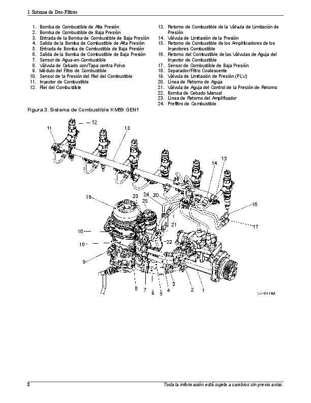
Priming the Fuel System – KM59 GEN1 – Two-Filter System..1358
Priming the Fuel System After Fuel Filter Change (Using J-47912 Priming Can) – Two-Filter System..1361
Priming the Fuel System After Fuel filter Change (Using Hand Primer on Fuel Filter Module) – Two-Filter System..1361
3.4 Fuel System Draining Procedure..1363
Draining the Fuel System Using J-48710 Prior to Repairs – Two-Filter System..1363
3.5 Fuel System Torque Specifications..1365
Fuel System Torque Specifications –Two Filter System..1365
3.6 Fuel Filter Module..1368
Description and Operation of the Fuel Filter Module and Related Parts –Two-Filter System..1368
Removal of the Fuel Filter Module – Two-Filter System..1370
Disassembly of the Fuel Filter Module – Two Filter System..1371
Assembly of the Fuel Filter Module – Two Filter System..1372
Installation of the Fuel Filter Module – Two Filter System..1372
Description and Operation of the Hand Primer- Two-Filter System..1373
Removal of the Hand Primer – Two-Filter System..1374
Inspection of the Hand Primer – Two- Filter System..1374
Installation of the Hand Primer – Two-Filter System..1375
3.7 Fuel Filters..1376
Description and Operation of the Fuel Prefilter – Two-Filter System..1376
Removal of the Fuel Prefilter – Two Filter System..1376
Installation of the Fuel Prefilter – Two Filter System..1377
Description and Operation of the Coalescer/Final Filter – Two-Filter System..1378
Removal of the Coalescer/Final Filter – Two Filter System..1379
Installation of the Coalescer/Final Filter – Two Filter System..1380
Removal of the Coalescer/Final Filter Stand Pipe – Two-Filter System..1382
Installation of the Coalescer/Final Filter Stand Pipe – Two-Filter System..1383
3.8 Water Drain Bowl..1384
Removal of the Water Drain Bowl – Two-Filter System..1384
Installation of the Water Drain Bowl – Two-Filter System..1384
3.9 Fuel Cooler..1385
Description and Operation of the Fuel Cooler – Two Filter System..1385
Removal of the Fuel Cooler – Two Filter System..1385
Inspection of the Fuel Cooler – Two-Filter System..1386
Installation of the Fuel Cooler – Two Filter System..1386
3.10 Fuel Cooler Delete Bypass Plate..1387
Description and Operation of the Fuel Cooler Delete Bypass Plate – Two Filter System..1387
Removal of the Fuel Cooler Delete Bypass Plate – Two Filter System..1387
Inspection of the Fuel Cooler Delete Bypass Plate – Two-Filter System..1388
Installation of the Fuel Cooler Delete Bypass Plate – Two Filter System..1388
3.11 Low Pressure Fuel Pump..1392
Description and Operation of the Low Pressure Fuel Pump and Related Parts – Two-Filter System..1392
Removal of the Low Pressure Fuel Pump – Two-Filter System..1393
Inspection of the Low Pressure Fuel Pump – Two-Filter System..1394
Installation of the Low Pressure Fuel Pump – Two-Filter System..1400
3.12 Low Pressure Fuel Pump Lines..1401
Description and Operation of Low Pressure Fuel Pump Lines – Two-Filter System..1401
Removal of the Low Pressure Fuel Pump Lines – Two-Filter System..1401
Inspection of the Low Pressure Fuel Pump Lines – Two-Filter System..1401
Installation of the Low Pressure Fuel Pump Lines – Two-Filter System..1402
3.13 Needle, Amplifier and Pressure Limiting Valve Return Lines..1404
Description and Operation of the Needle, Amplifier, and Pressure Limiting Valve Return Lines – Two-Filter System..1404
Removal of the Needle, Amplifier, and Pressure Limiting Valve (PLV) Return Lines – Two-Filter System..1405
Inspection of the Needle, Amplifier, Pressure Limiting Valve Return Lines – Two-Filter System..1406
Installation of the Needle, Amplifier, and Pressure Limiting Valve Return Lines – Two-Filter System..1407
3.14 Needle Return Pressure Control Valve..1409
Description and Operation of the Needle Control Pressure Valve – Two-Filter System..1409
Removal of the Needle Return Pressure Control Valve – Two-Filter System..1410
Inspection of the Needle Return Pressure Control Valve – Two-Filter System..1411
Installation of the Needle Return Pressure Control Valve – Two-Filter System..1413
3.15 HC Doser Fuel Supply Pressure Control Valve..1415
Description and Operation of the HC Doser Fuel Supply Pressure Control Valve – Two-Filter System..1415
Removal of the HC Doser Fuel Supply Pressure Control Valve – Two Filter System..1415
Inspection of the HC Doser Fuel Supply Pressure Control Valve – Two-Filter System..1416
Installation of the HC Doser Fuel Supply Pressure Control Valve – Two-Filter System..1418
3.16 Pressure Relief Valve..1420
Description and Operation of the Pressure Relief Valve – Two-Filter System..1420
Removal of the Pressure Relief Valve -Two-Filter System..1421
Inspection of the Pressure Relief Valve – Two-Filter System..1422
Installation of the Pressure Relief Valve – Two-Filter System..1428
3.17 High Pressure Fuel Pump..1430
Description and Operation of the High Pressure Fuel Pump and Related Parts – Two-Filter System..1430
Removal of the High Pressure Fuel Pump – Two-Filter System..1436
Inspection of the High Pressure Fuel Pump – Two-Filter System..1439
Installation of the High Pressure Fuel Pump – Two Filter System..1442
Removal of the High Pressure Fuel Pump Drive Gear -Two-Filter System..1445
Installation of the High Pressure Fuel Pump Drive Gear – Two-Filter System..1448
Checking Fuel Pump Timing – Two-Filter System..1453
Removal of the High Pressure Fuel Pump Camshaft Oil Seal – Two-Filter System..1459
Installation of the High Pressure Fuel Pump Camshaft Oil Seal – Two-Filter System..1463
Removal of the High Pressure Fuel Pump Locating Pin – Two-Filter System..1469
Installation of the High Pressure Fuel Pump Locating Pin -Two-Filter System..1472
3.18 High Pressure Fuel Flange..1475
Description and Operation of the High Pressure Fuel Flange – Two-Filter System..1475
Removal of the High Pressure Fuel Flange – Two-Filter System..1476
Inspection of the High Pressure Flange – Two-Filter System..1478
Installation of the High Pressure Fuel Flange – Two-Filter System..1481
3.19 Two Stage Valve..1484
Description and Operation of the Two Stage Valve – Two-Filter System..1484
Removal of the Two-Stage Valve for Two-Filter System..1484
Inspection of the Two-Stage Valve – Two- Filter System..1487
Installation of the Two-Stage Valve – Two Filter System..1493
3.20 Quantity Control Valve..1496
Description and Operation of the Quantity Control Valve – Two-Filter System..1496
Removal of the Quantity Control Valve – Two-Filter System..1497
Inspection of the Quantity Control Valve and High Pressure Pump Housing – Two-Filter System..1499
Installation of the Quantity Control Valve – Two-Filter System..1501
3.21 High Pressure Fuel Injector Lines..1503
Description and Operation of the High Pressure Fuel Injector Lines – Two-Filter System..1503
Removal of the High Pressure Fuel Injector Lines – Two-Filter System..1504
Inspection of the High Pressure Fuel Injector Lines- Two-Filter System..1508
Installation of the High Pressure Fuel Injector Lines – Two-Filter System..1509
3.22 High Pressure Fuel Rail Feed Lines..1515
Description and Operation of the High Pressure Fuel Rail Feed Lines and Related Parts – Two-Filter System..1515
Removal of the High Pressure Fuel Rail Feed Lines – Two-Filter System..1518
Inspection of the High Pressure Fuel Rail Feed Lines – Two Filter System..1521
Installation of the High Pressure Fuel Rail Feed Lines – Two-Filter System..1525
3.23 Fuel Rail..1537
Description and Operation of the Fuel Rail and Related Parts – Two-Filter System..1537
Removal of the Fuel Rail – Two-Filter System..1537
Inspection of the Fuel Rail – Two-Filter System..1539
Installation of the Fuel Rail – Two-Filter System..1539
3.24 Pressure Limiting Valve..1542
Description and Operation of the Pressure Limiting Valve – Two-Filter System..1542
Removal of the Pressure Limiting Valve – Two-Filter System..1542
Inspection of the Pressure Limiting Valve – Two-Filter System..1543
Installation of the Pressure Limiting Valve – Two-Filter System..1545
Resetting the Pressure Limiting Valve Counter – Two-Filter System..1546
3.25 Fuel Injector Wiring Harness..1548
Description and Operation of the Two-Piece Fuel Injector Wiring Harness – Two-Filter System..1548
Removal of the Two-Piece Fuel Injector Wiring Harness – Two-Filter System..1548
Inspection of the Two-Piece Fuel Injector Wiring Harness – Two-Filter System..1549
Installation of the Two-Piece Fuel Injector Wiring Harness – Two-Filter System..1549
3.26 Fuel Injectors..1552
Fuel Injection with Amplification – Two-Filter System..1552
Fuel Injection without Amplification – Two-Filter System..1553
Description and Operation of the Fuel Injector – Two-Filter System..1555
Removal of the Fuel Injector – Two-Filter System..1560
Installation of the Fuel Injector – Two-Filter System..1564
3.27 Fuel Injector Cup..1568
Description and Operation of the Fuel Injector Cup – Two-Filter System..1568
Removal of the Fuel Injector Cup – Two-Filter System..1568
Inspection of the Fuel Injector Cup – Two-Filter System..1569
Installation of the Fuel Injector Cup – Two-Filter System..1571
DDC-SVC-MAN-0082_2014 – EPA07_10_GHG14 DD Platform Fuel System Workshop Manual..1573
1 California Proposition 65 Warning and Engine Idle Notice..1576
2 Three-Filter System..1577
2.1 Fuel System Overview..1577
2.1.1 Fuel System Overview – Three-Filter System..1577
2.1.2 Amplified Pressure Common Rail System – Three-Filter System..1580
2.2 Fuel System Priming..1582
2.2.1 Priming the Fuel System Using ESOC 350 Fuel Priming Pump – Three-Filter System..1582
2.2.2 Priming the Fuel System After Fuel Filter Change (Using J-47912 Priming Can) – Three-Filter System..1583
2.2.3 Priming the Fuel System After Fuel filter Change (Using Hand Primer on Fuel Filter Module) – Three-Filter System..1583
2.2.4 Priming Port Pressures – Three-Filter System..1584
2.3 Fuel System Draining Procedure..1584
2.3.1 Draining the Fuel System Using J-48710 Prior to Repairs – Three-Filter System..1584
2.4 Fuel Filter Module..1585
2.4.1 Description and Operation of the Fuel Filter Module and Related Parts – Three-Filter System..1585
2.4.2 Removal of the Fuel Filter Module – Three-Filter System..1586
2.4.3 Disassembly of the Fuel Filter Module – Three-Filter System..1586
2.4.4 Assembly of the Fuel Filter Module – Three-Filter System..1587
2.4.5 Installation of the Fuel Filter Module – Three-Filter System..1587
2.5 Gallery Bypass Valve..1587
2.5.1 Description and Operation of the Gallery Bypass Valve – Three-Filter System..1587
2.5.2 Removal of the Gallery Bypass Valve – Three-Filter System..1588
2.5.3 Inspection of the Gallery Bypass Valve – Three-Filter System..1589
2.5.4 Installation of the Gallery Bypass Valve – Three-Filter System..1590
2.6 Fuel Filters..1591
2.6.1 Description and Operation of the Fuel Prefilter..1591
2.6.2 Removal of the Fuel Prefilter – Three-Filter System..1591
2.6.3 Removal of the Fuel Pre-Filter Stand Pipe – Three-Filter System..1592
2.6.4 Installation of the Fuel Prefilter – Three-Filter System..1592
2.6.5 Installation of the Fuel Pre-Filter Stand Pipe – Three-Filter System..1593
2.6.6 Description and Operation of the Water Separator/Coalescer – Three-Filter System..1594
2.6.7 Removal of the Water Separator/Coalescer – Three-Filter System..1595
2.6.8 Installation of the Water Separator/Coalescer – Three-Filter System..1596
2.6.9 Description and Operation of the Final Filter – Three-Filter System..1597
2.6.10 Removal of the Final Filter – Three-Filter System..1598
2.6.11 Installation of the Final Filter – Three-Filter System..1599
2.7 Water Drain Bowl..1600
2.7.1 Removal of the Water Drain Bowl – Three-Filter System..1600
2.7.2 Installation of The Water Drain Bowl – Three-Filter System..1602
2.7.3 Removal of the Water Drain Valve – Three-Filter System..1604
2.7.4 Installation of the Water Drain Valve – Three-Filter System..1606
2.8 Fuel Cooler..1609
2.8.1 Description and Operation of the Fuel Cooler – Three-Filter System..1609
2.8.2 Removal of the Fuel Cooler – Three-Filter System..1610
2.8.3 Installation of the Fuel Cooler – Three-Filter System..1610
2.9 Low Pressure Fuel Pump..1611
2.9.1 Description and Operation of the Low Pressure Fuel Pump and Related Parts – Three-Filter System..1611
2.9.2 Removal of the Low Pressure Fuel Pump – Three-Filter System..1612
2.9.3 Installation of the Low Pressure Fuel Pump – Three-Filter System..1612
2.10 Low Pressure Fuel Flange..1612
2.10.1 Description and Operation of the Low Pressure Fuel Flange – Three-Filter System..1612
2.10.2 Removal of the Low Pressure Fuel Flange – Three-Filter System..1613
2.10.3 Installation of the Low Pressure Fuel Flange – Three-Filter System..1613
2.11 Low Pressure Fuel Pump Lines..1613
2.11.1 Description and Operation of the V5 and V7 Low Pressure Fuel Pump Lines – Three-Filter System..1613
2.11.2 Removal of the Low Pressure Fuel Pump Lines – Three-Filter System..1615
2.11.3 Installation of the Low Pressure Fuel Pump Lines – Three-Filter System..1615
2.12 Needle, Amplifier, and Pressure Limiting Valve Return Lines..1616
2.12.1 Description and Operation of the Needle, Amplifier, and Pressure Limiting Valve Return Lines – Three-Filter System..1616
2.12.2 Removal of the Needle, Amplifier, and Pressure Limiting Valve Return Lines – Three-Filter System..1616
2.12.3 Installation of the Needle, Amplifier, and Pressure Limiting Valve Return Lines – Three-Filter System..1617
2.13 Needle Return Pressure Control Valve..1618
2.13.1 Removal of the Needle Return Pressure Control Valve – Three-Filter System..1618
2.13.2 Inspection of the Needle Return Pressure Control Valve – Three-Filter System..1618
2.13.3 Installation of the Needle Return Pressure Control Valve – Three-Filter System..1619
2.14 HC Doser Fuel Supply Pressure Control Valve..1621
2.14.1 Description and Operation of the Hydrocarbon Doser Supply Pressure Control Valve – Three-Filter System..1621
2.14.2 Removal of the HC Doser Fuel Supply Pressure Control Valve – Three-Filter System..1621
2.14.3 Installation of the HC Doser Fuel Supply Pressure Control Valve – Three-Filter System..1621
2.15 Pressure Relief Valve..1622
2.15.1 Description and Operation of the Pressure Relief Valve – Three-Filter System..1622
2.15.2 Removal of the Pressure Relief Valve – Three-Filter System..1622
2.15.3 Inspection of the Pressure Relief Valve and High Pressure Pump Housing – Three-Filter System..1623
2.15.4 Installation of the Pressure Relief Valve – Three-Filter System..1624
2.16 High Pressure Fuel Pump..1625
2.16.1 Description and Operation of the High Pressure Fuel Pump and Related Parts – Three-Filter System..1625
2.16.2 Removal of the High Pressure Fuel Pump – Three-Filter System..1627
2.16.3 Installation of the High Pressure Fuel Pump – Three-Filter System..1628
2.16.4 Checking Fuel Pump Timing – Three-Filter System..1630
2.16.5 Removal of the High Pressure Fuel Pump Drive Gear – Three-Filter System..1633
2.16.6 Installation of the High Pressure Fuel Pump Drive Gear – Three-Filter System..1634
2.16.7 Removal of the High Pressure Fuel Pump Locating Pin – Three-Filter System..1639
2.16.8 Installation of the High Pressure Fuel Pump Locating Pin – Three-Filter System..1641
2.17 High Pressure Fuel Flange..1643
2.17.1 Description and Operation of the High Pressure Fuel Flange – Three-Filter System..1643
2.17.2 Removal of the High Pressure Fuel Flange – Three-Filter System..1644
2.17.3 Installation of the High Pressure Fuel Flange – Three-Filter System..1644
2.18 Two Stage Valve..1644
2.18.1 Description and Operation of the Two Stage Valve – Three-Filter System..1644
2.18.2 Removal of the Two-Stage Valve – Three-Filter System..1645
2.18.3 Inspection of the Two-Stage Valve and High Pressure Pump Housing – Three-Filter System..1646
2.18.4 Installation of the Two-Stage Valve – Three-Filter System..1648
2.19 Quantity Control Valve..1649
2.19.1 Description and Operation of the Quantity Control Valve – Three-Filter System..1650
2.19.2 Removal of the Quantity Control Valve – Three-Filter System..1650
2.19.3 Inspection of the Quantity Control Valve and High Pressure Pump Housing – Three-Filter System..1651
2.19.4 Installation of the Quantity Control Valve – Three-Filter System..1652
2.19.5 EPA07 Resetting Quantity Control Valve Adaptive Values – Three-Filter System..1653
2.19.6 EPA10 Resetting Quantity Control Valve Adaptive Values – Three-Filter System..1654
2.20 High Pressure Fuel Injector Lines..1655
2.20.1 Description and Operation of the High Pressure Fuel Injector Lines – Three-Filter System..1655
2.20.2 Removal of the High Pressure Fuel Injector Lines – Three-Filter System..1656
2.20.3 Installation of the High Pressure Fuel Injector Lines – Three-Filter System..1658
2.21 High Pressure Fuel Rail Feed Lines..1661
2.21.1 Removal of the High Pressure Fuel Rail Feed Lines – Three-Filter System..1661
2.21.2 Inspection of the High Pressure Fuel Rail Feed Lines – Three-Filter System..1662
2.21.3 Installation of the DD13 High Pressure Fuel Rail Feed Lines – Three-Filter System..1664
2.21.4 Installation of the DD15 and DD16 High Pressure Fuel Rail Feed Lines – Three-Filter System..1667
2.22 Fuel Rail..1670
2.22.1 Description and Operation of the Fuel Rail and Related Parts – Three-Filter System..1670
2.22.2 Removal of the Fuel Rail – Three-Filter System..1671
2.22.3 Inspection of the Fuel Rail – Three-Filter System..1672
2.22.4 Installation of the Fuel Rail – Three-Filter System..1672
2.23 Pressure Limiting Valve..1673
2.23.1 Description and Operation of the Pressure Limiting Valve – Three-Filter System..1673
2.23.2 Removal of the Pressure Limiting Valve – Three-Filter System..1674
2.23.3 Installation of the Pressure Limiting Valve – Three-Filter System..1674
2.23.4 Resetting the Pressure Limiting Valve Counter – Three-Filter System..1675
2.24 Fuel Injector Wiring Harness..1675
2.24.1 Description and Operation of the Two-Piece Fuel Injector Wiring Harness – Three-Filter System..1676
2.24.2 Removal of the Two-Piece Fuel Injector Wiring Harness – Three-Filter System..1676
2.24.3 Inspection of the Two-Piece Fuel Injector Wiring Harness – Three-Filter System..1676
2.24.4 Installation of the Two-Piece Fuel Injector Wiring Harness – Three-Filter System..1677
2.24.5 Description and Operation of the One-Piece Fuel Injector Wiring Harness – Three-Filter System..1677
2.24.6 Removal of the One-Piece Fuel Injector Wiring Harness – Three-Filter System..1678
2.24.7 Inspection of the One-Piece Fuel Injector Wiring Harness – Three-Filter System..1678
2.24.8 Installation of the One-Piece Fuel Injector Wiring Harness – Three-Filter System..1679
2.25 Fuel Injectors..1679
2.25.1 Fuel Injection with Amplification – Three-Filter System..1679
2.25.2 Fuel Injection without Amplification – Three-Filter System..1681
2.25.3 Description and Operation of the Fuel Injector – Three-Filter System..1681
2.25.4 Removal of the Fuel Injector – Three-Filter System..1684
2.25.5 Installation of the Fuel Injector – Three-Filter System..1685
2.25.6 Threshold Resetting and Learning – Three-Filter System..1688
2.26 Fuel Injector Cup..1690
2.26.1 Description and Operation of the Fuel Injector Cup – Three-Filter System..1690
2.26.2 Removal of the Fuel Injector Cup – Three-Filter System..1690
2.26.3 Installation of the Fuel Injector Cup – Three-Filter System..1691
3 Two-Filter System..1692
3.1 Fuel System Overview..1692
3.1.1 Fuel System (With MCM Heat Exchanger) –Two-Filter System..1692
3.1.2 Fuel System (Without MCM Heat Exchanger) –Two-Filter System..1693
3.1.3 Operation of the Fuel System..1695
3.2 Amplified Pressure Common Rail System..1696
3.2.1 Fuel System -Two-Filter System..1696
3.3 Fuel System Priming..1697
3.3.1 Priming the Fuel System Using ESOC 350 Fuel Priming Pump – Two-Filter System..1697
3.3.2 Priming the Fuel System After Fuel Filter Change (Using J-47912 Priming Can) – Two-Filter System..1698
3.3.3 Priming the Fuel System After Fuel filter Change (Using Hand Primer on Fuel Filter Module) – Two-Filter System..1698
3.3.4 Normal Fuel System Pressures- Two-Filter System..1699
3.4 Fuel System Draining Procedure..1700
3.4.1 Draining the Fuel System Using J-48710 Prior to Repairs – Two-Filter System..1700
3.5 Fuel System Torque Specifications..1701
3.5.1 Fuel System Torque Specifications –Two Filter System..1701
3.6 Fuel Filter Module..1702
3.6.1 Description and Operation of the Fuel Filter Module and Related Parts –Two-Filter System..1702
3.6.2 Removal of the Fuel Filter Module – Two-Filter System..1704
3.6.3 Disassembly of the Fuel Filter Module – Two Filter System..1705
3.6.4 Assembly of the Fuel Filter Module – Two Filter System..1705
3.6.5 Installation of the Fuel Filter Module – Two Filter System..1706
3.6.6 Description and Operation of the Hand Primer- Two-Filter System..1706
3.6.7 Removal of the Hand Primer – Two-Filter System..1707
3.6.8 Inspection of the Hand Primer – Two- Filter System..1707
3.6.9 Installation of the Hand Primer – Two-Filter System..1708
3.6.10 Description and Operation of the Fuel Filter Module Housing Half – Two-Filter System..1708
3.6.11 Removal of the Fuel Filter Module Housing Half – Two-Filter System..1709
3.6.12 Inspection of the Fuel Filter Module Housing Half – Two-Filter System..1710
3.6.13 Installation of the Fuel Filter Module Housing Half – Two-Filter System..1712
3.7 Gallery Bypass Valve..1715
3.7.1 Description and Operation of the Gallery Bypass Valve – Two-Filter System..1715
3.7.2 Removal of the Gallery Bypass Valve – Two-Filter System..1716
3.7.3 Installation of the Gallery Bypass Valve – Two-Filter System..1717
3.8 Fuel Filters..1719
3.8.1 Description and Operation of the Fuel Prefilter – Two-Filter System..1719
3.8.2 Removal of the Fuel Prefilter – Two Filter System..1720
3.8.3 Installation of the Fuel Prefilter – Two Filter System..1721
3.8.4 Description and Operation of the Coalescer/Final Filter – Two-Filter System..1722
3.8.5 Removal of the Coalescer/Final Filter – Two Filter System..1724
3.8.6 Installation of the Coalescer/Final Filter – Two Filter System..1724
3.8.7 Removal of the Coalescer/Final Filter Stand Pipe – Two-Filter System..1726
3.8.8 Installation of the Coalescer/Final Filter Stand Pipe – Two-Filter System..1726
3.9 Water Drain Bowl..1727
3.9.1 Removal of the Water Drain Bowl – Two-Filter System..1727
3.9.2 Installation of the Water Drain Bowl – Two-Filter System..1727
3.10 Fuel Cooler..1728
3.10.1 Description and Operation of the Fuel Cooler – Two Filter System..1728
3.10.2 Removal of the Fuel Cooler – Two Filter System..1729
3.10.3 Inspection of the Fuel Cooler – Two-Filter System..1729
3.10.4 Installation of the Fuel Cooler – Two Filter System..1729
3.11 Low Pressure Fuel Pump..1730
3.11.1 Description and Operation of the Low Pressure Fuel Pump and Related Parts – Two-Filter System..1730
3.11.2 Removal of the Low Pressure Fuel Pump – Two-Filter System..1731
3.11.3 Inspection of the Low Pressure Fuel Pump – Two-Filter System..1732
3.11.4 Installation of the Low Pressure Fuel Pump – Two-Filter System..1736
3.12 Low Pressure Fuel Pump Lines..1736
3.12.1 Description and Operation of Low Pressure Fuel Pump Lines – Two-Filter System..1736
3.12.2 Removal of the Low Pressure Fuel Pump Lines – Two-Filter System..1738
3.12.3 Inspection of the Low Pressure Fuel Pump Lines – Two-Filter System..1738
3.12.4 Installation of the Low Pressure Fuel Pump Lines – Two-Filter System..1739
3.13 Needle, Amplifier and Pressure Limiting Valve Return Lines..1740
3.13.1 Description and Operation of the Needle, Amplifier, and Pressure Limiting Valve Return Lines – Two-Filter System..1740
3.13.2 Removal of the Needle, Amplifier, and Pressure Limiting Valve (PLV) Return Lines – Two-Filter System..1741
3.13.3 Inspection of the Needle, Amplifier, Pressure Limiting Valve Return Lines – Two-Filter System..1742
3.13.4 Installation of the Needle, Amplifier, and Pressure Limiting Valve (PLV) Return Lines – Two-Filter System..1743
3.14 Needle Return Pressure Control Valve..1744
3.14.1 Description and Operation of the Needle Control Pressure Valve – Two-Filter System..1744
3.14.2 Removal of the Needle Return Pressure Control Valve – Two-Filter System..1745
3.14.3 Inspection of the Needle Return Pressure Control Valve – Two-Filter System..1746
3.14.4 Installation of the Needle Return Pressure Control Valve – Two-Filter System..1748
3.15 HC Doser Fuel Supply Pressure Control Valve..1749
3.15.1 Description and Operation of the HC Doser Fuel Supply Pressure Control Valve – Two-Filter System..1749
3.15.2 Removal of the HC Doser Fuel Supply Pressure Control Valve – Two Filter System..1750
3.15.3 Inspection of the HC Doser Fuel Supply Pressure Control Valve – Two-Filter System..1751
3.15.4 Installation of the HC Doser Fuel Supply Pressure Control Valve – Two-Filter System..1752
3.16 Pressure Relief Valve..1753
3.16.1 Description and Operation of the Pressure Relief Valve – Two-Filter System..1753
3.16.2 Removal of the Pressure Relief Valve -Two-Filter System..1754
3.16.3 Inspection of the Pressure Relief Valve – Two-Filter System..1756
3.16.4 Installation of the Pressure Relief Valve – Two-Filter System..1760
3.17 High Pressure Fuel Pump..1761
3.17.1 Description and Operation of the High Pressure Fuel Pump and Related Parts – Two-Filter System..1761
3.17.2 Removal of the High Pressure Fuel Pump – Two-Filter System..1764
3.17.3 Inspection of the High Pressure Fuel Pump – Two-Filter System..1766
3.17.4 Installation of the High Pressure Fuel Pump – Two Filter System..1768
3.17.5 Removal of the High Pressure Fuel Pump Drive Gear -Two-Filter System..1770
3.17.6 Installation of the High Pressure Fuel Pump Drive Gear – Two-Filter System..1773
3.17.7 Checking Fuel Pump Timing – Two-Filter System..1776
3.17.8 Removal of the High Pressure Fuel Pump Locating Pin – Two-Filter System..1779
3.17.9 Installation of the High Pressure Fuel Pump Locating Pin -Two-Filter System..1781
3.18 High Pressure Fuel Flange..1783
3.18.1 Description and Operation of the High Pressure Fuel Flange – Two-Filter System..1783
3.18.2 Removal of the High Pressure Fuel Flange – Two-Filter System..1785
3.18.3 Inspection of the High Pressure Flange – Two-Filter System..1786
3.18.4 Installation of the High Pressure Fuel Flange – Two-Filter System..1788
3.19 Two Stage Valve..1790
3.19.1 Description and Operation of the Two Stage Valve – Two-Filter System..1790
3.19.2 Removal of the Two-Stage Valve for Two-Filter System..1791
3.19.3 Inspection of the Two-Stage Valve – Two- Filter System..1792
3.19.4 Installation of the Two-Stage Valve – Two Filter System..1796
3.20 Quantity Control Valve..1798
3.20.1 Description and Operation of the Quantity Control Valve – Two-Filter System..1798
3.20.2 Removal of the Quantity Control Valve – Two-Filter System..1798
3.20.3 Inspection of the Quantity Control Valve and High Pressure Pump Housing – Two-Filter System..1799
3.20.4 Installation of the Quantity Control Valve – Two-Filter System..1800
3.20.5 Resetting Quantity Control Valve Adaptive Values – Two-Filter System..1801
3.21 High Pressure Fuel Injector Lines..1802
3.21.1 Description and Operation of the High Pressure Fuel Injector Lines – Two-Filter System..1802
3.21.2 Removal of the High Pressure Fuel Injector Lines – Two-Filter System..1804
3.21.3 Inspection of the High Pressure Fuel Injector Lines- Two-Filter System..1806
3.21.4 Installation of the High Pressure Fuel Injector Lines – Two-Filter System..1807
3.22 High Pressure Fuel Rail Feed Lines..1809
3.22.1 Description and Operation of the High Pressure Fuel Rail Feed Lines and Related Parts – Two-Filter System..1809
3.22.2 Removal of the High Pressure Fuel Rail Feed Lines – Two-Filter System..1811
3.22.3 Inspection of the High Pressure Fuel Rail Feed Lines – Two Filter System..1811
3.22.4 Installation of the High Pressure Fuel Rail Feed Lines – Two-Filter System..1812
3.23 Fuel Rail..1816
3.23.1 Description and Operation of the Fuel Rail and Related Parts – Two-Filter System..1816
3.23.2 Removal of the Fuel Rail – Two-Filter System..1817
3.23.3 Inspection of the Fuel Rail – Two-Filter System..1819
3.23.4 Installation of the Fuel Rail – Two-Filter System..1819
3.24 Pressure Limiting Valve..1821
3.24.1 Description and Operation of the Pressure Limiting Valve – Two-Filter System..1821
3.24.2 Removal of the Pressure Limiting Valve – Two-Filter System..1822
3.24.3 Inspection of the Pressure Limiting Valve – Two-Filter System..1822
3.24.4 Installation of the Pressure Limiting Valve – Two-Filter System..1824
3.24.5 Resetting the Pressure Limiting Valve Counter – Two-Filter System..1824
3.25 Fuel Injector Wiring Harness..1825
3.25.1 Description and Operation of the Two-Piece Fuel Injector Wiring Harness – Two-Filter System..1825
3.25.2 Removal of the Two-Piece Fuel Injector Wiring Harness – Two-Filter System..1826
3.25.3 Inspection of the Two-Piece Fuel Injector Wiring Harness – Two-Filter System..1826
3.25.4 Installation of the Two-Piece Fuel Injector Wiring Harness – Two-Filter System..1826
3.26 Fuel Injectors..1827
3.26.1 Fuel Injection with Amplification – Two-Filter System..1827
3.26.2 Fuel Injection without Amplification – Two-Filter System..1829
3.26.3 Description and Operation of the Fuel Injector – Two-Filter System..1829
3.26.4 Removal of the Fuel Injector – Two-Filter System..1832
3.26.5 Installation of the Fuel Injector – Two-Filter System..1833
3.26.6 Threshold Resetting and Learning – Two-Filter System..1836
3.27 Fuel Injector Cup..1840
3.27.1 Description and Operation of the Fuel Injector Cup – Two-Filter System..1840
3.27.2 Removal of the Fuel Injector Cup – Two-Filter System..1841
3.27.3 Inspection of the Fuel Injector Cup – Two-Filter System..1841
3.27.4 Installation of the Fuel Injector Cup – Two-Filter System..1842
DDC-SVC-MAN-0083 – EPA07 10 GHG14 Exhaust – EGR – ATS Manual (10.1 Description and Operation of DD13 Exhaust Gas Recirculation Cooler Water Manifold Assembly)..1844
DD13 Exhaust Gas Recirculation Cooler Water Manifold Assembly..1844
10.1 Description and Operation of DD13 Exhaust Gas Recirculation Cooler Water Manifold Assembly..1844
10.2 Removal of the DD13 Exhaust Gas Recirculation Cooler Water Manifold Assembly..1847
10.3 Inspection of the DD13 EGR Cooler Water Manifold Assembly..1849
10.4 Testing of the DD13 Exhaust Gas Recirculation Cooler Water Manifold Assembly – In Chassis..1850
10.5 Installation of the DD13 EGR Cooler Water Manifold Assembly..1852
DDC-SVC-MAN-0083 – EPA07 10 GHG14 Exhaust – EGR – ATS Manual (11.1 Description and Operation of the DD15 and DD16 Exhaust Gas Recirculation Cooler)..1854
DD15 and DD16 Exhaust Gas Recirculation Cooler..1854
11.1 Description and Operation of the DD15 and DD16 Exhaust Gas Recirculation Cooler..1854
11.2 Removal of the DD15 and DD16 Exhaust Gas Recirculation Cooler..1858
11.3 Testing of the DD15 and DD16 Exhaust Gas Recirculation Cooler – In Chassis..1859
11.4 Installation of the DD15 and DD16 Exhaust Gas Recirculation Cooler..1861
DDC-SVC-MAN-0083 – EPA07 10 GHG14 Exhaust – EGR – ATS Manual (12.1 Removal of the Exhaust Gas Recirculation Valve Actuator Pull Rod)..1863
DD13 Exhaust Gas Recirculation Valve Actuator Pull Rod..1863
12.1 Removal of the Exhaust Gas Recirculation Valve Actuator Pull Rod..1863
12.2 Inspection of DD13 Exhaust Gas Recirculation Valve Actuator Pull Rod..1865
12.3 Installation of the DD13 Exhaust Gas Recirculation Valve Actuator Pull Rod..1866
DDC-SVC-MAN-0083 – EPA07 10 GHG14 Exhaust – EGR – ATS Manual (13.1 Removal of the DD15 and DD16 Exhaust Gas Recirculation Valve Actuator Pull Rod)..1868
DD15 and DD16 Exhaust Gas Recirculation Valve Actuator Pull Rod..1868
13.1 Removal of the DD15 and DD16 Exhaust Gas Recirculation Valve Actuator Pull Rod..1868
13.2 Installation of the DD15 and DD16 Exhaust Gas Recirculation Valve Actuator Pull Rod..1871
DDC-SVC-MAN-0083 – EPA07 10 GHG14 Exhaust – EGR – ATS Manual (14.1 Removal of the GHG14 DD15 AT Exhaust Gas Recirculation Valve Actuator Pull Rod)..1873
GHG14 DD15 AT Exhaust Gas Recirculation Actuator Pull Rod..1873
14.1 Removal of the GHG14 DD15 AT Exhaust Gas Recirculation Valve Actuator Pull Rod..1873
14.2 Inspection of the GHG14 DD15 AT Exhaust Gas Recirculation Valve Actuator Pull Rod..1875
14.3 Installation of the GHG14 DD15 AT Exhaust Gas Recirculation Valve Actuator Pull Rod..1876
DDC-SVC-MAN-0083 – EPA07 10 GHG14 Exhaust – EGR – ATS Manual (15.1 Description and Operation of the DD13 Exhaust Gas Recirculation Valve Actuator)..1878
DD13 Exhaust Gas Recirculation Valve Actuator..1878
15.1 Description and Operation of the DD13 Exhaust Gas Recirculation Valve Actuator..1878
15.2 Removal of the DD13 Exhaust Gas Recirculation Valve Actuator..1881
15.3 Installation of the DD13 Exhaust Gas Recirculation Valve Actuator..1882
DDC-SVC-MAN-0083 – EPA07 10 GHG14 Exhaust – EGR – ATS Manual (16.1 Description and Operation of the DD15 and DD16 Exhaust Gas Recirculation Valve Actuator)..1884
DD15 and DD16 Exhaust Gas Recirculation Valve Actuator..1884
16.1 Description and Operation of the DD15 and DD16 Exhaust Gas Recirculation Valve Actuator..1884
16.2 Removal of the DD15 and DD16 Delphi© Exhaust Gas Recirculation Valve Actuator..1888
16.3 Installation of the DD15 and DD16 Delphi© Exhaust Gas Recirculation Valve Actuator..1890
16.4 Removal of the DD15 and DD16 Sonceboz® Exhaust Gas Recirculation Valve Actuator..1892
16.5 Installation of the DD15 and DD16 Sonceboz® Exhaust Gas Recirculation Valve Actuator..1895
DDC-SVC-MAN-0083 – EPA07 10 GHG14 Exhaust – EGR – ATS Manual (17.1 Description and Operation of the GHG14 DD15 AT Exhaust Gas Recirculation Valve Actuator)..1898
GHG14 DD15 AT Exhaust Gas Recirculation Valve Actuator..1898
17.1 Description and Operation of the GHG14 DD15 AT Exhaust Gas Recirculation Valve Actuator..1898
17.2 Removal of the GHG14 DD15 AT Exhaust Gas Recirculation Valve Actuator..1899
17.3 Installation of the GHG14 DD15 AT Exhaust Gas Recirculation Valve Actuator..1901
DDC-SVC-MAN-0083 – EPA07 10 GHG14 Exhaust – EGR – ATS Manual (18.1 Removal of the Exhaust Gas Recirculation Actuato Lever)..1906
Exhaust Gas Recirculation Actuator Lever..1906
18.1 Removal of the Exhaust Gas Recirculation Actuator Lever..1906
18.2 Installation of the Exhaust Gas Recirculation Actuator Lever..1908
DDC-SVC-MAN-0083 – EPA07 10 GHG14 Exhaust – EGR – ATS Manual (19.1 Description and Operation of the GHG14 DD15 AT Exhaust Gas Recirculation Valve_Hot Pipe)..1912
GHG14 DD15 AT Exhaust Gas Recirculation Valve/Hot Pipe..1912
19.1 Description and Operation of the GHG14 DD15 AT Exhaust Gas Recirculation Valve/Hot Pipe..1912
19.2 Removal of the GHG14 DD15 AT Exhaust Gas Recirculation Valve/Hot Pipe..1913
19.3 Installation of the GHG14 DD15 AT Exhaust Gas Recirculation Valve/Hot Pipe..1915
DDC-SVC-MAN-0083 – EPA07 10 GHG14 Exhaust – EGR – ATS Manual (2.1 Description and Operation of the Exhaust Manifold and Related Parts)..1917
47.1 Description and Operation of the GHG14 Diesel Exhaust Fluid Dosing Unit..1917
47.2 Removal of the GHG14 Dosing System Doser..1918
47.3 Installation of the GHG14 Dosing System Doser..1919
47.4 Removal of the GHG14 Diesel Exhaust Fluid Dosing Unit Inlet Screen..1921
47.5 Installation of the GHG14 Diesel Exhaust Fluid Dosing Unit Inlet Screen..1922
GHG14 Diesel Exhaust Fluid Dosing System..1923
47.1 Description and Operation of the GHG14 Diesel Exhaust Fluid Dosing Unit..1923
47.2 Removal of the GHG14 Dosing System Doser..1924
47.3 Installation of the GHG14 Dosing System Doser..1925
47.4 Removal of the GHG14 Diesel Exhaust Fluid Dosing Unit Inlet Screen..1927
47.5 Installation of the GHG14 Diesel Exhaust Fluid Dosing Unit Inlet Screen..1928
DDC-SVC-MAN-0083 – EPA07 10 GHG14 Exhaust – EGR – ATS Manual (20.1 Description and Operation of the GHG14 DD15 AT Flanged Exhaust Manifold and Related Parts)..1929
GHG14 DD15 AT Flanged Exhaust Manifold..1929
20.1 Description and Operation of the GHG14 DD15 AT Flanged Exhaust Manifold and Related Parts..1929
20.2 Removal of the GHG14 DD15 AT Flanged Exhaust Manifold..1930
20.3 Installation of the GHG14 DD15 AT Flanged Exhaust Manifold..1932
DDC-SVC-MAN-0083 – EPA07 10 GHG14 Exhaust – EGR – ATS Manual (21.1 Description and Operation of the DD13 Exhaust Gas Recirculation Valve)..1935
21.1 Description and Operation of the DD13 Exhaust Gas Recirculation Valve..1935
DD13 Exhaust Gas Recirculation Valve..1936
DDC-SVC-MAN-0083 – EPA07 10 GHG14 Exhaust – EGR – ATS Manual (22.1 Description and Operation of the DD15 and DD16 Exhaust Gas Recirculation Valve)..1937
DD15 and DD16 Exhaust Gas Recirculation Valve..1937
22.1 Description and Operation of the DD15 and DD16 Exhaust Gas Recirculation Valve..1937
22.2 Removal of the DD15 and DD16 Exhaust Gas Recirculation Valve..1940
22.3 Installation of the DD15 and DD16 Exhaust Gas Recirculation Valve..1941
DDC-SVC-MAN-0083 – EPA07 10 GHG14 Exhaust – EGR – ATS Manual (23.1 Description and Operation of the Mixer Pipe)..1942
Mixer Pipe..1942
23.1 Description and Operation of the Mixer Pipe..1942
23.2 Removal of the Mixer Pipe..1943
23.3 Inspection of the Mixer Pipe..1944
23.4 Installation of the Mixer Pipe..1945
DDC-SVC-MAN-0083 – EPA07 10 GHG14 Exhaust – EGR – ATS Manual (24.1 Removal of the Hydrocarbon Doser Block Feed Line)..1946
Hydrocarbon Doser Block Feed Line..1946
24.1 Removal of the Hydrocarbon Doser Block Feed Line..1946
24.2 Installation of the Hydrocarbon Doser Block Feed Line..1947
DDC-SVC-MAN-0083 – EPA07 10 GHG14 Exhaust – EGR – ATS Manual (25.1 Removal of the Hydrocarbon Doser Coolant Lines – DD13 and DD15AT)..1948
Hydrocarbon Doser Coolant Lines..1948
25.1 Removal of the Hydrocarbon Doser Coolant Lines – DD13 and DD15AT..1948
25.2 Installation of the Hydrocarbon Doser Coolant Lines – DD13 and DD15AT..1950
25.3 Removal of the Hydrocarbon Doser Coolant Lines – DD15TC and DD16..1952
25.4 Installation of the Hydrocarbon Doser Coolant Lines – DD15TC and DD16..1954
DDC-SVC-MAN-0083 – EPA07 10 GHG14 Exhaust – EGR – ATS Manual (26.1 Description and Operation of the Hydrocarbon Doser Block)..1956
Hydrocarbon Doser Block..1956
26.1 Description and Operation of the Hydrocarbon Doser Block..1956
26.2 Removal of the Hydrocarbon Doser Block..1958
26.3 Installation of the Hydrocarbon Doser Block..1962
DDC-SVC-MAN-0083 – EPA07 10 GHG14 Exhaust – EGR – ATS Manual (27.1 Description and Operation of the Fuel Doser Injector Valve)..1965
Fuel Doser Injector Valve..1965
27.1 Description and Operation of the Fuel Doser Injector Valve..1965
27.2 Removal of the Hydrocarbon Doser Fuel Injector Valve..1967
27.3 Installation of the Hydrocarbon Doser Fuel Injector Valve..1970
DDC-SVC-MAN-0083 – EPA07 10 GHG14 Exhaust – EGR – ATS Manual (28.1 Removal of the Hydrocarbon Fuel Doser Housing)..1974
Hydrocarbon Fuel Doser Housing..1974
28.1 Removal of the Hydrocarbon Fuel Doser Housing..1974
28.2 Installation of the Hydrocarbon Fuel Doser Housing..1978
DDC-SVC-MAN-0083 – EPA07 10 GHG14 Exhaust – EGR – ATS Manual (29.1 Removal of the Fuel Compensation Pressure Sensor)..1983
Fuel Compensation Pressure Sensor..1983
29.1 Removal of the Fuel Compensation Pressure Sensor..1983
29.2 Installation of the Fuel Compensation Pressure Sensor..1985
DDC-SVC-MAN-0083 – EPA07 10 GHG14 Exhaust – EGR – ATS Manual (3.1 Description and Operation of the DD13 Exhaust Flanged Manifold)..1987
DD13 Exhaust Flanged Manifold..1987
3.1 Description and Operation of the DD13 Exhaust Flanged Manifold..1987
3.2 Removal of the DD13 Exhaust Flanged Manifold..1989
3.3 Installation of the DD13 Exhaust Flanged Manifold..1991
DDC-SVC-MAN-0083 – EPA07 10 GHG14 Exhaust – EGR – ATS Manual (30.1 Description and Operation of Intake Throttle Valve and Adaptor)..1993
Intake Throttle Valve and Adaptor..1993
30.1 Description and Operation of Intake Throttle Valve and Adaptor..1993
30.2 Removal of the Intake Throttle Valve and Adaptor..1995
30.3 Installation of the Intake Throttle Valve and Adaptor..1996
DDC-SVC-MAN-0083 – EPA07 10 GHG14 Exhaust – EGR – ATS Manual (31.1 Overview of EPA07 Aftertreatment System)..1997
EPA07 Aftertreatment System Overview..1997
31.1 Overview of EPA07 Aftertreatment System..1997
31.2 Description and Operation of the EPA07 Aftertreatment Device..1998
31.3 Description and Operation of the Diesel Particulate Filter..2000
31.4 EPA07 Aftertreatment Operating Requirements..2001
31.5 EPA07 Aftertreatment System Component Overview..2002
31.6 EPA07 Aftertreatment Regeneration Strategy..2004
EPA07 DD15 Regeneration Strategy..2004
EPA07 DD15 Idle Timing..2004
Passive Regeneration..2005
Active Regeneration..2005
Parked Regeneration..2006
31.7 Performing a Parked Regeneration – EPA07..2008
31.8 Unable to Perform a Parked Regeneration – EPA07..2010
31.9 Instrument Panel Lamps..2012
Amber Warning Lamp..2012
Red Stop Lamp..2012
Diesel Particulate Filter Regeneration Lamp..2012
High Exhaust System Temperature Lamp..2013
Malfunction Indicator Lamp..2013
DDC-SVC-MAN-0083 – EPA07 10 GHG14 Exhaust – EGR – ATS Manual (32.1 Description and Operation of the EPA07 Aftertreatment Device Temperature Sensors)..2014
EPA07 Aftertreatment Device Sensors..2014
32.1 Description and Operation of the EPA07 Aftertreatment Device Temperature Sensors..2014
32.2 Removal of the EPA07 Temperature Sensors..2015
32.3 Installation of the EPA07 Temperature Sensors..2016
32.4 Removal of the EPA07 Pressure Sensors..2017
32.5 Installation of the EPA07 Pressure Sensors..2018
DDC-SVC-MAN-0083 – EPA07 10 GHG14 Exhaust – EGR – ATS Manual (33.2 Requirements – EPA07)..2019
33.2 Requirements – EPA07..2019
Service Record..2019
EPA07 Aftertreatment Device Cleaning and Maintenance..2020
33.1 Accumulated Ash – EPA07..2020
33.2 EPA07 Diesel Particulate Filter Ash Measurement Procedure..2021
33.3 Requirements – EPA07..2026
Service Record..2026
DDC-SVC-MAN-0083 – EPA07 10 GHG14 Exhaust – EGR – ATS Manual (34.1 Removal of the EPA07 Aftertreatment Device from the Vehicle)..2027
34.1 Removal of the EPA07 Aftertreatment Device from the Vehicle..2027
34.2 Installation of the EPA07 Aftertreatment Device..2033
EPA07 Aftertreatment Device Removal and Installation on Vehicle..2035
34.1 Removal of the EPA07 Aftertreatment Device from the Vehicle..2035
34.2 Installation of the EPA07 Aftertreatment Device..2041
DDC-SVC-MAN-0083 – EPA07 10 GHG14 Exhaust – EGR – ATS Manual (35.1 Disassembly of the EPA07 Aftertreatment Device)..2043
35.1 Disassembly of the EPA07 Aftertreatment Device..2043
35.2 Preliminary Inspection of the Aftertreatment Device..2046
35.3 Diesel Oxidation Catalyst (DOC) Inspection – All Years..2047
35.4 Diesel Particulate Filter (DPF) Inspection – All Years..2050
35.5 Outlet Flange Adapter Inspection – All Years..2057
35.6 Assembly of the EPA07 Aftertreatment Device..2059
Disassembly and Inspection of the Aftertreatment Device..2060
35.1 Disassembly of the EPA07 Aftertreatment Device..2060
35.2 Preliminary Inspection of the Aftertreatment Device..2063
35.3 Diesel Oxidation Catalyst (DOC) Inspection – All Years..2064
35.4 Diesel Particulate Filter (DPF) Inspection – All Years..2067
35.5 Outlet Flange Adapter Inspection – All Years..2074
35.6 Assembly of the EPA07 Aftertreatment Device..2076
DDC-SVC-MAN-0083 – EPA07 10 GHG14 Exhaust – EGR – ATS Manual (36.1 Resetting the EPA07 Diesel Particulate Filter Ash Accumulators)..2077
36.1 Resetting the EPA07 Diesel Particulate Filter Ash Accumulators..2077
36.2 Resetting the EPA10/GHG14 Diesel Particulate Filter Ash Accumulators..2085
Resetting EPA07/10/GHG14 Diesel Particulate Filter Ash Accumulators..2093
36.1 Resetting the EPA07 Diesel Particulate Filter Ash Accumulators..2093
36.2 Resetting the EPA10/GHG14 Diesel Particulate Filter Ash Accumulators..2102
DDC-SVC-MAN-0083 – EPA07 10 GHG14 Exhaust – EGR – ATS Manual (37.1 Description and Operation of the EPA10 Aftertreatment System)..2110
37.1 Description and Operation of the EPA10 Aftertreatment System..2110
1-BOX™ Aftertreatment System Configuration..2110
2-Box Aftertreatment Systems Configurations..2110
Diesel Oxidation Catalyst, Diesel Particulate Filter, and Selective Catalytic Reduction Mounted Vertically..2110
Diesel Oxidation Catalyst, Diesel Particulate Filter Mounted Horizontally, Selective Catalytic Reduction Mounted Vertically..2111
Diesel Oxidation Catalyst (DOC), Diesel Particulate Filter (DPF), Selective Catalytic Reduction (SCR Catalyst) Mounted Horizontal..2112
37.2 Description and Operation of the Diesel Particulate Filter..2114
37.3 Description and Operation of the Selective Catalytic Reduction (SCR Catalyst)..2115
37.4 Description and Operation of the EPA10 Diesel Exhaust Fluid Heating..2116
37.5 Description and Operation of the GHG14 Diesel Exhaust Fluid Heating..2117
37.6 Description and Operation of the Diesel Exhaust Fluid Flow..2118
37.7 Description and Operation of the Diesel Exhaust Fluid (Compressed Air Flow)..2119
37.8 EPA10/GHG14 Aftertreatment Regeneration Strategy..2120
EPA10/GHG14 Zone Trigger..2120
EPA10/GHG14 Regeneration Strategy..2120
Passive Regeneration..2121
Active Regeneration..2121
Parked Regeneration..2122
37.9 Performing a Parked Regeneration – EPA10/GHG14..2124
37.10 Performing a Parked Regeneration Using DiagnosticLink®..2126
37.11 EPA10/GHG14 Aftertreatment Diesel Exhaust Fluid Gauge/Lamps..2127
37.12 Instrument Panel Lamps..2128
Amber Warning Lamp..2128
Red Stop Lamp..2128
Diesel Particulate Filter Regeneration Lamp..2128
High Exhaust System Temperature Lamp..2129
Malfunction Indicator Lamp..2129
Fuel Filter Restriction Sensor Lamp: Fuel Filter Failed..2129
Water-In-Fuel Lamp (WIF)..2130
EPA10/GHG14 Aftertreatment System Overview..2131
37.1 Description and Operation of the EPA10 Aftertreatment System..2131
1-BOX™ Aftertreatment System Configuration..2131
2-Box Aftertreatment Systems Configurations..2131
Diesel Oxidation Catalyst, Diesel Particulate Filter, and Selective Catalytic Reduction Mounted Vertically..2131
Diesel Oxidation Catalyst, Diesel Particulate Filter Mounted Horizontally, Selective Catalytic Reduction Mounted Vertically..2132
Diesel Oxidation Catalyst (DOC), Diesel Particulate Filter (DPF), Selective Catalytic Reduction (SCR Catalyst) Mounted Horizontal..2133
37.2 Description and Operation of the Diesel Particulate Filter..2135
37.3 Description and Operation of the Selective Catalytic Reduction (SCR Catalyst)..2136
37.4 Description and Operation of the EPA10 Diesel Exhaust Fluid Heating..2137
37.5 Description and Operation of the GHG14 Diesel Exhaust Fluid Heating..2138
37.6 Description and Operation of the Diesel Exhaust Fluid Flow..2139
37.7 Description and Operation of the Diesel Exhaust Fluid (Compressed Air Flow)..2140
37.8 EPA10/GHG14 Aftertreatment Regeneration Strategy..2141
EPA10/GHG14 Zone Trigger..2141
EPA10/GHG14 Regeneration Strategy..2141
Passive Regeneration..2142
Active Regeneration..2142
Parked Regeneration..2143
37.9 Performing a Parked Regeneration – EPA10/GHG14..2145
37.10 Performing a Parked Regeneration Using DiagnosticLink®..2147
37.11 EPA10/GHG14 Aftertreatment Diesel Exhaust Fluid Gauge/Lamps..2148
37.12 Instrument Panel Lamps..2149
Amber Warning Lamp..2149
Red Stop Lamp..2149
Diesel Particulate Filter Regeneration Lamp..2149
High Exhaust System Temperature Lamp..2150
Malfunction Indicator Lamp..2150
Fuel Filter Restriction Sensor Lamp: Fuel Filter Failed..2150
Water-In-Fuel Lamp (WIF)..2151
DDC-SVC-MAN-0083 – EPA07 10 GHG14 Exhaust – EGR – ATS Manual (38.1 Description and Operation of the Aftertreatment Control Module)..2152
38.1 Description and Operation of the Aftertreatment Control Module..2152
38.2 EPA10/GHG14 Aftertreatment Device Sensor Locations..2153
1-BOX™ Sensor Locations..2153
Diesel Oxidation Catalyst, Diesel Particulate Filter, and Selective Catalytic Reduction (SCR Catalyst) Mounted Vertically..2155
Diesel Oxidation Catalyst, Diesel Particulate Filter Mounted Horizontally, Selective Catalytic Reduction (SCR Catalyst) Mounted Vertically..2157
38.3 Removal of the Aftertreatment Control Module..2160
38.4 Installation of the Aftertreatment Control Module..2161
EPA10/GHG14 Aftertreatment Device Electronics..2162
38.1 Description and Operation of the Aftertreatment Control Module..2162
38.2 EPA10/GHG14 Aftertreatment Device Sensor Locations..2163
1-BOX™ Sensor Locations..2163
Diesel Oxidation Catalyst, Diesel Particulate Filter, and Selective Catalytic Reduction (SCR Catalyst) Mounted Vertically..2165
Diesel Oxidation Catalyst, Diesel Particulate Filter Mounted Horizontally, Selective Catalytic Reduction (SCR Catalyst) Mounted Vertically..2167
38.3 Removal of the Aftertreatment Control Module..2170
38.4 Installation of the Aftertreatment Control Module..2171
DDC-SVC-MAN-0083 – EPA07 10 GHG14 Exhaust – EGR – ATS Manual (39.1 Description and Operation of the Diesel Exhaust Fluid Tank Header Unit)..2172
39.1 Description and Operation of the Diesel Exhaust Fluid Tank Header Unit..2172
39.2 Removal of the EPA10 13 and 23 Gallon Diesel Exhaust Fluid Tank Header Unit..2174
39.3 Installation of the EPA10 13 and 23 Gallon Diesel Exhaust Fluid Tank Header Unit..2177
39.4 Removal of the GHG14 13 and 23 Gallon Diesel Exhaust Fluid Tank Header Unit..2179
39.5 Installation of the GHG14 13 and 23 Gallon Diesel Exhaust Fluid Tank Header Unit..2181
39.6 Removal of the GHG14 Six-Gallon Diesel Exhaust Fluid Tank Header..2183
39.7 Installation of the GHG14 Six-Gallon Diesel Exhaust Fluid Tank Header..2184
EPA10/GHG14 Diesel Exhaust Fluid Tank Header Unit..2185
39.1 Description and Operation of the Diesel Exhaust Fluid Tank Header Unit..2185
39.2 Removal of the EPA10 13 and 23 Gallon Diesel Exhaust Fluid Tank Header Unit..2187
39.3 Installation of the EPA10 13 and 23 Gallon Diesel Exhaust Fluid Tank Header Unit..2190
39.4 Removal of the GHG14 13 and 23 Gallon Diesel Exhaust Fluid Tank Header Unit..2192
39.5 Installation of the GHG14 13 and 23 Gallon Diesel Exhaust Fluid Tank Header Unit..2194
39.6 Removal of the GHG14 Six-Gallon Diesel Exhaust Fluid Tank Header..2196
39.7 Installation of the GHG14 Six-Gallon Diesel Exhaust Fluid Tank Header..2197
DDC-SVC-MAN-0083 – EPA07 10 GHG14 Exhaust – EGR – ATS Manual (4.1 Description and Operation of the DD15 and DD16 Exhaust S-Pipe (Elbow) and Related Parts)..2198
DD15 and DD16 Exhaust S-pipe (Elbow)..2198
4.1 Description and Operation of the DD15 and DD16 Exhaust S-Pipe (Elbow) and Related Parts..2198
4.2 Removal of the DD15 and DD16 Exhaust S-pipe..2199
4.3 Installation of the DD15 and DD16 Exhaust S-pipe..2200
DDC-SVC-MAN-0083 – EPA07 10 GHG14 Exhaust – EGR – ATS Manual (40.1 Description and Operation of the Diesel Exhaust Fluid Tank)..2201
40.1 Description and Operation of the Diesel Exhaust Fluid Tank..2201
40.2 Description and Operation of the EPA10 Diesel Exhaust Fluid Heating..2202
40.3 Removal of the Six-Gallon Diesel Exhaust Fluid Tank..2203
40.4 Installation of the Six-Gallon Diesel Exhaust Fluid Tank..2206
40.5 Removal of the GHG14 Six-Gallon Diesel Exhaust Fluid Tank..2208
40.6 Installation of the GHG14 Six-Gallon Diesel Exhaust Fluid Tank..2210
40.7 Removal of the 13 and 23 Gallon Diesel Exhaust Fluid Tank..2212
40.8 Installation of the 13 and 23 Gallon Diesel Exhaust Fluid Tank..2215
40.9 Removal of the GHG14 13 and 23 Gallon Diesel Exhaust Fluid Tank..2217
40.10 Installation of the GHG14 13 and 23 Gallon Diesel Exhaust Fluid Tank..2219
EPA10/GHG14 Diesel Exhaust Fluid Tank..2221
40.1 Description and Operation of the Diesel Exhaust Fluid Tank..2221
40.2 Description and Operation of the EPA10 Diesel Exhaust Fluid Heating..2222
40.3 Removal of the Six-Gallon Diesel Exhaust Fluid Tank..2223
40.4 Installation of the Six-Gallon Diesel Exhaust Fluid Tank..2226
40.5 Removal of the GHG14 Six-Gallon Diesel Exhaust Fluid Tank..2228
40.6 Installation of the GHG14 Six-Gallon Diesel Exhaust Fluid Tank..2230
40.7 Removal of the 13 and 23 Gallon Diesel Exhaust Fluid Tank..2232
40.8 Installation of the 13 and 23 Gallon Diesel Exhaust Fluid Tank..2235
40.9 Removal of the GHG14 13 and 23 Gallon Diesel Exhaust Fluid Tank..2237
40.10 Installation of the GHG14 13 and 23 Gallon Diesel Exhaust Fluid Tank..2239
DDC-SVC-MAN-0083 – EPA07 10 GHG14 Exhaust – EGR – ATS Manual (41.1 Removal of the Diesel Exhaust Fluid Lines (Tank to Pump))..2241
41.1 Removal of the Diesel Exhaust Fluid Lines (Tank to Pump)..2241
41.2 Installation of the Diesel Exhaust Fluid Lines (Tank to Pump)..2243
41.3 Removal of the Diesel Exhaust Fluid Line Connections..2244
41.4 Installation of the Diesel Exhaust Fluid Line Connections..2245
41.5 Removal of DEF Supply Unit Coolant Line Fittings..2246
41.6 Installation of the DEF Supply Unit Coolant Line Fittings..2247
EPA10 Diesel Exhaust Fluid and Coolant Lines..2248
41.1 Removal of the Diesel Exhaust Fluid Lines (Tank to Pump)..2248
41.2 Installation of the Diesel Exhaust Fluid Lines (Tank to Pump)..2250
41.3 Removal of the Diesel Exhaust Fluid Line Connections..2251
41.4 Installation of the Diesel Exhaust Fluid Line Connections..2252
41.5 Removal of DEF Supply Unit Coolant Line Fittings..2253
41.6 Installation of the DEF Supply Unit Coolant Line Fittings..2254
DDC-SVC-MAN-0083 – EPA07 10 GHG14 Exhaust – EGR – ATS Manual (42.2 Removal of the Diesel Exhaust Fluid Pump Module)..2255
42.1 Description and Operation of the Diesel Exhaust Fluid Pump Assembly..2255
42.2 Removal of the Diesel Exhaust Fluid Pump Module..2256
42.3 Installation of the Diesel Exhaust Fluid Pump Module..2262
42.4 Flushing of the Diesel Exhaust Fluid System..2266
42.5 Removal of the Diesel Exhaust Fluid Pump Module Filter Screen..2267
42.6 Installation of the Diesel Exhaust Fluid Pump Module Filter Screen..2269
42.7 Removal of the Diesel Exhaust Fluid Pump Module Pneumatic Switching Valve..2271
42.8 Installation of the Diesel Exhaust Fluid Pump Module Pneumatic Switching Valve..2275
42.9 Removal of the Diesel Exhaust Fluid Pump Module Filter..2277
42.10 Installation of the Diesel Exhaust Fluid Pump Module Filter..2280
42.11 Removal of the Diesel Exhaust Fluid Pump Module Air Bladder..2282
42.12 Installation of the Diesel Exhaust Fluid Pump Module Air Bladder..2283
EPA10 Diesel Exhaust Fluid Pump Module and Components..2284
42.1 Description and Operation of the Diesel Exhaust Fluid Pump Assembly..2284
42.2 Removal of the Diesel Exhaust Fluid Pump Module..2285
42.3 Installation of the Diesel Exhaust Fluid Pump Module..2291
42.4 Flushing of the Diesel Exhaust Fluid System..2295
42.5 Removal of the Diesel Exhaust Fluid Pump Module Filter Screen..2296
42.6 Installation of the Diesel Exhaust Fluid Pump Module Filter Screen..2298
42.7 Removal of the Diesel Exhaust Fluid Pump Module Pneumatic Switching Valve..2300
42.8 Installation of the Diesel Exhaust Fluid Pump Module Pneumatic Switching Valve..2304
42.9 Removal of the Diesel Exhaust Fluid Pump Module Filter..2306
42.10 Installation of the Diesel Exhaust Fluid Pump Module Filter..2309
42.11 Removal of the Diesel Exhaust Fluid Pump Module Air Bladder..2311
42.12 Installation of the Diesel Exhaust Fluid Pump Module Air Bladder..2312
DDC-SVC-MAN-0083 – EPA07 10 GHG14 Exhaust – EGR – ATS Manual (43.1 Removal of the GHG14 Diesel Exhaust Fluid Lines)..2313
43.1 Removal of the GHG14 Diesel Exhaust Fluid Lines..2313
43.2 Installation of the GHG14 Diesel Exhaust Fluid Lines..2316
GHG14 Diesel Exhaust Fluid Lines..2319
43.1 Removal of the GHG14 Diesel Exhaust Fluid Lines..2319
43.2 Installation of the GHG14 Diesel Exhaust Fluid Lines..2322
DDC-SVC-MAN-0083 – EPA07 10 GHG14 Exhaust – EGR – ATS Manual (44.1 Description and Operation of the GHG14 Airless Dosing System Diesel Exhaust Fluid Pump)..2325
44.1 Description and Operation of the GHG14 Airless Dosing System Diesel Exhaust Fluid Pump..2325
44.2 Removal of the GHG14 Diesel Exhaust Fluid Pump Module..2326
44.3 Installation of the GHG14 Diesel Exhaust Fluid Pump Module..2329
44.4 Flushing of the GHG14 Diesel Exhaust Fluid System..2332
44.5 Removal of the Diesel Exhaust Fluid Pump Pressure Relief Valve..2333
44.6 Installation of the Diesel Exhaust Fluid Pump Pressure Relief Valve..2336
44.7 Removal of the GHG14 Diesel Exhaust Fluid Pump Module Inlet Screen..2338
44.8 Installation of the GHG14 Diesel Exhaust Fluid Pump Module Inlet Screen..2339
44.9 Removal of the GHG14 Diesel Exhaust Fluid Pump Module Coolant Line Connector Fitting..2340
44.10 Installation of the GHG14 Diesel Exhaust Fluid Pump Module Coolant Connector Fitting..2341
44.11 Removal of the GHG14 Diesel Exhaust Fluid Pump Module Filter..2342
44.12 Installation of the GHG14 Diesel Exhaust Fluid Pump Module Filter..2344
GHG14 Diesel Exhaust Fluid Pump Module and Components..2348
44.1 Description and Operation of the GHG14 Airless Dosing System Diesel Exhaust Fluid Pump..2348
44.2 Removal of the GHG14 Diesel Exhaust Fluid Pump Module..2349
44.3 Installation of the GHG14 Diesel Exhaust Fluid Pump Module..2352
44.4 Flushing of the GHG14 Diesel Exhaust Fluid System..2355
44.5 Removal of the Diesel Exhaust Fluid Pump Pressure Relief Valve..2356
44.6 Installation of the Diesel Exhaust Fluid Pump Pressure Relief Valve..2359
44.7 Removal of the GHG14 Diesel Exhaust Fluid Pump Module Inlet Screen..2361
44.8 Installation of the GHG14 Diesel Exhaust Fluid Pump Module Inlet Screen..2362
44.9 Removal of the GHG14 Diesel Exhaust Fluid Pump Module Coolant Line Connector Fitting..2363
44.10 Installation of the GHG14 Diesel Exhaust Fluid Pump Module Coolant Connector Fitting..2364
44.11 Removal of the GHG14 Diesel Exhaust Fluid Pump Module Filter..2365
44.12 Installation of the GHG14 Diesel Exhaust Fluid Pump Module Filter..2367
DDC-SVC-MAN-0083 – EPA07 10 GHG14 Exhaust – EGR – ATS Manual (45.1 Description and Operation of the Diesel Exhaust Fluid Metering Unit)..2371
45.1 Description and Operation of the Diesel Exhaust Fluid Metering Unit..2371
45.2 Compressed-Air Assisted Diesel Exhaust Fluid Supply Function..2372
45.3 Removal of the Diesel Exhaust Fluid Metering Unit..2373
45.4 Installation of the Diesel Exhaust Fluid Metering Unit..2377
45.5 Removal of the Diesel Exhaust Fluid Screen..2381
45.6 Installation of the Diesel Exhaust Fluid Screen..2382
45.7 Removal of the Diesel Exhaust Fluid Metering Unit Compressed Air Supply Screen..2383
45.8 Installation of the Diesel Exhaust Fluid Metering Unit Compressed Air Supply Screen..2384
45.9 Removal of the Diesel Exhaust Fluid Pressure Sensor..2385
45.10 Installation of the Diesel Exhaust Fluid Pressure Sensor..2386
45.11 Removal of the Diesel Exhaust Fluid Temperature Sensor..2387
45.12 Installation of the Diesel Exhaust Fluid Temperature Sensor..2388
45.13 Removal of the Diesel Exhaust Fluid Metering Unit Air Pressure Sensor..2389
45.14 Installation of the Diesel Exhaust Fluid Metering Unit Air Pressure Sensor..2390
45.15 Removal of the Diesel Exhaust Fluid Metering Unit Doser Heater..2391
45.16 Installation of the Diesel Exhaust Fluid Metering Unit Doser Heater..2392
45.17 Removal of the Diesel Exhaust Fluid Metering Unit Diffuser Heater..2393
45.18 Installation of the Diesel Exhaust Fluid Metering Unit Diffuser Heater..2394
EPA10 Diesel Exhaust Fluid Metering Unit..2395
45.1 Description and Operation of the Diesel Exhaust Fluid Metering Unit..2395
45.2 Compressed-Air Assisted Diesel Exhaust Fluid Supply Function..2396
45.3 Removal of the Diesel Exhaust Fluid Metering Unit..2397
45.4 Installation of the Diesel Exhaust Fluid Metering Unit..2401
45.5 Removal of the Diesel Exhaust Fluid Screen..2405
45.6 Installation of the Diesel Exhaust Fluid Screen..2406
45.7 Removal of the Diesel Exhaust Fluid Metering Unit Compressed Air Supply Screen..2407
45.8 Installation of the Diesel Exhaust Fluid Metering Unit Compressed Air Supply Screen..2408
45.9 Removal of the Diesel Exhaust Fluid Pressure Sensor..2409
45.10 Installation of the Diesel Exhaust Fluid Pressure Sensor..2410
45.11 Removal of the Diesel Exhaust Fluid Temperature Sensor..2411
45.12 Installation of the Diesel Exhaust Fluid Temperature Sensor..2412
45.13 Removal of the Diesel Exhaust Fluid Metering Unit Air Pressure Sensor..2413
45.14 Installation of the Diesel Exhaust Fluid Metering Unit Air Pressure Sensor..2414
45.15 Removal of the Diesel Exhaust Fluid Metering Unit Doser Heater..2415
45.16 Installation of the Diesel Exhaust Fluid Metering Unit Doser Heater..2416
45.17 Removal of the Diesel Exhaust Fluid Metering Unit Diffuser Heater..2417
45.18 Installation of the Diesel Exhaust Fluid Metering Unit Diffuser Heater..2418
DDC-SVC-MAN-0083 – EPA07 10 GHG14 Exhaust – EGR – ATS Manual (46.1 Description and Operation of the Diesel Exhaust Fluid Nozzle)..2419
46.1 Description and Operation of the Diesel Exhaust Fluid Nozzle..2419
46.2 Removal of the Diesel Exhaust Fluid Nozzle..2420
46.3 Cleaning of the Diesel Exhaust Fluid Nozzle..2422
46.4 Installation of the Diesel Exhaust Fluid Nozzle..2423
EPA10 Diesel Exhaust Fluid Nozzle..2424
46.1 Description and Operation of the Diesel Exhaust Fluid Nozzle..2424
46.2 Removal of the Diesel Exhaust Fluid Nozzle..2425
46.3 Cleaning of the Diesel Exhaust Fluid Nozzle..2427
46.4 Installation of the Diesel Exhaust Fluid Nozzle..2428
DDC-SVC-MAN-0083 – EPA07 10 GHG14 Exhaust – EGR – ATS Manual (48.1 Removal of the 1-BOXTM Sensor Box)..2429
48.1 Removal of the 1-BOX™ Sensor Box..2429
48.2 Installation of the 1-BOX™ Sensor Box..2431
EPA10 1-BOX Sensor Box..2433
48.1 Removal of the 1-BOX™ Sensor Box..2433
48.2 Installation of the 1-BOX™ Sensor Box..2435
DDC-SVC-MAN-0083 – EPA07 10 GHG14 Exhaust – EGR – ATS Manual (49.1 Removal of the EPA10 Diesel Oxidation Catalyst Outlet Temperature Sensor)..2437
49.1 Removal of the EPA10 Diesel Oxidation Catalyst Outlet Temperature Sensor..2437
49.2 Installation of the EPA10 Diesel Oxidation Catalyst Outlet Temperature Sensor..2438
49.3 Removal of the EPA10 Diesel Oxidation Catalyst Inlet Temperature Sensor..2439
49.4 Installation of the EPA10 Diesel Oxidation Catalyst Inlet Temperature Sensor..2440
49.5 Removal of the EPA10 Diesel Oxidation Catalyst Inlet Pressure Sensor Tube and Elbow..2441
49.6 Installation of the EPA10 Diesel Oxidation Catalyst Inlet Pressure Sensor Tube and Elbow..2442
49.7 Removal of the EPA10 Diesel Particulate Filter Outlet Temperature Sensor..2443
49.8 Installation of the EPA10 Diesel Particulate Filter Outlet Temperature Sensor..2444
49.9 Removal of the EPA10 Diesel Particulate Filter Outlet Pressure Sensor..2445
49.10 Installation of the EPA10 Diesel Particulate Filter Outlet Pressure Sensor..2446
49.11 Removal of the EPA10 Selective Catalyst Reduction Inlet NOx Sensor..2447
49.12 Installation of the EPA10 Selective Catalyst Reduction Inlet NOx Sensor..2449
49.13 Removal of the EPA10 Selective Catalyst Reduction Outlet NOx Sensor..2451
49.14 Installation of the EPA10 Selective Catalyst Reduction Outlet NOx Sensor..2453
49.15 Removal of the EPA10 Selective Catalyst Reduction Inlet Temperature Sensor..2455
49.16 Installation of the EPA10 Selective Catalyst Reduction Inlet Temperature Sensor..2456
49.17 Removal of the EPA10 Selective Catalyst Reduction Outlet Temperature Sensor..2458
49.18 Installation of the EPA10 Selective Catalyst Reduction Outlet Temperature Sensor..2459
EPA10 Aftertreatment Device/Selective Catalyst Reduction Sensors..2461
49.1 Removal of the EPA10 Diesel Oxidation Catalyst Outlet Temperature Sensor..2461
49.2 Installation of the EPA10 Diesel Oxidation Catalyst Outlet Temperature Sensor..2463
49.3 Removal of the EPA10 Diesel Oxidation Catalyst Inlet Temperature Sensor..2464
49.4 Installation of the EPA10 Diesel Oxidation Catalyst Inlet Temperature Sensor..2465
49.5 Removal of the EPA10 Diesel Oxidation Catalyst Inlet Pressure Sensor Tube and Elbow..2466
49.6 Installation of the EPA10 Diesel Oxidation Catalyst Inlet Pressure Sensor Tube and Elbow..2467
49.7 Removal of the EPA10 Diesel Particulate Filter Outlet Temperature Sensor..2468
49.8 Installation of the EPA10 Diesel Particulate Filter Outlet Temperature Sensor..2469
49.9 Removal of the EPA10 Diesel Particulate Filter Outlet Pressure Sensor..2470
49.10 Installation of the EPA10 Diesel Particulate Filter Outlet Pressure Sensor..2471
49.11 Removal of the EPA10 Selective Catalyst Reduction Inlet NOx Sensor..2472
49.12 Installation of the EPA10 Selective Catalyst Reduction Inlet NOx Sensor..2474
49.13 Removal of the EPA10 Selective Catalyst Reduction Outlet NOx Sensor..2476
49.14 Installation of the EPA10 Selective Catalyst Reduction Outlet NOx Sensor..2478
49.15 Removal of the EPA10 Selective Catalyst Reduction Inlet Temperature Sensor..2480
49.16 Installation of the EPA10 Selective Catalyst Reduction Inlet Temperature Sensor..2481
49.17 Removal of the EPA10 Selective Catalyst Reduction Outlet Temperature Sensor..2483
49.18 Installation of the EPA10 Selective Catalyst Reduction Outlet Temperature Sensor..2484
DDC-SVC-MAN-0083 – EPA07 10 GHG14 Exhaust – EGR – ATS Manual (5.1 Removal of the Exhaust Gas Recirculation Hot Pipe)..2486
Exhaust Gas Recirculation Hot Pipe..2486
5.1 Removal of the Exhaust Gas Recirculation Hot Pipe..2486
5.2 Installation of the Exhaust Gas Recirculation Hot Pipe..2488
DDC-SVC-MAN-0083 – EPA07 10 GHG14 Exhaust – EGR – ATS Manual (50.1 Removal of the EPA10 Diesel Oxidation Catalyst Inlet Pressure Sensor)..2489
50.1 Removal of the EPA10 Diesel Oxidation Catalyst Inlet Pressure Sensor..2489
50.2 Installation of the EPA10 Diesel Oxidation Catalyst Inlet Pressure Sensor..2491
50.3 Removal of the EPA10 Diesel Oxidation Catalyst Inlet Pressure Sensor without Sensor Box..2492
50.4 Installation of the EPA10 Diesel Oxidation Catalyst Inlet Pressure Sensor without Sensor Box..2494
50.5 Removal of the EPA10 Diesel Oxidation Catalyst Inlet Pressure Sensor with Sensor Box..2495
50.6 Installation of the EPA10 Diesel Oxidation Catalyst Inlet Pressure Sensor with Sensor Box..2497
EPA10 Diesel Oxidation Catalyst Inlet Pressure Sensor..2499
50.1 Removal of the EPA10 Diesel Oxidation Catalyst Inlet Pressure Sensor..2499
50.2 Installation of the EPA10 Diesel Oxidation Catalyst Inlet Pressure Sensor..2501
50.3 Removal of the EPA10 Diesel Oxidation Catalyst Inlet Pressure Sensor without Sensor Box..2502
50.4 Installation of the EPA10 Diesel Oxidation Catalyst Inlet Pressure Sensor without Sensor Box..2504
50.5 Removal of the EPA10 Diesel Oxidation Catalyst Inlet Pressure Sensor with Sensor Box..2505
50.6 Installation of the EPA10 Diesel Oxidation Catalyst Inlet Pressure Sensor with Sensor Box..2507
DDC-SVC-MAN-0083 – EPA07 10 GHG14 Exhaust – EGR – ATS Manual (51.1 Removal of the GHG14 Diesel Oxidation Catalyst Inlet Pressure Sensor)..2509
51.1 Removal of the GHG14 Diesel Oxidation Catalyst Inlet Pressure Sensor..2509
51.2 Installation of the GHG14 Diesel Oxidation Catalyst Inlet Pressure Sensor..2511
51.3 Removal of the GHG14 Diesel Oxidation Catalyst Inlet Pressure Sensor Tube..2512
51.4 Installation of the GHG14 Diesel Oxidation Catalyst Inlet Pressure Sensor Tube..2513
51.5 Removal of the GHG14 Diesel Oxidation Catalyst Outlet Temperature Sensor..2514
51.6 Installation of the GHG14 Diesel Oxidation Catalyst Outlet Temperature Sensor..2515
51.7 Removal of the GHG14 Diesel Oxidation Catalyst Inlet Temperature Sensor..2516
51.8 Installation of the GHG14 Diesel Oxidation Catalyst Inlet Temperature Sensor..2517
51.9 Removal of the GHG14 Diesel Particulate Filter Outlet Pressure Sensor..2518
51.10 Installation of the GHG14 Diesel Particulate Filter Outlet Pressure Sensor..2519
51.11 Removal of the GHG14 Diesel Particulate Filter Outlet Pressure Sensor Tube..2520
51.12 Installation of the GHG14 Diesel Particulate Filter Outlet Pressure Sensor Tube..2521
51.13 Removal of the GHG14 Diesel Particulate Filter Outlet Temperature Sensor..2522
51.14 Installation of the GHG14 Diesel Particulate Filter Outlet Temperature Sensor..2523
51.15 Removal of the GHG14 Selective Catalyst Reduction Inlet Temperature Sensor..2524
51.16 Installation of the GHG14 Selective Catalyst Reduction Inlet Temperature Sensor..2525
51.17 Removal of the GHG14 Selective Catalyst Reduction Outlet Temperature Sensor..2526
51.18 Installation of the GHG14 Selective Catalyst Reduction Outlet Temperature Sensor..2527
51.19 Removal of the GHG14 Selective Catalytic Reduction Inlet NOx Sensor..2528
51.20 Installation of the GHG14 Selective Catalytic Reduction Inlet NOx Sensor..2531
51.21 Removal of the GHG14 Selective Catalytic Reduction Outlet NOx Sensor..2534
51.22 Installation of the GHG14 Selective Catalytic Reduction Outlet NOx Sensor..2537
51.23 Removal of the 1-BOX Aftertreatment Harness..2540
51.24 Installation of the 1-BOX Aftertreatment Harness..2545
GHG14 Aftertreatment Device/Harness/Sensors..2550
51.1 Removal of the GHG14 Diesel Oxidation Catalyst Inlet Pressure Sensor..2550
51.2 Installation of the GHG14 Diesel Oxidation Catalyst Inlet Pressure Sensor..2552
51.3 Removal of the GHG14 Diesel Oxidation Catalyst Inlet Pressure Sensor Tube..2553
51.4 Installation of the GHG14 Diesel Oxidation Catalyst Inlet Pressure Sensor Tube..2554
51.5 Removal of the GHG14 Diesel Oxidation Catalyst Outlet Temperature Sensor..2555
51.6 Installation of the GHG14 Diesel Oxidation Catalyst Outlet Temperature Sensor..2556
51.7 Removal of the GHG14 Diesel Oxidation Catalyst Inlet Temperature Sensor..2557
51.8 Installation of the GHG14 Diesel Oxidation Catalyst Inlet Temperature Sensor..2558
51.9 Removal of the GHG14 Diesel Particulate Filter Outlet Pressure Sensor..2559
51.10 Installation of the GHG14 Diesel Particulate Filter Outlet Pressure Sensor..2560
51.11 Removal of the GHG14 Diesel Particulate Filter Outlet Pressure Sensor Tube..2561
51.12 Installation of the GHG14 Diesel Particulate Filter Outlet Pressure Sensor Tube..2562
51.13 Removal of the GHG14 Diesel Particulate Filter Outlet Temperature Sensor..2563
51.14 Installation of the GHG14 Diesel Particulate Filter Outlet Temperature Sensor..2564
51.15 Removal of the GHG14 Selective Catalyst Reduction Inlet Temperature Sensor..2565
51.16 Installation of the GHG14 Selective Catalyst Reduction Inlet Temperature Sensor..2566
51.17 Removal of the GHG14 Selective Catalyst Reduction Outlet Temperature Sensor..2567
51.18 Installation of the GHG14 Selective Catalyst Reduction Outlet Temperature Sensor..2568
51.19 Removal of the GHG14 Selective Catalytic Reduction Inlet NOx Sensor..2569
51.20 Installation of the GHG14 Selective Catalytic Reduction Inlet NOx Sensor..2572
51.21 Removal of the GHG14 Selective Catalytic Reduction Outlet NOx Sensor..2575
51.22 Installation of the GHG14 Selective Catalytic Reduction Outlet NOx Sensor..2578
51.23 Removal of the 1-BOX Aftertreatment Harness..2581
51.24 Installation of the 1-BOX Aftertreatment Harness..2586
DDC-SVC-MAN-0083 – EPA07 10 GHG14 Exhaust – EGR – ATS Manual (52.1 Removal of the EPA10 Diesel Particulate Filter)..2591
52.1 Removal of the EPA10 Diesel Particulate Filter..2591
52.2 Installation of the EPA10 Diesel Particulate Filter..2602
EPA10 Diesel Particulate Filter..2611
52.1 Removal of the EPA10 Diesel Particulate Filter..2611
52.2 Installation of the EPA10 Diesel Particulate Filter..2623
DDC-SVC-MAN-0083 – EPA07 10 GHG14 Exhaust – EGR – ATS Manual (53.1 Removal of the GHG14 Diesel Particulate Filter)..2632
53.1 Removal of the GHG14 Diesel Particulate Filter..2632
53.2 Installation of the GHG14 Diesel Particulate Filter..2641
GHG14 Diesel Particulate Filter..2651
53.1 Removal of the GHG14 Diesel Particulate Filter..2651
53.2 Installation of the GHG14 Diesel Particulate Filter..2660
DDC-SVC-MAN-0083 – EPA07 10 GHG14 Exhaust – EGR – ATS Manual (54.1 Removal of the 1-BOXTM from the Vehicle)..2670
54.1 Removal of the 1-BOX™ from the Vehicle..2670
54.2 Installation of the 1-BOX™ to the Vehicle..2681
EPA10 1-BOX from the Vehicle..2693
54.1 Removal of the 1-BOX™ from the Vehicle..2693
54.2 Installation of the 1-BOX™ to the Vehicle..2704
DDC-SVC-MAN-0083 – EPA07 10 GHG14 Exhaust – EGR – ATS Manual (55.1 Removal of the GHG14 1-BOXTM From the Vehicle)..2717
55.1 Removal of the GHG14 1-BOX™ From the Vehicle..2717
55.2 Installation of the GHG14 1-BOX™ to the Vehicle..2724
GHG14 1-BOX from the Vehicle..2733
55.1 Removal of the GHG14 1-BOX™ From the Vehicle..2733
55.2 Installation of the GHG14 1-BOX™ to the Vehicle..2740
DDC-SVC-MAN-0083 – EPA07 10 GHG14 Exhaust – EGR – ATS Manual (56.1 2-Box (2V2) Additional Removal Information)..2750
56.1 2-Box (2V2) Additional Removal Information..2750
56.2 Removal of the 2-Box (2V2) from the Vehicle..2751
56.3 Installation of the 2-Box (2V2) to the Vehicle..2752
EPA10 2-BOX from the Vehicle..2755
56.1 2-Box (2V2) Additional Removal Information..2755
56.2 Removal of the 2-Box (2V2) from the Vehicle..2756
56.3 Installation of the 2-Box (2V2) to the Vehicle..2757
DDC-SVC-MAN-0083 – EPA07 10 GHG14 Exhaust – EGR – ATS Manual (57.1 Removal of the GHG14 Two-Box Diesel Particulate Filter)..2760
57.1 Removal of the GHG14 Two-Box Diesel Particulate Filter..2760
57.2 Installation of the GHG14 Two-Box Diesel Particulate Filter..2761
57.3 Removal of the GHG14 2–Box Diesel Oxidation Catalyst/Diesel Particulate Filter..2762
57.4 Installation of the GHG14 2–Box Diesel Oxidation Catalyst/Diesel Particulate Filter..2764
57.5 Installation of the GHG14 Selective Catalytic Reduction (SCR Catalyst)..2767
GHG14 2-BOX From the Vehicle..2768
57.1 Removal of the GHG14 Two-Box Diesel Particulate Filter..2768
57.2 Installation of the GHG14 Two-Box Diesel Particulate Filter..2769
57.3 Removal of the GHG14 2–Box Diesel Oxidation Catalyst/Diesel Particulate Filter..2770
57.4 Installation of the GHG14 2–Box Diesel Oxidation Catalyst/Diesel Particulate Filter..2772
57.5 Installation of the GHG14 Selective Catalytic Reduction (SCR Catalyst)..2775
DDC-SVC-MAN-0083 – EPA07 10 GHG14 Exhaust – EGR – ATS Manual (58.1 Removal of the GHG14 Two-Box Option (2V2) from the Vehicle)..2776
58.1 Removal of the GHG14 Two-Box Option (2V2) from the Vehicle..2776
58.2 Installation of the GHG14 Two-Box Option (2V2) to the Vehicle..2777
GHG14 2-BOX (2V2) From the Vehicle..2780
58.1 Removal of the GHG14 Two-Box Option (2V2) from the Vehicle..2780
58.2 Installation of the GHG14 Two-Box Option (2V2) to the Vehicle..2781
DDC-SVC-MAN-0083 – EPA07 10 GHG14 Exhaust – EGR – ATS Manual (59.1 Diesel Oxidation Catalyst – Diesel Particulate Filter Additional Removal Information)..2784
59.1 Diesel Oxidation Catalyst – Diesel Particulate Filter Additional Removal Information..2784
59.2 Removal of the 2–Box Diesel Oxidation Catalyst / Diesel Particulate Filter..2785
59.3 Installation of the 2–Box Diesel Oxidation Catalyst / Diesel Particulate Filter..2786
59.4 Removal of the GHG14 Two-Box Diesel Oxidation Catalyst..2788
59.5 Installation of the GHG14 Two-Box Diesel Oxidation Catalyst..2789
59.6 Removal of the 2-Box Diesel Particulate Filter..2790
59.7 Installation of the 2-Box Diesel Particulate Filter..2791
2-Box Diesel Oxidation Catalyst – Diesel Particulate Filter..2792
59.1 Diesel Oxidation Catalyst – Diesel Particulate Filter Additional Removal Information..2792
59.2 Removal of the 2–Box Diesel Oxidation Catalyst / Diesel Particulate Filter..2793
59.3 Installation of the 2–Box Diesel Oxidation Catalyst / Diesel Particulate Filter..2794
59.4 Removal of the GHG14 Two-Box Diesel Oxidation Catalyst..2796
59.5 Installation of the GHG14 Two-Box Diesel Oxidation Catalyst..2797
59.6 Removal of the 2-Box Diesel Particulate Filter..2798
59.7 Installation of the 2-Box Diesel Particulate Filter..2799
DDC-SVC-MAN-0083 – EPA07 10 GHG14 Exhaust – EGR – ATS Manual (6.1 Cleaning of the DD13 Exhaust Gas Recirculation System)..2800
Exhaust Gas Recirculation System – Cleaning..2800
6.1 Cleaning of the DD13 Exhaust Gas Recirculation System..2800
6.2 Cleaning of the Turbo Compound DD15 and DD16 Exhaust Gas Recirculation Systems..2807
6.3 Cleaning of the GHG14 DD15 Asymmetrical Turbocharger Exhaust Gas Recirculation System..2813
DDC-SVC-MAN-0083 – EPA07 10 GHG14 Exhaust – EGR – ATS Manual (60.1 Selective Catalytic Reduction (SCR Catalyst) Additional Removal Information)..2818
60.1 Selective Catalytic Reduction (SCR Catalyst) Additional Removal Information..2818
60.2 Removal of the Selective Catalytic Reduction (SCR Catalyst) from the Stanchion..2819
60.3 Installation of the Selective Catalytic Reduction (SCR) Catalyst to the Stanchion..2820
60.4 Removal of the Selective Catalytic Reduction (SCR Catalyst)..2822
60.5 Installation of the Selective Catalytic Reduction (SCR Catalyst)..2823
2-Box Selective Catalytic Reduction (SCR Catalyst)..2824
60.1 Selective Catalytic Reduction (SCR Catalyst) Additional Removal Information..2824
60.2 Removal of the Selective Catalytic Reduction (SCR Catalyst) from the Stanchion..2825
60.3 Installation of the Selective Catalytic Reduction (SCR) Catalyst to the Stanchion..2826
60.4 Removal of the Selective Catalytic Reduction (SCR Catalyst)..2828
60.5 Installation of the Selective Catalytic Reduction (SCR Catalyst)..2829
DDC-SVC-MAN-0083 – EPA07 10 GHG14 Exhaust – EGR – ATS Manual (61.1 Removal of the 2V2 GHG14 Selective Catalytic Reduction NOx Sensor)..2830
61.1 Removal of the 2V2 GHG14 Selective Catalytic Reduction NOx Sensor..2830
61.2 Installation of the 2V2 GHG14 Selective Catalytic Reduction NOx Sensor..2832
2V2 GHG14 Selective Catalytic Reduction NOx Sensor..2834
61.1 Removal of the 2V2 GHG14 Selective Catalytic Reduction NOx Sensor..2834
61.2 Installation of the 2V2 GHG14 Selective Catalytic Reduction NOx Sensor..2836
DDC-SVC-MAN-0083 – EPA07 10 GHG14 Exhaust – EGR – ATS Manual (62.1 Removal of the 2V2_2HH Soot Sensor)..2838
62.1 Removal of the 2V2/2HH Soot Sensor..2838
62.2 Installation of the 2V2/2HH Soot Sensor..2841
2V2/2HH Soot Sensor..2843
62.1 Removal of the 2V2/2HH Soot Sensor..2843
62.2 Installation of the 2V2/2HH Soot Sensor..2846
DDC-SVC-MAN-0083 – EPA07 10 GHG14 Exhaust – EGR – ATS Manual (7.1 Removal of the Exhaust Gas Recirculation Crossover Tube)..2848
Exhaust Gas Recirculation Crossover Tube..2848
7.1 Removal of the Exhaust Gas Recirculation Crossover Tube..2848
7.2 Installation of the Exhaust Gas Recirculation Crossover Tube..2853
DDC-SVC-MAN-0083 – EPA07 10 GHG14 Exhaust – EGR – ATS Manual (8.1 Removal of the Exhaust Gas Recirculation Venturi)..2854
Exhaust Gas Recirculation Venturi..2854
8.1 Removal of the Exhaust Gas Recirculation Venturi..2854
8.2 Installation of the Exhaust Gas Recirculation Venturi..2855
DDC-SVC-MAN-0083 – EPA07 10 GHG14 Exhaust – EGR – ATS Manual (9.1 Description and Operation of the EPA07 Grid Heater)..2856
Grid Heater (EPA07)..2856
9.1 Description and Operation of the EPA07 Grid Heater..2856
9.2 Removal of the Grid Heater..2857
9.3 Installation of the Grid Heater..2858
DDC-SVC-MAN-0083_2014 – EPA07_10_GHG14 DD Platform Exhaust – Exhaust Gas Recirculation – Aftertreatment Systems Workshop Manual..2859
1 California Proposition 65 Warning and Engine Idle Notice..2866
2 Exhaust Manifold..2867
2.1 Description and Operation of the Exhaust Manifold and Related Parts..2867
2.2 Removal of the Exhaust Manifold..2870
2.3 Removal of the GHG14 DD15 Asymmetrical Turbocharger Exhaust Manifold..2871
2.4 Inspection of an Assembled Exhaust Manifold..2871
2.5 Inspection of a Disassembled Exhaust Manifold..2872
2.6 Disassembly of the Exhaust Manifold..2872
2.7 Assembly of the Exhaust Manifold..2872
2.8 Cleaning of the Exhaust Manifold..2873
2.9 Installation of the Exhaust Manifold..2873
2.10 Installation of the GHG14 DD15 Asymmetrical Turbocharger Exhaust Manifold..2875
3 DD13 Exhaust Flanged Manifold..2878
3.1 Description and Operation of the DD13 Exhaust Flanged Manifold..2878
3.2 Removal of the DD13 Exhaust Flanged Manifold..2878
3.3 Installation of the DD13 Exhaust Flanged Manifold..2878
4 DD15 and DD16 Exhaust S-pipe (Elbow)..2880
4.1 Description and Operation of the DD15 and DD16 Exhaust S-Pipe (Elbow) and Related Parts..2880
4.2 Removal of the DD15 and DD16 Exhaust S-pipe..2880
4.3 Installation of the DD15 and DD16 Exhaust S-pipe..2880
5 Exhaust Gas Recirculation Hot Pipe..2882
5.1 Removal of the Exhaust Gas Recirculation Hot Pipe..2882
5.2 Installation of the Exhaust Gas Recirculation Hot Pipe..2882
6 Exhaust Gas Recirculation System – Cleaning..2883
6.1 Cleaning of the DD13 Exhaust Gas Recirculation System..2883
6.2 Cleaning of the Turbo Compound DD15 and DD16 Exhaust Gas Recirculation Systems..2886
6.3 Cleaning of the GHG14 DD15 Asymmetrical Turbocharger Exhaust Gas Recirculation System..2888
7 Exhaust Gas Recirculation Crossover Tube..2892
7.1 Removal of the Exhaust Gas Recirculation Crossover Tube..2892
7.2 Installation of the Exhaust Gas Recirculation Crossover Tube..2894
8 Exhaust Gas Recirculation Venturi..2895
8.1 Removal of the Exhaust Gas Recirculation Venturi..2895
8.2 Installation of the Exhaust Gas Recirculation Venturi..2895
9 Grid Heater (EPA07)..2897
9.1 Description and Operation of the EPA07 Grid Heater..2897
9.2 Removal of the Grid Heater..2897
9.3 Installation of the Grid Heater..2897
10 DD13 Exhaust Gas Recirculation Cooler Water Manifold Assembly..2898
10.1 Description and Operation of DD13 Exhaust Gas Recirculation Cooler Water Manifold Assembly..2898
10.2 Removal of the DD13 Exhaust Gas Recirculation Cooler Water Manifold Assembly..2898
10.3 Inspection of the DD13 EGR Cooler Water Manifold Assembly..2899
10.4 Testing and Inspection of the DD13 Exhaust Gas Recirculation Cooler Water Manifold Assembly..2899
10.5 Installation of the DD13 EGR Cooler Water Manifold Assembly..2900
11 DD15 and DD16 Exhaust Gas Recirculation Cooler..2902
11.1 Description and Operation of the DD15 and DD16 Exhaust Gas Recirculation Cooler..2902
11.2 Removal of the DD15 and DD16 Exhaust Gas Recirculation Cooler..2903
11.3 Testing and Inspection of the DD15 and DD16 Exhaust Gas Recirculation Cooler..2904
11.4 Installation of the DD15 and DD16 Exhaust Gas Recirculation Cooler..2905
12 DD13 Exhaust Gas Recirculation Valve Actuator Pull Rod..2906
12.1 Removal of the Exhaust Gas Recirculation Valve Actuator Pull Rod..2906
12.2 Inspection of DD13 Exhaust Gas Recirculation Valve Actuator Pull Rod..2906
12.3 Installation of the DD13 Exhaust Gas Recirculation Valve Actuator Pull Rod..2907
13 DD15 and DD16 Exhaust Gas Recirculation Valve Actuator Pull Rod..2908
13.1 Removal of the Exhaust Gas Recirculation Valve Actuator Pull Rod..2908
13.2 Installation of the DD15 and DD16 Exhaust Gas Recirculation Valve Actuator Pull Rod..2908
14 GHG14 DD15 AT Exhaust Gas Recirculation Actuator Pull Rod..2909
14.1 Removal of the GHG14 DD15 AT Exhaust Gas Recirculation Valve Actuator Pull Rod..2909
14.2 Inspection of the GHG14 DD15 AT Exhaust Gas Recirculation Valve Actuator Pull Rod..2909
14.3 Installation of the GHG14 DD15 AT Exhaust Gas Recirculation Valve Actuator Pull Rod..2910
15 DD13 Exhaust Gas Recirculation Valve Actuator..2911
15.1 Description and Operation of the DD13 Exhaust Gas Recirculation Valve Actuator..2911
15.2 Removal of the DD13 Exhaust Gas Recirculation Valve Actuator..2912
15.3 Installation of the DD13 Exhaust Gas Recirculation Valve Actuator..2913
16 DD15 and DD16 Exhaust Gas Recirculation Valve Actuator..2914
16.1 Description and Operation of the DD15 and DD16 Exhaust Gas Recirculation Valve Actuator..2914
16.2 Removal of DD15 and DD16 Exhaust Gas Recirculation Valve Actuator..2915
16.3 Installation of the DD15 and DD16 Exhaust Gas Recirculation Valve Actuator..2916
16.4 Removal of the DD15 and DD16 Sonceboz® Exhaust Gas Recirculation Valve Actuator..2917
16.5 Installation of the DD15 and DD16 Sonceboz® Exhaust Gas Recirculation Valve Actuator..2919
17 GHG14 DD15 AT Exhaust Gas Recirculation Valve Actuator..2921
17.1 Description and Operation of the GHG14 DD15 AT Exhaust Gas Recirculation Valve Actuator..2921
17.2 Removal of the GHG14 DD15 AT Exhaust Gas Recirculation Valve Actuator..2921
17.3 Installation of the GHG14 DD15 AT Exhaust Gas Recirculation Valve Actuator..2921
18 GHG14 DD15 AT Exhaust Gas Recirculation Valve/Hot Pipe..2923
18.1 Description and Operation of the GHG14 DD15 AT Exhaust Gas Recirculation Valve/Hot Pipe..2923
18.2 Removal of the GHG14 DD15 AT Exhaust Gas Recirculation Valve/Hot Pipe..2923
18.3 Installation of the GHG14 DD15 AT Exhaust Gas Recirculation Valve/Hot Pipe..2923
19 GHG14 DD15 AT Flanged Exhaust Manifold..2925
19.1 Description and Operation of the GHG14 DD15 AT Flanged Exhaust Manifold and Related Parts..2925
19.2 Removal of the GHG14 DD15 AT Flanged Exhaust Manifold..2925
19.3 Installation of the GHG14 DD15 AT Flanged Exhaust Manifold..2927
20 DD13 Exhaust Gas Recirculation Valve..2929
20.1 Description and Operation of the DD13 Exhaust Gas Recirculation Valve..2929
21 DD15 and DD16 Exhaust Gas Recirculation Valve..2930
21.1 Description and Operation of the DD15 and DD16 Exhaust Gas Recirculation Valve..2930
21.2 Removal of the DD15 and DD16 Exhaust Gas Recirculation Valve..2931
21.3 Installation of the DD15 and DD16 Exhaust Gas Recirculation Valve..2931
22 Mixer Pipe..2932
22.1 Description and Operation of the Mixer Pipe..2932
22.2 Removal of the Mixer Pipe..2932
22.3 Inspection of the Mixer Pipe..2933
22.4 Installation of the Mixer Pipe..2933
23 Hydrocarbon Doser Block Feed Line..2934
23.1 Removal of the Hydrocarbon Doser Block Feed Line..2934
23.2 Installation of the Hydrocarbon Doser Block Feed Line..2934
24 Hydrocarbon Doser Block..2935
24.1 Description and Operation of the Hydrocarbon Doser Block..2935
24.2 Removal of the Hydrocarbon Doser Block..2936
24.3 Installation of the Hydrocarbon Doser Block..2938
25 Fuel Doser Injector Valve..2941
25.1 Description and Operation of the Fuel Doser Injector Valve..2941
25.2 Removal of the Hydrocarbon Doser Fuel Injector Valve..2942
25.3 Installation of the Hydrocarbon Doser Fuel Injector Valve..2943
26 Hydrocarbon Fuel Doser Housing..2946
26.1 Removal of the Hydrocarbon Fuel Doser Housing..2946
26.2 Installation of the Hydrocarbon Fuel Doser Housing..2947
27 Fuel Compensation Pressure Sensor..2951
27.1 Removal of the Fuel Compensation Pressure Sensor..2951
27.2 Installation of the Fuel Compensation Pressure Sensor..2951
28 Intake Throttle Valve and Adaptor..2954
28.1 Description and Operation of Intake Throttle Valve and Adaptor..2954
28.2 Removal of the Intake Throttle Valve and Adaptor..2954
28.3 Installation of the Intake Throttle Valve and Adaptor..2955
29 EPA07 Aftertreatment System Overview..2956
29.1 Overview of EPA07 Aftertreatment System..2956
29.2 Description and Operation of the EPA07 Aftertreatment Device..2956
29.3 Description and Operation of the Diesel Particulate Filter..2957
29.4 EPA07 Aftertreatment Operating Requirements..2958
29.5 EPA07 Aftertreatment System Component Overview..2959
29.6 EPA07 Aftertreatment Regeneration Strategy..2961
29.6.1 Passive Regeneration..2962
29.6.2 Active Regeneration..2962
29.6.3 Parked Regeneration..2963
29.7 Performing a Parked Regeneration – EPA07..2964
29.8 Unable to Perform a Parked Regeneration – EPA07..2966
29.9 Instrument Panel Lamps..2968
30 EPA07 Aftertreatment Device Sensors..2971
30.1 Description and Operation of the EPA07 Aftertreatment Device Temperature Sensors..2971
30.2 Removal of the EPA07 Temperature Sensors..2971
30.3 Installation of the EPA07 Temperature Sensors..2972
30.4 Removal of the EPA07 Pressure Sensors..2972
30.5 Installation of the EPA07 Pressure Sensors..2972
31 EPA07 Aftertreatment Device Cleaning and Maintenance..2973
31.1 Accumulated Ash – EPA07..2973
31.2 Requirements – EPA07..2973
32 EPA07 Aftertreatment Device Removal and Installation on Vehicle..2975
32.1 Removal of the EPA07 Aftertreatment Device from the Vehicle..2975
32.2 Installation of the EPA07 Aftertreatment Device..2978
33 Disassembly and Inspection of the Aftertreatment Device..2980
33.1 Disassembly of the EPA07 Aftertreatment Device..2980
33.2 Preliminary Inspection of the Aftertreatment Device..2981
33.3 Diesel Oxidation Catalyst (DOC) Inspection – All Years..2982
33.4 Diesel Particulate Filter (DPF) Inspection – All Years..2983
33.5 Outlet Flange Adapter Inspection – All Years..2988
33.6 Assembly of the EPA07 Aftertreatment Device..2989
34 Resetting EPA07/10/GHG14 Diesel Particulate Filter Ash Accumulators..2991
34.1 Resetting the EPA07/10/GHG14 Diesel Particulate Filter Ash Accumulators..2991
35 EPA10/GHG14 Aftertreatment System Overview..2996
35.1 Description and Operation of the EPA10 Aftertreatment System..2996
35.2 Description and Operation of the Diesel Particulate Filter..2998
35.3 Description and Operation of the Selective Catalytic Reduction (SCR Catalyst)..2999
35.4 Description and Operation of the EPA10 Diesel Exhaust Fluid Heating..2999
35.5 Description and Operation of the GHG14 Diesel Exhaust Fluid Heating..3000
35.6 Description and Operation of the Diesel Exhaust Fluid Flow..3001
35.7 Description and Operation of the Diesel Exhaust Fluid (Compressed Air Flow)..3002
35.8 EPA10/GHG14 Aftertreatment Regeneration Strategy..3002
35.8.1 Passive Regeneration..3004
35.8.2 Active Regeneration..3004
35.8.3 Parked Regeneration..3005
35.9 Performing a Parked Regeneration – EPA10/GHG14..3006
35.10 Performing a Parked Regeneration Using DDDL (Parked Regeneration Request Switch is not Available..3008
35.11 EPA10/GHG14 Aftertreatment Diesel Exhaust Fluid Gauge/Lamps..3008
35.12 Instrument Panel Lamps..3009
36 EPA10/GHG14 Aftertreatment Device Electronics..3013
36.1 Description and Operation of the Aftertreatment Control Module..3013
36.2 EPA10/GHG14 Aftertreatment Device Sensor Locations..3013
37 EPA10/GHG14 Diesel Exhaust Fluid Tank Header Unit..3020
37.1 Description and Operation of the Diesel Exhaust Fluid Tank Header Unit..3020
37.2 Removal of the EPA10 13 and 23 Gallon Diesel Exhaust Fluid Tank Header Unit..3021
37.3 Installation of the EPA10 13 and 23 Gallon Diesel Exhaust Fluid Tank Header Unit..3022
37.4 Removal of the GHG14 13 and 23 Gallon Diesel Exhaust Fluid Tank Header Unit..3024
37.5 Installation of the GHG14 13 and 23 Gallon Diesel Exhaust Fluid Tank Header Unit..3025
37.6 Removal of the GHG14 Six-Gallon Diesel Exhaust Fluid Tank Header..3025
37.7 Installation of the GHG14 Six-Gallon Diesel Exhaust Fluid Tank Header..3026
38 EPA10/GHG14 Diesel Exhaust Fluid Tank..3028
38.1 Description and Operation of the Diesel Exhaust Fluid Tank..3028
38.2 Description and Operation of the EPA10 Diesel Exhaust Fluid Heating..3028
38.3 Removal of the Six-Gallon Diesel Exhaust Fluid Tank..3029
38.4 Installation of the Six-Gallon Diesel Exhaust Fluid Tank..3030
38.5 Removal of the GHG14 Six-Gallon Diesel Exhaust Fluid Tank..3031
38.6 Installation of the GHG14 Six-Gallon Diesel Exhaust Fluid Tank..3033
38.7 Removal of the 13 and 23 Gallon Diesel Exhaust Fluid Tank..3035
38.8 Installation of the 13 and 23 Gallon Diesel Exhaust Fluid Tank..3036
38.9 Removal of the GHG14 13 and 23 Gallon Diesel Exhaust Fluid Tank..3037
38.10 Installation of the GHG14 13 and 23 Gallon Diesel Exhaust Fluid Tank..3038
39 EPA10 Diesel Exhaust Fluid and Coolant Lines..3040
39.1 Removal of the Diesel Exhaust Fluid Lines (Tank to Pump)..3040
39.2 Installation of the Diesel Exhaust Fluid Lines (Tank to Pump)..3040
39.3 Removal of the Diesel Exhaust Fluid Line Connections..3041
39.4 Installation of the Diesel Exhaust Fluid Line Connections..3041
39.5 Removal of DEF Supply Unit Coolant Line Fittings..3041
39.6 Installation of the DEF Supply Unit Coolant Line Fittings..3042
40 EPA10 Diesel Exhaust Fluid Pump Module and Components..3043
40.1 Description and Operation of the Diesel Exhaust Fluid Pump Assembly..3043
40.2 Removal of the Diesel Exhaust Fluid Pump Module..3043
40.3 Installation of the Diesel Exhaust Fluid Pump Module..3046
40.4 Flushing of the Diesel Exhaust Fluid System..3048
40.5 Removal of the Diesel Exhaust Fluid Pump Module Filter Screen..3048
40.6 Installation of the Diesel Exhaust Fluid Pump Module Filter Screen..3049
40.7 Removal of the Diesel Exhaust Fluid Pump Module Pneumatic Switching Valve..3050
40.8 Installation of the Diesel Exhaust Fluid Pump Module Pneumatic Switching Valve..3051
40.9 Removal of the Diesel Exhaust Fluid Pump Module Filter..3052
40.10 Installation of the Diesel Exhaust Fluid Pump Module Filter..3054
40.11 Removal of the Diesel Exhaust Fluid Pump Module Air Bladder..3055
40.12 Installation of the Diesel Exhaust Fluid Pump Module Air Bladder..3055
41 GHG14 Diesel Exhaust Fluid Lines..3057
41.1 Removal of the GHG14 Diesel Exhaust Fluid Lines..3057
41.2 Installation of the GHG14 Diesel Exhaust Fluid Lines..3058
42 GHG14 Diesel Exhaust Fluid Pump Module and Components..3061
42.1 Description and Operation of the GHG14 Airless Dosing System Diesel Exhaust Fluid Pump..3061
42.2 Removal of the GHG14 Diesel Exhaust Fluid Pump Module..3061
42.3 Installation of the GHG14 Diesel Exhaust Fluid Pump Module..3063
42.4 Flushing of the GHG14 Diesel Exhaust Fluid System..3065
42.5 Removal of the Diesel Exhaust Fluid Pump Pressure Relief Valve..3066
42.6 Installation of the Diesel Exhaust Fluid Pump Pressure Relief Valve..3068
42.7 Removal of the GHG14 Diesel Exhaust Fluid Pump Module Inlet Screen..3069
42.8 Installation of the GHG14 Diesel Exhaust Fluid Pump Module Inlet Screen..3070
42.9 Removal of the GHG14 Diesel Exhaust Fluid Pump Module Coolant Line Connector Fitting..3071
42.10 Installation of the GHG14 Diesel Exhaust Fluid Pump Module Coolant Connector Fitting..3072
42.11 Removal of the GHG14 Diesel Exhaust Fluid Pump Module Filter..3072
42.12 Installation of the GHG14 Diesel Exhaust Fluid Pump Module Filter..3073
43 EPA10 Diesel Exhaust Fluid Metering Unit..3076
43.1 Description and Operation of the Diesel Exhaust Fluid Metering Unit..3076
43.2 Compressed-Air Assisted Diesel Exhaust Fluid Supply Function..3076
43.3 Removal of the Diesel Exhaust Fluid Metering Unit..3077
43.4 Installation of the Diesel Exhaust Fluid Metering Unit..3078
43.5 Removal of the Diesel Exhaust Fluid Screen..3080
43.6 Installation of the Diesel Exhaust Fluid Screen..3080
43.7 Removal of the Diesel Exhaust Fluid Metering Unit Compressed Air Supply Screen..3081
43.8 Installation of the Diesel Exhaust Fluid Metering Unit Compressed Air Supply Screen..3082
43.9 Removal of the Diesel Exhaust Fluid Pressure Sensor..3082
43.10 Installation of the Diesel Exhaust Fluid Pressure Sensor..3082
43.11 Removal of the Diesel Exhaust Fluid Temperature Sensor..3083
43.12 Installation of the Diesel Exhaust Fluid Temperature Sensor..3083
43.13 Removal of the Diesel Exhaust Fluid Metering Unit Air Pressure Sensor..3084
43.14 Installation of the Diesel Exhaust Fluid Metering Unit Air Pressure Sensor..3084
43.15 Removal of the Diesel Exhaust Fluid Metering Unit Doser Heater..3084
43.16 Installation of the Diesel Exhaust Fluid Metering Unit Doser Heater..3085
43.17 Removal of the Diesel Exhaust Fluid Metering Unit Diffuser Heater..3085
43.18 Installation of the Diesel Exhaust Fluid Metering Unit Diffuser Heater..3086
44 EPA10 Diesel Exhaust Fluid Nozzle..3087
44.1 Description and Operation of the Diesel Exhaust Fluid Nozzle..3087
44.2 Removal of the Diesel Exhaust Fluid Nozzle..3087
44.3 Cleaning of the Diesel Exhaust Fluid Nozzle..3088
44.4 Installation of the Diesel Exhaust Fluid Nozzle..3089
45 GHG14 Diesel Exhaust Fluid Dosing System..3090
45.1 Description and Operation of the GHG14 Diesel Exhaust Fluid Dosing Unit..3090
45.2 Removal of the GHG14 Dosing System Doser..3090
45.3 Installation of the GHG14 Dosing System Doser..3091
45.4 Removal of the GHG14 Diesel Exhaust Fluid Dosing Unit Inlet Screen..3093
45.5 Installation of the GHG14 Diesel Exhaust Fluid Dosing Unit Inlet Screen..3094
46 EPA10 1-BOX Sensor Box..3096
46.1 Removal of the 1-BOX™ Sensor Box..3096
46.2 Installation of the 1-BOX™ Sensor Box..3096
47 EPA10 Aftertreatment Device/Selective Catalyst Reduction Sensors..3098
47.1 Removal of the EPA10 Diesel Oxidation Catalyst Outlet Temperature Sensor..3098
47.2 Installation of the EPA10 Diesel Oxidation Catalyst Outlet Temperature Sensor..3098
47.3 Removal of the EPA10 Diesel Oxidation Catalyst Inlet Temperature Sensor..3099
47.4 Installation of the EPA10 Diesel Oxidation Catalyst Inlet Temperature Sensor..3099
47.5 Removal of the EPA10 Diesel Oxidation Catalyst Inlet Pressure Sensor..3100
47.6 Installation of the EPA10 Diesel Oxidation Catalyst Inlet Pressure Sensor..3101
47.7 Removal of the EPA10 Diesel Oxidation Catalyst Inlet Pressure Sensor Tube and Elbow..3101
47.8 Installation of the EPA10 Diesel Oxidation Catalyst Inlet Pressure Sensor Tube and Elbow..3102
47.9 Removal of the EPA10 Diesel Particulate Filter Outlet Temperature Sensor..3103
47.10 Installation of the EPA10 Diesel Particulate Filter Outlet Temperature Sensor..3103
47.11 Removal of the EPA10 Diesel Particulate Filter Outlet Pressure Sensor..3104
47.12 Installation of the EPA10 Diesel Particulate Filter Outlet Pressure Sensor..3105
47.13 Removal of the EPA10 Selective Catalyst Reduction Inlet NOx Sensor..3105
47.14 Installation of the EPA10 Selective Catalyst Reduction Inlet NOx Sensor..3106
47.15 Removal of the EPA10 Selective Catalyst Reduction Outlet NOx Sensor..3107
47.16 Installation of the EPA10 Selective Catalyst Reduction Outlet NOx Sensor..3108
48 GHG14 Aftertreatment Device/Selective Catalyst Reduction Sensors..3110
48.1 Removal of the GHG14 Diesel Oxidation Catalyst Inlet Pressure Sensor..3110
48.2 Installation of the GHG14 Diesel Oxidation Catalyst Inlet Pressure Sensor..3111
48.3 Removal of the GHG14 Diesel Oxidation Catalyst Inlet Pressure Sensor Tube..3112
48.4 Installation of the GHG14 Diesel Oxidation Catalyst Inlet Pressure Sensor Tube..3113
48.5 Removal of the GHG14 Diesel Oxidation Catalyst Outlet Temperature Sensor..3114
48.6 Installation of the GHG14 Diesel Oxidation Catalyst Outlet Temperature Sensor..3115
48.7 Removal of the GHG14 Diesel Oxidation Catalyst Inlet Temperature Sensor..3116
48.8 Installation of the GHG14 Diesel Oxidation Catalyst Inlet Temperature Sensor..3117
48.9 Removal of the GHG14 Diesel Particulate Filter Outlet Pressure Sensor..3118
48.10 Installation of the GHG14 Diesel Particulate Filter Outlet Pressure Sensor..3119
48.11 Removal of the GHG14 Diesel Particulate Filter Outlet Pressure Sensor Tube..3120
48.12 Installation of the GHG14 Diesel Particulate Filter Outlet Pressure Sensor Tube..3121
48.13 Removal of the GHG14 Diesel Particulate Filter Outlet Temperature Sensor..3122
48.14 Installation of the GHG14 Diesel Particulate Filter Outlet Temperature Sensor..3123
48.15 Removal of the GHG14 Selective Catalyst Reduction Inlet Temperature Sensor..3124
48.16 Installation of the GHG14 Selective Catalyst Reduction Inlet Temperature Sensor..3125
48.17 Removal of the GHG14 Selective Catalyst Reduction Outlet Temperature Sensor..3126
48.18 Installation of the GHG14 Selective Catalyst Reduction Outlet Temperature Sensor..3127
48.19 Removal of the GHG14 Selective Catalytic Reduction Inlet NOx Sensor..3128
48.20 Installation of the GHG14 Selective Catalytic Reduction Inlet NOx Sensor..3130
48.21 Removal of the GHG14 Selective Catalytic Reduction Outlet NOx Sensor..3132
48.22 Installation of the GHG14 Selective Catalytic Reduction Outlet NOx Sensor..3134
49 EPA10 Diesel Particulate Filter..3137
49.1 Removal of the EPA10 Diesel Particulate Filter..3137
49.2 Installation of the EPA10 Diesel Particulate Filter..3142
49.3 Resetting the EPA10 Diesel Particulate Filter Ash Accumulators..3147
50 GHG14 Diesel Particulate Filter..3152
50.1 Removal of the GHG14 Diesel Particulate Filter..3152
50.2 Installation of the GHG14 Diesel Particulate Filter..3156
51 EPA10 1-BOX from the Vehicle..3162
51.1 Removal of the 1-BOX™ from the Vehicle..3162
51.2 Installation of the 1-BOX™ to the Vehicle..3167
52 GHG14 1-BOX from the Vehicle..3173
52.1 Removal of the GHG14 1-BOX™ From the Vehicle..3173
52.2 Installation of the GHG14 1-BOX™ to the Vehicle..3177
53 EPA10 2-BOX from the Vehicle..3183
53.1 2-Box (2V2) Additional Removal Information..3183
53.2 Removal of the 2-Box (2V2) from the Vehicle..3183
53.3 Installation of the 2-Box (2V2) to the Vehicle..3184
54 GHG14 2-BOX From the Vehicle..3186
54.1 Removal of the GHG14 Two-Box Diesel Particulate Filter..3186
54.2 Installation of the GHG14 Two-Box Diesel Particulate Filter..3186
54.3 Removal of the GHG14 2–Box Diesel Oxidation Catalyst/Diesel Particulate Filter..3187
54.4 Installation of the GHG14 2–Box Diesel Oxidation Catalyst/Diesel Particulate Filter..3188
54.5 Installation of the GHG14 Selective Catalytic Reduction (SCR Catalyst)..3189
55 GHG14 2-BOX (2V2) From the Vehicle..3190
55.1 Removal of the GHG14 Two-Box Option (2V2) from the Vehicle..3190
55.2 Installation of the GHG14 Two-Box Option (2V2) to the Vehicle..3190
56 2-Box Diesel Oxidation Catalyst – Diesel Particulate Filter..3192
56.1 Diesel Oxidation Catalyst – Diesel Particulate Filter Additional Removal Information..3192
56.2 Removal of the 2–Box Diesel Oxidation Catalyst / Diesel Particulate Filter..3192
56.3 Installation of the 2–Box Diesel Oxidation Catalyst / Diesel Particulate Filter..3193
56.4 Removal of the GHG14 Two-Box Diesel Oxidation Catalyst..3194
56.5 Installation of the GHG14 Two-Box Diesel Oxidation Catalyst..3195
56.6 Removal of the 2-Box Diesel Particulate Filter..3195
56.7 Installation of the 2-Box Diesel Particulate Filter..3195
57 2-Box Selective Catalytic Reduction (SCR Catalyst)..3197
57.1 Selective Catalytic Reduction (SCR Catalyst) Additional Removal Information..3197
57.2 Removal of the Selective Catalytic Reduction (SCR Catalyst) from the Stanchion..3197
57.3 Installation of the Selective Catalytic Reduction (SCR) Catalyst to the Stanchion..3198
57.4 Removal of the Selective Catalytic Reduction (SCR Catalyst)..3198
57.5 Installation of the Selective Catalytic Reduction (SCR Catalyst)..3198
DDC-SVC-MAN-0084 (2014) – EPA07_10_GHG14 DD Platform Electronics and Troubleshooting Manual..3199
1 California Proposition 65 Warning and Engine Idle Notice..3232
2 Troubleshooting Manual Introduction..3233
3 Scope and Use of This Troubleshooting Manual..3234
4 Safety Precautions..3235
5 Electrical System..3241
5.1 Detroit Diesel Electronic Control System..3241
5.2 Motor Control Module..3241
5.2.1 Removal of the Motor Control Module..3252
5.2.2 Inspection of the Motor Control Module..3252
5.2.3 Installation of the Motor Control Module..3252
5.3 Common Powertrain Controller..3253
5.4 Aftertreatment Control Module..3258
5.5 Instrument Panel Lamps..3262
6 Engine Sensors..3265
6.1 Sensor Overview..3265
6.2 EPA07 Turbocharger Inlet Air Temperature Sensor..3266
6.2.1 Removal of the EPA07 Turbocharger Inlet Air Temperature Sensor..3267
6.2.2 Installation of the EPA07 Turbocharger Inlet Air Temperature Sensor..3267
6.3 EPA07 Charge Air Cooler Outlet Air Temperature Sensor..3267
6.3.1 Removal of the EPA07 Charge Air Cooler Outlet Air Temperature Sensor..3268
6.3.2 Installation of the EPA07 Charge Air Cooler Outlet Air Temperature Sensor..3268
6.4 Intake Manifold Air Temperature Sensor..3268
6.4.1 Removal of the Intake Manifold Air Temperature Sensor..3269
6.4.2 Installation of the Intake Manifold Air Temperature Sensor..3269
6.5 Intake Pressure/Temperature Sensor..3269
6.5.1 Removal of the Intake Pressure/Temperature Sensor..3270
6.5.2 Installation of the Intake Pressure/Temperature Sensor..3271
6.6 Crankshaft Position Sensor..3271
6.6.1 Removal of the Crankshaft Position Sensor..3271
6.6.2 Installation of the Crankshaft Position Sensor..3271
6.7 Camshaft Position Sensor..3272
6.7.1 Removal of the Camshaft Position Sensor..3273
6.7.2 Installation of the Camshaft Position Sensor..3273
6.7.3 Intake Camshaft Tone Wheel Run-Out Measurement..3274
6.8 Fuel Rail Pressure Sensor..3274
6.8.1 Removal of the Fuel Rail Pressure Sensor..3275
6.8.2 Installation of the Fuel Rail Pressure Sensor..3275
6.9 Supply Fuel Temperature Sensor..3275
6.9.1 Removal of the Supply Fuel Temperature Sensor – Three-Filter Fuel System..3276
6.9.2 Installation of the Supply Fuel Temperature Sensor – Three-Filter Fuel System..3276
6.9.3 Description and Operation of the Supply Fuel Temperature Sensor – Two-Filter System..3276
6.9.4 Removal of the Supply Fuel Temperature Sensor – Two-Filter Fuel System..3277
6.9.5 Installation of the Supply Fuel Temperature Sensor – Two-Filter Fuel System..3278
6.10 Turbocharger Speed Sensor..3280
6.10.1 Removal of the Turbocharger Speed Sensor..3280
6.10.2 Installation of the Turbocharger Speed Sensor..3281
6.11 Turbocharger Compressor Inlet Temperature Sensor..3281
6.12 Water-in-Fuel Sensor..3281
6.12.1 Removal of the Water-in-Fuel Sensor – Three-Filter Fuel System..3281
6.12.2 Installation of the Water-in-Fuel Sensor – Three -Filter Fuel System..3282
6.12.3 Description and Operation of the Water-in-Fuel Sensor – Two Filter Fuel System..3282
6.12.4 Removal of the Water-in-Fuel Sensor – Two-Filter Fuel System..3283
6.12.5 Installation of the Water-in-Fuel Sensor – Two – Filter Fuel System..3284
6.13 Delta P Sensor..3285
6.13.1 Removal of the Delta P Sensor..3287
6.13.2 Cleaning of the Exhaust Gas Recirculation Venturi Pipe Delta P Sensor Ports..3288
6.13.3 Installation of the Delta P Sensor..3289
6.13.4 Calibrating the Delta P Sensor..3289
6.14 Oil Pressure Sensor..3291
6.14.1 Removal of the Oil Pressure Sensor..3292
6.14.2 Installation of the Oil Pressure Sensor..3292
6.15 Engine Coolant Level Sensor..3292
6.16 Engine Oil Temperature Sensor..3294
6.16.1 Removal of the Engine Oil Temperature Sensor..3295
6.16.2 Installation of the Engine Oil Temperature Sensor..3295
6.17 Description and Operation of the Oil Level/Temperature Sensor..3295
6.17.1 Removal of the Oil Level/Temperature Sensor..3295
6.17.2 Installation of the Oil Level/Temperature Sensor..3296
6.18 Engine Coolant Inlet Temperature Sensor..3296
6.18.1 Removal of the Engine Coolant Inlet Temperature Sensor..3296
6.18.2 Installation of the Engine Coolant Inlet Temperature Sensor..3296
6.19 Engine Coolant Outlet Temperature Sensor..3297
6.19.1 Removal of Engine Coolant Outlet Temperature Sensor..3297
6.19.2 Installation of Engine Coolant Outlet Temperature Sensor..3297
6.20 Low Pressure Fuel Sensor..3297
6.20.1 Description and Operation of the Low Pressure Fuel Sensor – Two-Filter System..3297
6.20.2 Removal of the Low Pressure Fuel Sensor – Two-Filter System..3297
6.20.3 Installation of the Low Pressure Fuel Sensor -Two-Filter System..3298
7 Diagnostic Tests – Three-Filter Fuel System..3300
7.1 FIS Low Pressure Leak Test – Three-Filter Fuel System..3300
7.1.1 Potential Fuel Leak Points – Three-Filter Fuel System..3303
7.2 Low Pressure Fuel System – Pressure Measurement – Three-Filter Fuel System..3310
7.3 Low Pressure Fuel System – Measuring Fuel Pressure Using Automatic Fuel System Integrity Check – Three-Filter Fuel System..3311
7.3.1 Low Pressure Fuel System – Measuring Fuel Pressures Using Gauges – Three-Filter Fuel System..3314
7.3.2 Normal Fuel System Pressures – Three-Filter Fuel System..3316
7.3.3 Abnormal Fuel System Pressures -Three-Filter Fuel System..3316
7.4 High Pressure Fuel System – Leak Test – Three-Filter Fuel System..3317
7.5 Aerated Fuel Test – Three-Filter Fuel System..3321
7.6 High Amplifier Return Flow Test – Three-Filter Fuel System..3324
7.6.1 Amplifier Return Setup – Three-Filter Fuel System..3324
7.6.2 Needle Return Setup – Three-Filter Fuel System..3324
7.6.3 Amplifier Return Flow Test – Three-Filter Fuel System..3325
7.7 Fuel System Leak Detection Test – Three-Filter Fuel System..3327
7.7.1 Performing the Fuel System Leak Detection Test – Three-Filter Fuel System..3328
7.8 Fuel System Integrity Check-Three-Filter Fuel System..3331
7.8.1 Fuel System Integrity Check Routine Operation Overview – Three-Filter Fuel System..3331
7.8.2 How to Run an FSIC Routine – Three-Filter Fuel System..3333
7.8.3 Low Pressure Fuel System Leak Test – Manual FSIC – Three-Filter Fuel System..3335
7.9 FIS Leak Detection-Three-Filter Fuel System..3337
7.9.1 Rail Pressure Bleed Off Test Using DDDL (EPA07 and EPA10) – Three-Filter Fuel System..3337
7.10 Pressure Limiting Valve Flow Test – Three-Filter Fuel System..3338
7.11 Fuel Filter Pressure Test – Three-Filter Fuel System Test..3339
7.11.1 Checking Fuel Filter Restriction – Three-Filter Fuel System..3340
7.12 Fuel Cooler Leak Test Procedure – Three-Filter Fuel System..3342
7.13 Metal in the Fuel System – Three-Filter Fuel System..3343
8 Diagnostic Tests – Two-Filter Fuel System..3346
8.1 FIS Low Pressure Leak Test-Two-Filter Fuel System..3346
8.1.1 Potential Fuel Leak Points – Two-Filter Fuel System..3349
8.2 Low Pressure Fuel System – Measuring Fuel Pressure Using Fuel System Integrity Check – Two-Filter Fuel System..3358
8.3 Low Pressure Fuel System – Pressure Measurement – Two-Filter Fuel System..3360
8.4 High Pressure Fuel System – Leak Test – Two-Filter System..3362
8.5 Aerated Fuel Test – Two-Filter Fuel System..3368
8.6 Amplifier Return Flow Test – Two-Filter Fuel System..3370
8.7 Fuel Filter Pressure Test – Two-Filter Fuel System..3372
8.7.1 Checking Fuel Filter Restriction – Two-Filter Fuel System..3372
8.8 Fuel System Integrity Check Routine -Two-Filter Fuel System..3374
8.8.1 Fuel System Integrity Check Routine Operation Overview – Two-Filter Fuel System..3375
8.8.2 How to Run a Fuel System Integrity Check Routine – Two-Filter Fuel System..3375
8.9 Rail Pressure Bleed Off Test Using DDDL- Two-Filter Fuel System..3378
8.10 Pressure Limiting Valve Flow Test – Two-Filter Fuel System..3379
8.11 Metal in the Fuel System – Two-Filter Fuel System..3380
9 Diagnostic Tests..3384
9.1 Idle Speed Balance Test..3384
9.1.1 Checking Idle Speed Balance..3384
9.2 Diesel Exhaust Fluid Quantity Test – EPA10..3386
9.3 Diesel Exhaust Fluid Quantity Test – GHG14..3388
9.4 EPA10 Perform Performance Check – Low Temperature ATD..3390
9.5 GHG14 Perform Performance Check – Low Temperature ATD..3395
9.6 Relative Cylinder Compression Test..3400
9.7 Mechanical Cylinder Compression Test..3401
9.8 Selective Catalyst Reduction Air Pressure System Check..3402
9.9 Crankcase Pressure Test..3404
9.10 Power Verification With Chassis Dynamometer..3405
9.11 Minimum Acceptable Wheel Horse Power..3406
9.12 Perform Output Component Test..3407
9.13 Cylinder Leak Down Test..3409
10 Contaminated Fluids..3412
10.1 Fuel in Coolant/Coolant in Fuel..3412
10.2 Coolant in Oil..3413
10.3 Oil in Coolant..3414
10.4 Checking Diesel Exhaust Fluid Quality..3415
10.5 Diesel Exhaust Fluid in Coolant..3415
10.6 Diesel Exhaust Fluid in Fuel..3418
11 Symptom Diagnostics – Regeneration..3422
11.1 Unable to Start or Complete a Regeneration..3422
11.2 High Idle Regeneration Initiates — Runs Indefinitely..3423
11.3 High Idle Regeneration Initiates and Aborts..3424
12 Symptom Diagnostics – Hard Start/No Start – Three-Filter Fuel System..3425
12.1 Hard Start/No Start – Three-Filter Fuel System (This Test Must Be Done First)..3425
12.2 Test-A – Three-Filter Fuel System..3426
12.3 Test-B – Three-Filter Fuel System..3427
12.4 Test-C – Three-Filter Fuel System..3428
12.5 Test-D – Three-Filter Fuel System..3429
12.6 Test-E – Three-Filter Fuel System..3430
13 Symptom Diagnostics – Hard Start/No Start – Two-Filter Fuel System..3434
13.1 Hard Start/No Start – Two-Filter Fuel System (This Test Must Be Done First)..3434
13.2 Test-A – Two-Filter Fuel System..3434
13.3 Test-B – Two-Filter Fuel System..3436
13.4 Test-C – Two-Filter Fuel System..3437
13.5 Test-D – Two-Filter Fuel System..3438
13.6 Test-E – Two-Filter Fuel System..3439
14 Excessive Oil Consumption..3444
14.1 Check for Excessive Oil Consumption..3444
15 Engine Coolant Temperature..3446
15.1 High Engine Coolant Temperature..3446
15.2 Low Engine Coolant Temperature..3447
16 Excessive Exhaust Smoke..3448
16.1 Excessive Black or Grey Smoke..3448
16.2 Excessive Blue Smoke..3449
16.3 Excessive White Smoke..3450
17 Rough Running or Stalling..3452
17.1 Check for Rough Running or Stalling – Two-Filter Fuel System..3452
17.2 Check for Rough Running or Stalling -Three-Filter Fuel System..3453
18 Low Wheel Horsepower..3456
18.1 Checking for Low Wheel Horsepower..3456
18.2 Factors That Affect Wheel Horsepower..3459
18.3 Low Power Troubleshooting..3461
18.4 Engine Diagnostic Questionnaire..3461
18.5 Barometric Pressure vs Altitude Chart..3462
19 Excessive Noise..3464
19.1 Different Engine Noise..3464
19.2 Check Gear Train..3464
19.3 Inspection of the Belt Drive Tensioner System..3464
20 Poor Engine Brake Performance..3468
20.1 Checking for Poor Engine Brake Performance..3468
21 Engine Manufacturer Diagnostics..3471
21.1 Engine Manufacturer Diagnostics Definitions..3471
22 Virtual Technician..3472
22.1 Virtual Technician..3472
23 SPN 51 (MCM2)..3478
23.1 SPN 51/FMI 2 – ALL YEARS..3478
23.2 SPN 51/FMI 3 – ALL YEARS..3479
23.3 SPN 51/FMI 4 – ALL YEARS..3480
24 SPN 51 (GHG14)..3481
24.1 SPN 51/FMI 10 – GHG14..3481
24.2 SPN 51/FMI 18 – GHG14..3482
25 SPN 70 (CPC)..3484
25.1 SPN 70/FMI 2 – ALL YEARS..3484
25.2 SPN 70/FMI 13 – ALL YEARS..3484
25.3 SPN 70/FMI 19 – ALL YEARS..3484
26 SPN 84 (CPC-EPA07) (CPC4-GHG14)..3485
26.1 SPN 84/FMI 0 – EPA07 – GHG14..3485
26.2 SPN 84/FMI 2 – EPA07 – GHG14..3485
26.3 SPN 84/FMI 3 – EPA07 – GHG14..3485
26.4 SPN 84/FMI 4 – EPA07 – GHG14..3486
26.5 SPN 84/FMI 5 – EPA10 – GHG14..3486
26.6 SPN 84/FMI 6 – EPA07 – GHG14..3487
26.7 SPN 84/FMI 8 – EPA07 – GHG14..3487
26.8 SPN 84/FMI 9 – EPA07 – GHG14..3487
26.9 SPN 84/FMI 10 – EPA07 – GHG14..3487
26.10 SPN 84/FMI 11 – EPA07 – GHG14..3487
26.11 SPN 84/FMI 13 – EPA07 – GHG14..3488
26.12 SPN 84/FMI 14 – EPA07 – GHG14..3489
26.13 SPN 84/FMI 19 – EPA07 – GHG14..3489
26.14 SPN 84/FMI 20 – EPA07 – GHG14..3490
27 SPN 84 (MCM2-EPA10) (MCM2.1-GHG14)..3491
27.1 SPN 84/FMI 3 – EPA10 – GHG14..3491
27.2 SPN 84/FMI 4 – EPA10 – GHG14..3491
27.3 SPN 84/FMI 5 – EPA10 – GHG14..3492
27.4 SPN 84/FMI 13 – EPA10 – GHG14..3492
27.5 SPN 84/FMI 19 – EPA10 – GHG14..3493
27.6 SPN 84/FMI 21 – EPA10 – GHG14..3494
28 SPN 84 (CPC4) (GHG14)..3495
28.1 SPN 84/FMI 7 – GHG14..3495
29 SPN 84 (CPC)..3496
29.1 SPN 84/FMI 21 – ALL YEARS..3496
30 SPN 91 (CPC)..3497
30.1 SPN 91/FMI 2 – ALL YEARS..3497
30.2 SPN 91/FMI 3 – ALL YEARS..3497
30.3 SPN 91/FMI 4 – ALL YEARS..3498
31 SPN 91 (CPC4) (GHG14)..3500
31.1 SPN 91/FMI 0 – GHG14..3500
31.2 SPN 91/FMI 7 – GHG14..3500
31.3 SPN 91/FMI 8 – GHG14..3501
31.4 SPN 91/FMI 13 – GHG14..3503
31.5 SPN 91/FMI 14 – GHG14..3503
31.6 SPN 91/FMI 31 – GHG14..3504
32 SPN 91 (EPA10) (GHG14)..3506
32.1 SPN 91/FMI 10 – EPA10 – GHG14..3506
33 SPN 94 (MCM-EPA07)..3507
33.1 SPN 94/FMI 4 – EPA07..3507
34 SPN 94 (MCM-EPA07) (MCM2-EPA10)..3509
34.1 SPN 94/FMI 3 – EPA07 – EPA10..3509
35 SPN 94 (MCM2-EPA07) (MCM2.1-GHG14)..3510
35.1 SPN 94/FMI 4 – EPA07 – GHG14..3510
36 SPN 94 (MCM2-EPA10) (MCM2.1-GHG14)..3511
36.1 SPN 94/FMI 4 – EPA10 – GHG14..3511
36.2 SPN 94/FMI 15 – EPA10 – GHG14..3512
36.3 SPN 94/FMI 16 – EPA10 – GHG14..3512
37 SPN 94 (MCM2.1) (GHG14)..3514
37.1 SPN 94/FMI 1 – GHG14..3514
37.2 SPN 94/FMI 2 – GHG14..3514
38 SPN 96 (MCM2.1) (GHG14)..3515
38.1 SPN 96/FMI 2 – GHG14..3515
39 SPN 97..3516
39.1 SPN 97/FMI 3 – ALL YEARS..3516
39.2 SPN 97/FMI 4 – ALL YEARS..3517
39.3 SPN 97/FMI 15 – ALL YEARS..3518
39.4 SPN 97/FMI 16 – ALL YEARS..3520
39.5 SPN 97/FMI 31 – ALL YEARS..3521
40 SPN 97 (MCM2.1) (GHG14)..3524
40.1 Electronic Diagram..3524
40.2 SPN 97/FMI 7 – GHG14..3524
40.3 SPN 97/FMI 14 – GHG14..3526
41 SPN 98 (CPC4) (GHG14)..3528
41.1 SPN 98/FMI 0 – GHG14..3528
41.2 SPN 98/FMI 1 – GHG14..3528
41.3 SPN 98/FMI 18 – GHG14..3528
42 SPN 100 (MCM)..3530
42.1 SPN 100/FMI 1 – ALL YEARS..3530
42.2 SPN 100/FMI 3 – ALL YEARS..3530
42.3 SPN 100/FMI 4 – ALL YEARS..3531
42.4 SPN 100/FMI 17 – ALL YEARS..3533
42.5 SPN 100/FMI 18 – ALL YEARS..3534
43 SPN 100 (MCM2.1) (GHG14)..3535
43.1 SPN 100/FMI 1 – GHG14..3535
43.2 SPN 100/FMI 0 – GHG14..3535
43.3 SPN 100/FMI 10 – GHG14..3536
43.4 SPN 100/FMI 17 – GHG14..3537
44 SPN 100 (CPC4) (GHG14)..3538
44.1 SPN 100/FMI 1 – GHG14..3538
44.2 SPN 100/FMI 10 – GHG14..3538
44.3 SPN 100/FMI 18 – GHG14..3538
45 SPN 102 (MCM2.1) (GHG14)..3539
45.1 SPN 102/FMI 16 – GHG14..3539
45.2 SPN 102/FMI 18 – GHG14..3541
46 SPN 103..3545
46.1 Electronic Diagram..3545
46.2 SPN 103/FMI 0 – ALL YEARS..3545
46.3 SPN 103/FMI 1 – ALL YEARS..3545
46.4 SPN 103/FMI 4 – ALL YEARS..3546
47 SPN 103 (MCM2.1) (GHG14)..3547
47.1 SPN 103/FMI 2 – GHG14..3547
48 SPN 107 (CPC4) (GHG14)..3548
48.1 SPN 107/FMI 0 – GHG14..3548
49 SPN 108 (MCM)..3549
49.1 SPN 108/FMI 3 – ALL YEARS..3549
49.2 SPN 108/FMI 4 – ALL YEARS..3549
50 SPN 108..3550
50.1 SPN 108/FMI 13 – ALL YEARS..3550
51 SPN 110 (MCM)..3551
51.1 Coolant Sensor Resistance Chart..3551
51.2 SPN 110/FMI 0 – ALL YEARS..3551
51.3 SPN 110/FMI 2 – ALL YEARS..3551
51.4 SPN 110/FMI 3 – ALL YEARS..3553
51.5 SPN 110/FMI 4 – ALL YEARS..3554
51.6 SPN 110/FMI 9 – ALL YEARS..3555
51.7 SPN 110/FMI 14 – ALL YEARS..3555
52 SPN 110 (CPC4) (GHG14)..3557
52.1 SPN 110/FMI 0 – GHG14..3557
52.2 SPN 110/FMI 16 – GHG14..3557
53 SPN 110 (ACM2.1) (GHG14)..3558
53.1 SPN 110/FMI 9 – GHG14..3558
54 SPN 110 (MCM2.1) (GHG14)..3559
54.1 SPN 110/FMI 15 – GHG14..3559
54.2 SPN 110/FMI 16 – GHG14..3559
55 SPN 111 (CPC)..3560
55.1 SPN 111/FMI 1 – ALL YEARS..3560
55.2 SPN 111/FMI 3 – ALL YEARS..3560
55.3 SPN 111/FMI 4 – ALL YEARS..3561
56 SPN 111 (CPC4) (GHG14)..3563
56.1 SPN 111/FMI 6 – GHG14..3563
56.2 SPN 111/FMI 18 – GHG14..3563
57 SPN 111 (MCM2.1) (GHG14)..3565
57.1 SPN 111/FMI 19 – GHG14..3565
58 SPN 120 (CPC4) (GHG14)..3566
58.1 SPN 120/FMI 13 – GHG14..3566
59 SPN 132..3567
59.1 SPN 132/FMI 1 – ALL YEARS..3567
60 SPN 157 (EPA07)..3568
60.1 SPN 157/FMI 1 – EPA07..3568
60.2 SPN 157/FMI 2 – EPA07..3568
61 SPN 157..3570
61.1 SPN 157/FMI 16 – ALL YEARS..3570
62 SPN 157 (MCM2-EPA10) (MCM2.1-GHG14)..3574
62.1 SPN 157/FMI 18 – EPA10 – GHG14..3574
63 SPN 157 (MCM2.1) (GHG14)..3576
63.1 SPN 157/FMI 10 – GHG14..3576
63.2 SPN 157/FMI 15 – GHG14..3580
63.3 SPN 157/FMI 17 – GHG14..3584
64 SPN 158 (CPC) (MCM)..3589
64.1 SPN 158/FMI 2 – ALL YEARS..3589
65 SPN 158 (ACM2-EPA10) (ACM2.1-GHG14)..3590
65.1 SPN 158/FMI 7 – EPA10 – GHG14..3590
66 SPN 158 (CPC4) (GHG14)..3591
66.1 SPN 158/FMI 2 – GHG14..3591
67 SPN 164..3592
67.1 SPN 164/FMI 0 – All Years..3592
67.2 SPN 164/FMI 1 – All Years..3593
68 SPN 164 (MCM) (EPA07)..3595
68.1 SPN 164/FMI 2 – EPA07..3595
68.2 SPN 164/FMI 3 – EPA07..3596
68.3 SPN 164/FMI 4 – EPA07..3598
68.4 SPN 164/FMI 5 – EPA07..3599
68.5 SPN 164/FMI 20 – EPA07..3601
68.6 SPN 164/FMI 21 – EPA07..3602
69 SPN 164 (MCM2 – EPA10) (MCM2.1 – GHG14)..3605
69.1 SPN 164/FMI 2 – EPA 10 – GHG14..3605
69.2 SPN 164/FMI 3 – EPA10 – GHG14..3607
69.3 SPN 164/FMI 4 – EPA10 – GHG14..3609
69.4 SPN 164/FMI 5 – EPA10 – GHG14..3611
69.5 SPN 164/FMI 20 – EPA10 – GHG14..3613
69.6 SPN 164/FMI 21 – EPA10 – GHG14..3615
70 SPN 164 (MCM2.1) (GHG14)..3618
70.1 SPN 164/FMI 15 – GHG14..3618
71 SPN 168..3622
71.1 SPN 168/FMI 0 – ALL YEARS..3622
71.2 SPN 168/FMI 1 – ALL YEARS..3622
71.3 SPN 168/FMI 14 – ALL YEARS..3623
72 SPN 168 (ACM2.1) (GHG14)..3624
72.1 SPN 168/FMI 1 – GHG14..3624
73 SPN 168 (CPC4) (GHG14)..3625
73.1 SPN 168/FMI 1 – GHG14..3625
73.2 SPN 168/FMI 7 – GHG14..3625
73.3 SPN 168/FMI 9 – GHG14..3626
73.4 SPN 168/FMI 18 – GHG14..3627
74 SPN 168 (MCM2.1) (GHG14)..3629
74.1 SPN 168/FMI 1 – GHG14..3629
75 SPN 171 (CPC-EPA07) (CPC4-GHG14)..3630
75.1 SPN 171/FMI 2 – EPA07 – GHG14..3630
75.2 SPN 171/FMI 3 – EPA07 – GHG14..3630
75.3 SPN 171/FMI 4 – EPA07 – GHG14..3630
75.4 SPN 171/FMI 9 – EPA07 – GHG14..3631
75.5 SPN 171/FMI 14 – EPA07 – GHG14..3631
76 SPN 171 (ACM2-EPA10) (ACM2.1-GHG14)..3632
76.1 SPN 171/FMI 3 – EPA10 – GHG14..3632
76.2 SPN 171/FMI 4 – EPA10 – GHG14..3632
76.3 SPN 171/FMI 13 – EPA10 – GHG14..3632
77 SPN 174..3633
77.1 SPN 174/FMI 0 – ALL YEARS..3633
77.2 SPN 174/FMI 2 – ALL YEARS..3633
77.3 SPN 174/FMI 3 – ALL YEARS..3633
77.4 SPN 174/FMI 4 – ALL YEARS..3635
78 SPN 174 (GHG14)..3637
78.1 SPN 174/FMI 17 – GHG14..3637
79 SPN 175..3638
79.1 SPN 175/FMI 3 – ALL YEARS..3638
79.2 SPN 175/FMI 4 – ALL YEARS..3639
79.3 SPN 175/FMI 14 – ALL YEARS..3640
80 SPN 175 (MCM2-EPA10) (MCM2.1-GHG14)..3641
80.1 SPN 175/FMI 0 – EPA10 – GHG14..3641
80.2 SPN 175/FMI 15 – EPA10 – GHG14..3641
81 SPN 175 (MCM2.1) (GHG14)..3642
81.1 SPN 175/FMI 18 – GHG14..3642
82 SPN 188 (MCM2-EPA10) (MCM2.1-GHG14)..3643
82.1 SPN 188/FMI 31 – EPA10 – GHG14..3643
83 SPN 190 (EPA10) (GHG14)..3644
83.1 SPN 190/FMI 0 – EPA10 – GHG14..3644
83.2 SPN 190/FMI 9 – EPA10 – GHG14..3644
84 SPN 190 (MCM2.1) (GHG14)..3645
84.1 SPN 190/FMI 14 – GHG14..3645
84.2 SPN 190/FMI 15 – GHG14..3645
84.3 SPN 190/FMI 16 – GHG14..3645
84.4 SPN 190/FMI 17 – GHG14..3645
85 SPN 191 (CPC)..3646
85.1 SPN 191/FMI 9 – ALL YEARS..3646
85.2 SPN 191/FMI 13 – ALL YEARS..3646
85.3 SPN 191/FMI 19 – ALL YEARS..3647
86 SPN 191 (MCM2.1) (GHG14)..3648
86.1 SPN 191/FMI 13 – GHG14..3648
86.2 SPN 191/FMI 19 – GHG14..3648
87 SPN 247 (CPC-EPA07) (CPC4-GHG14)..3649
87.1 SPN 247/FMI 14 – EPA07 – GHG14..3649
88 SPN 247 (CPC)..3650
88.1 SPN 247/FMI 0 – ALL YEARS..3650
88.2 SPN 247/FMI 1 – ALL YEARS..3650
88.3 SPN 247/FMI 9 – ALL YEARS..3650
89 SPN 247 (CPC2-EPA10) (CPC4-GHG14)..3651
89.1 SPN 247/FMI 14 – EPA10 – GHG14..3651
90 SPN 247 (CPC4) (GHG14)..3652
90.1 SPN 247/FMI 10 – GHG14..3652
91 SPN 411 (EPA07)..3653
91.1 SPN 411/FMI 0 – EPA07..3653
91.2 SPN 411/FMI 1 – EPA07..3654
91.3 SPN 411/FMI 4 – EPA07..3655
92 SPN 411..3658
92.1 SPN 411/FMI 3 – ALL YEARS..3658
92.2 SPN 411/FMI 13 – ALL YEARS..3659
93 SPN 411 (MCM2-EPA10) (MCM2.1-GHG14)..3661
93.1 SPN 411/FMI 0 – EPA10 – GHG14..3661
93.2 SPN 411/FMI 1 – EPA10 – GHG14..3662
93.3 SPN 411/FMI 2 – EPA10 – GHG14..3665
93.4 SPN 411/FMI 3 – EPA10 – GHG14..3667
93.5 SPN 411/FMI 4 – EPA10 – GHG14..3668
94 SPN 513 (ACM2-EPA10) (ACM2.1-GHG14)..3670
94.1 SPN 513/FMI 9 – EPA10 – GHG14..3670
95 SPN 523..3671
95.1 SPN 523/FMI 13 – ALL YEARS..3671
95.2 SPN 523/FMI 19 – ALL YEARS..3671
96 SPN 524 (CPC)..3672
96.1 SPN 524/FMI 9 – ALL YEARS..3672
97 SPN 527 (CPC)..3673
97.1 SPN 527/FMI 9 – ALL YEARS..3673
98 SPN 556 (CPC4) (GHG14)..3674
98.1 SPN 556/FMI 9 – GHG14..3674
99 SPN 558 (CPC)..3675
99.1 SPN 558/FMI 1 – ALL YEARS..3675
99.2 SPN 558/FMI 2 – ALL YEARS..3675
99.3 SPN 558/FMI 3 – ALL YEARS..3675
99.4 SPN 558/FMI 4 – ALL YEARS..3676
100 SPN 558 (CPC4) (GHG14)..3678
100.1 SPN 558/FMI 5 – GHG14..3678
100.2 SPN 558/FMI 6 – GHG14..3678
101 SPN 571 (CPC4) (GHG14)..3680
101.1 SPN 571/FMI 4 – GHG14..3680
102 SPN 596 (CPC)..3681
102.1 SPN 596/FMI 13 – ALL YEARS..3681
102.2 SPN 596/FMI 19 – ALL YEARS..3681
103 SPN 597 (CPC)..3682
103.1 SPN 597/FMI 13 – ALL YEARS..3682
103.2 SPN 597/FMI 19 – ALL YEARS..3682
104 SPN 597 (CPC4) (GHG14)..3683
104.1 SPN 597/FMI 2 – GHG14..3683
105 SPN 598 (CPC4) (GHG14)..3684
105.1 SPN 598/FMI 2 – GHG14..3684
106 SPN 599 (CPC)..3685
106.1 SPN 599/FMI 4 – ALL YEARS..3685
107 SPN 600 (CPC)..3686
107.1 SPN 600/FMI 13 – ALL YEARS..3686
107.2 SPN 600/FMI 19 – ALL YEARS..3686
108 SPN 602 (CPC)..3687
108.1 SPN 602/FMI 13 – ALL YEARS..3687
108.2 SPN 602/FMI 19 – ALL YEARS..3687
109 SPN 609 (MCM)..3688
109.1 SPN 609/FMI 12 – ALL YEARS..3688
109.2 SPN 609/FMI 14 – ALL YEARS..3688
110 SPN 609 (CPC4) (GHG14)..3689
110.1 SPN 609/FMI 12 – GHG14..3689
110.2 SPN 609/FMI 13 – GHG14..3689
110.3 SPN 609/FMI 16 – GHG14..3689
111 SPN 615..3690
111.1 SPN 615/FMI 3 – ALL YEARS..3690
111.2 SPN 615/FMI 4 – ALL YEARS..3690
111.3 SPN 615/FMI 5 – ALL YEARS..3690
111.4 SPN 615/FMI 9 – ALL YEARS..3690
111.5 SPN 615/FMI 14 – ALL YEARS..3691
112 SPN 625 (CPC) (EPA07)..3692
112.1 SPN 625/FMI 2 – EPA07..3692
112.2 SPN 625/FMI 4 – EPA07..3693
112.3 SPN 625/FMI 9 – EPA07..3693
112.4 SPN 625/FMI 13 – EPA07..3696
113 SPN 625 (MCM) (EPA07)..3698
113.1 SPN 625/FMI 9 – EPA07..3698
114 SPN 625 (ACM2-EPA10) (ACM2.1-GHG14)..3701
114.1 SPN 625/FMI 9 – EPA10 – GHG14..3701
115 SPN 625 (MCM2-EPA10) (MCM2.1-GHG14)..3705
115.1 SPN 625/FMI 8 – EPA10 – GHG14..3705
115.2 SPN 625/FMI 9 – EPA10 – GHG14..3707
115.3 SPN 625/FMI 13 – EPA10 – GHG14..3710
115.4 SPN 625/FMI 17 – EPA10 – GHG14..3711
115.5 SPN 625/FMI 18 – EPA10 – GHG14..3711
116 SPN 625 (CPC2-EPA10) (CPC4-GHG14)..3712
116.1 SPN 625/FMI 2 – EPA10 – GHG14..3712
116.2 SPN 625/FMI 4 – EPA10 – GHG14..3713
116.3 SPN 625/FMI 8 – EPA10 – GHG14..3713
116.4 SPN 625/FMI 9 – EPA10 – GHG14..3716
116.5 SPN 625/FMI 14 – EPA10 – GHG14..3720
116.6 SPN 625/FMI 17 – EPA10 – GHG14..3722
116.7 SPN 625/FMI 18 – EPA10 – GHG14..3722
117 SPN 625 (ACM2.1) (GHG14)..3723
117.1 SPN 625/FMI 2 – GHG14..3723
117.2 SPN 625/FMI 13 – GHG14..3725
118 SPN 628 (CPC)..3727
118.1 SPN 628/FMI 13 – ALL YEARS..3727
118.2 SPN 628/FMI 14 – ALL YEARS..3727
119 SPN 628 (CPC4) (GHG14)..3728
119.1 SPN 628/FMI 2 – GHG14..3728
119.2 SPN 628/FMI 17 – GHG14..3728
120 SPN 629 (CPC)..3729
120.1 SPN 629/FMI 2 – ALL YEARS..3729
120.2 SPN 629/FMI 12 – ALL YEARS..3729
121 SPN 630 (CPC)..3730
121.1 SPN 630/FMI 14 – ALL YEARS..3730
122 SPN 630 (CPC4) (GHG14)..3731
122.1 SPN 630/FMI 13 – GHG14..3731
123 SPN 636..3732
123.1 SPN 636/FMI 1 – ALL YEARS..3732
123.2 SPN 636/FMI 2 – ALL YEARS..3732
123.3 SPN 636/FMI 3 – ALL YEARS..3733
123.4 SPN 636/FMI 4 – ALL YEARS..3734
123.5 SPN 636/FMI 8 – ALL YEARS..3735
123.6 SPN 636/FMI 10 – ALL YEARS..3737
123.7 SPN 636/FMI 14 – ALL YEARS..3737
123.8 SPN 636/FMI 31 – ALL YEARS..3738
124 SPN 636 (MCM2.1) (GHG14)..3740
124.1 SPN 636/FMI 11 – GHG14..3740
124.2 SPN 636/FMI 15 – GHG14..3740
125 SPN 639..3742
125.1 SPN 639/FMI 14 – ALL YEARS..3742
126 SPN 639 (CPC4) (GHG14)..3743
126.1 SPN 639/FMI 9 – GHG14..3743
126.2 SPN 639/FMI 13 – GHG14..3743
127 SPN 641..3744
127.1 SPN 641/FMI 3 – ALL YEARS..3744
127.2 SPN 641/FMI 4 – ALL YEARS..3744
127.3 SPN 641/FMI 5 – ALL YEARS..3744
128 SPN 647 (MCM)..3746
128.1 SPN 647/FMI 3 – ALL YEARS..3746
128.2 SPN 647/FMI 4 – ALL YEARS..3747
128.3 SPN 647/FMI 5 – ALL YEARS..3749
129 SPN 651 (EPA07)..3751
129.1 SPN 651/FMI 14 – EPA07..3751
130 SPN 651 (EPA10) (GHG14)..3755
130.1 Electronic Diagram..3755
130.2 SPN 651/FMI 3 – EPA10 – GHG14..3755
130.3 SPN 651/FMI 4 – EPA10 – GHG14..3761
130.4 SPN 651/FMI 6 – EPA10 – GHG14..3765
131 SPN 651 (MCM2.1) (GHG14)..3771
131.1 SPN 651/FMI 5 – GHG14..3771
131.2 SPN 651/FMI 7 – GHG14..3775
132 SPN 652 (EPA07)..3782
132.1 SPN 652/FMI 14 – EPA07..3782
133 SPN 652 (EPA10) (GHG14)..3785
133.1 Electronic Diagram..3785
133.2 SPN 652/FMI 3 – EPA10 – GHG14..3785
133.3 SPN 652/FMI 4 – EPA10 – GHG14..3790
133.4 SPN 652/FMI 6 – EPA10 – GHG14..3795
134 SPN 652 (MCM2.1) (GHG14)..3801
134.1 SPN 652/FMI 5 – GHG14..3801
134.2 SPN 652/FMI 7 – GHG14..3805
135 SPN 653 (EPA07)..3812
135.1 SPN 653/FMI 14 – EPA07..3812
136 SPN 653 (EPA10) (GHG14)..3815
136.1 Electronic Diagram..3815
136.2 SPN 653/FMI 3 – EPA10 – GHG14..3815
136.3 SPN 653/FMI 4 – EPA10 – GHG14..3821
136.4 SPN 653/FMI 6 – EPA10 – GHG14..3825
137 SPN 653 (GHG14)..3832
137.1 SPN 653/FMI 5 – GHG14..3832
137.2 SPN 653/FMI 7 – GHG14..3837
138 SPN 654 (EPA07)..3843
138.1 Electronic Diagram..3843
138.2 SPN 654/FMI 14 – EPA07..3843
139 SPN 654 (EPA10) (GHG14)..3847
139.1 Electronic Diagram..3847
139.2 SPN 654/FMI 3 – EPA10 – GHG14..3847
139.3 SPN 654/FMI 4 – EPA10 – GHG14..3853
139.4 SPN 654/FMI 6 – EPA10 – GHG14..3858
140 SPN 654 (MCM2.1) (GHG14)..3864
140.1 SPN 654/FMI 5 – GHG14..3864
140.2 SPN 654/FMI 7 – GHG14..3869
141 SPN 655 (EPA07)..3875
141.1 Electronic Diagram..3875
141.2 SPN 655/FMI 14 – EPA07..3875
142 SPN 655 (EPA10) (GHG14)..3879
142.1 Electronic Diagram..3879
142.2 SPN 655/FMI 3 – EPA10 – GHG14..3879
142.3 SPN 655/FMI 4 – EPA10 – GHG14..3885
142.4 SPN 655/FMI 6 – EPA10 – GHG14..3890
143 SPN 655 (MCM2.1) (GHG14)..3896
143.1 SPN 655/FMI 5 – GHG14..3896
143.2 SPN 655/FMI 7 – GHG14..3901
144 SPN 656 (EPA07)..3907
144.1 Electronic Diagram..3907
144.2 SPN 656/FMI 14 – EPA07..3907
145 SPN 656 (EPA10) (GHG14)..3911
145.1 Electronic Diagram..3911
145.2 SPN 656/FMI 3 – EPA10 – GHG14..3911
145.3 SPN 656/FMI 4 – EPA10 – GHG14..3917
145.4 SPN 656/FMI 6 – EPA10 – GHG14..3922
146 SPN 656 (MCM2.1) (GHG14)..3928
146.1 SPN 656/FMI 5 – GHG14..3928
146.2 SPN 656/FMI 7 – GHG14..3933
147 SPN 667 (CPC4) (GHG14)..3939
147.1 SPN 667/FMI 3 – GHG14..3939
148 SPN 677..3940
148.1 SPN 677/FMI 2 – ALL YEARS..3940
148.2 SPN 677/FMI 3 – ALL YEARS..3940
148.3 SPN 677/FMI 4 – ALL YEARS..3940
148.4 SPN 677/FMI 5 – ALL YEARS..3941
148.5 SPN 677/FMI 7 – ALL YEARS..3941
148.6 SPN 677/FMI 14 – ALL YEARS..3941
148.7 SPN 677/FMI 18 – ALL YEARS..3941
148.8 SPN 677/FMI 31 – ALL YEARS..3942
149 SPN 679..3943
149.1 SPN 679/FMI 7 – ALL YEARS..3943
150 SPN 698 (EPA07)..3944
150.1 SPN 698/FMI 5 – EPA07..3944
151 SPN 701..3945
151.1 SPN 701/FMI 4 – ALL YEARS..3945
152 SPN 701 (CPC4) (GHG14)..3946
152.1 SPN 701/FMI 3 – GHG14..3946
152.2 SPN 701/FMI 5 – GHG14..3946
153 SPN 702 (CPC4) (GHG14)..3947
153.1 SPN 702/FMI 3 – GHG14..3947
153.2 SPN 702/FMI 4 – GHG14..3947
153.3 SPN 702/FMI 5 – GHG14..3947
154 SPN 703 (CPC4) (GHG14)..3948
154.1 SPN 703/FMI 3 – GHG14..3948
154.2 SPN 703/FMI 4 – GHG14..3948
154.3 SPN 703/FMI 5 – GHG14..3948
155 SPN 704 (CPC)..3949
155.1 SPN 704/FMI 3 – ALL YEARS..3949
155.2 SPN 704/FMI 4 – ALL YEARS..3949
156 SPN 704 (CPC4) (GHG14)..3950
156.1 SPN 704/FMI 5 – GHG14..3950
157 SPN 705 (CPC)..3951
157.1 SPN 705/FMI 3 – ALL YEARS..3951
157.2 SPN 705/FMI 4 – ALL YEARS..3951
158 SPN 705 (MCM)..3952
158.1 SPN 705/FMI 3 – ALL YEARS..3952
158.2 SPN 705/FMI 4 – ALL YEARS..3952
159 SPN 705 (CPC4) (GHG14)..3953
159.1 SPN 705/FMI 5 – GHG14..3953
160 SPN 706 (CPC4) (GHG14)..3954
160.1 SPN 706/FMI 3 – GHG14..3954
160.2 SPN 706/FMI 4 – GHG14..3954
160.3 SPN 706/FMI 5 – GHG14..3954
161 SPN 707 (CPC4) (GHG14)..3955
161.1 SPN 707/FMI 3 – GHG14..3955
161.2 SPN 707/FMI 4 – GHG14..3955
161.3 SPN 707/FMI 5 – GHG14..3955
162 SPN 708 (CPC4) (GHG14)..3956
162.1 SPN 708/FMI 3 – GHG14..3956
162.2 SPN 708/FMI 4 – GHG14..3956
162.3 SPN 708/FMI 5 – GHG14..3956
163 SPN 709 (CPC)..3957
163.1 SPN 709/FMI 3 – ALL YEARS..3957
163.2 SPN 709/FMI 4 – ALL YEARS..3957
164 SPN 709 (GHG14)..3958
164.1 SPN 709/FMI 5 – GHG14..3958
165 SPN 710 (CPC)..3959
165.1 SPN 710/FMI 3 – ALL YEARS..3959
165.2 SPN 710/FMI 4 – ALL YEARS..3959
166 SPN 710 (MCM)..3960
166.1 SPN 710/FMI 3 – ALL YEARS..3960
166.2 SPN 710/FMI 4 – ALL YEARS..3960
167 SPN 710 (CPC4) (GHG14)..3961
167.1 SPN 710/FMI 5 – GHG14..3961
168 SPN 711 (CPC)..3962
168.1 SPN 711/FMI 3 – ALL YEARS..3962
168.2 SPN 711/FMI 4 – ALL YEARS..3962
169 SPN 711 (CPC4) (GHG14)..3963
169.1 SPN 711/FMI 5 – GHG14..3963
170 SPN 712 (CPC4) (GHG14)..3964
170.1 SPN 712/FMI 3 – GHG14..3964
170.2 SPN 712/FMI 4 – GHG14..3964
170.3 SPN 712/FMI 5 – GHG14..3964
171 SPN 713 (CPC)..3965
171.1 SPN 713/FMI 3 – ALL YEARS..3965
171.2 SPN 713/FMI 4 – ALL YEARS..3965
171.3 SPN 713/FMI 5 – ALL YEARS..3965
171.4 SPN 713/FMI 7 – ALL YEARS..3965
172 SPN 714 (CPC-EPA07) (CPC2-EPA10)..3966
172.1 SPN 714/FMI 3 – EPA07-EPA10..3966
172.2 SPN 714/FMI 4 – EPA07-EPA10..3966
172.3 SPN 714/FMI 5 – EPA07-EPA10..3966
173 SPN 714 (CPC4) (GHG14)..3967
173.1 SPN 714/FMI 3 – GHG14..3967
173.2 SPN 714/FMI 4 – GHG14..3967
173.3 SPN 714/FMI 5 – GHG14..3967
174 SPN 715 (CPC-EPA07) (CPC2-EPA10)..3968
174.1 SPN 715/FMI 3 – EPA07 – EPA10..3968
174.2 SPN 715/FMI 4 – EPA07 – EPA10..3968
174.3 SPN 715/FMI 5 – EPA07 – EPA10..3968
175 SPN 715 (CPC4) (GHG14)..3969
175.1 SPN 715/FMI 3 – GHG14..3969
175.2 SPN 715/FMI 4 – GHG14..3969
175.3 SPN 715/FMI 5 – GHG14..3969
176 SPN 716 (CPC4) (GHG14)..3970
176.1 SPN 716/FMI 3 – GHG14..3970
176.2 SPN 716/FMI 4 – GHG14..3970
176.3 SPN 716/FMI 5 – GHG14..3970
177 SPN 723..3971
177.1 SPN 723/FMI 3 – ALL YEARS..3971
177.2 SPN 723/FMI 4 – ALL YEARS..3971
177.3 SPN 723/FMI 8 – ALL YEARS..3972
177.4 SPN 723/FMI 10 – ALL YEARS..3974
177.5 SPN 723/FMI 11 – ALL YEARS..3975
177.6 SPN 723/FMI 14 – ALL YEARS..3977
177.7 SPN 723/FMI 31 – ALL YEARS..3978
178 SPN 729 (EPA07)..3980
178.1 SPN 729/FMI 0 – EPA07..3980
178.2 SPN 729/FMI 4 – EPA07..3980
178.3 SPN 729/FMI 7 – EPA07..3980
179 SPN 904 (CPC)..3982
179.1 SPN 904/FMI 9 – ALL YEARS..3982
179.2 SPN 904/FMI 13 – ALL YEARS..3982
179.3 SPN 904/FMI 19 – ALL YEARS..3982
180 SPN 924 (GHG14)..3983
180.1 SPN 924/FMI 3 – GHG14..3983
180.2 SPN 924/FMI 4 – GHG14..3983
180.3 SPN 924/FMI 5 – GHG14..3983
181 SPN 925 (GHG14)..3984
181.1 SPN 925/FMI 3 – GHG14..3984
181.2 SPN 925/FMI 4 – GHG14..3984
181.3 SPN 925/FMI 5 – GHG14..3984
182 SPN 926 (GHG14)..3985
182.1 SPN 926/FMI 3 – GHG14..3985
182.2 SPN 926/FMI 4 – GHG14..3985
182.3 SPN 926/FMI 5 – GHG14..3985
183 SPN 972 (GHG14)..3986
183.1 SPN 972/FMI 2 – GHG14..3986
184 SPN 973 (CPC)..3987
184.1 SPN 973/FMI 9 – ALL YEARS..3987
184.2 SPN 973/FMI 13 – ALL YEARS..3987
184.3 SPN 973/FMI 19 – ALL YEARS..3987
185 SPN 973 (CPC4) (GHG14)..3988
185.1 SPN 973/FMI 2 – GHG14..3988
186 SPN 974..3989
186.1 SPN 974/FMI 4..3989
187 SPN 974 (CPC4) (GHG14)..3990
187.1 SPN 974/FMI 2 – GHG14..3990
187.2 SPN 974/FMI 3 – GHG14..3990
187.3 SPN 974/FMI 4 – GHG14..3990
188 SPN 979 (CPC4) (GHG14)..3991
188.1 SPN 979/FMI 9 – GHG14..3991
189 SPN 986 (CPC2-EPA10) (CPC4-GHG14)..3992
189.1 SPN 986/FMI 9 – EPA10 – GHG14..3992
189.2 SPN 986/FMI 13 – EPA10 – GHG14..3992
189.3 SPN 986/FMI 19 – EPA10 – GHG14..3992
190 SPN 1033 (GHG14)..3994
190.1 SPN 1033/FMI 2 – GHG14..3994
191 SPN 1037..3995
191.1 SPN 1037/FMI 0 – ALL YEARS..3995
191.2 SPN 1037/FMI 15 – ALL YEARS..3995
191.3 SPN 1037/FMI 16 – ALL YEARS..3996
192 SPN 1071..3997
192.1 SPN 1071/FMI 3 – EPA10 – GHG14..3997
192.2 SPN 1071/FMI 4 – EPA10 – GHG14..3998
192.3 SPN 1071/FMI 5 – EPA10 – GHG14..4000
193 SPN 1072..4004
193.1 SPN 1072/FMI 3 – ALL YEARS..4004
193.2 SPN 1072/FMI 4 – ALL YEARS..4004
193.3 SPN 1072/FMI 5 – ALL YEARS..4006
194 SPN 1073..4007
194.1 Electronic Diagram..4007
194.2 SPN 1073/FMI 3 – ALL YEARS..4007
194.3 SPN 1073/FMI 4 – ALL YEARS..4007
194.4 SPN 1073/FMI 5 – ALL YEARS..4008
195 SPN 1077..4010
195.1 SPN 1077/FMI 5 – ALL YEARS..4010
195.2 SPN 1077/FMI 7 – ALL YEARS..4011
195.3 SPN 1077/FMI 14 – ALL YEARS..4014
195.4 SPN 1077/FMI 15 – ALL YEARS..4016
195.5 SPN 1077/FMI 31 – ALL YEARS..4017
196 SPN 1077 (GHG14)..4022
196.1 SPN 1077/FMI 3 – GHG14..4022
196.2 SPN 1077/FMI 4 – GHG14..4022
196.3 SPN 1077/FMI 6 – GHG14..4023
197 SPN 1077 (EPA07)..4025
197.1 SPN 1077/FMI 6 – EPA07..4025
198 SPN 1121 (CPC4) (GHG14)..4026
198.1 SPN 1121/FMI 13 – GHG14..4026
198.2 SPN 1121/FMI 19 – GHG14..4026
199 SPN 1127 (MCM2.1) (GHG14)..4027
199.1 SPN 1127/FMI 10 – GHG14..4027
200 SPN 1172..4029
200.1 SPN 1172/FMI 2 – ALL YEARS..4029
200.2 SPN 1172/FMI 3 – ALL YEARS..4029
200.3 SPN 1172/FMI 4 – ALL YEARS..4029
201 SPN 1231 (MCM2-EPA10) (MCM2.1-GHG14)..4030
201.1 SPN 1231/FMI 9 – EPA10 – GHG14..4030
202 SPN 1237 (CPC4) (GHG14)..4033
202.1 SPN 1237/FMI 4 – GHG14..4033
203 SPN 1243 (CPC4) (GHG14)..4034
203.1 SPN 1243/FMI 14 – GHG14..4034
204 SPN 1322 (GHG14)..4035
204.1 SPN 1322/FMI 31 – GHG14..4035
205 SPN 1323..4037
205.1 SPN 1323/FMI 31 – ALL YEARS..4037
206 SPN 1324..4038
206.1 SPN 1324/FMI 31 – ALL YEARS..4038
207 SPN 1325..4039
207.1 SPN 1325/FMI 31 – ALL YEARS..4039
208 SPN 1326..4040
208.1 SPN 1326/FMI 31 – ALL YEARS..4040
209 SPN 1327..4041
209.1 SPN 1327/FMI 31 – ALL YEARS..4041
210 SPN 1328..4042
210.1 SPN 1328/FMI 31 – ALL YEARS..4042
211 SPN 1590 (CPC)..4043
211.1 SPN 1590/FMI 9 – ALL YEARS..4043
212 SPN 1590 (CPC-EPA07) (CPC4-GHG14)..4044
212.1 SPN 1590/FMI 19 – All Years..4044
213 SPN 1592 (CPC4) (GHG14)..4045
213.1 SPN 1592/FMI 9 – GHG14..4045
213.2 SPN 1592/FMI 13 – GHG14..4045
213.3 SPN 1592/FMI 19 – GHG14..4045
214 SPN 1624 (CPC)..4047
214.1 SPN 1624/FMI 9 – ALL YEARS..4047
214.2 SPN 1624/FMI 13 – ALL YEARS..4047
214.3 SPN 1624/FMI 19 – ALL YEARS..4047
215 SPN 1636..4048
215.1 Electronic Diagram..4048
215.2 SPN 1636/FMI 3 – ALL YEARS..4048
215.3 SPN 1636/FMI 4 – ALL YEARS..4049
215.4 SPN 1636/FMI 20 – ALL YEARS..4049
216 SPN 1636 (MCM2-EPA10) (MCM2.1-GHG14)..4051
216.1 SPN 1636/FMI 0 – EPA10 – GHG14..4051
216.2 SPN 1636/FMI 2 – EPA10 – GHG14..4051
217 SPN 1639 (MCM2.1) (GHG14)..4053
217.1 SPN 1639/FMI 2 – GHG14..4053
218 SPN 1659 (MCM2-EPA10) (MCM2.1-GHG14)..4055
218.1 Coolant Sensor Resistance Chart..4055
218.2 SPN 1659/FMI 18 – EPA10 – GHG14..4055
219 SPN 1659 (MCM2.1) (GHG14)..4057
219.1 SPN 1659/FMI 1 – GHG14..4057
220 SPN 1663..4059
220.1 SPN 1663/FMI 7 – ALL YEARS..4059
221 SPN 1716 (CPC)..4060
221.1 SPN 1716/FMI 9 – ALL YEARS..4060
222 SPN 1716 (CPC4) (GHG14)..4061
222.1 SPN 1716/FMI 13 – GHG14..4061
223 SPN 1761 (ACM2-EPA10) (ACM2.1-GHG14)..4062
223.1 SPN 1761/FMI 1 – EPA10 – GHG14..4062
223.2 SPN 1761/FMI 3 – EPA10 – GHG14..4062
223.3 SPN 1761/FMI 4 – EPA10 – GHG14..4063
223.4 SPN 1761/FMI 17 – EPA10 – GHG14..4063
223.5 SPN 1761/FMI 18 – EPA10 – GHG14..4064
223.6 SPN 1761/FMI 31 – EPA10 – GHG14..4064
224 SPN 1761 (ACM2.1) (GHG14)..4065
224.1 SPN 1761/FMI 2 – GHG14..4065
224.2 SPN 1761/FMI 9 – GHG14..4065
225 SPN 1814 (CPC4) (GHG14)..4067
225.1 SPN 1814/FMI 9 – GHG14..4067
226 SPN 1845 (CPC)..4068
226.1 SPN 1845/FMI 9 – ALL YEARS..4068
227 SPN 2003 (CPC4) (GHG14)..4069
227.1 SPN 2003/FMI 9 – GHG14..4069
228 SPN 2011 (CPC4) (GHG14)..4070
228.1 SPN 2003/FMI 9 – GHG14..4070
229 SPN 2017 (CPC4) (GHG14)..4071
229.1 SPN 2017/FMI 9 – GHG14..4071
230 SPN 2023 (CPC4) (GHG14)..4072
230.1 SPN 2023/FMI 9 – GHG14..4072
231 SPN 2025 (GHG14)..4073
231.1 SPN 2025/FMI 9 – GHG14..4073
232 SPN 2033 (GHG14)..4074
232.1 SPN 2033/FMI 9 – GHG14..4074
233 SPN 2042 (CPC4) (GHG14)..4075
233.1 SPN 2042/FMI 9 – GHG14..4075
234 SPN 2049 (CPC4) (GHG14)..4076
234.1 SPN 2049/FMI 9 – GHG14..4076
235 SPN 2623 (CPC)..4077
235.1 SPN 2623/FMI 4 – ALL YEARS..4077
235.2 SPN 2623/FMI 14 – ALL YEARS..4077
236 SPN 2623 (CPC4) (GHG14)..4078
236.1 SPN 2623/FMI 2 – GHG14..4078
236.2 SPN 2623/FMI 8 – GHG14..4078
237 SPN 2630..4081
237.1 SPN 2630/FMI 3 – ALL YEARS..4081
237.1.1 Electronic Diagram..4082
238 SPN 2630 (EPA07)..4083
238.1 SPN 2630/FMI 20 – EPA07..4083
238.2 SPN 2630/FMI 21 – EPA07..4083
239 SPN 2630 (EPA07) (GHG14)..4084
239.1 SPN 2630/FMI 2 – EPA07 – GHG14..4084
239.1.1 Electronic Diagram..4084
239.2 SPN 2630/FMI 4 – EPA07 – GHG14..4084
239.3 SPN 2630/FMI 16 – EPA07 – GHG14..4084
240 SPN 2630 (EPA10) (GHG14)..4085
240.1 SPN 2630/FMI 2 – EPA10 – GHG14..4085
241 SPN 2631..4086
241.1 SPN 2631/FMI 1 – ALL YEARS..4086
241.2 SPN 2631/FMI 3 – ALL YEARS..4088
241.3 SPN 2631/FMI 4 – ALL YEARS..4088
242 SPN 2646 (CPC4) (GHG14)..4090
242.1 SPN 2646/FMI 3 – GHG14..4090
242.2 SPN 2646/FMI 4 – GHG14..4090
242.3 SPN 2646/FMI 5 – GHG14..4090
243 SPN 2659 (EPA07)..4091
243.1 SPN 2659/FMI 0 – EPA07..4091
243.2 SPN 2659/FMI 1 – EPA07..4092
244 SPN 2659 (EPA10) (GHG14)..4094
244.1 SPN 2659/FMI 0 – EPA10 – GHG14..4094
244.2 SPN 2659/FMI 18 – EPA10 – GHG14..4094
245 SPN 2791..4096
245.1 SPN 2791/FMI 3 – ALL YEARS..4096
245.2 SPN 2791/FMI 4 – ALL YEARS..4096
245.3 SPN 2791/FMI 5 – ALL YEARS..4096
245.4 SPN 2791/FMI 7 – ALL YEARS..4096
245.5 SPN 2791/FMI 8 – ALL YEARS..4100
245.6 SPN 2791/FMI 9 – ALL YEARS..4101
245.7 SPN 2791/FMI 10 – ALL YEARS..4102
245.8 SPN 2791/FMI 11 – ALL YEARS..4103
245.9 SPN 2791/FMI 14 – ALL YEARS..4105
245.10 SPN 2791/FMI 15 – ALL YEARS..4108
245.11 SPN 2791/FMI 16 – ALL YEARS..4109
245.12 SPN 2791/FMI 31 – ALL YEARS..4109
246 SPN 2791 (MCM2.1) (GHG14)..4112
246.1 SPN 2791/FMI 0 – GHG14..4112
246.2 SPN 2791/FMI 2 – GHG14..4112
246.3 SPN 2791/FMI 12 – GHG14..4112
246.4 SPN 2791/FMI 18 – GHG14..4115
247 SPN 2797 (MCM2-EPA10) (MCM2.1-GHG14)..4118
247.1 SPN 2797/FMI 3 – EPA10 – GHG14..4118
247.2 SPN 2797/FMI 4 – EPA10 – GHG14..4118
248 SPN 2798 (MCM2-EPA10) (MCM2.1-GHG14)..4122
248.1 SPN 2798/FMI 3 – EPA10 – GHG14..4122
248.2 SPN 2798/FMI 4 – EPA10 – GHG14..4122
249 SPN 2882 (CPC4) (GHG14)..4126
249.1 SPN 2882/FMI 13 – GHG14..4126
250 SPN 2900 (CPC)..4127
250.1 SPN 2900/FMI 9 – ALL YEARS..4127
251 SPN 3031 (ACM2-EPA10) (ACM2.1-GHG14)..4128
251.1 Electronic Diagram..4128
251.2 SPN 3031/FMI 3 – EPA10 – GHG14..4128
251.3 SPN 3031/FMI 4 – EPA10 – GHG14..4129
252 SPN 3031 (GHG14)..4131
252.1 SPN 3031/FMI 9 – GHG14..4131
252.2 SPN 3031/FMI 10 – GHG14..4131
252.3 SPN 3031/FMI 19 – GHG14..4132
253 SPN 3056 (ACM2-EPA10) (ACM2.1-GHG14)..4133
253.1 SPN 3056/FMI 2 – EPA10 – GHG14..4133
254 SPN 3057 (ACM2-EPA10) (ACM2.1-GHG14)..4135
254.1 SPN 3057/FMI 2 – EPA10 – GHG14..4135
255 SPN 3058..4137
255.1 SPN 3058/FMI 13 – ALL YEARS..4137
256 SPN 3058 (GHG14)..4138
256.1 SPN 3058/FMI 9 – GHG14..4138
256.2 SPN 3058/FMI 10 – GHG14..4139
257 SPN 3064..4140
257.1 SPN 3064/FMI 13 – ALL YEARS..4140
258 SPN 3187 (CPC4) (GHG14)..4141
258.1 SPN 3187/FMI 9 – GHG14..4141
259 SPN 3216 (ACM2) (EPA10)..4142
259.1 Electronic Diagram..4142
259.2 SPN 3216/FMI 3 – EPA10..4142
259.3 SPN 3216/FMI 4 – EPA10..4143
259.4 SPN 3216/FMI 13 – EPA10..4144
260 SPN 3216 (MCM2) (EPA10)..4147
260.1 SPN 3216/FMI 2 – EPA10..4147
260.2 SPN 3216/FMI 21 – EPA10..4147
261 SPN 3216 (ACM2.1) (GHG14)..4150
261.1 SPN 3216/FMI 3 – GHG14..4150
261.2 SPN 3216/FMI 4 – GHG14..4150
261.3 SPN 3216/FMI 13 – GHG14..4151
262 SPN 3216 (MCM2.1) (GHG14)..4154
262.1 Electronic Diagram..4154
262.2 SPN 3216/FMI 2 – GHG14..4154
262.3 SPN 3216/FMI 10 – GHG14..4158
262.4 SPN 3216/FMI 16 – GHG14..4158
262.5 SPN 3216/FMI 18 – GHG14..4162
262.6 SPN 3216/FMI 21 – GHG14..4165
263 SPN 3223 (ACM2.1) (GHG14)..4166
263.1 SPN 3223/FMI 7 – GHG14..4166
264 SPN 3226 (ACM2-EPA10) (ACM2.1-GHG14)..4168
264.1 Electronic Diagram..4168
264.2 SPN 3226/FMI 2 – EPA10 – GHG14..4168
264.3 SPN 3226/FMI 3 – EPA10 – GHG14..4169
264.4 SPN 3226/FMI 4 – EPA10 – GHG14..4170
264.5 SPN 3226/FMI 13 – EPA10 – GHG14..4170
264.6 SPN 3226/FMI 21 – EPA10 – GHG14..4172
265 SPN 3226 (ACM2.1) (GHG14)..4174
265.1 SPN 3226/FMI 20 – GHG14..4174
266 SPN 3236 (ACM2) (EPA10)..4175
266.1 SPN 3236/FMI 13 – EPA10..4175
267 SPN 3236 (ACM2.1) (GHG14)..4176
267.1 SPN 3236/FMI 9 – GHG14..4176
268 SPN 3238 (ACM2.1) (GHG14)..4177
268.1 SPN 3238/FMI 2 – GHG14..4177
269 SPN 3242 (EPA07)..4179
269.1 SPN 3242/FMI 2 – EPA07..4179
269.2 SPN 3242/FMI 3 – EPA07..4183
269.3 SPN 3242/FMI 4 – EPA07..4184
269.4 SPN 3242/FMI 8 – EPA07..4185
269.5 SPN 3242/FMI 10 – EPA07..4188
270 SPN 3242 (ACM2-EPA10) (ACM2.1-GHG14)..4190
270.1 Electronic Diagram..4190
270.2 SPN 3242/FMI 3 – EPA10 – GHG14..4190
270.3 SPN 3242/FMI 4 – EPA10 – GHG14..4191
270.4 SPN 3242/FMI 8 – EPA10 – GHG14..4192
270.5 SPN 3242/FMI 20 – EPA10 – GHG14..4193
271 SPN 3242 (ACM2.1) (GHG14)..4195
271.1 SPN 3242/FMI 7 – GHG14..4195
271.2 SPN 3242/FMI 17 – GHG14..4195
272 SPN 3246 (EPA07)..4197
272.1 SPN 3246/FMI 0 – EPA07..4197
272.2 SPN 3246/FMI 2 – EPA07..4198
272.3 SPN 3246/FMI 3 – EPA07..4203
272.4 SPN 3246/FMI 4 – EPA07..4204
272.5 SPN 3246/FMI 8 – EPA07..4204
272.6 SPN 3246/FMI 10 – EPA07..4207
272.7 SPN 3246/FMI 14 – EPA07..4208
272.8 SPN 3246/FMI 16 – EPA07..4211
273 SPN 3246 (ACM2-EPA10) (ACM2.1-GHG14)..4213
273.1 Electronic Diagram..4213
273.2 SPN 3246/FMI 0 – EPA10 – GHG14..4213
273.3 SPN 3246/FMI 3 – EPA10 – GHG14..4216
273.4 SPN 3246/FMI 4 – EPA10 – GHG14..4217
273.5 SPN 3246/FMI 8 – EPA10 – GHG14..4217
273.6 SPN 3246/FMI 15 – EPA10 – GHG14..4218
273.7 SPN 3246/FMI 20 – EPA10 – GHG14..4218
273.8 SPN 3246/FMI 21 – EPA10 – GHG14..4219
274 SPN 3246 (ACM2.1) (GHG14)..4222
274.1 SPN 3246/FMI 0 – GHG14..4222
274.2 SPN 3246/FMI 7 – GHG14..4223
275 SPN 3250 (EPA07)..4226
275.1 SPN 3250/FMI 0 – EPA07..4226
275.2 SPN 3250/FMI 2 – EPA07..4228
275.3 SPN 3250/FMI 3 – EPA07..4233
275.4 SPN 3250/FMI 4 – EPA07..4233
275.5 SPN 3250/FMI 8 – EPA07..4234
275.6 SPN 3250/FMI 10 – EPA07..4236
275.7 SPN 3250/FMI 14 – EPA07..4237
275.8 SPN 3250/FMI 16 – EPA07..4242
275.9 SPN 3250/FMI 31 – EPA07..4245
276 SPN 3250 (ACM2) (EPA10)..4250
276.1 Electronic Diagram..4250
276.2 SPN 3250/FMI 0 – EPA10..4250
276.3 SPN 3250/FMI 8 – EPA10..4252
276.4 SPN 3250/FMI 14 – EPA10..4253
276.5 SPN 3250/FMI 15 – EPA10..4254
277 SPN 3250 (ACM2-EPA10) (ACM2.1-GHG14)..4257
277.1 Electronic Diagram..4257
277.2 SPN 3250/FMI 3 – EPA10 – GHG14..4257
277.3 SPN 3250/FMI 4 – EPA10 – GHG14..4258
277.4 SPN 3250/FMI 20 – EPA10 – GHG14..4259
278 SPN 3250 (ACM2.1) (GHG14)..4261
278.1 SPN 3250/FMI 0 – GHG14..4261
278.2 SPN 3250/FMI 7 – GHG14..4263
278.3 SPN 3250/FMI 8 – GHG14..4265
278.4 SPN 3250/FMI 15 – GHG14..4266
278.5 SPN 3250/FMI 31 – GHG14..4268
279 SPN 3251 (EPA07) (GHG14)..4270
279.1 SPN 3251/FMI 0 – EPA07 – GHG14..4270
279.2 SPN 3251/FMI 1 – EPA07 – GHG14..4271
279.3 SPN 3251/FMI 16 – EPA07 – GHG14..4272
280 SPN 3251 (ACM2-EPA10) (ACM2.1-GHG14)..4275
280.1 Electronic Diagram..4275
280.2 SPN 3251/FMI 2 – EPA10 – GHG14..4275
281 SPN 3251 (ACM2.1) (GHG14)..4277
281.1 SPN 3251/FMI 0 – GHG14..4277
281.2 SPN 3251/FMI 16 – GHG14..4278
281.3 SPN 3251/FMI 20 – GHG14..4279
281.4 SPN 3251/FMI 21 – GHG14..4280
282 SPN 3361 (ACM2) (EPA10)..4282
282.1 Electronic Diagram..4282
282.2 SPN 3361/FMI 0 – EPA10..4282
282.3 SPN 3361/FMI 1 – EPA10..4285
282.4 SPN 3361/FMI 3 – EPA10..4286
282.5 SPN 3361/FMI 4 – EPA10..4287
282.6 SPN 3361/FMI 5 – EPA10..4288
282.7 SPN 3361/FMI 7 – EPA10..4288
282.8 SPN 3361/FMI 8 – EPA10..4291
283 SPN 3361 (ACM2.1) (GHG14)..4293
283.1 SPN 3361/FMI 3 – GHG14..4293
283.2 SPN 3361/FMI 4 – GHG14..4294
283.3 SPN 3361/FMI 5 – GHG14..4295
283.4 SPN 3361/FMI 31 – GHG14..4296
284 SPN 3363 (ACM2-EPA10) (ACM2.1-GHG14)..4299
284.1 Electronic Diagram..4299
284.2 SPN 3363/FMI 0 – EPA10 – GHG14..4299
284.3 SPN 3363/FMI 1 – EPA10 – GHG14..4300
284.4 SPN 3363/FMI 3 – EPA10 – GHG14..4301
284.5 SPN 3363/FMI 4 – EPA10 – GHG14..4302
284.6 SPN 3363/FMI 5 – EPA10 – GHG14..4303
285 SPN 3364 (ACM2) (EPA10)..4305
285.1 SPN 3364/FMI 1 – EPA10..4305
285.2 SPN 3364/FMI 2 – EPA10..4306
285.3 SPN 3364/FMI 17 – EPA10..4308
286 SPN 3364 (ACM2.1) (GHG14)..4310
286.1 SPN 3364/FMI 1 – GHG14..4310
286.2 SPN 3364/FMI 2 – GHG14..4311
286.3 SPN 3364/FMI 17 – GHG14..4313
286.4 SPN 3364/FMI 18 – GHG14..4315
287 SPN 3464 (EPA07)..4317
287.1 SPN 3464/FMI 14 – EPA07..4317
288 SPN 3464 (EPA10) (GHG14)..4318
288.1 SPN 3464/FMI 3 – EPA10 – GHG14..4318
288.2 SPN 3464/FMI 4 – EPA10 – GHG14..4318
288.3 SPN 3464/FMI 5 – EPA10 – GHG14..4318
288.4 SPN 3464/FMI 31 – EPA10 – GHG14..4319
289 SPN 3464 (MCM2.1) (GHG14)..4321
289.1 SPN 3464/FMI 16 – GHG14..4321
289.2 SPN 3464/FMI 18 – GHG14..4323
290 SPN 3471 (MCM)..4327
290.1 Electronic Diagram..4327
290.2 SPN 3471/FMI 1 – ALL YEARS..4327
290.3 SPN 3471/FMI 3 – ALL YEARS..4328
290.4 SPN 3471/FMI 4 – ALL YEARS..4328
290.5 SPN 3471/FMI 5 – ALL YEARS..4329
291 SPN 3480 (MCM)..4331
291.1 SPN 3480/FMI 0 – ALL YEARS..4331
291.2 SPN 3480/FMI 1 – ALL YEARS..4332
291.3 SPN 3480/FMI 2 – ALL YEARS..4334
291.4 SPN 3480/FMI 3 – ALL YEARS..4335
291.5 SPN 3480/FMI 4 – ALL YEARS..4336
291.6 SPN 3480/FMI 14 – ALL YEARS..4338
291.7 SPN 3480/FMI 16 – ALL YEARS..4339
291.8 SPN 3480/FMI 21 – ALL YEARS..4339
291.9 SPN 3480/FMI 31 – ALL YEARS..4341
292 SPN 3480 (EPA10)..4343
292.1 SPN 3480/FMI 0 – EPA10..4343
293 SPN 3480 (MCM2.1) (GHG14)..4344
293.1 SPN 3480/FMI 0 – GHG14..4344
293.2 SPN 3480/FMI 21 – GHG14..4345
294 SPN 3482 (MCM)..4348
294.1 SPN 3482/FMI 3 – ALL YEARS..4348
294.2 SPN 3482/FMI 4 – ALL YEARS..4348
294.3 SPN 3482/FMI 5 – ALL YEARS..4349
294.4 SPN 3482/FMI 7 – ALL YEARS..4350
295 SPN 3490 (ACM2.1) (GHG14)..4351
295.1 SPN 3490/FMI 3 – GHG14..4351
295.2 SPN 3490/FMI 4 – GHG14..4351
295.3 SPN 3490/FMI 5 – GHG14..4351
296 SPN 3509 (MCM) (EPA07)..4352
296.1 SPN 3509/FMI 3 – EPA07..4352
296.2 SPN 3509/FMI 4 – EPA07..4352
297 SPN 3509 (ACM2-EPA10) (ACM2.1-GHG14)..4353
297.1 Electronic Diagram..4353
297.2 SPN 3509/FMI 3 – EPA10 – GHG14..4353
297.3 SPN 3509/FMI 4 – EPA10 – GHG14..4354
298 SPN 3509 (MCM2) (EPA10)..4356
298.1 SPN 3509/FMI 4 – EPA10..4356
299 SPN 3509 (MCM2.1) (GHG14)..4357
299.1 SPN 3509/FMI 3 – GHG14..4357
299.2 SPN 3509/FMI 4 – GHG14..4358
300 SPN 3510 (CPC)..4359
300.1 SPN 3510/FMI 2 – ALL YEARS..4359
300.2 SPN 3510/FMI 3 – ALL YEARS..4359
300.3 SPN 3510/FMI 4 – ALL YEARS..4360
301 SPN 3510 (MCM)..4361
301.1 SPN 3510/FMI 3 – ALL YEARS..4361
301.2 SPN 3510/FMI 4 – ALL YEARS..4361
302 SPN 3510 (ACM2) (EPA10)..4362
302.1 Electronic Diagram..4362
302.2 SPN 3510/FMI 3 – EPA10..4362
302.3 SPN 3510/FMI 4 – EPA10..4363
303 SPN 3510 (CPC4) (GHG14)..4365
303.1 SPN 3510/FMI 4 – GHG14..4365
303.2 SPN 3510/FMI 7 – GHG14..4366
303.3 SPN 3510/FMI 8 – GHG14..4367
304 SPN 3510 (ACM2.1) (GHG14)..4370
304.1 SPN 3510/FMI 3 – GHG14..4370
304.2 SPN 3510/FMI 4 – GHG14..4370
305 SPN 3511 (EPA07)..4372
305.1 SPN 3511/FMI 3 – EPA07..4372
306 SPN 3511 (EPA10) (GHG14)..4373
306.1 SPN 3511/FMI 3 – EPA10 – GHG14..4373
306.2 SPN 3511/FMI 4 – EPA10 – GHG14..4373
307 SPN 3512 (EPA07) (GHG14)..4375
307.1 SPN 3512/FMI 3 – EPA07 – GHG14..4375
308 SPN 3512 (EPA10) (GHG14)..4376
308.1 SPN 3512/FMI 4 – EPA10 – GHG14..4376
309 SPN 3517 (ACM2.1) (GHG14)..4377
309.1 SPN 3517/FMI 9 – GHG14..4377
309.2 SPN 3517/FMI 19 – GHG14..4377
310 SPN 3556 (EPA07)..4379
310.1 SPN 3556/FMI 1 – EPA07..4379
311 SPN 3556 (EPA10) (GHG14)..4382
311.1 SPN 3556/FMI 1 – EPA10 – GHG14..4382
311.2 SPN 3556/FMI 18 – EPA10 – GHG14..4384
312 SPN 3556 (ACM2.1) (GHG14)..4386
312.1 SPN 3556/FMI 0 – GHG14..4386
313 SPN 3563 (MCM) (EPA07)..4388
313.1 SPN 3563/FMI 21 – EPA07..4388
314 SPN 3563 (MCM)..4389
314.1 SPN 3563/FMI 3 – ALL YEARS..4389
314.2 SPN 3563/FMI 4 – ALL YEARS..4389
314.3 SPN 3563/FMI 18 – ALL YEARS..4390
314.4 SPN 3563/FMI 20 – ALL YEARS..4390
315 SPN 3563 (MCM2.1) (GHG14)..4392
315.1 SPN 3563/FMI 21 – GHG14..4392
316 SPN 3597 (MCM) (EPA07)..4394
316.1 SPN 3597/FMI 4 – EPA07..4394
317 SPN 3597 (ACM2-EPA10)..4396
317.1 SPN 3597/FMI 4 – EPA10..4396
318 SPN 3597 (MCM2-EPA10) (MCM2.1-GHG14)..4397
318.1 SPN 3597/FMI 3 – EPA10 – GHG14..4397
318.2 SPN 3597/FMI 4 – EPA10 – GHG14..4397
319 SPN 3597 (ACM2.1) (GHG14)..4399
319.1 SPN 3597/FMI 3 – GHG14..4399
319.2 SPN 3597/FMI 4 – GHG14..4399
320 SPN 3598 (MCM)..4401
320.1 SPN 3598/FMI 3 – All Years..4401
321 SPN 3598 (MCM) (EPA07)..4402
321.1 SPN 3598/FMI 4 – EPA07..4402
322 SPN 3598 (MCM2-EPA10) (MCM2.1-GHG14)..4405
322.1 SPN 3598/FMI 4 – EPA10 – GHG14..4405
323 SPN 3599 (ACM2-EPA10) (ACM2.1-GHG14)..4409
323.1 SPN 3599/FMI 3 – EPA10 – GHG14..4409
323.2 SPN 3599/FMI 4 – EPA10 – GHG14..4409
324 SPN 3599 (MCM2-EPA10) (MCM2.1-GHG14)..4410
324.1 SPN 3599/FMI 3 – EPA10 – GHG14..4410
324.2 SPN 3599/FMI 4 – EPA10 – GHG14..4410
325 SPN 3603 (CPC)..4411
325.1 SPN 3603/FMI 9 – ALL YEARS..4411
326 SPN 3606 (CPC4) (GHG14)..4412
326.1 SPN 3606/FMI 9 – GHG14..4412
327 SPN 3609 (EPA07)..4413
327.1 SPN 3609/FMI 2 – EPA07..4413
327.2 SPN 3609/FMI 3 – EPA07..4414
327.3 SPN 3609/FMI 4 – EPA07..4414
327.4 SPN 3609/FMI 8 – EPA07..4414
327.5 SPN 3609/FMI 10 – EPA07..4415
327.6 SPN 3609/FMI 20 – EPA07..4416
327.7 SPN 3609/FMI 21 – EPA07..4417
328 SPN 3609 (EPA10) (GHG14)..4419
328.1 Electronic Diagram..4419
328.2 SPN 3609/FMI 3 – EPA10 – GHG14..4419
328.3 SPN 3609/FMI 4 – EPA10 – GHG14..4420
329 SPN 3610 (EPA07)..4421
329.1 SPN 3610/FMI 2 – EPA07..4421
329.2 SPN 3610/FMI 3 – EPA07..4421
329.3 SPN 3610/FMI 4 – EPA07..4422
329.4 SPN 3610/FMI 10 – EPA07..4422
329.5 SPN 3610/FMI 14 – EPA07..4422
329.6 SPN 3610/FMI 20 – EPA07..4423
330 SPN 3610 (EPA10) (GHG14)..4425
330.1 Electronic Diagram..4425
330.2 SPN 3610/FMI 2 – EPA10 – GHG14..4425
330.3 SPN 3610/FMI 3 – EPA10 – GHG14..4427
330.4 SPN 3610/FMI 4 – EPA10 – GHG14..4428
331 SPN 3659 (EPA07)..4429
331.1 Electronic Diagram..4429
331.2 SPN 3659/FMI 14 – EPA07..4429
332 SPN 3659 (EPA10) (GHG14)..4434
332.1 Electronic Diagram..4434
332.2 SPN 3659/FMI 3 – EPA10 – GHG14..4434
332.3 SPN 3659/FMI 4 – EPA10 – GHG14..4438
332.4 SPN 3659/FMI 6 – EPA10 – GHG14..4442
333 SPN 3659 (GHG14)..4447
333.1 SPN 3659/FMI 5 – GHG14..4447
334 SPN 3660 (EPA07)..4451
334.1 Electronic Diagram..4451
334.2 SPN 3660/FMI 14 – EPA07..4451
335 SPN 3660 (EPA10) (GHG14)..4456
335.1 Electronic Diagram..4456
335.2 SPN 3660/FMI 3 – EPA10 – GHG14..4456
335.3 SPN 3660/FMI 4 – EPA10 – GHG14..4460
335.4 SPN 3660/FMI 6 – EPA10 – GHG14..4464
336 SPN 3660 (GHG14)..4468
336.1 SPN 3660/FMI 5 – GHG14..4468
337 SPN 3661 (EPA07)..4472
337.1 Electronic Diagram..4472
337.2 SPN 3661/FMI 14 – EPA07..4472
338 SPN 3661 (EPA10) (GHG14)..4477
338.1 Electronic Diagram..4477
338.2 SPN 3661/FMI 3 – EPA10 – GHG14..4477
338.3 SPN 3661/FMI 4 – EPA10 – GHG14..4480
338.4 SPN 3661/FMI 6 – EPA10 – GHG14..4484
339 SPN 3661 (GHG14)..4488
339.1 SPN 3661/FMI 5 – GHG14..4488
340 SPN 3662 (EPA07)..4492
340.1 Electronic Diagram..4492
340.2 SPN 3662/FMI 14 – EPA07..4492
341 SPN 3662 (EPA10) (GHG14)..4497
341.1 Electronic Diagram..4497
341.2 SPN 3662/FMI 3 – EPA10 – GHG14..4497
341.3 SPN 3662/FMI 4 – EPA10 – GHG14..4500
341.4 SPN 3662/FMI 6 – EPA10 – GHG14..4504
342 SPN 3662 (GHG14)..4509
342.1 SPN 3662/FMI 5 – GHG14..4509
343 SPN 3663 (EPA07)..4513
343.1 Electronic Diagram..4513
343.2 SPN 3663/FMI 14 – EPA07..4513
344 SPN 3663 (EPA10) (GHG14)..4518
344.1 Electronic Diagram..4518
344.2 SPN 3663/FMI 3 – EPA10 – GHG14..4518
344.3 SPN 3663/FMI 4 – EPA10 – GHG14..4521
344.4 SPN 3663/FMI 6 – EPA10 – GHG14..4525
345 SPN 3663 (GHG14)..4530
345.1 SPN 3663/FMI 5 – GHG14..4530
346 SPN 3664 (EPA07)..4534
346.1 Electronic Diagram..4534
346.2 SPN 3664/FMI 14 – EPA07..4534
347 SPN 3664 (EPA10) (GHG14)..4539
347.1 Electronic Diagram..4539
347.2 SPN 3664/FMI 3 – EPA10 – GHG14..4539
347.3 SPN 3664/FMI 4 – EPA10 – GHG14..4542
347.4 SPN 3664/FMI 6 – EPA10 – GHG14..4546
348 SPN 3664 (GHG14)..4551
348.1 SPN 3664/FMI 5 – GHG14..4551
349 SPN 3695 (CPC)..4555
349.1 SPN 3695/FMI 9 – ALL YEARS..4555
349.2 SPN 3695/FMI 13 – ALL YEARS..4555
349.3 SPN 3695/FMI 14 – ALL YEARS..4555
349.4 SPN 3695/FMI 19 – ALL YEARS..4556
350 SPN 3696..4557
350.1 SPN 3696/FMI 13 – ALL YEARS..4557
351 SPN 3696 (CPC4) (GHG14)..4558
351.1 SPN 3696/FMI 4 – GHG14..4558
351.2 SPN 3696/FMI 9 – GHG14..4558
351.3 SPN 3696/FMI 14 – GHG14..4558
351.4 SPN 3696/FMI 19 – GHG14..4558
352 SPN 3711 (EPA07)..4560
352.1 SPN 3711/FMI 31 – EPA07..4560
353 SPN 3711 (EPA10) (GHG14)..4561
353.1 SPN 3711/FMI 31 – EPA10 – GHG14..4561
354 SPN 3713 (EPA07)..4563
354.1 SPN 3713/FMI 31 – EPA07..4563
355 SPN 3713 (EPA10) (GHG14)..4564
355.1 SPN 3713/FMI 31 – EPA10 – GHG14..4564
356 SPN 3716 (EPA07)..4565
356.1 SPN 3716/FMI 31 – EPA07..4565
357 SPN 3716 (EPA10) (GHG14)..4566
357.1 SPN 3716/FMI 31 – EPA10 – GHG14..4566
358 SPN 3719 (ACM)..4567
358.1 SPN 3719/FMI 0 – ALL YEARS..4567
358.2 SPN 3719/FMI 15 – ALL YEARS..4567
358.3 SPN 3719/FMI 16 – ALL YEARS..4567
358.4 SPN 3719/FMI 31 – ALL YEARS..4568
359 SPN 3720..4569
359.1 SPN 3720/FMI 15 – ALL YEARS..4569
359.2 SPN 3720/FMI 16 – ALL YEARS..4569
360 SPN 3840 (CPC4) (GHG14)..4570
360.1 SPN 3840/FMI 3 – GHG14..4570
360.2 SPN 3840/FMI 4 – GHG14..4570
360.3 SPN 3840/FMI 5 – GHG14..4570
361 SPN 3841 (CPC4) (GHG14)..4571
361.1 SPN 3841/FMI 3 – GHG14..4571
361.2 SPN 3841/FMI 4 – GHG14..4571
361.3 SPN 3841/FMI 5 – GHG14..4571
362 SPN 3842 (CPC4) (GHG14)..4572
362.1 SPN 3842/FMI 3 – GHG14..4572
362.2 SPN 3842/FMI 4 – GHG14..4572
362.3 SPN 3842/FMI 5 – GHG14..4572
363 SPN 3843 (GHG14)..4574
363.1 SPN 3843/FMI 3 – GHG14..4574
363.2 SPN 3843/FMI 4 – GHG14..4574
364 SPN 3844 (CPC4) (GHG14)..4575
364.1 SPN 3844/FMI 3 – GHG14..4575
364.2 SPN 3844/FMI 4 – GHG14..4575
365 SPN 3845 (CPC4) (GHG14)..4576
365.1 SPN 3845/FMI 3 – GHG14..4576
365.2 SPN 3845/FMI 4 – GHG14..4576
366 SPN 3846 (CPC4) (GHG14)..4577
366.1 SPN 3846/FMI 3 – GHG14..4577
366.2 SPN 3846/FMI 4 – GHG14..4577
367 SPN 3847 (CPC4) (GHG14)..4578
367.1 SPN 3847/FMI 3 – GHG14..4578
367.2 SPN 3847/FMI 4 – GHG14..4578
368 SPN 3848 (CPC4) (GHG14)..4579
368.1 SPN 3848/FMI 3 – GHG14..4579
368.2 SPN 3848/FMI 4 – GHG14..4579
369 SPN 3849 (CPC4) (GHG14)..4580
369.1 SPN 3849/FMI 3 – GHG14..4580
369.2 SPN 3849/FMI 4 – GHG14..4580
370 SPN 3850 (CPC4) (GHG14)..4581
370.1 SPN 3850/FMI 3 – GHG14..4581
370.2 SPN 3850/FMI 4 – GHG14..4581
371 SPN 3851 (CPC4) (GHG14)..4582
371.1 SPN 3851/FMI 3 – GHG14..4582
371.2 SPN 3851/FMI 4 – GHG14..4582
372 SPN 3852 (CPC4) (GHG14)..4583
372.1 SPN 3852/FMI 3 – GHG14..4583
372.2 SPN 3852/FMI 4 – GHG14..4583
373 SPN 3853 (CPC4) (GHG14)..4584
373.1 SPN 3853/FMI 3 – GHG14..4584
373.2 SPN 3853/FMI 4 – GHG14..4584
374 SPN 3854 (CPC4) (GHG14)..4585
374.1 SPN 3854/FMI 3 – GHG14..4585
374.2 SPN 3854/FMI 4 – GHG14..4585
375 SPN 3855 (CPC4) (GHG14)..4586
375.1 SPN 3855/FMI 3 – GHG14..4586
375.2 SPN 3855/FMI 4 – GHG14..4586
376 SPN 3856 (CPC4) (GHG14)..4587
376.1 SPN 3856/FMI 3 – GHG14..4587
376.2 SPN 3856/FMI 4 – GHG14..4587
377 SPN 3857 (CPC4) (GHG14)..4588
377.1 SPN 3857/FMI 3 – GHG14..4588
377.2 SPN 3857/FMI 4 – GHG14..4588
378 SPN 3858 (CPC4) (GHG14)..4589
378.1 SPN 3858/FMI 3 – GHG14..4589
378.2 SPN 3858/FMI 4 – GHG14..4589
379 SPN 3859 (CPC4) (GHG14)..4590
379.1 SPN 3859/FMI 3 – GHG14..4590
379.2 SPN 3859/FMI 4 – GHG14..4590
380 SPN 3860 (CPC4) (GHG14)..4591
380.1 SPN 3860/FMI 3 – GHG14..4591
380.2 SPN 3860/FMI 4 – GHG14..4591
381 SPN 3861 (CPC4) (GHG14)..4592
381.1 SPN 3861/FMI 3 – GHG14..4592
381.2 SPN 3861/FMI 4 – GHG14..4592
382 SPN 3862 (CPC4) (GHG14)..4593
382.1 SPN 3862/FMI 3 – GHG14..4593
382.2 SPN 3862/FMI 4 – GHG14..4593
383 SPN 3863 (CPC4) (GHG14)..4594
383.1 SPN 3863/FMI 3 – GHG14..4594
383.2 SPN 3863/FMI 4 – GHG14..4594
384 SPN 3864 (CPC4) (GHG14)..4595
384.1 SPN 3864/FMI 3 – GHG14..4595
384.2 SPN 3864/FMI 4 – GHG14..4595
385 SPN 3865 (CPC4) (GHG14)..4596
385.1 SPN 3865/FMI 3 – GHG14..4596
385.2 SPN 3865/FMI 4 – GHG14..4596
386 SPN 3866 (CPC4) (GHG14)..4597
386.1 SPN 3866/FMI 3 – GHG14..4597
386.2 SPN 3866/FMI 4 – GHG14..4597
387 SPN 3867 (CPC4) (GHG14)..4598
387.1 SPN 3867/FMI 3 – GHG14..4598
387.2 SPN 3867/FMI 4 – GHG14..4598
388 SPN 3868 (CPC4) (GHG14)..4599
388.1 SPN 3868/FMI 3 – GHG14..4599
388.2 SPN 3868/FMI 4 – GHG14..4599
389 SPN 3869 (CPC4) (GHG14)..4600
389.1 SPN 3869/FMI 3 – GHG14..4600
389.2 SPN 3869/FMI 4 – GHG14..4600
390 SPN 3870 (CPC4) (GHG14)..4601
390.1 SPN 3870/FMI 3 – GHG14..4601
390.2 SPN 3870/FMI 4 – GHG14..4601
391 SPN 3871 (CPC4) (GHG14)..4602
391.1 SPN 3871/FMI 2 – GHG14..4602
391.2 SPN 3871/FMI 3 – GHG14..4602
391.3 SPN 3871/FMI 4 – GHG14..4603
391.4 SPN 3871/FMI 5 – GHG14..4603
392 SPN 3872 (CPC4) (GHG14)..4605
392.1 SPN 3872/FMI 3 – GHG14..4605
392.2 SPN 3872/FMI 4 – GHG14..4605
393 SPN 3873 (CPC4) (GHG14)..4606
393.1 SPN 3873/FMI 3 – GHG14..4606
393.2 SPN 3873/FMI 4 – GHG14..4606
394 SPN 3936 (EPA10) (GHG14)..4607
394.1 SPN 3936/FMI 18 – EPA10 – GHG14..4607
395 SPN 4041 (CPC4) (GHG14)..4608
395.1 SPN 4041/FMI 0 – GHG14..4608
395.2 SPN 4041/FMI 9 – GHG14..4608
395.3 SPN 4041/FMI 16 – GHG14..4608
396 SPN 4076..4609
396.1 SPN 4076/FMI 3 – ALL YEARS..4609
396.2 SPN 4076/FMI 4 – ALL YEARS..4609
397 SPN 4077 (MCM)..4611
397.1 SPN 4077/FMI 0 – ALL YEARS..4611
397.2 SPN 4077/FMI 1 – ALL YEARS..4612
397.3 SPN 4077/FMI 3 – ALL YEARS..4613
397.4 SPN 4077/FMI 4 – ALL YEARS..4613
397.5 SPN 4077/FMI 14 – ALL YEARS..4614
398 SPN 4100 (EPA10)..4616
398.1 SPN 4100/FMI 13 – EPA10..4616
399 SPN 4193 (EPA10) (GHG14)..4617
399.1 Coolant Sensor Resistance Chart..4617
399.2 SPN 4193/FMI 2 – EPA10 – GHG14..4617
399.3 SPN 4193/FMI 3 – EPA10 – GHG14..4618
399.4 SPN 4193/FMI 4 – EPA10 – GHG14..4619
399.5 SPN 4193/FMI 10 – EPA10 – GHG14..4620
400 SPN 4193 (MCM2.1) (GHG14)..4622
400.1 SPN 4193/FMI 17 – GHG14..4622
401 SPN 4206 (CPC4) (GHG14)..4623
401.1 SPN 4206/FMI 2 – GHG14..4623
402 SPN 4207 (CPC4) (GHG14)..4624
402.1 SPN 4207/FMI 2 – GHG14..4624
403 SPN 4257 (EPA10) (GHG14)..4625
403.1 SPN 4257/FMI 3 – EPA10 – GHG14..4625
403.2 SPN 4257/FMI 4 – EPA10 – GHG14..4626
404 SPN 4258 (EPA10) (GHG14)..4630
404.1 Electronic Diagram..4630
404.2 SPN 4258/FMI 3 – EPA10 – GHG14..4630
404.3 SPN 4258/FMI 4 – EPA10 – GHG14..4631
405 SPN 4259..4634
405.1 Electronic Diagram..4634
405.2 SPN 4259/FMI 3 – ALL YEARS..4634
405.3 SPN 4259/FMI 4 – ALL YEARS..4635
406 SPN 4331 (ACM2.1) (GHG14)..4638
406.1 SPN 4331/FMI 16 – GHG14..4638
406.2 SPN 4331/FMI 18 – GHG14..4638
407 SPN 4332 (ACM2.1) (GHG14)..4640
407.1 SPN 4332/FMI 31 – GHG14..4640
408 SPN 4334 (ACM2) (EPA10)..4642
408.1 Electronic Diagram..4642
408.2 SPN 4334/FMI 2 – EPA10..4642
408.3 SPN 4334/FMI 7 – EPA10..4644
408.4 SPN 4334/FMI 17 – EPA10..4646
409 SPN 4334 (EPA10)..4649
409.1 SPN 4334/FMI 3 – EPA10..4649
409.2 SPN 4334/FMI 4 – EPA10..4649
410 SPN 4334 (ACM2.1) (GHG14)..4651
410.1 SPN 4334/FMI 3 – GHG14..4651
410.2 SPN 4334/FMI 4 – GHG14..4652
411 SPN 4335 (ACM2) (EPA10)..4654
411.1 Electronic Diagram..4654
411.2 SPN 4335/FMI 1 – EPA10..4654
411.3 SPN 4335/FMI 2 – EPA10..4659
411.4 SPN 4335/FMI 3 – EPA10..4659
411.5 SPN 4335/FMI 4 – EPA10..4660
411.6 SPN 4335/FMI 7 – EPA10..4661
411.7 SPN 4335/FMI 14 – EPA10..4666
411.8 SPN 4335/FMI 31 – EPA10..4666
412 SPN 4336 (ACM2) (EPA10)..4668
412.1 Electronic Diagram..4668
412.2 SPN 4336/FMI 3 – EPA10..4668
412.3 SPN 4336/FMI 4 – EPA10..4669
412.4 SPN 4336/FMI 5 – EPA10..4670
413 SPN 4337 (ACM2) (EPA10)..4671
413.1 Electronic Diagram..4671
413.2 SPN 4337/FMI 2 – EPA10..4671
413.3 SPN 4337/FMI 3 – EPA10..4672
413.4 SPN 4337/FMI 4 – EPA10..4673
414 SPN 4353 (ACM2) (EPA10)..4674
414.1 SPN 4353/FMI 3 – EPA10..4674
414.2 SPN 4353/FMI 4 – EPA10..4674
414.3 SPN 4353/FMI 5 – EPA10..4675
415 SPN 4353 (ACM2.1) (GHG14)..4676
415.1 SPN 4353/FMI 3 – GHG14..4676
415.2 SPN 4353/FMI 4 – GHG14..4676
415.3 SPN 4353/FMI 5 – GHG14..4677
416 SPN 4354 (EPA10)..4678
416.1 Electronic Diagram..4678
416.2 SPN 4354/FMI 5 – EPA10..4678
417 SPN 4354 (GHG14)..4680
417.1 Electronic Diagram..4680
417.2 SPN 4354/FMI 5 – GHG14..4680
418 SPN 4354 (EPA10) (GHG14)..4682
418.1 Electronic Diagram..4682
418.2 SPN 4354/FMI 3 – EPA10 – GHG14..4682
418.3 SPN 4354/FMI 4 – EPA10 – GHG14..4683
419 SPN 4355 (EPA10)..4684
419.1 Electronic Diagram..4684
419.2 SPN 4355/FMI 5 – EPA10..4684
420 SPN 4355 (GHG14)..4686
420.1 Electronic Diagram..4686
420.2 SPN 4355/FMI 5 – GHG14..4686
421 SPN 4355 (EPA10) (GHG14)..4688
421.1 Electronic Diagram..4688
421.2 SPN 4355/FMI 3 – EPA10 – GHG14..4688
421.3 SPN 4355/FMI 4 – EPA10 – GHG14..4689
422 SPN 4356 (EPA10)..4690
422.1 Electronic Diagram..4690
422.2 SPN 4356/FMI 5 – EPA10..4690
423 SPN 4356 (GHG14)..4692
423.1 Electronic Diagram..4692
423.2 SPN 4356/FMI 5 – GHG14..4692
424 SPN 4356 (EPA10) (GHG14)..4694
424.1 Electronic Diagram..4694
424.2 SPN 4356/FMI 3 – EPA10 – GHG14..4694
424.3 SPN 4356/FMI 4 – EPA10 – GHG14..4695
425 SPN 4357 (EPA10)..4696
425.1 Electronic Diagram..4696
425.2 SPN 4357/FMI 5 – EPA10..4696
426 SPN 4357 (GHG14)..4698
426.1 Electronic Diagram..4698
426.2 SPN 4357/FMI 5 – GHG14..4698
427 SPN 4357 (EPA10) (GHG14)..4700
427.1 SPN 4357/FMI 3 – EPA10 – GHG14..4700
427.2 SPN 4357/FMI 4 – EPA10 – GHG14..4700
428 SPN 4358 (ACM2) (EPA10)..4701
428.1 SPN 4358/FMI 3 – EPA10..4701
428.2 SPN 4358/FMI 4 – EPA10..4701
428.3 SPN 4358/FMI 5 – EPA10..4701
429 SPN 4358 (ACM2.1) (GHG14)..4703
429.1 SPN 4358/FMI 5 – GHG14..4703
430 SPN 4360 (EPA10) (GHG14)..4704
430.1 Electronic Diagram..4704
430.2 SPN 4360/FMI 3 – EPA10 – GHG14..4704
430.3 SPN 4360/FMI 4 – EPA10 – GHG14..4706
430.4 SPN 4360/FMI 8 – EPA10 – GHG14..4706
430.5 SPN 4360/FMI 20 – EPA10 – GHG14..4707
431 SPN 4360 (ACM2.1) (GHG14)..4708
431.1 SPN 4360/FMI 10 – GHG14..4708
431.2 SPN 4360/FMI 15 – GHG14..4708
432 SPN 4363 (EPA10) (GHG14)..4710
432.1 Electronic Diagram..4710
432.2 SPN 4363/FMI 0 – EPA10 – GHG14..4710
432.3 SPN 4363/FMI 3 – EPA10 – GHG14..4711
432.4 SPN 4363/FMI 4 – EPA10 – GHG14..4712
432.5 SPN 4363/FMI 8 – EPA10 – GHG14..4713
432.6 SPN 4363/FMI 20 – EPA10 – GHG14..4714
433 SPN 4364 (ACM2) (EPA10)..4716
433.1 SPN 4364/FMI 1 – EPA10..4716
433.2 SPN 4364/FMI 18 – EPA10..4717
434 SPN 4364 (ACM2.1) (GHG14)..4720
434.1 SPN 4364/FMI 1 – GHG14..4720
434.2 SPN 4364/FMI 18 – GHG14..4722
435 SPN 4374 (ACM2.1) (GHG14)..4725
435.1 SPN 4374/FMI 0 – GHG14..4725
435.2 SPN 4374/FMI 1 – GHG14..4726
435.3 SPN 4374/FMI 3 – GHG14..4728
435.4 SPN 4374/FMI 4 – GHG14..4729
435.5 SPN 4374/FMI 19 – GHG14..4730
436 SPN 4375 (ACM2) (EPA10)..4732
436.1 Electronic Diagram..4732
436.2 SPN 4375/FMI 6 – EPA10..4732
437 SPN 4375 (EPA10)..4738
437.1 SPN 4375/FMI 3 – EPA10..4738
437.2 SPN 4375/FMI 4 – EPA10..4738
437.3 SPN 4375/FMI 5 – EPA10..4739
438 SPN 4375 (ACM2.1) (GHG14)..4741
438.1 SPN 4375/FMI 3 – GHG14..4741
438.2 SPN 4375/FMI 4 – GHG14..4741
438.3 SPN 4375/FMI 5 – GHG14..4742
439 SPN 4752 (MCM2) (EPA10)..4745
439.1 SPN 4752/FMI 0 – EPA10..4745
439.2 SPN 4752/FMI 31 – EPA10..4745
440 SPN 4752 (MCM2.1) (GHG14)..4747
440.1 SPN 4752/FMI 0 – GHG14..4747
440.2 SPN 4752/FMI 15 – GHG14..4748
441 SPN 4765 (MCM2.1) (GHG14)..4749
441.1 SPN 4765/FMI 0 – GHG14..4749
442 SPN 4795 (ACM2.1) (GHG14)..4752
442.1 SPN 4795/FMI 31 – GHG14..4752
443 SPN 4814 (MCM2.1) (GHG14)..4753
443.1 SPN 4814/FMI 3 – GHG14..4753
443.2 SPN 4814/FMI 4 – GHG14..4753
443.3 SPN 4814/FMI 5 – GHG14..4754
444 SPN 5016 (EPA10) (GHG14)..4755
444.1 SPN 5016/FMI 3 – EPA10 – GHG14..4755
444.2 SPN 5016/FMI 4 – EPA10 – GHG14..4755
445 SPN 5017 (EPA10) (GHG14)..4756
445.1 SPN 5017/FMI 3 – EPA10 – GHG14..4756
445.2 SPN 5017/FMI 4 – EPA10 – GHG14..4756
446 SPN 5018 (ACM2.1) (GHG14)..4758
446.1 SPN 5018/FMI 18 – GHG14..4758
447 SPN 5246 (EPA10) (GHG14)..4761
447.1 SPN 5246/FMI 0 – EPA10 – GHG14..4761
447.2 SPN 5246/FMI 15 – EPA10 – GHG14..4761
447.3 SPN 5246/FMI 16 – EPA10 – GHG14..4762
448 SPN 5298 (EPA10) (GHG14)..4763
448.1 SPN 5298/FMI 14 – EPA10 – GHG14..4763
449 SPN 5312 (MCM2.1) (GHG14)..4765
449.1 SPN 5312/FMI 7 – GHG14..4765
450 SPN 5323 (MCM2.1) (GHG14)..4766
450.1 SPN 5323/FMI 13 – GHG14..4766
451 SPN 5357 (MCM2) (EPA10)..4771
451.1 SPN 5357/FMI 16 – EPA10..4771
451.2 SPN 5357/FMI 18 – EPA10..4772
452 SPN 5357 (MCM2) (GHG14)..4775
452.1 SPN 5357/FMI 16 – GHG14..4775
452.2 SPN 5357/FMI 18 – GHG14..4776
453 SPN 5358 (MCM2.1) (GHG14)..4778
453.1 SPN 5358/FMI 16 – GHG14..4778
453.2 SPN 5358/FMI 18 – GHG14..4779
454 SPN 5359 (MCM2.1) (GHG14)..4781
454.1 SPN 5359/FMI 16 – GHG14..4781
454.2 SPN 5359/FMI 18 – GHG14..4782
455 SPN 5360 (MCM2.1) (GHG14)..4784
455.1 SPN 5360/FMI 16 – GHG14..4784
455.2 SPN 5360/FMI 18 – GHG14..4785
456 SPN 5361 (MCM2.1) (GHG14)..4787
456.1 SPN 5361/FMI 16 – GHG14..4787
456.2 SPN 5361/FMI 18 – GHG14..4788
457 SPN 5362 (MCM2.1) (GHG14)..4790
457.1 SPN 5362/FMI 16 – GHG14..4790
457.2 SPN 5362/FMI 18 – GHG14..4791
458 SPN 5363 (MCM2.1) (GHG14)..4793
458.1 SPN 5363/FMI 16 – GHG14..4793
458.2 SPN 5363/FMI 18 – GHG14..4794
459 SPN 5395 (MCM2.1) (GHG14)..4796
459.1 SPN 5395/FMI 15 – GHG14..4796
460 SPN 5397 (EPA10) (GHG14)..4798
460.1 SPN 5397/FMI 31 – EPA10 – GHG14..4798
461 SPN 5418 (MCM2.1) (GHG14)..4799
461.1 SPN 5418/FMI 3 – GHG14..4799
461.2 SPN 5418/FMI 4 – GHG14..4799
462 SPN 5435 (ACM2.1) (GHG14)..4801
462.1 SPN 5435/FMI 7 – GHG14..4801
463 SPN 5443 (ACM2.1) (GHG14)..4803
463.1 SPN 5443/FMI 0 – GHG14..4803
463.2 SPN 5443/FMI 15 – GHG14..4803
463.3 SPN 5443/FMI 16 – GHG14..4804
464 SPN 5444 (MCM)..4805
464.1 SPN 5444/FMI 1 – ALL YEARS..4805
465 SPN 5488 (ACM2.1) (GHG14)..4807
465.1 SPN 5488/FMI 3 – GHG14..4807
465.2 SPN 5488/FMI 4 – GHG14..4808
465.3 SPN 5488/FMI 5 – GHG14..4809
466 SPN 5503 (ACM2.1) (GHG14)..4812
466.1 SPN 5503/FMI 13 – GHG14..4812
467 SPN 5571 (MCM2.1) (GHG14)..4813
467.1 SPN 5571/FMI 7 – GHG14..4813
468 SPN 5588 (MCM2.1) (GHG14)..4815
468.1 SPN 5588/FMI 9 – GHG14..4815
469 SPN 5927 (MCM2.1) (GHG14)..4817
469.1 SPN 5927/FMI 2 – GHG14..4817
469.2 SPN 5927/FMI 7 – GHG14..4818
470 SPN 511403 (CPC4) (GHG14)..4821
470.1 SPN 511403/FMI 0 – GHG14..4821
470.2 SPN 511403/FMI 1 – GHG14..4821
470.3 SPN 511403/FMI 2 – GHG14..4821
470.4 SPN 511403/FMI 3 – GHG14..4822
470.5 SPN 511403/FMI 4 – GHG14..4822
470.6 SPN 511403/FMI 5 – GHG14..4823
470.7 SPN 511403/FMI 6 – GHG14..4823
470.8 SPN 511403/FMI 8 – GHG14..4823
470.9 SPN 511403/FMI 9 – GHG14..4824
470.10 SPN 511403/FMI 10 – GHG14..4824
470.11 SPN 511403/FMI 11 – GHG14..4825
470.12 SPN 511403/FMI 12 – GHG14..4826
470.13 SPN 511403/FMI 13 – GHG14..4826
470.14 SPN 511403/FMI 14 – GHG14..4827
470.15 SPN 511403/FMI 15 – GHG14..4827
471 SPN 520231 (EPA10)..4828
471.1 SPN 520231/FMI 13 – EPA10..4828
472 SPN 520232 (EPA10)..4829
472.1 SPN 520232/FMI 9 – EPA10..4829
473 SPN 520232 (ACM2.1) (GHG14)..4830
473.1 SPN 520232/FMI 9 – GHG14..4830
474 SPN 520249 (ACM) (EPA10)..4831
474.1 SPN 520249/FMI 4 – EPA10..4831
475 SPN 520249 (MCM) (EPA10)..4832
475.1 SPN 520249/FMI 4 – EPA10..4832
476 SPN 520250 (MCM2) (EPA10)..4833
476.1 SPN 520250/FMI 4 – EPA10..4833
477 SPN 520253 (MCM2.1) (GHG14)..4834
477.1 SPN 520253/FMI 14 – GHG14..4834
477.2 SPN 520253/FMI 31 – GHG14..4834
478 SPN 520261 (MCM2.1) (GHG14)..4835
478.1 SPN 520261/FMI 31 – GHG14..4835
479 SPN 520267 (MCM2.1) (GHG14)..4836
479.1 SPN 520267/FMI 2 – GHG14..4836
479.2 SPN 520267/FMI 10 – GHG14..4836
479.3 SPN 520267/FMI 15 – GHG14..4836
479.4 SPN 520267/FMI 17 – GHG14..4836
479.5 SPN 520267/FMI 18 – GHG14..4836
479.6 SPN 520267/FMI 19 – GHG14..4837
480 SPN 520268 (MCM2.1) (GHG14)..4838
480.1 SPN 520268/FMI 16 – GHG14..4838
480.2 SPN 520268/FMI 18 – GHG14..4843
481 SPN 520279 (MCM2.1) (GHG14)..4848
481.1 SPN 520279/FMI 7 – GHG14..4848
482 SPN 520280 (MCM2.1) (GHG14)..4849
482.1 SPN 520280/FMI 7 – GHG14..4849
483 SPN 520281 (MCM2.1) (GHG14)..4850
483.1 SPN 520281/FMI 7 – GHG14..4850
484 SPN 520282 (MCM2.1) (GHG14)..4851
484.1 SPN 520282/FMI 7 – GHG14..4851
485 SPN 520286 (MCM2.1) (GHG14)..4852
485.1 SPN 520286/FMI 31 – GHG14..4852
486 SPN 520287 (MCM2.1) (GHG14)..4853
486.1 SPN 520287/FMI 7 – GHG14..4853
486.2 SPN 520287/FMI 13 – GHG14..4853
486.3 SPN 520287/FMI 14 – GHG14..4853
487 SPN 520296 (MCM2.1) (GHG14)..4854
487.1 SPN 520296/FMI 3 – GHG14..4854
487.2 SPN 520296/FMI 13 – GHG14..4854
487.3 SPN 520296/FMI 19 – GHG14..4855
487.4 SPN 520296/FMI 31 – GHG14..4856
488 SPN 520305 (MCM2.1) (GHG14)..4858
488.1 SPN 520305/FMI 3 – GHG14..4858
488.2 SPN 520305/FMI 4 – GHG14..4862
489 SPN 520306 (MCM2.1) (GHG14)..4867
489.1 SPN 520306/FMI 3 – GHG14..4867
489.2 SPN 520306/FMI 4 – GHG14..4871
490 SPN 520307 (MCM2.1) (GHG14)..4876
490.1 SPN 520307/FMI 3 – GHG14..4876
490.2 SPN 520307/FMI 4 – GHG14..4880
491 SPN 520308 (MCM2.1) (GHG14)..4885
491.1 SPN 520308/FMI 3 – GHG14..4885
491.2 SPN 520308/FMI 4 – GHG14..4889
492 SPN 520309 (MCM2.1) (GHG14)..4894
492.1 SPN 520309/FMI 3 – GHG14..4894
492.2 SPN 520309/FMI 4 – GHG14..4898
493 SPN 520310 (MCM2.1) (GHG14)..4903
493.1 SPN 520310/FMI 3 – GHG14..4903
493.2 SPN 520310/FMI 4 – GHG14..4907
494 SPN 520323 (ACM2.1) (GHG14)..4912
494.1 SPN 520323/FMI 3 – GHG14..4912
494.2 SPN 520323/FMI 4 – GHG14..4912
495 SPN 520326 (ACM2.1) (GHG14)..4914
495.1 SPN 520326/FMI 3 – GHG14..4914
495.2 SPN 520326/FMI 4 – GHG14..4915
496 SPN 520327 (ACM2.1) (GHG14)..4917
496.1 SPN 520327/FMI 3 – GHG14..4917
496.2 SPN 520327/FMI 4 – GHG14..4918
497 SPN 520328 (ACM2.1) (GHG14)..4920
497.1 SPN 520328/FMI 7 – GHG14..4920
498 SPN 520329 (ACM2.1) (GHG14)..4921
498.1 SPN 520329/FMI 31 – GHG14..4921
499 SPN 520332 (ACM2.1) (GHG14)..4922
499.1 SPN 520332/FMI 17 – GHG14..4922
500 SPN 524282..4923
500.1 SPN 524282/FMI 11 – ALL YEARS..4923
501 SPN 524283 (EPA10)..4924
501.1 SPN 524283/FMI 11 – ALL YEARS..4924
502 SPN 524284..4925
502.1 SPN 524284/FMI 0 – ALL YEARS..4925
502.2 SPN 524284/FMI 2 – ALL YEARS..4925
502.3 SPN 524284/FMI 11 – ALL YEARS..4925
503 SPN 524284 (CPC4) (GHG14)..4926
503.1 SPN 524284/FMI 19 – GHG14..4926
504 SPN 524285..4927
504.1 SPN 524285/FMI 0 – ALL YEARS..4927
504.2 SPN 524285/FMI 2 – ALL YEARS..4927
504.3 SPN 524285/FMI 11 – ALL YEARS..4927
505 SPN 524285 (CPC4) (GHG14)..4928
505.1 SPN 524285/FMI 4 – GHG14..4928
506 SPN 524286 (CPC4) (GHG14)..4929
506.1 SPN 524286/FMI 1..4929
506.2 SPN 524286/FMI 4..4929
506.3 SPN 524286/FMI 6..4930
507 SPN 524287 (EPA10)..4931
507.1 SPN 524287/FMI 9 – EPA10..4931
507.2 SPN 524287/FMI 19 – EPA10..4931
508 SPN 524287 (CPC4) (GHG14)..4932
508.1 SPN 524287/FMI 1 – GHG14..4932
508.2 SPN 524287/FMI 9 – GHG14..4932
508.3 SPN 524287/FMI 19 – GHG14..4932
509 SPN 524288 (EPA07)..4933
509.1 SPN 524288/FMI 1 – EPA07..4933
510 SPN 524289 (MCM-EPA07) (MCM2.1-GHG14)..4934
510.1 SPN 524289/FMI 1 – EPA07 – GHG14..4934
511 SPN 524289 (CPC4) (GHG14)..4935
511.1 SPN 524289/FMI 4 – GHG14..4935
512 SPN 524290 (ACM2) (EPA10)..4936
512.1 SPN 524290/FMI 1 – EPA10..4936
513 SPN 524291 (EPA07) (EPA10)..4937
513.1 SPN 524291/FMI 1 – EPA07 – EPA10..4937
514 SPN 524292 (MCM2-EPA10) (ACM2.1-GHG14)..4938
514.1 SPN 524292/FMI 1 – EPA10 – GHG14..4938
515 SPN 524293 (GHG14)..4939
515.1 SPN 524293/FMI 1 – GHG14..4939
516 SPN 524294..4940
516.1 SPN 524294/FMI 1 – ALL YEARS..4940
517 SPN 524295 (TCM) (GHG14)..4941
517.1 SPN 524295/FMI 1 – GHG14..4941
518 SPN 65279 (EPA10)..4942
518.1 SPN 65279/FMI 15 – EPA10..4942
518.2 SPN 65279/FMI 16 – EPA10..4942
519 Verify Repairs..4944
519.1 Verify Repairs..4944
DDC-SVC-MAN-0131 – EPA10 DD Platform Application and Installation Manual..4945
1 California Proposition 65 Warning and Engine Idle Notice..4949
2 Attention..4950
3 Abstract..4951
4 Introduction..4952
4.1 Introduction..4952
5 Safety Precautions..4953
5.1 Safety Precautions..4953
6 Engine and Accessory Indentification..4959
6.1 Engine and Accessory Identification Description..4959
6.2 Major Component Locations..4960
6.3 Engine Identification..4962
6.4 Engineering Change Log – Engine and Accessory Identification..4963
7 Air Inlet System..4964
7.1 Air Inlet System Description..4964
7.2 Installation Requirements..4966
7.3 Design Guidelines..4976
7.4 Testing Requirements..4980
7.5 Test – Air Inlet System..4982
7.6 Engineering Change Log – Air Inlet System..4983
8 Exhaust Gas Recirculation System..4984
8.1 Exhaust Gas Recirculation (EGR) System Description..4984
8.2 Installation and Design Requirements..4985
8.3 Testing Requirements..4985
8.4 Engineering Change Log..4985
9 Exhaust System..4986
9.1 Exhaust System Description..4986
9.2 Installation Requirements..4988
9.3 Design Requirements..4990
9.4 Testing Requirements..4991
9.5 Engineering Change Log..4991
10 Exhaust Gas Aftertreatment..4992
10.1 Exhaust Gas Aftertreatment Overview..4992
10.2 Installation Approval Summary List..4992
10.3 ATS Assembly Operation..4993
10.4 Protection From Heat..4993
10.5 ATS Mounting..4996
10.6 ATS Electronics..4999
10.7 Exhaust Piping..5000
10.8 Fuels and Lube Oil Blending..5003
10.9 Handling..5003
10.10 Auxiliary Power Unit (APU)-Exhaust Systems..5004
10.11 Engineering Change Log..5004
11 EPA2010 Selective Catalyst Reduction (SCR) System..5005
11.1 Selective Catalyst Reduction (SCR)..5005
11.2 Diesel Exhaust Fluid (DEF) Tank..5009
11.3 Ambient Environmental Conditions..5011
11.4 Specifications..5012
11.5 Fluid Connections..5015
11.6 Component Orientation..5018
11.7 Electrical Connectors..5019
11.8 Shipping, Handling and Shelf Life..5019
11.9 System Testing..5019
11.10 Diesel Exhaust Fluid (DEF)..5020
11.11 Engineering Change Log..5023
12 Cooling System, Air-to-Air Charge Cooling..5024
12.1 Cooling System, Charge Air Cooling System Description..5024
12.2 Jacket Water Cooling System..5024
12.3 Thermostat..5025
12.4 Water Pump..5028
12.5 Types of Cooling Systems..5029
12.6 Charge Air Cooling..5029
12.7 Cooling System Performance Requirements..5032
12.8 Charge Air Cooling Requirements..5034
12.9 Vehicle Sign-Off..5035
12.10 Cooling System Design Considerations..5035
12.11 Charge Air Cooling Design Guidelines..5039
12.12 Heat Exchanger Selection..5040
12.13 Fan System Recommendations and Fan Selection..5042
12.14 Radiator Component Design..5047
12.15 Cooling System Evaluations Tests..5062
12.16 Cooling System Diagnostics and Troubleshooting Guide..5070
12.17 Maintenance..5073
12.18 Engineering Change Log..5073
13 Fuel System..5074
13.1 Fuel System Description..5074
13.2 Fuel System Equipment / Installation Guidelines..5076
13.3 Fuel Selection..5079
13.4 Engineering Change Log..5079
14 Lubrication System..5080
14.1 Lubrication System Description..5080
14.2 Lubrication Oil Selection..5082
14.3 Lubrication Filter..5082
14.4 Engine Component Oil Supply Requirements..5082
14.5 Component Options and Installation Requirements..5082
14.6 Operation and Maintenance..5083
14.7 Engineering Change Log..5084
15 Electrical System..5085
15.1 Electrical System Description..5085
15.2 Installation Requirements..5086
15.3 Engineering Change Log..5089
16 Mounting System..5091
16.1 Mounting System Description..5091
16.2 Solid Mounting Systems..5092
16.3 Flexible Mounting Systems..5092
16.4 Installation Requirements..5095
16.5 Engine Support..5095
16.6 Engineering Change Log..5097
17 Torsional Analysis..5099
17.1 Torsional Analysis Description..5099
17.2 Mass Elastic Data..5099
17.3 Torsional Analysis Request Form..5105
17.4 Engineering Change Log..5106
18 Auxiliary Air Systems..5108
18.1 Air Compressor..5108
18.2 Air Starters..5109
18.3 Installation Requirements..5109
18.4 Engineering Change Log..5110
19 Cold Weather Starting and Starting Aid Systems..5111
19.1 Cold Weather Starting and Starting Aid Systems Description..5111
19.2 Preparation..5111
19.3 Cold Weather Starting..5114
19.4 Cold Weather Operation..5117
19.5 Engineering Change Log..5118
20 Accessory Drive System..5119
20.1 Belt Drive..5119
20.2 Bending Moment..5120
20.3 Front Engine Power Take-off (FEPTO)..5123
20.4 Geartrain..5125
20.5 Rear Engine Power Take-off (REPTO)..5129
20.6 Power Steering Pump Drives..5134
20.7 Engineering Change Log..5136
21 Auxiliary Power Units (APU)..5137
21.1 Auxiliary Power Units (APU) Overview..5137
21.2 APU Description..5137
21.3 Installation Requirements..5138
21.4 APU Engine Start-up Procedure..5143
21.5 Example Installation Photos..5144
21.6 Engineering Change Log..5146
22 Engine Brake..5148
22.1 Engine Brake..5148
22.2 Engineering Change Log..5148
23 Options..5149
23.1 Options – Flywheel..5149
23.2 Options – Oil Pan..5152
23.3 Options – Dipstick..5154
23.4 Options – Cylinder Head Cover..5155
23.5 Options – Front Mount Support..5156
23.6 Options – Intake Air Pipe..5157
23.7 Options – Vibration Damper..5158
23.8 Options – Front End Accessory Drive (FEAD)..5159
23.9 Options – Turbocharger Compressor..5160
23.10 Options – Turbo Boost Pipe..5161
23.11 Options – Coolant Outlet..5162
23.12 Options – Coolant Inlet..5163
23.13 Options – Air Compressor..5164
23.14 Options – Filter – Oil/Coolant..5165
23.15 Options – Filter – Fuel..5166
23.16 Options – Filters – Aftertreatment..5167
23.17 Engineering Change Log..5170
24 Appendix A: Abbreviations / Acronyms..5171
24.1 Acronyms and Abbreviations..5171
25 Appendix B: Vendors..5174
25.1 Vendors..5174
26 Appendix C: Glossary of Terms..5177
26.1 Glossary of Terms..5177
DDC-SVC-MAN-0194 – GHG17 Medium Duty Workshop..5181
General Information..5181
1.1 California Proposition 65 Warning and Engine Idle Notice..5181
1.2 Cleaning and Preparation..5182
General Steam Clean..5182
1.3 Engine Storage..5183
Temporary Storage (30 Days or Less)..5183
Extended Storage (More than 30 Days)..5183
Procedure for Restoring an Engine to Service that Has Been in Extended Storage..5185
1.4 Engine Model and Serial Number Designation..5187
1.5 Engine Views..5188
DD5 Engine Components..5188
1.6 General Cleaning and Gasket Preparation Guidelines..5190
Disassembly..5190
Protection from Debris..5190
Gasket Removal and Surface Preparation..5190
Cleaning with Solvent..5190
Steam Cleaning..5191
Rust Prevention..5191
Tool Cleaning..5191
1.7 General Engine Information..5192
The Four-Cycle Principle for Diesel Engines ..5192
Intake Stroke ..5192
Compression Stroke ..5192
Power Stroke ..5192
Exhaust Stroke ..5193
DD5 General Description ..5193
1.8 Maintenance Intervals..5194
DD5 Short Haul..5194
DD5 Long Haul..5194
DD5 Severe Service..5195
1.9 Safety Precautions..5197
Exhaust (Start/Run Engine) ..5197
Stands ..5197
Glasses ..5197
Welding ..5197
Work Place ..5198
Clothing..5198
Power Tools..5199
Air..5199
Fluids and Pressure..5199
Fuel..5199
Batteries..5200
Fire..5200
Cleaning Agent..5201
Working on a Running Engine..5201
Turbocharger Compressor Inlet Shield..5201
Fluoroelastomer (VITON®) Caution..5202
Aftertreatment System..5203
2.1 Aftertreatment System Overview..5203
Aftertreatment Variances..5203
Description and Operation of the Diesel Oxidation Catalyst..5203
Description and Operation of the Diesel Particulate Filter..5204
Description and Operation of the Selective Catalytic Reduction (SCR) Catalyst..5205
Description and Operation of the Diesel Exhaust Fluid Flow..5206
Description and Operation of the Diesel Exhaust Fluid Heating..5207
1-BOX™ Aftertreatment Exhaust Flow..5208
Aftertreatment Regeneration Strategy..5209
Parked Regeneration..5209
Performing a Parked Regeneration..5211
Aftertreatment Diesel Exhaust Fluid Gauge/Lamps..5213
Instrument Panel Lamps..5214
2.2 1-BOX™ Aftertreatment Contol Module..5215
Description and Operation of the 1-BOX™ Aftertreatment Contol Module..5215
Removal of the 1-BOX™ Aftertreatment Control Module..5215
Inspection of the 1-BOX™ Aftertreatment Control Module..5217
Installation of the 1-BOX™ Aftertreatment Control Module..5217
2.3 1-BOX™ Aftertreatment Harness..5220
Removal of the 1-BOX™ Aftertreatment Harness..5220
Inspection of the 1-BOX™ Aftertreatment Harness..5223
Installation of the 1-BOX™ Aftertreatment Harness..5223
2.4 1-BOX™ Aftertreatment Sensors..5228
Aftertreatment Device Sensor Locations..5228
Removal of the Diesel Oxidation Catalyst Inlet Pressure Sensor..5228
Inspection of the Diesel Oxidation Catalyst Inlet Pressure Sensor..5229
Installation of the Diesel Oxidation Catalyst Inlet Pressure Sensor..5229
Removal of the Diesel Oxidation Catalyst Inlet Pressure Sensor Tube..5230
Inspection of the Diesel Oxidation Catalyst Inlet Pressure Sensor Tube..5231
Installation of the Diesel Oxidation Catalyst Inlet Pressure Sensor Tube..5231
Removal of the Diesel Particulate Filter Outlet Pressure Sensor Tube..5231
Inspection of the Diesel Particulate Filter Outlet Pressure Sensor Tube..5232
Installation of the Diesel Particulate Filter Outlet Pressure Sensor Tube..5232
Removal of the Diesel Oxidation Catalyst Inlet Temperature Sensor..5233
Inspection of the Diesel Oxidation Catalyst Inlet Temperature Sensor..5233
Installation of the Diesel Oxidation Catalyst Inlet Temperature Sensor..5233
Removal of the Diesel Oxidation Catalyst Outlet Temperature Sensor..5234
Inspection of the Diesel Oxidation Catalyst Outlet Temperature Sensor..5235
Installation of the Diesel Oxidation Catalyst Outlet Temperature Sensor..5235
Removal of the Diesel Particulate Filter Outlet Temperature Sensor..5236
Inspection of the Diesel Particulate Filter Outlet Temperature Sensor..5236
Installation of the Diesel Particulate Filter Outlet Temperature Sensor..5236
Removal of the Selective Catalytic Reduction Inlet NOx Sensor..5237
Inspection of the Selective Catalytic Reduction Inlet NOx Sensor..5238
Installation of the Selective Catalytic Reduction Inlet NOx Sensor..5238
Removal of the Selective Catalytic Reduction Outlet NOx Sensor..5239
Inspection of the Selective Catalytic Reduction Outlet NOx Sensor..5240
Installation of the Selective Catalytic Reduction Outlet NOx Sensor..5240
Removal of the Selective Catalyst Reduction Outlet Temperature Sensor..5242
Inspection of the Selective Catalyst Reduction Outlet Temperature Sensor..5242
Installation of the Selective Catalyst Reduction Outlet Temperature Sensor..5242
Removal of the Soot Sensor..5243
Inspection of the Soot Sensor..5244
Installation of the Soot Sensor..5244
2.5 1-BOX™ DOC and SCR Assembly..5246
Description and Operation of the 1-BOX™ DOC and SCR Assembly..5246
Removal of the 1-BOX™ DOC and SCR Assembly..5246
Inspection of the 1-BOX™ DOC and SCR assembly..5250
Installation of the 1-BOX™ DOC and SCR Assembly..5253
Replacement of the 1-BOX™ DOC and SCR Assembly..5257
2.6 Diesel Exhaust Fluid Dosing System..5260
Description and Operation of the Diesel Exhaust Fluid Dosing System..5260
Removal of the Diesel Exhaust Fluid Dosing Unit..5260
Inspection of the Diesel Exhaust Fluid Dosing Unit..5263
Installation of the Diesel Exhaust Fluid Dosing Unit..5264
Removal of the Diesel Exhaust Fluid Dosing Unit Inlet Screen..5266
Inspection of the Diesel Exhaust Fluid Dosing Unit Inlet Screen..5268
Installation of the Diesel Exhaust Fluid Dosing Unit Inlet Screen..5268
2.7 Diesel Exhaust Fluid Lines..5271
Removal of the Diesel Exhaust Fluid Lines..5271
Inspection of the Diesel Exhaust Fluid Lines..5274
Installation of the Diesel Exhaust Fluid Lines..5274
2.8 Diesel Exhaust Fluid Pump Module and Components..5277
Description and Operation of the Airless Dosing System Diesel Exhaust Fluid Pump..5277
Removal of the Diesel Exhaust Fluid Pump Module..5277
Inspection of the Diesel Exhaust Fluid Pump Module..5279
Installation of the Diesel Exhaust Fluid Pump Module..5279
Flushing of the Diesel Exhaust Fluid System..5282
Removal of the Diesel Exhaust Fluid Pump Pressure Relief Valve..5283
Inspection of the Diesel Exhaust Fluid Pump Pressure Relief Valve..5284
Installation of the Diesel Exhaust Fluid Pump Pressure Relief Valve..5284
Removal of the Diesel Exhaust Fluid Pump Module Inlet Screen..5287
Inspection of the Diesel Exhaust Fluid Pump Module Inlet Screen..5288
Installation of the Diesel Exhaust Fluid Pump Module Inlet Screen..5288
Removal of the Diesel Exhaust Fluid Pump Module Coolant Line Connector Fitting..5290
Inspection of the Diesel Exhaust Fluid Pump Module Coolant Connector Fitting..5292
Installation of the Diesel Exhaust Fluid Pump Module Coolant Connector Fitting..5292
Removal of the Diesel Exhaust Fluid Pump Module Filter..5294
Inspection of the Diesel Exhaust Fluid Pump Module Filter..5296
Installation of the Diesel Exhaust Fluid Pump Module Filter..5296
2.9 Diesel Exhaust Fluid Tank..5299
Description and Operation of the Diesel Exhaust Fluid Tank..5299
Removal of the Six-Gallon Diesel Exhaust Fluid Tank..5299
Inspection of the Six-Gallon Diesel Exhaust Fluid Tank..5301
Installation of the Six-Gallon Diesel Exhaust Fluid Tank..5301
Removal of the 13- and 23-Gallon Diesel Exhaust Fluid Tank..5302
Inspection of the 13- and 23-Gallon Diesel Exhaust Fluid Tank..5303
Installation of the 13- and 23-Gallon Diesel Exhaust Fluid Tank..5303
2.10 Diesel Exhaust Fluid Tank Header Unit..5306
Description and Operation of the Diesel Exhaust Fluid Tank Header Unit..5306
Removal of the 13- and 23-Gallon Diesel Exhaust Fluid Tank Header Unit..5306
Inspection of the 13- and 23-Gallon Diesel Exhaust Fluid Tank Header Unit..5308
Installation of the 13- and 23-Gallon Diesel Exhaust Fluid Tank Header Unit..5308
Removal of the Six-Gallon Diesel Exhaust Fluid Tank Header Unit..5310
Inspection of the Six-Gallon Diesel Exhaust Fluid Tank Header Unit..5311
Installation of the Six-Gallon Diesel Exhaust Fluid Tank Header Unit..5311
2.11 Diesel Particulate Filter..5314
Description and Operation of the Diesel Particulate Filter..5314
Removal of the Diesel Particulate Filter..5314
Inspection of the Diesel Particulate Filter..5317
Installation of the Diesel Particulate Filter..5322
2.12 Diesel Particulate Filter Ash Accumulator..5325
Resetting the Diesel Particulate Filter Ash Accumulators..5325
2.13 Hydrocarbon Doser Block Feed Line..5331
Removal of the Hydrocarbon Doser Block Feed Line..5331
Installation of the Hydrocarbon Doser Block Feed Line..5331
2.14 Hydrocarbon Fuel Doser Block..5334
Description and Operation of the Hydrocarbon Fuel Doser Block..5334
Removal of the Hydrocarbon Fuel Doser Block..5334
Inspection of the Hydrocarbon Fuel Doser Block..5338
Installation of the Hydrocarbon Fuel Doser Block..5338
2.15 Hydrocarbon Fuel Doser Injector Valve..5342
Description and Operation of the Hydrocarbon Fuel Doser Injector Valve..5342
Removal of the Hydrocarbon Fuel Doser Injector Value..5342
Installation of the Hydrocarbon Fuel Doser Injector Valve..5345
2.16 Hydrocarbon Fuel Doser Housing..5348
Removal of the Hydrocarbon Fuel Doser Housing..5348
Inspection of the Hydrocarbon Fuel Doser Housing..5348
Installation of the Hydrocarbon Fuel Doser Housing..5349
Air Compressor..5351
3.1 Air Compressor Coolant Lines..5351
Description and Operation of the Air Compressor Coolant Return Line..5351
Removal of the Air Compressor Coolant Return Line..5351
Inspection of the Air Compressor Coolant Return Line..5352
Installation of the Air Compressor Coolant Return Line..5352
Description and Operation of the Air Compressor Coolant Supply Line..5353
Removal of the Air Compressor Coolant Supply Line..5354
Inspection of the Air Compressor Coolant Supply Line..5355
Installation of the Air Compressor Coolant Supply Line..5356
3.2 Air Compressor Drive Gear..5357
Removal of the Air Compressor Drive Gear..5357
Installation of the Air Compressor Drive Gear..5359
3.3 Air Compressor Resonator..5361
Description and Operation of the Air Compressor Resonator..5361
Removal of the Air Compressor Resonator..5361
Installation of the Air Compressor Resonator..5362
Air System and Turbocharger..5364
4.1 Air Intake Manifold..5364
Description and Operation of the Air Intake Manifold..5364
Removal of the Air Intake Manifold..5364
Inspection of the Air Intake Manifold..5366
Installation of the Air Intake Manifold..5366
4.2 Cold Boost Pipe..5369
Description and Operation of the Cold Boost Pipe..5369
Removal of the Cold Boost Pipe..5369
Inspection of the Cold Boost Pipe..5371
Installation of the Cold Boost Pipe..5371
4.3 Cold Boost Pipe Resonator..5374
Description and Operation of the Cold Boost Pipe Resonator..5374
Removal of the Cold Boost Pipe Resonator..5374
Inspection of the Cold Boost Pipe Resonator..5375
Installation of the Cold Boost Pipe Resonator..5376
4.4 Turbocharger Inlet Elbow..5378
Description and Operation of the Turbocharger Inlet Elbow..5378
Removal of the Turbocharger Inlet Elbow..5378
Inspection of the Turbocharger Inlet Elbow..5379
Installation of the Turbocharger Inlet Elbow..5379
4.5 Turbocharger Outlet Pipe..5381
Removal of the Turbocharger Outlet Pipe..5381
Installation of the Turbocharger Outlet Pipe..5382
4.6 Turbocharger Outlet Pipe Heat Shield..5386
Removal of the Turbocharger Outlet Pipe Heat Shield..5386
Installation of the Turbocharger Outlet Pipe Heat Shield..5386
4.7 Turbocharger Wastegate Actuator..5388
Description and Operation of the Turbocharger Wastegate Actuator..5388
Removal of the Turbocharger Wastegate Actuator..5389
Inspection of the Turbocharger Wastegate Actuator..5393
Installation of the Turbocharger Wastegate Actuator..5393
4.8 Turbocharger Wastegate Actuator – Coolant Lines..5395
Description and Operation of the Turbocharger Wastegate Actuator Coolant Lines..5395
Removal of the Turbocharger Wastegate Actuator Coolant Return Line..5395
Installation of the Turbocharger Wastegate Actuator Coolant Return Line..5396
Removal of the Turbocharger Wastegate Actuator Coolant Supply Line..5397
Installation of the Turbocharger Wastegate Actuator Coolant Supply Line..5398
Cooling System..5400
6.1 Cooling System Drain Procedure..5400
Cooling System Drain Procedure..5400
6.2 Cooling System Fill Procedure..5402
Cooling System Fill Procedure..5402
6.3 Cooling System Flushing Procedure..5403
Inspecting and Flushing the Cooling System..5403
6.4 Coolant Inlet Elbow..5405
Removal of the Coolant Inlet Elbow..5405
Installation of the Coolant Inlet Elbow..5405
6.5 Coolant Thermostat..5406
Description and Operation of the Coolant Thermostat..5406
Removal of the Coolant Thermostat..5406
Inspection of the Coolant Thermostat..5407
Installation of the Coolant Thermostat..5408
6.6 Coolant Requirements..5409
Coolant Requirements..5409
6.7 Water Pump..5410
Description and Operation of the Water Pump..5410
Removal of the Water Pump..5410
Inspection of the Water Pump..5411
Installation of the Water Pump..5411
Engine Mechanical..5412
7.1 Cylinder Block..5412
Description and Operation of the Cylinder Block..5412
Inspection of the Cylinder Bores..5419
Cylinder Block Oil Gallery Plug Replacement..5420
Piston Cooling Nozzle Replacement..5422
7.2 Cylinder Head and Valves..5428
Description and Operation of the Cylinder Head..5428
Removal of the Cylinder Head Assembly..5428
Cleaning and Inspection of the Cylinder Head..5434
Installation of the Cylinder Head Assembly..5436
Cylinder Head Replacement..5444
Valve Stem Oil Seal Replacement..5445
Removal of the Intake and Exhaust Valves..5457
Inspection of the Intake and Exhaust Valves..5464
Installation of the Intake and Exhaust Valves..5465
7.3 Engine Replacement Procedures..5471
Removal of the Complete Powertrain Assembly..5471
Replacement Engine Preparation..5476
Installation of the Complete Powertrain Assembly..5477
7.4 Engine Brakes..5483
Description and Operation of Engine Braking..5483
Removal of the Hydraulic Brake Units..5484
Inspection of the Hydraulic Brake Units..5486
Installation of the Hydraulic Brake Units..5486
Removal of the Engine Brake Solenoid..5487
Inspection of the Engine Brake Solenoid..5489
Installation of the Engine Brake Solenoid..5489
7.5 Flywheel and Ring Gear..5492
Description and Operation of the Flywheel and Ring Gear..5492
Removal of the Flywheel..5492
Inspection of the Flywheel..5494
Installation of the Flywheel..5494
Removal of the Ring Gear..5497
Installation of the Ring Gear..5497
7.6 Flywheel Housing and Rear Crankshaft Oil Seal..5499
Description and Operation of the Flywheel Housing and Rear Crankshaft Oil Seal..5499
Removal of the Flywheel Housing..5499
Inspection of the Flywheel Housing..5502
Installation of the Flywheel Housing..5503
Removal of the Rear Crankshaft Oil Seal..5506
Installation of the Rear Crankshaft Oil Seal..5507
7.7 Front Engine Cover and Front Crankshaft Oil Seal..5514
Description and Operation of the Front Engine Cover and Front Crankshaft Oil Seal..5514
Removal of the Front Engine Cover..5514
Inspection of the Front Engine Cover..5516
Installation of the Front Engine Cover..5517
Removal of the Front Crankshaft Oil Seal..5520
Installation of the Front Crankshaft Oil Seal..5522
7.8 Front Engine Mount/Radiator Support..5529
Description and Operation of the Front Engine Mount/Radiator Support..5529
Removal of the Front Engine Mount/Radiator Support..5529
Inspection of the Front Engine Mount/Radiator Support..5531
Installation of the Front Engine Mount/Radiator Support..5532
7.9 Gear Train..5534
Description and Operation of the Gear Train..5534
Removal of the Gear Train..5534
Inspection of the Gear Train..5537
Installation of the Gear Train..5538
Checking and Adjusting Gear Lash in Chassis..5546
7.10 General Information and Specifications..5549
Engine Mechanical Specifications..5549
7.11 Lifting Brackets..5551
Description and Operation of the Front Engine Lifting Bracket..5551
Removal of the Front Engine Lifting Bracket..5551
Inspection of the Front Engine Lifting Bracket..5552
Installation of the Front Engine Lifting Bracket..5552
Description and Operation of the Left Rear Engine Lifting Bracket..5553
Removal of the Left Rear Engine Lifting Bracket..5554
Inspection of the Left Rear Engine Lifting Bracket..5555
Installation of the Left Rear Engine Lifting Bracket..5555
Description and Operation of the Right Rear Engine Lifting Bracket..5556
Removal of the Right Rear Engine Lifting Bracket..5557
Inspection of the Right Rear Engine Lifting Bracket..5558
Installation of the Right Rear Engine Lifting Bracket..5558
7.12 Piston and Connecting Rod Assembly..5560
Description and Operation of the Piston and Connecting Rod..5560
Removal of the Piston and Connecting Rod Assembly..5560
Disassembly of the Piston and Connecting Rod..5560
Cleaning of the Piston and Connecting Rod..5561
Inspection of the Piston, Piston Rings and Connecting Rod..5561
Assembly of the Piston and Connecting Rod..5561
Installation of the Piston and Connecting Rod Assembly..5561
7.13 Rocker Arm..5562
Description and Operation of the Rocker Arm Assemblies..5562
Removal of the Intake Rocker Arm Shaft Assembly..5562
Inspection of the Intake Rocker Arm Shaft Assembly..5565
Installation of the Intake Rocker Arm Shaft Assembly..5565
Removal of the Exhaust Rocker Arm Shaft Assembly..5568
Inspection of the Exhaust Rocker Arm Shaft Assembly..5570
Installation of the Exhaust Rocker Arm Shaft Assembly..5571
Setting the Valve and Engine Brake Lash..5573
7.14 Rocker Arm Housing and Camshafts..5576
Description and Operation of the Rocker Arm Housing and Camshafts..5576
Removal of the Rocker Arm Housing and Camshafts..5577
Inspection of the Rocker Arm Housing, Camshafts and Rocker Arm Assemblies..5582
Installation of the Rocker Arm Housing and Camshafts..5583
Camshaft Timing Verification..5591
7.15 Rocker Cover..5596
Description and Operation of the Rocker Cover..5596
Removal of the Rocker Cover..5596
Inspection of the Rocker Cover..5598
Installation of the Rocker Cover..5598
7.16 Timing Case..5602
Description and Operation of the Timing Case..5602
Removal of the Timing Case..5602
Inspection of the Timing Case..5604
Installation of the Timing Case..5605
7.17 Variable Camshaft Phaser Solenoid..5610
Description and Operation of the Variable Camshaft Phaser Solenoid..5610
Removal of the Variable Camshaft Phaser Solenoid..5610
Inspection of the Variable Camshaft Phaser Solenoid..5612
Installation of the Variable Camshaft Phaser Solenoid..5612
7.18 Vibration Damper..5615
Description and Operation of the Vibration Damper..5615
Removal of the Vibration Damper..5615
Inspection of the Vibration Damper..5616
Installation of the Vibration Damper..5617
Engine Electrical..5619
8.1 Engine Wiring Harness..5619
Removal of the Engine Wiring Harness..5619
Installation of the Engine Wiring Harness..5628
8.2 Engine Sensors..5640
DD5 Engine Sensors..5640
Description and Operation of the Camshaft Position Sensor..5640
Removal of the Camshaft Position Sensor..5640
Installation of the Camshaft Position Sensor..5642
Description and Operation of the Crankshaft Position Sensor..5642
Removal of the Crankshaft Position Sensor..5643
Installation of the Crankshaft Position Sensor..5644
Description and Operation of the Engine Coolant Outlet Temperature Sensor..5645
Removal of Engine Coolant Outlet Temperature Sensor..5646
Installation of Engine Coolant Outlet Temperature Sensor..5647
Description and Operation of the Engine Oil Pressure Switch..5648
Removal of the Engine Oil Pressure Switch..5649
Installation of the Engine Oil Pressure Switch..5650
Description and Operation of the Engine Oil Temperature Sensor..5651
Removal of the Engine Oil Temperature Sensor..5652
Installation of the Engine Oil Temperature Sensor..5653
Description and Operation of the Fuel Rail Pressure Sensor..5654
Removal of the Fuel Rail Pressure Sensor..5655
Installation of the Fuel Rail Pressure Sensor..5656
Description and Operation of the Intake Manifold Air Temperature Sensor..5657
Removal of the Intake Manifold Air Temperature Sensor..5658
Installation of the Intake Manifold Air Temperature Sensor..5659
Description and Operation of the Intake Pressure/Temperature Sensor..5660
Removal of the Intake Pressure/Temperature Sensor..5661
Installation of the Intake Pressure/Temperature Sensor..5662
Description and Operation of the Low Pressure Fuel Sensor..5663
Removal of the Low Pressure Fuel Sensor..5664
Installation of the Low Pressure Fuel Sensor..5665
Description and Operation of the Oxygen Sensor..5666
Removal of the Oxygen Sensor..5667
Installation of the Oxygen Sensor..5668
Description and Operation of the Supply Fuel Temperature Sensor..5669
Removal of the Supply Fuel Temperature Sensor..5670
Installation of the Supply Fuel Temperature Sensor..5671
8.3 Motor Control Module (MCM)..5673
Description and Operation of the Motor Control Module (MCM)..5673
Removal of the Motor Control Module (MCM)..5673
Inspection of the Motor Control Module (MCM)..5676
Installation of the Motor Control Module (MCM)..5676
Exhaust and Exhaust Gas Recirculation..5680
9.1 Exhaust Gas Recirculation Cooler Bracket..5680
Removal of the Exhaust Gas Recirculation Cooler Bracket..5680
Installation of the Exhaust Gas Recirculation Cooler Bracket..5681
9.2 Exhaust Gas Recirculation Crossover Pipe..5683
Removal of the Exhaust Gas Recirculation Crossover Pipe..5683
Installation of the Exhaust Gas Recirculation Crossover Pipe..5683
9.3 Exhaust Gas Recirculation Crossover Pipe Elbow..5685
Removal of the Exhaust Gas Recirculation Crossover Pipe Elbow..5685
Installation of the Exhaust Gas Recirculation Crossover Pipe Elbow..5685
9.4 Exhaust Gas Recirculation Delivery Elbow..5687
Description and Operation of the Exhaust Gas Recirculation Delivery Elbow..5687
Removal of the Exhaust Gas Recirculation Delivery Elbow..5688
Inspection of the Exhaust Gas Recirculation Delivery Elbow..5689
Installation of the Exhaust Gas Recirculation Delivery Elbow..5689
9.5 Exhaust Gas Recirculation Hot Pipe..5691
Removal of the DD5 Exhaust Gas Recirculation Hot Pipe..5691
Installation of the DD5 Exhaust Gas Recirculation Hot Pipe..5691
9.6 Exhaust Gas Recirculation Hot Pipe Heat Shield..5694
Removal of the Exhaust Gas Recirculation Hot Pipe Heat Shield..5694
Installation of the Exhaust Gas Recirculation Hot Pipe Heat Shield..5694
9.7 Exhaust Gas Recirculation Mixer Housing..5696
Description and Operation of the Exhaust Gas Recirculation Mixer Housing..5696
Removal of the Exhaust Gas Recirculation Mixer Housing..5696
Installation of the Exhaust Gas Recirculation Mixer Housing..5697
9.8 Exhaust Gas Recirculation Valve..5699
Description and Operation of the Exhaust Gas Recirculation Valve..5699
Removal of the Exhaust Gas Recirculation Valve..5699
Inspection of the Exhaust Gas Recirculation Valve..5701
Installation of the Exhaust Gas Recirculation Valve..5701
9.9 Front Exhaust Manifold..5703
Description and Operation of the Front Exhaust Manifold..5703
Removal of the Front Exhaust Manifold..5703
Inspection of the Front Exhaust Manifold..5704
Installation of the Front Exhaust Manifold..5704
Fuel System..5707
10.1 Fuel System Overview..5707
Fuel System Schematic..5707
Operation of the Fuel System..5709
10.2 Fuel System Draining Procedure..5711
Draining the Fuel System Prior to Repairs..5711
10.3 Fuel System Priming..5713
Priming the Fuel System..5713
10.4 Fuel Filters..5714
Description and Operation of the Fuel Prefilter..5714
Removal of the Fuel Prefilter..5714
Installation of the Fuel Prefilter..5715
Description and Operation of the Fuel Final Filter..5717
Removal of the Final Filter..5718
Installation of the Final Filter..5720
10.5 Fuel Filter Module..5722
Description and Operation of the Fuel Filter Module and Related Parts..5722
Removal of the Fuel Filter Module..5723
Installation of the Fuel Filter Module..5724
10.6 Fuel Injectors..5727
Description and Operation of the Fuel Injector..5727
Removal of the Fuel Injector..5727
Installation of the Fuel Injector..5731
10.7 Fuel Injector Cup..5735
Description and Operation of the Fuel Injector Cup..5735
Removal of the Fuel Injector Cup..5735
Inspection of the Fuel Injector Cup..5736
Installation of the Fuel Injector Cup..5738
10.8 Fuel Injector Wiring Harness..5740
Description of the Fuel Injector Wiring Harness..5740
Removal of the Fuel Injector Wiring Harness..5740
Installation of the Fuel Injector Wiring Harness..5741
10.9 Fuel Rail..5743
Description and Operation of the Fuel Rail and Related Parts..5743
Removal of the Fuel Rail..5743
Installation of the Fuel Rail..5744
10.10 Low Pressure Fuel Pump..5749
Description and Operation of the Low Pressure Fuel Pump and Related Parts..5749
Removal of the Low Pressure Fuel Pump..5749
Inspection of the Low Pressure Fuel Pump..5750
Installation of the Low Pressure Fuel Pump..5752
10.11 Low Pressure Fuel Pump Lines..5753
Description and Operation of Low Pressure Fuel Pump Lines..5753
Removal of the Low Pressure Fuel Pump Lines..5753
Inspection of the Low Pressure Fuel Pump Lines..5754
Installation of the Low Pressure Fuel Pump Lines..5755
10.12 High Pressure Fuel Injector Lines..5757
Description and Operation of the High Pressure Fuel Injector Lines..5757
Removal of the High Pressure Fuel Injector Lines..5757
Installation of the High Pressure Fuel Injector Lines..5760
10.13 High Pressure Fuel Pump..5763
Description and Operation of the High Pressure Fuel Pump and Related Parts..5763
Removal of the High Pressure Fuel Pump..5763
Installation of the High Pressure Fuel Pump..5764
Removal of the High Pressure Fuel Pump Drive Gear..5766
Installation of the High Pressure Fuel Pump Drive Gear..5771
10.14 High Pressure Fuel Rail Feed Line..5774
Description and Operation of the High Pressure Fuel Rail Feed Line..5774
Removal of the High Pressure Fuel Rail Feed Line..5774
Installation of the High Pressure Fuel Rail Feed Line..5776
10.15 Needle and Pressure Control Valve Return Line..5778
Description and Operation of the Needle and Pressure Control Valve Return Line..5778
Removal of the Needle and Pressure Control Valve Return Line..5778
Installation of the Needle and Pressure Control Valve Return Line..5780
10.16 Quantity Control Valve..5782
Description and Operation of the Quantity Control Valve..5782
Removal of the Quantity Control Valve..5782
Inspection of the Quantity Control Valve and High Pressure Pump Housing..5783
Installation of the Quantity Control Valve..5785
DDC-SVC-MAN-S180 – Manual del Taller – Información General _ Mantenimiento Preventivo de la Plataforma DD EuroIV..5787
1 Información General..5789
2 Especificaciones Generales..5791
3 Precauciones de Seguridad..5794
4 Alcance y Uso de Este Manual..5800
4.1 Alcance y Uso de Este Manual..5800
5 Designación de Modelo y Número de Serie del Motor..5801
6 Reemplazo y Reparación..5803
7 Desensamble..5804
8 Limpieza del Bloque de Cilindros..5805
9 Limpieza Mejorada con Vapor..5807
10 Limpieza y Preparación Adicional..5808
11 Vistas del Motor EuroIV..5810
12 Especificaciones de Equivalentes y Conversiones..5812
13 Requisitos de Fluidos y Lubricación..5816
14 Requisitos del Líquido Refrigerante..5818
15 Intervalos de Mantenimiento Preventivo..5827
15.1 Tablas de Mantenimiento Preventivo..5830
16 Monitoreo del Aceite Lubricante..5831
17 Cómo Remplazar el Aceite Lubricante y el Filtro del Aceite..5833
18 Capacidades del Aceite del Motor..5835
18.1 Capacidades del Aceite del Motor..5835
19 Inspección y Purgado del Sistema de Enfriamiento..5836
20 Preparación del motor para su almacenamiento..5838
20.1 Almacenamiento temporal (30 días o menos)..5838
20.2 Almacenamiento prolongado (más de 30 días)..5838
21 Procedimiento para volver a poner en servicio un motor que estuvo en almacenamiento prolongado..5841
22 Especificaciones de Torque..5842
22.1 Especificaciones de Torque del Sistema del Motor..5842
22.2 Especificaciones de Torque del Sistema de Combustible..5844
22.3 Especificaciones de Torque del Sistema de Admisión de Aire / Sistema de Escape / Sistema de Recirculación de Gas del Escape..5846
22.4 Especificaciones de Torque del Sistema de Lubricación / Sistema de Enfriamiento..5849
22.5 Especificaciones de Torque del Sistema Eléctrico..5850
23 Especificaciones de DD15 y DD16, Nuevas Holguras y Límites de Desgaste..5851
23.1 Especificaciones de DD15 y DD16, Nuevas Holguras y Límites de Desgaste..5851
23.2 Especificaciones de Presión del Aceite del DD15 Turbo Compound (TC) y DD16..5854
DDC-SVC-MAN-S181 – Manual del Taller – Sistemas del Motor de la Plataforma DD Euro IV..5856
1 Cubierta del Balancín..5863
1.1 Descripción y Operación de la Cubierta del Balancín y Partes Relacionadas..5863
1.2 Retiro de la Cubierta del Balancín..5863
1.3 Limpieza e Inspección de la Cubierta del Balancín..5865
1.4 Instalación de la Cubierta del Balancín..5866
2 Ensamble del Árbol de Levas y Eje del Balancín/Freno del Motor..5868
2.1 Descripción y Operación del Ensamble del Árbol de Levas y Eje del Balancín/Freno del Motor y Partes Relacionadas..5868
2.2 Descripción y Operación del Frenado del Motor..5869
2.3 Retiro del Ensamble del Eje del Balancín..5870
2.4 Retiro de los Árboles de Levas..5875
2.5 Retiro del Ensamble del Árbol de Levas y Eje del Balancín/Freno del Motor..5877
2.6 Inspección del Ensamble del Árbol de Levas y Eje del Balancín/Freno del Motor..5883
2.7 Instalación de los Árboles de Levas..5884
2.8 Instalación de los Ejes del Balancín..5890
3 Solenoide del Freno del Motor..5895
3.1 Descripción y Operación del Solenoide del Freno del Motor..5895
3.2 Retiro del Solenoide del Freno del Motor..5895
3.3 Inspección del Solenoide del Freno del Motor..5896
3.4 Instalación del Solenoide del Freno del Motor..5898
4 Alojamiento del Árbol de Levas..5900
4.1 Descripción y Operación del Alojamiento del Árbol de Levas..5900
4.2 Retiro del Alojamiento del Árbol de Levas..5900
4.3 Inspección del Alojamiento del Árbol de Levas..5903
4.4 Instalación del Alojamiento del Árbol de Levas..5904
5 Ensamble del Alojamiento del Árbol de Levas..5909
5.1 Retiro del Ensamble del Alojamiento del Árbol de Levas..5909
5.2 Instalación del Ensamble del Alojamiento del Árbol de Levas..5916
6 Temporización del Árbol de Levas..5926
6.1 Verificación de la Sincronización del Árbol de Levas..5926
6.2 Ajuste de la Temporización de los Árboles de Levas con el Tren de Engranaje Instalado..5928
7 Tren de Engranaje y Temporización del Motor..5930
7.1 Descripción y Operación del Tren de Engranaje y Partes Relacionadas..5930
7.2 Instalación y Temporización del Tren de Engranaje del Motor..5932
7.3 Verificación y Ajuste del Juego del Engrane con el Alojamiento del Árbol de Levas Retirado..5938
8 Tubo de Traspaso del Líquido Refrigerante..5941
8.1 Descripción y Operación del Traspaso del Líquido Refrigerante..5941
8.2 Retiro del Tubo de Vía de Traspaso del Líquido Refrigerante..5941
8.3 Instalación del Tubo de Vía de Traspaso del Líquido Refrigerante..5942
9 Ensamble del Múltiple de Agua de DD15..5944
9.1 Descripción y Operación del Múltiple de Agua de DD15 y Componentes Relacionados..5944
9.2 Retiro del Múltiple de Agua de DD15..5945
9.3 Limpieza e Inspección del Múltiple de Agua de DD15..5946
9.4 Instalación del Múltiple de Agua de DD15..5947
10 Ensamble de la Válvula Reguladora de Admisión/EGR..5950
10.1 Descripción y Operación del Ensamble de la Válvula Reguladora de Admisión/Mezclador de EGR..5950
10.2 Retiro del Ensamble de la Válvula Reguladora de Admisión/Mezclador de EGR..5950
10.3 Instalación del Ensamble de la Válvula Reguladora de Admisión/Mezclador de EGR..5951
11 Tubo de Sobrealimentación en Frío Compuesto..5953
11.1 Descripción y Operación del Tubo de Sobrealimentación en Frío Compuesto (Tubo de Carga de Aire) y Componentes Relacionados..5953
11.2 Inspección del Tubo de Sobrealimentación en Frío Compuesto (Tubo de Carga de Aire)..5953
11.3 Retiro del Tubo de Sobrealimentación en Frío Compuesto (Tubo de Carga de Aire)..5954
11.4 Instalación del Tubo de Sobrealimentación en Frío Compuesto (Tubo de Carga de Aire)..5954
12 Múltiple de Admisión de Aire..5955
12.1 Descripción y Operación del Múltiple de Admisión de Aire de DD15-DD16 y Partes Relacionadas..5955
12.2 Retiro del Múltiple de Admisión de Aire..5956
12.3 Limpieza del Múltiple de Admisión de Aire..5957
12.4 Inspección del Múltiple de Admisión de Aire..5957
12.5 Instalación del Múltiple de Admisión de Aire..5957
13 Turbocarcagor de DD15 y DD16..5959
13.1 Descripción y Operación del Turbocargador de DD15 – DD16 y Partes Relacionadas..5959
13.2 Retiro del Turbocargador de DD15 y DD16..5960
13.3 Inspección del Turbocargador del DD15 y el DD16..5961
13.4 Instalación del Turbocargador de DD15 y DD16..5962
14 Turbina de Poder Axial de DD15 y DD16..5964
14.1 Descripción y Operación de la Turbina de Potencia Axial de DD15 y DD16 y Partes Relacionadas..5964
14.2 Retiro de la Turbina de Potencia Axial del DD15 y DD16..5965
14.3 Inspección de la Turbina de Poder Axial del DD15 y DD16..5966
14.4 Instalación de la Turbina de Potencia Axial de DD15 y DD16..5969
15 Caja de Engranaje de la Turbina de Poder Axial de DD15 y DD16..5971
15.1 Descripción y Operación de la Caja de Engranaje de la Turbina de Potencia Axial de DD15 y DD16 y Partes Relacionadas..5971
15.2 Retiro de la Caja de Engranaje de la Turbina de Potencia Axial del DD15 y DD16..5972
15.3 Inspección de la Caja de Engranaje de la Turbina de Potencia Axial del DD15 y DD16..5972
15.4 Instalación de la Caja de Engranaje de la Turbina de Potencia Axial de DD15 y DD16..5972
16 Cabeza de Cilindros..5975
16.1 Descripción y Operación de la Cabeza de Cilindros y Partes Relacionadas..5975
16.2 Retiro de la Cabeza de Cilindros del DD15 y DD16..5981
16.3 Limpieza de la Cabeza de Cilindros..5984
16.4 Inspección de la Cabeza de Cilindros..5985
16.5 Ensamble de la Cabeza de Cilindros..5988
16.6 Instalación de la Cabeza de Cilindros del DD15 y DD16..5988
17 Válvulas de Admisión y Escape y Resortes de Válvula..5993
17.1 Retiro del Resorte de Válvula (Cabeza de Cilindros Instalada)..5993
17.2 Retiro del Resorte de Válvula (Cabeza de Cilindros Retirada)..5994
17.3 Retiro de las Válvulas de Admisión y Escape..5995
17.4 Limpieza de las Válvulas y Partes Relacionadas..5995
17.5 Inspección de las Válvulas de Admisión y de Escape..5995
17.6 Instalación de la Válvula, Resorte, Sello y Tapa de la Válvula..5996
17.7 Ajustes del Juego de Válvula..5997
17.8 Ajuste del Juego del Freno del Motor..5999
18 Ensamble del Pistón y Biela..6001
18.1 Descripción y Operación del Pistón y Biela y Partes Relacionadas..6001
18.2 Retiro del Ensamble del Pistón y Biela..6002
18.3 Inspección del Pistón..6004
18.4 Desensamble del Ensamble del Pistón y Biela..6006
18.5 Ensamble del Ensamble del Pistón y Biela..6007
18.6 Instalación del Ensamble del Pistón y Biela..6008
19 Camisa del Cilindro..6016
19.1 Descripción y Operación de la Camisa del Cilindro y Partes Relacionadas..6016
19.2 Retiro de la Camisa del Cilindro..6016
19.3 Inspección de la Camisa del Cilindro..6017
19.4 Análisis Adicional de la Camisa del Cilindro..6018
19.5 Limpieza de la Camisa del Cilindro..6022
19.6 Instalación de la Camisa del Cilindro..6023
20 Cigüeñal..6030
20.1 Descripción y Operación del Cigüeñal y Partes Relacionadas..6030
20.2 Retiro del Cigüeñal..6032
20.3 Inspección del Cigüeñal y Partes Relacionadas..6034
20.4 Instalación del Cigüeñal..6034
20.5 Inspección del Cojinete Principal y de Biela en el Chasis..6037
21 Sellos de Aceite del Cigüeñal..6043
21.1 Retiro del Sello de Aceite Posterior del Cigüeñal..6043
21.2 Instalación del Sello de Aceite Posterior del Cigüeñal..6043
21.3 Retiro del Sello de Aceite Frontal del Cigüeñal..6044
21.4 Instalación del Sello de Aceite Frontal del Cigüeñal..6045
22 Sistema de Lubricación..6048
22.1 Descripción y Operación del Sistema de Lubricación y Componentes Relacionados..6048
23 Cárter de Aceite..6050
23.1 Descripción y Operación del Recipiente de Aceite y Componentes Relacionados..6050
23.2 Retiro del Cárter de Aceite..6050
23.3 Limpieza del Recipiente de Aceite..6051
23.4 Inspección del Recipiente de Aceite..6051
23.5 La Extracción del Inserto Roscado (Sólo Pan de Aceite de Plástico)..6052
23.6 La Instalación del Inserto Roscado (Sólo Pan de Aceite de Plástico)..6052
23.7 Instalación del Cárter de Aceite..6052
24 Sensor de Nivel de Aceite/Temperatura..6056
24.1 Descripción y Operación del Sensor de Nivel de Aceite/Temperatura..6056
24.2 Retiro del Sensor de Nivel de Aceite/Temperatura..6056
24.3 Instalación del Sensor de Nivel de Aceite/Temperatura..6056
25 Tubo de la Varilla del Nivel del Aceite..6057
25.1 Descripción y Operación del Tubo de la Varilla del Nivel del Aceite y Componentes Relacionados..6057
25.2 Retiro del Tubo de la Varilla del Nivel del Aceite..6057
25.3 Instalación del Tubo de la Varilla del Nivel del Aceite..6058
26 Bomba del Aceite, Múltiple de Succión del Aceite y Líneas del Aceite..6059
26.1 Descripción y Operación de la Bomba del Aceite y Componentes Relacionados..6059
26.2 Retiro de la Bomba del Aceite, Múltiple de Succión del Aceite, y Líneas de Aceite..6059
26.3 Inspección de la Bomba del Aceite, Múltiple de Succión del Aceite, y Líneas de Aceite..6060
26.4 Instalación de la Bomba del Aceite, Múltiple de Succión del Aceite, y Líneas de Aceite..6060
27 Respiradero del Cárter..6061
27.1 Descripción y Operación del Respiradero del Cárter..6061
27.2 Retiro del Respiradero del Cárter..6062
27.3 Inspección del Respiradero del Cárter..6062
27.4 Instalación del Respiradero del Cárter..6062
28 Filtro de Aceite..6064
28.1 Reemplazo del Filtro de Aceite..6064
29 Tubo del Soporte del Filtro de Aceite..6066
29.1 Descripción y Operación del Tubo del Soporte del Filtro de Aceite..6066
29.2 Retiro del Tubo del Soporte del Filtro de Aceite..6066
29.3 Inspección del Tubo del Soporte del Filtro de Aceite..6066
29.4 Instalación del Tubo del Soporte del Filtro de Aceite..6067
30 Válvula de Muestra de Aceite..6068
30.1 Reemplazo del Tapón de Aceite con la Válvula de Muestra de Aceite..6068
30.2 Retiro de la Válvula de Muestra de Aceite..6068
30.3 Instalación de la Válvula de Muestra de Aceite..6069
31 Cuello de Llenado del Aceite..6070
31.1 Retiro del Cuello de Llenado del Aceite..6070
31.2 Instalación del Cuello de Llenado del Aceite..6070
32 Módulo del Líquido Refrigerante del Aceite..6072
32.1 Descripción y Operación del Módulo del Líquido Refrigerante del Aceite..6072
32.2 Retiro del Módulo del Líquido Refrigerante del Aceite..6073
32.3 Instalación del Módulo del Líquido Refrigerante del Aceite..6076
33 Enfriador del Aceite..6079
33.1 Retiro del Enfriador de Aceite..6079
33.2 Inspección y Prueba de Presión del Enfriador de Aceite..6079
33.3 Instalación del Enfriador de Aceite..6080
34 Cubierta del Termóstato del Aceite..6082
34.1 Retiro de la Cubierta del Termóstato de Aceite..6082
34.2 Instalación de la Cubierta del Termóstato de Aceite..6082
35 Termóstato del Aceite..6084
35.1 Retiro del Termóstato de Aceite..6084
35.2 Instalación del Termóstato de Aceite..6085
36 Cebado del Sistema de Lubricación..6088
36.1 Cebado del Sistema de Lubricación del Motor..6088
37 Sistema de Enfriamiento..6091
37.1 Descripción y Operación del Sistema de Enfriamiento y Componentes Relacionados..6091
37.2 Procedimiento de Drenado del Sistema de Enfriamiento..6093
37.3 Procedimiento de Llenado del Sistema de Enfriamiento..6094
38 Bomba de Agua del Motor..6096
38.1 Descripción y Operación de la Bomba de Agua del Motor..6096
38.2 Retiro de la Bomba de Agua..6096
38.3 Inspección de la Bomba de Agua..6097
38.4 Instalación de la Bomba de Agua..6098
39 Termóstato del Líquido Refrigerante..6099
39.1 Descripción y Operación del Termóstato del Líquido Refrigerante..6099
39.2 Retiro del Termóstato y Sello del Líquido Refrigerante del Motor..6100
39.3 Inspección del Termóstato del Líquido Refrigerante y Sello..6100
39.4 Instalación del Termóstato del Líquido Refrigerante y Sello..6101
40 Filtro del Líquido Refrigerante..6102
40.1 Descripción y Operación del Filtro del Líquido Refrigerante..6102
40.2 Retiro del Filtro del Líquido Refrigerante..6102
40.3 Instalación del Filtro del Líquido Refrigerante..6102
41 Módulo de Servicio del Filtro del Líquido Refrigerante..6104
41.1 Retiro del Módulo de Servicio del Filtro del Líquido Refrigerante..6104
41.2 Instalación del Módulo de Servicio del Filtro del Líquido Refrigerante..6104
42 Codo de Entrada del Líquido Refrigerante..6106
42.1 Retiro del Codo de Entrada del Líquido Refrigerante..6106
42.2 Instalación del Codo de Entrada del Líquido Refrigerante..6106
43 Volante, Engranaje Anular y Carcaza del Volante..6108
43.1 Descripción y Operación del Volante, Carcaza del Volante y Partes Relacionadas..6108
43.2 Retiro de la Carcaza del Volante..6110
43.3 Inspección de la Carcaza del Volante y el Área del Sello Posterior de Aceite del Cigüeñal..6110
43.4 Instalación de la Carcaza del Volante..6111
43.5 Retiro del Volante..6112
43.6 Inspección del Volante..6113
43.7 Maquinado del Volante..6113
43.8 Instalación del Volante..6115
43.9 Retiro del Engranaje Anular..6116
43.10 Instalación del Engranaje Anular..6116
44 Soporte del Radiador/Montaje Frontal del Motor..6118
44.1 Descripción y Operación del Soporte del Radiador/Montaje Frontal del Motor y Partes Relacionadas..6118
44.2 Retiro del Soporte del Radiador/Montaje Frontal del Motor..6118
44.3 Inspección del Soporte del Radiador/Montaje Frontal del Motor..6119
44.4 Instalación del Soporte del Radiador/Montaje Frontal del Motor..6119
45 Regulador de Vibraciones..6120
45.1 Retiro del Regulador de Vibraciones..6120
45.2 Instalación del Regulador de Vibraciones..6120
46 Cubierta Frontal del Motor..6122
46.1 Descripción y Operación de la Cubierta Frontal del Motor..6122
46.2 Retiro de la Cubierta Frontal del Motor..6122
46.3 Inspección de la Cubierta Frontal del Motor..6123
46.4 Instalación de la Cubierta Frontal del Motor..6123
47 Soportes de Levantamiento del Motor..6124
47.1 Descripción y Operación de los Soportes de Levantamiento del Motor y Partes Relacionadas..6124
47.2 Retiro del Soporte de Levantamiento Frontal del Motor sin Eje Auxiliar Impulsado por el Cigüeñal Frontal del Motor..6128
47.3 Instalación del Soporte de Levantamiento Frontal del Motor sin Eje Auxiliar Impulsado por el Cigüeñal Frontal del Motor..6128
47.4 Retiro del Soporte de Levantamiento Frontal del Motor con Eje Auxiliar Impulsado por el Cigüeñal Frontal del Motor..6128
47.5 Instalación del Soporte de Levantamiento Frontal del Motor con Eje Auxiliar Impulsado por el Cigüeñal Frontal del Motor..6129
47.6 Retiro de los Soportes de Levantamiento Posterior del Motor..6129
47.7 Inspección de los Soportes de Levantamiento del Motor..6129
47.8 Instalación de los Soportes de Levantamiento Posterior del Motor..6129
48 Sistema del Tensor del Impulsor de la Banda..6130
48.1 Descripción y Operación del Tensor del Impulsor de la Correa y Partes Relacionadas..6130
48.2 Retiro del Tensor de Banda..6131
48.3 Instalación del Tensor de Banda..6131
48.4 Retiro de la Polea Intermedia y del Soporte de la Polea Intermedia..6132
48.5 Inspección del Soporte de la Polea Intermedia..6132
48.6 Instalación de la Polea Intermedia y del Soporte de la Polea Intermedia..6133
48.7 Retiro de la Polea Intermedia No-Acartelada..6133
48.8 Instalación de la Polea Intermedia No-Acartelada..6133
48.9 Retiro del Soporte del Montaje Auxiliar..6133
48.10 Instalación del Soporte del Montaje Auxiliar..6134
49 Bandas Poli-V..6135
49.1 Descripción y Operación de las Correas Poli-V..6135
49.2 Retiro de las Correas Poli-V..6135
49.3 Inspección de las Bandas Poli-V..6137
49.4 Instalación de las Correas Poli-V..6140
50 Compresor de Aire..6142
50.1 Descripción y Operación del Compresor de Aire..6142
50.2 Retiro del Compresor de Aire..6145
50.3 Inspección del Compresor de Aire..6146
50.4 Inspección del Sistema de Flujo de Aire Comprimido del Fluido Diesel del Escape después de una Falla del Compresor de Aire..6146
50.5 Instalación del Compresor de Aire..6147
51 Válvula de Descarga del Compresor de Aire..6149
51.1 Retiro de la Válvula de Descarga del Compresor de Aire..6149
51.2 Inspección de la Válvula de Descarga del Compresor de Aire..6149
51.3 Instalación de la Válvula de Descarga del Compresor de Aire..6150
52 Líneas del Líquido Refrigerante del Compresor de Aire..6151
52.1 Retiro de la Línea del Suministro del Líquido Refrigerante del Compresor de Aire..6151
52.2 Instalación de la Línea del Suministro del Líquido Refrigerante del Compresor de Aire..6151
52.3 Retiro de la Línea de Retorno del Líquido Refrigerante del Compresor de Aire (Compresor a Módulo del Filtro de Combustible)..6152
52.4 Instalación de la Línea de Retorno del Líquido Refrigerante del Compresor de Aire (Compresor a Módulo del Filtro de Combustible)..6152
52.5 Retiro de la Línea de Retorno del Líquido Refrigerante del Compresor de Aire (Módulo del Filtro de Combustible al Módulo del Líquido Refrigerante del Aceite)..6153
52.6 Instalación de la Línea de Retorno del Líquido Refrigerante del Compresor de Aire (Módulo del Filtro de Combustible al Módulo del Líquido Refrigerante del Aceite)..6153
52.7 Retiro de la Línea de Retorno del Líquido Refrigerante del Compresor de Aire (Compresor a Módulo del Filtro de Combustible y Módulo del Líquido Refrigerante del Aceite)..6154
52.8 Instalación de la Línea de Retorno del Líquido Refrigerante del Compresor de Aire (Compresor a Módulo del Filtro de Combustible y Módulo del Líquido Refrigerante del Aceite)..6155
53 Bloque de Cilindros..6156
53.1 Descripción y Operación del Bloque de Cilindros y Partes Relacionadas..6156
53.2 Retiro y Desensamble del Motor del Vehículo..6161
53.3 Limpieza del Bloque de Cilindros..6163
53.4 Inspección del Bloque de Cilindros..6163
53.5 Inspección de los Barrenos del Cojinete Principal..6164
53.6 Inspección General y Prevención de Oxidación del Bloque de Cilindros..6165
53.7 Reemplazo del Tapón de Copa de la Galería de Aceite del Bloque de Cilindros..6165
53.8 Reensamble e Instalación del Bloque de Cilindros..6167
54 Arnés de Cableado del Motor..6170
54.1 Retiro del Arnés de Cableado del Motor – Sistema de Combustible de Dos-Filtros..6170
54.2 Instalación del Arnés de Cableado del Motor – Sistema de Combustible de Dos-Filtros..6172
DDC-SVC-MAN-S182 – Manual del Taller – Sistema de Combustible de la Plataforma DD EuroIV..6176
1 Sistema de Dos-Filtros..6178
1.1 Descripción del Sistema de Combustible..6178
1.1.1 Sistema de Combustible (Con Intercambiador de Calor de MCM) – Sistema de Dos-Filtros..6178
1.1.2 Sistema de Combustible (Sin Intercambiador de Calor de MCM) – Sistema de Dos-Filtros..6179
1.1.3 Operación del Sistema de Combustible..6181
1.2 Sistema de Riel Común de Presión Amplificada..6182
1.2.1 Sistema de Combustible – Sistema de Dos-Filtros..6182
1.3 Cebado del Sistema de Combustible..6184
1.3.1 Cebado del Sistema de Combustible Usando Bomba de Cebado de Combustible ESOC 350 – Sistema de Dos-Filtros..6184
1.3.2 Cebado del Sistema de Combustible Después del Cambio de Filtro de Combustible (Usando Contenedor de Cebado J-47912) – Sistema de Dos-Filtros..6185
1.3.3 Cebado del Sistema de Combustible Después del Cambio del Filtro de Combustible (Usando el Cebador Manual en el Módulo del Filtro de Combustible) – Sistema de Dos-Filtros..6185
1.3.4 Presiones Normales del Sistema de Combustible..6186
1.4 Procedimiento de Drenado del Sistema de Combustible..6187
1.4.1 Drenado del Sistema de Combustible Usando J-48710 Antes de las Reparaciones – Sistema de Dos-Filtros..6187
1.5 Especificaciones de Torque del Sistema de Combustible..6188
1.5.1 Especificaciones de Torque del Sistema de Combustible – Sistema de Dos-Filtros..6188
1.6 Módulo del Filtro de Combustible..6189
1.6.1 Descripción y Operación del Módulo del Filtro de Combustible y Partes Relacionadas – Sistema de Dos-Filtros..6189
1.6.2 Retiro del Módulo del Filtro de Combustible – Sistema de Dos-Filtros..6192
1.6.3 Desensamble del Módulo del Filtro de Combustible – Sistema de Dos-Filtros..6193
1.6.4 Ensamble del Módulo del Filtro de Combustible – Sistema de Dos-Filtros..6193
1.6.5 Instalación del Módulo del Filtro de Combustible – Sistema de Dos-Filtros..6194
1.6.6 Descripción y Operación del Cebador Manual – Sistema de Dos-Filtros..6195
1.6.7 Retiro del Cebador Manual – Sistema de Dos-Filtros..6196
1.6.8 Inspección del Cebador Manual – Sistema de Dos-Filtros..6196
1.6.9 Instalación del Cebador Manual – Sistema de Dos-Filtros..6197
1.6.10 Descripción y Operación de la Mitad del Alojamiento del Módulo del Filtro de Combustible – Sistema de Dos-Filtros..6197
1.6.11 Retiro de la Mitad del Alojamiento del Módulo del Filtro de Combustible – Sistema de Dos-Filtros..6198
1.6.12 Inspección de la Mitad del Alojamiento del Módulo del Filtro de Combustible – Sistema de Dos-Filtros..6199
1.6.13 Instalación de la Mitad del Alojamiento del Módulo del Filtro de Combustible – Sistema de Dos-Filtros..6202
1.7 Válvula de Paso de la Galería..6204
1.7.1 Descripción y Operación de la Válvula de Paso de la Galería – Sistema de Dos-Filtros..6204
1.7.2 Retiro de la Válvula de Paso de la Galería – Sistema de Dos-Filtros..6206
1.7.3 Instalación de la Válvula de Paso de la Galería – Sistema de Dos-Filtros..6207
1.8 Filtros de Combustible..6209
1.8.1 Descripción y Operación del Prefiltro de Combustible – Sistema de Dos-Filtros..6209
1.8.2 Retiro del Prefiltro de Combustible – Sistema de Dos-Filtros..6210
1.8.3 Instalación del Prefiltro de Combustible – Sistema de Dos-Filtros..6211
1.8.4 Descripción y Operación del Separador/Filtro Coalescente – Sistema de Dos-Filtros..6213
1.8.5 Retiro del Separador/Filtro Coalescente – Sistema de Dos-Filtros..6214
1.8.6 Instalación del Separador/Filtro Coalescente – Sistema de Dos-Filtros..6215
1.8.7 Retiro del Tubo del Soporte del Separador/Filtro Coalescente – Sistema de Dos-Filtros..6218
1.8.8 Instalación del Tubo del Soporte del Separador/Filtro Coalescente – Sistema de Dos-Filtros..6218
1.9 Tazón de Purga de Agua..6219
1.9.1 Retiro del Tazón de Purga de Agua – Sistema de Dos-Filtros..6219
1.9.2 Instalación del Tazón de Purga de Agua – Sistema de Dos-Filtros..6219
1.10 Enfriador de Combustible..6220
1.10.1 Descripción y Operación del Enfriador de Combustible – Sistema de Dos-Filtros..6220
1.10.2 Retiro del Enfriador de Combustible – Sistema de Dos-Filtros..6221
1.10.3 Inspección del Enfriador de Combustible – Sistema de Dos-Filtros..6221
1.10.4 Instalación del Enfriador de Combustible – Sistema de Dos-Filtros..6221
1.11 Placa de Derivación de Eliminación del Enfriador de Combustible..6222
1.11.1 Descripción y Operación de la Placa de Derivación de Eliminación del Enfriador de Combustible – Sistema de Dos-Filtros..6222
1.11.2 Retiro de la Placa de Derivación de Eliminación del Enfriador de Combustible – Sistema de Dos-Filtros..6223
1.11.3 Inspección de la Placa de Derivación de Eliminación del Enfriador de Combustible – Sistema de Dos-Filtros..6224
1.11.4 Instalación de la Placa de Derivación de Eliminación del Enfriador de Combustible – Sistema de Dos-Filtros..6224
1.12 Bomba de Combustible de Baja Presión..6227
1.12.1 Descripción y Operación de la Bomba de Combustible de Baja Presión y Partes Relacionadas – Sistema de Dos-Filtros..6227
1.12.2 Retiro de la Bomba de Combustible de Baja Presión – Sistema de Dos-Filtros..6228
1.12.3 Inspección de la Bomba de Combustible de Baja Presión – Sistema de Dos-Filtros..6228
1.12.4 Instalación de la Bomba de Combustible de Baja Presión – Sistema de Dos-Filtros..6232
1.13 Líneas de la Bomba de Combustible de Baja Presión..6233
1.13.1 Descripción y Operación de las Líneas de la Bomba de Combustible de Baja Presión – Sistema de Dos-Filtros..6233
1.13.2 Retiro de las Líneas de la Bomba de Combustible de Baja Presión – Sistema de Dos-Filtros..6235
1.13.3 Inspección de las Líneas de la Bomba de Combustible de Baja Presión – Sistema de Dos-Filtros..6235
1.13.4 Instalación de las Líneas de la Bomba de Combustible de Baja Presión – Sistema de Dos-Filtros..6237
1.14 Líneas de Retorno de la Válvula de Limitación de Presión, de Amplificador y Aguja..6237
1.14.1 Descripción y Operación de las Líneas de Retorno de la Válvula de Limitación de Presión, de Amplificador y Aguja – Sistema de Dos-Filtros..6237
1.14.2 Retiro de las Líneas de Retorno de la Válvula de Limitación de Presión (PLV), de Amplificador y Aguja – Sistema de Dos-Filtros..6239
1.14.3 Inspección de las Líneas de Retorno de la Válvula de Limitación de Presión, de Amplificador y Aguja – Sistema de Dos-Filtros..6240
1.14.4 Instalación de las Líneas de Retorno de la Válvula de Limitación de Presión, de Amplificador y Aguja – Sistema de Dos-Filtros..6241
1.15 Válvula de Aguja del Control de la Presión de Retorno..6242
1.15.1 Descripción y Operación de la Válvula de Presión de Control de Aguja – Sistema de Dos-Filtros..6242
1.15.2 Retiro de la Válvula de Aguja del Control de la Presión de Retorno – Sistema de Dos-Filtros..6243
1.15.3 Inspección de la Válvula de Aguja del Control de la Presión de Retorno – Sistema de Dos-Filtros..6244
1.15.4 Instalación de la Válvula de Aguja del Control de la Presión de Retorno – Sistema de Dos-Filtros..6246
1.16 Válvula de Descarga de Presión..6247
1.16.1 Descripción y Operación de la Válvula de Descarga de Presión – Sistema de Dos-Filtros..6247
1.16.2 Retiro de la Válvula de Descarga de Presión – Sistema de Dos-Filtros..6249
1.16.3 Inspección de la Válvula de Descarga de Presión – Sistema de Dos-Filtros..6250
1.16.4 Instalación de la Válvula de Descarga de Presión – Sistema de Dos-Filtros..6255
1.17 Bomba de Combustible de Alta Presión..6256
1.17.1 Descripción y Operación de la Bomba de Combustible de Alta Presión y Partes Relacionadas – Sistema de Dos-Filtros..6256
1.17.2 Retiro de la Bomba de Combustible de Alta Presión – Sistema de Dos-Filtros..6259
1.17.3 Inspección de la Bomba de Combustible de Alta Presión – Sistema de Dos-Filtros..6261
1.17.4 Instalación de la Bomba de Combustible de Alta Presión – Sistema de Dos-Filtros..6263
1.17.5 Verificación el Tiempo de la Bomba de Combustible – Sistema de Dos-Filtros..6265
1.17.6 Retiro del Perno Localizador de la Bomba de Combustible de Alta Presión – Sistema de Dos-Filtros..6268
1.17.7 Instalación del Perno Localizador de la Bomba de Combustible de Alta Presión – Sistema de Dos-Filtros..6271
1.18 Brida de Combustible de Alta Presión..6273
1.18.1 Descripción y Operación de la Brida de Combustible de Alta Presión – Sistema de Dos-Filtros..6273
1.18.2 Retiro de la Brida de Combustible de Alta Presión – Sistema de Dos-Filtros..6274
1.18.3 Inspección de la Brida de Alta Presión – Sistema de Dos-Filtros..6275
1.18.4 Instalación de la Brida de Combustible de Alta Presión – Sistema de Dos-Filtros..6276
1.19 Válvula de Dos-Etapas..6277
1.19.1 Descripción y Operación de la Válvula de Dos Etapas – Sistema de Dos-Filtros..6277
1.19.2 Retiro de la Válvula de Dos-Etapas para Sistema de Dos-Filtros..6278
1.19.3 Inspección de la Válvula de Dos-Etapas – Sistema de Dos-Filtros..6279
1.19.4 Instalación de la Válvula de Dos-Etapas – Sistema de Dos-Filtros..6283
1.20 Válvula de Control de Cantidad..6285
1.20.1 Descripción y Operación de la Válvula de Control de Cantidad – Sistema de Dos-Filtros..6285
1.20.2 Retiro de la Válvula de Control de Cantidad – Sistema de Dos-Filtros..6285
1.20.3 Inspección de la Válvula de Control de Cantidad y Alojamiento de la Bomba de Alta Presión – Sistema de Dos-Filtros..6286
1.20.4 Instalación de la Válvula de Control de Cantidad – Sistema de Dos-Filtros..6287
1.20.5 Restablecimiento de los Valores Adaptivos de la Válvula de Control de Cantidad – Sistema de Dos-Filtros..6288
1.21 Líneas del Inyector de Combustible de Alta Presión..6289
1.21.1 Descripción y Operación de las Líneas del Inyector de Combustible de Alta Presión – Sistema de Dos-Filtros..6289
1.21.2 Retiro de las Líneas del Inyector de Combustible de Alta Presión – Sistema de Dos-Filtros..6291
1.21.3 Inspección de las Líneas del Inyector de Combustible de Alta Presión- Sistema de Dos-Filtros..6293
1.21.4 Instalación de las Líneas del Inyector de Combustible de Alta Presión – Sistema de Dos-Filtros..6294
1.22 Líneas de Alimentación del Riel de Combustible de Alta Presión..6297
1.22.1 Descripción y Operación de las Líneas de Alimentación del Riel de Combustible de Alta Presión y Partes Relacionadas – Sistema de Dos-Filtros..6297
1.22.2 Retiro de las Líneas de Alimentación del Riel de Combustible de Alta Presión – Sistema de Dos-Filtros..6299
1.22.3 Inspección de las Líneas de Alimentación del Riel de Combustible de Alta Presión – Sistema de Dos-Filtros..6302
1.22.4 Instalación de las Líneas de Alimentación del Riel de Combustible de Alta Presión – Sistema de Dos-Filtros..6304
1.23 Riel de Combustible..6310
1.23.1 Descripción y Operación del Riel del Combustible y Partes Relacionadas – Sistema de Dos-Filtros..6310
1.23.2 Retiro del Riel del Combustible – Sistema de Dos-Filtros..6311
1.23.3 Inspección del Riel del Combustible – Sistema de Dos-Filtros..6313
1.23.4 Instalación del Riel del Combustible – Sistema de Dos-Filtros..6313
1.24 Válvula de Limitación de Presión..6315
1.24.1 Descripción y Operación de la Válvula de Limitación de Presión – Sistema de Dos-Filtros..6315
1.24.2 Retiro de la Válvula de Limitación de Presión – Sistema de Dos-Filtros"..6316
1.24.3 Inspección de la Válvula de Limitación de Presión – Sistema de Dos-Filtros..6316
1.24.4 Instalación de la Válvula de Limitación de Presión – Sistema de Dos-Filtros..6318
1.24.5 Restablecimiento del Contador de la Válvula de Limitación de Presión – Sistema de Dos-Filtros..6318
1.25 Arnés de Cableado del Inyector de Combustible..6319
1.25.1 Descripción y Operación del Arnés de Cableado de Dos Piezas del Inyector de Combustible – Sistema de Dos-Filtros..6319
1.25.2 Retiro del Arnés de Cableado de Dos Piezas del Inyector de Combustible – Sistema de Dos-Filtros..6320
1.25.3 Inspección del Arnés de Cableado de Dos Piezas del Inyector de Combustible – Sistema de Dos-Filtros..6320
1.25.4 Instalación del Arnés de Cableado de Dos Piezas del Inyector de Combustible – Sistema de Dos-Filtros..6320
1.26 Inyectores de Combustible..6322
1.26.1 Inyección de Combustible con Amplificación – Sistema de Dos-Filtros..6322
1.26.2 Inyección de Combustible sin Amplificación – Sistema de Dos-Filtros..6323
1.26.3 Descripción y Operación del Inyector de Combustible – Sistema de Dos-Filtros..6324
1.26.4 Retiro del Inyector de Combustible – Sistema de Dos-Filtros..6327
1.26.5 Instalación del Inyector de Combustible – Sistema de Dos-Filtros..6329
1.27 Taza del Inyector de Combustible..6331
1.27.1 Descripción y Operación del Copa del Inyector de Combustible – Sistema de Dos-Filtros..6331
1.27.2 Retiro de la Taza del Inyector de Combustible – Sistema de Dos-Filtros..6332
1.27.3 Inspección de la Tasa del Inyector de Combustible – Sistema de Dos-Filtros..6333
1.27.4 Instalación de la Taza del Inyector de Combustible – Sistema de Dos-Filtros..6334
DDC-SVC-MAN-S183 – Manual del Taller – Sistemas de Escape – Recirculación de Gas del Escape de la Plataforma DD EuroIV..6336
1 Múltiple del Escape..6339
1.1 Descripción y Operación del Múltiple del Escape y Partes Relacionadas..6339
1.2 Retiro del Múltiple del Escape..6342
1.3 Inspección del Múltiple del Escape Ensamblado..6343
1.4 Inspección de Múltiple del Escape Desensamblado..6344
1.5 Desensamble del Múltiple del Escape..6344
1.6 Ensamble del Múltiple del Escape..6344
1.7 Limpieza del Múltiple del Escape..6344
1.8 Instalación del Múltiple del Escape..6344
2 Tubo-S del Escape de DD15 y DD16 (Codo)..6348
2.1 Descripción y Operación del Tubo-S del Escape de DD15 y DD16 (Codo) y Partes Relacionadas..6348
2.2 Retiro del Tubo-S del Escape de DD15 y DD16..6348
2.3 Instalación del Tubo-S del Escape de DD15 y DD16..6348
2.4 Retiro de la Cubierta del Tubo-S Euro IV..6349
2.5 Instalación de la Cubierta del Tubo-S..6349
3 Tubo Caliente de la Recirculación del Gas del Escape..6351
3.1 Retiro del Tubo Caliente de la Recirculación del Gas del Escape..6351
3.2 Instalación del Tubo Caliente de la Recirculación del Gas del Escape..6351
4 Sistema de Recirculación de Gas del Escape – Limpieza..6353
4.1 Limpieza de los Sistemas de Recirculación de Gas del Escape del Compuesto del Turbo de DD15 y DD16..6353
5 Tubo de Traspaso de Recirculación de Gas del Escape..6356
5.1 Retiro del Tubo de Traspaso de Recirculación de Gas del Escape..6356
5.2 Instalación del Tubo de Traspaso de Recirculación de Gas del Escape..6358
6 Venturi de Recirculación de Gas del Escape..6359
6.1 Retiro del Venturi de la Recirculación de Gas del Escape..6359
6.2 Instalación del Venturi de Recirculación de Gas del Escape..6359
7 Enfriador de Recirculación de Gas del Escape del DD15 y DD16..6361
7.1 Descripción y Operación del Enfriador de Recirculación de Gas del Escape de DD15 y DD16..6361
7.2 Retiro del Enfriador de Recirculación de Gas del Escape del DD15 y DD16..6362
7.3 Prueba e Inspección del Enfriador de Recirculación de Gas del Escape de DD15 y DD16..6363
7.4 Instalación del Enfriador de Recirculación de Gas del Escape del DD15 y DD16..6364
8 Vástago para Jalar del Actuador de la Válvula de Recirculación de Gas del Escape del DD15 y DD16..6365
8.1 Retiro del Vástago del Actuador de la Válvula de Recirculación de Gas del Escape del DD15 y DD16..6365
8.2 Instalación del Vástago del Actuador de la Válvula de Recirculación de Gas del Escape del DD15 y DD16..6366
9 Actuador de la Válvula de Recirculación de Gas del Escape del DD15 y DD16..6368
9.1 Descripción y Operación del Actuador de la Válvula de Recirculación de Gas del Escape de DD15 y DD16..6368
9.2 Retiro del Actuador de la Válvula de Recirculación de Gas del Escape de DD15 y DD16..6369
9.3 Instalación del Actuador de la Válvula de la Recirculación de Gas del Escape de DD15 y DD16..6370
9.4 Retiro del Actuador de la Válvula de la Recirculación de Gas del Escape de DD15 y DD16 Sonceboz®..6371
9.5 Instalación del Actuador de la Válvula de la Recirculación de Gas del Escape de DD15 y DD16 Sonceboz®..6373
10 Palanca del Actuador de la Recirculación de Gas del Escape..6376
10.1 Retiro de la Palanca del Actuador de la Recirculación de Gas del Escape..6376
10.2 Instalación de la Palanca del Actuador de la Recirculación de Gas del Escape..6377
11 Válvula de Recirculación de Gas del Escape del DD15 y DD16..6380
11.1 Descripción y Operación de la Válvula de la Recirculación de Gas del Escape de DD15 y DD16..6380
11.2 Retiro de la Válvula de Recirculación de Gas del Escape del DD15 y DD16..6381
11.3 Instalación de la Válvula de la Recirculación de Gas del Escape de DD15 y DD16..6381
12 Tubo del Mezclador..6382
12.1 Descripción y Operación del Tubo Mezclador..6382
12.2 Retiro del Tubo Mezclador..6382
12.3 Inspección del Tubo Mezclador..6383
12.4 Instalación del Tubo Mezclador..6383
13 Adaptador del Tubo de Sobrealimentación en Frío..6384
13.1 Descripción y Operación del Adaptador del Tubo de Sobrealimentación en Frío..6384
13.2 Retiro del Adaptador del Tubo de Sobrealimentación en Frío..6384
13.3 Inspección del Adaptador del Tubo de Sobrealimentación en Frío..6386
13.4 Instalación del Adaptador del Tubo de Sobrealimentación en Frío..6386
DDC-SVC-MAN-S184 – Manual de Electrónica y Localización y Corrección de Fallas de la Plataforma DD EuroIV..6388
1 Introducción del Manual de Localización y Corrección de Fallas..6398
2 Alcance y Uso de Este Manual de Localización y Corrección de Fallas..6399
3 Precauciones de Seguridad..6400
4 Sistemas Eléctricos..6406
4.1 Sistema del Control Electrónico de Detroit Diesel..6406
4.2 Módulo de Control del Motor..6406
4.2.1 Retiro del Módulo de Control del Motor..6415
4.2.2 Inspección del Módulo de Control del Motor..6415
4.2.3 Instalación del Módulo de Control del Motor..6416
4.3 Controlador Común del Tren Motriz..6416
4.4 Lámparas del Tablero de Instrumentos..6422
5 Sensores del Motor..6426
5.1 Descripción del Sensor..6426
5.2 Sensor de Temperatura del Aire de Entrada del Turboalimentador EPA07..6427
5.2.1 Retiro del Sensor de Temperatura del Aire de Entrada del Turboalimentador EPA07..6428
5.2.2 Instalación del Sensor de Temperatura del Aire de Entrada del Turboalimentador EPA07..6428
5.3 Sensor de Temperatura del Aire de Salida del Enfriador del Aire de Carga EPA07..6428
5.3.1 Retiro del Sensor de Temperatura del Aire de Salida del Enfriador del Aire de Carga EPA07..6429
5.3.2 Instalación del Sensor de Temperatura del Aire de Salida del Enfriador del Aire de Carga EPA07..6429
5.4 Sensor de Temperatura del Aire del Múltiple de Admisión..6429
5.4.1 Retiro del Sensor de Temperatura del Aire del Múltiple de Admisión..6430
5.4.2 Instalación del Sensor de Temperatura del Aire del Múltiple de Admisión..6430
5.5 Sensor de Presión/Temperatura de Admisión..6430
5.5.1 Retiro del Sensor de Presión/Temperatura de Admisión..6431
5.5.2 Instalación del Sensor de Presión/Temperatura de Admisión..6432
5.6 Sensor de Posición del Cigüeñal..6432
5.6.1 Retiro del Sensor de Posición del Cigüeñal..6432
5.6.2 Instalación del Sensor de Posición del Cigüeñal..6433
5.7 Sensor de Posición del Árbol de Levas..6433
5.7.1 Retiro del Sensor de Posición del Árbol de Levas..6434
5.7.2 Instalación del Sensor de Posición del Árbol de Levas..6434
5.7.3 Medición del Descentrado de la Rueda del Tono del Árbol de Levas de Admisión..6435
5.8 Sensor de la Presión del Riel del Combustible..6435
5.8.1 Retiro del Sensor del Riel del Combustible..6436
5.8.2 Instalación del Sensor del Riel del Combustible..6436
5.9 Sensor de Temperatura del Suministro de Combustible..6437
5.9.1 Descripción y Operación del Sensor de Temperatura del Suministro de Combustible – Sistema de Dos-Filtros..6437
5.9.2 Retiro del Sensor de Temperatura del Suministro de Combustible – Sistema de Combustible de Dos-Filtros..6438
5.9.3 Instalación del Sensor de Temperatura del Suministro de Combustible – Sistema de Combustible de Dos-Filtros..6439
5.10 Sensor de Temperatura de la Entrada del Compresor del Turboalimentador..6441
5.11 Sensor de Agua-en-Combustible..6441
5.11.1 Descripción y Operación del Sensor de Agua-en-Combustible – Sistema de Combustible de Dos-Filtros..6442
5.11.2 Retiro del Sensor de Agua-en-Combustible – Sistema de Combustible de Dos-Filtros..6442
5.11.3 Instalación del Sensor de Agua-en-Combustible – Sistema de Combustible de Dos-Filtros..6443
5.12 Sensor de Delta P..6444
5.12.1 Retiro del Sensor de Presión Delta..6446
5.12.2 Limpieza de los Puertos del Sensor de Delta-P del Tubo de Venturi de la Recirculación del Gas de Escape..6448
5.12.3 Instalación del Sensor de Presión Delta..6448
5.12.4 Calibración del Sensor de Delta-P..6449
5.13 Sensor de Presión del Aceite..6451
5.13.1 Retiro del Sensor de Presión del Aceite..6452
5.13.2 Instalación del Sensor de Presión del Aceite..6452
5.14 Sensor del Nivel del Líquido Refrigerante del Motor..6452
5.15 Sensor de Temperatura de Aceite del Motor..6454
5.15.1 Retiro del Sensor de Temperatura de Aceite del Motor..6455
5.15.2 Instalación del Sensor de Temperatura de Aceite del Motor..6455
5.16 Descripción y Operación del Sensor de Nivel de Aceite/Temperatura..6455
5.16.1 Retiro del Sensor de Nivel de Aceite/Temperatura..6455
5.16.2 Instalación del Sensor de Nivel de Aceite/Temperatura..6456
5.17 Sensor de Temperatura de Entrada del Líquido Refrigerante del Motor..6456
5.17.1 Retiro del Sensor de Temperatura de Entrada del Líquido Refrigerante del Motor..6456
5.17.2 Instalación del Sensor de Temperatura de Entrada del Líquido Refrigerante del Motor..6456
5.18 Sensor de Temperatura de Salida del Líquido Refrigerante del Motor..6457
5.18.1 Retiro del Sensor de Temperatura de Salida del Líquido Refrigerante del Motor..6457
5.18.2 Instalación del Sensor de Temperatura de Salida del Líquido Refrigerante del Motor..6457
5.19 Sensor de Combustible de Baja Presión..6457
5.19.1 Retiro del Sensor de Combustible de Baja Presión – Sistema de Dos-Filtros..6457
5.19.2 Instalación del Sensor de Combustible de Baja Presión – Sistema de Dos-Filtros..6458
6 Pruebas de Diagnóstico – Sistema de Combustible de Dos-Filtros..6460
6.1 Puntos Potenciales de Fuga del Combustible – Sistema de Combustible de Dos-Filtros..6460
6.1.1 Método Alternativo de Rociador de Contraste para Determinar una Trayectoria de Fuga – Sistema de Combustible de Dos-Filtros..6468
6.1.2 Método de Tinte de Combustible Alternativo para Determinar una Trayectoria del Escape – Sistema de Combustible de Dos-Filtros..6468
6.2 Prueba de Fuga de Baja Presión del FIS – Sistema de Combustible de Dos-Filtros..6469
6.3 Sistema de Combustible de Baja Presión – Medición de la Presión del Combustible Usando Verificación de Integridad del Sistema de Combustible – Sistema de Combustible de Dos-Filtros..6472
6.4 Sistema de Combustible de Baja Presión – Medición de Presión – Sistema de Combustible de Dos-Filtros..6472
6.5 Sistema de Combustible de Alta Presión – Prueba de Fuga – Sistema de Dos-Filtros..6473
6.6 Prueba de Combustible Aireado – Sistema de Combustible de Dos-Filtros..6479
6.7 Prueba de Flujo de Retorno del Amplificador – Sistema de Combustible de Dos-Filtros..6482
6.8 Prueba de Presión del Filtro de Combustible – Sistema de Combustible de Dos-Filtros..6484
6.8.1 Verificación de la Restricción del Filtro de Combustible – Sistema de Combustible de Dos-Filtros..6484
6.9 Rutina de Verificación de Integridad del Sistema de Combustible – Sistema de Combustible de Dos-Filtros..6486
6.9.1 Descripción de la Operación de la Rutina de Verificación de Integridad del Sistema de Combustible – Sistema de Combustible de Dos-Filtros..6487
6.9.2 Cómo Ejecutar una Rutina de Verificación de Integridad del Sistema de Combustible – Sistema de Combustible de Dos-Filtros..6488
6.10 Prueba del Purgado de Presión del Riel Usando DiagnosticLink – Sistema de Combustible de Dos-Filtros..6488
6.11 Prueba de Flujo de la Válvula de Limitación de Presión – Sistema de Combustible de Dos-Filtros..6490
6.12 Procedimiento de la Prueba de Fuga del Enfriador de Combustible – Sistema de Combustible de Dos-Filtros..6490
7 Pruebas de Diagnóstico..6493
7.1 Combustible en Líquido Refrigerante/Líquido Refrigerante en Combustible..6493
7.2 Prueba del Balance de Velocidad de Marcha en Vacío..6494
7.2.1 Verificación del Balance de Velocidad de Marcha en Vacío..6495
7.3 Prueba de Compresión Relativa del Cilindro..6497
7.4 Prueba de Compresión Mecánica del Cilindro..6497
7.5 Prueba de Presión del Cárter del Cigüeñal..6499
7.6 Verificación de la Potencia con el Dinamómetro del Chasis..6500
7.7 Caballos de Fuerza de las Ruedas Mínimos Aceptables..6501
7.8 Realizar la Prueba del Componente de Salida..6502
7.9 Líquido Refrigerante en el Aceite..6504
7.10 Aceite en el Refrigerante..6505
7.11 Prueba de Fuga del Cilindro..6506
7.12 Líquido de Escape Diesel de Combustible..6508
7.13 Fugas de Aceite del Motor – Método de Tinte de Aceite..6511
7.14 Fugas de Combustible del Motor – Método de Tinte del Combustible – Sistema de Combustible de Dos-Filtros..6512
7.15 Prueba de Fuga del Descargador del Compresor de Aire..6517
7.16 Pruebe de Fugas del Sistema de Frenos de Aire y Accesorios..6517
7.17 Prueba de Función y Fuga del Regulador Sistema..6518
8 Fluidos Contaminados..6520
8.1 Combustible en Líquido Refrigerante/Líquido Refrigerante en Combustible..6520
8.2 Combustible en el Aceite..6521
8.3 Líquido Refrigerante en el Aceite..6525
8.4 Aceite en el Refrigerante..6526
8.5 Metal en el Sistema de Combustible – Sistema de Combustible de Tres-Filtros..6527
8.6 Metal en el Sistema de Combustible – Sistema de Combustible de Dos-Filtros..6531
9 Diagnósticos de Síntoma – Compresor de Aire..6537
9.1 Aceite en la Válvula de Purgado, Cartucho o Depósito del Secador..6537
9.2 No Acumulará Presión de Aire o Lento para Acumular Presión de Aire..6538
10 Diagnósticos de Síntoma – Arranque Fuerte/No Arranque – Sistema de Combustible de Dos-Filtros..6540
10.1 Arranque Fuerte/No Arranque – Sistema de Combustible de Dos-Filtros (Esta Prueba Debe Ser Realizada Primero)..6540
10.2 Prueba-A – Sistema de Combustible de Dos-Filtros..6541
10.3 Prueba-B – Sistema de Combustible de Dos-Filtros..6543
10.4 Prueba-C – Sistema de Combustible de Dos-Filtros..6544
10.5 Prueba-D – Sistema de Combustible de Dos-Filtros..6545
10.6 Prueba-E – Sistema de Combustible de Dos-Filtros..6547
10.7 Prueba-E – Hoja de Trabajo..6551
11 Diagnósticos de Síntoma – Compresión Baja del Motor..6554
11.1 Diagnósticos de Síntoma – Compresión Baja del Motor..6554
12 Diagnósticos de Síntoma – Aceite Presente en el Alojamiento del Compresor del Turbocargador..6556
12.1 Diagnósticos de Síntoma – Aceite Presente en el Alojamiento del Compresor del Turbocargador..6556
13 Diagnósticos de Síntoma – Separador de Aceite..6561
13.1 Diagnósticos Síntomas – Separador de Aceite..6561
14 Ruido Basado en Síntomas..6563
14.1 Ruido del Impulsor de la Banda..6563
15 Consumo de Aceite Excesivo..6569
15.1 Verifique por Consumo de Aceite Excesivo..6569
16 Temperatura del Líquido Refrigerante del Motor..6571
16.1 Alta Temperatura del Líquido Refrigerante del Motor..6571
16.2 Temperatura Baja del Líquido Refrigerante del Motor..6572
17 Humo del Escape Excesivo..6574
17.1 Humo Negro o Gris Excesivo..6574
17.2 Humo Azul Excesivo..6575
17.3 Humo Blanco Excesivo..6576
18 Funcionamiento Violento o la Condición de que el Motor se Está Parando..6578
18.1 Verifique por Funcionamiento Violento o la Condición de que el Motor se Está Parando – Sistema de Combustible de Dos-Filtros..6578
19 Caballos de Fuerza Bajos de la Rueda..6583
19.1 Verificación de Caballos de Fuerza Bajos de la Rueda..6583
19.2 Factores Que Afectan los Caballos de Fuerza de la Rueda..6587
19.3 Localización y Corrección de Fallas de la Potencia Baja..6588
19.4 Cuestionario de Diagnóstico del Motor..6590
19.5 Tabla de Presión Barométrica vs Altitud..6590
20 Ruido Excesivo..6592
20.1 Diferentes Ruidos del Motor..6592
20.2 Verificación del Tren de Engranaje..6592
21 Rendimiento Pobre del Freno del Motor..6593
21.1 Verificación de Rendimiento Pobre del Freno del Motor..6593
22 Diagnósticos del Fabricante del Motor..6599
22.1 Definiciones de los Diagnósticos del Fabricante del Motor..6599
23 Técnico Virtual..6600
23.1 Técnico Virtual..6600
24 SPN 70 (CPC2)..6606
24.1 SPN 70/FMI 2..6606
24.2 SPN 70/FMI 13..6606
24.3 SPN 70/FMI 19..6606
25 SPN 84 (CPC2)..6608
25.1 SPN 84/FMI 0..6608
25.2 SPN 84/FMI 2..6609
25.3 SPN 84/FMI 3..6609
25.4 SPN 84/FMI 4..6610
25.5 SPN 84/FMI 6..6611
25.6 SPN 84/FMI 8..6612
25.7 SPN 84/FMI 11..6613
25.8 SPN 84/FMI 13..6614
25.9 SPN 84/FMI 19..6615
25.10 SPN 84/FMI 20..6615
25.11 SPN 84/FMI 21..6616
26 SPN 91 (CPC2)..6618
26.1 SPN 91/FMI 3..6618
26.2 SPN 91/FMI 4..6619
26.3 SPN 91/FMI 7..6620
26.4 SPN 91/FMI 8..6621
26.5 SPN 91/FMI 9..6622
26.6 SPN 91/FMI 13..6622
26.7 SPN 91/FMI 14..6623
26.8 SPN 91/FMI 31..6624
27 SPN 97 (MCM1)..6626
27.1 SPN 97/FMI 15..6626
28 SPN 98 (CPC2)..6628
28.1 SPN 98/FMI 0..6628
28.2 SPN 98/FMI 1..6628
28.3 SPN 98/FMI 18..6629
29 SPN 100 (CPC2)..6630
29.1 SPN 100/FMI 1..6630
29.2 SPN 100/FMI 18..6631
30 SPN 100 (MCM1)..6632
30.1 SPN 100/FMI 1..6632
30.2 SPN 100/FMI 3..6633
30.3 SPN 100/FMI 4..6634
31 SPN 107 (CPC2)..6636
31.1 SPN 107/FMI 0..6636
32 SPN 108 (MCM1)..6637
32.1 SPN 108/FMI 3..6637
32.2 SPN 108/FMI 4..6637
33 SPN 110 (CPC2)..6638
33.1 SPN 110/FMI 0..6638
33.2 SPN 110/FMI 3..6638
33.3 SPN 110/FMI 4..6639
33.4 SPN 110/FMI 16..6640
34 SPN 110 (MCM1)..6641
34.1 SPN 110/FMI 0..6641
34.2 SPN 110/FMI 3..6641
34.3 SPN 110/FMI 4..6642
34.4 SPN 110/FMI 14..6643
35 SPN 111 (CPC2)..6646
35.1 SPN 111/FMI 1..6646
35.2 SPN 111/FMI 3..6646
35.3 SPN 111/FMI 4..6648
35.4 SPN 111/FMI 18..6649
36 SPN 111 (MCM1)..6651
36.1 SPN 111/FMI 1..6651
37 SPN 157 (MCM1)..6652
37.1 SPN 157/FMI 1..6652
38 SPN 158 (CPC2)..6653
38.1 SPN 158/FMI 2..6653
39 SPN 158 (MCM1)..6654
39.1 SPN 158/FMI 2..6654
40 SPN 164 (MCM1)..6655
40.1 SPN 164/FMI 0..6655
40.2 SPN 164/FMI 1..6656
40.3 SPN 164/FMI 2..6657
40.4 SPN 164/FMI 3..6658
40.5 SPN 164/FMI 4..6660
40.6 SPN 164/FMI 5..6662
41 SPN 168 (CPC2)..6665
41.1 SPN 168/FMI 0..6665
41.2 SPN 168/FMI 14..6665
41.3 SPN 168/FMI 18..6665
42 SPN 168 (MCM1)..6667
42.1 SPN 168/FMI 0..6667
42.2 SPN 168/FMI 1..6667
43 SPN 171 (CPC2)..6669
43.1 SPN 171/FMI 2..6669
43.2 SPN 171/FMI 9..6670
43.3 SPN 171/FMI 14..6670
44 SPN 174 (MCM1)..6671
44.1 SPN 174/FMI 0..6671
44.2 SPN 174/FMI 3..6671
44.3 SPN 174/FMI 4..6673
45 SPN 175 (MCM1)..6675
45.1 SPN 175/FMI 0..6675
45.2 SPN 175/FMI 3..6675
45.3 SPN 175/FMI 4..6677
45.4 SPN 175/FMI 14..6679
45.5 SPN 175/FMI 15..6679
46 SPN 190 (MCM1)..6681
46.1 SPN 190/FMI 0 – EPA10 – GHG14..6681
47 SPN 191 (CPC2)..6682
47.1 SPN 191/FMI 9..6682
47.2 SPN 191/FMI 13..6682
47.3 SPN 191/FMI 19..6682
48 SPN 247 (CPC2)..6684
48.1 SPN 247/FMI 0..6684
48.2 SPN 247/FMI 1..6684
48.3 SPN 247/FMI 9..6684
48.4 SPN 247/FMI 10..6684
49 SPN 411(MCM1)..6685
49.1 SPN 411/FMI 3..6685
49.2 SPN 411/FMI 4..6686
49.3 SPN 411/FMI 13..6687
50 SPN 523 (CPC2)..6690
50.1 SPN 523/FMI 19..6690
51 SPN 524 (CPC2)..6691
51.1 SPN 524/FMI 9..6691
52 SPN 527 (CPC2)..6692
52.1 SPN 527/FMI 9..6692
53 SPN 558 (CPC2)..6693
53.1 SPN 558/FMI 2..6693
53.2 SPN 558/FMI 3..6693
53.3 SPN 558/FMI 4..6694
53.4 SPN 558/FMI 5..6695
53.5 SPN 558/FMI 6..6696
54 SPN 596 (CPC2)..6698
54.1 SPN 596/FMI 13..6698
54.2 SPN 596/FMI 19..6698
55 SPN 597 (CPC2)..6699
55.1 SPN 597/FMI 2..6699
55.2 SPN 597/FMI 13..6699
55.3 SPN 597/FMI 19..6699
56 SPN 599 (CPC2)..6701
56.1 SPN 599/FMI 4..6701
57 SPN 600 (CPC2)..6702
57.1 SPN 600/FMI 13..6702
57.2 SPN 600/FMI 19..6702
58 SPN 602 (CPC2)..6703
58.1 SPN 602/FMI 13..6703
58.2 SPN 602/FMI 19..6703
59 SPN 608 (CPC2)..6704
59.1 SPN 608/FMI 14..6704
60 SPN 609 (CPC2)..6705
60.1 SPN 609/FMI 12..6705
61 SPN 625 (CPC2)..6706
61.1 SPN 625/FMI 2..6706
61.2 SPN 625/FMI 4..6707
61.3 SPN 625/FMI 9..6708
61.4 SPN 625/FMI 10..6709
61.5 SPN 625/FMI 13..6710
61.6 SPN 625/FMI 14..6712
62 SPN 625 (MCM1)..6713
62.1 SPN 625/FMI 2..6713
62.2 SPN 625/FMI 9..6714
63 SPN 628 (CPC2)..6716
63.1 SPN 628/FMI 13..6716
63.2 SPN 628/FMI 14..6716
64 SPN 629 (CPC2)..6717
64.1 SPN 629/FMI 2..6717
64.2 SPN 629/FMI 12..6717
65 SPN 630 (CPC2)..6718
65.1 SPN 630/FMI 2..6718
65.2 SPN 630/FMI 14..6718
66 SPN 636 (MCM1)..6719
66.1 SPN 636/FMI 1..6719
66.2 SPN 636/FMI 2..6719
66.3 SPN 636/FMI 3..6720
66.4 SPN 636/FMI 8..6721
66.5 SPN 636/FMI 10..6723
66.6 SPN 636/FMI 31..6724
67 SPN 639 (CPC2)..6726
67.1 SPN 639/FMI 9..6726
67.2 SPN 639/FMI 14..6726
68 SPN 647 (MCM1)..6727
68.1 SPN 647/FMI 3..6727
68.2 SPN 647/FMI 4..6727
68.3 SPN 647/FMI 5..6728
69 SPN 651 (MCM1)..6730
69.1 SPN 651/FMI 6..6730
69.2 SPN 651/FMI 14..6735
70 SPN 652 (MCM1)..6742
70.1 SPN 652/FMI 6..6742
70.2 SPN 652/FMI 14..6747
71 SPN 653 (MCM1)..6754
71.1 SPN 653/FMI 6..6754
71.2 SPN 653/FMI 14..6759
72 SPN 654 (MCM1)..6766
72.1 SPN 654/FMI 6..6766
72.2 SPN 654/FMI 14..6771
73 SPN 655 (MCM1)..6778
73.1 SPN 655/FMI 6..6778
73.2 SPN 655/FMI 14..6783
74 SPN 656 (MCM1)..6790
74.1 SPN 656/FMI 6..6790
74.2 SPN 656/FMI 14..6795
75 SPN 677 (MCM1)..6802
75.1 SPN 677/FMI 2..6802
75.2 SPN 677/FMI 3..6802
75.3 SPN 677/FMI 4..6803
75.4 SPN 677/FMI 5..6803
75.5 SPN 677/FMI 7..6803
75.6 SPN 677/FMI 14..6804
76 SPN 679 (MCM1)..6805
76.1 SPN 679/FMI 7..6805
77 SPN 701 (CPC2)..6807
77.1 SPN 701/FMI 3..6807
77.2 SPN 701/FMI 4..6807
78 SPN 702 (CPC2)..6808
78.1 SPN 702/FMI 3..6808
78.2 SPN 702/FMI 4..6808
79 SPN 703 (CPC2)..6809
79.1 SPN 703/FMI 3..6809
79.2 SPN 703/FMI 4..6809
80 SPN 704 (CPC2)..6810
80.1 SPN 704/FMI 3..6810
80.2 SPN 704/FMI 4..6810
81 SPN 705 (CPC2)..6811
81.1 SPN 705/FMI 3..6811
81.2 SPN 705/FMI 4..6811
82 SPN 706 (CPC2)..6812
82.1 SPN 706/FMI 3..6812
82.2 SPN 706/FMI 4..6812
83 SPN 707 (CPC2)..6813
83.1 SPN 707/FMI 3..6813
83.2 SPN 707/FMI 4..6813
84 SPN 708 (CPC2)..6814
84.1 SPN 708/FMI 3..6814
84.2 SPN 708/FMI 4..6814
85 SPN 709 (CPC2)..6815
85.1 SPN 709/FMI 3..6815
85.2 SPN 709/FMI 4..6815
86 SPN 710 (CPC2)..6816
86.1 SPN 710/FMI 3..6816
86.2 SPN 710/FMI 4..6816
87 SPN 711 (CPC2)..6817
87.1 SPN 711/FMI 3..6817
87.2 SPN 711/FMI 4..6817
88 SPN 712 (CPC2)..6818
88.1 SPN 712/FMI 3..6818
88.2 SPN 712/FMI 4..6818
89 SPN 713 (CPC2)..6819
89.1 SPN 713/FMI 3..6819
89.2 SPN 713/FMI 4..6819
89.3 SPN 713/FMI 5..6819
89.4 SPN 713/FMI 7..6820
90 SPN 714 (CPC2)..6821
90.1 SPN 714/FMI 3..6821
90.2 SPN 714/FMI 4..6821
90.3 SPN 714/FMI 5..6821
91 SPN 715 (CPC2)..6822
91.1 SPN 715/FMI 3..6822
92 SPN 723 (MCM1)..6823
92.1 SPN 723/FMI 8..6823
92.2 SPN 723/FMI 10..6824
92.3 SPN 723/FMI 31..6825
93 SPN 904 (CPC2)..6827
93.1 SPN 904/FMI 9..6827
93.2 SPN 904/FMI 13..6827
93.3 SPN 904/FMI 19..6827
94 SPN 972 (CPC2)..6829
94.1 SPN 972/FMI 2..6829
95 SPN 973 (CPC2)..6830
95.1 SPN 973/FMI 2..6830
95.2 SPN 973/FMI 9..6830
95.3 SPN 973/FMI 13..6830
95.4 SPN 973/FMI 19..6830
96 SPN 979 (CPC2)..6832
96.1 SPN 979/FMI 9..6832
97 SPN 986 (CPC2)..6833
97.1 SPN 986/FMI 9..6833
98 SPN 1071 (MCM1)..6834
98.1 SPN 1071/FMI 3..6834
98.2 SPN 1071/FMI 4..6834
98.3 SPN 1071/FMI 5..6835
99 SPN 1072 (MCM1)..6837
99.1 SPN 1072/FMI 3..6837
99.2 SPN 1072/FMI 4..6839
99.3 SPN 1072/FMI 5..6841
100 SPN 1073 (MCM1)..6843
100.1 SPN 1073/FMI 3..6843
100.2 SPN 1073/FMI 4..6844
100.3 SPN 1073/FMI 5..6845
101 SPN 1077 (MCM1)..6848
101.1 SPN 1077/FMI 5..6848
101.2 SPN 1077/FMI 6..6849
101.3 SPN 1077/FMI 7..6850
101.4 SPN 1077/FMI 14..6854
102 SPN 1267 (CPC2)..6857
102.1 SPN 1267/FMI 3..6857
102.2 SPN 1267/FMI 4..6857
103 SPN 1590 (CPC2)..6858
103.1 SPN 1590/FMI 9..6858
103.2 SPN 1590/FMI 19..6858
104 SPN 1624 (CPC2)..6859
104.1 SPN 1624/FMI 9..6859
104.2 SPN 1624/FMI 13..6859
104.3 SPN 1624/FMI 19..6859
105 SPN 1636 (MCM1)..6861
105.1 SPN 1636/FMI 3..6861
105.2 SPN 1636/FMI 4..6861
105.3 SPN 1636/FMI 20..6862
105.4 SPN 1636/FMI 21..6864
106 SPN 1663 (CPC2)..6866
106.1 SPN 1663/FMI 7..6866
107 SPN 1716 (CPC2)..6867
107.1 SPN 1716/FMI 9..6867
107.2 SPN 1716/FMI 13..6867
108 SPN 1814 (CPC2)..6868
108.1 SPN 1814/FMI 9..6868
109 SPN 1845 (CPC2)..6869
109.1 SPN 1845/FMI 9..6869
110 SPN 2630 (MCM1)..6870
110.1 Diagrama Electrónico..6870
110.2 SPN 2630/FMI 3..6870
110.3 SPN 2630/FMI 4..6871
110.4 SPN 2630/FMI 20..6871
110.5 SPN 2630/FMI 21..6872
111 SPN 2631 (MCM1)..6873
111.1 SPN 2631/FMI 3..6873
111.2 SPN 2631/FMI 4..6873
112 SPN 2659 (MCM1)..6875
112.1 SPN 2659/FMI 0..6875
112.2 SPN 2659/FMI 1..6876
113 SPN 2791 (MCM1)..6878
113.1 SPN 2791/FMI 7..6878
113.2 SPN 2791/FMI 8..6880
113.3 SPN 2791/FMI 9..6881
113.4 SPN 2791/FMI 14..6883
113.5 SPN 2791/FMI 16..6886
113.6 SPN 2791/FMI 31..6886
114 SPN 2797 (MCM1)..6890
114.1 SPN 2797/FMI 3..6890
114.2 SPN 2797/FMI 4..6892
115 SPN 2798 (MCM1)..6895
115.1 SPN 2798/FMI 3..6895
115.2 SPN 2798/FMI 4..6897
116 SPN 2900 (CPC2)..6901
116.1 SPN 2900/FMI 9..6901
117 SPN 3509 (MCM1)..6902
117.1 SPN 3509/FMI 3..6902
117.2 SPN 3509/FMI 4..6903
118 SPN 3510 (CPC2)..6905
118.1 SPN 3510/FMI 3..6905
118.2 SPN 3510/FMI 4..6906
119 SPN 3510 (MCM1)..6908
119.1 SPN 3510/FMI 3..6908
119.2 SPN 3510/FMI 4..6909
120 SPN 3511 (MCM1)..6911
120.1 SPN 3511/FMI 3..6911
120.2 SPN 3511/FMI 4..6912
121 SPN 3512 (MCM1)..6915
121.1 SPN 3512/FMI 3..6915
121.2 SPN 3512/FMI 4..6916
122 SPN 3563 (MCM1)..6918
122.1 SPN 3563/FMI 1..6918
122.2 SPN 3563/FMI 20..6918
122.3 SPN 3563/FMI 21..6920
123 SPN 3597 (MCM1)..6922
123.1 SPN 3597/FMI 3..6922
123.2 SPN 3597/FMI 4..6923
124 SPN 3598 (MCM1)..6925
124.1 SPN 3598/FMI 3..6925
124.2 SPN 3598/FMI 4..6926
125 SPN 3599 (MCM1)..6929
125.1 SPN 3599/FMI 3..6929
125.2 SPN 3599/FMI 4..6929
126 SPN 3606 (CPC2)..6930
126.1 SPN 3606/FMI 9..6930
127 SPN 3659 (MCM1)..6931
127.1 SPN 3659/FMI 6..6931
127.2 SPN 3659/FMI 14..6935
128 SPN 3660 (MCM1)..6941
128.1 SPN 3660/FMI 6..6941
128.2 SPN 3660/FMI 14..6946
129 SPN 3661 (MCM1)..6953
129.1 SPN 3661/FMI 6..6953
129.2 SPN 3661/FMI 14..6958
130 SPN 3662 (MCM1)..6963
130.1 SPN 3662/FMI 6..6963
130.2 SPN 3662/FMI 14..6968
131 SPN 3663 (MCM1)..6973
131.1 SPN 3663/FMI 6..6973
131.2 SPN 3663/FMI 14..6978
132 SPN 3664 (MCM1)..6983
132.1 SPN 3664/FMI 6..6983
132.2 SPN 3664/FMI 14..6988
133 SPN 4076 (MCM1)..6993
133.1 SPN 4076/FMI 3..6993
133.2 SPN 4076/FMI 4..6994
134 SPN 4258 (MCM1)..6997
134.1 SPN 4258/FMI 3..6997
134.2 SPN 4258/FMI 4..6998
135 SPN 4259 (MCM1)..7002
135.1 SPN 4259/FMI 3..7002
135.2 SPN 4259/FMI 4..7003
136 Verifique las Reparaciones..7007
136.1 Verifique las Reparaciones..7007
Detroit Diesel DD PLATFORM (GHG14) Engines Repair Service Manuals