INSTANT DOWNLOAD
Complete official service manual for Daewoo / Doosan S300LC-V EXCAVATOR, with all the shop information to maintain, diagnose, repair, and rebuild like professional mechanics.
Daewoo S300LC-V EXCAVATOR workshop service & repair manual includes:
* Numbered table of contents easy to use so that you can find the information you need fast.
* Detailed sub-steps expand on repair procedure information
* Numbered instructions guide you through every repair procedure step by step.
* Troubleshooting and electrical service procedures are combined with detailed wiring diagrams for ease of use.
* Notes, cautions and warnings throughout each chapter pinpoint critical information.
* Bold figure number help you quickly match illustrations with instructions.
* Detailed illustrations, drawings and photos guide you through every procedure.
* Enlarged inset helps you identify and examine parts in detail.
Total Pages: 601 pages
File Format: PDF
Language: English
S0102000 – Daewoo S300LC-V TRACK EXCAVATOR Shop Manual.pdf
Solar 300LC-V Operation and Maintenance Manual 022-00020E.pdf
electric CIRCUIT.pdf
ELECTRIC CIRCUIT CHANGING.pdf
hydraulic CIRCUIT.pdf
INJ. PUMP CALIBRATION DATA.pdf
MDOOS300OPEK.zip
NOVA -sellfy(KudA84lgfpDg02x0L3HK).txt
PERFORMANCE SPESIFICATION.pdf
TABLE OF CONTENTS
To the Operator of a Daewoo Excavator .. 3
General Safety Essentials … 5
Location of Safety Labels … 5
Summary of Safety Precautions for Lifting in Digging Mode .. 6
Work-site Precautions … 7
Operation.. 9
Equipment … 14
Maintenance… 18
Shipping and Transportation… 21
Lifting With Sling… 21
ELECTRIC CIRCUIT CHANGING…..2
INJ. PUMP CALIBRATION DATA…..3
PERFORMANCE SPESIFICATION…..4
S0102000 – Daewoo S300LC-V TRACK EXCAVATOR Shop Manual…..5
Safety…..5
Track Excavator Safety…..6
Specifications…..28
Specifications for Solar 300LC-V…..29
General Description…..31
Component Locations…..32
General Dimensions…..35
Working Range…..36
General Specifications…..38
Engine Performance Curves (Per KS-R1004 Standard)…..40
Approximate Weight of Workload Materials…..42
Performance Tests…..45
Excavator Performance Standards…..46
General Maintenance…..51
General Maintenance Procedures…..52
Welding Precautions and Guidelines…..54
Hydraulic System – General Precautions…..55
Maintenance Service and Repair Procedure…..56
Hydraulic System Cleanliness and Oil Leaks…..57
Cleaning and Inspection…..58
Standard Torques…..66
Torque Values for Standard Metric Fasteners…..68
Torque Values for Standard U.S. Fasteners…..69
Type 8 Phosphate Coated Hardware…..71
Torque Values for Hose Clamps…..72
Torque Values for Split Flanges…..73
Torque Wrench Extension Tools…..74
Upper Structure…..78
Cab…..79
Removal…..81
Installarion…..84
Counterweight…..87
General…..89
Removal…..91
Installation…..92
Fuel Tank…..93
General Description…..95
Removal…..98
Installation…..102
Start-up Procedures…..104
Fuel Transfer Pump…..105
General Description…..107
Troubleshooting…..108
Replacement of Rotor and Vane…..108
Replacement of Rear Cover…..109
Replacement of Armature…..110
Swing Bearing…..111
Swing Bearing Maintenance…..113
Swing Reduction Gear (M105)…..117
General Description…..119
Special Tools and Materials…..122
Troubleshooting, Testing and Adjustment…..125
Removal…..126
Disassembly…..127
Reassembly…..132
Installation…..137
Start-up Procedures…..138
Lower Structure and Chassis…..139
Track Assembly…..140
General Description…..142
Track Tension…..142
Cleaning and Inspection (Wear Limits and Tolerances)…..144
Track Shoes and Links…..148
Front Idler Roller…..150
Lower Roller…..154
Upper Roller…..158
Track Spring and Track Adjusting Cylinder…..163
Engine and Drive Train…..166
Air-conditioner…..167
Refrigerant Circulation…..169
Control Panel…..171
Air Discharge According to Path Selection…..174
Air-conditioning System Circuit Diagram…..176
Troubleshooting…..178
Refrigerant System Repairs…..181
Drive Coupling (Main Pump)…..189
Drive Coupling…..191
Special Tools…..192
Hydraulics…..199
Hydraulic System Troubleshooting, Testing and Adjustment…..200
Hydraulic System-General Notes…..203
Hydraulic Schematic…..204
Operation of Working Components…..205
Procedural Troubleshooting Baseline Recommendations…..209
Pilot Pressure…..210
Power Mode Valve…..211
Swing Priority Valve…..212
Pressure Up Valve…..213
Pump Input Power Control…..214
Flow Meter and Flow Meter Kit Installation and Testing…..216
Swing System Troubleshooting…..217
Troubleshooting-Swing Gearbox…..219
Troubleshooting-Hydraulic Problems…..221
Troubleshooting-Control Valve…..222
Troubleshooting-Travel Control Valve…..223
Troubleshooting-Joystick Control Valve…..224
Accumulator…..226
General Description…..228
Center Joint (Swivel)…..230
General Description…..232
Troubleshooting, Testing and Adjustment…..234
Disassembly…..235
Reassembly…..235
Cylinders…..238
General Description…..240
Special Tools and Materials…..243
Disassembly…..247
Reassembly…..253
Swing Motor (Toshiba MFC200)…..258
General Description…..260
Special Tools and Materials…..270
Troubleshooting, Testing and Adjustment…..271
Removal…..273
Disassembly…..274
Cleaning and Inspection (Wear Limits and Tolerances)…..279
Reassembly…..279
Installation…..286
Start-up Procedures…..287
Travel Motor (With Gearbox)…..288
General Description…..290
Troubleshooting, Testing and Adjustment…..308
Disassembly…..311
Cleaning and Inspection (Wear Limits and Tolerances)…..319
Reassemby…..323
Installation…..336
Main Pump (Kawasaki)…..338
Swash Plate Tyoe K5V Series Axial Piston Pump…..341
Regulator for K5V, K3V Series of Kawasaki Swash Plate Type Axial Piston Pump…..364
Main Control Valve (Kayaba)…..386
General Description…..388
Trobleshooting, Testing and Adjustement…..422
Disassembly…..425
Cleaning and Inspection (Wear Limits and Tolerances)…..431
Reassembly…..432
Installation…..439
Start-up Procedures…..439
Pilot Control Valve (Work Lever/Joystick)…..440
General Description…..442
Removal…..445
Disassembly…..448
Cleaning and Inspection (Wear Limits and Tolerances)…..452
Reassembly…..453
Installation…..458
Start-up Procedures…..459
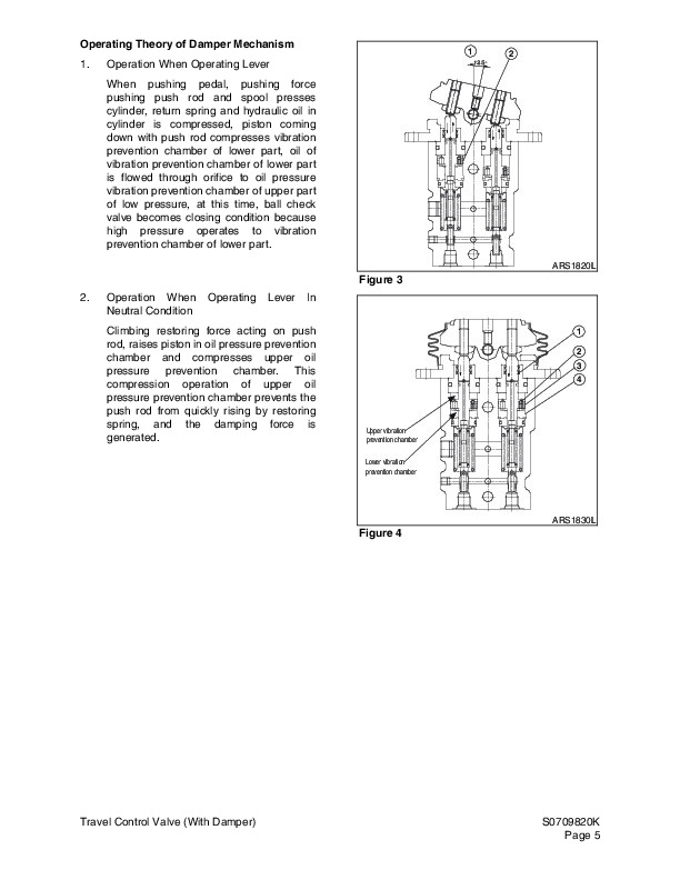
Travel Control Valve (With Damper)…..460
General Description…..462
Troubleshooting, Testomg amd Adjustment…..467
Removal…..468
Disassembly…..470
Cleaning and Inspection (Wear Lmits and Tolerances)…..476
Reassembly…..477
Installation…..482
Start-up Procedures…..483
Hydraulic Schematic (S300LC-V)…..484
General Description…..486
Solar 300LC-V…..487
Electrical System…..490
Electrical System…..491
Troubleshooting – Electrical System…..494
Overview…..495
Electric Supply System…..496
Engine Starting Circuit…..497
Engine Preheating System…..499
Engine Stop System…..500
Charging System…..503
Monitoring System…..504
Operation…..508
Warning and Indicator Lights…..510
Initial Operation…..512
Mode Select Switch…..513
Graphic Information Area Display…..514
Main Menu…..516
Special Menu…..518
Electronic Hydraulic Control System (e-EPOS)…..532
Power Mode Control…..534
Power Mode Control – Circuit Diagram…..538
Trenching Mode Control…..540
Trenching Mode Control – Circuit Diagram…..542
Engine Control System…..543
Engine Control Motor…..544
Engine Control Dial…..545
Engine Control Circuit Diagram…..547
Automatic Deceleration Control (Auto Idle Control)…..548
Engine Overheat Protection System…..549
Power Boost Mode…..550
Automatic Travel Speed Control…..552
Engine Control Device – Adjustment…..554
Self-diagnostic Function…..557
Engine Throttle Controller…..559
Wiper System…..560
Lighting System…..562
Overload Warning Device…..564
Electrical Schematic (S300LC-V)…..565
General Description…..567
Solar 300LC-V…..568
Attachment…..571
Boom and Arm…..572
Front Attachment Pin Specifications…..574
Front Attachment-Removal and Installation…..575
Installation…..578
Start-up Procedures…..579
Bucket…..580
Bucket Tooth Inspection and Replacement…..582
Bucket O-ring Replacement…..585
Bucket Shimming Procdures…..587
Bucket Attachment, Removal and Reversal…..588
Solar 300LC-V Operation and Maintenance Manual 022-00020E…..590
Safety…..596
To the Operator of a Daewoo Excavator…..596
Learn the Signal Words Used with the Safety Alert Symbol…..598
Location of Safety Labels…..599
1. Warnings for Operation, Inspection and Maintenance (190-00688, 190-00092)…..600
2. Warnings for High Voltage (190-00689, 190-00096)…..600
3. Warnings When Opening a Front Window (190-00690, 190-00093)…..600
4. Warnings for a High Pressure Cylinder (190-00122)…..601
5. Warnings When Adjusting Track Tension (2190-3386A, 190-00521)…..601
6. Warnings for Leaving Operator’s Seat (190-00693, 190-00094)…..602
7. Warnings for Batteries Maintenance (2190-2533A, 190-00100)…..602
8. Warnings for High Temperature Hydraulic Oil (190-00691, 190-00097)…..603
9. Warnings for Hot Coolant (190-00692, 190-00097)…..603
10. Warnings for Handling an Accumulator (190-00703, 190-00099)…..603
11. Warnings for Rotating Parts (190-00694, 190-00095, 190-00557)…..604
12. WArning Tag – Used When Inspection and Maintenance (190-00695, 190-00098)…..604
13. Warning for a Hot Surface (19000648)…..605
14. Caution for Hood (190-00522)…..605
15. Keep Out of the Swing Area (2190-3379, 190-00090)…..605
16. Warnings for Front Attachments (190-00652)…..606
Summary of Safety Precautions for Lifting in Digging Mode…..607
Unauthorized Modifications…..608
General Hazard Information…..608
Safety Rules…..608
Safety Features…..608
Inside Operator's Compartment…..609
Clothing and Personal Protective Items…..609
Mounting and Dismounting…..610
Fuel, Oil and Hydraulic Fluid Fire Hazards…..611
Precautions When Handling Fluids at High Temperature…..611
Asbestos Dust Hazard Prevention…..612
Injury from Work Equipment…..612
Fire Extinguisher and First Aid Kit…..613
Protection from Falling or Flying Objects…..613
Attachment Precautions…..614
Accumulator…..614
Indoor Ventilation…..615
Emergency Exit…..615
Before Starting Engine…..616
Work Site Precautions…..616
Checks Before Starting Engine…..617
Engine Starting…..618
Before Operating Machine…..618
Machine Operation…..619
When Swinging or Changing Direction of Travel…..619
Travel Precautions…..619
Traveling on Slopes…..620
Prohibited Operations…..621
Precautions for Operation…..621
Avoid High-voltage Cables…..622
Operate Carefully on Snow, Ice and in Very Cold Temperatures…..622
Operations on Slopes…..623
Parking Machine…..623
Never Let Anyone Ride on Attachment…..623
Maintenance…..624
Warning Tag…..624
Clean Before Inspection or Maintenance…..624
Proper Tools…..625
Use of Lighting…..625
Fire Prevention and Explosion Prevention…..625
Burn Prevention…..626
Welding Repairs…..627
Precautions for Removal, Installation, and Storage of Attachments…..627
Precautions when Working on Machine…..628
Lock Inspection Covers…..628
Crushing Prevention and Cutting Prevention…..628
Track Tension Adjustments Require Caution…..629
Supports and Blocking for Work Equipment…..629
Action When Abnormally Is Found During Inspection…..630
Precautions with High Pressure Line, Tubes and Hoses…..630
Waste Materials…..631
Battery…..632
Battery Hazard Prevention…..632
Boost Starting or Charging Engine Batteries…..633
Towing…..634
Precautions When Towing…..634
Shipping and Transportation…..635
Obey State and Local Over-the-Road Regulations…..635
Excavator Rated Lift Capacity Tables…..636
Operating Controls…..642
Component Locations…..643
Operator’s Area…..645
Operational Controls and Panels…..646
1. Starter Switch…..647
2. Engine Speed Control Dial…..647
3. light Switch…..648
4. Wiper Switch…..648
5. Windshield Washer Switch…..649
6. Travel Speed Selection Switch…..649
7. Stereo On/Off Switch…..650
8. Cab Work Light Switch (Optional)…..650
9. Warning Light Switch (Optional)…..650
10. Travel/Swing Alarm Switch (Optional)…..651
11. Overload Warning Switch (Optional)…..651
12. Heater and Air Conditioner Control Panel…..652
13. Cigar Lighter…..652
14. Power Socket for 12 Volt…..652
15. Horn Switch (Left-hand Work Lever (Joystick))…..653
16. Booster Switch (Right-Hand work lever (Joystick))…..653
17. Breaker Switch (Right-Hand Work Lever (Joystick))…..653
18. Instrument Panel…..653
19. Safety Lever…..654
Instrument Panel…..655
Functional check…..656
1. Engine Coolant Temperature Gauge…..656
2. Fuel Gauge…..656
3. Multifunction Gauge and Graphic Information Area…..657
4. Digital Clock…..657
5. Hour Meter…..657
6. Charge Warning Light…..658
7. Engine Oil Pressure Warning Light…..658
8. Coolant Temperature Warning Light…..658
9. Preheating Completion Light…..659
10. Work Light Indicator Light…..659
11. Overload Warning Light (Optional)…..659
Multifunction Gauge and Graphic Information…..660
Communication Indicator…..660
Communication Error Warning…..661
1. Engine Speed…..661
2. Battery Voltage…..661
3. Front Hydraulic Pump Pressure…..662
4. Rear Hydraulic Pump Pressure…..662
5. Abnormal State Warning of Filters…..663
Mode Selection Buttons…..664
1. Power Mode Selection Button…..664
2. Trenching Mode Selection Button…..665
3. Auto Idle Selection Button…..665
4. Display Selection Button…..666
Setting Method for Main Menu…..667
Main Menu…..667
Language…..668
Set Clock…..668
Filter / Oil Info…..669
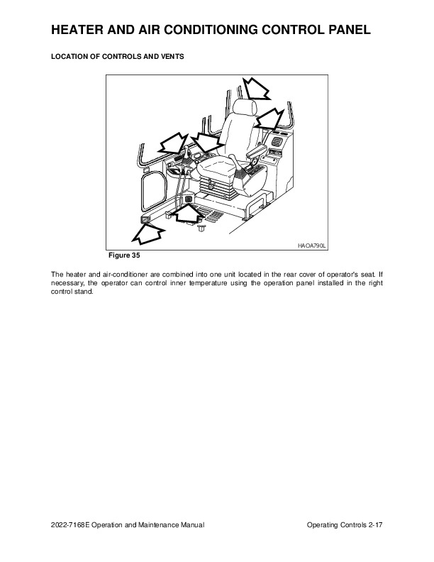
Heater and Air Conditioner Control Panel…..671
Location of Controls and Vents…..671
Operation Panel…..672
1. Fan and Air-conditioner Switch…..672
2. Fan Speed Selection Switches…..673
3. Temperature Control Switch…..673
4. Air Outlet Selection Switch…..674
5. Ventilation Selection Switch…..675
Memory Function of Used Mode…..675
Additional Operating Instructions…..675
Stereo…..676
Security and Area Code Setting…..676
Order to Set Up Security and Area Code…..676
Front Panel…..677
1. Power/Volume Control Knob…..677
2. Sound Mode Selection Button…..677
3. Band Selection Switch…..678
4. Tuning Up/Down…..678
5 & 6. Auto Memory and Preset Scan Button / Preset Station Button…..679
7. Tape Slot…..679
8. Tape Ejection Button…..679
9. Cassette and Program Buttons…..680
10. Security Warning LED…..680
11. Scan…..680
12. LCD…..681
Care of Stereo…..681
Fuse Boxes…..683
Miscellaneous Electrical Devices…..684
1. Cab Light…..684
2. Pilot Cutoff Switch…..684
3. Circuit Breaker…..684
4. Fusible Link…..685
Seat Adjustment…..686
1. Forward / Backward Adjustment (Figure 83)…..686
2. Adjusting the Seat's Tilt and Seat Height (Figure 83)…..686
3. Weight Adjustment (Figure 83)…..686
4. Adjusting Reclining (Figure 83)…..686
5. Moving the Total Seat Setting Forward/Backward (Figure 83)…..687
6. Angle Adjustment of Armrest (Figure 84)…..687
7. Headrest (Figure 84)…..687
Seat Belt…..688
Seat Belt Locking and Unlocking…..688
Ceiling Cover…..689
Opening the Ceiling Cover…..689
Closing the Ceiling Cover…..689
Front Windows…..690
Front Upper Window…..690
Front Bottom Window…..692
Door Side Latch…..693
Miscellaneous Access Covers and Doors…..694
Side Door…..694
Battery Box Door…..694
Engine Cover…..694
Cab Storage Compartments…..695
Ashtray…..695
Emergency Glass Breaking Tool…..696
Operation…..698
To Handle a New Excavator…..698
Lubrication and filters…..698
Starting and Stopping the Engine…..699
Inspection Before Starting Engine…..699
Operational Checks Before Starting Engine…..699
Engine Start…..701
Cold Weather Starting…..703
Starting Engine With a Booster Cable…..705
Hydraulic System Warm-up…..707
Hydraulic System Warm-Up – Cold Weather…..708
Engine Shut Down…..709
Check and Confirmation After Stopping Engine…..710
Safety Lever…..711
Travel…..712
Automatic Travel Speed Control…..712
General Travel Instructions…..713
Travel Control Lever Operation…..715
Operating Instructions…..717
Engine Speed Control…..717
Mode Selection…..719
Work Levers (ISO Style)…..721
Operating Precautions…..722
Working in Water…..726
Parking Excavator…..727
Towing Procedure…..728
Hydraulic Breaker…..729
Selection of Hydraulic Breaker…..729
Hydraulic Hoses and Tubing for Breaker…..729
Hydraulic Breaker Operation…..729
To activate breaker;…..731
Hydraulic Oil and Filter Service Intervals…..732
Operating Techniques…..733
Lifting…..733
Operation Under Unusual Conditions…..735
Operation In Extreme Cold…..735
Operation In Extreme Heat…..735
Operation In Dusty Or Sandy Areas…..736
Operation In Rainy or Humid Conditions…..737
Operation In Salt Water Areas…..737
Operation at High Altitudes…..737
Inspection, Maintenance and Adjustment…..738
Serial Numbers…..739
Safety Precautions…..739
Preliminary Work Machine Setup for Maintenance…..740
Table of Recommended Lubricants…..742
Fluid Capacities…..744
Lubrication and Service Chart…..744
Maintenance Intervals…..747
10 Hour / Daily Service…..747
50 Hour / Weekly Service…..747
250 Hour / Monthly Service…..747
500 Hour / 3 Month Service…..748
1000 Hour / 6 Month service…..748
2000 Hour / Yearly Service…..748
4000 Hour / Biennial Service…..748
10 Hour / Daily Service…..749
Grease Boom, Arm and Front Attachment Pins (for first 100 hours)…..749
Check Engine Oil Level…..749
Check Level of Hydraulic Oil Tank…..750
Check for Leaks in the Hydraulic System…..751
Check Fuel Level…..752
Check for Leaks in the Fuel System…..752
Check Water Separator and Drain Water As Required…..753
Check Oil Level of Swing Reduction Device…..754
Clean Dust Net in Front of Oil Cooler…..755
Check Cooling System and Refill As Required…..755
Check Level of Window Washer Liquid…..756
Inspect the Bucket Teeth and Side Cutters for Signs of Wear…..756
Inspect Engine Fan Blade…..756
Check Air Intake System…..757
Inspect Seat Belt for Proper Operation…..757
Inspect the Structure for Cracks and Faulty Welds…..757
Check the Operation of All Switches…..757
Check the Operation of All Exterior Lights, Horn and Control Console Indicator and Monitor Lights…..757
Start Engine, Check Starting Ability, and Observe Exhaust Color at Start-up and at Normal Operati……758
Check Operation of All Controls…..758
50 Hour / Weekly Service…..759
Perform All 10 Hour / Daily Service Checks…..759
Grease Boom, Arm and Front Attachment Pins…..759
Grease Swing Bearing…..761
Drain Water and Sediment from Fuel Filter…..762
Drain Water and Sediment from Fuel Tank…..762
Check Engine Fan Belt for Cracks, Wear and Correct Tension (After First 50 Hours)…..762
Change Engine Oil and Filter (After First 50 Hours)…..762
Inspect the Track Assemblies for Proper Tension and Loose, Worn or Damaged Parts (Links, Shoes, R……762
250 Hour / Monthly Service…..763
Perform All 10 hour / daily and 50 Operating Hour Service Checks…..763
Change Swing Reduction Device Oil (Drain and Refill After First 250 Hours)…..763
Clean Outer Element of Two Stage Air Cleaner…..763
Check Engine Fan Belt Tension…..764
Check Engine Fan Belt Wear…..765
Change Engine Oil and Filter…..766
Check Oil Level In Travel Reduction Device (One on Each Side of Unit)…..767
Change Oil in Travel Reduction Device (One on Each Side of Unit) (After First 250 Hours)…..767
Replace Full Flow Hydraulic Oil Filter (After First 250 Hours)…..767
Change Pilot Filter (After First 250 Hours)…..767
Inspect Pins and Bushings of the Front End Attachments for Signs of Wear…..767
Check the Fluid Levels in the Batteries and the Battery Charge Levels…..767
Inspect for Any Loose or Missing Nuts and Bolts…..767
Inspect Fuel System Hose Clamps…..767
500 Hour / 3 Month Service…..768
Perform All Daily (10 Hour), 50, and 250 Operating Hour Service Checks…..768
Grease Swing Gear and Pinion…..768
Replace Full Flow Hydraulic Oil Filter…..769
Change Pilot Filter…..770
Clean Air Conditioning Filter…..771
Clean Radiator, Oil Cooler, Intercooler and Air Conditioner Condenser Core…..772
Replace Outer and Inner Air Cleaner Elements…..773
Change Fuel Filter…..774
1000 Hour / 6 Month Service…..776
Perform All Daily (10 Hour), 50, 250 and 500 Operating Hour Service Checks…..776
Grease Swing Reduction Device…..776
Change Swing Reduction Device Oil…..776
Change Oil in Travel Reduction Device (One on Each Side of Unit)…..777
Change Radiator Coolant…..778
Clean Fuel Injection Priming Pump Strainer…..779
Check Air Conditioner Refrigerant…..780
Check and Adjust Engine **…..781
2000 Hour / Yearly Service…..782
Perform All Daily, 50, 250, 500 and 1,000 Operating Hour Service Checks…..782
Check Alternator and Starter**…..782
Check All Rubber Anti-vibration Shock Mounts…..782
Perform and Record the Results of the Cycle Time Tests…..782
Inspect Machine to Check for Cracked or Broken Welds or other Structural Damage…..782
Check, Adjust Valve Clearance **…..782
Check Head Bolt Torques…..782
Hydraulic Oil Exchange and Suction Strainer Cleaning…..782
4000 Hour / Biennial Service…..785
Major Parts – Periodic Replacement…..785
Venting and Priming Hydraulic System…..786
Main System Pump…..786
Hydraulic Cylinders…..786
Swing Motor…..787
Air Release of Travel Motor…..787
General Venting…..787
Handling of Accumulator…..788
Fuel Transfer Pump (Option)…..789
Electrical System…..791
Battery…..791
Fuses…..793
Air Conditioning System…..795
Check Control Panel…..795
Check Air Conditioner Hoses…..795
Check Condenser…..795
Check Magnetic Clutch…..795
Check Belt Tension…..795
Bucket…..796
Bucket Tooth Replacement…..796
Bucket O-ring Replacement…..797
Bucket Shimming Procedures…..799
New Bucket Installation…..799
Shimming Procedures for Installed Bucket…..799
Track Tension…..800
Bolt and Nut Inspection…..802
Maintenance in Special Conditions…..803
Long Term Storage…..804
Transportation…..806
Loading and Unloading…..806
Lifting With Sling…..809
Troubleshooting…..810
Engine…..810
Hydraulic System…..811
Swing System…..812
Travel System…..813
Electrical System…..813
Specification…..816
Standard Specification…..816
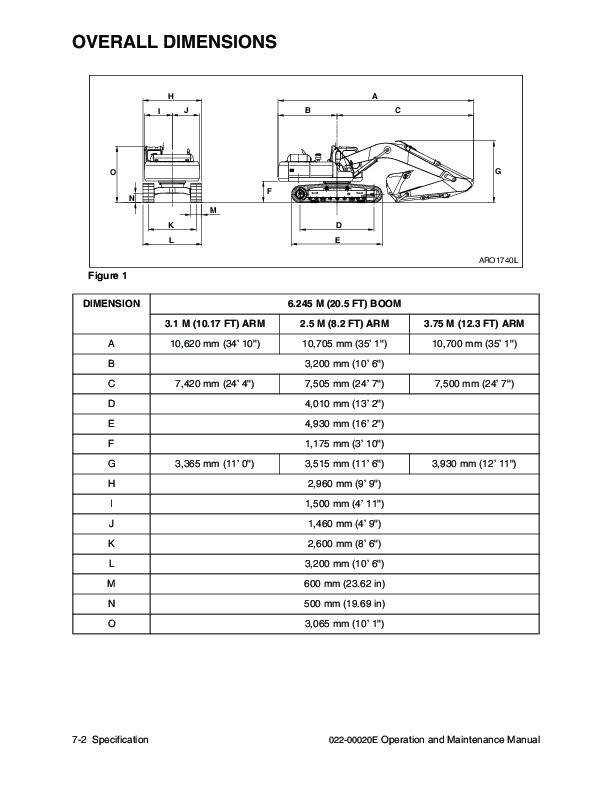
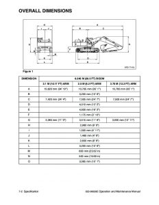
Overall Dimensions…..817
Working Range…..818
Approximate Weight of Workload Materials…..819
Index…..822
electric CIRCUIT…..828
hydraulic CIRCUIT…..829
Daewoo S300LC-V EXCAVATOR Service Repair Manuals
INSTANT DOWNLOAD