Complete repair service manual for Daewoo Solar 210W-V Excavator, with all the workshop information to maintain, diagnostic, repair, and rebuild like professional mechanics.
Daewoo Solar 210W-V Excavator workshop service & repair manual includes:
* Numbered table of contents easy to use so that you can find the information you need fast.
* Detailed sub-steps expand on repair procedure information
* Numbered instructions guide you through every repair procedure step by step.
* Troubleshooting and electrical service procedures are combined with detailed wiring diagrams for ease of use.
* Notes, cautions and warnings throughout each chapter pinpoint critical information.
* Bold figure number help you quickly match illustrations with instructions.
* Detailed illustrations, drawings and photos guide you through every procedure.
* Enlarged inset helps you identify and examine parts in detail.
023-00064E – Daewoo Solar 210W-V SHOP MANUAL (Serial Number 1001 and Up).pdf
CENS21WV0002.pdf
S210W-V_HYD_CIRCUIT.pdf
Total Pages: 824 pages
File Format: PDF
Language: English
TABLE OF CONTENTS
Safety
Wheel Excavator Safety … S0102025K
Specifications
Specifications for Solar 210W-V … S0202045K
General Maintenance
General Maintenance Procedures …S0302000
Standard Torques ..S0309000
Upper Structure
Cab … S0402040K
Counterweight… S0403015K
Fuel Tank.. S0405075K
Fuel Transfer Pump …S0405500
Swing Bearing..S0407010
Swing Reduction Gearbox …S0408040
Lower Structure and Chassis
Ram Lock Valve Operation..S0503000
Engine and Drive Train
Front Axle ..S0602100
Transmission (ZF 2HL-100)…S0602110
Air-Conditioner.. S0605060K
Drive Coupling (Main Pump)..S0609000
Hydraulics
Hydraulic System Troubleshooting, Testing and Adjustment … S0702115K
Accumulator.. S0703010K
Center Joint (Swivel)..S0704070
Cylinders..S0705000
Swing Motor…S0707250
Travel Motor…S0707350
Main Pump (With Regulator, Steering Pump and Brake Pump)..S0708430
Brake Supply Valve …S0709220
Counterbalance Valve …S0709300
Main Control Valve (Toshiba DX28) ..S0709440
Pilot Control Valve (Work Lever / Joystick)… S0709451K
Steering Valve …S0709710
Dozer Control Valve.. S0709905K
Hydraulic Schematic (Solar 210W-V) … S0792101K
Electrical System
Electrical System .. S0802125K
Electrical Schematic (Solar 210W-V).. S0892101K
Attachments
Boom and Arm…S0902080
Bucket..S0904000
Publication Request for Proposed Revision
023-00064E – Daewoo Solar 210W-V SHOP MANUAL (Serial Number 1001 and Up)…2
Safety…8
Wheel Excavator Safety S0102025K…10
To the Operator of a Daewoo Excavator…12
Learn the Signal Words Used with the Safety Alert Symbol…14
General Safety Essentials…15
Accessory Applications…15
Lifting Capacity Rating Configuration…15
Location of Safety Labels…15
Summary of Safety Precautions for Lifting in Digging Mode…16
Unauthorized Modifications…17
General Hazard Information…17
Safety Rules…17
Safety Features…17
Inside Operator's Compartment…18
Clothing and Personal Protective Items…19
Breathing Masks, Ear Protection May be Required…19
Mounting and Dismounting…20
Fuel, Oil and Hydraulic Fluid Fire Hazards…21
Precautions When Handling Fluids at High Temperature…21
Asbestos Dust Hazard Prevention…22
Injury from Work Equipment…22
Fire Extinguisher and First Aid Kit…23
Protection from Falling or Flying Objects…23
Attachment Precautions…24
Accumulator…24
Indoor Ventilation…25
Emergency Exit…25
Before Starting Engine…26
Work Site Precautions…26
Checks Before Starting Engine…27
Engine Starting…28
Before Operating Machine…28
Machine Operation…29
When Swinging or Changing Direction of Travel…29
Travel Precautions…29
Traveling on Slopes…30
Prohibited Operations…31
Precautions for Operation…31
Avoid High-voltage Cables…32
Operate Carefully on Snow, Ice and in Very Cold Temperatures…32
Operations on Slopes…33
Parking Machine…33
Never Let Anyone Ride on Attachment…33
Maintenance…34
Warning Tag…34
Clean Before Inspection or Maintenance…34
Proper Tools…35
Use of Lighting…35
Fire Prevention and Explosion Prevention…35
Burn Prevention…36
Welding Repairs…37
Warning for Counterweight and Front Attachment Removal…37
Precautions for Removal, Installation, and Storage of Attachments…38
Precautions when Working on Machine…38
Lock Inspection Covers…38
Crushing Prevention and Cutting Prevention…38
Supports and Blocking for Work Equipment…39
Action When Abnormally Is Found During Inspection…40
Precautions with High Pressure Line, Tubes and Hoses…40
Waste Materials…41
Battery…42
Battery Hazard Prevention…42
Boost Starting or Charging Engine Batteries…43
Towing…44
Precautions When Towing…44
Shipping and Transportation…45
Obey State and Local Over-the-Road Regulations…45
Lifting With Sling…45
Specifications…46
Specifications for Solar 210W-V S0202045K…48
General Description…50
Component Location…51
General Dimensions…53
Dimensions…53
Working Range…55
Hydraulic Cylinders…59
Engine Specifications…61
Engine Performance Curves (DIN 6270 Standard)…63
Approximate Weight of Workload Materials…65
General Specifications…69
Hydraulic System Component Specifications…71
System Component Specifications…73
Drive System…73
Swing Mechanism…73
Brake System…74
Steering System…74
Chocking System…75
Performance Tests and Standards…76
Standards…76
Tests…77
Test Conditions…77
Travel Speed Tests…78
Swing Speed Test…79
Swing Speed Test…79
Swing Force Test…79
Cylinder Performance Tests…80
Boom Cylinders Test…80
Arm Cylinder Test…80
Bucket Cylinder Test…80
Hydraulic Cylinder Natural Drop Test…80
General Maintenance…82
General Maintenance Procedures S0302000…84
Welding Precautions and Guidelines…86
Hydraulic System – General Precautions…87
Maintenance Service and Repair Procedure…88
General Precautions…88
Hydraulic System Cleanliness and Oil Leaks…89
Maintenance Precautions for Hydraulic System Service…89
Oil Leakage Precautions…89
Cleaning and Inspection…90
General Guidelines…90
Bearing inspection…91
Standard Torques S0309000…98
Torque Values for Standard Metric Fasteners…100
Torque Values for Standard U.S. Fasteners…101
Type 8 Phosphate Coated Hardware…103
Torque Values for Hose Clamps…104
Torque Values for Split Flanges…105
Torque Wrench Extension Tools…106
Torque Multiplication…106
Other Uses for Torque Wrench Extension Tools…107
Tightening Torque Specifications (Metric)…107
Upper Structure…110
Cab S0402040K…112
Removal…114
Installation…117
Counterweight S0403015K…120
General…122
Removal…124
Installation…126
Fuel Tank S0405075K…128
General Description…130
Parts List…131
Specifications…132
Removal…133
Installation…137
Start-up Procedures…139
Fuel Transfer Pump S0405500…140
General Description…142
Theory of Operation…142
Troubleshooting…143
Replacement of Rotor and Vane…143
Replacement of Rear Cover…144
Replacement of Armature…145
Swing Bearing S0407010…146
Swing Bearing Maintenance…148
Operating Recommendation…148
Measuring Swing Bearing Axial Play…148
Measuring Bearing Lateral Play…148
Swing Bearing Basic Operation…149
Rebuilding Swing Bearing…149
Swing Reduction Gearbox S0408040…152
General Description…154
Theory of Operation…154
Parts List…155
Specifications…156
Special Tools and Materials…157
Special Tools…157
Troubleshooting, Testing and Adjustment…158
Removal…159
Disassembly…161
Cleaning and Inspection (Wear Limits and Tolerances)…166
Reassembly…167
Installation…176
Lower Structure and Chassis…178
Ram Lock Valve Operation S0503000…180
Theory of Operation…182
Engine and Drive Train…184
Front Axle S0602100…186
Special Tools…188
Hub Nut Tool…188
Disassembly…189
Planetary End…189
Differential Gear…196
Cleaning and Inspection (Wear Limits and Tolerances)…201
Reassembly…202
Differential Gear…202
Planetary End…213
Start-up Procedures…228
Axle Lubrication…228
Transmission (ZF2HL-100) S0602110…230
Transmission Operation…233
Special Tools…234
Hub Nut Tool…234
Transmission Disassembly…235
Detaching Drive (Input) Housing…235
Disassembly of Input Shaft and Brake Assembly…236
Disassembly of Clutch…238
Disassembly of Planetary Carrier…243
Disassembly of Shift Lever and Helical Gear…244
Disassembly of Shift Lock (Version A)…249
Disassembly of Shift Lock (Version B)…251
Final Drive Disassembly…253
Rear Axle Disassembly…257
Differential Gear Disassembly…264
Cleaning and Inspection (Wear Limits and Tolerances)…269
Differential Gear Reassembly…270
Rear Axle Reassembly…282
Final Drive Reassembly…297
Transmission Reassembly…302
Reassembly of Helical Gear…302
Reassembly of Shift Lever…304
Reassembly of Planetary Carrier…305
Adjusting Shift Lever…307
Pre assembling and Installing Clutch…308
Checking Clutch…315
Reassembly of Brake and Input Shaft Assembly…316
Installing Drive (Input) Housing…320
Assembly of Shift Lock (Version A)…323
Assembly of Shift Lock (Version B)…327
Installing Oil Pump…329
Installing Screw Plugs and Oil Lines…332
Start-up Procedures…333
Axle Lubrication…333
Lubrication…333
Air-Conditioner S0605060K…334
General Description…336
Refrigerant Circulation…338
Control Panel…340
Control Specifications…341
Temperature Level Control and Display…342
Air Discharge According to Path Selection…343
Air-conditioning System Circuit Diagram…345
Troubleshooting…347
Weight of R134a Gas Used In Machines…350
Refrigerant System Repairs…352
Refrigerant Safe Handling Procedures…352
Repair and Replacement Procedure…353
Refrigerant Recovery…355
Vacuuming Refrigerant System…355
Leakage Check…356
Refrigerant Charging…357
Inspecting System For Leakage…359
Drive Coupling (Main Pump) S0609000…360
Drive Coupling…362
Special Tools…363
Kawasaki / Tong Myung Pump Tool…363
Uchida Pump Tool…366
Drive Coupling Installation…367
Installation Procedure…372
Hydraulics…374
Hydraulic System Troubleshooting, Testing and Adjustment S0702115K…376
Hydraulic System – General Notes…379
Operation of Working Components…380
Boom Operating Circuit…380
Boom Up Circuit…380
Boom Down Circuit…380
Arm Operating Circuit…381
Arm Crowd Circuit…381
Arm Dump Circuit…382
Bucket Operating Circuit…382
Bucket Crowd Circuit…382
Bucket Dump Circuit…383
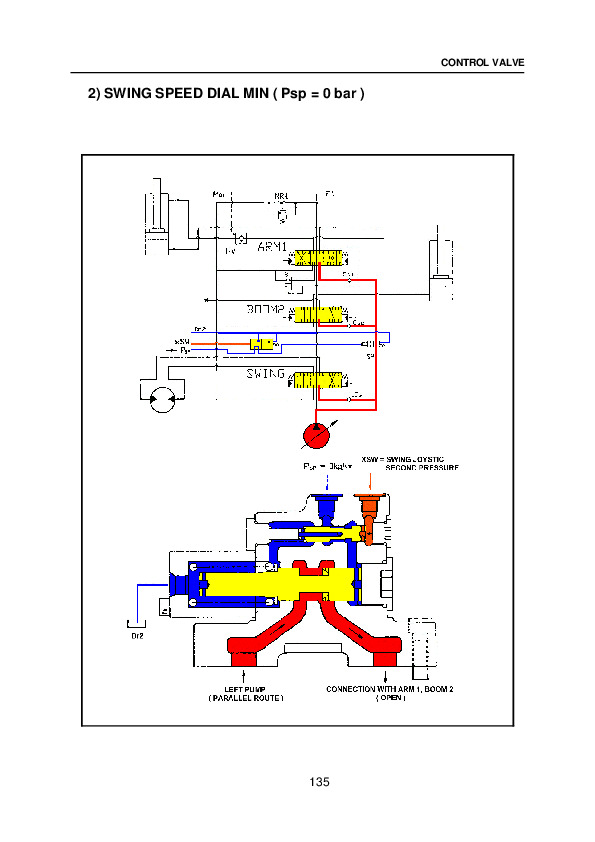
Swing Operating Circuit…384
Right Swing Operating Circuit…384
Left Swing Operating Circuit…384
Swing Relief Valve and Make-up Valve…384
Procedural Troubleshooting Baseline Recommendations…385
Initial Checks and Tests to Establish Operating Condition of the Excavator…385
Pilot Pressure…386
Adjustment and Testing…386
Power Mode Valve…387
Current Signal and Hydraulic Pressure Adjustments…387
Boom/Swing Priority Valve…388
Control Valve Pressure and Current Adjustments…388
Pressure Up Valve…389
Checks and Adjustments…389
Pump Input Power Control…390
Pump Regulator Adjustment…390
Flow Meter and Flow Meter Kit Installation and Testing…393
Swing System Troubleshooting…394
Precautions/Initial Checks…394
Swing Relief Valve Checking and Adjustment…394
Troubleshooting – Swing Gearbox…396
Troubleshooting – Hydraulic Problems…397
Troubleshooting – Control Valve…399
Troubleshooting – Joystick Control Valve…400
Accumulator S0703010K…402
General Description…404
Specifications…405
Center Joint (Swivel) S0704070…408
General Description…410
Parts List…411
Troubleshooting, Testing and Adjustment…413
Inspection…413
Testing…413
Disassembly…414
Reassembly…415
Cylinders S0705000…416
General Description…418
Theory of Operation…418
Parts List…419
Special Tools and Materials…421
Piston Nut…421
Piston Jig…425
Steel bush Jig…429
Dust Wiper Jig…433
Slipper Seal Jig…439
Slipper Seal Straightening Jig…443
Disassembly…446
Assembly…452
Swing Motor S0707250…456
General Description…458
Theory of Operation…458
Swing Motor Anti-cavitation Make-up Valve…459
Relief Valve…460
Swing Brake Operation…460
Parts List…463
Specifications…465
Special Tools…466
Disassembly…467
Cleaning and Inspection (Wear Limits and Tolerances)…474
Reassembly…476
Travel Motor S0707350…484
General Description…487
Theory of Operation…487
Parts List…489
Specifications…490
Travel Motor General Disassembly and Reassembly Instructions…491
Recommended Tools…491
Precautions for Disassembly and Assembly…491
Disassembly of Travel Motor…492
Appearance of Motor…492
Removal of counterbalance Valve…492
Removal of Outer Piping…493
Removal of Stroke Limiter…494
Removal of Oil Seal…495
Removal of Control Unit…495
Removal of Control Valve…497
Disassemble Control Valve…499
Disassemble Stroke Limiter…500
Reassemble Stroke Limiter…501
Reassemble Control Valve…501
Installation of Control Valve…502
Reassembly of Travel Motor…505
Assembly of Control Unit…505
Installation of Oil Seal…507
Installation of Stroke Limiter…508
Installation of Outer Piping…508
Installation of Counterbalance Valve…509
Main Pump (With Regulator, Steering Pump and Brake Pump) S0708430…510
General Description…513
Gear (Pilot) Pump…515
Relief Valve…515
Pump Regulator Description…516
Horsepower Control…516
Power Shift Control…516
Negative Oil Discharge (Pump Bypass) Control…516
Pump Regulator Operation…517
Pump Output Decrease…519
Pump Discharge Decrease…519
Pump Discharge Increase…519
Horsepower Control…519
Overload Protection…520
Regulator Adjustment…520
Pump Input Power Control Adjustment…521
Parts List…523
Specifications…528
Hydraulic Pump Performance Characteristics…529
Troubleshooting, Testing and Adjustment…530
Main Pump…530
Disassembly…531
General Disassembly…531
Main Pump Disassembly…532
Pump Regulator Disassembly…534
Cleaning and Inspection (Wear Limits and Tolerances)…538
Reassembly…540
Pump Regulator Reassembly…540
Main Pump Reassembly…544
Brake Supply Valve S0709220…548
Parts List…551
Specifications…552
Counterbalance Valve S0709300…554
General Description…556
While Operating to Run Forward…556
While Operating to Stop…556
While Operating to Back…556
Adjustment of Relief Valve…557
Troubleshooting…558
Counterbalance Valve…559
Recommended Tools…559
Disassembly…559
Order of Disassembly and Torque Values…560
Reassembly…561
Main Control Valve (Toshiba DX28) S0709440…566
Control Valve Operation…570
Arm Priority Circuit…571
Bucket (Junction) Circuit…573
Main Relief Valve…575
Overload Relief Valve…576
Arm Load Holding Valve…578
Boom Load Holding Valve…581
Arm Regeneration…583
Boom Regeneration…585
Foot Relief Valve…586
Parts List…587
Specifications…596
Control Valve Drawing and Hydraulic Circuit…597
Disassembly and Reassembly…602
General Disassembly…602
General Reassembly…602
Plunger Replacement…603
Main Plunger Element – Disassembly and Assembly…604
Tool…604
Main Relief Valve…607
Overload Relief Valve…610
Arm Load Holding Valve…612
Boom Load Holding Valve…615
Arm Regeneration Valve…617
Bucket Unity Check…618
Foot Relief Valve…619
Center Bypass Valve (CB Valve)…620
Boom Parallel Switch Valve…621
Boom Unity Check Valve…623
Check Valve – Locations…624
Check Valve…625
Pilot Control Valve (Work Lever / Joystick) S0709451K…628
General Description…630
Theory of Operation…630
Parts List…631
Specifications…632
Removal…633
Disassembly…636
Cleaning and Inspection (Wear Limits and Tolerances)…640
Reassembly…641
Installation…646
Start-up Procedures…647
Steering Valve S0709710…648
General Description…650
Theory of Operation…651
Parts List…653
Specifications…654
Special Tools and Materials…655
Special Tools…655
Disassembly…657
Reassembly…666
Dozer Control Valve S0709905K…680
Parts List…682
Specifications…683
Hydraulic Schematic (Solar 210W-V) S0792101K…684
General Description…686
Solar 210W-V…687
General Notes…691
Electrical System…692
Electrical System S0802125K…694
Troubleshooting – Electrical System…698
Overview…699
Electric Supply System…700
Engine Starting Circuit…701
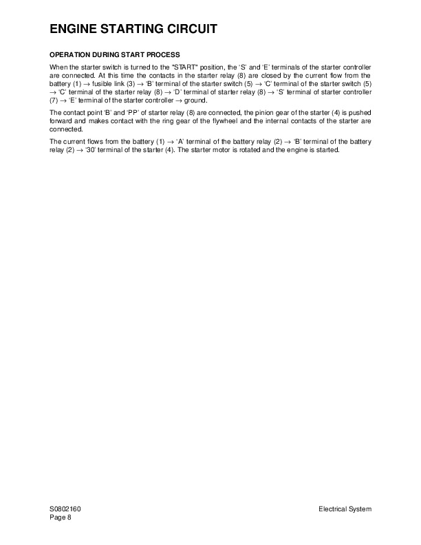
Operation During Start Process…701
Operation After Start Process…702
Engine Preheating System…703
Engine Stop System…704
Charging System…707
Monitoring System…709
Instrument Panel…711
Monitoring System Schematic…713
Operation…715
Instruments…715
Warning and Indicator Lights…717
Control Unit…719
Operation Schematic…719
Operation Specification…720
Console Warning Light…721
Initial Operation…723
Mode Select Switch…724
Graphic Information Area Display…725
Overview…725
Main Menus for the Graphic Display Area…726
Menu Selection Buttons…726
Main Menu…727
Language setting…727
Time Setting…727
Filter/Oil information…728
Special Menu…729
Entering/Accessing and Exiting/Escaping Menus…729
Special Menu Selections…730
Electronic Hydraulic Control System (e-EPOS)…743
Power Mode Control…745
Operation…746
Throttle Position Sensor…749
Power Mode Control – Circuit Diagram…751
Work Mode Control…753
Operation…754
Work Mode Control – Circuit Diagram…755
Engine Control System…757
Engine Control Motor…758
Engine Control Dial…759
Engine Control Circuit Diagram…761
Automatic Deceleration Control (Auto Idle Control)…762
Automatic Deceleration Control Circuit…763
Operation…764
Engine Overheat Protection System…765
Power Boost Mode…766
Operation…766
Power Boost Control – Circuit Diagram…767
Cruise Control…769
Cruise Control Circuit…771
Adjusting Method of Engine Control Unit…773
Adjusting Method of Engine Control System…773
Adjusting Method of Engine RPM…775
Adjustment of TPS (Throttle Position Sensor)…780
Self-diagnostic Function…785
e-EPOS Controller…785
Engine Throttle Controller…789
Wiper System…791
Wiper Circuit…791
Wiper Operation…791
Window Washer Operation…792
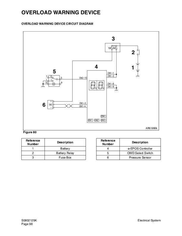
Overload Warning Device…793
Overload Warning Device Circuit Diagram…793
Electrical Schematic (Solar 210W-V) S0892101K…794
General Description…796
Solar 210W-V…797
Attachments…800
Boom and Arm S0902080…802
Front Attachment Pin Specifications…804
Front Attachment – Removal and Installation…805
Arm Removal Procedure…805
Boom Removal Procedure…807
Installation…808
Arm Installation Procedure…808
Boom Installation Procedure…808
Start-up Procedures…809
Bucket S0904000…810
Bucket Tooth Inspection and Replacement…812
Type 1…812
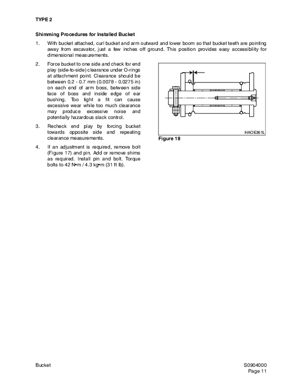
Type 2…813
Type 3…814
Bucket O-ring Replacement…816
Type 1…816
Type 2…817
Bucket Shimming Procedures…819
New Bucket Installation…819
Type 1…819
Type 2…820
Bucket Attachment, Removal and Reversal…821
Detaching the Bucket…821
Attaching The bucket…821
Reversing the Bucket…822
Publication Request for Proposed Revision…824
CENS21WV0002…826
S210W-V_HYD_CIRCUIT…827
Model…827
Daewoo Solar 210W-V Excavator Repair Service Manual