Complete workshop manual contains service, maintenance, and troubleshooting information for the 1992-2002 Iveco EuroTech, EuroStar. Diagnostic and repair procedures are covered in great detail to repair, maintain, rebuild, refurbish or restore your vehicle like a professional mechanic in local service/repair workshop. This cost-effective quality manual is 100% complete and intact as should be without any missing pages. It is the same factory shop manual used by dealers that guaranteed to be fully functional to save your precious time.
This manual for 1992-2002 Iveco EuroTech, EuroStar is divided into different sections. Each section covers a specific component or system and, in addition to the standard service procedures, includes disassembling, inspecting, and assembling instructions. A table of contents is placed at the beginning of each section. Pages are easily found by category, and each page is expandable for great detail. It is in the cross-platform PDF document format so that it works like a charm on all kinds of devices. You do not need to be skilled with a computer to use the manual.
MAKE: Iveco
MODEL: EuroTech, EuroStar
YEAR: 1992, 1993, 1994, 1995, 1996, 1997, 1998, 1999, 2000, 2001, 2002
’92-’02 EuroTech Cursor, EuroStar Cursor (603.43.391).pdf
EUROTECH CURSOR EUROSTAR CURSOR REPAIR MANUAL; 944 pages
EuroTrakker_EuroTech_EuroStar Cursor 8-10-13 EWD (603.93.121).pdf
EUROTRAKKER EUROTECH EUROSTAR CURSOR 8/10/13 REPAIR MANUAL ELECTRIC/ELECTRONIC SYSTEM; 396 pages
EXCERPT:
INDEX
Section
General 1
Engine 2
Clutch 3
Transmission* 4
Intarder – ZF hydraulic retarder 5
Propeller shafts 6
Rear axles 7
Axles 8
Suspension 9
Wheels and tyres 10
Steering system 11
Hydraulic system – Brakes 12
Scheduled Maintenance 13
603.43.391 – Iveco Trucks EuroTech Cursor, EuroStar Cursor Repair Manual ('92-'02)….2
EUROTECH CURSOR – EUROSTAR CURSOR….2
REPAIR MANUAL….2
NOTE….4
Graphs and symbols….5
INDEX….6
SECTION 1 – General….7
General….7
COMPOSITION OF MODELS….9
P.I.C. CODE NUMBER….13
Vehicle Identification Data (EUROTECH)….17
Vehicle Identification Data (EUROSTAR)….18
FILLING UP….19
International designations of lubricants and fluids….20
SECTION 2 – Engine….21
Engine….21
VIEWS OF THE ENGINE….27
TECHNICAL DESIGNATION….29
GENERAL CHARACTERISTICS….32
ASSEMBLY CLEARANCE DATA….35
FAULT DIAGNOSIS….41
DESCRIPTION….41
DIAGNOSTIC INSTRUMENTS….41
CONTROL UNIT TEST….42
ENGINE TEST….42
AUXILIARY FUNCTIONS….42
DETECTION OF MECHANICAL FAILURE….43
TIGHTENING TORQUE….46
TOOLS….51
ENGINE REMOVAL – REFITTING….61
Removal….61
Refitting….62
DISMANTLING THE ENGINE ON THE BENCH….65
REPAIR OPERATIONS….72
CYLINDER BLOCK….72
Checks and measurements….72
CYLINDER LINERS….73
Replacing cylinder liners….74
Removal….74
Fitting and checking protrusion….74
CRANKSHAFT….75
Measuring main journals and crank pins….76
Preliminary measurement of main and big end bearing shell selection data….77
Replacing the timing control gear and oil pump….85
Checking main journal installation clearance….85
Checking crankshaft end float….86
PISTON-CONNECTING ROD ASSEMBLY….87
Removal….87
Measuring the diameter of the pistons….88
Conditions for correct gudgeon pin-piston coupling….88
Piston rings….89
CONNECTING ROD….90
Bushings….91
Checking connecting rods….91
Mounting the piston rings piston assembly….92
Mounting the piston rings….92
Fitting the big end bearing shells….92
Fitting connecting rod – piston assemblies in the cylinder liners ….93
Checking piston protrusion….93
Checking assembly clearance of big end pins….95
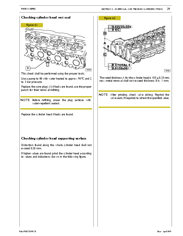
CYLINDER HEAD….95
Taking down the valves….95
Checking the planarity of the head on the cylinder block….95
VALVES….95
Removing deposits and checking the valves….95
VALVE GUIDES….96
Replacing of valve guides….97
Replacing – Reaming the valve seats….97
REPLACING INJECTOR HOLDER CASES….97
Removal….97
Checking protrusion of injectors….99
TIMING GEAR….100
Checking cam lift and pin alignment….100
Camshaft….101
Bushes….101
Replacing camshaft bushes using beater 99360499….102
Valve springs….103
Fitting the valves and oil seal ring….103
ROCKER SHAFT….104
ROCKERS….104
LUBRICATION….105
Oil pump….107
Overpressure valve….107
Oil pressure control valve….108
Heat exchanger….108
Engine oil filters….109
COOLING….110
Water pump….110
Thermostat….110
TURBOCHARGING….113
Turbocharger….113
Holset HX55V turbocharger….115
ACTUATOR ADJUSTMENT….118
VGT Control solenoid valve….118
Holset HY55V turbocharger….119
Actuator….120
Solenoid valve for VGT control….120
FEEDING….121
Fuel pump….122
Injector-pump….122
Pumping element….122
Nozzle….122
Solenoid valve….122
Replacing injectors-pump….122
INJECTOR PHASES….123
Filling phase….123
Injection phase….124
Pressure Reduction phase….124
ASSEMBLING THE ENGINE ON THE BENCH….125
DIAGRAM SHOWING THE UNDERBLOCK FIXING SCREWS TIGHTENING ORDER….127
Fitting the connecting rod-piston assembly into the cylinder liners….128
ENGINE FLYWHEEL….131
Fitting engine flywheel….131
Fitting camshaft….132
Fitting pump-injectors….133
Fitting rocker-arm shaft assembly….133
Camshaft timing….134
Phonic wheel timing….136
Adjusting rocker armclearance, intake, exhaust and pre-load of pump injector governing rocker arms….137
ENGINE COMPLETION….139
SECTION 3 – Clutch….141
Clutch….141
DESCRIPTION….143
Clutch….143
CHARACTERISTICS AND DATA….143
DIAGNOSTICS….144
TIGHTENING TORQUES….147
TOOLS….147
REMOVING AND REFITTING….148
Removal….148
Refitting….148
REMOVING AND FITTING BACK THE THRUST BEARING ….148
REPLACING THE SUPPORT BEARING OF THE CLUTCH SHAFT….148
DRIVEN PLATE CONTROL….149
Damping hub control….149
Friction seal….149
BLEEDING AIR FROM THE CLUTCH SYSTEM….149
HYDRAULIC CONTROL….150
CLUTCH ACTUATOR FOR ZF 16 S151/181/221 GEARBOX….151
Fitting and adjusting the clutch wear indicator….151
Push rod adjustment (new clutch)….152
CLUTCH ACTUATOR FOR EUROTRONIC GEARBOX….153
Clutch actuator push rod adjustment (new clutch)….153
Fitting the clutch actuator….153
Replacing the clutch actuator….153
CHECKING AND ADJUSTING THE CLUTCH PEDAL STOPS (excluded vehicles with EuroTronic gearbox)….154
Clutch stop….154
Clutch pedal idle stroke….154
Pedal timing gear stroke….154
SECTION 4 – Gearbox….155
Gearbox….155
Gearboxes: ZF 16 S 181 D.D. ZF 16 S 181 O.D. ZF 16 S 221 D.D….158
LOCATION OF GEARBOX DESCRIPTION PLATE….160
DESCRIPTION….161
OPERATION….163
Slow range….163
Fast range….164
EPICYCLIC REDUCTION GEAR CONTROL….165
Reduced speeds….165
Normal speeds….166
SPECIFICATIONS AND DATA….167
TIGHTENING TORQUES….171
TOOLS….172
GEARBOX FAULT DIAGNOSIS….177
REMOVING-REFITTING THE GEARBOX….180
Removal….180
Refitting….181
OVERHAULING THE GEARBOX….182
Servoshift gear box….182
Removal….182
Refitting….182
Disassembly….182
Assembly….184
Removing the rear box….187
Removing the epicyclic reduction gear unit (ERG)….187
Fitting the epicyclic reduction gear unit (ERG)….190
Refitting the epicyclic reduction gear unit (ERG) rear box ….193
Removing the gearbox….193
Removing the main shaft….196
Removing the drive input shaft….199
Removing the transmission shaft….200
CHECKS….200
Gearbox….200
Hubs – sliding sleeves – forks….200
Bearings….200
Shafts – gears….200
Synchronizing devices….200
BK-type single-cone synchronizing devices….200
Fitting the transmission shaft….201
Fitting the drive input shaft….201
Fitting the main shaft….202
Adjusting the main shaft….204
Fitting the gearbox….205
Oil pump….206
Adjusting the transmission shaft bearing end float….206
Drive input shaft cover….207
PNEUMATIC CONTROL OF GEARBOX….209
ZF gearboxes with INTARDER hydraulic retarder, types: 16 S 151 D.D. 16 S 181 D.D. 16 S 221 D.D….211
SPECIFICATIONS AND DATA….213
TOOLS….214
Removing the hydraulic retarder from the gearbox on the stand….221
Refitting the hydraulic retarder….221
Removing the epicyclic reduction gear unit (ERG) rear box….222
Removing the epicyclic reduction gear unit (ERG)….222
Component parts of the epicyclic reduction gear unit….225
Fitting the epicyclic reduction gear unit (ERG)….226
Refitting the epicyclic reduction gear unit (ERG) rear box….228
Gearbox EUROTRONIC 1800….230
DESCRIPTION….232
CHARACTERISTICS AND DATA….234
TIGHTENING TORQUES….237
EQUIPMENT….238
DIAGNOSIS OF MECHANICAL TYPE FAULTS….244
EUROTRONIC 1800 TRANSMISSION REMOVAL-REFITTING….247
Removal….247
Refitting….248
REPAIRS….249
Disassembly of front box….249
Disassembling the intermediate casing….250
Disassembly of rear box and epicyclic reduction unit….252
Installation of rear box and epicyclic reduction unit….254
Axial clearance regulation on epicyclic reduction gear bearing….254
Removal of primary shaft….258
Primary shaft installation….259
Removal of Splitter synchroniser….261
Installation of Splitter synchroniser….261
Forks installation-disinstallation….261
Secondary shafts….261
Central box installation….262
Shafts timing….264
Disinstallation of movement input shaft….265
Installation of movement input shaft….266
Installation of front box….266
Disinstallation of front cover….267
Installation of front cover….267
Regulation of axial clearance on movement input shaft bearing ….268
Regulation of axial clearance on secondary shaft bearings….268
EUROTRONIC IT (INTARDER)….272
CHARACTERISTICS AND DATA….272
REPAIRS….273
Disinstallation of rear box….273
Rear box installation….274
Regulation of axial clearance on epicyclic reduction gear bearing….274
Regulation of axial clearance on stator….275
CLUTCH ACTUATOR….276
Description….276
CHARACTERISTICS AND DATA….276
SAFETY RULES….277
Disinstallation….278
Installation….280
Operating checks….281
Measure of piston stroke….281
Gearbox EuroTronic 12 AS 2301 D.D….283
DESCRIPTION….285
SPECIFICATIONS AND DATA….286
TIGHTENING TORQUES….289
TOOLS….290
OVERHAULING THE GEARBOX ….295
Checks….295
Gearbox actuator….295
Removal….295
Refitting….296
Removing the rear box….296
Removing the rear box….297
Removing the epicyclic reduction gear train (E.R.G.)….298
Fitting the epicyclic reduction gear train (E.R.G.)….300
Adjusting epicyclic reduction gear train bearing end float….301
Adjusting main shaft end float….302
Synchronizing device assembly for engaging normal or reduced gears….304
Removal….304
Removing the middle box….307
Removing the main shaft….309
Removing the drive input shaft….311
Removing the splitter synchronizing device….312
Fitting the splitter synchronizing device….313
Fitting the main shaft….314
Fitting the drive input shaft….314
Splitter control fork….317
Disassembly – Assembly….317
Gear control forks….317
Removal….317
Fitting….318
Transmission shafts….319
Disassembly – Assembly….319
Fitting the middle box….319
Fitting the front box….322
Front cover….324
Removal….324
Fitting the front cover….324
Adjusting drive input shaft bearing end float….324
Adjusting transmission shaft bearing end float….325
Clutch release lever….327
Gearbox EuroTronic 12 AS 2301 D.D. with Intarder (IT)….330
SPECIFICATION AND DATA….332
OVERHAULING THE GEARBOX….333
Removing the hydraulic retarder….333
Refitting the hydraulic retarder….334
Adjusting epicyclic reduction gear train bearing end float….334
Adjusting stator end float….335
Removing the rear box….336
Removing the E.R.G….337
Fitting the E.R.G….338
EXPERIMENTAL TOOLS….343
SECTION 5 – Intarder – ZF hydraulic retarder….344
Intarder – ZF hydraulic retarder….344
LOCATION OF INTARDER HYDRAULIC RETARDER DESCRIPTION PLATE….346
GENERAL INFORMATION….347
OPERATION….347
Retarder engaged….348
Retarder disengaged….349
LAYOUT OF MAIN SYSTEM COMPONENTS ON THE RETARDER….350
REMOVING AND REFITTING THE RETARDER ON THE ZF S 181/221-OD GEARBOX….351
Removal….351
Refitting….352
Filling with oil….352
SPECIFICATIONS AND DATA….353
TIGHTENING TORQUES….354
TOOLS….355
FAULT DIAGNOSIS….357
OVERHAULING THE INTARDER HYDRAULIC RETARDER….361
Hydraulic accumulator….361
Removal….361
Fitting….361
Removing hydraulic retarder….361
Checking the component parts of the hydraulic retarder….366
Fitting the hydraulic retarder….367
For hydraulic retarders without friction reducing valves only….367
For both types of hydraulic retarder….368
Stator end float adjustment….372
SECTION 6 – Propeller shafts….374
Propeller shafts….374
SPECIFICATIONS AND DATA….376
SPECIFICATIONS AND DATA (Vehicles 4×2)….378
SPECIFICATIONS AND DATA (Vehicles 6 x 2)….379
DIAGNOSTIC….380
TIGHTENING TORQUES….382
REMOVING AND REASSEMBLING THE PROPELLER SHAFT….383
Removal….383
Reassembly….383
CHECKING THE PROPELLER SHAFT ON THE VEHICLE….384
REMOVING AND FITTING BACK THE UNIVERSAL JOINTS ….385
REMOVING AND REASSEMBLING THE SUPPORT….385
SECTION 7 – Rear axles….386
Rear axles….386
Rear axle MERITOR U 177 E whit drum brakes….388
DESCRIPTION….390
SPECIFICATIONS AND DATA….390
DIAGNOSTIC….393
TIGHTENING TORQUES….395
TOOLS….397
REMOVING THE REAR AXLE….402
FITTING BACK THE REAR AXLE….402
REAR AXLE ASSEMBLY OVERHAULING….404
WHEEL HUB OVERHAULING….404
Removal….404
Wheel hub component check….405
REPLACING THEWHEEL HUB BOLTS….406
Wheel hub reassembly….406
REMOVINGANDREASSEMBLING THE DIFFERENTIAL (with axle on stand 99322215) ….408
Removal….408
Axle casing check….408
Reassembly….409
REPAIRING THE DIFFERENTIAL….409
Removing the differential….409
Removing the gearcase….411
REMOVING THE BEVEL PINION FROM THE SUPPORT….413
Differential component check….413
Ressembling the gearcase….414
REASSEMBLING THE BEVEL PINION SUPPORT….415
Reassembling the differential housing….417
CAP OPENING ADJUSTMENT….419
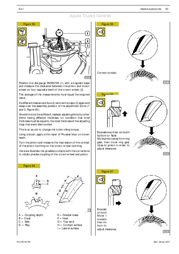
CROWNWHEEL AND PINION CONTACT CORRECTION (AFTER ASSEMBLY)….422
Instructions for the adjustment and operation check of the transmitter for the differential block operation control….425
Rear Axle MERITOR U 177 E with disc brakes….426
DESCRIPTION….428
CHARACTERISTICS AND DATA….429
TIGHTENING TORQUES….430
TOOLS….432
OVERHAULING THE REAR AXLE ASSEMBLY….436
OVERHAULING THEWHEEL HUBS….436
Removal….436
Replacing wheel hub bearings….438
Checking the parts forming the wheel hubs….438
Replacing the wheel fixing pins….438
REMOVING AND REFITTING THE DIFFERENTIAL (with axle on stand 99322215)….442
Removal….442
Checking axle housing….442
Rear axle MERITOR MS 13-175 with drum brakes….444
DESCRIPTION….446
CHARACTERISTICS AND DATA….446
Rear Axle MERITOR MS 13-175 with disc brakes….448
DESCRIPTION….450
CHARACTERISTICS AND DATA….450
Rear axle 451391/1 (R 8284)….452
DESCRIPTION….454
SPECIFICATIONS AND DATA….455
TIGHTENING TORQUES….456
TOOLS….458
REAR AXLES ASSEMBLY OVERHAUL….464
Disassembly….464
Epicycloid reduction gear disassembly….464
Wheel hub disassembly….465
CLEANING AND CHECKING WHEEL HUB AND EPICYCLOID GEAR PARTS….467
WHEEL HUB ASSEMBLY….468
Assembling the epicycloid reduction gear….470
REMOVING-REFITTING THE DIFFERENTIAL….473
REFITTING….474
REPAIRING THE DIFFERENTIAL….475
Removal….475
Gear housing disassembly….476
Removing the bevel pinion from the support….477
CHECKING THE DIFFERENTIAL COMPONENTS….479
Gear housing assembly….480
Assembling the bevel pinion support….481
Procedure to follow to determine the thickness of the bevel pinion rolling torque adjusting ring….481
Differential housing assembly….483
Gear housing bearings rolling torque adjustment….484
Axles in Tandem….488
Axles in Tandem (Intermediate) Meritor RP 160 E (R 2478)….490
DESCRIPTION….492
SPECIFICATIONS AND DATA….492
TIGHTENING TORQUES….494
TOOLS….498
EXPERIMENTAL TOOLS….505
SERVICING INTERMEDIATE AXLEASSEMBLY RP 160 E (R2478) ….508
AIR BREATHER REMOVAL-REFITTING….508
SERVICINGWHEEL HUBS….508
Checking wheel hub components….509
ASSEMBLINGWHEEL HUBS….510
REMOVING DIFFERENTIAL GEAR . TRANSFER BOX(with rear axle on stand 99322215) ….513
REFITTING DIFFERENTIAL GEAR . TRANSFER BOX (with rear axle on stand 99322215)….513
REPAIRING INTER-AXLE UNIT….514
Dismantling inter-axle unit….514
Checking inter-axle unit components….516
Fitting inter-axle unit….516
Adjusting drive input shaft bearing end float….518
Adjusting differential lock and inter-axle control pin end-stop….518
REPAIRING MAIN DIFFERENTIAL – DISMANTLING DIFFERENTIAL CASING….519
Dismantling gear cage….522
Checking differential components….522
Assembling gear cage….523
ASSEMBLING DIFFERENTIAL CASING….524
Calculatingbevel pinion positionin differential casing ….524
COMPUTATIONAL EXAMPLES….525
Determining the thickness of the bevel pinion bearing clearance adjustment rings ….525
Adjusting the cap gap….528
CORRECTING THE CROWNWHEEL AND PINION CONTACTS (AFTER ASSEMBLY)….530
REMOVING-SERVICING-REFITTIN G INTER-AXLEOUTPUT SHAFT….533
Axles in Tandem (Rear) Meritor RR 160 E (R 0878)….536
DESCRIPTION….538
SPECIFICATIONS AND DATA….538
TIGHTENING TORQUE….540
TOOLS….542
SERVICING REAR AXLE ASSEMBLY RR 160 E (R 0878)….547
AIR BREATHER REMOVAL/ INSTALLATION….547
SERVICINGWHEEL HUBS….547
REMOVING DIFFERENTIAL (with axle on stand 99322215) ….547
REFITTING DIFFERENTIAL (with axle on stand 99322215)….547
REPAIRING DIFFERENTIAL….548
Removing differential lock….548
Dismantling differential casing….549
Dismantling gear cage….550
Dismantling bevel pinion support….550
Checking differential components….554
Assembling gear cage….554
Specimen calculations….556
Assembling differential casing….556
ADJUSTING THE CAP GAP….558
CORRECTING THE CROWNWHEEL AND PINION CONTACTS (AFTER ASSEMBLY)….561
Axles in Tandem (Rear) Meritor RR 167 E (R 0878)….564
DESCRIPTION….566
CHARACTERISTICS AND DATA….566
TIGHTENING TORQUES….568
TOOLS….570
OVERHAULING REAR AXLE ASSEMBLY RR 167 E (R 0878)….576
SECTION 8 – Axles….578
Axles….578
Front axle….580
Front axle 5876/4 (F 8021) 5876/5 (F 8021) Steering central added axle 5876/2 (F 8021)….580
DESCRIPTION….582
SPECIFICATIONS AND DATA….583
FAULT DIAGNOSIS….585
TIGHTENING TORQUES….587
TOOLS….590
REMOVING AND REFITTING FRONT AXLE….594
Vehicles with mechanical front suspension….594
Removal….594
Refitting….594
REMOVING AND REFITTING FRONT AXLE….595
Vehicles with pneumatic front suspension and longitudinal bars….595
Removal….595
Refitting….596
VEHICLE CHECKS….597
Tie rods….597
Swivel heads….597
CHECKING SWIVEL HEAD PLAY….597
FRONT AXLE ASSEMBLY OVER- HAUL….598
REMOVING – REFITTINGWHEEL HUBS….598
Removal….598
Replacing wheel hub bearings….599
Replacing wheel fixing pins….600
Refitting wheel hubs….600
Checking wheel hub bearing end float….600
Measuring rolling torque….601
REMOVING AND REFITTING TRANSVERSE TIE ROD ….601
REPLACING TRANSVERSE TIE ROD SWIVEL HEADS ….602
REMOVING AND REFITTING LEVERS FOR LONGITUDINAL TIE ROD ….602
REMOVING – REFITTING LEVER FOR TRANSVERSE TIE ROD….602
REMOVING AND REFITTING PIN FOR STUB AXLE….602
Removal….602
Replacing kingpin bearing….603
Checking and adjusting clearance between stub axle and axle….604
CHECKING AND MEASURING THE AXLE BODY….605
Checking levelness of leaf spring supporting surfaces with respect to the holes for the kingpins….605
Checking angle of holes for kingpins….606
Axle 5876 (F 8021)….608
DESCRIPTION….610
SPECIFICATIONS AND DATA….611
TIGHTENING TORQUE….612
TOOLS….613
FRONT AXLE ASSEMBLY OVERHAUL….617
REMOVING – REFITTINGWHEEL HUBS….617
Removal….617
Refitting wheel hubs….618
Rear axle….620
Additional rigid rear axle 55080….620
DESCRIPTION….622
CHARACTERISTICS AND DATA….622
TIGHTENING TORQUES….623
TOOLS….624
REPAIR OPERATIONS….626
Additional rigid rear axle 56082/1….628
CHARACTERISTICS AND DATA….630
TIGHTENING TORQUES….631
TOOLS….632
Pneumaically lifted steering additional rear axle (57080)….634
CHARACTERISTICS AND DATA….636
TIGHTENING TORQUES….638
TOOLS….639
REPAIR OPERATIONS….643
PNEUMATIC LIFT GENERAL….643
GENERAL INFORMATION….643
LOCATION OF THE MAIN HYDRAULIC SYSTEM COMPONENTS ON THE VEHICLE….644
HYDRAULIC SYSTEM….645
HYDRAULIC SYSTEM OUTLINE DIAGRAM….646
VEHICLESWITH REAR AIR SPRING SUSPENSIONS AND PNEUMATIC LIFT….647
Location of the main components on the vehicle….647
Pneumatic principle diagram, rear air spring suspensions and pneumatic lift for additional axles with single wheels….648
FAULT DIAGNOSIS….649
TIGHTENING TORQUES (Steering and lifting device linkage)….652
CHARACTERISTICS AND DATA….653
Steering and third axle hydraulic system….653
MAIN HYDRAULIC SYSTEM COMPONENTS….654
HYDRAULIC ACCUMULATOR….654
Nitrogen pressure checking and recharging….654
OPERATOR CYLINDER….654
Disassembly….655
Assembly….655
Checking cylinder oil sealing on the vehicle….655
CENTRING CYLINDER….655
Disassembly….656
Assembly….656
Checking cylinder oil sealing on the vehicle….656
ADDITIONAL AXLE PNEUMATIC LIFTING DEVICE REMOVAL AND REFITTING….657
Removal….657
Refitting….657
AIR BLEEDING FROM THE HYDRAULIC CIRCUIT….658
Filling up and bleeding the power steering hydraulic circuit (circuit 1)….659
Filling up and bleeding the power steering hydraulic circuit (circuit 2)….659
Wheel geometry….660
GENERAL INFORMATION….662
Steering wheel angles….662
FRONTWHEEL GEOMETRY (4X2 vehicles)….663
Positioning clips and headlights….663
Electronic compensation of rim eccentricity….664
Wheel alignment….664
Checking wheel toe-in….665
Checking wheel deviation….665
Checking camber….665
Checking kingpin angle and caster….666
Checking rear axle alignment….667
VEHICLE WHEEL GEOMETRY WITH CENTRAL ADDED AXLE (6X2 C)….667
Checking steering angles….669
Vehicle wheel geometry with steering rear added axle and pneumatic lifting….669
SECTION 9 – Suspensions….672
SUSPENSIONS….676
DESCRIPTION….676
Mechanical front suspension….676
Air spring front suspension….676
Air spring rear suspension….676
Mechanical rear suspension….676
FRONT SUSPENSION CHARACTERISTICS AND DATA….677
Front leaf spring (vehicles with mechanical suspension)….677
Front leaf spring (vehicles with air spring suspension)….678
Leaf spring for additional central axle (vehicles with air spring suspension)….679
Rear leaf spring (6×4 vehicles)….680
Front shock absorbers….682
Rear shock absorbers….683
CHECKING SHOCK ABSORBERS BRAKING CAPACITY….684
MECHANICAL FRONT SUSPENSION ASSEMBLY….686
MECHANICAL REAR SUSPENSION ASSEMBLY….688
REAR CANTILEVER SUSPENSION (6X2 – 6X4 vehicles) ….689
Removing-reassembling the central support….689
Removing-reassembling the central support shaft….689
Replacing the bearings….689
Removing-reassembling the bracket….689
Removing the central support….689
Removing the central support shaft….689
Replacing the bracket….689
Replacing the half bearings….689
Reassembling the bracket….690
Reassembling the central support shaft….691
Reassembling the central support….691
AIR SUSPENSION….693
Chassis frame lifting, lowering and self-levelling with remote control ….693
Saving Levels….693
AIR SPRING SUSPENSION ASSEMBLIES….694
Front air spring suspension for 4×2 vehicles: MP190E39/FP, LD440E43T/FP….694
Front air spring suspension for 6x2P vehicles: LD260E43Y/FS – 43Y/FP….694
Additional central axle air spring suspension for 6x2C vehicles: LD440E43TX/P….695
Rear air spring suspension for 4×2 vehicles: LD190E39/P – 43/P, MP190E39/FP….695
Rear air spring suspension for 4×2 vehicles: MP440E39T/P, LD440E43T/P….696
Rear air spring suspension for 4×2 vehicles: LD440E43T/FP….696
Rear air spring suspension for 6x2C vehicles: LD440E43TX/P….697
Rear air spring suspension for 6x2P vehicles: MP-LD260E43Y/P….697
Rear air spring suspension for 6x2P vehicles: LD260E43Y/FS-43Y/FP….698
Rear air spring suspension for 6×4 vehicles: 260E..Z/P – 440E..TZ/P….698
ATTITUDE VALUES….699
In self-levelling conditions….699
AIR SUSPENSION SYSTEM DIAGRAMS….701
Rear air suspension main diagram for 4X2P vehicles….701
Air suspension main diagram for 4x2FP vehicles….702
Rear air suspension main diagram for 4X2T/P vehicles….703
Air suspension main diagram for 4x2T/FP vehicles….704
Suspension main diagram for 4×2 FP-CT/FP-GV/FP-D vehicles….705
Suspension main diagram for 4x2FP-CM vehicles….706
Rear air suspension main diagram for 6x2Y/PS vehicles….707
Rear air suspension main diagram for 6x2Y/PT vehicles….708
Air suspension main diagram for 6x2Y/FP/FS/FT vehicles….710
Air suspension main diagram for 6x2TX/P vehicles….711
Air suspension main diagram for 6x2Y/FP/FS-GV/FS-D vehicles….712
Air suspension main diagram for 6x2Y/FP/FS-CM vehicles….713
Air suspension main diagram for 6×4 Z/P – HM vehicles….714
Air suspension main diagram for 6×4 TZ/P – HM vehicles….715
TIGHTENING TORQUES….716
Mechanical front suspension….716
Pneumatic front suspension….717
Pneumatic front suspension with bars….718
Additional central axle air suspension 6x2C vehicles….719
Rear air suspensions 4×2 + 6×2 C vehicles….720
Rear air suspensions 6×2 P/PT/FT vehicles….722
Rear air suspensions 6×2 P/PF/FS vehicles….723
Rear air suspensions 6×2 P vehicles….724
Rear air suspensions 6×4 vehicles….725
TOOLS….727
CHARACTERISTICS AND DATA….731
Relief valve….732
IDRAULIC SYSTEM MAIN COMPONENTS….732
Pneumatic system….731
Diagnostic….732
Level sensor….732
Electropneumatic distributor….733
Suspension pressure gauge….733
Air low pressure manometer switch….733
Air spring….733
DIAGNOSTIC….734
Diagnosis Instruments….734
Blink code table for ECAS .4X2 /6X4. suspension control unit….736
Blink code table for ECAS 6X2C suspension control unit….737
Blink code table for air-operated hoist ECAS 6X2 suspension control unit….738
REAR SUSPENSIONS….744
Removal….744
Refitting….744
REMOVING-REFITTING THE REAR AXLE LONGITUDINAL SUSPENSION ARM….745
REMOVING-REFITTING THE REAR ADDED AXLE LONGITUDINAL SUSPENSION ARM….745
REMOVING-REFITTING THE REAR AXLE TRIANGULAR SUSPENSION ARM….745
REMOVING-REFITTING THE REAR ADDED AXLE TRIANGULAR SUSPENSION ARM….745
Removal….745
Refitting….745
REPLACING THE SUSPENSION ARM FLEXIBLE PIN….746
Removal….746
Refitting….746
STABILIZER BAR….747
FRONT STABILIZER BAR….747
CENTRAL ADDED AXLE STABILIZER BAR (6×2 C vehicles)….747
REAR STABILIZER BAR….747
REAR ADDED AXLE STABILIZER BAR (6x2P vehicles)….747
Removal….747
Refitting….747
RUBBER BUSHINGS….750
Replacing front stabilizer bar rubber bushings….750
Replacing rear stabilizer bar rubber bushings….750
SHOCK ABSORBERS….751
Removal-refitting….751
Front axle shock absorbers (6×2 C vehicles)….751
Central added axle shock absorbers….751
Rear axle shock absorbers….751
Rear added axle shock absorbers (6×2 P vehicles)….751
Removal….751
Refitting….751
SECTION 10 – Wheels and tyres….752
Wheels and tyres….752
DESCRIPTION….754
CHARACTERISTICS AND DATA….754
Tyre inflation pressures….754
TOOLS….755
FAULT DIAGNOSIS….755
STATIC BALANCING OF THE WHEELS….758
CORRECTING RESIDUAL STATIC IMBALANCE….759
TYRE PRESSURE….759
HOW TYRE BEHAVIOUR DEPENDS ON PRESSURE….760
SECTION 11 – Steering system….762
Steering system….762
DESCRIPTION….764
4×2 vehicle control diagram (mechanical front suspension)….765
4×2 FP – 6×2 FP Vehicle steering control diagram with front air suspension and leaf spring….766
4×2 – 6×2 FP Vehicle steering control diagram with front air suspension and longitudinal bars….767
6×2 C Vehicle steering control diagram with auxiliary central axle….768
6x2p (steering rear axle) Vehicle steering control diagram with front mechanical suspension….769
6x2p (steering rear axle) Vehicle steering control diagram with front air suspension and longitudinal bars….770
6x2p (steering rear axle) Vehicle steering control diagramwithfront air suspension andand leaf spring….771
CHARACTERISTICS AND DATA….775
FAULT DIAGNOSIS….776
TIGHTENING TORQUES….781
TOOLS….782
REMOVING AND REFITTING THE POWER STEERING UNIT….784
Removal….784
Refitting….785
Removing-Fitting the Steering Lever….785
REMOVING AND REFITTING THE STEERING CONTROL ASSEMBLY….786
Removal….786
Refitting….787
BLEEDING AIR FROM THE POWER STEERING CIRCUIT….788
MEASURING PLAYS IN THE STEERING BOX DETECTED ON THE STEERINGWHEEL ….788
CHECKING THE POWER STEERING SYSTEM MAXIMUM PRESSURE….788
ADJUSTING THE HYDRAULIC STEERING LIMITING DEVICE….788
Checking the hydraulic limiting of steering with vehicle running….789
Setting the automatic hydraulic steering limit….789
Checking….789
SECTION 12 – Pneumatic system – Brakes….790
Pneumatic system – Brakes….790
SYMBOLS FOR AIR/HYDRAULIC SYSTEM CIRCUIT DIAGRAMS (TANKS AND ACCUMULATORS)….794
SYMBOLS FOR AIR/HYDRAULIC SYSTEM CIRCUIT DIAGRAMS (VALVES)….795
SYMBOLS FOR AIR/HYDRAULIC SYSTEM CIRCUIT DIAGRAMS (TANKS AND ACCUMULATORS)….801
SYMBOLS FOR AIR/HYDRAULIC SYSTEM CIRCUIT DIAGRAMS (CONVERTERS, CYLINDERS AND CALLIPERS)….802
SYMBOLS FOR AIR/HYDRAULIC SYSTEM CIRCUIT DIAGRAMS (CALLIPERS AND CYLINDERS)….803
SYMBOLS FOR AIR/HYDRAULIC SYSTEM CIRCUIT DIAGRAMS (SEMI-COUPLINGS AND COUPLING CONNECTORS)….804
SYMBOLS FOR AIR/HYDRAULIC SYSTEM CIRCUIT DIAGRAMS (SEMI-COUPLINGS AND COUPLING CONNECTORS)….805
SYMBOLS FOR AIR/HYDRAULIC SYSTEM CIRCUIT DIAGRAMS (INDICATORS AND SWITCHES)….806
SYMBOLS FOR AIR/HYDRAULIC SYSTEM CIRCUIT DIAGRAMS (BRAKES)….807
PIPES AND COUPLINGS….808
In general….808
End forming on rigid pipes….808
Bending rigid pipes….809
Cutting rigid pipes….809
Replacing flexible hoses with threaded couplings….810
Replacing flexible hoses with quick-connection couplings….811
BRAKING SYSTEM….813
Outline diagram for 4×2 vehicles 190 E…P/FP….813
Outline diagram for 4×2 vehicles 440 E…T/P-T/FP….814
Outline diagram for 6x2C vehicles 440 E…TX/P….815
Outline diagram for 6x2P vehicles 260 E…Y/PS – Y/FS – Y/FP….816
Outline diagram for 6x2P vehicles 260 E…Y/TN….817
Outline diagram for 6×4 vehicles 260 E…Z/P-HM….818
ABS-ASR system wiring diagram (for 4×2 vehicles)….819
ABS-ASR system wiring diagram (for 6x2C vehicles)….820
ABS-ASR system wiring diagram (for 6x2P vehicles)….821
ABS-ASR system wiring diagram (for 6x2P Y/TN vehicles)….822
ABS-ASR system wiring diagram (for 6×4 vehicles)….823
EBS system wiring diagram (for 4×2 vehicles) 440 E… T/P-T/FP….824
EBS system wiring diagram (for 6x2C vehicles) 440 E… TX/P….825
Layout of the main brake system components on the vehicle….826
Layout of the main ABS-ASR system components on the vehicle….827
Layout of the main EBS system components on the vehicle….828
DESCRIPTION….829
Service braking….829
Emergency braking….829
Exhaust braking….829
Parking brake….829
BRAKES….829
Front brakes (KNORR SB7 – SN7 type)….829
Rear brakes (PERROT type dia. 410 x 180 – 410 x 200) ….829
DIAGNOSTICS….830
Diagnosis Instruments….830
ABS Troubleshooting….832
EBS Troubleshooting….840
TIGHTENING TORQUES….876
TOOLS….879
SPECIFICATIONS AND DATA – AIR SYSTEM….889
CHARACTERISTICS AND DATA – BRAKES….896
CHECKING MAIN BRAKE SYSTEM COMPONENTS….900
BRAKING SYSTEM MAIN COMPONENTS….902
Compressor….902
Head locking screw tightening….902
Fault diagnosis….903
A.P.U. (Air Processing Unit)….903
Distributor with electric (vehicles not fitted with EBS)….904
Duplex Distributor with electric (vehicles not fitted with EBS) ….904
Fault diagnosis (vehicles not fitted with EBS)….904
Triple-control servo-distributor (vehicles not fitted with EBS)….905
Predominance adjustment….905
KNORR – BREMSE AC 567 B….905
WABCO 973009013….905
Fault Diagnosis….906
Trailer control servo-distributor (vehicles fitted with EBS ….906
Relief valve (towing vehicles)….906
Coupling heads….906
Parking brake control hand distributor (towing vehicles)….907
Parking brake control hand distributor (towing vehicles)….907
Fault Diagnosis (Parking brake control hand distributor (towing vehicles)….907
Rear axle electro-pneumatic modulator (for vehicles with EBS)….908
Fault Diagnosis….908
Relay valve (vehicles not fitted with EBS) ….909
Axle proportional relay valve (vehicles fitted with EBS)….909
Fault Diagnosis (vehicles not fitted with EBS)….909
Exhaust brake control pedal valve….909
Low-pressure switch….909
Controlled pressure valve….910
Fault Diagnosis….910
Dual stop valve….910
Pressure test point valve….910
Diaphragm brake cylinder (for front and added front axle disc brake) ….911
Diaphragm brake cylinder (for front and added front axle drum brake)….911
(for front and added front axle Combined brake cylinder ….911
Combined brake cylinder (for drum brake)….912
Combined cylinder emergency brake release device ….912
ANTI-SKID SYSTEMS….913
Antilock braking system (ABS)….913
Anti-skid system (ASR)….913
EBS (Electronic Brake System)….913
Electronic control unit….914
Brake antilock distributor….914
ASR electropneumatic valve….914
Revolution sensor….914
Phonic wheels….914
BRAKE REPAIR….915
KNORR SB7 type front disk brakes (vehicles not fitted with EBS)….915
KNORR SBY type front disk brakes (vehicles fitted with EBS)….916
KNORR SB7 type front disk brakes (vehicles not fitted with EBS)….915
Operation….919
CHECKS….919
KNORR SBY type front disk brakes (vehicles fitted with EBS)….916
SN7 TYPE DISK BRAKES….917
CHECKS….919
Checking the automatic play recovery system efficiency….919
Checking brake lining thickness….920
Brake lining replacement….921
Remov.-fitting back the brake calipers Remover….924
Remover….924
Refitting….925
Removing-fitting the wheel hubs….925
Removing….925
Refitting….926
SB7 BRAKE CALLIPER OVERHAULING….927
Disassembly….927
Cleaning and checking the components….927
Assembly….928
BRAKE DISC OVERHAULING….929
BRAKE DISCS TURNING AND GRINDING….929
FRONT DRUM BRAKES….930
REAR BRAKES….930
Disassembly….930
Assembly….930
REAR DISK BRAKES….930
REAR DRUM BRAKES….931
REAR DRUM BRAKES OVERHAULING….931
Disassembly….931
Turning drums….934
Replacing brake linings….934
SECTION 13 – Scheduled Maintenance….938
SCHEDULED MAINTENANCE….940
DESCRIPTION….940
Service plan….940
OPERATIONS….941
DIAGRAM OF POINTS FOR CHECKS AND/OR MAINTENANCEWORK….944
603.93.121 – Iveco Trucks EuroTrakker, EuroTech, EuroStar Cursor 8-10-13 Electrical Wiring Diagrams….946
EUROTRAKKER – EUROTECH – EUROSTAR CURSOR 8/10/13….946
REPAIR MANUAL ELECTRIC/ELECTRONIC SYSTEM….946
FOREWORD….948
GENERAL LIST OF CONTENTS….950
Introduction….952
General cautions for electric/electronic components….955
Concept of earth and electromagnetic compatibility….957
Concept of CAN LINE….962
Technical Codes….966
Graphic symbols and abbreviations….972
General….978
DESCRIPTION OF BASE SYSTEM….980
Technical and electric specifications….980
Cab structure….980
Components on the engine F2B….982
Frame structure….986
Complete vehicle with cab tilted….987
Vehicle transparency (Euro Tech/EuroStar)….988
POWER NETWORK….990
Negative network….990
Earth points on the vehicle….991
Positive network….1002
Starting….1006
MAIN COMPONENTS….1009
Interconnecting Control Unit (UCI)….1009
Central panel – Cursor 8 (On Road)….1027
Starter motor….1035
Alternator….1039
Steering column lever unit….1041
Ignition switch….1047
Front wall connectors (A) (EuroTech – EuroStar)….1048
Rear wall connector ( " )….1059
Connectors between cables (Base vehicle) Cursor 8/10/13….1066
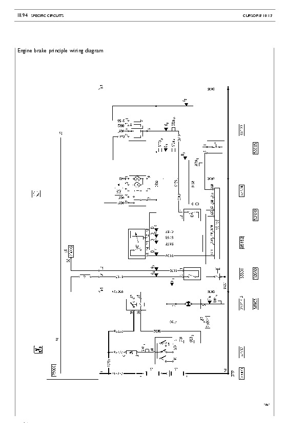
Specific circuits….1094
ABS OPERATION DIAGRAM (CURSOR 8 – 10 – 13)….1096
EDC MS6.2 (Cursor 8 – 10 – 13)….1157
ECAS….1188
IMMOBILIZER….1229
Circuit Charts….1248
Keys….1250
Chart No. 1: Start up from driver’s seat….1251
Chart No. 2: Start up from engine compartment….1252
Chart No. 3: Pre-heating….1253
Chart No. 4: Recharge….1254
Chart No. 5: Instruments (fuel level – water temperature)….1255
Chart No. 6: Instruments (engine oil and brake air pressure)….1256
Chart No. 7a: Instruments (tachograph – rev counter) F2B (on)….1257
Chart No. 7b: Instruments (tachograph – rev counter) F3A/F3B (on) – F2B/F3B (off)….1258
Chart No. 8a: Warning lights (iveco control)….1259
Chart No. 8b: Warning lights F2B (on)….1260
Chart No. 8c: Warning lights F3A/F3B (on)….1261
Chart No. 8d: Warning lights F2B/F3B (off)….1262
Chart No. 9: Sidelights (cabin interior)….1263
Chart No. 10: Sidelights (vehicle exterior)….1264
Chart No. 11: Main/dipped beam headlights….1265
Chart No. 12: Additional headlights and rear foglights….1266
Chart No. 13: Direction indicators – hazard lights….1267
Chart No. 14: Brake lights – Reverse light – Horn….1268
Chart No. 15: Windscreen wiper….1269
Chart No. 16a: Interior lighting and service F2B (on)….1270
Chart No. 16b Interior lighting and service F3A/F3B (on)….1271
Chart No. 16c: Interior lighting and service F2B/F3B (off)….1272
Chart No. 17: Rearview mirrors….1273
Chart No. 18a: Window winders F2B (on) F2B/F3B (off)….1274
Chart No. 18b: Window winders F3A/F3B (on)….1275
Chart No. 19a: ABS / ASR F2B (on)….1276
Chart No. 19b: ABS / ASR F3A/F3B (on)….1277
Chart No. 19c: ABS / ASR F2BF3B (off)….1278
Chart No. 20: EBS F3A/F3B (on)….1279
Chart No. 21a: EDC (connector B) F2B (on)….1280
Chart No. 21b: EDC (connector B) F3A/F3B (on) F2B/F3B (off)….1281
Chart No. 22a: EDC (connector a – F2B)….1282
Chart No. 22b: EDC (connector A – F3B)….1283
Chart No. 23a: EUROTRONIC 1 F2B (on)….1284
Chart No. 23b: EUROTRONIC I I F3A/F3B (on) F2B/F3B (off)….1285
Chart No. 24: Manual climate control system….1286
Chart No. 25: Automatic climate control system….1287
Chart No. 26: Additional air heating manual mode….1288
Chart No. 27: Additional air heating manual mode (GGVS)….1289
Chart No. 28: Independent heating unit manual control for cabin and engine….1290
Chart No. 29: Independent heating unit manual control for cabin and engine (TMP)….1291
Chart No. 30: Main remote control switch….1292
Chart No. 31: ADR electronic main remote control switch….1293
Chart No. 32: Air TMP emergency switch….1294
Chart No. 33: Air TMP emergency switch (French)….1295
Chart No. 34: Ground startup and recharge….1296
Chart No. 35: 15-Pole socket….1297
Chart No. 36: 2X7 Pole socket (only tractor)….1298
Chart No. 37: Heated windscreen….1299
Chart No. 38: Drier heating heated pre-filter….1300
Chart No. 39: Trip computer level 1….1301
Chart No. 40: Trip computer level1 (with main current switch)….1302
Chart No. 41A: Electronic speedometer F2B (ON)….1303
Chart No. 41B: Electronic speedometer F3A/F3B (ON) F2B/F3B (OFF)….1304
Chart No. 42: Hour counter….1305
Chart No. 43: Economy Power….1306
Chart No. 44: Central door lock….1307
Chart No. 45: Multipower takeoff….1308
Chart No. 46: Right and left beacon light….1309
Chart No. 47: Sunroof….1310
Chart No. 48: Central lubrication “Lincoln” – “Vogel”….1311
Chart No. 49: Hydraulic power steering circuit….1312
Chart No. 50: Hydraulic power steering circuit (northern countries)….1313
Chart No. 51: Headlight washer and windscreen wiper….1314
Chart No. 52: Trailer braking system….1315
Chart No. 53: Immobilizer….1316
Chart No. 54: Intarder ZF….1317
Chart No. 55: ECAS for 4X2 and 6X2 (ON)….1318
Chart No. 56: ECAS for 4X2 and tractor (ON)….1319
Chart No. 57: ECAS for 6X2 P/FP and PT/FT with additional hydraulic steering axis (ON)….1320
…
Iveco EuroTech, EuroStar Trucks Workshop Repair Service Manual 1992-2002