Complete service repair manual with electrical wiring diagrams for Hyster H360-650C TO S/N1550 (C008) & H370-700C S/N1550-UP (C008), with all the workshop information to maintain, diagnose, repair, and service like professional mechanics.
Hyster H360C-H650C (C008) & H370C-H700C workshop service repair manual includes:
* Numbered table of contents easy to use so that you can find the information you need fast.
* Detailed sub-steps expand on repair procedure information
* Numbered instructions guide you through every repair procedure step by step.
* Troubleshooting and electrical service procedures are combined with detailed wiring diagrams for ease of use.
* Notes, cautions and warnings throughout each chapter pinpoint critical information.
* Bold figure number help you quickly match illustrations with instructions.
* Detailed illustrations, drawings and photos guide you through every procedure.
* Enlarged inset helps you identify and examine parts in detail.
599974 – Hyster H360-650C TO S/N1550 (C008) & H370-700C S/N1550-UP (C008) Service Repair Manual.pdf
Total Pages: 804 pages
File Format: PDF (Internal Links, Bookmarked, Table of Contents, Searchable, Printable, high quality)
Language: English
| Section |
Part No.
|
SRM Number | Rev Date |
| FRAME |
910467
|
0100 SRM 0267
|
02/97
|
| PERKINS DIESEL ENGINES TV8.540, TV8.640 |
910760
|
0600 SRM 0269
|
08/87
|
| COOLING SYSTEM |
897934
|
0700 SRM 0626
|
11/01
|
| THREE-SPEED PS TRANS-DESCR /OPER (HYSTER) |
910188
|
1300 SRM 0017
|
06/84
|
| THREE-SPEED PS TRANS-REPAIR (HYSTER) |
910015
|
1300 SRM 0171
|
06/84
|
| THREE-SPEED PS TRANS-REPAIR (HYSTER) |
897240
|
1300 SRM 0375
|
11/01
|
| THREE-SPEED PS TRANS-REPAIR (CLARK) |
897241
|
1300 SRM 0376
|
09/97
|
| DIFFERENTIAL |
910072
|
1400 SRM 0046
|
11/03
|
| PLANETARY GEAR AXLE |
910030
|
1400 SRM 0047
|
11/03
|
| STEERING CONTROL UNIT |
899776
|
1600 SRM 0058
|
07/80
|
| STEERING AXLE |
910031
|
1600 SRM 0071
|
07/97
|
| BRAKE SYSTEM (TO S/N 1550) |
910755
|
1800 SRM 0273
|
02/97
|
| BRAKE SYSTEM (S/N 1550-UP) |
897359
|
1800 SRM 0425
|
06/89
|
| HYDRAULIC GEAR PUMPS |
910091
|
1900 SRM 0097
|
10/03
|
| HYDRAULIC SYSTEM |
910462
|
1900 SRM 0253
|
01/97
|
| REMOTE CONTROL VALVE |
910450
|
2000 SRM 0249
|
01/97
|
| MAIN CONTROL VALVE |
910451
|
2000 SRM 0250
|
01/97
|
| ATACHMENT CONTROL VALVE |
910452
|
2000 SRM 0251
|
01/97
|
| FLOW CONTROL VALVE |
910463
|
2000 SRM 0252
|
01/97
|
| TILT CONTROL VALVE |
910101
|
2100 SRM 0102
|
07/94
|
| TILT CYLINDERS |
910102
|
2100 SRM 0103
|
10/03
|
| ALTERNATOR |
899784
|
2200 SRM 0002
|
10/03
|
| STARTER |
910107
|
2200 SRM 0106
|
02/01
|
| INSTRUMENT PANEL INDICATORS and SENDERS |
910110
|
2200 SRM 0143
|
12/03
|
| UPRIGHT |
910468
|
4000 SRM 0268
|
02/97
|
| EXTENDABLE CONTAINER ATTACHMENT |
910457
|
5000 SRM 0265
|
11/97
|
| FIXED CONTAINER ATTACHMENT |
910466
|
5000 SRM 0266
|
11/97
|
| INCH (SAE) and METRIC FASTENERS |
910442
|
8000 SRM 0231
|
03/03
|
| PERIODIC MAINTENANCE (TO S/N 1550) |
910752
|
8000 SRM 0271
|
05/84
|
| DIAGRAMS |
910751
|
8000 SRM 0276
|
01/97
|
| CAPACITIES and SPECIFICATIONS (TO S/N 1550) |
910758
|
8000 SRM 0277
|
07/87
|
| PERIODIC MAINTENANCE (S/N 1550-UP) |
897381
|
8000 SRM 0440
|
08/89
|
| CAPACITIES and SPECIFICATIONS (S/N 1550-UP) |
897387
|
8000 SRM 0446
|
07/89
|
| PART NO. 599974 | |||
| Rev. 12/03 | |||
C008 (H17.00-32.00C Europe)…2
100267…4
INTRODUCTION…4
GENERAL…4
DESCRIPTION…4
REPAIRS…4
COUNTERWEIGHT…4
Removal…4
Installation…4
FENDERS…4
Installation…5
HOOD AND BALLAST COVER…5
HYDRAULIC TANK…5
Removal, H16.00-32.00C (H360-650, H370-700C)…5
Removal, H46.00-44.00B (H700-920B)…6
Repairs, All Units…6
Steam Method of Cleaning…6
Chemical Solution Method of Cleaning…7
Other Methods Of Preparation For Repair…7
Installation, H16.00-32.00C (H360-650C, H370-700C)…7
Installation, H36.00-44.00B (H700-920B)…7
FUEL TANK…7
Removal, H16.00-32.00C (H360-650C, H370-700C)…7
Removal, H36.00-44.00B (H700-920B)…7
Repair, All Units…7
Installation, H16.00-32.00C (H360-650C, H370-700C)…7
Installation, H36.00-44.00B (H700-920B)…8
RADIATOR…8
Removal, H16.00-32.00C (H360-650C, H370-700C)…8
Removal, H36.00-44.00B (H700-920B)…8
Installation, H16.00-32.00C (H360-650C, H370-700C)…8
Installation, H36.00-44.00B (H700-920B)…8
ENGINE…8
Removal, H16.00-32.00C (H360-650C, H370-700C)…8
Installation, H16.00-32.00C (H360-650C, H370-700C)…9
Removal, H36.00-44.00B (H700-920B)…9
Installation, H36.00-44.00B (H700-920B)…10
OPERATOR'S COMPARTMENT AND CAB (See FIGURE 2.)…10
General…10
Removal…11
Repairs…13
Installation…14
LABEL REPLACEMENT…16
130017…18
INTRODUCTION…18
General…18
MECHANICAL DESCRIPTION…18
General…18
Torque Converter…18
Description…18
Operation…19
Clutch Assemblies…20
Description…20
Operation…21
First Stage Shaft…21
Second Stage Shaft…22
Third Stage Shaft…23
Inching Clutch…24
HYDRAULIC OPERATION…25
Sump, Filter and Pump…25
Control Valve, H360-620B…26
Control Valve, H360-650C…28
Inching Valve…30
Description…30
Operation…30
TRANSMISSION CONTROL CIRCUIT, H360-650C…33
HYDRAULIC CIRCUITS…33
Cooling and Lubrication…33
NEUTRAL-FIRST, H360-620B…33
NEUTRAL, H360-650C…35
FORWARD-FIRST, H360-620B…35
FORWARD-FIRST, H360-650C…37
REVERSE-FIRST, H360-620B…39
REVERSE-FIRST, H360-650C…40
SHIFT FROM FIRST TO SECOND SPEED, H360-620B…40
SHIFT FROM FIRST TO SECOND SPEED, H360-650C…40
1300171…42
INTRODUCTION…42
General…42
TRANSMISSION…42
Removal…42
Disassembly…43
Cleaning and Inspection…53
Assembly…53
Installation…67
TORQUE CONVERTOR…69
Removal and Disassembly…69
Cleaning and Inspection…71
Assembly and Installation…71
INCHING CLUTCH…74
Removal and Disassembly…74
Cleaning and Inspection…76
Assembly and Inspection…76
CONTROL VALVE…80
Removal…80
Disassembly…80
Cleaning and Inspection…81
Assembly…81
INCHING VALVE…82
Removal…82
Disassembly…82
Cleaning…82
Assembly…82
Installation…83
OIL PUMP…84
Removal…84
Disassembly…84
Cleaning and Inspection…85
Assembly…85
Installation…86
RANGE SELECTOR ASSEMBLY, H360-650C…86
Removal and Disassembly…86
Assembly and Installation…88
1300375…100
INTRODUCTION…100
General…100
MECHANICAL DESCRIPTION…101
General…101
Torque Converter…101
Description…101
Operation…102
Clutch Assemblies…102
Description…102
Operation…103
Forward Shaft…104
Reverse Shaft…104
First Speed Shaft…104
Output Shaft…104
HYDRAULIC OPERATION…105
Sump, Filter And Operation…105
Shift Control Valve…107
Solenoid Valves…107
Inching Spool…107
Direction Spools…107
Range Spools…107
Modulator Valve And Manifold Block…108
Operation…109
Transmission Control System, H17.00-32.00C(H370-700C)…111
Transmission Control System, H20.00-32.00F(H440-700F)…112
Hydraulic Circuits…114
Cooling and Lubrication…114
Operation Of The Transmission, NEUTRAL…115
Operation Of The Transmission, FORWARD-FIRST…116
Operation Of The Transmission, REVERSE-FIRST…117
Operation Of The Transmission, FORWARD-SECOND…118
Operation Of The Transmission, FORWARD-THIRD-INCHING…119
1300376…120
INTRODUCTION…120
General…120
Transmission…120
Removal…120
Transmission, Disassembly…122
Cleaning…138
Inspection…138
Transmission, Assembly…141
Installation…160
Modulator Valve And Manifold Block…164
Removal…164
Disassembly…164
Cleaning And Inspection…164
Assembly…165
Installation…165
Shift Control Valve…166
Removal…166
Disassembly…166
Cleaning And Inspection…167
Assembly…167
Installation…167
Oil Pump…168
Removal…168
Disassembly…168
Cleaning And Inspection…169
Assembly And Installation…169
Transmission Control Assembly H17.00-32.00C (H360-700C)…170
Removal And Disassembly…170
Assembly And Installation…171
Transmission Control Assembly H20.00-32.00 (H440-700F/FS)…172
Removal And Disassembly…172
Assembly And Installation…174
CHECKS AND ADJUSTMENTS…174
Check The Stall Speed Of The Torque Converter…174
Check The Oil Pressure Of The Transmission…175
TROUBLESHOOTING…176
140046…178
DIFFERENTIAL…178
GENERAL…178
DESCRIPTION…178
REPAIRS…179
REMOVAL…179
DISASSEMBLY…179
ASSEMBLY…179
Assemble The Pinion, Bearings And Pinion Carrier…179
Adjust Preload For Pinion Bearings…179
Adjust Thickness Of Shim Set For The Pinion Carrier (Depth Of Pinion)…180
Assemble The Differential And Ring Gear…182
Assemble Differential Pinion And Side Gear Assembly…183
Check The Rotating Torque Of Differential Gears…184
Install The Differential And Ring Gear Assembly…185
Adjust Preload Of The Differential Bearings…186
Check Runout Of Ring Gear…186
Adjust The Gear Clearance…186
Check Tooth Contact Pattern Of The Gear Set…187
Installation Into The Axle Housing…187
SPECIFICATIONS…190
TABLE 1. GENERAL SPECIFICATIONS…190
TABLE 2. RIVET INSTALLATION PRESSURE…190
TABLE 3. PINION PRELOAD PRESSURE…190
TABLE 4. PINION ADJUSTMENT…190
TABLE 5. TORQUE SPECIFICATIONS…191
TROUBLESHOOTING…192
140047…193
INTRODUCTION…193
GENERAL…193
DESCRIPTION…193
OPERATION…193
REPAIRS…194
REMOVAL…194
DISASSEMBLY…197
ASSEMBLY AND INSTALLATION…199
TROUBLESHOOTING…202
160058…205
INTRODUCTION…205
General…205
Description…207
Operation…207
REPAIRS…208
Removal…208
Disassembly…208
Inspection…213
Assembly…213
Installation…213
CHECKS AND ADJUSTMENTS…219
TROUBLESHOOTING…220
160071…221
INTRODUCTION…221
GENERAL …221
DESCRIPTION…221
REPAIRS…222
STEERING AXLE…222
Removal…222
Installation…222
STEERING CYLINDER…222
Removal…222
Inspection…224
Assembly…224
Installation…224
HUBS, H7.00-12.50H (H150-275H), H13.50-16.00B (H300-350B), P7.00-9.00B (P150-200B)…225
Removal…225
Installation…225
HUBS, H360-620B, H16.00-30.00C, H17.00-32.00C, H700-800A, H36.00-44.00B, H36.00-48.00C, H20.00-32.00F…226
Removal…226
Installation…226
SPINDLES…226
Removal…226
Installation…226
CHECKS AND ADJUSTMENTS…228
REMOVE THE AIR FROM THE STEERING SYSTEM…228
ADJUST THE CYLINDER STOPS…228
1800273…229
INTRODUCTION…229
GENERAL…229
DESCRIPTION…229
OPERATION…231
Service Brakes…231
Parking Brake…231
REPAIRS…232
AIR TANKS…232
Relief Valve…232
Drain Valve…232
BRAKE PEDAL VALVE…233
Removal…233
Disassembly and Repair…233
Assembly…233
Installation…233
PARKING BRAKE VALVE…233
Removal…233
Disassembly and Repair…234
Assembly…234
Installation…234
AIR CHAMBERS…234
Removal…234
Disassembly…235
Inspection…236
Assembly…236
Installation…237
ACTUATOR ARMS…237
Removal…237
Installation…237
BRAKE SHOES…237
Removal…238
Cleaning…238
Repair…239
Installation…239
BRAKE DRUMS (SERVICE BRAKES)…239
DISC BRAKE ASSEMBLY (SERVICE BRAKES)…239
Brake Pads Replacement…239
Brake Caliper, Removal…240
Brake Caliper, Disassembly…240
Brake Caliper, Repair…241
Brake Caliper, Assembly…241
Brake Caliper, Installation…241
Brake Rotor, Removal…241
Brake Rotor, Installation…241
Brake Booster, Removal…241
Brake Booster, Disassembly…241
Brake Booster, Inspection…241
Brake Booster, Assembly…242
Brake Booster, Installation…242
DISC BRAKE ASSEMBLY (PARKING BRAKE)…242
Brake Pads, Replacement…242
Brake Caliper, Removal And Disassembly…243
Brake Caliper, Cleaning…243
Air Chamber, Service…244
CHECKS AND ADJUSTMENTS…244
REMOVING AIR FROM THE BRAKE SYSTEM…244
CHECK AND ADJUST THE GOVERNOR FOR THE AIR COMPRESSOR…244
ADJUSTMENT OF THE BRAKE SHOES…245
CHECK WEAR ADJUSTMENT FOR THE PARKING BRAKE…245
TROUBLESHOOTING…246
1800425…248
INTRODUCTION…248
GENERAL…248
DESCRIPTION…248
H26.00-32.00C (H550-700C)…248
H36.00-44.00B (H700-920B), H36.00-48.00C (H800-1050C)…248
OPERATION…248
Service Brakes, H26.00-32.00C (H550-700C)…248
Service Brakes, H36.00-44.00B (H700-920B), H36.00-48.00C (H800-1050C)…252
Parking Brake, H26.00-32.00C (H550-700C)…252
Parking Brake, H36.00-44.00B (H700-920B), H36.00-48.00C (H800-1050C)…253
REPAIRS…254
AIR TANKS…254
Relief Valve…254
Drain Valve…254
BRAKE PEDAL VALVES…254
Removal…254
Disassembly and Repair…255
Assembly…255
Installation…255
PARKING BRAKE VALVE…256
Removal…256
Disassembly and Repair…256
Assembly…256
Installation…257
PARKING BRAKE ACTUATOR, H26.00-32.00C (H550-700C)…257
Removal…257
Disassembly…257
Inspection…258
Assembly…258
Installation…258
PARKING BRAKE ACTUATOR, H36.00-44.00B (H700-920B), H36.00-48.00C (H800-1050C)…258
Removal…258
Disassembly…258
Inspection…259
Assembly…259
Installation…260
PARKING BRAKE ASSEMBLY…260
Removal and Installation…260
Cleaning…260
Inspection…260
Assembly and Installation…260
SERVICE BRAKE ACTUATORS…261
Removal…261
Disassembly…261
Cleaning and Inspection…261
Assembly…261
Installation…261
BRAKE CALIPERS…262
Removal…262
Disassembly…263
Cleaning…263
Inspection…264
Assembly…264
Installation…265
INCHING VALVE ACTUATOR, H36.00-44.00B (H700-920B)…265
Removal…266
Disassembly…266
Cleaning and Inspection…266
Assembly…266
Installation…266
CHECKS AND ADJUSTMENTS…267
REMOVE THE AIR FROM THE BRAKE SYSTEM…267
INCHING ADJUSTMENT…267
CHECK AND ADJUST THE GOVERNOR FOR THE AIR COMPRESSOR…267
CHECK AND ADJUST THE PRESSURE REGULATORS FOR THE PARKING BRAKE, H36.00-44.00B (H700-920B), H36.00-48.00C (H800-1050C)…267
TROUBLESHOOTING…269
1900253…271
INTRODUCTION H16.00-30.00C (H360-650C), H17.00-32.00C (H370-700C)…271
GENERAL…271
DESCRIPTION AND OPERATION…271
Right-Hand Hydraulic Pump…271
Left-Hand Hydraulic Pump…271
Auxiliary Hydraulic Pump (Left-Hand)…271
Auxiliary Hydraulic Pump (Right-Hand)…271
Main Control Valve…273
Attachment Control Valve…273
Remote Control Valve…273
Pressure Reduction Valve…273
Solenoid Valves…273
Steering Control Unit…273
INTRODUCTION H36.00-44.00B (H700-920B)…279
GENERAL…279
DESCRIPTION AND OPERATION…279
Main Control Valve…279
Attachment Control Valve…279
Remote Control Valve…279
Pressure Reduction Valve…279
Solenoid Valves…280
Steering Control Unit…281
TROUBLESHOOTING…286
SPECIFICATIONS H16.00-30.00C (H360-650C), H17.00-32.00C (H370-700C)…289
SPECIFICATIONS H36.00-44.00B (H700-920B)…290
190097…291
INTRODUCTION…291
DESCRIPTION…291
OPERATION…291
Flow Control Valve…293
Relief Valve…293
REPAIRS…294
REMOVAL…294
DISASSEMBLY…294
CLEANING…296
INSPECTION…296
ASSEMBLY…297
INSTALLATION…298
CHECKS AND ADUSTMENTS…299
CHECK THE OUTPUT OF THE PUMP…299
CHECK FOR AIR IN THE HYDRAULIC SYSTEM…299
TROUBLESHOOTING…301
2000249…304
INTRODUCTION…304
GENERAL…304
DESCRIPTION…304
OPERATION…304
REPAIRS…307
REMOVAL…307
DISASSEMBLY…307
INSPECTION…308
ASSEMBLY…308
INSTALLATION…310
ADJUSTMENT…311
TROUBLESHOOTING…311
2000250…312
INTRODUCTION…312
GENERAL…312
DESCRIPTION…312
OPERATION…312
Lift Circuit, High Speed (Light Load or No Load)…312
Lift Circuit, Normal Speed (Heavy Load)…313
Lowering…314
Two Speed Spool…315
Tilt Circuit…315
Relief Valve…316
REPAIRS…317
REMOVAL…317
DISASSEMBLY…317
CLEANING AND INSPECTION…317
ASSEMBLY…317
INSTALLATION…318
CHECKS AND ADJUSTMENTS…318
CHECKING THE RELIEF PRESSURE…318
CHECKING THE PRESSURE OF THE TWO SPEED CARTRIDGE…318
TROUBLESHOOTING…319
2000251…321
INTRODUCTION…321
GENERAL…321
DESCRIPTION…321
OPERATION…321
REPAIRS…322
REMOVAL…322
DISASSEMBLY…322
CLEANING AND INSPECTION…322
ASSEMBLY…323
INSTALLATION…323
CHECKS AND ADJUSTMENTS…324
CHECK AND ADJUST THE RELIEF VALVE…324
TROUBLESHOOTING…325
2000252…326
INTRODUCTION…326
GENERAL…326
DESCRIPTION AND OPERATION…326
FLOW REGULATORS…326
RELIEF VALVE…327
PRESSURE REDUCTION VALVE…327
TWIST LOCK SOLENOID VALVE…329
LOCK OUT SOLENOID VALVE…329
REPAIRS…330
FLOW REGULATORS…330
Removal…330
Disassembly…330
Cleaning and Inspection…330
Assembly…330
Installation…330
RELIEF VALVE…330
PRESSURE REDUCTION VALVE…330
TWIST LOCK SOLENOID VALVE AND LOCK OUT SOLENOID VALVE…330
CHECKS AND ADJUSTMENTS…331
CHECK THE CONTROLLED FLOW OF THE FLOW REGULATORS…331
CHECK AND ADJUST THE RELIEF VALVE (STEERING SYSTEM)…331
CHECK THE PRESSURE REDUCTION VALVE…332
TROUBLESHOOTING…333
2100102…335
INTRODUCTION…335
GENERAL…335
DESCRIPTION AND OPERATION…335
Tilt Forward…335
Tilt Backward…336
REPAIRS…338
REMOVAL…338
DISASSEMBLY…338
CLEANING…338
ASSEMBLY…338
INSTILLATION…339
TROUBLESHOOTING…339
2100103…340
INTRODUCTION…343
GENERAL…343
DESCRIPTION…343
REPAIRS…343
REMOVAL…343
DISASSEMBLY…343
CLEANING…343
ASSEMBLY…343
Tilt Cylinders for the XM and XMS Models…343
Tilt Cylinders with O-Ring or Single Lip Seals…345
Tilt Cylinders for H700-800A and Early Model H700-920B…345
INSTALLATION…345
Tilt Cylinders with Chevron Packing…345
CHECKS AND ADJUSTMENTS…349
CHECK THE TILT CYLINDERS FOR LEAKS…349
ADJUST THE TILT CYLINDER STROKE AND THE MAST TILT ANGLE…349
TROUBLESHOOTING…352
2200106…355
INTRODUCTION…355
GENERAL…355
DESCRIPTION AND OPERATION…355
REPAIRS…357
REMOVAL…357
DISSASEMBLY…357
CLEANING…358
ASSEMBLY…358
INSTALLATION…358
CHECKS AND ADJUSTMENTS…359
GENERAL…359
TROUBLESHOOTING…361
2200143…363
INTRODUCTION…363
GENERAL…363
DESCRIPTION…363
GENERAL…363
STEERING COLUMN GAUGES, METERS AND INDICATORS…366
LED DISPLAY PANEL…366
Battery Discharge Indicators …366
Brush Wear Indicators…367
Motor Temperature Indicators…368
"LX" SERIES INSTRUMENT PANEL DISPLAY…369
Hourmeter Functions…370
Battery Indicator Function…370
Status Code Function…370
CHECKS AND ADJUSTMENTS…370
GENERAL…370
REPLACEMENT…371
GENERAL…371
METER REPLACEMENT…371
SENDER REPLACEMENT…372
Fuel Level Sender…372
Pressure And Temperature Sender…373
I.T.W. DISPLAY PANEL…373
Removal…373
SPECIFICATIONS…374
TROUBLESHOOTING…375
2200144…376
ELECTRICAL WARNING DEVICES…376
GENERAL…376
DESCRIPTION…376
Operator Controlled Horns…376
System Warning Lights, Buzzers and Bells…376
Reverse Warning Horns…377
Warning Lights…377
REPLACEMENT…378
General…378
Replacing Horns or Bells…378
Replacing Horn Relay or Buzzer…378
Replacing Warning Lights…378
Light Assemblies…379
Replacing Flashing Units…379
22002…380
INTRODUCTION…380
GENERAL…380
DESCRIPTION…380
REPAIRS…382
GENERAL…382
REMOVAL AND DISASSEMBLY (Type A)…382
CLEANING…382
ASSEMBLY (Type A)…383
REMOVAL AND DISAASSEMBLY (Type B)…385
CLEANING…387
ASSEMBLY (Type B)…387
INSTALLATION (Type A and Type B)…388
CHECKS AND ADJUSTMENTS…388
GENERAL…388
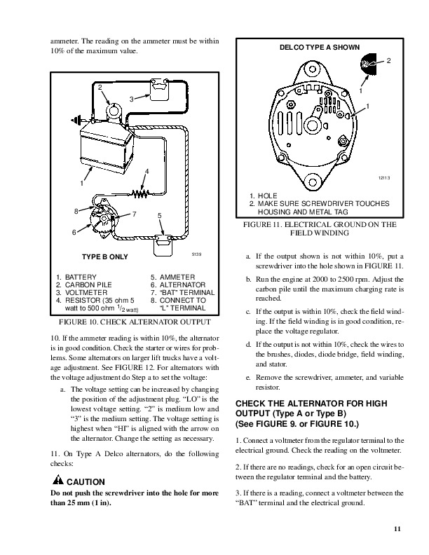
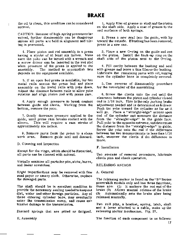
CHECK THE ALTERNATOR FOR LOW OUTPUT (Type A or Type B)…389
CHECK THE ALTERNATOR FOR HIGH OUTPUT (Type A or Type B)…390
CHECK THE CIRCUIT FOR THE BRUSHES…392
Delco Alternators…392
Motorola Alternators…392
CHECK THE DIODES…392
CHECK THE DIODE BRIDGE…392
Delco and Leece–Neville Alternators…392
Motorola Alternators…392
CHECK THE FIELD WINDING FOR THE ROTOR…393
CHECK THE WINDINGS IN THE STATOR…393
CHECK THE VOLTAGE REGULATOR…394
TROUBLESHOOTING…394
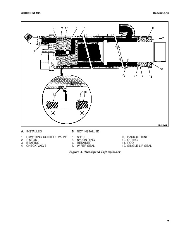
4000135…395
SAFETY PROCEDURES WHEN WORKING NEAR THE MAST…395
SAFETY PROCEDURES WHEN WORKING NEAR THE MAST…395
LIFT CYLINDERS…398
GENERAL…398
DESCRIPTION…398
Lowering Control Valve…398
Cylinders (General)…401
Cylinders (H520-620B,H700-800A)…403
Cylinders (H360-460B)…404
Cylinders (Two-Speed)…404
REPAIRS…405
REMOVAL OF THE LIFT CYLINDER WITHOUT REMOVING THE MAST…405
Standard Masts with the Main Lift Cylinder Fastened to the Crossmember of the Inner Mast…405
Standard and Full Free-Lift Masts with the Lift Cylinder to a Crosshead…409
Masts that have Two Cylinders, A Main Lift Cylinder and a Free-Lift Cylinder…407
DISASSEMBLY…407
ASSEMBLY…409
INSTALLATION OF THE LIFT CYLINDER IN THE MAST…409
Standard Masts with the Main Lift Cylinder Fastened to the Crossmember of the Inner Mast…409
Standard and Full-Free-Lift Masts with the Lift Cylinder Fastened to a Crosshead…409
CHEVRON PACKING…410
LIFT CYLINDERS FOR VISTA MASTS…413
DESCRIPTION…413
Lowering Control Valve…415
REMOVAL…416
DISASSEMBLY…416
ASSEMBLY…416
INSTALLATION…417
Main Lift Cylinders…417
Free-Lift Cylinders…417
CHECKS AND ADJUSTMENTS…418
CHECK FOR LEAKS IN LIFT SYSTEM…418
TROUBLESHOOTING…419
SPECIFICATIONS…420
4000268…421
INTRODUCTION…421
GENERAL…421
DESCRIPTION AND OPERATION…421
General…421
Lifting – High Speed…421
Lifting – Low Speed…422
Lowering…423
REPAIRS…423
FORKS…423
Removal…423
Low Mount Forks…423
Hight Mount Forks…423
Installation…423
Low Mount Forks…423
High Mount Forks…424
CARRIAGE…424
Removal…424
Disassembly…426
Cleaning and Inspection…427
Assembly…427
Installation…430
MAST…430
Removal…430
Disassembly…431
Cleaning and Inspection…433
Assembly…433
Installation…434
LIFT CYLINDERS…435
Removal…435
Disassembly…435
Cleaning and Inspection…435
Assembly…435
Installation…436
SIDE-SHIFT CYLINDER…436
Removal…436
Disassembly…436
Cleaning and Inspection…437
Assembly…437
Installation…437
FORK POSITIONER CYLINDERS…437
Removal…437
Disassembly…437
Cleaning and Inspection…437
Assembly…437
Installation…438
SLEW CYLINDERS…438
Removal…438
Disassembly…438
Assembly…438
Installation…438
ATTACHMENT CONNECTOR…438
HEADER HOSES…439
Replacement…439
CHECKS AND ADJUSTMENTS…440
ADJUST THE SIDE ROLLERS ON THE CARRIAGE…440
ADJUST THE SIDE ROLLERS ON THE MAST…440
ADJUST THE LIFT CHAINS…440
5000265…442
INTRODUCTION…442
GENERAL…442
DESCRIPTION…442
OPERATION…442
Extend And Retract Circuit…442
Twist Lock Circuit…443
Slew Circuit…444
REPAIRS…446
CONTAINER ATTACHMENT…446
Removal…446
Installation…446
HYDRAULIC VALVES…446
Removal…446
Disassembly…447
Cleaning And Inspection…447
Assembly…448
Installation…449
FORK ROLLERS…449
Removal and Disassembly…449
Ceaning and Inspection…450
Assembly and Installation…450
SLEW CYLINDERS…450
Removal…450
Disassembly…450
Assembly…450
Installation…451
BOOM SECTIONS…451
Disassembly…451
Cleaning and Inspection…451
Assembly…452
TWIST LOCKS…455
Disassembly…455
Assembly…455
CHECKS AND ADJUSTMENTS…460
ADJUST THE WIDTH OF THE ATTACHMENT…460
CHECK THE PRESSURE OF THE RELIEF VALVES…462
TROUBLESHOOTING…463
5000266…465
INTRODUCTION…465
GENERAL…465
DESCRIPTION…465
OPERATION…465
Slew Circuit…468
Twist Lock Circuit…465
REPAIRS…469
CONTAINER ATTACHMENT…469
Removal …469
Installation…469
HYDRAULIC VALVES…469
Disassembly…469
Cleaning and Inspection…469
Assembly…469
Installation…469
FORK ROLLERS…472
Removal and Disassembly…472
Cleaning and Inspection…472
Removal…472
Assembly and Installation…472
SLEW CYLINDERS…472
Removal…472
Disassembly…472
Assembly…472
Installation…472
TWIST LOCKS…473
Disassembly…473
Assembly…474
CHECKS AND ADJUSTMENTS…479
CHECK THE PRESSURE OF THE RELIEF VALVES…479
TROUBLESHOOTING…480
600269…482
INTRODUCTION…482
General…482
Description…482
CYLINDER HEAD AND VALVE MECHANISM…482
Cylinder Head…482
Valve Mechanism…484
LUBRICATION SYSTEM…487
Oil Pump…487
Idler Gear for the Oil Pump…488
Relief Valve for Oil Pressure…488
Relief Valve for Cold Oil…489
Oil Cooler…489
Control Valve for the Piston Cooling Jets…490
Piston Cooling Jets…490
TIMING GEARS AND CAMSHAFT…491
Timing Gear Case…491
Camshaft Gear…491
Camshaft…492
Camshaft Idler Gear…492
CRANKSHAFT…493
Removal…493
Repair…494
Installation…494
PISTON AND CONNECTING RODS…496
Removal…496
Repairs…496
Installation…497
CYLINDER LINERS…499
Removal and Installation…499
FLYWHEEL AND FLYWHEEL HOUSING…500
Removal…500
Repairs…500
Installation…500
FUEL SYSTEM…501
Fuel Pump…501
Fuel Injection Pump…502
Fuel Injectors…503
TURBOCHARGER…503
Removal…503
Disassembly…503
Cleaning and Inspection…504
Assembly…504
COOLING SYSTEM…505
Water Pump…505
AIR COMPRESSOR…506
Removal…506
Disassembly…506
Inspection…507
Assembly…507
Installation…508
CHECKS AND ADJUSTMENTS…508
Removing Air from the Fuel System…508
Timing the Fuel Injection Pump…509
Adjusting the Clearance of the Valves…510
Adjusting the Idle Speed…511
Adjusting the Stall Device…511
TROUBLESHOOTING…512
SPECIFICATIONS…513
700626…518
COOLING SYSTEM…518
INTRODUCTION…518
DESCRIPTION…518
RADIATOR…518
RADIATOR CAP…518
THERMOSTAT…518
WATER PUMP…519
FAN AND FAN SHROUD …519
REPAIRS…519
COOLING SYSTEM CHECKS…519
Exhaust Leaks…519
RADIATOR…519
Checks…519
Cleaning The Radiator…519
Drain The Cooling System…521
Fill The Cooling System…521
WATER PUMP…521
Checks…521
THERMOSTAT…522
Checks…522
FAN AND FAN SHROUD …522
TROUBLESHOOTING…523
8000231…524
INTRODUCTION…524
NOMENCLATURE, THREADS…524
STRENGTH IDENTIFICATION…525
TABLE 1. BOLTS AND SCREWS…525
TABLE 2. STUDS AND NUTS…526
TABLE 3. TORQUE NUTS…527
TABLE 4. TORQUE NUTS WITH NYLON INSERT…528
TABLE 5. TORQUE VALUES FOR INCH FASTENERS…529
TABLE 6. TORQUE VALUES FOR METRIC FASTENERS…530
8000271…533
INTRODUCTION…533
General…533
Maintenance Schedule…533
MAINTENANCE PROCEDURES…536
Every 8 Hours or Daily…536
Checks With The Engine Stopped…536
Checks With The Engine Running…539
Every 150 Hours or Monthly…541
Every 350 Hours or Monthly…544
Every 2000 Hours or Yearly…545
8000276…550
FIGURE 1. HYDRAULIC SYSTEM SCHEMATIC EARLY MODEL H16.00-30.00C (H360-650C)…550
FIGURE 2. HYDRAULIC SYSTEM SCHEMATIC LATE MODEL H17.00-32.00C (H370-700C)…552
FIGURE 3. ELECTRICAL SYSTEM SCHEMATIC EARLY MODEL H16.00-30.00C (H360-650C)…554
FIGURE 4. ELECTRICAL SYSTEM SCHEMATIC LATE MODEL H17.00-32.00C (H370-700C)…556
FIGURE 5. ELECTRICAL SYSTEM SCHEMATIC U.S. LIGHT SYSTEM…558
FIGURE 6. ELETRICAL SYSTEM SCHEMATIC EUROPEAN LIGHT SYSTEM…559
FIGURE 7. ELECTRICAL SYSTEM SCHEMATIC CAB…560
FIGURE 8. ELECTRICAL SYSTEM SCHEMATIC CONTAINER ATTACHMENT…561
8000277…562
8000440…568
INTRODUCTION…568
General…568
Welding Repairs…568
How to Move a Disabled Lift Truck…568
How to Put a Lift Truck on Blocks…569
MAINTENANCE SCHEDULE…570
MAINTENANCE PROCEDURES…573
EVERY 8 HOURS OR DAILY…573
How To Make Checks with the Engine Stopped…573
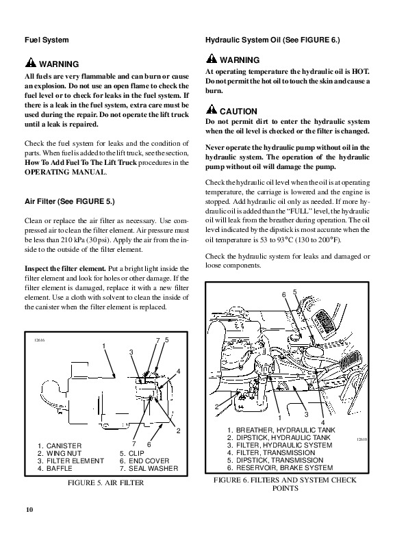
Hydraulic Sytem Oil…573
Air Filter…574
Engine Oil…574
Battery…574
Cooling System…575
Fuel System…575
Drive Belts…575
Upright, Forks and Lift Chains…575
Tires and Wheels…577
Operator Restraint System…578
How To Make Checks With The Engine Running…578
Guages, Lights, Horn, Fuses, Control Levers and Pedals…579
Transmission Oil…579
Lift System Operation…579
Attachment…579
Hydraulic Oil Filters…579
Brakes…580
Steering System…580
EVERY 150 HOURS OR MONTHLY…580
Engine Oil and Filters…580
Fuel Filters…580
Drive Shafts…580
Steering Axle…580
Brake Fluid Reservoir…580
Shafts for Brake Actuators…581
Brake Actuator Arms…581
Air Tanks…581
Upright…581
Lift Chains…581
Wheel Nuts…582
Steer Wheel Hubs…582
Drive Axle and Differential…582
Hydraulic Tank Breather…583
Container Attachments…583
EVERY 350 HOURS OR TWO MONTHS…583
Upright Pivots…583
Fork Pins and Fork Guides…583
Forks…583
Lift Chains…583
Drive Belts…584
Other Lubrication…584
Fuel Sytem…584
EVERY 500 HOURS…585
Transmission Oil Filter…585
EVERY 1000 HOURS…585
Transmission oil…585
EVERY 2000 HOURS OR YEARLY…585
Hydraulic System…585
Differential and Drive Axle…585
Drive Wheel Bearings…586
Service Brakes…586
GENERAL PROCEDURES…586
Check the Lift and Tilt System…586
Remove Air From The Perkins Diesel Fuel System…587
REPAIR OF TIRES AND WHEELS…588
Remove Wheels from the Lift Truck…588
Remove the Wheel from the Tire…589
Install the Wheel in the Tire…589
Add Air to the Tires…590
Install the Wheels…591
8000446…593
C008 (H360-700C)…599
100267…601
INTRODUCTION…601
GENERAL…601
DESCRIPTION…601
REPAIRS…601
COUNTERWEIGHT…601
Removal…601
Installation…601
FENDERS…601
Installation…602
HOOD AND BALLAST COVER…602
HYDRAULIC TANK…602
Removal, H16.00-32.00C (H360-650, H370-700C)…602
Removal, H46.00-44.00B (H700-920B)…603
Repairs, All Units…603
Steam Method of Cleaning…603
Chemical Solution Method of Cleaning…604
Other Methods Of Preparation For Repair…604
Installation, H16.00-32.00C (H360-650C, H370-700C)…604
Installation, H36.00-44.00B (H700-920B)…604
FUEL TANK…604
Removal, H16.00-32.00C (H360-650C, H370-700C)…604
Removal, H36.00-44.00B (H700-920B)…604
Repair, All Units…604
Installation, H16.00-32.00C (H360-650C, H370-700C)…604
Installation, H36.00-44.00B (H700-920B)…605
RADIATOR…605
Removal, H16.00-32.00C (H360-650C, H370-700C)…605
Removal, H36.00-44.00B (H700-920B)…605
Installation, H16.00-32.00C (H360-650C, H370-700C)…605
Installation, H36.00-44.00B (H700-920B)…605
ENGINE…605
Removal, H16.00-32.00C (H360-650C, H370-700C)…605
Installation, H16.00-32.00C (H360-650C, H370-700C)…606
Removal, H36.00-44.00B (H700-920B)…606
Installation, H36.00-44.00B (H700-920B)…607
OPERATOR'S COMPARTMENT AND CAB (See FIGURE 2.)…607
General…607
Removal…608
Repairs…610
Installation…611
LABEL REPLACEMENT…613
130017…615
INTRODUCTION…615
General…615
MECHANICAL DESCRIPTION…615
General…615
Torque Converter…615
Description…615
Operation…616
Clutch Assemblies…617
Description…617
Operation…618
First Stage Shaft…618
Second Stage Shaft…619
Third Stage Shaft…620
Inching Clutch…621
HYDRAULIC OPERATION…622
Sump, Filter and Pump…622
Control Valve, H360-620B…623
Control Valve, H360-650C…625
Inching Valve…627
Description…627
Operation…627
TRANSMISSION CONTROL CIRCUIT, H360-650C…630
HYDRAULIC CIRCUITS…630
Cooling and Lubrication…630
NEUTRAL-FIRST, H360-620B…630
NEUTRAL, H360-650C…632
FORWARD-FIRST, H360-620B…632
FORWARD-FIRST, H360-650C…634
REVERSE-FIRST, H360-620B…636
REVERSE-FIRST, H360-650C…637
SHIFT FROM FIRST TO SECOND SPEED, H360-620B…637
SHIFT FROM FIRST TO SECOND SPEED, H360-650C…637
1300171…639
INTRODUCTION…639
General…639
TRANSMISSION…639
Removal…639
Disassembly…640
Cleaning and Inspection…650
Assembly…650
Installation…664
TORQUE CONVERTOR…666
Removal and Disassembly…666
Cleaning and Inspection…668
Assembly and Installation…668
INCHING CLUTCH…671
Removal and Disassembly…671
Cleaning and Inspection…673
Assembly and Inspection…673
CONTROL VALVE…677
Removal…677
Disassembly…677
Cleaning and Inspection…678
Assembly…678
INCHING VALVE…679
Removal…679
Disassembly…679
Cleaning…679
Assembly…679
Installation…680
OIL PUMP…681
Removal…681
Disassembly…681
Cleaning and Inspection…682
Assembly…682
Installation…683
RANGE SELECTOR ASSEMBLY, H360-650C…683
Removal and Disassembly…683
Assembly and Installation…685
1300375…697
INTRODUCTION…697
General…697
MECHANICAL DESCRIPTION…698
General…698
Torque Converter…698
Description…698
Operation…699
Clutch Assemblies…699
Description…699
Operation…700
Forward Shaft…701
Reverse Shaft…701
First Speed Shaft…701
Output Shaft…701
HYDRAULIC OPERATION…702
Sump, Filter And Operation…702
Shift Control Valve…704
Solenoid Valves…704
Inching Spool…704
Direction Spools…704
Range Spools…704
Modulator Valve And Manifold Block…705
Operation…706
Transmission Control System, H17.00-32.00C(H370-700C)…708
Transmission Control System, H20.00-32.00F(H440-700F)…709
Hydraulic Circuits…711
Cooling and Lubrication…711
Operation Of The Transmission, NEUTRAL…712
Operation Of The Transmission, FORWARD-FIRST…713
Operation Of The Transmission, REVERSE-FIRST…714
Operation Of The Transmission, FORWARD-SECOND…715
Operation Of The Transmission, FORWARD-THIRD-INCHING…716
1300376…717
INTRODUCTION…717
General…717
Transmission…717
Removal…717
Transmission, Disassembly…719
Cleaning…735
Inspection…735
Transmission, Assembly…738
Installation…757
Modulator Valve And Manifold Block…761
Removal…761
Disassembly…761
Cleaning And Inspection…761
Assembly…762
Installation…762
Shift Control Valve…763
Removal…763
Disassembly…763
Cleaning And Inspection…764
Assembly…764
Installation…764
Oil Pump…765
Removal…765
Disassembly…765
Cleaning And Inspection…766
Assembly And Installation…766
Transmission Control Assembly H17.00-32.00C (H360-700C)…767
Removal And Disassembly…767
Assembly And Installation…768
Transmission Control Assembly H20.00-32.00 (H440-700F/FS)…769
Removal And Disassembly…769
Assembly And Installation…771
CHECKS AND ADJUSTMENTS…771
Check The Stall Speed Of The Torque Converter…771
Check The Oil Pressure Of The Transmission…772
TROUBLESHOOTING…773
140046…775
General…777
Description…777
Differential Repair…777
Remove…777
Disassemble…777
Assemble…777
Pinion, Bearings, and Pinion Carrier, Assemble…777
Pinion Bearings, Adjust Preload…779
Pinion Carrier Shim Set, Adjust Thickness (Depth of Pinion)…779
Differential and Ring Gear, Assemble…781
Differential Pinion and Side Gear Assembly, Assemble…783
Differential Gears Rotating Torque, Check…784
Differential and Ring Gear Assembly, Install…785
Differential Bearings, Preload Adjust…786
Ring Gear, Runout Check…786
Gear Clearance, Adjust…787
Gear Set, Tooth Contact Pattern Check…787
Install into Axle Housing…787
Specifications…790
General Specifications…790
Rivet Installation Pressure…790
Pinion Preload Pressure…790
Pinion Adjustment…790
Troubleshooting…793
160071…795
INTRODUCTION…795
GENERAL …795
DESCRIPTION…795
REPAIRS…796
STEERING AXLE…796
Removal…796
Installation…796
STEERING CYLINDER…796
Removal…796
Inspection…798
Assembly…798
Installation…798
HUBS, H7.00-12.50H (H150-275H), H13.50-16.00B (H300-350B), P7.00-9.00B (P150-200B)…799
Removal…799
Installation…799
HUBS, H360-620B, H16.00-30.00C, H17.00-32.00C, H700-800A, H36.00-44.00B, H36.00-48.00C, H20.00-32.00F…800
Removal…800
Installation…800
SPINDLES…800
Removal…800
Installation…800
CHECKS AND ADJUSTMENTS…802
REMOVE THE AIR FROM THE STEERING SYSTEM…802
ADJUST THE CYLINDER STOPS…802
1800273…803
INTRODUCTION…803
GENERAL…803
DESCRIPTION…803
OPERATION…805
Service Brakes…805
Parking Brake…805
REPAIRS…806
AIR TANKS…806
Relief Valve…806
Drain Valve…806
BRAKE PEDAL VALVE…807
Removal…807
Disassembly and Repair…807
Assembly…807
Installation…807
PARKING BRAKE VALVE…807
Removal…807
Disassembly and Repair…808
Assembly…808
Installation…808
AIR CHAMBERS…808
Removal…808
Disassembly…809
Inspection…810
Assembly…810
Installation…811
ACTUATOR ARMS…811
Removal…811
Installation…811
BRAKE SHOES…811
Removal…812
Cleaning…812
Repair…813
Installation…813
BRAKE DRUMS (SERVICE BRAKES)…813
DISC BRAKE ASSEMBLY (SERVICE BRAKES)…813
Brake Pads Replacement…813
Brake Caliper, Removal…814
Brake Caliper, Disassembly…814
Brake Caliper, Repair…815
Brake Caliper, Assembly…815
Brake Caliper, Installation…815
Brake Rotor, Removal…815
Brake Rotor, Installation…815
Brake Booster, Removal…815
Brake Booster, Disassembly…815
Brake Booster, Inspection…815
Brake Booster, Assembly…816
Brake Booster, Installation…816
DISC BRAKE ASSEMBLY (PARKING BRAKE)…816
Brake Pads, Replacement…816
Brake Caliper, Removal And Disassembly…817
Brake Caliper, Cleaning…817
Air Chamber, Service…818
CHECKS AND ADJUSTMENTS…818
REMOVING AIR FROM THE BRAKE SYSTEM…818
CHECK AND ADJUST THE GOVERNOR FOR THE AIR COMPRESSOR…818
ADJUSTMENT OF THE BRAKE SHOES…819
CHECK WEAR ADJUSTMENT FOR THE PARKING BRAKE…819
TROUBLESHOOTING…820
1800425…822
INTRODUCTION…822
GENERAL…822
DESCRIPTION…822
H26.00-32.00C (H550-700C)…822
H36.00-44.00B (H700-920B), H36.00-48.00C (H800-1050C)…822
OPERATION…822
Service Brakes, H26.00-32.00C (H550-700C)…822
Service Brakes, H36.00-44.00B (H700-920B), H36.00-48.00C (H800-1050C)…826
Parking Brake, H26.00-32.00C (H550-700C)…826
Parking Brake, H36.00-44.00B (H700-920B), H36.00-48.00C (H800-1050C)…827
REPAIRS…828
AIR TANKS…828
Relief Valve…828
Drain Valve…828
BRAKE PEDAL VALVES…828
Removal…828
Disassembly and Repair…829
Assembly…829
Installation…829
PARKING BRAKE VALVE…830
Removal…830
Disassembly and Repair…830
Assembly…830
Installation…831
PARKING BRAKE ACTUATOR, H26.00-32.00C (H550-700C)…831
Removal…831
Disassembly…831
Inspection…832
Assembly…832
Installation…832
PARKING BRAKE ACTUATOR, H36.00-44.00B (H700-920B), H36.00-48.00C (H800-1050C)…832
Removal…832
Disassembly…832
Inspection…833
Assembly…833
Installation…834
PARKING BRAKE ASSEMBLY…834
Removal and Installation…834
Cleaning…834
Inspection…834
Assembly and Installation…834
SERVICE BRAKE ACTUATORS…835
Removal…835
Disassembly…835
Cleaning and Inspection…835
Assembly…835
Installation…835
BRAKE CALIPERS…836
Removal…836
Disassembly…837
Cleaning…837
Inspection…838
Assembly…838
Installation…839
INCHING VALVE ACTUATOR, H36.00-44.00B (H700-920B)…839
Removal…840
Disassembly…840
Cleaning and Inspection…840
Assembly…840
Installation…840
CHECKS AND ADJUSTMENTS…841
REMOVE THE AIR FROM THE BRAKE SYSTEM…841
INCHING ADJUSTMENT…841
CHECK AND ADJUST THE GOVERNOR FOR THE AIR COMPRESSOR…841
CHECK AND ADJUST THE PRESSURE REGULATORS FOR THE PARKING BRAKE, H36.00-44.00B (H700-920B), H36.00-48.00C (H800-1050C)…841
TROUBLESHOOTING…843
1900253…845
INTRODUCTION H16.00-30.00C (H360-650C), H17.00-32.00C (H370-700C)…845
GENERAL…845
DESCRIPTION AND OPERATION…845
Right-Hand Hydraulic Pump…845
Left-Hand Hydraulic Pump…845
Auxiliary Hydraulic Pump (Left-Hand)…845
Auxiliary Hydraulic Pump (Right-Hand)…845
Main Control Valve…847
Attachment Control Valve…847
Remote Control Valve…847
Pressure Reduction Valve…847
Solenoid Valves…847
Steering Control Unit…847
INTRODUCTION H36.00-44.00B (H700-920B)…853
GENERAL…853
DESCRIPTION AND OPERATION…853
Main Control Valve…853
Attachment Control Valve…853
Remote Control Valve…853
Pressure Reduction Valve…853
Solenoid Valves…854
Steering Control Unit…855
TROUBLESHOOTING…860
SPECIFICATIONS H16.00-30.00C (H360-650C), H17.00-32.00C (H370-700C)…863
SPECIFICATIONS H36.00-44.00B (H700-920B)…864
190097…865
INTRODUCTION…865
DESCRIPTION…865
OPERATION…865
Flow Control Valve…867
Relief Valve…867
REPAIRS…868
REMOVAL…868
DISASSEMBLY…868
CLEANING…870
INSPECTION…870
ASSEMBLY…871
INSTALLATION…872
CHECKS AND ADUSTMENTS…873
CHECK THE OUTPUT OF THE PUMP…873
CHECK FOR AIR IN THE HYDRAULIC SYSTEM…873
TROUBLESHOOTING…875
2000249…878
INTRODUCTION…878
GENERAL…878
DESCRIPTION…878
OPERATION…878
REPAIRS…881
REMOVAL…881
DISASSEMBLY…881
INSPECTION…882
ASSEMBLY…882
INSTALLATION…884
ADJUSTMENT…885
TROUBLESHOOTING…885
2000250…886
INTRODUCTION…886
GENERAL…886
DESCRIPTION…886
OPERATION…886
Lift Circuit, High Speed (Light Load or No Load)…886
Lift Circuit, Normal Speed (Heavy Load)…887
Lowering…888
Two Speed Spool…889
Tilt Circuit…889
Relief Valve…890
REPAIRS…891
REMOVAL…891
DISASSEMBLY…891
CLEANING AND INSPECTION…891
ASSEMBLY…891
INSTALLATION…892
CHECKS AND ADJUSTMENTS…892
CHECKING THE RELIEF PRESSURE…892
CHECKING THE PRESSURE OF THE TWO SPEED CARTRIDGE…892
TROUBLESHOOTING…893
2000251…895
INTRODUCTION…895
GENERAL…895
DESCRIPTION…895
OPERATION…895
REPAIRS…896
REMOVAL…896
DISASSEMBLY…896
CLEANING AND INSPECTION…896
ASSEMBLY…897
INSTALLATION…897
CHECKS AND ADJUSTMENTS…898
CHECK AND ADJUST THE RELIEF VALVE…898
TROUBLESHOOTING…899
2000252…900
INTRODUCTION…900
GENERAL…900
DESCRIPTION AND OPERATION…900
FLOW REGULATORS…900
RELIEF VALVE…901
PRESSURE REDUCTION VALVE…901
TWIST LOCK SOLENOID VALVE…903
LOCK OUT SOLENOID VALVE…903
REPAIRS…904
FLOW REGULATORS…904
Removal…904
Disassembly…904
Cleaning and Inspection…904
Assembly…904
Installation…904
RELIEF VALVE…904
PRESSURE REDUCTION VALVE…904
TWIST LOCK SOLENOID VALVE AND LOCK OUT SOLENOID VALVE…904
CHECKS AND ADJUSTMENTS…905
CHECK THE CONTROLLED FLOW OF THE FLOW REGULATORS…905
CHECK AND ADJUST THE RELIEF VALVE (STEERING SYSTEM)…905
CHECK THE PRESSURE REDUCTION VALVE…906
TROUBLESHOOTING…907
2100102…909
INTRODUCTION…909
GENERAL…909
DESCRIPTION AND OPERATION…909
Tilt Forward…909
Tilt Backward…910
REPAIRS…912
REMOVAL…912
DISASSEMBLY…912
CLEANING…912
ASSEMBLY…912
INSTILLATION…913
TROUBLESHOOTING…913
2100103…914
General…916
Description…916
Tilt Cylinder…916
Remove…916
Disassemble…916
Clean…916
Assemble…916
Tilt Cylinders with O-Ring or Single-Lip Seals…916
Tilt Cylinders for XM and XMS Models…918
Tilt Cylinders for H700-800A and Early Model H700-920B…919
Install…920
Tilt Cylinders Using Chevron Packing…921
Install…922
Tilt Cylinder Leak Check…924
Tilt Cylinder Stroke and Mast Tilt Angle Adjustment…925
Torque Specifications…925
Piston Rod Nut…925
Retainer…927
Troubleshooting…928
2200106…931
General…933
Description and Operation…933
Starter Repair…935
Remove…935
Disassemble…935
Clean…936
Assemble…936
Install…937
General Checks and Adjustments…937
Troubleshooting…940
2200143…944
INTRODUCTION…944
GENERAL…944
DESCRIPTION…944
GENERAL…944
STEERING COLUMN GAUGES, METERS AND INDICATORS…947
LED DISPLAY PANEL…947
Battery Discharge Indicators…947
Brush Wear Indicators…948
Motor Temperature Indicators…949
"LX" SERIES DISPLAY PANEL…950
Hourmeter Functions…951
Battery Indicator Function…951
Status Code Function…951
"ZX" SERIES DISPLAY PANELS…951
Display Panel…952
Basic Display Panels…952
Performance Display…954
Brush Wear Indicators…957
CHECKS AND ADJUSTMENTS…957
GENERAL…957
REPLACEMENT…958
GENERAL…958
METER REPLACEMENT…958
SENDER REPLACEMENT…959
Fuel Level Sender…959
Pressure And Temperature Sender…959
I.T.W. DISPLAY PANEL…960
Removal…960
DISPLAY PANELS FOR THE EV – 100/200ZX MOTOR CONTROLLERS, COLUMN MOUNT…961
Removal…961
Replacing Display Panel Assembly…961
Indicator LEDs…961
Battery Indicators…961
Digital Display (Performance Disply Panel Only)…961
Status Code Or Performance Level Switches And Indicator LEDs (Performance Display Panel Only)…961
Replacing Parts Of The Basic Display Panel…962
Replacing Parts Of The Performance Display Panel…964
DISPLAY PANELS FOR THE EV-100/200ZX MOTOR CONTROLLERS, DASH MOUNT…964
Removal And Replacement…964
SPECIFICATIONS…965
TROUBLESHOOTING…966
2200144…967
ELECTRICAL WARNING DEVICES…967
GENERAL…967
DESCRIPTION…967
Operator Controlled Horns…967
System Warning Lights, Buzzers and Bells…967
Reverse Warning Horns…968
Warning Lights…968
REPLACEMENT…969
General…969
Replacing Horns or Bells…969
Replacing Horn Relay or Buzzer…969
Replacing Warning Lights…969
Light Assemblies…970
Replacing Flashing Units…970
22002…971
General…973
Description…973
Alternator Repair…975
Alternator Type A…975
Remove and Disassemble…975
Clean…976
Assemble…976
Install…977
Alternator Type B…980
Remove and Disassemble…980
Clean…980
Assemble…981
Install…982
General Check and Adjustment…983
Low Output Check (Type A or Type B)…983
High Output Check (Type A or Type B)…985
Brushes Circuit Check…986
Delco Alternators…986
Motorola Alternators…987
Diodes Check…988
Diodes Bridge Check…988
Delco and Leece-Neville Alternators…988
Motorola Alternators…988
Rotor Field Winding Check…989
Stator Windings Check…990
Voltage Regulator Check…990
Troubleshooting…991
4000135…993
Safety Procedures When Working Near Mast…995
General…1000
Description…1000
Lowering Control Valve…1000
Cylinders (General)…1003
Cylinders (H520-620B, H700-800A)…1003
Retainer, Install…1003
Cylinders (H360-460B)…1005
Cylinders (Two-Speed)…1008
Lift Cylinder Repair…1009
Lift Cylinder Removal Without Removing Mast…1009
Standard Masts With Main Lift Cylinders Fastened to Crossmember of Inner Mast…1009
Standard and Full Free-Lift Masts With Lift Cylinder Fastened to Crosshead…1010
Masts That Have Two Cylinders, Main Lift Cylinder and Free-Lift Cylinder…1011
Disasemble…1011
Assemble…1011
Lift Cylinder Installation in Mast…1013
Standard Masts With Main Lift Cylinder Fastened to Crossmember of Inner Mast…1013
Standard and Full Free-Lift Masts With Lift Cylinder Fastened to Crosshead…1013
Chevron-Style Packing…1013
Chevron-Style Packing Installation on Piston…1014
Chevron-Style Packing Installation in Packing Gland…1016
Lift Cylinders for Vista Masts…1017
Description…1017
Lowering Control Valve…1017
Remove…1019
Disassemble…1020
Assemble…1021
Install…1022
Main Lift Cylinders…1022
Free-Lift Cylinder…1022
Lift System Leak Check…1022
Specifications…1023
Troubleshooting…1024
4000268…1027
INTRODUCTION…1027
GENERAL…1027
DESCRIPTION AND OPERATION…1027
General…1027
Lifting – High Speed…1027
Lifting – Low Speed…1028
Lowering…1029
REPAIRS…1029
FORKS…1029
Removal…1029
Low Mount Forks…1029
Hight Mount Forks…1029
Installation…1029
Low Mount Forks…1029
High Mount Forks…1030
CARRIAGE…1030
Removal…1030
Disassembly…1032
Cleaning and Inspection…1033
Assembly…1033
Installation…1036
MAST…1036
Removal…1036
Disassembly…1037
Cleaning and Inspection…1039
Assembly…1039
Installation…1040
LIFT CYLINDERS…1041
Removal…1041
Disassembly…1041
Cleaning and Inspection…1041
Assembly…1041
Installation…1042
SIDE-SHIFT CYLINDER…1042
Removal…1042
Disassembly…1042
Cleaning and Inspection…1043
Assembly…1043
Installation…1043
FORK POSITIONER CYLINDERS…1043
Removal…1043
Disassembly…1043
Cleaning and Inspection…1043
Assembly…1043
Installation…1044
SLEW CYLINDERS…1044
Removal…1044
Disassembly…1044
Assembly…1044
Installation…1044
ATTACHMENT CONNECTOR…1044
HEADER HOSES…1045
Replacement…1045
CHECKS AND ADJUSTMENTS…1046
ADJUST THE SIDE ROLLERS ON THE CARRIAGE…1046
ADJUST THE SIDE ROLLERS ON THE MAST…1046
ADJUST THE LIFT CHAINS…1046
5000265…1048
INTRODUCTION…1048
GENERAL…1048
DESCRIPTION…1048
OPERATION…1048
Extend And Retract Circuit…1048
Twist Lock Circuit…1049
Slew Circuit…1050
REPAIRS…1052
CONTAINER ATTACHMENT…1052
Removal…1052
Installation…1052
HYDRAULIC VALVES…1052
Removal…1052
Disassembly…1053
Cleaning And Inspection…1053
Assembly…1054
Installation…1055
FORK ROLLERS…1055
Removal and Disassembly…1055
Ceaning and Inspection…1056
Assembly and Installation…1056
SLEW CYLINDERS…1056
Removal…1056
Disassembly…1056
Assembly…1056
Installation…1057
BOOM SECTIONS…1057
Disassembly…1057
Cleaning and Inspection…1057
Assembly…1058
TWIST LOCKS…1061
Disassembly…1061
Assembly…1061
CHECKS AND ADJUSTMENTS…1066
ADJUST THE WIDTH OF THE ATTACHMENT…1066
CHECK THE PRESSURE OF THE RELIEF VALVES…1068
TROUBLESHOOTING…1069
5000266…1071
INTRODUCTION…1071
GENERAL…1071
DESCRIPTION…1071
OPERATION…1071
Slew Circuit…1074
Twist Lock Circuit…1071
REPAIRS…1075
CONTAINER ATTACHMENT…1075
Removal …1075
Installation…1075
HYDRAULIC VALVES…1075
Disassembly…1075
Cleaning and Inspection…1075
Assembly…1075
Installation…1075
FORK ROLLERS…1078
Removal and Disassembly…1078
Cleaning and Inspection…1078
Removal…1078
Assembly and Installation…1078
SLEW CYLINDERS…1078
Removal…1078
Disassembly…1078
Assembly…1078
Installation…1078
TWIST LOCKS…1079
Disassembly…1079
Assembly…1080
CHECKS AND ADJUSTMENTS…1085
CHECK THE PRESSURE OF THE RELIEF VALVES…1085
TROUBLESHOOTING…1086
600269…1088
INTRODUCTION…1088
General…1088
Description…1088
CYLINDER HEAD AND VALVE MECHANISM…1088
Cylinder Head…1088
Valve Mechanism…1090
LUBRICATION SYSTEM…1093
Oil Pump…1093
Idler Gear for the Oil Pump…1094
Relief Valve for Oil Pressure…1094
Relief Valve for Cold Oil…1095
Oil Cooler…1095
Control Valve for the Piston Cooling Jets…1096
Piston Cooling Jets…1096
TIMING GEARS AND CAMSHAFT…1097
Timing Gear Case…1097
Camshaft Gear…1097
Camshaft…1098
Camshaft Idler Gear…1098
CRANKSHAFT…1099
Removal…1099
Repair…1100
Installation…1100
PISTON AND CONNECTING RODS…1102
Removal…1102
Repairs…1102
Installation…1103
CYLINDER LINERS…1105
Removal and Installation…1105
FLYWHEEL AND FLYWHEEL HOUSING…1106
Removal…1106
Repairs…1106
Installation…1106
FUEL SYSTEM…1107
Fuel Pump…1107
Fuel Injection Pump…1108
Fuel Injectors…1109
TURBOCHARGER…1109
Removal…1109
Disassembly…1109
Cleaning and Inspection…1110
Assembly…1110
COOLING SYSTEM…1111
Water Pump…1111
AIR COMPRESSOR…1112
Removal…1112
Disassembly…1112
Inspection…1113
Assembly…1113
Installation…1114
CHECKS AND ADJUSTMENTS…1114
Removing Air from the Fuel System…1114
Timing the Fuel Injection Pump…1115
Adjusting the Clearance of the Valves…1116
Adjusting the Idle Speed…1117
Adjusting the Stall Device…1117
TROUBLESHOOTING…1118
SPECIFICATIONS…1119
700626…1124
General…1126
Description…1127
Radiator…1127
Radiator Cap…1127
Thermostat…1127
Water Pump…1128
Fan and Fan Shroud…1128
Cooling System Checks…1128
Radiator…1128
Thermostat…1128
Water Pump…1129
Exhaust Leaks…1129
Fan and Fan Shroud…1129
Radiator Cleaning…1129
Drain…1129
Clean…1129
Fill…1130
Troubleshooting…1131
8000231…1133
General…1135
Nomenclature, Threads…1135
Strength Identification…1136
Fastener Torque Tables…1140
Conversion Table…1142
8000271…1144
INTRODUCTION…1144
General…1144
Maintenance Schedule…1144
MAINTENANCE PROCEDURES…1147
Every 8 Hours or Daily…1147
Checks With The Engine Stopped…1147
Checks With The Engine Running…1150
Every 150 Hours or Monthly…1152
Every 350 Hours or Monthly…1155
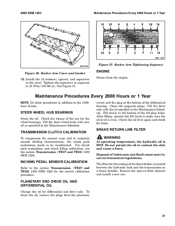
Every 2000 Hours or Yearly…1156
8000276…1161
FIGURE 1. HYDRAULIC SYSTEM SCHEMATIC EARLY MODEL H16.00-30.00C (H360-650C)…1161
FIGURE 2. HYDRAULIC SYSTEM SCHEMATIC LATE MODEL H17.00-32.00C (H370-700C)…1163
FIGURE 3. ELECTRICAL SYSTEM SCHEMATIC EARLY MODEL H16.00-30.00C (H360-650C)…1165
FIGURE 4. ELECTRICAL SYSTEM SCHEMATIC LATE MODEL H17.00-32.00C (H370-700C)…1167
FIGURE 5. ELECTRICAL SYSTEM SCHEMATIC U.S. LIGHT SYSTEM…1169
FIGURE 6. ELETRICAL SYSTEM SCHEMATIC EUROPEAN LIGHT SYSTEM…1170
FIGURE 7. ELECTRICAL SYSTEM SCHEMATIC CAB…1171
FIGURE 8. ELECTRICAL SYSTEM SCHEMATIC CONTAINER ATTACHMENT…1172
8000277…1173
8000440…1179
INTRODUCTION…1179
General…1179
Welding Repairs…1179
How to Move a Disabled Lift Truck…1179
How to Put a Lift Truck on Blocks…1180
MAINTENANCE SCHEDULE…1181
MAINTENANCE PROCEDURES…1184
EVERY 8 HOURS OR DAILY…1184
How To Make Checks with the Engine Stopped…1184
Hydraulic Sytem Oil…1184
Air Filter…1185
Engine Oil…1185
Battery…1185
Cooling System…1186
Fuel System…1186
Drive Belts…1186
Upright, Forks and Lift Chains…1186
Tires and Wheels…1188
Operator Restraint System…1189
How To Make Checks With The Engine Running…1189
Guages, Lights, Horn, Fuses, Control Levers and Pedals…1190
Transmission Oil…1190
Lift System Operation…1190
Attachment…1190
Hydraulic Oil Filters…1190
Brakes…1191
Steering System…1191
EVERY 150 HOURS OR MONTHLY…1191
Engine Oil and Filters…1191
Fuel Filters…1191
Drive Shafts…1191
Steering Axle…1191
Brake Fluid Reservoir…1191
Shafts for Brake Actuators…1192
Brake Actuator Arms…1192
Air Tanks…1192
Upright…1192
Lift Chains…1192
Wheel Nuts…1193
Steer Wheel Hubs…1193
Drive Axle and Differential…1193
Hydraulic Tank Breather…1194
Container Attachments…1194
EVERY 350 HOURS OR TWO MONTHS…1194
Upright Pivots…1194
Fork Pins and Fork Guides…1194
Forks…1194
Lift Chains…1194
Drive Belts…1195
Other Lubrication…1195
Fuel Sytem…1195
EVERY 500 HOURS…1196
Transmission Oil Filter…1196
EVERY 1000 HOURS…1196
Transmission oil…1196
EVERY 2000 HOURS OR YEARLY…1196
Hydraulic System…1196
Differential and Drive Axle…1196
Drive Wheel Bearings…1197
Service Brakes…1197
GENERAL PROCEDURES…1197
Check the Lift and Tilt System…1197
Remove Air From The Perkins Diesel Fuel System…1198
REPAIR OF TIRES AND WHEELS…1199
Remove Wheels from the Lift Truck…1199
Remove the Wheel from the Tire…1200
Install the Wheel in the Tire…1200
Add Air to the Tires…1201
Install the Wheels…1202
8000446…1204
myManual[2]…1210
INTRODUCTION…1210
General…1210
Description…1212
Operation…1212
REPAIRS…1213
Removal…1213
Disassembly…1213
Inspection…1218
Assembly…1218
Installation…1218
CHECKS AND ADJUSTMENTS…1224
TROUBLESHOOTING…1225
Hyster H360-650C (C008) & H370-700C (C008) Service Repair Manual