Complete service repair manual for B214 (H16.00-22.00XM-12EC Europe & H400-500HD-EC), with all the shop information to maintain, diagnose, repair, and rebuild like professional mechanics.
Hyster B214 (H16.00-22.00XM-12EC Europe & H400-500HD-EC) workshop service repair manual includes:
* Numbered table of contents easy to use so that you can find the information you need fast.
* Detailed sub-steps expand on repair procedure information
* Numbered instructions guide you through every repair procedure step by step.
* Troubleshooting and electrical service procedures are combined with detailed wiring diagrams for ease of use.
* Notes, cautions and warnings throughout each chapter pinpoint critical information.
* Bold figure number help you quickly match illustrations with instructions.
* Detailed illustrations, drawings and photos guide you through every procedure.
* Enlarged inset helps you identify and examine parts in detail.
Hyster B214 (H16.00-22.00XM-12EC Europe & H400-500HD-EC) Service Manual.pdf
Total Pages: 2,021 pages
File Format: PDF (Internal Links, Bookmarked, Table of Contents, Searchable, Printable, high quality)
Language: English
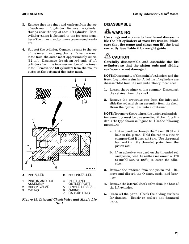
B214 (H16.00-22.00XM-12EC Europe)…2
1498450-1800SRM0951-(03-2007)-UK-EN…3
toc…3
Wet Brake System…3
Safety Precautions Maintenance and Repair…4
General…7
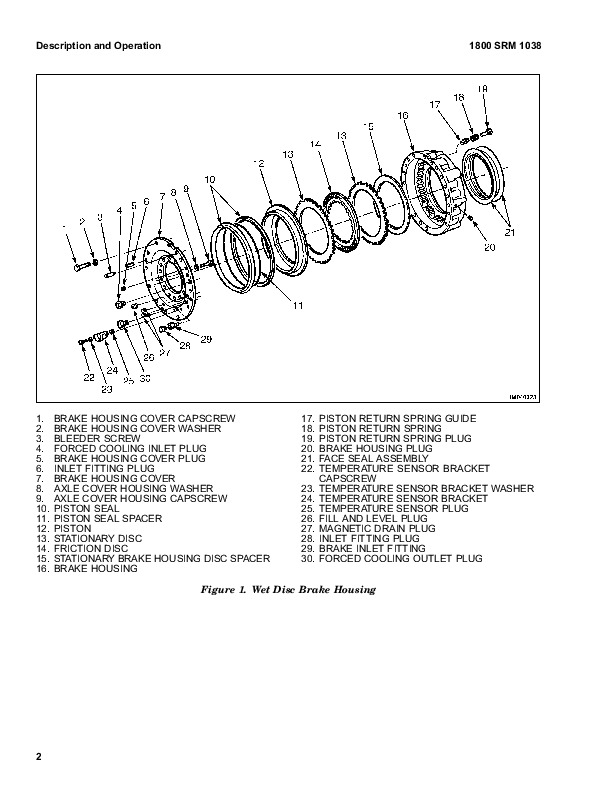
Description and Operation…7
Service Brakes…7
Parking Brake…7
Oil Cooler Circuit…7
Pressure Switch Replacement…11
Accumulators Replacement…11
Brake Treadle Valve Repair…11
Remove and Disassemble…11
Clean and Inspect…12
Assemble and Install…12
Parking Brake Valve Repair…12
Remove…12
Clean and Inspect…12
Repair…12
Install…12
Parking Brake Caliper Repair…13
Remove…13
Disassemble…15
Inspect…15
Install…15
Adjust…15
Brake Pad Repair…16
Inspect…16
Remove…16
Install…16
Seals Repair…16
Remove…16
Install…17
Service Brake Repair…17
Remove and Disassemble…17
Drain Lubricating Oil…17
Drain Coolant Oil…24
Disconnect Brake Lines…24
Wheel End With Outer Bearing on Ring Gear Hub Journal H13.00-14…24
Wheel End With Outer Bearing on Spindle Journal H8.00-12.00XM (H…25
Brake Disc Housing Assembly Wheel End…26
Brake Piston Housing…27
Brake Piston Housing and Wheel Spindle…28
Inspect…28
Clean…30
Assemble…31
Wheel Spindle…31
Brake Piston Housing…31
Piston Assembly…33
Brake Disc Housing…33
Duo-Cone Face Seal Into Brake Disc Housing and Into Hub…35
Check for Correct Installation of Duo-Cone Seal…36
Wheel Hub to Brake Disc Housing…37
Adjust…38
Fill Brake System With Coolant Oil…38
System Air Removal…39
Adjust Brake With New Disc Pack…39
Coolant Change Intervals…40
Coolant Draining and Filling…40
Specifications…42
Minimum Brake Disc Thickness…45
Hydraulic Fluid for Brake Actuation…45
Brake Coolant Specifications…45
Coolant Change Intervals…45
Hydraulic Fluid Specifications…45
Troubleshooting…45
Brake Does Not Apply…45
Brake Does Not Release…46
Brake Performance…46
Brake Leaks Actuation Fluid…47
Brake Cooling Fluid Leakage…48
Brake Noise and Vibration…48
Brake Overheats…48
tables…3
Table 1. Brake Pad Adjustment…15
Table 2. Minimum Brake Disc Thickness…29
Table 3. Formed Seal Wear Chart…29
1509204-5000SRM0990-(05-2006)-UK-EN…53
toc…53
Empty Container Handling Attachment…53
Safety Precautions Maintenance and Repair…54
General…57
Description…57
Operation…67
General…67
Selector Valves…67
Sideshift Circuit…67
Extend and Retract Circuit…67
Twist Lock Circuit and Control…67
Model 572 – Double Horizontally Mounted…67
Model 573 – Horizontally Mounted…68
Model 578 – Vertically Mounted…68
Lifting Hooks…68
Model 575…68
Indicator Lights and LEDs…68
Lift Interrupt and Override…69
Overlowering Interrupt and Override…69
Second Container Detection Sensor (Model 572 Only)…70
Carriage and Attachment Repair…70
Remove…70
Attachment Without Carriage Repair…71
Remove…71
Sideshift Cylinders Repair…71
Remove…71
Disassemble…71
Assemble…72
Extension Cylinders Repair…72
Remove…72
Disassemble…72
Clean and Inspect…73
Assemble…73
Install…73
Floating End Beams Repair…74
Remove…74
Install…74
Hose Replacement In End Beams…74
Twist Locks Repair for Model 572 and 573…74
Remove…74
Model 573…74
Model 572…74
Disassemble…75
Clean and Inspect…75
Assemble…75
Hook Replacement for Model 575…76
Inspect…76
Remove…76
Install…76
Twist Locks Repair for Model 578…77
Disassemble…77
Clean and Inspect…77
Assemble…77
Extension Beams Repair…78
LH and RH Extension Beam, Remove…78
Slave Beam, Remove…78
Clean and Inspect…79
Assemble…79
Bleed the System…80
Valve Assembly…80
Slide Pad Replacement…81
Adjustments…81
Twist Lock Angle Adjustment…81
Model 578 Only…81
LOCKED/NOT LOCKED Sensors Adjustment…82
Model 573…82
Model 578…82
Seated Sensor Adjustment…82
Model 572 and 573…82
Model 578…83
Overlowering Protection Sensor Adjustment (Models 572, 573, and …83
Torque Chart…84
Maintenance…84
Additional Attachment Maintenance…87
Interface Boxes With LED Indicators…88
Models 572, 573, 575, and 578: Interface Box With LED Indicators…88
Models 573 and 578: Two Additional Interface Boxes With LED Indi…88
Model 572…89
Troubleshooting…89
tables…53
Table 1. Torque Chart…84
Table 2. Maintenance Schedule…85
1529749-1800SRM1036-(07-2007)-UK-EN…119
toc…119
Brake Accumulator…119
Safety Precautions Maintenance and Repair…120
General…123
Description and Operation…123
Accumulator Maintenance…123
Precharge Check…123
Precharge Filling…124
Remove…125
Disassemble…125
Clean…127
Inspect…127
Repair…127
Assemble…127
Replace…127
tables…119
Table 1. Accumulator Pressures…124
1564053-0600SRM1101-(11-2007)-UK-EN…131
toc…131
Cummins Diesel/LPG Engine Fault Code Guide…131
Safety Precautions Maintenance and Repair…132
General…135
Fault Codes…135
Normal Mode…135
Fault Log Mode…135
Access…135
Exit…136
Clear…136
Electronic Throttle Calibration…136
Electronic Throttle Calibration Procedure…136
tables…131
Table 1. Error Code Descriptions…137
1565789-1800SRM1117-(07-2007)-UK-EN…153
toc…153
Parking Brake…153
Safety Precautions Maintenance and Repair…154
General…157
Description and Operation…157
Parking Brake Valve Replacement…157
Remove…157
Clean and Inspect…158
Install…158
Parking Brake Caliper Repair…158
Remove…158
Disassemble…158
Inspect…158
Install…159
Bleed Brakes…161
Adjust…161
Brake Pad Repair…162
Inspect…162
Remove…162
Install…163
Seals Repair…163
Remove…163
Install…163
Specifications…164
Torque Requirements…164
Wear Limits…164
Lining to Disc Clearance…164
Troubleshooting…165
tables…153
Table 1. Brake Pad Adjustment…162
Table 2. Torque Requirements…164
Table 3. Wear Limits…164
Table 4. Lining to Disc Clearance…164
1612615-5000SRM1221-(11-2006)-UK-EN…169
toc…169
Extendable Container Attachment (Elme)…169
Safety Precautions Maintenance and Repair…170
General…175
Description…175
Operation…179
General…179
Optional Powered Pile Slope…179
Sideshift…180
Extend and Retract Circuit…181
Container locking Model 582…183
Sequence Valve…183
Pilot Check Valve…184
Container Locking Model 583…185
Container Locking Model 584…185
Container Locking Model 585…186
Container Locking Models 586, 588, and 589…186
Electrical System…188
Indicator Lights…188
Flashing Indicator Lights…189
Automatic Locking…189
Lift Interrupt and Override…189
Overlowering Interrupt and Override…189
Second Container Detection Sensor (Model 582 Only)…190
Carriage and Attachment Removal…190
Carriage…190
Spreader…191
Sideshift Cylinder Removal and Installation…191
Remove…191
Install…191
Extension Cylinder Removal and Installation…192
Remove…192
Upper, Right-Hand…192
Lower, Left-Hand…192
Install…192
Floating End Beams Repair…193
Remove…193
Install…193
Hose, Replace…194
Twist Lock Repair for Model 582…195
Remove…195
Upper Twist Lock…195
Lower Twist Lock…195
Disassemble…196
Clean and Inspect…196
Assemble…197
Install…197
Hook Repair for Model 584 and 585…197
Remove…197
Inspect…197
Install…197
Side Clamp Replacement for Model 584…198
Remove…198
Install…199
Twist Lock Repair for Models 586, 588, and 589…199
Disassemble…199
Clean and Inspect…199
Assemble…200
Extension Beam Repair…201
Remove…201
Inspect…201
Assemble…202
Cylinder Repair…203
Extension Cylinder…203
Disassemble…203
Clean and Inspect…203
Assemble…203
Guide for Extension Cylinder…204
Remove…204
Install…204
Sideshift Cylinder, Powered Pile Slope Cylinder, Retract Cylinde…204
Disassemble…204
Assemble…204
Wear Pad Replacement…205
General…205
Floating End Beam Wear Pads…205
Upper Wear Pads…205
Lower Wear Pads…205
Main Frame Wear Pads at Large (Right-Hand) Extension Beam…205
Main Frame Wear Pads at Small (Left-Hand) Extension Beam…205
Guide for Extension Cylinder…206
Large Extension Beam Internal Wear Pads…207
Spreader Frame…207
Upper Wear Pads…207
Lower Wear Pads…207
Powered Pile Slope Carriage…207
Upper Wear Pads…207
Lower Wear Pads…207
Adjustments…207
Twist Lock Angle Adjustment…207
Model 586, 588 and 589…207
LOCKED/NOT LOCKED Sensors Adjustment…208
Model 582…208
Model 586, 588 and 589…208
Side Clamp Open/Closed Sensor Adjustment (Model 584)…208
Hook in Sensor Adjustment (Model 584)…208
Seated Sensor Adjustment…209
Model 582…209
Model 586, 588 and 589…209
Overlowering Protection Sensor Adjustment (All 580 Models)…209
Schematics…210
tables…169
Table 1. Elme Schematic Overview…210
1638471-0100SRM1267-(10-2006)-UK-EN…297
toc…297
Frame…297
Safety Precautions Maintenance and Repair…298
General…301
Description…301
Counterweight Repair…302
General…302
Remove…302
Install…302
Air Cleaner Repair…304
Remove…304
Install…304
Hoods and Covers…304
Remove…304
Install…304
Floor Plates, Handrails, and Steps…306
Hydraulic Tank Repair…307
Remove…307
Repair…309
Small Leaks…309
Large Leaks…309
Clean…309
Steam Method…309
Chemical Solution Method…310
Other Methods of Preparation for Repair…310
Install…310
Fuel Tank Repair…311
Remove…311
Repair…311
Install…312
Exhaust System Repair…313
Remove…313
Install…313
Engine Repair…315
Remove…315
Install…316
Label Replacement…318
tables…297
Table 1. Counterweight Weights…302
1638472-0100SRM1268-(12-2006)-UK-EN…321
toc…321
Operator's Cab…321
Safety Precautions Maintenance and Repair…322
General…325
Cab Repair…326
Rear Cab Assembly…326
Bottom Cab Assembly…327
Raising and Lowering Cab…328
Raise Cab…328
Lower Cab…328
Cab Repair…328
Remove…328
Install…329
Oil Filling for Tilt System…332
Inching and Brake Pedals…332
Brake Pedal, Adjust…332
Inching Pedal, Adjust…333
Inching Pedal Sensor, Adjust…333
Throttle Pedal Sensor…333
Check…333
Adjust…333
Seat Assembly Removal…334
Power Assist Armrest…335
Adjust…335
Steering Column Repair…336
Remove…336
Install…336
Window Washer Motors and Pumps…337
Window Wiper and Washer Operating Switches…337
Window Replacement…338
Front Window, Replace…339
Rear Window, Replace…339
Top Window, Replace…339
Door Window, Replace…340
Heater and Air Conditioning Assembly…341
Heater Parts, Replace…342
Heat Control Knob/Switches…342
Heat Control Knob/Cable…342
Adjust…342
Air Control Knob/Cable…343
Adjust…343
Air Filter, Replace…343
Air Conditioning Condenser Fan(s)…344
Remove…344
Install…344
Instruments, Switches, and Controls…344
Switches…344
Controls…345
Fuses and Relays…348
Fuse Panel…348
Fuses…349
Relays…350
Label Replacement…350
Electrical Schematics…350
1638474-0700SRM1270-(12-2006)-UK-EN…353
toc…353
Multiple Aligned Cooling System…353
Safety Precautions Maintenance and Repair…354
General…357
Description…358
Radiator…358
Radiator Cap…358
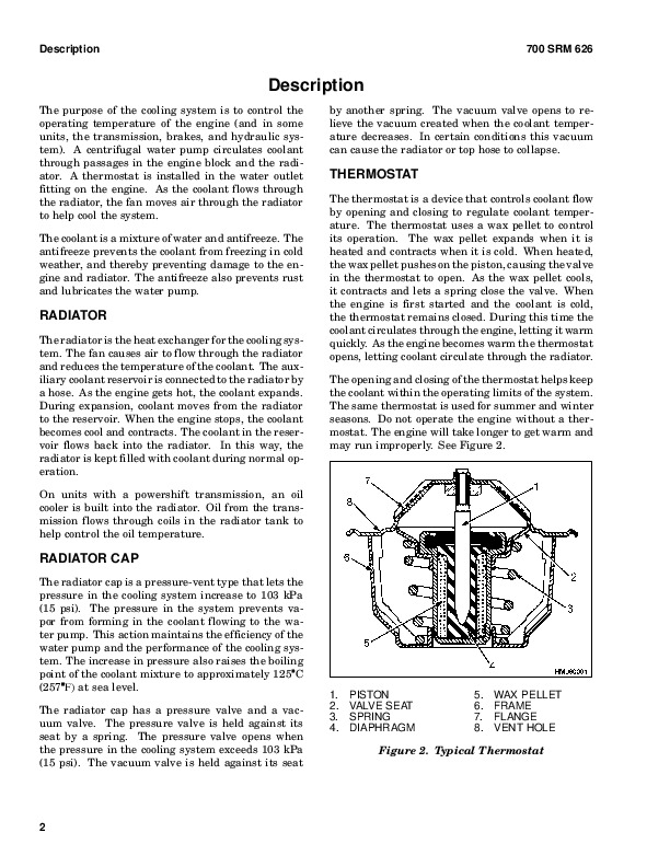
Thermostat…358
Water Pump…359
Fan and Fan Shroud…359
Cooling System Checks…359
Radiator…359
Thermostat…359
Water Pump…360
Exhaust Leaks…360
Fan and Fan Shroud…360
Cooling System Repair…360
Remove…360
Install…361
Core Repair…361
Remove…361
Install…361
Radiator Cleaning…362
Drain…362
Clean…362
Fill…362
Troubleshooting…363
1638475-1300SRM1271-(01-2007)-UK-EN…367
toc…367
Transmission…367
Safety Precautions Maintenance and Repair…368
Description of Operation…371
General…371
Torque Convertor, Pump Drive, and Pressure Regulating Valve…371
Input Shaft and Range Clutches…373
Directional Clutches…374
Output Section…374
Transmission Controls…374
General…374
Operation of the Valve…374
Directional Selection…375
Range Selection…375
Neutral Selection…380
Total Neutral Selection…380
Pressure Switch…380
Electric Solenoid Controls…380
Transmission Specifications…391
Transmission Identification…391
Weight, Dimensions, and Oil Capacity…391
Transmission Repair…392
Remove…392
Disassemble…393
Transmission Case…393
1st Clutch Drum and Turbine Shaft…414
Reverse Clutch Drum…420
2nd Clutch Drum…424
3rd Clutch Drum…427
FWD Clutch Drum…432
Output Shaft…435
Clean and Inspect…437
Housings…437
Oil Seals and Gaskets…437
Bearings…437
Gears and Shafts…438
Assemble…438
Output Shaft…438
FWD Clutch Drum…440
3rd Clutch Drum…445
2nd Clutch Drum…451
REV Clutch Drum…456
1st Clutch Drum and Turbine Shaft…461
Transmission Case…467
Install…488
Stall Test…492
Transmission Calibration and Electrical Troubleshooting…493
Userlink®…493
Connection…493
Clutch Filling Calibration…493
Purpose…493
Clutch Filling Calibration Procedure…494
Alternative Clutch Filling Calibration Procedure…494
Heat-up Mode…495
Heat-up Mode Stall Test…495
Inching Pedal Calibration…496
Purpose…496
Brake Pedal Adjustment…496
Inching Pedal Adjustment…496
Inching Pedal Sensor Adjustment…497
Inching Pedal Calibration Procedure…497
Verification/Adjustment of Inching Pedal Sensor When Pedal is Fu…497
Manual Inching Pedal Sensor Calibration Procedure…498
Troubleshooting…498
Transmission Display Warning Codes…499
Access…499
Clear…499
Exit…499
Limp Home Mode…535
Shutdown Mode…535
Pressure Feedback Sensor…535
Transmission Oil Pressure Check…535
Pressure and Temperature Specifications…535
Electrical Specifications…537
Hydraulic Cooler Lines Specifications…537
Torque Specifications…537
Torque Specifications for Lubricated or Plated Screw Threads…537
tables…367
Table 1. Controller Connector J2 Wire to Pin Number Cross Refere…500
Table 2. Controller Connector J1 Wire to Pin Number Cross Refere…500
Table 3. Common Calibration Condition Messages…502
Table 4. Calibration Codes During Calibration…503
Table 5. Error Codes During Calibration…503
Table 6. Display Warning Codes…504
Table 7. Display Warning Exceed Codes…533
Table 8. Type of Warning Codes…534
Table 9. Grade 5…537
Table 10. Grade 8…538
Table 11. Grades 8.8, 10.9, and 12.9…538
Table 12. Grades 8.8, 10.9, and 12.9…539
Table 13. Elastic Stop Nut Torque…540
Table 14. O-ring Port Plug Torque Chart…540
Table 15. Pipe Plug Torque Chart…540
Table 16. Pipe Plug Torque Chart…540
1638476-1600SRM1272-(12-2006)-UK-EN…547
toc…547
Steering System…547
Safety Precautions Maintenance and Repair…548
General…551
Description…551
Steering Wheel and Column Assembly Repair…553
General…553
Steering Wheel and Horn…553
Remove…553
Install…553
Steering Column…555
Remove…555
Install…555
Steering Control Unit Repair…556
General…556
Description…556
Operation…556
Remove…558
Disassemble…559
Clean…562
Assemble…562
Install…567
Steering System Air Removal…567
Troubleshooting…568
1638479-1900SRM1275-(12-2006)-UK-EN…573
toc…573
Hydraulic System…573
Safety Precautions Maintenance and Repair…574
General…577
Description and Operation…577
Hydraulic Plate…577
Hydraulic Pumps…578
Steering Control System…578
Brake System…578
Tilt Control Valve…579
Hydraulic Pump Repair…579
General…579
Remove…579
Disassemble…579
Clean and Inspect…580
Assemble…582
Install…583
Pump Output Check…583
First Method…583
Second Method…584
Lift and Lower Circuit…585
Description…585
Operation…586
Lift Circuit…587
Lowering…587
Lowering Control Valves…587
Repairs…587
General…587
Remote Control Valve…587
Description and Operation…587
Remove…587
Disassemble…588
Clean and Inspect…589
Assemble…589
Install…589
Adjust…590
Tilt Circuit…590
Description…590
Operation…590
Tilt Spool…591
Relief Valves in Main Control Valve…591
Tilt Control Valves…591
Repairs…592
General…592
Valves, Tilt Control Valves…592
Disassemble…592
Clean and Inspect…592
Assemble…592
Checks and Adjustments…592
Attachment Circuit Valves…592
Description and Operation…592
Other Hydraulic Components…593
Description and Operation…593
Relief Valves in Steering System…593
Hydraulic Filters…593
Hydraulic Filters…593
High Pressure Filter…593
Brake Filter…594
Return Line Filter…594
Hydraulic Tank Breather…595
Hydraulic Hose Repair…596
Checks and Adjustments…596
Main Function Relief Valve Pressure, Check…596
Oil Level, Check…597
Specifications…598
Hydraulic Pumps Output at 2200 rpm (Governed Speed)…598
Cummins 142Hp (190 kW)/164 Hp (220 kW) Engine…598
Relief Valves (Approximate Operating Pressures)…598
Check Port Pressures…598
Main Hydraulic Filters…598
Tank Capacity…598
Torque Specifications…599
Pump…599
Tilt Control Valve…599
Hydraulic Filters…599
Remote Control Valves…599
Troubleshooting…600
Lift and Lower Circuit…600
Tilt Circuit…602
Attachment Circuit Valves…605
Attachment Control Valve…606
Carriage Solenoid Valve…606
Pump…606
Other Hydraulic Components…608
Accumulator Circuit…608
Pilot Circuit…608
Park Brake Circuit…609
tables…573
Table 1. Brake Treadle Settings…579
Table 2. Gauge Ranges…597
Table 3. Pressure Settings…597
1638480-2100SRM1276-(05-2006)-UK-EN…613
toc…613
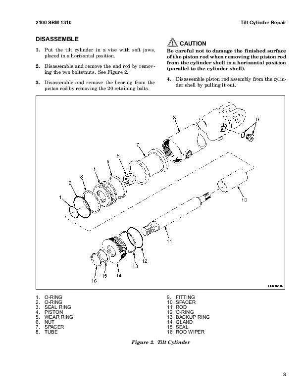
Tilt Cylinders…613
Safety Precautions Maintenance and Repair…614
General…617
Description…617
Tilt Cylinder Repair…617
Remove…617
Disassemble…619
Clean…620
Inspect…620
Assemble…620
Install…621
Tilt Cylinder Leak Check…621
Tilt Cylinder Stroke and Mast Tilt Angle Adjustment…622
Torque Specifications…622
Troubleshooting…623
tables…613
Table 1. Movement Rate (Maximum) for Tilt Cylinders…622
1638481-2000SRM1277-(12-2006)-UK-EN…627
toc…627
Hydraulic Plate…627
Safety Precautions Maintenance and Repair…628
General…631
Description and Operation…632
Hydraulic Oil Supply…632
Main Control Valve, Section 1 of Hydraulic Plate…632
Description…632
Operation…632
Lift Section…633
Tilt Section…633
Auxiliary Section…633
Combination Manifold, Section 2 of Hydraulic Plate…633
Main Control Valve, Section 1 of Hydraulic Plate…635
Remove…635
Disassemble…636
Lift Section…636
Tilt Section…637
Auxiliary Section…637
Spool…637
Relief Valve…637
Clean and Inspect…638
Assemble…638
Relief Valve…638
Spool…638
Auxiliary Section…638
Tilt Section…639
Lift Section…639
Install…639
Combination Manifold, Section 2 of Hydraulic Plate…640
General…640
Valves and Pressure Switches…640
Hydraulic Hose Repair…641
Hydraulic Hose Identification…641
Torque Values…642
Measurements and Adjustments…643
Measurements…643
Adjustments…643
Troubleshooting…644
tables…627
Table 1. Pilot Hoses…641
Table 2. Brake Hoses…641
Table 3. Steer Hoses…641
Table 4. Pressure Settings at 2100 RPM…643
1638482-2200SRM1278-(01-2007)-UK-EN…649
toc…649
Instrument Panel Indicators and Senders…649
Safety Precautions Maintenance and Repair…650
General…653
Description…653
General…653
Instrument Panel Meters, Indicators, and LCD Display…653
Connector…659
Seat Switch Logic…660
Central Warning Light Output…660
Buzzer Output…660
Instrument Panel…661
Remove…662
Sender Replacement…663
Fuel Level Sender…663
Pressure Sender…663
Brake Pressure Sender…664
Low Coolant Sender…664
Vacuum Switch…664
Specifications…665
Troubleshooting…666
tables…649
Table 1. Instrument Panel and Indicators…654
Table 2. Pin Description…659
Table 3. Sender Description…660
1638483-2200SRM1279-(05-2006)-UK-EN…669
toc…669
Electrical System…669
Safety Precautions Maintenance and Repair…670
Description…673
Warning Devices…676
General…676
Description…676
Operator-Controlled Horn…676
Reverse Warning Horns/Lights…676
Warning Lights…677
Strobe Light…677
Brake Lights…677
Hazard Lights…677
Replace…677
General…677
Horns…677
Horn Relay…677
Light Assemblies…679
Flashing Unit…679
Meters, Senders, and Switches…679
General…679
1638484-8000SRM1280-(10-2006)-UK-EN…687
toc…687
Periodic Maintenance…687
Safety Precautions Maintenance and Repair…688
General…693
Serial Number Data…693
How to Move a Disabled Lift Truck…693
How to Tow the Lift Truck…694
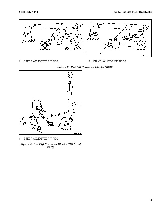
How to Put Lift Truck on Blocks…694
How to Raise the Drive Tires…695
How to Raise the Steer Tires…695
Maintenance Schedule…696
Empty Container Attachment Maintenance…704
Maintenance Procedures Every 8 Hours or Daily…706
How to Make Checks With the Engine Stopped…706
Safety Labels…706
Operator Restraint System…706
Seat Belt and Seat Rails…706
Steering Column Latch…707
Tires and Wheels…707
Inspection of Mast and Lift Chains…707
Drive Belt…708
Crankcase Breather Tube…708
Air Intake Piping and Charge Air Piping…708
Cooling Fan…709
Pre-Cleaner for Air Filter…709
Fuel, Oil, or Coolant Leaks…709
Hydraulic Tank Breather…709
Engine Oil…710
Hydraulic System Oil…710
Brake Filter…711
Battery…711
Fuel Filter/Water Separator…712
Cooling System…712
How to Add Fuel to Lift Truck…713
How to Make Checks With Engine Running…713
Gauges, Lights, Horn, Fuses, and Relays…713
Sealed Fuses…714
Transmission Oil…715
Engine Air Filter…716
Engine Oil Pressure…716
Electrical System…716
Steering System…716
Service Brakes…716
Parking Brake…716
Control Levers and Pedals…716
Lift System Operation…717
Attachments…717
First Inspection After First 100 Hours of Operation…717
Engine Oil Filter…717
Drive Axle and Differential…717
Lift Chains…717
Transmission Oil Filter…718
Air Conditioning…718
Steer Wheel Hubs…718
Maintenance Procedures Every 250 Hours Or Monthly…718
Twist Locks…718
Drive Belt…718
Lift Chains…718
Wheel Nuts…720
Drive Axle and Differential Oil…720
Steering Axle Tie Rods…720
Drive Shaft…720
Mast Pivots, Sliding Surfaces…720
Sideshift Carriage…720
Maintenance Procedures Every 500 Hours or 3 Months…720
Air Conditioning…720
Maintenance Procedures Every 500 Hours or 6 Months…721
Fuel Filter…721
Engine Oil and Filter…721
Maintenance Procedures Every 1000 Hours or 6 Months…721
Brake System Accumulator…721
Steering Axle Kingpins…721
Mast and Carriage Load Rollers…721
Brake Filter…722
Change Transmission Oil and Filter…722
Fan Drive Idler Pulley…722
Fan Hub…723
Maintenance Procedures Every 1500 Hours or 1 Year…724
Engine…724
Water Pump…724
Turbocharger…725
Engine Mounting Bolts…725
Air Leaks, Air Intake and Exhaust…725
Valve and Injector Adjustments…726
General…726
Adjust…727
Maintenance Procedures Every 2000 Hours or 1 Year…729
Drive Axle and Differential Oil…729
Hub Bearings, Steer Wheels…729
Parking Brake Assembly…729
Clean…729
Inspect…730
Vibration Damper…731
Cooling System Fluid…732
Maintenance Procedures Every 3000 Hours or 18 Months…732
Hydraulic System Oil…732
Hydraulic Return Line Oil Filter…733
Maintenance Procedures Every 6000 Hours or 2 Years…733
Turbocharger…733
Safety Procedures When Working Near Mast…734
Lift and Tilt System Leaks Check…735
Lift System…735
Tilt System…735
Pneumatic Tires and Wheels…736
Remove Wheels From Lift Truck…736
Remove Tire From Wheel…736
Remove Tire From Five-Piece Wheel…737
Install Tire on Wheel…738
Install Tire on Five-Piece Wheel…739
Add Air Pressure to Tires…740
Install Wheels on Lift Truck…741
tables…687
Table 1. Condition Check…697
Table 2. Fluid Level Check…698
Table 3. Daily Inspections − Checks With the Engine Running…699
Table 4. First Inspection − Initial 100 – Hour Check or Change…700
Table 5. Periodic Maintenance Schedule − Inspect and Adjust…700
Table 6. Periodic Maintenance Schedule − Lubricate…701
Table 7. Periodic Maintenance Schedule − Change…702
Table 8. Inspect and Adjust…704
Table 9. Lubricate…705
Table 10. Replace…705
Table 11. Valve and Injector Adjustment Specifications…727
1638485-8000SRM1281-(01-2007)-UK-EN…745
toc…745
Diagrams…745
Safety Precautions Maintenance and Repair…746
1638486-8000SRM1282-(06-2006)-UK-EN…785
toc…785
Assembly Guide…785
Safety Precautions Maintenance and Repair…786
List of All Special Tools and Equipment Needed for the Assembly…789
General Considerations Before Starting the Job…790
Preparation of the Components Before Assembly…791
Checking of the Wheels…791
Air Pressure…791
Drive Wheels…792
Steer Wheels…796
Wheel Nut Torque…799
Label Placement…800
Mast Labels…800
Attachment Labels…800
Safety Procedures When Working Near Mast…801
Installation of the Mast…802
Mast…802
Truck Header Hoses-Part 1…803
Mast Pin Installation…804
Tilt Cylinder Pin Installation…806
Truck Header Hoses-Part 2…808
Attachment Connection…809
Exhaust Installation…811
Lights Installation…811
Flood…811
Beacon…811
Hydraulic Oil Check…813
Lubrication Points…814
Check Points…815
Checkpoint 1…815
Checkpoint 2…815
Checkpoint 3…815
Checkpoint 4…815
Checkpoint 5…815
General Truck Install Procedures…815
1643888-1400SRM1296-(12-2006)-UK-EN…819
toc…819
Planetary Gear Axle…819
Safety Precautions Maintenance and Repair…820
General…823
Description…823
Operation…823
Planetary Gear Axle Repair…826
Remove…826
Drive Wheels and Tires…826
Disassemble…827
Drive Axle…827
Planetary Gear Carrier…828
Ring Gear, Ring Gear Hub, and Wheel Hub…829
Hub Oil Seal and Bearings…831
Axle Shaft…831
Spindle…831
Repair…832
Repairing or Replacing Parts…832
Welding…832
Clean…833
Ground or Polished Parts…833
Parts With Rough Finishes…833
Axle Assemblies…833
Drying Cleaned Parts…833
Preventing Corrosion…833
Parts Inspection…834
Assemble…834
Spindle…834
Axle Shaft…834
Hub Oil Seal and Bearings…834
Ring Gear, Ring Gear Hub, and Wheel Hub…835
Wheel Bearing Preload…835
Adjust…835
Planetary Gear Carrier…836
Drive Axle…837
Wheel Ends…838
Fill…838
Install…838
Drive Wheels and Tires…838
Torque Specifications…840
Troubleshooting…841
tables…819
Table 1. Wheel Bearing Adjustment Torque…835
Table 2. Planetary Gear Carrier Capscrew and Stud Torque Specifi…837
Table 3. Standard Torque Values for Axle Fasteners…840
1643889-8000SRM1297-(10-2006)-UK-EN…845
toc…845
Capacities and Specifications…845
Safety Precautions Maintenance and Repair…846
Counterweight Weights…849
Vehicle Weights…849
Container Attachment Weights…849
Capacities…850
Electrical System…850
Engine Specifications…850
Function Speeds…851
Steering…851
Tire Sizes…852
Hydraulic System Specifications…852
Torque Specifications…853
Main Control Valve…853
Engine…853
Electrical System…853
Alternator…853
Counterweight…853
Drive Axle…854
Planetary Gear Axle…854
Steering Axle…854
Wheel Bearing Adjusting Nut (PRC1756-W3H)…854
Differential…854
Transmission…854
Torque Converter…854
Steering…854
Wheel Nuts…854
Attachment…854
897986-1600SRM0658-(12-2006)-UK-EN…857
toc…857
Steering Axle…857
Safety Precautions Maintenance and Repair…858
General…861
Description…861
Steering Axle Repair…861
Remove…861
Install…862
Wheels and Hubs Repair…863
Remove and Disassemble…863
Clean…863
Assemble and Install…863
Spindles and Bearings Repair…864
Remove…864
Clean…864
Assemble and Install…864
Steering Cylinder Repair…865
Remove and Disassemble…865
Clean and Inspect…865
Assemble and Install…866
Troubleshooting…868
897989-4000SRM0661-(05-2006)-UK-EN…871
toc…871
Mast…871
Safety Precautions Maintenance and Repair…872
Safety Procedures When Working Near Mast…875
General…876
Description…876
Operation…877
Control Valve, Carriage/Attachment…878
Tilt Cylinders Repair (A214 Only)…878
Remove…878
Disassemble…878
Clean and Inspect…878
Assemble…879
Install…879
Mast Repair…880
Remove…880
Disassemble…881
Clean and Inspect…882
Assemble…882
Install…885
Lift Cylinders Repair…887
Description…887
Remove…888
Disassemble…888
Clean and Inspect…888
Assemble…888
Install…888
Mast Operation Check…890
Lift and Tilt System Leaks Check…890
Lift System…890
Tilt System…890
Tilt Cylinder Stroke and Backward Tilt Angle Adjustment…891
Lift Chain Adjustments…892
Mast Adjustments…893
Bearing Blocks…893
Wear Plates…893
Carriage Adjustment…895
Troubleshooting…895
tables…871
Table 1. Mast Weights…880
Table 2. Allowable Mast Movement from Internal Leakage (Hydrauli…891
910072-1400SRM0046-(07-2007)-UK-EN…899
toc…899
Differential…899
Safety Precautions Maintenance and Repair…900
General…903
Description…903
Differential Repair…904
Remove…904
Differential Carrier From Axle Housing, Remove…904
Differential and Ring Gear From Differential Carrier, Remove…906
Drive Pinion and Pinion Carrier From Differential Carrier, Remov…908
Disassemble…909
Differential and Ring Gear Assembly, Disassemble…909
Drive Pinion and Pinion Carrier, Disassemble…911
Clean and Inspect…914
Assemble…915
Pinion, Bearings, and Pinion Carrier, Assemble…915
Pinion Bearings, Adjust Preload…915
Press Method…915
Yoke or Flange Method…916
Triple-Lip Seal, Install…917
Pinion Carrier Shim Set, Adjust Thickness (Depth of Pinion)…918
Differential and Ring Gear, Assemble…920
Differential Gears Rotating Torque, Check…922
Differential and Ring Gear Assembly, Install…923
Differential Bearings, Preload Adjust…925
Ring Gear, Runout Check…926
Ring Gear Backlash, Adjust…926
Gear Set, Tooth Contact Pattern Check…928
Thrust Screw, Install and Adjust…931
Install…931
Differential Assembly Into Axle Housing, Install…931
Specifications…933
Troubleshooting…938
tables…899
Table 1. Ring Gear Backlash Adjustment Specifications…928
Table 2. Ring and Pinion Tooth Contact Adjustment…929
Table 3. General Specifications…933
Table 4. Rivet Installation Pressure…933
Table 5. Pinion Adjustment…934
Table 6. Pinion Preload Pressure…934
Table 7. Torque Specifications…935
Table 8. Torque Specifications for Metric Hardware…936
Table 9. Torque Specifications for Metric (Fine) Hardware…937
910119-4000SRM0135-(10-2003)-UK-EN…941
toc…941
Lift Cylinders…941
Safety Precautions Maintenance and Repair…942
Safety Procedures When Working Near Mast…945
General…949
Description…949
Lowering Control Valve…949
Cylinders (General)…952
Cylinders (H520-620B, H700-800A)…952
Retainer, Install…952
Cylinders (H360-460B)…954
Cylinders (Two-Speed)…956
Lift Cylinder Repair…958
Lift Cylinder Removal Without Removing Mast…958
Standard Masts With Main Lift Cylinder Fastened to Crossmember o…958
Standard and Full Free-Lift Masts With Lift Cylinder Fastened to…958
Masts That Have Two Cylinders, Main Lift Cylinder and Free-Lift …958
Disassemble…960
Assemble…960
Lift Cylinder Installation in Mast…962
Standard Masts With Main Lift Cylinder Fastened to Crossmember o…962
Standard and Full Free-Lift Masts With Lift Cylinder Fastened to…962
Chevron-Style Packing…962
Chevron-Style Packing Installation on Piston…963
Chevron-Style Packing Installation in Packing Gland…965
Lift Cylinders for VISTA® Masts…966
Description…966
Lowering Control Valve…966
Remove…968
Disassemble…969
Assemble…970
Install…971
Main Lift Cylinders…971
Free-Lift Cylinder…971
Lift System Leak Check…972
Specifications…973
Troubleshooting…974
tables…941
Table 1. Lift Trucks with Two-Speed Lift Cylinders…957
Table 2. Cylinder Retainer Torque Specifications and Weight Guid…973
910442-8000SRM0231-(12-2004)-UK-EN…977
toc…977
Metric and Inch (SAE) Fasteners…977
Safety Precautions Maintenance and Repair…978
General…981
Threaded Fasteners…981
Nomenclature, Threads…981
Strength Identification…982
Cotter (Split) Pins…982
Fastener Torque Tables…987
Conversion Table…989
tables…977
Table 1. Bolts and Screws…983
Table 2. Studs and Nuts…984
Table 3. Torque Nuts…985
Table 4. Torque Nuts With Nylon Insert…986
Table 5. Torque Values for Metric Fasteners*…987
Table 6. Torque Values for Inch Fasteners*…988
Table 7. Conversion Table for Metric and English Units…989
Table 8. Cotter Pin Dimensional Data…990
Table 9. Cotter Pin Dimensional Data…991
Table 10. Cotter Pin Dimensional Data…992
Table 11. Cotter Pin Dimensional Data…994
Aurora_AC…999
912-100-0148_engl_1.pdf…0
Compressors – Applications, Conditions of Use and Liability…1000
…0
Filling procedure for refrigerants…0
Do not exceed the maximum operating pressure of the compressor. (see type label)…1006
Compressors are machines under pressure and as such require special care in handling…1006
Only qualified personnel are allowed to perform any work on refrigeration compressors…1006
The national safety regulations, accident prevention regulations, technical rules and specific regulations must be taken into account abolutely…1006
Never put the safety switch out of action…1006
Prior to commissioning, check wether all teh components installed by the user have been fastened expertly and connected pressure-tight with the compressor…1006
Prior to starting the compressor open discharge shut-off valve and suction shut-off valve…1006
Do not start the cmpressor in vacuum. Operate the compressor only when the system is charged…1006
Caution! Danger of burning because of high surface temperatures…1006
Never grab rotating parts during operation. Danger of injury!…1006
Avoid all contact with the liquid refrigerant. Any parts of skin that come into contact with it must be treated like chilblains. Wear goggles to protect eyes. If refrigerant nevertheless gets into the eyes, consult a doctor immediately. Wear leather glov…1006
Before repairing refrigerant circuits, all refrigerant must be suctioned off as instructed. Note: Even when the unit is empty, there may be some residual pressure. It is advisable to loosen the screws slowly to allow residual pressure to subside. Refri…1006
No welding may be performed on any part of the unit or in the near vicinity while it is closed. Regardless whether the unit is filled with refrigerant or empty, heating causes excess pressure which can damage the unit or cause an explosion…1006
Full bottles of refrigerant must not be thrown or…1006
It is essential to ensure that the refrigerant system is does not become contaminated with chlorine, substances containing chlorine, oil or grease. Evacuation and filling units must be used for R 134a only…1006
4. Troubleshooting…1007
…1007
…1007
Check refrigerant level and pressure as instructed in the Technical Information sheet for the unit…1007
By wrong refrigerant level there is a danger of compressor malfunction…1007
The outcome of too much refrigerant is a oil attenuation and reflux of the refrigerant can cause damages on the valve plate…1007
With undercharged refrigerant the compressor will become hotwhich caused a failure. The sealing will be damaged…1007
Faulty shaft seals:On older compressors the shaft seal can be damaged when the unit is switched on for first time after a prolonged period of disuse, e.g. if the air-conditioner has not been used during the winter. Seals may become brittle as a result o…1007
NoisesMechanical faults in compressors are generally indicated by unusual noises or by unusually quiet or noisy operation. The normal noise made by the seals during operation does not indicate a fault. The most common noises are caused by problems with…1007
Electrical faultsA 5A fuse is used for the magnetic coupling on the compressor. The magnetic coupling can be checked by applying the required voltage to the connection socket while the vehicle engine is running. The coupling should start up with a click…1007
912-100-0007_e.pdf…0
Technical modifications reserved…1008
912-100-0258_e.pdf…0
Condenser unit, 24V…1019
…1019
…1019
…1019
…1019
part no.:175-FR2-0002…1019
Safety advices…1019
– we reserve the right to make technical modifications -…1019
1Safety advices…1020
Maintenance work on the refrigeration circuit:…1020
…1021
2.2Condenser blowers…1021
5Electrical connection…1022
every six months – authorised workshop:…1023
…1023
…1023
…1023
State of the refrigerant hoses…1023
State of the condenser…1023
A contaminated condenser has a minimised condensing performance. The cleaning is carried out by blow-out or spraying (do not use a high-pressure cleaner)…1023
every month sight checks – Operator…1024
…1024
…1024
…1024
State of the refrigerant hoses…1024
State of the condenser…1024
Check condenser of contamination by dust, insects or parts of plants…1024
A contaminated condenser has a minimised condensing performance. The cleaning is carried out by blow-out or spraying (do not use a high-pressure cleaner)…1024
Installation of replacement parts…1024
8Technical data…1024
9Fault diagnosis…1025
B214 (H400-500HD-EC)…1030
1498450-1800SRM0951-(03-2007)-US-EN…1031
toc…1031
Wet Brake System…1031
Safety Precautions Maintenance and Repair…1032
General…1035
Description and Operation…1035
Service Brakes…1035
Parking Brake…1035
Oil Cooler Circuit…1035
Pressure Switch Replacement…1039
Accumulators Replacement…1039
Brake Treadle Valve Repair…1039
Remove and Disassemble…1039
Clean and Inspect…1040
Assemble and Install…1040
Parking Brake Valve Repair…1040
Remove…1040
Clean and Inspect…1040
Repair…1040
Install…1040
Parking Brake Caliper Repair…1041
Remove…1041
Disassemble…1043
Inspect…1043
Install…1043
Adjust…1043
Brake Pad Repair…1044
Inspect…1044
Remove…1044
Install…1044
Seals Repair…1044
Remove…1044
Install…1045
Service Brake Repair…1045
Remove and Disassemble…1045
Drain Lubricating Oil…1045
Drain Coolant Oil…1052
Disconnect Brake Lines…1052
Wheel End With Outer Bearing on Ring Gear Hub Journal H13.00-14…1052
Wheel End With Outer Bearing on Spindle Journal H8.00-12.00XM (H…1053
Brake Disc Housing Assembly Wheel End…1054
Brake Piston Housing…1055
Brake Piston Housing and Wheel Spindle…1056
Inspect…1056
Clean…1058
Assemble…1059
Wheel Spindle…1059
Brake Piston Housing…1059
Piston Assembly…1061
Brake Disc Housing…1061
Duo-Cone Face Seal Into Brake Disc Housing and Into Hub…1063
Check for Correct Installation of Duo-Cone Seal…1064
Wheel Hub to Brake Disc Housing…1065
Adjust…1066
Fill Brake System With Coolant Oil…1066
System Air Removal…1067
Adjust Brake With New Disc Pack…1067
Coolant Change Intervals…1068
Coolant Draining and Filling…1068
Specifications…1070
Minimum Brake Disc Thickness…1073
Hydraulic Fluid for Brake Actuation…1073
Brake Coolant Specifications…1073
Coolant Change Intervals…1073
Hydraulic Fluid Specifications…1073
Troubleshooting…1073
Brake Does Not Apply…1073
Brake Does Not Release…1074
Brake Performance…1074
Brake Leaks Actuation Fluid…1075
Brake Cooling Fluid Leakage…1076
Brake Noise and Vibration…1076
Brake Overheats…1076
tables…1031
Table 1. Brake Pad Adjustment…1043
Table 2. Minimum Brake Disc Thickness…1057
Table 3. Formed Seal Wear Chart…1057
1509204-5000SRM0990-(10-2007)-US-EN…1081
toc…1081
Empty Container Handling Attachment…1081
Safety Precautions Maintenance and Repair…1082
General…1085
Description…1085
Operation…1096
General…1096
Selector Valves…1096
Sideshift Circuit…1096
Extend and Retract Circuit…1096
Twist Lock Circuit and Control…1096
Model 572 – Double Horizontally Mounted…1096
Model 573 – Horizontally Mounted…1097
Model 578 – Vertically Mounted…1097
Lifting Hooks…1097
Model 575…1097
Indicator Lights and LEDs…1097
Lift Interrupt and Override…1098
Overlowering Interrupt and Override…1098
Second Container Detection Sensor (Model 572 Only)…1099
Carriage and Attachment Repair…1099
Remove…1099
Attachment Without Carriage Repair…1100
Remove…1100
Sideshift Cylinders Repair…1100
Remove…1100
Disassemble…1100
Assemble…1101
Extension Cylinders Repair…1101
Remove…1101
Disassemble…1101
Clean and Inspect…1102
Assemble…1102
Install…1102
Floating End Beams Repair…1103
Remove…1103
Install…1103
Hose Replacement In End Beams…1103
Twist Locks Repair for Model 572 and 573…1103
Remove…1103
Model 573…1103
Model 572…1103
Disassemble…1104
Clean and Inspect…1104
Assemble…1104
Hook Replacement for Model 575…1105
Inspect…1105
Remove…1105
Install…1105
Twist Locks Repair for Model 578…1106
Disassemble…1106
Clean and Inspect…1106
Assemble…1106
Extension Beams Repair…1107
LH and RH Extension Beam, Remove…1107
Slave Beam, Remove…1107
Clean and Inspect…1108
Assemble…1108
Bleed the System…1109
Valve Assembly…1109
Slide Pad Replacement…1110
Adjustments…1110
Twist Lock Angle Adjustment…1110
Model 578 Only…1110
LOCKED/NOT LOCKED Sensors Adjustment…1111
Model 573…1111
Model 578…1111
Seated Sensor Adjustment…1111
Model 572 and 573…1111
Model 578…1112
Overlowering Protection Sensor Adjustment (Models 572, 573, and …1112
Torque Chart…1113
Maintenance…1113
Additional Attachment Maintenance…1116
Interface Boxes With LED Indicators…1117
Models 572, 573, 575, and 578: Interface Box With LED Indicators…1117
Models 573 and 578: Two Additional Interface Boxes With LED Indi…1117
Model 572…1118
Troubleshooting…1118
tables…1081
Table 1. Torque Chart…1113
Table 2. Maintenance Schedule…1114
1529749-1800SRM1036-(07-2007)-US-EN…1149
toc…1149
Brake Accumulator…1149
Safety Precautions Maintenance and Repair…1150
General…1153
Description and Operation…1153
Accumulator Maintenance…1153
Precharge Check…1153
Precharge Filling…1154
Remove…1155
Disassemble…1155
Clean…1157
Inspect…1157
Repair…1157
Assemble…1157
Replace…1157
tables…1149
Table 1. Accumulator Pressures…1154
1564053-0600SRM1101-(11-2007)-US-EN…1161
toc…1161
Cummins Diesel/LPG Engine Fault Code Guide…1161
Safety Precautions Maintenance and Repair…1162
General…1165
Fault Codes…1165
Normal Mode…1165
Fault Log Mode…1165
Access…1165
Exit…1166
Clear…1166
Electronic Throttle Calibration…1166
Electronic Throttle Calibration Procedure…1166
tables…1161
Table 1. Error Code Descriptions…1167
1565789-1800SRM1117-(07-2007)-US-EN…1183
toc…1183
Parking Brake…1183
Safety Precautions Maintenance and Repair…1184
General…1187
Description and Operation…1187
Parking Brake Valve Replacement…1187
Remove…1187
Clean and Inspect…1188
Install…1188
Parking Brake Caliper Repair…1188
Remove…1188
Disassemble…1188
Inspect…1188
Install…1189
Bleed Brakes…1191
Adjust…1191
Brake Pad Repair…1192
Inspect…1192
Remove…1192
Install…1193
Seals Repair…1193
Remove…1193
Install…1193
Specifications…1194
Torque Requirements…1194
Wear Limits…1194
Lining to Disc Clearance…1194
Troubleshooting…1195
tables…1183
Table 1. Brake Pad Adjustment…1192
Table 2. Torque Requirements…1194
Table 3. Wear Limits…1194
Table 4. Lining to Disc Clearance…1194
1612615-5000SRM1221-(11-2006)-US-EN…1199
toc…1199
Extendable Container Attachment (Elme)…1199
Safety Precautions Maintenance and Repair…1200
General…1205
Description…1205
Operation…1209
General…1209
Optional Powered Pile Slope…1209
Sideshift…1210
Extend and Retract Circuit…1211
Container locking Model 582…1213
Sequence Valve…1213
Pilot Check Valve…1214
Container Locking Model 583…1215
Container Locking Model 584…1215
Container Locking Model 585…1216
Container Locking Models 586, 588, and 589…1216
Electrical System…1218
Indicator Lights…1218
Flashing Indicator Lights…1219
Automatic Locking…1219
Lift Interrupt and Override…1219
Overlowering Interrupt and Override…1219
Second Container Detection Sensor (Model 582 Only)…1220
Carriage and Attachment Removal…1220
Carriage…1220
Spreader…1221
Sideshift Cylinder Removal and Installation…1221
Remove…1221
Install…1221
Extension Cylinder Removal and Installation…1222
Remove…1222
Upper, Right-Hand…1222
Lower, Left-Hand…1222
Install…1222
Floating End Beams Repair…1223
Remove…1223
Install…1223
Hose, Replace…1224
Twist Lock Repair for Model 582…1225
Remove…1225
Upper Twist Lock…1225
Lower Twist Lock…1225
Disassemble…1226
Clean and Inspect…1226
Assemble…1227
Install…1227
Hook Repair for Model 584 and 585…1227
Remove…1227
Inspect…1227
Install…1227
Side Clamp Replacement for Model 584…1228
Remove…1228
Install…1229
Twist Lock Repair for Models 586, 588, and 589…1229
Disassemble…1229
Clean and Inspect…1229
Assemble…1230
Extension Beam Repair…1231
Remove…1231
Inspect…1231
Assemble…1232
Cylinder Repair…1233
Extension Cylinder…1233
Disassemble…1233
Clean and Inspect…1233
Assemble…1233
Guide for Extension Cylinder…1234
Remove…1234
Install…1234
Sideshift Cylinder, Powered Pile Slope Cylinder, Retract Cylinde…1234
Disassemble…1234
Assemble…1234
Wear Pad Replacement…1235
General…1235
Floating End Beam Wear Pads…1235
Upper Wear Pads…1235
Lower Wear Pads…1235
Main Frame Wear Pads at Large (Right-Hand) Extension Beam…1235
Main Frame Wear Pads at Small (Left-Hand) Extension Beam…1235
Guide for Extension Cylinder…1236
Large Extension Beam Internal Wear Pads…1237
Spreader Frame…1237
Upper Wear Pads…1237
Lower Wear Pads…1237
Powered Pile Slope Carriage…1237
Upper Wear Pads…1237
Lower Wear Pads…1237
Adjustments…1237
Twist Lock Angle Adjustment…1237
Model 586, 588 and 589…1237
LOCKED/NOT LOCKED Sensors Adjustment…1238
Model 582…1238
Model 586, 588 and 589…1238
Side Clamp Open/Closed Sensor Adjustment (Model 584)…1238
Hook in Sensor Adjustment (Model 584)…1238
Seated Sensor Adjustment…1239
Model 582…1239
Model 586, 588 and 589…1239
Overlowering Protection Sensor Adjustment (All 580 Models)…1239
Schematics…1240
tables…1199
Table 1. Elme Schematic Overview…1240
1638471-0100SRM1267-(10-2006)-US-EN…1327
toc…1327
Frame…1327
Safety Precautions Maintenance and Repair…1328
General…1331
Description…1331
Counterweight Repair…1332
General…1332
Remove…1332
Install…1332
Air Cleaner Repair…1334
Remove…1334
Install…1334
Hoods and Covers…1334
Remove…1334
Install…1334
Floor Plates, Handrails, and Steps…1336
Hydraulic Tank Repair…1337
Remove…1337
Repair…1339
Small Leaks…1339
Large Leaks…1339
Clean…1339
Steam Method…1339
Chemical Solution Method…1340
Other Methods of Preparation for Repair…1340
Install…1340
Fuel Tank Repair…1341
Remove…1341
Repair…1341
Install…1342
Exhaust System Repair…1343
Remove…1343
Install…1343
Engine Repair…1345
Remove…1345
Install…1346
Label Replacement…1348
tables…1327
Table 1. Counterweight Weights…1332
1638472-0100SRM1268-(12-2006)-US-EN…1351
toc…1351
Operator's Cab…1351
Safety Precautions Maintenance and Repair…1352
General…1355
Cab Repair…1356
Rear Cab Assembly…1356
Bottom Cab Assembly…1357
Raising and Lowering Cab…1358
Raise Cab…1358
Lower Cab…1358
Cab Repair…1358
Remove…1358
Install…1359
Oil Filling for Tilt System…1362
Inching and Brake Pedals…1362
Brake Pedal, Adjust…1362
Inching Pedal, Adjust…1363
Inching Pedal Sensor, Adjust…1363
Throttle Pedal Sensor…1363
Check…1363
Adjust…1363
Seat Assembly Removal…1364
Power Assist Armrest…1365
Adjust…1365
Steering Column Repair…1366
Remove…1366
Install…1366
Window Washer Motors and Pumps…1367
Window Wiper and Washer Operating Switches…1367
Window Replacement…1368
Front Window, Replace…1369
Rear Window, Replace…1369
Top Window, Replace…1369
Door Window, Replace…1370
Heater and Air Conditioning Assembly…1371
Heater Parts, Replace…1372
Heat Control Knob/Switches…1372
Heat Control Knob/Cable…1372
Adjust…1372
Air Control Knob/Cable…1373
Adjust…1373
Air Filter, Replace…1373
Air Conditioning Condenser Fan(s)…1374
Remove…1374
Install…1374
Instruments, Switches, and Controls…1374
Switches…1374
Controls…1375
Fuses and Relays…1378
Fuse Panel…1378
Fuses…1379
Relays…1380
Label Replacement…1380
Electrical Schematics…1380
1638474-0700SRM1270-(12-2006)-US-EN…1383
toc…1383
Multiple Aligned Cooling System…1383
Safety Precautions Maintenance and Repair…1384
General…1387
Description…1388
Radiator…1388
Radiator Cap…1388
Thermostat…1388
Water Pump…1389
Fan and Fan Shroud…1389
Cooling System Checks…1389
Radiator…1389
Thermostat…1389
Water Pump…1390
Exhaust Leaks…1390
Fan and Fan Shroud…1390
Cooling System Repair…1390
Remove…1390
Install…1391
Core Repair…1391
Remove…1391
Install…1391
Radiator Cleaning…1392
Drain…1392
Clean…1392
Fill…1392
Troubleshooting…1393
1638475-1300SRM1271-(01-2007)-US-EN…1397
toc…1397
Transmission…1397
Safety Precautions Maintenance and Repair…1398
Description of Operation…1401
General…1401
Torque Convertor, Pump Drive, and Pressure Regulating Valve…1401
Input Shaft and Range Clutches…1403
Directional Clutches…1404
Output Section…1404
Transmission Controls…1404
General…1404
Operation of the Valve…1404
Directional Selection…1405
Range Selection…1405
Neutral Selection…1410
Total Neutral Selection…1410
Pressure Switch…1410
Electric Solenoid Controls…1410
Transmission Specifications…1421
Transmission Identification…1421
Weight, Dimensions, and Oil Capacity…1421
Transmission Repair…1422
Remove…1422
Disassemble…1423
Transmission Case…1423
1st Clutch Drum and Turbine Shaft…1444
Reverse Clutch Drum…1450
2nd Clutch Drum…1454
3rd Clutch Drum…1457
FWD Clutch Drum…1462
Output Shaft…1465
Clean and Inspect…1467
Housings…1467
Oil Seals and Gaskets…1467
Bearings…1467
Gears and Shafts…1468
Assemble…1468
Output Shaft…1468
FWD Clutch Drum…1470
3rd Clutch Drum…1475
2nd Clutch Drum…1481
REV Clutch Drum…1486
1st Clutch Drum and Turbine Shaft…1491
Transmission Case…1497
Install…1518
Stall Test…1522
Transmission Calibration and Electrical Troubleshooting…1523
Userlink®…1523
Connection…1523
Clutch Filling Calibration…1523
Purpose…1523
Clutch Filling Calibration Procedure…1524
Alternative Clutch Filling Calibration Procedure…1524
Heat-up Mode…1525
Heat-up Mode Stall Test…1525
Inching Pedal Calibration…1526
Purpose…1526
Brake Pedal Adjustment…1526
Inching Pedal Adjustment…1526
Inching Pedal Sensor Adjustment…1527
Inching Pedal Calibration Procedure…1527
Verification/Adjustment of Inching Pedal Sensor When Pedal is Fu…1527
Manual Inching Pedal Sensor Calibration Procedure…1528
Troubleshooting…1528
Transmission Display Warning Codes…1529
Access…1529
Clear…1529
Exit…1529
Limp Home Mode…1565
Shutdown Mode…1565
Pressure Feedback Sensor…1565
Transmission Oil Pressure Check…1565
Pressure and Temperature Specifications…1565
Electrical Specifications…1567
Hydraulic Cooler Lines Specifications…1567
Torque Specifications…1567
Torque Specifications for Lubricated or Plated Screw Threads…1567
tables…1397
Table 1. Controller Connector J2 Wire to Pin Number Cross Refere…1530
Table 2. Controller Connector J1 Wire to Pin Number Cross Refere…1530
Table 3. Common Calibration Condition Messages…1532
Table 4. Calibration Codes During Calibration…1533
Table 5. Error Codes During Calibration…1533
Table 6. Display Warning Codes…1534
Table 7. Display Warning Exceed Codes…1563
Table 8. Type of Warning Codes…1564
Table 9. Grade 5…1567
Table 10. Grade 8…1568
Table 11. Grades 8.8, 10.9, and 12.9…1568
Table 12. Grades 8.8, 10.9, and 12.9…1569
Table 13. Elastic Stop Nut Torque…1570
Table 14. O-ring Port Plug Torque Chart…1570
Table 15. Pipe Plug Torque Chart…1570
Table 16. Pipe Plug Torque Chart…1570
1638476-1600SRM1272-(12-2006)-US-EN…1577
toc…1577
Steering System…1577
Safety Precautions Maintenance and Repair…1578
General…1581
Description…1581
Steering Wheel and Column Assembly Repair…1583
General…1583
Steering Wheel and Horn…1583
Remove…1583
Install…1583
Steering Column…1585
Remove…1585
Install…1585
Steering Control Unit Repair…1586
General…1586
Description…1586
Operation…1586
Remove…1588
Disassemble…1589
Clean…1592
Assemble…1592
Install…1597
Steering System Air Removal…1597
Troubleshooting…1598
1638479-1900SRM1275-(12-2006)-US-EN…1603
toc…1603
Hydraulic System…1603
Safety Precautions Maintenance and Repair…1604
General…1607
Description and Operation…1607
Hydraulic Plate…1607
Hydraulic Pumps…1608
Steering Control System…1608
Brake System…1608
Tilt Control Valve…1609
Hydraulic Pump Repair…1609
General…1609
Remove…1609
Disassemble…1609
Clean and Inspect…1610
Assemble…1612
Install…1613
Pump Output Check…1613
First Method…1613
Second Method…1614
Lift and Lower Circuit…1615
Description…1615
Operation…1616
Lift Circuit…1617
Lowering…1617
Lowering Control Valves…1617
Repairs…1617
General…1617
Remote Control Valve…1617
Description and Operation…1617
Remove…1617
Disassemble…1618
Clean and Inspect…1619
Assemble…1619
Install…1619
Adjust…1620
Tilt Circuit…1620
Description…1620
Operation…1620
Tilt Spool…1621
Relief Valves in Main Control Valve…1621
Tilt Control Valves…1621
Repairs…1622
General…1622
Valves, Tilt Control Valves…1622
Disassemble…1622
Clean and Inspect…1622
Assemble…1622
Checks and Adjustments…1622
Attachment Circuit Valves…1622
Description and Operation…1622
Other Hydraulic Components…1623
Description and Operation…1623
Relief Valves in Steering System…1623
Hydraulic Filters…1623
Hydraulic Filters…1623
High Pressure Filter…1623
Brake Filter…1624
Return Line Filter…1624
Hydraulic Tank Breather…1625
Hydraulic Hose Repair…1626
Checks and Adjustments…1626
Main Function Relief Valve Pressure, Check…1626
Oil Level, Check…1627
Specifications…1628
Hydraulic Pumps Output at 2200 rpm (Governed Speed)…1628
Cummins 142Hp (190 kW)/164 Hp (220 kW) Engine…1628
Relief Valves (Approximate Operating Pressures)…1628
Check Port Pressures…1628
Main Hydraulic Filters…1628
Tank Capacity…1628
Torque Specifications…1629
Pump…1629
Tilt Control Valve…1629
Hydraulic Filters…1629
Remote Control Valves…1629
Troubleshooting…1630
Lift and Lower Circuit…1630
Tilt Circuit…1632
Attachment Circuit Valves…1635
Attachment Control Valve…1636
Carriage Solenoid Valve…1636
Pump…1636
Other Hydraulic Components…1638
Accumulator Circuit…1638
Pilot Circuit…1638
Park Brake Circuit…1639
tables…1603
Table 1. Brake Treadle Settings…1609
Table 2. Gauge Ranges…1627
Table 3. Pressure Settings…1627
1638480-2100SRM1276-(05-2006)-US-EN…1643
toc…1643
Tilt Cylinders…1643
Safety Precautions Maintenance and Repair…1644
General…1647
Description…1647
Tilt Cylinder Repair…1647
Remove…1647
Disassemble…1649
Clean…1650
Inspect…1650
Assemble…1650
Install…1651
Tilt Cylinder Leak Check…1651
Tilt Cylinder Stroke and Mast Tilt Angle Adjustment…1652
Torque Specifications…1652
Troubleshooting…1653
tables…1643
Table 1. Movement Rate (Maximum) for Tilt Cylinders…1652
1638481-2000SRM1277-(12-2006)-US-EN…1657
toc…1657
Hydraulic Plate…1657
Safety Precautions Maintenance and Repair…1658
General…1661
Description and Operation…1662
Hydraulic Oil Supply…1662
Main Control Valve, Section 1 of Hydraulic Plate…1662
Description…1662
Operation…1662
Lift Section…1663
Tilt Section…1663
Auxiliary Section…1663
Combination Manifold, Section 2 of Hydraulic Plate…1663
Main Control Valve, Section 1 of Hydraulic Plate…1665
Remove…1665
Disassemble…1666
Lift Section…1666
Tilt Section…1667
Auxiliary Section…1667
Spool…1667
Relief Valve…1667
Clean and Inspect…1668
Assemble…1668
Relief Valve…1668
Spool…1668
Auxiliary Section…1668
Tilt Section…1669
Lift Section…1669
Install…1669
Combination Manifold, Section 2 of Hydraulic Plate…1670
General…1670
Valves and Pressure Switches…1670
Hydraulic Hose Repair…1671
Hydraulic Hose Identification…1671
Torque Values…1672
Measurements and Adjustments…1673
Measurements…1673
Adjustments…1673
Troubleshooting…1674
tables…1657
Table 1. Pilot Hoses…1671
Table 2. Brake Hoses…1671
Table 3. Steer Hoses…1671
Table 4. Pressure Settings at 2100 RPM…1673
1638482-2200SRM1278-(01-2007)-US-EN…1679
toc…1679
Instrument Panel Indicators and Senders…1679
Safety Precautions Maintenance and Repair…1680
General…1683
Description…1683
General…1683
Instrument Panel Meters, Indicators, and LCD Display…1683
Connector…1689
Seat Switch Logic…1690
Central Warning Light Output…1690
Buzzer Output…1690
Instrument Panel…1691
Remove…1692
Sender Replacement…1693
Fuel Level Sender…1693
Pressure Sender…1693
Brake Pressure Sender…1694
Low Coolant Sender…1694
Vacuum Switch…1694
Specifications…1695
Troubleshooting…1696
tables…1679
Table 1. Instrument Panel and Indicators…1684
Table 2. Pin Description…1689
Table 3. Sender Description…1690
1638483-2200SRM1279-(05-2006)-US-EN…1699
toc…1699
Electrical System…1699
Safety Precautions Maintenance and Repair…1700
Description…1703
Warning Devices…1706
General…1706
Description…1706
Operator-Controlled Horn…1706
Reverse Warning Horns/Lights…1706
Warning Lights…1707
Strobe Light…1707
Brake Lights…1707
Hazard Lights…1707
Replace…1707
General…1707
Horns…1707
Horn Relay…1707
Light Assemblies…1709
Flashing Unit…1709
Meters, Senders, and Switches…1709
General…1709
1638484-8000SRM1280-(10-2006)-US-EN…1717
toc…1717
Periodic Maintenance…1717
Safety Precautions Maintenance and Repair…1718
General…1723
Serial Number Data…1723
How to Move a Disabled Lift Truck…1723
How to Tow the Lift Truck…1724
How to Put Lift Truck on Blocks…1724
How to Raise the Drive Tires…1725
How to Raise the Steer Tires…1725
Maintenance Schedule…1726
Empty Container Attachment Maintenance…1734
Maintenance Procedures Every 8 Hours or Daily…1736
How to Make Checks With the Engine Stopped…1736
Safety Labels…1736
Operator Restraint System…1736
Seat Belt and Seat Rails…1736
Steering Column Latch…1737
Tires and Wheels…1737
Inspection of Mast and Lift Chains…1737
Drive Belt…1738
Crankcase Breather Tube…1738
Air Intake Piping and Charge Air Piping…1738
Cooling Fan…1739
Pre-Cleaner for Air Filter…1739
Fuel, Oil, or Coolant Leaks…1739
Hydraulic Tank Breather…1739
Engine Oil…1740
Hydraulic System Oil…1740
Brake Filter…1741
Battery…1741
Fuel Filter/Water Separator…1742
Cooling System…1742
How to Add Fuel to Lift Truck…1743
How to Make Checks With Engine Running…1743
Gauges, Lights, Horn, Fuses, and Relays…1743
Sealed Fuses…1744
Transmission Oil…1745
Engine Air Filter…1746
Engine Oil Pressure…1746
Electrical System…1746
Steering System…1746
Service Brakes…1746
Parking Brake…1746
Control Levers and Pedals…1746
Lift System Operation…1747
Attachments…1747
First Inspection After First 100 Hours of Operation…1747
Engine Oil Filter…1747
Drive Axle and Differential…1747
Lift Chains…1747
Transmission Oil Filter…1748
Air Conditioning…1748
Steer Wheel Hubs…1748
Maintenance Procedures Every 250 Hours Or Monthly…1748
Twist Locks…1748
Drive Belt…1748
Lift Chains…1748
Wheel Nuts…1750
Drive Axle and Differential Oil…1750
Steering Axle Tie Rods…1750
Drive Shaft…1750
Mast Pivots, Sliding Surfaces…1750
Sideshift Carriage…1750
Maintenance Procedures Every 500 Hours or 3 Months…1750
Air Conditioning…1750
Maintenance Procedures Every 500 Hours or 6 Months…1751
Fuel Filter…1751
Engine Oil and Filter…1751
Maintenance Procedures Every 1000 Hours or 6 Months…1751
Brake System Accumulator…1751
Steering Axle Kingpins…1751
Mast and Carriage Load Rollers…1751
Brake Filter…1752
Change Transmission Oil and Filter…1752
Fan Drive Idler Pulley…1752
Fan Hub…1753
Maintenance Procedures Every 1500 Hours or 1 Year…1754
Engine…1754
Water Pump…1754
Turbocharger…1755
Engine Mounting Bolts…1755
Air Leaks, Air Intake and Exhaust…1755
Valve and Injector Adjustments…1756
General…1756
Adjust…1757
Maintenance Procedures Every 2000 Hours or 1 Year…1759
Drive Axle and Differential Oil…1759
Hub Bearings, Steer Wheels…1759
Parking Brake Assembly…1759
Clean…1759
Inspect…1760
Vibration Damper…1761
Cooling System Fluid…1762
Maintenance Procedures Every 3000 Hours or 18 Months…1762
Hydraulic System Oil…1762
Hydraulic Return Line Oil Filter…1763
Maintenance Procedures Every 6000 Hours or 2 Years…1763
Turbocharger…1763
Safety Procedures When Working Near Mast…1764
Lift and Tilt System Leaks Check…1765
Lift System…1765
Tilt System…1765
Pneumatic Tires and Wheels…1766
Remove Wheels From Lift Truck…1766
Remove Tire From Wheel…1766
Remove Tire From Five-Piece Wheel…1767
Install Tire on Wheel…1768
Install Tire on Five-Piece Wheel…1769
Add Air Pressure to Tires…1770
Install Wheels on Lift Truck…1771
tables…1717
Table 1. Condition Check…1727
Table 2. Fluid Level Check…1728
Table 3. Daily Inspections − Checks With the Engine Running…1729
Table 4. First Inspection − Initial 100 – Hour Check or Change…1730
Table 5. Periodic Maintenance Schedule − Inspect and Adjust…1730
Table 6. Periodic Maintenance Schedule − Lubricate…1731
Table 7. Periodic Maintenance Schedule − Change…1732
Table 8. Inspect and Adjust…1734
Table 9. Lubricate…1735
Table 10. Replace…1735
Table 11. Valve and Injector Adjustment Specifications…1757
1638485-8000SRM1281-(01-2007)-US-EN…1775
toc…1775
Diagrams…1775
Safety Precautions Maintenance and Repair…1776
1638486-8000SRM1282-(06-2006)-US-EN…1815
toc…1815
Assembly Guide…1815
Safety Precautions Maintenance and Repair…1816
List of All Special Tools and Equipment Needed for the Assembly…1819
General Considerations Before Starting the Job…1820
Preparation of the Components Before Assembly…1821
Checking of the Wheels…1821
Air Pressure…1821
Drive Wheels…1822
Steer Wheels…1826
Wheel Nut Torque…1829
Label Placement…1830
Mast Labels…1830
Attachment Labels…1830
Safety Procedures When Working Near Mast…1831
Installation of the Mast…1832
Mast…1832
Truck Header Hoses-Part 1…1833
Mast Pin Installation…1834
Tilt Cylinder Pin Installation…1836
Truck Header Hoses-Part 2…1838
Attachment Connection…1839
Exhaust Installation…1841
Lights Installation…1841
Flood…1841
Beacon…1841
Hydraulic Oil Check…1843
Lubrication Points…1844
Check Points…1845
Checkpoint 1…1845
Checkpoint 2…1845
Checkpoint 3…1845
Checkpoint 4…1845
Checkpoint 5…1845
General Truck Install Procedures…1845
1643888-1400SRM1296-(12-2006)-US-EN…1849
toc…1849
Planetary Gear Axle…1849
Safety Precautions Maintenance and Repair…1850
General…1853
Description…1853
Operation…1853
Planetary Gear Axle Repair…1856
Remove…1856
Drive Wheels and Tires…1856
Disassemble…1857
Drive Axle…1857
Planetary Gear Carrier…1858
Ring Gear, Ring Gear Hub, and Wheel Hub…1859
Hub Oil Seal and Bearings…1861
Axle Shaft…1861
Spindle…1861
Repair…1862
Repairing or Replacing Parts…1862
Welding…1862
Clean…1863
Ground or Polished Parts…1863
Parts With Rough Finishes…1863
Axle Assemblies…1863
Drying Cleaned Parts…1863
Preventing Corrosion…1863
Parts Inspection…1864
Assemble…1864
Spindle…1864
Axle Shaft…1864
Hub Oil Seal and Bearings…1864
Ring Gear, Ring Gear Hub, and Wheel Hub…1865
Wheel Bearing Preload…1865
Adjust…1865
Planetary Gear Carrier…1866
Drive Axle…1867
Wheel Ends…1868
Fill…1868
Install…1868
Drive Wheels and Tires…1868
Torque Specifications…1870
Troubleshooting…1871
tables…1849
Table 1. Wheel Bearing Adjustment Torque…1865
Table 2. Planetary Gear Carrier Capscrew and Stud Torque Specifi…1867
Table 3. Standard Torque Values for Axle Fasteners…1870
1643889-8000SRM1297-(10-2006)-US-EN…1875
toc…1875
Capacities and Specifications…1875
Safety Precautions Maintenance and Repair…1876
Counterweight Weights…1879
Vehicle Weights…1879
Container Attachment Weights…1879
Capacities…1880
Electrical System…1880
Engine Specifications…1880
Function Speeds…1881
Steering…1881
Tire Sizes…1882
Hydraulic System Specifications…1882
Torque Specifications…1883
Main Control Valve…1883
Engine…1883
Electrical System…1883
Alternator…1883
Counterweight…1883
Drive Axle…1884
Planetary Gear Axle…1884
Steering Axle…1884
Wheel Bearing Adjusting Nut (PRC1756-W3H)…1884
Differential…1884
Transmission…1884
Torque Converter…1884
Steering…1884
Wheel Nuts…1884
Attachment…1884
897986-1600SRM0658-(12-2006)-US-EN…1887
toc…1887
Steering Axle…1887
Safety Precautions Maintenance and Repair…1888
General…1891
Description…1891
Steering Axle Repair…1891
Remove…1891
Install…1892
Wheels and Hubs Repair…1893
Remove and Disassemble…1893
Clean…1893
Assemble and Install…1893
Spindles and Bearings Repair…1894
Remove…1894
Clean…1894
Assemble and Install…1894
Steering Cylinder Repair…1895
Remove and Disassemble…1895
Clean and Inspect…1895
Assemble and Install…1896
Troubleshooting…1898
897989-4000SRM0661-(05-2006)-US-EN…1901
toc…1901
Mast…1901
Safety Precautions Maintenance and Repair…1902
Safety Procedures When Working Near Mast…1905
General…1906
Description…1906
Operation…1907
Control Valve, Carriage/Attachment…1908
Tilt Cylinders Repair (A214 Only)…1908
Remove…1908
Disassemble…1908
Clean and Inspect…1908
Assemble…1909
Install…1909
Mast Repair…1910
Remove…1910
Disassemble…1911
Clean and Inspect…1912
Assemble…1912
Install…1915
Lift Cylinders Repair…1917
Description…1917
Remove…1918
Disassemble…1918
Clean and Inspect…1918
Assemble…1918
Install…1918
Mast Operation Check…1920
Lift and Tilt System Leaks Check…1920
Lift System…1920
Tilt System…1920
Tilt Cylinder Stroke and Backward Tilt Angle Adjustment…1921
Lift Chain Adjustments…1922
Mast Adjustments…1923
Bearing Blocks…1923
Wear Plates…1923
Carriage Adjustment…1925
Troubleshooting…1925
tables…1901
Table 1. Mast Weights…1910
Table 2. Allowable Mast Movement from Internal Leakage (Hydrauli…1921
910072-1400SRM0046-(07-2007)-US-EN…1929
toc…1929
Differential…1929
Safety Precautions Maintenance and Repair…1930
General…1933
Description…1933
Differential Repair…1934
Remove…1934
Differential Carrier From Axle Housing, Remove…1934
Differential and Ring Gear From Differential Carrier, Remove…1936
Drive Pinion and Pinion Carrier From Differential Carrier, Remov…1938
Disassemble…1939
Differential and Ring Gear Assembly, Disassemble…1939
Drive Pinion and Pinion Carrier, Disassemble…1941
Clean and Inspect…1944
Assemble…1945
Pinion, Bearings, and Pinion Carrier, Assemble…1945
Pinion Bearings, Adjust Preload…1945
Press Method…1945
Yoke or Flange Method…1946
Triple-Lip Seal, Install…1947
Pinion Carrier Shim Set, Adjust Thickness (Depth of Pinion)…1948
Differential and Ring Gear, Assemble…1950
Differential Gears Rotating Torque, Check…1952
Differential and Ring Gear Assembly, Install…1953
Differential Bearings, Preload Adjust…1955
Ring Gear, Runout Check…1956
Ring Gear Backlash, Adjust…1956
Gear Set, Tooth Contact Pattern Check…1958
Thrust Screw, Install and Adjust…1961
Install…1961
Differential Assembly Into Axle Housing, Install…1961
Specifications…1963
Troubleshooting…1968
tables…1929
Table 1. Ring Gear Backlash Adjustment Specifications…1958
Table 2. Ring and Pinion Tooth Contact Adjustment…1959
Table 3. General Specifications…1963
Table 4. Rivet Installation Pressure…1963
Table 5. Pinion Adjustment…1964
Table 6. Pinion Preload Pressure…1964
Table 7. Torque Specifications…1965
Table 8. Torque Specifications for Metric Hardware…1966
Table 9. Torque Specifications for Metric (Fine) Hardware…1967
910119-4000SRM0135-(10-2003)-US-EN…1971
toc…1971
Lift Cylinders…1971
Safety Precautions Maintenance and Repair…1972
Safety Procedures When Working Near Mast…1975
General…1979
Description…1979
Lowering Control Valve…1979
Cylinders (General)…1982
Cylinders (H520-620B, H700-800A)…1982
Retainer, Install…1982
Cylinders (H360-460B)…1984
Cylinders (Two-Speed)…1986
Lift Cylinder Repair…1988
Lift Cylinder Removal Without Removing Mast…1988
Standard Masts With Main Lift Cylinder Fastened to Crossmember o…1988
Standard and Full Free-Lift Masts With Lift Cylinder Fastened to…1988
Masts That Have Two Cylinders, Main Lift Cylinder and Free-Lift …1988
Disassemble…1990
Assemble…1990
Lift Cylinder Installation in Mast…1992
Standard Masts With Main Lift Cylinder Fastened to Crossmember o…1992
Standard and Full Free-Lift Masts With Lift Cylinder Fastened to…1992
Chevron-Style Packing…1992
Chevron-Style Packing Installation on Piston…1993
Chevron-Style Packing Installation in Packing Gland…1995
Lift Cylinders for VISTA® Masts…1996
Description…1996
Lowering Control Valve…1996
Remove…1998
Disassemble…1999
Assemble…2000
Install…2001
Main Lift Cylinders…2001
Free-Lift Cylinder…2001
Lift System Leak Check…2002
Specifications…2003
Troubleshooting…2004
tables…1971
Table 1. Lift Trucks with Two-Speed Lift Cylinders…1987
Table 2. Cylinder Retainer Torque Specifications and Weight Guid…2003
910442-8000SRM0231-(12-2004)-US-EN…2007
toc…2007
Metric and Inch (SAE) Fasteners…2007
Safety Precautions Maintenance and Repair…2008
General…2011
Threaded Fasteners…2011
Nomenclature, Threads…2011
Strength Identification…2012
Cotter (Split) Pins…2012
Fastener Torque Tables…2017
Conversion Table…2019
tables…2007
Table 1. Bolts and Screws…2013
Table 2. Studs and Nuts…2014
Table 3. Torque Nuts…2015
Table 4. Torque Nuts With Nylon Insert…2016
Table 5. Torque Values for Metric Fasteners*…2017
Table 6. Torque Values for Inch Fasteners*…2018
Table 7. Conversion Table for Metric and English Units…2019
Table 8. Cotter Pin Dimensional Data…2020
Table 9. Cotter Pin Dimensional Data…2021
Table 10. Cotter Pin Dimensional Data…2022
Table 11. Cotter Pin Dimensional Data…2024
Aurora_AC…2029
912-100-0148_engl_1.pdf…0
Compressors – Applications, Conditions of Use and Liability…2030
…0
Filling procedure for refrigerants…0
Do not exceed the maximum operating pressure of the compressor. (see type label)…2036
Compressors are machines under pressure and as such require special care in handling…2036
Only qualified personnel are allowed to perform any work on refrigeration compressors…2036
The national safety regulations, accident prevention regulations, technical rules and specific regulations must be taken into account abolutely…2036
Never put the safety switch out of action…2036
Prior to commissioning, check wether all teh components installed by the user have been fastened expertly and connected pressure-tight with the compressor…2036
Prior to starting the compressor open discharge shut-off valve and suction shut-off valve…2036
Do not start the cmpressor in vacuum. Operate the compressor only when the system is charged…2036
Caution! Danger of burning because of high surface temperatures…2036
Never grab rotating parts during operation. Danger of injury!…2036
Avoid all contact with the liquid refrigerant. Any parts of skin that come into contact with it must be treated like chilblains. Wear goggles to protect eyes. If refrigerant nevertheless gets into the eyes, consult a doctor immediately. Wear leather glov…2036
Before repairing refrigerant circuits, all refrigerant must be suctioned off as instructed. Note: Even when the unit is empty, there may be some residual pressure. It is advisable to loosen the screws slowly to allow residual pressure to subside. Refri…2036
No welding may be performed on any part of the unit or in the near vicinity while it is closed. Regardless whether the unit is filled with refrigerant or empty, heating causes excess pressure which can damage the unit or cause an explosion…2036
Full bottles of refrigerant must not be thrown or…2036
It is essential to ensure that the refrigerant system is does not become contaminated with chlorine, substances containing chlorine, oil or grease. Evacuation and filling units must be used for R 134a only…2036
4. Troubleshooting…2037
…2037
…2037
Check refrigerant level and pressure as instructed in the Technical Information sheet for the unit…2037
By wrong refrigerant level there is a danger of compressor malfunction…2037
The outcome of too much refrigerant is a oil attenuation and reflux of the refrigerant can cause damages on the valve plate…2037
With undercharged refrigerant the compressor will become hotwhich caused a failure. The sealing will be damaged…2037
Faulty shaft seals:On older compressors the shaft seal can be damaged when the unit is switched on for first time after a prolonged period of disuse, e.g. if the air-conditioner has not been used during the winter. Seals may become brittle as a result o…2037
NoisesMechanical faults in compressors are generally indicated by unusual noises or by unusually quiet or noisy operation. The normal noise made by the seals during operation does not indicate a fault. The most common noises are caused by problems with…2037
Electrical faultsA 5A fuse is used for the magnetic coupling on the compressor. The magnetic coupling can be checked by applying the required voltage to the connection socket while the vehicle engine is running. The coupling should start up with a click…2037
912-100-0007_e.pdf…0
Technical modifications reserved…2038
912-100-0258_e.pdf…0
Condenser unit, 24V…2049
…2049
…2049
…2049
…2049
part no.:175-FR2-0002…2049
Safety advices…2049
– we reserve the right to make technical modifications -…2049
1Safety advices…2050
Maintenance work on the refrigeration circuit:…2050
…2051
2.2Condenser blowers…2051
5Electrical connection…2052
every six months – authorised workshop:…2053
…2053
…2053
…2053
State of the refrigerant hoses…2053
State of the condenser…2053
A contaminated condenser has a minimised condensing performance. The cleaning is carried out by blow-out or spraying (do not use a high-pressure cleaner)…2053
every month sight checks – Operator…2054
…2054
…2054
…2054
State of the refrigerant hoses…2054
State of the condenser…2054
Check condenser of contamination by dust, insects or parts of plants…2054
A contaminated condenser has a minimised condensing performance. The cleaning is carried out by blow-out or spraying (do not use a high-pressure cleaner)…2054
Installation of replacement parts…2054
8Technical data…2054
9Fault diagnosis…2055
Hyster B214 (H16.00-22.00XM-12EC Europe & H400-500HD-EC) Repair Service Manuals