Posted on

Hyster H135-155XL2 (G006) Repair Service Manual


INSTANT DOWNLOAD


Complete service repair manual for Hyster Lift Trucks H135XL2, H155XL2 (G006), with all the technical information to maintain, diagnose, repair, and service like professional mechanics.

Hyster Service Manual H135-155XL2 (G006) workshop service & repair manual includes:
* Numbered table of contents easy to use so that you can find the information you need fast.
* Detailed sub-steps expand on repair procedure information
* Numbered instructions guide you through every repair procedure step by step.
* Troubleshooting and electrical service procedures are combined with detailed wiring diagrams for ease of use.
* Notes, cautions and warnings throughout each chapter pinpoint critical information.
* Bold figure number help you quickly match illustrations with instructions.
* Detailed illustrations, drawings and photos guide you through every procedure.
* Enlarged inset helps you identify and examine parts in detail.

Total Pages: 1,149 pages
File Format: PDF (Internal Links, Bookmarked, Table of Contents, Searchable, Printable, high quality)
Language: English

1559725 – Hyster Service Manual H135-155XL2 (G006).pdf

 
Section Part No. SRM Number Rev Date
FRAME 897104 0100 SRM 0322 11/03
GM V6-4.3L ENGINE WITH FUEL INJECTION 897800 0600 SRM 0590 11/03
PERKINS DIESEL ENGINE 1104 (RE) 155202 0600 SRM 1070 12/03
COOLING SYSTEM 897934 0700 SRM 0626 11/01
ELECTRONIC CONTROLLED LPG/GASOLINE FUEL SYSTEM GM 3.0L & 4.3L
EPA COMPLIANT ENGINES
1559540 0900 SRM 1088 03/04
TWO-SPEED PS TRANS-DESCR / OPER 897106 1300 SRM 0324 10/03
TWO-SPEED PS TRANSMISSION-REPAIR 897107 1300 SRM 0325 10/03
DIFFERENTIAL 910072 1400 SRM 0046 11/03
DRIVE AXLE 910073 1400 SRM 0049 09/03
STEERING CONTROL UNIT 910076 1600 SRM 0054 10/03
STEERING AXLE 897108 1600 SRM 0326 10/03
BRAKE SYSTEM 897109 1800 SRM 0327 09/03
HYDRAULIC GEAR PUMPS 910091 1900 SRM 0097 10/03
HYDRAULIC SYSTEM 897110 1900 SRM 0328 09/03
MAIN CONTROL VALVE 899783 2000 SRM 0090 10/03
TILT CYLINDERS 910102 2100 SRM 0103 10/03
ALTERNATOR 899784 2200 SRM 0002 10/03
STARTER 910107 2200 SRM 0106 02/01
INSTRUMENT PANEL INDICATORS / SENDERS 910110 2200 SRM 0143 12/03
ELECTRONIC CONTROL MODULE (ECM) DIAGNOSTIC TROUBLESHOOTING
GM 3.0L AND 4.3L EPA COMPLIANT ENGINES
1559545 2200 SRM 1090 01/04
HIGH VOLTAGE SWITCH (HVS) IGNITION GM 4.3L EPA COMPLIANT ENGINES 1559550 2200 SRM 1097 12/03
LIFT CYLINDERS 910119 4000 SRM 0135 10/03
MASTS 897111 4000 SRM 0329 10/03
METRIC AND INCH (SAE) FASTENERS 910442 8000 SRM 0231 03/03
CAPACITIES and SPECIFICATIONS 897113 8000 SRM 0331 09/03
PERIODIC MAINTENANCE 897123 8000 SRM 0341 12/03
DIAGRAMS-GM ELECTRONIC ENGINE CONTROL 897501 8000 SRM 0519 12/03
 
PART NO. 1559725
Rev. 03/04

    Perkins Diesel Engines…2
    Safety Precautions Maintenance and Repair…3
    General…10
      General Safety Rules…10
    Description…11
      Engine Serial Number Codes…11
      Engine Data…13
    Engine Removal and Installation…14
    Cylinder Head Assembly Repair…14
      Engine Breather…14
        Remove…14
        Install…14
      Valve Cover…15
        Remove…15
        Install…15
      Rocker Arm Assembly…17
        Remove…17
        Disassemble…17
        Inspect…17
        Assemble…17
        Install…18
      Valve Clearance Adjustments…18
      Valve Springs…19
      Cylinder Head Assembly…20
        Remove…20
        Inspect…21
        Install…22
      Valves and Valve Springs…23
        Remove…23
        Inspect…24
        Install…24
      Valve Guides…25
        Inspect…25
        Remove…25
        Install…25
      Valve Seats…27
        Inspect…27
        Repair…27
        New Valve Seats, Install…28
    Piston and Connecting Rod Assemblies Repair…28
      General…28
      Rod Bearings…29
        Remove…29
        Install…29
      Piston and Connecting Rod Assembly…30
        Service Note…30
        Remove…30
        Disassemble…31
        Inspect…31
        How to Select Correct Replacements…32
        Assemble…33
        Install…34
      Piston Cooling Jets…35
        Remove…35
        Install…36
    Crankshaft Assembly Repair…36
      General…36
      Crankshaft Pulley…36
        Remove…36
        Inspect…36
        Install…37
      Rear Oil Seal…37
        Remove…37
        Install…37
      Crankshaft Flange Wear Sleeve…39
        Remove…39
        Install…39
      Main Bearings…40
        Remove…40
        Inspect…40
        Install…41
      Thrust Washers…42
        Crankshaft Axle Movement, Check…42
        Remove…42
        Install…43
      Crankshaft…43
        Remove…43
        Inspect…44
        Install…44
      Crankshaft Timing Ring…46
        Remove…46
        Install…46
      Flywheel…46
        Remove…46
        Ring Gear, Replace…47
        Install…47
      Flywheel Housing…47
        Remove…47
        Install…48
    Timing Case and Timing Gears Repair…48
      General…48
      Timing Case Cover…48
        Remove…48
        Install…49
      Front Oil Seal…50
        Remove, With Timing Case Installed…50
        Install, With Timing Case Installed…50
        Remove, With Timing Case Removed…51
        Install, With Timing Case Removed…51
      Crankshaft Pulley Wear Sleeve, Install…52
      Fuel Pump Gear…52
        Remove…52
        Install…54
      Idler Gear and Hub…55
        Remove…55
        Disassemble…56
          Standard Idler Gear and Hub Assembly…56
          Heavy Duty Idler Gear and Hub Assembly…56
        Assemble…56
          Standard Idler Gear and Hub Assembly…56
          Heavy Duty Idler Gear and Hub Assembly…57
        Install…57
      Camshaft Gear…58
        Remove…58
        Install…58
      Crankshaft Gear…59
        Remove…59
        Install…59
      Timing Case…59
        Remove…59
        Install…60
      Power Take-Off (PTO) Adaptor…61
        Remove…61
        Disassemble…62
        Assemble…62
        Install…62
      Camshaft and Tappets…62
        Remove…62
        Install…63
    Cylinder Block Assembly Repair…63
      General…63
      Cylinder Block…64
        Disassemble…64
        Inspect…64
        Assemble…64
      Cylinder Bore…65
        Inspect…65
        Cylinder Liner Condition Check…65
    Engine Timing…65
      General…65
      How to Set Number One Piston to TDC on Compression Stroke…65
      Fuel Injection Pump Timing, Check…67
      Fuel Injection Pump Timing, Adjust…68
    Lubrication System Repair…69
      General…69
      Oil Filter, Replace…69
      Oil Filter Head…70
        Remove…70
        Install…70
      Oil Sump…71
        Remove…71
        Install…71
      Oil Pump…72
        Remove…72
        Inspect…72
        Install…73
      Oil Strainer and Suction Pipe…74
        Remove…74
        Install…74
      Relief Valve…74
        Remove…74
        Install…74
      Dipstick Tube…75
        Remove and Install…75
    Fuel System Repair…75
      General…75
      Cold Start Advance Unit (KSB)…76
      Typical Fuel System…77
      Fuel Filter…78
        Remove…78
        Install…78
      Fuel Injectors…79
        Remove…79
        Install…80
      Fuel System Air Removal…81
      Bosch EVPE Fuel Injection Pump…81
        General…81
        Remove…82
        Install…83
    Cooling System Repair…83
      General…83
      Thermostat…85
        Remove…85
        Install…85
        Test…86
      Coolant Pump…86
        Remove…86
        Disassemble…87
        Assemble…88
        Install…89
      Fan…89
        Remove and Install…89
      Fan Drive…90
        Remove…90
        Install…90
      Oil Cooler…90
        Remove…90
        Disassemble and Assemble…90
        Install…91
      Coolant By-Pass Hose…91
        Removal…91
        Install…91
    Electrical Equipment Repair…91
      Drive Belt…91
        Check…91
        Adjust…92
        Remove…92
        Install…92
      Alternator…92
        Remove…92
        Install…92
        Fault Diagnosis…93
          Normal Operation:…93
          If the warning lamp is not illuminated when the ignition switch …93
          If the Warning Light Continues to be Illuminated When the Altern…94
      Starter Motor…94
        Remove…94
        Install…95
        Test…95
      Starting Aid…95
        Remove…95
        Install…95
        Check…96
          Power Supply Continuity…96
          Operation…96
      Pressure Sensor…97
        Remove…97
        Install…98
      Temperature Sensor…98
        Remove…98
        Install…98
    Engine Specifications…99
      Cylinder Head Assembly…99
      Piston and Connecting Rods…102
      Crankshaft Assembly…103
        Crankshaft Overhaul…103
      Timing Case and Drive Assembly…105
      Engine Block Assembly…106
      Lubrication System…107
      Fuel System…107
      Cooling System…108
      Flywheel and Housing…109
      Electrical Equipment…109
    Torque Specifications…109
    Special Torque Specifications…110
      Cylinder Head Assembly…110
      Piston and Connecting Rod Assemblies…110
      Crankshaft Assembly…110
      Timing Case and Drive Assembly…110
      Cylinder block…110
      Fuel System…110
      Lubrication System…110
      Cooling System…111
      Flywheel and Housing…111
      Electrical Equipment…111
    Special Tools…112
    Troubleshooting…115
  tables…2
    Table 1. Cylinder Head…99
    Table 2. Valve Guides…99
    Table 3. Inlet Valves…100
    Table 4. Exhaust Valves…100
    Table 5. Valve Springs…101
    Table 6. Tappets…101
    Table 7. Rocker Arm Shaft…101
    Table 8. Rocker Arms and Bushings…102
    Table 9. Pistons…102
    Table 10. Piston Rings…102
    Table 11. Piston Pins…102
    Table 12. Connecting Rods…102
    Table 13. Small End Bushings…103
    Table 14. Connecting Rod Bearings…103
    Table 15. Piston Cooling Jets…103
    Table 16. Crankshaft Overhaul Specifications…104
    Table 17. Maximum Variation (Run-out)…105
    Table 18. Camshaft…105
    Table 19. Camshaft Thrust Washer…105
    Table 20. Camshaft Gear…105
    Table 21. Gear for Fuel Pump…105
    Table 22. Crankshaft Gear…105
    Table 23. Idler Gear and Hub…106
    Table 24. Timing Gear Backlash Values…106
    Table 25. Cylinder Block…106
    Table 26. Oil Pump…107
    Table 27. Idler Gear for Oil Pump…107
    Table 28. Relief Valve…107
    Table 29. Oil Filter…107
    Table 30. Bosch Fuel Injection Pump…107
    Table 31. Fuel Injector Settings…108
    Table 32. Fuel Pump…108
    Table 33. Fuel Filter…108
    Table 34. Coolant Pump…108
    Table 35. Thermostat…108
    Table 36. Fan Drive Housing…109
    Table 37. Limits for Flywheel Run Out and Alignment (Total Indic…109
    Table 38. Alternator…109
    Table 39. Starter Motor…109
    Table 40. Starting Aids…109
    Table 41. List of Possible Causes…116
hyster-1559540-03-04-srm1088…120
  toc…120
    Electronic Controlled LPG/Gasoline Fuel System…120
    Safety Precautions Maintenance and Repair…121
    General…126
      Fuel System Warnings and Cautions…126
    Glossary…127
    Description and Operation of LPG Fuel System…131
      Propane Fuel System…131
      LPG Fuel Tank…131
      Service Line…131
      Fuel Filter…131
      Low Pressure Lock-Off (LPL)…131
      Low Pressure Regulator (LPR)…133
      Air Fuel Mixer…134
      Throttle Control Device…135
        Drive By Cable…135
      Three-Way Catalytic (TWC) Muffler…136
      Electronic Control Module (ECM)…136
      Heated Exhaust Gas Oxygen (HEGO) Sensor…138
    Description and Operation of Gasoline Fuel System…138
      Gasoline Fuel System Throttle Body Injection (TBI), 3.0L Engine …138
      Gasoline Multi-Point Fuel Injection (MPFI) System, 4.3L Only…138
      Gasoline Fuel Storage Tank…140
      Gasoline Fuel Pump…140
      Fuel Filter…140
      Fuel Pressure Regulator, 3.0L Only…140
      Fuel Rail and Pressure Regulator, 4.3L Only…142
      Fuel Injector…143
      Throttle Control Device…143
        Drive By Cable…143
      Three-Way Catalytic Muffler…143
      Electronic Control Module (ECM)…144
      Heated Exhaust Gas Oxygen (HEGO) Sensor…146
    LPG Fuel System Repair…146
      Propane Fuel System Pressure Relief…146
      Propane Fuel System Leak Test…146
      Propane Fuel Filter Replacement…147
        Remove…147
        Install…147
      Low Pressure Lock-Off (LPL) Replacement…147
        Remove…147
        Install…147
      Pressure Trim Valve (PTV) Replacement…148
        Remove…148
        Install…149
      Low Pressure Regulator…149
        Remove…149
        Install…149
      Fuel Trim Valve (FTV) Solenoid Replacement…150
        Remove…150
        Install…151
      Temperature Manifold Absolute Pressure (TMAP)…151
        Remove…151
        Install…151
      Throttle Body Replacement…151
        Remove…151
        Install…152
      Mixer Replacement…152
        Remove…152
        Install…152
      Coolant Hose Replacement…152
        Remove…152
        Install…152
      Vapor Hose Replacement…153
        Remove…153
        Install…153
      Balance Line Hose Replacement…153
        Remove…153
        Install…153
      PTV Hose Replacement…153
        Remove…153
        Install…153
      FTV Hose Replacement…153
        Remove…153
        Install…154
      Throttle Position Sensor (TPS) Replacement…154
        Remove…154
        Install…154
      Foot Pedal Position (FPP) Sensor Replacement…154
        Remove…154
        Install…154
      Electronic Control Module (ECM) Replacement…154
        Remove…154
        Install…155
      Heated Exhaust Gas Oxygen (HEGO) Sensor Replacement…155
        Remove…155
        Install…155
      Three-Way Catalytic Muffler (TWC) Replacement…155
        Remove…155
        Install…155
      Restricted Exhaust System Diagnosis…155
        Exhaust System Description…155
          Tools Required…156
          Diagnostic Tool…156
        Check at Heated Exhaust Gas Oxygen Sensor (HEGO)…156
    Gasoline Fuel System Repair…157
      Gasoline MPFI and TBI Fuel System Pressure Relief…157
      Gasoline Fuel System Leak Test…157
      Throttle Body Injector (TBI) Assembly Replacement, 3.0L Only…157
        Remove…157
        Install…158
      Throttle Body Assembly Replacement, 3.0L Only…158
        Remove…158
        Install…158
      Throttle Body Assembly Replacement, 4.3L Only…159
        Remove…159
        Install…159
      Fuel Rail Replacement, Gasoline 4.3L Only…160
        Remove…160
        Install…160
      Injector Replacement, Gasoline 4.3L Only…160
        Remove…160
        Install…160
      Injector Replacement, Gasoline 3.0L Only…162
        Remove…162
        Install…162
      Temperature Manifold Absolute Pressure (TMAP) Replacement…162
        Remove…162
        Install…162
      Throttle Position Sensor (TPS) Replacement…162
        Remove…162
        Install…162
      Foot Pedal Position (FPP) Sensor Replacement…163
        Remove…163
        Install…163
      Electronic Control Module (ECM) Replacement…163
        Remove…163
        Install…163
      Heated Exhaust Gas Oxygen (HEGO) Sensor Replacement…163
        Remove…163
        Install…163
      Three-Way Catalytic Muffler (TWC) Replacement…164
        Remove…164
        Install…164
      Restricted Exhaust System Diagnosis…164
        Exhaust System Description…164
          Tools Required…164
          Diagnostic Tool…164
        Check at Heated Exhaust Gas Oxygen Sensor (HEGO)…164
    LPG System Diagnosis…165
      Fuel System Description…165
      Diagnostic Aids…166
        Tools Required…166
        Duty Cycle Monitoring Tool…166
        Diagnostic Tool…166
        Pressure Gauges…166
        Test Description…166
    Gasoline System Diagnosis…173
      Fuel System Description, 3.0L Only…173
      Fuel System Description, 4.3L Only…174
      Diagnostic Aids…174
        Tools Required…175
        Diagnostic Tool…175
        Test Description…175
    LPG Symptom Diagnosis…182
    Gasoline Symptom Diagnosis…195
    Wire Harness Repair…205
      On Vehicle Service Wiring Harness Repair…205
      Connectors and Terminals…206
        Twisted/Shielded Cable Repair…206
        Twisted Leads Repair…207
        Micro-Pack…208
        Metri-Pack…208
          Remove…208
        Weather-Pack…210
          Weather-Pack Terminal Repair…211
  tables…120
    Table 1. LPG Fuel System Diagnosis…166
    Table 2. Fuel Control Diagnosis…170
    Table 3. Gasoline Fuel System Diagnosis, 3.0L Only…176
    Table 4. Gasoline Fuel System Diagnosis, 4.3L Only…179
    Table 5. Preliminary Checks…182
    Table 6. Intermittent …183
    Table 7. No Start…184
    Table 8. Hard Start…185
    Table 9. Cuts Out or Misses…187
    Table 10. Hesitation, Sag, or Stumble…188
    Table 11. Backfire…189
    Table 12. Lack of Power, Sluggishness, or Sponginess…190
    Table 13. Poor Fuel Economy…191
    Table 14. Rough, Unstable, Incorrect Idle, or Stalling…192
    Table 15. Surges or Chuggles…194
    Table 16. Preliminary Checks…195
    Table 17. Intermittent…196
    Table 18. No Start…197
    Table 19. Hard Start…198
    Table 20. Cuts Out or Misses…199
    Table 21. Hesitation, Sag, or Stumble…200
    Table 22. Backfire…201
    Table 23. Lack of Power, Sluggishness, or Sponginess…202
    Table 24. Poor Fuel Economy…203
    Table 25. Rough, Unstable, Incorrect Idle, or Stalling…204
    Table 26. Surges or Chuggles…205
hyster-1559545-01-04-srm1090…216
  toc…216
    Electronic Control Module (ECM) Diagnostic Troubleshooting…216
    Safety Precautions Maintenance and Repair…217
    General…224
    Description of ECM Based Diagnostics…224
      Definition of Terms…224
      Diagnostics Overview of the Spectrum Fuel System…224
      Malfunction Indicator Lamp (MIL)…225
      Spectrum Diagnostic Trouble Codes (DTC)…225
      Using a Laptop Computer to Diagnose the Spectrum System…225
        Installing the Spectrum Diagnostic Software…225
        Connecting a Laptop Computer to the Spectrum System…226
      Diagnostic Trouble Codes…226
        Checking Diagnostic Trouble Codes…226
        Clearing Diagnostic Trouble Codes…227
      DATA Stream…227
        Reading Sensor and Actuator Values…227
        Graphing and Data Logging…228
      Ignition System Test…229
        Disabling Ignition Outputs…229
      Injector Test…230
        Disabling Injectors…230
      Throttle Test…231
        Using a Diagnostic Jumper to Diagnose the ECI System…231
    On-Board Diagnostics System Check/Malfunction indicator lamp…232
      Circuit Description…232
    Preliminary and Intermittent Checks…235
    DTC 111 – IAT High Voltage Bosch® TMAP…237
      Circuit Description…237
      Conditions for Setting the DTC…237
    DTC 111 – IAT High Voltage Motorola® TMAP…240
      Circuit Description…240
      Conditions for Setting the DTC…240
    DTC 112 – IAT Low Voltage Bosch® TMap…243
      Circuit Description…243
      Conditions for Setting the DTC…243
    DTC 112 – IAT Low Voltage Motorola® TMAP…245
      Circuit Description…245
      Conditions for Setting the DTC…245
    DTC 113 – IAT Higher Than Expected 1 Bosch® TMAP…248
      Circuit Description…248
      Conditions for Setting the DTC…248
      Diagnostic Aids…248
    DTC 113 – IAT Higher Than Expected 1 Motorola® TMAP…249
      Circuit Description…249
      Conditions for Setting the DTC…249
      Diagnostic Aids…249
    DTC 114 – IAT Higher Than Expected 2 Bosch® TMAP…250
      Circuit Description…250
      Conditions for Setting the DTC…250
      Diagnostic Aids…250
    DTC 114 – IAT Higher Than Expected 2 Motorola® TMAP…251
      Circuit Description…251
      Conditions for Setting the DTC…251
      Diagnostic Aids…251
    DTC 115 – Oil Pressure Low…252
      Circuit Description…252
      Conditions for Setting the DTC…252
    DTC 121 – ECT Voltage High…255
      Circuit Description…255
      Conditions for Setting the DTC…256
    DTC 122 – ECT Low Voltage…259
      Circuit Description…259
      Conditions for Setting the DTC…259
    DTC 123 – ECT Higher Than Expected 1…261
      Circuit Description…261
      Conditions for Setting the DTC…261
    DTC 124 – ECT Higher Than Expected 2…263
      Circuit Description…263
      Conditions for Setting the DTC…263
    DTC 131 – MAP High Pressure Bosch® TMAP…264
      Circuit Description…264
      Conditions for Setting the DTC…264
      Diagnostic Aids…265
    DTC 131 – MAP High Pressure Motorola® TMAP…267
      Circuit Description…267
      Conditions for Setting the DTC…267
      Diagnostic Aids…268
    DTC 132 – MAP Low Voltage Bosch® TMAP…271
      Circuit Description…271
      Conditions for Setting the DTC…271
    DTC 132 – MAP Low Voltage Motorola® TMAP…275
      Circuit Description…275
      Conditions for Setting the DTC…275
    DTC 134 – BP High Pressure Bosch® TMAP…279
      Circuit Description…279
      Conditions for Setting the DTC…279
    DTC 134 – BP High Pressure Motorola® TMAP…281
      Circuit Description…281
      Conditions for Setting the DTC…281
    DTC 135 – BP Low Pressure Bosch® TMAP…283
      Circuit Description…283
      Conditions for Setting the DTC…283
    DTC 135 – BP Low Pressure Motorola® TMAP…287
      Circuit Description…287
      Conditions for Setting the DTC…287
    DTC 142 – Crank Sync Noise…291
      Circuit Description…291
      Conditions for setting the DTC…291
    DTC 143 – Never Crank Synced At Start…294
      Circuit Description…294
      Conditions for Setting the DTC…294
    DTC 144 – Camshaft Sensor Loss…297
      Circuit Description…297
      Conditions for Setting the DTC…297
    DTC 145 – Camshaft Sensor Noise…300
      Circuit Description…300
      Conditions for Setting the DTC…300
    DTC 211 – Closed Loop Multiplier High (LPG)…303
      Circuit Description…303
      Conditions for Setting the DTC…303
      Diagnostic Aids…304
    DTC 212 – HO 2 S Open/Inactive…305
      Circuit Description…305
      Conditions for Setting the DTC…305
    DTC 213 – HO 2 S Open/Inactive (Post-Cat)…309
      Circuit Description…309
      Conditions for Setting the DTC…309
    DTC 221 – Closed Loop Multiplier High (Gasoline)…311
      Circuit Description…311
      Conditions for Setting the DTC…311
      Diagnostic Aids…311
    DTC 222 – Closed Loop Multiplier Low (Gasoline)…314
      Circuit Description…314
      Conditions for Setting the DTC…314
      Diagnostic Aids…315
    DTC 224 – Closed Loop Multiplier Low (LPG)…316
      Circuit Description…316
      Conditions for Setting the DTC…316
      Diagnostic Aids…317
    DTC 241 – Adaptive Lean Fault (High Limit-Gasoline)…318
      Circuit Description…318
      Conditions for Setting the DTC…318
      Diagnostic Aids…319
    DTC 242 – Adaptive Rich Fault (Low Limit-Gasoline)…321
      Circuit Description…321
      Conditions for Setting the DTC…321
      Diagnostic Aids…321
    DTC 243 – Adaptive Learn High (LPG)…323
      Circuit Description…323
      Conditions for Setting the DTC…323
      Diagnostic Aids…324
    DTC 244 – Adaptive Learn Low (LPG)…327
      Circuit Description…327
      Conditions for Setting the DTC…327
      Diagnostic Aids…328
    DTC 261 – System Voltage Low…330
      Circuit Description…330
      Conditions for Setting the DTC…330
    DTC 262 – System Voltage High…333
      Circuit Description…333
      Conditions for Setting the DTC…333
    DTC 411 – Injector Driver 1 Open (3.0L only)…335
      Circuit Description…335
      Conditions for Setting the DTC…335
    DTC 412 – Injector Driver 1 Shorted (3.0L only)…338
      Circuit Description…338
      Conditions for Setting the DTC…338
    DTC 511 – COP Failure…341
      Circuit Description…341
      Conditions for Setting the DTC…341
    DTC 512 – Invalid Interrupt…343
      Circuit Description…343
      Conditions for Setting the DTC…343
    DTC 513 – A/D Loss…345
      Circuit Description…345
      Conditions for Setting the DTC…345
    DTC 514 – RTI 1 Loss…347
      Circuit Description…347
      Conditions for Setting the DTC…347
    DTC 515 – Flash Checksum Invalid…349
      Circuit Description…349
      Conditions for Setting the DTC…349
    DTC 516 – Ram Failure…351
      Circuit Description…351
      Conditions for Setting the DTC…351
    DTC 531 – External 5V Ref Lower Than Expected…353
      Circuit Description…353
      Conditions for Setting the DTC…353
    DTC 532 – External 5V Ref Higher Than Expected…355
      Circuit Description…355
      Conditions for Setting the DTC…355
    DTC 555 – RTI 2 Loss…357
      Circuit Description…357
      Conditions for Setting the DTC…357
    DTC 556 – RTI 3 Loss…359
      Circuit Description…359
      Conditions for Setting the DTC…359
    DTC 611 – FPP High Voltage…361
      Circuit Description…361
      Conditions for Setting the DTC…361
    DTC 612 – FPP Low Voltage…365
      Circuit Description…365
      Conditions for Setting the DTC…365
    DTC 631 – TPS1 Signal Voltage High…369
      Circuit Description…369
      Conditions for Setting the DTC…369
    DTC 632 – TPS1 Signal Voltage Low…372
      Circuit Description…372
      Conditions for Setting the DTC…372
    DTC 637 – Throttle Unable To Open…375
      Circuit Description…375
      Conditions for Setting the DTC…375
    DTC 638 – Throttle Unable To Close…377
      Circuit Description…377
      Conditions for Setting the DTC…377
    DTC 651 – Maximum Govern Speed Override…381
      Circuit Description…381
      Conditions for Setting the DTC…381
    DTC 652 – Fuel Rev Limit…383
      Circuit Description…383
      Conditions for Setting the DTC…383
    DTC 653 – Spark Rev Limit…386
      Circuit Description…386
      Conditions for Setting the DTC…386
    Wire Harness Repair…388
      On Vehicle Service Wiring Harness Repair…388
      Connectors and Terminals…389
        Twisted/Shielded Cable Repair…389
        Twisted Leads Repair…390
        Micro-Pack…391
        Metri-Pack…391
          Remove…391
        Weather-Pack…393
          Weather-Pack Terminal Repair…393
  tables…216
    Table 1. OBD System Check…233
    Table 2. Preliminary Checks…235
    Table 3. Intermittent Checks…236
    Table 4. DTC 111 – IAT Voltage High (Bosch® TMAP)…238
    Table 5. DTC 111 – IAT Voltage High (Motorola® TMAP)…241
    Table 6. DTC 112 – IAT Low Voltage (Bosch® TMAP)…244
    Table 7. DTC 112 – IAT Low Voltage (Motorola® TMAP)…246
    Table 8. DTC 115 – Oil Pressure Low…253
    Table 9. Temperature Resistance…255
    Table 10. DTC 121 – ECT VOLTAGE HIGH…256
    Table 11. DTC 122 – ECT Low Voltage…260
    Table 12. DTC 123 – ECT Higher Than Expected 1…262
    Table 13. DTC 124 – ECT Higher Than Expected 2…264
    Table 14. DTC 131 – MAP HIGH PRESSURE (Bosch® TMAP)…265
    Table 15. DTC 131 – MAP HIGH PRESSURE (Motorola® TMAP)…268
    Table 16. DTC 132 – MAP Low Voltage (Bosch® TMAP)…272
    Table 17. DTC 132 – MAP Low Voltage (Motorola® TMAP)…276
    Table 18. DTC 134 – BP High Pressure (Bosch® TMAP)…280
    Table 19. DTC 134 – BP High Pressure (Motorola® TMAP)…282
    Table 20. DTC 135 – BP Low Pressure (Bosch® TMAP)…284
    Table 21. DTC 135 – BP Low Pressure (Motorola® TMAP)…288
    Table 22. DTC 142 – Crank Sync Noise…292
    Table 23. DTC 143 – Never Crank Synced At Start…294
    Table 24. DTC 144 – Camshaft Sensor Loss…297
    Table 25. DTC 145 – Camshaft Sensor Noise…301
    Table 26. DTC 211 – Closed Loop Multiplier High (LPG)…304
    Table 27. DTC 212 – HO 2 S Open/Inactive…306
    Table 28. DTC 213 – HO 2 S Open/Inactive (Post-Cat)…310
    Table 29. DTC 221 – Closed Loop Multiplier High (Gasoline)…312
    Table 30. DTC 222 – Closed Loop Multiplier Low (Gasoline)…315
    Table 31. DTC 224 – Closed Loop Multiplier Low (LPG)…317
    Table 32. DTC 241 – Adaptive Lean Fault (High Limit-Gasoline)…319
    Table 33. DTC 242 – Adaptive Rich Fault (Low Limit-Gasoline)…322
    Table 34. DTC 243 – Adaptive Learn High (LPG)…325
    Table 35. DTC 244 – Adaptive Learn Low (LPG)…328
    Table 36. DTC 261 – System Voltage Low…331
    Table 37. DTC 262 – System Voltage High…334
    Table 38. DTC 411 – Injector Driver 1 Open (3.0L Only)…336
    Table 39. DTC 412 – Injector Driver 1 Shorted (3.0L only)…339
    Table 40. DTC 511 – COP Failure…342
    Table 41. DTC 512 – Invalid Interrupt…344
    Table 42. DTC 513 – A/D Loss…346
    Table 43. DTC 514 – RTI 1 Loss…348
    Table 44. DTC 515 – Flash Checksum Invalid…350
    Table 45. DTC 516 – Ram Failure…352
    Table 46. DTC 531 – External 5V Ref Lower Than Expected…354
    Table 47. DTC 532 – External 5 V Ref Higher Than Expected…356
    Table 48. DTC 555 – RTI 2 Loss…358
    Table 49. DTC 556 – RTI 3 Loss…360
    Table 50. DTC 611 – FPP High Voltage…362
    Table 51. DTC 612 – FPP Low Voltage…366
    Table 52. DTC 631 – TPS1 Signal Voltage High…370
    Table 53. DTC 632 – TPS1 Signal Voltage Low…373
    Table 54. DTC 637 – Throttle Unable To Open…376
    Table 55. DTC 638 – Throttle Unable To Close…378
    Table 56. DTC 651 – Maximum Govern Speed Override…382
    Table 57. DTC 652 – Fuel Rev Limit…384
    Table 58. DTC 653 – Spark Rev Limit…387
hyster-1559550-12-03-srm1097…398
  toc…398
    High Voltage Switch (HVS) Ignition…398
    Safety Precautions Maintenance and Repair…399
    Description…402
      Distributor Ignition (DI) System…402
      Crankshaft Position (CKP) Sensor…402
      Camshaft Position (CMP) Sensor…402
      Ignition Coil and Ignition Control Module (ICM)…402
      Secondary Ignition Components…402
    Spark Plugs and Wires…402
      Spark Plug Wire Inspection…402
      Spark Plug Wire Replacement…402
        Remove…402
        Install…403
      Spark Plug Inspection…403
        Usage…403
        Inspection…403
        Visual Inspection…405
      Spark Plug Replacement…405
        Remove…405
        Install…405
    Distributor Repair…406
      Inspect…406
      Overhaul…406
        Disassemble…406
        Assemble…409
      Replace…409
        Remove…409
        Install Procedure 1…411
        Install Procedure 2…412
    Ignition Coil Replacement…414
      Remove…414
      Install…414
    Ignition Control Module Replacement…415
      Remove…415
      Install…415
    Camshaft Position (CMP) Sensor Replacement…415
      Remove…415
      Install…417
    Crankshaft Position (CKP) Sensor Replacement…417
      Remove…417
      Install…417
    Wire Harness Repair…419
      On Vehicle Service Wiring Harness Repair…419
      Connectors and Terminals…419
        Twisted/Shielded Cable Repair…420
        Twisted Leads Repair…421
        Micro-Pack…421
        Metri-Pack…421
          Remove…422
        Weather-Pack…423
          Weather-Pack Terminal Repair…424
    Specifications and Special Tools…425
    System Diagnosis…427
  tables…398
    Table 1. Ignition System Specifications…425
    Table 2. Fastener Tightening Specifications…425
    Table 3. Special Tools…426
    Table 4. Distributor Ignition (DI)…427
hyster-897104-11-03-srm0322…434
  toc…434
    Frame…434
    Safety Precautions Maintenance and Repair…435
    General…438
    Description…438
    Counterweight Repair…439
      Remove…439
      Install…439
    Hood Repair…440
      Remove…440
      Install…440
    Overhead Guard Repair…440
      Remove…440
      Install…440
    Operator Restraint System Repair…441
    Hydraulic Tank Repair…442
      Remove…442
      Inspect…442
      Small Leaks Repair…442
      Large Leaks Repair…442
      Clean…442
        Steam Method…443
        Chemical Solution Method…443
      Other Methods of Preparation for Repair…443
      Install…443
    Fuel Tank Repair…444
      Remove…444
      Repair…444
      Install…444
    Radiator Repair…444
      Remove…444
      Install…444
    Engine Repair…445
      Remove…445
      Install…445
    Safety Labels…447
    Cab Repair…449
      Cab, Replace…449
      Window, Replace…449
      Windshield Wipers and Heater…449
  tables…434
    Table 1. Material Specifications for Cab Windows…451
hyster-897106-10-03-srm0324…454
  toc…454
    Two-Speed Powershift Transmission…454
    Safety Precautions Maintenance and Repair…455
    General…458
    Mechanical Description…458
      Torque Converter…458
      Transmission Pump…459
      Shaft Assemblies…459
      Input Shaft…460
      Forward Clutch Shaft…460
      Clutch Assemblies…460
      Countershaft…467
      Output Shaft…467
    Hydraulic Operation…468
      Torque Converter…468
      Seal Rings…469
    Control Valve…469
      System Pressure Regulator…472
      Clutch Pressure Regulator…472
      Torque Converter Regulator…473
      Inching Spool…473
      Direction Spool, Direction Control Lever…473
      Direction Spool, MONOTROL Pedal…474
      Range Spool…474
      Drain Spool…475
      Accumulator…475
      Modulator Spool…475
      Operation…475
    Lubrication Circuit…476
    MONOTROL Pedal…476
    Oil Flow Diagrams…478
      Neutral…478
      Forward-Low…479
      Forward-Low-Inching…480
      Reverse-Low…481
hyster-897107-10-03-srm0325…484
  toc…484
    Two-Speed Powershift Transmission…484
    Safety Precautions Maintenance and Repair…485
    General…488
    Transmission Repair…488
      Transmission and Torque Converter, Remove…488
      Transmission, Disassemble…490
      Reverse-Low Clutch, Disassemble…493
      Reverse-High Clutch, Disassemble…496
      Forward-Low Clutch, Disassemble…499
      Forward-High Clutch, Disassemble…502
      Clean and Inspect…504
    Forward Low and High Clutches Assembly…505
      Forward Clutches, Assemble…507
      Reverse-Low Clutch, Assemble…513
      Reverse Clutches, Assemble…515
      Transmission, Assemble…522
      Torque Converter, Install…529
    Control Valve Repair…530
      Remove…530
      Disassemble…531
      Assemble…532
      Install…534
    MONOTROL Pedal…534
      Remove and Disassemble…534
      Assemble and Install…534
    Stall Test…537
    Linkage Adjustments…538
      Linkage for Inching Pedal H6.00-7.00XL (H135-155XL, H135-155XL 2…538
      Linkage for Inching Pedal S6.00-7.00XL (S135-155XL, S135-155XL 2…541
      Linkage for Range Lever – Early Model H6.00-7.00XL (H135-155XL) …544
      Linkage for Direction Control Lever – Early Model H6.00-7.00XL (…544
      Linkage for Range Lever – Later Model H6.00-7.00XL (H135-155XL, …546
      Linkage for Direction Control Lever – Later Model H6.00-7.00XL (…548
      Linkage for Range Lever S6.00-7.00XL (S135-155XL, S135-155XL 2 )…550
      Linkage for Direction Control Lever S6.00-7.00XL (S135-155XL, S1…550
    Oil Pressure Check…552
      System Pressure Check Port…552
      Torque Converter Check Port…552
      Clutch Pressure Check Port…552
      Inching Pressure…553
      Solenoid Check Ports (MONOTROL Control Only)…553
      Lubrication Pressure Check Ports…553
    Specifications…554
    Troubleshooting…554
      Correct System Pressure: 1300 ±124 kPa ( 189 ±18 psi)…557
      Correct Clutch Pressure: 924 ±69 kPa ( 134 ±10 psi)…558
      Correct Solenoid Pressure (MONOTROL Only): 965 ±138 kPa ( 140 ±2…559
      Torque Converter Pressure: 834 ±69 kPa ( 121 ±10 psi)…559
      Lubrication Pressure: 83 ±21 kPa ( 12 ±3 psi)…559
  tables…484
    Table 1. Stall Speed Specifications…537
hyster-897108-10-03-srm0326…562
  toc…562
    Steering Axle…562
    Safety Precautions Maintenance and Repair…563
    General…566
    Description…566
    Steering Axle Assembly Repair…570
      Steering Axle H3.50-5.00XL (H70-110XL) (G005), S3.50-5.50XL (S70…570
        Remove…570
        Install…571
      Steering Axle H6.00-7.00XL (H135-155XL, H135-155XL 2 ) (F006, G0…571
        Remove…571
        Install…572
    Wheels and Hubs Repair (All Units)…572
      Remove and Disassemble…572
      Clean…572
      Inspect…572
      Assemble and Install…573
    Spindles and Bearings Repair (All Units)…574
      Remove…574
      Clean…574
      Assemble and Install…574
    Tie Rods Repair (All Units)…575
      Remove…575
      Clean…575
      Install…575
    Steering Cylinder Repair…578
      Remove and Disassemble…578
      Clean and Inspect…578
      Assemble and Install…578
    Troubleshooting…579
hyster-897109-09-03-srm0327…584
  toc…584
    Brake System…584
    Safety Precautions Maintenance and Repair…585
    General…588
    Description…588
    Operation…589
      Brake Booster and Master Cylinder…589
        Brake Booster…589
        Master Cylinder…590
      Service Brake Assembly…591
      Parking Brake…592
    Brake Shoe Assemblies Repair…593
      Remove and Disassemble…593
      Clean and Inspect…594
        Cleaning Procedures…594
        Inspect…594
      Assemble and Install…595
    Master Cylinder Repair…596
      Remove…596
      Disassemble…596
      Assemble…598
      Install…598
    Brake Booster Repair…598
      Remove…598
      Disassemble…598
      Clean and Inspect…600
      Assemble…600
      Install…600
    Brake System Air Removal…600
    Brake Pedal Adjustment…601
    Brake Shoes Adjustment…602
    Parking Brake Adjustment…602
    Parking Brake Switch Adjustment…602
    Brake Booster Relief Valve Check…602
    Troubleshooting…603
hyster-897110-09-03-srm0328…608
  toc…608
    Hydraulic System…608
    Safety Precautions Maintenance and Repair…609
    General…612
    Description and Operation…612
      Hydraulic Pumps…614
      Main Control Valve…614
      Control Valve Lever…615
      Steering Control Unit…615
      Brake Valve…615
      Oil Clutch, H6.00-7.00XL (H135-155XL) (F006)…616
    Troubleshooting…616
      Lift, Lower, and Tilt Circuit…617
      Steering, Brake, and Oil Clutch System…618
hyster-897111-10-03-srm0329…622
  toc…622
    Masts…622
    Safety Precautions Maintenance and Repair…623
    General…626
    Description and Operation…626
      General…626
      Safety Procedures When Working Near Mast…627
      Two-Stage Mast…627
      Three-Stage Mast…629
    Carriage Repair…631
      Remove…631
      Sideshift Carriage, Disassemble…631
      Sideshift Carriage, Assemble…632
      Install…632
    Two-Stage Mast Repair…634
      Remove…634
      Disassemble…635
      Clean and Inspect…636
      Assemble…637
      Install…637
    Three-Stage Mast Repair…639
      Remove…639
      Disassemble…639
      Clean and Inspect…639
      Assemble…639
      Install…641
    Mast Operation Check…641
    Lift and Tilt System Leaks Check…642
      Lift System…642
      Tilt System…642
    Tilt Cylinder Stroke and Backward Tilt Angle Adjustment…643
    Lift Chain Adjustments…643
    Mast Adjustments…646
    Carriage Adjustment…646
    Troubleshooting…648
  tables…622
    Table 1. Mast Parts Weight…635
    Table 2. Hook-Type Carriage Chain Adjustment…644
    Table 3. Pin-Type Carriage Chain Adjustment…644
hyster-897113-09-03-srm0331…652
  toc…652
    Capacities and Specifications…652
    Safety Precautions Maintenance and Repair…653
    Lift Truck Weights…656
    Capacities…656
    Tire Sizes…657
    Tire Pressure…657
    Electrical System…657
    Wheel Nut Torque…657
    Engine Specifications…658
    Hydraulic System…658
    Mast Speeds…659
    Transmission Oil Pressures…659
    Torque Specifications…660
      Engine – GM 4.3L V-6…660
      Engine – Perkins 4.2482…660
      Engine – Perkins 1004.4…660
      Clutch…660
      Manual Transmission…661
      Powershift Transmission…661
      Speed Reducer…661
      Drive Axle…661
      Steering System…661
      Brake System…661
      Hydraulic System…662
      Tilt Cylinder…662
      Mast…662
hyster-897123-12-03-srm0341…666
  toc…666
    Periodic Maintenance…666
    Safety Precautions Maintenance and Repair…667
    General…672
      Serial Number Data…672
      How to Move Disabled Truck…672
        How to Tow Lift Truck…672
      How to Put Lift Truck on Blocks…673
        How to Raise Drive Tires…673
        How to Raise Steering Tires…673
    Maintenance Schedule…674
    Maintenance Procedures Every 8 Hours or Daily…690
      How to Make Checks With Engine Stopped…690
        Hydraulic System Oil…691
        Engine Oil…691
        Drive Belts…692
        Intake Manifold Rubber Cap…692
        Cooling System…692
        Air Filter…693
        Fuel System…693
        Primary Fuel Filter, Diesel Engine…694
        Battery…694
        Tires and Wheels…694
        Forks…695
          Adjust…695
          Remove and Install…695
        Forks, Mast, and Lift Chains, Inspect…698
        Operator Restraint System…699
        Safety Labels…700
      How to Make Checks With Engine Running…700
        Gauges, Lights, Horn, and Fuses…700
        Oil Level, Powershift Transmission…702
        Oil Level, Oil Clutch System, H3.50-5.00XL (H70-110XL)…702
        Control Levers and Pedals…702
        Lift System Operation…702
        Inching/Brake Pedal…703
        Service Brakes…703
        Parking Brake…703
        Steering System…703
    Maintenance Procedures Every 250 Hours or 6 Weeks…704
      Engine Oil and Filter, GM V-6 Engine…704
      Lift Chains, Lubrication…704
      Drive Shafts…704
      Mast Lubrication…705
      Crankcase Breather, GM V-6…705
      Air Filter, GM V-6 EPA Compliant Engine …705
    Maintenance Procedures Every 350 Hours or 2 Months…706
      Engine Oil and Filter, Perkins 4.2482 Diesel Engine…706
      Drive Belts…706
        Perkins Diesel Engine…706
        GM V-6 Engine (Early Models)…707
        GM V-6 Engine (Late Models)…707
      Brake Fluid…709
      Lift Chains Wear Check…709
      Forks Wear and Damage Check…710
      Steering Axle Lubrication…710
      Fuel System, Checks and Adjustments…710
        Diesel Fuel System…710
        LPG Carburetor (Early Models)…710
        Gasoline Carburetor (Early Models)…711
        Fuel Injection (Late Models)…711
      Crankcase Breather, Perkins 4.2482 Diesel Engine…711
      Hydraulic Tank Breather…711
      Cooling System, Clean Debris from Radiator Core…711
    Maintenance Procedures Every 500 Hours or 3 Months…712
      Engine Oil and Filter, Perkins Diesel Engine…712
      Crankcase Breather, Perkins Diesel Engine…712
      PCV Valve, GM V-6…712
    Maintenance Procedures Every 1000 Hours or 6 Months…713
      Manifold Heat Valve, GM V-6 (Early Models)…713
      Ignition System, GM V-6…713
      Valve Clearance Adjustment…713
      Fuel Filter, Replace (Diesel Engine)…713
      Fuel System Air Removal (Perkins 1004-4 Diesel Engine)…713
        Fuel Injection Pump With Vent Tube…714
        Fuel Injection Pump With Vent Screw…714
      Fuel System Air Removal (Perkins 4.2482 Diesel Engine)…716
      Oil Level Check in Transmission…716
        Manual Transmission, H3.50-5.00XL (H70-110XL)…716
        Speed Reducer for Powershift Transmission, H3.50-5.00XL (H70-110…716
        Manual Transmission, H6.00-7.00XL (H135-155XL)…716
        Differential and Drive Axle for Powershift Transmission, H6.00-7…716
        Differential, Speed Reducer, and Drive Axle for Manual Transmiss…717
      Control Levers and Pedals, Lubricate…717
      Crankcase Breather, Replace…717
      Cooling System, GM V-6 EPA Compliant Engine…717
      Spark Plug Replacement…717
        Remove…717
        Install…718
      LPG Fuel Filter GM V-6 EPA Compliant Engine, Replace…718
      Inspect Engine Electrical System, Connectors, and FCVS Connectio…719
    Maintenance Procedures Every 2000 Hours or Yearly…719
      Hydraulic System…719
        Hydraulic Oil and Filter, H3.50-5.00XL (H70-110XL), Replace…719
        Hydraulic Oil and Filter, H6.00-7.00XL (H135-155XL, H135-155XL 2…720
      Oil Change and Oil Filter Replacement, Powershift Transmission, …720
      Oil Change, Manual Transmission, H3.50-5.00XL (H70-110XL)…720
      Oil Change, Manual Transmission, H6.00-7.00XL (H135-155XL)…720
      Oil Change, Speed Reducer, Powershift Transmission, H3.50-5.00XL…720
      Oil and Filter Change, Oil Clutch System, H3.50-5.00XL (H70-110X…721
      Oil Change, Differential and Drive Axle, Powershift Transmission…721
      Oil Change, Differential, Speed Reducer, and Drive Axle, Manual …721
      Cooling System…721
      PCV Valve, GM V-6…721
      Service Brakes…722
      LPG Filter, Replace…722
      Gasoline Fuel Filter, Replace…723
      Hood Latch Check, H3.50-5.00XL (H70-110XL)…723
      Air Filter Element, GM V-6 EPA Compliant Engine…723
      Oxygen Sensor GM V-6 EPA Compliant Engine…723
      Inspect Low Pressure Regulator (LPR) for Oil Buildup and Leaks…724
      Check Throttle Shaft for Sticking…725
      Inspect Exhaust Manifold and Piping for Leaks…725
      Test LPG/GAS Regulator Pressure…725
    Safety Procedures When Working Near Mast…725
    Lift Chain Adjustments…727
    Fuel Injectors Repair…729
    Lift and Tilt System Leak Check…729
      Lift Cylinders, Leak Check…729
      Tilt Cylinders, Leak Check…730
    Welding Repairs…730
    Overhead Guard Changes…731
    Wheel and Tire Replacement…732
      Remove Wheels From Lift Truck…732
      Remove Wheels From Tire…732
        Remove Tire From Two-Piece Wheel…733
        Remove Tire From Three- and Four-Piece Wheels…735
      Install Wheel in Tire…736
        Install Three- or Four-Piece Wheel in Tire…737
        Install Two-Piece Wheel in Tire…738
      Add Air to Pneumatic Tires…739
      Wheels, Install…739
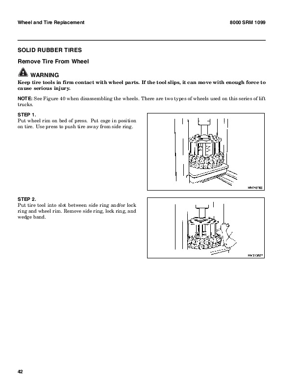
    Solid Rubber Tires Repair…740
      Wheel, Tire Remove…740
      Wheel, Tire Install…742
      SIT Tire, Change for H3.50-5.00XL (G005), and H6.00-7.00XL (F006…743
        Remove SIT Solid Tire From Wheel…744
        Install SIT Solid Tire on Wheel…745
    Adhesives and Sealants…746
    Hydraulic Oil, Lubricant, and Coolant Specifications…747
  tables…666
    Table 1. Maintenance Schedule…676
    Table 2. Hook-Type Carriage Chain Adjustment…728
    Table 3. Pin-Type Carriage Chain Adjustment…728
hyster-897501-12-03-srm0519…750
  toc…750
    Diagrams…750
    Safety Precautions Maintenance and Repair…751
hyster-897800-11-03-srm0590…814
  toc…814
    GM Engines…814
    Safety Precautions Maintenance and Repair…815
    General…818
    Description…818
    Engine Removal and Installation…819
    Cylinder Head Repair…819
      Remove and Disassemble…819
      Clean and Inspect…819
      Valve Guides and Seats, Repairs…820
      Valves, Repair…820
      Valve Seats, Repair…821
      Valve Springs…822
      Rocker Arm Studs (Early Models)…822
      Rocker Arm Studs (Late Models)…823
      Assemble and Install…823
    Cylinder Block Cleaning and Inspection…827
    Piston Bore Preparation…827
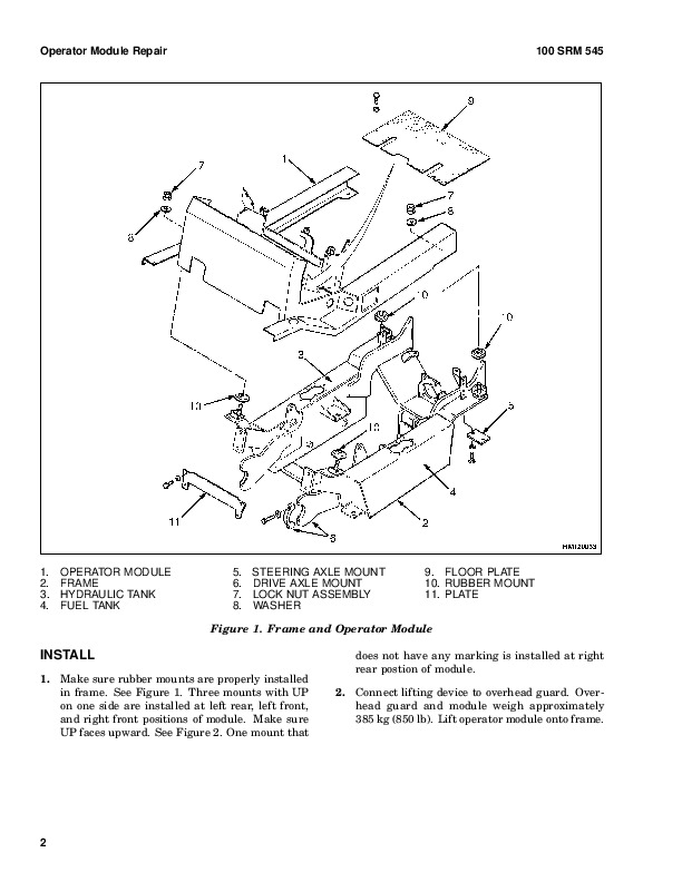
    Engine Mounts Installation…827
    Lubrication System Repair…828
      Oil Pump, Remove and Disassemble…828
      Clean and Inspect…828
      Oil Pump, Assemble and Install…828
      Oil Sump, Install…829
    Timing Cover, Timing Sprockets, Camshaft, and Valve Lifters…830
      Timing Cover…830
        Remove…830
        Install…832
      Timing Sprockets…832
        Remove…832
        Install…832
      Camshaft…833
        Remove…833
        Inspect…833
        Install…833
      Balance Shaft…834
        Remove…834
        Install…835
      Hydraulic Valve Lifters…835
        Remove…835
        Disassemble…836
        Clean and Inspect…836
        Assemble…836
        Install…837
    Crankshaft Repair…838
      Remove…838
      Inspect and Repair…838
      How to Check Clearance Between Main Bearings and Their Journals…839
      Install…840
    Piston and Connecting Rod Assemblies Repair…841
      Connecting Rod Bearings, Replace…841
      Piston and Connecting Rod Assemblies, Remove…842
      Disassemble…842
      Piston, Clean and Inspect…843
      Cylinder Bores, Inspect and Repair…843
      Piston Rings…844
      Assemble…845
      Piston and Connecting Rod Assemblies, Install…845
    Flywheel and Flywheel Housing Repair…846
      Flywheel, Repair…846
      Flywheel, Install…846
        H3.50-5.00XL (H70-110XL), S3.50-5.50XL (S70-120XL), S6.00-7.00XL…846
        H6.00-7.00XL (H135-155XL)…846
      Flywheel Housing H3.50-5.00XL (H70-110XL), H3.50-5.50XM (H70-120…846
      Engine Adapter H6.00-7.00XL (H135-155XL)…846
    Coolant Pump Repair…847
    Thermostat Replacement…847
    Fan Mount Repair (Early Models)…847
    Fan Mount Assembly Repair (Late Models)…847
    Drive Belt Installation…849
    Valve Clearance Adjustment (Early Models)…850
    Valve Clearance Adjustment (New Models)…851
    Compression Check…851
    Engine Specifications…851
      Engine Data…851
      Cylinder Head…852
      Hydraulic Valve Lifter…852
      Camshaft…852
      Pistons…852
      Crankshaft…853
      Connecting Rods…854
      Balance Shaft…854
      Cooling System…854
      Lubrication System…854
    Torque Specifications…855
    Troubleshooting…856
  tables…814
    Table 1. Piston Rings Arrangement on Piston…845
hyster-897934-11-01-srm0626…862
  toc…862
    Cooling System…862
    Safety Precautions Maintenance and Repair…863
    General…866
    Description…867
      Radiator…867
      Radiator Cap…867
      Thermostat…867
      Water Pump…868
      Fan and Fan Shroud…868
    Cooling System Checks…868
      Radiator…868
      Thermostat…868
      Water Pump…869
      Exhaust Leaks…869
      Fan and Fan Shroud…869
    Radiator Cleaning…869
      Drain…869
      Clean…869
      Fill…870
    Troubleshooting…871
hyster-899783-10-03-srm0090…874
  toc…874
    Main Control Valve…874
    Safety Precautions Maintenance and Repair…875
    General…878
    Description…878
    Operation…881
      Lift Spool…881
      Tilt Spool…882
        Tilt Backward…882
        Tilt Forward…883
      Single-Stage Relief Valve…885
      Two-Stage Relief Valve…886
    Main Control Valve Repair…887
      Remove and Disassemble…887
      Clean and Inspect…887
      Assemble…887
      Install…888
    Single-Stage Relief Valve Adjustment…888
    Two-Stage Relief Valve…889
    Auxiliary Control Valve Relief Valve Adjustment (H60-110E Only)…889
    Troubleshooting…890
  tables…874
    Table 1. Relief Pressures (Oil temperature at 55 to 66 C ( 131 t…888
hyster-899784-10-03-srm0002…894
  toc…894
    Alternator with Regulator…894
    Safety Precautions Maintenance and Repair…895
    General…898
    Description…898
    Alternator Repair…900
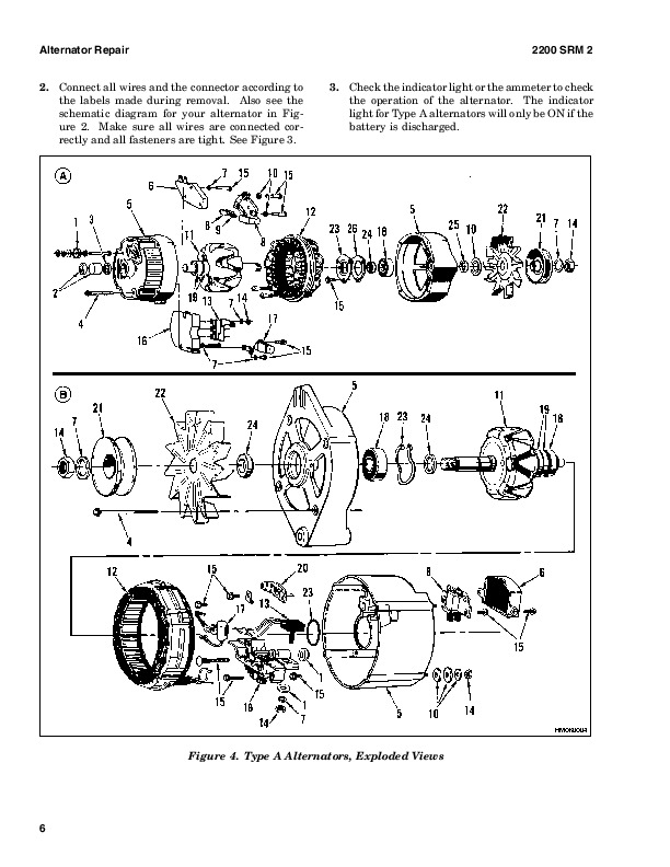
      Alternator Type A…900
        Remove and Disassemble…900
        Clean…901
        Assemble…902
        Install…902
      Alternator Type B…905
        Remove and Disassemble…905
        Clean…905
        Assemble…906
        Install…907
    General Check and Adjustment…908
    Low Output Check (Type A or Type B)…908
    High Output Check (Type A or Type B)…910
    Brushes Circuit Check…911
      Delco Alternators…911
      Motorola Alternators…912
    Diodes Check…913
    Diode Bridge Check…913
      Delco and Leece-Neville Alternators…913
      Motorola Alternators…913
    Rotor Field Winding Check…914
    Stator Windings Check…915
    Voltage Regulator Check…915
    Troubleshooting…915
hyster-910072-11-03-srm0046…920
  toc…920
    Differential…920
    Safety Precautions Maintenance and Repair…921
    General…924
    Description…924
    Differential Repair…924
      Remove…924
        Differential Carrier From Axle Housing, Remove…924
        Differential and Ring Gear From Differential Carrier, Remove…928
        Drive Pinion and Pinion Carrier From Differential Carrier, Remov…930
      Disassemble…931
        Differential and Ring Gear Assembly, Disassemble…931
        Drive Pinion and Pinion Carrier, Disassemble…933
      Clean and Inspect…935
      Assemble…936
        Pinion, Bearings, and Pinion Carrier, Assemble…936
        Pinion Bearings, Adjust Preload…937
          Press Method…937
          Yoke or Flange Method…937
        Triple-Lip Seal, Install…938
        Pinion Carrier Shim Set, Adjust Thickness (Depth of Pinion)…939
        Differential and Ring Gear, Assemble…941
        Differential Gears Rotating Torque, Check…944
        Differential and Ring Gear Assembly, Install…945
        Differential Bearings, Preload Adjust…946
        Ring Gear, Runout Check…947
        Ring Gear Backlash, Adjust…947
        Gear Set, Tooth Contact Pattern Check…949
        Thrust Screw, Install and Adjust…951
      Install…952
        Differential Assembly Into Axle Housing, Install…952
    Specifications…954
    Troubleshooting…958
  tables…920
    Table 1. Ring Gear Backlash Adjustment Specifications…948
    Table 2. Ring and Pinion Tooth Contact Adjustment…950
    Table 3. General Specifications…954
    Table 4. Rivet Installation Pressure…954
    Table 5. Pinion Adjustment…954
    Table 6. Pinion Preload Pressure…955
    Table 7. Torque Specifications…956
    Table 8. Torque Specifications for Metric Hardware…957
    Table 9. Torque Specifications for Metric (Fine) Hardware…957
hyster-910073-09-03-srm0049…962
  toc…962
    Drive Axle…962
    Safety Precautions Maintenance and Repair…963
    General…966
    Description…966
    Drive Axle Repair…967
      Disassemble (Type 1 Shown)…967
      Clean…970
      Inspect…970
      Assemble (Type 1 Shown)…971
    Torque Specifications…974
    Troubleshooting…975
hyster-910076-10-03-srm0054…978
  toc…978
    Steering Control Unit…978
    Safety Precautions Maintenance and Repair…979
    General…982
    Description…982
    Operation…982
    Steering Wheel and Column Assembly Repair…984
    Steering Column Assembly Repair…984
      Type A Steering Column Assembly…984
        Remove and Disassemble…984
        Assemble and Install…986
      Type B Steering Column Assembly…988
        Remove and Disassemble…988
        Assemble and Install…988
        Steering Control Unit…991
          Disassemble…991
          Clean…994
          Assemble…995
    System Air Removal…1000
    Troubleshooting…1000
hyster-910091-10-03-srm0097…1004
  toc…1004
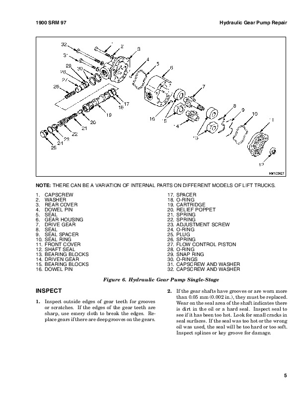
    Hydraulic Gear Pumps…1004
    Safety Precautions Maintenance and Repair…1005
    Description…1008
    Operation…1009
      Flow Control Valve…1009
      Relief Valve…1010
    Hydraulic Gear Pump Repair…1010
      Remove…1010
      Disassemble…1011
      Clean…1011
      Inspect…1012
      Assemble…1015
      Install…1017
    Pump Output Check…1017
      Method No. 1…1017
      Method No. 2…1018
    Hydraulic System Air Check…1019
    Troubleshooting…1020
hyster-910102-10-03-srm0103…1026
  toc…1026
    Tilt Cylinders…1026
    Safety Precautions Maintenance and Repair…1027
    General…1030
    Description…1030
    Tilt Cylinder Repair…1030
      Remove…1030
      Disassemble…1030
      Clean…1030
      Assemble…1031
        Tilt Cylinders With O-Ring or Single-Lip Seals…1031
        Tilt Cylinders for XM and XMS Models…1032
        Tilt Cylinders for H700-800A and Early Model H700-920B…1033
      Install…1034
        Tilt Cylinders Using Chevron Packing…1035
          Install…1036
    Tilt Cylinder Leak Check…1038
    Tilt Cylinder Stroke and Mast Tilt Angle Adjustment…1039
    Torque Specifications…1040
      Piston Rod Nut…1040
      Retainer…1041
    Troubleshooting…1043
  tables…1026
    Table 1. Movement Rates (Maximum) for Tilt Cylinders…1039
hyster-910107-02-01-srm0106…1046
  toc…1046
    Starter…1046
    Safety Precautions Maintenance and Repair…1047
    General…1050
    Description and Operation…1050
    Starter Repair…1052
      Remove…1052
      Disassemble…1052
      Clean…1053
      Assemble…1053
      Install…1054
    General Checks and Adjustments…1054
    Troubleshooting…1057
hyster-910110-12-03-srm0143…1062
  toc…1062
    Instrument Panel Indicators and Senders…1062
    Safety Precautions Maintenance and Repair…1063
    General…1066
    Description…1067
      Steering Column Gauges, Meters, and Indicators…1067
      LED Display Panel…1067
        Battery Discharge Indicators…1067
        Brush Wear Indicators…1074
        Motor Temperature Indicators…1074
      LX Series Display Panel…1076
        Hourmeter Functions…1076
        Battery Indicator Function…1077
        Status Code Function…1078
      ZX Series Display Panels…1078
        Display Panel…1078
        Basic Display Panels…1078
        Performance Display…1081
        Brush Wear Indicators…1084
    Adjustments – General…1085
    Replacement – General Information…1085
    Meter Replacement…1086
    Sender Replacement…1087
      Fuel Level Sender…1087
      Pressure and Temperature Sender…1087
    ITW Display Panel Replacement…1088
      Remove…1088
    Column Mount Display Panel (EV-100/200ZX Motor Controllers) Repl…1089
      Remove…1089
      Display Panel Assembly, Replace…1089
      Indicator LEDs…1090
      Battery Indicators…1090
      Digital Display (Performance Display Panel Only)…1090
      Status Code or Performance Level Switches and Indicator LEDs (Pe…1090
      Basic Display Panel, Replace Parts…1090
      Performance Display Panel, Replace Parts…1092
    Dash Mount Display Panel (EV100/200ZX Motor Controllers) Replace…1093
      Remove and Replace…1093
    Specifications…1093
      Meter Specifications…1093
      Sender Specifications…1094
    Troubleshooting…1094
      Meter…1094
hyster-910119-10-03-srm0135…1098
  toc…1098
    Lift Cylinders…1098
    Safety Precautions Maintenance and Repair…1099
    Safety Procedures When Working Near Mast…1102
    General…1106
    Description…1106
      Lowering Control Valve…1106
      Cylinders (General)…1109
      Cylinders (H520-620B, H700-800A)…1109
        Retainer, Install…1109
      Cylinders (H360-460B)…1111
      Cylinders (Two-Speed)…1113
    Lift Cylinder Repair…1115
      Lift Cylinder Removal Without Removing Mast…1115
        Standard Masts With Main Lift Cylinder Fastened to Crossmember o…1115
        Standard and Full Free-Lift Masts With Lift Cylinder Fastened to…1115
        Masts That Have Two Cylinders, Main Lift Cylinder and Free-Lift …1115
      Disassemble…1117
      Assemble…1117
      Lift Cylinder Installation in Mast…1119
        Standard Masts With Main Lift Cylinder Fastened to Crossmember o…1119
        Standard and Full Free-Lift Masts With Lift Cylinder Fastened to…1119
      Chevron-Style Packing…1119
        Chevron-Style Packing Installation on Piston…1120
        Chevron-Style Packing Installation in Packing Gland…1122
    Lift Cylinders for VISTA® Masts…1123
      Description…1123
        Lowering Control Valve…1123
      Remove…1125
      Disassemble…1126
      Assemble…1127
      Install…1128
        Main Lift Cylinders…1128
        Free-Lift Cylinder…1128
    Lift System Leak Check…1129
    Specifications…1130
    Troubleshooting…1131
  tables…1098
    Table 1. Lift Trucks with Two-Speed Lift Cylinders…1114
    Table 2. Cylinder Retainer Torque Specifications and Weight Guid…1130
hyster-910442-03-03-srm0231…1134
  toc…1134
    Metric and Inch (SAE) Fasteners…1134
    Safety Precautions Maintenance and Repair…1135
    General…1138
      Threaded Fasteners…1138
      Nomenclature, Threads…1138
      Strength Identification…1139
      Cotter (Split) Pins…1139
      Fastener Torque Tables…1144
      Conversion Table…1146
  tables…1134
    Table 1. Bolts and Screws…1140
    Table 2. Studs and Nuts…1141
    Table 3. Torque Nuts…1142
    Table 4. Torque Nuts With Nylon Insert…1143
    Table 5. Torque Values for Metric Fasteners*…1144
    Table 6. Torque Values for Inch Fasteners*…1145
    Table 7. Conversion Table for Metric and English units…1146
    Table 8. Cotter Pin Dimensional Data…1147

Hyster H135-155XL2 (G006) Repair Service Manual


INSTANT DOWNLOAD


Posted on

Hyster H300-360HD, H360HD-EC (F019) & H170-280HD (G007) Repair Service Manual


INSTANT DOWNLOAD


Complete service repair manual with electrical wiring diagrams for Hyster Lift Trucks H300HD-H360HD, H360HD-EC (F019) & H170HD-H280HD (G007), with all the shop information to maintain, diagnose, repair, rebuild like professional mechanics.

Hyster Service Manual H300360HD, H360HDEC (F019) & H170280HD (G007) workshop service & repair manual includes:
* Numbered table of contents easy to use so that you can find the information you need fast.
* Detailed sub-steps expand on repair procedure information
* Numbered instructions guide you through every repair procedure step by step.
* Troubleshooting and electrical service procedures are combined with detailed wiring diagrams for ease of use.
* Notes, cautions and warnings throughout each chapter pinpoint critical information.
* Bold figure number help you quickly match illustrations with instructions.
* Detailed illustrations, drawings and photos guide you through every procedure.
* Enlarged inset helps you identify and examine parts in detail.

1556870 – Hyster Service Manual H300-360HD, H360HD-EC (F019) & H170-280HD (G007).pdf

Total Pages: 1,111 pages
File Format: PDF (Internal Links, Bookmarked, Table of Contents, Searchable, Printable, high quality)
Language: English

Section
Part No.
SRM Number Rev Date
FRAME
1494123
0100 SRM 0927
12/03
OPERATOR’S CAB
1556599
0100 SRM 1100
01/04
PERKINS TIER 2 DIESEL ENGINE – 1100 SERIES (VK)
1541323
0600 SRM 1068
02/04
PERKINS TIER 2 ENGINE ELECTRONIC TROUBLESHOOTING GUIDE
1553764
0600 SRM 1072
01/04
CUMMINS DIESEL ENGINE FAULT CODE GUIDE
1564053
0600 SRM 1101
01/04
COOLING SYSTEM
897934
0700 SRM 0626
11/01
TRANSMISSION
1556600
1300 SRM 1082
01/04
DIFFERENTIAL
910072
1400 SRM 0046
11/03
PLANETARY GEAR AXLE – WET
1494953
1400 SRM 0944
09/03
PLANETARY GEAR AXLE – DRY
1498445
1400 SRM 0945
09/03
STEERING AXLE
897108
1600 SRM 0326
10/03
STEERING SYSTEM
1494140
1600 SRM 0936
09/03
BRAKE SYSTEM – DRY
1494141
1800 SRM 0937
12/03
BRAKE SYSTEM – WET
1498450
1800 SRM 0951
09/03
HYDRAULIC SYSTEM
1494142
1900 SRM 0938
09/03
MAIN CONTROL VALVE
1494955
2000 SRM 0943
09/03
TILT CYLINDERS
910102
2100 SRM 0103
10/03
ALTERNATOR
899784
2200 SRM 0002
10/03
STARTER
910107
2200 SRM 0106
02/01
INSTRUMENT PANEL INDICATORS AND SENDERS
1556871
2200 SRM 1105
01/04
MASTS AND CARRIAGES (STARTING 2003)
1553599
4000 SRM 1062
02/04
EMPTY CONTAINER HANDLING ATTACHMENT
1503241
5000 SRM 0969
09/03
INCH (SAE) and METRIC FASTENERS
910442
8000 SRM 0231
03/03
CAPACITIES and SPECIFICATIONS
1494145
8000 SRM 0940
10/03
PERIODIC MAINTENANCE
1556602
8000 SRM 1099
02/04
DIAGRAMS
1556604
8000 SRM 1103
01/04
 

PART NO. 1556870

Rev. 02/04

    Frame….2
    Safety Precautions Maintenance and Repair….3
    General….6
    Description….6
    Counterweight Repair….6
      Remove….6
      Install….8
      Fenders….8
        Remove….8
        Install….8
      Side Counterweights H13.00-16.00XM (H300-360HD)….8
      Side Counterweight, Replace….8
    Hood and Air Cleaner Repair….9
      Remove….9
      Install….10
    Hydraulic Tank Repair….11
      Remove….11
      Repairs, All Units….13
        Small Leaks….13
        Large Leaks….13
      Clean….13
        Steam Method….13
        Chemical Solution Method….14
      Other Methods of Preparation for Repair….14
      Install….14
    Fuel Tank Repair….15
      Remove….15
      Repairs….15
      Install….15
    Cooling System and Radiator Repair….17
      Remove….17
      Install….17
    Engine and Transmission Repair….20
      Hyster T-50 Transmission, Remove….20
      Hyster T-50 Transmission, Install….21
      TE-10 Transmission….22
        Remove….22
        Install….25
    Label Replacement….27
hyster-1494140-09-03-srm0936….32
  toc….32
    Steering System….32
    Safety Precautions Maintenance and Repair….33
    General….36
    Description….36
    Steering Wheel and Column Assembly….38
      General….38
      Steering Wheel and Horn….38
        Remove….38
        Install….38
    Steering Control Unit Repair….40
      General….40
      Description….40
      Operation….40
      Remove….41
      Disassemble….41
      Clean….44
      Assemble and Install….44
    Steering System Air Removal….50
    Steering Relief Pressure Check….51
    Troubleshooting….51
hyster-1494141-12-03-srm0937….56
  toc….56
    Dry Brake System….56
    Safety Precautions Maintenance and Repair….57
    General….60
    Description….60
    Operation….61
      Service Brakes….61
      Parking Brake….61
    Air Tank Repair….64
      Relief Valve….64
      Drain Valve….64
    Brake Pedal Valve Repair….65
      Remove….65
      Disassemble, Inspect, and Assemble….65
      Install….66
    Air Chambers Repair….66
      Remove….66
      Disassemble….66
      Inspect….67
      Assemble….68
      Install….68
    Actuator Arms Repair….69
      Remove….69
      Inspect….69
      Install….69
    Brake Assemblies Repair….70
      Brake Shoe, Remove….70
      Camshaft, Remove….72
      Clean….72
      Inspect….73
      Camshaft, Install….73
      Brake Shoe, Install….74
    Air Dryer….75
      Description….75
      Cartridge….75
        Remove….75
        Install….75
      Filter….75
        Remove….75
        Install….75
    Quick-Release Valve….77
    Governor Check and Adjustment for Air Compressor….77
    Brake Shoes Adjustment….78
    Specifications….79
    Troubleshooting….80
      Service Brakes….80
      Service Brakes, Park Function ….82
  tables….56
    Table 1. Air Chambers Operation….63
hyster-1494142-09-03-srm0938….86
  toc….86
    Hydraulic System….86
    Safety Precautions Maintenance and Repair….87
    General….90
    Description and Operation….90
      Hydraulic Pump….90
      Main Control Valve….90
      Steering Control Unit….91
      Pilot Block….91
      Tilt Relief Valve….91
    Hydraulic Pump Repair….91
      Remove….91
      Disassemble….92
      Clean and Inspect….92
      Assemble….92
      Install….92
    Priority Valve Repair….94
      Remove….94
      Install….94
    Pilot Valve Repair….95
      Remove….95
      Disassemble….96
      Clean and Inspect….96
      Assemble….96
      Install….96
    Control Levers and Joystick Repair….97
      Remove….97
      Install….97
    Pump Output Check….97
      First Method….97
      Second Method….98
    Steering Relief Pressure Check and Adjustment….99
    Calibration Procedure for Hydraulic Controls….100
      General and Calibration Startup….100
      Joystick/Lever Calibration….102
        Levers….102
        Joystick….103
      Valve Flow Adjustment….103
      PWM Board Readouts/PV3 Readouts….104
      I/O Board Readouts….104
      Diagnostics….105
      Calibration System Shutdown….105
    Diagnostics….105
    Specifications….109
    Troubleshooting….109
      Lift, Lower, Tilt, and Attachment Circuits (Also see Main Contro….110
      Steering Circuit (Also see Steering System 1600 SRM 936 )….111
  tables….86
    Table 1. Error Code Display….105
    Table 2. Altering PT FLT (Old Logic)….107
    Table 3. Altering PT FLT (New Logic)….107
    Table 4. Fixed PT Logic….108
    Table 5. ECH….108
hyster-1494145-10-03-srm0940….122
  toc….122
    Capacities and Specifications….122
    Safety Precautions Maintenance and Repair….123
    Lift Truck Weights….126
    Capacities….126
    Engine Specifications….127
      Perkins Diesel….127
      Cummins Diesel….128
    Hydraulic System….129
      Perkins….129
    Electrical System….129
    Tire Sizes….130
    Mast Speeds….130
      Perkins Diesel….130
      Cummins Diesel….131
    Torque Specifications, Cummins Diesel….131
      Lubrication System….131
    Torque Specifications, Perkins Diesel….132
      Engine….132
        Cylinder Head Assembly….132
        Piston and Connecting Rod Assemblies….132
        Crankshaft Assembly….132
        Timing Case and Drive Assembly….132
        Turbocharger….132
        Lubrication System….132
        Fuel System….132
        Cooling System….133
        Flywheel and Housing….133
        Aspiration System….133
        Electrical Equipment….133
        Auxiliary Equipment….133
    Torque Specifications – Perkins, Tier 2….133
      Cylinder Head Assembly….133
      Piston and Connecting Rod Assemblies….134
      Crankshaft Assembly….134
      Timing Case and Drive Assembly….134
      Turbocharger….134
      Lubrication System….134
      Fuel System….134
      Cooling System….134
      Flywheel….135
      Auxiliary Equipment….135
    Torque Specifications, General….135
      Transmission….135
      Driveline and Axle….135
      Differential….135
      Brakes – Wet….135
      Brakes – Dry….135
      Steering….135
      Hydraulic System….136
      Mast….136
      Carriage….136
      Tilt Cylinders….136
      Frame….136
      Wiper Arms, Front….137
    Hyster T-50 Transmission Pressures (Powershift and Automatic)….137
    TE-10 Transmission Specifications….138
      Electrical….138
      Hydraulic Cooler Lines….138
      Torque Specifications for Lubricated or Plated Screw Threads….139
  tables….122
    Table 1. Temperature Sensor (In Speed Sensor) Resistance Versus ….138
    Table 2. Grade 5….139
    Table 3. Grade 8….139
    Table 4. Grades 8.8, 10.9, and 12.9….139
    Table 5. O-ring Port Plug Torque Chart….140
    Table 6. Pipe Plug Torque Chart….140
hyster-1494953-09-03-srm0944….144
  toc….144
    Planetary Drive Axle….144
    Safety Precautions Maintenance and Repair….145
    General….148
    Description….148
    Operation….150
      Identification….150
    Removal….151
    Disassembly….151
      Planetary Spider and Gearing Assembly H8.00-12.00XM (H170-280HD)….151
      Planetary Spider and Gearing Assembly H13.00-16.00XM (H300-360HD….153
      Wheel End….155
      Spindle and Piston Housing….156
    Cleaning….157
      Clean Ground or Polished Parts….157
      Clean Parts With Rough Finish….157
      Clean Axle Assemblies….157
      Drying Cleaned Parts….157
    Corrosion Prevention….157
    Parts Inspection….158
      Tapered Roller Bearings….158
      Bevel Pinion and Ring Gear Sets….159
      Main Differential Assembly….159
      Axle Shafts….159
      Yoke….159
      Brakes….159
      Repair or Replace Parts….159
      Repair Welding….159
      Apply Silicone Gasket Material….160
    Assembly….160
      Spindle and Piston Housing to Axle Housing….160
      Wet Disc Brakes….161
      Adjust Wheel Bearing Preload….162
      Planetary Spider and Gearing Assembly H8.00-12.00XM (H170-280HD)….163
      Planetary Spider and Gearing Assembly H13.00-16.00XM (H300-360HD….163
      Planetary Spider Assembly….164
    Installation….165
      Fill Wet Disc Brakes With Hydraulic Fluid….165
    Torque Specifications….166
    Lubrication Specification….167
hyster-1494955-09-03-srm0943….170
  toc….170
    Main Control Valve….170
    Safety Precautions Maintenance and Repair….171
    General….174
    Description….174
    Operation….177
      Lift Section….177
      Tilt/Auxiliary Section….177
      Relief Valves….177
      Unloader Valve….177
    Main Control Valve Repair….180
      Remove….180
      Disassemble….180
        Auxiliary Side….180
        Lift Side….180
      Clean and Inspect….181
      Assemble….181
        Auxiliary Side….181
        Lift Side….183
      Install….183
    Pressure Relief Valve Check and Adjustment….184
      Check and Adjust….184
      Replace….184
    Specifications….185
    Troubleshooting….185
hyster-1498445-09-03-srm0945….190
  toc….190
    Planetary Drive Axle….190
    Safety Precautions Maintenance and Repair….191
    General….194
    Description….194
    Operation….196
      Identification….196
    Removal….197
    Disassembly….197
      Brake Drum….197
      Planetary Spider and Gearing Assembly H8.00-12.00XM (H170-280HD)….198
      Dry Brakes….200
      Planetary Spider and Gearing Assembly H13.00-16.00XM (H300-360HD….200
      Spindle and Brake Spider….202
    Cleaning….203
      Ground or Polished Parts….203
      Parts With Rough Finish….203
      Axle Assemblies….203
      Drying Cleaned Parts….203
    Corrosion Prevention….203
    Parts Inspection….204
      Tapered Roller Bearings….204
      Bevel Pinion and Ring Gear Sets….205
      Main Differential Assembly….205
      Axle Shafts….205
      Yoke….205
      Brakes….205
      Repair or Replace Parts….205
      Repair Welding….205
      Apply Silicone Gasket Material….206
    Assembly….206
      Spindle, Brake Spider, and Brake….206
      Wheel End….207
      Adjust Wheel Bearing Preload….208
      Planetary Spider and Gearing Assembly H8.00-12.00XM (H170-280HD)….209
      Planetary Spider and Gearing Assembly H13.00-16.00XM (H300-360HD….209
      Planetary Spider Assembly….210
    Installation….211
    Torque Specifications….212
    Lubrication Specification….213
hyster-1498450-09-03-srm0951….216
  toc….216
    Wet Brake System….216
    Safety Precautions Maintenance and Repair….217
    General….220
    Description and Operation….220
      Service Brakes….220
      Parking Brake….220
      Oil Cooler Circuit….220
    Pressure Switch Replacement….224
    Accumulators Replacement….224
    Brake Treadle Valve Repair….224
      Remove and Disassemble….224
      Clean and Inspect….225
      Assemble and Install….225
    Parking Brake Valve Repair….225
      Remove….225
      Clean and Inspect….225
      Repair….225
      Install….225
    Parking Brake Caliper Repair….226
      Remove….226
      Disassemble….228
      Inspect….228
      Install….228
      Adjust….228
    Brake Pad Repair….229
      Inspect….229
      Remove….229
      Install….229
    Seals Repair….229
      Remove….229
      Install….230
    Service Brake Repair….230
      Remove and Disassemble….230
        Drain Lubricating Oil….230
        Drain Coolant Oil….236
        Disconnect Brake Lines….236
        Wheel End With Outer Bearing on Ring Gear Hub Journal H13.00-16….236
        Wheel End With Outer Bearing on Spindle Journal H8.00-12.00XM (H….237
        Brake Disc Housing Assembly Wheel End….238
        Brake Piston Housing….239
        Brake Piston Housing and Wheel Spindle….240
      Inspect….240
      Clean….242
      Assemble….243
        Wheel Spindle….243
        Brake Piston Housing….243
        Piston Assembly….245
        Brake Disc Housing….245
        Duo-Cone Face Seal Into Brake Disc Housing and Into Hub….247
        Check for Correct Installation of Duo-Cone Seal….248
        Wheel Hub to Brake Disc Housing….249
      Adjust….250
        Fill Brake System With Coolant Oil….250
        System Air Removal….251
        Adjust Brake With New Disc Pack….251
        Coolant Change Intervals….252
        Coolant Draining and Filling….252
    Specifications….254
      Minimum Brake Disc Thickness….257
      Hydraulic Fluid for Brake Actuation….257
      Brake Coolant Specifications….257
      Coolant Change Intervals….257
      Hydraulic Fluid Specifications….257
    Troubleshooting….257
      Brake Does Not Apply….257
      Brake Does Not Release….258
      Brake Performance….258
      Brake Leaks Actuation Fluid….259
      Brake Cooling Fluid Leakage….260
      Brake Noise and Vibration….260
      Brake Overheats….260
  tables….216
    Table 1. Brake Pad Adjustment….228
    Table 2. Minimum Brake Disc Thickness….241
    Table 3. Formed Seal Wear Chart….241
hyster-1503241-09-03-srm0969….264
  toc….264
    Empty Container Handling Attachment….264
    Safety Precautions Maintenance and Repair….265
    General….268
    Description….268
    Operation….268
      General….268
      Selector Valves….268
      Sideshift Circuit….268
      Extend and Retract Circuit….273
      Twist Lock Circuit and Control….273
        Model 553 – Horizontally Mounted….273
        Model 558 – Vertically Mounted….275
      Lifting Hooks….275
        Model 555….275
      Indicator Lights and LEDs….276
      Lift Interrupt and Override….276
      Overlowering Interrupt and Override….276
    Carriage and Attachment Repair….277
      Remove….277
    Attachment Without Carriage Repair….277
      Remove….277
    Sideshift Cylinders Repair….278
      Remove….278
      Disassemble….278
      Assemble….278
    Extension Cylinders Repair….279
      Remove….279
      Disassemble….279
      Clean and Inspect….279
      Assemble….279
      Install….279
    Vertical End Beams Repair….281
      Remove….281
      Install….281
      Hose Replacement in End Beams….281
    Twist Locks Repair for Model 553….282
      Remove….282
      Disassemble….282
      Clean and Inspect….282
      Assemble….282
    Hooks Replacement for Model 555….283
      Inspect….283
      Remove….283
      Install….283
    Twist Locks Repair for Model 558….284
      Disassemble….284
      Clean and Inspect….284
      Assemble….285
    Bleed the System….285
    Valve Assembly….286
    Slide Pad Replacement….286
    Adjustments….287
      Twist Lock Angle Adjustment….287
        Model 558 Only….287
      LOCKED/NOT LOCKED Sensors Adjustment….287
        Model 553….287
        Model 558….288
      Seated Sensor Adjustment….288
        Model 553….288
        Model 558….288
      Overlowering Protection Sensor Adjustment (Models 553 and 558)….288
      Torque Chart….289
    Maintenance….289
      Additional Attachment Maintenance….291
      Interface Boxes….292
        Model 555….292
        Models 553 and 558….292
    Troubleshooting….294
  tables….264
    Table 1. Torque Chart….289
    Table 2. Maintenance Schedule….290
hyster-1541323-02-04-srm1068….310
  toc….310
    Perkins Tier 2 Diesel Engines….310
    Safety Precautions Maintenance and Repair….311
    General….318
      General Safety Rules….318
    Description….319
      Engine Serial Number Codes….321
      Engine Data….321
    Engine Removal and Installation….322
    Cylinder Head Assembly Repair….322
      Valve Cover….322
        Remove….322
        Install….323
      Rocker Arm Assembly….323
        Remove….323
        Disassemble….323
        Inspect….323
        Assemble….323
        Install….323
      Valve Clearance Adjustments….324
      Valve Springs….325
      Cylinder Head Assembly….326
        Remove….326
        Install….328
      Valves and Valve Springs….331
        Remove….331
        Inspect….331
        Install….332
      Valve Guides….332
        Inspect….332
        Remove….332
        Install….332
      Cylinder Head and Valve Seats….333
        Inspect….333
        Repair….334
        New Valve Seats, Install….334
    Piston and Connecting Rod Assemblies Repair….334
      Rod Bearings….335
        Remove….335
        Install….335
      Piston and Connecting Rod Assembly….336
        Service Note….336
        Remove….336
        Install….337
      Piston Rings….338
        Remove….338
        Inspect….338
        Install….339
      Piston and Connecting Rod….339
        Disassemble….339
        Inspect….339
        How to Select Correct Replacements….340
        Install….341
      Piston Cooling Jets….341
        Remove….341
        Install….342
    Crankshaft Assembly Repair….342
      General….342
      Crankshaft Pulley….343
        Remove….343
        Inspect….343
        Install….343
      Rear Oil Seal….344
        Remove….344
        Install….344
      Main Bearings….345
        Remove….345
        Inspect….346
        Install….346
      Thrust Washers….346
        Crankshaft Axial Movement, Check….346
        Remove….347
        Install….347
      Crankshaft….348
        Remove….348
        Inspect….348
        Install….349
      Flywheel….350
        Remove….350
        Ring Gear, Replace….350
        Install….350
      Flywheel Housing….351
        Remove….351
        Install….351
    Timing Case and Timing Gears Repair….352
      General….352
      Timing Case Cover….352
        Remove….352
        Install….353
      Front Oil Seal….353
        Remove….353
        Install….353
      Crankshaft Pulley Wear Sleeve….354
        Install….354
      Idler Gear and Hub….354
        Remove….354
        Install….355
      Air Compressor Drive, Bendix….356
        Disassemble….356
        Assemble….356
      Fuel Injection Pump Gear….357
        Remove….357
        Install….358
      Camshaft Gear….358
        Remove….358
        Install….359
      Crankshaft Gear….359
        Remove….359
        Install….360
      Timing Case….360
        Remove….360
        Install….360
      Camshaft and Tappets….361
        Remove….361
        Install….362
    Cylinder Block Assembly Repair….362
      Description….362
      Cylinder Block….362
        Disassemble….362
        Inspect….363
        Assemble….363
      Cylinder Liner….364
        Inspect….364
        Cylinder Liner Condition, Check….364
        Remove….365
        Service Liner, Install….366
        Partially Finished Liner, Install….367
    Engine Timing….368
      Description….368
        How to Set Number One Piston to TDC on Compression Stroke….369
        How to Set Number One Piston to TDC on Compression Stroke (Alter….370
        How to Set Number One Piston to 4° After TDC on Compression Stro….371
        Valve Timing, Check….372
        Fuel Injection Pump Timing, Check….373
    Turbocharger….373
      General….373
      Remove….373
      Install….374
      Impeller and Compressor Housing, Clean….374
      Waste-Gate Valve Check….375
      Closed Circuit Breather System (CCB)….376
        CCB Assembly, Remove….376
        Closed Circuit Drain Valve, Remove….376
        CCB Assembly, Install….376
        Closed Circuit Drain Valve, Install….376
    Lubrication System Repair….377
      General….377
      Oil Filter, Replace….377
      Oil Filter Head….377
        Remove….377
        Install….377
      Oil Filter Head Bypass Valve….378
        Remove and Install….378
      Oil Sump….378
        Remove….378
        Install….378
      Oil Pump….379
        Remove….379
        Inspect….379
        Install….380
      Relief Valve….381
        Remove….381
        Disassemble….381
        Inspect….381
        Assemble….381
        Install….381
      Idler Gear Shaft, Replace….381
        Remove….382
        Remove (Alternative)….382
        Install….383
        Install (Alternative)….383
    Fuel System Repair….384
      Description….384
      Fuel Injection Pump….386
        Remove….386
        Install….388
      Fuel System Air Removal….389
      Fuel Filter, Replace….391
      Fuel Injectors….391
        Remove….392
        Inspect….392
        Install….392
      Fuel Lift Pump….393
        Remove….393
        Disassemble….393
        Assemble….393
        Install….394
        Test….394
    Cooling System Repair….395
      General….395
      Thermostat….395
        Remove….395
        Install….396
        Test….396
      Coolant Pump….396
        Remove….396
        Disassemble….397
        Assemble….399
        Install….401
      Fan and Fan Drive….402
        Remove….402
        Install….402
      Oil Cooler….402
        Remove….402
        Disassemble and Assemble….403
        Install….403
    Electrical Equipment Repair….404
      Drive Belts….404
      Alternator….404
        Remove….404
        Install….404
      Electronic Control Module (ECM)….405
        Remove….405
        Inspect….405
        Install….405
      Voltage Load and Protection Module (VLPM)….406
        Remove….406
        Install….406
      Engine Speed and Timing Sensor….406
        Remove….406
        Install….407
      Pressure Sensors (Engine Oil and Air Intake)….407
        Remove….407
        Install….408
      Temperature Sensor….408
        Remove….408
        Install….409
      Starter Motor….409
        Remove….409
        Install….409
      Cold Start Aid….409
    Air Compressor….409
      General….409
      Repair….410
        Remove….410
        Install….410
    Rotary Exhauster Replacement….411
      Remove….411
      Clean….411
      Install….411
    Engine Specifications….412
      Cylinder Head Assembly….412
      Piston and Connecting Rods….415
      Crankshaft Assembly….416
        Crankshaft Overhaul….417
      Timing Case and Drive Assembly….419
      Engine Block Assembly….420
      Turbocharger….421
      Lubrication System….422
      Cooling System….424
      Flywheel and Housing….424
      Electrical Equipment….424
    Torque Specifications….425
      Cylinder Head Assembly….425
      Piston and Connecting Rod Assemblies….425
      Crankshaft Assembly….425
      Timing Case and Drive Assembly….425
      Turbocharger….425
      Lubrication System….425
      Fuel System….425
      Cooling System….426
      Flywheel….426
      Auxiliary Equipment….426
    Special Torque Specifications….426
      Flywheel and Housing….426
      Electrical Equipment….426
      Auxiliary Equipment….426
    Special Tools….427
    Troubleshooting….432
    Turbocharger Troubleshooting….434
  tables….310
    Table 1. Cylinder Head….412
    Table 2. Valve Guides….412
    Table 3. Inlet Valves….413
    Table 4. Exhaust Valves….413
    Table 5. Valve Springs….414
    Table 6. Tappets….414
    Table 7. Rocker Arm Shaft….414
    Table 8. Rocker Arms and Bushings….414
    Table 9. Pistons….415
    Table 10. Piston Rings….415
    Table 11. Piston Pins….415
    Table 12. Connecting Rods….415
    Table 13. Small End Bushings….416
    Table 14. Connecting Rod Bearings….416
    Table 15. Piston Cooling Jets….416
    Table 16. Crankshaft….416
    Table 17. Main Bearings….417
    Table 18. Crankshaft Thrust Washers….417
    Table 19. Crankshaft Heat Treatment….417
    Table 20. Crankshaft Overhaul Specifications….417
    Table 21. Maximum Variation (Run-Out)….419
    Table 22. Camshaft….419
    Table 23. Camshaft Thrust Washer….419
    Table 24. Camshaft Gear….419
    Table 25. Gear for Fuel Injection Pump….419
    Table 26. Crankshaft Gear….420
    Table 27. Idler Gear and Hub….420
    Table 28. Cylinder Block….420
    Table 29. Cylinder Liners….420
    Table 30. Cylinder Liner Specifications (Partially Finished)….421
    Table 31. Oil Pump….422
    Table 32. Idler Gear for Oil Pump….422
    Table 33. Relief Valve….422
    Table 34. Oil Filter….422
    Table 35. Bosch Fuel Injection Pump….422
    Table 36. Fuel Injector Codes….423
    Table 37. Fuel Pump….424
    Table 38. Fuel Filter….424
    Table 39. Coolant Pump….424
    Table 40. Thermostat….424
    Table 41. Fan Drive Housing….424
    Table 42. Limits for Flywheel Run Out and Alignment (Total Indic….424
    Table 43. Alternator….424
    Table 44. Starter Motor….424
    Table 45. Cold Start Aid….424
    Table 46. List of Possible Causes….432
    Table 47. List of Possible Causes….434
hyster-1553599-02-04-srm1062….438
  toc….438
    Masts and Carriages….438
    Safety Precautions Maintenance and Repair….439
    General….442
    Description….442
    Operation….443
      Two-Stage Mast….443
      Three-Stage Mast….443
    Safety Procedures When Working Near Mast….445
    Forks Repair….447
      Remove….447
      Inspect and Adjust….447
      Install….448
    Carriage Repair….448
      Description….448
        Three Function….448
        Four to Six Function….448
      Remove….448
      Disassemble….451
      Clean and Inspect….451
      Assemble….451
      Install….452
    Sideshift Cylinder Repair….452
      Remove….452
      Disassemble….452
      Clean and Inspect….455
      Assemble….455
      Install….456
    Fork Positioner Cylinders Repair….456
      Remove….456
      Disassemble….456
      Clean and Inspect….456
      Assemble….456
      Install….456
    Directional Control Valve Repair….462
      Remove….462
      Disassemble….463
      Clean and Inspect….463
      Assemble….463
      Install….463
    Mast Repair….464
      Two- and Three-Stage Mast….464
        Remove….464
        Disassemble….469
        Clean and Inspect….469
        Assemble….471
        Install….472
      Three-Stage Mast (Four Cylinders)….473
        Remove….473
        Disassemble….475
        Clean and Inspect….475
        Assemble….475
        Install….477
      Fork Carriage Chains….479
        Adjust….479
      Bearing Rollers….481
        Description….481
        Lubrication….481
        Clearance….481
        Remove and Disassemble….481
        Assemble….481
      Mast Profile….482
    Lift Cylinders Description….482
      Piston-Type Cylinders….482
      Displacement-Type Cylinders….482
    Lift Cylinders Repair….483
      Remove….483
      Disassemble….485
      Clean and Inspect….485
      Assemble….485
      Install….486
    Mast Operation Check….486
    Lift and Tilt System Leak Checks….487
      Lift System….487
      Tilt System….487
    Tilt Cylinder Stroke and Backward Tilt Angle Adjustment….488
    Lift Chain Adjustments….488
    Mast Adjustments….489
      Bearing Blocks, Two Stage Masts….489
      Wear Plates….489
    Carriage Adjustment….489
    Troubleshooting….491
  tables….438
    Table 1. Allowable Mast Movement from Internal Leakage….487
hyster-1553764-01-04-srm1072….496
  toc….496
    Perkins Tier 2 Diesel Engine Electronic Troubleshooting Guide….496
    Safety Precautions Maintenance and Repair….497
    Electronic Troubleshooting….520
      System Operation….520
      Electronic Controls….520
      Engine Governor….521
      Timing Considerations….521
      Fuel Injection….521
      Diagnostic Codes….521
      Diagnostic Fault Codes….521
      Diagnostic Event Codes….521
      Programmable Parameters….522
      Passwords….522
      Electronic Service Tools….522
      Electronic Service Tool (EST)….522
        Connecting the Electronic Service Tool and the Communication Ada….522
        Support for the Electronic Service Tool….523
        Optional Service Tools….523
      Diagnostic Codes….523
      Indicator Lamps….526
      Replacing the ECM….527
      Self Diagnostics….528
    Glossary….529
    Sensors and Electrical Connectors….533
    Engine Wiring Information….536
      Harness Wire Identification….539
    Diagnostic Code Reader….539
      General….539
      Reference Documents….539
      Abbreviations….539
      Environmental Specification….539
      Hardware….539
        Connection Cable….541
      Software….541
        Engine Communication….541
      User Controls….541
        Power Supply….541
        Display Screen….542
        Operation Controls….542
        Audible Warning….542
      Operation Instructions….542
        How to Connect the Diagnostic Code Reader to the Engine….542
        How to Turn ON the Diagnostic Code Reader….542
        How to use the Display Screen….542
        How to Operate the Diagnostic Code Reader….543
          Main Menu….543
          Active Codes….543
          Inactive Codes….543
          How to Clear Codes….544
          Status Lamp….544
          Data List….545
      Diagnostics….545
    Programming Parameters….546
      Passwords….546
      Factory Passwords….546
      Customer Passwords….547
      Flash Programming….547
      Flash Programming a Personality Module….547
      WinFlash Error Messages….547
    System Configuration Parameters….548
      Full Load Setting….548
      Full Torque Setting….548
      Rating Interlock….548
      Engine Serial Number….548
      ECM Software Release Date….548
    Troubleshooting Without A Diagnostic Code….549
      Alternator Noise (Noisy Operation)….549
        Probable Causes….549
        Recommended Actions….549
          Alternator Drive Belts….549
          Alternator Drive Pulley….549
          Alternator Bearings….549
      Alternator Will Not Charge (Charging Problem)….549
        Probable Causes….549
        Recommended Actions….549
          Alternator Drive Belts….549
          Charging Circuit….549
          Alternator or Regulator….549
      Battery….549
        Probable Causes….549
        Recommended Actions….549
          Faulty Battery….549
          Auxiliary Device….549
      Cannot Reach Top Engine RPM….549
        Probable Causes….550
        Recommended Actions….550
          Diagnostic Codes….550
          Fuel Supply….550
          Air Intake and Exhaust System….550
          Individual Malfunctioning Cylinders….550
          Valve Lash….550
          Check for Low Compression….550
          Check the Fuel Injection Nozzles….551
          Check the Turbocharger….551
          ECM Parameters….551
          Check the Signal for the Throttle Position Sensor….551
      Coolant in Engine Oil….551
        Probable Causes….551
        Recommended Actions….551
          Engine Oil Cooler Core….551
          Cylinder Head Gasket….551
          Cylinder Head….552
          Cylinder Block….552
      Coolant Temperature Is Too High….552
        Probable Causes….552
        Recommended Actions….552
          Radiator Fins….552
          Coolant Level….552
          Radiator Cap and/or Pressure Relief Valve….552
          Combustion Gases in the Cooling System….552
          Water Temperature Regulator….552
          Restriction in the Coolant System….552
          Coolant Temperature Gauge….552
          Coolant Pump….552
          Excessive Load on the System….552
      ECM Will Not Accept Factory Passwords….553
        Probable Causes….553
        Recommended Actions….553
      ECM Will Not Communicate with Other Systems or Display Modules….553
        Probable Causes….553
        Recommended Actions….553
      Electronic Service Tool Will Not Communicate with ECM….553
        Probable Causes….553
        Recommended Actions….553
      Engine Cranks but Will Not Start….554
        Probable Causes….554
        Recommended Actions….554
          Diagnostic Codes….554
          Visual Checks….554
          Crank Without Injection….554
          Starting Motor Solenoid or Starting Circuit….554
          Valve Lash….554
          Fuel Injection Nozzles….554
          Air Inlet Heater Starting Aid….555
          Air Intake and Exhaust System….555
          Low Compression….555
          Fuel Supply….555
      Engine Has Early Wear….555
        Probable Causes….555
        Recommended Actions….555
          Dirt in Engine Oil….555
          Leaks in Air Intake System….555
          Low Oil Pressure….555
      Engine Misfires, Runs Rough or Is Unstable….556
        Probable Causes….556
        Recommended Actions….556
          Logged Codes….556
          Fuel Supply….556
          Air Intake and Exhaust System….556
          Individual Malfunctioning Cylinders….556
          Valve Lash….556
          Check for Low Compression….556
          Check the Fuel Injection Nozzles….557
          Check the Air Inlet Heater Starting Aid….557
          Check the Engine Speed/Timing Sensors….557
          Check the Signal for the Throttle Position Sensor….557
          Check the Fuel Injection Pump….557
      Engine Oil in Cooling System….557
        Probable Causes….557
        Recommended Actions….557
          Engine Oil Cooler Core….557
          Cylinder Head Gasket….558
          Cylinder Head….558
      Engine Speed Does Not Change….558
        Probable Causes….558
        Recommended Repairs….558
          Diagnostic Codes….558
      Engine Stalls at Low RPM….558
        Probable Causes….558
        Recommended Actions….558
          Diagnostic Codes….558
          Fuel Injection Nozzles….558
          Fuel Supply….558
          Accessory Equipment….559
          Power Mode Control….559
      Engine Vibration….559
        Probable Causes….559
        Recommended Actions….559
          Engine Supports….559
          Malfunctioning Individual Cylinder….559
          Valve Lash….559
          Check for Low Compression (cylinder pressure)….559
          Check the Fuel Injection Nozzles….559
          Turbocharger….560
      Engine Will Not Crank….560
        Probable Causes….560
        Recommended Repairs….560
          Machine Security System….560
          Battery Cables and/or Batteries….560
          Starting Motor Solenoid or Starting Circuit….560
          Starting Motor and/or Flywheel Ring Gear….560
          Electrical Power Supply….560
          Internal Engine Problem….560
      Excessive Black Smoke….561
        Probable Causes….561
        Recommended Actions….561
          Air Intake System or Exhaust System….561
          Individual Malfunctioning Cylinder….561
          Valve Lash….561
          Low Compression (cylinder pressure)….561
          Check the Fuel Injection Nozzles….561
          Check the Turbocharger….561
          Broken 5-Volt Supply Wire….562
          Verifying the ECM Software….562
      Excessive Engine Oil Consumption….562
        Probable Causes….562
        Recommended Actions….562
          Oil Level….562
          Engine Crankcase Breather….562
          Air Intake and Exhaust System….562
          Turbocharger….562
          Low Compression (cylinder pressure)….563
      Excessive Valve Lash….563
        Probable Causes….563
        Recommended Actions….563
          Lubrication….563
          Valve Lash….563
          Valve Train Components….563
      Excessive White Smoke….563
        Probable Causes….563
        Recommended Actions….563
          Fuel Supply….563
          Individual Malfunctioning Cylinder….564
          Valve Lash….564
          Low Compression (cylinder pressure)….564
          Air Inlet Heater Starting Aid….564
          Fuel Injection Nozzles….564
          Coolant Temperature Sensor Circuit….564
          Engine Pressure Sensors….564
      Intake Air Temperature Is Too High….564
        Probable Causes….564
        Recommended Repairs….564
          High Ambient Air Temperature….564
          Coolant Temperature….565
          Check for High Intake Air Restriction and/or High Altitude….565
          Intake Air Restriction….565
          High Altitude….565
          Check the Intake Manifold Air Temperature Sensor and/or the Circ….565
          Check for Sufficient Coolant Flow Through the Aftercooler (if eq….565
          Check for Sufficient Flow of Air Through the Aftercooler (if equ….565
      Intermittent Engine Shutdown….565
        Probable Causes….565
        Recommended Actions….565
          Logged Codes….565
          Fuel Supply….565
          Engine Protection Device….566
          Electrical Connectors….566
      Intermittent Low Power or Power Cutout….566
        Probable Causes….566
        Recommended Repairs….566
          Diagnostic Codes….566
          Electrical Connectors….566
          Fuel Supply….566
          Check the Intake Manifold Pressure….567
          Air Intake and Exhaust System….567
          Individual Malfunctioning Cylinders….567
          Valve Lash….567
          Check for Low Compression….567
          Check the Fuel Injection Nozzles….567
          Check the Turbocharger….568
          ECM Parameters….568
          Electronic System Problem….568
      Low Engine Oil Pressure….568
        Probable Causes….568
        Recommended Actions….568
          Engine Oil Level….568
          Engine Oil Pressure Gauge….568
          Engine Oil Bypass Valves….569
          Piston Cooling Jets ….569
          Engine Oil Suction Tube….569
          Engine Oil Pump….569
          Bearing Clearance….569
      Low Power/Poor or No Response to Throttle….569
        Probable Causes….569
        Recommended Actions….569
          Diagnostic Codes….569
          Fuel Supply….569
          Air Intake and Exhaust System….569
          Individual Malfunctioning Cylinders….570
          Valve Lash….570
          Check for Low Compression….570
          Check the Fuel Injection Nozzles….570
          Check the Turbocharger….570
          ECM Parameters….571
          Electronic System Problem….571
      Mechanical Noise (Knock) in Engine….571
        Probable Causes….571
        Recommended Actions….571
          Accessory Equipment….571
          Valve Train Components….571
          Connecting Rod and Main Bearings….571
      Noise Coming from Cylinder….571
        Probable Causes….571
        Recommended Actions….571
          Fuel Quality….571
          Fuel Injection Nozzles….571
          Valve Lash….571
      Poor Acceleration or Response….572
        Probable Causes….572
        Recommended Repairs….572
          Diagnostic Codes….572
          Fuel Supply….572
          Individual Malfunctioning Cylinder….572
          Valve Lash….572
          Check for Low Compression….572
          Check the Fuel Injection Nozzles….572
          Check the Turbocharger….573
          ECM Parameters….573
          Check Intake Manifold Pressure….573
    Troubleshooting With a Diagnostic Code….573
      CID 0041 FMI 03 8V Sensor Power Supply, Voltage More Than Normal….573
        Conditions Which Generate This Code….573
        System Response….573
        Possible Performance Effect….573
        Troubleshooting….573
        Results….573
      CID 0091 FMI 02 Throttle Demand Sensor Erratic or Intermittent….573
        Conditions Which Generate This Code….573
        System Response….574
        Possible Performance Effect….574
        Troubleshooting….574
        Test Step 1….574
        Results….574
      CID 0091 FMI 03 Throttle Demand Sensor Open Circuit or Shorted H….574
        Conditions Which Generate This Code….574
        System Response….574
        Possible Performance Effect….574
      CID 0091 FMI 04 Throttle Demand Sensor Shorted Low….574
        Conditions Which Generate This Code….574
        System Response….574
        Possible Performance Effect….574
        Troubleshooting….574
        Results….574
      CID 0091 FMI 08 Throttle Demand Sensor Abnormal Signal….574
        Conditions Which Generate This Code….574
        System Response….574
        Troubleshooting….575
        Results….575
      CID 0091 FMI 12 Throttle Demand Sensor Out of Calibration….575
        Conditions Which Generate This Code….575
        Possible Performance Effect….575
        Troubleshooting….575
        Results….575
      CID 0100 FMI 03 Engine Oil Pressure Sensor Open Circuit or Short….575
        Conditions Which Generate This Code….575
        System Response….575
        Troubleshooting….575
        Results….575
      CID 0100 FMI 04 Engine Oil Pressure Sensor Shorted Low….575
        Conditions Which Generate This Code….575
        System Response….575
        Troubleshooting….575
        Results….575
      CID 0100 FMI 10 Engine Oil Pressure Sensor, Power Supply Open Ci….576
        Conditions Which Generate This Code….576
        System Response….576
        Possible Performance Effect….576
        Results….576
      CID 0102 FMI 03 Intake Manifold Pressure Sensor, Open Circuit or….576
        Conditions Which Generate This Code….576
        System Response….576
        Possible Performance Effect….576
        Results….576
      CID 0102 FMI 04 Intake Manifold Pressure Sensor Shorted Low….576
        Conditions Which Generate This Code….576
        System Response….576
        Possible Performance Effect….576
        Results….576
      CID 0102 FMI 10 Intake Manifold Pressure Sensor Power Supply Ope….577
        Conditions Which Generate This Code….577
        System Response….577
        Results….577
      CID 0105 FMI 03 Intake Manifold Temperature Sensor Open Circuit ….577
        Conditions Which Generate This Code….577
        System Response….577
        Possible Performance Effect….577
        Troubleshooting….577
        Results….577
      CID 0105 FMI 04 Intake Manifold Temperature Sensor Shorted Low….577
        Conditions Which Generate This Code….577
        System Response….577
        Possible Performance Effect….577
        Troubleshooting….577
        Results….577
      CID 0110 FMI 03 Engine Coolant Temperature Sensor Open Circuit o….577
        Conditions Which Generate This Code….577
        System Response….578
        Possible Performance Effect….578
        Troubleshooting….578
        Results….578
      CID 0110 FMI 04 Engine Coolant Temperature Sensor Shorted Low….578
        Conditions Which Generate This Code….578
        System Response….578
        Possible Performance Effect….578
        Troubleshooting….578
        Results….578
      CID 0174 FMI 02 Fuel Temperature Sensor Erratic, Intermittent….578
        Conditions Which Generate This Code….578
        System Response….578
        Possible Performance Effect….578
        Troubleshooting….578
        Results….578
      CID 0247 FMI 09 J1939 Datalink, Abnormal Update….579
        Conditions Which Generate This Code….579
        System Response….579
        Results….579
      CID 0253 FMI 02 Incorrect ECM Software….579
        Conditions Which Generate This Code….579
        System Response….579
        Possible Performance Effect….579
        Troubleshooting….579
        Expected Result….579
        Results….579
      CID 0262 FMI 03 5V Sensor Power Supply, Voltage More Than Normal….579
        Conditions Which Generate This Code….579
        System Response….579
        Possible Performance Effect….579
        Troubleshooting….579
        Results….579
      CID 0262 FMI 04 5V Sensor Power Supply, Voltage Less Than Normal….580
        Conditions Which Generate This Code….580
        System Response….580
        Possible Performance Effect….580
        Troubleshooting….580
        Results….580
      CID 0266 FMI 02 Incorrect Crank-Without-Inject Inputs….580
        Conditions Which Generate This Code….580
        System Response….580
        Possible Performance Effect….580
      CID 0320 FMI 02 Speed and Timing Sensor Intermittent Loss of Sig….580
        Conditions Which Generate This Code….580
        System Response….580
        Possible Performance Effect….580
        Results….580
      CID 0320 FMI 11 Speed and Timing Sensor Loss of Signal….580
        Conditions Which Generate This Code….580
        System Response….580
        Possible Performance Effect….580
        Results….581
      CID 0342 FMI 02 Speed and Timing Sensor No. 2 Intermittent Signa….581
        Conditions Which Generate This Code….581
        System Response….581
        Possible Performance Effect….581
        Test Step 1….581
        Results….581
        Test Step 2….581
        Results….581
      CID 0774 FMI 02 Throttle Demand Sensor No. 2 Erratic or Intermit….581
        Conditions Which Generate This Code….581
        System Response….581
        Possible Performance Effect….581
        Results….581
      CID 0774 FMI 03 Throttle Demand Sensor No. 2 Open Circuit or Sho….581
        Conditions Which Generate This Code….581
        System Response….582
        Possible Performance Effect….582
        Troubleshooting….582
        Results….582
      CID 0774 FMI 04 Throttle Demand Sensor No. 2 Shorted Low….582
        Conditions Which Generate This Code….582
        System Response….582
        Possible Performance Effect….582
        Troubleshooting….582
        Results….582
      CID 0774 FMI 08 Throttle Demand Sensor No. 2 Abnormal Signal….582
        Conditions Which Generate This Code….582
        System Response….582
        Possible Performance Effect….582
        Results….582
      CID 0774 FMI 12 Throttle Demand Sensor No. 2 Out of Calibration….582
        Conditions Which Generate This Code….582
        System Response….582
        Possible Performance Effect….582
        Results….582
      CID 1627 FMI 03 Fuel Injection Pump Relay Did Not Turn Off….583
        Conditions Which Generate This Code….583
        System Response….583
        Possible Performance Effect….583
        Results….583
      CID 1684 FMI 00 Fuel Injection Pump, Fuel Temperature More Than ….583
        Conditions Which Generate This Code….583
        System Response….583
        Possible Performance Effect….583
        Test Step 1….583
        Results….583
        Test Step 2….583
        Results….583
      CID 1684 FMI 02 Fuel Injection Pump, Software Failure….583
        Conditions Which Generate This Code….583
        System Response….583
        Possible Performance Effect….583
        Troubleshooting….583
        Results….584
      CID 1684 FMI 03 Fuel Injection Pump, Fueling Fault….584
        Conditions Which Generate This Code….584
        System Response….584
        Possible Performance Effect….584
        Troubleshooting….584
        Results….584
      CID 1684 FMI 04 Fuel Injection Pump, Supply Voltage Fault….584
        Conditions Which Generate This Code….584
        System Response….584
        Possible Performance Effect….584
        Troubleshooting….584
        Results….584
      CID 1684 FMI 05 Fuel Injection Pump, Invalid Pulse Width….584
        Conditions Which Generate This Code….584
        Troubleshooting….584
        Results….585
      CID 1684 FMI 07 Fuel Injection Pump, Mechanical Fault….585
        Conditions Which Generate This Code….585
        System Response….585
        Possible Performance Effect….585
        Troubleshooting….585
        Results….585
      CID 1684 FMI 08 Fuel Injection Pump, Crankshaft Reference Fault….585
        Conditions Which Generate This Code….585
        System Response….585
        Possible Performance Effect….585
        Troubleshooting….585
        Test Step 1….585
        Results….585
        Test Step 2….585
        Results….585
        Test Step 3….585
        Results….586
        Test Step 4….586
        Expected Result….586
        Results….586
      CID 1684 FMI 09 Fuel Injection Pump, CAN Fault….586
        Conditions Which Generate This Code….586
        System Response….586
        Possible Performance Effect….586
        Troubleshooting….586
        Expected Result….586
        Results….586
      CID 1684 FMI 10 Fuel Injection Pump, Fuel Shutoff Signal Error….586
        Conditions Which Generate This Code….586
        System Response….586
        Troubleshooting….586
        Test Step 1….586
        Results….587
        Test Step 2….587
        Results….587
        Test Step 3….587
        Results….587
      CID 1684 FMI 11 Fuel Injection Pump, Internal Sensor Fault….587
        Conditions Which Generate This Code….587
        System Response….587
        Possible Performance Effect….587
        Troubleshooting….587
        Test Step 1….587
        Results….587
        Test Step 2….587
        Results….587
      CID 1684 FMI 14 Fuel Injection Pump, No Communications….587
        Conditions Which Generate This Code….587
        System Response….587
        Troubleshooting….587
        Test Step 1….587
        Results….587
        Test Step 2….588
        Results….588
        Test Step 3….588
        Results….588
      CID 1743 FMI 02 Engine Speed Mode Selection Switch State, Invali….588
        Conditions Which Generate This Code….588
        System Response….588
        Possible Performance Effect….588
        Troubleshooting….588
        Results….588
      CID 1894 FMI 02 Set Speed Control Disengage Switch State, Invali….588
        Conditions Which Generate This Code….588
        System Response….588
      CID 1895 FMI 02 Set Speed Control Speed Toggle Switch, Invalid S….588
        Conditions Which Generate This Code….588
        System Response….588
    Troubleshooting With an Event Code….589
      Event Codes….589
      Programmable Engine Parameters….589
      E015 High Engine Coolant Temperature Derate….589
        Conditions Which Generate This Code….589
        System Response….589
        Possible Performance Effect….589
        Troubleshooting….589
        Results….589
      E016 High Engine Coolant Temperature Shutdown….589
        Conditions Which Generate This Code….589
        System Response….589
        Possible Performance Effect….589
        Troubleshooting….589
        Results….589
      E017 High Engine Coolant Temperature Warning….589
        Conditions Which Generate This Code….589
        System Response….589
        Possible Performance Effect….589
        Troubleshooting….589
        Results….589
      E025 High Intake Air Temperature Derate….590
        Conditions Which Generate This Code….590
        System Response….590
        Possible Performance Effect….590
        Troubleshooting….590
        Results….590
      E027 High Intake Air Temperature Warning….590
        Conditions Which Generate This Code:….590
        System Response….590
        Possible Performance Effect….590
        Troubleshooting….590
        Results….590
      E040 Low Engine Oil Pressure Shutdown….590
        Conditions Which Generate This Code….590
        System Response….590
        Possible Performance Effect….590
        Troubleshooting….590
        Results….590
      E054 High Fuel Temperature Derate….591
        Conditions Which Generate This Code….591
        System Response….591
        Troubleshooting….591
        Test Step 1 – Check for Diagnostic Codes….591
        Expected Result….591
        Results….591
        Test Step 2 – Perform a Check of the Fuel System….591
        Expected Result….591
        Results….591
      E056 High Fuel Temperature Warning….591
        Conditions Which Generate This Code….591
        System Response….591
        Troubleshooting….591
        Test Step 1 – Check for Diagnostic Codes….591
        Expected Result….591
        Results….592
        Test Step 2 – Perform a Check of the Fuel System….592
        Expected Result….592
        Results….592
      E100 Low Engine Oil Pressure Warning….592
        Conditions Which Generate This Code….592
        System Response….592
        Possible Performance Effect….592
        Troubleshooting….592
        Test Step 1 – Check for Active Diagnostic Codes….592
        Expected Result….592
        Results….592
        Test Step 2 – Perform a Check of the Engine Lubrication System….592
        Expected Result….592
        Results….592
      E190 Engine Overspeed Warning….593
        Conditions Which Generate This Code….593
        System Response….593
        Possible Performance Effect….593
        Troubleshooting….593
        Engine Overspeed Warning….593
        Expected Result….593
        Results….593
      E442 Engine Failed to Stop With a No-Fuel Command….593
        Conditions Which Generate This Code….593
        System Response….593
        Possible Performance Effect….593
        Troubleshooting….593
        Test Step 1….593
        Results….593
        Test Step 2….593
        Results….593
      E883 Engine Failed to Stop When Fuel Solenoid Disengaged….593
        Conditions Which Generate This Code….593
        System Response….593
        Possible Performance Effect….594
        Troubleshooting….594
        Test Step 1….594
        Results….594
        Test Step 2….594
        Results….594
        Test Step 3….594
        Results….594
    Diagnostic Function Tests….594
      5-Volt Engine Pressure Sensor Supply Circuit – Test….594
        System Operation Description….594
        Background Information….594
        Test Step 1….595
          Inspect Electrical Connectors and Wiring….595
          Expected Result….596
          Results….596
        Test Step 2….596
          Check for Active Diagnostic Codes….596
          Expected Result….596
          Results….596
        Test Step 3….596
          Disconnect the ECM Engine Harness Connector From the ECM….596
          Expected Result….597
          Results….597
        Test Step 4….597
          Disconnect the +5V Sensors While Active Diagnostic Codes are Bei….597
          Expected Result….598
          Results….598
        Test Step 5….598
          Check the Engine Harness….598
          Expected Result….598
          Results….598
      Air Inlet Heater Circuit – Test….598
        System Operation Description….598
        Test Step 1….598
          Inspect Electrical Connectors and Wiring….598
          Expected Result….599
          Results….599
        Test Step 2….599
          Check the Supply to the Power Relay for the Air Inlet Heater Sta….599
          Expected Result….600
          Results….600
        Test Step 3….600
          Check the Output From the Power Relay for the Air Inlet Heater S….600
          Expected Result….600
          Results….600
        Test Step 4….600
          Ground the Input to the Power Relay at the MIC….600
          Expected Result….600
          Results….600
        Test Step 5….600
          Ground the Input to the Power Relay at the ECM Connector….600
          Expected Result….600
          Results….600
        Test Step 6….601
          Override the Air Inlet Heater Starting Aid to Test the ECM….601
          Results….601
      Checking Idle Validation Switching Point (Throttle Sensor) With ….601
        Expected Result….601
      Analog Throttle Position Sensor Circuit – Test….601
        System Operation Description….601
        Checking the Throttle Sensor With Unconnected Output C….602
          Expected Result….602
        Test Step 1….602
          Check for Connector Damage….602
          Expected Result….603
          Results….603
        Test Step 2….603
          Check for Active Diagnostic Codes….603
          Expected Result….603
          Results….603
        Test Step 3….603
          Check the Throttle Position With the Electronic Service Tool….603
          Expected Result….603
          Results….603
        Test Step 4….603
          Check the Voltage at the Throttle Demand Sensor….603
          Expected Result….604
          Results….604
        Test Step 5….604
          Disconnect the Throttle Position Sensor and Check for Active Dia….604
          Expected Result….604
          Results….604
        Test Step 6….604
          Check the Throttle Selection Status With the Electronic Service ….604
          Expected Result….605
          Results….605
        Test Step 7….605
          Disconnect the Supply Terminals of the Throttle Demand Sensor at….605
          Expected Result….605
          Results….605
        Test Step 8….606
          Check the Position of Throttle Demand Sensor….606
          Expected Result….606
          Results….606
        Test Step 9….606
          Check the Throttle Demand Sensor at the ECM….606
          Expected Result….606
          Results….606
      CAN Data Link Circuit – Test….607
        System Operation Description….607
        Test Step 1….607
          Inspect Electrical Connectors and Wiring….607
          Expected Result….607
          Results….607
        Test Step 2….607
          Check the CAN Data Link Between the ECM and P40 Fuel Injection P….607
          Expected Result….607
          Results….608
        Test Step 3….608
          Check the CAN Data Link Between the ECM and P40 Fuel Injection P….608
          Expected Result….608
          Results….608
        Test Step 4….608
          Verify the Supply Voltage at the Fuel Injection Pump….608
          Expected Result….608
          Results….608
      Data Link Circuit – Test….608
        System Operation Description….608
        Background Information….609
        Communication….609
        Test Step 1….609
          Inspect Electrical Connectors and Wiring….609
          Expected Result….609
          Results….610
        Test Step 2….610
          Determine the Type of Problem With the Data Link….610
          Expected Result….610
          Results….610
        Test Step 3….610
          Check the Battery Voltage at the ECM….610
          Expected Result….610
          Results….611
        Test Step 4….611
          Check the Battery Voltage That is Coming to the Data Link Connec….611
          Expected Result….611
          Results….611
        Test Step 5….611
          Connect the Electronic Service Tool Directly to the ECM….611
          Expected Result….611
          Results….611
        Test Step 6….612
          Change Electronic Service Tool Components….612
          Expected Result….612
          Results….612
        Test Step 7….612
          Connect an Electronic Service Tool and the ECM to Another Batter….612
          Expected Result….612
          Results….612
      Electrical Connectors – Inspect….613
        System Operation Description….613
        Background Information….613
        Test Step 1….616
          Check the Locking of the DT Connector (Deutsch) and the Lock Rin….616
          Expected Result….616
          Results….617
        Test Step 2….617
          Check the Socket Head Screw on the Connector for the Electronic ….617
          Expected Result….617
          Results….617
        Test Step 3….617
          Perform a Pull Test on Each Wire Terminal Connection….617
          Expected Result….617
          Results….617
        Test Step 4….617
          Monitor the Electronic Service Tool While the Wiring and the Con….617
          Expected Result….618
          Results….618
        Test Step 5….618
          Check Wires for Nicks and/or Abrasions in the Insulation….618
          Expected Result….618
          Results….618
        Test Step 6….618
          Check Connectors for Moisture or Corrosion….618
          Expected Result….619
          Results….619
        Test Step 7….619
          Inspect the Connector Terminals….619
          Expected Result….619
          Results….619
        Test Step 8….619
          Check Individual Pin Retention Into the Socket….619
          Expected Result….620
          Results….620
      Electrical Power Supply Circuit – Test….620
        System Operation Description….620
        Background Information….620
        Test Step 1….621
          Check the Batteries….621
          Expected Result….621
          Results….621
        Test Step 2….622
          Inspect Electrical Connectors and Wiring….622
          Expected Result….622
          Results….622
        Test Step 3….622
          Check the Battery Voltage at the ECM….622
          Expected Result….622
          Results….623
        Test Step 4….623
          Use the Bypass Harness for the Electronic Service Tool to Bypass….623
          Expected Result….624
          Results….624
      Engine Pressure Sensor Open or Short Circuit – Test….624
        System Operation Description….624
        Background Information….624
        Test Step 1….624
          Check for Active +5V Sensor Supply Diagnostic Codes….624
          Expected Result….625
          Results….625
        Test Step 2….625
          Verify All Active Diagnostic Codes….625
          Expected Result….625
          Results….625
        Test Step 3….625
          Inspect Electrical Connectors And Wiring….625
          Expected Result….626
          Results….626
        Test Step 4….626
          Verify That the Diagnostic Code is Still Active….626
          Expected Result….626
          Results….626
        Test Step 5….626
          Disconnect the Sensor to Create an Open Circuit….626
          Expected Result….626
          Results….626
        Test Step 6….626
          Measure the Sensor Supply Voltage….626
          Expected Result….626
          Results….627
        Test Step 7….627
          Determine If The Short Circuit Is In The Connector Or In The Sen….627
          Expected Result….627
          Results….627
        Test Step 8….627
          Create a Short Circuit Between the Signal and the Common Termina….627
          Expected Result….628
          Results….628
        Test Step 9….628
          Check the Operation of the ECM by Creating Open and Short Circui….628
          Expected Result….628
          Results….628
        Test Step 10….629
          Bypass the Harness Wiring Between the ECM and the Sensor Connect….629
          Expected Result….629
          Results….629
      Engine Speed/Timing Sensor Circuit – Test….629
        System Operation Description….629
        Test Step 1….630
          Inspect the Electrical Connectors and Cables….630
          Expected Result….630
          Results….630
        Test Step 2….630
          Check the Installation of the Engine Speed/Timing Sensors….630
          Expected Result….630
          Results….630
        Test Step 3….630
          Measure the Sensor Resistance Through the Wiring Harness….630
          Expected Result….631
          Results….631
        Test Step 4….631
          Measure the Resistance of the Sensor….631
          Expected Result….631
          Results….631
        Test Step 5….632
          Measure the Resistance of the Cables Between the Fuel Injection ….632
          Expected Result….632
          Results….632
        Test Step 6….632
          Check the Continuity of the Cables From the ECM to the Fuel Inje….632
          Expected Result….632
          Results….633
      Engine Temperature Sensor Open or Short Circuit – Test….633
        System Operation Description….633
        Background Information….633
        Test Step 1….634
          Verify All Active Diagnostic Codes….634
          Expected Result….634
          Results….634
        Test Step 2….634
          Inspect Electrical Connectors and Wiring….634
          Expected Result….634
          Results….635
        Test Step 3….635
          Verify That the Diagnostic Code is Still Active….635
          Expected Result….635
          Results….635
        Test Step 4….635
          Disconnect the Sensor to Create an Open Circuit….635
          Expected Result….635
          Results….635
        Test Step 5….635
          Create a Short Circuit Between the Signal and the Common Termina….635
          Expected Result….636
          Results….636
        Test Step 6….636
          Check the Operation of the ECM by Creating an Open and a Short C….636
          Expected Result….636
          Results….636
        Test Step 7….636
          Bypass the Harness Wiring Between the ECM and the Sensor Connect….636
          Expected Result….637
          Results….637
      Fuel Injection Pump Circuit – Test….637
        System Operation Description….637
        Background Information….637
        Test Step 1….637
          Check the Batteries….637
          Expected Result….637
          Results….638
        Test Step 2….638
          Inspect the Electrical Connectors and Wiring….638
          Expected Result….639
          Results….639
        Test Step 3….639
          Check the Supply Voltage at the Machine Interface Connector….639
          Expected Result….639
          Results….639
        Test Step 4….639
          Check the Supply Voltage at the Fuel Injection Pump….639
          Expected Result….639
          Results….639
        Test Step 5….640
          Check the Supply to the Power Relay for the Fuel Injection Pump….640
          Expected Result….640
          Results….640
        Test Step 6….640
          Check the Output of the Power Relay for the Fuel Injection Pump….640
          Expected Result….640
          Results….640
        Test Step 7….640
          Check the Voltage at the Relay Coil for the Fuel Injection Pump….640
          Expected Result….640
          Results….640
        Test Step 8….641
          Check the Output of the ECM Fuel Pump Power Control at the Machi….641
          Expected Result….641
          Results….641
        Test Step 9….641
          Check the Output of the Fuel Injection Pump Power Control at the….641
          Expected Result….641
          Results….641
        Test Step 10….641
          Measure the Voltage at the Pump Power Supply….641
          Expected Result….642
          Results….642
        Test Step 11….642
          Check the Voltage Load Protection Module (VLPM)….642
          Expected Result….642
          Results….642
      Indicator Lamp Circuit – Test….643
        System Operation Description….643
        Test Step 1….643
          Inspect Electrical Connectors and Wiring….643
          Results….644
        Test Step 2….644
          Inspect the Lamp, the Fuse, and the Power Supply….644
          Expected Result….644
          Results….644
        Test Step 3….644
          Inspect the Input to the Lamp at the ECM connector….644
          Expected Result….644
          Results….645
        Test Step 4….645
          Test the Individual Lamp Circuits….645
          Expected Result….645
          Results….645
        Test Step 5….645
          Check the Voltage at the ECM….645
          Expected Result….645
          Results….645
      Idle Validation Circuit – Test….645
        System Operation Description….645
        Test Step 1….645
          Expected Result….645
          Results….645
  tables….496
    Table 1. Electronic Service Tool….522
    Table 2. Optional Service Tools….523
    Table 3. CID FMI Codes and J Code FMI Codes….524
    Table 4. Event Codes and CID FMI Codes….526
    Table 5. CID Numbers and Flash Codes….527
    Table 6. Engine Connectors….535
    Table 7. Color Codes for the Harness Wire….539
    Table 8. Pin Connections for Perkins Deutsch Socket Connector….541
    Table 9. Suspect Parameter Numbers….545
    Table 10. Failure Mode Indicators (FMI) Codes….546
    Table 11. Engine Oil Pressure Trip and Reset Points….590
hyster-1556599-01-04-srm1100….650
  toc….650
    Operator's Cab….650
    Safety Precautions Maintenance and Repair….651
    General….654
    Cab Repair….655
      Rear Cab Assembly….655
      Bottom Cab Assembly….655
      Raising and Lowering Cab….656
        Raise Cab….656
        Lower Cab….657
      Cab Repair….657
        Remove….657
        Install….658
    Oil Filling for Tilt System….659
    Inching and Brake Pedals….659
      Pedal Adjustment….659
    Throttle Adjustment….660
      Electronic….660
        Check….660
        Adjust….660
    Seat Assembly Removal….661
    Power Assist Armrest….661
      Adjust….661
    Steering Column Repair….662
      Remove….662
      Install….662
    Window Wipers Replacement….663
      Window Wiper Assembly, Replace….663
      Front Window Wiper Motor Assembly, Replace….664
      Rear Window Wiper Motor Assembly, Replace….664
      Top Window Wiper Motor Assembly, Replace….664
    Window Washer Motors and Pumps….665
      Window Wiper and Washer Operating Switches….665
    Window Replacement….665
      Front Window, Replace….667
      Rear Window, Replace….667
      Top Window, Replace….667
      Door Window, Replace….667
    Heater and Air Conditioning Assembly….668
      Heater Parts, Replace….669
      Heat Control Knob/Switches….669
      Heat Control Knob/Cable….670
        Adjust….670
      Air Control Knob/Cable….671
        Adjust….671
      Heat Control Knob….671
        Assemble….671
      Air Filter, Replace….672
      Air Conditioning Condenser Fan(s), Standard….672
        Remove….672
        Install….672
      Air Conditioning Condenser Fan(s), Tropical….672
        Remove….672
        Install….673
    Instruments, Switches, and Controls….673
      Switches….673
      Controls….674
    Fuses and Relays….674
      Fuse Panel….674
      Fuses….675
      Relays….675
    Label Replacement….676
    Electrical Schematics….676
hyster-1556600-01-04-srm1082….680
  toc….680
    Transmission….680
    Safety Precautions Maintenance and Repair….681
    Description of Operation….684
      General….684
      Torque Converter, Pump Drive, and Pressure Regulating Valve….684
      Input Shaft and Directional Clutches….684
      Range Clutches….686
      Output Section….686
      Transmission Controls….687
        Operation of the Valve….687
        Selection of Range….687
        Pressure Switch….687
      Electric Solenoid Controls….689
      Transmission Specifications….709
        Transmission Identification….709
        Weight, Dimensions, and Oil Capacity….709
    Transmission Repair….710
      Remove….710
      Disassemble….713
        Transmission Case, Disassemble….713
        Torque Converter Housing, Disassemble….731
        Forward Clutch, Disassemble….736
        First-Speed Clutch, Disassemble….738
        Reverse and Second-Speed Clutch….743
          Reverse Clutch, Disassemble….743
          Second-Speed Clutch, Disassemble….748
        Third-Speed Clutch, Disassemble….750
        Third Clutch Shaft, Disassemble….752
        Turbine Shaft, Disassemble….753
        Output Shaft, Disassemble….754
        Impeller, Disassemble….755
        Turbine, Disassemble….757
      Clean and Inspect….759
        Housings….759
        Oil Seals and Gaskets….759
        Bearings….760
        Gears and Shafts….760
      Assemble….760
        Turbine, Assemble….760
        Impeller, Assemble….762
        Output Shaft, Assemble….764
        Turbine Shaft, Assemble….766
        Third Clutch Shaft, Assemble….767
        Third-Speed Clutch, Assemble….768
        Reverse and Second-Speed Clutch….770
          Second-Speed Clutch, Assemble….770
          Reverse Clutch, Assemble….773
        First-Speed Clutch, Assemble….777
        Forward Clutch, Assemble….782
        Torque Converter Housing, Assemble….785
        Transmission Case, Assemble….790
      Install….811
    Control Valve Repair….813
      Remove….813
      Disassemble and Assemble….813
      Clean and Inspect….815
        Housings….815
        Oil Seals and Gaskets….815
      Install….816
    Stall Test….817
    Transmission Calibration and Troubleshooting….817
      Calibration….817
      Clutch Filling Calibration….817
        Purpose….817
        Clutch Filling Calibration Procedure….818
        Heat-up Mode….818
        Alternative Clutch Filling Calibration….818
      Inching Pedal Calibration….819
        Purpose….819
        Inching Pedal Calibration Procedure….819
      Troubleshooting….819
    Transmission Oil Pressure Check….819
      Pressure and Temperature Specifications….819
    Electrical Specifications….823
    Hydraulic Cooler Lines Specifications….823
    Torque Specifications….824
      Torque Specifications for Lubricated or Plated Screw Threads….824
  tables….680
    Table 1. Temperature Sensor (In Speed Sensor) Resistance Versus ….823
    Table 2. Grade 5….824
    Table 3. Grade 8….824
    Table 4. Grades 8.8, 10.9, and 12.9….825
    Table 5. O-ring Port Plug Torque Chart….826
    Table 6. Pipe Plug Torque Chart….826
hyster-1556602-02-04-srm1099….830
  toc….830
    Periodic Maintenance….830
    Safety Precautions Maintenance and Repair….831
    General….836
      How to Move Disabled Lift Truck….836
        How to Tow Lift Truck….837
      How to Put Lift Truck on Blocks….837
        How to Raise Drive Tires….837
        How to Raise Steering Tires….837
    Maintenance Schedule….839
      Empty Container Attachment Maintenance….845
    Maintenance Procedures Every 8 Hours or Daily….846
      How to Make Checks With Engine Stopped….846
        Hydraulic System Oil….847
        Engine Oil….847
        Cooling System….848
        Fuel System….848
        Water Separator/Fuel Filter….848
        Fuel, Oil, or Coolant Leaks, Check….849
        Cab Hydraulic System….849
        Drive Belts….849
        Battery….849
        Air Filters….850
        Forks….850
          Adjust….850
          Remove….850
          Install….850
        Forks, Mast, and Lift Chains, Inspect….850
        Tires and Wheels….851
        Operator Restraint System….852
        Steering Column Latch….853
        Safety Labels….853
      How to Make Checks With Engine Running….853
        Fault Codes….853
          Access….853
          Exit….854
          Clear….854
        Gauges, Lights, Horn and Fuses….854
        Control Levers and Pedals….856
        Transmission Oil….856
        Lift System Operation….856
        Brakes….856
        Steering System….857
        Attachments….857
    Maintenance Procedures Every 250 Hours or Every 2 Months….857
      Empty Container Handler….857
    Maintenance Procedures Every 500 Hours or Every 3 Months….857
      Lift Chains….857
        Lubrication….857
        Adjust….857
      Drive Shaft….858
      Steering Axle….858
      Wheel Nuts….858
      Shafts for Brake Actuators….858
      Drive Axle and Differential….858
      Hydraulic Tank Breather….858
      Air Filter, Engine, and Air Compressor….858
      Cabin Air Filter, Heater….858
      Engine Oil and Filter….859
      Drive Belts….859
        Perkins….859
        Cummins….860
      Mast….860
        Bearing Rollers….861
          Lubrication….861
          Clearance….861
      General Lubrication….862
      Fork Wear and Damage Check….862
      Lift Chains Wear Check….862
    Maintenance Procedures Every 1000 Hours or 6 Months….862
      Transmission Oil and Filter, Change….862
      Fuel Filter….863
        Perkins….863
          Remove….863
          Install….863
        Cummins….863
          Remove….863
          Install….864
        Fuel System Air Removal (Perkins)….864
        Fuel System Air Removal (Cummins)….864
        Fuel Injection Pump Without Vent Tube….864
      Fuel Injection Pump Timing (Perkins Only)….865
      Valve Adjustment….865
        Perkins….865
    Maintenance Procedures Every 2000 Hours or Yearly….866
      Rubber Vibration Damper….866
      Hydraulic System….866
        Hydraulic Oil Filter, Change….866
        Hydraulic Oil, Change….867
      Differential and Drive Axle….867
      Wheel Bearings….867
        Steer Wheels….867
        Drive Wheels….867
      Service Brakes….867
        Cleaning Procedures (Dry Brake Axle)….867
    Maintenance Procedures Every 4000 Hours or 2 Years….868
      Valve Adjustment….868
        Cummins….868
    Safety Procedures When Working Near Mast….869
    Fuel Injectors Check….870
      Perkins….870
    Lift and Tilt System Leak Check….871
      Lift System….871
      Tilt System….871
    Welding Repairs….872
    Wheel and Tire Replacement….873
      Remove Wheels From Lift Truck….873
      Pneumatic Tires….873
        Remove Tire From Wheel….873
          Remove Tire From Three- and Four-Piece Wheel….874
        Install Tire on Wheel….875
          Install Three- or Four-Piece Wheel in Tire….875
      Add Air to Tires….876
      Solid Rubber Tires….877
        Remove Tire From Wheel….877
        Install Tire on Wheel….879
      Wheels, Install….881
  tables….830
    Table 1. Daily Inspections − Condition Check….840
    Table 2. Daily Inspections − Fluid Level Check….840
    Table 3. Daily Inspections − Checks With the Engine Running….841
    Table 4. First Inspection After First 100 Hours of Operation….841
    Table 5. Periodic Maintenance Schedule − Inspect and Adjust….842
    Table 6. Periodic Maintenance Schedule − Lubricate….843
    Table 7. Periodic Maintenance Schedule − Change….844
    Table 8. Empty Container Attachment Maintenance − Inspect and ….845
    Table 9. Empty Container Attachment Maintenance − Lubricate….846
    Table 10. Nominal Valve Clearance….869
    Table 11. Allowable Mast Movement from Internal Leakage….872
hyster-1556604-01-04-srm1103….884
  toc….884
    Diagrams….884
    Safety Precautions Maintenance and Repair….885
hyster-1556871-01-04-srm1105….924
  toc….924
    Instrument Panel Indicators and Senders….924
    Safety Precautions Maintenance and Repair….925
    General….928
    Description….928
      General….928
      Instrument Panel Meters, Indicators, and LCD Display….928
      Connector….934
        Seat Switch Logic….935
        Central Warning Light Output….935
        Buzzer Output….935
        Engine Shutdown Output….935
    Instrument Panel Component Replacement….937
      Instrument Panel….938
        Remove….938
      Light….939
        Replace….939
    Sender Replacement….939
      Fuel Level Sender….939
      Pressure Sender….939
      Temperature Sender….940
      Low Coolant Sender….940
      Vacuum Switch….940
      Crankshaft Position Sensor….941
    Specifications….941
    Troubleshooting….943
  tables….924
    Table 1. Instrument Panel and Indicators….929
    Table 2. Pin Description….934
    Table 3. Sender Description….935
hyster-1564053-01-04-srm1101….946
  toc….946
    Cummins Diesel Engine Fault Code Guide….946
    Safety Precautions Maintenance and Repair….947
    Fault Codes….950
      Access….950
      Exit….950
      Clear….950
  tables….946
    Table 1. Fault Code Descriptions….950
hyster-897108-10-03-srm0326….958
  toc….958
    Steering Axle….958
    Safety Precautions Maintenance and Repair….959
    General….962
    Description….962
    Steering Axle Assembly Repair….966
      Steering Axle H3.50-5.00XL (H70-110XL) (G005), S3.50-5.50XL (S70….966
        Remove….966
        Install….967
      Steering Axle H6.00-7.00XL (H135-155XL, H135-155XL 2 ) (F006, G0….967
        Remove….967
        Install….968
    Wheels and Hubs Repair (All Units)….968
      Remove and Disassemble….968
      Clean….968
      Inspect….968
      Assemble and Install….969
    Spindles and Bearings Repair (All Units)….970
      Remove….970
      Clean….970
      Assemble and Install….970
    Tie Rods Repair (All Units)….971
      Remove….971
      Clean….971
      Install….971
    Steering Cylinder Repair….974
      Remove and Disassemble….974
      Clean and Inspect….974
      Assemble and Install….974
    Troubleshooting….975
hyster-897934-11-01-srm0626….980
  toc….980
    Cooling System….980
    Safety Precautions Maintenance and Repair….981
    General….984
    Description….985
      Radiator….985
      Radiator Cap….985
      Thermostat….985
      Water Pump….986
      Fan and Fan Shroud….986
    Cooling System Checks….986
      Radiator….986
      Thermostat….986
      Water Pump….987
      Exhaust Leaks….987
      Fan and Fan Shroud….987
    Radiator Cleaning….987
      Drain….987
      Clean….987
      Fill….988
    Troubleshooting….989
hyster-899784-10-03-srm0002….992
  toc….992
    Alternator with Regulator….992
    Safety Precautions Maintenance and Repair….993
    General….996
    Description….996
    Alternator Repair….998
      Alternator Type A….998
        Remove and Disassemble….998
        Clean….999
        Assemble….1000
        Install….1000
      Alternator Type B….1003
        Remove and Disassemble….1003
        Clean….1003
        Assemble….1004
        Install….1005
    General Check and Adjustment….1006
    Low Output Check (Type A or Type B)….1006
    High Output Check (Type A or Type B)….1008
    Brushes Circuit Check….1009
      Delco Alternators….1009
      Motorola Alternators….1010
    Diodes Check….1011
    Diode Bridge Check….1011
      Delco and Leece-Neville Alternators….1011
      Motorola Alternators….1011
    Rotor Field Winding Check….1012
    Stator Windings Check….1013
    Voltage Regulator Check….1013
    Troubleshooting….1013
hyster-910072-11-03-srm0046….1018
  toc….1018
    Differential….1018
    Safety Precautions Maintenance and Repair….1019
    General….1022
    Description….1022
    Differential Repair….1022
      Remove….1022
        Differential Carrier From Axle Housing, Remove….1022
        Differential and Ring Gear From Differential Carrier, Remove….1026
        Drive Pinion and Pinion Carrier From Differential Carrier, Remov….1028
      Disassemble….1029
        Differential and Ring Gear Assembly, Disassemble….1029
        Drive Pinion and Pinion Carrier, Disassemble….1031
      Clean and Inspect….1033
      Assemble….1034
        Pinion, Bearings, and Pinion Carrier, Assemble….1034
        Pinion Bearings, Adjust Preload….1035
          Press Method….1035
          Yoke or Flange Method….1035
        Triple-Lip Seal, Install….1036
        Pinion Carrier Shim Set, Adjust Thickness (Depth of Pinion)….1037
        Differential and Ring Gear, Assemble….1039
        Differential Gears Rotating Torque, Check….1042
        Differential and Ring Gear Assembly, Install….1043
        Differential Bearings, Preload Adjust….1044
        Ring Gear, Runout Check….1045
        Ring Gear Backlash, Adjust….1045
        Gear Set, Tooth Contact Pattern Check….1047
        Thrust Screw, Install and Adjust….1049
      Install….1050
        Differential Assembly Into Axle Housing, Install….1050
    Specifications….1052
    Troubleshooting….1056
  tables….1018
    Table 1. Ring Gear Backlash Adjustment Specifications….1046
    Table 2. Ring and Pinion Tooth Contact Adjustment….1048
    Table 3. General Specifications….1052
    Table 4. Rivet Installation Pressure….1052
    Table 5. Pinion Adjustment….1052
    Table 6. Pinion Preload Pressure….1053
    Table 7. Torque Specifications….1054
    Table 8. Torque Specifications for Metric Hardware….1055
    Table 9. Torque Specifications for Metric (Fine) Hardware….1055
hyster-910102-10-03-srm0103….1060
  toc….1060
    Tilt Cylinders….1060
    Safety Precautions Maintenance and Repair….1061
    General….1064
    Description….1064
    Tilt Cylinder Repair….1064
      Remove….1064
      Disassemble….1064
      Clean….1064
      Assemble….1065
        Tilt Cylinders With O-Ring or Single-Lip Seals….1065
        Tilt Cylinders for XM and XMS Models….1066
        Tilt Cylinders for H700-800A and Early Model H700-920B….1067
      Install….1068
        Tilt Cylinders Using Chevron Packing….1069
          Install….1070
    Tilt Cylinder Leak Check….1072
    Tilt Cylinder Stroke and Mast Tilt Angle Adjustment….1073
    Torque Specifications….1074
      Piston Rod Nut….1074
      Retainer….1075
    Troubleshooting….1077
  tables….1060
    Table 1. Movement Rates (Maximum) for Tilt Cylinders….1073
hyster-910107-02-01-srm0106….1080
  toc….1080
    Starter….1080
    Safety Precautions Maintenance and Repair….1081
    General….1084
    Description and Operation….1084
    Starter Repair….1086
      Remove….1086
      Disassemble….1086
      Clean….1087
      Assemble….1087
      Install….1088
    General Checks and Adjustments….1088
    Troubleshooting….1091
hyster-910442-03-03-srm0231….1096
  toc….1096
    Metric and Inch (SAE) Fasteners….1096
    Safety Precautions Maintenance and Repair….1097
    General….1100
      Threaded Fasteners….1100
      Nomenclature, Threads….1100
      Strength Identification….1101
      Cotter (Split) Pins….1101
      Fastener Torque Tables….1106
      Conversion Table….1108
  tables….1096
    Table 1. Bolts and Screws….1102
    Table 2. Studs and Nuts….1103
    Table 3. Torque Nuts….1104
    Table 4. Torque Nuts With Nylon Insert….1105
    Table 5. Torque Values for Metric Fasteners*….1106
    Table 6. Torque Values for Inch Fasteners*….1107
    Table 7. Conversion Table for Metric and English units….1108
    Table 8. Cotter Pin Dimensional Data….1109

Hyster H300-360HD, H360HD-EC (F019) & H170-280HD (G007) Repair Service Manual


INSTANT DOWNLOAD


Posted on

Hyster S70-120XM, S120XMS (E004) Repair Service Manual


INSTANT DOWNLOAD


Complete service repair manual for Hyster Lift Trucks S70-120XM, S120XMS (E004), with all the technical information to maintain, diagnose, repair, and rebuild like professional mechanics.

Hyster Service Manual S70XM, S20XM, S120XMS (E004) workshop service repair manual includes:
* Numbered table of contents easy to use so that you can find the information you need fast.
* Detailed sub-steps expand on repair procedure information
* Numbered instructions guide you through every repair procedure step by step.
* Troubleshooting and electrical service procedures are combined with detailed wiring diagrams for ease of use.
* Notes, cautions and warnings throughout each chapter pinpoint critical information.
* Bold figure number help you quickly match illustrations with instructions.
* Detailed illustrations, drawings and photos guide you through every procedure.
* Enlarged inset helps you identify and examine parts in detail.

1510455 – Hyster Service Manual S70-120XM, S120XMS (E004).pdf

Total Pages: 1,145 pages
File Format: PDF (Internal Links, Bookmarked, Table of Contents, Searchable, Printable, high quality)
Language: English

Section Part No. SRM Number Rev Date
FRAME 1510458 0100 SRM 0981 12/03
GM V6-4.3L ENGINE WITH FUEL INJECTION 897800 0600 SRM 0590 11/03
PERKINS DIESEL ENGINE-1000 SERIES (AR, YG, YH) 1455747 0600 SRM 0705 09/03
COOLING SYSTEM 897934 0700 SRM 0626 11/01
LPG FUEL SYSTEM 897129 0900 SRM 0348 09/01
SINGLE-SPEED PS TRANSMISSION-REPAIR 897308 1300 SRM 0397 02/04
SINGLE-SPEED PS TRANS-DESCR / OPER 897322 1300 SRM 0399 09/03
DRIVE AXLE 1510463 1400 SRM 0984 09/03
STEERING AXLE 897108 1600 SRM 0326 10/03
STEERING CONTROL UNIT 1466241 1600 SRM 0732 10/03
BRAKE SYSTEM 1510466 1800 SRM 0985 09/03
HYDRAULIC GEAR PUMP 910091 1900 SRM 0097 10/03
HYDRAULIC PUMP DRIVE ASSEMBLY 897121 1900 SRM 0339 10/03
HYDRAULIC SYSTEM 1466217 1900 SRM 0743 10/03
MAIN CONTROL VALVE 1466211 2000 SRM 0754 12/03
TILT CYLINDERS 1510469 2100 SRM 0986 09/03
ALTERNATOR 899784 2200 SRM 0002 10/03
HIGH ENERGY IGNITION SYSTEM 899788 2200 SRM 0107 03/02
STARTER 1466193 2200 SRM 0755 10/03
INSTRUMENT PANEL INDICATORS and SENDERS 1468474 2200 SRM 0756 11/03
MSTS-GM V6-4.3L ENGINE 1473385 2200 SRM 0765 11/01
GM V6-4.3L ENGINE CONTROL-DESCR / OPER 1474823 2200 SRM 0781 01/00
GM V6-4.3L ENGINE CONTROL-REPAIR 1474824 2200 SRM 0782 03/00
ELECTRONIC ENGINE CONTROL-DESC / OPER (MEFI-4) 1519772 2200 SRM 1016 07/02
ELECTRONIC ENGINE CONTROL-REPAIR (MEFI-4) 1519774 2200 SRM 1017 07/02
MASTS 1466163 4000 SRM 0736 10/03
LIFT CYLINDERS 1466169 4000 SRM 0741 10/03
INCH (SAE) and METRIC FASTENERS 910442 8000 SRM 0231 03/03
PERIODIC MAINTENANCE 1510475 8000 SRM 0987 12/03
CAPACITIES and SPECIFICATIONS 1510478 8000 SRM 0988 09/03
DIAGRAMS 1510481 8000 SRM 0989 12/03
 
PART NO. 1510455
Rev. 02/04

    Perkins Diesel Engines….3
    Safety Precautions Maintenance and Repair….4
    General….11
      General Safety Rules….11
    Description….12
      Engine Serial Number Codes….15
      Engine Data….15
    Engine Removal and Installation….17
      Lift Engine….17
    Cylinder Head Assembly Repair….17
      Valve Cover….17
        Remove….17
        Install….18
      Rocker Arm Assembly….18
        Remove….18
        Install….18
        Disassemble….18
        Inspect….18
        Assemble….19
      Valve Clearance Adjustments….19
        Four-Cylinder Engines….20
        Six-Cylinder Engines….20
      Valve Springs….20
      Cylinder Head Assembly….22
        Remove….22
        Install….24
      Valves and Valve Springs….28
        Remove….28
        Inspect….28
        Install….29
      Valve Guides….29
        Inspect….29
        Remove….30
        Install….30
      Cylinder Head and Valve Seats….30
        Inspect….30
        Repair….30
        New Valve Seats, Install….30
    Piston and Connecting Rod Assemblies Repair….32
      Rod Bearings….32
        Remove….33
        Install….33
      Piston and Connecting Rod Assembly….34
        Service Note….34
        Remove….34
        Install….35
      Piston Rings….36
        Remove….36
        Inspect….36
        Install….36
      Piston and Connecting Rod….37
        Disassemble….37
        Inspect….38
        How to Select Correct Replacements….38
        Install….39
      Piston Cooling Jets….39
        Remove….39
        Install….40
    Crankshaft Assembly Repair….40
      General….40
      Crankshaft Pulley….41
        Engine AR, Remove….41
        Engines YG and YH, Remove….41
        Inspect….42
        Engine AR, Install….42
        Engines YG and YH, Install….42
      Rear Oil Seal….43
        Replace….43
      Main Bearings….44
        Remove….44
        Inspect….45
        Install….45
      Thrust Washers….45
        Crankshaft Axial Movement, Check….45
        Remove….46
        Install….46
      Crankshaft….47
        Remove….47
        Inspect….47
        Install….47
      Flywheel….49
        Remove….49
        Ring Gear, Replace….49
        Install….49
      Flywheel Housing….50
        Remove….50
        Install….50
    Timing Case and Timing Gears Repair….51
      General….51
      Timing Case Cover….51
        Remove….51
        Install….52
      Front Oil Seal….52
        Remove….52
        Install….52
      Crankshaft Pulley Wear Sleeve….53
        Install….53
      Idler Gear and Hub….53
        Remove….53
        Install….54
      Air Compressor Drive, Bendix….55
        Disassemble….55
        Assemble….56
      Fuel Injection Pump Gear….56
        Remove….57
        Install….57
      Camshaft Gear….58
        Remove….58
        Install….58
      Crankshaft Gear….59
        Remove….59
        Install….59
      Timing Case….59
        Remove….59
        Install….60
      Camshaft and Tappets….61
        Remove….61
        Install….61
    Cylinder Block Assembly Repair….62
      Description….62
      Cylinder Block….62
        Disassemble….62
        Inspect….63
        Assemble….63
      Cylinder Bore (Four-Cylinder Engines)….64
      Cylinder Liner (Six-Cylinder Engines)….64
        Inspect….64
        Cylinder Liner Condition, Check….64
        Remove….65
        Service Liner, Install….66
        Partially Finished Liner, Install….67
    Engine Timing….68
      Description….68
        How to Set Number One Piston to TDC on Compression Stroke….69
        How to Set Number One Piston to TDC on Compression Stroke (Alter….70
        Valve Timing, Check….70
        Fuel Injection Pump Timing, Check….71
    Turbocharger – Engine YH Repair….72
      General….72
        Remove….72
        Install….72
        Impeller and Compressor Housing, Clean….73
    Lubrication System Repair….74
      General….74
      Oil Filter, Replace….74
      Filter Head….75
        Remove and Install….75
      Oil Sump….75
        Remove….75
        Install….76
      Oil Pump….76
        Remove….76
        Inspect….76
        Install….77
      Relief Valve….77
        Remove….77
        Disassemble….78
        Inspect….78
        Assemble….78
        Install….78
      Idler Gear Shaft, Replace….79
        Remove….79
        Remove (Alternative)….79
        Install….80
        Install (Alternative)….80
        Install (Alternative for Four-Cylinder Engines Only)….81
    Fuel System Repair….81
      Description….81
      Fuel Injection Pump….82
        Remove….82
        Install….83
        Check and Adjust….84
      Fuel System, Remove Air….84
      Fuel Filter, Replace….85
        Canister Type….86
        Quick Release Canister Type….86
      Fuel Injectors….87
        Remove….87
        Inspect….88
        Install….88
      Fuel Pump….89
        Remove….89
        Disassemble….89
        Assemble….89
        Install….90
        Test….90
    Cooling System Repair….91
      General….91
      Thermostat….91
        Remove….91
        Install….91
        Test….92
      Coolant Pump….92
        Remove….92
        Disassemble….92
        Assemble….94
        Install….96
      Fan and Fan Drive….97
        Remove….97
        Install….97
      Oil Cooler (Six-Cylinder Engines)….98
        Remove….98
        Disassemble and Assemble….98
        Install….98
        Oil Cooler By-Pass Valve….98
    Electrical Equipment Repair….99
      Drive Belts….99
      Alternator….100
        Remove….100
        Install….100
      Starter Motor….100
        Remove….100
        Install….100
      Cold Start Aid….100
    Air Compressor – Engines YG and YH….100
      General….100
      Repair….101
        Remove….101
        Install….101
    Rotary Exhauster Replacement….102
      Remove….102
      Clean….102
      Install….102
    Engine Specifications….103
      Cylinder Head Assembly….103
      Piston and Connecting Rods….106
      Crankshaft Assembly….109
        Crankshaft Overhaul….110
      Timing Case and Drive Assembly….112
      Engine Block Assembly….113
      Turbocharger….116
      Lubrication System….116
      Fuel System….118
      Cooling System….120
      Flywheel and Housing….120
      Electrical Equipment….121
    Torque Specifications….122
      Cylinder Head Assembly….122
      Piston and Connecting Rod Assemblies….122
      Crankshaft Assembly….122
      Timing Case and Drive Assembly….122
      Turbocharger….122
      Lubrication System….122
      Fuel System….122
      Cooling System….123
      Flywheel….123
      Auxiliary Equipment….123
    Special Torque Specifications….124
      Flywheel and Housing….124
      Turbocharger….124
      Electrical Equipment….124
      Auxiliary Equipment….124
    Special Tools….125
    Troubleshooting….129
  tables….3
    Table 1. Cylinder Head….103
    Table 2. Valve Guides….103
    Table 3. Inlet Valves….104
    Table 4. Exhaust Valves….105
    Table 5. Valve Springs….106
    Table 6. Tappets….106
    Table 7. Rocker Arm Shaft….106
    Table 8. Rocker Arms and Bushings….106
    Table 9. Pistons (Engine AR)….106
    Table 10. Pistons (Engines YG and YH)….107
    Table 11. Piston Rings (Engine AR)….107
    Table 12. Piston Rings (Engines YG and YH)….108
    Table 13. Piston Pins….108
    Table 14. Connecting Rods….108
    Table 15. Small End Bushings….108
    Table 16. Connecting Rod Bearings (Engines AR and YG)….109
    Table 17. Connecting Rod Bearings (Engine YH)….109
    Table 18. Piston Cooling Jets….109
    Table 19. Crankshaft….109
    Table 20. Main Bearings….110
    Table 21. Crankshaft Thrust Washers….110
    Table 22. Crankshaft Heat Treatment….110
    Table 23. Crankshaft Overhaul Specifications….111
    Table 24. Maximum Variation (Run-out)….112
    Table 25. Camshaft….112
    Table 26. Camshaft Thrust Washer….112
    Table 27. Camshaft Gear….113
    Table 28. Gear for Fuel Injection Pump….113
    Table 29. Crankshaft Gear….113
    Table 30. Idler Gear and Hub….113
    Table 31. Cylinder Block (Engine AR)….114
    Table 32. Cylinder Bore Specifications….114
    Table 33. Cylinder Block (Engines YG and YH)….115
    Table 34. Cylinder Liners (Engines YG and YH)….115
    Table 35. Cylinder Liner Specifications (Partially Finished)….116
    Table 36. Oil Pump (Engine AR)….116
    Table 37. Oil Pump (Engines YG and YH)….117
    Table 38. Idler Gear for Oil Pump….117
    Table 39. Relief Valve….117
    Table 40. Oil Filter….117
    Table 41. Lucas Fuel Injection Pump….118
    Table 42. Fuel Pump (Engine AR)….118
    Table 43. Fuel Pump (Engines YG and YH)….118
    Table 44. Fuel Filter….118
    Table 45. Fuel Injector Codes….119
    Table 46. Coolant Pump….120
    Table 47. Thermostat….120
    Table 48. Fan Drive Housing….120
    Table 49. Limits for Flywheel Run Out and Alignment (Total Indic….120
    Table 50. Alternator….121
    Table 51. Starter Motor….121
    Table 52. Cold Start Aid….121
    Table 53. List of Possible Causes….130
hyster-1466163-10-03-srm0736….135
  toc….135
    Masts….135
    Safety Precautions Maintenance and Repair….136
    General….139
    Description and Operation….139
      Carriages….139
      Two-Stage Mast With Limited Free-Lift….139
      Two-Stage Mast With Full Free-Lift….140
      Three-Stage Mast With Full Free-Lift….141
    Safety Procedures When Working Near Mast….143
    Fork Replacement….145
      Remove….146
      Install….146
    Carriage Repair….147
      Remove….147
    Sideshift Carriage Repair….148
      Remove….148
      Disassemble….148
      Assemble….148
      Install….149
    Two-Stage Mast With Limited Free-Lift Repair….150
      Remove – H3.50-5.50XM (H70-120XM) Model Lift Trucks….150
      Remove – S3.50-5.50XM (S70-120XM) and E3.50-5.50XL 3 (E70-120XL ….150
      Disassemble….150
      Clean and Inspect….154
      Assemble….155
      Install – H3.50-5.50XM (H70-120XM) Lift Truck Models….156
      Install – S3.50-5.50XM (S70-120XM) and E3.50-5.50XL 3 (E70-120XL….158
    Two-Stage Mast With Full Free-Lift Repair….160
      Remove….160
      Disassemble….160
      Clean and Inspect….162
      Assemble….162
      Install….162
    Three-Stage Mast With Full Free-Lift Repair….164
      Remove….164
      Disassemble….164
      Clean and Inspect….167
      Assemble….167
      Install….169
    Mast Operation Check….173
    Lift and Tilt System Leak Check….173
      Lift System….173
      Tilt System….174
    Tilt Cylinder Stroke and Backward Tilt Angle Adjustment….175
    Lift Chain Adjustments….176
    Mast Adjustments….179
    Carriage Adjustment….181
    Troubleshooting….181
  tables….135
    Table 1. Tilt Cylinder Leak Check Specifications, S3.50-5.50XM (….175
    Table 2. Hook type Carriage Chain Adjustment….177
    Table 3. Pin-Type Carriage Chain Adjustment….177
hyster-1466169-10-03-srm0741….187
  toc….187
    Lift Cylinders….187
    Safety Precautions Maintenance and Repair….188
    Safety Procedures When Working Near Mast….191
    General….193
    Description….193
      Lowering Control Valve (Velocity Fuse)….193
    Lift Cylinder Repair….196
      Remove….196
      Disassemble….197
      Assemble….197
      Install….198
    Lift System Leak Check….198
    Troubleshooting….199
hyster-1466193-10-03-srm0755….203
  toc….203
    Starter….203
    Safety Precautions Maintenance and Repair….204
    General….207
    Description….207
      Yoke Assembly….208
      Armature Assembly….208
      Clutch Assembly….208
      Magnetic Switch Assembly….208
    Operation….208
    Starter Repair….209
      Remove….209
      Disassemble….210
      Clean….214
      Assemble….214
      Install….217
    General Checks and Adjustments….218
    Armature Tests….219
      Armature Short Circuit Test….219
      Armature Winding Ground Test….219
      Commutator Run-Out Test….219
    Yoke Test….220
    Brush and Brush Holder Check….220
      Brush Holder Insulation Test….220
      Clutch Test….220
    Magnetic Switch Test….221
      Pull-In Test….221
      Hold-In Test….221
      Return Test….221
    Performance Tests….222
      No-Load Test….222
    Troubleshooting….222
hyster-1466211-12-03-srm0754….227
  toc….227
    Main Control Valve….227
    Safety Precautions Maintenance and Repair….228
    General….231
    Description….231
    Operation….231
      Lift Section….231
      Tilt and Auxiliary Sections….235
        Reattaching the Clevis End of the Tilt Spool….236
      Relief Valve….236
    Main Control Valve Repair….236
      Remove and Disassemble….236
      Clean and Inspect….238
      Assemble….240
      Install….240
    Pressure Relief Valve Check and Adjustment….241
      Main Relief Valve (Lift)….241
      Steering Relief Valve….241
      Secondary Relief Valve (Tilt and Auxiliary)….244
    Specifications….245
    Troubleshooting….245
hyster-1466217-10-03-srm0743….251
  toc….251
    Hydraulic System….251
    Safety Precautions Maintenance and Repair….252
    General….255
    Description….255
    Operation….257
      Hydraulic Pump H3.50-5.50XM (H70-120XM)….257
      Hydraulic Pump S3.50-5.50XM (S70-120XM)….257
      Main Control Valve….258
      Steering Control Unit….258
    Specifications….259
      Hydraulic System Capacity….259
      Hydraulic Tank Capacity….259
      Relief Pressures @ 2200 rpm, 50 to 80 C ( 120 to 180 F)….259
      Hydraulic Pump Flow to Valve….259
      Steering Priority Flow….259
    Troubleshooting….260
      Lift, Lower and Tilt Circuit….260
      Steering Circuit….261
hyster-1466241-10-03-srm0732….265
  toc….265
    Steering Control Unit….265
    Safety Precautions Maintenance and Repair….266
    General….269
    Description….269
    Operation….269
    Steering Wheel and Column Assembly Repair….271
      Remove and Disassemble….271
      Assemble and Install….271
      Steering Control Unit….274
        Disassemble….274
        Clean….276
        Assemble….277
    System Air Removal….280
    Troubleshooting….280
hyster-1468474-11-03-srm0756….285
  toc….285
    Instrument Panel Indicators and Senders….285
    Safety Precautions Maintenance and Repair….286
    General….289
    Description….289
      Instruments and Senders….289
      Password Function….296
        Supervisor Password Function….296
          Entering Operator Passwords….296
          Deleting Operator Passwords….297
          Retrieve the Most Recent Operator Password Used to Enable the Tr….297
          Display All Operator Passwords Programmed Into the System….297
          Enable and Disable Operator Passwords Function….297
          Allow Supervisor Password to Enable the Truck to Start….297
        Operator Passwords Function….297
    Component Replacement – General Information….298
    Sender Replacement….298
      Fuel Level Sender….298
      Pressure and Temperature Sender….299
    Display Panel Replacement….300
    Specifications….302
    Troubleshooting….303
  tables….285
    Table 1. Instrument Panel Description….290
    Table 2. Sender Description….295
    Table 3. Meter and Sender Specifications….302
hyster-1473385-11-01-srm0765….307
  toc….307
    Microprocessor Spark Timing System (MSTS)….307
    Safety Precautions Maintenance and Repair….308
    General….311
    Description….312
      What MSTS Does….312
      How MSTS Begins Operation….312
    Operation….313
      Distributor….313
      Ignition Coil….313
      Ignition Module….313
      When Engine Is Being Started….314
      When Engine Is Running….315
      Manifold Absolute Pressure (MAP) Sensor….316
      Engine Coolant Temperature (ECT) Sensor….316
      MSTS Module Corrections….317
    Troubleshooting….318
      General….318
      Tools and Test Equipment….320
      MSTS….321
      Troubleshooting Procedure….321
        Where to Start….321
        Visual/Physical Inspection….321
        Knowledge/Tools Required….321
        Damage from Static Discharge (Static Electricity)….321
      Troubleshooting Information….322
        Malfunction Indicator Lamp (MIL)….322
        Connecting CodeMate Tester….322
        Reading Diagnostic Trouble Codes (DTC)….323
        Clearing Diagnostic Trouble Codes (DTC's)….324
      On-Board Diagnostic (OBD) System Check….324
        Test Description….324
    No Malfunction Indicator Lamp….326
      Circuit Description….326
      Test Description….326
    No DTC-12, Malfunction Indicator Lamp ON….328
      Circuit Description….328
      Test Description….328
    Starter Rotates Engine, Engine Does Not Run….329
      Test Description….329
    DTC-14 Engine Coolant Temperature (ECT) (Low Temperature Indicat….333
      Circuit Description….333
      Test Description….333
    DTC-15 Engine Coolant Temperature Sensor (ECT) (High Temperature….335
      Circuit Description….335
      Test Description….335
    DTC-34 Manifold Absolute Pressure (MAP) Sensor….337
      Circuit Description….337
      Test Description….337
    DTC-41 Electronic Spark Timing (EST) Open Circuit….340
      Circuit Description….340
      Test Description….340
    DTC-42 Electronic Spark Timing (EST) Grounded Circuit….342
      Circuit Description….342
      Test Description….342
    DTC-51 MSTS Failure….344
      Circuit Description….344
    Distributor Repair….344
      Remove….344
      Disassemble….345
      Inspect….345
      Assemble….345
      Install….346
      Ignition Timing….346
    Ignition Module Repair….347
      Test For Fault….347
      Replace….348
    Sensing Coil Repair….348
      Test For Fault….348
      Replace….348
    Ignition Coil Repair….349
      Test For Fault….349
      Remove….349
      Install….349
    MSTS Module Repair….350
      Remove….350
      Install….350
    ECT Sensor Replacement….350
    MAP Sensor Replacement….351
  tables….307
    Table 1. MSTS Module Connections….319
    Table 2. Pressure Conversion Chart….320
    Table 3. MSTS Diagnostic Codes….322
    Engine Removal and Installation….501
      Remove….501
      Install….505
    Fuel and Hydraulic Tanks Repair….507
      Inspect….507
      Repairs, Small Leaks….507
      Repairs, Large Leaks….507
      Clean….507
        Steam Method of Cleaning….507
        Chemical Solution Method of Cleaning….508
        Other Methods of Preparation for Repair….508
    Safety Labels….509
  tables….479
    Table 1. Weight of Counterweights….489
hyster-1510463-09-03-srm0984….515
  toc….515
    Drive Axle….515
    Safety Precautions Maintenance and Repair….516
    General….519
    Description….519
    Drive Axle Repairs….519
      Remove and Disassemble….519
      Clean and Inspect….521
        Brakes….521
        Drive Axle….522
      Assembly and Installation….522
    Torque Specifications….524
    Troubleshooting….525
hyster-1510466-09-03-srm0985….529
  toc….529
    Brake System….529
    Safety Precautions Maintenance and Repair….530
    General….533
    Description and Operation….533
      Brake Booster and Master Cylinder….533
      Service Brake Assembly….533
      Parking Brake….533
    Brake Shoe Assemblies Repair….534
      Remove and Disassemble….534
      Clean….534
      Inspect….536
      Assemble and Install….537
    Brake Booster and Master Cylinder….539
      Remove….539
      Disassemble….539
      Clean and Inspect….539
      Assemble….541
      Install….541
    Parking Brake Repair….543
      Remove and Disassemble….543
      Assemble and Install….543
    Brake System Air Removal….543
    Brake Pedal Adjustment….544
    Parking Brake Adjustment….544
    Parking Brake Not Applied Switch Test….545
    Parking Brake Switch Test (MONOTROL® Pedal Only)….545
    Brake Shoes Adjustment….545
    Troubleshooting….546
hyster-1510469-09-03-srm0986….551
  toc….551
    Tilt Cylinders….551
    Safety Precautions Maintenance and Repair….552
    General….555
    Description….555
    Tilt Cylinder Repair….555
      Remove….555
      Disassemble….555
      Clean….555
      Inspect….555
      Assemble….556
      Install….557
    Tilt Cylinder Leak Check….558
    Tilt Cylinder Stroke and Mast Tilt Angle Adjustment….558
    Tilt Cylinder Specifications….558
  tables….551
    Table 1. Leak Check Specifications….558
hyster-1510475-12-03-srm0987….561
  toc….561
    Periodic Maintenance….561
    Safety Precautions Maintenance and Repair….562
    General….567
      Serial Number Data….567
      How to Move Disabled Lift Truck….567
        How to Tow Lift Truck….567
      How to Put Lift Truck on Blocks….568
        How to Raise Drive Tires….568
        How to Raise Steering Tires….568
    Maintenance Schedule….569
    Maintenance Procedures Every 8 Hours or Daily….577
      How to Make Checks With Engine Stopped….577
        Engine Oil….578
        Hydraulic System Oil….578
        Cooling System Reservoir Level….579
        Fuel System….579
        Battery….580
        Tires and Wheels….580
        Forks….580
          Adjust….580
          Hook Fork, Remove….582
          Hook Fork, Install….582
        Forks, Mast, and Lift Chains, Inspect….583
        Operator Restraint System….583
        Safety Labels….584
      Cooling System, Clean Debris from Radiator Core….585
      How to Make Checks With Engine Running….585
        Gauges, Lights, Horn, and Fuses….585
        Engine Oil Pressure….586
        Cooling System Temperature….586
        Powershift Transmission Oil level Check….587
        Control Levers and Pedals….587
        Lift System Operation….587
        Service Brakes….588
        Parking Brakes….588
        Steering System….588
      Cooling System, Clean Debris from Radiator Core….588
    Maintenance Procedures Every 250 Hours or 6 Weeks….589
      Engine Oil and Filter, GM V-6 Engines….589
      Sideshift Carriage Lubrication….590
      Tilt Cylinder Lubrication….590
      Air Filter, GM V-6 EPA Compliant Engine ….591
    Maintenance Procedures Every 500 Hours or 3 Months….592
      Lift Chain Lubrication….592
      Engine Oil and Filter, Perkins Diesel Engine….592
      Drive Belts….592
        Fan Drive Belts….593
      Perkins Diesel Engine….593
        Alternator Drive Belt….593
      GM 4.3 L Engine….594
        Serpentine Drive Belt….594
          Tension Screw Adjustment….594
      Hydraulic Tank Breather, Clean and Check….595
      Brake Fluid….595
      Lift Chains Wear Check….596
      Forks, Wear and Damage Check….596
      Mast Lubrication….596
      Control Levers and Pedals Lubrication….596
      Steering Axle Lubrication….597
      Fuel System, Checks and Adjustments….597
        LPG Carburetor….597
        Fuel Injection (Perkins Engine)….597
        GM V-6 Engine….597
      Inching/Brake Pedal….597
      Steering Tie Rods….597
      Fork Pins and Guides….597
      Wheel Nuts….597
      Air Filter….598
      Battery….598
    Maintenance Procedures Every 1000 Hours or 6 Months….599
      Fuel Filter, Replace (Diesel Engine)….599
      Fuel System, Remove Air (Perkins 1004.42 Diesel Engine)….599
      Water Separator, Diesel Engine….601
      PCV Valve, GM V-6….601
      Crankcase Breather, GM V-6….601
      Valve Clearance, Check and Adjust….601
      Differential and Drive Axle Oil….601
      Spark Plugs, GM V-6….601
      Ignition Timing….601
      Cooling System, GM V-6 EPA Compliant Engine….602
      LPG Fuel Filter GM V-6 EPA Compliant Engine, Replace….602
      Inspect Engine Electrical System, Connectors, and FCVS Connectio….603
    Maintenance Procedures Every 2000 Hours or Annually….603
      Differential Thrust Screw….603
      Hydraulic System….604
        Hydraulic Oil and Filter, Replace….604
      Powershift Transmission Oil and Filter, Replace….604
      Spark Plugs, GM V-6….605
      Cooling System….605
      Wheel Bearings….605
        Steering Wheels, Lubrication….605
        Drive Wheels, Lubrication….605
      PCV Valve, GM V-6….605
      LPG Filter, Replace….605
      Gasoline Fuel Filter, Replace….606
      Differential Oil for Powershift Transmission, Replace….606
      Air Filter Element, GM V-6 EPA Compliant Engine….606
      Oxygen Sensor GM V-6 EPA Compliant Engine….606
      Test LPG /GAS Regulator Pressure….606
      Inspect Low Pressure Regulator (LPR) for Oil Buildup and Leaks….606
      Check Throttle Shaft for Sticking….607
      Inspect Exhaust Manifold and Piping for Leaks….607
    Safety Procedures When Working Near Mast….608
    Lift Chain Adjustments….610
    Fuel Injectors Repair….611
    Lift and Tilt System Leak Check….612
      Lift Cylinders, Leak Check….612
      Tilt System….612
    Welding Repairs….613
    Overhead Guard Changes….614
    Wheel and Tire Replacement….615
      Solid Rubber Tire, Change….615
        Wheels, Install….615
    Adhesives and Sealants….616
    Hydraulic Oil, Lubricant, and Coolant Specifications….616
  tables….561
    Table 1. Maintenance Schedule….570
    Table 2. Hook-Type Carriage Chain Adjustment….610
    Table 3. Pin-Type Carriage Chain Adjustment….611
    Table 4. Tilt Cylinder Leak Check Specifications….613
hyster-1510478-09-03-srm0988….619
  toc….619
    Capacities and Specifications….619
    Safety Precautions Maintenance and Repair….620
    Tire Sizes….623
    Hydraulic System….623
    Electrical System….623
    Engine Specifications….624
    Capacities….624
    Lift Truck Weights….625
    Transmission Pressures (Single-Speed Powershift)….626
    Mast Speeds….627
    Torque Specifications….628
      Frame….628
      Engine – GM V-6….628
      Engine – Perkins….628
      Transmission….628
      Drive Axle….628
      Steering System….629
      Brake System….629
      Hydraulic System….629
      Main Control Valve….629
      Tilt Cylinders….629
      Lift Cylinders….629
      Mast….629
hyster-1510481-12-03-srm0989….633
  toc….633
    Diagrams….633
    Safety Precautions Maintenance and Repair….634
    General….637
hyster-1519772-07-02-srm1016….685
  toc….685
    Electronic Engine Control….685
    Safety Precautions Maintenance and Repair….686
    General….689
    Description and Operation….689
      General….689
      Electronic Control Module (ECM)….689
        Diagnostic Connector….689
        How ECM Begins Operation….691
      Electronic Engine Control….694
        What ECM Does….694
        Distributor….695
        Ignition Module….696
        When Engine Is Being Started….697
        When Engine Is Running….698
        Electronic Control Module (ECM) with Ignition Module Distributor….698
      Fuel Control….699
        Throttle Body Injection (TBI)….700
        Fuel Injectors….700
        Fuel Pressure Regulator….700
        Throttle Position Sensor (TPS)….701
        Idle Air Control (IAC)….701
        GM 4.3L Engine Governor System….702
        GM 3.0L Engine Governor System….702
        Vacuum Ports….704
        Fuel Pump….704
      ECM Sensors and Controllers….706
        Manifold Absolute Pressure (MAP)….706
        Engine Coolant Temperature (ECT) Sensor….706
hyster-1519774-07-02-srm1017….709
  toc….709
    Electronic Engine Control….709
    Safety Precautions Maintenance and Repair….710
    General….717
      Troubleshooting Procedure….717
      How This Section Is Arranged….717
      Where Do I Start?….717
      Visual/Physical Inspection….717
      Knowledge/Tools Required….717
      Damage From Static Discharge (Static Electricity)….717
      Troubleshooting Information….718
        Malfunction Indicator Lamp (MIL)….718
        Reading Diagnostic Trouble Codes (DTC)….718
        Clearing Diagnostic Trouble Codes (DTCs)….722
      ECM Diagnostic Codes Available….723
        Diagnostic Mode….723
        Field Service Mode….723
        ECM Learning Ability….724
      SCAN Tool Information….724
      On-Board Diagnostic (OBD) System Check….726
        Test Description….727
    Troubleshooting Charts….728
      General….728
        Tools and Test Equipment….728
        Presssure Conversion Chart….729
      Troubleshooting Chart Description Summary….730
    A-1 No Malfunction Indicator Lamp….731
      Circuit Description….731
      Diagnostic Aids….731
      Test Description….731
    A-2 No Scan Data, No DTC-12, Malfunction Indicator Lamp ON….733
      Circuit Description….733
      Diagnostic Aids….733
      Test Description….733
    A-3 Engine Cranks but Does Not Run….735
      Circuit Description….735
      Diagnostic Aids….735
      Test Description….735
    A-4 Fuel Injector Circuit….738
      Circuit Description….738
      Test Description….738
    A-5 Fuel Pump Relay Circuit….740
      Circuit Description….740
      Diagnostic Aids….741
      Test Description….741
    A-6 Fuel System Troubleshooting….743
      Circuit Description….743
      Diagnostic Aids….743
      Test Description….744
      Test Description….746
    A-7 Ignition System Troubleshooting….748
      Circuit Description….748
      Diagnostic Aids….749
      Test Description….749
    DTC 14 ECT Sensor Circuit – Low Temp Indicated (Scan Diagnostics….752
      Circuit Description….752
      Diagnostic Aids….753
      Test Description….753
    DTC 15 Engine Coolant Temperature (ECT) Sensor Circuit High Temp….754
      Circuit Description….754
      Diagnostic Aids….755
      Test Description….755
    DTC 21 Throttle Position (TP) Sensor Circuit Signal Voltage High….756
      Circuit Description….756
      Diagnostic Aids….757
      Test Description….757
    DTC 22 Throttle Position (TP) Sensor Circuit Signal Voltage Low….758
      Circuit Description….758
      Diagnostic Aids….759
      Test Description….759
    DTC 31 Engine Governor Circuit….760
      Circuit Description….760
      Diagnostic Aids….761
      Test Description….761
    DTC 33 Manifold Absolute Pressure (MAP) Sensor Circuit Signal Vo….763
      Circuit Description….763
      Diagnostic Aids….763
      Test Description….763
    DTC 34 Manifold Absolute Pressure (MAP) Sensor Circuit Signal Vo….765
      Circuit Description….765
      Diagnostic Aids….766
      Test Description….766
    DTC 41 Electronic Spark Timing (EST) – Open EST Circuit….768
      Circuit Description….768
      Diagnostic Aids….768
      Test Description….768
    DTC 42 EST – Grounded EST Circuit, Open or Grounded Bypass Circu….770
      Circuit Description….770
      Diagnostic Aids….770
      Test Description….770
    DTC 51 Calibration Checksum Failure….772
      Circuit Description….772
      Diagnostic Aids….772
      Test Description….772
    DTC 81 Fuel Pump Relay Driver Circuit High, Low, or Open….773
      Circuit Description….773
      Diagnostic Aids….774
      Test Description….774
    DTC 81 5-Volt Reference Circuit Out of Range….776
      Circuit Description….776
      Diagnostic Aids….777
      Test Description….777
    DTC 81 FPRSENSE Circuit Fault….778
      Circuit Description….778
      Diagnostic Aids….779
      Test Description….779
    Troubleshooting, Poor Operation….780
      General….780
      Make a Careful Visual Check….780
      FAULT: Codes or Performance That Is Abnormal….780
      FAULT: Loss of Diagnostic Trouble Code (DTC) Memory….780
      FAULT: Engine Quits While Driving….780
        Additional Checks….780
      FAULT: Engine Is Difficult to Start….780
      FAULT: Variation in Engine Power When Throttle Is Held Steady….781
      FAULT: Decreased Engine Power….781
      FAULT: Detonation/Spark Knock….782
      FAULT: Engine Momentarily Does Not Increase Power When Throttle ….782
      FAULT: One or More Cylinders Do Not Operate Correctly – Engine D….783
      FAULT: Rough Idle or Engine Stalls During Idle….783
      FAULT: Fuel Usage Too High….783
      FAULT: Dieseling….784
      FAULT: Backfire….784
    System Test Charts….784
      General….784
      Engine Coolant Temperature (ECT) Sensor Test….784
      Throttle Position (TP) Sensor Check….785
      Minimum Idle Speed….785
        Adjustment….785
    B-1 – Idle Air Control (IAC) System Check….787
      Circuit Description….787
      Diagnostic Aids….787
    B-2 – Manifold Absolute Pressure (MAP) Sensor Output Test….788
      Circuit Description….788
      Test Description….789
    B-3 – Check Governor System….791
      Governor System Not Operating Correctly….791
      Check Function of Governor System….791
      Check PCV System….791
    Fuel System Components Repair….792
      General….792
      Fuel Pressure Relief Procedure….792
      Fuel Pump Replacement….792
      Throttle Body Injection Unit (TBI)….793
        Remove….793
        Clean and Inspect….793
        Install….794
      Fuel Meter Body….796
        Remove….796
        Install….796
      Fuel Injector….797
        Remove….797
        Install….797
      Pressure Regulator….798
        Remove….798
        Inspect….798
        Install….798
      Throttle Position Sensor (TPS)….798
        Remove….798
        Install….799
      Idle Air Control (IAC) Valve….799
        Remove….799
        Clean and Inspect….799
        Install….799
    Governor System 3.0L Engine Repair….800
      Governor Module, Replace….800
      Governor Motor, Replace….800
      Throttle Cables, Install and Adjust….800
      MONOTROL® Pedal, Check….801
    Governor System 4.3L Engine Repair….802
      Governor Throttle Drive Assembly….802
        Remove….802
        Inspect….803
        Install….803
      Governor Drive Motor….803
        Remove….803
        Clean and Lubricate….804
        Install….804
        Inspect….805
      MONOTROL® Pedal, Check….805
    Ignition System Components Repair….805
      ECM Replacement….805
      Function Check….806
      Distributor….806
        Remove….806
        Disassemble….806
        Inspect….807
        Assemble….807
        Install….807
        Firing Order….807
        Ignition Timing….808
    Ignition Module Repair….808
      Test For Fault….808
      Replace….809
      Sensing Coil….809
        Test….809
        Replace….809
      Ignition Coil….809
        Test….809
        Remove….810
        Install….810
    Sensors Repair….810
      Engine Coolant Temperature (ECT) Sensor, Replace….810
      MAP Sensor, Replace….811
    PCV System Repair….811
      Replace….811
    Wiring….811
      Connectors and Terminals….812
      Procedures for Spark Plugs, Spark Plug Wires, and Boots….814
      Wiring Diagram….815
    Spark Plugs Troubleshooting….819
    Special Tools….820
  tables….709
    Table 1. ECM Diagnostic Codes Available….723
    Table 2. Rinda SCAN Tool Information….724
    Table 3. TECH 1 SCAN Tool Information….725
    Table 4. On-Board Diagnostic System Checks….727
    Table 5. Voltage and Pressure Chart….729
    Table 6. Troubleshooting Chart Description Summary….730
    Table 7. No Malfunction Indicator Lamp (GM 3.0L Engine Only)….732
    Table 8. No Scan Data, No DTC-12, Malfunction Indicator Lamp ON….734
    Table 9. Engine Cranks but Does Not Run….736
    Table 10. Fuel Injector Circuit….738
    Table 11. Fuel Pump Relay Circuit….741
    Table 12. A-6A Fuel System Troubleshooting….744
    Table 13. A-6B Fuel system Troubleshooting….747
    Table 14. Ignition System Troubleshooting….749
    Table 15. Engine Coolant Temperature Sensor….753
    Table 16. DTC 14 Engine Coolant Temperature (ECT) Sensor Circuit….754
    Table 17. Engine Coolant Temperature Sensor Table….755
    Table 18. DTC 15 Engine Coolant Temperature (ECT) Sensor Circuit….756
    Table 19. DTC 21 Throttle Position (TP) Sensor Circuit Signal Vo….757
    Table 20. DTC 22 Throttle Position (TP) Sensor Circuit Signal Vo….759
    Table 21. DTC 31 Engine Governor Circuit….761
    Table 22. DTC 33 Manifold Absolute Pressure (MAP) Sensor Circuit….764
    Table 23. DTC 34 Manifold Absolute Pressure (MAP) Sensor Circuit….766
    Table 24. DTC 41 Electronic Spark Timing (EST) – Open EST Circui….769
    Table 25. DTC 42 Electronic Spark Timing (EST) – Grounded EST Ci….771
    Table 26. DTC 51 Calibration Checksum Failure….773
    Table 27. DTC 81 Fuel Pump Relay Driver Circuit High, Low, or Op….774
    Table 28. DTC 81 5 Volt Reference Circuit Out of Range….777
    Table 29. DTC 81 FPRSENSE Circuit Fault….779
    Table 30. ECT Sensor – Temperature vs. Resistance….785
    Table 31. Idle Air Control (IAC) System Check….788
    Table 32. Altitude Voltage Chart….789
    Table 33. Manifold Absolute Pressure (MAP) Sensor Output Test….790
    Table 34. ECM Connector J1 Identification….816
    Table 35. ECM Connector J2 Identification….818
hyster-897108-10-03-srm0326….825
  toc….825
    Steering Axle….825
    Safety Precautions Maintenance and Repair….826
    General….829
    Description….829
    Steering Axle Assembly Repair….833
      Steering Axle H3.50-5.00XL (H70-110XL) (G005), S3.50-5.50XL (S70….833
        Remove….833
        Install….834
      Steering Axle H6.00-7.00XL (H135-155XL, H135-155XL 2 ) (F006, G0….834
        Remove….834
        Install….835
    Wheels and Hubs Repair (All Units)….835
      Remove and Disassemble….835
      Clean….835
      Inspect….835
      Assemble and Install….836
    Spindles and Bearings Repair (All Units)….837
      Remove….837
      Clean….837
      Assemble and Install….837
    Tie Rods Repair (All Units)….838
      Remove….838
      Clean….838
      Install….838
    Steering Cylinder Repair….841
      Remove and Disassemble….841
      Clean and Inspect….841
      Assemble and Install….841
    Troubleshooting….842
hyster-897121-10-03-srm0339….847
  toc….847
    Hydraulic Pump Drive Assembly….847
    Safety Precautions Maintenance and Repair….848
    General….851
    Description….851
    Hydraulic Pump Drive Assembly Repair….853
      Remove and Disassemble….853
      Clean….854
      Inspect….854
      Assemble and Install….854
    Troubleshooting….855
hyster-897129-09-01-srm0348….859
  toc….859
    LPG Fuel System….859
    Safety Precautions Maintenance and Repair….860
    General….863
    Description and Operation….865
      Fuel Tank….865
      Fuel Filter and Fuel Valve Unit….866
      Vaporizer….867
      Carburetor….868
      Governor….870
    LPG Tank Repair….871
      Remove….871
        LPG Tanks with Fixed Mounting Bracket….871
        LPG Tanks with EZ Lift Mounting Bracket….871
      Install….872
        LPG Tanks with Fixed Mounting Bracket….872
        LPG Tanks with EZ Lift Mounting Bracket….873
    Hydrostatic Relief Valve Repair….874
      Remove and Install….874
    Filter Unit Repair….874
      Fuel Filter Element, Replace….874
      Diaphragm and Fuel Valve, Replace….874
    Hoses Replacement….876
    Vaporizer Repair….876
      Remove….876
      Disassemble….876
      Clean….876
      Inspect….876
      Assemble….878
      Install….882
    Carburetor Repair….882
      Remove….882
      Disassemble….882
      Clean….882
      Assemble….882
      Install….882
    Governor Repair….884
    Filter Unit Check….886
    Vaporizer Check….886
      Pressure Reducer Valve….886
      Vapor Valve….886
    Carburetor Adjustment….886
      Idle Mixture….886
      Idle Speed….886
      Power Mixture….887
    Throttle Linkage Adjustment….887
    Troubleshooting….889
hyster-897308-02-04-srm0397….895
  toc….895
    Single-Speed Powershift Transmission….895
    Safety Precautions Maintenance and Repair….896
    General….899
    Transmission Repair….899
      Remove….899
      Disassemble….900
        Transmission, Disassemble….900
        Input Shaft, Disassemble….901
        Reverse Clutch, Disassemble….903
        Output Shaft (Pinion) and Differential, Remove and Disassemble….906
      Clean and Inspect….908
      Assemble….908
        Input Shaft, Assemble….909
        Reverse Clutch, Assemble….917
        Output Shaft (Pinion) and Differential, Assemble and Install….922
        Transmission, Assemble….929
        Control Valve, Install….932
      Install….932
    Control Valve Repair….933
      Remove, Early Model S3.50-5.50XL (S70-120XL) Lift Trucks….933
      Disassemble, Early Model S3.50-5.50XL (S70-120XL) Lift Trucks….933
      Assemble, Early Model S3.50-5.50XL (S70-120XL) Lift Trucks….934
      Install, Early Model S3.50-5.50XL (S70-120XL) Lift Trucks….934
      Remove and Disassemble, Later Model S3.50-5.50XL (S70-120XL) Tru….934
      Inspect, Later Model S3.50-5.50XL (S70-120XL) Trucks and S3.50-5….937
      Assemble and Install, Later Model S3.50-5.50XL (S70-120XL) Truck….937
    MONOTROL® Pedal Repair….939
      Remove and Disassemble, S3.50-5.50XL (S70-120XL) Model Lift Truc….939
      Assemble and Install, S3.50-5.50XL (S70-120XL) Model Lift Trucks….940
      Remove and Disassemble, S3.50-5.50XM (S70-120XM) Model Lift Truc….942
      Assemble and Install, S3.50-5.50XM (S70-120XM) Model Lift Trucks….942
    Direction Control Lever Repair….944
      Remove and Disassemble….944
      Assemble and Install….944
    Stall Test….945
    Linkages Adjustment….946
      Linkage for Inching/Brake Pedal, S3.50-5.50XL (S70-120XL) (D004)….946
      Linkage for Direction Control Lever….948
      Linkage for Inching/Brake Pedal, S3.50-5.50XM (S70-120XM) (E004,….948
        Brake Shoe Adjustment….948
        Inching/Brake Pedal Height Adjustment….948
          Single Pedal Height Adjustment….948
          Two Pedal Height Adjustment….948
        Inching/Brake Linkage Adjustment….950
    Oil Pressures Check….952
      System Pressure Check Port….952
      Torque Converter Check Port….952
      Clutch Pressure Check Port….953
      Inching Pressure….953
      Solenoid Check Ports ( MONOTROL Control Only)….955
      Lubrication Pressure Check Ports….955
      System Pressure Check Port….955
      Torque Converter Check Port….955
      Reverse Clutch Pressure Check Port….955
      Forward Clutch Pressure Check Port….955
      Lubrication Pressure Check Port….955
      Modulator Pressure Check Port….955
    Troubleshooting….956
  tables….895
    Table 1. Ring and Pinion Tooth Contact Adjustment….927
    Table 2. Stall Speed Specifications….945
    Table 3. Transmission Oil Pressure Check, Early Model S3.50-5.50….953
    Table 4. Transmission Oil Pressure Check, Later Model S3.50-5.50….954
hyster-897322-09-03-srm0399….963
  toc….963
    Single-Speed Powershift Transmission….963
    Safety Precautions Maintenance and Repair….964
    General….967
    Mechanical Description….967
      General….967
      Torque Converter….967
      Oil Pump….967
      Shaft Assemblies….967
        Input Shaft….967
        Reverse Clutch Shaft….967
        Countershaft….968
        Ring Gear, Pinion, and Differential….968
        Clutch Assemblies….969
    Hydraulic Operation….970
      Torque Converter….970
      Shaft Assemblies….971
      Control Valve….971
        General….971
        System Regulator….971
        Clutch Pressure Regulator….971
        Torque Converter Regulator….971
        Inching Spool….971
        Direction Spool, Manual Control….973
        Direction Spool, MONOTROL Pedal….973
        Modulation Spool….973
        Accumulator….973
        Drain Spool….973
      MONOTROL Pedal….973
      Control Valve….975
        General….975
        Regulator for Clutch Pressure….975
        Inching Spool Assembly….975
        Direction Spool….978
        Direction Spool, Manual Control….979
        Modulator Circuit….979
        Regulator for Torque Convertor….979
      Lubrication Circuit….979
      Direction Control Lever….979
      MONOTROL Pedal….980
        Start Circuit, MONOTROL Pedal….980
        Creep Speed Switch….981
      Oil Flow Diagrams….981
        Neutral….981
        Forward….981
        Forward-Inching….981
        Reverse….981
hyster-897800-11-03-srm0590….997
  toc….997
    GM Engines….997
    Safety Precautions Maintenance and Repair….998
    General….1001
    Description….1001
    Engine Removal and Installation….1002
    Cylinder Head Repair….1002
      Remove and Disassemble….1002
      Clean and Inspect….1002
      Valve Guides and Seats, Repairs….1003
      Valves, Repair….1003
      Valve Seats, Repair….1004
      Valve Springs….1005
      Rocker Arm Studs (Early Models)….1005
      Rocker Arm Studs (Late Models)….1006
      Assemble and Install….1006
    Cylinder Block Cleaning and Inspection….1010
    Piston Bore Preparation….1010
    Engine Mounts Installation….1010
    Lubrication System Repair….1011
      Oil Pump, Remove and Disassemble….1011
      Clean and Inspect….1011
      Oil Pump, Assemble and Install….1011
      Oil Sump, Install….1012
    Timing Cover, Timing Sprockets, Camshaft, and Valve Lifters….1013
      Timing Cover….1013
        Remove….1013
        Install….1015
      Timing Sprockets….1015
        Remove….1015
        Install….1015
      Camshaft….1016
        Remove….1016
        Inspect….1016
        Install….1016
      Balance Shaft….1017
        Remove….1017
        Install….1018
      Hydraulic Valve Lifters….1018
        Remove….1018
        Disassemble….1019
        Clean and Inspect….1019
        Assemble….1019
        Install….1020
    Crankshaft Repair….1021
      Remove….1021
      Inspect and Repair….1021
      How to Check Clearance Between Main Bearings and Their Journals….1022
      Install….1023
    Piston and Connecting Rod Assemblies Repair….1024
      Connecting Rod Bearings, Replace….1024
      Piston and Connecting Rod Assemblies, Remove….1025
      Disassemble….1025
      Piston, Clean and Inspect….1026
      Cylinder Bores, Inspect and Repair….1026
      Piston Rings….1027
      Assemble….1028
      Piston and Connecting Rod Assemblies, Install….1028
    Flywheel and Flywheel Housing Repair….1029
      Flywheel, Repair….1029
      Flywheel, Install….1029
        H3.50-5.00XL (H70-110XL), S3.50-5.50XL (S70-120XL), S6.00-7.00XL….1029
        H6.00-7.00XL (H135-155XL)….1029
      Flywheel Housing H3.50-5.00XL (H70-110XL), H3.50-5.50XM (H70-120….1029
      Engine Adapter H6.00-7.00XL (H135-155XL)….1029
    Coolant Pump Repair….1030
    Thermostat Replacement….1030
    Fan Mount Repair (Early Models)….1030
    Fan Mount Assembly Repair (Late Models)….1030
    Drive Belt Installation….1032
    Valve Clearance Adjustment (Early Models)….1033
    Valve Clearance Adjustment (New Models)….1034
    Compression Check….1034
    Engine Specifications….1034
      Engine Data….1034
      Cylinder Head….1035
      Hydraulic Valve Lifter….1035
      Camshaft….1035
      Pistons….1035
      Crankshaft….1036
      Connecting Rods….1037
      Balance Shaft….1037
      Cooling System….1037
      Lubrication System….1037
    Torque Specifications….1038
    Troubleshooting….1039
  tables….997
    Table 1. Piston Rings Arrangement on Piston….1028
hyster-897934-11-01-srm0626….1045
  toc….1045
    Cooling System….1045
    Safety Precautions Maintenance and Repair….1046
    General….1049
    Description….1050
      Radiator….1050
      Radiator Cap….1050
      Thermostat….1050
      Water Pump….1051
      Fan and Fan Shroud….1051
    Cooling System Checks….1051
      Radiator….1051
      Thermostat….1051
      Water Pump….1052
      Exhaust Leaks….1052
      Fan and Fan Shroud….1052
    Radiator Cleaning….1052
      Drain….1052
      Clean….1052
      Fill….1053
    Troubleshooting….1054
hyster-899784-10-03-srm0002….1057
  toc….1057
    Alternator with Regulator….1057
    Safety Precautions Maintenance and Repair….1058
    General….1061
    Description….1061
    Alternator Repair….1063
      Alternator Type A….1063
        Remove and Disassemble….1063
        Clean….1064
        Assemble….1065
        Install….1065
      Alternator Type B….1068
        Remove and Disassemble….1068
        Clean….1068
        Assemble….1069
        Install….1070
    General Check and Adjustment….1071
    Low Output Check (Type A or Type B)….1071
    High Output Check (Type A or Type B)….1073
    Brushes Circuit Check….1074
      Delco Alternators….1074
      Motorola Alternators….1075
    Diodes Check….1076
    Diode Bridge Check….1076
      Delco and Leece-Neville Alternators….1076
      Motorola Alternators….1076
    Rotor Field Winding Check….1077
    Stator Windings Check….1078
    Voltage Regulator Check….1078
    Troubleshooting….1078
hyster-899788-03-02-srm0107….1083
  toc….1083
    High Energy Ignition (HEI) System….1083
    Safety Precautions Maintenance and Repair….1084
    Description….1087
    Distributor Repair….1089
      Remove….1089
      Disassemble….1089
      Assemble….1094
      Install, If Crankshaft WAS NOT Rotated when Distributor was Remo….1095
      Install, If Crankshaft WAS Rotated when Distributor was Removed….1095
    Ignition Coil Replacement….1096
      Some Four- and Six-Cylinder Models….1096
        Remove….1096
        Install….1097
      V8, Some Four- and Six-Cylinder Models….1097
        Remove….1097
        Install….1098
    Electronic Module Replacement….1099
      Remove….1099
      Install….1099
    Sensing Coil Replacement….1100
      Remove….1100
      Install….1100
    Spark Plugs Replacement….1100
      Remove….1100
      Install….1101
    Visual Check….1101
    High Voltage Wires Check….1101
    Ignition Coil Check….1102
      Coil in Distributor Cap Design….1102
      Separate Coil Design….1102
      Sensing Coil, Check….1103
    Electronic Module Check….1103
    Ignition Timing Adjustment….1103
    GM V8-366 (6-liter) Ignition System Check….1105
    GM V6-LPG (4.3 liter) GM V6-LPG (4.3 liter) Ignition Timing and ….1105
    Specifications….1105
    Troubleshooting….1106
hyster-910091-10-03-srm0097….1111
  toc….1111
    Hydraulic Gear Pumps….1111
    Safety Precautions Maintenance and Repair….1112
    Description….1115
    Operation….1116
      Flow Control Valve….1116
      Relief Valve….1117
    Hydraulic Gear Pump Repair….1117
      Remove….1117
      Disassemble….1118
      Clean….1118
      Inspect….1119
      Assemble….1122
      Install….1124
    Pump Output Check….1124
      Method No. 1….1124
      Method No. 2….1125
    Hydraulic System Air Check….1126
    Troubleshooting….1127
hyster-910442-03-03-srm0231….1133
  toc….1133
    Metric and Inch (SAE) Fasteners….1133
    Safety Precautions Maintenance and Repair….1134
    General….1137
      Threaded Fasteners….1137
      Nomenclature, Threads….1137
      Strength Identification….1138
      Cotter (Split) Pins….1138
      Fastener Torque Tables….1143
      Conversion Table….1145
  tables….1133
    Table 1. Bolts and Screws….1139
    Table 2. Studs and Nuts….1140
    Table 3. Torque Nuts….1141
    Table 4. Torque Nuts With Nylon Insert….1142
    Table 5. Torque Values for Metric Fasteners*….1143
    Table 6. Torque Values for Inch Fasteners*….1144
    Table 7. Conversion Table for Metric and English units….1145
    Table 8. Cotter Pin Dimensional Data….1146

Hyster S70-120XM, S120XMS (E004) Repair Service Manual


INSTANT DOWNLOAD


Posted on

Hyster H170-280HD (F007) & H300-360HD, H360HD-EC (E019) Repair Service Manual


INSTANT DOWNLOAD


Complete service repair manual for Hyster Lift Trucks H170-280HD (F007) & H300-360HD, H360HD-EC (E019), with all the technical information to maintain, diagnose, repair, and rebuild like professional mechanics.

Hyster Service Manual H170HD-H280HD (F007) & H300HD-H360HD, H360HD-EC (E019) workshop service & repair manual includes:
* Numbered table of contents easy to use so that you can find the information you need fast.
* Detailed sub-steps expand on repair procedure information
* Numbered instructions guide you through every repair procedure step by step.
* Troubleshooting and electrical service procedures are combined with detailed wiring diagrams for ease of use.
* Notes, cautions and warnings throughout each chapter pinpoint critical information.
* Bold figure number help you quickly match illustrations with instructions.
* Detailed illustrations, drawings and photos guide you through every procedure.
* Enlarged inset helps you identify and examine parts in detail.

1506708 – Hyster Service Manual H170-280HD (F007) & H300-360HD, H360HD-EC (E019).pdf

Total Pages: 1,342 pages
File Format: PDF (Internal Links, Bookmarked, Table of Contents, Searchable, Printable, high quality)
Language: English

 
Section
Part No.
SRM Number Rev Date
FRAME
1494123
0100 SRM 0927
12/03
OPERATOR’S CAB
1494139
0100 SRM 0935
03/03
PERKINS DIESEL ENGINE-1000 SERIES (AR, YG, YH)
1455747
0600 SRM 0705
09/03
PERKINS TIER 2 DIESEL ENGINE – 1100 SERIES (VK)
1541323
0600 SRM 1068
02/04
PERKINS TIER 2 ENGINE ELECTRONIC TROUBLESHOOTING GUIDE
1553764
0600 SRM 1072
01/04
COOLING SYSTEM
897934
 0700 SRM 0626
11/01
3-SPD POWERSHIFT TRANSMISSION-DESCR / OPER
1493991
1300 SRM 0930
02/01
3-SPD POWERSHIFT TRANSMISSION-REPAIR
1493992
1300 SRM 0931
02/01
AUTOSHIFT TRANSMISSION CONTROLLER
1493993
1300 SRM 0932
03/02
DIFFERENTIAL
910072
1400 SRM 0046
11/03
PLANETARY GEAR AXLE – WET
1494953
1400 SRM 0944
09/03
PLANETARY GEAR AXLE – DRY
1498445
1400 SRM 0945
09/03
STEERING AXLE
897108
1600 SRM 0326
10/03
STEERING SYSTEM
1494140
1600 SRM 0936
09/03
BRAKE SYSTEM – DRY
1494141
1800 SRM 0937
12/03
BRAKE SYSTEM – WET
1498450
1800 SRM 0951
09/03
HYDRAULIC SYSTEM
1494142
1900 SRM 0938
09/03
MAIN CONTROL VALVE
1494955
2000 SRM 0943
09/03
TILT CYLINDERS
910102
2100 SRM 0103
10/03
ALTERNATOR
899784
2200 SRM 0002
10/03
STARTER
910107
2200 SRM 0106
02/01
INSTRUMENT PANEL INDICATORS / SENDERS
1494143
2200 SRM 0939
07/03
LIFT CYLINDERS
910119
4000 SRM 0135
10/03
MASTS
897386
4000 SRM 0445
08/01
MASTS AND CARRIAGES (STARTING 2003)
1553599
4000 SRM 1062
02/04
EMPTY CONTAINER HANDLING ATTACHMENT
1503241
5000 SRM 0969
09/03
INCH (SAE) and METRIC FASTENERS
910442
8000 SRM 0231
03/03
PERIODIC MAINTENANCE
1494144
8000 SRM 0934
08/01
CAPACITIES and SPECIFICATIONS
1494145
8000 SRM 0940
10/03
DIAGRAMS
1494146
8000 SRM 0941
01/04
PERIODIC MAINTENANCE – TIER 2 EMISSIONS ENGINE
1538764
8000 SRM 1066
04/03
 

PART NO. 1506708

Rev. 02/04
 
Section Part No. SRM Number Rev Date
FRAME 1494123 0100 SRM 0927 12/03
OPERATOR’S CAB 1494139 0100 SRM 0935 03/03
PERKINS DIESEL ENGINE-1000 SERIES (AR, YG, YH) 1455747 0600 SRM 0705 09/03
PERKINS TIER 2 DIESEL ENGINE – 1100 SERIES (VK) 1541323 0600 SRM 1068 02/04
PERKINS TIER 2 ENGINE ELECTRONIC TROUBLESHOOTING GUIDE 1553764 0600 SRM 1072 01/04
COOLING SYSTEM 897934 0700 SRM 0626 11/01
3-SPD POWERSHIFT TRANSMISSION-DESCR / OPER 1493991 1300 SRM 0930 02/01
3-SPD POWERSHIFT TRANSMISSION-REPAIR 1493922 1300 SRM 0931 02/01
AUTOSHIFT TRANSMISSION CONTROLLER 1493993 1300 SRM 0932 03/02
DIFFERENTIAL 910072 1400 SRM 0046 11/03
PLANETARY GEAR AXLE – WET 1494953 1400 SRM 0944 09/03
PLANETARY GEAR AXLE – DRY 1498445 1400 SRM 0945 09/03
STEERING AXLE 897108 1600 SRM 0326 10/03
STEERING SYSTEM 1494140 1600 SRM 0936 09/03
BRAKE SYSTEM – DRY 1494141 1800 SRM 0937 12/03
BRAKE SYSTEM – WET 1498450 1800 SRM 0951 09/03
HYDRAULIC SYSTEM 1494142 1900 SRM 0938 09/03
MAIN CONTROL VALVE 1494955 2000 SRM 0943 09/03
TILT CYLINDERS 910102 2100 SRM 0103 10/03
ALTERNATOR 899784 2200 SRM 0002 10/03
STARTER 910107 2200 SRM 0106 02/01
INSTRUMENT PANEL INDICATORS / SENDERS 1494143 2200 SRM 0939 07/03
LIFT CYLINDERS 910119 4000 SRM 0135 10/03
MASTS 897386 4000 SRM 0445 08/01
MASTS AND CARRIAGES (STARTING 2003) 1553599 4000 SRM 1062 02/04
EMPTY CONTAINER HANDLING ATTACHMENT 1503241 5000 SRM 0969 09/03
INCH (SAE) and METRIC FASTENERS 910442 8000 SRM 0231 03/03
PERIODIC MAINTENANCE 1494144 8000 SRM 0934 08/01
CAPACITIES and SPECIFICATIONS 1494145 8000 SRM 0940 10/03
DIAGRAMS 1494146 8000 SRM 0941 01/04
PERIODIC MAINTENANCE – TIER 2 EMISSIONS ENGINE 1538764 8000 SRM 1066 04/03
 
PART NO. 1506708
Rev. 02/04

    Perkins Diesel Engines….3
    Safety Precautions Maintenance and Repair….4
    General….11
      General Safety Rules….11
    Description….12
      Engine Serial Number Codes….15
      Engine Data….15
    Engine Removal and Installation….17
      Lift Engine….17
    Cylinder Head Assembly Repair….17
      Valve Cover….17
        Remove….17
        Install….18
      Rocker Arm Assembly….18
        Remove….18
        Install….18
        Disassemble….18
        Inspect….18
        Assemble….19
      Valve Clearance Adjustments….19
        Four-Cylinder Engines….20
        Six-Cylinder Engines….20
      Valve Springs….20
      Cylinder Head Assembly….22
        Remove….22
        Install….24
      Valves and Valve Springs….28
        Remove….28
        Inspect….28
        Install….29
      Valve Guides….29
        Inspect….29
        Remove….30
        Install….30
      Cylinder Head and Valve Seats….30
        Inspect….30
        Repair….30
        New Valve Seats, Install….30
    Piston and Connecting Rod Assemblies Repair….32
      Rod Bearings….32
        Remove….33
        Install….33
      Piston and Connecting Rod Assembly….34
        Service Note….34
        Remove….34
        Install….35
      Piston Rings….36
        Remove….36
        Inspect….36
        Install….36
      Piston and Connecting Rod….37
        Disassemble….37
        Inspect….38
        How to Select Correct Replacements….38
        Install….39
      Piston Cooling Jets….39
        Remove….39
        Install….40
    Crankshaft Assembly Repair….40
      General….40
      Crankshaft Pulley….41
        Engine AR, Remove….41
        Engines YG and YH, Remove….41
        Inspect….42
        Engine AR, Install….42
        Engines YG and YH, Install….42
      Rear Oil Seal….43
        Replace….43
      Main Bearings….44
        Remove….44
        Inspect….45
        Install….45
      Thrust Washers….45
        Crankshaft Axial Movement, Check….45
        Remove….46
        Install….46
      Crankshaft….47
        Remove….47
        Inspect….47
        Install….47
      Flywheel….49
        Remove….49
        Ring Gear, Replace….49
        Install….49
      Flywheel Housing….50
        Remove….50
        Install….50
    Timing Case and Timing Gears Repair….51
      General….51
      Timing Case Cover….51
        Remove….51
        Install….52
      Front Oil Seal….52
        Remove….52
        Install….52
      Crankshaft Pulley Wear Sleeve….53
        Install….53
      Idler Gear and Hub….53
        Remove….53
        Install….54
      Air Compressor Drive, Bendix….55
        Disassemble….55
        Assemble….56
      Fuel Injection Pump Gear….56
        Remove….57
        Install….57
      Camshaft Gear….58
        Remove….58
        Install….58
      Crankshaft Gear….59
        Remove….59
        Install….59
      Timing Case….59
        Remove….59
        Install….60
      Camshaft and Tappets….61
        Remove….61
        Install….61
    Cylinder Block Assembly Repair….62
      Description….62
      Cylinder Block….62
        Disassemble….62
        Inspect….63
        Assemble….63
      Cylinder Bore (Four-Cylinder Engines)….64
      Cylinder Liner (Six-Cylinder Engines)….64
        Inspect….64
        Cylinder Liner Condition, Check….64
        Remove….65
        Service Liner, Install….66
        Partially Finished Liner, Install….67
    Engine Timing….68
      Description….68
        How to Set Number One Piston to TDC on Compression Stroke….69
        How to Set Number One Piston to TDC on Compression Stroke (Alter….70
        Valve Timing, Check….70
        Fuel Injection Pump Timing, Check….71
    Turbocharger – Engine YH Repair….72
      General….72
        Remove….72
        Install….72
        Impeller and Compressor Housing, Clean….73
    Lubrication System Repair….74
      General….74
      Oil Filter, Replace….74
      Filter Head….75
        Remove and Install….75
      Oil Sump….75
        Remove….75
        Install….76
      Oil Pump….76
        Remove….76
        Inspect….76
        Install….77
      Relief Valve….77
        Remove….77
        Disassemble….78
        Inspect….78
        Assemble….78
        Install….78
      Idler Gear Shaft, Replace….79
        Remove….79
        Remove (Alternative)….79
        Install….80
        Install (Alternative)….80
        Install (Alternative for Four-Cylinder Engines Only)….81
    Fuel System Repair….81
      Description….81
      Fuel Injection Pump….82
        Remove….82
        Install….83
        Check and Adjust….84
      Fuel System, Remove Air….84
      Fuel Filter, Replace….85
        Canister Type….86
        Quick Release Canister Type….86
      Fuel Injectors….87
        Remove….87
        Inspect….88
        Install….88
      Fuel Pump….89
        Remove….89
        Disassemble….89
        Assemble….89
        Install….90
        Test….90
    Cooling System Repair….91
      General….91
      Thermostat….91
        Remove….91
        Install….91
        Test….92
      Coolant Pump….92
        Remove….92
        Disassemble….92
        Assemble….94
        Install….96
      Fan and Fan Drive….97
        Remove….97
        Install….97
      Oil Cooler (Six-Cylinder Engines)….98
        Remove….98
        Disassemble and Assemble….98
        Install….98
        Oil Cooler By-Pass Valve….98
    Electrical Equipment Repair….99
      Drive Belts….99
      Alternator….100
        Remove….100
        Install….100
      Starter Motor….100
        Remove….100
        Install….100
      Cold Start Aid….100
    Air Compressor – Engines YG and YH….100
      General….100
      Repair….101
        Remove….101
        Install….101
    Rotary Exhauster Replacement….102
      Remove….102
      Clean….102
      Install….102
    Engine Specifications….103
      Cylinder Head Assembly….103
      Piston and Connecting Rods….106
      Crankshaft Assembly….109
        Crankshaft Overhaul….110
      Timing Case and Drive Assembly….112
      Engine Block Assembly….113
      Turbocharger….116
      Lubrication System….116
      Fuel System….118
      Cooling System….120
      Flywheel and Housing….120
      Electrical Equipment….121
    Torque Specifications….122
      Cylinder Head Assembly….122
      Piston and Connecting Rod Assemblies….122
      Crankshaft Assembly….122
      Timing Case and Drive Assembly….122
      Turbocharger….122
      Lubrication System….122
      Fuel System….122
      Cooling System….123
      Flywheel….123
      Auxiliary Equipment….123
    Special Torque Specifications….124
      Flywheel and Housing….124
      Turbocharger….124
      Electrical Equipment….124
      Auxiliary Equipment….124
    Special Tools….125
    Troubleshooting….129
  tables….3
    Table 1. Cylinder Head….103
    Table 2. Valve Guides….103
    Table 3. Inlet Valves….104
    Table 4. Exhaust Valves….105
    Table 5. Valve Springs….106
    Table 6. Tappets….106
    Table 7. Rocker Arm Shaft….106
    Table 8. Rocker Arms and Bushings….106
    Table 9. Pistons (Engine AR)….106
    Table 10. Pistons (Engines YG and YH)….107
    Table 11. Piston Rings (Engine AR)….107
    Table 12. Piston Rings (Engines YG and YH)….108
    Table 13. Piston Pins….108
    Table 14. Connecting Rods….108
    Table 15. Small End Bushings….108
    Table 16. Connecting Rod Bearings (Engines AR and YG)….109
    Table 17. Connecting Rod Bearings (Engine YH)….109
    Table 18. Piston Cooling Jets….109
    Table 19. Crankshaft….109
    Table 20. Main Bearings….110
    Table 21. Crankshaft Thrust Washers….110
    Table 22. Crankshaft Heat Treatment….110
    Table 23. Crankshaft Overhaul Specifications….111
    Table 24. Maximum Variation (Run-out)….112
    Table 25. Camshaft….112
    Table 26. Camshaft Thrust Washer….112
    Table 27. Camshaft Gear….113
    Table 28. Gear for Fuel Injection Pump….113
    Table 29. Crankshaft Gear….113
    Table 30. Idler Gear and Hub….113
    Table 31. Cylinder Block (Engine AR)….114
    Table 32. Cylinder Bore Specifications….114
    Table 33. Cylinder Block (Engines YG and YH)….115
    Table 34. Cylinder Liners (Engines YG and YH)….115
    Table 35. Cylinder Liner Specifications (Partially Finished)….116
    Table 36. Oil Pump (Engine AR)….116
    Table 37. Oil Pump (Engines YG and YH)….117
    Table 38. Idler Gear for Oil Pump….117
    Table 39. Relief Valve….117
    Table 40. Oil Filter….117
    Table 41. Lucas Fuel Injection Pump….118
    Table 42. Fuel Pump (Engine AR)….118
    Table 43. Fuel Pump (Engines YG and YH)….118
    Table 44. Fuel Filter….118
    Table 45. Fuel Injector Codes….119
    Table 46. Coolant Pump….120
    Table 47. Thermostat….120
    Table 48. Fan Drive Housing….120
    Table 49. Limits for Flywheel Run Out and Alignment (Total Indic….120
    Table 50. Alternator….121
    Table 51. Starter Motor….121
    Table 52. Cold Start Aid….121
    Table 53. List of Possible Causes….130
hyster-1493991-02-01-srm0930….135
  toc….135
    Three-Speed Powershift Transmission….135
    Safety Precautions Maintenance and Repair….136
    General….139
    Mechanical Description….139
      General….139
      Torque Converter….143
        Description….143
        Operation….143
      Clutch Assemblies….144
        Description….144
        Operation….144
          Forward and First-Speed Clutch Assembly….145
          Reverse and Second-Speed Shaft, First and Second Gear Shaft….145
          Third-Speed Shaft….145
          Output Shaft….145
    Hydraulic Operation….147
      Sump, Filter and Pump….147
      Transmission Control Valve….147
        Solenoid Valves….147
        Inching Spool….148
        Direction Spools….148
        Range Spool….148
      Modulator Valve….149
        Operation….149
          Modulator Operation….150
      Transmission Control System….153
        Monotrol Pedal….153
        Control Lever….154
      Hydraulic Circuits….155
        Cooling and Lubrication….155
        Neutral….155
        Forward-First….155
        Reverse-First….158
        From First to Second Speed….159
        From Second to Third Speed….160
        Inching….161
hyster-1493992-02-01-srm0931….165
  toc….165
    Three-Speed Powershift Transmission….165
    Safety Precautions Maintenance and Repair….166
    General….169
    Transmission Repair….172
      Remove….172
      Disassemble….174
        Torque Converter Housing and Pump Gears….174
        Transmission Cover, Remove….175
        Clutch Assemblies, Remove….177
        Forward and Low-Speed Clutches….178
          Forward Clutch, Disassemble….178
          First-Speed Clutch, Disassemble….180
        Reverse and Second-Speed Clutches, Disassemble….180
          Second-Speed Clutch, Disassemble….180
          Reverse Clutch, Disassemble….182
        Third-Speed Clutch, Disassemble….182
        Output Gears, Disassemble….184
        Clean….184
        Inspect….184
      Assemble….186
        Output Gears, Assemble….186
        Third-Speed Clutch, Assemble….186
        Reverse and Second-Speed Clutches, Assemble….186
          Second-Speed Clutch, Assemble….186
          Reverse Clutch, Assemble….189
        Forward and First-Speed Clutches, Assemble….189
          Forward Clutch, Assemble….189
          First-Speed Clutch, Assemble….191
        Clutch Assemblies, Install….191
        Input Shaft and Forward Clutch Hub, Install….192
        Transmission Cover, Install….193
        Torque Converter Housing….195
      Install….197
    Control Valve Repair….199
      Remove….199
      Disassemble and Assemble….200
      Clean and Inspect….200
      Install….200
    Modulator Valve Repair….202
      Remove….202
      Disassemble….202
      Clean and Inspect….202
      Install….202
    Transmission Pump Repair….204
      Remove….204
      Disassemble….204
      Clean and Inspect….204
      Assemble….204
      Install….204
    Monotrol Pedal Repair….206
      Remove and Disassemble….206
      Assemble and Install….206
    Inching/Brake Pedal Linkage Adjustment….208
    Stall Test….209
    Transmission Oil Pressure Check….210
    Troubleshooting….212
  tables….165
    Table 1. Transmission Pressures….211
hyster-1493993-03-02-srm0932….217
  toc….217
    Autoshift Transmission Controller….217
    Safety Precautions Maintenance and Repair….218
    General….221
    Autoshift Control Module….221
    Transmission Shift Control Valve….221
    Autoshift Functions….222
      System Interaction with Operator Display….222
      Error Code Descriptions….222
      System Audible Alarm….222
      Park Brake Interlock….223
      System Reset/Override….223
      System Degraded Operating Mode….223
      System Failure Mode….223
      Transmission Oil High-Temperature Fault….224
      Loss of Transmission Oil Pressure Fault….224
      Controller Bypass….224
      Automatic/Manual Shift Mode….225
      Automatic Transmission Shifting….225
      Manual Transmission Shifting….226
      Direction Change….226
      Direction Change Inhibit….226
      Downshift Inhibit….226
      Driveshaft Engagement Inhibit….227
      Lift Height Transmission Interrupt (Optional)….227
      Engine Dethrottle (Optional)….227
    Autoshift Hardware….228
      Autoshift Lever….228
      Speed Sensors….228
    Transmission System Monitor Diagnostics….229
    Controller Parameter Adjustment Software User Interface….229
      User Interface Description….229
      Components Required to Communicate with Controller….229
      Userlink Installation Instructions….229
      Start Procedures….230
      Controller Product Codes….230
      Main Menu Description….230
      Language Selection….231
      Help Menu….231
      PC Serial Communication Port….231
      Monitor Screen….231
      Event Log….232
      Parameter Adjustment….232
        Current Parameters….232
        Load Parameters….233
        Restore Factory Parameters….233
        Load Controller Software from File….233
      Exit Menu….233
    Controller Connector Pin-Out Tables….235
  tables….217
    Table 1. Error Code Descriptions….223
    Table 2. Automatic Transmission Upshift….225
    Table 3. Automatic Transmission Downshift….225
    Table 4. Event Log Descriptions and Values….232
    Table 5. Parameter Descriptions and Values….233
    Table 6. J2 Controller Connector (Black)….235
    Table 7. J1 Controller Connector (Blue)….236
hyster-1494123-12-03-srm0927….241
  toc….241
    Frame….241
    Safety Precautions Maintenance and Repair….242
    General….245
    Description….245
    Counterweight Repair….245
      Remove….245
      Install….247
      Fenders….247
        Remove….247
        Install….247
      Side Counterweights H13.00-16.00XM (H300-360HD)….247
      Side Counterweight, Replace….247
    Hood and Air Cleaner Repair….248
      Remove….248
      Install….249
    Hydraulic Tank Repair….250
      Remove….250
      Repairs, All Units….252
        Small Leaks….252
        Large Leaks….252
      Clean….252
        Steam Method….252
        Chemical Solution Method….253
      Other Methods of Preparation for Repair….253
      Install….253
    Fuel Tank Repair….254
      Remove….254
      Repairs….254
      Install….254
    Cooling System and Radiator Repair….256
      Remove….256
      Install….256
    Engine and Transmission Repair….259
      Hyster T-50 Transmission, Remove….259
      Hyster T-50 Transmission, Install….260
      TE-10 Transmission….261
        Remove….261
        Install….264
    Label Replacement….266
hyster-1494139-03-03-srm0935….271
  toc….271
    Operators Cab….271
    Safety Precautions Maintenance and Repair….272
    General….275
    Cab Repair….276
      Rear Cab Assembly….276
      Bottom Cab Assembly….277
      Raising and Lowering Cab….277
        Raise Cab….277
        Lower Cab….278
      Cab Repair….278
        Remove….278
        Install….279
    Oil Filling for Tilt System….280
    Inching and Brake Pedals….280
      Pedal Adjustment….280
      Inching Cable Adjustment….281
    Throttle Cable Adjustment….281
      Mechanical….281
      Electronic….282
        Check….282
        Adjust….282
    Seat Assembly Removal….283
    Power Assist Armrest….284
      Adjust….284
    Steering Column Repair….285
      Remove….285
      Install….285
    Window Wipers Replacement….286
      Wiper Assembly, Replace….286
      Front Window Wiper Motor Assembly, Replace….286
      Rear Wiper Motor Assembly, Replace….286
      Top Window Wiper Motor Assembly, Replace….287
    Window Washer Motors and Pumps….287
      Wiper and Washer Operating Switches….288
    Window Replacement….288
      Front Window, Replace….289
      Rear Window, Replace….289
      Top Window, Replace….289
      Door Window, Replace….289
    Heater and Air Conditioning Assembly….290
      Heater Parts, Replace….291
      Heat Control Knob/Cable….292
        Adjust….292
      Heater Control Switches….292
      Air Control Knob/Cable….293
        Adjust….293
      Air Filter, Replace….293
      Air Conditioning Condenser Fan(s), Standard….293
        Remove….293
        Install….293
      Air Conditioning Condenser Fan(s), Tropical….294
        Remove….294
        Install….294
    Instruments, Switches, and Controls….294
      Switches….294
      Controls….295
    Fuses and Relays….295
      Fuse Panel….295
      Fuses….296
      Relays….296
    Label Replacement….297
    Electrical Schematics….297
hyster-1494140-09-03-srm0936….301
  toc….301
    Steering System….301
    Safety Precautions Maintenance and Repair….302
    General….305
    Description….305
    Steering Wheel and Column Assembly….307
      General….307
      Steering Wheel and Horn….307
        Remove….307
        Install….307
    Steering Control Unit Repair….309
      General….309
      Description….309
      Operation….309
      Remove….310
      Disassemble….310
      Clean….313
      Assemble and Install….313
    Steering System Air Removal….319
    Steering Relief Pressure Check….320
    Troubleshooting….320
hyster-1494141-12-03-srm0937….325
  toc….325
    Dry Brake System….325
    Safety Precautions Maintenance and Repair….326
    General….329
    Description….329
    Operation….330
      Service Brakes….330
      Parking Brake….330
    Air Tank Repair….333
      Relief Valve….333
      Drain Valve….333
    Brake Pedal Valve Repair….334
      Remove….334
      Disassemble, Inspect, and Assemble….334
      Install….335
    Air Chambers Repair….335
      Remove….335
      Disassemble….335
      Inspect….336
      Assemble….337
      Install….337
    Actuator Arms Repair….338
      Remove….338
      Inspect….338
      Install….338
    Brake Assemblies Repair….339
      Brake Shoe, Remove….339
      Camshaft, Remove….341
      Clean….341
      Inspect….342
      Camshaft, Install….342
      Brake Shoe, Install….343
    Air Dryer….344
      Description….344
      Cartridge….344
        Remove….344
        Install….344
      Filter….344
        Remove….344
        Install….344
    Quick-Release Valve….346
    Governor Check and Adjustment for Air Compressor….346
    Brake Shoes Adjustment….347
    Specifications….348
    Troubleshooting….349
      Service Brakes….349
      Service Brakes, Park Function ….351
  tables….325
    Table 1. Air Chambers Operation….332
hyster-1494142-09-03-srm0938….355
  toc….355
    Hydraulic System….355
    Safety Precautions Maintenance and Repair….356
    General….359
    Description and Operation….359
      Hydraulic Pump….359
      Main Control Valve….359
      Steering Control Unit….360
      Pilot Block….360
      Tilt Relief Valve….360
    Hydraulic Pump Repair….360
      Remove….360
      Disassemble….361
      Clean and Inspect….361
      Assemble….361
      Install….361
    Priority Valve Repair….363
      Remove….363
      Install….363
    Pilot Valve Repair….364
      Remove….364
      Disassemble….365
      Clean and Inspect….365
      Assemble….365
      Install….365
    Control Levers and Joystick Repair….366
      Remove….366
      Install….366
    Pump Output Check….366
      First Method….366
      Second Method….367
    Steering Relief Pressure Check and Adjustment….368
    Calibration Procedure for Hydraulic Controls….369
      General and Calibration Startup….369
      Joystick/Lever Calibration….371
        Levers….371
        Joystick….372
      Valve Flow Adjustment….372
      PWM Board Readouts/PV3 Readouts….373
      I/O Board Readouts….373
      Diagnostics….374
      Calibration System Shutdown….374
    Diagnostics….374
    Specifications….378
    Troubleshooting….378
      Lift, Lower, Tilt, and Attachment Circuits (Also see Main Contro….379
      Steering Circuit (Also see Steering System 1600 SRM 936 )….380
  tables….355
    Table 1. Error Code Display….374
    Table 2. Altering PT FLT (Old Logic)….376
    Table 3. Altering PT FLT (New Logic)….376
    Table 4. Fixed PT Logic….377
    Table 5. ECH….377
hyster-1494143-07-03-srm0939….391
  toc….391
    Instrument Panel Indicators and Senders….391
    Safety Precautions Maintenance and Repair….392
    General….395
    Description….395
      General….395
      Instrument Panel Meters, Indicators, and LCD Display….395
      Error Code Display, Transmission….402
      Error Code Display, Engine….403
      Connector….404
        Seat Switch Logic….405
        Central Warning Light Output….405
        Buzzer Output….405
        Engine Shutdown Output….405
    Instrument Panel Component Replacement….409
      Instrument Panel, Remove….409
      Light, Replace….410
    Sender Replacement….410
      Fuel Level Sender….410
      Transmission Pressure and Temperature Sender, Tier 1….411
      Pressure Sender, Tier 2….411
      Temperature Sender, Tier 2….411
      Low Coolant Sender….412
      Vacuum Switch….412
      Crankshaft Position Sensor….412
    Specifications….413
    Troubleshooting….415
  tables….391
    Table 1. Instrument Panel and Indicators….396
    Table 2. Engine Error Code Descriptions….403
    Table 3. Pin Description….405
    Table 4. Sender Description….406
hyster-1494144-08-01-srm0934….419
  toc….419
    Periodic Maintenance….419
    Safety Precautions Maintenance and Repair….420
    General….423
      How to Move Disabled Lift Truck….423
        How to Tow Lift Truck….423
      How to Put Lift Truck on Blocks….424
        How to Raise Drive Tires….424
        How to Raise Steering Tires….424
    Maintenance Schedule….425
    Maintenance Procedures Every 8 Hours or Daily….434
      How to Make Checks with Engine Stopped….434
        Tires and Wheels….435
        Forks….436
          Adjust….436
          Remove….436
          Install….436
        Forks, Mast, and Lift Chains, Inspect….436
        Safety Labels….437
        Operator Restraint System….437
        Steering Column Latch….438
        Drive Belts….438
        Cooling System….438
        Fuel, Oil, or Coolant Leaks, Check….439
        Cab Hydraulic System….439
        Hydraulic System….439
        Engine Oil….440
        Fuel System….440
        Primary Fuel Filter….441
        Battery….441
        Air Filter….441
      How to Make Checks with Engine Running….441
        Gauges, Lights, Horn, and Fuses….441
        Control Levers and Pedals….442
        Transmission Oil….442
        Lift System Operation….443
        Brakes….443
        Steering System….444
    Maintenance Procedures Every 250 Hours or Every 2 Months….444
      Engine Oil and Filter – Cummins Engine….444
      Empty Container Handler….444
    Maintenance Procedures Every 500 Hours or Every 2 Months….444
      Lift Chains….444
        Lubrication….444
        Adjust….444
      Drive Shaft….445
      Steering Axle….445
      Wheel Nuts….445
      Shafts for Brake Actuators….445
      Drive Axle and Differential….445
      Hydraulic Tank Breather….446
      Air Filter, Engine, and Air Compressor….446
      Cabin Air Filter, Heater….446
      Engine Oil and Filter – Perkins Engine….446
      Drive Belts….446
      Mast….446
      General Lubrication….448
      Forks Wear and Damage Check….448
      Lift Chains Wear Check….448
      Fuel System….448
        Idle Speed….448
        Governor Speed (Diesel)….448
    Maintenance Procedures Every 1000 Hours or 6 Months….450
      Transmission Oil and Filter, Change….450
      Final Fuel Filters, Diesel….450
        Diesel Fuel System Air Removal….450
        Fuel Injection Pump Without Vent Tube….451
      Fuel Injection Pump Timing….451
      Valve Adjustment….451
    Maintenance Procedures Every 2000 Hours or Yearly….453
      Hydraulic System….453
        Hydraulic Oil Filter, Change….453
        Hydraulic Oil, Change….453
      Differential and Drive Axle….453
      Wheel Bearings….453
        Steer Wheels….453
        Drive Wheels….453
      Service Brakes….454
        Cleaning Procedures (Dry Brake Axle)….454
    Safety Procedures When Working Near Mast….454
    Fuel Injectors Check….455
    Lift and Tilt System Leak Check….456
      Lift System….456
      Tilt System….456
    Welding Repairs….457
    Wheel and Tire Replacement….458
      Remove Wheels from Lift Truck….458
      Pneumatic Tires….458
        Remove Tire from Wheel….458
          Remove Tire from Three- and Four-Piece Wheel….459
        Install Tire on Wheel….460
          Install Three- or Four-Piece Wheel in Tire….460
      Add Air to Tires….461
      Solid Rubber Tires….462
        Remove Tire from Wheel….462
        Install Tire on Wheel….463
      Wheels, Install….465
  tables….419
    Table 1. Maintenance Schedule….426
    Table 2. Maintenance Schedule (Empty Container Handler Model 553….431
    Table 3. Maintenance Schedule (Empty Container Handler Model 555….432
    Table 4. Maintenance Schedule (Empty Container Handler Model 558….433
    Table 5. Allowable Mast Movement from Internal Leakage….457
hyster-1494145-10-03-srm0940….469
  toc….469
    Capacities and Specifications….469
    Safety Precautions Maintenance and Repair….470
    Lift Truck Weights….473
    Capacities….473
    Engine Specifications….474
      Perkins Diesel….474
      Cummins Diesel….475
    Hydraulic System….476
      Perkins….476
    Electrical System….476
    Tire Sizes….477
    Mast Speeds….477
      Perkins Diesel….477
      Cummins Diesel….478
    Torque Specifications, Cummins Diesel….478
      Lubrication System….478
    Torque Specifications, Perkins Diesel….479
      Engine….479
        Cylinder Head Assembly….479
        Piston and Connecting Rod Assemblies….479
        Crankshaft Assembly….479
        Timing Case and Drive Assembly….479
        Turbocharger….479
        Lubrication System….479
        Fuel System….479
        Cooling System….480
        Flywheel and Housing….480
        Aspiration System….480
        Electrical Equipment….480
        Auxiliary Equipment….480
    Torque Specifications – Perkins, Tier 2….480
      Cylinder Head Assembly….480
      Piston and Connecting Rod Assemblies….481
      Crankshaft Assembly….481
      Timing Case and Drive Assembly….481
      Turbocharger….481
      Lubrication System….481
      Fuel System….481
      Cooling System….481
      Flywheel….482
      Auxiliary Equipment….482
    Torque Specifications, General….482
      Transmission….482
      Driveline and Axle….482
      Differential….482
      Brakes – Wet….482
      Brakes – Dry….482
      Steering….482
      Hydraulic System….483
      Mast….483
      Carriage….483
      Tilt Cylinders….483
      Frame….483
      Wiper Arms, Front….484
    Hyster T-50 Transmission Pressures (Powershift and Automatic)….484
    TE-10 Transmission Specifications….485
      Electrical….485
      Hydraulic Cooler Lines….485
      Torque Specifications for Lubricated or Plated Screw Threads….486
  tables….469
    Table 1. Temperature Sensor (In Speed Sensor) Resistance Versus ….485
    Table 2. Grade 5….486
    Table 3. Grade 8….486
    Table 4. Grades 8.8, 10.9, and 12.9….486
    Table 5. O-ring Port Plug Torque Chart….487
    Table 6. Pipe Plug Torque Chart….487
hyster-1494146-01-04-srm0941….491
  toc….491
    Diagrams….491
    Safety Precautions Maintenance and Repair….492
    General….495
    Description….495
hyster-1494953-09-03-srm0944….553
  toc….553
    Planetary Drive Axle….553
    Safety Precautions Maintenance and Repair….554
    General….557
    Description….557
    Operation….559
      Identification….559
    Removal….560
    Disassembly….560
      Planetary Spider and Gearing Assembly H8.00-12.00XM (H170-280HD)….560
      Planetary Spider and Gearing Assembly H13.00-16.00XM (H300-360HD….562
      Wheel End….564
      Spindle and Piston Housing….565
    Cleaning….566
      Clean Ground or Polished Parts….566
      Clean Parts With Rough Finish….566
      Clean Axle Assemblies….566
      Drying Cleaned Parts….566
    Corrosion Prevention….566
    Parts Inspection….567
      Tapered Roller Bearings….567
      Bevel Pinion and Ring Gear Sets….568
      Main Differential Assembly….568
      Axle Shafts….568
      Yoke….568
      Brakes….568
      Repair or Replace Parts….568
      Repair Welding….568
      Apply Silicone Gasket Material….569
    Assembly….569
      Spindle and Piston Housing to Axle Housing….569
      Wet Disc Brakes….570
      Adjust Wheel Bearing Preload….571
      Planetary Spider and Gearing Assembly H8.00-12.00XM (H170-280HD)….572
      Planetary Spider and Gearing Assembly H13.00-16.00XM (H300-360HD….572
      Planetary Spider Assembly….573
    Installation….574
      Fill Wet Disc Brakes With Hydraulic Fluid….574
    Torque Specifications….575
    Lubrication Specification….576
hyster-1494955-09-03-srm0943….579
  toc….579
    Main Control Valve….579
    Safety Precautions Maintenance and Repair….580
    General….583
    Description….583
    Operation….586
      Lift Section….586
      Tilt/Auxiliary Section….586
      Relief Valves….586
      Unloader Valve….586
    Main Control Valve Repair….589
      Remove….589
      Disassemble….589
        Auxiliary Side….589
        Lift Side….589
      Clean and Inspect….590
      Assemble….590
        Auxiliary Side….590
        Lift Side….592
      Install….592
    Pressure Relief Valve Check and Adjustment….593
      Check and Adjust….593
      Replace….593
    Specifications….594
    Troubleshooting….594
hyster-1498445-09-03-srm0945….599
  toc….599
    Planetary Drive Axle….599
    Safety Precautions Maintenance and Repair….600
    General….603
    Description….603
    Operation….605
      Identification….605
    Removal….606
    Disassembly….606
      Brake Drum….606
      Planetary Spider and Gearing Assembly H8.00-12.00XM (H170-280HD)….607
      Dry Brakes….609
      Planetary Spider and Gearing Assembly H13.00-16.00XM (H300-360HD….609
      Spindle and Brake Spider….611
    Cleaning….612
      Ground or Polished Parts….612
      Parts With Rough Finish….612
      Axle Assemblies….612
      Drying Cleaned Parts….612
    Corrosion Prevention….612
    Parts Inspection….613
      Tapered Roller Bearings….613
      Bevel Pinion and Ring Gear Sets….614
      Main Differential Assembly….614
      Axle Shafts….614
      Yoke….614
      Brakes….614
      Repair or Replace Parts….614
      Repair Welding….614
      Apply Silicone Gasket Material….615
    Assembly….615
      Spindle, Brake Spider, and Brake….615
      Wheel End….616
      Adjust Wheel Bearing Preload….617
      Planetary Spider and Gearing Assembly H8.00-12.00XM (H170-280HD)….618
      Planetary Spider and Gearing Assembly H13.00-16.00XM (H300-360HD….618
      Planetary Spider Assembly….619
    Installation….620
    Torque Specifications….621
    Lubrication Specification….622
hyster-1498450-09-03-srm0951….625
  toc….625
    Wet Brake System….625
    Safety Precautions Maintenance and Repair….626
    General….629
    Description and Operation….629
      Service Brakes….629
      Parking Brake….629
      Oil Cooler Circuit….629
    Pressure Switch Replacement….633
    Accumulators Replacement….633
    Brake Treadle Valve Repair….633
      Remove and Disassemble….633
      Clean and Inspect….634
      Assemble and Install….634
    Parking Brake Valve Repair….634
      Remove….634
      Clean and Inspect….634
      Repair….634
      Install….634
    Parking Brake Caliper Repair….635
      Remove….635
      Disassemble….637
      Inspect….637
      Install….637
      Adjust….637
    Brake Pad Repair….638
      Inspect….638
      Remove….638
      Install….638
    Seals Repair….638
      Remove….638
      Install….639
    Service Brake Repair….639
      Remove and Disassemble….639
        Drain Lubricating Oil….639
        Drain Coolant Oil….645
        Disconnect Brake Lines….645
        Wheel End With Outer Bearing on Ring Gear Hub Journal H13.00-16….645
        Wheel End With Outer Bearing on Spindle Journal H8.00-12.00XM (H….646
        Brake Disc Housing Assembly Wheel End….647
        Brake Piston Housing….648
        Brake Piston Housing and Wheel Spindle….649
      Inspect….649
      Clean….651
      Assemble….652
        Wheel Spindle….652
        Brake Piston Housing….652
        Piston Assembly….654
        Brake Disc Housing….654
        Duo-Cone Face Seal Into Brake Disc Housing and Into Hub….656
        Check for Correct Installation of Duo-Cone Seal….657
        Wheel Hub to Brake Disc Housing….658
      Adjust….659
        Fill Brake System With Coolant Oil….659
        System Air Removal….660
        Adjust Brake With New Disc Pack….660
        Coolant Change Intervals….661
        Coolant Draining and Filling….661
    Specifications….663
      Minimum Brake Disc Thickness….666
      Hydraulic Fluid for Brake Actuation….666
      Brake Coolant Specifications….666
      Coolant Change Intervals….666
      Hydraulic Fluid Specifications….666
    Troubleshooting….666
      Brake Does Not Apply….666
      Brake Does Not Release….667
      Brake Performance….667
      Brake Leaks Actuation Fluid….668
      Brake Cooling Fluid Leakage….669
      Brake Noise and Vibration….669
      Brake Overheats….669
  tables….625
    Table 1. Brake Pad Adjustment….637
    Table 2. Minimum Brake Disc Thickness….650
    Table 3. Formed Seal Wear Chart….650
hyster-1503241-09-03-srm0969….673
  toc….673
    Empty Container Handling Attachment….673
    Safety Precautions Maintenance and Repair….674
    General….677
    Description….677
    Operation….677
      General….677
      Selector Valves….677
      Sideshift Circuit….677
      Extend and Retract Circuit….682
      Twist Lock Circuit and Control….682
        Model 553 – Horizontally Mounted….682
        Model 558 – Vertically Mounted….684
      Lifting Hooks….684
        Model 555….684
      Indicator Lights and LEDs….685
      Lift Interrupt and Override….685
      Overlowering Interrupt and Override….685
    Carriage and Attachment Repair….686
      Remove….686
    Attachment Without Carriage Repair….686
      Remove….686
    Sideshift Cylinders Repair….687
      Remove….687
      Disassemble….687
      Assemble….687
    Extension Cylinders Repair….688
      Remove….688
      Disassemble….688
      Clean and Inspect….688
      Assemble….688
      Install….688
    Vertical End Beams Repair….690
      Remove….690
      Install….690
      Hose Replacement in End Beams….690
    Twist Locks Repair for Model 553….691
      Remove….691
      Disassemble….691
      Clean and Inspect….691
      Assemble….691
    Hooks Replacement for Model 555….692
      Inspect….692
      Remove….692
      Install….692
    Twist Locks Repair for Model 558….693
      Disassemble….693
      Clean and Inspect….693
      Assemble….694
    Bleed the System….694
    Valve Assembly….695
    Slide Pad Replacement….695
    Adjustments….696
      Twist Lock Angle Adjustment….696
        Model 558 Only….696
      LOCKED/NOT LOCKED Sensors Adjustment….696
        Model 553….696
        Model 558….697
      Seated Sensor Adjustment….697
        Model 553….697
        Model 558….697
      Overlowering Protection Sensor Adjustment (Models 553 and 558)….697
      Torque Chart….698
    Maintenance….698
      Additional Attachment Maintenance….700
      Interface Boxes….701
        Model 555….701
        Models 553 and 558….701
    Troubleshooting….703
  tables….673
    Table 1. Torque Chart….698
    Table 2. Maintenance Schedule….699
hyster-1538764-04-03-srm1066….719
  toc….719
    Periodic Maintenance….719
    Safety Precautions Maintenance and Repair….720
    General….723
      How to Move Disabled Lift Truck….723
        How to Tow Lift Truck….723
      How to Put Lift Truck on Blocks….724
        How to Raise Drive Tires….724
        How to Raise Steering Tires….725
    Maintenance Schedule….726
      Empty Container Attachment Maintenance….731
    Maintenance Procedures Every 8 Hours or Daily….733
      How to Make Checks With Engine Stopped….733
        Hydraulic System Oil….733
        Engine Oil….733
        Cooling System….734
        Fuel System….735
        Water Separator/Fuel Filter….735
        Fuel, Oil, or Coolant Leaks, Check….735
        Cab Hydraulic System….735
        Drive Belts….735
        Battery….736
        Air Filters….736
        Forks….736
          Adjust….736
          Remove….736
          Install….736
        Forks, Mast, and Lift Chains, Inspect….737
        Tires and Wheels….738
        Operator Restraint System….738
        Steering Column Latch….739
        Safety Labels….739
      How to Make Checks With Engine Running….740
        Gauges, Lights, Horn and Fuses….740
        Control Levers and Pedals….741
        Transmission Oil….741
        Lift System Operation….742
        Brakes….742
        Steering System….742
        Attachments….742
    Maintenance Procedures Every 250 Hours or Every 2 Months….742
      Empty Container Handler….742
    Maintenance Procedures Every 500 Hours or Every 3 Months….743
      Lift Chains….743
        Lubrication….743
        Adjust….743
      Drive Shaft….743
      Steering Axle….743
      Wheel Nuts….744
      Shafts for Brake Actuators….744
      Drive Axle and Differential….744
      Hydraulic Tank Breather….744
      Air Filter, Engine, and Air Compressor….744
      Cabin Air Filter, Heater….744
      Engine Oil and Filter….744
      Drive Belts….745
      Mast….745
      General Lubrication….746
      Fork Wear and Damage Check….746
      Lift Chains Wear Check….747
    Maintenance Procedures Every 1000 Hours or 6 Months….748
      Transmission Oil and Filter, Change….748
      Fuel Filter….748
        Diesel Fuel System Air Removal….748
        Fuel Injection Pump Without Vent Tube….748
      Fuel Injection Pump Timing….750
      Valve Adjustment….750
    Maintenance Procedures Every 2000 Hours or Yearly….750
      Hydraulic System….750
        Hydraulic Oil Filter, Change….750
        Hydraulic Oil, Change….750
      Differential and Drive Axle….750
      Wheel Bearings….751
        Steer Wheels….751
        Drive Wheels….751
      Service Brakes….751
        Cleaning Procedures (Dry Brake Axle)….751
    Safety Procedures When Working Near Mast….752
    Fuel Injectors Check….753
    Lift and Tilt System Leak Check….754
      Lift System….754
      Tilt System….754
    Welding Repairs….755
    Wheel and Tire Replacement….756
      Remove Wheels From Lift Truck….756
      Pneumatic Tires….756
        Remove Tire From Wheel….756
          Remove Tire From Three- and Four-Piece Wheel….757
        Install Tire on Wheel….758
          Install Three- or Four-Piece Wheel in Tire….758
      Add Air to Tires….759
      Solid Rubber Tires….760
        Remove Tire From Wheel….760
        Install Tire on Wheel….762
      Wheels, Install….763
  tables….719
    Table 1. Daily Inspections − Condition Check….726
    Table 2. Daily Inspections − Fluid Level Check….727
    Table 3. Daily Inspections − Checks With the Engine Running….727
    Table 4. First Inspection After First 100 Hours of Operation….728
    Table 5. Periodic Maintenance Schedule − Inspect and Adjust….728
    Table 6. Periodic Maintenance Schedule − Lubricate….729
    Table 7. Periodic Maintenance Schedule − Change….730
    Table 8. Empty Container Attachment Maintenance − Inspect and ….731
    Table 9. Empty Container Attachment Maintenance − Lubricate….732
    Table 10. Allowable Mast Movement from Internal Leakage….755
hyster-1541323-02-04-srm1068….767
  toc….767
    Perkins Tier 2 Diesel Engines….767
    Safety Precautions Maintenance and Repair….768
    General….775
      General Safety Rules….775
    Description….776
      Engine Serial Number Codes….778
      Engine Data….778
    Engine Removal and Installation….779
    Cylinder Head Assembly Repair….779
      Valve Cover….779
        Remove….779
        Install….780
      Rocker Arm Assembly….780
        Remove….780
        Disassemble….780
        Inspect….780
        Assemble….780
        Install….780
      Valve Clearance Adjustments….781
      Valve Springs….782
      Cylinder Head Assembly….783
        Remove….783
        Install….785
      Valves and Valve Springs….788
        Remove….788
        Inspect….788
        Install….789
      Valve Guides….789
        Inspect….789
        Remove….789
        Install….789
      Cylinder Head and Valve Seats….790
        Inspect….790
        Repair….791
        New Valve Seats, Install….791
    Piston and Connecting Rod Assemblies Repair….791
      Rod Bearings….792
        Remove….792
        Install….792
      Piston and Connecting Rod Assembly….793
        Service Note….793
        Remove….793
        Install….794
      Piston Rings….795
        Remove….795
        Inspect….795
        Install….796
      Piston and Connecting Rod….796
        Disassemble….796
        Inspect….796
        How to Select Correct Replacements….797
        Install….798
      Piston Cooling Jets….798
        Remove….798
        Install….799
    Crankshaft Assembly Repair….799
      General….799
      Crankshaft Pulley….800
        Remove….800
        Inspect….800
        Install….800
      Rear Oil Seal….801
        Remove….801
        Install….801
      Main Bearings….802
        Remove….802
        Inspect….803
        Install….803
      Thrust Washers….803
        Crankshaft Axial Movement, Check….803
        Remove….804
        Install….804
      Crankshaft….805
        Remove….805
        Inspect….805
        Install….806
      Flywheel….807
        Remove….807
        Ring Gear, Replace….807
        Install….807
      Flywheel Housing….808
        Remove….808
        Install….808
    Timing Case and Timing Gears Repair….809
      General….809
      Timing Case Cover….809
        Remove….809
        Install….810
      Front Oil Seal….810
        Remove….810
        Install….810
      Crankshaft Pulley Wear Sleeve….811
        Install….811
      Idler Gear and Hub….811
        Remove….811
        Install….812
      Air Compressor Drive, Bendix….813
        Disassemble….813
        Assemble….813
      Fuel Injection Pump Gear….814
        Remove….814
        Install….815
      Camshaft Gear….815
        Remove….815
        Install….816
      Crankshaft Gear….816
        Remove….816
        Install….817
      Timing Case….817
        Remove….817
        Install….817
      Camshaft and Tappets….818
        Remove….818
        Install….819
    Cylinder Block Assembly Repair….819
      Description….819
      Cylinder Block….819
        Disassemble….819
        Inspect….820
        Assemble….820
      Cylinder Liner….821
        Inspect….821
        Cylinder Liner Condition, Check….821
        Remove….822
        Service Liner, Install….823
        Partially Finished Liner, Install….824
    Engine Timing….825
      Description….825
        How to Set Number One Piston to TDC on Compression Stroke….826
        How to Set Number One Piston to TDC on Compression Stroke (Alter….827
        How to Set Number One Piston to 4° After TDC on Compression Stro….828
        Valve Timing, Check….829
        Fuel Injection Pump Timing, Check….830
    Turbocharger….830
      General….830
      Remove….830
      Install….831
      Impeller and Compressor Housing, Clean….831
      Waste-Gate Valve Check….832
      Closed Circuit Breather System (CCB)….833
        CCB Assembly, Remove….833
        Closed Circuit Drain Valve, Remove….833
        CCB Assembly, Install….833
        Closed Circuit Drain Valve, Install….833
    Lubrication System Repair….834
      General….834
      Oil Filter, Replace….834
      Oil Filter Head….834
        Remove….834
        Install….834
      Oil Filter Head Bypass Valve….835
        Remove and Install….835
      Oil Sump….835
        Remove….835
        Install….835
      Oil Pump….836
        Remove….836
        Inspect….836
        Install….837
      Relief Valve….838
        Remove….838
        Disassemble….838
        Inspect….838
        Assemble….838
        Install….838
      Idler Gear Shaft, Replace….838
        Remove….839
        Remove (Alternative)….839
        Install….840
        Install (Alternative)….840
    Fuel System Repair….841
      Description….841
      Fuel Injection Pump….843
        Remove….843
        Install….845
      Fuel System Air Removal….846
      Fuel Filter, Replace….848
      Fuel Injectors….848
        Remove….849
        Inspect….849
        Install….849
      Fuel Lift Pump….850
        Remove….850
        Disassemble….850
        Assemble….850
        Install….851
        Test….851
    Cooling System Repair….852
      General….852
      Thermostat….852
        Remove….852
        Install….853
        Test….853
      Coolant Pump….853
        Remove….853
        Disassemble….854
        Assemble….856
        Install….858
      Fan and Fan Drive….859
        Remove….859
        Install….859
      Oil Cooler….859
        Remove….859
        Disassemble and Assemble….860
        Install….860
    Electrical Equipment Repair….861
      Drive Belts….861
      Alternator….861
        Remove….861
        Install….861
      Electronic Control Module (ECM)….862
        Remove….862
        Inspect….862
        Install….862
      Voltage Load and Protection Module (VLPM)….863
        Remove….863
        Install….863
      Engine Speed and Timing Sensor….863
        Remove….863
        Install….864
      Pressure Sensors (Engine Oil and Air Intake)….864
        Remove….864
        Install….865
      Temperature Sensor….865
        Remove….865
        Install….866
      Starter Motor….866
        Remove….866
        Install….866
      Cold Start Aid….866
    Air Compressor….866
      General….866
      Repair….867
        Remove….867
        Install….867
    Rotary Exhauster Replacement….868
      Remove….868
      Clean….868
      Install….868
    Engine Specifications….869
      Cylinder Head Assembly….869
      Piston and Connecting Rods….872
      Crankshaft Assembly….873
        Crankshaft Overhaul….874
      Timing Case and Drive Assembly….876
      Engine Block Assembly….877
      Turbocharger….878
      Lubrication System….879
      Cooling System….881
      Flywheel and Housing….881
      Electrical Equipment….881
    Torque Specifications….882
      Cylinder Head Assembly….882
      Piston and Connecting Rod Assemblies….882
      Crankshaft Assembly….882
      Timing Case and Drive Assembly….882
      Turbocharger….882
      Lubrication System….882
      Fuel System….882
      Cooling System….883
      Flywheel….883
      Auxiliary Equipment….883
    Special Torque Specifications….883
      Flywheel and Housing….883
      Electrical Equipment….883
      Auxiliary Equipment….883
    Special Tools….884
    Troubleshooting….889
    Turbocharger Troubleshooting….891
  tables….767
    Table 1. Cylinder Head….869
    Table 2. Valve Guides….869
    Table 3. Inlet Valves….870
    Table 4. Exhaust Valves….870
    Table 5. Valve Springs….871
    Table 6. Tappets….871
    Table 7. Rocker Arm Shaft….871
    Table 8. Rocker Arms and Bushings….871
    Table 9. Pistons….872
    Table 10. Piston Rings….872
    Table 11. Piston Pins….872
    Table 12. Connecting Rods….872
    Table 13. Small End Bushings….873
    Table 14. Connecting Rod Bearings….873
    Table 15. Piston Cooling Jets….873
    Table 16. Crankshaft….873
    Table 17. Main Bearings….874
    Table 18. Crankshaft Thrust Washers….874
    Table 19. Crankshaft Heat Treatment….874
    Table 20. Crankshaft Overhaul Specifications….874
    Table 21. Maximum Variation (Run-Out)….876
    Table 22. Camshaft….876
    Table 23. Camshaft Thrust Washer….876
    Table 24. Camshaft Gear….876
    Table 25. Gear for Fuel Injection Pump….876
    Table 26. Crankshaft Gear….877
    Table 27. Idler Gear and Hub….877
    Table 28. Cylinder Block….877
    Table 29. Cylinder Liners….877
    Table 30. Cylinder Liner Specifications (Partially Finished)….878
    Table 31. Oil Pump….879
    Table 32. Idler Gear for Oil Pump….879
    Table 33. Relief Valve….879
    Table 34. Oil Filter….879
    Table 35. Bosch Fuel Injection Pump….879
    Table 36. Fuel Injector Codes….880
    Table 37. Fuel Pump….881
    Table 38. Fuel Filter….881
    Table 39. Coolant Pump….881
    Table 40. Thermostat….881
    Table 41. Fan Drive Housing….881
    Table 42. Limits for Flywheel Run Out and Alignment (Total Indic….881
    Table 43. Alternator….881
    Table 44. Starter Motor….881
    Table 45. Cold Start Aid….881
    Table 46. List of Possible Causes….889
    Table 47. List of Possible Causes….891
hyster-1553599-02-04-srm1062….895
  toc….895
    Masts and Carriages….895
    Safety Precautions Maintenance and Repair….896
    General….899
    Description….899
    Operation….900
      Two-Stage Mast….900
      Three-Stage Mast….900
    Safety Procedures When Working Near Mast….902
    Forks Repair….904
      Remove….904
      Inspect and Adjust….904
      Install….905
    Carriage Repair….905
      Description….905
        Three Function….905
        Four to Six Function….905
      Remove….905
      Disassemble….908
      Clean and Inspect….908
      Assemble….908
      Install….909
    Sideshift Cylinder Repair….909
      Remove….909
      Disassemble….909
      Clean and Inspect….912
      Assemble….912
      Install….913
    Fork Positioner Cylinders Repair….913
      Remove….913
      Disassemble….913
      Clean and Inspect….913
      Assemble….913
      Install….913
    Directional Control Valve Repair….919
      Remove….919
      Disassemble….920
      Clean and Inspect….920
      Assemble….920
      Install….920
    Mast Repair….921
      Two- and Three-Stage Mast….921
        Remove….921
        Disassemble….926
        Clean and Inspect….926
        Assemble….928
        Install….929
      Three-Stage Mast (Four Cylinders)….930
        Remove….930
        Disassemble….932
        Clean and Inspect….932
        Assemble….932
        Install….934
      Fork Carriage Chains….936
        Adjust….936
      Bearing Rollers….938
        Description….938
        Lubrication….938
        Clearance….938
        Remove and Disassemble….938
        Assemble….938
      Mast Profile….939
    Lift Cylinders Description….939
      Piston-Type Cylinders….939
      Displacement-Type Cylinders….939
    Lift Cylinders Repair….940
      Remove….940
      Disassemble….942
      Clean and Inspect….942
      Assemble….942
      Install….943
    Mast Operation Check….943
    Lift and Tilt System Leak Checks….944
      Lift System….944
      Tilt System….944
    Tilt Cylinder Stroke and Backward Tilt Angle Adjustment….945
    Lift Chain Adjustments….945
    Mast Adjustments….946
      Bearing Blocks, Two Stage Masts….946
      Wear Plates….946
    Carriage Adjustment….946
    Troubleshooting….948
  tables….895
    Table 1. Allowable Mast Movement from Internal Leakage….944
hyster-1553764-01-04-srm1072….953
  toc….953
    Perkins Tier 2 Diesel Engine Electronic Troubleshooting Guide….953
    Safety Precautions Maintenance and Repair….954
    Electronic Troubleshooting….977
      System Operation….977
      Electronic Controls….977
      Engine Governor….978
      Timing Considerations….978
      Fuel Injection….978
      Diagnostic Codes….978
      Diagnostic Fault Codes….978
      Diagnostic Event Codes….978
      Programmable Parameters….979
      Passwords….979
      Electronic Service Tools….979
      Electronic Service Tool (EST)….979
        Connecting the Electronic Service Tool and the Communication Ada….979
        Support for the Electronic Service Tool….980
        Optional Service Tools….980
      Diagnostic Codes….980
      Indicator Lamps….983
      Replacing the ECM….984
      Self Diagnostics….985
    Glossary….986
    Sensors and Electrical Connectors….990
    Engine Wiring Information….993
      Harness Wire Identification….996
    Diagnostic Code Reader….996
      General….996
      Reference Documents….996
      Abbreviations….996
      Environmental Specification….996
      Hardware….996
        Connection Cable….998
      Software….998
        Engine Communication….998
      User Controls….998
        Power Supply….998
        Display Screen….999
        Operation Controls….999
        Audible Warning….999
      Operation Instructions….999
        How to Connect the Diagnostic Code Reader to the Engine….999
        How to Turn ON the Diagnostic Code Reader….999
        How to use the Display Screen….999
        How to Operate the Diagnostic Code Reader….1000
          Main Menu….1000
          Active Codes….1000
          Inactive Codes….1000
          How to Clear Codes….1001
          Status Lamp….1001
          Data List….1002
      Diagnostics….1002
    Programming Parameters….1003
      Passwords….1003
      Factory Passwords….1003
      Customer Passwords….1004
      Flash Programming….1004
      Flash Programming a Personality Module….1004
      WinFlash Error Messages….1004
    System Configuration Parameters….1005
      Full Load Setting….1005
      Full Torque Setting….1005
      Rating Interlock….1005
      Engine Serial Number….1005
      ECM Software Release Date….1005
    Troubleshooting Without A Diagnostic Code….1006
      Alternator Noise (Noisy Operation)….1006
        Probable Causes….1006
        Recommended Actions….1006
          Alternator Drive Belts….1006
          Alternator Drive Pulley….1006
          Alternator Bearings….1006
      Alternator Will Not Charge (Charging Problem)….1006
        Probable Causes….1006
        Recommended Actions….1006
          Alternator Drive Belts….1006
          Charging Circuit….1006
          Alternator or Regulator….1006
      Battery….1006
        Probable Causes….1006
        Recommended Actions….1006
          Faulty Battery….1006
          Auxiliary Device….1006
      Cannot Reach Top Engine RPM….1006
        Probable Causes….1007
        Recommended Actions….1007
          Diagnostic Codes….1007
          Fuel Supply….1007
          Air Intake and Exhaust System….1007
          Individual Malfunctioning Cylinders….1007
          Valve Lash….1007
          Check for Low Compression….1007
          Check the Fuel Injection Nozzles….1008
          Check the Turbocharger….1008
          ECM Parameters….1008
          Check the Signal for the Throttle Position Sensor….1008
      Coolant in Engine Oil….1008
        Probable Causes….1008
        Recommended Actions….1008
          Engine Oil Cooler Core….1008
          Cylinder Head Gasket….1008
          Cylinder Head….1009
          Cylinder Block….1009
      Coolant Temperature Is Too High….1009
        Probable Causes….1009
        Recommended Actions….1009
          Radiator Fins….1009
          Coolant Level….1009
          Radiator Cap and/or Pressure Relief Valve….1009
          Combustion Gases in the Cooling System….1009
          Water Temperature Regulator….1009
          Restriction in the Coolant System….1009
          Coolant Temperature Gauge….1009
          Coolant Pump….1009
          Excessive Load on the System….1009
      ECM Will Not Accept Factory Passwords….1010
        Probable Causes….1010
        Recommended Actions….1010
      ECM Will Not Communicate with Other Systems or Display Modules….1010
        Probable Causes….1010
        Recommended Actions….1010
      Electronic Service Tool Will Not Communicate with ECM….1010
        Probable Causes….1010
        Recommended Actions….1010
      Engine Cranks but Will Not Start….1011
        Probable Causes….1011
        Recommended Actions….1011
          Diagnostic Codes….1011
          Visual Checks….1011
          Crank Without Injection….1011
          Starting Motor Solenoid or Starting Circuit….1011
          Valve Lash….1011
          Fuel Injection Nozzles….1011
          Air Inlet Heater Starting Aid….1012
          Air Intake and Exhaust System….1012
          Low Compression….1012
          Fuel Supply….1012
      Engine Has Early Wear….1012
        Probable Causes….1012
        Recommended Actions….1012
          Dirt in Engine Oil….1012
          Leaks in Air Intake System….1012
          Low Oil Pressure….1012
      Engine Misfires, Runs Rough or Is Unstable….1013
        Probable Causes….1013
        Recommended Actions….1013
          Logged Codes….1013
          Fuel Supply….1013
          Air Intake and Exhaust System….1013
          Individual Malfunctioning Cylinders….1013
          Valve Lash….1013
          Check for Low Compression….1013
          Check the Fuel Injection Nozzles….1014
          Check the Air Inlet Heater Starting Aid….1014
          Check the Engine Speed/Timing Sensors….1014
          Check the Signal for the Throttle Position Sensor….1014
          Check the Fuel Injection Pump….1014
      Engine Oil in Cooling System….1014
        Probable Causes….1014
        Recommended Actions….1014
          Engine Oil Cooler Core….1014
          Cylinder Head Gasket….1015
          Cylinder Head….1015
      Engine Speed Does Not Change….1015
        Probable Causes….1015
        Recommended Repairs….1015
          Diagnostic Codes….1015
      Engine Stalls at Low RPM….1015
        Probable Causes….1015
        Recommended Actions….1015
          Diagnostic Codes….1015
          Fuel Injection Nozzles….1015
          Fuel Supply….1015
          Accessory Equipment….1016
          Power Mode Control….1016
      Engine Vibration….1016
        Probable Causes….1016
        Recommended Actions….1016
          Engine Supports….1016
          Malfunctioning Individual Cylinder….1016
          Valve Lash….1016
          Check for Low Compression (cylinder pressure)….1016
          Check the Fuel Injection Nozzles….1016
          Turbocharger….1017
      Engine Will Not Crank….1017
        Probable Causes….1017
        Recommended Repairs….1017
          Machine Security System….1017
          Battery Cables and/or Batteries….1017
          Starting Motor Solenoid or Starting Circuit….1017
          Starting Motor and/or Flywheel Ring Gear….1017
          Electrical Power Supply….1017
          Internal Engine Problem….1017
      Excessive Black Smoke….1018
        Probable Causes….1018
        Recommended Actions….1018
          Air Intake System or Exhaust System….1018
          Individual Malfunctioning Cylinder….1018
          Valve Lash….1018
          Low Compression (cylinder pressure)….1018
          Check the Fuel Injection Nozzles….1018
          Check the Turbocharger….1018
          Broken 5-Volt Supply Wire….1019
          Verifying the ECM Software….1019
      Excessive Engine Oil Consumption….1019
        Probable Causes….1019
        Recommended Actions….1019
          Oil Level….1019
          Engine Crankcase Breather….1019
          Air Intake and Exhaust System….1019
          Turbocharger….1019
          Low Compression (cylinder pressure)….1020
      Excessive Valve Lash….1020
        Probable Causes….1020
        Recommended Actions….1020
          Lubrication….1020
          Valve Lash….1020
          Valve Train Components….1020
      Excessive White Smoke….1020
        Probable Causes….1020
        Recommended Actions….1020
          Fuel Supply….1020
          Individual Malfunctioning Cylinder….1021
          Valve Lash….1021
          Low Compression (cylinder pressure)….1021
          Air Inlet Heater Starting Aid….1021
          Fuel Injection Nozzles….1021
          Coolant Temperature Sensor Circuit….1021
          Engine Pressure Sensors….1021
      Intake Air Temperature Is Too High….1021
        Probable Causes….1021
        Recommended Repairs….1021
          High Ambient Air Temperature….1021
          Coolant Temperature….1022
          Check for High Intake Air Restriction and/or High Altitude….1022
          Intake Air Restriction….1022
          High Altitude….1022
          Check the Intake Manifold Air Temperature Sensor and/or the Circ….1022
          Check for Sufficient Coolant Flow Through the Aftercooler (if eq….1022
          Check for Sufficient Flow of Air Through the Aftercooler (if equ….1022
      Intermittent Engine Shutdown….1022
        Probable Causes….1022
        Recommended Actions….1022
          Logged Codes….1022
          Fuel Supply….1022
          Engine Protection Device….1023
          Electrical Connectors….1023
      Intermittent Low Power or Power Cutout….1023
        Probable Causes….1023
        Recommended Repairs….1023
          Diagnostic Codes….1023
          Electrical Connectors….1023
          Fuel Supply….1023
          Check the Intake Manifold Pressure….1024
          Air Intake and Exhaust System….1024
          Individual Malfunctioning Cylinders….1024
          Valve Lash….1024
          Check for Low Compression….1024
          Check the Fuel Injection Nozzles….1024
          Check the Turbocharger….1025
          ECM Parameters….1025
          Electronic System Problem….1025
      Low Engine Oil Pressure….1025
        Probable Causes….1025
        Recommended Actions….1025
          Engine Oil Level….1025
          Engine Oil Pressure Gauge….1025
          Engine Oil Bypass Valves….1026
          Piston Cooling Jets ….1026
          Engine Oil Suction Tube….1026
          Engine Oil Pump….1026
          Bearing Clearance….1026
      Low Power/Poor or No Response to Throttle….1026
        Probable Causes….1026
        Recommended Actions….1026
          Diagnostic Codes….1026
          Fuel Supply….1026
          Air Intake and Exhaust System….1026
          Individual Malfunctioning Cylinders….1027
          Valve Lash….1027
          Check for Low Compression….1027
          Check the Fuel Injection Nozzles….1027
          Check the Turbocharger….1027
          ECM Parameters….1028
          Electronic System Problem….1028
      Mechanical Noise (Knock) in Engine….1028
        Probable Causes….1028
        Recommended Actions….1028
          Accessory Equipment….1028
          Valve Train Components….1028
          Connecting Rod and Main Bearings….1028
      Noise Coming from Cylinder….1028
        Probable Causes….1028
        Recommended Actions….1028
          Fuel Quality….1028
          Fuel Injection Nozzles….1028
          Valve Lash….1028
      Poor Acceleration or Response….1029
        Probable Causes….1029
        Recommended Repairs….1029
          Diagnostic Codes….1029
          Fuel Supply….1029
          Individual Malfunctioning Cylinder….1029
          Valve Lash….1029
          Check for Low Compression….1029
          Check the Fuel Injection Nozzles….1029
          Check the Turbocharger….1030
          ECM Parameters….1030
          Check Intake Manifold Pressure….1030
    Troubleshooting With a Diagnostic Code….1030
      CID 0041 FMI 03 8V Sensor Power Supply, Voltage More Than Normal….1030
        Conditions Which Generate This Code….1030
        System Response….1030
        Possible Performance Effect….1030
        Troubleshooting….1030
        Results….1030
      CID 0091 FMI 02 Throttle Demand Sensor Erratic or Intermittent….1030
        Conditions Which Generate This Code….1030
        System Response….1031
        Possible Performance Effect….1031
        Troubleshooting….1031
        Test Step 1….1031
        Results….1031
      CID 0091 FMI 03 Throttle Demand Sensor Open Circuit or Shorted H….1031
        Conditions Which Generate This Code….1031
        System Response….1031
        Possible Performance Effect….1031
      CID 0091 FMI 04 Throttle Demand Sensor Shorted Low….1031
        Conditions Which Generate This Code….1031
        System Response….1031
        Possible Performance Effect….1031
        Troubleshooting….1031
        Results….1031
      CID 0091 FMI 08 Throttle Demand Sensor Abnormal Signal….1031
        Conditions Which Generate This Code….1031
        System Response….1031
        Troubleshooting….1032
        Results….1032
      CID 0091 FMI 12 Throttle Demand Sensor Out of Calibration….1032
        Conditions Which Generate This Code….1032
        Possible Performance Effect….1032
        Troubleshooting….1032
        Results….1032
      CID 0100 FMI 03 Engine Oil Pressure Sensor Open Circuit or Short….1032
        Conditions Which Generate This Code….1032
        System Response….1032
        Troubleshooting….1032
        Results….1032
      CID 0100 FMI 04 Engine Oil Pressure Sensor Shorted Low….1032
        Conditions Which Generate This Code….1032
        System Response….1032
        Troubleshooting….1032
        Results….1032
      CID 0100 FMI 10 Engine Oil Pressure Sensor, Power Supply Open Ci….1033
        Conditions Which Generate This Code….1033
        System Response….1033
        Possible Performance Effect….1033
        Results….1033
      CID 0102 FMI 03 Intake Manifold Pressure Sensor, Open Circuit or….1033
        Conditions Which Generate This Code….1033
        System Response….1033
        Possible Performance Effect….1033
        Results….1033
      CID 0102 FMI 04 Intake Manifold Pressure Sensor Shorted Low….1033
        Conditions Which Generate This Code….1033
        System Response….1033
        Possible Performance Effect….1033
        Results….1033
      CID 0102 FMI 10 Intake Manifold Pressure Sensor Power Supply Ope….1034
        Conditions Which Generate This Code….1034
        System Response….1034
        Results….1034
      CID 0105 FMI 03 Intake Manifold Temperature Sensor Open Circuit ….1034
        Conditions Which Generate This Code….1034
        System Response….1034
        Possible Performance Effect….1034
        Troubleshooting….1034
        Results….1034
      CID 0105 FMI 04 Intake Manifold Temperature Sensor Shorted Low….1034
        Conditions Which Generate This Code….1034
        System Response….1034
        Possible Performance Effect….1034
        Troubleshooting….1034
        Results….1034
      CID 0110 FMI 03 Engine Coolant Temperature Sensor Open Circuit o….1034
        Conditions Which Generate This Code….1034
        System Response….1035
        Possible Performance Effect….1035
        Troubleshooting….1035
        Results….1035
      CID 0110 FMI 04 Engine Coolant Temperature Sensor Shorted Low….1035
        Conditions Which Generate This Code….1035
        System Response….1035
        Possible Performance Effect….1035
        Troubleshooting….1035
        Results….1035
      CID 0174 FMI 02 Fuel Temperature Sensor Erratic, Intermittent….1035
        Conditions Which Generate This Code….1035
        System Response….1035
        Possible Performance Effect….1035
        Troubleshooting….1035
        Results….1035
      CID 0247 FMI 09 J1939 Datalink, Abnormal Update….1036
        Conditions Which Generate This Code….1036
        System Response….1036
        Results….1036
      CID 0253 FMI 02 Incorrect ECM Software….1036
        Conditions Which Generate This Code….1036
        System Response….1036
        Possible Performance Effect….1036
        Troubleshooting….1036
        Expected Result….1036
        Results….1036
      CID 0262 FMI 03 5V Sensor Power Supply, Voltage More Than Normal….1036
        Conditions Which Generate This Code….1036
        System Response….1036
        Possible Performance Effect….1036
        Troubleshooting….1036
        Results….1036
      CID 0262 FMI 04 5V Sensor Power Supply, Voltage Less Than Normal….1037
        Conditions Which Generate This Code….1037
        System Response….1037
        Possible Performance Effect….1037
        Troubleshooting….1037
        Results….1037
      CID 0266 FMI 02 Incorrect Crank-Without-Inject Inputs….1037
        Conditions Which Generate This Code….1037
        System Response….1037
        Possible Performance Effect….1037
      CID 0320 FMI 02 Speed and Timing Sensor Intermittent Loss of Sig….1037
        Conditions Which Generate This Code….1037
        System Response….1037
        Possible Performance Effect….1037
        Results….1037
      CID 0320 FMI 11 Speed and Timing Sensor Loss of Signal….1037
        Conditions Which Generate This Code….1037
        System Response….1037
        Possible Performance Effect….1037
        Results….1038
      CID 0342 FMI 02 Speed and Timing Sensor No. 2 Intermittent Signa….1038
        Conditions Which Generate This Code….1038
        System Response….1038
        Possible Performance Effect….1038
        Test Step 1….1038
        Results….1038
        Test Step 2….1038
        Results….1038
      CID 0774 FMI 02 Throttle Demand Sensor No. 2 Erratic or Intermit….1038
        Conditions Which Generate This Code….1038
        System Response….1038
        Possible Performance Effect….1038
        Results….1038
      CID 0774 FMI 03 Throttle Demand Sensor No. 2 Open Circuit or Sho….1038
        Conditions Which Generate This Code….1038
        System Response….1039
        Possible Performance Effect….1039
        Troubleshooting….1039
        Results….1039
      CID 0774 FMI 04 Throttle Demand Sensor No. 2 Shorted Low….1039
        Conditions Which Generate This Code….1039
        System Response….1039
        Possible Performance Effect….1039
        Troubleshooting….1039
        Results….1039
      CID 0774 FMI 08 Throttle Demand Sensor No. 2 Abnormal Signal….1039
        Conditions Which Generate This Code….1039
        System Response….1039
        Possible Performance Effect….1039
        Results….1039
      CID 0774 FMI 12 Throttle Demand Sensor No. 2 Out of Calibration….1039
        Conditions Which Generate This Code….1039
        System Response….1039
        Possible Performance Effect….1039
        Results….1039
      CID 1627 FMI 03 Fuel Injection Pump Relay Did Not Turn Off….1040
        Conditions Which Generate This Code….1040
        System Response….1040
        Possible Performance Effect….1040
        Results….1040
      CID 1684 FMI 00 Fuel Injection Pump, Fuel Temperature More Than ….1040
        Conditions Which Generate This Code….1040
        System Response….1040
        Possible Performance Effect….1040
        Test Step 1….1040
        Results….1040
        Test Step 2….1040
        Results….1040
      CID 1684 FMI 02 Fuel Injection Pump, Software Failure….1040
        Conditions Which Generate This Code….1040
        System Response….1040
        Possible Performance Effect….1040
        Troubleshooting….1040
        Results….1041
      CID 1684 FMI 03 Fuel Injection Pump, Fueling Fault….1041
        Conditions Which Generate This Code….1041
        System Response….1041
        Possible Performance Effect….1041
        Troubleshooting….1041
        Results….1041
      CID 1684 FMI 04 Fuel Injection Pump, Supply Voltage Fault….1041
        Conditions Which Generate This Code….1041
        System Response….1041
        Possible Performance Effect….1041
        Troubleshooting….1041
        Results….1041
      CID 1684 FMI 05 Fuel Injection Pump, Invalid Pulse Width….1041
        Conditions Which Generate This Code….1041
        Troubleshooting….1041
        Results….1042
      CID 1684 FMI 07 Fuel Injection Pump, Mechanical Fault….1042
        Conditions Which Generate This Code….1042
        System Response….1042
        Possible Performance Effect….1042
        Troubleshooting….1042
        Results….1042
      CID 1684 FMI 08 Fuel Injection Pump, Crankshaft Reference Fault….1042
        Conditions Which Generate This Code….1042
        System Response….1042
        Possible Performance Effect….1042
        Troubleshooting….1042
        Test Step 1….1042
        Results….1042
        Test Step 2….1042
        Results….1042
        Test Step 3….1042
        Results….1043
        Test Step 4….1043
        Expected Result….1043
        Results….1043
      CID 1684 FMI 09 Fuel Injection Pump, CAN Fault….1043
        Conditions Which Generate This Code….1043
        System Response….1043
        Possible Performance Effect….1043
        Troubleshooting….1043
        Expected Result….1043
        Results….1043
      CID 1684 FMI 10 Fuel Injection Pump, Fuel Shutoff Signal Error….1043
        Conditions Which Generate This Code….1043
        System Response….1043
        Troubleshooting….1043
        Test Step 1….1043
        Results….1044
        Test Step 2….1044
        Results….1044
        Test Step 3….1044
        Results….1044
      CID 1684 FMI 11 Fuel Injection Pump, Internal Sensor Fault….1044
        Conditions Which Generate This Code….1044
        System Response….1044
        Possible Performance Effect….1044
        Troubleshooting….1044
        Test Step 1….1044
        Results….1044
        Test Step 2….1044
        Results….1044
      CID 1684 FMI 14 Fuel Injection Pump, No Communications….1044
        Conditions Which Generate This Code….1044
        System Response….1044
        Troubleshooting….1044
        Test Step 1….1044
        Results….1044
        Test Step 2….1045
        Results….1045
        Test Step 3….1045
        Results….1045
      CID 1743 FMI 02 Engine Speed Mode Selection Switch State, Invali….1045
        Conditions Which Generate This Code….1045
        System Response….1045
        Possible Performance Effect….1045
        Troubleshooting….1045
        Results….1045
      CID 1894 FMI 02 Set Speed Control Disengage Switch State, Invali….1045
        Conditions Which Generate This Code….1045
        System Response….1045
      CID 1895 FMI 02 Set Speed Control Speed Toggle Switch, Invalid S….1045
        Conditions Which Generate This Code….1045
        System Response….1045
    Troubleshooting With an Event Code….1046
      Event Codes….1046
      Programmable Engine Parameters….1046
      E015 High Engine Coolant Temperature Derate….1046
        Conditions Which Generate This Code….1046
        System Response….1046
        Possible Performance Effect….1046
        Troubleshooting….1046
        Results….1046
      E016 High Engine Coolant Temperature Shutdown….1046
        Conditions Which Generate This Code….1046
        System Response….1046
        Possible Performance Effect….1046
        Troubleshooting….1046
        Results….1046
      E017 High Engine Coolant Temperature Warning….1046
        Conditions Which Generate This Code….1046
        System Response….1046
        Possible Performance Effect….1046
        Troubleshooting….1046
        Results….1046
      E025 High Intake Air Temperature Derate….1047
        Conditions Which Generate This Code….1047
        System Response….1047
        Possible Performance Effect….1047
        Troubleshooting….1047
        Results….1047
      E027 High Intake Air Temperature Warning….1047
        Conditions Which Generate This Code:….1047
        System Response….1047
        Possible Performance Effect….1047
        Troubleshooting….1047
        Results….1047
      E040 Low Engine Oil Pressure Shutdown….1047
        Conditions Which Generate This Code….1047
        System Response….1047
        Possible Performance Effect….1047
        Troubleshooting….1047
        Results….1047
      E054 High Fuel Temperature Derate….1048
        Conditions Which Generate This Code….1048
        System Response….1048
        Troubleshooting….1048
        Test Step 1 – Check for Diagnostic Codes….1048
        Expected Result….1048
        Results….1048
        Test Step 2 – Perform a Check of the Fuel System….1048
        Expected Result….1048
        Results….1048
      E056 High Fuel Temperature Warning….1048
        Conditions Which Generate This Code….1048
        System Response….1048
        Troubleshooting….1048
        Test Step 1 – Check for Diagnostic Codes….1048
        Expected Result….1048
        Results….1049
        Test Step 2 – Perform a Check of the Fuel System….1049
        Expected Result….1049
        Results….1049
      E100 Low Engine Oil Pressure Warning….1049
        Conditions Which Generate This Code….1049
        System Response….1049
        Possible Performance Effect….1049
        Troubleshooting….1049
        Test Step 1 – Check for Active Diagnostic Codes….1049
        Expected Result….1049
        Results….1049
        Test Step 2 – Perform a Check of the Engine Lubrication System….1049
        Expected Result….1049
        Results….1049
      E190 Engine Overspeed Warning….1050
        Conditions Which Generate This Code….1050
        System Response….1050
        Possible Performance Effect….1050
        Troubleshooting….1050
        Engine Overspeed Warning….1050
        Expected Result….1050
        Results….1050
      E442 Engine Failed to Stop With a No-Fuel Command….1050
        Conditions Which Generate This Code….1050
        System Response….1050
        Possible Performance Effect….1050
        Troubleshooting….1050
        Test Step 1….1050
        Results….1050
        Test Step 2….1050
        Results….1050
      E883 Engine Failed to Stop When Fuel Solenoid Disengaged….1050
        Conditions Which Generate This Code….1050
        System Response….1050
        Possible Performance Effect….1051
        Troubleshooting….1051
        Test Step 1….1051
        Results….1051
        Test Step 2….1051
        Results….1051
        Test Step 3….1051
        Results….1051
    Diagnostic Function Tests….1051
      5-Volt Engine Pressure Sensor Supply Circuit – Test….1051
        System Operation Description….1051
        Background Information….1051
        Test Step 1….1052
          Inspect Electrical Connectors and Wiring….1052
          Expected Result….1053
          Results….1053
        Test Step 2….1053
          Check for Active Diagnostic Codes….1053
          Expected Result….1053
          Results….1053
        Test Step 3….1053
          Disconnect the ECM Engine Harness Connector From the ECM….1053
          Expected Result….1054
          Results….1054
        Test Step 4….1054
          Disconnect the +5V Sensors While Active Diagnostic Codes are Bei….1054
          Expected Result….1055
          Results….1055
        Test Step 5….1055
          Check the Engine Harness….1055
          Expected Result….1055
          Results….1055
      Air Inlet Heater Circuit – Test….1055
        System Operation Description….1055
        Test Step 1….1055
          Inspect Electrical Connectors and Wiring….1055
          Expected Result….1056
          Results….1056
        Test Step 2….1056
          Check the Supply to the Power Relay for the Air Inlet Heater Sta….1056
          Expected Result….1057
          Results….1057
        Test Step 3….1057
          Check the Output From the Power Relay for the Air Inlet Heater S….1057
          Expected Result….1057
          Results….1057
        Test Step 4….1057
          Ground the Input to the Power Relay at the MIC….1057
          Expected Result….1057
          Results….1057
        Test Step 5….1057
          Ground the Input to the Power Relay at the ECM Connector….1057
          Expected Result….1057
          Results….1057
        Test Step 6….1058
          Override the Air Inlet Heater Starting Aid to Test the ECM….1058
          Results….1058
      Checking Idle Validation Switching Point (Throttle Sensor) With ….1058
        Expected Result….1058
      Analog Throttle Position Sensor Circuit – Test….1058
        System Operation Description….1058
        Checking the Throttle Sensor With Unconnected Output C….1059
          Expected Result….1059
        Test Step 1….1059
          Check for Connector Damage….1059
          Expected Result….1060
          Results….1060
        Test Step 2….1060
          Check for Active Diagnostic Codes….1060
          Expected Result….1060
          Results….1060
        Test Step 3….1060
          Check the Throttle Position With the Electronic Service Tool….1060
          Expected Result….1060
          Results….1060
        Test Step 4….1060
          Check the Voltage at the Throttle Demand Sensor….1060
          Expected Result….1061
          Results….1061
        Test Step 5….1061
          Disconnect the Throttle Position Sensor and Check for Active Dia….1061
          Expected Result….1061
          Results….1061
        Test Step 6….1061
          Check the Throttle Selection Status With the Electronic Service ….1061
          Expected Result….1062
          Results….1062
        Test Step 7….1062
          Disconnect the Supply Terminals of the Throttle Demand Sensor at….1062
          Expected Result….1062
          Results….1062
        Test Step 8….1063
          Check the Position of Throttle Demand Sensor….1063
          Expected Result….1063
          Results….1063
        Test Step 9….1063
          Check the Throttle Demand Sensor at the ECM….1063
          Expected Result….1063
          Results….1063
      CAN Data Link Circuit – Test….1064
        System Operation Description….1064
        Test Step 1….1064
          Inspect Electrical Connectors and Wiring….1064
          Expected Result….1064
          Results….1064
        Test Step 2….1064
          Check the CAN Data Link Between the ECM and P40 Fuel Injection P….1064
          Expected Result….1064
          Results….1065
        Test Step 3….1065
          Check the CAN Data Link Between the ECM and P40 Fuel Injection P….1065
          Expected Result….1065
          Results….1065
        Test Step 4….1065
          Verify the Supply Voltage at the Fuel Injection Pump….1065
          Expected Result….1065
          Results….1065
      Data Link Circuit – Test….1065
        System Operation Description….1065
        Background Information….1066
        Communication….1066
        Test Step 1….1066
          Inspect Electrical Connectors and Wiring….1066
          Expected Result….1066
          Results….1067
        Test Step 2….1067
          Determine the Type of Problem With the Data Link….1067
          Expected Result….1067
          Results….1067
        Test Step 3….1067
          Check the Battery Voltage at the ECM….1067
          Expected Result….1067
          Results….1068
        Test Step 4….1068
          Check the Battery Voltage That is Coming to the Data Link Connec….1068
          Expected Result….1068
          Results….1068
        Test Step 5….1068
          Connect the Electronic Service Tool Directly to the ECM….1068
          Expected Result….1068
          Results….1068
        Test Step 6….1069
          Change Electronic Service Tool Components….1069
          Expected Result….1069
          Results….1069
        Test Step 7….1069
          Connect an Electronic Service Tool and the ECM to Another Batter….1069
          Expected Result….1069
          Results….1069
      Electrical Connectors – Inspect….1070
        System Operation Description….1070
        Background Information….1070
        Test Step 1….1073
          Check the Locking of the DT Connector (Deutsch) and the Lock Rin….1073
          Expected Result….1073
          Results….1074
        Test Step 2….1074
          Check the Socket Head Screw on the Connector for the Electronic ….1074
          Expected Result….1074
          Results….1074
        Test Step 3….1074
          Perform a Pull Test on Each Wire Terminal Connection….1074
          Expected Result….1074
          Results….1074
        Test Step 4….1074
          Monitor the Electronic Service Tool While the Wiring and the Con….1074
          Expected Result….1075
          Results….1075
        Test Step 5….1075
          Check Wires for Nicks and/or Abrasions in the Insulation….1075
          Expected Result….1075
          Results….1075
        Test Step 6….1075
          Check Connectors for Moisture or Corrosion….1075
          Expected Result….1076
          Results….1076
        Test Step 7….1076
          Inspect the Connector Terminals….1076
          Expected Result….1076
          Results….1076
        Test Step 8….1076
          Check Individual Pin Retention Into the Socket….1076
          Expected Result….1077
          Results….1077
      Electrical Power Supply Circuit – Test….1077
        System Operation Description….1077
        Background Information….1077
        Test Step 1….1078
          Check the Batteries….1078
          Expected Result….1078
          Results….1078
        Test Step 2….1079
          Inspect Electrical Connectors and Wiring….1079
          Expected Result….1079
          Results….1079
        Test Step 3….1079
          Check the Battery Voltage at the ECM….1079
          Expected Result….1079
          Results….1080
        Test Step 4….1080
          Use the Bypass Harness for the Electronic Service Tool to Bypass….1080
          Expected Result….1081
          Results….1081
      Engine Pressure Sensor Open or Short Circuit – Test….1081
        System Operation Description….1081
        Background Information….1081
        Test Step 1….1081
          Check for Active +5V Sensor Supply Diagnostic Codes….1081
          Expected Result….1082
          Results….1082
        Test Step 2….1082
          Verify All Active Diagnostic Codes….1082
          Expected Result….1082
          Results….1082
        Test Step 3….1082
          Inspect Electrical Connectors And Wiring….1082
          Expected Result….1083
          Results….1083
        Test Step 4….1083
          Verify That the Diagnostic Code is Still Active….1083
          Expected Result….1083
          Results….1083
        Test Step 5….1083
          Disconnect the Sensor to Create an Open Circuit….1083
          Expected Result….1083
          Results….1083
        Test Step 6….1083
          Measure the Sensor Supply Voltage….1083
          Expected Result….1083
          Results….1084
        Test Step 7….1084
          Determine If The Short Circuit Is In The Connector Or In The Sen….1084
          Expected Result….1084
          Results….1084
        Test Step 8….1084
          Create a Short Circuit Between the Signal and the Common Termina….1084
          Expected Result….1085
          Results….1085
        Test Step 9….1085
          Check the Operation of the ECM by Creating Open and Short Circui….1085
          Expected Result….1085
          Results….1085
        Test Step 10….1086
          Bypass the Harness Wiring Between the ECM and the Sensor Connect….1086
          Expected Result….1086
          Results….1086
      Engine Speed/Timing Sensor Circuit – Test….1086
        System Operation Description….1086
        Test Step 1….1087
          Inspect the Electrical Connectors and Cables….1087
          Expected Result….1087
          Results….1087
        Test Step 2….1087
          Check the Installation of the Engine Speed/Timing Sensors….1087
          Expected Result….1087
          Results….1087
        Test Step 3….1087
          Measure the Sensor Resistance Through the Wiring Harness….1087
          Expected Result….1088
          Results….1088
        Test Step 4….1088
          Measure the Resistance of the Sensor….1088
          Expected Result….1088
          Results….1088
        Test Step 5….1089
          Measure the Resistance of the Cables Between the Fuel Injection ….1089
          Expected Result….1089
          Results….1089
        Test Step 6….1089
          Check the Continuity of the Cables From the ECM to the Fuel Inje….1089
          Expected Result….1089
          Results….1090
      Engine Temperature Sensor Open or Short Circuit – Test….1090
        System Operation Description….1090
        Background Information….1090
        Test Step 1….1091
          Verify All Active Diagnostic Codes….1091
          Expected Result….1091
          Results….1091
        Test Step 2….1091
          Inspect Electrical Connectors and Wiring….1091
          Expected Result….1091
          Results….1092
        Test Step 3….1092
          Verify That the Diagnostic Code is Still Active….1092
          Expected Result….1092
          Results….1092
        Test Step 4….1092
          Disconnect the Sensor to Create an Open Circuit….1092
          Expected Result….1092
          Results….1092
        Test Step 5….1092
          Create a Short Circuit Between the Signal and the Common Termina….1092
          Expected Result….1093
          Results….1093
        Test Step 6….1093
          Check the Operation of the ECM by Creating an Open and a Short C….1093
          Expected Result….1093
          Results….1093
        Test Step 7….1093
          Bypass the Harness Wiring Between the ECM and the Sensor Connect….1093
          Expected Result….1094
          Results….1094
      Fuel Injection Pump Circuit – Test….1094
        System Operation Description….1094
        Background Information….1094
        Test Step 1….1094
          Check the Batteries….1094
          Expected Result….1094
          Results….1095
        Test Step 2….1095
          Inspect the Electrical Connectors and Wiring….1095
          Expected Result….1096
          Results….1096
        Test Step 3….1096
          Check the Supply Voltage at the Machine Interface Connector….1096
          Expected Result….1096
          Results….1096
        Test Step 4….1096
          Check the Supply Voltage at the Fuel Injection Pump….1096
          Expected Result….1096
          Results….1096
        Test Step 5….1097
          Check the Supply to the Power Relay for the Fuel Injection Pump….1097
          Expected Result….1097
          Results….1097
        Test Step 6….1097
          Check the Output of the Power Relay for the Fuel Injection Pump….1097
          Expected Result….1097
          Results….1097
        Test Step 7….1097
          Check the Voltage at the Relay Coil for the Fuel Injection Pump….1097
          Expected Result….1097
          Results….1097
        Test Step 8….1098
          Check the Output of the ECM Fuel Pump Power Control at the Machi….1098
          Expected Result….1098
          Results….1098
        Test Step 9….1098
          Check the Output of the Fuel Injection Pump Power Control at the….1098
          Expected Result….1098
          Results….1098
        Test Step 10….1098
          Measure the Voltage at the Pump Power Supply….1098
          Expected Result….1099
          Results….1099
        Test Step 11….1099
          Check the Voltage Load Protection Module (VLPM)….1099
          Expected Result….1099
          Results….1099
      Indicator Lamp Circuit – Test….1100
        System Operation Description….1100
        Test Step 1….1100
          Inspect Electrical Connectors and Wiring….1100
          Results….1101
        Test Step 2….1101
          Inspect the Lamp, the Fuse, and the Power Supply….1101
          Expected Result….1101
          Results….1101
        Test Step 3….1101
          Inspect the Input to the Lamp at the ECM connector….1101
          Expected Result….1101
          Results….1102
        Test Step 4….1102
          Test the Individual Lamp Circuits….1102
          Expected Result….1102
          Results….1102
        Test Step 5….1102
          Check the Voltage at the ECM….1102
          Expected Result….1102
          Results….1102
      Idle Validation Circuit – Test….1102
        System Operation Description….1102
        Test Step 1….1102
          Expected Result….1102
          Results….1102
  tables….953
    Table 1. Electronic Service Tool….979
    Table 2. Optional Service Tools….980
    Table 3. CID FMI Codes and J Code FMI Codes….981
    Table 4. Event Codes and CID FMI Codes….983
    Table 5. CID Numbers and Flash Codes….984
    Table 6. Engine Connectors….992
    Table 7. Color Codes for the Harness Wire….996
    Table 8. Pin Connections for Perkins Deutsch Socket Connector….998
    Table 9. Suspect Parameter Numbers….1002
    Table 10. Failure Mode Indicators (FMI) Codes….1003
    Table 11. Engine Oil Pressure Trip and Reset Points….1047
hyster-897108-10-03-srm0326….1107
  toc….1107
    Steering Axle….1107
    Safety Precautions Maintenance and Repair….1108
    General….1111
    Description….1111
    Steering Axle Assembly Repair….1115
      Steering Axle H3.50-5.00XL (H70-110XL) (G005), S3.50-5.50XL (S70….1115
        Remove….1115
        Install….1116
      Steering Axle H6.00-7.00XL (H135-155XL, H135-155XL 2 ) (F006, G0….1116
        Remove….1116
        Install….1117
    Wheels and Hubs Repair (All Units)….1117
      Remove and Disassemble….1117
      Clean….1117
      Inspect….1117
      Assemble and Install….1118
    Spindles and Bearings Repair (All Units)….1119
      Remove….1119
      Clean….1119
      Assemble and Install….1119
    Tie Rods Repair (All Units)….1120
      Remove….1120
      Clean….1120
      Install….1120
    Steering Cylinder Repair….1123
      Remove and Disassemble….1123
      Clean and Inspect….1123
      Assemble and Install….1123
    Troubleshooting….1124
hyster-897386-08-01-srm0445….1129
  toc….1129
    Masts….1129
    Safety Precautions Maintenance and Repair….1130
    General….1133
    Description….1133
    Safety Procedures When Working Near Mast….1134
    Operation….1136
      Two-Stage Mast….1136
      Three-Stage Mast….1136
    Forks Repair….1138
      Remove….1138
      Install….1138
    Carriage Repair….1138
      Remove….1138
      Sideshift Carriage, Disassemble….1138
      Sideshift Carriage, Assemble….1140
      Sideshift Cylinder, Disassemble….1142
      Sideshift Cylinder, Assemble….1142
      Fork Positioner Cylinder, Disassemble….1143
      Fork Positioner Cylinder, Assemble….1144
      Install….1145
    Mast Repairs….1145
      Remove….1145
      Two-Stage Mast, Disassemble….1145
      Three-Stage Mast, Disassemble….1150
      Clean and Inspect….1152
      Two-Stage Mast, Assemble….1152
      Three-Stage Mast, Assemble….1155
      Install….1158
    Lift Cylinders Description….1159
      Piston-Type Cylinders….1160
      Displacement-Type Cylinders….1160
    All Lift Cylinders Repair….1160
      Remove….1162
      Disassemble….1162
      Clean and Inspect….1162
      Assemble….1162
      Install….1163
    Mast Operation Check….1163
    Lift and Tilt System Leak Checks….1163
      Lift System….1163
      Tilt System….1164
    Tilt Cylinder Stroke and Backward Tilt Angle Adjustment….1164
    Lift Chain Adjustments….1165
    Mast Adjustments….1165
      Bearing Blocks….1165
      Wear Plates….1166
      Load Roller Adjustments….1166
    Carriage Adjustment….1168
    Troubleshooting….1170
  tables….1129
    Table 1. Carriage and Fork Weights….1142
    Table 2. Mast Weights….1150
    Table 3. Allowable Mast Movement from Internal Leakage….1164
hyster-897934-11-01-srm0626….1175
  toc….1175
    Cooling System….1175
    Safety Precautions Maintenance and Repair….1176
    General….1179
    Description….1180
      Radiator….1180
      Radiator Cap….1180
      Thermostat….1180
      Water Pump….1181
      Fan and Fan Shroud….1181
    Cooling System Checks….1181
      Radiator….1181
      Thermostat….1181
      Water Pump….1182
      Exhaust Leaks….1182
      Fan and Fan Shroud….1182
    Radiator Cleaning….1182
      Drain….1182
      Clean….1182
      Fill….1183
    Troubleshooting….1184
hyster-899784-10-03-srm0002….1187
  toc….1187
    Alternator with Regulator….1187
    Safety Precautions Maintenance and Repair….1188
    General….1191
    Description….1191
    Alternator Repair….1193
      Alternator Type A….1193
        Remove and Disassemble….1193
        Clean….1194
        Assemble….1195
        Install….1195
      Alternator Type B….1198
        Remove and Disassemble….1198
        Clean….1198
        Assemble….1199
        Install….1200
    General Check and Adjustment….1201
    Low Output Check (Type A or Type B)….1201
    High Output Check (Type A or Type B)….1203
    Brushes Circuit Check….1204
      Delco Alternators….1204
      Motorola Alternators….1205
    Diodes Check….1206
    Diode Bridge Check….1206
      Delco and Leece-Neville Alternators….1206
      Motorola Alternators….1206
    Rotor Field Winding Check….1207
    Stator Windings Check….1208
    Voltage Regulator Check….1208
    Troubleshooting….1208
hyster-910072-11-03-srm0046….1213
  toc….1213
    Differential….1213
    Safety Precautions Maintenance and Repair….1214
    General….1217
    Description….1217
    Differential Repair….1217
      Remove….1217
        Differential Carrier From Axle Housing, Remove….1217
        Differential and Ring Gear From Differential Carrier, Remove….1221
        Drive Pinion and Pinion Carrier From Differential Carrier, Remov….1223
      Disassemble….1224
        Differential and Ring Gear Assembly, Disassemble….1224
        Drive Pinion and Pinion Carrier, Disassemble….1226
      Clean and Inspect….1228
      Assemble….1229
        Pinion, Bearings, and Pinion Carrier, Assemble….1229
        Pinion Bearings, Adjust Preload….1230
          Press Method….1230
          Yoke or Flange Method….1230
        Triple-Lip Seal, Install….1231
        Pinion Carrier Shim Set, Adjust Thickness (Depth of Pinion)….1232
        Differential and Ring Gear, Assemble….1234
        Differential Gears Rotating Torque, Check….1237
        Differential and Ring Gear Assembly, Install….1238
        Differential Bearings, Preload Adjust….1239
        Ring Gear, Runout Check….1240
        Ring Gear Backlash, Adjust….1240
        Gear Set, Tooth Contact Pattern Check….1242
        Thrust Screw, Install and Adjust….1244
      Install….1245
        Differential Assembly Into Axle Housing, Install….1245
    Specifications….1247
    Troubleshooting….1251
  tables….1213
    Table 1. Ring Gear Backlash Adjustment Specifications….1241
    Table 2. Ring and Pinion Tooth Contact Adjustment….1243
    Table 3. General Specifications….1247
    Table 4. Rivet Installation Pressure….1247
    Table 5. Pinion Adjustment….1247
    Table 6. Pinion Preload Pressure….1248
    Table 7. Torque Specifications….1249
    Table 8. Torque Specifications for Metric Hardware….1250
    Table 9. Torque Specifications for Metric (Fine) Hardware….1250
hyster-910102-10-03-srm0103….1255
  toc….1255
    Tilt Cylinders….1255
    Safety Precautions Maintenance and Repair….1256
    General….1259
    Description….1259
    Tilt Cylinder Repair….1259
      Remove….1259
      Disassemble….1259
      Clean….1259
      Assemble….1260
        Tilt Cylinders With O-Ring or Single-Lip Seals….1260
        Tilt Cylinders for XM and XMS Models….1261
        Tilt Cylinders for H700-800A and Early Model H700-920B….1262
      Install….1263
        Tilt Cylinders Using Chevron Packing….1264
          Install….1265
    Tilt Cylinder Leak Check….1267
    Tilt Cylinder Stroke and Mast Tilt Angle Adjustment….1268
    Torque Specifications….1269
      Piston Rod Nut….1269
      Retainer….1270
    Troubleshooting….1272
  tables….1255
    Table 1. Movement Rates (Maximum) for Tilt Cylinders….1268
hyster-910107-02-01-srm0106….1275
  toc….1275
    Starter….1275
    Safety Precautions Maintenance and Repair….1276
    General….1279
    Description and Operation….1279
    Starter Repair….1281
      Remove….1281
      Disassemble….1281
      Clean….1282
      Assemble….1282
      Install….1283
    General Checks and Adjustments….1283
    Troubleshooting….1286
hyster-910119-10-03-srm0135….1291
  toc….1291
    Lift Cylinders….1291
    Safety Precautions Maintenance and Repair….1292
    Safety Procedures When Working Near Mast….1295
    General….1299
    Description….1299
      Lowering Control Valve….1299
      Cylinders (General)….1302
      Cylinders (H520-620B, H700-800A)….1302
        Retainer, Install….1302
      Cylinders (H360-460B)….1304
      Cylinders (Two-Speed)….1306
    Lift Cylinder Repair….1308
      Lift Cylinder Removal Without Removing Mast….1308
        Standard Masts With Main Lift Cylinder Fastened to Crossmember o….1308
        Standard and Full Free-Lift Masts With Lift Cylinder Fastened to….1308
        Masts That Have Two Cylinders, Main Lift Cylinder and Free-Lift ….1308
      Disassemble….1310
      Assemble….1310
      Lift Cylinder Installation in Mast….1312
        Standard Masts With Main Lift Cylinder Fastened to Crossmember o….1312
        Standard and Full Free-Lift Masts With Lift Cylinder Fastened to….1312
      Chevron-Style Packing….1312
        Chevron-Style Packing Installation on Piston….1313
        Chevron-Style Packing Installation in Packing Gland….1315
    Lift Cylinders for VISTA® Masts….1316
      Description….1316
        Lowering Control Valve….1316
      Remove….1318
      Disassemble….1319
      Assemble….1320
      Install….1321
        Main Lift Cylinders….1321
        Free-Lift Cylinder….1321
    Lift System Leak Check….1322
    Specifications….1323
    Troubleshooting….1324
  tables….1291
    Table 1. Lift Trucks with Two-Speed Lift Cylinders….1307
    Table 2. Cylinder Retainer Torque Specifications and Weight Guid….1323
    Metric and Inch (SAE) Fasteners….1327
    Safety Precautions Maintenance and Repair….1328
    General….1331
      Threaded Fasteners….1331
      Nomenclature, Threads….1331
      Strength Identification….1332
      Cotter (Split) Pins….1332
      Fastener Torque Tables….1337
      Conversion Table….1339
    Table 1. Bolts and Screws….1333
    Table 2. Studs and Nuts….1334
    Table 3. Torque Nuts….1335
    Table 4. Torque Nuts With Nylon Insert….1336
    Table 5. Torque Values for Metric Fasteners*….1337
    Table 6. Torque Values for Inch Fasteners*….1338
    Table 7. Conversion Table for Metric and English units….1339
    Table 8. Cotter Pin Dimensional Data….1340

Hyster H170-280HD (F007) & H300-360HD, H360HD-EC (E019) Repair Service Manual


INSTANT DOWNLOAD


Posted on

Hyster H25-35XM, H40XMS (E001) Repair Service Manual


INSTANT DOWNLOAD


Complete service repair manual with Electrical Wiring Diagrams for Hyster Lift Trucks H25-35XM, H40XMS (E001), with all the technical information to maintain, diagnose, repair, and rebuild like professional mechanics.

Hyster Service Manual H25XM, H35XM, H40XMS (E001) workshop service & repair manual includes:
* Numbered table of contents easy to use so that you can find the information you need fast.
* Detailed sub-steps expand on repair procedure information
* Numbered instructions guide you through every repair procedure step by step.
* Troubleshooting and electrical service procedures are combined with detailed wiring diagrams for ease of use.
* Notes, cautions and warnings throughout each chapter pinpoint critical information.
* Bold figure number help you quickly match illustrations with instructions.
* Detailed illustrations, drawings and photos guide you through every procedure.
* Enlarged inset helps you identify and examine parts in detail.

1492514 – Hyster Service Manual H25-35XM, H40XMS (E001) .pdf

Total Pages: 686 pages
File Format: PDF (Internal Links, Bookmarked, Table of Contents, Searchable, Printable, high quality)
Language: English

 
Section
Part No.
SRM Number Rev Date
FRAME
897559
  0100 SRM 0545
02/01
MAZDA M4-2.0G ENGINE
897477
  0600 SRM 0496
02/01
MAZDA M4-2.5D ENGINE
897551
0600 SRM 0538
02/01
COOLING SYSTEM
897934
0700 SRM 0626
11/01
GASOLINE FUEL SYSTEM
897591
0900 SRM 0547
02/01
LPG FUEL SYSTEM (AISAN OPEN LOOP SYSTEM)
1488917
0900 SRM 0925
08/02
LPG FUEL SYSTEM (AISAN CLOSED LOOP SYSTEM)
1495954
  0900 SRM 0948
02/04
SINGLE-SPEED PS TRANS – DESCR / OPER / REPAIR
897557
1300 SRM 0543
12/03
DRIVE AXLE
897556
1400 SRM 0542
12/03
STEERING AXLE
897545
1600 SRM 0532
02/01
STEERING CONTROL UNIT
1459370
1600 SRM 0720
11/03
BRAKE SYSTEM
897554
1800 SRM 0540
02/01
HYDRAULIC SYSTEM and GEAR PUMP
897553
1900 SRM 0539
02/01
MAIN CONTROL VALVE
897555
2000 SRM 0541
02/01
TILT CYLINDERS
910102
2100 SRM 0103
10/03
INSTRUMENT CLUSTER
897495
2200 SRM 0514
01/04
ELECTRICAL SYSTEM (MAZDA M4-2.0G)
897509
2200 SRM 0524
02/01
ELECTRICAL SYSTEM (MAZDA M4-2.5D)
897594
2200 SRM 0550
02/01
MAST – DESCRIPTION
897506
4000 SRM 0521
11/03
MAST – REPAIR
897507
4000 SRM 0522
11/03
INCH (SAE) and METRIC FASTENERS
910442
8000 SRM 0231
03/03
DIAGRAMS
897558
8000 SRM 0544
01/03
CAPACITIES and SPECIFICATIONS
897590
8000 SRM 0546
02/01
PERIODIC MAINTENANCE
1498509
8000 SRM 0959
12/03
 
PART NO. 1492514
Rev. 02/04

    Steering Housing and Control Unit…2
    Safety Precautions Maintenance and Repair…3
    General…6
    Description…6
    Operation…7
    Steering Wheel and Column Assembly Repair…8
      Assembly Components, Remove…8
      Steering Control Unit, Disassemble…10
      Steering Control Unit, Clean…10
      Steering Control Unit, Assemble…12
      Assembly Components, Install…15
    System Air Removal…17
    Troubleshooting…17
    LPG Fuel System…22
    Safety Precautions Maintenance and Repair…23
    General…26
    Description and Operation…26
      Fuel Tank…27
      Regulator…27
        Start Mode…29
        Idle Mode…29
        Run Mode…29
      Resonator…29
      Carburetor…30
        Start Mode…30
        Idle Mode…30
        Run Mode…30
        Governor…31
    Hoses Replacement…32
    LPG Tank Repair…32
      Remove…32
      Install…33
    Relief Valve Repair…33
      Remove and Install…33
    Carburetor Repair…33
      Remove…33
      Disassemble…33
      Clean…34
      Assemble…35
      Install…35
    Governor Repair…35
      Remove…35
      Inspect…35
      Install…35
    Regulator Repair…36
      Remove…36
      Disassemble…36
      Clean…36
      Inspect…36
      Assemble…38
      Install…39
    Regulator Adjustment…39
      Regulator Height Adjustment…39
      Regulator Assembly Air Tightness Test…40
    Carburetor Adjustment…41
      Idle Speed and Fuel Mixture…41
      Idle Control Adjustment…41
    Governor Adjustment…42
      Checks…42
      Adjustments…42
    Throttle Linkage Adjustment S/H2.00-3.20XM (S/H40-65XM)…43
    MONOTROL® Pedal Check…44
    Throttle Linkage Adjustment S/H1.50-2.00XMS (S/H25-40XMS)…45
    Troubleshooting…46
  tables…22
    Table 1. Power Adjusting Screw…35
    Table 2. Air Adjusting Screw…35
    Table 3. Idle Mixture Adjusting Screw…38
    Table 4. Idle Mixture Adjusting Screw…41
hyster-1495954-02-04-srm0948…54
  toc…54
    LPG Fuel System…54
    Safety Precautions Maintenance and Repair…55
    General…58
    Description and Operation…59
      Fuel Tank…59
      Oxygen Sensor…60
      Regulator…60
        Start Mode…63
        Idle Mode…63
        Run Mode…63
      Resonator…63
      Carburetor…64
        Start Mode…64
        Idle Mode…65
        Run Mode…65
        Governor…65
    Hoses Replacement…66
    LPG Tank Repair…66
      Remove…66
      Install…67
    Relief Valve Repair…67
      Remove and Install…67
    Carburetor Repair…67
      Remove…67
      Disassemble…67
      Clean…68
      Assemble…68
      Install…69
    Fuel Injector Repair…69
      Remove…69
      Clean and Inspect…69
      Install…69
    Governor Repair…70
      Remove…70
      Inspect…70
      Install…70
    Regulator Repair…70
      Remove…70
      Install…70
    Oxygen Sensor Repair…71
      Remove and Install…71
    Vacuum Switches Repair…71
      Remove and Install…71
      Inspect…71
    Resistor Repair…71
      Remove and Install…71
      Inspect…71
    Carburetor and New Regulator Adjustment…71
      Idle Speed and Fuel Mixture…71
      Idle Control Adjustment…72
    Governor Checks and Adjustments…73
      Checks…73
      Adjustments…73
    Throttle Linkage Adjustment…74
    MONOTROL Pedal Check…75
    Check Engine Light…75
      Inspect Warning Lamp…75
      Check Feedback Operation…75
      Check VAC1 and VAC2 Signals…75
      Check Resistor…75
      Check Fuel Injector…76
      Check Oxygen Sensor…76
      Check Vacuum Switch 1…76
      Check Vacuum Switch 2…76
      After Completing Checks…76
    Troubleshooting…77
  tables…54
    Table 1. Adjusting Screw…69
hyster-1498509-12-03-srm0959…86
  toc…86
    Periodic Maintenance…86
    Safety Precautions Maintenance and Repair…87
    General…92
      Serial Number…92
      How to Move Disabled Lift Truck…92
        How to Tow Lift Truck…92
      How to Put Lift Truck on Blocks…93
        How to Raise Drive Tires…93
        How to Raise Steering Tires…93
    Maintenance Schedule…94
    Maintenance Procedures Every 8 Hours or Daily…103
      How to Make Checks With Engine Stopped…103
        Tires and Wheels…103
        Forks…104
          Adjust…104
          Remove…105
          Install…106
        Inspection of Forks, Mast, and Lift Chains…106
        Safety Labels…107
        Operator Restraint System…107
        Steering Column Latch…107
        Fuel, Oil, or Coolant Leaks Check…108
        Drive Belts…108
        Engine Oil Level…109
        Brake Fluid…109
        Hydraulic Oil Level…110
        Transmission Oil…110
        Gasoline and LPG Fuel Filters…110
        Diesel Fuel Filter…110
        How to Drain Water From Fuel Filter…110
        Battery Electrolyte…111
      How to Make Checks With Engine Running…111
        Gauges, Indicator Lights, Horn, Fuses, and Relays…111
        Control Levers and Pedals…111
        Steering System…111
        Service Brakes…112
        Parking Brake…113
        Cooling System…113
        Lift System Operation…114
    Maintenance Procedures Every 250 Hours or 6 Weeks…114
      Engine Oil and Filter…114
        Changing Engine Oil and Filter…114
        Air Filter…114
      Transmission Oil Level…115
      Battery…115
      Wheel Nuts…116
      Engine Speed…116
        LPG Engine…116
        Gasoline Engine…116
        Diesel Engine…116
      Lift Chains…116
        Lubrication…116
        Wear Check…116
      Mast…117
      Spark Plugs, Mazda M4-2.0G Engine…118
      Differential…118
      Drive Belts…118
        Mazda M4-2.0G Gasoline and LPG Engines…118
        Mazda M4-2.5D Diesel Engine…119
      Inching/Brake Pedal…119
      Forks…119
    Maintenance Procedures Every 500 Hours or 3 Months…119
      PCV Valve…119
      Diesel Fuel System…120
        Replace Diesel Fuel Filter…120
        Remove Air From Fuel System…120
      Drain Tar From LPG Regulator…120
      Steering Axle…121
    Maintenance Procedures Every 1000 Hours or 6 Months…121
      Pedals, Levers, Cables, and Other Linkages…121
      Air Filter…121
      LPG Fuel Filter…121
        IMPCO Fuel Filter…121
      Regulator Pressure/Diaphragm and O-Ring Checks…121
      Spark Plugs…121
      Ignition System, Mazda M4-2.0G Engines…122
      Injection Pump Timing, Mazda M4-2.5D Diesel Engine…122
      Valve Clearance Adjustment…123
      Integral Sideshift Carriage, Check Bearings…123
      Hydraulic Pump Drive Shaft…124
    Maintenance Procedures Every 2000 Hours or Yearly…124
      Throttle Cable…124
      Differential…124
      Main Solenoid Valve (LPG Engine)…124
      Hydraulic System…125
        Replace Hydraulic Oil and Filter…125
        Clean Hydraulic Tank Breather…125
      Timing Belt, Mazda…125
      Cooling System…125
      Transmission…126
        Replace Transmission Oil and Filter…126
      Fuel Injectors…126
        LPG Engine (Closed-Loop)…126
      Integral Sideshift Carriage, Replace Bearings…126
      Gasoline Fuel Filter…126
      LPG Fuel Filter…127
        Aisan Fuel Filter…127
    Hood Latch Check…127
      Latch, Adjust…127
    Safety Procedures When Working Near Mast…128
    Lift and Tilt System Leak Check…130
      Lift Cylinders, Leak Check…130
      Tilt Cylinders, Leak Check…130
    Tilt Cylinder Adjustment…130
    Lift Chain Adjustments…131
    Service Brake Check…133
    Diesel Engine Fuel Injector Check…134
    Welding Repairs…134
    Overhead Guard Changes…135
    Wheel and Tire Replacement…135
      General…135
      How to Change Solid Rubber Tire (S Series) …135
        Remove and Install Tire on Wheel…135
      Pneumatic Tire, Repair…136
        Remove Wheels From Lift Truck…136
        Remove Tire From Wheel…136
          Remove Tire From Two-Piece Wheel…137
          Remove Tire From Three- and Four-Piece Wheels…138
        Install Wheel in Tire…139
          Install Two-Piece Wheel in Tire…140
          Install Three- or Four-Piece Wheel in Tire…141
        Add Air to Pneumatic Tires…142
        Wheels, Install…142
      Solid Rubber Tires on Pneumatic Wheels, Change…142
        Remove Tire From Wheel…143
        Install Tire on Wheel…144
    Operating Procedures for New or Rebuilt Engine…146
  tables…86
    Table 1. Maintenance Schedule…94
    Table 2. Hook-Type Carriage Chain Adjustment…132
    Table 3. Pin-Type Carriage Chain Adjustment…132
hyster-897477-02-01-srm0496…150
  toc…150
    Mazda Engine…150
    Safety Precautions Maintenance and Repair…151
    General…154
    Description…154
    Engine Removal and Installation…154
    Cylinder Head, Camshaft, and Valve Mechanism Repair…155
      Remove…155
      Clean…156
      Inspect and Repair…157
        Cylinder Head…157
        Rocker Shaft Assembly…157
        Camshaft…157
        Valve Guides…158
        Valve Seats…159
        Valves…159
        Valve Springs…160
      Install…160
    Crankshaft and Main Bearings Repair…163
      Remove…163
      Inspect and Repair…163
        Crankshaft…163
        Main Bearings…163
      Install…164
    Pistons and Connecting Rods Repair…165
      Remove and Disassemble…165
      Clean…165
      Inspect and Repair…165
        Pistons…165
        Piston Rings…165
        Connecting Rods and Bearings…166
      Assemble and Install…166
    Cylinder Block Repair…168
    Oil Pump Repair…168
      Remove…168
      Disassemble…169
      Clean…169
      Inspect…170
      Assemble…170
      Install…171
    Cooling System Repair…171
      Thermostat…171
        Replace…171
      Fan Assembly…171
        Remove and Disassemble…171
        Assemble and Install…172
      Water Pump…172
        Remove and Disassemble…172
        Assemble and Install…173
    Distributor Repair…174
      Remove…174
      Install…174
    Flywheel and Ring Gear Repair S/H2.00-3.20XM (S/H40-65XM)…175
      Remove…175
      Ring Gear, Replace…175
      Install…175
    Flywheel Repair H1.50-175XM, H2.00XMS (S/H25-35XM, S/H40XMS)…176
      Remove…176
      Install…176
    Valve Adjustment…177
    Compression Pressure Check…178
    Engine Timing Adjustment…178
    Throttle Linkage Adjustment…179
      Gasoline Engines…179
      LPG Engines (IMPCO)…179
      LPG Engines (AISAN)…179
    Engine Specifications…179
      Engine Data…179
      Thermostat…179
      Cylinder Head…179
      Valve Mechanism…180
      Camshaft…180
      Crankshaft…180
      Connecting Rods…181
      Cylinder Block…181
      Pistons…181
      Oil Pump…181
    Torque Specifications…182
    Troubleshooting…183
hyster-897495-01-04-srm0514…188
  toc…188
    Instrument Cluster…188
    Safety Precautions Maintenance and Repair…189
    General…192
    Description…192
      Display Panels on Steering Column, Internal Combustion…192
      Display Panels on Steering Column, Electric Lift Trucks…197
        Standard Display Panel…197
        Enhanced Display Panel…198
      Curtis 1215 Display Panel…202
        Description and Features…202
        Operation…202
    Cluster-Type Display Panel (Internal Combustion) Replacement…203
      Remove and Disassemble…203
      Assemble and Install…206
    Cluster Display Panel (Electric Lift Truck) Replacement…208
      Display Panel Assembly, Replace…208
      LED Indicators…208
      Battery Indicators…209
      Digital Display (Enhanced Display Panel Only)…209
      Status Code or Performance Level Switches and LED indicators (En…209
      Standard Display Panel Parts, Replace…209
      Enhanced Display Panel Parts, Replace…210
    Curtis 1215 Display Panel Replacement…210
      Remove…210
      Install…210
  tables…188
    Table 1. Instrument Cluster, Internal Combustion…192
hyster-897506-11-03-srm0521…214
  toc…214
    Mast…214
    Safety Precautions Maintenance and Repair…215
    General…218
    Description and Operation…218
      Carriages…218
      Mast Mounts…220
    Two-Stage Mast, Limited Free-Lift (LFL)…221
      Description and Operation…221
    Two-Stage Mast, Full Free-Lift (FFL)…223
      Description and Operation…223
    Three-Stage Mast, Full Free-Lift (FFL)…225
      Description and Operation…225
    Cylinder Cushion During Lifting Sequence…228
    Cylinder Cushion During Lowering Sequence…229
hyster-897507-11-03-srm0522…232
  toc…232
    Mast…232
    Safety Precautions Maintenance and Repair…233
    General…236
    Safety Procedures When Working Near Mast…236
    Forks Repair…238
      Remove…238
      Install…238
    Carriages Repair…239
      Standard Carriage, Remove…239
      Hang-On Sideshift Carriage, Remove…240
      Standard Carriage and Hang-On Sideshift Carriage, Repair…241
      Standard Carriage, Install…241
      Hang-On Sideshift Carriage, Install…242
      Integral Sideshift Carriage…242
        Remove…242
        Clean and Inspect…244
        Repair…244
        Install…245
    Mast Repair…245
      Remove…245
      Two-Stage LFL and Two-Stage FFL Masts, Disassemble…247
      Three-Stage FFL Mast…254
        Disassemble…254
        Mast and Chains, Clean and Inspect…258
      Two-Stage LFL and Two-Stage FFL Mast, Assemble…259
      Three-Stage FFL Mast, Assemble…260
      Install…261
    Lift Cylinders Repair…262
      Main Lift Cylinders, Remove…262
      Free-Lift Cylinder, Remove…263
      Lift Cylinders, Disassemble…263
      Lift Cylinders, Assemble…266
      Main Lift Cylinders, Install…267
      Free-Lift Cylinder, Install…267
    Header Hose Arrangements…268
      Two-Stage LFL Mast, New Hose Install…268
      Two-Stage LFL Mast, Adjust Hoses After Installation…273
      Two-Stage FFL Mast, New Hose Install…274
      Two-Stage FFL Mast, Adjust Hoses After Installation…280
      Three-Stage FFL Mast, New Hose Install…280
      Three-Stage FFL Mast, Adjust Hoses After Installation…291
    Header Hose Arrangement…292
      Two-Stage LFL Mast, New Hose Install…292
      Two-Stage LFL Mast, Adjust Hoses After Installation…296
      Two-Stage FFL Mast, New Hose Install…296
      Two-Stage FFL Mast, Adjust Hoses After Installation…301
      Three-Stage FFL Mast, New Hose Install…303
      Three-Stage FFL Mast, Adjust Hoses After Install…311
    Lift and Tilt System Leak Check…312
      Lift Cylinders Leak Check…312
      Tilt Cylinders Leak Check…312
    Tilt Cylinders Adjustment…313
    Lift Chains Adjustment…314
    Mast Adjustment…316
    Carriage Adjustment…318
    Troubleshooting…318
  tables…232
    Table 1. Hook-Type Carriage Chain Adjustment…315
    Table 2. Pin-Type Carriage Chain Adjustment…315
hyster-897509-02-01-srm0524…322
  toc…322
    Electrical System…322
    Safety Precautions Maintenance and Repair…323
    General…326
    Description…326
      Starting System…326
      Ignition System…326
      Charging System…327
    Starter Repair…328
      Remove and Disassemble…328
      Assemble and Install…328
    Coil Replacement…330
    Distributor Repair H1.50-1.75XM, H2.00XMS (S/H25-35XM, S/H40XMS)…331
      Remove and Disassemble…331
      Assemble and Install…331
    Distributor Repair S/H2.00-3.20XM (S/H40-65XM)…333
      Remove and Disassemble…333
      Assemble and Install…335
    Alternator Repair…335
      Remove and Disassemble…335
      Assemble and Install…337
    General Checks and Adjustments…337
    Starter Checks…337
      Operation, Check…337
      Brush Holder, Check…338
      Armature, Check…338
      Field Windings, Check…338
      Clutch and Bearing, Check…339
    Ignition System Check and Adjustment…339
      Engine Timing, Adjust…339
      Spark Plugs, Check…340
    Charging Circuit Checks…340
      Low Output, Check…340
      High Output, Check…341
      Diodes, Check…341
      Rotor Field Winding, Check…342
      Stator Windings, Check…342
      Brushes and Bearings, Check…343
      Voltage Regulator, Check…343
    Troubleshooting…343
hyster-897545-02-01-srm0532…348
  toc…348
    Steering Axle…348
    Safety Precautions Maintenance and Repair…349
    General…352
    Description…352
    Steering Axle Assembly Repair…353
      Remove…353
      Install…353
    Wheels and Hubs Repair…353
      Pneumatic Tires, Remove and Disassemble…353
      Cushion Tires, Remove and Disassemble…355
      Pneumatic Tires, Assemble and Install…355
      Cushion Tires, Assemble and Install…355
    Spindles, Bearings, and Tie Rods Repair…356
      Pneumatic Tires, Remove…356
      Cushion Tires, Remove…356
      Pneumatic Tires, Install…356
      Cushion Tires, Install…357
    Steering Cylinder Repair…357
      Remove and Disassemble…357
      Clean and Inspect…357
      Assemble and Install…357
    Torque Specifications…358
    Troubleshooting…359
hyster-897551-02-01-srm0538…362
  toc…362
    Mazda Engine…362
    Safety Precautions Maintenance and Repair…363
    General…366
    Description…366
    Engine Removal and Installation…367
    Cylinder Head and Valve Mechanism Repair…367
      Remove…367
      Clean…368
      Inspect and Repair…368
        Cylinder Head…368
        Rocker Shaft Assembly…368
        Valve Guides…369
        Valve Seats…369
        Valves…369
        Valve Springs…370
        Push Rods…371
      Cylinder Head…371
        Assemble…371
        Install…371
    Timing Gears Repair…373
      Remove…373
      Clean and Inspect…373
      Install…373
    Crankshaft and Main Bearings Repair…375
      Remove…375
      Inspect and Repair…375
        Crankshaft…375
        Main Bearings…376
      Install…376
    Pistons and Connecting Rods Repair…376
      Remove and Disassemble…376
      Clean…377
      Inspect and Repair…377
        Pistons…377
        Piston Rings…377
        Connecting Rods and Bearings…377
      Assemble and Install…378
    Cylinder Block and Liners Repair…379
      Inspect and Repair…379
    Lubrication System Repair…381
      Oil Pump…381
        Remove…381
        Disassemble…381
        Clean…381
        Inspect…381
        Assemble…383
        Install…383
      Oil Filter Mount…383
        Remove…383
        Install…383
    Cooling System Repair…384
      Thermostat…384
        Remove and Install…384
      Water Pump…384
        Remove…384
        Disassemble…384
        Inspect…385
        Assemble…385
        Install…386
    Fuel System Description and Operation…386
    Fuel Injection Pump Repair…388
      Remove…388
      Install…389
    Fuel Filter Repair…389
      New Filter, Install…389
      Water Sensor, Check…389
    Fuel System Air Removal…390
    Fuel Injectors Repair…391
      Remove and Disassemble…391
      Assemble…391
      Inspect and Adjust…391
      Install…392
    Flywheel Repair…393
      Remove…393
      Install…393
    Valves Adjustment…394
    Compression Pressure Check…394
    Throttle Linkage Adjustment…395
    Fuel Injection Pump Timing Check…395
    Engine Specifications…396
      Engine Model M4-2.5D…396
    Torque Specifications…397
    Troubleshooting…398
  tables…362
    Table 1. Crankshaft Journal Diameters…375
hyster-897553-02-01-srm0539…406
  toc…406
    Hydraulic System and Gear Pump Assembly…406
    Safety Precautions Maintenance and Repair…407
    General…410
    Description and Operation…410
      Hydraulic System…410
      Gear Pump Assembly…412
      Pump Drive Shaft…414
      Steering Flow Divider…415
      Relief Valve (Steering)…415
      Relief Valve (Main Hydraulic)…416
    Gear Pump Assembly Repair…417
      Remove and Disassemble…417
      Assemble and Install…417
    Pump Drive Shaft Repair…417
      Disassemble…417
      Assemble and Install…418
    Steering Relief Pressure Check and Adjust…418
    Gear Pump Flow Check…418
    Troubleshooting…419
hyster-897554-02-01-srm0540…424
  toc…424
    Brake System…424
    Safety Precautions Maintenance and Repair…425
    General…428
    Description and Operation…428
      Service Brake…428
      Parking Brake…429
    Service Brakes Repair…429
      Remove and Disassemble…429
      Clean…432
      Inspect…432
      Assemble and Install…433
      Adjust…435
    Parking Brake Repair…436
      Remove and Disassemble…436
      Assemble and Install…437
      Adjust…437
    Master Cylinder Repair…437
      Remove…437
      Disassemble…437
      Clean and Inspect…437
      Assemble…439
      Install…439
    Service Brakes Adjustment…439
    Brake System Air Removal…440
    Parking Brake Not Applied Switch Test…440
    Parking Brake Switch Test (MONOTROL® Pedal Only)…440
    Inching/Brake Pedal Adjustment…441
    Torque Specifications…441
    Troubleshooting…443
hyster-897555-02-01-srm0541…448
  toc…448
    Main Control Valve…448
    Safety Precautions Maintenance and Repair…449
    General…452
    Description…452
    Operation…453
      Lift Section…454
      Tilt Section…454
        Tilt Backward…454
        Tilt Forward…454
      Steering Flow Divider…457
      Relief Valve (Steering)…457
      Relief Valve (Main Hydraulic)…457
    Main Control Valve Repair…458
      Remove…458
      Disassemble…458
      Clean and Inspect…458
      Assemble…458
      Install…458
    Pressure Relief Valve Check and Adjustment…465
      Steering Relief Valve…465
      Main Hydraulic Relief Valve…465
    Troubleshooting…466
hyster-897556-12-03-srm0542…470
  toc…470
    Drive Axle…470
    Safety Precautions Maintenance and Repair…471
    General…474
    Description…475
    Drive Axle Repair…475
      Remove and Disassemble…475
      Clean and Inspect…476
      Assemble and Install…476
    Torque Specifications…478
    Troubleshooting…478
hyster-897557-12-03-srm0543…482
  toc…482
    Single-Speed Powershift Transmission…482
    Safety Precautions Maintenance and Repair…483
    General…486
    Torque Converter Description and Operation…487
      Description…487
      Operation…487
    Clutch Assemblies Description and Operation…489
      Description…489
      Operation…490
    Hydraulic System Operation…491
    Control Valve Operation…493
      Regulator for Clutch Pressure…493
      Inching Spool Assembly…493
      Direction Spool…493
      Modulator Circuit…493
      Regulator for the Torque Converter…493
    MONOTROL® Pedal Operation…494
    Direction Control Lever Operation…494
    Differential Operation…494
    Torque Converter and Transmission Pump Repair…494
      Remove and Disassemble…494
      Inspect…495
      Assemble and Install…495
    Clutch Assemblies Repair…496
      Remove and Disassemble…496
      Inspect…499
      Assemble and Install…499
    Differential Repair…500
      Remove and Disassemble…500
      Inspect…500
      Assemble and Install…500
        New Ring and Pinion Assembly, Install…501
        Pinion Assembly, Install…504
        Differential and Ring Gear Assembly, Assemble…505
    Control Valve Repair…506
      Remove…506
      Disassemble, Earlier Models…506
      Disassemble, Later Models…507
      Inspect…507
      Assemble, Earlier Models…507
      Assemble, Later Models…508
      Install…508
    MONOTROL® Pedal Repair…509
      Remove and Disassemble…509
      Assemble and Install…509
    Direction Control Lever Repair…512
      Remove and Disassemble…512
      Assemble and Install…512
    Torque Converter Stall Test…513
    Transmission Pressure Tests…514
      Transmission Pump Pressure Check, Test Port No. 1…515
      Torque Converter Inlet Pressure Check, Test Port No. 2…515
      Clutch Pressure Check, Test Port No. 3…515
    Inching/Brake Pedal Adjustment…515
    Troubleshooting…515
  tables…482
    Table 1. Pinion Assembly Shims Adjustment…502
    Table 2. Ring and Pinion Tooth Contact Adjustment…503
    Table 3. Stall Speeds…514
    Table 4. Pressure Test Ports…514
hyster-897558-01-03-srm0544…524
  toc…524
    Diagrams…524
    Safety Precautions Maintenance and Repair…525
hyster-897559-02-01-srm0545…554
  toc…554
    Frame…554
    Safety Precautions Maintenance and Repair…555
    General…558
    Description…558
    Operator Module Repair…558
      Remove…558
      Install…559
    Hood and Side Covers Repair…560
      Remove…560
      Install…560
    Overhead Guard Repair…562
      Remove and Install…562
    Counterweight Repair…563
      Remove…563
      Install…564
    Exhaust System Repair…565
      Muffler, Replace…565
    Radiator and Cooling System Repair…569
      Remove…569
      Install…569
    Operator Restraint System Repair…570
    Engine Repair…571
      Remove (Engine Only)…571
      Remove (Engine and Transmission)…571
      Install (Engine Only)…571
      Install (Engine and Transmission)…572
    Fuel and Hydraulic Tanks Repair…573
      Clean…573
        Steam Method of Cleaning…573
        Chemical Solution Method of Cleaning…573
      Inspect…573
      Repair…573
        Small Leaks…573
        Large Leaks…574
    Safety Labels…574
  tables…554
    Table 1. Weight of Counterweights…563
hyster-897590-02-01-srm0546…580
  toc…580
    Capacities and Specifications…580
    Safety Precautions Maintenance and Repair…581
    Engine Specifications…584
    Electrical System…584
    Hydraulic System…585
    Lift Truck Weights…585
    Torque Converter Stall Speeds…585
    Tire Pressure…586
    Capacities…586
    Mast Speeds…587
      Mazda M4-1.5G Engine Mast Speeds…587
      Mazda M4-2.0G Engine Mast Speeds…587
      Mazda M4-2.5D Engine Mast Speeds…588
    Transmission Oil Pressures…588
    Torque Specifications…589
      Brake System…589
      Drive Axle…589
      Engine – Mazda M4-1.5G…589
      Engine – Mazda M4-2.0G…589
      Engine – Mazda M4-2.5D…590
      Frame…591
      Mast…591
      Steering System…591
      Transmission and Differential…591
hyster-897591-02-01-srm0547…594
  toc…594
    Gasoline Fuel System…594
    Safety Precautions Maintenance and Repair…595
    Description…598
      Governor…598
    Carburetor Repair…599
      Remove…599
      Disassemble…601
      Clean…603
      Inspect…603
      Assemble…604
      Install…607
    Carburetor Checks and Adjustments…607
      Idle Speed and Mixture, Adjust…607
      Throttle Linkage, Adjust…607
    Governor Checks and Adjustments…609
    Troubleshooting…610
hyster-897594-02-01-srm0550…616
  toc…616
    Electrical System…616
    Safety Precautions Maintenance and Repair…617
    General…620
    Description…620
      Starting Circuit…620
      Charging System…621
    Starter Repair…622
      Remove and Disassemble…622
      Assemble and Install…622
    Alternator Repair…624
      Remove and Disassemble…624
      Assemble and Install…625
    General Checks and Adjustments…626
    Starter Checks…626
      Operation Check…626
      Solenoid Coil Checks…627
      Brush Holder Check…627
      Armature Check…627
      Field Windings Check…627
      Clutch and Bearing Check…627
    Cold Start Aid Checks…628
      Glow Plugs…628
      Fuse…628
      Relay and Controller…628
    Charging Circuit Checks…629
      Low-Output Check…629
      High-Output Check…630
      Diodes Check…630
      Rotor Field Winding Check…631
      Stator Windings Check…632
      Brushes and Bearings…632
      Voltage Regulator Check…632
    Troubleshooting…633
hyster-897934-11-01-srm0626…638
  toc…638
    Cooling System…638
    Safety Precautions Maintenance and Repair…639
    General…642
    Description…643
      Radiator…643
      Radiator Cap…643
      Thermostat…643
      Water Pump…644
      Fan and Fan Shroud…644
    Cooling System Checks…644
      Radiator…644
      Thermostat…644
      Water Pump…645
      Exhaust Leaks…645
      Fan and Fan Shroud…645
    Radiator Cleaning…645
      Drain…645
      Clean…645
      Fill…646
    Troubleshooting…647
hyster-910102-10-03-srm0103…650
  toc…650
    Tilt Cylinders…650
    Safety Precautions Maintenance and Repair…651
    General…654
    Description…654
    Tilt Cylinder Repair…654
      Remove…654
      Disassemble…654
      Clean…654
      Assemble…655
        Tilt Cylinders With O-Ring or Single-Lip Seals…655
        Tilt Cylinders for XM and XMS Models…656
        Tilt Cylinders for H700-800A and Early Model H700-920B…657
      Install…658
        Tilt Cylinders Using Chevron Packing…659
          Install…660
    Tilt Cylinder Leak Check…662
    Tilt Cylinder Stroke and Mast Tilt Angle Adjustment…663
    Torque Specifications…664
      Piston Rod Nut…664
      Retainer…665
    Troubleshooting…667
  tables…650
    Table 1. Movement Rates (Maximum) for Tilt Cylinders…663
hyster-910442-03-03-srm0231…670
  toc…670
    Metric and Inch (SAE) Fasteners…670
    Safety Precautions Maintenance and Repair…671
    General…674
      Threaded Fasteners…674
      Nomenclature, Threads…674
      Strength Identification…675
      Cotter (Split) Pins…675
      Fastener Torque Tables…680
      Conversion Table…682
  tables…670
    Table 1. Bolts and Screws…676
    Table 2. Studs and Nuts…677
    Table 3. Torque Nuts…678
    Table 4. Torque Nuts With Nylon Insert…679
    Table 5. Torque Values for Metric Fasteners*…680
    Table 6. Torque Values for Inch Fasteners*…681
    Table 7. Conversion Table for Metric and English units…682
    Table 8. Cotter Pin Dimensional Data…683

Hyster H25-35XM, H40XMS (E001) Repair Service Manual


INSTANT DOWNLOAD