INSTANT DOWNLOAD
Complete service repair manual for Hyster Lift Trucks H45-50-55-60-65XM (H177), with all the technical information to maintain, diagnose, repair, and rebuild like professional mechanics.
Hyster H45XM–H50XM–H55XM–H60XM–H65XM (H177) workshop service & repair manual includes:
* Numbered table of contents easy to use so that you can find the information you need fast.
* Detailed sub-steps expand on repair procedure information
* Numbered instructions guide you through every repair procedure step by step.
* Troubleshooting and electrical service procedures are combined with detailed wiring diagrams for ease of use.
* Notes, cautions and warnings throughout each chapter pinpoint critical information.
* Bold figure number help you quickly match illustrations with instructions.
* Detailed illustrations, drawings and photos guide you through every procedure.
* Enlarged inset helps you identify and examine parts in detail.
1456964 – Hyster Service Manual H45-50-55-60-65XM (H177).pdf
Total Pages: 1,744 pages
File Format: PDF (Internal Links, Bookmarked, Table of Contents, Searchable, Printable, high quality)
Language: English
| Section |
Part No. |
SRM Number |
Rev Date |
| FRAME |
897486 |
0100 SRM 0505 |
11/03 |
| MAZDA M4-2.0G, M4-2.2G ENGINE |
897477 |
0600 SRM 0496 |
02/01 |
| PERKINS 704-26 (2.6L) ENGINE |
1456975 |
0600 SRM 0706 |
12/03 |
| GM ENGINE REPAIR GM 3.0 LITER ENGINE |
1558270 |
0600 SRM 1020 |
11/03 |
| COOLING SYSTEM |
897934 |
0700 SRM 0626 |
11/01 |
| LPG FUEL SYSTEM-GM (except AISAN) |
897479 |
0900 SRM 0498 |
01/96 |
| GASOLINE FUEL SYSTEM (MAZDA) |
897483 |
0900 SRM 0502 |
01/01 |
| LPG FUEL SYSTEM-MAZDA (except AISAN) |
897508 |
0900 SRM 0523 |
01/96 |
| LPG FUEL SYSTEM (AISAN OPEN LOOP SYSTEM) |
1488917 |
0900 SRM 0925 |
08/02 |
| LPG FUEL SYSTEM (AISAN CLOSED LOOP SYSTEM |
1495954 |
0900 SRM 0948 |
02/04 |
ELECTRONIC CONTROLLED LPG/GASOLINE FUEL SYSTEM
GM 3.0L & 4.3L EPA COMPLIANT ENGINES |
1559540 |
0900 SRM 1088 |
03/04 |
| POWERSHIFT TRANSMISSION-DESCR & OPER |
897481 |
1300 SRM 0500 |
08/03 |
| POWERSHIFT TRANSMISSION-REPAIR |
897482 |
1300 SRM 0501 |
08/03 |
| DRIVE AXLE |
897480 |
1400 SRM 0499 |
01/96 |
| STEERING AXLE |
897097 |
1600 SRM 0316 |
03/03 |
| STEERING HOUSING and CONTROL UNIT |
1459370 |
1600 SRM 0720 |
11/03 |
| BRAKE SYSTEM |
897487 |
1800 SRM 0506 |
12/03 |
| HYDRAULIC SYSTEM and GEAR PUMP |
897494 |
1900 SRM 0513 |
12/95 |
| MAIN CONTROL VALVE |
897497 |
2000 SRM 0516 |
11/95 |
| TILT CYLINDERS |
910102 |
2100 SRM 0103 |
10/03 |
| ALTERNATOR |
899784 |
2200 SRM 0002 |
10/03 |
| STARTER |
910107 |
2200 SRM 0106 |
02/01 |
| HIGH ENERGY IGNITION SYSTEM |
899788 |
2200 SRM 0107 |
03/02 |
| INSTRUMENT CLUSTER |
897495 |
2200 SRM 0514 |
01/04 |
| ELECTRICAL SYSTEM (MAZDA) |
897509 |
2200 SRM 0524 |
02/01 |
| MSTS-GM 3.0L (EARLY CONTROL MODULES) |
897844 |
2200 SRM 0603 |
01/96 |
| GM 3.0L ENGINE CONTROL-REPAIR (EARLY MODULES) |
897855 |
2200 SRM 0611 |
02/96 |
| GM 3.0L ENG CONTROL-DESC/OPER (EARLY MODULES) |
897856 |
2200 SRM 0612 |
01/96 |
| MSTS-GM 3.0L (LATER CONTROL MODULES) |
1473385 |
2200 SRM 0765 |
11/01 |
| GM 3.0L ENG CONTROL-DESC/OPER (LATER MODULES) |
1474823 |
2200 SRM 0781 |
01/00 |
| GM 3.0L ENGINE CONTROL-REPAIR (LATER MODULES) |
1474824 |
2200 SRM 0782 |
03/00 |
| EEC-DESC & OPER MEFI-4 |
1519772 |
2200 SRM 1016 |
07/02 |
| EEC-TRBLSHT & REPAIR MEFI-4 |
1519774 |
2200 SRM 1017 |
07/02 |
ELECTRONIC CONTROL MODULE (ECM) DIAGNOSTIC
TROUBLESHOOTING GM 3.0L & 4.3L EPA COMPLIANT ENGINES |
1559545 |
2200 SRM 1090 |
01/04 |
| MAST-DESCRIPTION |
897506 |
4000 SRM 0521 |
11/03 |
| MAST-REPAIR |
897507 |
4000 SRM 0522 |
11/03 |
| METRIC AND INCH (SAE) FASTENERS |
910442 |
8000 SRM 0231 |
03/03 |
| PERIODIC MAINTENANCE |
1456991 |
8000 SRM 0707 |
12/03 |
| CAPACITIES and SPECIFICATIONS |
1456997 |
8000 SRM 0708 |
01/03 |
| DIAGRAMS |
1456998 |
8000 SRM 0709 |
12/03 |
| PART NO. 1456964 Rev. 03/04 |
Perkins Diesel Engines….3
Safety Precautions Maintenance and Repair….4
Description….11
General Safety Rules….11
Engine Removal and Installation….12
General….12
Lifting Engine….12
Engine Identification….13
General….13
Engine Data….13
Cylinder Head Assembly Repair….14
Description….14
Valve Cover….14
Remove….14
Breather System, Clean and Replace….14
Install….15
Rocker Assembly….15
Remove….15
Disassemble….16
Assemble….16
Install….16
Valve Clearance, Adjust….16
Valve Spring, Replace….17
Piston TDC….18
Cylinder Head….18
Remove….18
Clean and Inspect….20
Valve, Check….20
Install….20
Valves and Valve Springs….22
Remove….22
Install….22
Valve Guides….23
Inspect….23
Remove….23
Install….23
Valve Seats, Repair….24
Valve Seat Insert, Install….24
Piston and Connecting Rod Assembly Repair….25
Description….25
Connecting Rod Bearings, Replace….26
Piston and Connecting Rods….27
Remove….27
Disassemble….27
Inspect….28
Replace….28
Assemble….28
Install….29
Piston Rings….30
Remove….30
Inspect….30
Install….31
Crankshaft Assembly Repair….32
Description….32
Crankshaft Pulley….32
Remove….32
Install….32
Rear Oil Seal….32
Remove….32
Install….33
Wear Sleeve, Install….33
Thrust Washers….34
Crankshaft Axial Movement, Check….34
Remove….34
Install….35
Main Bearings….35
Remove….35
Install….36
Crankshaft….36
Remove….36
Inspect….37
Wear Sleeve, Install….37
Install….38
Front and Rear Bearing Cap Seals, Install….39
Timing Case and Timing Gears Repair….40
Description….40
Timing Case….41
Remove….41
Replace….41
Install….42
Front Oil Seal….43
Remove….43
Install….43
Idler Gear….44
Remove….44
Install….44
Idler Gear Bushings, Replace….45
Idler Gear Hub….45
Remove….45
Install….45
Camshaft Assembly, Fuel Injection Pump….46
Remove….46
Install….47
Camshaft Assembly, Valves….47
Remove….47
Install….48
Crankshaft Gear….48
Remove….48
Install….48
Timing Case Backplate….49
Remove….49
Install….49
Cylinder Block Assembly Repair….49
Description….49
Cylinder Block….49
Disassemble….49
Inspect….50
Cylinder Bore, Check….50
Assemble….51
Engine Timing….51
Description….51
Set Timing of Number One Piston to Top Dead Center (TDC)….52
Valve Timing, Check….53
Fuel Pump Timing Check….54
Lubrication System Repair….56
Description….56
Oil Filter, Replace….56
Oil Sump….56
Remove….56
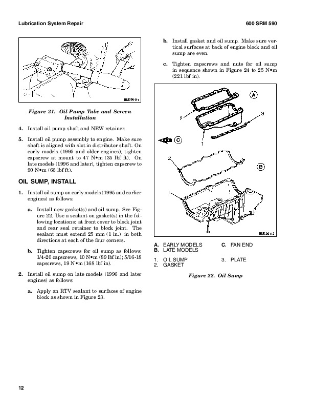
Install….57
Oil Pump….57
Remove….57
Inspect….57
Install….58
Relief Valve….58
Remove….58
Disassemble….58
Inspect….59
Assemble….59
Install….59
Fuel System Repair….59
Description….59
Fuel Filter, Replace….60
Fuel Injectors….60
Remove….60
Inspect….61
Install….61
Fuel Pump….62
Remove….62
Disassemble….62
Assemble….62
Install….63
Test….63
Water Separator….63
Remove….63
Disassemble….63
Assemble….64
Install….64
Fuel Injection Pump….64
Remove….64
Install….65
Fuel System Air Removal….66
Governor Weight Assembly….67
Remove….67
Install….67
Engine Speed Control Assembly….67
Remove….67
Replace….68
Install….68
Fuel Injection Pump Linkage….68
Remove….68
Fuel Control Lever, Replace….69
Governor Control Lever, Replace….69
Install….70
Record Maximum Fuel Position….71
Record Maximum Fuel Position of Fuel Rack….71
Set Adjustment Screw for Maximum Fuel Setting….72
Electrical Stop Solenoid….73
Remove….73
Install….74
Cooling System Repair….74
Description….74
Thermostat, Replace….74
Coolant Pump….74
Remove….74
Install….75
Fan….75
Remove….75
Install….75
Flywheel and Housing Repair….75
Description….75
Flywheel….75
Remove….75
Install….75
Ring Gear, Replace….76
Flywheel Housing….76
Remove….76
Install….76
Electrical System Repair….76
Drive Belt….76
Alternator….77
Remove….77
Install….77
Starter Motor….78
Remove….78
Install….78
Glow Plugs….78
Remove….78
Continuity Check….78
Operation Check….78
Install….79
Engine Specifications….79
Cylinder Head Assembly….79
Piston and Connecting Rods….81
Crankshaft Assembly….83
Crankshaft Heat Treatment….83
Crankshaft Overhaul….83
Timing Case and Gear Assembly….85
Engine Block Assembly….86
Timing Data….86
Lubrication System….86
Fuel System….87
Cooling System….87
Electrical Equipment….88
Torque Specifications….89
Cylinder Head Assembly….89
Piston and Connecting Rod Assemblies….89
Crankshaft Assembly….89
Timing Case and Drive Assembly….89
Lubrication System….89
Fuel System….89
Cooling System….90
Flywheel….90
Valve Cover….90
Electrical Equipment….90
Special Tools….91
tables….3
Table 1. Connecting Rod Dimensions….28
Table 2. Cylinder Head….79
Table 3. Valve Guides….80
Table 4. Inlet Valves….80
Table 5. Exhaust Valves….81
Table 6. Single Valve Springs….81
Table 7. Tappets….81
Table 8. Rocker Arm Shaft….81
Table 9. Rocker Arm….81
Table 10. Pistons….81
Table 11. Piston Rings….82
Table 12. Connecting Rods….82
Table 13. Piston Pins….82
Table 14. Connecting Rod Bearings….82
Table 15. Small End Bushings….83
Table 16. Crankshaft….83
Table 17. Crankshaft Overhaul Specifications….83
Table 18. Main Bearings….84
Table 19. Crankshaft Thrust Washers….85
Table 20. Camshaft….85
Table 21. Camshaft Thrust Washer….85
Table 22. Camshaft Gear….85
Table 23. Gear for Fuel Injection Pump….85
Table 24. Crankshaft Gear….85
Table 25. Idler Gear and Hub….85
Table 26. Engine Block….86
Table 27. Fuel Injection Pump….86
Table 28. Timing Data….86
Table 29. Fuel Injection Pump Timing Shims….86
Table 30. Oil Pump….86
Table 31. Relief Valve….86
Table 32. Oil Filter….87
Table 33. Fuel Injection Pump….87
Table 34. Fuel Pump….87
Table 35. Fuel Injector Codes….87
Table 36. Electrical Stop Solenoid….87
Table 37. Coolant Pump….87
Table 38. Thermostat….87
Table 39. Alternator….88
Table 40. Starter Motor….88
Table 41. Glow Plugs….88
hyster-1456991-12-03-srm0707….95
toc….95
Periodic Maintenance….95
Safety Precautions Maintenance and Repair….96
General….101
Serial Number….101
How to Move Disabled Lift Truck….101
How to Tow Lift Truck….101
How to Put Lift Truck on Blocks….102
How to Raise Drive Tires….102
How to Raise Steering Tires….102
Maintenance Schedule….103
Maintenance Procedures Every 8 Hours or Daily….121
How to Make Checks With Engine Stopped….121
Tires and Wheels….121
Forks….122
Adjust….123
Remove….123
Install….123
Forks, Mast, and Lift Chains, Inspect….123
Safety Labels….124
Operator Restraint System….125
Steering Column Latch….125
Fuel, Oil, or Coolant Leaks, Check….126
Drive Belt….126
Intake Manifold Rubber Cap….126
Powershift Transmission Oil Temperature….126
Powershift Transmission Oil Level….126
Engine Oil….126
Hydraulic System….128
Air Filter….128
How to Make Checks With Engine Running….128
Gauges, Indicator Lights, Horn, Fuses, and Relays….129
Check Engine Light (Mazda and GM LPG Closed Loop with Low-Emissi….130
Malfunction Indicator Lamp (GM 3.0L Gasoline Engine)….130
Engine Oil Pressure….130
Cooling System….131
Steering System….131
Service Brakes….131
Brake Fluid Level….131
Operation, Check….131
Parking Brake….131
Water Separator, Diesel Engine….132
Drain Water From Water Separator….132
Fuel Filter, Diesel Engine….132
Diesel Fuel System, Remove Air….132
Control Levers and Pedals….132
Lift System, Operate….132
Cooling System….133
Maintenance Procedures Every 250 Hours or 6 Weeks….133
Air Filter….133
Drive Belt….134
Mazda M4-2.0G and M4-2.2G Engines….134
Fan and Alternator Drive Belt….134
Timing Belt….134
GM 3.0L….134
Perkins 704-26 (UB)….135
Engine Oil and Filter….135
Brake Fluid….136
Hydraulic Tank Breather….136
Battery….136
Forks….136
Lift Chains….136
Lubrication….136
Wear, Check….136
Mast….137
Steering Axle….137
Fuel System….137
Engine Speed, Diesel, Perkins 704-26 (UB)….138
Engine Speed, LPG Carburetor, Mazda and GM (Aisan Open-Loop and ….138
Engine Speed, LPG Carburetor, Mazda (Impco)….138
Engine Speed, LPG Carburetor, GM 3.0L (Impco)….139
Engine Speed, Mazda Gasoline Carburetor….140
Hydraulic System….141
Cooling System, Clean Debris From Radiator Core….141
Maintenance Procedures Every 500 Hours or 3 Months….142
Drain Tar From Aisan LPG Regulator….142
PCV Valve….142
Maintenance Procedures Every 1000 Hours or 6 Months….142
Diesel Fuel System….142
Fuel Filter, Replace….142
Water Separator, Remove Water….143
Water Separator, Replace….143
Diesel Fuel System Air Removal….144
Differential and Drive Axle, Powershift Transmission….145
Valve Clearance, Check and Adjust….145
Ignition System….145
GM 3.0L LPG (IMPCO)….145
GM 3.0L LPG (Aisan)….145
Mazda M4-2.0G and M4-2.2G ….145
Aisan Regulator Pressure/Diaphragm and O-Ring Checks….146
PCV Valve….146
Integral Sideshift Carriage, Check Bearings….146
Control Levers and Pedals….146
Cooling System, GM 3.0L EPA Compliant Engine….147
LPG Fuel Filter (IMPCO), GM 3.0L EPA Compliant Engine, Replace….147
Inspect Engine Electrical System, Connectors, and FCVS Connectio….148
Maintenance Procedures Every 2000 Hours or Yearly….148
Hydraulic System….148
Hydraulic Oil and Filter, Replace….148
Powershift Transmission Oil and Filter….148
Replace….148
Cooling System….149
Service Brakes….149
Differential….150
LPG Fuel Filter Replace, (Pre-2004)….150
Gasoline Fuel Filter….150
Fuel Filter (Aisan LPG System), Replace….150
LPG Fuel Injector (Aisan Closed-Loop Low Emission System)….151
Integral Sideshift Carriage, Replace Bearings….151
Oxygen Sensor, GM 3.0L EPA Compliant Engine….151
Air Filter Element, GM 3.0L EPA Compliant Engine….151
Inspect Low Pressure Regulator (LPR) for Oil Buildup and Leaks….151
Check Throttle Shaft for Sticking….152
Inspect Exhaust Manifold and Piping for Leaks….152
Test LPG/GAS Regulator Pressure….153
Safety Procedures When Working Near Mast….153
Hood Latch Check….155
Lift Chain Adjustments….155
Lift and Tilt System Leak Check….157
Lift Cylinder, Leak Check….157
Tilt Cylinder, Leak Check….158
Charging Battery….158
Diesel Engine Fuel Injector Check….158
Welding Repairs….159
Overhead Guard Changes….159
Wheel and Tire Replacement….159
Solid Rubber Tire, Change S40-65XM Models….159
Remove and Install Tire on Wheel….160
Pneumatic Tire, Repair H45-65XM Models….161
Remove Wheels From Lift Truck….161
Remove Wheel From Tire….161
Remove Tire From Two-Piece Wheel….162
Remove Tire From Three- and Four-Piece Wheels….163
Install Wheel on Tire….164
Install Tire on Three- or Four-Piece Wheels….164
Install Three-Piece or Four-Piece Wheel in Tire….164
Install Tire on Two-Piece Wheel….165
Install Two-Piece Wheel in Tire….166
Add Air to Pneumatic Tires….166
Wheels, Install….167
Dual Drive Wheels, Install….167
Solid Rubber Tire, Change H45-65XM Models….167
Remove Wheel From Tire….168
Install Wheel in Tire….169
Adhesives and Sealants….171
tables….95
Table 1. Maintenance Schedule….104
Table 2. Hook-Type Carriage Chain Adjustment….156
Table 3. Pin-Type Carriage Chain Adjustment….156
hyster-1456997-01-03-srm0708….175
toc….175
Capacities and Specifications….175
Safety Precautions Maintenance and Repair….176
Lift Truck Weights….179
Tire Pressure….179
Capacities….180
Tire Sizes….181
Electrical System….181
Gasoline/LPG….181
Diesel….181
Transmission Oil Pressures….182
Hydraulic System….182
Stall Speeds….183
H2.00-3.20XM (H45-65XM)….183
S2.00-3.20XM (S40-65XM)….183
Engine Specifications….184
Gasoline/LPG….184
Diesel….185
Mast Speeds….186
H40-65XM Mast Speeds (US Models) – Mazda M4-2.0G Engine….186
H40-65XM Mast Speeds (US Models) – Mazda M4-2.2G Engine….187
H40-65XM Mast Speeds (US Models) – GM 3.0L Engine….188
H45-65XM Mast Speeds (US Models) – Perkins 704-26 (UB) Diesel En….190
S45-65XM Mast Speeds (US Models) – Mazda M4-2.0G Engine….191
S40-65XM Mast Speeds (US Models) – Mazda M4-2.2G Engine….193
S40-65XM Mast Speeds (US Models) – GM 3.0L Engine….194
H2.00-3.20XM Mast Speeds (European Models) – Mazda M4-2.0G Engin….198
H2.00-3.20XM Mast Speeds (European Models) – Mazda M4-2.2G Engin….199
H2.00-3.20XM Mast Speeds (European Models) – GM 3.0L Engine….200
H2.00-3.20XM Mast Speeds (European Models) – Perkins 704-26 (UB)….202
S2.00-3.20XM Mast Speeds (European Models) – Mazda M4-2.0G Engin….203
S2.00-3.20XM Mast Speeds (European Models) – Mazda M4-2.2G Engin….205
S2.00-3.20XM Mast Speeds (European Models) – GM 3.0L Engine….206
Torque Specifications….210
Frame….210
Brake System….210
Mast….210
Steering System….210
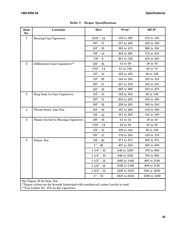
Drive Axle….210
Transmission and Differential….211
Engine – Mazda M4-2.0G and M4-2.2G….211
Engine – GM 3.0L….212
Engine – Perkins 704-26 (UB)….212
hyster-1456998-12-03-srm0709….217
toc….217
Diagrams….217
Safety Precautions Maintenance and Repair….218
hyster-1459370-11-03-srm0720….273
toc….273
Steering Housing and Control Unit….273
Safety Precautions Maintenance and Repair….274
General….277
Description….277
Operation….278
Steering Wheel and Column Assembly Repair….279
Assembly Components, Remove….279
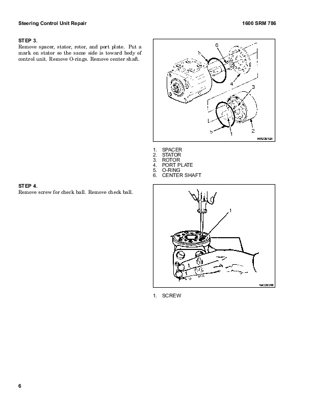
Steering Control Unit, Disassemble….281
Steering Control Unit, Clean….281
Steering Control Unit, Assemble….283
Assembly Components, Install….286
System Air Removal….288
Troubleshooting….288
Fuel Tank….470
Regulator….470
Start Mode….472
Idle Mode….472
Run Mode….472
Resonator….472
Carburetor….473
Start Mode….473
Idle Mode….473
Run Mode….473
Governor….474
Hoses Replacement….475
LPG Tank Repair….475
Remove….475
Install….476
Relief Valve Repair….476
Remove and Install….476
Carburetor Repair….476
Remove….476
Disassemble….476
Clean….477
Assemble….478
Install….478
Governor Repair….478
Remove….478
Inspect….478
Install….478
Regulator Repair….479
Remove….479
Disassemble….479
Clean….479
Inspect….479
Assemble….481
Install….482
Regulator Adjustment….482
Regulator Height Adjustment….482
Regulator Assembly Air Tightness Test….483
Carburetor Adjustment….484
Idle Speed and Fuel Mixture….484
Idle Control Adjustment….484
Governor Adjustment….485
Checks….485
Adjustments….485
Throttle Linkage Adjustment S/H2.00-3.20XM (S/H40-65XM)….486
MONOTROL® Pedal Check….487
Throttle Linkage Adjustment S/H1.50-2.00XMS (S/H25-40XMS)….488
Troubleshooting….489
tables….465
Table 1. Power Adjusting Screw….478
Table 2. Air Adjusting Screw….478
Table 3. Idle Mixture Adjusting Screw….481
Table 4. Idle Mixture Adjusting Screw….484
hyster-1495954-02-04-srm0948….497
toc….497
LPG Fuel System….497
Safety Precautions Maintenance and Repair….498
General….501
Description and Operation….502
Fuel Tank….502
Oxygen Sensor….503
Regulator….503
Start Mode….506
Idle Mode….506
Run Mode….506
Resonator….506
Carburetor….507
Start Mode….507
Idle Mode….508
Run Mode….508
Governor….508
Hoses Replacement….509
LPG Tank Repair….509
Remove….509
Install….510
Relief Valve Repair….510
Remove and Install….510
Carburetor Repair….510
Remove….510
Disassemble….510
Clean….511
Assemble….511
Install….512
Fuel Injector Repair….512
Remove….512
Clean and Inspect….512
Install….512
Governor Repair….513
Remove….513
Inspect….513
Install….513
Regulator Repair….513
Remove….513
Install….513
Oxygen Sensor Repair….514
Remove and Install….514
Vacuum Switches Repair….514
Remove and Install….514
Inspect….514
Resistor Repair….514
Remove and Install….514
Inspect….514
Carburetor and New Regulator Adjustment….514
Idle Speed and Fuel Mixture….514
Idle Control Adjustment….515
Governor Checks and Adjustments….516
Checks….516
Adjustments….516
Throttle Linkage Adjustment….517
MONOTROL Pedal Check….518
Check Engine Light….518
Inspect Warning Lamp….518
Check Feedback Operation….518
Check VAC1 and VAC2 Signals….518
Check Resistor….518
Check Fuel Injector….519
Check Oxygen Sensor….519
Check Vacuum Switch 1….519
Check Vacuum Switch 2….519
After Completing Checks….519
Troubleshooting….520
tables….497
Table 1. Adjusting Screw….512
hyster-1519772-07-02-srm1016….529
toc….529
Electronic Engine Control….529
Safety Precautions Maintenance and Repair….530
General….533
Description and Operation….533
General….533
Electronic Control Module (ECM)….533
Diagnostic Connector….533
How ECM Begins Operation….535
Electronic Engine Control….538
What ECM Does….538
Distributor….539
Ignition Module….540
When Engine Is Being Started….541
When Engine Is Running….542
Electronic Control Module (ECM) with Ignition Module Distributor….542
Fuel Control….543
Throttle Body Injection (TBI)….544
Fuel Injectors….544
Fuel Pressure Regulator….544
Throttle Position Sensor (TPS)….545
Idle Air Control (IAC)….545
GM 4.3L Engine Governor System….546
GM 3.0L Engine Governor System….546
Vacuum Ports….548
Fuel Pump….548
ECM Sensors and Controllers….550
Manifold Absolute Pressure (MAP)….550
Engine Coolant Temperature (ECT) Sensor….550
hyster-1519774-07-02-srm1017….553
toc….553
Electronic Engine Control….553
Safety Precautions Maintenance and Repair….554
General….561
Troubleshooting Procedure….561
How This Section Is Arranged….561
Where Do I Start?….561
Visual/Physical Inspection….561
Knowledge/Tools Required….561
Damage From Static Discharge (Static Electricity)….561
Troubleshooting Information….562
Malfunction Indicator Lamp (MIL)….562
Reading Diagnostic Trouble Codes (DTC)….562
Clearing Diagnostic Trouble Codes (DTCs)….566
ECM Diagnostic Codes Available….567
Diagnostic Mode….567
Field Service Mode….567
ECM Learning Ability….568
SCAN Tool Information….568
On-Board Diagnostic (OBD) System Check….570
Test Description….571
Troubleshooting Charts….572
General….572
Tools and Test Equipment….572
Presssure Conversion Chart….573
Troubleshooting Chart Description Summary….574
A-1 No Malfunction Indicator Lamp….575
Circuit Description….575
Diagnostic Aids….575
Test Description….575
A-2 No Scan Data, No DTC-12, Malfunction Indicator Lamp ON….577
Circuit Description….577
Diagnostic Aids….577
Test Description….577
A-3 Engine Cranks but Does Not Run….579
Circuit Description….579
Diagnostic Aids….579
Test Description….579
A-4 Fuel Injector Circuit….582
Circuit Description….582
Test Description….582
A-5 Fuel Pump Relay Circuit….584
Circuit Description….584
Diagnostic Aids….585
Test Description….585
A-6 Fuel System Troubleshooting….587
Circuit Description….587
Diagnostic Aids….587
Test Description….588
Test Description….590
A-7 Ignition System Troubleshooting….592
Circuit Description….592
Diagnostic Aids….593
Test Description….593
DTC 14 ECT Sensor Circuit – Low Temp Indicated (Scan Diagnostics….596
Circuit Description….596
Diagnostic Aids….597
Test Description….597
DTC 15 Engine Coolant Temperature (ECT) Sensor Circuit High Temp….598
Circuit Description….598
Diagnostic Aids….599
Test Description….599
DTC 21 Throttle Position (TP) Sensor Circuit Signal Voltage High….600
Circuit Description….600
Diagnostic Aids….601
Test Description….601
DTC 22 Throttle Position (TP) Sensor Circuit Signal Voltage Low….602
Circuit Description….602
Diagnostic Aids….603
Test Description….603
DTC 31 Engine Governor Circuit….604
Circuit Description….604
Diagnostic Aids….605
Test Description….605
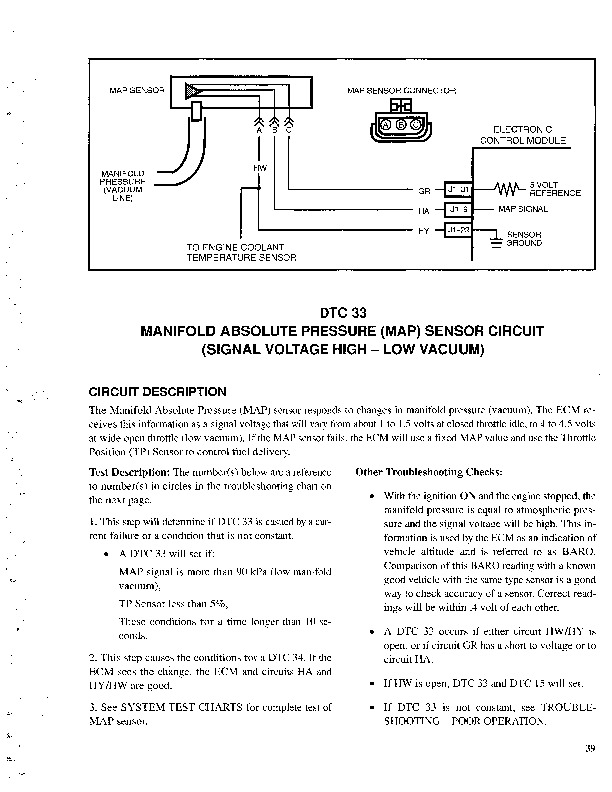
DTC 33 Manifold Absolute Pressure (MAP) Sensor Circuit Signal Vo….607
Circuit Description….607
Diagnostic Aids….607
Test Description….607
DTC 34 Manifold Absolute Pressure (MAP) Sensor Circuit Signal Vo….609
Circuit Description….609
Diagnostic Aids….610
Test Description….610
DTC 41 Electronic Spark Timing (EST) – Open EST Circuit….612
Circuit Description….612
Diagnostic Aids….612
Test Description….612
DTC 42 EST – Grounded EST Circuit, Open or Grounded Bypass Circu….614
Circuit Description….614
Diagnostic Aids….614
Test Description….614
DTC 51 Calibration Checksum Failure….616
Circuit Description….616
Diagnostic Aids….616
Test Description….616
DTC 81 Fuel Pump Relay Driver Circuit High, Low, or Open….617
Circuit Description….617
Diagnostic Aids….618
Test Description….618
DTC 81 5-Volt Reference Circuit Out of Range….620
Circuit Description….620
Diagnostic Aids….621
Test Description….621
DTC 81 FPRSENSE Circuit Fault….622
Circuit Description….622
Diagnostic Aids….623
Test Description….623
Troubleshooting, Poor Operation….624
General….624
Make a Careful Visual Check….624
FAULT: Codes or Performance That Is Abnormal….624
FAULT: Loss of Diagnostic Trouble Code (DTC) Memory….624
FAULT: Engine Quits While Driving….624
Additional Checks….624
FAULT: Engine Is Difficult to Start….624
FAULT: Variation in Engine Power When Throttle Is Held Steady….625
FAULT: Decreased Engine Power….625
FAULT: Detonation/Spark Knock….626
FAULT: Engine Momentarily Does Not Increase Power When Throttle ….626
FAULT: One or More Cylinders Do Not Operate Correctly – Engine D….627
FAULT: Rough Idle or Engine Stalls During Idle….627
FAULT: Fuel Usage Too High….627
FAULT: Dieseling….628
FAULT: Backfire….628
System Test Charts….628
General….628
Engine Coolant Temperature (ECT) Sensor Test….628
Throttle Position (TP) Sensor Check….629
Minimum Idle Speed….629
Adjustment….629
B-1 – Idle Air Control (IAC) System Check….631
Circuit Description….631
Diagnostic Aids….631
B-2 – Manifold Absolute Pressure (MAP) Sensor Output Test….632
Circuit Description….632
Test Description….633
B-3 – Check Governor System….635
Governor System Not Operating Correctly….635
Check Function of Governor System….635
Check PCV System….635
Fuel System Components Repair….636
General….636
Fuel Pressure Relief Procedure….636
Fuel Pump Replacement….636
Throttle Body Injection Unit (TBI)….637
Remove….637
Clean and Inspect….637
Install….638
Fuel Meter Body….640
Remove….640
Install….640
Fuel Injector….641
Remove….641
Install….641
Pressure Regulator….642
Remove….642
Inspect….642
Install….642
Throttle Position Sensor (TPS)….642
Remove….642
Install….643
Idle Air Control (IAC) Valve….643
Remove….643
Clean and Inspect….643
Install….643
Governor System 3.0L Engine Repair….644
Governor Module, Replace….644
Governor Motor, Replace….644
Throttle Cables, Install and Adjust….644
MONOTROL® Pedal, Check….645
Governor System 4.3L Engine Repair….646
Governor Throttle Drive Assembly….646
Remove….646
Inspect….647
Install….647
Governor Drive Motor….647
Remove….647
Clean and Lubricate….648
Install….648
Inspect….649
MONOTROL® Pedal, Check….649
Ignition System Components Repair….649
ECM Replacement….649
Function Check….650
Distributor….650
Remove….650
Disassemble….650
Inspect….651
Assemble….651
Install….651
Firing Order….651
Ignition Timing….652
Ignition Module Repair….652
Test For Fault….652
Replace….653
Sensing Coil….653
Test….653
Replace….653
Ignition Coil….653
Test….653
Remove….654
Install….654
Sensors Repair….654
Engine Coolant Temperature (ECT) Sensor, Replace….654
MAP Sensor, Replace….655
PCV System Repair….655
Replace….655
Wiring….655
Connectors and Terminals….656
Procedures for Spark Plugs, Spark Plug Wires, and Boots….658
Wiring Diagram….659
Spark Plugs Troubleshooting….663
Special Tools….664
tables….553
Table 1. ECM Diagnostic Codes Available….567
Table 2. Rinda SCAN Tool Information….568
Table 3. TECH 1 SCAN Tool Information….569
Table 4. On-Board Diagnostic System Checks….571
Table 5. Voltage and Pressure Chart….573
Table 6. Troubleshooting Chart Description Summary….574
Table 7. No Malfunction Indicator Lamp (GM 3.0L Engine Only)….576
Table 8. No Scan Data, No DTC-12, Malfunction Indicator Lamp ON….578
Table 9. Engine Cranks but Does Not Run….580
Table 10. Fuel Injector Circuit….582
Table 11. Fuel Pump Relay Circuit….585
Table 12. A-6A Fuel System Troubleshooting….588
Table 13. A-6B Fuel system Troubleshooting….591
Table 14. Ignition System Troubleshooting….593
Table 15. Engine Coolant Temperature Sensor….597
Table 16. DTC 14 Engine Coolant Temperature (ECT) Sensor Circuit….598
Table 17. Engine Coolant Temperature Sensor Table….599
Table 18. DTC 15 Engine Coolant Temperature (ECT) Sensor Circuit….600
Table 19. DTC 21 Throttle Position (TP) Sensor Circuit Signal Vo….601
Table 20. DTC 22 Throttle Position (TP) Sensor Circuit Signal Vo….603
Table 21. DTC 31 Engine Governor Circuit….605
Table 22. DTC 33 Manifold Absolute Pressure (MAP) Sensor Circuit….608
Table 23. DTC 34 Manifold Absolute Pressure (MAP) Sensor Circuit….610
Table 24. DTC 41 Electronic Spark Timing (EST) – Open EST Circui….613
Table 25. DTC 42 Electronic Spark Timing (EST) – Grounded EST Ci….615
Table 26. DTC 51 Calibration Checksum Failure….617
Table 27. DTC 81 Fuel Pump Relay Driver Circuit High, Low, or Op….618
Table 28. DTC 81 5 Volt Reference Circuit Out of Range….621
Table 29. DTC 81 FPRSENSE Circuit Fault….623
Table 30. ECT Sensor – Temperature vs. Resistance….629
Table 31. Idle Air Control (IAC) System Check….632
Table 32. Altitude Voltage Chart….633
Table 33. Manifold Absolute Pressure (MAP) Sensor Output Test….634
Table 34. ECM Connector J1 Identification….660
Table 35. ECM Connector J2 Identification….662
hyster-1558270-11-03-srm1020….669
toc….669
GM Engine Repair….669
Safety Precautions Maintenance and Repair….670
General….673
Description….673
Engine Removal and Installation….681
Cylinder Head and Valve Mechanism Repair….682
Cylinder Head, Remove….682
Cylinder Head, Disassemble….683
Clean and Inspect….684
Valves and Valve Seats….686
Studs for Rocker Arms….687
Hydraulic Valve Lifters….688
Replace….688
Clean and Inspect….688
Cylinder Head, Assemble….688
Cylinder Head, Install….688
Valve Clearance, Adjust….689
Rocker Arm Cover, Install….690
Timing Gear Cover Repair….690
Remove….690
Install….691
Camshaft Repair….692
Camshaft, Remove….692
Camshaft, Clean and Inspect….692
Camshaft Bearings, Remove….694
Camshaft Bearings, Clean and Inspect….695
Camshaft Bearings, Install….695
Camshaft, Install….695
Distributor Repair….696
Remove….696
Install….696
Lubrication System Repair….698
Oil Pan….698
Remove….698
Install….698
Oil Pump….698
Remove….698
Disassemble….699
Clean and Inspect….700
Assemble….700
Install….700
Piston and Piston Rod Assemblies Repair….700
Piston Rod Bearings, Replace….700
Piston and Piston Rod Assemblies, Remove….702
Piston and Piston Rod Assemblies, Disassemble….702
Pistons, Clean and Inspect….703
Cylinder Bores, Inspect and Repair….703
Piston Rings, Inspect….704
Piston and Piston Rod Assemblies, Assemble….705
Piston and Piston Rod Assemblies, Install….706
Crankshaft Repair….706
Main Bearings, Replace….706
Oil Seal for Rear Main Bearing, Replace….707
Crankshaft, Remove….708
Inspect and Repair….708
Main Bearing and Journal Clearance, Check….709
Crankshaft, Install….710
Flywheel and Flywheel Housing Repair….711
Flywheel, Remove….712
Ring Gear, Replace….712
Flywheel, Install….713
Cooling System Repair….713
Water Pump….713
Remove….713
Inspect….714
Install….714
Thermostat….714
Remove and Install….714
Alternator Repair….714
Starter Repair….714
Checks and Adjustments….716
Engine Compression Test….716
Test Procedure….716
Test Results….716
Engine Noise Diagnostic Test….716
Description….716
Test Procedure….716
Engine Specifications….718
Engine Data….718
Cylinder Bore….718
Piston….718
Piston Rings….718
Wrist Pin….719
Crankshaft….719
Piston Rod….720
Camshaft….720
Hydraulic Valve System….720
Cylinder Head Warpage….721
Lubrication System….721
Cooling System….721
Torque Specifications….722
Troubleshooting….723
hyster-1559540-03-04-srm1088….729
toc….729
Electronic Controlled LPG/Gasoline Fuel System….729
Safety Precautions Maintenance and Repair….730
General….735
Fuel System Warnings and Cautions….735
Glossary….736
Description and Operation of LPG Fuel System….740
Propane Fuel System….740
LPG Fuel Tank….740
Service Line….740
Fuel Filter….740
Low Pressure Lock-Off (LPL)….740
Low Pressure Regulator (LPR)….742
Air Fuel Mixer….743
Throttle Control Device….744
Drive By Cable….744
Three-Way Catalytic (TWC) Muffler….745
Electronic Control Module (ECM)….745
Heated Exhaust Gas Oxygen (HEGO) Sensor….747
Description and Operation of Gasoline Fuel System….747
Gasoline Fuel System Throttle Body Injection (TBI), 3.0L Engine ….747
Gasoline Multi-Point Fuel Injection (MPFI) System, 4.3L Only….747
Gasoline Fuel Storage Tank….749
Gasoline Fuel Pump….749
Fuel Filter….749
Fuel Pressure Regulator, 3.0L Only….749
Fuel Rail and Pressure Regulator, 4.3L Only….751
Fuel Injector….752
Throttle Control Device….752
Drive By Cable….752
Three-Way Catalytic Muffler….752
Electronic Control Module (ECM)….753
Heated Exhaust Gas Oxygen (HEGO) Sensor….755
LPG Fuel System Repair….755
Propane Fuel System Pressure Relief….755
Propane Fuel System Leak Test….755
Propane Fuel Filter Replacement….756
Remove….756
Install….756
Low Pressure Lock-Off (LPL) Replacement….756
Remove….756
Install….756
Pressure Trim Valve (PTV) Replacement….757
Remove….757
Install….758
Low Pressure Regulator….758
Remove….758
Install….758
Fuel Trim Valve (FTV) Solenoid Replacement….759
Remove….759
Install….760
Temperature Manifold Absolute Pressure (TMAP)….760
Remove….760
Install….760
Throttle Body Replacement….760
Remove….760
Install….761
Mixer Replacement….761
Remove….761
Install….761
Coolant Hose Replacement….761
Remove….761
Install….761
Vapor Hose Replacement….762
Remove….762
Install….762
Balance Line Hose Replacement….762
Remove….762
Install….762
PTV Hose Replacement….762
Remove….762
Install….762
FTV Hose Replacement….762
Remove….762
Install….763
Throttle Position Sensor (TPS) Replacement….763
Remove….763
Install….763
Foot Pedal Position (FPP) Sensor Replacement….763
Remove….763
Install….763
Electronic Control Module (ECM) Replacement….763
Remove….763
Install….764
Heated Exhaust Gas Oxygen (HEGO) Sensor Replacement….764
Remove….764
Install….764
Three-Way Catalytic Muffler (TWC) Replacement….764
Remove….764
Install….764
Restricted Exhaust System Diagnosis….764
Exhaust System Description….764
Tools Required….765
Diagnostic Tool….765
Check at Heated Exhaust Gas Oxygen Sensor (HEGO)….765
Gasoline Fuel System Repair….766
Gasoline MPFI and TBI Fuel System Pressure Relief….766
Gasoline Fuel System Leak Test….766
Throttle Body Injector (TBI) Assembly Replacement, 3.0L Only….766
Remove….766
Install….767
Throttle Body Assembly Replacement, 3.0L Only….767
Remove….767
Install….767
Throttle Body Assembly Replacement, 4.3L Only….768
Remove….768
Install….768
Fuel Rail Replacement, Gasoline 4.3L Only….769
Remove….769
Install….769
Injector Replacement, Gasoline 4.3L Only….769
Remove….769
Install….769
Injector Replacement, Gasoline 3.0L Only….771
Remove….771
Install….771
Temperature Manifold Absolute Pressure (TMAP) Replacement….771
Remove….771
Install….771
Throttle Position Sensor (TPS) Replacement….771
Remove….771
Install….771
Foot Pedal Position (FPP) Sensor Replacement….772
Remove….772
Install….772
Electronic Control Module (ECM) Replacement….772
Remove….772
Install….772
Heated Exhaust Gas Oxygen (HEGO) Sensor Replacement….772
Remove….772
Install….772
Three-Way Catalytic Muffler (TWC) Replacement….773
Remove….773
Install….773
Restricted Exhaust System Diagnosis….773
Exhaust System Description….773
Tools Required….773
Diagnostic Tool….773
Check at Heated Exhaust Gas Oxygen Sensor (HEGO)….773
LPG System Diagnosis….774
Fuel System Description….774
Diagnostic Aids….775
Tools Required….775
Duty Cycle Monitoring Tool….775
Diagnostic Tool….775
Pressure Gauges….775
Test Description….775
Gasoline System Diagnosis….782
Fuel System Description, 3.0L Only….782
Fuel System Description, 4.3L Only….783
Diagnostic Aids….783
Tools Required….784
Diagnostic Tool….784
Test Description….784
LPG Symptom Diagnosis….791
Gasoline Symptom Diagnosis….804
Wire Harness Repair….814
On Vehicle Service Wiring Harness Repair….814
Connectors and Terminals….815
Twisted/Shielded Cable Repair….815
Twisted Leads Repair….816
Micro-Pack….817
Metri-Pack….817
Remove….817
Weather-Pack….819
Table 18. No Start….806
Table 19. Hard Start….807
Table 20. Cuts Out or Misses….808
Table 21. Hesitation, Sag, or Stumble….809
Table 22. Backfire….810
Table 23. Lack of Power, Sluggishness, or Sponginess….811
Table 24. Poor Fuel Economy….812
Table 25. Rough, Unstable, Incorrect Idle, or Stalling….813
Table 26. Surges or Chuggles….814
hyster-1559545-01-04-srm1090….825
toc….825
Electronic Control Module (ECM) Diagnostic Troubleshooting….825
Safety Precautions Maintenance and Repair….826
General….833
Description of ECM Based Diagnostics….833
Definition of Terms….833
Diagnostics Overview of the Spectrum Fuel System….833
Malfunction Indicator Lamp (MIL)….834
Spectrum Diagnostic Trouble Codes (DTC)….834
Using a Laptop Computer to Diagnose the Spectrum System….834
Installing the Spectrum Diagnostic Software….834
Connecting a Laptop Computer to the Spectrum System….835
Diagnostic Trouble Codes….835
Checking Diagnostic Trouble Codes….835
Clearing Diagnostic Trouble Codes….836
DATA Stream….836
Reading Sensor and Actuator Values….836
Graphing and Data Logging….837
Ignition System Test….838
Disabling Ignition Outputs….838
Injector Test….839
Disabling Injectors….839
Throttle Test….840
Using a Diagnostic Jumper to Diagnose the ECI System….840
On-Board Diagnostics System Check/Malfunction indicator lamp….841
Circuit Description….841
Preliminary and Intermittent Checks….844
DTC 111 – IAT High Voltage Bosch® TMAP….846
Circuit Description….846
Conditions for Setting the DTC….846
DTC 111 – IAT High Voltage Motorola® TMAP….849
Circuit Description….849
Conditions for Setting the DTC….849
DTC 112 – IAT Low Voltage Bosch® TMap….852
Circuit Description….852
Conditions for Setting the DTC….852
DTC 112 – IAT Low Voltage Motorola® TMAP….854
Circuit Description….854
Conditions for Setting the DTC….854
DTC 113 – IAT Higher Than Expected 1 Bosch® TMAP….857
Circuit Description….857
Conditions for Setting the DTC….857
Diagnostic Aids….857
DTC 113 – IAT Higher Than Expected 1 Motorola® TMAP….858
Circuit Description….858
Conditions for Setting the DTC….858
Diagnostic Aids….858
DTC 114 – IAT Higher Than Expected 2 Bosch® TMAP….859
Circuit Description….859
Conditions for Setting the DTC….859
Diagnostic Aids….859
DTC 114 – IAT Higher Than Expected 2 Motorola® TMAP….860
Circuit Description….860
Conditions for Setting the DTC….860
Diagnostic Aids….860
DTC 115 – Oil Pressure Low….861
Circuit Description….861
Conditions for Setting the DTC….861
DTC 121 – ECT Voltage High….864
Circuit Description….864
Conditions for Setting the DTC….865
DTC 122 – ECT Low Voltage….868
Circuit Description….868
Conditions for Setting the DTC….868
DTC 123 – ECT Higher Than Expected 1….870
Circuit Description….870
Conditions for Setting the DTC….870
DTC 124 – ECT Higher Than Expected 2….872
Circuit Description….872
Conditions for Setting the DTC….872
DTC 131 – MAP High Pressure Bosch® TMAP….873
Circuit Description….873
Conditions for Setting the DTC….873
Diagnostic Aids….874
DTC 131 – MAP High Pressure Motorola® TMAP….876
Circuit Description….876
Conditions for Setting the DTC….876
Diagnostic Aids….877
DTC 132 – MAP Low Voltage Bosch® TMAP….880
Circuit Description….880
Conditions for Setting the DTC….880
DTC 132 – MAP Low Voltage Motorola® TMAP….884
Circuit Description….884
Conditions for Setting the DTC….884
DTC 134 – BP High Pressure Bosch® TMAP….888
Circuit Description….888
Conditions for Setting the DTC….888
DTC 134 – BP High Pressure Motorola® TMAP….890
Circuit Description….890
Conditions for Setting the DTC….890
DTC 135 – BP Low Pressure Bosch® TMAP….892
Circuit Description….892
Conditions for Setting the DTC….892
DTC 135 – BP Low Pressure Motorola® TMAP….896
Circuit Description….896
Conditions for Setting the DTC….896
DTC 142 – Crank Sync Noise….900
Circuit Description….900
Conditions for setting the DTC….900
DTC 143 – Never Crank Synced At Start….903
Circuit Description….903
Conditions for Setting the DTC….903
DTC 144 – Camshaft Sensor Loss….906
Circuit Description….906
Conditions for Setting the DTC….906
DTC 145 – Camshaft Sensor Noise….909
Circuit Description….909
Conditions for Setting the DTC….909
DTC 211 – Closed Loop Multiplier High (LPG)….912
Circuit Description….912
Conditions for Setting the DTC….912
Diagnostic Aids….913
DTC 212 – HO 2 S Open/Inactive….914
Circuit Description….914
Conditions for Setting the DTC….914
DTC 213 – HO 2 S Open/Inactive (Post-Cat)….918
Circuit Description….918
Conditions for Setting the DTC….918
DTC 221 – Closed Loop Multiplier High (Gasoline)….920
Circuit Description….920
Conditions for Setting the DTC….920
Diagnostic Aids….920
DTC 222 – Closed Loop Multiplier Low (Gasoline)….923
Circuit Description….923
Conditions for Setting the DTC….923
Diagnostic Aids….924
DTC 224 – Closed Loop Multiplier Low (LPG)….925
Circuit Description….925
Conditions for Setting the DTC….925
Diagnostic Aids….926
DTC 241 – Adaptive Lean Fault (High Limit-Gasoline)….927
Circuit Description….927
Conditions for Setting the DTC….927
Diagnostic Aids….928
DTC 242 – Adaptive Rich Fault (Low Limit-Gasoline)….930
Circuit Description….930
Conditions for Setting the DTC….930
Diagnostic Aids….930
DTC 243 – Adaptive Learn High (LPG)….932
Circuit Description….932
Conditions for Setting the DTC….932
Diagnostic Aids….933
DTC 244 – Adaptive Learn Low (LPG)….936
Circuit Description….936
Conditions for Setting the DTC….936
Diagnostic Aids….937
DTC 261 – System Voltage Low….939
Circuit Description….939
Conditions for Setting the DTC….939
DTC 262 – System Voltage High….942
Circuit Description….942
Conditions for Setting the DTC….942
DTC 411 – Injector Driver 1 Open (3.0L only)….944
Circuit Description….944
Conditions for Setting the DTC….944
DTC 412 – Injector Driver 1 Shorted (3.0L only)….947
Circuit Description….947
Conditions for Setting the DTC….947
DTC 511 – COP Failure….950
Circuit Description….950
Conditions for Setting the DTC….950
DTC 512 – Invalid Interrupt….952
Circuit Description….952
Conditions for Setting the DTC….952
DTC 513 – A/D Loss….954
Circuit Description….954
Conditions for Setting the DTC….954
DTC 514 – RTI 1 Loss….956
Circuit Description….956
Conditions for Setting the DTC….956
DTC 515 – Flash Checksum Invalid….958
Circuit Description….958
Conditions for Setting the DTC….958
DTC 516 – Ram Failure….960
Circuit Description….960
Conditions for Setting the DTC….960
DTC 531 – External 5V Ref Lower Than Expected….962
Circuit Description….962
Conditions for Setting the DTC….962
DTC 532 – External 5V Ref Higher Than Expected….964
Circuit Description….964
Conditions for Setting the DTC….964
DTC 555 – RTI 2 Loss….966
Circuit Description….966
Conditions for Setting the DTC….966
DTC 556 – RTI 3 Loss….968
Circuit Description….968
Conditions for Setting the DTC….968
DTC 611 – FPP High Voltage….970
Circuit Description….970
Conditions for Setting the DTC….970
DTC 612 – FPP Low Voltage….974
Circuit Description….974
Conditions for Setting the DTC….974
DTC 631 – TPS1 Signal Voltage High….978
Circuit Description….978
Conditions for Setting the DTC….978
DTC 632 – TPS1 Signal Voltage Low….981
Circuit Description….981
Conditions for Setting the DTC….981
DTC 637 – Throttle Unable To Open….984
Circuit Description….984
Conditions for Setting the DTC….984
DTC 638 – Throttle Unable To Close….986
Circuit Description….986
Conditions for Setting the DTC….986
DTC 651 – Maximum Govern Speed Override….990
Circuit Description….990
Conditions for Setting the DTC….990
DTC 652 – Fuel Rev Limit….992
Circuit Description….992
Conditions for Setting the DTC….992
DTC 653 – Spark Rev Limit….995
Circuit Description….995
Conditions for Setting the DTC….995
Wire Harness Repair….997
On Vehicle Service Wiring Harness Repair….997
Connectors and Terminals….998
Twisted/Shielded Cable Repair….998
Twisted Leads Repair….999
Micro-Pack….1000
Metri-Pack….1000
Remove….1000
Weather-Pack….1002
Weather-Pack Terminal Repair….1002
tables….825
Table 1. OBD System Check….842
Table 2. Preliminary Checks….844
Table 3. Intermittent Checks….845
Table 4. DTC 111 – IAT Voltage High (Bosch® TMAP)….847
Table 5. DTC 111 – IAT Voltage High (Motorola® TMAP)….850
Table 6. DTC 112 – IAT Low Voltage (Bosch® TMAP)….853
Table 7. DTC 112 – IAT Low Voltage (Motorola® TMAP)….855
Table 8. DTC 115 – Oil Pressure Low….862
Table 9. Temperature Resistance….864
Table 10. DTC 121 – ECT VOLTAGE HIGH….865
Table 11. DTC 122 – ECT Low Voltage….869
Table 12. DTC 123 – ECT Higher Than Expected 1….871
Table 13. DTC 124 – ECT Higher Than Expected 2….873
Table 14. DTC 131 – MAP HIGH PRESSURE (Bosch® TMAP)….874
Table 15. DTC 131 – MAP HIGH PRESSURE (Motorola® TMAP)….877
Table 16. DTC 132 – MAP Low Voltage (Bosch® TMAP)….881
Table 17. DTC 132 – MAP Low Voltage (Motorola® TMAP)….885
Table 18. DTC 134 – BP High Pressure (Bosch® TMAP)….889
Table 19. DTC 134 – BP High Pressure (Motorola® TMAP)….891
Table 20. DTC 135 – BP Low Pressure (Bosch® TMAP)….893
Table 21. DTC 135 – BP Low Pressure (Motorola® TMAP)….897
Table 22. DTC 142 – Crank Sync Noise….901
Table 23. DTC 143 – Never Crank Synced At Start….903
Table 24. DTC 144 – Camshaft Sensor Loss….906
Table 25. DTC 145 – Camshaft Sensor Noise….910
Table 26. DTC 211 – Closed Loop Multiplier High (LPG)….913
Table 27. DTC 212 – HO 2 S Open/Inactive….915
Table 28. DTC 213 – HO 2 S Open/Inactive (Post-Cat)….919
Table 29. DTC 221 – Closed Loop Multiplier High (Gasoline)….921
Table 30. DTC 222 – Closed Loop Multiplier Low (Gasoline)….924
Table 31. DTC 224 – Closed Loop Multiplier Low (LPG)….926
Table 32. DTC 241 – Adaptive Lean Fault (High Limit-Gasoline)….928
Table 33. DTC 242 – Adaptive Rich Fault (Low Limit-Gasoline)….931
Table 34. DTC 243 – Adaptive Learn High (LPG)….934
Table 35. DTC 244 – Adaptive Learn Low (LPG)….937
Table 36. DTC 261 – System Voltage Low….940
Table 37. DTC 262 – System Voltage High….943
Table 38. DTC 411 – Injector Driver 1 Open (3.0L Only)….945
Table 39. DTC 412 – Injector Driver 1 Shorted (3.0L only)….948
Table 40. DTC 511 – COP Failure….951
Table 41. DTC 512 – Invalid Interrupt….953
Table 42. DTC 513 – A/D Loss….955
Table 43. DTC 514 – RTI 1 Loss….957
Table 44. DTC 515 – Flash Checksum Invalid….959
Table 45. DTC 516 – Ram Failure….961
Table 46. DTC 531 – External 5V Ref Lower Than Expected….963
Table 47. DTC 532 – External 5 V Ref Higher Than Expected….965
Table 48. DTC 555 – RTI 2 Loss….967
Table 49. DTC 556 – RTI 3 Loss….969
Table 50. DTC 611 – FPP High Voltage….971
Table 51. DTC 612 – FPP Low Voltage….975
Table 52. DTC 631 – TPS1 Signal Voltage High….979
Table 53. DTC 632 – TPS1 Signal Voltage Low….982
Table 54. DTC 637 – Throttle Unable To Open….985
Table 55. DTC 638 – Throttle Unable To Close….987
Table 56. DTC 651 – Maximum Govern Speed Override….991
Table 57. DTC 652 – Fuel Rev Limit….993
Table 58. DTC 653 – Spark Rev Limit….996
hyster-897097-03-03-srm0316….1007
toc….1007
Steering Axle….1007
Safety Precautions Maintenance and Repair….1008
General….1011
Description….1011
Steering Axle Assembly Repair….1012
Remove….1012
Install….1012
Wheels and Hubs Repair….1013
Remove and Disassemble….1013
Clean….1013
Assemble and Install….1013
Spindles, Bearings, and Tie Rods Repair….1015
Remove….1015
Install….1015
Steering Cylinder Repair….1016
Remove and Disassemble….1016
Clean and Inspect….1017
Assemble and Install….1017
Torque Specifications….1017
Troubleshooting….1018
hyster-897477-02-01-srm0496….1023
toc….1023
Mazda Engine….1023
Safety Precautions Maintenance and Repair….1024
General….1027
Description….1027
Engine Removal and Installation….1027
Cylinder Head, Camshaft, and Valve Mechanism Repair….1028
Remove….1028
Clean….1029
Inspect and Repair….1030
Cylinder Head….1030
Rocker Shaft Assembly….1030
Camshaft….1030
Valve Guides….1031
Valve Seats….1032
Valves….1032
Valve Springs….1033
Install….1033
Crankshaft and Main Bearings Repair….1036
Remove….1036
Inspect and Repair….1036
Crankshaft….1036
Main Bearings….1036
Install….1037
Pistons and Connecting Rods Repair….1038
Remove and Disassemble….1038
Clean….1038
Inspect and Repair….1038
Pistons….1038
Piston Rings….1038
Connecting Rods and Bearings….1039
Assemble and Install….1039
Cylinder Block Repair….1041
Oil Pump Repair….1041
Remove….1041
Disassemble….1042
Clean….1042
Inspect….1043
Assemble….1043
Install….1044
Cooling System Repair….1044
Thermostat….1044
Replace….1044
Fan Assembly….1044
Remove and Disassemble….1044
Assemble and Install….1045
Water Pump….1045
Remove and Disassemble….1045
Assemble and Install….1046
Distributor Repair….1047
Remove….1047
Install….1047
Flywheel and Ring Gear Repair S/H2.00-3.20XM (S/H40-65XM)….1048
Remove….1048
Ring Gear, Replace….1048
Install….1048
Flywheel Repair H1.50-175XM, H2.00XMS (S/H25-35XM, S/H40XMS)….1049
Remove….1049
Install….1049
Valve Adjustment….1050
Compression Pressure Check….1051
Engine Timing Adjustment….1051
Throttle Linkage Adjustment….1052
Gasoline Engines….1052
LPG Engines (IMPCO)….1052
LPG Engines (AISAN)….1052
Engine Specifications….1052
Engine Data….1052
Thermostat….1052
Cylinder Head….1052
Valve Mechanism….1053
Camshaft….1053
Crankshaft….1053
Connecting Rods….1054
Cylinder Block….1054
Pistons….1054
Oil Pump….1054
Torque Specifications….1055
Troubleshooting….1056
Single-Speed Powershift Transmission….1097
Safety Precautions Maintenance and Repair….1098
General….1101
Description and Operation….1101
General….1101
Torque Converter….1102
Description….1102
Operation….1102
Clutch Assemblies….1104
Description….1104
Operation….1105
Hydraulic System….1108
General….1108
Control Valve….1109
General….1109
Clutch Pressure Regulator….1110
Inching Spool Assembly….1111
Direction Spool….1111
Modulator Circuit….1111
Torque Converter Regulator….1111
MONOTROL® Pedal….1111
MONOTROL Pedal Start Circuit….1112
Direction Control Lever….1112
Differential….1112
Oil Flow Diagrams….1114
Neutral….1114
Modulator Operation….1114
Forward….1118
Forward-Inching….1118
hyster-897482-08-03-srm0501….1125
toc….1125
Single-Speed Powershift Transmission….1125
Safety Precautions Maintenance and Repair….1126
General….1129
Transmission Removal….1131
Torque Converter and Housing Repair….1133
Remove….1133
Install….1133
Transmission Pump Repair….1135
Remove….1135
Repair….1135
Install….1135
Front Cover and Pump Drive Repair….1135
Remove and Disassemble….1135
Assemble and Install….1135
Clutch Assemblies Repair….1138
Remove and Disassemble….1141
Inspect….1142
Assemble….1143
Install….1148
Differential Repair….1149
Remove and Disassemble….1149
Inspect….1150
Assemble and Install….1151
Control Valve Repair….1158
Remove and Disassemble….1158
Inspect….1161
Assemble and Install….1161
MONOTROL® Pedal Repair….1162
Remove and Disassemble….1162
Assemble and Install….1162
Direction Control Lever Repair….1166
Remove and Disassemble….1166
Assemble and Install….1166
Stall Test….1167
Inching/Brake Pedal Adjustment….1168
Neutral Start Switch, MONOTROL Pedal Adjustment H2.00-3.20XM (H4….1172
Neutral Start Switch, MONOTROL Pedal Adjustment S2.00-3.20XM (S4….1173
Neutral Start Switch Test, MONOTROL® Pedal….1174
Oil Pressure Checks….1174
Relief Valve for Transmission Pump Check, TEST PORT 1….1174
Clutch Pressure Check, TEST PORTS 2 and 3….1174
Torque Converter Regulator Check, TEST PORT 4….1175
Lubrication Circuit Oil Pressure Check, TEST PORT 5….1175
Modulator Pressure Check, TEST PORT 6….1176
Troubleshooting….1176
Troubleshooting – Pressure Tests….1179
tables….1125
Table 1. Adjustment of Shims for Pinion Assembly….1152
Table 2. Ring and Pinion Tooth Contact Adjustment….1153
Table 3. Stall Speeds….1168
Table 4. Transmission Oil Pressures Test Ports….1175
Overhead Guard Repair….1214
Remove and Install….1214
Counterweight Repair….1215
Remove….1215
Install….1216
Exhaust System Repair….1218
Muffler, Replace….1218
Radiator and Cooling System Repair….1223
Remove….1223
Install….1223
Operator Restraint System Repair….1225
Engine Repair….1226
Remove Engine Only….1226
Remove Engine and Transmission….1226
Install Engine Only….1227
Install Engine and Transmission….1228
Fuel and Hydraulic Tanks Repair….1228
Inspect….1228
Small Leaks, Repair….1228
Large Leaks, Repair….1228
Clean….1229
Steam Method of Cleaning….1229
Chemical Solution Method of Cleaning….1229
Additional Preparations for Repair….1229
Safety Labels….1230
tables….1207
Table 1. Weight of Counterweights….1216
Brake System….1235
Safety Precautions Maintenance and Repair….1236
General….1239
Description and Operation….1239
Service Brakes….1239
Master Cylinder….1240
Parking Brake….1241
Service Brakes Repair….1241
Remove and Disassemble….1241
Clean….1243
Inspect….1243
Assemble and Install….1245
Adjust….1247
Parking Brake Repair….1248
Remove and Disassemble….1248
Assemble and Install….1248
Adjust….1248
Master Cylinder Repair….1249
Remove….1249
Clean and Inspect….1250
Repair….1250
Install….1253
Service Brakes Adjustment….1253
Brake System Air Removal….1254
Parking Brake Not Applied Switch Test….1254
Parking Brake Switch Test (MONOTROL® Pedal Only)….1254
Inching/Brake Pedal Adjustment….1255
Neutral Start Switch Adjustment, MONOTROL Pedal H2.00-3.20XM (H4….1257
Neutral Start Switch Adjustment, MONOTROL Pedal S2.00-3.20XM (S4….1258
Neutral Start Switch Test (MONOTROL Pedal)….1259
Torque Specifications….1260
H2.00-3.20XM (H40-65XM)….1260
S2.00-3.20XM (S40-65XM)….1260
Troubleshooting….1260
Instrument Cluster….1279
Safety Precautions Maintenance and Repair….1280
General….1283
Description….1283
Display Panels on Steering Column, Internal Combustion….1283
Display Panels on Steering Column, Electric Lift Trucks….1288
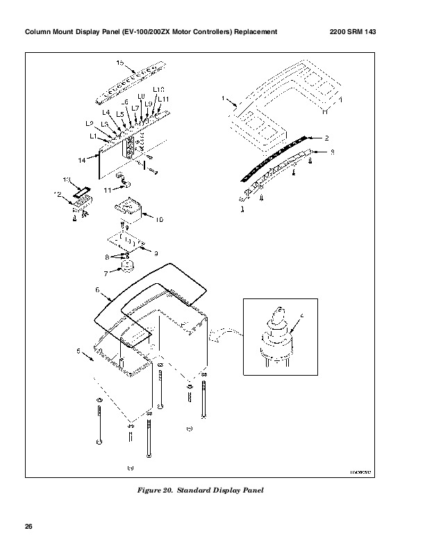
Standard Display Panel….1288
Enhanced Display Panel….1289
Curtis 1215 Display Panel….1293
Description and Features….1293
Operation….1293
Cluster-Type Display Panel (Internal Combustion) Replacement….1294
Remove and Disassemble….1294
Assemble and Install….1297
Cluster Display Panel (Electric Lift Truck) Replacement….1299
Display Panel Assembly, Replace….1299
LED Indicators….1299
Battery Indicators….1300
Digital Display (Enhanced Display Panel Only)….1300
Status Code or Performance Level Switches and LED indicators (En….1300
Standard Display Panel Parts, Replace….1300
Enhanced Display Panel Parts, Replace….1301
Curtis 1215 Display Panel Replacement….1301
Remove….1301
Install….1301
tables….1279
Table 1. Instrument Cluster, Internal Combustion….1283
Mast….1321
Safety Precautions Maintenance and Repair….1322
General….1325
Description and Operation….1325
Carriages….1325
Mast Mounts….1327
Two-Stage Mast, Limited Free-Lift (LFL)….1328
Description and Operation….1328
Two-Stage Mast, Full Free-Lift (FFL)….1330
Description and Operation….1330
Three-Stage Mast, Full Free-Lift (FFL)….1332
Description and Operation….1332
Cylinder Cushion During Lifting Sequence….1335
Cylinder Cushion During Lowering Sequence….1336
hyster-897507-11-03-srm0522….1339
toc….1339
Mast….1339
Safety Precautions Maintenance and Repair….1340
General….1343
Safety Procedures When Working Near Mast….1343
Forks Repair….1345
Remove….1345
Install….1345
Carriages Repair….1346
Standard Carriage, Remove….1346
Hang-On Sideshift Carriage, Remove….1347
Standard Carriage and Hang-On Sideshift Carriage, Repair….1348
Standard Carriage, Install….1348
Hang-On Sideshift Carriage, Install….1349
Integral Sideshift Carriage….1349
Remove….1349
Clean and Inspect….1351
Repair….1351
Install….1352
Mast Repair….1352
Remove….1352
Two-Stage LFL and Two-Stage FFL Masts, Disassemble….1354
Three-Stage FFL Mast….1361
Disassemble….1361
Mast and Chains, Clean and Inspect….1365
Two-Stage LFL and Two-Stage FFL Mast, Assemble….1366
Three-Stage FFL Mast, Assemble….1367
Install….1368
Lift Cylinders Repair….1369
Main Lift Cylinders, Remove….1369
Free-Lift Cylinder, Remove….1370
Lift Cylinders, Disassemble….1370
Lift Cylinders, Assemble….1373
Main Lift Cylinders, Install….1374
Free-Lift Cylinder, Install….1374
Header Hose Arrangements….1375
Two-Stage LFL Mast, New Hose Install….1375
Two-Stage LFL Mast, Adjust Hoses After Installation….1380
Two-Stage FFL Mast, New Hose Install….1381
Two-Stage FFL Mast, Adjust Hoses After Installation….1387
Three-Stage FFL Mast, New Hose Install….1387
Three-Stage FFL Mast, Adjust Hoses After Installation….1398
Header Hose Arrangement….1399
Two-Stage LFL Mast, New Hose Install….1399
Two-Stage LFL Mast, Adjust Hoses After Installation….1403
Two-Stage FFL Mast, New Hose Install….1403
Two-Stage FFL Mast, Adjust Hoses After Installation….1408
Three-Stage FFL Mast, New Hose Install….1410
Three-Stage FFL Mast, Adjust Hoses After Install….1418
Lift and Tilt System Leak Check….1419
Lift Cylinders Leak Check….1419
Tilt Cylinders Leak Check….1419
Tilt Cylinders Adjustment….1420
Lift Chains Adjustment….1421
Mast Adjustment….1423
Carriage Adjustment….1425
Troubleshooting….1425
tables….1339
Table 1. Hook-Type Carriage Chain Adjustment….1422
Table 2. Pin-Type Carriage Chain Adjustment….1422
hyster-897508-01-96-srm0523….142
Electrical System….1457
Safety Precautions Maintenance and Repair….1458
General….1461
Description….1461
Starting System….1461
Ignition System….1461
Charging System….1462
Starter Repair….1463
Remove and Disassemble….1463
Assemble and Install….1463
Coil Replacement….1465
Distributor Repair H1.50-1.75XM, H2.00XMS (S/H25-35XM, S/H40XMS)….1466
Remove and Disassemble….1466
Assemble and Install….1466
Distributor Repair S/H2.00-3.20XM (S/H40-65XM)….1468
Remove and Disassemble….1468
Assemble and Install….1470
Alternator Repair….1470
Remove and Disassemble….1470
Assemble and Install….1472
General Checks and Adjustments….1472
Starter Checks….1472
Operation, Check….1472
Brush Holder, Check….1473
Armature, Check….1473
Field Windings, Check….1473
Clutch and Bearing, Check….1474
Ignition System Check and Adjustment….1474
Engine Timing, Adjust….1474
Spark Plugs, Check….1475
Charging Circuit Checks….1475
Low Output, Check….1475
High Output, Check….1476
Diodes, Check….1476
Rotor Field Winding, Check….1477
Stator Windings, Check….1477
Brushes and Bearings, Check….1478
Voltage Regulator, Check….1478
Troubleshooting….1478
Radiator Cap….1640
Thermostat….1640
Water Pump….1641
Fan and Fan Shroud….1641
Cooling System Checks….1641
Radiator….1641
Thermostat….1641
Water Pump….1642
Exhaust Leaks….1642
Fan and Fan Shroud….1642
Radiator Cleaning….1642
Drain….1642
Clean….1642
Fill….1643
Troubleshooting….1644
hyster-899784-10-03-srm0002….1647
toc….1647
Alternator with Regulator….1647
Safety Precautions Maintenance and Repair….1648
General….1651
Description….1651
Alternator Repair….1653
Alternator Type A….1653
Remove and Disassemble….1653
Clean….1654
Assemble….1655
Install….1655
Alternator Type B….1658
Remove and Disassemble….1658
Clean….1658
Assemble….1659
Install….1660
General Check and Adjustment….1661
Low Output Check (Type A or Type B)….1661
High Output Check (Type A or Type B)….1663
Brushes Circuit Check….1664
Delco Alternators….1664
Motorola Alternators….1665
Diodes Check….1666
Diode Bridge Check….1666
Delco and Leece-Neville Alternators….1666
Motorola Alternators….1666
Rotor Field Winding Check….1667
Stator Windings Check….1668
Voltage Regulator Check….1668
Troubleshooting….1668
hyster-899788-03-02-srm0107….1673
toc….1673
High Energy Ignition (HEI) System….1673
Safety Precautions Maintenance and Repair….1674
Description….1677
Distributor Repair….1679
Remove….1679
Disassemble….1679
Assemble….1684
Install, If Crankshaft WAS NOT Rotated when Distributor was Remo….1685
Install, If Crankshaft WAS Rotated when Distributor was Removed….1685
Ignition Coil Replacement….1686
Some Four- and Six-Cylinder Models….1686
Remove….1686
Install….1687
V8, Some Four- and Six-Cylinder Models….1687
Remove….1687
Install….1688
Electronic Module Replacement….1689
Remove….1689
Install….1689
Sensing Coil Replacement….1690
Remove….1690
Install….1690
Spark Plugs Replacement….1690
Remove….1690
Install….1691
Visual Check….1691
High Voltage Wires Check….1691
Ignition Coil Check….1692
Coil in Distributor Cap Design….1692
Separate Coil Design….1692
Sensing Coil, Check….1693
Electronic Module Check….1693
Ignition Timing Adjustment….1693
GM V8-366 (6-liter) Ignition System Check….1695
GM V6-LPG (4.3 liter) GM V6-LPG (4.3 liter) Ignition Timing and ….1695
Specifications….1695
Troubleshooting….1696
hyster-910102-10-03-srm0103….1701
toc….1701
Tilt Cylinders….1701
Safety Precautions Maintenance and Repair….1702
General….1705
Description….1705
Tilt Cylinder Repair….1705
Remove….1705
Disassemble….1705
Clean….1705
Assemble….1706
Tilt Cylinders With O-Ring or Single-Lip Seals….1706
Tilt Cylinders for XM and XMS Models….1707
Tilt Cylinders for H700-800A and Early Model H700-920B….1708
Install….1709
Tilt Cylinders Using Chevron Packing….1710
Install….1711
Tilt Cylinder Leak Check….1713
Tilt Cylinder Stroke and Mast Tilt Angle Adjustment….1714
Torque Specifications….1715
Piston Rod Nut….1715
Retainer….1716
Troubleshooting….1718
tables….1701
Table 1. Movement Rates (Maximum) for Tilt Cylinders….1714
hyster-910107-02-01-srm0106….1721
toc….1721
Starter….1721
Safety Precautions Maintenance and Repair….1722
General….1725
Description and Operation….1725
Starter Repair….1727
Remove….1727
Disassemble….1727
Clean….1728
Assemble….1728
Install….1729
General Checks and Adjustments….1729
Troubleshooting….1732
hyster-910442-03-03-srm0231….1737
toc….1737
Metric and Inch (SAE) Fasteners….1737
Safety Precautions Maintenance and Repair….1738
General….1741
Threaded Fasteners….1741
Nomenclature, Threads….1741
Strength Identification….1742
Cotter (Split) Pins….1742
Fastener Torque Tables….1747
Conversion Table….1749
tables….1737
Table 1. Bolts and Screws….1743
Table 2. Studs and Nuts….1744
Table 3. Torque Nuts….1745
Table 4. Torque Nuts With Nylon Insert….1746
Table 5. Torque Values for Metric Fasteners*….1747
Table 6. Torque Values for Inch Fasteners*….1748
Table 7. Conversion Table for Metric and English units….1749
Table 8. Cotter Pin Dimensional Data….1750
Hyster H45-50-55-60-65XM (H177) Repair Service Manual
INSTANT DOWNLOAD