Posted on

Hyster H440-700F/FS (E008) Repair Service Manual


INSTANT DOWNLOAD


Complete service repair manual for Hyster H440-700F/FS (E008) Forklifts Trucks, with all the technical information to maintain, diagnose, repair, and rebuild like professional mechanics.

Hyster H440-700F/FS (E008) workshop service & repair manual includes:
* Numbered table of contents easy to use so that you can find the information you need fast.
* Detailed sub-steps expand on repair procedure information
* Numbered instructions guide you through every repair procedure step by step.
* Troubleshooting and electrical service procedures are combined with detailed wiring diagrams for ease of use.
* Notes, cautions and warnings throughout each chapter pinpoint critical information.
* Bold figure number help you quickly match illustrations with instructions.
* Detailed illustrations, drawings and photos guide you through every procedure.
* Enlarged inset helps you identify and examine parts in detail.

897414 – Hyster H440-700F/FS (E008) Service Manual.pdf

Total Pages: 803 pages
File Format: PDF (Internal Links, Bookmarked, Table of Contents, Searchable, Printable, high quality)
Language: English

 
Section
Part No.
SRM Number Rev Date
FRAME
897455
0100 SRM 0486 05/92
FRAME – TIER 2 EMISSIONS ENGINE
1529748
0100 SRM 1042 09/02
COOLING SYSTEM
897934
0700 SRM 0626 11/01
THREE-SPEED PS TRANSMISSION – DESCR / OPER
897240
1300 SRM 0375 11/01
THREE-SPEED PS TRANSMISSION – REPAIR
897241
1300 SRM 0376 09/97
DIFFERENTIAL
910072
1400 SRM 0046 11/03
PLANETARY GEAR AXLE
910030
1400 SRM 0047 11/03
STEERING AXLE
910031
1600 SRM 0071 07/97
STEERING SYSTEM
897367
1600 SRM 0429 04/97
BRAKE SYSTEM
897433
1800 SRM 0472 04/92
ACCUMULATOR
1529749
1800 SRM 1036 09/02
PARKING BRAKE
1531821
1800 SRM 1037 02/03
SERVICE BRAKES (Later Units)
1531822
1800 SRM 1308 11/03
AUXILARY BRAKE CALIPER
1531815
1800 SRM 1040 04/03
HYDRAULIC GEAR PUMPS
910091
1900 SRM 0097 10/03
HYDRAULIC SYSTEM
897463
1900 SRM 0492 03/03
TILT CYLINDERS
910102
2100 SRM 0103 10/03
ALTERNATOR
899784
2200 SRM 0002 10/03
STARTER
910107
2200 SRM 0106 02/01
INSTRUMENT PANEL INDICATORS and SENDERS
910110
2200 SRM 0143 12/03
MAST
897462
4000 SRM 0491 04/92
EXTENDABLE CONTAINER ATTACHMENT
910457
5000 SRM 0265 11/97
FIXED CONTAINER ATTACHMENT
910466
5000 SRM 0266 11/97
INCH (SAE) and METRIC FASTENERS
910442
8000 SRM 0231 03/03
PERIODIC MAINTENANCE
897456
8000 SRM 0487 10/03
DIAGRAMS
897457
8000 SRM 0488 02/97
CAPACITIES and SPECIFICATIONS
897458
8000 SRM 0489 02/02
PERIODIC MAINTENANCE – TIER 2 EMISSION
1523596
8000 SRM 1023 09/03
DIAGRAMS – TIER 2 EMISSION
1524437
8000 SRM 1035 09/03
 
For service and repair information on Cummins diesel engines,
see a dealer for Cummins diesel engines.
 
PART NO. 897452
REV. 12/03

    Periodic Maintenance…..2
    Safety Precautions Maintenance and Repair…..3
    General…..6
      Serial Number Data…..6
      How to Move Disabled Truck…..6
        How to Tow Lift Truck…..7
      How to Put Lift Truck on Blocks…..7
        How to Raise Drive Tires…..7
        How to Raise Steering Tires…..8
    Maintenance Schedule…..9
    Maintenance Procedures Every 8 Hours or Daily…..15
      How to Make Checks With Engine Stopped…..15
        Hydraulic System Oil…..15
        Engine Oil…..15
        Drive Belt…..16
        Cooling System…..16
        Battery…..17
        Splash Fuses…..17
        Air Filter…..18
        Fuel System…..18
        Fuel Filter/Water Separator…..18
        Tires and Wheels…..19
        Forks…..19
          Adjust…..19
          Remove…..19
          Low Mount Fork, Install…..20
          High Mount Fork, Install…..20
        Forks, Mast, and Lift Chains Inspection…..20
        Safety Labels…..21
        Operator Restraint System…..21
      How to Make Checks With Engine Running…..22
        Engine Fault Codes…..22
        Gauges, Lights, Horn, Fuses, Control Levers, and Pedals…..28
        Transmission Oil…..28
        Lift System Operation…..29
        Attachments…..29
        Hydraulic Oil Filters…..29
        Brakes…..30
        Steering System…..30
    Maintenance Procedures Every 250 Hours or 2 Months…..30
      Engine Oil and Filter…..30
      Drive Shaft…..30
      Steering Axle…..30
      Mast…..30
      Lift Chains…..31
        Wear Check…..31
        Lubrication…..31
        Adjust…..32
      Forks…..32
      Wheel Nuts…..32
      Hydraulic Tank Breathers…..32
      Air Filter, Heater…..32
      Drive Axle and Differential…..32
      Container Attachments…..32
      Drive Belt…..32
    Maintenance Procedures Every 500 Hours or 4 Months…..33
      Transmission Oil Filter…..33
      Fuel Filter/Water Separator…..33
      Coolant Filter…..33
    Maintenance Procedures Every 1000 Hours or 6 Months…..33
      Steer Wheel Bearing Nut…..33
      Transmission Oil…..34
      Mast…..34
      Other Lubrication…..34
      Engine Speeds…..35
        Idle Speed…..35
        Governed Speed…..35
    Maintenance Procedures Every 2000 Hours or Yearly…..35
      Hydraulic System…..35
      Steer Wheel Bearings…..35
      Drive Wheel Bearings…..35
      Differential and Drive Axle…..35
      Brakes…..36
    Tilt Cab Operation…..36
      Raise Cab…..36
      Lower Cab…..36
    System Air Removal…..37
    Safety Procedures When Working Near Mast…..38
    Lift and Tilt System Leaks Check…..39
      Lift System…..39
      Tilt System…..40
    Wheel and Tire Replacement…..40
      Remove Wheels From Lift Truck…..40
      Remove Tire From Wheel…..41
      Install Tire on Wheel…..42
      Add Air to Tires…..44
      Wheels, Install…..45
  tables…..2
    Table 1. Maintenance Schedule…..9
    Table 2. Maintenance Schedule, Container Attachments…..14
    Table 3. Error Code Descriptions…..23
    Table 4. Steer Wheel Nut Torque Specifications…..34
hyster-1524437-09-03-srm1035…..48
  toc…..48
    Diagrams…..48
    Safety Precautions Maintenance and Repair…..49
hyster-1529748-09-02-srm1042…..68
  toc…..68
    Frame…..68
    Safety Precautions Maintenance and Repair…..69
    General…..72
    Description…..72
    Counterweight Repair…..72
      Remove…..72
      Install…..73
    Fenders Repair…..73
      Remove…..73
      Install…..74
    Hood Repair…..74
      Remove…..74
      Install…..74
    Hydraulic Tank Repair…..76
      Remove…..76
      Repair…..77
        Small Leaks…..77
        Large Leaks…..77
      Clean…..77
        Steam Method…..77
        Chemical Solution Method…..77
        Other Methods of Preparation for Repair…..78
      Install…..78
    Fuel Tank Repair…..78
      Remove…..78
      Repair…..79
      Install…..79
    Oil Cooler…..79
      Remove…..79
      Clean…..79
      Install…..80
    Radiator Repair…..80
      Remove…..80
      Clean…..80
      Install…..80
    Engine Repair…..82
      Remove…..82
      Install…..84
    Operator Compartment and Cab…..85
      General…..85
      Remove…..85
      Install…..89
      Repairs…..89
        Gauges and Switches…..89
        Window Wipers…..90
        Window Washer Motor/Pumps…..90
        Heater Assembly…..91
          Heater Control Panel Assembly, Remove…..91
          Blower and Core Assemblies, Remove…..92
          Install…..92
        Fuse Panel…..92
        Operator Restraint System…..92
        Door Handle Assembly…..93
        Door Retainer Assemblies…..93
        Window Replacement…..94
          Front and Rear Windows…..95
          Lower Door Windows…..96
          Upper Door (Slider) Windows…..96
    Tilt Cab Repair…..96
      General…..96
      Repairs…..98
        Tilt Cylinder…..98
        Latch…..98
        Pump…..98
    Label Replacement…..101
  tables…..68
    Table 1. Material Specifications for Cab Windows…..94
hyster-1529749-09-02-srm1036…..106
  toc…..106
    Accumulator…..106
    Safety Precautions Maintenance and Repair…..107
    General…..110
    Description and Operation…..110
    Accumulator Maintenance…..110
      Precharge Check…..110
      Precharge Filling…..110
      Remove…..111
      Disassemble…..112
      Clean…..113
      Inspect…..113
      Repair…..113
      Assemble…..113
      Replace…..113
hyster-1531815-04-03-srm1040…..116
  toc…..116
    Auxiliary Brake Caliper…..116
    Safety Precautions Maintenance and Repair…..117
    General…..120
    Description and Operation…..120
    Auxiliary Brake Caliper Repair…..121
      Brake Linings…..121
        Remove…..121
        Clean and Inspect…..121
        Install…..122
      Auxiliary Caliper…..122
        Remove…..122
        Disassemble…..123
          Caliper…..123
          Piston Subassembly…..124
        Clean…..125
        Inspect…..126
          Caliper…..126
          Rotor…..126
          Piston Return Spring…..126
          Piston Assembly Return Spring Force and Built-In Clearance…..127
          Piston Assembly Adjuster Grip Force…..128
          Grip Force Adjuster Grip Assembly…..130
        Assemble…..131
          Piston Subassembly…..131
          Caliper…..132
        Install…..132
        Bleed Brakes…..133
        Adjust…..133
    Troubleshooting…..134
  tables…..116
    Table 1. Rotor Wear Limits…..126
hyster-1531821-02-03-srm1037…..138
  toc…..138
    Parking Brake…..138
    Safety Precautions Maintenance and Repair…..139
    General…..142
    Description and Operation…..142
    Parking Brake Caliper Repair…..143
      Release Brake Manually…..143
        Hydraulic Pressure Available…..143
        Hydraulic Pressure not Available…..143
      Remove…..143
      Disassemble…..144
      Clean…..146
      Inspect…..146
        Linings…..146
        Disc…..146
        Caliper Parts…..147
      Assemble…..147
      Install…..149
      Bleed Brakes…..149
      Adjust…..150
      Test…..150
    Specifications…..151
    Troubleshooting…..151
  tables…..138
    Table 1. Disc Wear Limits…..147
    Table 2. Torque Requirements…..151
    Table 3. Wear Limits…..151
    Table 4. Lining to Disc Clearance…..151
hyster-1531822-11-03-srm1038…..156
  toc…..156
    Service Brake…..156
    Safety Precautions Maintenance and Repair…..157
    General…..160
    Description and Operation…..160
    Repair…..161
      Remove…..161
        Brake Assembly…..161
        Spindle and Brake Cover…..164
      Disassemble…..165
      Clean…..167
        Ground and Polished Parts…..167
        Parts With Rough Finish…..167
        Wet Disc Brake and Axle Assembly…..167
      Inspect…..167
        Face Seals…..167
        Disc…..168
          Wear Limits…..168
      Replace…..168
        Parts…..168
      Assemble…..168
        Brake Housings…..168
      Install…..171
        Hub Oil Seals…..171
          Double Seals…..171
          Single Seal…..171
        Spindle and Brake Cover…..172
        Brake Housing…..174
    Specifications…..177
      Brake Coolant…..180
        Coolant Change Intervals…..180
          Break-In…..180
          Normal Maintenance…..180
      Hydraulic Fluid…..180
    Troubleshooting…..180
  tables…..156
    Table 1. FRICTION DISC…..168
    Table 2. STATIONARY DISC…..168
    Table 3. Wheel Hub and Brake Housing Torque Chart…..177
    Table 4. Brake Housing Cover Torque Chart…..179
hyster-897240-11-01-srm0375…..186
  toc…..186
    Three-Speed Powershift Transmission…..186
    Safety Precautions Maintenance and Repair…..187
    General…..190
    Mechanical Description…..191
      General…..191
      Torque Converter…..191
        Description…..191
        Operation…..191
      Clutch Assemblies…..191
        Description…..191
        Operation…..191
      Forward Shaft…..193
      Reverse Shaft…..194
      First Speed Shaft…..194
      Output Shaft…..194
    Hydraulic Operation…..196
      Sump, Filter, and Pump…..196
      Shift Control Valve…..196
        Solenoid Valves…..196
        Inching Spool…..196
        Direction Spools…..196
        Range Spools…..199
      Modulator Valve and Manifold Block…..199
        Operation…..199
      Transmission Control System H17.00-32.00C (H370-700C)…..202
      Transmission Control System H20.00-32.00F (H440-700F) (without a…..202
      Transmission Control System H20.00-32.00F (with auto shift APC 1…..208
        Gear Selector…..208
        Automatic Powershift Control…..209
        Bypass Box and Bypass Plug…..210
      Hydraulic Circuits…..210
        Cooling and Lubrication…..210
        Operation of Transmission, Neutral…..210
        Operation of Transmission, Forward – First…..210
        Operation of Transmission, Reverse – First…..210
        Operation of Transmission, Forward – Second…..213
        Operation of Transmission, Forward – Third – Inching…..214
    Safety Precautions Maintenance and Repair…..369
    General…..372
      Serial Number Data…..372
      How to Move Disabled Lift Truck…..372
        How to Tow Lift Truck…..373
      How to Put Lift Truck on Blocks…..373
        How to Raise Drive Tires…..373
        How to Raise Steering Tires…..374
    Maintenance Schedule…..375
    Maintenance Procedures Every 8 Hours or Daily…..379
      How to Make Checks With Engine Stopped…..379
        Hydraulic System Oil…..379
        Engine Oil…..380
        Drive Belt…..380
        Cooling System…..381
        Battery…..381
        Air Filter…..381
        Fuel System…..382
        Water Separator (Fuel Filter)…..382
        Tires and Wheels…..383
        Forks…..383
          Adjust…..383
          Remove…..383
          Low Mount Fork, Install…..384
          High Mount Fork, Install…..384
        Forks, Mast, and Lift Chains, Inspect…..384
        Safety Labels…..385
        Operator Restraint System…..385
      How to Make Checks With Engine Running…..386
        Gauges, Lights, Horn, Fuses, Control Levers, and Pedals…..386
        Transmission Oil…..387
        Lift System Operation…..387
        Attachments…..387
        Hydraulic Oil Filters…..387
        Brakes…..388
        Steering System…..388
    Maintenance Procedures Every 250 Hours or 2 Months…..388
      Engine Oil and Filter…..388
      Drive Shaft…..388
      Steering Axle…..388
      Mast…..389
      Lift Chains…..389
        Wear Check…..389
        Lubrication…..390
        Adjustments…..390
      Forks…..390
      Wheel Nuts…..390
      Hydraulic Tank Breathers…..390
      Air Filter, Heater…..390
      Drive Axle and Differential…..390
      Container Attachments…..390
      Drive Belt…..391
    Maintenance Procedures Every 500 Hours or 4 Months…..391
      Transmission Oil Filter…..391
      Fuel Filters…..391
      Coolant Filter…..391
    Maintenance Procedures Every 1000 Hours or 6 Months…..393
      Steer Wheel Bearing Nut…..393
      Transmission Oil…..394
      Mast…..394
      Other Lubrication…..394
      Fuel System…..394
        Idle Speed…..394
        Governed Speed…..394
    Maintenance Procedures Every 2000 Hours or Yearly…..395
      Hydraulic System…..395
      Steer Wheel Bearings…..395
      Drive Wheel Bearings…..395
      Differential and Drive Axle…..395
      Brakes…..396
    Tilt Cab Operation…..396
      Raise Cab…..396
      Lower Cab…..396
    Fuel System Air Removal…..397
    Safety Procedures When Working Near Mast…..397
    Lift and Tilt System Leaks Check…..399
      Lift System…..399
      Tilt System…..399
    Wheels and Tires…..400
      Remove Wheels From Lift Truck…..400
      Remove Tire From Wheel…..401
      Install Wheel in Tire…..402
      Install Tire on Wheel…..403
      Add Air to Tires…..404
      Install Wheels…..405
  tables…..368
    Table 1. Maintenance Schedule…..375
    Table 2. Maintenance Schedule, Container Attachments…..379
    Table 3. Steer Wheel Nut Torque Specifications…..393
    Safety Precautions Maintenance and Repair…..425
    Lift Truck Weights…..428
    Container Attachment Weights…..428
    Mast Speeds…..429
    Engine Specifications…..429
    Specifications…..430
    Capacities…..430
    Electrical System…..430
    Transmission Pressures…..431
    Tires…..432
    Torque Specifications…..432
      Brake System…..432
      Container Attachment…..432
      Differential…..432
      Drive Line and Axle…..432
      Engine…..432
      Frame…..433
      Hydraulic System Selector Valve…..433
      Mast and Carriages…..433
      Steering…..433
      Torque Converter…..434
      Transmission…..434
    Hydraulic System…..466
    Safety Precautions Maintenance and Repair…..467
    General…..472
    Description and Operation…..472
      Hydraulic Module…..472
      Main Control Valves…..472
      Remote Control Valve…..472
      Lift Manifold…..473
      Accumulator Charge Valve…..473
      Relief Valve and Pressure Reducing Valves…..473
      Directional Control Valve…..473
      Return Control Solenoid Valves…..473
      Carriage Solenoid Valves…..473
      Heat Exchanger System…..473
      Steering Control System…..474
      Brake System…..474
    Lift and Lower Circuit…..474
      Description…..474
      Operation…..475
        Lift Circuit, Normal Speed (Heavy Load)…..477
        Lift Circuit, High Speed (Light Load)…..477
        Two-Speed Cartridge…..477
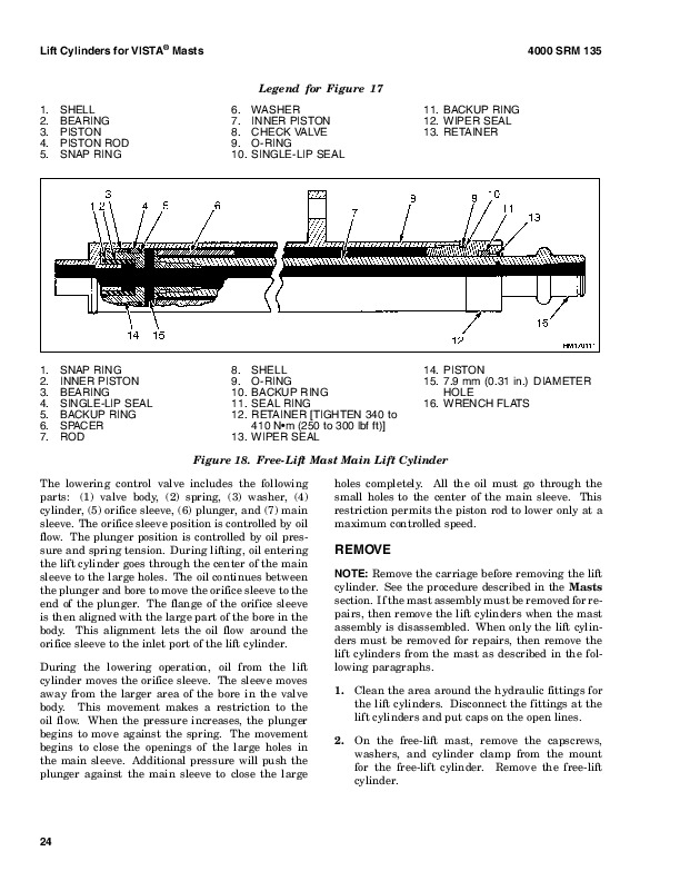
        Lowering…..478
        Lowering Control Valves…..478
      Repairs…..478
        General…..478
        Hydraulic Module, Remove…..478
        Hydraulic Module, Install…..479
        Remote Control Valve…..479
          Remove…..479
          Disassemble…..479
          Clean and Inspect…..480
          Assemble…..480
          Install…..482
          Adjust…..482
        Main Control Valves…..482
          Remove…..482
          Disassemble…..482
          Clean and Inspect…..484
          Assemble…..484
          Install…..484
        Lift Manifold…..485
          Remove…..485
          Clean and Inspect…..485
          Assemble and Install…..485
      Checks and Adjustments…..486
        Pilot Pressure, Check…..486
        Main Control Valves Relief Pressure, Check…..487
        Two-Speed Cartridge, Check…..487
    Tilt Control Circuit…..487
      Description…..487
      Operation…..488
        Tilt Spool…..488
        Relief Valves in Main Control Valve…..488
        Relief Valves, Tilt Lock…..489
      Repairs…..489
        General…..489
        Relief Valves, Tilt Lock, Disassemble…..489
        Clean and Inspect…..490
      Checks and Adjustments…..490
        Main Control Valve Relief Pressure, Check…..490
    Flow Control Valves Repair…..490
      Description…..490
        Accumulator Charge Valve…..490
        Relief Valves…..492
        Pressure Reduction Valves…..492
      Repairs…..492
        Accumulator Charge Valve…..492
        Relief Valve…..492
        Pressure Reduction Valves…..493
      Checks and Adjustments…..493
        Relief Valves, Check and Adjust…..493
        Pressure Reduction Valves Check…..493
    Solenoid Valves Repair…..494
      Description…..494
        Directional Control Valve, Carriage/Attachment…..494
      Repairs…..495
        Directional Control Valve, Carriage/Attachment…..495
          Remove…..495
          Disassemble…..495
          Clean and Inspect…..497
          Assemble…..497
          Install…..499
        Return Control Solenoid Valves…..499
          Remove…..499
          Install…..500
        Return Control Solenoid…..500
          Remove…..500
          Install…..500
        Carriage Solenoid Valves…..501
          Remove…..501
          Disassemble…..502
          Clean and Inspect…..502
          Assemble…..502
          Install…..502
      Over Lowering Interrupt…..502
      Lift Interrupt…..502
      Checks and Adjustments…..503
    Torque Specifications…..503
      Control Valves…..503
      Remote Control Valve…..503
      Control Valve, Carriage/Attachment…..503
      Carriage Solenoid Valve…..503
    Specifications…..503
      Hydraulic Pump Output at 2500 rpm and 13.8 MPa ( 2000 psi)…..503
      Pressure Reduction Valves…..503
      Relief Pressures at 2500 rpm…..503
      Main Hydraulic Filters…..504
      Tank Capacity…..504
    Troubleshooting…..504
      Control Valves…..504
      Remote Control Valve…..507
      Flow Control Valves…..507
      Accumulator Charge Valve and Accumulator…..507
      Pressure Reduction Valve 2.1 MPa ( 300 psi)…..507
      Pressure Reduction Valve 10.3 MPa ( 1500 psi)…..508
      Solenoid Valves…..509
      Control Valve for Carriage and Attachment…..509
  tables…..466
    Table 1. Accumulator Charge Valve Pressures…..473
hyster-897934-11-01-srm0626…..524
  toc…..524
    Cooling System…..524
    Safety Precautions Maintenance and Repair…..525
    General…..528
    Description…..529
      Radiator…..529
      Radiator Cap…..529
      Thermostat…..529
      Water Pump…..530
      Fan and Fan Shroud…..530
    Cooling System Checks…..530
      Radiator…..530
      Thermostat…..530
      Water Pump…..531
      Exhaust Leaks…..531
      Fan and Fan Shroud…..531
    Radiator Cleaning…..531
      Drain…..531
      Clean…..531
      Fill…..532
    Troubleshooting…..533
hyster-899784-10-03-srm0002…..536
  toc…..536
    Alternator with Regulator…..536
    Safety Precautions Maintenance and Repair…..537
    General…..540
    Description…..540
    Alternator Repair…..542
      Alternator Type A…..542
        Remove and Disassemble…..542
        Clean…..543
        Assemble…..544
        Install…..544
      Alternator Type B…..547
        Remove and Disassemble…..547
        Clean…..547
        Assemble…..548
        Install…..549
    General Check and Adjustment…..550
    Low Output Check (Type A or Type B)…..550
    High Output Check (Type A or Type B)…..552
    Brushes Circuit Check…..553
      Delco Alternators…..553
      Motorola Alternators…..554
    Diodes Check…..555
    Diode Bridge Check…..555
      Delco and Leece-Neville Alternators…..555
      Motorola Alternators…..555
    Rotor Field Winding Check…..556
    Stator Windings Check…..557
    Voltage Regulator Check…..557
    Troubleshooting…..557
hyster-910030-11-03-srm0047…..562
  toc…..562
    Planetary Gear Axle…..562
    Safety Precautions Maintenance and Repair…..563
    General…..566
    Description…..566
    Operation…..567
    Planetary Gear Axle Repair…..568
      Remove…..568
      Disassemble…..568
        Planetary Axle, Disassemble…..571
      Assemble and Install…..575
        Planetary Axle, Assemble…..576
    Torque Specifications…..581
    Troubleshooting…..584
  tables…..562
    Table 1. Axle-to-Frame Fasteners…..575
    Table 2. Standard Torque Values for Axle Fasteners…..581
    Table 3. Drive Wheel Nut Torque…..581
    Differential…..604
    Safety Precautions Maintenance and Repair…..605
    General…..608
    Description…..608
    Differential Repair…..608
      Remove…..608
        Differential Carrier From Axle Housing, Remove…..608
        Differential and Ring Gear From Differential Carrier, Remove…..612
        Drive Pinion and Pinion Carrier From Differential Carrier, Remov…..614
      Disassemble…..615
        Differential and Ring Gear Assembly, Disassemble…..615
        Drive Pinion and Pinion Carrier, Disassemble…..617
      Clean and Inspect…..619
      Assemble…..620
        Pinion, Bearings, and Pinion Carrier, Assemble…..620
        Pinion Bearings, Adjust Preload…..621
          Press Method…..621
          Yoke or Flange Method…..621
        Triple-Lip Seal, Install…..622
        Pinion Carrier Shim Set, Adjust Thickness (Depth of Pinion)…..623
        Differential and Ring Gear, Assemble…..625
        Differential Gears Rotating Torque, Check…..628
        Differential and Ring Gear Assembly, Install…..629
        Differential Bearings, Preload Adjust…..630
        Ring Gear, Runout Check…..631
        Ring Gear Backlash, Adjust…..631
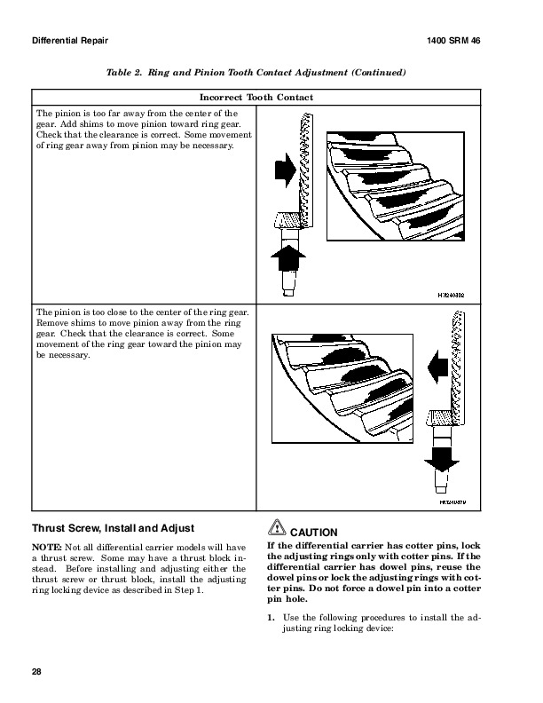
        Gear Set, Tooth Contact Pattern Check…..633
        Thrust Screw, Install and Adjust…..635
      Install…..636
        Differential Assembly Into Axle Housing, Install…..636
    Specifications…..638
    Troubleshooting…..642
  tables…..604
    Table 1. Ring Gear Backlash Adjustment Specifications…..632
    Table 2. Ring and Pinion Tooth Contact Adjustment…..634
    Table 3. General Specifications…..638
    Table 4. Rivet Installation Pressure…..638
    Table 5. Pinion Adjustment…..638
    Table 6. Pinion Preload Pressure…..639
    Table 7. Torque Specifications…..640
    Table 8. Torque Specifications for Metric Hardware…..641
    Table 9. Torque Specifications for Metric (Fine) Hardware…..641
hyster-910091-10-03-srm0097…..646
  toc…..646
    Hydraulic Gear Pumps…..646
    Safety Precautions Maintenance and Repair…..647
    Description…..650
    Operation…..651
      Flow Control Valve…..651
      Relief Valve…..652
    Hydraulic Gear Pump Repair…..652
      Remove…..652
      Disassemble…..653
      Clean…..653
      Inspect…..654
      Assemble…..657
      Install…..659
    Pump Output Check…..659
      Method No. 1…..659
      Method No. 2…..660
    Hydraulic System Air Check…..661
    Troubleshooting…..662
hyster-910102-10-03-srm0103…..668
  toc…..668
    Tilt Cylinders…..668
    Safety Precautions Maintenance and Repair…..669
    General…..672
    Description…..672
    Tilt Cylinder Repair…..672
      Remove…..672
      Disassemble…..672
      Clean…..672
      Assemble…..673
        Tilt Cylinders With O-Ring or Single-Lip Seals…..673
        Tilt Cylinders for XM and XMS Models…..674
        Tilt Cylinders for H700-800A and Early Model H700-920B…..675
      Install…..676
        Tilt Cylinders Using Chevron Packing…..677
          Install…..678
    Tilt Cylinder Leak Check…..680
    Tilt Cylinder Stroke and Mast Tilt Angle Adjustment…..681
    Torque Specifications…..682
      Piston Rod Nut…..682
      Retainer…..683
    Troubleshooting…..685
  tables…..668
    Table 1. Movement Rates (Maximum) for Tilt Cylinders…..681
hyster-910107-02-01-srm0106…..688
  toc…..688
    Starter…..688
    Safety Precautions Maintenance and Repair…..689
    General…..692
    Description and Operation…..692
    Starter Repair…..694
      Remove…..694
      Disassemble…..694
      Clean…..695
      Assemble…..695
      Install…..696
    General Checks and Adjustments…..696
    Troubleshooting…..699
hyster-910110-12-03-srm0143…..704
  toc…..704
    Instrument Panel Indicators and Senders…..704
    Safety Precautions Maintenance and Repair…..705
    General…..708
    Description…..709
      Steering Column Gauges, Meters, and Indicators…..709
      LED Display Panel…..709
        Battery Discharge Indicators…..709
        Brush Wear Indicators…..716
        Motor Temperature Indicators…..716
      LX Series Display Panel…..718
        Hourmeter Functions…..718
        Battery Indicator Function…..719
        Status Code Function…..720
      ZX Series Display Panels…..720
        Display Panel…..720
        Basic Display Panels…..720
        Performance Display…..723
        Brush Wear Indicators…..726
    Adjustments – General…..727
    Replacement – General Information…..727
    Meter Replacement…..728
    Sender Replacement…..729
      Fuel Level Sender…..729
      Pressure and Temperature Sender…..729
    ITW Display Panel Replacement…..730
      Remove…..730
    Column Mount Display Panel (EV-100/200ZX Motor Controllers) Repl…..731
      Remove…..731
      Display Panel Assembly, Replace…..731
      Indicator LEDs…..732
      Battery Indicators…..732
      Digital Display (Performance Display Panel Only)…..732
      Status Code or Performance Level Switches and Indicator LEDs (Pe…..732
      Basic Display Panel, Replace Parts…..732
      Performance Display Panel, Replace Parts…..734
    Dash Mount Display Panel (EV100/200ZX Motor Controllers) Replace…..735
      Remove and Replace…..735
    Specifications…..735
      Meter Specifications…..735
      Sender Specifications…..736
    Troubleshooting…..736
      Meter…..736
hyster-910442-03-03-srm0231…..740
    Metric and Inch (SAE) Fasteners…..740
    General…..744
      Threaded Fasteners…..744
      Nomenclature, Threads…..744
      Strength Identification…..745
      Cotter (Split) Pins…..745
      Fastener Torque Tables…..750
      Conversion Table…..752
  tables…..740
    Table 1. Bolts and Screws…..746
    Table 2. Studs and Nuts…..747
    Table 3. Torque Nuts…..748
    Table 4. Torque Nuts With Nylon Insert…..749
    Table 5. Torque Values for Metric Fasteners*…..750
    Table 6. Torque Values for Inch Fasteners*…..751
    Table 7. Conversion Table for Metric and English units…..752
    Table 8. Cotter Pin Dimensional Data…..753

Hyster H440-700F/FS (E008) Repair Service Manual


INSTANT DOWNLOAD


Posted on

Hyster H40-60XL (B177 / C177) Repair Service Manual


INSTANT DOWNLOAD


Complete service repair manual for Hyster H40-60XL (B177 / C177) Forklifts Trucks, with all the shop information to maintain, diagnose, repair, and rebuild like professional mechanics.

Hyster H40XL-H60XL (B177 / C177) workshop service & repair manual includes:
* Numbered table of contents easy to use so that you can find the information you need fast.
* Detailed sub-steps expand on repair procedure information
* Numbered instructions guide you through every repair procedure step by step.
* Troubleshooting and electrical service procedures are combined with detailed wiring diagrams for ease of use.
* Notes, cautions and warnings throughout each chapter pinpoint critical information.
* Bold figure number help you quickly match illustrations with instructions.
* Detailed illustrations, drawings and photos guide you through every procedure.
* Enlarged inset helps you identify and examine parts in detail.

897414 – Hyster H40-60XL (B177 / C177) Service Manual.pdf

Total Pages: 868 pages
File Format: PDF (Internal Links, Bookmarked, Table of Contents, Searchable, Printable, high quality)
Language: English

 
Section
Part No.
SRM Number Rev Date
FRAME
910165
 0100 SRM 0137
01/97
GM ENGINE
899766
 0600 SRM 0003
08/03
MAZDA M4-121G ENGINE
899767
  0600 SRM 0066
 04/96
ISUZU C240 (2.4L) ENGINE
899768
  0600 SRM 0070
 04/93
COOLING SYSTEM
897934
  0700 SRM 0626
11/01
ROCHESTER CARBURETOR (GM ENG)
910057
  0900 SRM 0011
02/97
LPG FUEL SYSTEM
899772
  0900 SRM 0015
 09/93
GASOLINE CARBURETOR (MAZDA)
910168
 0900 SRM 0129
 09/93
SINGLE-SPEED PS TRANS – DESCR / OPER (T41,T42,T43)
899323
1300 SRM 0255
01/97
SINGLE-SPEED PS TRANS – REPAIR (T41,T42,T43)
899324
1300 SRM 0256
04/94
DRIVE AXLE
910171
1400 SRM 0085
02/97
STEERING AXLE
899775
1600 SRM 0010
01/96
STEERING CONTROL UNIT
910458
1600 SRM 0257
07/00
STEERING SYSTEM
897407
1600 SRM 0459
05/94
BRAKE SYSTEM
897405
1800 SRM 0458
02/94
HYDRAULIC SYSTEM and GEAR PUMP
899780
1900 SRM 0130
03/97
HYDRAULIC PUMP DRIVE ASSEMBLY
897121
1900 SRM 0339
10/03
MAIN CONTROL VALVE
899782
2000 SRM 0077
07/00
TILT CYLINDERS
910102
2100 SRM 0103
10/03
ALTERNATOR
899784
09/02
STARTER
910107
2200 SRM 0106
02/01
ELECTRICAL SYSTEM  (MAZDA)
899791
2200 SRM 0132
02/97
ELECTRICAL SYSTEM  (ISUZU)
899792
2200 SRM 0134
06/93
INSTRUMENT PANEL INDICATORS and SENDERS
910110
2200 SRM 0143
12/03
MSTS – GM LPG (EARLY CONTROL MODULES)
897412
2200 SRM 0463
04/93
MSTS – GM LPG (LATER CONTROL MODULES)
1473385
2200 SRM 0765
11/01
LIFT CYLINDERS
910119
4000 SRM 0135
10/03
VISTA MASTS – DESCRIPTION
899237
4000 SRM 0222
 12/92
VISTA MASTS – REPAIR
910435
4000 SRM 0223
01/97
CAPACITIES and SPECIFICATIONS
899803
8000 SRM 0048
05/97
INCH (SAE) and METRIC FASTENERS
910442
8000 SRM 0231
03/03
PERIODIC MAINTENANCE
910757
8000 SRM 0259
04/97
DIAGRAMS
897410
8000 SRM 0461
03/97
 
PART NO. 897414
Rev. 12/03

    Microprocessor Spark Timing System (MSTS)…3
    Safety Precautions Maintenance and Repair…4
    General…7
    Description…8
      What MSTS Does…8
      How MSTS Begins Operation…8
    Operation…9
      Distributor…9
      Ignition Coil…9
      Ignition Module…9
      When Engine Is Being Started…10
      When Engine Is Running…11
      Manifold Absolute Pressure (MAP) Sensor…12
      Engine Coolant Temperature (ECT) Sensor…12
      MSTS Module Corrections…13
    Troubleshooting…14
      General…14
      Tools and Test Equipment…16
      MSTS…17
      Troubleshooting Procedure…17
        Where to Start…17
        Visual/Physical Inspection…17
        Knowledge/Tools Required…17
        Damage from Static Discharge (Static Electricity)…17
      Troubleshooting Information…18
        Malfunction Indicator Lamp (MIL)…18
        Connecting CodeMate Tester…18
        Reading Diagnostic Trouble Codes (DTC)…19
        Clearing Diagnostic Trouble Codes (DTC's)…20
      On-Board Diagnostic (OBD) System Check…20
        Test Description…20
    No Malfunction Indicator Lamp…22
      Circuit Description…22
      Test Description…22
    No DTC-12, Malfunction Indicator Lamp ON…24
      Circuit Description…24
      Test Description…24
    Starter Rotates Engine, Engine Does Not Run…25
      Test Description…25
    DTC-14 Engine Coolant Temperature (ECT) (Low Temperature Indicat…29
      Circuit Description…29
      Test Description…29
    DTC-15 Engine Coolant Temperature Sensor (ECT) (High Temperature…31
      Circuit Description…31
      Test Description…31
    DTC-34 Manifold Absolute Pressure (MAP) Sensor…33
      Circuit Description…33
      Test Description…33
    DTC-41 Electronic Spark Timing (EST) Open Circuit…36
      Circuit Description…36
      Test Description…36
    DTC-42 Electronic Spark Timing (EST) Grounded Circuit…38
      Circuit Description…38
      Test Description…38
    DTC-51 MSTS Failure…40
      Circuit Description…40
    Distributor Repair…40
      Remove…40
      Disassemble…41
      Inspect…41
      Assemble…41
      Install…42
      Ignition Timing…42
    Ignition Module Repair…43
      Test For Fault…43
      Replace…44
    Sensing Coil Repair…44
      Test For Fault…44
      Replace…44
    Ignition Coil Repair…45
      Test For Fault…45
      Remove…45
      Install…45
    MSTS Module Repair…46
      Remove…46
      Install…46
    ECT Sensor Replacement…46
    MAP Sensor Replacement…47
  tables…3
    Table 1. MSTS Module Connections…15
    Table 2. Pressure Conversion Chart…16
    Table 3. MSTS Diagnostic Codes…18
hyster-897121-10-03-srm0339…51
  toc…51
    Hydraulic Pump Drive Assembly…51
    Safety Precautions Maintenance and Repair…52
    General…55
    Description…55
    Hydraulic Pump Drive Assembly Repair…57
      Remove and Disassemble…57
      Clean…58
      Inspect…58
      Assemble and Install…58
    Troubleshooting…59
      Radiator Cap…184
      Thermostat…184
      Water Pump…185
      Fan and Fan Shroud…185
    Cooling System Checks…185
      Radiator…185
      Thermostat…185
      Water Pump…186
      Exhaust Leaks…186
      Fan and Fan Shroud…186
    Radiator Cleaning…186
      Drain…186
      Clean…186
      Fill…187
    Cylinder Head and Valve Mechanism Repair…293
      Cylinder Head, Remove…293
      Cylinder Head, Disassemble…293
      Clean and Inspect…293
      Valves and Valve Seats…296
      Studs for Rocker Arms…296
      Hydraulic Valve Lifters, Replace…297
      Hydraulic Valve Lifters, Clean and Inspect…297
      Cylinder Head, Assemble…297
      Cylinder Head, Install…297
      Valve Clearance, Adjust…298
      Rocker Arm Cover, Install…299
    Timing Gear Cover Repair…299
      Remove…299
      Install…300
    Camshaft Repair…301
      Remove…301
      Inspect…301
      Camshaft Bearing…302
        Remove…302
        Install…302
    Distributor Repair…303
      Remove…303
      Install…303
    Lubrication System Repair…304
      Oil Sump…304
        Remove…304
        Install…304
      Oil Pump…304
        Remove…304
        Disassemble and Repair…304
        Assemble…305
        Install…305
    Piston and Connecting Rod Assemblies Repair…305
      Connecting Rod Bearings, Replace…305
      Piston and Connecting Rod Assemblies, Remove…306
      Piston and Connecting Rod Assemblies, Disassemble…307
      Piston, Clean and Inspect…307
      Cylinder Bores, Inspect and Repair…307
      Piston Rings, Inspect…308
      Piston and Connecting Rod Assemblies, Assemble…308
      Piston and Connecting Rod Assemblies, Install…310
    Crankshaft Repair…310
      Main Bearings, Replace…310
      Oil Seal for Rear Main Bearing, Replace (GM 4-181 and 3.0L Only)…311
      Oil Seal for Rear Main Bearing, Replace (Engines That Have Two-P…311
      Remove…313
      Inspect and Repair…313
      Main Bearing and Journal Clearance, Check…314
      Install…314
    Flywheel and Flywheel Housing Repair…315
      Remove…316
      Ring Gear, Replace…317
      Install…317
    Cooling System Repair…317
      Coolant Pump…317
      Fan Drive…317
      Viscous Fan Drive…317
    Engine Specifications…319
      Engine Data…319
      Cylinder Head…320
      Hydraulic Valve Lifter…320
      Camshaft…321
      Pistons…322
      Cylinder Bore…322
      Crankshaft…323
      Connecting Rods…323
      Cooling System…324
      Lubrication System…324
    Torque Specifications…324
    Troubleshooting…325
      Remove…591
      Disassemble…591
      Clean…591
      Assemble…592
        Tilt Cylinders With O-Ring or Single-Lip Seals…592
        Tilt Cylinders for XM and XMS Models…593
        Tilt Cylinders for H700-800A and Early Model H700-920B…594
      Install…595
        Tilt Cylinders Using Chevron Packing…596
          Install…597
    Tilt Cylinder Leak Check…599
    Tilt Cylinder Stroke and Mast Tilt Angle Adjustment…600
    Torque Specifications…601
      Piston Rod Nut…601
      Retainer…602
    Troubleshooting…604
  tables…587
    Table 1. Movement Rates (Maximum) for Tilt Cylinders…600
hyster-910107-02-01-srm0106…607
  toc…607
    Starter…607
    Safety Precautions Maintenance and Repair…608
    General…611
    Description and Operation…611
    Starter Repair…613
      Remove…613
      Disassemble…613
      Clean…614
      Assemble…614
      Install…615
    General Checks and Adjustments…615
    Troubleshooting…618
hyster-910110-12-03-srm0143…623
  toc…623
    Instrument Panel Indicators and Senders…623
    Safety Precautions Maintenance and Repair…624
    General…627
    Description…628
      Steering Column Gauges, Meters, and Indicators…628
      LED Display Panel…628
        Battery Discharge Indicators…628
        Brush Wear Indicators…635
        Motor Temperature Indicators…635
      LX Series Display Panel…637
        Hourmeter Functions…637
        Battery Indicator Function…638
        Status Code Function…639
      ZX Series Display Panels…639
        Display Panel…639
        Basic Display Panels…639
        Performance Display…642
        Brush Wear Indicators…645
    Adjustments – General…646
    Replacement – General Information…646
    Meter Replacement…647
    Sender Replacement…648
      Fuel Level Sender…648
      Pressure and Temperature Sender…648
    ITW Display Panel Replacement…649
      Remove…649
    Column Mount Display Panel (EV-100/200ZX Motor Controllers) Repl…650
      Remove…650
      Display Panel Assembly, Replace…650
      Indicator LEDs…651
      Battery Indicators…651
      Digital Display (Performance Display Panel Only)…651
      Status Code or Performance Level Switches and Indicator LEDs (Pe…651
      Basic Display Panel, Replace Parts…651
      Performance Display Panel, Replace Parts…653
    Dash Mount Display Panel (EV100/200ZX Motor Controllers) Replace…654
      Remove and Replace…654
    Specifications…654
      Meter Specifications…654
      Sender Specifications…655
    Troubleshooting…655
      Meter…655
hyster-910119-10-03-srm0135…659
  toc…659
    Lift Cylinders…659
    Safety Precautions Maintenance and Repair…660
    Safety Procedures When Working Near Mast…663
    General…667
    Description…667
      Lowering Control Valve…667
      Cylinders (General)…670
      Cylinders (H520-620B, H700-800A)…670
        Retainer, Install…670
      Cylinders (H360-460B)…672
      Cylinders (Two-Speed)…674
    Lift Cylinder Repair…676
      Lift Cylinder Removal Without Removing Mast…676
        Standard Masts With Main Lift Cylinder Fastened to Crossmember o…676
        Standard and Full Free-Lift Masts With Lift Cylinder Fastened to…676
        Masts That Have Two Cylinders, Main Lift Cylinder and Free-Lift …676
      Disassemble…678
      Assemble…678
      Lift Cylinder Installation in Mast…680
        Standard Masts With Main Lift Cylinder Fastened to Crossmember o…680
        Standard and Full Free-Lift Masts With Lift Cylinder Fastened to…680
      Chevron-Style Packing…680
        Chevron-Style Packing Installation on Piston…681
        Chevron-Style Packing Installation in Packing Gland…683
    Lift Cylinders for VISTA® Masts…684
      Description…684
        Lowering Control Valve…684
      Remove…686
      Disassemble…687
      Assemble…688
      Install…689
        Main Lift Cylinders…689
        Free-Lift Cylinder…689
    Lift System Leak Check…690
    Specifications…691
    Troubleshooting…692
  tables…659
      Fastener Torque Tables…785
      Conversion Table…787
  tables…775
    Table 1. Bolts and Screws…781
    Table 2. Studs and Nuts…782
    Table 3. Torque Nuts…783
    Table 4. Torque Nuts With Nylon Insert…784
    Table 5. Torque Values for Metric Fasteners*…785
    Table 6. Torque Values for Inch Fasteners*…786
    Table 7. Conversion Table for Metric and English units…787
    Table 8. Cotter Pin Dimensional Data…788

Hyster H40-60XL (B177 / C177) Repair Service Manual


INSTANT DOWNLOAD


Posted on

Hyster H800-1050C (C117) Repair Service Manual


INSTANT DOWNLOAD


Complete service repair manual for Hyster H800-1050C (C117) Forklifts Trucks, with all the shop information to maintain, diagnose, repair, and rebuild like professional mechanics.

Hyster H800C-H1050C (C117) workshop service & repair manual includes:
* Numbered table of contents easy to use so that you can find the information you need fast.
* Detailed sub-steps expand on repair procedure information
* Numbered instructions guide you through every repair procedure step by step.
* Troubleshooting and electrical service procedures are combined with detailed wiring diagrams for ease of use.
* Notes, cautions and warnings throughout each chapter pinpoint critical information.
* Bold figure number help you quickly match illustrations with instructions.
* Detailed illustrations, drawings and photos guide you through every procedure.
* Enlarged inset helps you identify and examine parts in detail.

897399 – Hyster H800-1050C (C117) Service Manual.pdf

Total Pages: 742 pages
File Format: PDF
Language: English

 
Section
Part No.
SRM Number Rev Date
FRAME
897635
  0100 SRM 0428
03/97
PERKINS 2006-12T1 ENGINE
897363
  0600 SRM 0427
 06/94
COOLING SYSTEM
897934
  0700 SRM 0626
11/01
THREE-SPEED PS TRANS – DESCR / OPER
897260
1300 SRM 0391
 07/95
THREE-SPEED PS TRANSMISSION – REPAIR
897261
1300 SRM 0392
 08/90
DIFFERENTIAL
910072
1400 SRM 0046
11/03
PLANETARY GEAR AXLE
910030
1400 SRM 0047
11/03
STEERING AXLE
910031
1600 SRM 0071
07/97
STEERING SYSTEM
897367
1600 SRM 0429
04/97
BRAKE SYSTEM – AIR
897359
1800 SRM 0425
 06/89
BRAKE SYSTEM – HYDRAULIC
897433
1800 SRM 0472
 04/92
HYDRAULIC GEAR PUMPS
910091
1900 SRM 0097
10/03
HYDRAULIC SYSTEM  (EARLY UNITS)
897369
1900 SRM 0430
 07/89
HYDRAULIC SYSTEM  (LATER UNITS)
897432
1900 SRM 0471
 07/91
TILT CONTROL VALVE
910101
2100 SRM 0102
 07/94
TILT CYLINDERS
910102
2100 SRM 0103
10/03
INSTRUMENT PANEL INDICATORS & SENDERS
910110
2200 SRM 0143
12/03
ELECTRICAL SYSTEM
897370
2200 SRM 0431
03/97
MAST
897371
4000 SRM 0432
03/97
EXTENDABLE CONTAINER ATTACHMENT
910457
5000 SRM 0265
11/97
FIXED CONTAINER ATTACHMENT
910466
5000 SRM 0266
11/97
INCH (SAE) AND METRIC FASTENERS
910442
8000 SRM 0231
03/03
PERIODIC MAINTENANCE
897361
8000 SRM 0426
 04/93
CAPACITIES AND SPECIFICATIONS
897375
8000 SRM 0434
 07/91
DIAGRAMS
897376
8000 SRM 0435
02/97
 
PART NO. 897399
Rev. 12/03


    Cooling System….502
    Safety Precautions Maintenance and Repair….503
    General….506
    Description….507
      Radiator….507
      Radiator Cap….507
      Thermostat….507
      Water Pump….508
      Fan and Fan Shroud….508
    Cooling System Checks….508
      Radiator….508
      Thermostat….508
      Water Pump….509
      Exhaust Leaks….509
      Fan and Fan Shroud….509
    Radiator Cleaning….509
      Drain….509
      Clean….509
      Fill….510
    Troubleshooting….511
hyster-910030-11-03-srm0047….514
  toc….514
    Planetary Gear Axle….514
    Safety Precautions Maintenance and Repair….515
    General….518
    Description….518
    Operation….519
    Planetary Gear Axle Repair….520
      Remove….520
      Disassemble….520
        Planetary Axle, Disassemble….523
      Assemble and Install….527
        Planetary Axle, Assemble….528
    Torque Specifications….533
    Troubleshooting….536
  tables….514
    Table 1. Axle-to-Frame Fasteners….527
    Table 2. Standard Torque Values for Axle Fasteners….533
    Table 3. Drive Wheel Nut Torque….533
        Pinion Bearings, Adjust Preload….573
          Press Method….573
          Yoke or Flange Method….573
        Triple-Lip Seal, Install….574
        Pinion Carrier Shim Set, Adjust Thickness (Depth of Pinion)….575
        Differential and Ring Gear, Assemble….577
        Differential Gears Rotating Torque, Check….580
        Differential and Ring Gear Assembly, Install….581
        Differential Bearings, Preload Adjust….582
        Ring Gear, Runout Check….583
        Ring Gear Backlash, Adjust….583
        Gear Set, Tooth Contact Pattern Check….585
        Thrust Screw, Install and Adjust….587
      Install….588
        Differential Assembly Into Axle Housing, Install….588
    Specifications….590
    Troubleshooting….594
  tables….556
    Table 1. Ring Gear Backlash Adjustment Specifications….584
    Table 2. Ring and Pinion Tooth Contact Adjustment….586
    Table 3. General Specifications….590
    Table 4. Rivet Installation Pressure….590
    Table 5. Pinion Adjustment….590
    Table 6. Pinion Preload Pressure….591
    Table 7. Torque Specifications….592
    Table 8. Torque Specifications for Metric Hardware….593
    Table 9. Torque Specifications for Metric (Fine) Hardware….593
hyster-910091-10-03-srm0097….598
  toc….598
    Hydraulic Gear Pumps….598
    Safety Precautions Maintenance and Repair….599
    Description….602
    Operation….603
      Flow Control Valve….603
      Relief Valve….604
    Hydraulic Gear Pump Repair….604
      Remove….604
      Disassemble….605
      Clean….605
      Inspect….606
      Assemble….609
      Install….611
    Pump Output Check….611
      Method No. 1….611
      Method No. 2….612
    Hydraulic System Air Check….613
    Troubleshooting….614
hyster-910101-07-94-srm0102….620
  ….620
  ….621
  ….622
  ….623
  ….624
  ….625
  ….626
  ….627
  ….628
  ….629
hyster-910102-10-03-srm0103….630
  toc….630
    Tilt Cylinders….630
    Safety Precautions Maintenance and Repair….631
    General….634
    Description….634
    Tilt Cylinder Repair….634
      Remove….634
      Disassemble….634
      Clean….634
      Assemble….635
        Tilt Cylinders With O-Ring or Single-Lip Seals….635
        Tilt Cylinders for XM and XMS Models….636
        Tilt Cylinders for H700-800A and Early Model H700-920B….637
      Install….638
        Tilt Cylinders Using Chevron Packing….639
          Install….640
    Tilt Cylinder Leak Check….642
    Tilt Cylinder Stroke and Mast Tilt Angle Adjustment….643
    Torque Specifications….644
      Piston Rod Nut….644
      Retainer….645
    Troubleshooting….647
  tables….630
    Table 1. Movement Rates (Maximum) for Tilt Cylinders….643
hyster-910110-12-03-srm0143….650
  toc….650
    Instrument Panel Indicators and Senders….650
    Safety Precautions Maintenance and Repair….651
    General….654
    Description….655
      Steering Column Gauges, Meters, and Indicators….655
      LED Display Panel….655
        Battery Discharge Indicators….655
        Brush Wear Indicators….662
        Motor Temperature Indicators….662
      LX Series Display Panel….664
        Hourmeter Functions….664
        Battery Indicator Function….665
        Status Code Function….666
      ZX Series Display Panels….666
        Display Panel….666
        Basic Display Panels….666
        Performance Display….669
        Brush Wear Indicators….672
    Adjustments – General….673
    Replacement – General Information….673
    Meter Replacement….674
    Sender Replacement….675
      Fuel Level Sender….675
      Pressure and Temperature Sender….675
    ITW Display Panel Replacement….676
      Remove….676
    Column Mount Display Panel (EV-100/200ZX Motor Controllers) Repl….677
      Remove….677
      Display Panel Assembly, Replace….677
      Indicator LEDs….678
      Battery Indicators….678
      Digital Display (Performance Display Panel Only)….678
      Status Code or Performance Level Switches and Indicator LEDs (Pe….678
      Basic Display Panel, Replace Parts….678
      Performance Display Panel, Replace Parts….680
    Dash Mount Display Panel (EV100/200ZX Motor Controllers) Replace….681
      Remove and Replace….681
    Specifications….681
      Meter Specifications….681
      Sender Specifications….682
    Troubleshooting….682
      Meter….682
hyster-910442-03-03-srm0231….686
  toc….686
    Metric and Inch (SAE) Fasteners….686
    Safety Precautions Maintenance and Repair….687
    General….690
      Threaded Fasteners….690
      Nomenclature, Threads….690
      Strength Identification….691
      Cotter (Split) Pins….691
      Fastener Torque Tables….696
      Conversion Table….698
  tables….686
    Table 1. Bolts and Screws….692
    Table 2. Studs and Nuts….693
    Table 3. Torque Nuts….694
    Table 4. Torque Nuts With Nylon Insert….695
    Table 5. Torque Values for Metric Fasteners*….696
    Table 6. Torque Values for Inch Fasteners*….697
    Table 7. Conversion Table for Metric and English units….698
    Table 8. Cotter Pin Dimensional Data….699

Hyster H800-1050C (C117) Repair Service Manual


INSTANT DOWNLOAD


Posted on

Hyster H165-280XL (D007 / E007) & H300-360XL (C019 / D019) Repair Service Manual


INSTANT DOWNLOAD


Complete service repair manual for Hyster H165-280XL (D007 / E007) & H300-360XL (C019 / D019) Forklifts Trucks, with all the technical information to maintain, diagnose, repair, and rebuild like professional mechanics.

Hyster H165XL-H280XL (D007 / E007) & H300XL-H360XL (C019 / D019) workshop service & repair manual includes:
* Numbered table of contents easy to use so that you can find the information you need fast.
* Detailed sub-steps expand on repair procedure information
* Numbered instructions guide you through every repair procedure step by step.
* Troubleshooting and electrical service procedures are combined with detailed wiring diagrams for ease of use.
* Notes, cautions and warnings throughout each chapter pinpoint critical information.
* Bold figure number help you quickly match illustrations with instructions.
* Detailed illustrations, drawings and photos guide you through every procedure.
* Enlarged inset helps you identify and examine parts in detail.

897373 – Hyster H165-280XL (D007 / E007) & H300-360XL (C019 / D019) Service Manual.pdf

Total Pages: 1,024 pages
File Format: PDF (Internal Links, Bookmarked, Table of Contents, Searchable, Printable, high quality)
Language: English

 
Section
Part No.
SRM Number Rev Date
FRAME
897377
 0100 SRM 0436
05/95
PERKINS DIESEL ENGINE-1000 SERIES
897341
  0600 SRM 0412
08/97
GM V8-366 ENGINE
1452285
  0600 SRM 0674
03/97
PERKINS DIESEL ENGINE-1000 SERIES (AR, YG, YH)
1455747
0600 SRM 0705
09/03
COOLING SYSTEM
897934
 0700 SRM 0626
11/01
LPG FUEL SYSTEM
1452442
0900 SRM 0675
05/97
THREE-SPEED PS TRANS – DESCR / OPER
897378
1300 SRM 0437
02/95
THREE-SPEED PS TRANS – REPAIR
897379
1300 SRM 0438
09/94
THREE-SPEED PS TRANS – DESCR / OPER (HYSTER-T5
897498
1300 SRM 0517
11/99
THREE-SPEED PS TRANS – REPAIR (HYSTER-T50)
897499
1300 SRM 0518
11/99
AUTOSHIFT TRANSMISSION CONTROLLER
1473394
1300 SRM 0722
11/99
DIFFERENTIAL
910072
1400 SRM 0046
11/03
PLANETARY GEAR AXLE
897380
1400 SRM 0439
09/94
STEERING AXLE
897108
1600 SRM 0326
10/03
STEERING SYSTEM
897645
1600 SRM 0564
01/95
BRAKE SYSTEM
897382
1800 SRM 0441
02/95
AIR COMPRESSOR
897383
1800 SRM 0442
06/93
TU-FLO AIR COMPRESSOR (GM V8-366 ENG)
1454402
1800 SRM 0695
07/97
HYDRAULIC SYSTEM
897384
1900 SRM 0443
04/94
MAIN CONTROL VALVE
897385
2000 SRM 0444
02/95
TILT CONTROL VALVE
910101
2100 SRM 0102
07/94
TILT CYLINDERS
910102
2100 SRM 0103
10/03
ALTERNATOR
899784
2200 SRM 0002
10/03
STARTER
910107
2200 SRM 0106
02/01
HIGH ENERGY IGNITION SYSTEM
899788
2200 SRM 0107
03/02
INSTRUMENT PANEL INDICATORS and SENDERS
910110
2200 SRM 0143
12/03
MASTS
897386
4000 SRM 0445
08/01
EMPTY CONTAINER HANDLING ATTACHMENT
897416
4500 SRM 0465
04/94
INCH (SAE) AND METRIC FASTENERS
910442
8000 SRM 0231
03/03
PERIODIC MAINTENANCE
897343
8000 SRM 0433
05/97
CAPACITIES AND SPECIFICATIONS
897388
8000 SRM 0447
05/97
DIAGRAMS
897389
8000 SRM 0448
11/99
 
PART NO. 897373
Rev. 12/03

    Perkins Diesel Engines…75
    Safety Precautions Maintenance and Repair…76
    General…83
      General Safety Rules…83
    Description…84
      Engine Serial Number Codes…87
      Engine Data…87
    Engine Removal and Installation…89
      Lift Engine…89
    Cylinder Head Assembly Repair…89
      Valve Cover…89
        Remove…89
        Install…90
      Rocker Arm Assembly…90
        Remove…90
        Install…90
        Disassemble…90
        Inspect…90
        Assemble…91
      Valve Clearance Adjustments…91
        Four-Cylinder Engines…92
        Six-Cylinder Engines…92
      Valve Springs…92
      Cylinder Head Assembly…94
        Remove…94
        Install…96
      Valves and Valve Springs…100
        Remove…100
        Inspect…100
        Install…101
      Valve Guides…101
        Inspect…101
        Remove…102
        Install…102
      Cylinder Head and Valve Seats…102
        Inspect…102
        Repair…102
        New Valve Seats, Install…102
    Piston and Connecting Rod Assemblies Repair…104
      Rod Bearings…104
        Remove…105
        Install…105
      Piston and Connecting Rod Assembly…106
        Service Note…106
        Remove…106
        Install…107
      Piston Rings…108
        Remove…108
        Inspect…108
        Install…108
      Piston and Connecting Rod…109
        Disassemble…109
        Inspect…110
        How to Select Correct Replacements…110
        Install…111
      Piston Cooling Jets…111
        Remove…111
        Install…112
    Crankshaft Assembly Repair…112
      General…112
      Crankshaft Pulley…113
        Engine AR, Remove…113
        Engines YG and YH, Remove…113
        Inspect…114
        Engine AR, Install…114
        Engines YG and YH, Install…114
      Rear Oil Seal…115
        Replace…115
      Main Bearings…116
        Remove…116
        Inspect…117
        Install…117
      Thrust Washers…117
        Crankshaft Axial Movement, Check…117
        Remove…118
        Install…118
      Crankshaft…119
        Remove…119
        Inspect…119
        Install…119
      Flywheel…121
        Remove…121
        Ring Gear, Replace…121
        Install…121
      Flywheel Housing…122
        Remove…122
        Install…122
    Timing Case and Timing Gears Repair…123
      General…123
      Timing Case Cover…123
        Remove…123
        Install…124
      Front Oil Seal…124
        Remove…124
        Install…124
      Crankshaft Pulley Wear Sleeve…125
        Install…125
      Idler Gear and Hub…125
        Remove…125
        Install…126
      Air Compressor Drive, Bendix…127
        Disassemble…127
        Assemble…128
      Fuel Injection Pump Gear…128
        Remove…129
        Install…129
      Camshaft Gear…130
        Remove…130
        Install…130
      Crankshaft Gear…131
        Remove…131
        Install…131
      Timing Case…131
        Remove…131
        Install…132
      Camshaft and Tappets…133
        Remove…133
        Install…133
    Cylinder Block Assembly Repair…134
      Description…134
      Cylinder Block…134
        Disassemble…134
        Inspect…135
        Assemble…135
      Cylinder Bore (Four-Cylinder Engines)…136
      Cylinder Liner (Six-Cylinder Engines)…136
        Inspect…136
        Cylinder Liner Condition, Check…136
        Remove…137
        Service Liner, Install…138
        Partially Finished Liner, Install…139
    Engine Timing…140
      Description…140
        How to Set Number One Piston to TDC on Compression Stroke…141
        How to Set Number One Piston to TDC on Compression Stroke (Alter…142
        Valve Timing, Check…142
        Fuel Injection Pump Timing, Check…143
    Turbocharger – Engine YH Repair…144
      General…144
        Remove…144
        Install…144
        Impeller and Compressor Housing, Clean…145
    Lubrication System Repair…146
      General…146
      Oil Filter, Replace…146
      Filter Head…147
        Remove and Install…147
      Oil Sump…147
        Remove…147
        Install…148
      Oil Pump…148
        Remove…148
        Inspect…148
        Install…149
      Relief Valve…149
        Remove…149
        Disassemble…150
        Inspect…150
        Assemble…150
        Install…150
      Idler Gear Shaft, Replace…151
        Remove…151
        Remove (Alternative)…151
        Install…152
        Install (Alternative)…152
        Install (Alternative for Four-Cylinder Engines Only)…153
    Fuel System Repair…153
      Description…153
      Fuel Injection Pump…154
        Remove…154
        Install…155
        Check and Adjust…156
      Fuel System, Remove Air…156
      Fuel Filter, Replace…157
        Canister Type…158
        Quick Release Canister Type…158
      Fuel Injectors…159
        Remove…159
        Inspect…160
        Install…160
      Fuel Pump…161
        Remove…161
        Disassemble…161
        Assemble…161
        Install…162
        Test…162
    Cooling System Repair…163
      General…163
      Thermostat…163
        Remove…163
        Install…163
        Test…164
      Coolant Pump…164
        Remove…164
        Disassemble…164
        Assemble…166
        Install…168
      Fan and Fan Drive…169
        Remove…169
        Install…169
      Oil Cooler (Six-Cylinder Engines)…170
        Remove…170
        Disassemble and Assemble…170
        Install…170
        Oil Cooler By-Pass Valve…170
    Electrical Equipment Repair…171
      Drive Belts…171
      Alternator…172
        Remove…172
        Install…172
      Starter Motor…172
        Remove…172
        Install…172
      Cold Start Aid…172
    Air Compressor – Engines YG and YH…172
      General…172
      Repair…173
        Remove…173
        Install…173
    Rotary Exhauster Replacement…174
      Remove…174
      Clean…174
      Install…174
    Engine Specifications…175
      Cylinder Head Assembly…175
      Piston and Connecting Rods…178
      Crankshaft Assembly…181
        Crankshaft Overhaul…182
      Timing Case and Drive Assembly…184
      Engine Block Assembly…185
      Turbocharger…188
      Lubrication System…188
      Fuel System…190
      Cooling System…192
      Flywheel and Housing…192
      Electrical Equipment…193
    Torque Specifications…194
      Cylinder Head Assembly…194
      Piston and Connecting Rod Assemblies…194
      Crankshaft Assembly…194
      Timing Case and Drive Assembly…194
      Turbocharger…194
      Lubrication System…194
      Fuel System…194
      Cooling System…195
      Flywheel…195
      Auxiliary Equipment…195
    Special Torque Specifications…196
      Flywheel and Housing…196
      Turbocharger…196
      Electrical Equipment…196
      Auxiliary Equipment…196
    Special Tools…197
    Troubleshooting…201
  tables…75
    Table 1. Cylinder Head…175
    Table 2. Valve Guides…175
    Table 3. Inlet Valves…176
    Table 4. Exhaust Valves…177
    Table 5. Valve Springs…178
    Table 6. Tappets…178
    Table 7. Rocker Arm Shaft…178
    Table 8. Rocker Arms and Bushings…178
    Table 9. Pistons (Engine AR)…178
    Table 10. Pistons (Engines YG and YH)…179
    Table 11. Piston Rings (Engine AR)…179
    Table 12. Piston Rings (Engines YG and YH)…180
    Table 13. Piston Pins…180
    Table 14. Connecting Rods…180
    Table 15. Small End Bushings…180
    Table 16. Connecting Rod Bearings (Engines AR and YG)…181
    Table 17. Connecting Rod Bearings (Engine YH)…181
    Table 18. Piston Cooling Jets…181
    Table 19. Crankshaft…181
    Table 20. Main Bearings…182
    Table 21. Crankshaft Thrust Washers…182
    Table 22. Crankshaft Heat Treatment…182
    Table 23. Crankshaft Overhaul Specifications…183
    Table 24. Maximum Variation (Run-out)…184
    Table 25. Camshaft…184
    Table 26. Camshaft Thrust Washer…184
    Table 27. Camshaft Gear…185
    Table 28. Gear for Fuel Injection Pump…185
    Table 29. Crankshaft Gear…185
    Table 30. Idler Gear and Hub…185
    Table 31. Cylinder Block (Engine AR)…186
    Table 32. Cylinder Bore Specifications…186
    Table 33. Cylinder Block (Engines YG and YH)…187
    Table 34. Cylinder Liners (Engines YG and YH)…187
    Table 35. Cylinder Liner Specifications (Partially Finished)…188
    Table 36. Oil Pump (Engine AR)…188
    Table 37. Oil Pump (Engines YG and YH)…189
    Table 38. Idler Gear for Oil Pump…189
    Table 39. Relief Valve…189
    Table 40. Oil Filter…189
    Table 41. Lucas Fuel Injection Pump…190
    Table 42. Fuel Pump (Engine AR)…190
    Table 43. Fuel Pump (Engines YG and YH)…190
    Table 44. Fuel Filter…190
    Table 45. Fuel Injector Codes…191
    Table 46. Coolant Pump…192
    Table 47. Thermostat…192
    Table 48. Fan Drive Housing…192
    Table 49. Limits for Flywheel Run Out and Alignment (Total Indic…192
    Table 50. Alternator…193
    Table 51. Starter Motor…193
    Table 52. Cold Start Aid…193
    Table 53. List of Possible Causes…202
    Safety Precautions Maintenance and Repair…232
    General…235
    Description…235
    Steering Axle Assembly Repair…239
      Steering Axle H3.50-5.00XL (H70-110XL) (G005), S3.50-5.50XL (S70…239
        Remove…239
        Install…240
      Steering Axle H6.00-7.00XL (H135-155XL, H135-155XL 2 ) (F006, G0…240
        Remove…240
        Install…241
    Wheels and Hubs Repair (All Units)…241
      Remove and Disassemble…241
      Clean…241
      Inspect…241
      Assemble and Install…242
    Spindles and Bearings Repair (All Units)…243
      Remove…243
      Clean…243
      Assemble and Install…243
    Tie Rods Repair (All Units)…244
      Remove…244
      Clean…244
      Install…244
    Steering Cylinder Repair…247
      Remove and Disassemble…247
      Clean and Inspect…247
      Assemble and Install…247
    Troubleshooting…248
    Safety Precautions Maintenance and Repair…610
    General…613
    Description…613
    Safety Procedures When Working Near Mast…614
    Operation…616
      Two-Stage Mast…616
      Three-Stage Mast…616
    Forks Repair…618
      Remove…618
      Install…618
    Carriage Repair…618
      Remove…618
      Sideshift Carriage, Disassemble…618
      Sideshift Carriage, Assemble…620
      Sideshift Cylinder, Disassemble…622
      Sideshift Cylinder, Assemble…622
      Fork Positioner Cylinder, Disassemble…623
      Fork Positioner Cylinder, Assemble…624
      Install…625
    Mast Repairs…625
      Remove…625
      Two-Stage Mast, Disassemble…625
      Three-Stage Mast, Disassemble…630
      Clean and Inspect…632
      Two-Stage Mast, Assemble…632
      Three-Stage Mast, Assemble…635
      Install…638
    Lift Cylinders Description…639
      Piston-Type Cylinders…640
      Displacement-Type Cylinders…640
    All Lift Cylinders Repair…640
      Remove…642
      Disassemble…642
      Clean and Inspect…642
      Assemble…642
      Install…643
    Mast Operation Check…643
    Lift and Tilt System Leak Checks…643
      Lift System…643
      Tilt System…644
    Tilt Cylinder Stroke and Backward Tilt Angle Adjustment…644
    Lift Chain Adjustments…645
    Mast Adjustments…645
      Bearing Blocks…645
      Wear Plates…646
      Load Roller Adjustments…646
    Carriage Adjustment…648
    Troubleshooting…650
  tables…609
    Table 1. Carriage and Fork Weights…622
    Table 2. Mast Weights…630
    Radiator Cleaning…826
      Drain…826
      Clean…826
      Fill…827
    Troubleshooting…828
hyster-899784-10-03-srm0002…831
  toc…831
    Alternator with Regulator…831
    Safety Precautions Maintenance and Repair…832
    General…835
    Description…835
    Alternator Repair…837
      Alternator Type A…837
        Remove and Disassemble…837
        Clean…838
        Assemble…839
        Install…839
      Alternator Type B…842
        Remove and Disassemble…842
        Clean…842
        Assemble…843
        Install…844
    General Check and Adjustment…845
    Low Output Check (Type A or Type B)…845
    High Output Check (Type A or Type B)…847
    Brushes Circuit Check…848
      Delco Alternators…848
      Motorola Alternators…849
    Diodes Check…850
    Diode Bridge Check…850
      Delco and Leece-Neville Alternators…850
      Motorola Alternators…850
    Rotor Field Winding Check…851
    Stator Windings Check…852
    Voltage Regulator Check…852
    Troubleshooting…852
hyster-899788-03-02-srm0107…857
  toc…857
    High Energy Ignition (HEI) System…857
    Safety Precautions Maintenance and Repair…858
    Description…861
    Distributor Repair…863
      Remove…863
      Disassemble…863
      Assemble…868
      Install, If Crankshaft WAS NOT Rotated when Distributor was Remo…869
      Install, If Crankshaft WAS Rotated when Distributor was Removed…869
    Ignition Coil Replacement…870
      Some Four- and Six-Cylinder Models…870
        Remove…870
        Install…871
      V8, Some Four- and Six-Cylinder Models…871
        Remove…871
        Install…872
    Electronic Module Replacement…873
      Remove…873
      Install…873
    Sensing Coil Replacement…874
      Remove…874
      Install…874
    Spark Plugs Replacement…874
      Remove…874
      Install…875
    Visual Check…875
    High Voltage Wires Check…875
    Ignition Coil Check…876
      Coil in Distributor Cap Design…876
      Separate Coil Design…876
      Sensing Coil, Check…877
    Electronic Module Check…877
    Ignition Timing Adjustment…877
    GM V8-366 (6-liter) Ignition System Check…879
    GM V6-LPG (4.3 liter) GM V6-LPG (4.3 liter) Ignition Timing and …879
    Specifications…879
    Troubleshooting…880
hyster-910072-11-03-srm0046…885
  toc…885
    Differential…885
    Safety Precautions Maintenance and Repair…886
    General…889
    Description…889
    Differential Repair…889
      Remove…889
        Differential Carrier From Axle Housing, Remove…889
        Differential and Ring Gear From Differential Carrier, Remove…893
        Drive Pinion and Pinion Carrier From Differential Carrier, Remov…895
      Disassemble…896
        Differential and Ring Gear Assembly, Disassemble…896
        Drive Pinion and Pinion Carrier, Disassemble…898
      Clean and Inspect…900
      Assemble…901
        Pinion, Bearings, and Pinion Carrier, Assemble…901
        Pinion Bearings, Adjust Preload…902
          Press Method…902
          Yoke or Flange Method…902
        Triple-Lip Seal, Install…903
        Pinion Carrier Shim Set, Adjust Thickness (Depth of Pinion)…904
        Differential and Ring Gear, Assemble…906
        Differential Gears Rotating Torque, Check…909
        Differential and Ring Gear Assembly, Install…910
        Differential Bearings, Preload Adjust…911
        Ring Gear, Runout Check…912
        Ring Gear Backlash, Adjust…912
        Gear Set, Tooth Contact Pattern Check…914
        Thrust Screw, Install and Adjust…916
      Install…917
        Differential Assembly Into Axle Housing, Install…917
    Specifications…919
    Troubleshooting…923
  tables…885
    Table 1. Ring Gear Backlash Adjustment Specifications…913
    Table 2. Ring and Pinion Tooth Contact Adjustment…915
    Table 3. General Specifications…919
    Table 4. Rivet Installation Pressure…919
    Table 5. Pinion Adjustment…919
    Table 6. Pinion Preload Pressure…920
    Table 7. Torque Specifications…921
    Table 8. Torque Specifications for Metric Hardware…922
      Remove…963
      Disassemble…963
      Clean…964
      Assemble…964
      Install…965
    General Checks and Adjustments…965
    Troubleshooting…968
hyster-910110-12-03-srm0143…973
  toc…973
    Instrument Panel Indicators and Senders…973
    Safety Precautions Maintenance and Repair…974
    General…977
    Description…978
      Steering Column Gauges, Meters, and Indicators…978
      LED Display Panel…978
        Battery Discharge Indicators…978
        Brush Wear Indicators…985
        Motor Temperature Indicators…985
      LX Series Display Panel…987
        Hourmeter Functions…987
        Battery Indicator Function…988
        Status Code Function…989
      ZX Series Display Panels…989
        Display Panel…989
        Basic Display Panels…989
        Performance Display…992
        Brush Wear Indicators…995
    Adjustments – General…996
    Replacement – General Information…996
    Meter Replacement…997
    Sender Replacement…998
      Fuel Level Sender…998
      Pressure and Temperature Sender…998
    ITW Display Panel Replacement…999
      Remove…999
    Column Mount Display Panel (EV-100/200ZX Motor Controllers) Repl…1000
      Remove…1000
      Display Panel Assembly, Replace…1000
      Indicator LEDs…1001
      Battery Indicators…1001
      Digital Display (Performance Display Panel Only)…1001
      Status Code or Performance Level Switches and Indicator LEDs (Pe…1001
      Basic Display Panel, Replace Parts…1001
      Performance Display Panel, Replace Parts…1003
    Dash Mount Display Panel (EV100/200ZX Motor Controllers) Replace…1004
      Remove and Replace…1004
    Specifications…1004
      Meter Specifications…1004
      Sender Specifications…1005
    Troubleshooting…1005
      Meter…1005
hyster-910442-03-03-srm0231…1009
  toc…1009
    Metric and Inch (SAE) Fasteners…1009
    Safety Precautions Maintenance and Repair…1010
    General…1013
      Threaded Fasteners…1013
      Nomenclature, Threads…1013
      Strength Identification…1014
      Cotter (Split) Pins…1014
      Fastener Torque Tables…1019
      Conversion Table…1021
  tables…1009
    Table 1. Bolts and Screws…1015
    Table 2. Studs and Nuts…1016
    Table 3. Torque Nuts…1017
    Table 4. Torque Nuts With Nylon Insert…1018
    Table 5. Torque Values for Metric Fasteners*…1019
    Table 6. Torque Values for Inch Fasteners*…1020
    Table 7. Conversion Table for Metric and English units…1021
    Table 8. Cotter Pin Dimensional Data…1022

Hyster H165-280XL (D007 / E007) & H300-360XL (C019 / D019) Repair Service Manual


INSTANT DOWNLOAD


Posted on

Hyster S135-155XL (B024) Repair Service Manual


INSTANT DOWNLOAD


Complete service repair manual with Electrical Wiring Diagrams for Hyster S135-155XL (B024) Forklifts Trucks, with all the shop information to maintain, diagnostic, repair, refurbish/rebuild like professional mechanics.

Hyster S135XL-S155XL (B024) workshop service & repair manual includes:
* Numbered table of contents easy to use so that you can find the information you need fast.
* Detailed sub-steps expand on repair procedure information
* Numbered instructions guide you through every repair procedure step by step.
* Troubleshooting and electrical service procedures are combined with detailed wiring diagrams for ease of use.
* Notes, cautions and warnings throughout each chapter pinpoint critical information.
* Bold figure number help you quickly match illustrations with instructions.
* Detailed illustrations, drawings and photos guide you through every procedure.
* Enlarged inset helps you identify and examine parts in detail.

897335 – Hyster S135-155XL (B024) Service Manual.pdf

Total Pages: 1,424 pages
File Format: PDF (Internal Links, Bookmarked, Table of Contents, Searchable, Printable, high quality)
Language: English

 
Section Part No. SRM Number Rev Date
FRAME 897390 0100 SRM 0449 12/03
GM V6-4.3L ENGINE (CARBURETED) 599805 0600 SRM 0104 09/93
PERKINS DIESEL ENGINE-1000 SERIES 897341 0600 SRM 0412 08/97
GM V6-4.3L ENGINE WITH FUEL INJECTION 897800 0600 SRM 0590 11/03
PERKINS DIESEL ENGINE-1000 SERIES (AR, YG, YH) 1455747 0600 SRM 0705 09/03
COOLING SYSTEM 897934 0700 SRM 0626 11/01
WEBER CARBURETOR WITH GOVERNOR 897128 0900 SRM 0347 12/92
LPG FUEL SYSTEM 897129 0900 SRM 0348 09/01
OIL CLUTCH SYSTEM 897116 1200 SRM 0334 11/97
TWO-SPEED PS TRANS-DESCR / OPER 897106 1300 SRM 0324 10/03
TWO-SPEED PS TRANSMISSION-REPAIR 897107 1300 SRM 0325 10/03
THREE-SPEED MANUAL TRANSMISSION 897117 1300 SRM 0335 02/04
DIFFERENTIAL 910072 1400 SRM 0046 11/03
DRIVE AXLE 897391 1400 SRM 0450 09/03
STEERING CONTROL UNIT 910076 1600 SRM 0054 10/03
STEERING AXLE 897392 1600 SRM 0451 09/03
BRAKE SYSTEM 897393 1800 SRM 0452 02/04
HYDRAULIC GEAR PUMPS 910091 1900 SRM 0097 10/03
HYDRAULIC PUMP DRIVE ASSEMBLY 897121 1900 SRM 0339 10/03
HYDRAULIC SYSTEM 897394 1900 SRM 0453 09/03
MAIN CONTROL VALVE 899783 2000 SRM 0090 10/03
TILT CYLINDERS 910102 2100 SRM 0103 10/03
ALTERNATOR 899784 2200 SRM 0002 10/03
STARTER 910107 2200 SRM 0106 02/01
HIGH ENERGY IGNITION SYSTEM 899788 2200 SRM 0107 03/02
INSTRUMENT PANEL INDICATORS / SENDERS 910110 2200 SRM 0143 12/03
MSTS-GM V6-4.3L (EARLY CONTROL MODULES) 897412 2200 SRM 0463 04/93
GM V6 ENGINE CONTROL-REPAIR (EARLY MODULES) 897420 2200 SRM 0468 05/96
GM V6 ENG CONTROL-DESC/OPER (EARLY MODULES) 897435 2200 SRM 0473 03/94
MSTS-GM V6-4.3L (LATER CONTROL MODULES) 1473385 2200 SRM 0765 11/01
GM V6 ENG CONTROL-DESC/OPER (LATER MODULES) 1474823 2200 SRM 0781 01/00
GM V6 ENGINE CONTROL-REPAIR (LATER MODULES) 1474824 2200 SRM 0782 03/00
LIFT CYLINDERS 910119 4000 SRM 0135 10/03
MASTS 897111 4000 SRM 0329 10/03
METRIC AND INCE (SAE) FASTENERS 910442 8000 SRM 0231 03/03
PERIODIC MAINTENANCE 897304 8000 SRM 0393 12/03
CAPACITIES and SPECIFICATIONS 897395 8000 SRM 0454 10/03
DIAGRAMS 897396 8000 SRM 0455 03/97
DIAGRAMS-GM ELECTRONIC ENGINE CONTROL 897501 8000 SRM 0519 12/03
 
PART NO. 897335             Rev 02/04

    Perkins Diesel Engines….3
    Safety Precautions Maintenance and Repair….4
    General….11
      General Safety Rules….11
    Description….12
      Engine Serial Number Codes….15
      Engine Data….15
    Engine Removal and Installation….17
      Lift Engine….17
    Cylinder Head Assembly Repair….17
      Valve Cover….17
        Remove….17
        Install….18
      Rocker Arm Assembly….18
        Remove….18
        Install….18
        Disassemble….18
        Inspect….18
        Assemble….19
      Valve Clearance Adjustments….19
        Four-Cylinder Engines….20
        Six-Cylinder Engines….20
      Valve Springs….20
      Cylinder Head Assembly….22
        Remove….22
        Install….24
      Valves and Valve Springs….28
        Remove….28
        Inspect….28
        Install….29
      Valve Guides….29
        Inspect….29
        Remove….30
        Install….30
      Cylinder Head and Valve Seats….30
        Inspect….30
        Repair….30
        New Valve Seats, Install….30
    Piston and Connecting Rod Assemblies Repair….32
      Rod Bearings….32
        Remove….33
        Install….33
      Piston and Connecting Rod Assembly….34
        Service Note….34
        Remove….34
        Install….35
      Piston Rings….36
        Remove….36
        Inspect….36
        Install….36
      Piston and Connecting Rod….37
        Disassemble….37
        Inspect….38
        How to Select Correct Replacements….38
        Install….39
      Piston Cooling Jets….39
        Remove….39
        Install….40
    Crankshaft Assembly Repair….40
      General….40
      Crankshaft Pulley….41
        Engine AR, Remove….41
        Engines YG and YH, Remove….41
        Inspect….42
        Engine AR, Install….42
        Engines YG and YH, Install….42
      Rear Oil Seal….43
        Replace….43
      Main Bearings….44
        Remove….44
        Inspect….45
        Install….45
      Thrust Washers….45
        Crankshaft Axial Movement, Check….45
        Remove….46
        Install….46
      Crankshaft….47
        Remove….47
        Inspect….47
        Install….47
      Flywheel….49
        Remove….49
        Ring Gear, Replace….49
        Install….49
      Flywheel Housing….50
        Remove….50
        Install….50
    Timing Case and Timing Gears Repair….51
      General….51
      Timing Case Cover….51
        Remove….51
        Install….52
      Front Oil Seal….52
        Remove….52
        Install….52
      Crankshaft Pulley Wear Sleeve….53
        Install….53
      Idler Gear and Hub….53
        Remove….53
        Install….54
      Air Compressor Drive, Bendix….55
        Disassemble….55
        Assemble….56
      Fuel Injection Pump Gear….56
        Remove….57
        Install….57
      Camshaft Gear….58
        Remove….58
        Install….58
      Crankshaft Gear….59
        Remove….59
        Install….59
      Timing Case….59
        Remove….59
        Install….60
      Camshaft and Tappets….61
        Remove….61
        Install….61
    Cylinder Block Assembly Repair….62
      Description….62
      Cylinder Block….62
        Disassemble….62
        Inspect….63
        Assemble….63
      Cylinder Bore (Four-Cylinder Engines)….64
      Cylinder Liner (Six-Cylinder Engines)….64
        Inspect….64
        Cylinder Liner Condition, Check….64
        Remove….65
        Service Liner, Install….66
        Partially Finished Liner, Install….67
    Engine Timing….68
      Description….68
        How to Set Number One Piston to TDC on Compression Stroke….69
        How to Set Number One Piston to TDC on Compression Stroke (Alter….70
        Valve Timing, Check….70
        Fuel Injection Pump Timing, Check….71
    Turbocharger – Engine YH Repair….72
      General….72
        Remove….72
        Install….72
        Impeller and Compressor Housing, Clean….73
    Lubrication System Repair….74
      General….74
      Oil Filter, Replace….74
      Filter Head….75
        Remove and Install….75
      Oil Sump….75
        Remove….75
        Install….76
      Oil Pump….76
        Remove….76
        Inspect….76
        Install….77
      Relief Valve….77
        Remove….77
        Disassemble….78
        Inspect….78
        Assemble….78
        Install….78
      Idler Gear Shaft, Replace….79
        Remove….79
        Remove (Alternative)….79
        Install….80
        Install (Alternative)….80
        Install (Alternative for Four-Cylinder Engines Only)….81
    Fuel System Repair….81
      Description….81
      Fuel Injection Pump….82
        Remove….82
        Install….83
        Check and Adjust….84
      Fuel System, Remove Air….84
      Fuel Filter, Replace….85
        Canister Type….86
        Quick Release Canister Type….86
      Fuel Injectors….87
        Remove….87
        Inspect….88
        Install….88
      Fuel Pump….89
        Remove….89
        Disassemble….89
        Assemble….89
        Install….90
        Test….90
    Cooling System Repair….91
      General….91
      Thermostat….91
        Remove….91
        Install….91
        Test….92
      Coolant Pump….92
        Remove….92
        Disassemble….92
        Assemble….94
        Install….96
      Fan and Fan Drive….97
        Remove….97
        Install….97
      Oil Cooler (Six-Cylinder Engines)….98
        Remove….98
        Disassemble and Assemble….98
        Install….98
        Oil Cooler By-Pass Valve….98
    Electrical Equipment Repair….99
      Drive Belts….99
      Alternator….100
        Remove….100
        Install….100
      Starter Motor….100
        Remove….100
        Install….100
      Cold Start Aid….100
    Air Compressor – Engines YG and YH….100
      General….100
      Repair….101
        Remove….101
        Install….101
    Rotary Exhauster Replacement….102
      Remove….102
      Clean….102
      Install….102
    Engine Specifications….103
      Cylinder Head Assembly….103
      Piston and Connecting Rods….106
      Crankshaft Assembly….109
        Crankshaft Overhaul….110
      Timing Case and Drive Assembly….112
      Engine Block Assembly….113
      Turbocharger….116
      Lubrication System….116
      Fuel System….118
      Cooling System….120
      Flywheel and Housing….120
      Electrical Equipment….121
    Torque Specifications….122
      Cylinder Head Assembly….122
      Piston and Connecting Rod Assemblies….122
      Crankshaft Assembly….122
      Timing Case and Drive Assembly….122
      Turbocharger….122
      Lubrication System….122
      Fuel System….122
      Cooling System….123
      Flywheel….123
      Auxiliary Equipment….123
    Special Torque Specifications….124
      Flywheel and Housing….124
      Turbocharger….124
      Electrical Equipment….124
      Auxiliary Equipment….124
    Special Tools….125
    Troubleshooting….129
  tables….3
    Table 1. Cylinder Head….103
    Table 2. Valve Guides….103
    Table 3. Inlet Valves….104
    Table 4. Exhaust Valves….105
    Table 5. Valve Springs….106
    Table 6. Tappets….106
    Table 7. Rocker Arm Shaft….106
    Table 8. Rocker Arms and Bushings….106
    Table 9. Pistons (Engine AR)….106
    Table 10. Pistons (Engines YG and YH)….107
    Table 11. Piston Rings (Engine AR)….107
    Table 12. Piston Rings (Engines YG and YH)….108
    Table 13. Piston Pins….108
    Table 14. Connecting Rods….108
    Table 15. Small End Bushings….108
    Table 16. Connecting Rod Bearings (Engines AR and YG)….109
    Table 17. Connecting Rod Bearings (Engine YH)….109
    Table 18. Piston Cooling Jets….109
    Table 19. Crankshaft….109
    Table 20. Main Bearings….110
    Table 21. Crankshaft Thrust Washers….110
    Table 22. Crankshaft Heat Treatment….110
    Table 23. Crankshaft Overhaul Specifications….111
    Table 24. Maximum Variation (Run-out)….112
    Table 25. Camshaft….112
    Table 26. Camshaft Thrust Washer….112
    Table 27. Camshaft Gear….113
    Table 28. Gear for Fuel Injection Pump….113
    Table 29. Crankshaft Gear….113
    Table 30. Idler Gear and Hub….113
    Table 31. Cylinder Block (Engine AR)….114
    Table 32. Cylinder Bore Specifications….114
    Table 33. Cylinder Block (Engines YG and YH)….115
    Table 34. Cylinder Liners (Engines YG and YH)….115
    Table 35. Cylinder Liner Specifications (Partially Finished)….116
    Table 36. Oil Pump (Engine AR)….116
    Table 37. Oil Pump (Engines YG and YH)….117
    Table 38. Idler Gear for Oil Pump….117
    Table 39. Relief Valve….117
    Table 40. Oil Filter….117
    Table 41. Lucas Fuel Injection Pump….118
    Table 42. Fuel Pump (Engine AR)….118
    Table 43. Fuel Pump (Engines YG and YH)….118
    Table 44. Fuel Filter….118
    Table 45. Fuel Injector Codes….119
    Table 46. Coolant Pump….120
    Table 47. Thermostat….120
    Table 48. Fan Drive Housing….120
    Table 49. Limits for Flywheel Run Out and Alignment (Total Indic….120
    Table 50. Alternator….121
    Table 51. Starter Motor….121
    Table 52. Cold Start Aid….121
    Table 53. List of Possible Causes….130
hyster-1473385-11-01-srm0765….135
  toc….135
    Microprocessor Spark Timing System (MSTS)….135
    Safety Precautions Maintenance and Repair….136
    General….139
    Description….140
      What MSTS Does….140
      How MSTS Begins Operation….140
    Operation….141
      Distributor….141
      Ignition Coil….141
      Ignition Module….141
      When Engine Is Being Started….142
      When Engine Is Running….143
      Manifold Absolute Pressure (MAP) Sensor….144
      Engine Coolant Temperature (ECT) Sensor….144
      MSTS Module Corrections….145
    Troubleshooting….146
      General….146
      Tools and Test Equipment….148
      MSTS….149
      Troubleshooting Procedure….149
        Where to Start….149
        Visual/Physical Inspection….149
        Knowledge/Tools Required….149
        Damage from Static Discharge (Static Electricity)….149
      Troubleshooting Information….150
        Malfunction Indicator Lamp (MIL)….150
        Connecting CodeMate Tester….150
        Reading Diagnostic Trouble Codes (DTC)….151
        Clearing Diagnostic Trouble Codes (DTC's)….152
      On-Board Diagnostic (OBD) System Check….152
        Test Description….152
    No Malfunction Indicator Lamp….154
      Circuit Description….154
      Test Description….154
    No DTC-12, Malfunction Indicator Lamp ON….156
      Circuit Description….156
      Test Description….156
    Starter Rotates Engine, Engine Does Not Run….157
      Test Description….157
    DTC-14 Engine Coolant Temperature (ECT) (Low Temperature Indicat….161
      Circuit Description….161
      Test Description….161
    DTC-15 Engine Coolant Temperature Sensor (ECT) (High Temperature….163
      Circuit Description….163
      Test Description….163
    DTC-34 Manifold Absolute Pressure (MAP) Sensor….165
      Circuit Description….165
      Test Description….165
    DTC-41 Electronic Spark Timing (EST) Open Circuit….168
      Circuit Description….168
      Test Description….168
    DTC-42 Electronic Spark Timing (EST) Grounded Circuit….170
      Circuit Description….170
      Test Description….170
    DTC-51 MSTS Failure….172
      Circuit Description….172
    Distributor Repair….172
      Remove….172
      Disassemble….173
      Inspect….173
      Assemble….173
      Install….174
      Ignition Timing….174
    Ignition Module Repair….175
      Test For Fault….175
      Replace….176
    Sensing Coil Repair….176
      Test For Fault….176
      Replace….176
    Ignition Coil Repair….177
      Test For Fault….177
      Remove….177
      Install….177
    MSTS Module Repair….178
      Remove….178
      Install….178
    ECT Sensor Replacement….178
    MAP Sensor Replacement….179
  tables….135
    Table 1. MSTS Module Connections….147
    Table 2. Pressure Conversion Chart….148
    Table 3. MSTS Diagnostic Codes….150
hyster-1474823-01-00-srm0781….183
    Two-Speed Powershift Transmission….335
    Safety Precautions Maintenance and Repair….336
    General….339
    Mechanical Description….339
      Torque Converter….339
      Transmission Pump….340
      Shaft Assemblies….340
      Input Shaft….341
      Forward Clutch Shaft….341
      Clutch Assemblies….341
      Countershaft….348
      Output Shaft….348
    Hydraulic Operation….349
      Torque Converter….349
      Seal Rings….350
    Control Valve….350
      System Pressure Regulator….353
      Clutch Pressure Regulator….353
      Torque Converter Regulator….354
      Inching Spool….354
      Direction Spool, Direction Control Lever….354
      Direction Spool, MONOTROL Pedal….355
      Range Spool….355
      Drain Spool….356
      Accumulator….356
      Modulator Spool….356
      Operation….356
    Lubrication Circuit….357
    MONOTROL Pedal….357
    Oil Flow Diagrams….359
      Neutral….359
      Forward-Low….360
      Forward-Low-Inching….361
      Reverse-Low….362
hyster-897107-10-03-srm0325….365
  toc….365
    Two-Speed Powershift Transmission….365
    Safety Precautions Maintenance and Repair….366
    General….369
    Transmission Repair….369
      Transmission and Torque Converter, Remove….369
      Transmission, Disassemble….371
      Reverse-Low Clutch, Disassemble….374
      Reverse-High Clutch, Disassemble….377
      Forward-Low Clutch, Disassemble….380
      Forward-High Clutch, Disassemble….383
      Clean and Inspect….385
    Forward Low and High Clutches Assembly….386
      Forward Clutches, Assemble….388
      Reverse-Low Clutch, Assemble….394
      Reverse Clutches, Assemble….396
      Transmission, Assemble….403
      Torque Converter, Install….410
    Control Valve Repair….411
      Remove….411
      Disassemble….412
      Assemble….413
      Install….415
    MONOTROL Pedal….415
      Remove and Disassemble….415
      Assemble and Install….415
    Stall Test….418
    Linkage Adjustments….419
      Linkage for Inching Pedal H6.00-7.00XL (H135-155XL, H135-155XL 2….419
      Linkage for Inching Pedal S6.00-7.00XL (S135-155XL, S135-155XL 2….422
      Linkage for Range Lever – Early Model H6.00-7.00XL (H135-155XL) ….425
      Linkage for Direction Control Lever – Early Model H6.00-7.00XL (….425
      Linkage for Range Lever – Later Model H6.00-7.00XL (H135-155XL, ….427
      Linkage for Direction Control Lever – Later Model H6.00-7.00XL (….429
      Linkage for Range Lever S6.00-7.00XL (S135-155XL, S135-155XL 2 )….431
      Linkage for Direction Control Lever S6.00-7.00XL (S135-155XL, S1….431
    Oil Pressure Check….433
      System Pressure Check Port….433
      Torque Converter Check Port….433
      Clutch Pressure Check Port….433
      Inching Pressure….434
      Solenoid Check Ports (MONOTROL Control Only)….434
      Lubrication Pressure Check Ports….434
    Specifications….435
    Troubleshooting….435
      Correct System Pressure: 1300 ±124 kPa ( 189 ±18 psi)….438
      Correct Clutch Pressure: 924 ±69 kPa ( 134 ±10 psi)….439
      Correct Solenoid Pressure (MONOTROL Only): 965 ±138 kPa ( 140 ±2….440
      Torque Converter Pressure: 834 ±69 kPa ( 121 ±10 psi)….440
      Lubrication Pressure: 83 ±21 kPa ( 12 ±3 psi)….440
  tables….365
    Table 1. Stall Speed Specifications….418
hyster-897111-10-03-srm0329….443
  toc….443
    Masts….443
    Safety Precautions Maintenance and Repair….444
    General….447
    Description and Operation….447
      General….447
      Safety Procedures When Working Near Mast….448
      Two-Stage Mast….448
      Three-Stage Mast….450
    Carriage Repair….452
      Remove….452
      Sideshift Carriage, Disassemble….452
      Sideshift Carriage, Assemble….453
      Install….453
    Two-Stage Mast Repair….455
      Remove….455
      Disassemble….456
      Clean and Inspect….457
      Assemble….458
      Install….458
    Three-Stage Mast Repair….460
      Remove….460
      Disassemble….460
      Clean and Inspect….460
      Assemble….460
      Install….462
    Mast Operation Check….462
    Lift and Tilt System Leaks Check….463
      Lift System….463
      Tilt System….463
    Tilt Cylinder Stroke and Backward Tilt Angle Adjustment….464
    Lift Chain Adjustments….464
    Mast Adjustments….467
    Carriage Adjustment….467
    Troubleshooting….469
  tables….443
    Table 1. Mast Parts Weight….456
    Table 2. Hook-Type Carriage Chain Adjustment….465
    Table 3. Pin-Type Carriage Chain Adjustment….465
hyster-897116-11-97-srm0334….473
  toc….473
    Oil Clutch Assembly….473
    Safety Precautions Maintenance and Repair….474
    General….477
    Description….477
    Oil Clutch Assembly Repair….481
      Remove and Disassemble….481
      Clean and Inspect….482
      Assemble and Install….482
    Clutch Pedal and Linkage Adjustment….485
    Bypass Valve Adjustment for Cold Oil….485
    Troubleshooting….486
hyster-897117-02-04-srm0335….491
  toc….491
    Three-Speed Manual Transmission….491
    Safety Precautions Maintenance and Repair….492
    General….495
    Description….495
    Operation….496
    Transmission Repair….497
      Remove….497
      Selector Rails and Forks, Disassemble….498
      Gear Assemblies, Disassemble….498
      Output Gear and Differential, Disassemble….500
      Clean….500
      Inspect….501
      Shaft Assemblies, Assemble….502
      Output Gear and Differential, Assemble….506
        Pinion and Ring Gear, Adjust….512
      Input Yoke, Install….513
      Transmission, Install Cover….513
      Selector Rails and Forks, Install….514
      Install….515
    Shift Linkage Adjustment….516
      H3.50-5.00XL (H70-110XL) Shift Linkage, Adjust….516
      S6.00-7.00XL (S135-155XL) Shift Linkage, Adjust….518
    Clutch Pedal and Linkage Adjustment….520
    Troubleshooting….521
    Differential Troubleshooting….523
    Specifications….525
      Torque Specifications….525
      Lubrication….525
  tables….491
    Table 1. Pinion Assembly Shims Adjustment….508
    Table 2. Ring and Pinion Tooth Contact Adjustment….510
hyster-897121-10-03-srm0339….529
  toc….529
    Hydraulic Pump Drive Assembly….529
    Safety Precautions Maintenance and Repair….530
    General….533
    Description….533
    Hydraulic Pump Drive Assembly Repair….535
      Remove and Disassemble….535
      Clean….536
      Inspect….536
      Assemble and Install….536
    Troubleshooting….537
    General….561
    Description and Operation….563
      Fuel Tank….563
      Fuel Filter and Fuel Valve Unit….564
      Vaporizer….565
      Carburetor….566
      Governor….568
    LPG Tank Repair….569
      Remove….569
        LPG Tanks with Fixed Mounting Bracket….569
        LPG Tanks with EZ Lift Mounting Bracket….569
      Install….570
        LPG Tanks with Fixed Mounting Bracket….570
        LPG Tanks with EZ Lift Mounting Bracket….571
    Hydrostatic Relief Valve Repair….572
      Remove and Install….572
    Filter Unit Repair….572
      Fuel Filter Element, Replace….572
      Diaphragm and Fuel Valve, Replace….572
    Hoses Replacement….574
    Vaporizer Repair….574
      Remove….574
      Disassemble….574
      Clean….574
      Inspect….574
      Assemble….576
      Install….580
    Carburetor Repair….580
      Remove….580
      Disassemble….580
      Clean….580
      Assemble….580
      Install….580
    Governor Repair….582
    Filter Unit Check….584
    Vaporizer Check….584
      Pressure Reducer Valve….584
      Vapor Valve….584
    Carburetor Adjustment….584
      Idle Mixture….584
      Idle Speed….584
      Power Mixture….585
    Throttle Linkage Adjustment….585
    Troubleshooting….587
hyster-897304-12-03-srm0393….593
  toc….593
    Periodic Maintenance….593
    Safety Precautions Maintenance and Repair….594
    General….599
      Serial Number Data….599
      How to Move Disabled Lift Truck….599
        How to Tow Lift Truck….599
      How to Put Lift Truck on Blocks….600
        How to Raise Drive Tires….600
        How to Raise Steering Tires….600
    Maintenance Schedule….601
    Safety Procedures When Working Near Mast….612
    Maintenance Procedures Every 8 Hours or Daily….614
      How to Make Checks With Engine Stopped….614
        Hydraulic System….614
        Engine Oil….614
        Drive Belts….614
        Intake Manifold Rubber Cap….614
        Cooling System….614
        Air Filter….615
        Fuel System….617
        Primary Fuel Filter, Diesel Engine….617
        Battery….617
        Tires and Wheels….617
        Forks….618
          Adjust….618
          Remove….618
          Install….618
        Forks, Mast, and Lift Chains, Inspect….620
        Operator Restraint System….621
        Safety Labels….622
      How to Make Checks With Engine Running….623
        Gauges, Lights, Horn, and Fuses….623
        Oil Level, Powershift Transmission….624
        Oil Level, Oil Clutch System, S6.00-7.00XL (S135-155XL)….624
        Control Levers and Pedals….624
        Lift System Operation….625
        Inching/Brake Pedal….625
        Service Brakes….625
        Parking Brake….625
        Steering System….626
    Maintenance Procedures Every 250 Hours or 6 Weeks….626
      Engine Oil and Filter, GM V-6….626
      Mast, Lubrication….626
      Lift Chains, Lubrication….627
      Crankcase Breather, GM V-6 Engine….627
      Drive Shafts, S6.00-7.00XL (S135-155XL)….627
      Air Filter GM V-6 EPA Compliant Engine….627
    Maintenance Procedures Every 350 Hours or 2 Months….628
      Drive Belts….628
        Perkins Diesel Engine….628
        GM V-6 Engine, Early Models….628
        GM V-6 Engine, Late Models….628
      Forks, Wear and Damage Check….630
      Lift Chains, Wear Check….631
      Hydraulic Tank Breather, Clean and Check….631
      Brake Fluid….631
      Fuel System, Checks and Adjustments….631
        Diesel Fuel System….631
        LPG Carburetor….632
        Gasoline Carburetor (Early Models)….632
        Fuel Injection (Late Model GM V-6)….633
      Steering Axle, Lubrication….633
      Cooling System, Clean Debris from Radiator Core….633
      Air Filter….633
    Maintenance Procedures Every 500 Hours or 3 Months….634
      Engine Oil and Filter, Perkins Diesel Engine….634
      Crankcase Breather, Perkins Diesel Engine….634
      PCV Valve, GM V-6….634
    Maintenance Procedures Every 1000 Hours or 6 Months….634
      Manifold Heat Valve, GM V-6….634
      Crankcase Breather, GM V-6….634
      Ignition System, GM V-6….634
      Valve Clearance, Check and Adjust….635
      Fuel Filter, Diesel Engine, Replace….635
      Fuel System Air Removal, Perkins (1004.42 Diesel Engine)….635
        Fuel Injection Pump With Vent Tube….635
        Fuel Injection Pump With Vent Screw….636
      Differential and Drive Axle, Oil Level Check….638
        Differential S3.50-5.50XL (S70-120XL)….638
        Differential and Drive Axle for Powershift Transmission S6.00-7….638
        Differential, Speed Reducer, and Drive Axle for Manual Transmiss….638
      Control Levers and Pedals, Lubrication….638
      Cooling System GM V-6 EPA Compliant Engine….638
      LPG Fuel Filter GM V-6 EPA Compliant Engine, Replace….639
      Inspect Engine Electrical System, Connectors, and FCVS Connectio….639
      Spark Plug Replacement….640
        Remove….640
        Install….640
    Maintenance Procedures Every 2000 Hours or Yearly….641
      Hydraulic System….641
        Hydraulic Oil and Filter S3.50-5.50XL (S70-120XL), Replace….641
        Hydraulic Oil and Filter S6.00-7.00XL (S135-155XL), Replace….641
      Powershift Transmission (All Units), Oil Change and Oil Filter, ….641
        Manual Transmission and Differential S6.00-7.00XL (S135-155XL), ….642
      Oil Clutch System S6.00-7.00XL (S135-155XL), Oil and Filter Chan….642
      Differential and Drive Axle for Powershift Transmission (All Uni….642
      Cooling System….643
      PCV Valve, GM V-6….643
      Service Brakes….643
      LPG Filter, Replace (Pre-2004)….643
      Oxygen Sensor GM V-6 EPA Compliant Engine….644
      Gasoline Fuel Filter, Replace….644
      Air Filter Element, GM V-6 EPA Compliant Engine….644
      Test LPG/GAS Regulator Pressure….644
      Inspect Low Pressure Regulator (LPR) for Oil Buildup and Leaks….644
      Check Throttle Shaft for Sticking….645
      Inspect Exhaust Manifold and Piping for Leaks….645
    Hood Latch Check….646
    Lift Chain Adjustments….646
    Fuel Injectors Repair….648
    Lift and Tilt System Leak Check….648
      Lift Cylinders, Leak Check….648
      Tilt Cylinders, Leak Check….648
    Welding Repairs….649
    Overhead Guard Changes….649
    Wheel and Tire Replacement….650
      Solid Rubber Tire, Change….650
        Wheels, Install….651
      SIT Tire, Change for S3.50-5.50XL (D004), and S6.00-7.00XL (B024….651
        Remove SIT Solid Tire From Wheel….652
        Install SIT Solid Tire on Wheel….653
    Adhesives and Sealants….654
    Hydraulic Oil, Lubricant, and Coolant Specifications….654
  tables….593
    Table 1. Maintenance Schedule….601
    Table 2. Hook-Type Carriage Chain Adjustment….647
    Table 3. Pin-Type Carriage Chain Adjustment….647
      Remove….767
      Install….767
    Overhead Guard Repair….768
      Remove….768
      Install….768
    Operator Restraint System Repair….769
    Fuel and Hydraulic Tanks Repair….769
      Inspect….769
      Small Leaks, Repair….769
      Large Leaks, Repair….769
      Clean….770
        Steam Method of Cleaning….770
        Chemical Solution Method of Cleaning….770
      Additional Preparations for Repair….770
    Radiator Repair….771
      Remove….771
      Install….771
    Exhaust System Repair….771
      Muffler, Remove….771
      Install….771
    Engine Repair….775
      Remove….775
      Install….775
    Safety Labels….777
hyster-897391-09-03-srm0450….781
  toc….781
    Drive Axle….781
    Safety Precautions Maintenance and Repair….782
    General….785
    Description….785
    Drive Axle Repair….786
      Remove….786
        Units With Manual Transmission….786
        Units With Powershift Transmission….786
      Disassemble….786
      Clean….787
      Inspect….787
      Assemble….788
      Install….788
        Units With Manual Transmission….788
        Units With Powershift Transmission….789
    Torque Specifications….789
    Troubleshooting….790
hyster-897392-09-03-srm0451….793
  toc….793
    Steering Axle….793
    Safety Precautions Maintenance and Repair….794
    General….797
    Description….797
    Steering Axle Assembly Repair….798
      Remove….798
      Install….798
    Wheels and Hubs Repair….799
      Remove and Disassemble….799
      Clean….799
      Assemble and Install….799
    Spindles, Bearings, and Tie Rods Repair….800
      Remove….800
      Clean….800
      Assemble and Install….800
    Steering Cylinder Repair….801
      Remove and Disassemble….801
      Clean and Inspect….801
      Assemble and Install….802
    Troubleshooting….803
hyster-897393-02-04-srm0452….807
  toc….807
    Brake System….807
    Safety Precautions Maintenance and Repair….808
    General….811
    Description and Operation….811
      Brake Booster and Master Cylinder….811
      Service Brake Assembly….813
      Parking Brake….813
    Brake Shoe Assemblies Repair….814
      Remove and Disassemble….814
      Clean….815
      Inspect….815
      Assemble and Install….815
    Master Cylinder Repair….816
      Remove….816
      Disassemble….816
      Clean and Inspect….817
      Assemble….817
      Install….818
    Brake Booster Repair….818
      Remove….818
      Disassemble….818
      Clean and Inspect….818
      Assemble….819
      Install….820
    Brake System Air Removal….820
    Brake Pedal Adjustment….820
    Brake Shoes Adjustment….821
    Parking Brake Adjustment….821
    Brake Booster Relief Valve Check….821
    Troubleshooting….822
    Hydraulic System….827
    Safety Precautions Maintenance and Repair….828
    General….831
    Description and Operation….831
      Main Hydraulic Pump….831
      Steering Pump….831
      Main Control Valve….831
      Control Valve Lever….835
      Filter….835
      Steering Control Unit….835
      Brake Booster….835
    Main Hydraulic Pump Repair….836
      Remove….836
      Disassemble….836
      Clean and Inspect….836
      Assemble….837
      Install….837
    Specifications….837
      Hydraulic System….837
      Hydraulic Tank….837
      Hydraulic Oil….837
      Relief Pressures*….837
      Hydraulic Pump….837
      Steering Pump….837
    Troubleshooting….838
      Lift, Lower, and Tilt Circuit….839
      Steering and Brake System….840
hyster-897395-10-03-srm0454….845
  toc….845
    Capacities and Specifications….845
    Safety Precautions Maintenance and Repair….846
    Lift Truck Weights….849
    Hydraulic System….849
    Tire Sizes….849
    Electrical System….850
    Engine Specifications….850
    Transmission Oil Pressures….851
    Upright Speeds….851
    Torque Specifications….852
      Frame….852
      Engine – GM V-6….852
      Engine – Perkins….852
      Powershift Transmission….852
      Manual Transmission….852
      Oil Clutch Assembly….853
      Steering System….853
      Brake System….853
      Hydraulic System….853
      Main Control Valve….853
      Tilt Cylinders….853
      Upright….853
    GM Engines….1087
    Safety Precautions Maintenance and Repair….1088
    General….1091
    Description….1091
    Engine Removal and Installation….1092
    Cylinder Head Repair….1092
      Remove and Disassemble….1092
      Clean and Inspect….1092
      Valve Guides and Seats, Repairs….1093
      Valves, Repair….1093
      Valve Seats, Repair….1094
      Valve Springs….1095
      Rocker Arm Studs (Early Models)….1095
      Rocker Arm Studs (Late Models)….1096
      Assemble and Install….1096
    Cylinder Block Cleaning and Inspection….1100
    Piston Bore Preparation….1100
    Engine Mounts Installation….1100
    Lubrication System Repair….1101
      Oil Pump, Remove and Disassemble….1101
      Clean and Inspect….1101
      Oil Pump, Assemble and Install….1101
      Oil Sump, Install….1102
    Timing Cover, Timing Sprockets, Camshaft, and Valve Lifters….1103
      Timing Cover….1103
        Remove….1103
        Install….1105
      Timing Sprockets….1105
        Remove….1105
        Install….1105
      Camshaft….1106
        Remove….1106
        Inspect….1106
        Install….1106
      Balance Shaft….1107
        Remove….1107
        Install….1108
      Hydraulic Valve Lifters….1108
        Remove….1108
        Disassemble….1109
        Clean and Inspect….1109
        Assemble….1109
        Install….1110
    Crankshaft Repair….1111
      Remove….1111
      Inspect and Repair….1111
      How to Check Clearance Between Main Bearings and Their Journals….1112
      Install….1113
    Piston and Connecting Rod Assemblies Repair….1114
      Connecting Rod Bearings, Replace….1114
      Piston and Connecting Rod Assemblies, Remove….1115
      Disassemble….1115
      Piston, Clean and Inspect….1116
      Cylinder Bores, Inspect and Repair….1116
      Piston Rings….1117
      Assemble….1118
      Piston and Connecting Rod Assemblies, Install….1118
    Flywheel and Flywheel Housing Repair….1119
      Flywheel, Repair….1119
      Flywheel, Install….1119
        H3.50-5.00XL (H70-110XL), S3.50-5.50XL (S70-120XL), S6.00-7.00XL….1119
        H6.00-7.00XL (H135-155XL)….1119
      Flywheel Housing H3.50-5.00XL (H70-110XL), H3.50-5.50XM (H70-120….1119
      Engine Adapter H6.00-7.00XL (H135-155XL)….1119
    Coolant Pump Repair….1120
    Thermostat Replacement….1120
    Fan Mount Repair (Early Models)….1120
    Fan Mount Assembly Repair (Late Models)….1120
    Drive Belt Installation….1122
    Valve Clearance Adjustment (Early Models)….1123
    Valve Clearance Adjustment (New Models)….1124
    Compression Check….1124
    Engine Specifications….1124
      Engine Data….1124
      Cylinder Head….1125
      Hydraulic Valve Lifter….1125
      Camshaft….1125
      Pistons….1125
      Crankshaft….1126
      Connecting Rods….1127
      Balance Shaft….1127
      Cooling System….1127
      Lubrication System….1127
    Torque Specifications….1128
    Troubleshooting….1129
  tables….1087
    Table 1. Piston Rings Arrangement on Piston….1118
hyster-897934-11-01-srm0626….1135
  toc….1135
    Cooling System….1135
    Safety Precautions Maintenance and Repair….1136
    General….1139
    Description….1140
      Radiator….1140
      Radiator Cap….1140
      Thermostat….1140
      Water Pump….1141
      Fan and Fan Shroud….1141
    Cooling System Checks….1141
      Radiator….1141
      Thermostat….1141
      Water Pump….1142
      Exhaust Leaks….1142
      Fan and Fan Shroud….1142
    Radiator Cleaning….1142
      Drain….1142
      Clean….1142
      Fill….1143
    Troubleshooting….1144
hyster-899783-10-03-srm0090….1147
  toc….1147
    Main Control Valve….1147
    Safety Precautions Maintenance and Repair….1148
    General….1151
    Description….1151
    Operation….1154
      Lift Spool….1154
      Tilt Spool….1155
        Tilt Backward….1155
        Tilt Forward….1156
      Single-Stage Relief Valve….1158
      Two-Stage Relief Valve….1159
    Main Control Valve Repair….1160
      Remove and Disassemble….1160
      Clean and Inspect….1160
      Assemble….1160
      Install….1161
    Single-Stage Relief Valve Adjustment….1161
    Two-Stage Relief Valve….1162
    Auxiliary Control Valve Relief Valve Adjustment (H60-110E Only)….1162
    Troubleshooting….1163
  tables….1147
    Table 1. Relief Pressures (Oil temperature at 55 to 66 C ( 131 t….1161
hyster-899784-10-03-srm0002….1167
  toc….1167
    Alternator with Regulator….1167
    Safety Precautions Maintenance and Repair….1168
    General….1171
    Description….1171
    Alternator Repair….1173
      Alternator Type A….1173
        Remove and Disassemble….1173
        Clean….1174
        Assemble….1175
        Install….1175
      Alternator Type B….1178
        Remove and Disassemble….1178
        Clean….1178
        Assemble….1179
        Install….1180
    General Check and Adjustment….1181
    Low Output Check (Type A or Type B)….1181
    High Output Check (Type A or Type B)….1183
    Brushes Circuit Check….1184
      Delco Alternators….1184
      Motorola Alternators….1185
    Diodes Check….1186
    Diode Bridge Check….1186
      Delco and Leece-Neville Alternators….1186
      Motorola Alternators….1186
    Rotor Field Winding Check….1187
    Stator Windings Check….1188
    Voltage Regulator Check….1188
    Troubleshooting….1188
hyster-899788-03-02-srm0107….1193
  toc….1193
    High Energy Ignition (HEI) System….1193
    Safety Precautions Maintenance and Repair….1194
    Description….1197
    Distributor Repair….1199
      Remove….1199
      Disassemble….1199
      Assemble….1204
      Install, If Crankshaft WAS NOT Rotated when Distributor was Remo….1205
      Install, If Crankshaft WAS Rotated when Distributor was Removed….1205
    Ignition Coil Replacement….1206
      Some Four- and Six-Cylinder Models….1206
        Remove….1206
        Install….1207
      V8, Some Four- and Six-Cylinder Models….1207
        Remove….1207
        Install….1208
    Electronic Module Replacement….1209
      Remove….1209
      Install….1209
    Sensing Coil Replacement….1210
      Remove….1210
      Install….1210
    Spark Plugs Replacement….1210
      Remove….1210
      Install….1211
    Visual Check….1211
    High Voltage Wires Check….1211
    Ignition Coil Check….1212
      Coil in Distributor Cap Design….1212
      Separate Coil Design….1212
      Sensing Coil, Check….1213
    Electronic Module Check….1213
    Ignition Timing Adjustment….1213
    GM V8-366 (6-liter) Ignition System Check….1215
    GM V6-LPG (4.3 liter) GM V6-LPG (4.3 liter) Ignition Timing and ….1215
    Specifications….1215
    Troubleshooting….1216
    Differential….1221
    Safety Precautions Maintenance and Repair….1222
    General….1225
    Description….1225
    Differential Repair….1225
      Remove….1225
        Differential Carrier From Axle Housing, Remove….1225
        Differential and Ring Gear From Differential Carrier, Remove….1229
        Drive Pinion and Pinion Carrier From Differential Carrier, Remov….1231
      Disassemble….1232
        Differential and Ring Gear Assembly, Disassemble….1232
        Drive Pinion and Pinion Carrier, Disassemble….1234
      Clean and Inspect….1236
      Assemble….1237
        Pinion, Bearings, and Pinion Carrier, Assemble….1237
        Pinion Bearings, Adjust Preload….1238
          Press Method….1238
          Yoke or Flange Method….1238
        Triple-Lip Seal, Install….1239
        Pinion Carrier Shim Set, Adjust Thickness (Depth of Pinion)….1240
        Differential and Ring Gear, Assemble….1242
        Differential Gears Rotating Torque, Check….1245
        Differential and Ring Gear Assembly, Install….1246
        Differential Bearings, Preload Adjust….1247
        Ring Gear, Runout Check….1248
        Ring Gear Backlash, Adjust….1248
        Gear Set, Tooth Contact Pattern Check….1250
        Thrust Screw, Install and Adjust….1252
      Install….1253
        Differential Assembly Into Axle Housing, Install….1253
    Specifications….1255
    Troubleshooting….1259
  tables….1221
    Table 1. Ring Gear Backlash Adjustment Specifications….1249
    Table 2. Ring and Pinion Tooth Contact Adjustment….1251
    Table 3. General Specifications….1255
    Table 4. Rivet Installation Pressure….1255
    Table 5. Pinion Adjustment….1255
    Table 6. Pinion Preload Pressure….1256
    Table 7. Torque Specifications….1257
    Table 8. Torque Specifications for Metric Hardware….1258
    Table 9. Torque Specifications for Metric (Fine) Hardware….1258
hyster-910076-10-03-srm0054….1263
  toc….1263
    Steering Control Unit….1263
    Safety Precautions Maintenance and Repair….1264
    General….1267
    Description….1267
    Operation….1267
    Steering Wheel and Column Assembly Repair….1269
    Steering Column Assembly Repair….1269
      Type A Steering Column Assembly….1269
        Remove and Disassemble….1269
        Assemble and Install….1271
      Type B Steering Column Assembly….1273
        Remove and Disassemble….1273
        Assemble and Install….1273
        Steering Control Unit….1276
          Disassemble….1276
          Clean….1279
          Assemble….1280
    System Air Removal….1285
    Troubleshooting….1285
hyster-910091-10-03-srm0097….1289
  toc….1289
    Hydraulic Gear Pumps….1289
    Safety Precautions Maintenance and Repair….1290
    Description….1293
    Operation….1294
      Flow Control Valve….1294
      Relief Valve….1295
    Hydraulic Gear Pump Repair….1295
      Remove….1295
      Disassemble….1296
      Clean….1296
      Inspect….1297
      Assemble….1300
      Install….1302
    Pump Output Check….1302
      Method No. 1….1302
      Method No. 2….1303
    Hydraulic System Air Check….1304
    Troubleshooting….1305
hyster-910102-10-03-srm0103….1311
  toc….1311
    Tilt Cylinders….1311
    Safety Precautions Maintenance and Repair….1312
    General….1315
    Description….1315
    Tilt Cylinder Repair….1315
      Remove….1315
      Disassemble….1315
      Clean….1315
      Assemble….1316
        Tilt Cylinders With O-Ring or Single-Lip Seals….1316
        Tilt Cylinders for XM and XMS Models….1317
        Tilt Cylinders for H700-800A and Early Model H700-920B….1318
      Install….1319
        Tilt Cylinders Using Chevron Packing….1320
          Install….1321
    Tilt Cylinder Leak Check….1323
    Tilt Cylinder Stroke and Mast Tilt Angle Adjustment….1324
    Torque Specifications….1325
      Piston Rod Nut….1325
      Retainer….1326
    Troubleshooting….1328
  tables….1311
    Table 1. Movement Rates (Maximum) for Tilt Cylinders….1324
hyster-910107-02-01-srm0106….1331
  toc….1331
    Starter….1331
    Safety Precautions Maintenance and Repair….1332
    General….1335
    Description and Operation….1335
    Starter Repair….1337
      Remove….1337
      Disassemble….1337
      Clean….1338
      Assemble….1338
      Install….1339
    General Checks and Adjustments….1339
    Troubleshooting….1342
hyster-910110-12-03-srm0143….1347
  toc….1347
    Instrument Panel Indicators and Senders….1347
    Safety Precautions Maintenance and Repair….1348
    General….1351
    Description….1352
      Steering Column Gauges, Meters, and Indicators….1352
      LED Display Panel….1352
        Battery Discharge Indicators….1352
        Brush Wear Indicators….1359
        Motor Temperature Indicators….1359
      LX Series Display Panel….1361
        Hourmeter Functions….1361
        Battery Indicator Function….1362
        Status Code Function….1363
      ZX Series Display Panels….1363
        Display Panel….1363
        Basic Display Panels….1363
        Performance Display….1366
        Brush Wear Indicators….1369
    Adjustments – General….1370
    Replacement – General Information….1370
    Meter Replacement….1371
    Sender Replacement….1372
      Fuel Level Sender….1372
      Pressure and Temperature Sender….1372
    ITW Display Panel Replacement….1373
      Remove….1373
    Column Mount Display Panel (EV-100/200ZX Motor Controllers) Repl….1374
      Remove….1374
      Display Panel Assembly, Replace….1374
      Indicator LEDs….1375
      Battery Indicators….1375
      Digital Display (Performance Display Panel Only)….1375
      Status Code or Performance Level Switches and Indicator LEDs (Pe….1375
      Basic Display Panel, Replace Parts….1375
      Performance Display Panel, Replace Parts….1377
    Dash Mount Display Panel (EV100/200ZX Motor Controllers) Replace….1378
      Remove and Replace….1378
    Specifications….1378
      Meter Specifications….1378
      Sender Specifications….1379
    Troubleshooting….1379
      Meter….1379
hyster-910119-10-03-srm0135….1383
  toc….1383
    Lift Cylinders….1383
    Safety Precautions Maintenance and Repair….1384
    Safety Procedures When Working Near Mast….1387
    General….1391
    Description….1391
      Lowering Control Valve….1391
      Cylinders (General)….1394
      Cylinders (H520-620B, H700-800A)….1394
        Retainer, Install….1394
      Cylinders (H360-460B)….1396
      Cylinders (Two-Speed)….1398
    Lift Cylinder Repair….1400
      Lift Cylinder Removal Without Removing Mast….1400
        Standard Masts With Main Lift Cylinder Fastened to Crossmember o….1400
        Standard and Full Free-Lift Masts With Lift Cylinder Fastened to….1400
        Masts That Have Two Cylinders, Main Lift Cylinder and Free-Lift ….1400
      Disassemble….1402
      Assemble….1402
      Lift Cylinder Installation in Mast….1404
        Standard Masts With Main Lift Cylinder Fastened to Crossmember o….1404
        Standard and Full Free-Lift Masts With Lift Cylinder Fastened to….1404
      Chevron-Style Packing….1404
        Chevron-Style Packing Installation on Piston….1405
        Chevron-Style Packing Installation in Packing Gland….1407
    Lift Cylinders for VISTA® Masts….1408
      Description….1408
        Lowering Control Valve….1408
      Remove….1410
      Disassemble….1411
      Assemble….1412
      Install….1413
        Main Lift Cylinders….1413
        Free-Lift Cylinder….1413
    Lift System Leak Check….1414
    Specifications….1415
    Troubleshooting….1416
  tables….1383
    Table 1. Lift Trucks with Two-Speed Lift Cylinders….1399
    Table 2. Cylinder Retainer Torque Specifications and Weight Guid….1415
hyster-910442-03-03-srm0231….1419
  toc….1419
    Metric and Inch (SAE) Fasteners….1419
    Safety Precautions Maintenance and Repair….1420
    General….1423
      Threaded Fasteners….1423
      Nomenclature, Threads….1423
      Strength Identification….1424
      Cotter (Split) Pins….1424
      Fastener Torque Tables….1429
      Conversion Table….1431
  tables….1419
    Table 1. Bolts and Screws….1425
    Table 2. Studs and Nuts….1426
    Table 3. Torque Nuts….1427
    Table 4. Torque Nuts With Nylon Insert….1428
    Table 5. Torque Values for Metric Fasteners*….1429
    Table 6. Torque Values for Inch Fasteners*….1430
    Table 7. Conversion Table for Metric and English units….1431
    Table 8. Cotter Pin Dimensional Data….1432

Hyster S135-155XL (B024) Repair Service Manual


INSTANT DOWNLOAD