Posted on

Hyster S70-120XL (D004) Repair Service Manual


INSTANT DOWNLOAD


Complete service repair manual for Hyster S70-120XL (D004) Forklifts Trucks, with all the shop information to maintain, diagnose, repair, and rebuild like professional mechanics.

Hyster S70XL, S120XL (D004) workshop service & repair manual includes:
* Numbered table of contents easy to use so that you can find the information you need fast.
* Detailed sub-steps expand on repair procedure information
* Numbered instructions guide you through every repair procedure step by step.
* Troubleshooting and electrical service procedures are combined with detailed wiring diagrams for ease of use.
* Notes, cautions and warnings throughout each chapter pinpoint critical information.
* Bold figure number help you quickly match illustrations with instructions.
* Detailed illustrations, drawings and photos guide you through every procedure.
* Enlarged inset helps you identify and examine parts in detail.

897253 – Hyster S70-120XL (D004) Service Manual.pdf

Total Pages: 1,179 pages
File Format: PDF (Internal Links, Bookmarked, Table of Contents, Searchable, Printable, high quality)
Language: English
Section Part No. SRM Number Rev Date
FRAME 897307 0100 SRM 0396 06/92
GM V6-4.3L ENGINE (CARBURETED) 599805 0600 SRM 0104 09/93
PERKINS DIESEL ENGINE-1000 SERIES 897341 0600 SRM 0412 08/97
GM V6-4.3L ENGINE WITH FUEL INJECTION 897800 0600 SRM 0590 11/03
PERKINS DIESEL ENGINE-1000 SERIES (AR, YG, YH) 1455747 0600 SRM 0705 11/01
COOLING SYSTEM 897934 0700 SRM 0626 11/01
WEBER CARBURETOR WITH GOVERNOR 897128 0900 SRM 0347 12/92
LPG FUEL SYSTEM 897129 0900 SRM 0348 09/01
SINGLE-SPEED PS TRANSMISSION-REPAIR 897308 1300 SRM 0397 02/04
SINGLE-SPEED PS TRANS-DESCR / OPER 897322 1300 SRM 0399 09/03
DRIVE AXLE 897323 1400 SRM 0400 02/97
STEERING CONTROL UNIT 910076 1600 SRM 0054 10/03
STEERING CONTROL UNIT (ROSS HGF) 910458 1600 SRM 0257 07/00
STEERING AXLE 897108 1600 SRM 0326 10/03
BRAKE SYSTEM 897120 1800 SRM 0338 07/00
HYDRAULIC GEAR PUMPS 910091 1900 SRM 0097 10/03
HYDRAULIC SYSTEM 897115 1900 SRM 0333 03/97
HYDRAULIC PUMP DRIVE ASSEMBLY 897121 1900 SRM 0339 10/03
MAIN CONTROL VALVE 899782 2000 SRM 0077 07/00
TILT CYLINDERS 910102 2100 SRM 0103 10/03
ALTERNATOR 899784 2200 SRM 0002 10/03
STARTER 910107 2200 SRM 0106 02/01
HIGH ENERGY IGNITION SYSTEM 899788 2200 SRM 0107 03/02
INSTRUMENT PANEL INDICATORS / SENDERS 910110 2200 SRM 0143 12/03
MSTS-GM V6-4.3L (EARLY CONTROL MODULES) 897412 2200 SRM 0463 04/93
GM V6 ENGINE CONTROL-REPAIR (EARLY MODULES) 897420 2200 SRM 0468 05/96
GM V6 ENG CONTROL-DESC/OPER (EARLY MODULES) 897435 2200 SRM 0473 03/94
MSTS-GM V6-4.3L (LATER CONTROL MODULES) 1473385 2200 SRM 0765 11/01
GM V6 ENG CONTROL-DESC/OPER (LATER MODULES) 1474823 2200 SRM 0781 01/00
GM V6 ENGINE CONTROL-REPAIR (LATER MODULES) 1474824 2200 SRM 0782 03/00
LIFT CYLINDERS 910119 4000 SRM 0135 10/03
VISTA MASTS 897122 4000 SRM 0340 09/02
METRIC AND INCH (SAE) FASTENERS 910442 8000 SRM 0231 03/03
PERIODIC MAINTENANCE 897304 8000 SRM 0393 12/03
DIAGRAMS 897305 8000 SRM 0394 02/88
CAPACITIES and SPECIFICATIONS 897306 8000 SRM 0395 03/88
DIAGRAMS-GM ELECTRONIC ENGINE CONTROL 897471 8000 SRM 0494 05/94
PART NO. 897253
Rev 02/04

Microprocessor Spark Timing System (MSTS)…3
Safety Precautions Maintenance and Repair…4
General…7
Description…8
What MSTS Does…8
How MSTS Begins Operation…8
Operation…9
Distributor…9
Ignition Coil…9
Ignition Module…9
When Engine Is Being Started…10
When Engine Is Running…11
Manifold Absolute Pressure (MAP) Sensor…12
Engine Coolant Temperature (ECT) Sensor…12
MSTS Module Corrections…13
Troubleshooting…14
General…14
Tools and Test Equipment…16
MSTS…17
Troubleshooting Procedure…17
Where to Start…17
Visual/Physical Inspection…17
Knowledge/Tools Required…17
Damage from Static Discharge (Static Electricity)…17
Troubleshooting Information…18
Malfunction Indicator Lamp (MIL)…18
Connecting CodeMate Tester…18
Reading Diagnostic Trouble Codes (DTC)…19
Clearing Diagnostic Trouble Codes (DTC's)…20
On-Board Diagnostic (OBD) System Check…20
Test Description…20
No Malfunction Indicator Lamp…22
Circuit Description…22
Test Description…22
No DTC-12, Malfunction Indicator Lamp ON…24
Circuit Description…24
Test Description…24
Starter Rotates Engine, Engine Does Not Run…25
Test Description…25
DTC-14 Engine Coolant Temperature (ECT) (Low Temperature Indicat…29
Circuit Description…29
Test Description…29
DTC-15 Engine Coolant Temperature Sensor (ECT) (High Temperature…31
Circuit Description…31
Test Description…31
DTC-34 Manifold Absolute Pressure (MAP) Sensor…33
Circuit Description…33
Test Description…33
DTC-41 Electronic Spark Timing (EST) Open Circuit…36
Circuit Description…36
Test Description…36
DTC-42 Electronic Spark Timing (EST) Grounded Circuit…38
Circuit Description…38
Test Description…38
DTC-51 MSTS Failure…40
Circuit Description…40
Distributor Repair…40
Remove…40
Disassemble…41
Inspect…41
Assemble…41
Install…42
Ignition Timing…42
Ignition Module Repair…43
Test For Fault…43
Replace…44
Sensing Coil Repair…44
Test For Fault…44
Replace…44
Ignition Coil Repair…45
Test For Fault…45
Remove…45
Install…45
MSTS Module Repair…46
Remove…46
Install…46
ECT Sensor Replacement…46
MAP Sensor Replacement…47
tables…3
Table 1. MSTS Module Connections…15
Table 2. Pressure Conversion Chart…16
Table 3. MSTS Diagnostic Codes…18
Steering Axle H6.00-7.00XL (H135-155XL, H135-155XL 2 ) (F006, G0…212
Remove…212
Install…213
Wheels and Hubs Repair (All Units)…213
Remove and Disassemble…213
Clean…213
Inspect…213
Assemble and Install…214
Spindles and Bearings Repair (All Units)…215
Remove…215
Clean…215
Assemble and Install…215
Tie Rods Repair (All Units)…216
Remove…216
Clean…216
Install…216
Steering Cylinder Repair…219
Remove and Disassemble…219
Clean and Inspect…219
Assemble and Install…219
Troubleshooting…220
hyster-897122-09-02-srm0340…273
toc…273
Vista ® Masts…273
Safety Precautions Maintenance and Repair…274
General…277
Description and Operation…277
Carriages…277
Two-Stage Mast With Limited Free-Lift…277
Two-Stage Mast With Full Free-Lift Mast…278
Three-Stage Mast With Full Free-Lift…279
Safety Procedures When Working Near Mast…281
Forks Replacement…283
Remove and Install…283
Hook Fork…283
Remove…283
Install…283
Pin Fork…284
Remove…284
Install…284
Carriage Repair…284
Remove…284
Sideshift Carriage Repair…286
Sideshift Carriage (Earlier Designs)…286
Disassemble…286
Assemble…287
Install…290
Sideshift Carriage (1993 and Later Design)…290
Remove…290
Repairs…290
Install…290
Weight of Mast Parts…293
Two-Stage Mast With Limited Free-Lift Repair…293
Remove…293
Disassemble…293
Clean and Inspect…295
Assemble…295
Install…297
Two-Stage Mast With Full Free-Lift Repair…297
Remove…297
Disassemble…297
Clean and Inspect…299
Assemble…299
Install…299
Three-Stage Mast With Full Free-Lift…300
Remove…300
Disassemble…300
Clean and Inspect…300
Assemble…300
Install…302
Mast Operation Check…304
Lift and Tilt System Leak Check…305
Lift System…305
Tilt System…305
Tilt Cylinder Stroke and Backward Tilt Angle Adjustment…306
Lift Chain Adjustments…306
Mast Adjustments…307
Carriage Adjustment…309
Troubleshooting…310
Fuel Filter Element, Replace…346
Diaphragm and Fuel Valve, Replace…346
Hoses Replacement…348
Vaporizer Repair…348
Remove…348
Disassemble…348
Clean…348
Inspect…348
Assemble…350
Install…354
Carburetor Repair…354
Remove…354
Disassemble…354
Clean…354
Assemble…354
Install…354
Governor Repair…356
Filter Unit Check…358
Vaporizer Check…358
Pressure Reducer Valve…358
Vapor Valve…358
Carburetor Adjustment…358
Idle Mixture…358
Idle Speed…358
Power Mixture…359
Throttle Linkage Adjustment…359
Troubleshooting…361
hyster-897304-12-03-srm0393…367
toc…367
Periodic Maintenance…367
Safety Precautions Maintenance and Repair…368
General…373
Serial Number Data…373
How to Move Disabled Lift Truck…373
How to Tow Lift Truck…373
How to Put Lift Truck on Blocks…374
How to Raise Drive Tires…374
How to Raise Steering Tires…374
Maintenance Schedule…375
Safety Procedures When Working Near Mast…386
Maintenance Procedures Every 8 Hours or Daily…388
How to Make Checks With Engine Stopped…388
Hydraulic System…388
Engine Oil…388
Drive Belts…388
Intake Manifold Rubber Cap…388
Cooling System…388
Air Filter…389
Fuel System…391
Primary Fuel Filter, Diesel Engine…391
Battery…391
Tires and Wheels…391
Forks…392
Adjust…392
Remove…392
Install…392
Forks, Mast, and Lift Chains, Inspect…394
Operator Restraint System…395
Safety Labels…396
How to Make Checks With Engine Running…397
Gauges, Lights, Horn, and Fuses…397
Oil Level, Powershift Transmission…398
Oil Level, Oil Clutch System, S6.00-7.00XL (S135-155XL)…398
Control Levers and Pedals…398
Lift System Operation…399
Inching/Brake Pedal…399
Service Brakes…399
Parking Brake…399
Steering System…400
Maintenance Procedures Every 250 Hours or 6 Weeks…400
Engine Oil and Filter, GM V-6…400
Mast, Lubrication…400
Lift Chains, Lubrication…401
Crankcase Breather, GM V-6 Engine…401
Drive Shafts, S6.00-7.00XL (S135-155XL)…401
Air Filter GM V-6 EPA Compliant Engine…401
Maintenance Procedures Every 350 Hours or 2 Months…402
Drive Belts…402
Perkins Diesel Engine…402
GM V-6 Engine, Early Models…402
GM V-6 Engine, Late Models…402
Forks, Wear and Damage Check…404
Lift Chains, Wear Check…405
Hydraulic Tank Breather, Clean and Check…405
Brake Fluid…405
Fuel System, Checks and Adjustments…405
Diesel Fuel System…405
LPG Carburetor…406
Gasoline Carburetor (Early Models)…406
Fuel Injection (Late Model GM V-6)…407
Steering Axle, Lubrication…407
Cooling System, Clean Debris from Radiator Core…407
Air Filter…407
Maintenance Procedures Every 500 Hours or 3 Months…408
Engine Oil and Filter, Perkins Diesel Engine…408
Crankcase Breather, Perkins Diesel Engine…408
PCV Valve, GM V-6…408
Maintenance Procedures Every 1000 Hours or 6 Months…408
Manifold Heat Valve, GM V-6…408
Crankcase Breather, GM V-6…408
Ignition System, GM V-6…408
Valve Clearance, Check and Adjust…409
Fuel Filter, Diesel Engine, Replace…409
Fuel System Air Removal, Perkins (1004.42 Diesel Engine)…409
Fuel Injection Pump With Vent Tube…409
Fuel Injection Pump With Vent Screw…410
Differential and Drive Axle, Oil Level Check…412
Differential S3.50-5.50XL (S70-120XL)…412
Differential and Drive Axle for Powershift Transmission S6.00-7…412
Differential, Speed Reducer, and Drive Axle for Manual Transmiss…412
Control Levers and Pedals, Lubrication…412
Cooling System GM V-6 EPA Compliant Engine…412
LPG Fuel Filter GM V-6 EPA Compliant Engine, Replace…413
Inspect Engine Electrical System, Connectors, and FCVS Connectio…413
Spark Plug Replacement…414
Remove…414
Install…414
Maintenance Procedures Every 2000 Hours or Yearly…415
Hydraulic System…415
Hydraulic Oil and Filter S3.50-5.50XL (S70-120XL), Replace…415
Hydraulic Oil and Filter S6.00-7.00XL (S135-155XL), Replace…415
Powershift Transmission (All Units), Oil Change and Oil Filter, …415
Manual Transmission and Differential S6.00-7.00XL (S135-155XL), …416
Oil Clutch System S6.00-7.00XL (S135-155XL), Oil and Filter Chan…416
Differential and Drive Axle for Powershift Transmission (All Uni…416
Cooling System…417
PCV Valve, GM V-6…417
Service Brakes…417
LPG Filter, Replace (Pre-2004)…417
Oxygen Sensor GM V-6 EPA Compliant Engine…418
Gasoline Fuel Filter, Replace…418
Air Filter Element, GM V-6 EPA Compliant Engine…418
Test LPG/GAS Regulator Pressure…418
Inspect Low Pressure Regulator (LPR) for Oil Buildup and Leaks…418
Check Throttle Shaft for Sticking…419
Inspect Exhaust Manifold and Piping for Leaks…419
Hood Latch Check…420
Lift Chain Adjustments…420
Fuel Injectors Repair…422
Lift and Tilt System Leak Check…422
Lift Cylinders, Leak Check…422
Tilt Cylinders, Leak Check…422
Welding Repairs…423
Overhead Guard Changes…423
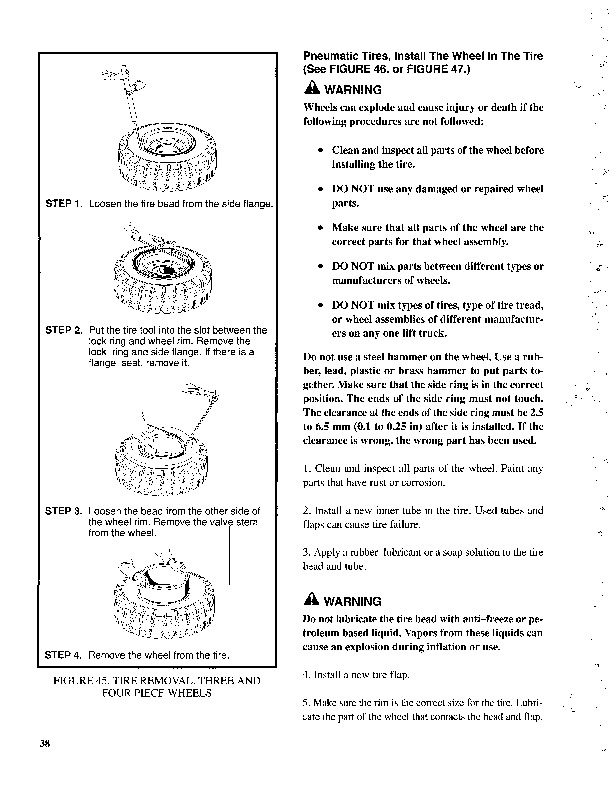
Wheel and Tire Replacement…424
Solid Rubber Tire, Change…424
Wheels, Install…425
SIT Tire, Change for S3.50-5.50XL (D004), and S6.00-7.00XL (B024…425
Remove SIT Solid Tire From Wheel…426
Install SIT Solid Tire on Wheel…427
Adhesives and Sealants…428
Hydraulic Oil, Lubricant, and Coolant Specifications…428
tables…367
Table 1. Maintenance Schedule…375
Table 2. Hook-Type Carriage Chain Adjustment…421
Transmission Repair…471
Remove…471
Disassemble…472
Transmission, Disassemble…472
Input Shaft, Disassemble…473
Reverse Clutch, Disassemble…475
Output Shaft (Pinion) and Differential, Remove and Disassemble…478
Clean and Inspect…480
Assemble…480
Input Shaft, Assemble…481
Reverse Clutch, Assemble…489
Output Shaft (Pinion) and Differential, Assemble and Install…494
Transmission, Assemble…501
Control Valve, Install…504
Install…504
Control Valve Repair…505
Remove, Early Model S3.50-5.50XL (S70-120XL) Lift Trucks…505
Disassemble, Early Model S3.50-5.50XL (S70-120XL) Lift Trucks…505
Assemble, Early Model S3.50-5.50XL (S70-120XL) Lift Trucks…506
Install, Early Model S3.50-5.50XL (S70-120XL) Lift Trucks…506
Remove and Disassemble, Later Model S3.50-5.50XL (S70-120XL) Tru…506
Inspect, Later Model S3.50-5.50XL (S70-120XL) Trucks and S3.50-5…509
Assemble and Install, Later Model S3.50-5.50XL (S70-120XL) Truck…509
MONOTROL® Pedal Repair…511
Remove and Disassemble, S3.50-5.50XL (S70-120XL) Model Lift Truc…511
Assemble and Install, S3.50-5.50XL (S70-120XL) Model Lift Trucks…512
Remove and Disassemble, S3.50-5.50XM (S70-120XM) Model Lift Truc…514
Assemble and Install, S3.50-5.50XM (S70-120XM) Model Lift Trucks…514
Direction Control Lever Repair…516
Remove and Disassemble…516
Assemble and Install…516
Stall Test…517
Linkages Adjustment…518
Linkage for Inching/Brake Pedal, S3.50-5.50XL (S70-120XL) (D004)…518
Linkage for Direction Control Lever…520
Linkage for Inching/Brake Pedal, S3.50-5.50XM (S70-120XM) (E004,…520
Brake Shoe Adjustment…520
Inching/Brake Pedal Height Adjustment…520
Single Pedal Height Adjustment…520
Two Pedal Height Adjustment…520
Inching/Brake Linkage Adjustment…522
Oil Pressures Check…524
System Pressure Check Port…524
Torque Converter Check Port…524
Clutch Pressure Check Port…525
Inching Pressure…525
Solenoid Check Ports ( MONOTROL Control Only)…527
Lubrication Pressure Check Ports…527
System Pressure Check Port…527
Torque Converter Check Port…527
Reverse Clutch Pressure Check Port…527
Forward Clutch Pressure Check Port…527
Lubrication Pressure Check Port…527
Modulator Pressure Check Port…527
Troubleshooting…528
tables…467
Table 1. Ring and Pinion Tooth Contact Adjustment…499
Table 2. Stall Speed Specifications…517
Table 3. Transmission Oil Pressure Check, Early Model S3.50-5.50…525
Table 4. Transmission Oil Pressure Check, Later Model S3.50-5.50…526
hyster-897322-09-03-srm0399…535
toc…535
Single-Speed Powershift Transmission…535
Safety Precautions Maintenance and Repair…536
General…539
Mechanical Description…539
General…539
Torque Converter…539
Oil Pump…539
Shaft Assemblies…539
Input Shaft…539
Reverse Clutch Shaft…539
Countershaft…540
Ring Gear, Pinion, and Differential…540
Clutch Assemblies…541
Hydraulic Operation…542
Torque Converter…542
Shaft Assemblies…543
Control Valve…543
General…543
System Regulator…543
Clutch Pressure Regulator…543
Torque Converter Regulator…543
Inching Spool…543
Direction Spool, Manual Control…545
Direction Spool, MONOTROL Pedal…545
Modulation Spool…545
Accumulator…545
Drain Spool…545
MONOTROL Pedal…545
Control Valve…547
General…547
Regulator for Clutch Pressure…547
Inching Spool Assembly…547
Direction Spool…550
Direction Spool, Manual Control…551
Modulator Circuit…551
Regulator for Torque Convertor…551
Lubrication Circuit…551
Direction Control Lever…551
MONOTROL Pedal…552
Start Circuit, MONOTROL Pedal…552
Creep Speed Switch…553
Oil Flow Diagrams…553
Neutral…553
Valves, Repair…849
Valve Seats, Repair…850
Valve Springs…851
Rocker Arm Studs (Early Models)…851
Rocker Arm Studs (Late Models)…852
Assemble and Install…852
Cylinder Block Cleaning and Inspection…856
Piston Bore Preparation…856
Engine Mounts Installation…856
Lubrication System Repair…857
Oil Pump, Remove and Disassemble…857
Clean and Inspect…857
Oil Pump, Assemble and Install…857
Oil Sump, Install…858
Timing Cover, Timing Sprockets, Camshaft, and Valve Lifters…859
Timing Cover…859
Remove…859
Install…861
Timing Sprockets…861
Remove…861
Install…861
Camshaft…862
Remove…862
Inspect…862
Install…862
Balance Shaft…863
Remove…863
Install…864
Hydraulic Valve Lifters…864
Remove…864
Disassemble…865
Clean and Inspect…865
Assemble…865
Install…866
Crankshaft Repair…867
Remove…867
Inspect and Repair…867
How to Check Clearance Between Main Bearings and Their Journals…868
Install…869
Piston and Connecting Rod Assemblies Repair…870
Connecting Rod Bearings, Replace…870
Piston and Connecting Rod Assemblies, Remove…871
Disassemble…871
Piston, Clean and Inspect…872
Cylinder Bores, Inspect and Repair…872
Piston Rings…873
Assemble…874
Piston and Connecting Rod Assemblies, Install…874
Flywheel and Flywheel Housing Repair…875
Flywheel, Repair…875
Flywheel, Install…875
H3.50-5.00XL (H70-110XL), S3.50-5.50XL (S70-120XL), S6.00-7.00XL…875
H6.00-7.00XL (H135-155XL)…875
Flywheel Housing H3.50-5.00XL (H70-110XL), H3.50-5.50XM (H70-120…875
Engine Adapter H6.00-7.00XL (H135-155XL)…875
Coolant Pump Repair…876
Thermostat Replacement…876
Fan Mount Repair (Early Models)…876
Fan Mount Assembly Repair (Late Models)…876
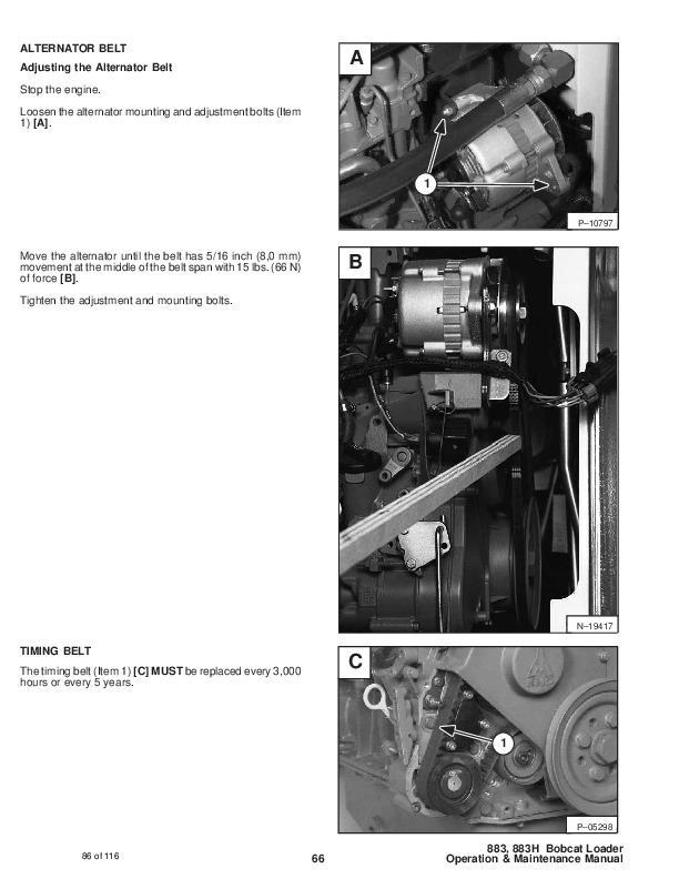
Drive Belt Installation…878
Valve Clearance Adjustment (Early Models)…879
Valve Clearance Adjustment (New Models)…880
Compression Check…880
Engine Specifications…880
Engine Data…880
Cylinder Head…881
Hydraulic Valve Lifter…881
Camshaft…881
Pistons…881
Crankshaft…882
Connecting Rods…883
Balance Shaft…883
Cooling System…883
Lubrication System…883
Torque Specifications…884
Troubleshooting…885
tables…843
Table 1. Piston Rings Arrangement on Piston…874
hyster-897934-11-01-srm0626…891
toc…891
Cooling System…891
Safety Precautions Maintenance and Repair…892
General…895
Description…896
Radiator…896
Radiator Cap…896
Thermostat…896
Water Pump…897
Fan and Fan Shroud…897
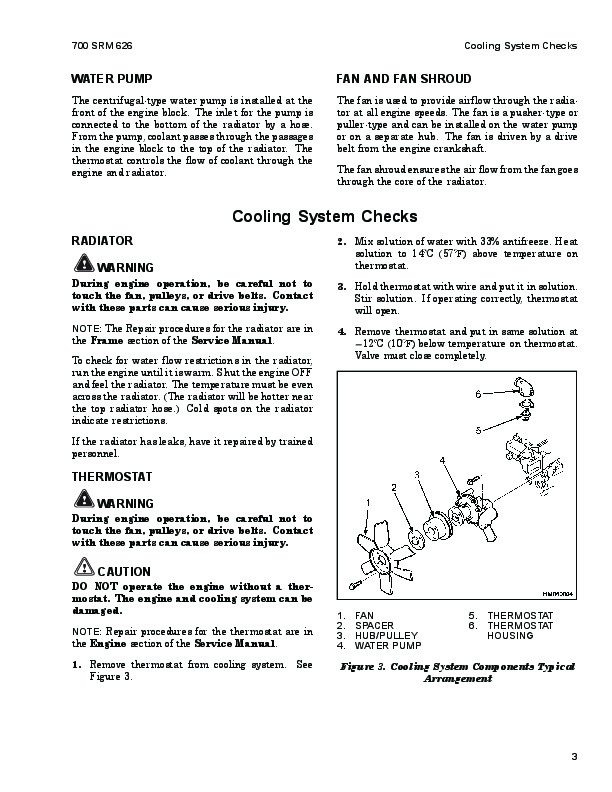
Cooling System Checks…897
Radiator…897
Thermostat…897
Water Pump…898
Exhaust Leaks…898
Fan and Fan Shroud…898
Radiator Cleaning…898
Drain…898
Clean…898
Fill…899
Motorola Alternators…941
Diodes Check…942
Diode Bridge Check…942
Delco and Leece-Neville Alternators…942
Motorola Alternators…942
Rotor Field Winding Check…943
Stator Windings Check…944
Voltage Regulator Check…944
Troubleshooting…944
hyster-899788-03-02-srm0107…949
toc…949
High Energy Ignition (HEI) System…949
Safety Precautions Maintenance and Repair…950
Description…953
Distributor Repair…955
Remove…955
Disassemble…955
Assemble…960
Install, If Crankshaft WAS NOT Rotated when Distributor was Remo…961
Install, If Crankshaft WAS Rotated when Distributor was Removed…961
Ignition Coil Replacement…962
Some Four- and Six-Cylinder Models…962
Remove…962
Install…963
V8, Some Four- and Six-Cylinder Models…963
Remove…963
Install…964
Electronic Module Replacement…965
Remove…965
Install…965
Sensing Coil Replacement…966
Remove…966
Install…966
Spark Plugs Replacement…966
Remove…966
Install…967
Visual Check…967
High Voltage Wires Check…967
Ignition Coil Check…968
Coil in Distributor Cap Design…968
Separate Coil Design…968
Sensing Coil, Check…969
Electronic Module Check…969
Ignition Timing Adjustment…969
GM V8-366 (6-liter) Ignition System Check…971
GM V6-LPG (4.3 liter) GM V6-LPG (4.3 liter) Ignition Timing and …971
Specifications…971
Troubleshooting…972
hyster-910076-10-03-srm0054…977
toc…977
Steering Control Unit…977
Safety Precautions Maintenance and Repair…978
General…981
Description…981
Operation…981
Steering Wheel and Column Assembly Repair…983
Steering Column Assembly Repair…983
Type A Steering Column Assembly…983
Remove and Disassemble…983
Assemble and Install…985
Type B Steering Column Assembly…987
Remove and Disassemble…987
Assemble and Install…987
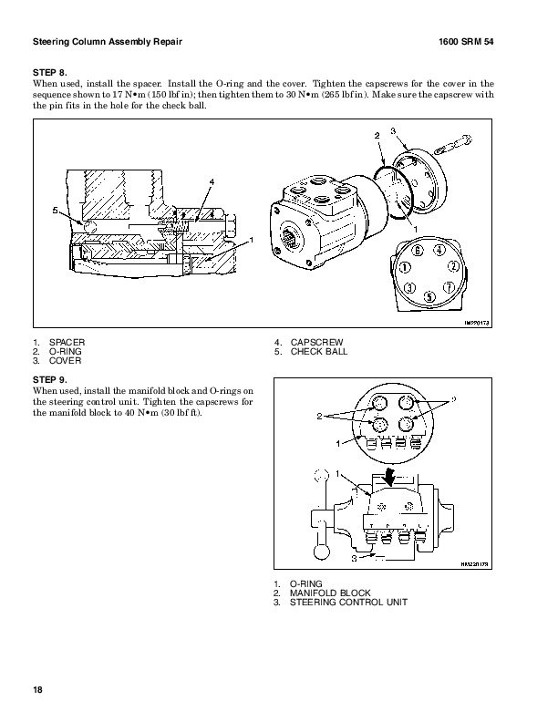
Steering Control Unit…990
Disassemble…990
Clean…993
Assemble…994
System Air Removal…999
Troubleshooting…999
hyster-910091-10-03-srm0097…1003
toc…1003
Hydraulic Gear Pumps…1003
Safety Precautions Maintenance and Repair…1004
Description…1007
Operation…1008
Flow Control Valve…1008
Relief Valve…1009
Hydraulic Gear Pump Repair…1009
Remove…1009
Disassemble…1010
Clean…1010
Inspect…1011
Assemble…1014
Install…1016
Pump Output Check…1016
Method No. 1…1016
Method No. 2…1017
Hydraulic System Air Check…1018
Troubleshooting…1019
hyster-910102-10-03-srm0103…1025
toc…1025
Tilt Cylinders…1025
Safety Precautions Maintenance and Repair…1026
General…1029
Description…1029
Tilt Cylinder Repair…1029
Remove…1029
Disassemble…1029
Clean…1029
Assemble…1030
Tilt Cylinders With O-Ring or Single-Lip Seals…1030
Tilt Cylinders for XM and XMS Models…1031
Tilt Cylinders for H700-800A and Early Model H700-920B…1032
Install…1033
Tilt Cylinders Using Chevron Packing…1034
Install…1035
Tilt Cylinder Leak Check…1037
Tilt Cylinder Stroke and Mast Tilt Angle Adjustment…1038
Torque Specifications…1039
Piston Rod Nut…1039
Retainer…1040
Troubleshooting…1042
tables…1025
Table 1. Movement Rates (Maximum) for Tilt Cylinders…1038
hyster-910107-02-01-srm0106…1045
toc…1045
Starter…1045
Safety Precautions Maintenance and Repair…1046
General…1049
Description and Operation…1049
Starter Repair…1051
Remove…1051
Disassemble…1051
Clean…1052
Assemble…1052
Install…1053
General Checks and Adjustments…1053
Troubleshooting…1056
hyster-910110-12-03-srm0143…1061
toc…1061
Instrument Panel Indicators and Senders…1061
Safety Precautions Maintenance and Repair…1062
General…1065
Description…1066
Steering Column Gauges, Meters, and Indicators…1066
LED Display Panel…1066
Battery Discharge Indicators…1066
Brush Wear Indicators…1073
Motor Temperature Indicators…1073
LX Series Display Panel…1075
Hourmeter Functions…1075
Battery Indicator Function…1076
Status Code Function…1077
ZX Series Display Panels…1077
Display Panel…1077
Basic Display Panels…1077
Performance Display…1080
Brush Wear Indicators…1083
Adjustments – General…1084
Replacement – General Information…1084
Meter Replacement…1085
Sender Replacement…1086
Fuel Level Sender…1086
Pressure and Temperature Sender…1086
ITW Display Panel Replacement…1087
Remove…1087
Column Mount Display Panel (EV-100/200ZX Motor Controllers) Repl…1088
Remove…1088
Display Panel Assembly, Replace…1088
Indicator LEDs…1089
Battery Indicators…1089
Digital Display (Performance Display Panel Only)…1089
Status Code or Performance Level Switches and Indicator LEDs (Pe…1089
Basic Display Panel, Replace Parts…1089
Performance Display Panel, Replace Parts…1091
Dash Mount Display Panel (EV100/200ZX Motor Controllers) Replace…1092
Remove and Replace…1092
Specifications…1092
Meter Specifications…1092
Sender Specifications…1093
Troubleshooting…1093
Meter…1093
hyster-910119-10-03-srm0135…1097
toc…1097
Lift Cylinders…1097
Safety Precautions Maintenance and Repair…1098
Safety Procedures When Working Near Mast…1101
General…1105
Description…1105
Lowering Control Valve…1105
Cylinders (General)…1108
Cylinders (H520-620B, H700-800A)…1108
Retainer, Install…1108
Cylinders (H360-460B)…1110
Cylinders (Two-Speed)…1112
Lift Cylinder Repair…1114
Lift Cylinder Removal Without Removing Mast…1114
Standard Masts With Main Lift Cylinder Fastened to Crossmember o…1114
Standard and Full Free-Lift Masts With Lift Cylinder Fastened to…1114
Masts That Have Two Cylinders, Main Lift Cylinder and Free-Lift …1114
Disassemble…1116
Assemble…1116
Lift Cylinder Installation in Mast…1118
Standard Masts With Main Lift Cylinder Fastened to Crossmember o…1118
Standard and Full Free-Lift Masts With Lift Cylinder Fastened to…1118
Chevron-Style Packing…1118
Chevron-Style Packing Installation on Piston…1119
Chevron-Style Packing Installation in Packing Gland…1121
Lift Cylinders for VISTA® Masts…1122
Description…1122
Lowering Control Valve…1122
Remove…1124
Disassemble…1125
Assemble…1126
Install…1127
Main Lift Cylinders…1127
Free-Lift Cylinder…1127
Lift System Leak Check…1128
Specifications…1129
Troubleshooting…1130
tables…1097
Table 1. Lift Trucks with Two-Speed Lift Cylinders…1113
Table 2. Cylinder Retainer Torque Specifications and Weight Guid…1129
hyster-910442-03-03-srm0231…1133
toc…1133
Metric and Inch (SAE) Fasteners…1133
Safety Precautions Maintenance and Repair…1134
General…1137
Threaded Fasteners…1137
Nomenclature, Threads…1137
Strength Identification…1138
Cotter (Split) Pins…1138
Fastener Torque Tables…1143
Conversion Table…1145
tables…1133
Table 1. Bolts and Screws…1139
Table 2. Studs and Nuts…1140
Table 3. Torque Nuts…1141
Table 4. Torque Nuts With Nylon Insert…1142
Table 5. Torque Values for Metric Fasteners*…1143
Table 6. Torque Values for Inch Fasteners*…1144

Hyster S70-120XL (D004) Repair Service Manual


INSTANT DOWNLOAD


Posted on

Hyster H135-155XL (F006) Repair Service Manual


INSTANT DOWNLOAD


Complete service repair manual for Hyster H135-155XL, with all the technical information to maintain, diagnose, repair, and rebuild like professional mechanics.

Hyster H135XL-H155XL workshop service & repair manual includes:
* Numbered table of contents easy to use so that you can find the information you need fast.
* Detailed sub-steps expand on repair procedure information
* Numbered instructions guide you through every repair procedure step by step.
* Troubleshooting and electrical service procedures are combined with detailed wiring diagrams for ease of use.
* Notes, cautions and warnings throughout each chapter pinpoint critical information.
* Bold figure number help you quickly match illustrations with instructions.
* Detailed illustrations, drawings and photos guide you through every procedure.
* Enlarged inset helps you identify and examine parts in detail.

897137 – Hyster Service Manual H135-155XL (F006).pdf

Total Pages: 1,453 pages
File Format: PDF (Internal Links, Bookmarked, Table of Contents, Searchable, Printable, high quality)
Language: English

Section Part No. SRM Number Rev Date
FRAME 897104 0100 SRM 0322 11/03
GM V6-4.3L ENGINE (CARBURETED) 599805 0600 SRM 0104 09/93
PERKINS ENGINES 4.236, 4.2482 910150 0600 SRM 0105 06/97
PERKINS DIESEL ENGINE-1000 SERIES 897341 0600 SRM 0412 08/97
GM V6-4.3L ENGINE WITH FUEL INJECTION 897800 0600 SRM 0590 11/03
PERKINS DIESEL ENGINE-1000 SERIES (AR, YG, YH) 1455747 0600 SRM 0705 09/03
COOLING SYSTEM 897934 0700 SRM 0626 11/01
WEBER CARBURETOR WITH GOVERNOR 897128 0900 SRM 0347 12/92
LPG FUEL SYSTEM 897129 0900 SRM 0348 09/01
MANUAL TRANSMISSION AND OIL CLUTCH 910233 1300 SRM 0061 02/97
TWO-SPEED PS TRANS-DESCR / OPER 897106 1300 SRM 0324 10/03
TWO-SPEED PS TRANSMISSION-REPAIR 897107 1300 SRM 0325 10/03
SPEED REDUCER 897125 1300 SRM 0344 03/97
DIFFERENTIAL 910072 1400 SRM 0046 11/03
DRIVE AXLE 910073 1400 SRM 0049 09/03
STEERING CONTROL UNIT 910076 1600 SRM 0054 10/03
STEERING AXLE 897108 1600 SRM 0326 10/03
BRAKE SYSTEM 897109 1800 SRM 0327 09/03
HYDRAULIC GEAR PUMPS 910091 1900 SRM 0097 10/03
‘HYDRAULIC VANE PUMPS 910092 1900 SRM 0098 07/03
HYDRAULIC SYSTEM 897110 1900 SRM 0328 09/03
MAIN CONTROL VALVE 899783 2000 SRM 0090 10/03
TILT CYLINDERS 910102 2100 SRM 0103 10/03
ALTERNATOR 899784 2200 SRM 0002 10/03
STARTER 910107 2200 SRM 0106 02/01
HIGH ENERGY IGNITION SYSTEM 899788 2200 SRM 0107 03/02
INSTRUMENT PANEL INDICATORS / SENDERS 910110 2200 SRM 0143 12/03
MSTS-GM V6-4.3L (EARLY CONTROL MODULES) 897412 2200 SRM 0463 04/93
MSTS-GM V6-4.3L (LATER CONTROL MODULES) 1473385 2200 SRM 0765 11/01
GM V6 ENG CONTROL-DESC/OPER (EARLY MODULES) 897435 2200 SRM 0473 03/94
GM V6 ENGINE CONTROL-REPAIR (EARLY MODULES) 897420 2200 SRM 0468 05/96
GM V6 ENG CONTROL-DESC/OPER (LATER MODULES) 1474823 2200 SRM 0781 01/00
GM V6 ENGINE CONTROL-REPAIR (LATER MODULES) 1474824 2200 SRM 0782 03/00
LIFT CYLINDERS 910119 4000 SRM 0135 10/03
MASTS 897111 4000 SRM 0329 10/03
METRIC AND INCH (SAE) FASTENERS 910442 8000 SRM 0231 03/03
CAPACITIES and SPECIFICATIONS 897113 8000 SRM 0331 09/03
DIAGRAMS 897114 8000 SRM 0332 03/03
PERIODIC MAINTENANCE 897123 8000 SRM 0341 12/03
DIAGRAMS-GM ELECTRONIC ENGINE CONTROL 897501 8000 SRM 0519 12/03
 
PART NO. 897137         Rev. 12/03

    Perkins Diesel Engines..3
    Safety Precautions Maintenance and Repair..4
    General..11
      General Safety Rules..11
    Description..12
      Engine Serial Number Codes..15
      Engine Data..15
    Engine Removal and Installation..17
      Lift Engine..17
    Cylinder Head Assembly Repair..17
      Valve Cover..17
        Remove..17
        Install..18
      Rocker Arm Assembly..18
        Remove..18
        Install..18
        Disassemble..18
        Inspect..18
        Assemble..19
      Valve Clearance Adjustments..19
        Four-Cylinder Engines..20
        Six-Cylinder Engines..20
      Valve Springs..20
      Cylinder Head Assembly..22
        Remove..22
        Install..24
      Valves and Valve Springs..28
        Remove..28
        Inspect..28
        Install..29
      Valve Guides..29
        Inspect..29
        Remove..30
        Install..30
      Cylinder Head and Valve Seats..30
        Inspect..30
        Repair..30
        New Valve Seats, Install..30
    Piston and Connecting Rod Assemblies Repair..32
      Rod Bearings..32
        Remove..33
        Install..33
      Piston and Connecting Rod Assembly..34
        Service Note..34
        Remove..34
        Install..35
      Piston Rings..36
        Remove..36
        Inspect..36
        Install..36
      Piston and Connecting Rod..37
        Disassemble..37
        Inspect..38
        How to Select Correct Replacements..38
        Install..39
      Piston Cooling Jets..39
        Remove..39
        Install..40
    Crankshaft Assembly Repair..40
      General..40
      Crankshaft Pulley..41
        Engine AR, Remove..41
        Engines YG and YH, Remove..41
        Inspect..42
        Engine AR, Install..42
        Engines YG and YH, Install..42
      Rear Oil Seal..43
        Replace..43
      Main Bearings..44
        Remove..44
        Inspect..45
        Install..45
      Thrust Washers..45
        Crankshaft Axial Movement, Check..45
        Remove..46
        Install..46
      Crankshaft..47
        Remove..47
        Inspect..47
        Install..47
      Flywheel..49
        Remove..49
        Ring Gear, Replace..49
        Install..49
      Flywheel Housing..50
        Remove..50
        Install..50
    Timing Case and Timing Gears Repair..51
      General..51
      Timing Case Cover..51
        Remove..51
        Install..52
      Front Oil Seal..52
        Remove..52
        Install..52
      Crankshaft Pulley Wear Sleeve..53
        Install..53
      Idler Gear and Hub..53
        Remove..53
        Install..54
      Air Compressor Drive, Bendix..55
        Disassemble..55
        Assemble..56
      Fuel Injection Pump Gear..56
        Remove..57
        Install..57
      Camshaft Gear..58
        Remove..58
        Install..58
      Crankshaft Gear..59
        Remove..59
        Install..59
      Timing Case..59
        Remove..59
        Install..60
      Camshaft and Tappets..61
        Remove..61
        Install..61
    Cylinder Block Assembly Repair..62
      Description..62
      Cylinder Block..62
        Disassemble..62
        Inspect..63
        Assemble..63
      Cylinder Bore (Four-Cylinder Engines)..64
      Cylinder Liner (Six-Cylinder Engines)..64
        Inspect..64
        Cylinder Liner Condition, Check..64
        Remove..65
        Service Liner, Install..66
        Partially Finished Liner, Install..67
    Engine Timing..68
      Description..68
        How to Set Number One Piston to TDC on Compression Stroke..69
        How to Set Number One Piston to TDC on Compression Stroke (Alter..70
        Valve Timing, Check..70
        Fuel Injection Pump Timing, Check..71
    Turbocharger – Engine YH Repair..72
      General..72
        Remove..72
        Install..72
        Impeller and Compressor Housing, Clean..73
    Lubrication System Repair..74
      General..74
      Oil Filter, Replace..74
      Filter Head..75
        Remove and Install..75
      Oil Sump..75
        Remove..75
        Install..76
      Oil Pump..76
        Remove..76
        Inspect..76
        Install..77
      Relief Valve..77
        Remove..77
        Disassemble..78
        Inspect..78
        Assemble..78
        Install..78
      Idler Gear Shaft, Replace..79
        Remove..79
        Remove (Alternative)..79
        Install..80
        Install (Alternative)..80
        Install (Alternative for Four-Cylinder Engines Only)..81
    Fuel System Repair..81
      Description..81
      Fuel Injection Pump..82
        Remove..82
        Install..83
        Check and Adjust..84
      Fuel System, Remove Air..84
      Fuel Filter, Replace..85
        Canister Type..86
        Quick Release Canister Type..86
      Fuel Injectors..87
        Remove..87
        Inspect..88
        Install..88
      Fuel Pump..89
        Remove..89
        Disassemble..89
        Assemble..89
        Install..90
        Test..90
    Cooling System Repair..91
      General..91
      Thermostat..91
        Remove..91
        Install..91
        Test..92
      Coolant Pump..92
        Remove..92
        Disassemble..92
        Assemble..94
        Install..96
      Fan and Fan Drive..97
        Remove..97
        Install..97
      Oil Cooler (Six-Cylinder Engines)..98
        Remove..98
        Disassemble and Assemble..98
        Install..98
        Oil Cooler By-Pass Valve..98
    Electrical Equipment Repair..99
      Drive Belts..99
      Alternator..100
        Remove..100
        Install..100
      Starter Motor..100
        Remove..100
        Install..100
      Cold Start Aid..100
    Air Compressor – Engines YG and YH..100
      General..100
      Repair..101
        Remove..101
        Install..101
    Rotary Exhauster Replacement..102
      Remove..102
      Clean..102
      Install..102
    Engine Specifications..103
      Cylinder Head Assembly..103
      Piston and Connecting Rods..106
      Crankshaft Assembly..109
        Crankshaft Overhaul..110
      Timing Case and Drive Assembly..112
      Engine Block Assembly..113
      Turbocharger..116
      Lubrication System..116
      Fuel System..118
      Cooling System..120
      Flywheel and Housing..120
      Electrical Equipment..121
    Torque Specifications..122
      Cylinder Head Assembly..122
      Piston and Connecting Rod Assemblies..122
      Crankshaft Assembly..122
      Timing Case and Drive Assembly..122
      Turbocharger..122
      Lubrication System..122
      Fuel System..122
      Cooling System..123
      Flywheel..123
      Auxiliary Equipment..123
    Special Torque Specifications..124
      Flywheel and Housing..124
      Turbocharger..124
      Electrical Equipment..124
      Auxiliary Equipment..124
    Special Tools..125
    Troubleshooting..129
  tables..3
    Table 1. Cylinder Head..103
    Table 2. Valve Guides..103
    Table 3. Inlet Valves..104
    Table 4. Exhaust Valves..105
    Table 5. Valve Springs..106
    Table 6. Tappets..106
    Table 7. Rocker Arm Shaft..106
    Table 8. Rocker Arms and Bushings..106
    Table 9. Pistons (Engine AR)..106
    Table 10. Pistons (Engines YG and YH)..107
    Table 11. Piston Rings (Engine AR)..107
    Table 12. Piston Rings (Engines YG and YH)..108
    Table 13. Piston Pins..108
    Table 14. Connecting Rods..108
    Table 15. Small End Bushings..108
    Table 16. Connecting Rod Bearings (Engines AR and YG)..109
    Table 17. Connecting Rod Bearings (Engine YH)..109
    Table 18. Piston Cooling Jets..109
    Table 19. Crankshaft..109
    Table 20. Main Bearings..110
    Table 21. Crankshaft Thrust Washers..110
    Table 22. Crankshaft Heat Treatment..110
    Table 23. Crankshaft Overhaul Specifications..111
    Table 24. Maximum Variation (Run-out)..112
    Table 25. Camshaft..112
    Table 26. Camshaft Thrust Washer..112
    Table 27. Camshaft Gear..113
    Table 28. Gear for Fuel Injection Pump..113
    Table 29. Crankshaft Gear..113
    Table 30. Idler Gear and Hub..113
    Table 31. Cylinder Block (Engine AR)..114
    Table 32. Cylinder Bore Specifications..114
    Table 33. Cylinder Block (Engines YG and YH)..115
    Table 34. Cylinder Liners (Engines YG and YH)..115
    Table 35. Cylinder Liner Specifications (Partially Finished)..116
    Table 36. Oil Pump (Engine AR)..116
    Table 37. Oil Pump (Engines YG and YH)..117
    Table 38. Idler Gear for Oil Pump..117
    Table 39. Relief Valve..117
    Table 40. Oil Filter..117
    Table 41. Lucas Fuel Injection Pump..118
    Table 42. Fuel Pump (Engine AR)..118
    Table 43. Fuel Pump (Engines YG and YH)..118
    Table 44. Fuel Filter..118
    Table 45. Fuel Injector Codes..119
    Table 46. Coolant Pump..120
    Table 47. Thermostat..120
    Table 48. Fan Drive Housing..120
    Table 49. Limits for Flywheel Run Out and Alignment (Total Indic..120
    Table 50. Alternator..121
    Table 51. Starter Motor..121
    Table 52. Cold Start Aid..121
    Table 53. List of Possible Causes..130
hyster-1473385-11-01-srm0765..135
hyster-1474823-01-00-srm0781..183
hyster-897104-11-03-srm0322..335
  toc..335
    Frame..335
    Safety Precautions Maintenance and Repair..336
    General..339
    Description..339
    Counterweight Repair..340
      Remove..340
      Install..340
    Hood Repair..341
      Remove..341
      Install..341
    Overhead Guard Repair..341
      Remove..341
      Install..341
    Operator Restraint System Repair..342
    Hydraulic Tank Repair..343
      Remove..343
      Inspect..343
      Small Leaks Repair..343
      Large Leaks Repair..343
      Clean..343
        Steam Method..344
        Chemical Solution Method..344
      Other Methods of Preparation for Repair..344
      Install..344
    Fuel Tank Repair..345
      Remove..345
      Repair..345
      Install..345
    Radiator Repair..345
      Remove..345
      Install..345
    Engine Repair..346
      Remove..346
      Install..346
    Safety Labels..348
    Cab Repair..350
      Cab, Replace..350
      Window, Replace..350
      Windshield Wipers and Heater..350
  tables..335
    Table 1. Material Specifications for Cab Windows..352
hyster-897106-10-03-srm0324..355
  toc..355
    Two-Speed Powershift Transmission..355
    Safety Precautions Maintenance and Repair..356
    General..359
    Mechanical Description..359
      Torque Converter..359
      Transmission Pump..360
      Shaft Assemblies..360
      Input Shaft..361
      Forward Clutch Shaft..361
      Clutch Assemblies..361
      Countershaft..368
      Output Shaft..368
    Hydraulic Operation..369
      Torque Converter..369
      Seal Rings..370
    Control Valve..370
      System Pressure Regulator..373
      Clutch Pressure Regulator..373
      Torque Converter Regulator..374
      Inching Spool..374
      Direction Spool, Direction Control Lever..374
      Direction Spool, MONOTROL Pedal..375
      Range Spool..375
      Drain Spool..376
      Accumulator..376
      Modulator Spool..376
      Operation..376
    Lubrication Circuit..377
    MONOTROL Pedal..377
    Oil Flow Diagrams..379
      Neutral..379
      Forward-Low..380
      Forward-Low-Inching..381
      Reverse-Low..382
hyster-897107-10-03-srm0325..385
  toc..385
    Two-Speed Powershift Transmission..385
    Safety Precautions Maintenance and Repair..386
    General..389
    Transmission Repair..389
      Transmission and Torque Converter, Remove..389
      Transmission, Disassemble..391
      Reverse-Low Clutch, Disassemble..394
      Reverse-High Clutch, Disassemble..397
      Forward-Low Clutch, Disassemble..400
      Forward-High Clutch, Disassemble..403
      Clean and Inspect..405
    Forward Low and High Clutches Assembly..406
      Forward Clutches, Assemble..408
      Reverse-Low Clutch, Assemble..414
      Reverse Clutches, Assemble..416
      Transmission, Assemble..423
      Torque Converter, Install..430
    Control Valve Repair..431
      Remove..431
      Disassemble..432
      Assemble..433
      Install..435
    MONOTROL Pedal..435
      Remove and Disassemble..435
      Assemble and Install..435
    Stall Test..438
    Linkage Adjustments..439
      Linkage for Inching Pedal H6.00-7.00XL (H135-155XL, H135-155XL 2..439
      Linkage for Inching Pedal S6.00-7.00XL (S135-155XL, S135-155XL 2..442
      Linkage for Range Lever – Early Model H6.00-7.00XL (H135-155XL) ..445
      Linkage for Direction Control Lever – Early Model H6.00-7.00XL (..445
      Linkage for Range Lever – Later Model H6.00-7.00XL (H135-155XL, ..447
      Linkage for Direction Control Lever – Later Model H6.00-7.00XL (..449
      Linkage for Range Lever S6.00-7.00XL (S135-155XL, S135-155XL 2 )..451
      Linkage for Direction Control Lever S6.00-7.00XL (S135-155XL, S1..451
    Oil Pressure Check..453
      System Pressure Check Port..453
      Torque Converter Check Port..453
      Clutch Pressure Check Port..453
      Inching Pressure..454
      Solenoid Check Ports (MONOTROL Control Only)..454
      Lubrication Pressure Check Ports..454
    Specifications..455
    Troubleshooting..455
      Correct System Pressure: 1300 ±124 kPa ( 189 ±18 psi)..458
      Correct Clutch Pressure: 924 ±69 kPa ( 134 ±10 psi)..459
      Correct Solenoid Pressure (MONOTROL Only): 965 ±138 kPa ( 140 ±2..460
      Torque Converter Pressure: 834 ±69 kPa ( 121 ±10 psi)..460
      Lubrication Pressure: 83 ±21 kPa ( 12 ±3 psi)..460
  tables..385
    Table 1. Stall Speed Specifications..438
hyster-897108-10-03-srm0326..463
  toc..463
    Steering Axle..463
    Safety Precautions Maintenance and Repair..464
    General..467
    Description..467
    Steering Axle Assembly Repair..471
      Steering Axle H3.50-5.00XL (H70-110XL) (G005), S3.50-5.50XL (S70..471
        Remove..471
        Install..472
      Steering Axle H6.00-7.00XL (H135-155XL, H135-155XL 2 ) (F006, G0..472
        Remove..472
        Install..473
    Wheels and Hubs Repair (All Units)..473
      Remove and Disassemble..473
      Clean..473
      Inspect..473
      Assemble and Install..474
    Spindles and Bearings Repair (All Units)..475
      Remove..475
      Clean..475
      Assemble and Install..475
    Tie Rods Repair (All Units)..476
      Remove..476
      Clean..476
      Install..476
    Steering Cylinder Repair..479
      Remove and Disassemble..479
      Clean and Inspect..479
      Assemble and Install..479
    Troubleshooting..480
hyster-897109-09-03-srm0327..485
  toc..485
    Brake System..485
    Safety Precautions Maintenance and Repair..486
    General..489
    Description..489
    Operation..490
      Brake Booster and Master Cylinder..490
        Brake Booster..490
        Master Cylinder..491
      Service Brake Assembly..492
      Parking Brake..493
    Brake Shoe Assemblies Repair..494
      Remove and Disassemble..494
      Clean and Inspect..495
        Cleaning Procedures..495
        Inspect..495
      Assemble and Install..496
    Master Cylinder Repair..497
      Remove..497
      Disassemble..497
      Assemble..499
      Install..499
    Brake Booster Repair..499
      Remove..499
      Disassemble..499
      Clean and Inspect..501
      Assemble..501
      Install..501
    Brake System Air Removal..501
    Brake Pedal Adjustment..502
    Brake Shoes Adjustment..503
    Parking Brake Adjustment..503
    Parking Brake Switch Adjustment..503
    Brake Booster Relief Valve Check..503
    Troubleshooting..504
hyster-897110-09-03-srm0328..509
  toc..509
    Hydraulic System..509
    Safety Precautions Maintenance and Repair..510
    General..513
    Description and Operation..513
      Hydraulic Pumps..515
      Main Control Valve..515
      Control Valve Lever..516
      Steering Control Unit..516
      Brake Valve..516
      Oil Clutch, H6.00-7.00XL (H135-155XL) (F006)..517
    Troubleshooting..517
      Lift, Lower, and Tilt Circuit..518
      Steering, Brake, and Oil Clutch System..519
hyster-897111-10-03-srm0329..523
  toc..523
    Masts..523
    Safety Precautions Maintenance and Repair..524
    General..527
    Description and Operation..527
      General..527
      Safety Procedures When Working Near Mast..528
      Two-Stage Mast..528
      Three-Stage Mast..530
    Carriage Repair..532
      Remove..532
      Sideshift Carriage, Disassemble..532
      Sideshift Carriage, Assemble..533
      Install..533
    Two-Stage Mast Repair..535
      Remove..535
      Disassemble..536
      Clean and Inspect..537
      Assemble..538
      Install..538
    Three-Stage Mast Repair..540
      Remove..540
      Disassemble..540
      Clean and Inspect..540
      Assemble..540
      Install..542
    Mast Operation Check..542
    Lift and Tilt System Leaks Check..543
      Lift System..543
      Tilt System..543
    Tilt Cylinder Stroke and Backward Tilt Angle Adjustment..544
    Lift Chain Adjustments..544
    Mast Adjustments..547
    Carriage Adjustment..547
    Troubleshooting..549
  tables..523
    Table 1. Mast Parts Weight..536
    Table 2. Hook-Type Carriage Chain Adjustment..545
    Table 3. Pin-Type Carriage Chain Adjustment..545
hyster-897113-09-03-srm0331..553
  toc..553
    Capacities and Specifications..553
    Safety Precautions Maintenance and Repair..554
    Lift Truck Weights..557
    Capacities..557
    Tire Sizes..558
    Tire Pressure..558
    Electrical System..558
    Wheel Nut Torque..558
    Engine Specifications..559
    Hydraulic System..559
    Mast Speeds..560
    Transmission Oil Pressures..560
    Torque Specifications..561
      Engine – GM 4.3L V-6..561
      Engine – Perkins 4.2482..561
      Engine – Perkins 1004.4..561
      Clutch..561
      Manual Transmission..562
      Powershift Transmission..562
      Speed Reducer..562
      Drive Axle..562
      Steering System..562
      Brake System..562
      Hydraulic System..563
      Tilt Cylinder..563
      Mast..563
hyster-897114-03-03-srm0332..567
  toc..567
    Diagrams..567
    Safety Precautions Maintenance and Repair..568
hyster-897123-12-03-srm0341..591
  toc..591
    Periodic Maintenance..591
    Safety Precautions Maintenance and Repair..592
    General..597
      Serial Number Data..597
      How to Move Disabled Truck..597
        How to Tow Lift Truck..597
      How to Put Lift Truck on Blocks..598
        How to Raise Drive Tires..598
        How to Raise Steering Tires..598
    Maintenance Schedule..599
    Maintenance Procedures Every 8 Hours or Daily..615
      How to Make Checks With Engine Stopped..615
        Hydraulic System Oil..616
        Engine Oil..616
        Drive Belts..617
        Intake Manifold Rubber Cap..617
        Cooling System..617
        Air Filter..618
        Fuel System..618
        Primary Fuel Filter, Diesel Engine..619
        Battery..619
        Tires and Wheels..619
        Forks..620
          Adjust..620
          Remove and Install..620
        Forks, Mast, and Lift Chains, Inspect..623
        Operator Restraint System..624
        Safety Labels..625
      How to Make Checks With Engine Running..625
        Gauges, Lights, Horn, and Fuses..625
        Oil Level, Powershift Transmission..627
        Oil Level, Oil Clutch System, H3.50-5.00XL (H70-110XL)..627
        Control Levers and Pedals..627
        Lift System Operation..627
        Inching/Brake Pedal..628
        Service Brakes..628
        Parking Brake..628
        Steering System..628
    Maintenance Procedures Every 250 Hours or 6 Weeks..629
      Engine Oil and Filter, GM V-6 Engine..629
      Lift Chains, Lubrication..629
      Drive Shafts..629
      Mast Lubrication..630
      Crankcase Breather, GM V-6..630
      Air Filter, GM V-6 EPA Compliant Engine ..630
    Maintenance Procedures Every 350 Hours or 2 Months..631
      Engine Oil and Filter, Perkins 4.2482 Diesel Engine..631
      Drive Belts..631
        Perkins Diesel Engine..631
        GM V-6 Engine (Early Models)..632
        GM V-6 Engine (Late Models)..632
      Brake Fluid..634
      Lift Chains Wear Check..634
      Forks Wear and Damage Check..635
      Steering Axle Lubrication..635
      Fuel System, Checks and Adjustments..635
        Diesel Fuel System..635
        LPG Carburetor (Early Models)..635
        Gasoline Carburetor (Early Models)..636
        Fuel Injection (Late Models)..636
      Crankcase Breather, Perkins 4.2482 Diesel Engine..636
      Hydraulic Tank Breather..636
      Cooling System, Clean Debris from Radiator Core..636
    Maintenance Procedures Every 500 Hours or 3 Months..637
      Engine Oil and Filter, Perkins Diesel Engine..637
      Crankcase Breather, Perkins Diesel Engine..637
      PCV Valve, GM V-6..637
    Maintenance Procedures Every 1000 Hours or 6 Months..638
      Manifold Heat Valve, GM V-6 (Early Models)..638
      Ignition System, GM V-6..638
      Valve Clearance Adjustment..638
      Fuel Filter, Replace (Diesel Engine)..638
      Fuel System Air Removal (Perkins 1004-4 Diesel Engine)..638
        Fuel Injection Pump With Vent Tube..639
        Fuel Injection Pump With Vent Screw..639
      Fuel System Air Removal (Perkins 4.2482 Diesel Engine)..641
      Oil Level Check in Transmission..641
        Manual Transmission, H3.50-5.00XL (H70-110XL)..641
        Speed Reducer for Powershift Transmission, H3.50-5.00XL (H70-110..641
        Manual Transmission, H6.00-7.00XL (H135-155XL)..641
        Differential and Drive Axle for Powershift Transmission, H6.00-7..641
        Differential, Speed Reducer, and Drive Axle for Manual Transmiss..642
      Control Levers and Pedals, Lubricate..642
      Crankcase Breather, Replace..642
      Cooling System, GM V-6 EPA Compliant Engine..642
      Spark Plug Replacement..642
        Remove..642
        Install..643
      LPG Fuel Filter GM V-6 EPA Compliant Engine, Replace..643
      Inspect Engine Electrical System, Connectors, and FCVS Connectio..644
    Maintenance Procedures Every 2000 Hours or Yearly..644
      Hydraulic System..644
        Hydraulic Oil and Filter, H3.50-5.00XL (H70-110XL), Replace..644
        Hydraulic Oil and Filter, H6.00-7.00XL (H135-155XL, H135-155XL 2..645
      Oil Change and Oil Filter Replacement, Powershift Transmission, ..645
      Oil Change, Manual Transmission, H3.50-5.00XL (H70-110XL)..645
      Oil Change, Manual Transmission, H6.00-7.00XL (H135-155XL)..645
      Oil Change, Speed Reducer, Powershift Transmission, H3.50-5.00XL..645
      Oil and Filter Change, Oil Clutch System, H3.50-5.00XL (H70-110X..646
      Oil Change, Differential and Drive Axle, Powershift Transmission..646
      Oil Change, Differential, Speed Reducer, and Drive Axle, Manual ..646
      Cooling System..646
      PCV Valve, GM V-6..646
      Service Brakes..647
      LPG Filter, Replace..647
      Gasoline Fuel Filter, Replace..648
      Hood Latch Check, H3.50-5.00XL (H70-110XL)..648
      Air Filter Element, GM V-6 EPA Compliant Engine..648
      Oxygen Sensor GM V-6 EPA Compliant Engine..648
      Inspect Low Pressure Regulator (LPR) for Oil Buildup and Leaks..649
      Check Throttle Shaft for Sticking..650
      Inspect Exhaust Manifold and Piping for Leaks..650
      Test LPG/GAS Regulator Pressure..650
    Safety Procedures When Working Near Mast..650
    Lift Chain Adjustments..652
    Fuel Injectors Repair..654
    Lift and Tilt System Leak Check..654
      Lift Cylinders, Leak Check..654
      Tilt Cylinders, Leak Check..655
    Welding Repairs..655
    Overhead Guard Changes..656
    Wheel and Tire Replacement..657
      Remove Wheels From Lift Truck..657
      Remove Wheels From Tire..657
        Remove Tire From Two-Piece Wheel..658
        Remove Tire From Three- and Four-Piece Wheels..660
      Install Wheel in Tire..661
        Install Three- or Four-Piece Wheel in Tire..662
        Install Two-Piece Wheel in Tire..663
      Add Air to Pneumatic Tires..664
      Wheels, Install..664
    Solid Rubber Tires Repair..665
      Wheel, Tire Remove..665
      Wheel, Tire Install..667
      SIT Tire, Change for H3.50-5.00XL (G005), and H6.00-7.00XL (F006..668
        Remove SIT Solid Tire From Wheel..669
        Install SIT Solid Tire on Wheel..670
    Adhesives and Sealants..671
    Hydraulic Oil, Lubricant, and Coolant Specifications..672
  tables..591
    Table 1. Maintenance Schedule..601
    Table 2. Hook-Type Carriage Chain Adjustment..653
    Table 3. Pin-Type Carriage Chain Adjustment..653
hyster-897129-09-01-srm0348..699
  toc..699
    LPG Fuel System..699
    Safety Precautions Maintenance and Repair..700
    General..703
    Description and Operation..705
      Fuel Tank..705
      Fuel Filter and Fuel Valve Unit..706
      Vaporizer..707
      Carburetor..708
      Governor..710
    LPG Tank Repair..711
      Remove..711
        LPG Tanks with Fixed Mounting Bracket..711
        LPG Tanks with EZ Lift Mounting Bracket..711
      Install..712
        LPG Tanks with Fixed Mounting Bracket..712
        LPG Tanks with EZ Lift Mounting Bracket..713
    Hydrostatic Relief Valve Repair..714
      Remove and Install..714
    Filter Unit Repair..714
      Fuel Filter Element, Replace..714
      Diaphragm and Fuel Valve, Replace..714
    Hoses Replacement..716
    Vaporizer Repair..716
      Remove..716
      Disassemble..716
      Clean..716
      Inspect..716
      Assemble..718
      Install..722
    Carburetor Repair..722
      Remove..722
      Disassemble..722
      Clean..722
      Assemble..722
      Install..722
    Governor Repair..724
    Filter Unit Check..726
    Vaporizer Check..726
      Pressure Reducer Valve..726
      Vapor Valve..726
    Carburetor Adjustment..726
      Idle Mixture..726
      Idle Speed..726
      Power Mixture..727
    Throttle Linkage Adjustment..727
    Troubleshooting..729
    Diagrams..949
    Safety Precautions Maintenance and Repair..950
hyster-897800-11-03-srm0590..1013
  toc..1013
    GM Engines..1013
    Safety Precautions Maintenance and Repair..1014
    General..1017
    Description..1017
    Engine Removal and Installation..1018
    Cylinder Head Repair..1018
      Remove and Disassemble..1018
      Clean and Inspect..1018
      Valve Guides and Seats, Repairs..1019
      Valves, Repair..1019
      Valve Seats, Repair..1020
      Valve Springs..1021
      Rocker Arm Studs (Early Models)..1021
      Rocker Arm Studs (Late Models)..1022
      Assemble and Install..1022
    Cylinder Block Cleaning and Inspection..1026
    Piston Bore Preparation..1026
    Engine Mounts Installation..1026
    Lubrication System Repair..1027
      Oil Pump, Remove and Disassemble..1027
      Clean and Inspect..1027
      Oil Pump, Assemble and Install..1027
      Oil Sump, Install..1028
    Timing Cover, Timing Sprockets, Camshaft, and Valve Lifters..1029
      Timing Cover..1029
        Remove..1029
        Install..1031
      Timing Sprockets..1031
        Remove..1031
        Install..1031
      Camshaft..1032
        Remove..1032
        Inspect..1032
        Install..1032
      Balance Shaft..1033
        Remove..1033
        Install..1034
      Hydraulic Valve Lifters..1034
        Remove..1034
        Disassemble..1035
        Clean and Inspect..1035
        Assemble..1035
        Install..1036
    Crankshaft Repair..1037
      Remove..1037
      Inspect and Repair..1037
      How to Check Clearance Between Main Bearings and Their Journals..1038
      Install..1039
    Piston and Connecting Rod Assemblies Repair..1040
      Connecting Rod Bearings, Replace..1040
      Piston and Connecting Rod Assemblies, Remove..1041
      Disassemble..1041
      Piston, Clean and Inspect..1042
      Cylinder Bores, Inspect and Repair..1042
      Piston Rings..1043
      Assemble..1044
      Piston and Connecting Rod Assemblies, Install..1044
    Flywheel and Flywheel Housing Repair..1045
      Flywheel, Repair..1045
      Flywheel, Install..1045
        H3.50-5.00XL (H70-110XL), S3.50-5.50XL (S70-120XL), S6.00-7.00XL..1045
        H6.00-7.00XL (H135-155XL)..1045
      Flywheel Housing H3.50-5.00XL (H70-110XL), H3.50-5.50XM (H70-120..1045
      Engine Adapter H6.00-7.00XL (H135-155XL)..1045
    Coolant Pump Repair..1046
    Thermostat Replacement..1046
    Fan Mount Repair (Early Models)..1046
    Fan Mount Assembly Repair (Late Models)..1046
    Drive Belt Installation..1048
    Valve Clearance Adjustment (Early Models)..1049
    Valve Clearance Adjustment (New Models)..1050
    Compression Check..1050
    Engine Specifications..1050
      Engine Data..1050
      Cylinder Head..1051
      Hydraulic Valve Lifter..1051
      Camshaft..1051
      Pistons..1051
      Crankshaft..1052
      Connecting Rods..1053
      Balance Shaft..1053
      Cooling System..1053
      Lubrication System..1053
    Torque Specifications..1054
    Troubleshooting..1055
  tables..1013
    Table 1. Piston Rings Arrangement on Piston..1044
hyster-897934-11-01-srm0626..1061
  toc..1061
    Cooling System..1061
    Safety Precautions Maintenance and Repair..1062
    General..1065
    Description..1066
      Radiator..1066
      Radiator Cap..1066
      Thermostat..1066
      Water Pump..1067
      Fan and Fan Shroud..1067
    Cooling System Checks..1067
      Radiator..1067
      Thermostat..1067
      Water Pump..1068
      Exhaust Leaks..1068
      Fan and Fan Shroud..1068
    Radiator Cleaning..1068
      Drain..1068
      Clean..1068
      Fill..1069
    Troubleshooting..1070
hyster-899783-10-03-srm0090..1073
  toc..1073
    Main Control Valve..1073
    Safety Precautions Maintenance and Repair..1074
    General..1077
    Description..1077
    Operation..1080
      Lift Spool..1080
      Tilt Spool..1081
        Tilt Backward..1081
        Tilt Forward..1082
      Single-Stage Relief Valve..1084
      Two-Stage Relief Valve..1085
    Main Control Valve Repair..1086
      Remove and Disassemble..1086
      Clean and Inspect..1086
      Assemble..1086
      Install..1087
    Single-Stage Relief Valve Adjustment..1087
    Two-Stage Relief Valve..1088
    Auxiliary Control Valve Relief Valve Adjustment (H60-110E Only)..1088
    Troubleshooting..1089
  tables..1073
    Table 1. Relief Pressures (Oil temperature at 55 to 66 C ( 131 t..1087
hyster-899784-10-03-srm0002..1093
  toc..1093
    Alternator with Regulator..1093
    Safety Precautions Maintenance and Repair..1094
    General..1097
    Description..1097
    Alternator Repair..1099
      Alternator Type A..1099
        Remove and Disassemble..1099
        Clean..1100
        Assemble..1101
        Install..1101
      Alternator Type B..1104
        Remove and Disassemble..1104
        Clean..1104
        Assemble..1105
        Install..1106
    General Check and Adjustment..1107
    Low Output Check (Type A or Type B)..1107
    High Output Check (Type A or Type B)..1109
    Brushes Circuit Check..1110
      Delco Alternators..1110
      Motorola Alternators..1111
    Diodes Check..1112
    Diode Bridge Check..1112
      Delco and Leece-Neville Alternators..1112
      Motorola Alternators..1112
    Rotor Field Winding Check..1113
    Stator Windings Check..1114
    Voltage Regulator Check..1114
    Troubleshooting..1114
hyster-899788-03-02-srm0107..1119
  toc..1119
    High Energy Ignition (HEI) System..1119
    Safety Precautions Maintenance and Repair..1120
    Description..1123
    Distributor Repair..1125
      Remove..1125
      Disassemble..1125
      Assemble..1130
      Install, If Crankshaft WAS NOT Rotated when Distributor was Remo..1131
      Install, If Crankshaft WAS Rotated when Distributor was Removed..1131
    Ignition Coil Replacement..1132
      Some Four- and Six-Cylinder Models..1132
        Remove..1132
        Install..1133
      V8, Some Four- and Six-Cylinder Models..1133
        Remove..1133
        Install..1134
    Electronic Module Replacement..1135
      Remove..1135
      Install..1135
    Sensing Coil Replacement..1136
      Remove..1136
      Install..1136
    Spark Plugs Replacement..1136
      Remove..1136
      Install..1137
    Visual Check..1137
    High Voltage Wires Check..1137
    Ignition Coil Check..1138
      Coil in Distributor Cap Design..1138
      Separate Coil Design..1138
      Sensing Coil, Check..1139
    Electronic Module Check..1139
    Ignition Timing Adjustment..1139
    GM V8-366 (6-liter) Ignition System Check..1141
    GM V6-LPG (4.3 liter) GM V6-LPG (4.3 liter) Ignition Timing and ..1141
    Specifications..1141
    Troubleshooting..1142
hyster-910072-11-03-srm0046..1147
  toc..1147
    Differential..1147
    Safety Precautions Maintenance and Repair..1148
    General..1151
    Description..1151
    Differential Repair..1151
      Remove..1151
        Differential Carrier From Axle Housing, Remove..1151
        Differential and Ring Gear From Differential Carrier, Remove..1155
        Drive Pinion and Pinion Carrier From Differential Carrier, Remov..1157
      Disassemble..1158
        Differential and Ring Gear Assembly, Disassemble..1158
        Drive Pinion and Pinion Carrier, Disassemble..1160
      Clean and Inspect..1162
      Assemble..1163
        Pinion, Bearings, and Pinion Carrier, Assemble..1163
        Pinion Bearings, Adjust Preload..1164
          Press Method..1164
          Yoke or Flange Method..1164
        Triple-Lip Seal, Install..1165
        Pinion Carrier Shim Set, Adjust Thickness (Depth of Pinion)..1166
        Differential and Ring Gear, Assemble..1168
        Differential Gears Rotating Torque, Check..1171
        Differential and Ring Gear Assembly, Install..1172
        Differential Bearings, Preload Adjust..1173
        Ring Gear, Runout Check..1174
        Ring Gear Backlash, Adjust..1174
        Gear Set, Tooth Contact Pattern Check..1176
        Thrust Screw, Install and Adjust..1178
      Install..1179
        Differential Assembly Into Axle Housing, Install..1179
    Specifications..1181
    Troubleshooting..1185
  tables..1147
    Table 1. Ring Gear Backlash Adjustment Specifications..1175
    Table 2. Ring and Pinion Tooth Contact Adjustment..1177
    Table 3. General Specifications..1181
    Table 4. Rivet Installation Pressure..1181
    Table 5. Pinion Adjustment..1181
    Table 6. Pinion Preload Pressure..1182
    Table 7. Torque Specifications..1183
    Table 8. Torque Specifications for Metric Hardware..1184
    Table 9. Torque Specifications for Metric (Fine) Hardware..1184
hyster-910073-09-03-srm0049..1189
  toc..1189
    Drive Axle..1189
    Safety Precautions Maintenance and Repair..1190
    General..1193
    Description..1193
    Drive Axle Repair..1194
      Disassemble (Type 1 Shown)..1194
      Clean..1197
      Inspect..1197
      Assemble (Type 1 Shown)..1198
    Torque Specifications..1201
    Troubleshooting..1202
hyster-910076-10-03-srm0054..1205
  toc..1205
    Steering Control Unit..1205
    Safety Precautions Maintenance and Repair..1206
    General..1209
    Description..1209
    Operation..1209
    Steering Wheel and Column Assembly Repair..1211
    Steering Column Assembly Repair..1211
      Type A Steering Column Assembly..1211
        Remove and Disassemble..1211
        Assemble and Install..1213
      Type B Steering Column Assembly..1215
        Remove and Disassemble..1215
        Assemble and Install..1215
        Steering Control Unit..1218
          Disassemble..1218
          Clean..1221
          Assemble..1222
    System Air Removal..1227
    Troubleshooting..1227
hyster-910091-10-03-srm0097..1231
  toc..1231
    Hydraulic Gear Pumps..1231
    Safety Precautions Maintenance and Repair..1232
    Description..1235
    Operation..1236
      Flow Control Valve..1236
      Relief Valve..1237
    Hydraulic Gear Pump Repair..1237
      Remove..1237
      Disassemble..1238
      Clean..1238
      Inspect..1239
      Assemble..1242
      Install..1244
    Pump Output Check..1244
      Method No. 1..1244
      Method No. 2..1245
    Hydraulic System Air Check..1246
    Troubleshooting..1247
hyster-910092-07-03-srm0098..1253
  toc..1253
    Hydraulic Vane Pumps..1253
    Safety Precautions Maintenance and Repair..1254
    General..1257
    Description..1257
    Operation..1258
      Pump..1258
      Relief Valve..1258
    Hydraulic Vane Pumps Repair..1259
      Remove..1259
      Disassemble..1259
      Assemble..1260
      Install..1263
    Relief Valve Relief Pressure Check..1263
      Lift Trucks With Internal Combustion Engines..1263
      Electric Lift Trucks..1263
      Electric Lift Trucks With Adjustable Relief Valve..1264
    Specifications..1265
      Pressure Relief Valve..1265
    Troubleshooting..1265
hyster-910102-10-03-srm0103..1269
  toc..1269
    Tilt Cylinders..1269
    Safety Precautions Maintenance and Repair..1270
    General..1273
    Description..1273
    Tilt Cylinder Repair..1273
      Remove..1273
      Disassemble..1273
      Clean..1273
      Assemble..1274
        Tilt Cylinders With O-Ring or Single-Lip Seals..1274
        Tilt Cylinders for XM and XMS Models..1275
        Tilt Cylinders for H700-800A and Early Model H700-920B..1276
      Install..1277
        Tilt Cylinders Using Chevron Packing..1278
          Install..1279
    Tilt Cylinder Leak Check..1281
    Tilt Cylinder Stroke and Mast Tilt Angle Adjustment..1282
    Torque Specifications..1283
      Piston Rod Nut..1283
      Retainer..1284
    Troubleshooting..1286
  tables..1269
    Table 1. Movement Rates (Maximum) for Tilt Cylinders..1282
hyster-910107-02-01-srm0106..1289
  toc..1289
    Starter..1289
    Safety Precautions Maintenance and Repair..1290
    General..1293
    Description and Operation..1293
    Starter Repair..1295
      Remove..1295
      Disassemble..1295
      Clean..1296
      Assemble..1296
      Install..1297
    General Checks and Adjustments..1297
    Troubleshooting..1300
hyster-910110-12-03-srm0143..1305
  toc..1305
    Instrument Panel Indicators and Senders..1305
    Safety Precautions Maintenance and Repair..1306
    General..1309
    Description..1310
      Steering Column Gauges, Meters, and Indicators..1310
      LED Display Panel..1310
        Battery Discharge Indicators..1310
        Brush Wear Indicators..1317
        Motor Temperature Indicators..1317
      LX Series Display Panel..1319
        Hourmeter Functions..1319
        Battery Indicator Function..1320
        Status Code Function..1321
      ZX Series Display Panels..1321
        Display Panel..1321
        Basic Display Panels..1321
        Performance Display..1324
        Brush Wear Indicators..1327
    Adjustments – General..1328
    Replacement – General Information..1328
    Meter Replacement..1329
    Sender Replacement..1330
      Fuel Level Sender..1330
      Pressure and Temperature Sender..1330
    ITW Display Panel Replacement..1331
      Remove..1331
    Column Mount Display Panel (EV-100/200ZX Motor Controllers) Repl..1332
      Remove..1332
      Display Panel Assembly, Replace..1332
      Indicator LEDs..1333
      Battery Indicators..1333
      Digital Display (Performance Display Panel Only)..1333
      Status Code or Performance Level Switches and Indicator LEDs (Pe..1333
      Basic Display Panel, Replace Parts..1333
      Performance Display Panel, Replace Parts..1335
    Dash Mount Display Panel (EV100/200ZX Motor Controllers) Replace..1336
      Remove and Replace..1336
    Specifications..1336
      Meter Specifications..1336
      Sender Specifications..1337
    Troubleshooting..1337
      Meter..1337
hyster-910119-10-03-srm0135..1341
  toc..1341
    Lift Cylinders..1341
    Safety Precautions Maintenance and Repair..1342
    Safety Procedures When Working Near Mast..1345
    General..1349
    Description..1349
      Lowering Control Valve..1349
      Cylinders (General)..1352
      Cylinders (H520-620B, H700-800A)..1352
        Retainer, Install..1352
      Cylinders (H360-460B)..1354
      Cylinders (Two-Speed)..1356
    Lift Cylinder Repair..1358
      Lift Cylinder Removal Without Removing Mast..1358
        Standard Masts With Main Lift Cylinder Fastened to Crossmember o..1358
        Standard and Full Free-Lift Masts With Lift Cylinder Fastened to..1358
        Masts That Have Two Cylinders, Main Lift Cylinder and Free-Lift ..1358
      Disassemble..1360
      Assemble..1360
      Lift Cylinder Installation in Mast..1362
        Standard Masts With Main Lift Cylinder Fastened to Crossmember o..1362
        Standard and Full Free-Lift Masts With Lift Cylinder Fastened to..1362
      Chevron-Style Packing..1362
        Chevron-Style Packing Installation on Piston..1363
        Chevron-Style Packing Installation in Packing Gland..1365
    Lift Cylinders for VISTA® Masts..1366
      Description..1366
        Lowering Control Valve..1366
      Remove..1368
      Disassemble..1369
      Assemble..1370
      Install..1371
        Main Lift Cylinders..1371
        Free-Lift Cylinder..1371
    Lift System Leak Check..1372
    Specifications..1373
    Troubleshooting..1374
  tables..1341
    Table 1. Lift Trucks with Two-Speed Lift Cylinders..1357
    Table 2. Cylinder Retainer Torque Specifications and Weight Guid..1373
  toc..1441
    Metric and Inch (SAE) Fasteners..1441
    Safety Precautions Maintenance and Repair..1442
    General..1445
      Threaded Fasteners..1445
      Nomenclature, Threads..1445
      Strength Identification..1446
      Cotter (Split) Pins..1446
      Fastener Torque Tables..1451
      Conversion Table..1453
    Table 1. Bolts and Screws..1447
    Table 2. Studs and Nuts..1448
    Table 3. Torque Nuts..1449
    Table 4. Torque Nuts With Nylon Insert..1450
    Table 5. Torque Values for Metric Fasteners*..1451
    Table 6. Torque Values for Inch Fasteners*..1452
    Table 7. Conversion Table for Metric and English units..1453
    Table 8. Cotter Pin Dimensional Data..1454

Hyster H135-155XL (F006) Repair Service Manual


INSTANT DOWNLOAD


Posted on

Bobcat 873, 873 Turbo, 883, 883 Turbo Loaders Factory Service & Shop Manual


INSTANT DOWNLOAD


Complete workshop repair service manual with electrical wiring diagrams for Bobcat 873, 873 Turbo, 883, 883 Turbo Loaders. It’s the same service manual used by dealers that guaranteed to be fully functional and intact without any missing page.

This Bobcat 873, 873 Turbo, 883, 883 Turbo Loaders service & repair manual (including maintenance, overhaul, disassembling & assembling, adjustment, tune-up, operation, inspecting, diagnostic & troubleshooting…) is divided into different sections. Each section covers a specific component or system with detailed illustrations. A table of contents is placed at the beginning of each section. Pages are easily found by category, and each page is expandable for great detail. The printer-ready PDF documents work like a charm on all kinds of devices.

6724280 (7-10) – 873 Service Manual.pdf
6724280 (9-96) – 873 Service Manual.pdf
6900369 (10-98) – 873 Operation & Maintenance Manual.pdf
6900382 (7-10) – 873 Service Manual.pdf
6900382 (7-97) – 873 Service Manual.pdf
6900791 (9-00) – 873 Operation & Maintenance Manual.pdf
6900847 (2-06) – 873 Turbo, 883 Turbo (G Series) [include High Flow] Service Manual .pdf
6900847 (7-10) – 873 Turbo, 883 Turbo (G Series) Service Manual.pdf
6900927 (3-03) – 873, 873 High Flow Operation & Maintenance Manual.pdf
6900927 (9-10) – 873, 873 High Flow Operation & Maintenance Manual.pdf
6901274 (6-01) – 883, 883 High Flow Operation & Maintenance Manual.pdf

EXCERPT:
CONTENTS
FOREWORD . . . . . . ii
SAFETY INSTRUCTIONS . . . . . . . v
SERIAL NUMBER LOCATIONS . . . . . . . vii
DELIVERY REPORT . . . . vii
BOBCAT LOADER IDENTIFICATION . . viii
PREVENTIVE MAINTENANCE . . . . . . 1–1
HYDRAULIC SYSTEM . . 2–1
HYDROSTATIC SYSTEM . . . . . 3–1
DRIVE SYSTEM . . . . . . . 4–1
MAIN FRAME . . . 5–1
ELECTRICAL SYSTEM . . . . . . . 6–1
ENGINE SERVICE . . . . . 7–1
SYSTEM ANALYSIS . . . . 8–1
SPECIFICATIONS . . . . . . 9–1

Disassembly
Disassemble the alternator (See Parts Identification) [A].
Remove the regulator cover and regulator.
Remove the four bolts holding halves together.
Pry the halves apart.
Use a soft jaw vise to hold rotor while removing pulley nut.
Remove front case half from the rotor using a plastic hammer.
Unsolder the stator leads from the rectifier. Remove the stator.
Stator Continuity Test
Use an ohmmeter to test the stator.
Touch the probes to two of the bare stator wires [B].
Move one of the probes to the third wire.
The readings should be the same.
If there is no continuity, replace the stator.
Stator Ground Test
Touch one probe to a bare stator lead and the other probe to the bare metal surface of the stator [C].
There should be no continuity.
Replace the stator if there is continuity.

6724280 (7-10) – 873 Service Manual..2
MAINTENANCE SAFETY..4
ALPHABETICAL INDEX..6
CONTENTS..8
FOREWORD..9
SAFETY INSTRUCTIONS..12
SERIAL NUMBER LOCATIONS..14
LOADER SERIAL NUMBER..14
ENGINE SERIAL NUMBER..14
DELIVERY REPORT..14
BOBCAT LOADER IDENTIFICATION..15
OPTIONS AND ACCESSORIES..16
PREVENTIVE MAINTENANCE..18
SERVICE SCHEDULE..20
LIFTING AND BLOCKING THE LOADER..21
Procedure..21
TRANSPORTING THE LOADER..22
Procedure..22
TOWING THE LOADER..22
Procedure..22
STOPPING THE BOBCAT LOADER..22
Procedure..22
LIFT ARM SUPPORT DEVICE..23
To Install The Lift Arm Support Device..23
To Remove The Lift Arm Support Device..23
OPERATOR CAB..24
Description..24
Raising The Operator Cab..24
Lowering The Operator Cab..25
Emergency Exit..26
SEAT BAR RESTRAINT SYSTEM..27
Description..27
Seat Bar Inspection..27
Seat Bar Maintenance..27
AIR CLEANER SERVICE..28
Replacing Filter Element..28
FUEL SYSTEM..30
Fuel Specifications..30
Filling The Fuel Tank..30
Fuel Filter..30
Removing Air From The Fuel System..30
ENGINE LUBRICATION SYSTEM..31
Checking Engine Oil..31
Replacing Oil And Filter..31
ENGINE COOLING SYSTEM..32
Cleaning Cooling System (S/N 514111516 – 514114999)..32
Cleaning The Cooling System (S/N 514111515 & Below)..33
ALTERNATOR BELT..34
Adjusting The Alternator Belt..34
HYDRAULIC/HYDROSTATIC SYSTEM..35
Checking And Adding Fluid..35
Hydraulic/Hydrostatic Filter Replacement..35
Replacing Hydraulic Fluid..36
TIRE MAINTENANCE..37
Wheel Nuts..37
Tire Rotation..37
Tire Mounting..37
FINAL DRIVE TRANSMISSION (CHAINCASE)..38
Checking And Adding Oil..38
FAN GEARBOX..38
Checking And Maintaining..38
LUBRICATING THE LOADER..39
Procedure..39
REMOTE START SWITCH..42
Procedure..42
HYDRAULIC SYSTEM..44
HYDRAULIC / HYDROSTATIC SCHEMATICS..47
TROUBLESHOOTING..50
HYDRAULIC SYSTEM INFORMATION..51
Flare Connections..51
O–ring Face Seal Connection..51
Straight Thread O–ring Fitting..51
Tubelines And Hoses..51
LIFT CYLINDER(S)..52
Checking The Lift Cylinder(s)..52
Removal And Installation..52
TILT CYLINDER(S)..54
Checking The Tilt Cylinder(s)..54
Removal And Installation..55
HYDRAULIC CYLINDER..57
Lift Cylinder Identification..57
Tilt Cylinder Identification..58
Disassembly..59
Assembly..61
MAIN RELIEF VALVE..64
Checking The Main Relief Valve..64
Checking The Main Relief Valve Without Auxiliaries..65
Removal And Installation..66
HYDRAULIC CONTROL VALVE..67
Removal And Installation..67
Identification Chart..69
Disassembly And Assembly..70
Load Check Valve..70
Main Relief Valve..71
Port Relief Valve..71
Anti–Cavitation Valve..72
Rubber Boot..73
Lift Spool And Detent..74
Tilt Spool And Centering Spring..79
Auxiliary Spool..80
Auxiliary Electric Solenoid..81
H Port – Auxiliary Section..82
Base End Restrictor..82
Inspection..82
Spool Seal Installation..83
HYDRAULIC PUMP..84
Checking The Output Of The Pump..84
Removal And Installation..85
Parts Identification..86
Disassembly..87
Inspection..89
Assembly..90
HYDRAULIC FLUID RESERVOIR..92
Draining The Fluid Reservoir..92
Removal And Installation..92
HYDROSTATIC FILTER HOUSING..95
Removal And Installation..95
HYDRAULIC FILTER HOUSING..96
Removal And Installation..96
HYDRAULIC/HYDROSTATIC FILTER HOUSING BRACKET..97
Removal And Installation..97
CONTROL PEDALS..99
Removal And Installation..99
Pedal Adjustment..99
PEDAL INTERLOCK LINKAGE..100
Removal And Installation..100
Pedal Interlock Linkage Adjustment..101
FRONT SIDE PANEL..101
Removal And Installation..101
REAR AUXILIARY DIVERTER..102
Disassembly..102
Inspection..102
Solenoid Testing..102
Assembly..102
HYDROSTATIC SYSTEM..104
TROUBLESHOOTING..106
HYDROSTATIC SYSTEM INFORMATION..107
Replenishing Valve Function..107
FRONT PANEL..108
Removal And Installation..108
STEERING LEVERS..110
Disassembly And Assembly..110
Pre–Adjustment Checks..112
Adjusting Lever Freeplay..113
Adjusting The Wheel RPM Forward Compared To Reverse Travel..114
Adjusting The Steering Neutral Setting..116
Adjusting The Wheel RPM Left Compared To Right Side..117
HYDROSTATIC MOTOR..118
Removal And Installation..118
Parts Identification..120
Disassembly..121
Inspection..122
Assembly..123
MOTOR CARRIER..125
Removal And Installation..125
Parts Identification..127
Disassembly..128
Assembly..130
HYDROSTATIC PUMP..132
Removal And Installation..132
Replenishing/High Pressure Relief Valve..134
Parts Identification..135
Hydraulic Pump Removal..139
Hydrostatic Pump Separation..139
Charge Pump Disassembly..140
Disassembly..141
Inspection..150
Assembly..152
Charge Pump Assembly..161
Hydrostatic Pump Connection..162
Hydraulic Pump Installation..163
Hydrostatic Pump Neutral Adjustment..164
DRIVE BELT SHIELD..166
Removal And Installation..166
DRIVE BELT..167
Adjusting The Drive Belt..167
Replacing The Drive Belt..167
DRIVE BELT TENSIONER PULLEY..168
Removal And Installation..168
Tension Spring..170
OIL COOLER..171
Removal And Installation (*S/N 514111516 – 514114999) (*Also S/N 514111504)..171
Removal And Installation (S/N 514111515 & Below)..172
DRIVE SYSTEM..174
BRAKE PEDAL..176
Removal And Installation..176
Disassembly And Assembly..177
BRAKE DISC..178
Removal And Installation..178
Removal And Installation (New Style Disc)..179
Removal And Installation (Old Style Disc)..181
FRONT CHAINCASE COVER..182
Removal And Installation..182
REAR CHAINCASE COVER..182
Removal And Installation..182
AXLE SEAL..183
Removal And Installation..183
AXLE, BEARINGS AND SPROCKET..185
Removal And Installation..185
DRIVE CHAIN..189
Removal And Installation..189
Removing The Fluid From The Chaincase..190
MAIN FRAME..192
SEAT BAR (W/GAS SPRING)..194
Removal And Installation..194
Assembly..196
Compressing The Gas Cylinder..197
SEAT BAR (W/COMPRESSION SPRING)..199
Removal And Installation..199
Assembling Components..202
Compression Spring Disassembly And Assembly..202
OPERATOR CAB GAS CYLINDER..203
Removal And Installation..203
Disassembly And Assembly..204
OPERATOR CAB..205
Removal And Installation..205
OPERATOR SEAT..208
Removal And Installation..208
BOB–TACH..209
Removal And Installation..209
Bob–Tach Lever And Wedge..210
Pivot Pin Bushing And Seal Replacement..211
LIFT ARM STABILIZER BAR..212
Removal And Installation..212
LIFT ARM LINK..213
Removal And Installation..213
LIFT ARMS..215
Removal And Installation..215
REAR GRILL..218
Removal And Installation..218
REAR DOOR..219
Removal And Installation..219
Hood Removal And Installation..220
Bumper Removal And Installation..220
Door Latch Removal And Installation..220
Door Latch And Catch Adjustment..220
FUEL TANK..221
Removal And Installation..221
Fuel Level Sender..223
Inlet Screen..223
ELECTRICAL SYSTEM..224
ELECTRICAL SCHEMATICS..226
TROUBLESHOOTING..298
ELECTRICAL SYSTEM INFORMATION..299
Description..299
Fuse Location..299
BATTERY..300
Removal and Installation..300
Servicing the Electrical System..302
Using A Booster Battery (Jump Starting)..303
ALTERNATOR..304
Alternator Output Test..304
Rectifier (Diode) Test..304
Alternator Regulator Test..305
Removal and Installation..306
Disassembly..307
Stator Continuity Test..307
Stator Ground Test..307
Rotor Continuity Test..308
Rotor Ground Test..308
Rectifier Continuity (Diode) Test..308
Assembly..309
STARTER..310
Removal and Installation..310
Parts Identification..311
Disassembly and Assembly..312
External Pinion..316
Inspection and Repair..317
Magnetic Switch Test..320
No Load Test..320
STANDARD INSTRUMENT PANEL..321
Removal and Installation..321
FRONT LIGHTS..322
Removal and Installation..322
RELAY SWITCHES..323
Location..323
ENGINE SERVICE..324
TROUBLESHOOTING..326
ENGINE SPEED CONTROL..327
Removal And Installation..327
Speed Control Cable..328
Speed Control Linkage..328
ENGINE MUFFLER..329
Removal And Installation..329
AIR CLEANER HOUSING..330
Removal And Installation..330
BLOWER HOUSING/FAN GEARBOX..332
Removal And Installation..332
FAN DRIVE TENSION PULLEY..334
Removal And Installation..334
BLOWER FAN..336
Removal And Installation..336
FAN GEARBOX..337
Parts Identification..337
Disassembly..338
Assembly..343
Checking Backlash..348
ENGINE/HYDROSTATIC PUMP ASSEMBLY..350
Removal And Installation..350
ENGINE MOUNTS..356
Replacement..356
ENGINE..357
Removal And Installation..357
FLYWHEEL..359
Removal And Installation..359
FLYWHEEL HOUSING..359
Removal And Installation..359
GLOW PLUG..360
Checking The Glow Plug..360
VALVE CLEARANCE..361
Adjustment..361
FUEL INJECTION PUMP..362
Description..362
Removal..362
Installation..364
FUEL INJECTOR..366
Removal And Installation..366
Checking..367
Disassembly..368
Assembly..369
TIMING BELT..371
Inspection..371
Removal..371
Installation..372
Belt Replacement In Loader..375
VALVE TIMING..380
Checking..380
DEUTZ ENGINE TOOLS..381
Identification Chart..381
RECONDITIONING THE ENGINE..382
Disassembly..382
Assembly..386
CYLINDER LINERS..401
Checking The Cylinder Liners..401
CAMSHAFT BEARINGS..402
Checking..402
Removal And Installation..402
CONTROL ROD GUIDE BUSHING..404
Removal..404
Installation..406
REAR COVER SEAL..410
Removal And Installation..410
CRANKSHAFT..411
Checking The Crankshaft..411
CONNECTING ROD..412
Checking The Connecting Rod..412
PISTON AND PISTON PIN..415
Checking The Piston..415
Checking Piston Pin..416
Installing Piston Rings..416
CYLINDER HEAD..417
Disassembly..417
Checking The Valves..417
Checking Valve Seats..418
Valve Spring..418
Assembly..418
ROCKER ARM AND BRACKET..420
Checking..420
FRONT COVER..421
Disassembly..421
Assembly..426
TURBOCHARGER..436
Removal And Installation..436
Disassembly..437
Inspection..441
Assembly..442
POSITIVE CRANKCASE VENTILATION SYSTEM..447
Description..447
Inspection..447
Module Removal And Installation..448
OIL COOLER..449
Removal and Installation..449
CRANKSHAFT GEAR MOUNTING BOLT..450
Torque Procedure..450
SYSTEMS ANALYSIS..452
BOBCAT INTERLOCK CONTROL SYSTEM (BICS™)..454
Inspecting The BICS™ Controller (Engine STOPPED– Key ON)..454
nspecting Deactivation Of The Auxiliary HydraulicsSystem (Engine STOPPED – Key ON)..454
Inspecting The Seat And Seat Bar Sensors (Engine RUNNING)..454
Inspecting The Traction Lock (Engine RUNNING)..454
Inspecting The Lift Arm By–Pass Control..454
Maintenance..454
Troubleshooting Chart..455
Troubleshooting Guide..456
BICS SYSTEM CONTROLLER..456
TRACTION LOCK..457
SEAT SENSOR..458
SEAT BAR SENSOR..459
LIFT LOCK BY–PASS VALVE..460
BICS™ SYSTEM CONTROLLER..461
Removal And Installation..461
Controller Test..462
SEAT BAR SENSOR..463
Removal And Installation..463
Seat Bar Sensor Test..464
SEAT SENSOR..465
Removal And Installation..465
Seat Sensor Test..466
TRACTION LOCK..467
Removal And Installation..467
LIFT LOCK BY–PASS VALVE..468
Removal And Installation..468
Disassembly And Assembly..469
TILT LOCK VALVE..470
Removal And Installation (S/N 514111092 & Below)..470
Removal And Installation (S/N 514111093 – 514114999)..470
Disassembly And Assembly..471
BOSS® DIAGNOSTIC TOOL..472
Procedure..472
SENDER AND SENSOR..472
Service Checks..472
Components..472
RPM SENSOR..472
Adjustment..472
MONITOR SERVICE CODES..473
TROUBLESHOOTING THE BOSS® & LCD DISPLAY..476
OPERATION SENSING SYSTEM UNIT..477
Removal And Installation..477
BOSS® INSTRUMENT PANEL..478
Removal And Installation..478
PWM MODULE(*S/N 514111443 –514114999) (*Except S/N 514111445)..479
Description..479
PWM TROUBLESHOOTING..480
Conditions..480
Chart..481
PWM CONTROL HANDLE..482
Handle Testing..482
PWM ELECTRIC SOLENOID..482
Solenoid Coil Testing..482
TRACTION LOCK CONTROL SYSTEM..483
Description..483
Inspection..483
Maintenance..483
ELECTRICAL/HYDRAULIC CONTROLS REFERENCE..484
Controls Identification Chart..484
SPECIFICATIONS..486
LOADER SPECIFICATIONS..488
PERFORMANCE..488
CONTROLS..488
ENGINE..488
HYDRAULIC SYSTEM..489
ELECTRICAL..489
DRIVE SYSTEM..489
CAPACITIES..489
TIRES..489
FLOOR PRESSURE..489
ENGINE SPECIFICATIONS..490
General..490
Fuel System..490
Valve and Valve Guide & Seat Insert..490
Piston, Rings and Connecting Rod..490
Cylinder Head..491
Crankshaft and Main Bearings..491
Camshaft and Bearings..491
Oil Pump..491
Engine Torque Specifications..492
Torque for General Metric Bolts..493
TORQUE SPECIFICATIONS FOR LOADER..494
HYDRAULIC/HYDROSTATIC FLUID SPECIFICATIONS..495
STANDARD TORQUE SPECIFICATIONS FOR BOLTS..496
DECIMAL AND MILLIMETER EQUIVALENTS..497
U.S. TO METRIC CONVERSION..497
SERVICE MANUAL REVISIONS..498
873–001..498
873–002..500
873–003..502
873–004..504
873–005..506
873-6..508
6724280 (9-96) – 873 Service Manual..510
6900369 (10-98) – 873 Operation & Maintenance Manual..989
OPERATOR SAFETY WARNINGS..991
CONTENTS..993
MELROE COMPANY IS ISO 9001 CERTFIED..994
REGULAR MAINTENANCE ITEMS..994
FOREWORD..995
SERIAL NUMBER INFORMATION..996
SERIAL NUMBER LOCATIONS..997
LOADER SERIAL NUMBER..997
DELIVERY REPORT..997
BOBCAT LOADER IDENTIFICATION..998
OPTIONS AND ACCESSORIES..999
SAFETY..1001
SAFETY INSTRUCTIONS..1003
SAFETY IS THE OPERATOR’S RESPONSIBILITY..1003
BEFORE OPERATING THE BOBCAT LOADER..1004
SAFE OPERATION NEEDS A QUALIFIED OPERATOR*..1004
FIRE PREVENTION..1005
MACHINE SIGNS (DECALS)..1006
OPERATING INSTRUCTIONS..1009
INSTRUMENT PANEL..1011
Early Models – Front Panel – Without BOSS™..1011
Early Models – Front Panel – With BOSS™..1012
Later Models–Front Panel–Without BOSS™..1013
Without BOSS (Side Console•)..1013
Later Models–Front Panel–With BOSS™..1014
With BOSS (Side Console•) ..1014
BOSS Option Display Panel..1015
BOBCAT INTERLOCK CONTROL SYSTEM (BICS™)..1016
Lift Arm By–Pass Control..1016
Traction Lock Override..1016
Seat Sensor Override (If Equipped)..1017
Auxiliary Hydraulic System..1017
TRACTION LOCK CONTROL SYSTEM..1017
ENGINE SPEED CONTROL..1018
PARKING BRAKE..1018
STEERING LEVERS..1019
STOPPING THE BOBCAT LOADER..1019
SEAT BAR RESTRAINT SYSTEM (FOOT PEDALS)..1020
SEAT BAR RESTRAINT SYSTEM (MECHANICALHAND CONTROLS)..1021
SEAT BAR RESTRAINT SYSTEM (ADVANCED HANDCONTROLS)..1022
HYDRAULIC CONTROLS..1023
Foot Pedals..1023
Lift Arm Operation..1023
Lift Arm Float Position..1023
Tilt Operation..1023
Bucket Position Valve Operation (If Equipped)..1023
Hand Controls..1024
Lift Arm Operation..1024
Lift Arm Float Position..1024
Tilt Operation..1024
Bucket Position Valve Operation (If Equipped)..1024
Auxiliary Hydraulics (If Equipped)..1025
Quick Couplers (Flush Face)..1025
Auxiliary Hydraulics Switch..1026
FRONT Auxiliary Hydraulics Operation ..1026
FRONT Auxiliary Hydraulics Continuous Operation..1026
REAR Auxiliary Hydraulics Operation..1026
Attachment Functions Control..1027
Relieving Hydraulic Pressure..1027
DAILY INSPECTION..1028
GETTING READY FOR OPERATION..1028
STARTING THE ENGINE..1030
Normal Starting (Without BOSS®)..1030
Normal Starting (With BOSS®)..1031
Cold Temperature Starting (With BOSS®)..1032
Warming The Hydraulic/Hydrostatic System..1032
STOPPING THE ENGINE..1032
ATTACHMENTS AND BUCKETS..1033
Installing The Bucket Or Attachment..1034
Removing The Bucket Or Attachment..1035
OPERATING PROCEDURE..1036
Filling The Bucket..1037
Emptying The Bucket..1037
Digging Into The Ground..1038
Backfilling..1039
PARKING THE BOBCAT LOADER..1039
OPERATING PROCEDURE (HAND CONTROLS) ..1040
Filling The Bucket..1040
Emptying The Bucket..1040
Digging Into The Ground..1041
Leveling The Ground (Using Lift Arms In Float Position)..1041
Backfilling..1042
PARKING THE BOBCAT LOADER..1042
TRANSPORTING THE BOBCAT LOADER..1043
TOWING THE LOADER..1043
LIFTING THE LOADER..1044
Four Point Lift..1044
PREVENTIVE MAINTENANCE..1045
MAINTENANCE SAFETY..1047
SERVICE SCHEDULE..1049
LIFT ARM SUPPORT DEVICE..1050
Installing The Lift Arm Support Device..1050
Removing The Lift Arm Support Device..1050
OPERATOR CAB..1051
Raising The Operator Cab..1051
Lowering The Operator Cab..1052
Emergency Exit..1053
SEAT BAR RESTRAINT SYSTEM (FOOT PEDALS)..1054
Inspecting The Seat Bar..1054
Maintaining The Seat Bar..1054
SEAT BAR RESTRAINT SYSTEM (MECHANICAL HAND CONTROLS)..1055
Inspecting The Seat Bar..1055
Maintaining The Seat Bar..1055
SEAT BAR RESTRAINT SYSTEM (ADVANCED HANDCONTROLS)..1056
Inspecting The Seat Bar..1056
Maintaining The Seat Bar..1056
BOBCAT INTERLOCK CONTROL SYSTEM (BICS™)..1057
Inspecting The BICS™ System Controller ..1057
Inspecting The Seat And Seat Bar Sensors..1057
Inspecting The Traction Lock (Engine RUNNING)..1057
Inspecting The Lift Arm By–Pass Control..1057
Inspecting the BICS™Lock Valve (Advanced Hand Control Only)..1057
Maintenance..1058
TRACTION LOCK CONTROL SYSTEM..1058
Inspecting The Traction Lock Control System..1058
Maintenance..1059
REAR DOOR..1060
Opening And Closing The Rear Door..1060
Adjusting The Rear Door..1060
REAR GRILL..1060
AIR CLEANER SERVICE..1061
FUEL SYSTEM..1063
Fuel Specifications..1063
Filling The Fuel Tank..1063
Fuel Filter..1063
Removing Air From The Fuel System..1063
ENGINE LUBRICATION SYSTEM..1064
Checking Engine Oil..1064
Replacing The Oil And Filter..1064
ENGINE COOLING SYSTEM..1065
Cleaning The Cooling System..1065
ALTERNATOR BELT..1066
Adjusting The Alternator Belt..1066
TIMING BELT..1067
ELECTRICAL SYSTEM..1067
Description..1067
Electrical System Maintenance..1067
Fuse Location..1068
Using A Booster Battery (Jump Starting)..1069
Removing And Installing The Battery..1070
HYDRAULIC/HYDROSTATIC SYSTEM..1072
Checking And Adding Fluid..1072
Replacing Hydraulic/Hydrostatic Filters..1072
Replacing Hydraulic Fluid..1073
TIRE MAINTENANCE..1074
Wheel Nuts..1074
Tire Rotation..1074
Tire Mounting..1074
FINAL DRIVE TRANSMISSION (CHAINCASE)..1075
Checking And Adding Oil..1075
FAN GEARBOX..1076
Checking And Maintaining..1076
DRIVE BELT..1076
Adjusting The Drive Belt..1076
Replacing The Drive Belt..1077
LUBRICATING THE BOBCAT LOADER..1078
BOB–TACH..1081
Inspection And Maintenance..1081
SYSTEMS ANALYSIS..1083
MONITOR SERVICE CODES..1084
SERVICE CODES..1085
AUXILIARY HYDRAULICS OPERATION..1086
Troubleshooting Chart..1086
BOBCAT INTERLOCK CONTROL SYSTEM (BICS™)..1087
Troubleshooting Chart..1087
ADVANCED HAND CONTROLS (AHC)..1087
Troubleshooting Chart..1087
MACHINE SIGN TRANSLATIONS..1089
IMPORTANT – 6708937..1091
WARNING – 6579511..1092
WARNING – 6579510..1093
WARNING – 6703726..1094
SERVICE SCHEDULE – 6715563..1095
WARNING – 6579528..1097
WARNING – 6708941..1097
WARNING – 6577754..1097
DANGER – 6579639..1097
DANGER – 6579509..1097
SPECIFICATIONS..1099
PERFORMANCE..1101
CONTROLS..1101
ENGINE..1101
HYDRAULIC SYSTEM..1102
ELECTRICAL..1102
DRIVE SYSTEM..1102
CAPACITIES..1102
TIRES..1102
FLOOR PRESSURE..1102
MELROE COMPANY APPROVED ATTACHMENTS & ACCESSORIES..1103
ADDITIONAL PUBLICATIONS..1106
WARRANTY..1107
6900382 (10-12) – 873 Service Manual..1109
MAINTENANCE SAFETY..1111
ALPHABETICAL INDEX..1113
CONTENTS..1115
FOREWORD..1116
SAFETY INSTRUCTIONS..1119
SERIAL NUMBER LOCATIONS..1121
LOADER SERIAL NUMBER..1121
ENGINE SERIAL NUMBER..1121
DELIVERY REPORT..1121
BOBCAT LOADER IDENTIFICATION..1122
OPTIONS AND ACCESSORIES..1123
PREVENTIVE MAINTENANCE..1125
SERVICE SCHEDULE..1127
LIFTING AND BLOCKING THE LOADER..1128
Procedure..1128
TRANSPORTING THE LOADER..1129
Procedure..1129
TOWING THE LOADER..1129
Procedure..1129
STOPPING THE BOBCAT LOADER..1129
Procedure..1129
LIFT ARM SUPPORT DEVICE..1130
To Install The Lift Arm Support Device..1130
To Remove The Lift Arm Support Device..1130
OPERATOR CAB..1131
Raising The Operator Cab..1131
Lowering The Operator Cab..1132
Emergency Exit..1133
SEAT BAR RESTRAINT SYSTEM (FOOT PEDALS)..1134
Seat Bar Inspection..1134
Seat Bar Maintenance..1134
SEAT BAR RESTRAINT SYSTEM (MECHANICAL HAND CONTROLS)..1135
Seat Bar Inspection..1135
Seat Bar Maintenance..1135
SEAT BAR RESTRAINT SYSTEM (ADVANCED HAND CONTROLS)..1136
Inspecting The Seat Bar..1136
Maintaining The Seat Bar..1136
AIR CLEANER SERVICE..1137
Replacing Filter Element..1137
FUEL SYSTEM..1139
Fuel Specifications..1139
Filling The Fuel Tank..1139
Fuel Filter..1139
Removing Air From The Fuel System..1139
ENGINE LUBRICATION SYSTEM..1140
Checking Engine Oil..1140
Replacing Oil And Filter..1140
ENGINE COOLING SYSTEM..1141
Cleaning Cooling System..1141
ALTERNATOR BELT..1142
Adjusting The Alternator Belt..1142
HYDRAULIC/HYDROSTATIC SYSTEM..1143
Checking And Adding Fluid..1143
Hydraulic/Hydrostatic Filter Replacement..1143
Replacing Hydraulic Fluid..1144
Later Model loaders..1144
Early Model Loaders..1145
TIRE MAINTENANCE..1146
Wheel Nuts..1146
Tire Rotation..1146
Tire Mounting..1146
FINAL DRIVE TRANSMISSION (CHAINCASE)..1147
Checking And Adding Oil..1147
FAN GEARBOX..1147
Checking And Maintaining..1147
LUBRICATING THE LOADER..1148
Procedure..1148
REMOTE START SWITCH..1151
Procedure..1151
HYDRAULIC SYSTEM..1153
HYDRAULIC / HYDROSTATIC SCHEMATICS..1158
GLOSSARY OF HYDRAULIC / HYDROSTATIC SYMBOLS..1169
TROUBLESHOOTING..1173
HYDRAULIC SYSTEM INFORMATION..1174
Tighten Procedures..1174
LIFT CYLINDER(S)..1175
Checking The Lift Cylinder(s)..1175
Removal And Installation..1175
TILT CYLINDER(S)..1177
Checking The Tilt Cylinder(s)..1177
Removal And Installation..1177
HYDRAULIC CYLINDER..1179
Lift Cylinder Identification..1179
Tilt Cylinder Identification..1180
Disassembly..1181
Assembly..1183
MAIN RELIEF VALVE..1186
Checking The Main Relief Valve With Auxiliaries..1186
Checking The Main Relief Valve Without Auxiliaries..1187
MAIN RELIEF VALVE (S/N 514122001 & Above; 514222001 & Above)..1188
Removal and Installation..1188
Adjustment..1188
MAIN RELIEF VALVE (S/N 514119999 & Below; 514219999 & Below)..1189
Adjustment..1189
Removal And Installation..1189
BICS™ VALVE ASSEMBLY (S/N 514122001 & Above; 514222001 & Above)..1190
Lift Arm By–Pass Orifice..1190
Check Valve..1191
Lock Valve..1192
BICS™ Valve Solenoid..1193
Removal and Installation..1194
HYDRAULIC CONTROL VALVE (S/N 514122001 & Above; 514222001 & Above)..1195
Removal and Installation..1195
Identification Chart..1198
Disassembly and Assembly..1199
Load Check Valve..1199
Lift Base End Restrictor..1199
Main Relief Valve..1200
Port Relief Valve..1201
Anti–Cavitation/Port Relief Valve..1201
Rubber Boot..1203
Lift Spool and Detent..1204
Auxiliary Spool..1209
Auxiliary Electric Solenoid..1210
H Port – Auxiliary Section..1211
Inspection..1211
Spool Seal Installation..1212
HYDRAULIC CONTROL VALVE (S/N 514119999 & Below; 514219999 & Below)..1213
Removal And Installation..1213
Identification Chart..1215
Disassembly And Assembly..1216
Load Check Valve..1216
Main Relief Valve..1217
Port Relief Valve..1217
Anti–Cavitation Valve..1218
Rubber Boot..1219
Lift Spool And Detent..1220
Tilt Spool And Centering Spring..1225
Auxiliary Spool..1226
Auxiliary Electric Solenoid..1227
H Port – Auxiliary Section..1228
Base End Restrictor..1228
Inspection..1228
Spool Seal Installation..1229
HYDRAULIC PUMP (Double Gear)..1230
Checking The Output Of The Pump..1230
Removal And Installation..1231
Parts Identification..1232
Disassembly..1233
Inspection..1237
Assembly..1238
HYDRAULIC PUMP (Single Gear)..1241
Checking The Output Of The Pump..1241
Removal And Installation..1242
Parts Identification..1243
Disassembly..1244
Inspection..1246
Assembly..1247
HYDRAULIC FLUID RESERVOIR..1249
Draining The Fluid Reservoir..1249
Removal And Installation..1249
Hydraulic Fluid Screen Removal And Installation..1252
LIFT ARM BY–PASS CONTROL VALVE (S/N 514122001 & Above; 514222001 & Above)..1253
Removal and Installation..1253
Disassembly and Assembly..1254
LIFT LOCK BY–PASS VALVE (S/N 514119999 &Below; 514219999 & Below)..1255
Removal And Installation..1255
Disassembly And Assembly..1256
TILT LOCK VALVE (S/N 514119999 & Below; 514219999 & Below) ..1257
Removal And Installation..1257
Disassembly And Assembly..1258
HYDRAULIC/HYDROSTATIC FILTER HOUSING..1259
Removal And Installation..1259
HYDROSTATIC FILTER HOUSING..1260
Removal And Installation ..1260
S/N 514122001 thru 514122813; 514222001 thru 514222027..1260
S/N 514119999 & Below; 514219999 & Below..1261
All S/N Loaders..1262
S/N 514122001 thru 514122813; 514222001 thru 514222027..1263
S/N 514119999 & Below; 514219999 & Below..1264
HYDRAULIC/HYDROSTATIC FILTER HOUSING BRACKET..1265
Removal And Installation..1265
S/N 514122814 & Above; 514222028 & Above..1265
S/N 514122001 thru 514122813; 514222001 thru 514222027..1266
S/N 514119999 & Below; 514219999 & Below..1267
All S/N Loaders..1268
CONTROL PEDALS..1269
Removal And Installation..1269
Pedal Adjustment..1269
PEDAL INTERLOCK LINKAGE..1270
Removal And Installation..1270
Adjustment..1271
FRONT SIDE PANEL..1271
Removal And Installation..1271
REAR AUXILIARY DIVERTER..1272
Disassembly..1272
Inspection..1272
Solenoid Testing..1272
Assembly..1272
HYDROSTATIC SYSTEM..1273
TROUBLESHOOTING..1275
HYDROSTATIC SYSTEM INFORMATION..1276
Replenishing Valve Function..1276
FRONT PANEL..1277
Removal And Installation..1277
STEERING LEVERS (514122814 & Above; 514222028 & Above)..1279
Removal And Installation..1279
Disassembly And Assembly..1279
STEERING LINKAGE (S/N 514122814 & Above; 514222028 & Above)..1281
Removal And Installation..1281
Steering Linkage Adjustment..1285
STEERING LEVERS (514122814 & Below; 514222028 & Below)..1290
Removal And Installation..1290
Disassembly And Assembly..1290
STEERING LINKAGE (514122814 & Below; 514222028 & Below)..1292
Removal And Installation..1292
Steering Linkage Adjustment..1296
HYDROSTATIC MOTOR (S/N 514122306 & Above; 514223902 & Above)..1301
Removal And Installation..1301
Parts Identification..1302
Disassembly..1303
Inspection..1305
Assembly..1306
HYDROSTATIC MOTOR (S/N 514122305 & Below; 514223901 & Below)..1310
Removal and Installation..1310
Parts Identification..1312
Disassembly..1313
Inspection..1314
Assembly..1315
MOTOR CARRIER..1317
Removal and Installation..1317
Parts Identification..1319
Disassembly..1320
Assembly..1322
HYDROSTATIC PUMP..1324
Removal And Installation..1324
Parts Identification (Right Half)..1326
Parts Identification (Left Half)..1328
HYDROSTATIC PUMP (S/N 514122814 & Above; 514222028 & Above)..1330
Replenishing/High Pressure Relief Valve..1330
Charge Pressure Relief Valve..1331
Hydraulic Pump Removal..1332
Hydraulic Pump Separation..1333
Charge Pump Disassembly..1333
Disassembly..1335
Assembly..1341
HYDROSTATIC PUMP (S/N 514122813 & Below;514222027 & Below)..1349
Replenishing/High Pressure Relief Valve..1349
Parts Identification..1350
Disassembly..1352
Inspection..1358
Assembly..1361
DRIVE BELT SHIELD..1368
Removal And Installation..1368
DRIVE BELT..1369
Adjusting The Drive Belt..1369
Replacing The Drive Belt..1369
DRIVE BELT TENSIONER PULLEY..1370
Removal And Installation..1370
Tension Spring..1372
OIL COOLER..1373
Removal And Installation..1373
DRIVE SYSTEM..1375
PARKING BRAKE PEDAL..1377
Removal And Installation..1377
Disassembly And Assembly..1378
BRAKE DISC..1379
Removal And Installation..1379
FRONT CHAINCASE COVER..1381
Removal and Installation..1381
AXLE SEAL..1382
Removal and Installation..1382
Later Model Loaders..1382
Early Model Loaders..1384
AXLE, SPROCKET AND BEARINGS..1386
Removal and Installation..1386
Later Model Loaders..1386
Early Model Loaders..1388
All Model Loaders..1390
DRIVE CHAIN..1393
Removal And Installation..1393
CHAINCASE FLUID..1394
Removing The Fluid From The Chaincase..1394
MAIN FRAME..1395
SEAT BAR..1397
Removal And Installation..1397
Assembling Components..1400
Compression Spring Disassembly And Assembly..1400
OPERATOR CAB GAS CYLINDER..1401
Removal And Installation..1401
Disassembly And Assembly..1402
OPERATOR CAB..1403
Removal And Installation..1403
OPERATOR SEAT..1406
Removal And Installation..1406
BOB–TACH..1407
Removal And Installation..1407
Bob–Tach Lever And Wedge..1408
Pivot Pin Bushing And Seal Replacement..1409
Bob–Tach Stop..1409
LIFT ARM STABILIZER BAR (S/N 514122465 & Above; 514222015 & Above)..1410
Removal And Installation..1410
LIFT ARM STABILIZER BAR (S/N 514122464 & Below; 514222014 & Below)..1411
Removal And Installation..1411
LIFT ARM LINK..1413
Removal And Installation..1413
LIFT ARMS..1415
Removal And Installation..1415
REAR GRILL..1418
Removal And Installation..1418
REAR DOOR (ONE PIECE)..1419
Removal And Installation..1419
Door Latch and Catch Adjustment..1420
REAR DOOR..1421
Removal And Installation..1421
Hood Removal And Installation..1422
Bumper Removal And Installation..1422
Door Latch Removal And Installation..1422
Door Latch And Catch Adjustment..1422
FUEL TANK..1423
Removal And Installation..1423
Fuel Level Sender..1425
Inlet Screen..1425
ELECTRICAL SYSTEM..1427
ELECTRICAL SCHEMATICS..1429
TROUBLESHOOTING..1439
ELECTRICAL SYSTEM INFORMATION..1440
Description..1440
Fuse Location..1440
BATTERY..1441
Removal And Installation..1441
Servicing the Electrical System..1443
Using A Booster Battery (Jump Starting)..1444
ALTERNATOR..1445
Alternator Output Test..1445
Alternator Regulator Test..1446
Removal And Installation..1447
Disassembly..1448
Stator Continuity Test..1448
Stator Ground Test..1448
Rotor Continuity Test..1449
Rotor Ground Test..1449
Rectifier Continuity (Diode) Test..1449
Assembly..1450
STARTER..1451
Removal And Installation..1451
Parts Identification..1452
Disassembly And Assembly..1453
External Pinion..1457
Inspection And Repair..1458
Magnetic Switch Test..1461
No Load Test..1461
STANDARD INSTRUMENT PANEL..1462
Removal And Installation..1462
FRONT LIGHTS..1463
Removal And Installation..1463
RELAY SWITCHES..1464
Location..1464
ENGINE SERVICE..1465
TROUBLESHOOTING..1467
ENGINE SPEED CONTROL..1468
Removal And Installation..1468
Speed Control Cable..1469
Speed Control Linkage..1469
ENGINE MUFFLER..1470
Removal And Installation..1470
AIR CLEANER HOUSING..1471
Removal And Installation..1471
BLOWER HOUSING/FAN GEARBOX..1473
Removal And Installation..1473
FAN DRIVE TENSION PULLEY..1474
Removal And Installation..1474
BLOWER FAN..1476
Removal And Installation..1476
FAN GEARBOX..1477
Parts Identification..1477
Disassembly..1478
Assembly..1483
Long Housing..1483
Short Housing..1485
Checking Backlash..1488
OIL COOLER..1490
Removal And Installation..1490
ENGINE/HYDROSTATIC PUMP ASSEMBLY..1491
Removal And Installation..1491
ENGINE MOUNTS..1497
Replacement..1497
ENGINE..1498
Removal And Installation..1498
FLYWHEEL..1500
Removal And Installation..1500
Flywheel Ring Gear..1500
FLYWHEEL HOUSING..1500
Removal And Installation..1500
GLOW PLUG..1501
Checking The Glow Plug..1501
VALVE CLEARANCE..1502
Adjustment..1502
FUEL INJECTION PUMP..1503
Description..1503
Removal..1503
Injection Pump Timing..1504
Installation..1505
FUEL INJECTOR..1507
Removal And Installation..1507
Checking..1508
Disassembly..1509
Assembly..1510
TIMING BELT..1512
Inspection..1512
Removal..1512
Installation..1513
Belt Replacement In Loader..1516
VALVE TIMING..1521
Checking..1521
DEUTZ ENGINE TOOLS..1522
Identification Chart..1522
RECONDITIONING THE ENGINE..1523
Disassembly..1523
Assembly..1527
CYLINDER LINERS..1542
Checking The Cylinder Liners..1542
CAMSHAFT BEARINGS..1543
Checking..1543
Removal And Installation..1543
CONTROL ROD GUIDE BUSHING..1545
Removal..1545
Installation..1547
REAR COVER SEAL..1551
Removal And Installation..1551
CRANKSHAFT..1552
Checking The Crankshaft..1552
CONNECTING ROD..1553
Checking The Connecting Rod..1553
PISTON AND PISTON PIN..1556
Checking The Piston..1556
Checking Piston Pin..1557
Installing Piston Rings..1557
CYLINDER HEAD..1558
Disassembly..1558
Checking The Valves..1558
Checking Valve Seats..1559
Valve Spring..1559
Assembly..1559
ROCKER ARM AND BRACKET..1561
Checking..1561
FRONT COVER..1562
Disassembly..1562
Assembly..1567
TURBOCHARGER..1577
Removal And Installation..1577
Disassembly..1578
Inspection..1582
Assembly..1583
POSITIVE CRANKCASE VENTILATION SYSTEM (S/N 514115365 & Below; 514213009 & Below)..1588
Description..1588
Inspection..1588
Module Removal And Installation..1589
CRANKSHAFT GEAR MOUNTING BOLT..1590
Torque Procedure..1590
SYSTEMS ANALYSIS..1591
BOBCAT INTERLOCK CONTROL SYSTEM (BICS™)..1593
(S/N 514123810 & Above; 514222300 & Above)..1593
Inspecting The BICS™ Controller (Engine STOPPED– Key ON)..1593
Deactivation Of The Auxiliary Hydraulics System (Engine STOPPED – Key ON)..1593
Inspecting The Seat Bar Sensor (Engine RUNNING)..1593
Inspecting The Traction Lock (Engine RUNNING)..1593
Inspecting The Lift Arm By–Pass Control..1593
Additional Inspection For Loaders With Advanced Hand Controls..1593
Troubleshooting Chart..1593
(S/N 514123809 & Below; 514222299 & Below)..1595
Inspecting The BICS™ System Controller (Engine STOPPED – Key ON)..1595
Inspecting Deactivation Of The Auxiliary Hydraulics System (Engine STOPPED – Key ON)..1595
Inspecting The Seat And Seat Bar Sensors (Engine RUNNING)..1595
Inspecting The Traction Lock (Engine RUNNING)..1595
Inspecting The Lift Arm By–Pass Control..1595
Maintenance..1595
Troubleshooting Chart..1596
TROUBLESHOOTING GUIDE..1597
BICS SYSTEM CONTROLLER..1597
TRACTION LOCK..1598
SEAT SENSOR..1599
SEAT BAR SENSOR..1600
SEAT SENSOR..1601
Seat Sensor Test..1601
Removal And Installation..1602
BICS™ Controller Seat Sensor Circuit Test..1603
BICS™ SYSTEM CONTROLLER..1604
Removal And Installation..1604
SEAT BAR SENSOR..1605
Seat Bar Sensor Test..1605
Removal And Installation..1606
BICS™ Controller Seat Bar Sensor Circuit Test..1607
TRACTION LOCK..1608
Removal And Installation..1608
BOSS® DIAGNOSTIC TOOL..1609
Procedure..1609
SENDER AND SENSOR..1609
Service Checks..1609
Components..1609
RPM SENSOR..1609
Adjustment..1609
MONITOR SERVICE CODES..1610
TROUBLESHOOTING THE BOSS® & LCD DISPLAY..1613
OPERATION SENSING SYSTEM UNIT..1614
Removal and Installation..1614
BOSS® INSTRUMENT PANEL..1615
Removal And Installation..1615
PWM MODULE..1616
Description..1616
PWM TROUBLESHOOTING..1617
Conditions..1617
Chart..1618
PWM CONTROL HANDLE..1619
Handle Testing..1619
PWM ELECTRIC SOLENOID..1619
Solenoid Coil Testing..1619
TRACTION LOCK CONTROL SYSTEM..1620
(S/N 514123810 & Above; 514222300 & Above)..1620
Inspecting The Traction Lock Control System..1620
Maintenance..1620
(S/N 514123809 & Below; 514222299 & Below)..1620
Description..1620
Inspection..1620
Maintenance..1620
ELECTRICAL/HYDRAULIC CONTROLS REFERENCE..1621
Controls Identification Chart..1621
SPECIFICATIONS..1623
LOADER SPECIFICATIONS..1625
Performance..1625
Controls..1625
Engine..1625
Hydraulic System..1626
Electrical..1626
Drive System..1626
Capacities..1627
Tires..1627
ENGINE SPECIFICATIONS (BF4M1011)..1628
General..1628
Fuel System..1628
Valve and Valve Guide and Seat Insert..1628
Piston and Rings..1629
Connecting Rod..1629
Cylinder Head and Block..1629
Crankshaft and Main Bearings..1630
Camshaft and Bearings..1630
Oil Pump..1630
ENGINE SPECIFICATIONS (BF4M1011F)..1631
General..1631
Fuel System..1631
Valve and Valve Guide and Seat Insert..1631
Piston and Rings..1632
Connecting Rod..1632
Crankshaft and Main Bearings..1633
Camshaft and Bearings..1633
Oil Pump..1633
ENGINE TORQUE..1634
TORQUE SPECIFICATIONS FOR LOADER..1636
TORQUE SPECIFICATIONS FOR BOLTS..1637
Torque for General SAE Bolts..1637
Torque For General Metric Bolts..1638
HYDRAULIC CONNECTION SPECIFICATIONS..1639
O–Ring Face Seal Connection..1639
Straight Thread O–Ring Fitting..1639
Tubelines And Hoses..1639
Flare Fitting..1639
O–Ring Flare Fitting..1640
Port Seal Fitting..1642
HYDRAULIC/HYDROSTATIC FLUID SPECIFICATIONS..1643
DECIMAL AND MILLIMETER EQUIVALENTS..1644
U.S. TO METRIC CONVERSION..1644
ADVANCE HAND CONTROL SYSTEM (A.H.C)..1645
ADVANCED HAND CONTROL ELECTRICAL SCHEMATICS..1647
A.H.C. COMPONENTS..1653
Identification..1653
TROUBLESHOOTING (A.H.C.)..1654
Chart..1654
ACTUATOR VOLTAGE TEST..1656
Procedure..1656
HANDLE CONTROL UNIT TEST..1659
Procedure..1659
BOBCAT INTERLOCK CONTROL SYSTEM (BICS™)..1662
Troubleshooting Chart..1662
SEAT SENSOR OVERRIDE ONLY..1662
ADVANCED HAND CONTROLS (AHC)..1662
A.H.C./PWM CONTROLLER..1663
Removal and Installation..1663
Description..1664
Conditions..1665
Troubleshooting Chart..1665
Handle Testing..1666
Solenoid Coil Testing..1666
HANDLE CONTROL UNIT..1667
Removal And Installation..1667
Control Unit Connector..1670
SWITCH HANDLE..1671
Removal And Installation..1671
A. H. C. HANDLE..1674
Removal And Installation..1674
Disassembly And Assembly..1675
A.H.C. STEERING LEVER..1676
Removal And Installation..1676
Steering Lever Boot..1676
ACTUATORS..1677
Removal And Installation..1677
Disassembly And Assembly..1678
Mounting Plate..1679
BICS™ VALVE..1680
Lift Arm By–Pass Orifice..1680
Check Valve..1681
Lock Valve..1681
BICS™ Valve Solenoid..1682
Removal And Installation..1683
HYDRAULIC CONTROL VALVE..1684
Removal And Installation..1684
Identification Chart..1687
Disassembly And Assembly..1688
Load Check Valve..1688
Lift Base End Restrictor..1688
Main Relief Valve..1689
Port Relief Valve (Lift)..1690
Anti–Cavitation/Port Relief Valve..1690
Port Relief Valve (Tilt)..1691
Anti–Cavitation Valve..1691
Rubber Boot..1692
Lift And Tilt Spool..1693
Inspection..1695
Auxiliary Spool..1696
Auxiliary Electrical Solenoid..1697
Spool Seal Installation..1698
H–Port Auxiliary Section..1699
SERVICE MANUAL REVISIONS..1701
873–001..1701
873–002..1703
873–003..1705
873–004..1707
873-005..1709
873-006..1711
6900382 (7-10) – 873 Service Manual..1713
MAINTENANCE SAFETY..1715
ALPHABETICAL INDEX..1717
CONTENTS..1719
FOREWORD..1720
SAFETY INSTRUCTIONS..1723
SERIAL NUMBER LOCATIONS..1725
LOADER SERIAL NUMBER..1725
ENGINE SERIAL NUMBER..1725
DELIVERY REPORT..1725
BOBCAT LOADER IDENTIFICATION..1726
OPTIONS AND ACCESSORIES..1727
PREVENTIVE MAINTENANCE..1729
SERVICE SCHEDULE..1731
LIFTING AND BLOCKING THE LOADER..1732
Procedure..1732
TRANSPORTING THE LOADER..1733
Procedure..1733
TOWING THE LOADER..1733
Procedure..1733
STOPPING THE BOBCAT LOADER..1733
Procedure..1733
LIFT ARM SUPPORT DEVICE..1734
To Install The Lift Arm Support Device..1734
To Remove The Lift Arm Support Device..1734
OPERATOR CAB..1735
Raising The Operator Cab..1735
Lowering The Operator Cab..1736
Emergency Exit..1737
SEAT BAR RESTRAINT SYSTEM (FOOT PEDALS)..1738
Seat Bar Inspection..1738
Seat Bar Maintenance..1738
SEAT BAR RESTRAINT SYSTEM (MECHANICAL HAND CONTROLS)..1739
Seat Bar Inspection..1739
Seat Bar Maintenance..1739
SEAT BAR RESTRAINT SYSTEM (ADVANCED HAND CONTROLS)..1740
Inspecting The Seat Bar..1740
Maintaining The Seat Bar..1740
AIR CLEANER SERVICE..1741
Replacing Filter Element..1741
FUEL SYSTEM..1743
Fuel Specifications..1743
Filling The Fuel Tank..1743
Fuel Filter..1743
Removing Air From The Fuel System..1743
ENGINE LUBRICATION SYSTEM..1744
Checking Engine Oil..1744
Replacing Oil And Filter..1744
ENGINE COOLING SYSTEM..1745
Cleaning Cooling System..1745
ALTERNATOR BELT..1746
Adjusting The Alternator Belt..1746
HYDRAULIC/HYDROSTATIC SYSTEM..1747
Checking And Adding Fluid..1747
Hydraulic/Hydrostatic Filter Replacement..1747
Replacing Hydraulic Fluid..1748
Later Model loaders..1748
Early Model Loaders..1749
TIRE MAINTENANCE..1750
Wheel Nuts..1750
Tire Rotation..1750
Tire Mounting..1750
FINAL DRIVE TRANSMISSION (CHAINCASE)..1751
Checking And Adding Oil..1751
FAN GEARBOX..1751
Checking And Maintaining..1751
LUBRICATING THE LOADER..1752
Procedure..1752
REMOTE START SWITCH..1755
Procedure..1755
HYDRAULIC SYSTEM..1757
HYDRAULIC / HYDROSTATIC SCHEMATICS..1762
GLOSSARY OF HYDRAULIC / HYDROSTATIC SYMBOLS..1773
TROUBLESHOOTING..1777
HYDRAULIC SYSTEM INFORMATION..1778
Tighten Procedures..1778
LIFT CYLINDER(S)..1779
Checking The Lift Cylinder(s)..1779
Removal And Installation..1779
TILT CYLINDER(S)..1781
Checking The Tilt Cylinder(s)..1781
Removal And Installation..1781
HYDRAULIC CYLINDER..1783
Lift Cylinder Identification..1783
Tilt Cylinder Identification..1784
Disassembly..1785
Assembly..1787
MAIN RELIEF VALVE..1790
Checking The Main Relief Valve With Auxiliaries..1790
Checking The Main Relief Valve Without Auxiliaries..1791
MAIN RELIEF VALVE (S/N 514122001 & Above; 514222001 & Above)..1792
Removal and Installation..1792
Adjustment..1792
MAIN RELIEF VALVE (S/N 514119999 & Below; 514219999 & Below)..1793
Adjustment..1793
Removal And Installation..1793
BICS™ VALVE ASSEMBLY (S/N 514122001 & Above; 514222001 & Above)..1794
Lift Arm By–Pass Orifice..1794
Check Valve..1795
Lock Valve..1796
BICS™ Valve Solenoid..1797
Removal and Installation..1798
HYDRAULIC CONTROL VALVE (S/N 514122001 & Above; 514222001 & Above)..1799
Removal and Installation..1799
Identification Chart..1802
Disassembly and Assembly..1803
Load Check Valve..1803
Lift Base End Restrictor..1803
Main Relief Valve..1804
Port Relief Valve..1805
Anti–Cavitation/Port Relief Valve..1805
Rubber Boot..1807
Lift Spool and Detent..1808
Auxiliary Spool..1813
Auxiliary Electric Solenoid..1814
H Port – Auxiliary Section..1815
Inspection..1815
Spool Seal Installation..1816
HYDRAULIC CONTROL VALVE (S/N 514119999 & Below; 514219999 & Below)..1817
Removal And Installation..1817
Identification Chart..1819
Disassembly And Assembly..1820
Load Check Valve..1820
Main Relief Valve..1821
Port Relief Valve..1821
Anti–Cavitation Valve..1822
Rubber Boot..1823
Lift Spool And Detent..1824
Tilt Spool And Centering Spring..1829
Auxiliary Spool..1830
Auxiliary Electric Solenoid..1831
H Port – Auxiliary Section..1832
Base End Restrictor..1832
Inspection..1832
Spool Seal Installation..1833
HYDRAULIC PUMP (Double Gear)..1834
Checking The Output Of The Pump..1834
Removal And Installation..1835
Parts Identification..1836
Disassembly..1837
Inspection..1841
Assembly..1842
HYDRAULIC PUMP (Single Gear)..1845
Checking The Output Of The Pump..1845
Removal And Installation..1846
Parts Identification..1847
Disassembly..1848
Inspection..1850
Assembly..1851
HYDRAULIC FLUID RESERVOIR..1853
Draining The Fluid Reservoir..1853
Removal And Installation..1853
Hydraulic Fluid Screen Removal And Installation..1856
LIFT ARM BY–PASS CONTROL VALVE (S/N 514122001 & Above; 514222001 & Above)..1857
Removal and Installation..1857
Disassembly and Assembly..1858
LIFT LOCK BY–PASS VALVE (S/N 514119999 &Below; 514219999 & Below)..1859
Removal And Installation..1859
Disassembly And Assembly..1860
TILT LOCK VALVE (S/N 514119999 & Below; 514219999 & Below) ..1861
Removal And Installation..1861
Disassembly And Assembly..1862
HYDRAULIC/HYDROSTATIC FILTER HOUSING..1863
Removal And Installation..1863
HYDROSTATIC FILTER HOUSING..1864
Removal And Installation ..1864
S/N 514122001 thru 514122813; 514222001 thru 514222027..1864
S/N 514119999 & Below; 514219999 & Below..1865
All S/N Loaders..1866
S/N 514122001 thru 514122813; 514222001 thru 514222027..1867
S/N 514119999 & Below; 514219999 & Below..1868
HYDRAULIC/HYDROSTATIC FILTER HOUSING BRACKET..1869
Removal And Installation..1869
S/N 514122814 & Above; 514222028 & Above..1869
S/N 514122001 thru 514122813; 514222001 thru 514222027..1870
S/N 514119999 & Below; 514219999 & Below..1871
All S/N Loaders..1872
CONTROL PEDALS..1873
Removal And Installation..1873
Pedal Adjustment..1873
PEDAL INTERLOCK LINKAGE..1874
Removal And Installation..1874
Adjustment..1875
FRONT SIDE PANEL..1875
Removal And Installation..1875
REAR AUXILIARY DIVERTER..1876
Disassembly..1876
Inspection..1876
Solenoid Testing..1876
Assembly..1876
HYDROSTATIC SYSTEM..1877
TROUBLESHOOTING..1879
HYDROSTATIC SYSTEM INFORMATION..1880
Replenishing Valve Function..1880
FRONT PANEL..1881
Removal And Installation..1881
STEERING LEVERS (514122814 & Above; 514222028 & Above)..1883
Removal And Installation..1883
Disassembly And Assembly..1883
STEERING LINKAGE (S/N 514122814 & Above; 514222028 & Above)..1885
Removal And Installation..1885
Steering Linkage Adjustment..1889
STEERING LEVERS (514122814 & Below; 514222028 & Below)..1894
Removal And Installation..1894
Disassembly And Assembly..1894
STEERING LINKAGE (514122814 & Below; 514222028 & Below)..1896
Removal And Installation..1896
Steering Linkage Adjustment..1900
HYDROSTATIC MOTOR (S/N 514122306 & Above; 514223902 & Above)..1905
Removal And Installation..1905
Parts Identification..1906
Disassembly..1907
Inspection..1909
Assembly..1910
HYDROSTATIC MOTOR (S/N 514122305 & Below; 514223901 & Below)..1914
Removal and Installation..1914
Parts Identification..1916
Disassembly..1917
Inspection..1918
Assembly..1919
MOTOR CARRIER..1921
Removal and Installation..1921
Parts Identification..1923
Disassembly..1924
Assembly..1926
HYDROSTATIC PUMP..1928
Removal And Installation..1928
Parts Identification (Right Half)..1930
Parts Identification (Left Half)..1932
HYDROSTATIC PUMP (S/N 514122814 & Above; 514222028 & Above)..1934
Replenishing/High Pressure Relief Valve..1934
Charge Pressure Relief Valve..1935
Hydraulic Pump Removal..1936
Hydraulic Pump Separation..1937
Charge Pump Disassembly..1937
Disassembly..1939
Assembly..1945
HYDROSTATIC PUMP (S/N 514122813 & Below;514222027 & Below)..1953
Replenishing/High Pressure Relief Valve..1953
Parts Identification..1954
Disassembly..1956
Inspection..1962
Assembly..1965
DRIVE BELT SHIELD..1972
Removal And Installation..1972
DRIVE BELT..1973
Adjusting The Drive Belt..1973
Replacing The Drive Belt..1973
DRIVE BELT TENSIONER PULLEY..1974
Removal And Installation..1974
Tension Spring..1976
OIL COOLER..1977
Removal And Installation..1977
DRIVE SYSTEM..1979
PARKING BRAKE PEDAL..1981
Removal And Installation..1981
Disassembly And Assembly..1982
BRAKE DISC..1983
Removal And Installation..1983
FRONT CHAINCASE COVER..1985
Removal and Installation..1985
AXLE SEAL..1986
Removal and Installation..1986
Later Model Loaders..1986
Early Model Loaders..1988
AXLE, SPROCKET AND BEARINGS..1990
Removal and Installation..1990
Later Model Loaders..1990
Early Model Loaders..1992
All Model Loaders..1994
DRIVE CHAIN..1997
Removal And Installation..1997
CHAINCASE FLUID..1998
Removing The Fluid From The Chaincase..1998
MAIN FRAME..1999
SEAT BAR..2001
Removal And Installation..2001
Assembling Components..2004
Compression Spring Disassembly And Assembly..2004
OPERATOR CAB GAS CYLINDER..2005
Removal And Installation..2005
Disassembly And Assembly..2006
OPERATOR CAB..2007
Removal And Installation..2007
OPERATOR SEAT..2010
Removal And Installation..2010
BOB–TACH..2011
Removal And Installation..2011
Bob–Tach Lever And Wedge..2012
Pivot Pin Bushing And Seal Replacement..2013
Bob–Tach Stop..2013
LIFT ARM STABILIZER BAR (S/N 514122465 & Above; 514222015 & Above)..2014
Removal And Installation..2014
LIFT ARM STABILIZER BAR (S/N 514122464 & Below; 514222014 & Below)..2015
Removal And Installation..2015
LIFT ARM LINK..2017
Removal And Installation..2017
LIFT ARMS..2019
Removal And Installation..2019
REAR GRILL..2022
Removal And Installation..2022
REAR DOOR (ONE PIECE)..2023
Removal And Installation..2023
Door Latch and Catch Adjustment..2024
REAR DOOR..2025
Removal And Installation..2025
Hood Removal And Installation..2026
Bumper Removal And Installation..2026
Door Latch Removal And Installation..2026
Door Latch And Catch Adjustment..2026
FUEL TANK..2027
Removal And Installation..2027
Fuel Level Sender..2029
Inlet Screen..2029
ELECTRICAL SYSTEM..2031
ELECTRICAL SCHEMATICS..2033
TROUBLESHOOTING..2043
ELECTRICAL SYSTEM INFORMATION..2044
Description..2044
Fuse Location..2044
BATTERY..2045
Removal And Installation..2045
Servicing the Electrical System..2047
Using A Booster Battery (Jump Starting)..2048
ALTERNATOR..2049
Alternator Output Test..2049
Alternator Regulator Test..2050
Removal And Installation..2051
Disassembly..2052
Stator Continuity Test..2052
Stator Ground Test..2052
Rotor Continuity Test..2053
Rotor Ground Test..2053
Rectifier Continuity (Diode) Test..2053
Assembly..2054
STARTER..2055
Removal And Installation..2055
Parts Identification..2056
Disassembly And Assembly..2057
External Pinion..2061
Inspection And Repair..2062
Magnetic Switch Test..2065
No Load Test..2065
STANDARD INSTRUMENT PANEL..2066
Removal And Installation..2066
FRONT LIGHTS..2067
Removal And Installation..2067
RELAY SWITCHES..2068
Location..2068
ENGINE SERVICE..2069
TROUBLESHOOTING..2071
ENGINE SPEED CONTROL..2072
Removal And Installation..2072
Speed Control Cable..2073
Speed Control Linkage..2073
ENGINE MUFFLER..2074
Removal And Installation..2074
AIR CLEANER HOUSING..2075
Removal And Installation..2075
BLOWER HOUSING/FAN GEARBOX..2077
Removal And Installation..2077
FAN DRIVE TENSION PULLEY..2078
Removal And Installation..2078
BLOWER FAN..2080
Removal And Installation..2080
FAN GEARBOX..2081
Parts Identification..2081
Disassembly..2082
Assembly..2087
Long Housing..2087
Short Housing..2089
Checking Backlash..2092
OIL COOLER..2094
Removal And Installation..2094
ENGINE/HYDROSTATIC PUMP ASSEMBLY..2095
Removal And Installation..2095
ENGINE MOUNTS..2101
Replacement..2101
ENGINE..2102
Removal And Installation..2102
FLYWHEEL..2104
Removal And Installation..2104
Flywheel Ring Gear..2104
FLYWHEEL HOUSING..2104
Removal And Installation..2104
GLOW PLUG..2105
Checking The Glow Plug..2105
VALVE CLEARANCE..2106
Adjustment..2106
FUEL INJECTION PUMP..2107
Description..2107
Removal..2107
Injection Pump Timing..2108
Installation..2109
FUEL INJECTOR..2111
Removal And Installation..2111
Checking..2112
Disassembly..2113
Assembly..2114
TIMING BELT..2116
Inspection..2116
Removal..2116
Installation..2117
Belt Replacement In Loader..2120
VALVE TIMING..2125
Checking..2125
DEUTZ ENGINE TOOLS..2126
Identification Chart..2126
RECONDITIONING THE ENGINE..2127
Disassembly..2127
Assembly..2131
CYLINDER LINERS..2146
Checking The Cylinder Liners..2146
CAMSHAFT BEARINGS..2147
Checking..2147
Removal And Installation..2147
CONTROL ROD GUIDE BUSHING..2149
Removal..2149
Installation..2151
REAR COVER SEAL..2155
Removal And Installation..2155
CRANKSHAFT..2156
Checking The Crankshaft..2156
CONNECTING ROD..2157
Checking The Connecting Rod..2157
PISTON AND PISTON PIN..2160
Checking The Piston..2160
Checking Piston Pin..2161
Installing Piston Rings..2161
CYLINDER HEAD..2162
Disassembly..2162
Checking The Valves..2162
Checking Valve Seats..2163
Valve Spring..2163
Assembly..2163
ROCKER ARM AND BRACKET..2165
Checking..2165
FRONT COVER..2166
Disassembly..2166
Assembly..2171
TURBOCHARGER..2181
Removal And Installation..2181
Disassembly..2182
Inspection..2186
Assembly..2187
POSITIVE CRANKCASE VENTILATION SYSTEM (S/N 514115365 & Below; 514213009 & Below)..2192
Description..2192
Inspection..2192
Module Removal And Installation..2193
CRANKSHAFT GEAR MOUNTING BOLT..2194
Torque Procedure..2194
SYSTEMS ANALYSIS..2195
BOBCAT INTERLOCK CONTROL SYSTEM (BICS™)..2197
(S/N 514123810 & Above; 514222300 & Above)..2197
Inspecting The BICS™ Controller (Engine STOPPED– Key ON)..2197
Deactivation Of The Auxiliary Hydraulics System (Engine STOPPED – Key ON)..2197
Inspecting The Seat Bar Sensor (Engine RUNNING)..2197
Inspecting The Traction Lock (Engine RUNNING)..2197
Inspecting The Lift Arm By–Pass Control..2197
Additional Inspection For Loaders With Advanced Hand Controls..2197
Troubleshooting Chart..2197
(S/N 514123809 & Below; 514222299 & Below)..2199
Inspecting The BICS™ System Controller (Engine STOPPED – Key ON)..2199
Inspecting Deactivation Of The Auxiliary Hydraulics System (Engine STOPPED – Key ON)..2199
Inspecting The Seat And Seat Bar Sensors (Engine RUNNING)..2199
Inspecting The Traction Lock (Engine RUNNING)..2199
Inspecting The Lift Arm By–Pass Control..2199
Maintenance..2199
Troubleshooting Chart..2200
TROUBLESHOOTING GUIDE..2201
BICS SYSTEM CONTROLLER..2201
TRACTION LOCK..2202
SEAT SENSOR..2203
SEAT BAR SENSOR..2204
SEAT SENSOR..2205
Seat Sensor Test..2205
Removal And Installation..2206
BICS™ Controller Seat Sensor Circuit Test..2207
BICS™ SYSTEM CONTROLLER..2208
Removal And Installation..2208
SEAT BAR SENSOR..2209
Seat Bar Sensor Test..2209
Removal And Installation..2210
BICS™ Controller Seat Bar Sensor Circuit Test..2211
TRACTION LOCK..2212
Removal And Installation..2212
BOSS® DIAGNOSTIC TOOL..2213
Procedure..2213
SENDER AND SENSOR..2213
Service Checks..2213
Components..2213
RPM SENSOR..2213
Adjustment..2213
MONITOR SERVICE CODES..2214
TROUBLESHOOTING THE BOSS® & LCD DISPLAY..2217
OPERATION SENSING SYSTEM UNIT..2218
Removal and Installation..2218
BOSS® INSTRUMENT PANEL..2219
Removal And Installation..2219
PWM MODULE..2220
Description..2220
PWM TROUBLESHOOTING..2221
Conditions..2221
Chart..2222
PWM CONTROL HANDLE..2223
Handle Testing..2223
PWM ELECTRIC SOLENOID..2223
Solenoid Coil Testing..2223
TRACTION LOCK CONTROL SYSTEM..2224
(S/N 514123810 & Above; 514222300 & Above)..2224
Inspecting The Traction Lock Control System..2224
Maintenance..2224
(S/N 514123809 & Below; 514222299 & Below)..2224
Description..2224
Inspection..2224
Maintenance..2224
ELECTRICAL/HYDRAULIC CONTROLS REFERENCE..2225
Controls Identification Chart..2225
SPECIFICATIONS..2227
LOADER SPECIFICATIONS..2229
Performance..2229
Controls..2229
Engine..2229
Hydraulic System..2230
Electrical..2230
Drive System..2230
Capacities..2231
Tires..2231
ENGINE SPECIFICATIONS (BF4M1011)..2232
General..2232
Fuel System..2232
Valve and Valve Guide and Seat Insert..2232
Piston and Rings..2233
Connecting Rod..2233
Cylinder Head and Block..2233
Crankshaft and Main Bearings..2234
Camshaft and Bearings..2234
Oil Pump..2234
ENGINE SPECIFICATIONS (BF4M1011F)..2235
General..2235
Fuel System..2235
Valve and Valve Guide and Seat Insert..2235
Piston and Rings..2236
Connecting Rod..2236
Crankshaft and Main Bearings..2237
Camshaft and Bearings..2237
Oil Pump..2237
ENGINE TORQUE..2238
TORQUE SPECIFICATIONS FOR LOADER..2240
TORQUE SPECIFICATIONS FOR BOLTS..2241
Torque for General SAE Bolts..2241
Torque For General Metric Bolts..2242
HYDRAULIC CONNECTION SPECIFICATIONS..2243
O–Ring Face Seal Connection..2243
Straight Thread O–Ring Fitting..2243
Tubelines And Hoses..2243
Flare Fitting..2243
O–Ring Flare Fitting..2244
Port Seal Fitting..2246
HYDRAULIC/HYDROSTATIC FLUID SPECIFICATIONS..2247
DECIMAL AND MILLIMETER EQUIVALENTS..2248
U.S. TO METRIC CONVERSION..2248
ADVANCE HAND CONTROL SYSTEM (A.H.C)..2249
ADVANCED HAND CONTROL ELECTRICAL SCHEMATICS..2251
A.H.C. COMPONENTS..2257
Identification..2257
TROUBLESHOOTING (A.H.C.)..2258
Chart..2258
ACTUATOR VOLTAGE TEST..2260
Procedure..2260
HANDLE CONTROL UNIT TEST..2263
Procedure..2263
BOBCAT INTERLOCK CONTROL SYSTEM (BICS™)..2266
Troubleshooting Chart..2266
SEAT SENSOR OVERRIDE ONLY..2266
ADVANCED HAND CONTROLS (AHC)..2266
A.H.C./PWM CONTROLLER..2267
Removal and Installation..2267
Description..2268
Conditions..2269
Troubleshooting Chart..2269
Handle Testing..2270
Solenoid Coil Testing..2270
HANDLE CONTROL UNIT..2271
Removal And Installation..2271
Control Unit Connector..2274
SWITCH HANDLE..2275
Removal And Installation..2275
A. H. C. HANDLE..2278
Removal And Installation..2278
Disassembly And Assembly..2279
A.H.C. STEERING LEVER..2280
Removal And Installation..2280
Steering Lever Boot..2280
ACTUATORS..2281
Removal And Installation..2281
Disassembly And Assembly..2282
Mounting Plate..2283
BICS™ VALVE..2284
Lift Arm By–Pass Orifice..2284
Check Valve..2285
Lock Valve..2285
BICS™ Valve Solenoid..2286
Removal And Installation..2287
HYDRAULIC CONTROL VALVE..2288
Removal And Installation..2288
Identification Chart..2291
Disassembly And Assembly..2292
Load Check Valve..2292
Lift Base End Restrictor..2292
Main Relief Valve..2293
Port Relief Valve (Lift)..2294
Anti–Cavitation/Port Relief Valve..2294
Port Relief Valve (Tilt)..2295
Anti–Cavitation Valve..2295
Rubber Boot..2296
Lift And Tilt Spool..2297
Inspection..2299
Auxiliary Spool..2300
Auxiliary Electrical Solenoid..2301
Spool Seal Installation..2302
H–Port Auxiliary Section..2303
SERVICE MANUAL REVISIONS..2305
873–001..2305
873–002..2307
873–003..2309
873–004..2311
873-5..2313
6900382 (7-97) – 873 Service Manual..2315
6900791 (9-00) – 873 Operation & Maintenance Manual..2907
OPERATOR SAFETY WARNINGS..2909
CONTENTS..2911
REFERENCE INFORMATION..2911
BOBCAT COMPANY IS ISO 9001 CERTIFIED..2912
REGULAR MAINTENANCE ITEMS..2912
FOREWORD..2913
SERIAL NUMBER LOCATIONS..2915
LOADER SERIAL NUMBER..2915
ENGINE SERIAL NUMBER..2915
DELIVERY REPORT..2915
BOBCAT LOADER IDENTIFICATION..2916
OPTIONS AND ACCESSORIES..2917
SAFETY..2919
SAFETY INSTRUCTIONS FOR BOBCAT SKID–STEER LOADERS AND ATTACHMENTS..2921
SAFETY IS THE OPERATOR’S RESPONSIBILITY..2921
BEFORE OPERATING THE BOBCAT LOADER..2922
SAFE OPERATION NEEDS A QUALIFIED OPERATOR *..2922
FIRE PREVENTION..2923
MACHINE SIGNS (DECALS)..2924
OPERATING INSTRUCTIONS..2927
INSTRUMENT PANEL..2929
Without BOSS® (Front Panel)..2929
Without BOSS (Side Console•)..2929
With BOSS® (Front Panel)..2930
With BOSS (Side Console•) ..2930
BOSS Option Display Panel ..2931
BOBCAT INTERLOCK CONTROL SYSTEM (BICS™)..2932
Lift Arm By–Pass Control..2932
Traction Lock Override..2932
Auxiliary Hydraulic System..2933
TRACTION LOCK CONTROL SYSTEM..2933
ENGINE SPEED CONTROL..2934
PARKING BRAKE..2934
STEERING LEVERS..2935
STOPPING THE BOBCAT LOADER..2935
SEAT BAR RESTRAINT SYSTEM (FOOT PEDALS)..2936
SEAT BAR RESTRAINT SYSTEM (MECHANICAL HAND CONTROLS)..2937
SEAT BAR RESTRAINT SYSTEM (ADVANCED HAND CONTROLS)..2938
HYDRAULIC CONTROLS..2939
Foot Pedals..2939
Lift Arm Operation..2939
Lift Arm Float Position..2939
Tilt Operation..2939
Bucket Position Valve Operation (If Equipped)..2939
Hand Controls..2940
Lift Arm Operation..2940
Lift Arm Float Position..2940
Tilt Operation..2940
Bucket Position Valve Operation (If Equipped)..2940
Advanced Hand Controls (AHC) (If Equipped)..2940
Auxiliary Hydraulics (If Equipped)..2941
Quick Couplers (Flush Face)..2941
Auxiliary Hydraulics Switch..2942
FRONT Auxiliary Hydraulics Operation..2942
FRONT Auxiliary Hydraulics Continuous Operation..2942
REAR Auxiliary Hydraulics Operation..2942
Attachment Functions Control (If Equipped)..2943
Relieving Hydraulic Pressure..2943
DAILY INSPECTION..2944
Daily Inspection and Maintenance..2944
GETTING READY FOR OPERATION..2944
STARTING THE ENGINE..2946
Normal Starting (Without BOSS®)..2946
Cold Temperature Starting (Without BOSS®)..2946
Normal Starting (With BOSS®)..2947
Cold Temperature Starting (With BOSS®)..2948
Warming The Hydraulic/Hydrostatic System..2948
STOPPING THE ENGINE..2948
ATTACHMENTS AND BUCKETS..2949
Installing The Bucket Or Attachment..2950
Removing The Bucket Or Attachment ..2951
OPERATING PROCEDURE..2952
Filling The Bucket..2953
Emptying The Bucket..2953
Digging Into The Ground..2954
Leveling The Ground (Using Lift Arms In Float Position)..2954
Backfilling..2955
PARKING THE BOBCAT LOADER..2955
OPERATING PROCEDURE (HAND CONTROLS) ..2956
Filling The Bucket..2956
Emptying The Bucket..2956
Digging Into The Ground..2957
Leveling The Ground (Using Lift Arms In Float Position)..2957
Backfilling..2958
PARKING THE BOBCAT LOADER..2958
TRANSPORTING THE BOBCAT LOADER..2959
TOWING THE LOADER..2959
LIFTING THE LOADER..2960
Four Point Lift..2960
PREVENTIVE MAINTENANCE..2961
MAINTENANCE SAFETY..2963
SERVICE SCHEDULE..2965
LIFT ARM SUPPORT DEVICE..2966
Installing The Lift Arm Support Device..2966
Removing The Lift Arm Support Device..2966
OPERATOR CAB..2967
Raising The Operator Cab..2968
Lowering The Operator Cab..2969
Emergency Exit..2970
SEAT BAR RESTRAINT SYSTEM (FOOT PEDALS)..2971
Inspecting The Seat Bar..2971
Maintaining The Seat Bar..2971
SEAT BAR RESTRAINT SYSTEM (MECHANICAL HAND CONTROLS)..2972
Inspecting The Seat Bar..2972
Maintaining The Seat Bar..2972
SEAT BAR RESTRAINT SYSTEM (ADVANCED HAND CONTROLS)..2973
Inspecting The Seat Bar..2973
Maintaining The Seat Bar..2973
BOBCAT INTERLOCK CONTROL SYSTEM (BICS™)..2974
Inspecting The BICS™ Controller (Engine STOPPED– Key ON)..2974
Deactivation Of The Auxiliary Hydraulics System (Engine STOPPED – Key ON)..2974
Inspecting The Seat Bar Sensor (Engine RUNNING)..2974
Inspecting The Traction Lock (Engine RUNNING)..2974
Inspecting The Lift Arm By–Pass Control..2974
Additional Inspection For Loaders With Advanced Hand Controls..2974
TRACTION LOCK CONTROL SYSTEM..2975
Inspecting The Traction Lock Control System..2975
Maintenance..2975
REAR DOOR..2976
Opening And Closing The Rear Door..2976
Adjusting The Rear Door..2976
REAR GRILL..2977
AIR CLEANER SERVICE..2978
FUEL SYSTEM..2980
Fuel Specifications..2980
Filling The Fuel Tank..2980
Fuel Filter..2980
Removing Air From The Fuel System..2980
ENGINE LUBRICATION SYSTEM..2981
Checking Engine Oil..2981
Replacing The Oil And Filter..2981
ENGINE COOLING SYSTEM..2982
Cleaning Cooling System..2982
ALTERNATOR BELT..2983
Adjusting The Alternator Belt..2983
TIMING BELT..2984
ELECTRICAL SYSTEM..2984
Description..2984
Electrical System Maintenance..2984
Fuse Location..2985
Using A Booster Battery (Jump Starting)..2986
Removing And Installing The Battery..2987
HYDRAULIC/HYDROSTATIC SYSTEM..2988
Checking And Adding Fluid..2988
Replacing Hydraulic Fluid..2989
Replacing Hydraulic/Hydrostatic Filter..2990
TIRE MAINTENANCE..2991
Wheel Nuts..2991
Tire Rotation..2991
Tire Mounting..2991
FINAL DRIVE TRANSMISSION (CHAINCASE)..2992
Checking And Adding Oil..2992
Removing Oil From The Chaincase..2992
FAN GEARBOX..2993
Checking And Maintaining..2993
DRIVE BELT..2993
Adjusting The Drive Belt..2993
Replacing The Drive Belt..2994
LUBRICATING THE BOBCAT LOADER..2995
BOB–TACH..2998
Inspection And Maintenance..2998
SYSTEMS ANALYSIS..2999
SERVICE CODES..3001
AUXILIARY HYDRAULICS OPERATION..3002
Troubleshooting Chart..3002
BOBCAT INTERLOCK CONTROL SYSTEM (BICS™)..3003
Troubleshooting Chart..3003
ADVANCED HAND CONTROLS (AHC)..3003
Troubleshooting Chart..3003
MACHINE SIGN TRANSLATIONS..3005
IMPORTANT – 6708937..3007
WARNING – 6579510..3008
WARNING – 6703725..3009
WARNING – 6715563..3010
WARNING – 6579528 ..3012
WARNING – 6708941..3012
WARNING – 6577754..3012
DANGER – 6579639..3012
DANGER – 6579509..3012
DANGER – 6717343..3013
WARNING – 6715944..3013
SPECIFICATIONS..3015
PERFORMANCE..3017
CONTROLS..3017
ENGINE..3017
HYDRAULIC SYSTEM..3018
ELECTRICAL..3018
DRIVE SYSTEM..3018
CAPACITIES..3018
TIRES..3018
FLOOR PRESSURE..3018
BOBCAT COMPANY APPROVED ATTACHMENTS & ACCESSORIES..3019
ADDITIONAL PUBLICATIONS AND TRAINING MATERIALS..3021
WARRANTY..3023
6900847 (10-12) – 873 Turbo, 883 Turbo (G Series) Service Manual..3025
MAINTENANCE SAFETY..3027
ALPHABETICAL INDEX..3029
CONTENTS..3031
FOREWORD..3032
SAFETY INSTRUCTIONS..3035
FIRE PREVENTION..3037
Maintenance..3037
Operation..3037
Electrical..3037
Hydraulic System..3037
Fueling..3037
Starting..3037
Spark Arrestor Exhaust System..3037
Welding And Grinding..3038
Fire Extinguishers..3038
SERIAL NUMBER LOCATION..3039
Loader Serial Number..3039
Engine Serial Number..3039
DELIVERY REPORT..3040
BOBCAT LOADER IDENTIFICATION..3041
SAFETY & MAINTENANCE..3043
LIFTING AND BLOCKING THE LOADER..3045
Procedure..3045
LIFT ARM SUPPORT DEVICE..3047
Installing The Lift Arm Support Device..3047
Removing Lift Arm Support Device..3048
OPERATOR CAB..3049
Description..3049
Raising The Operator Cab..3049
Lowering The Operator Cab..3050
Emergency Exit..3051
TRANSPORTING THE BOBCAT LOADER..3053
Procedure..3053
TOWING THE LOADER..3055
Procedure For Non-Two-Speeds..3055
Procedure For Two-Speeds..3056
REMOTE START..3057
Procedure for Loader Without Attachments Control Harness..3057
Procedure for Loader With Attachments Control Harness..3058
Procedure..3060
SERVICE SCHEDULE..3061
Chart..3061
AIR CLEANER SERVICE..3063
Replacing Filter Element..3063
ENGINE COOLING SYSTEM..3065
Cleaning The Cooling System..3065
FUEL SYSTEM..3067
Fuel Specifications..3067
Filling The Fuel Tank..3067
Fuel Filter..3068
Removing Air From The Fuel System..3068
Fuel Lift Pump Strainer..3068
ENGINE LUBRICATION SYSTEM..3069
Checking Engine Oil..3069
Replacing Oil And Filter..3069
HYDRAULIC / HYDROSTATIC SYSTEM..3071
Checking And Adding Fluid..3071
Hydraulic / Hydrostatic Filter Replacement..3071
Replacing Hydraulic Fluid..3072
FINAL DRIVE TRANSMISSION (CHAINCASE)..3075
Checking And Adding Oil..3075
Replacing The Oil..3075
FAN GEARBOX..3077
Checking And Adding Oil..3077
BOB-TACH..3079
Inspection And Maintenance..3079
POWER BOB-TACH (OPTION)..3081
Inspection And Maintenance..3081
LUBRICATION OF THE BOBCAT LOADER..3083
Procedure..3083
TIRE MAINTENANCE..3087
Wheel Nuts..3087
Tire Rotation..3087
Tire Mounting..3087
HYDRAULIC SYSTEM..3089
HYDRAULIC / HYDROSTATIC SCHEMATICS..3095
HYDRAULIC SYSTEM INFORMATION..3115
Troubleshooting..3119
Tighten Procedures..3120
CYLINDER (LIFT)..3121
Checking..3121
Removal And Installation..3121
Parts Identification..3123
Disassembly..3124
Assembly..3126
CYLINDER (TILT)..3129
Checking..3129
Removal And Installation..3129
Parts Identification..3131
Disassembly..3132
CYLINDER (POWER BOB-TACH)..3133
Checking..3133
Removal And Installation..3134
Parts Identification..3135
Disassembly..3136
Assembly..3137
MAIN RELIEF VALVE (FOOT CONTROL)..3141
Checking The Main Relief Valve At Front Auxiliary Hydraulics..3141
Checking The Main Relief Valve Without Front Auxiliaries..3142
Removal and Installation..3144
Adjustment..3145
MAIN RELIEF VALVE (AHC)..3147
Checking The Main Relief Valve At Front Auxiliary Hydraulics..3147
Checking The Main Relief Valve Without Front Auxiliaries..3148
Removal and Installation..3149
Adjustment..3150
HYDRAULIC CONTROL VALVE (FOOT CONTROL)..3151
Removal And Installation..3151
BICS™ Valve, Removal And Installation..3155
BICS™ Valve, Lift Arm Bypass Orifice Removal And Installation..3156
BICS™ Valve, Check Valve Removal And Installation..3157
BICS™ Valve, Lock Valve Removal And Installation..3158
BICS™ Valve, Solenoid Removal And Installation..3159
BICS™ Valve, Solenoid Testing..3160
Identification Chart..3161
Load Check Valve..3161
Main Relief Valve..3163
Port Relief Valve, Tilt Spool (Linkage End)..3163
Port Relief Valve, Lift Spool (Bonnet End)..3164
Anti-Cavitation Valve / Port Relief Valve, Tilt Spool (Bonnet End)..3164
Anti-Cavitation Valve, Lift Spool (Linkage End)..3165
Rubber Boot..3165
Lift And Tilt Lock Block..3166
Lift Spool and Detent Removal..3167
Lift Spool And Detent Disassembly..3169
Lift Spool and Detent Assembly..3171
Lift Spool And Detent Installation..3175
Tilt Spool Removal And Installation..3176
Tilt Spool Disassembly And Assembly..3177
Auxiliary Spool Removal And Installation (Bonnet End)..3178
Auxiliary Spool Removal And Installation (Linkage End)..3179
Auxiliary Plug Removal And Installation..3180
Auxiliary Electric Solenoid Disassembly..3181
Port-Auxiliary Section Removal And Installation..3182
Cleaning And Inspection..3182
HYDRAULIC CONTROL VALVE (ADVANCED CONTROL SYSTEM) (ACS) (AHC)..3183
Description..3183
Actuator Removal And Installation (In Loader)..3183
Removal And Installation..3185
BICS™ Valve Removal And Installation..3189
BICS™ Valve, Lift Arm Bypass Orifice Removal And Installation..3191
BICS™ Valve Check Valve Removal And Installation..3192
BICS™ Valve Lock Valve Removal And Installation..3193
BICS™ Valve Solenoid Removal And Installation..3194
BICS™ Valve Solenoid Testing..3195
Actuator Removal And Installation..3196
Identification Chart..3197
Lift Base End Restrictor..3197
Load Check Valve..3198
Main Relief Valve..3199
Port Relief Valve..3200
Anti-Cavitation Valve / Port Relief Valve..3201
Anti-Cavitation Valve..3202
Lift Spool Removal..3203
Tilt Spool Removal And Installation..3204
Lift and Tilt Spool Disassembly And Assembly..3205
Auxiliary Spool Removal And Installation..3206
Auxiliary Electric Solenoid Disassembly..3207
Port-Auxiliary Section Disassembly..3208
Cleaning And Inspection..3208
LIFT ARM BYPASS CONTROL VALVE..3209
Inspecting..3209
Additional Inspection For Loaders With Advanced Hand Controls..3209
Removal And Installation..3209
Disassembly And Assembly..3210
HYDRAULIC PUMP (ALUMINUM)..3211
Check The Output Of The Pump..3211
Removal And Installation..3212
Identification..3213
Disassembly..3214
Inspection..3216
Assembly..3217
HYDRAULIC PUMP (ALUMINUM HIGH FLOW)..3219
Check The Output Of The Pump..3219
Removal And Installation..3220
Identification..3222
Disassembly..3223
Inspection..3227
Assembly..3228
HYDRAULIC PUMP (CAST IRON)..3233
Check The Output Of The Hydraulic Pump Without Power Bob-Tach..3233
Check The Output Of The Hydraulic Pump With Power Bob-Tach…3235
Removal And Installation..3236
Identification..3238
Disassembly And Assembly..3239
HYDRAULIC PUMP (CAST IRON HIGH FLOW)..3243
Check The Output Of The Hydraulic Pump Without Power Bob-Tach..3243
Check The Output Of The Hydraulic Pump With Power Bob-Tach…3244
Removal And Installation..3246
Identification..3248
Disassembly And Assembly..3249
HYDRAULIC / HYDROSTATIC FILTER..3257
Housing Removal And Installation..3257
Mount Removal And Installation..3258
HYDRAULIC FLUID RESERVOIR..3259
Draining The Fluid Reservoir..3259
Removal And Installation..3260
Hydraulic Fluid Screen..3263
BUCKET POSITION VALVE (873 – S/N 514147758 & BELOW)..3265
Solenoid Removal And Installation..3265
Solenoid Testing..3265
Removal And Installation..3266
BUCKET POSITION VALVE (873 – S/N 514147759 & Above & 883)..3269
Solenoid Removal And Installation..3269
Solenoid Testing..3269
Removal And Installation..3270
Disassembly And Assembly..3271
SELECT VALVE..3273
Checking The High Flow Pump Relief Valve..3273
Removal And Installation..3275
Disassembly And Assembly..3277
Solenoid Testing..3282
REAR AUXILIARY DIVERTER VALVE (SINGLE SHUTTLE)..3283
Removal And Installation..3283
Disassembly..3284
Inspection..3285
Solenoid Testing..3285
Assembly..3285
POWER BOB-TACH BLOCK (6674305 ALUMINUM)..3287
Removal And Installation..3287
Disassembly And Assembly..3289
POWER BOB-TACH BLOCK (6676547 ALUMINUM)..3295
Removal And Installation..3295
Disassembly And Assembly..3297
POWER BOB-TACH BLOCK (6677646-CAST IRON)..3303
Removal And Installation..3303
Disassembly And Assembly..3304
POWER BOB-TACH BLOCK (6678206-CAST IRON)..3311
Removal And Installation..3311
Disassembly And Assembly..3312
POWER BOB-TACH BLOCK (6678554-CAST IRON)..3321
Removal And Installation..3321
Disassembly And Assembly..3322
AUXILIARY PRESSURE RELEASE (ACCUMULATOR)..3331
Removal and Installation..3331
Disassembly And Assembly..3333
HYDROSTATIC SYSTEM..3335
HYDROSTATIC SYSTEM INFORMATION..3337
Troubleshooting Chart..3337
Replenishing Valve Function..3338
HYDROSTATIC MOTOR..3339
Removal And Installation..3339
Parts Identification..3341
Disassembly..3342
Inspection..3345
Assembly..3346
HYDROSTATIC MOTOR (TWO-SPEED)..3349
Removal And Installation..3349
Parts Identification..3352
Disassembly..3354
Inspection..3361
Assembly..3363
HYDROSTATIC MOTOR CARRIER..3369
Removal and Installation..3369
Parts Identification..3371
Disassembly..3372
Assembly..3374
CHARGE PRESSURE..3377
Sender Removal And Installation..3377
HYDROSTATIC PUMP..3379
Replenishing / High Pressure Relief Valve..3379
Charge Pressure Relief Valve..3380
Removal And Installation..3381
Parts Identification (Right Half)..3384
Parts Identification (Left Half)..3386
Hydraulic Pump Removal..3388
Disassembly..3389
Assembly..3397
DRIVE BELT..3405
Shield Removal And Installation..3405
Adjustment..3406
Replacement..3406
Tensioner Pulley Removal And Installation..3407
Tensioner Pulley Tension Spring..3409
OIL COOLER..3411
Hydraulic Oil Cooler Removal and Installation..3411
OIL COOLER (SEAL TO CONNECT) (STC)..3415
Hydraulic Oil Cooler Removal and Installation..3415
DRIVE SYSTEM..3417
BRAKE..3419
Pedal Removal And Installation..3419
Pedal Disassembly And Assembly..3420
Switch Operated Parking Brake..3420
Disc Removal And Installation..3421
BRAKE (TWO-SPEED)..3425
Block Removal And Installation..3425
Block Disassembly And Assembly..3427
DRIVE COMPONENTS..3433
Axle Seal Removal And Installation..3433
Axle, Sprocket And Bearings Removal And Installation..3435
Drive Chain Removal And Installation..3440
CHAINCASE..3441
Front Chaincase Cover Removal And Installation..3441
Rear Chaincase Cover Removal And Installation..3441
MAINFRAME..3443
SEAT BAR..3447
Removal And Installation..3447
Assembling Components..3449
Compression Spring Disassembly And Assembly..3451
OPERATOR CAB..3453
Gas Cylinder Removal And Installation..3453
Gas Cylinder Bracket Disassembly And Assembly..3455
Removal And Installation..3456
OPERATOR SEAT..3459
Removal And Installation..3459
Seat Belt Removal And Installation..3459
OPERATOR SEAT (SUSPENSION)..3461
Removal And Installation..3461
Slide Rail Removal And Installation..3462
Cushion Removal And Installation..3462
Back Removal And Installation..3463
Shock Removal And Installation..3464
BOB-TACH..3465
Removal And Installation..3465
Bob-Tach Lever And Wedge..3466
Pivot Pin Bushing And Seal Replacement..3467
POWER BOB-TACH (883)..3469
Removal And Installation..3469
Power Bob-Tach Lever And Wedge..3470
Pivot Pin Bushing And Seal Replacement..3471
LIFT ARMS..3473
Stabilizer Bar Removal And Installation..3473
Link Removal And Installation..3474
Removal And Installation..3476
REAR GRILL..3479
Removal And Installation..3479
REAR DOOR..3481
Removal And Installation..3481
Adjusting The Rear Door Latch..3482
FUEL TANK..3483
Removal And Installation..3483
Fuel Level Sender..3484
CONTROL PEDALS..3485
Removal And Installation..3485
Pedal Adjustment..3485
CONTROL PEDALS (ACS)..3487
Foot Sensor Removal And Installation..3487
Foot Pedal Removal And Installation..3488
Foot Pedal Linkage Disassembly And Assembly..3489
CONTROL PANEL..3491
Removal and Installation..3491
Steering Lever Boot..3493
CONTROL HANDLE..3495
Shock Removal And Installation..3495
Shaft Removal And Installation..3495
Shaft Disassembly And Assembly..3495
Lever Removal And Installation..3497
Steering Lever Boot..3497
Linkage Removal And Installation..3498
Linkage Neutral Adjustment..3502
CONTROL HANDLE (ADVANCED HAND CONTROL) (AHC)..3509
Components Identification..3509
Handle Control Unit Removal And Installation..3510
Control Handle Removal and Installation..3513
Control Handle Disassembly and Assembly..3513
Control Lever Removal and Installation..3514
Control Lever Boot..3514
CONTROL HANDLE (ADVANCED HAND CONTROL) (AHC) (W/ PUSH BUTTON FLOAT)..3515
Components Identification..3515
Handle Sensor Removal And Installation..3516
Control Handle Removal and Installation..3518
Control Handle Disassembly and Assembly..3519
Control Lever Removal and Installation..3519
Control Lever Boot..3520
CONTROL HANDLE (ADVANCED CONTROL SYSTEM) (ACS) ADVANCED HAND CONTROL..3521
Components Identification..3521
Handle Sensor Removal And Installation..3522
Control Handle Removal and Installation..3525
Control Handle Disassembly and Assembly..3526
Control Lever Removal and Installation..3526
Control Lever Boot..3527
CONTROL HANDLE (ADVANCED CONTROL SYSTEM) (ACS) SELECTABLE HAND / FOOT CONTROL..3529
Components Identification..3529
Handle Sensor Removal And Installation..3530
Control Handle Removal and Installation..3533
Control Handle Disassembly and Assembly..3534
Control Lever Removal and Installation..3534
Control Lever Boot..3535
ELECTRICAL SYSTEM & ANALYSIS..3537
ELECTRICAL SCHEMATICS..3541
ELECTRICAL SYSTEM INFORMATION..3551
Troubleshooting Chart..3553
Description..3554
Fuse Location..3556
Relay Switch Location..3556
Solenoid Test..3557
BATTERY..3559
Removal And Installation..3559
Servicing The Electrical System..3561
Using A Booster Battery (Jump Starting)..3562
ALTERNATOR (55 AMP)..3563
Adjusting The Alternator Belt..3563
Alternator Output Test..3563
Rectifier (Diode) Test..3564
Alternator Regulator Test..3565
Removal And Installation..3566
Disassembly..3567
Stator Continuity Test..3567
Stator Ground Test..3567
Rotor Continuity Test..3568
Rotor Ground Test..3568
Rectifier Continuity (Diode) Test..3568
Assembly..3569
ALTERNATOR (90 AMP)..3571
Adjusting The Alternator Belt..3571
Alternator Identification..3571
Charging System Check..3572
Alternator Voltage Test..3573
Low Voltage Test..3573
High Voltage Test..3574
Removal And Installation..3575
Rectifier Continuity (Diode) Test..3576
Alternator Regulator Test..3577
Disassembly..3577
Stator Continuity Test..3578
Stator Ground Test..3578
Rotor Continuity Test..3578
Rotor Ground Test..3578
Assembly..3579
STARTER..3581
Removal And Installation..3581
Parts Identification..3582
Disassembly And Assembly..3583
External Pinion..3587
Inspection And Repair..3588
Magnetic Switch Test..3591
No Load Test..3592
INSTRUMENT PANEL..3593
Left Panel..3593
Right Panel – Standard Instrument Panel (With Key Switch) [Figure 60-50-2]..3594
Right Panel – (Deluxe) (With Keyless Start) [Figure 60- 50-3]..3595
Right Panel Setup Display Options (Deluxe)..3597
Passwords..3598
Option and Field Accessory Panels..3599
Standard Panel Removal And Installation (Right Side)..3600
Deluxe Panel Removal And Installation (Right Side)..3601
Standard & Deluxe Panel Removal And Installation (Left Side)..3602
Front Accessory Panel Removal And Installation..3603
LIGHTS..3605
Front Removal And Installation..3605
Rear Removal And Installation..3606
BOBCAT CONTROLLER..3607
Identification Chart..3607
Removal And Installation..3608
DIAGNOSTICS..3609
Service Codes..3609
BICS™ SYSTEM..3611
Inspecting The BICS™ Controller (Engine STOPPED – Key ON)..3611
Inspecting Deactivation Of The Auxiliary Hydraulics System (Engine STOPPED – Key ON)..3611
Inspecting The Seat Bar Sensor (Engine RUNNING)..3611
Inspecting The Traction Lock (Engine RUNNING)..3611
Inspecting The Lift Arm Bypass Control..3612
Additional Inspection For Loaders With Advanced Hand Controls (AHC)..3612
Troubleshooting Chart..3613
Troubleshooting Guide..3614
SEAT BAR SENSOR..3615
Troubleshooting Chart..3615
Test..3616
Removal And Installation..3617
BICS™ Circuit Test..3618
TRACTION LOCK..3621
Troubleshooting Chart..3621
Removal And Installation (Single Speed)..3622
Description Of The Control System (Single Speed)..3624
Inspecting The Control System (Single Speed)..3624
ADVANCED HAND CONTROL (AHC) SYSTEM..3625
Components Identification..3625
Troubleshooting Guide..3626
Parts Identification..3627
AHC Controller Removal And Installation..3628
Handle Control Unit Connector..3629
Switch Handle Removal And Installation..3630
Actuators Disassembly and Assembly..3633
ADVANCED HAND CONTROL (AHC) SYSTEM (W/ PUSH BUTTON FLOAT)..3635
Components Identification..3635
Troubleshooting Guide..3636
Controller, Connector And Wire Identification..3637
AHC Controller Removal And Installation..3638
Handle Control Unit Removal And Installation..3640
Handle Control Unit Connector..3642
Switch Handle Removal And Installation..3643
Actuators Disassembly and Assembly..3646
ADVANCED CONTROL SYSTEM (ACS)..3649
Components Identification..3649
Troubleshooting Guide..3651
Controller, Connector And Wire Identification..3652
ACS Controller Removal And Installation..3653
Handle Sensor Connector..3654
Switch Handle Removal..3655
Switch Handle Installation..3657
Actuators Disassembly and Assembly..3660
Handle Lock Solenoid Removal And Installation..3662
Handle Lock Solenoid Disassembly And Assembly..3662
Handle Lock Solenoid Connector..3663
Calibration Of The ACS System..3664
Switchable Hand / Foot Controls Calibration Procedure..3664
Hand Controls Only Calibration Procedure..3665
Foot Sensor Disassembly And Assembly..3667
Foot Sensor Connector..3667
Foot Lock Solenoid Removal And Installation..3668
Foot Lock Solenoid Connector..3669
ELECTRICAL / HYDRAULIC CONTROLS REFERENCE..3671
Controls Identification Chart..3671
ENGINE SERVICE..3673
TROUBLESHOOTING..3675
Chart..3675
ENGINE SPEED CONTROL..3677
Removal And Installation..3677
Speed Control Cable..3679
Speed Control Linkage..3679
MUFFLER..3681
Removal And Installation..3681
AIR CLEANER..3683
Housing Removal And Installation..3683
RADIATOR..3685
Removal And Installation..3685
COOLING FAN..3687
Drive Tension Pulley Removal And Installation..3687
Gearbox/Blower Housing Removal And Installation..3688
Blower Removal And Installation..3691
Gearbox Parts Identification..3692
Gearbox Disassembly..3693
Gearbox Assembly..3698
Gearbox, Checking Backlash..3703
ENGINE COMPONENTS AND TESTS..3707
Engine Compression, Checking..3707
Glow Plug, Checking..3708
Fuel Shut-Off Solenoid, Checking..3709
Fuel Shut-Off Solenoid Removal And Installation..3710
Fuel Injection Pump Removal..3711
Fuel Injection Pump Timing..3713
Fuel Injection Pump Installation..3714
Fuel Injector Removal And Installation..3716
Fuel Injector, Checking..3717
Fuel Injector Disassembly..3718
Fuel Injector Assembly..3719
Timing Belt Inspection..3721
Timing Belt Removal..3722
Timing Belt Installation..3723
Timing Belt, Replacement In the Loader..3727
Valve Clearance Adjustment..3732
Valve Timing, Checking..3733
Valve Timing, Checking (Cont’d)..3734
Thermostat, Oil Pressure Control Valves & Heater Connections..3735
ENGINE..3739
Removal And Installation..3739
Mount Replacement..3745
FLYWHEEL AND HOUSING..3747
Flywheel Removal And Installation..3747
Ring Gear Removal And Installation..3747
Flywheel Housing Removal And Installation..3747
RPM SENSOR..3749
Adjustment..3749
RECONDITIONING THE ENGINE..3751
Deutz Engine Tools Identification Chart..3751
Disassembly..3752
Assembly..3757
Cylinder, Checking..3772
Camshaft Bearing, Checking..3773
Camshaft Bearing, Removal And Installation..3774
Control Rod Guide Bushing Removal..3775
Control Rod Guide Bushing Installation..3777
Rear Cover Seal Removal And Installation..3781
Crankshaft, Checking..3782
Connecting Rod, Checking..3783
Piston, Checking..3786
Piston Pin, Checking..3787
Piston Rings Installation..3787
Piston Installation On The Connecting Rod..3788
Cylinder Head Disassembly..3789
Valves, Checking..3790
Valve Seats, Checking..3791
Valve Spring, Checking..3791
Cylinder Head Assembly..3791
Rocker Arm And Bracket, Checking..3793
Front Cover Disassembly..3794
Front Cover Assembly..3799
Turbo Charger Removal And Installation..3809
Crankshaft Gear Mounting Bolt Torque Procedure..3811
HEATING, VENTILATION, AIR CONDITIONING..3813
AIR CONDITIONING SYSTEM FLOW..3816
Principals..3816
Chart..3817
COMPONENTS..3819
Identification..3819
SAFETY..3823
Safety Equipment..3823
REGULAR MAINTENANCE..3825
Filter Elements Removal And Installation..3825
Compressor Drive Belt Inspection..3826
Cleaning The Condenser..3827
BASIC TROUBLESHOOTING..3829
Poor A/C Performance..3829
Cleaning The A/C Evaporator Coil & Heater Coil..3830
Receiver/Drier Sight Glass Inspection..3832
Compressor Drive Belt Inspection..3833
Checking The Electrical System..3834
Engine Coolant Bypassing The Heater Valve..3842
Heater Valve Not Opening Or Closing..3843
GENERAL AIR CONDITIONING SERVICE GUIDELINES..3845
Compressor Oil..3845
Compressor Oil Check..3846
Component Replacement And Refrigeration Leaks..3847
SYSTEM TROUBLESHOOTING CHART..3849
TEMPERATURE/PRESSURE..3853
Chart..3853
AIR CONDITIONING SERVICE..3855
Chart..3855
SYSTEM CHARGING AND RECLAMATION..3857
Reclamation Procedure..3857
Charging Procedure With A Manifold Gauge Set..3859
Charging Procedure..3860
COMPRESSOR..3863
Removal And Installation..3863
Compressor Clutch Disassembly..3864
CONDENSER..3869
Removal And Installation..3869
RECEIVER/DRIER..3871
Removal And Installation..3871
PRESSURE RELIEF VALVE..3873
Removal And Installation..3873
PRESSURE SWITCH..3875
Removal And Installation..3875
EVAPORATOR/HEATER UNIT..3877
Removal And Installation..3877
Disassembly And Assembly..3878
THERMOSTAT..3879
Removal And Installation..3879
EXPANSION VALVE..3881
Removal And Installation..3881
EVAPORATOR..3883
Removal And Installation..3883
HEATER COIL..3885
Removal And Installation With A/C..3885
Removal And Installation Without A/C..3886
BLOWER FAN..3889
Removal And Installation..3889
Disassembly And Assembly..3890
Wire Connector Removal and Installation..3892
HEATER VALVE..3895
Removal and Installation..3895
Disassembly And Assembly..3896
SPECIFICATIONS..3899
LOADER SPECIFICATIONS (873)..3901
Machine Dimensions..3901
Performance..3902
Controls..3902
Engine..3902
Hydraulic System..3903
Electrical..3903
Drive System..3904
Capacities..3904
Tires..3904
LOADER SPECIFICATIONS (883)..3905
Machine Dimensions..3905
Performance..3906
Controls..3906
Engine..3906
Hydraulic System..3907
Electrical..3907
Drive System..3908
Capacities..3908
Tires..3908
ENGINE SPECIFICATIONS..3909
General..3909
Fuel System..3909
Valve and Valve Guide and Seat Insert..3910
Pistons and Rings..3911
Connecting Rod..3911
Cylinder Head and Block..3912
Crankshaft and Main Bearings..3912
Camshaft and Bearings..3912
Oil Pump..3912
LOADER TORQUE..3913
Specifications..3913
TORQUE SPECIFICATIONS FOR BOLTS..3917
Torque For General SAE Bolts..3917
Torque For General Metric Bolts..3918
HYDRAULIC CONNECTION SPECIFICATIONS..3919
O-ring Face Seal Connection..3919
Straight Thread O-ring Fitting..3919
Tubelines And Hoses..3919
Flare Fitting..3920
O-ring Flare Fitting..3921
Port Seal Fitting..3923
HYDRAULIC / HYDROSTATIC FLUID SPECIFICATIONS..3925
Specifications..3925
CONVERSIONS..3927
Decimal And Millimeter Equivalents..3927
U.S. To Metric Conversion Chart..3927
SERVICE MANUAL REVISION..3929
873/873H-1..3929
873/873H-2..3931
873/873H-3..3933
873/883-4..3937
873/883-5..3939
873/883-6..3941
873/883-7..3943
873/883-8..3945
873/883-9..3947
6900847 (2-06) – 873 Turbo, 883 Turbo (G Series) [include High Flow] Service Manual..3949
MAINTENANCE SAFETY..3951
ALPHABETICAL INDEX..3953
CONTENTS..3955
FORWORD..3956
SAFETY INSTRUCTIONS..3959
Fire Prevention..3961
SERIAL NUMBER LOCATION..3963
Loader Serial Number..3963
Engine Serial Number..3963
DELIVERY REPORT..3964
BOBCAT LOADER IDENTIFICATION..3965
SAFETY & MAINTENANCE..3967
LIFTING AND BLOCKING THE LOADER..3969
Procedure..3969
LIFT ARM SUPPORT DEVICE..3971
Installing The Lift Arm Support Device..3971
Removing Lift Arm Support Device..3972
OPERATOR CAB..3973
Description..3973
Raising The Operator Cab..3973
Lowering The Operator Cab..3974
Emergency Exit..3975
TRANSPORTING THE BOBCAT LOADER..3977
Procedure..3977
TOWING THE LOADER..3979
Procedure For Non-Two-Speeds..3979
Procedure For Two-Speeds..3980
REMOTE START..3981
Procedure for Loader Without Attachments Control Harness..3981
Procedure for Loader With Attachments Control Harness..3982
Procedure..3984
SERVICE SCHEDULE..3985
Chart..3985
AIR CLEANER SERVICE..3987
Replacing Filter Element..3987
ENGINE COOLING SYSTEM..3989
Cleaning The Cooling System..3989
FUEL SYSTEM..3991
Fuel Specifications..3991
Filling The Fuel Tank..3991
Fuel Filter..3992
Removing Air From The Fuel System..3992
Fuel Lift Pump Strainer..3992
ENGINE LUBRICATION SYSTEM..3993
Checking Engine Oil..3993
Replacing Oil And Filter..3993
HYDRAULIC/HYDROSTATIC SYSTEM..3995
Checking And Adding Fluid..3995
Hydraulic/Hydrostatic Filter Replacement..3995
Replacing Hydraulic Fluid..3996
FINAL DRIVE TRANSMISSION (CHAINCASE)..3999
Checking And Adding Oil..3999
Replacing The Oil..3999
FAN GEARBOX..4001
Checking And Adding Oil..4001
BOB-TACH..4003
Inspection And Maintenance..4003
POWER BOB-TACH (OPTION)..4005
Inspection And Maintenance..4005
LUBRICATION OF THE BOBCAT LOADER..4007
Procedure..4007
TIRE MAINTENANCE..4011
Wheel Nuts..4011
Tire Rotation..4011
Tire Mounting..4011
HYDRAULIC SYSTEM..4013
HYDRAULIC/HYDROSTATIC SCHEMATICS..4019
HYDRAULIC SYSTEM INFORMATION..4039
Troubleshooting..4043
Tighten Procedures..4044
CYLINDER (LIFT)..4045
Checking..4045
Removal And Installation..4045
Parts Identification..4047
Disassembly..4048
Assembly..4050
CYLINDER (TILT)..4053
Checking..4053
Removal And Installation..4053
Parts Identification..4055
Disassembly..4056
CYLINDER (POWER BOB-TACH)..4057
Checking..4057
Removal And Installation..4058
Parts Identification..4059
Disassembly..4060
Assembly..4061
MAIN RELIEF VALVE (FOOT CONTROL)..4065
Checking The Main Relief Valve At Front Auxiliary Hydraulics..4065
Checking The Main Relief Valve Without Front Auxiliaries..4066
Removal and Installation..4068
Adjustment..4069
MAIN RELIEF VALVE (AHC)..4071
Checking The Main Relief Valve At Front Auxiliary Hydraulics..4071
Checking The Main Relief Valve Without Front Auxiliaries..4072
Removal and Installation..4073
Adjustment..4074
HYDRAULIC CONTROL VALVE (FOOT CONTROL)..4075
Removal And Installation..4075
BICS™ Valve, Removal And Installation..4079
BICS™ Valve, Lift Arm By-Pass Orifice Removal And Installation..4080
BICS™ Valve, Check Valve Removal And Installation..4081
BICS™ Valve, Lock Valve Removal And Installation..4082
BICS™ Valve, Solenoid Removal And Installation..4083
BICS™ Valve, Solenoid Testing..4084
Identification Chart..4085
Load Check Valve..4085
Main Relief Valve..4087
Port Relief Valve, Tilt Spool (Linkage End)..4087
Port Relief Valve, Lift Spool (Bonnet End)..4088
Anti-Cavitation Valve/Port Relief Valve, Tilt Spool (Bonnet End)..4088
Anti-Cavitation Valve, Lift Spool (Linkage End)..4089
Rubber Boot..4089
Lift And Tilt Lock Block..4090
Lift Spool and Detent Removal..4091
Lift Spool And Detent Disassembly..4093
Lift Spool and Detent Assembly..4095
Lift Spool And Detent Installation..4099
Tilt Spool Removal And Installation..4100
Tilt Spool Disassembly And Assembly..4101
Auxiliary Spool Removal And Installation (Bonnet End)..4102
Auxiliary Spool Removal And Installation (Linkage End)..4103
Auxiliary Plug Removal And Installation..4104
Auxiliary Electric Solenoid Disassembly..4105
Port-Auxiliary Section Removal And Installation..4106
Cleaning And Inspection..4106
HYDRAULIC CONTROL VALVE (ADVANCED CONTROL SYSTEM) (ACS) (AHC)..4107
Description..4107
Actuator Removal And Installation (In Loader)..4107
Removal And Installation..4109
BICS™ Valve Removal And Installation..4113
BICS™ Valve, Lift Arm By-Pass Orifice Removal And Installation..4115
BICS™ Valve Check Valve Removal And Installation..4116
BICS™ Valve Lock Valve Removal And Installation..4117
BICS™ Valve Solenoid Removal And Installation..4118
BICS™ Valve Solenoid Testing..4119
Actuator Removal And Installation..4120
Identification Chart..4121
Lift Base End Restrictor..4121
Load Check Valve..4122
Main Relief Valve..4123
Port Relief Valve..4124
Anti-Cavitation Valve/Port Relief Valve..4125
Anti-Cavitation Valve..4126
Lift Spool Removal..4127
Tilt Spool Removal And Installation..4128
Lift and Tilt Spool Disassembly And Assembly..4129
Auxiliary Spool Removal And Installation..4130
Auxiliary Electric Solenoid Disassembly..4131
Port-Auxiliary Section Disassembly..4132
Cleaning And Inspection..4132
LIFT ARM BY-PASS CONTROL VALVE..4133
Inspecting..4133
Additional Inspection For Loaders With Advanced Hand Controls..4133
Removal And Installation..4133
Disassembly And Assembly..4134
HYDRAULIC PUMP (ALUMINUM)..4135
Check The Output Of The Pump..4135
Removal And Installation..4136
Identification..4137
Disassembly..4138
Inspection..4140
Assembly..4141
HYDRAULIC PUMP (ALUMINUM HIGH FLOW)..4143
Check The Output Of The Pump..4143
Removal And Installation..4144
Identification..4146
Disassembly..4147
Inspection..4151
Assembly..4152
HYDRAULIC PUMP (CAST IRON)..4157
Check The Output Of The Hydraulic Pump Without Power Bob-Tach..4157
Check The Output Of The Hydraulic Pump With Power Bob-Tach…4159
Removal And Installation..4160
Identification..4162
Disassembly And Assembly..4163
HYDRAULIC PUMP (CAST IRON HIGH FLOW)..4167
Check The Output Of The Hydraulic Pump Without Power Bob-Tach..4167
Check The Output Of The Hydraulic Pump With Power Bob-Tach…4168
Removal And Installation..4170
Identification..4172
Disassembly And Assembly..4173
HYDRAULIC/HYDROSTATIC FILTER..4181
Housing Removal And Installation..4181
Mount Removal And Installation..4182
HYDRAULIC FLUID RESERVOIR..4183
Draining The Fluid Reservoir..4183
Removal And Installation..4184
Hydraulic Fluid Screen..4187
BUCKET POSITION VALVE (873 – S/N 514147758 & BELOW)..4189
Solenoid Removal And Installation..4189
Solenoid Testing..4189
Removal And Installation..4190
BUCKET POSITION VALVE (873 – S/N 514147759 & Above & 883)..4193
Solenoid Removal And Installation..4193
Solenoid Testing..4193
Removal And Installation..4194
Disassembly And Assembly..4195
SELECT VALVE..4197
Checking The High Flow Pump Relief Valve..4197
Removal And Installation..4199
Disassembly And Assembly..4201
Solenoid Testing..4206
REAR AUXILIARY DIVERTER VALVE (SINGLE SHUTTLE)..4207
Removal And Installation..4207
Disassembly..4208
Inspection..4209
Solenoid Testing..4209
Assembly..4209
POWER BOB-TACH BLOCK (6674305 ALUMINUM)..4211
Removal And Installation..4211
Disassembly And Assembly..4212
POWER BOB-TACH BLOCK (6676547 ALUMINUM)..4219
Removal And Installation..4219
Disassembly And Assembly..4220
POWER BOB-TACH BLOCK (6677646-CAST IRON)..4227
Removal And Installation..4227
Disassembly And Assembly..4228
POWER BOB-TACH BLOCK (6678206-CAST IRON)..4235
Removal And Installation..4235
Disassembly And Assembly..4236
POWER BOB-TACH BLOCK (6678554-CAST IRON)..4245
Removal And Installation..4245
Disassembly And Assembly..4246
AUXILIARY PRESSURE RELEASE (ACCUMULATOR)..4255
Removal and Installation..4255
Disassembly And Assembly..4256
HYDROSTATIC SYSTEM..4257
HYDROSTATIC SYSTEM INFORMATION..4259
Troubleshooting Chart..4259
Replenishing Valve Function..4260
HYDROSTATIC MOTOR..4261
Removal And Installation..4261
Parts Identification..4262
Disassembly..4263
Inspection..4266
Assembly..4267
HYDROSTATIC MOTOR (TWO-SPEED)..4271
Removal And Installation..4271
Parts Identification..4273
Disassembly..4275
Inspection..4282
Assembly..4284
HYDROSTATIC MOTOR CARRIER..4291
Removal and Installation..4291
Parts Identification..4293
Disassembly..4294
Assembly..4296
CHARGE PRESSURE..4299
Sender Removal And Installation..4299
HYDROSTATIC PUMP..4301
Replenishing/High Pressure Relief Valve..4301
Charge Pressure Relief Valve..4302
Removal And Installation..4303
Parts Identification (Right Half)..4306
Parts Identification (Left Half)..4308
Hydraulic Pump Removal..4310
Disassembly..4311
Assembly..4319
DRIVE BELT..4327
Shield Removal And Installation..4327
Adjustment..4328
Replacement..4328
Tensioner Pulley Removal And Installation..4329
Tensioner Pulley Tension Spring..4331
OIL COOLER..4333
Hydraulic Oil Cooler Removal and Installation..4333
OIL COOLER (SEAL TO CONNECT) (STC)..4335
Hydraulic Oil Cooler Removal and Installation..4335
DRIVE SYSTEM..4337
BRAKE..4339
Pedal Removal And Installation..4339
Pedal Disassembly And Assembly..4340
Switch Operated Parking Brake..4340
Disc Removal And Installation..4341
BRAKE (TWO-SPEED)..4345
Block Removal And Installation..4345
Block Disassembly And Assembly..4347
DRIVE COMPONENTS..4353
Axle Seal Removal And Installation..4353
Axle, Sprocket And Bearings Removal And Installation..4355
Drive Chain Removal And Installation..4360
CHAINCASE..4361
Front Chaincase Cover Removal And Installation..4361
Rear Chaincase Cover Removal And Installation..4361
MAIN FRAME..4363
SEAT BAR..4367
Removal And Installation..4367
Assembling Components..4369
Compression Spring Disassembly And Assembly..4371
OPERATOR CAB..4373
Gas Cylinder Removal And Installation..4373
Gas Cylinder Bracket Dissassembly And Assembly..4375
Removal And Installation..4376
OPERATOR SEAT..4379
Removal And Installation..4379
Seat Belt Removal And Installation..4379
OPERATOR SEAT (SUSPENSION)..4381
Removal And Installation..4381
Slide Rail Removal And Installation..4382
Cushion Removal And Installation..4382
Back Removal And Installation..4383
Shock Removal And Installation..4384
BOB-TACH..4385
Removal And Installation..4385
Bob-Tach Lever And Wedge..4386
Pivot Pin Bushing And Seal Replacement..4387
POWER BOB-TACH (883)..4389
Removal And Installation..4389
Power Bob-Tach Lever And Wedge..4390
Pivot Pin Bushing And Seal Replacement..4391
LIFT ARMS..4393
Stabilizer Bar Removal And Installation..4393
Link Removal And Installation..4394
Removal And Installation..4396
REAR GRILL..4399
Removal And Installation..4399
REAR DOOR..4401
Removal And Installation..4401
Adjusting The Rear Door Latch..4402
FUEL TANK..4403
Removal And Installation..4403
Fuel Level Sender..4404
CONTROL PEDALS..4405
Removal And Installation..4405
Pedal Adjustment..4405
CONTROL PEDALS (ACS)..4407
Foot Sensor Removal And Installation..4407
Foot Pedal Removal And Installation..4408
Foot Pedal Linkage Disassembly And Assembly..4409
CONTROL PANEL..4411
Removal and Installation..4411
Steering Lever Boot..4413
CONTROL HANDLE..4415
Shock Removal And Installation..4415
Shaft Removal And Installation..4415
Shaft Disassembly And Assembly..4415
Lever Removal And Installation..4417
Steering Lever Boot..4417
Linkage Removal And Installation..4418
Linkage Neutral Adjustment..4422
CONTROL HANDLE (ADVANCED HAND CONTROL) (AHC)..4429
Components Identification..4429
Handle Control Unit Removal And Installation..4430
Control Handle Removal and Installation..4433
Control Handle Disassembly and Assembly..4433
Control Lever Removal and Installation..4434
Control Lever Boot..4434
CONTROL HANDLE (ADVANCED HAND CONTROL) (AHC) (W/PUSH BUTTON FLOAT)..4435
Components Identification..4435
Handle Sensor Removal And Installation..4436
Control Handle Removal and Installation..4438
Control Handle Disassembly and Assembly..4439
Control Lever Removal and Installation..4439
Control Lever Boot..4440
CONTROL HANDLE (ADVANCED CONTROL SYSTEM) (ACS) ADVANCED HAND CONTROL..4441
Components Identification..4441
Handle Sensor Removal And Installation..4442
Control Handle Removal and Installation..4445
Control Handle Disassembly and Assembly..4446
Control Lever Removal and Installation..4446
Control Lever Boot..4447
CONTROL HANDLE (ADVANCED CONTROL SYSTEM) (ACS) SELECTABLE HAND/FOOT CONTROL..4449
Components Identification..4449
Handle Sensor Removal And Installation..4450
Control Handle Removal and Installation..4453
Control Handle Disassembly and Assembly..4454
Control Lever Removal and Installation..4454
Control Lever Boot..4455
ELECTRICAL SYSTEM & ANALYSIS..4457
ELECTRICAL SCHEMATICS..4463
ELECTRICAL SYSTEM INFORMATION..4461
Troubleshooting Chart..4472
Description..4473
Fuse Location..4475
Relay Switch Location..4475
Solenoid Test..4476
BATTERY..4478
Removal And Installation..4478
Servicing The Electrical System..4480
Using A Booster Battery (Jump Starting)..4481
ALTERNATOR (55 AMP)..4482
Adjusting The Alternator Belt..4482
Alternator Output Test..4482
Rectifier (Diode) Test..4483
Alternator Regulator Test..4484
Removal And Installation..4485
Disassembly..4486
Stator Continuity Test..4486
Stator Ground Test..4486
Rotor Continuity Test..4487
Rotor Ground Test..4487
Rectifier Continuity (Diode) Test..4487
Assembly..4488
ALTERNATOR (90 AMP)..4490
Adjusting The Alternator Belt..4490
Alternator Identification..4490
Charging System Check..4491
Alternator Voltage Test..4492
Low Voltage Test..4492
High Voltage Test..4493
Removal And Installation..4494
Rectifier Continuity (Diode) Test..4495
Alternator Regulator Test..4496
Disassembly..4496
Stator Continuity Test..4497
Stator Ground Test..4497
Rotor Continuity Test..4497
Rotor Ground Test..4497
Assembly..4498
STARTER..4500
Removal And Installation..4500
Parts Identification..4501
Disassembly And Assembly..4502
External Pinion..4506
Inspection And Repair..4507
Magnetic Switch Test..4510
No Load Test..4511
INSTRUMENT PANEL..4512
Left Panel..4512
Right Panel – Standard Instrument Panel (With Key Switch) [Figure 60-50-2]..4513
Right Panel – (Deluxe) (With Keyless Start) [Figure 60- 50-3]..4514
Right Panel Setup Display Options (Deluxe)..4516
Passwords..4517
Option and Field Accessory Panels..4518
Standard Panel Removal And Installation (Right Side)..4519
Deluxe Panel Removal And Installation (Right Side)..4520
Standard & Deluxe Panel Removal And Installation (Left Side)..4521
Front Accessory Panel Removal And Installation..4522
LIGHTS..4524
Front Removal And Installation..4524
Rear Removal And Installation..4525
BOBCAT CONTROLLER..4526
Identification Chart..4526
Removal And Installation..4527
DIAGNOSTICS..4528
Service Codes..4528
BICS™ SYSTEM..4530
Inspecting The BICS™ Controller (Engine STOPPED – Key ON)..4530
Inspecting Deactivation Of The Auxiliary Hydraulics System (Engine STOPPED – Key ON)..4530
Inspecting The Seat Bar Sensor (Engine RUNNING)..4530
Inspecting The Traction Lock (Engine RUNNING)..4530
Inspecting The Lift Arm By-Pass Control..4531
Additional Inspection For Loaders With Advanced Hand Controls (AHC)..4531
Troubleshooting Chart..4532
Troubleshooting Guide..4533
SEAT BAR SENSOR..4534
Troubleshooting Chart..4534
Test..4535
Removal And Installation..4536
BICS™ Circuit Test..4537
TRACTION LOCK..4540
Troubleshooting Chart..4540
Removal And Installation (Single Speed)..4541
Description Of The Control System (Single Speed)..4543
Inspecting The Control System (Single Speed)..4543
ADVANCED HAND CONTROL (AHC) SYSTEM..4544
Components Identification..4544
Troubleshooting Guide..4545
Parts Identification..4546
AHC Controller Removal And Installation..4547
Handle Control Unit Connector..4548
Switch Handle Removal And Installation..4549
Actuators Disassembly and Assembly..4552
ADVANCED HAND CONTROL (AHC) SYSTEM (W/ PUSH BUTTON FLOAT)..4554
Components Identification..4554
Troubleshooting Guide..4555
Controller, Connector And Wire Identification..4556
AHC Controller Removal And Installation..4557
Handle Control Unit Removal And Installation..4559
Handle Control Unit Connector..4561
Switch Handle Removal And Installation..4562
Actuators Disassembly and Assembly..4565
ADVANCED CONTROL SYSTEM (ACS)..4568
Components Identification..4568
Troubleshooting Guide..4570
Controller, Connector And Wire Identification..4571
ACS Controller Removal And Installation..4572
Handle Sensor Connector..4573
Switch Handle Removal..4574
Switch Handle Installation..4576
Actuators Disassembly and Assembly..4579
Handle Lock Solenoid Removal And Installation..4581
Handle Lock Solenoid Disassembly And Assembly..4581
Handle Lock Solenoid Connector..4582
Calibration Of The ACS System..4583
Switchable Hand/Foot Controls Calibration Procedure..4583
Hand Controls Only Calibration Procedure..4584
Foot Sensor Disassembly And Assembly..4586
Foot Sensor Connector..4586
Foot Lock Solenoid Removal And Installation..4587
Foot Lock Solenoid Connector..4588
ELECTRICAL/HYDRAULIC CONTROLS REFERENCE..4590
Controls Identification Chart..4590
ENGINE SERVICE..4592
TROUBLESHOOTING..4594
Chart..4594
ENGINE SPEED CONTROL..4596
Removal And Installation..4596
Speed Control Cable..4598
Speed Control Linkage..4598
MUFFLER..4600
Removal And Installation..4600
AIR CLEANER..4602
Housing Removal And Installation..4602
RADIATOR..4604
Removal And Installation..4604
COOLING FAN..4606
Drive Tension Pulley Removal And Installation..4606
Gearbox/Blower Housing Removal And Installation..4607
Blower Removal And Installation..4610
Gearbox Parts Identification..4611
Gearbox Disassembly..4612
Gearbox Assembly..4617
Gearbox, Checking Backlash..4622
ENGINE COMPONENTS AND TESTS..4626
Engine Compression, Checking..4626
Glow Plug, Checking..4627
Fuel Shut-Off Solenoid, Checking..4628
Fuel Shut-Off Solenoid Removal And Installation..4629
Fuel Injection Pump Removal..4630
Fuel Injection Pump Timing..4632
Fuel Injection Pump Installation..4633
Fuel Injector Removal And Installation..4635
Fuel Injector, Checking..4636
Fuel Injector Disassembly..4637
Fuel Injector Assembly..4638
Timing Belt Inspection..4640
Timing Belt Removal..4641
Timing Belt Installation..4642
Timing Belt, Replacement In the Loader..4646
Valve Clearance Adjustment..4651
Valve Timing, Checking..4652
Valve Timing, Checking (Cont’d)..4653
Thermostat, Oil Pressure Control Valves & Heater Connections..4654
ENGINE..4658
Removal And Installation..4658
Mount Replacement..4664
FLYWHEEL AND HOUSING..4666
Flywheel Removal And Installation..4666
Ring Gear Removal And Installation..4666
Flywheel Housing Removal And Installation..4666
RPM SENSOR..4668
Adjustment..4668
RECONDITIONING THE ENGINE..4670
Deutz Engine Tools Identification Chart..4670
Disassembly..4671
Assembly..4676
Cylinder, Checking..4691
Camshaft Bearing, Checking..4692
Camshaft Bearing, Removal And Installation..4693
Control Rod Guide Bushing Removal..4694
Control Rod Guide Bushing Installation..4696
Rear Cover Seal Removal And Installation..4700
Crankshaft, Checking..4701
Connecting Rod, Checking..4702
Piston, Checking..4705
Piston Pin, Checking..4706
Piston Rings Installation..4706
Piston Installation On The Connecting Rod..4707
Cylinder Head Disassembly..4708
Valves, Checking..4709
Valve Seats, Checking..4710
Valve Spring, Checking..4710
Cylinder Head Assembly..4710
Rocker Arm And Bracket, Checking..4712
Front Cover Disassembly..4713
Front Cover Assembly..4718
Turbo Charger Removal And Installation..4728
Crankshaft Gear Mounting Bolt Torque Procedure..4730
HEATING, VENTILATION, AIR CONDITIONING..4732
AIR CONDITIONING SYSTEM FLOW..4735
Principals..4735
Chart..4736
COMPONENTS..4738
Identification..4738
SAFETY..4742
Safety Equipment..4742
REGULAR MAINTENANCE..4744
Filter Elements Removal And Installation..4744
Compressor Drive Belt Inspection..4745
Cleaning The Condenser..4746
BASIC TROUBLESHOOTING..4748
Poor A/C Performance..4748
Cleaning The A/C Evaporator Coil & Heater Coil..4749
Receiver/Drier Sight Glass Inspection..4751
Compressor Drive Belt Inspection..4752
Checking The Electrical System..4753
Engine Coolant By-Passing The Heater Valve..4761
Heater Valve Not Opening Or Closing..4762
GENERAL AIR CONDITIONING SERVICE GUIDELINES..4764
Compressor Oil..4764
Compressor Oil Check..4765
Component Replacement And Refrigeration Leaks..4766
SYSTEM TROUBLESHOOTING CHART..4768
TEMPERATURE/PRESSURE..4772
Chart..4772
AIR CONDITIONING SERVICE..4774
Chart..4774
SYSTEM CHARGING AND RECLAMATION..4776
Reclamation Procedure..4776
Charging Procedure With A Manifold Gauge Set..4778
Charging Procedure..4779
COMPRESSOR..4782
Removal And Installation..4782
Compressor Clutch Disassembly..4783
CONDENSER..4788
Removal And Installation..4788
RECEIVER/DRIER..4790
Removal And Installation..4790
PRESSURE RELIEF VALVE..4792
Removal And Installation..4792
PRESSURE SWITCH..4794
Removal And Installation..4794
EVAPORATOR/HEATER UNIT..4796
Removal And Installation..4796
Disassembly And Assembly..4797
THERMOSTAT..4798
Removal And Installation..4798
EXPANSION VALVE..4800
Removal And Installation..4800
EVAPORATOR..4802
Removal And Installation..4802
HEATER COIL..4804
Removal And Installation With A/C..4804
Removal And Installation Without A/C..4805
BLOWER FAN..4808
Removal And Installation..4808
Disassembly And Assembly..4809
Wire Connector Removal and Installation..4811
HEATER VALVE..4814
Removal and Installation..4814
Disassembly And Assembly..4815
SPECIFICATIONS..4818
LOADER SPECIFICATIONS (873)..4820
Machine Dimensions..4820
Performance..4821
Controls..4821
Engine..4821
Hydraulic System..4822
Electrical..4822
Drive System..4823
Capacities..4823
Tires..4823
LOADER SPECIFICATIONS (883)..4824
Machine Dimensions..4824
Performance..4825
Controls..4825
Engine..4825
Hydraulic System..4826
Electrical..4826
Drive System..4827
Capacities..4827
Tires..4827
ENGINE SPECIFICATIONS..4828
General..4828
Fuel System..4828
Valve and Valve Guide and Seat Insert..4829
Pistons and Rings..4830
Connecting Rod..4830
Cylinder Head and Block..4831
Crankshaft and Main Bearings..4831
Camshaft and Bearings..4831
Oil Pump..4831
LOADER TORQUE..4832
Specifications..4832
TORQUE SPECIFICATIONS FOR BOLTS..4836
Torque For General SAE Bolts..4836
Torque For General Metric Bolts..4837
HYDRAULIC CONNECTION SPECIFICATIONS..4838
O-ring Face Seal Connection..4838
Straight Thread O-ring Fitting..4838
Tubelines And Hoses..4838
Flare Fitting..4839
O-ring Flare Fitting..4840
Port Seal Fitting..4842
HYDRAULIC / HYDROSTATIC FLUID SPECIFICATIONS..4844
Specifications..4844
SMR..4858
Revision No: 873/873H-1..4848
Revision No: 873/873H-2..4850
Revision No: 873/873H-3..4852
Revision No: 873/883-4..4856
Revision No: 873/883-5..4858
Revision No: 873/883-6..4860
Revision No: 873/883-7..4862
6900847 (7-10) – 873 Turbo, 883 Turbo (G Series) Service Manual..4864
MAINTENANCE SAFETY..4866
ALPHABETICAL INDEX..4868
CONTENTS..4870
FOREWORD..4871
SAFETY INSTRUCTIONS..4874
FIRE PREVENTION..4876
Maintenance..4876
Operation..4876
Electrical..4876
Hydraulic System..4876
Fueling..4876
Starting..4876
Spark Arrestor Exhaust System..4876
Welding And Grinding..4877
Fire Extinguishers..4877
SERIAL NUMBER LOCATION..4878
Loader Serial Number..4878
Engine Serial Number..4878
DELIVERY REPORT..4879
BOBCAT LOADER IDENTIFICATION..4880
SAFETY & MAINTENANCE..4882
LIFTING AND BLOCKING THE LOADER..4884
Procedure..4884
LIFT ARM SUPPORT DEVICE..4886
Installing The Lift Arm Support Device..4886
Removing Lift Arm Support Device..4887
OPERATOR CAB..4888
Description..4888
Raising The Operator Cab..4888
Lowering The Operator Cab..4889
Emergency Exit..4890
TRANSPORTING THE BOBCAT LOADER..4892
Procedure..4892
TOWING THE LOADER..4894
Procedure For Non-Two-Speeds..4894
Procedure For Two-Speeds..4895
REMOTE START..4896
Procedure for Loader Without Attachments Control Harness..4896
Procedure for Loader With Attachments Control Harness..4897
Procedure..4899
SERVICE SCHEDULE..4900
Chart..4900
AIR CLEANER SERVICE..4902
Replacing Filter Element..4902
ENGINE COOLING SYSTEM..4904
Cleaning The Cooling System..4904
FUEL SYSTEM..4906
Fuel Specifications..4906
Filling The Fuel Tank..4906
Fuel Filter..4907
Removing Air From The Fuel System..4907
Fuel Lift Pump Strainer..4907
ENGINE LUBRICATION SYSTEM..4908
Checking Engine Oil..4908
Replacing Oil And Filter..4908
HYDRAULIC / HYDROSTATIC SYSTEM..4910
Checking And Adding Fluid..4910
Hydraulic / Hydrostatic Filter Replacement..4910
Replacing Hydraulic Fluid..4911
FINAL DRIVE TRANSMISSION (CHAINCASE)..4914
Checking And Adding Oil..4914
Replacing The Oil..4914
FAN GEARBOX..4916
Checking And Adding Oil..4916
BOB-TACH..4918
Inspection And Maintenance..4918
POWER BOB-TACH (OPTION)..4920
Inspection And Maintenance..4920
LUBRICATION OF THE BOBCAT LOADER..4922
Procedure..4922
TIRE MAINTENANCE..4926
Wheel Nuts..4926
Tire Rotation..4926
Tire Mounting..4926
HYDRAULIC SYSTEM..4928
HYDRAULIC / HYDROSTATIC SCHEMATICS..4934
HYDRAULIC SYSTEM INFORMATION..4954
Troubleshooting..4958
Tighten Procedures..4959
CYLINDER (LIFT)..4960
Checking..4960
Removal And Installation..4960
Parts Identification..4962
Disassembly..4963
Assembly..4965
CYLINDER (TILT)..4968
Checking..4968
Removal And Installation..4968
Parts Identification..4970
Disassembly..4971
CYLINDER (POWER BOB-TACH)..4972
Checking..4972
Removal And Installation..4973
Parts Identification..4974
Disassembly..4975
Assembly..4976
MAIN RELIEF VALVE (FOOT CONTROL)..4980
Checking The Main Relief Valve At Front Auxiliary Hydraulics..4980
Checking The Main Relief Valve Without Front Auxiliaries..4981
Removal and Installation..4983
Adjustment..4984
MAIN RELIEF VALVE (AHC)..4986
Checking The Main Relief Valve At Front Auxiliary Hydraulics..4986
Checking The Main Relief Valve Without Front Auxiliaries..4987
Removal and Installation..4988
Adjustment..4989
HYDRAULIC CONTROL VALVE (FOOT CONTROL)..4990
Removal And Installation..4990
BICS™ Valve, Removal And Installation..4994
BICS™ Valve, Lift Arm Bypass Orifice Removal And Installation..4995
BICS™ Valve, Check Valve Removal And Installation..4996
BICS™ Valve, Lock Valve Removal And Installation..4997
BICS™ Valve, Solenoid Removal And Installation..4998
BICS™ Valve, Solenoid Testing..4999
Identification Chart..5000
Load Check Valve..5000
Main Relief Valve..5002
Port Relief Valve, Tilt Spool (Linkage End)..5002
Port Relief Valve, Lift Spool (Bonnet End)..5003
Anti-Cavitation Valve / Port Relief Valve, Tilt Spool (Bonnet End)..5003
Anti-Cavitation Valve, Lift Spool (Linkage End)..5004
Rubber Boot..5004
Lift And Tilt Lock Block..5005
Lift Spool and Detent Removal..5006
Lift Spool And Detent Disassembly..5008
Lift Spool and Detent Assembly..5010
Lift Spool And Detent Installation..5014
Tilt Spool Removal And Installation..5015
Tilt Spool Disassembly And Assembly..5016
Auxiliary Spool Removal And Installation (Bonnet End)..5017
Auxiliary Spool Removal And Installation (Linkage End)..5018
Auxiliary Plug Removal And Installation..5019
Auxiliary Electric Solenoid Disassembly..5020
Port-Auxiliary Section Removal And Installation..5021
Cleaning And Inspection..5021
HYDRAULIC CONTROL VALVE (ADVANCED CONTROL SYSTEM) (ACS) (AHC)..5022
Description..5022
Actuator Removal And Installation (In Loader)..5022
Removal And Installation..5024
BICS™ Valve Removal And Installation..5028
BICS™ Valve, Lift Arm Bypass Orifice Removal And Installation..5030
BICS™ Valve Check Valve Removal And Installation..5031
BICS™ Valve Lock Valve Removal And Installation..5032
BICS™ Valve Solenoid Removal And Installation..5033
BICS™ Valve Solenoid Testing..5034
Actuator Removal And Installation..5035
Identification Chart..5036
Lift Base End Restrictor..5036
Load Check Valve..5037
Main Relief Valve..5038
Port Relief Valve..5039
Anti-Cavitation Valve / Port Relief Valve..5040
Anti-Cavitation Valve..5041
Lift Spool Removal..5042
Tilt Spool Removal And Installation..5043
Lift and Tilt Spool Disassembly And Assembly..5044
Auxiliary Spool Removal And Installation..5045
Auxiliary Electric Solenoid Disassembly..5046
Port-Auxiliary Section Disassembly..5047
Cleaning And Inspection..5047
LIFT ARM BYPASS CONTROL VALVE..5048
Inspecting..5048
Additional Inspection For Loaders With Advanced Hand Controls..5048
Removal And Installation..5048
Disassembly And Assembly..5049
HYDRAULIC PUMP (ALUMINUM)..5050
Check The Output Of The Pump..5050
Removal And Installation..5051
Identification..5052
Disassembly..5053
Inspection..5055
Assembly..5056
HYDRAULIC PUMP (ALUMINUM HIGH FLOW)..5058
Check The Output Of The Pump..5058
Removal And Installation..5059
Identification..5061
Disassembly..5062
Inspection..5066
Assembly..5067
HYDRAULIC PUMP (CAST IRON)..5072
Check The Output Of The Hydraulic Pump Without Power Bob-Tach..5072
Check The Output Of The Hydraulic Pump With Power Bob-Tach…5074
Removal And Installation..5075
Identification..5077
Disassembly And Assembly..5078
HYDRAULIC PUMP (CAST IRON HIGH FLOW)..5082
Check The Output Of The Hydraulic Pump Without Power Bob-Tach..5082
Check The Output Of The Hydraulic Pump With Power Bob-Tach…5083
Removal And Installation..5085
Identification..5087
Disassembly And Assembly..5088
HYDRAULIC / HYDROSTATIC FILTER..5096
Housing Removal And Installation..5096
Mount Removal And Installation..5097
HYDRAULIC FLUID RESERVOIR..5098
Draining The Fluid Reservoir..5098
Removal And Installation..5099
Hydraulic Fluid Screen..5102
BUCKET POSITION VALVE (873 – S/N 514147758 & BELOW)..5104
Solenoid Removal And Installation..5104
Solenoid Testing..5104
Removal And Installation..5105
BUCKET POSITION VALVE (873 – S/N 514147759 & Above & 883)..5108
Solenoid Removal And Installation..5108
Solenoid Testing..5108
Removal And Installation..5109
Disassembly And Assembly..5110
SELECT VALVE..5112
Checking The High Flow Pump Relief Valve..5112
Removal And Installation..5114
Disassembly And Assembly..5116
Solenoid Testing..5121
REAR AUXILIARY DIVERTER VALVE (SINGLE SHUTTLE)..5122
Removal And Installation..5122
Disassembly..5123
Inspection..5124
Solenoid Testing..5124
Assembly..5124
POWER BOB-TACH BLOCK (6674305 ALUMINUM)..5126
Removal And Installation..5126
Disassembly And Assembly..5128
POWER BOB-TACH BLOCK (6676547 ALUMINUM)..5134
Removal And Installation..5134
Disassembly And Assembly..5136
POWER BOB-TACH BLOCK (6677646-CAST IRON)..5142
Removal And Installation..5142
Disassembly And Assembly..5143
POWER BOB-TACH BLOCK (6678206-CAST IRON)..5150
Removal And Installation..5150
Disassembly And Assembly..5151
POWER BOB-TACH BLOCK (6678554-CAST IRON)..5160
Removal And Installation..5160
Disassembly And Assembly..5161
AUXILIARY PRESSURE RELEASE (ACCUMULATOR)..5170
Removal and Installation..5170
Disassembly And Assembly..5172
HYDROSTATIC SYSTEM..5174
HYDROSTATIC SYSTEM INFORMATION..5176
Troubleshooting Chart..5176
Replenishing Valve Function..5177
HYDROSTATIC MOTOR..5178
Removal And Installation..5178
Parts Identification..5180
Disassembly..5181
Inspection..5184
Assembly..5185
HYDROSTATIC MOTOR (TWO-SPEED)..5188
Removal And Installation..5188
Parts Identification..5191
Disassembly..5193
Inspection..5200
Assembly..5202
HYDROSTATIC MOTOR CARRIER..5208
Removal and Installation..5208
Parts Identification..5210
Disassembly..5211
Assembly..5213
CHARGE PRESSURE..5216
Sender Removal And Installation..5216
HYDROSTATIC PUMP..5218
Replenishing / High Pressure Relief Valve..5218
Charge Pressure Relief Valve..5219
Removal And Installation..5220
Parts Identification (Right Half)..5223
Parts Identification (Left Half)..5225
Hydraulic Pump Removal..5227
Disassembly..5228
Assembly..5236
DRIVE BELT..5244
Shield Removal And Installation..5244
Adjustment..5245
Replacement..5245
Tensioner Pulley Removal And Installation..5246
Tensioner Pulley Tension Spring..5248
OIL COOLER..5250
Hydraulic Oil Cooler Removal and Installation..5250
OIL COOLER (SEAL TO CONNECT) (STC)..5254
Hydraulic Oil Cooler Removal and Installation..5254
DRIVE SYSTEM..5256
BRAKE..5258
Pedal Removal And Installation..5258
Pedal Disassembly And Assembly..5259
Switch Operated Parking Brake..5259
Disc Removal And Installation..5260
BRAKE (TWO-SPEED)..5264
Block Removal And Installation..5264
Block Disassembly And Assembly..5266
DRIVE COMPONENTS..5272
Axle Seal Removal And Installation..5272
Axle, Sprocket And Bearings Removal And Installation..5274
Drive Chain Removal And Installation..5279
CHAINCASE..5280
Front Chaincase Cover Removal And Installation..5280
Rear Chaincase Cover Removal And Installation..5280
MAINFRAME..5282
SEAT BAR..5286
Removal And Installation..5286
Assembling Components..5288
Compression Spring Disassembly And Assembly..5290
OPERATOR CAB..5292
Gas Cylinder Removal And Installation..5292
Gas Cylinder Bracket Disassembly And Assembly..5294
Removal And Installation..5295
OPERATOR SEAT..5298
Removal And Installation..5298
Seat Belt Removal And Installation..5298
OPERATOR SEAT (SUSPENSION)..5300
Removal And Installation..5300
Slide Rail Removal And Installation..5301
Cushion Removal And Installation..5301
Back Removal And Installation..5302
Shock Removal And Installation..5303
BOB-TACH..5304
Removal And Installation..5304
Bob-Tach Lever And Wedge..5305
Pivot Pin Bushing And Seal Replacement..5306
POWER BOB-TACH (883)..5308
Removal And Installation..5308
Power Bob-Tach Lever And Wedge..5309
Pivot Pin Bushing And Seal Replacement..5310
LIFT ARMS..5312
Stabilizer Bar Removal And Installation..5312
Link Removal And Installation..5313
Removal And Installation..5315
REAR GRILL..5318
Removal And Installation..5318
REAR DOOR..5320
Removal And Installation..5320
Adjusting The Rear Door Latch..5321
FUEL TANK..5322
Removal And Installation..5322
Fuel Level Sender..5323
CONTROL PEDALS..5324
Removal And Installation..5324
Pedal Adjustment..5324
CONTROL PEDALS (ACS)..5326
Foot Sensor Removal And Installation..5326
Foot Pedal Removal And Installation..5327
Foot Pedal Linkage Disassembly And Assembly..5328
CONTROL PANEL..5330
Removal and Installation..5330
Steering Lever Boot..5332
CONTROL HANDLE..5334
Shock Removal And Installation..5334
Shaft Removal And Installation..5334
Shaft Disassembly And Assembly..5334
Lever Removal And Installation..5336
Steering Lever Boot..5336
Linkage Removal And Installation..5337
Linkage Neutral Adjustment..5341
CONTROL HANDLE (ADVANCED HAND CONTROL) (AHC)..5348
Components Identification..5348
Handle Control Unit Removal And Installation..5349
Control Handle Removal and Installation..5352
Control Handle Disassembly and Assembly..5352
Control Lever Removal and Installation..5353
Control Lever Boot..5353
CONTROL HANDLE (ADVANCED HAND CONTROL) (AHC) (W/ PUSH BUTTON FLOAT)..5354
Components Identification..5354
Handle Sensor Removal And Installation..5355
Control Handle Removal and Installation..5357
Control Handle Disassembly and Assembly..5358
Control Lever Removal and Installation..5358
Control Lever Boot..5359
CONTROL HANDLE (ADVANCED CONTROL SYSTEM) (ACS) ADVANCED HAND CONTROL..5360
Components Identification..5360
Handle Sensor Removal And Installation..5361
Control Handle Removal and Installation..5364
Control Handle Disassembly and Assembly..5365
Control Lever Removal and Installation..5365
Control Lever Boot..5366
CONTROL HANDLE (ADVANCED CONTROL SYSTEM) (ACS) SELECTABLE HAND / FOOT CONTROL..5368
Components Identification..5368
Handle Sensor Removal And Installation..5369
Control Handle Removal and Installation..5372
Control Handle Disassembly and Assembly..5373
Control Lever Removal and Installation..5373
Control Lever Boot..5374
ELECTRICAL SYSTEM & ANALYSIS..5376
ELECTRICAL SCHEMATICS..5380
ELECTRICAL SYSTEM INFORMATION..5389
Troubleshooting Chart..5391
Description..5392
Fuse Location..5394
Relay Switch Location..5394
Solenoid Test..5395
BATTERY..5397
Removal And Installation..5397
Servicing The Electrical System..5399
Using A Booster Battery (Jump Starting)..5400
ALTERNATOR (55 AMP)..5401
Adjusting The Alternator Belt..5401
Alternator Output Test..5401
Rectifier (Diode) Test..5402
Alternator Regulator Test..5403
Removal And Installation..5404
Disassembly..5405
Stator Continuity Test..5405
Stator Ground Test..5405
Rotor Continuity Test..5406
Rotor Ground Test..5406
Rectifier Continuity (Diode) Test..5406
Assembly..5407
ALTERNATOR (90 AMP)..5409
Adjusting The Alternator Belt..5409
Alternator Identification..5409
Charging System Check..5410
Alternator Voltage Test..5411
Low Voltage Test..5411
High Voltage Test..5412
Removal And Installation..5413
Rectifier Continuity (Diode) Test..5414
Alternator Regulator Test..5415
Disassembly..5415
Stator Continuity Test..5416
Stator Ground Test..5416
Rotor Continuity Test..5416
Rotor Ground Test..5416
Assembly..5417
STARTER..5419
Removal And Installation..5419
Parts Identification..5420
Disassembly And Assembly..5421
External Pinion..5425
Inspection And Repair..5426
Magnetic Switch Test..5429
No Load Test..5430
INSTRUMENT PANEL..5431
Left Panel..5431
Right Panel – Standard Instrument Panel (With Key Switch) [Figure 60-50-2]..5432
Right Panel – (Deluxe) (With Keyless Start) [Figure 60- 50-3]..5433
Right Panel Setup Display Options (Deluxe)..5435
Passwords..5436
Option and Field Accessory Panels..5437
Standard Panel Removal And Installation (Right Side)..5438
Deluxe Panel Removal And Installation (Right Side)..5439
Standard & Deluxe Panel Removal And Installation (Left Side)..5440
Front Accessory Panel Removal And Installation..5441
LIGHTS..5443
Front Removal And Installation..5443
Rear Removal And Installation..5444
BOBCAT CONTROLLER..5445
Identification Chart..5445
Removal And Installation..5446
DIAGNOSTICS..5447
Service Codes..5447
BICS™ SYSTEM..5449
Inspecting The BICS™ Controller (Engine STOPPED – Key ON)..5449
Inspecting Deactivation Of The Auxiliary Hydraulics System (Engine STOPPED – Key ON)..5449
Inspecting The Seat Bar Sensor (Engine RUNNING)..5449
Inspecting The Traction Lock (Engine RUNNING)..5449
Inspecting The Lift Arm Bypass Control..5450
Additional Inspection For Loaders With Advanced Hand Controls (AHC)..5450
Troubleshooting Chart..5451
Troubleshooting Guide..5452
SEAT BAR SENSOR..5453
Troubleshooting Chart..5453
Test..5454
Removal And Installation..5455
BICS™ Circuit Test..5456
TRACTION LOCK..5459
Troubleshooting Chart..5459
Removal And Installation (Single Speed)..5460
Description Of The Control System (Single Speed)..5462
Inspecting The Control System (Single Speed)..5462
ADVANCED HAND CONTROL (AHC) SYSTEM..5463
Components Identification..5463
Troubleshooting Guide..5464
Parts Identification..5465
AHC Controller Removal And Installation..5466
Handle Control Unit Connector..5467
Switch Handle Removal And Installation..5468
Actuators Disassembly and Assembly..5471
ADVANCED HAND CONTROL (AHC) SYSTEM (W/ PUSH BUTTON FLOAT)..5473
Components Identification..5473
Troubleshooting Guide..5474
Controller, Connector And Wire Identification..5475
AHC Controller Removal And Installation..5476
Handle Control Unit Removal And Installation..5478
Handle Control Unit Connector..5480
Switch Handle Removal And Installation..5481
Actuators Disassembly and Assembly..5484
ADVANCED CONTROL SYSTEM (ACS)..5487
Components Identification..5487
Troubleshooting Guide..5489
Controller, Connector And Wire Identification..5490
ACS Controller Removal And Installation..5491
Handle Sensor Connector..5492
Switch Handle Removal..5493
Switch Handle Installation..5495
Actuators Disassembly and Assembly..5498
Handle Lock Solenoid Removal And Installation..5500
Handle Lock Solenoid Disassembly And Assembly..5500
Handle Lock Solenoid Connector..5501
Calibration Of The ACS System..5502
Switchable Hand / Foot Controls Calibration Procedure..5502
Hand Controls Only Calibration Procedure..5503
Foot Sensor Disassembly And Assembly..5505
Foot Sensor Connector..5505
Foot Lock Solenoid Removal And Installation..5506
Foot Lock Solenoid Connector..5507
ELECTRICAL / HYDRAULIC CONTROLS REFERENCE..5509
Controls Identification Chart..5509
ENGINE SERVICE..5511
TROUBLESHOOTING..5513
Chart..5513
ENGINE SPEED CONTROL..5515
Removal And Installation..5515
Speed Control Cable..5517
Speed Control Linkage..5517
MUFFLER..5519
Removal And Installation..5519
AIR CLEANER..5521
Housing Removal And Installation..5521
RADIATOR..5523
Removal And Installation..5523
COOLING FAN..5525
Drive Tension Pulley Removal And Installation..5525
Gearbox/Blower Housing Removal And Installation..5526
Blower Removal And Installation..5529
Gearbox Parts Identification..5530
Gearbox Disassembly..5531
Gearbox Assembly..5536
Gearbox, Checking Backlash..5541
ENGINE COMPONENTS AND TESTS..5545
Engine Compression, Checking..5545
Glow Plug, Checking..5546
Fuel Shut-Off Solenoid, Checking..5547
Fuel Shut-Off Solenoid Removal And Installation..5548
Fuel Injection Pump Removal..5549
Fuel Injection Pump Timing..5551
Fuel Injection Pump Installation..5552
Fuel Injector Removal And Installation..5554
Fuel Injector, Checking..5555
Fuel Injector Disassembly..5556
Fuel Injector Assembly..5557
Timing Belt Inspection..5559
Timing Belt Removal..5560
Timing Belt Installation..5561
Timing Belt, Replacement In the Loader..5565
Valve Clearance Adjustment..5570
Valve Timing, Checking..5571
Valve Timing, Checking (Cont’d)..5572
Thermostat, Oil Pressure Control Valves & Heater Connections..5573
ENGINE..5577
Removal And Installation..5577
Mount Replacement..5583
FLYWHEEL AND HOUSING..5585
Flywheel Removal And Installation..5585
Ring Gear Removal And Installation..5585
Flywheel Housing Removal And Installation..5585
RPM SENSOR..5587
Adjustment..5587
RECONDITIONING THE ENGINE..5589
Deutz Engine Tools Identification Chart..5589
Disassembly..5590
Assembly..5595
Cylinder, Checking..5610
Camshaft Bearing, Checking..5611
Camshaft Bearing, Removal And Installation..5612
Control Rod Guide Bushing Removal..5613
Control Rod Guide Bushing Installation..5615
Rear Cover Seal Removal And Installation..5619
Crankshaft, Checking..5620
Connecting Rod, Checking..5621
Piston, Checking..5624
Piston Pin, Checking..5625
Piston Rings Installation..5625
Piston Installation On The Connecting Rod..5626
Cylinder Head Disassembly..5627
Valves, Checking..5628
Valve Seats, Checking..5629
Valve Spring, Checking..5629
Cylinder Head Assembly..5629
Rocker Arm And Bracket, Checking..5631
Front Cover Disassembly..5632
Front Cover Assembly..5637
Turbo Charger Removal And Installation..5647
Crankshaft Gear Mounting Bolt Torque Procedure..5649
HEATING, VENTILATION, AIR CONDITIONING..5651
AIR CONDITIONING SYSTEM FLOW..5654
Principals..5654
Chart..5655
COMPONENTS..5657
Identification..5657
SAFETY..5661
Safety Equipment..5661
REGULAR MAINTENANCE..5663
Filter Elements Removal And Installation..5663
Compressor Drive Belt Inspection..5664
Cleaning The Condenser..5665
BASIC TROUBLESHOOTING..5667
Poor A/C Performance..5667
Cleaning The A/C Evaporator Coil & Heater Coil..5668
Receiver/Drier Sight Glass Inspection..5670
Compressor Drive Belt Inspection..5671
Checking The Electrical System..5672
Engine Coolant Bypassing The Heater Valve..5680
Heater Valve Not Opening Or Closing..5681
GENERAL AIR CONDITIONING SERVICE GUIDELINES..5683
Compressor Oil..5683
Compressor Oil Check..5684
Component Replacement And Refrigeration Leaks..5685
SYSTEM TROUBLESHOOTING CHART..5687
TEMPERATURE/PRESSURE..5691
Chart..5691
AIR CONDITIONING SERVICE..5693
Chart..5693
SYSTEM CHARGING AND RECLAMATION..5695
Reclamation Procedure..5695
Charging Procedure With A Manifold Gauge Set..5697
Charging Procedure..5698
COMPRESSOR..5701
Removal And Installation..5701
Compressor Clutch Disassembly..5702
CONDENSER..5707
Removal And Installation..5707
RECEIVER/DRIER..5709
Removal And Installation..5709
PRESSURE RELIEF VALVE..5711
Removal And Installation..5711
PRESSURE SWITCH..5713
Removal And Installation..5713
EVAPORATOR/HEATER UNIT..5715
Removal And Installation..5715
Disassembly And Assembly..5716
THERMOSTAT..5717
Removal And Installation..5717
EXPANSION VALVE..5719
Removal And Installation..5719
EVAPORATOR..5721
Removal And Installation..5721
HEATER COIL..5723
Removal And Installation With A/C..5723
Removal And Installation Without A/C..5724
BLOWER FAN..5727
Removal And Installation..5727
Disassembly And Assembly..5728
Wire Connector Removal and Installation..5730
HEATER VALVE..5733
Removal and Installation..5733
Disassembly And Assembly..5734
SPECIFICATIONS..5737
LOADER SPECIFICATIONS (873)..5739
Machine Dimensions..5739
Performance..5740
Controls..5740
Engine..5740
Hydraulic System..5741
Electrical..5741
Drive System..5742
Capacities..5742
Tires..5742
LOADER SPECIFICATIONS (883)..5743
Machine Dimensions..5743
Performance..5744
Controls..5744
Engine..5744
Hydraulic System..5745
Electrical..5745
Drive System..5746
Capacities..5746
Tires..5746
ENGINE SPECIFICATIONS..5747
General..5747
Fuel System..5747
Valve and Valve Guide and Seat Insert..5748
Pistons and Rings..5749
Connecting Rod..5749
Cylinder Head and Block..5750
Crankshaft and Main Bearings..5750
Camshaft and Bearings..5750
Oil Pump..5750
LOADER TORQUE..5751
Specifications..5751
TORQUE SPECIFICATIONS FOR BOLTS..5755
Torque For General SAE Bolts..5755
Torque For General Metric Bolts..5756
HYDRAULIC CONNECTION SPECIFICATIONS..5757
O-ring Face Seal Connection..5757
Straight Thread O-ring Fitting..5757
Tubelines And Hoses..5757
Flare Fitting..5758
O-ring Flare Fitting..5759
Port Seal Fitting..5761
HYDRAULIC / HYDROSTATIC FLUID SPECIFICATIONS..5763
Specifications..5763
CONVERSIONS..5765
Decimal And Millimeter Equivalents..5765
U.S. To Metric Conversion Chart..5765
SERVICE MANUAL REVISION..5767
873/873H-1..5767
873/873H-2..5769
873/873H-3..5771
873/883-4..5775
873/883-5..5777
873/883-6..5779
873/883-7..5781
873/883-8..5783
6900927 (3-03) – 873, 873 High Flow Operation & Maintenance Manual..5785
OPERATOR SAFETY WARNINGS..5787
CONTENTS..5789
REFERENCE INFORMATION..5789
BOBCAT COMPANY IS ISO 9001 CERTIFIED..5790
REGULAR MAINTENANCE ITEMS..5790
FOREWORD..5791
SERIAL NUMBER LOCATIONS..5793
LOADER SERIAL NUMBER..5793
ENGINE SERIAL NUMBER..5793
DELIVERY REPORT..5793
BOBCAT LOADER IDENTIFICATION..5794
FEATURES AND ACCESSORIES..5795
SAFETY..5797
SAFETY INSTRUCTIONS..5799
SAFETY IS THE OPERATOR’S RESPONSIBILITY..5799
BEFORE OPERATING THE BOBCAT LOADER..5800
SAFE OPERATION NEEDS A QUALIFIED OPERATOR *..5800
FIRE PREVENTION..5801
MACHINE SIGNS (DECALS)..5802
OPERATING INSTRUCTIONS..5805
INSTRUMENT PANEL IDENTIFICATION..5807
Left Panel – Standard and Deluxe Instrument Panels..5807
Right Panel – Standard Instrument Panel (With KeySwitch)..5808
Right Panel – Deluxe Instrument Panel (With Keyless Start) ..5809
Option and Field Accessory Panels (If Equipped)..5810
Cab Light..5811
LIFT ARM BY–PASS CONTROL..5811
TRACTION LOCK OVERRIDE..5811
ENGINE SPEED CONTROL..5812
TWO–SPEED CONTROL..5812
PARKING BRAKE (Early Models)..5812
PARKING BRAKE (Later Models)..5812
STEERING LEVERS..5813
SEAT BAR RESTRAINT SYSTEM..5814
HYDRAULIC CONTROLS..5815
Foot Pedals..5815
Lift Arm Operation..5815
Lift Arm Float Position..5815
Tilt Operation..5815
Hand Controls (If Equipped)..5815
Lift Arm Operation ..5815
Lift Arm Float Position..5815
Tilt Operation..5815
Quick Couplers..5816
Releasing Hydraulic Pressure (Loader and Attachment)..5816
Attachment Auxiliary Hydraulic Controls (If Equipped)..5817
Auxiliary Hydraulics Button..5817
FRONT Auxiliary Hydraulics Operation..5817
REAR Auxiliary Hydraulics Operation..5817
High–Flow Hydraulics Operation (If Equipped)..5818
Secondary Front Auxiliary Hydraulics (If Equipped)..5818
Attachment Control Device (ACD) (If Equipped)..5819
Bucket Position Valve Operation (If Equipped)..5819
DAILY INSPECTION..5820
Daily Inspection and Maintenance..5820
PRE–STARTING PROCEDURE..5821
STARTING THE ENGINE..5823
Standard Instrument Panel (With Key Switch)..5823
Deluxe Instrument Panel (With Keyless Start)..5824
Cold Temperature Starting..5825
Warming the Hydraulic/Hydrostatic System..5825
STOPPING THE ENGINE..5825
MONITORING THE DISPLAY PANEL..5826
ATTACHMENTS AND BUCKETS..5827
Hand Lever Bob–Tach..5828
Installing The Bucket Or Attachment..5828
Removing The Bucket Or Attatchment..5829
Power Bob–Tach..5830
Installing The Bucket Or Attachment..5830
Removing The Bucket Or Attachment..5831
OPERATING PROCEDURE..5832
Filling the Bucket (Foot Pedals)..5833
Filling the Bucket (Hand Controls)..5833
Emptying the Bucket (Foot Pedals)..5834
Emptying the Bucket (Hand Controls)..5834
Leveling the Ground (Using Lift Arms in Float Position) (Foot Pedals)..5834
Leveling the Ground (Using Lift Arms in Float Position) (Hand Controls)..5834
Digging Into the Ground (Foot Pedals)..5835
Digging Into the Ground (Hand Controls)..5835
Backfilling (Foot Pedals)..5835
Backfilling (Hand Controls)..5835
PARKING THE BOBCAT LOADER..5836
TRANSPORTING THE BOBCAT LOADER..5837
TOWING THE LOADER..5837
LIFTING THE LOADER..5838
Four Point Lift..5838
PREVENTIVE MAINTENANCE..5839
MAINTENANCE SAFETY..5841
SERVICE SCHEDULE..5843
LIFT ARM SUPPORT DEVICE..5844
Installing The Lift Arm Support Device..5844
Removing The Lift Arm Support Device..5844
OPERATOR CAB..5845
Raising The Operator Cab..5845
Lowering The Operator Cab..5846
Emergency Exit..5847
SEAT BAR RESTRAINT SYSTEM (FOOT PEDALS)..5848
Inspecting the Seat Bar..5848
Maintaining the Seat Bar..5848
SEAT BAR RESTRAINT SYSTEM ADVANCED CONTROL SYSTEM (ACS) and ADVANCED HAND CONTROLS (AHC)..5849
Inspecting the Seat Bar..5849
Maintaining the Seat Bar..5849
BOBCAT INTERLOCK CONTROL SYSTEM (BICS™)..5850
Inspecting The BICS™ Controller..5850
Inspecting Deactivation Of The Auxiliary HydraulicsSystem (Engine STOPPED – Key ON)..5850
Inspecting The Seat Bar Sensor (Engine RUNNING)..5850
Inspecting The Traction Lock (Engine RUNNING)..5850
Inspecting The Lift Arm By–Pass Control..5850
Inspecting Deactivation of Lift And Tilt Functions (AHC & ACS)..5850
REAR DOOR..5851
Opening And Closing The Rear Door..5851
Adjusting The Rear Door..5851
REAR GRILL..5852
HEATER AND AIR CONDITIONING SYSTEM..5852
Cleaning and Maintenance..5852
AIR CLEANER SERVICE..5853
Replacing Filter Element..5853
FUEL SYSTEM..5855
Fuel Specifications..5855
Filling the Fuel Tank..5855
Fuel Filter..5855
Fuel Lift Pump Strainer..5856
Removing Air From The Fuel System..5856
ENGINE LUBRICATION SYSTEM..5857
Checking Engine Oil..5857
Replacing The Oil And Filter..5857
ENGINE COOLING SYSTEM..5858
Cleaning The Cooling System..5858
ELECTRICAL SYSTEM..5859
Description..5859
Cleaning Battery And Terminals..5859
Fuse Location..5859
Using A Booster Battery (Jump Starting)..5860
Removing And Installing The Battery..5861
HYDRAULIC/HYDROSTATIC SYSTEM..5863
Checking And Adding Fluid..5863
Replacing Hydraulic/Hydrostatic Filter..5863
Replacing Hydraulic Fluid And Case Drain Filters..5864
Breather Cap..5865
TIRE MAINTENANCE..5866
Wheel Nuts..5866
Rotating..5866
Mounting..5866
FINAL DRIVE TRANSMISSION (CHAINCASE)..5867
Checking And Adding Oil..5867
Removing Oil From The Chaincase..5867
FAN GEARBOX..5868
Checking And Maintaining..5868
DRIVE BELT..5868
Adjusting The Drive Belt..5868
Replacing The Drive Belt..5869
ALTERNATOR BELT..5870
Adjusting the Alternator Belt..5870
TIMING BELT..5870
LUBRICATING THE BOBCAT LOADER..5871
PIVOT PINS..5873
BOB–TACH..5874
Inspection And Maintenance..5874
POWER BOB–TACH (OPTION)..5875
Inspection and Maintenance..5875
SYSTEM SETUP AND ANALYSIS..5877
BOBCAT INTERLOCK CONTROL SYSTEM (BICS™)..5879
Troubleshooting Chart..5879
DELUXE INSTRUMENTATION SERVICE CODES..5880
Number Codes List..5880
DELUXE INSTRUMENTATION PANEL SETUP..5882
Deluxe Panel Upgrade..5882
Icon Identification..5882
Deluxe Panel Setup..5882
Passwords..5883
Changing the Password..5883
MACHINE SIGN TRANSLATIONS..5885
IMPORTANT – 6708937..5887
SERVICE SCHEDULE – 6718398..5888
WARNING – 6718698..5890
WARNING – 6718699..5891
WARNING – 6579528..5892
WARNING – 6708941 ..5892
WARNING – 6577754..5892
DANGER – 6579639..5892
DANGER – 6579509 ..5892
DANGER – 6717343..5893
WARNING – 6715944 ..5893
SPECIFICATIONS..5895
SKID STEER LOADER SPECIFICATIONS..5897
Performance Specifications..5897
Engine..5897
Loader Controls..5897
Drive System..5897
Hydraulic System..5897
Electrical System..5897
Standard Instrumental Panel..5897
Optional Deluxe Instrumentation..5897
BOBCAT COMPANY APPROVED ATTACHMENTS & ACCESSORIES..5898
ADDITIONAL PUBLICATIONS AND TRAINING MATERIALS..5901
WARRANTY..5903
6900927 (9-10) – 873, 873 High Flow Operation & Maintenance Manual..5905
OPERATOR SAFETY WARNINGS..5907
CONTENTS..5909
REFERENCE INFORMATION..5909
BOBCAT COMPANY IS ISO 9001 CERTIFIED..5910
REGULAR MAINTENANCE ITEMS..5910
FOREWORD..5911
SERIAL NUMBER LOCATIONS..5913
LOADER SERIAL NUMBER..5913
ENGINE SERIAL NUMBER..5913
DELIVERY REPORT..5913
BOBCAT LOADER IDENTIFICATION..5914
FEATURES AND ACCESSORIES..5915
SAFETY..5917
SAFETY INSTRUCTIONS..5919
SAFETY IS THE OPERATOR’S RESPONSIBILITY..5919
BEFORE OPERATING THE BOBCAT LOADER..5920
SAFE OPERATION NEEDS A QUALIFIED OPERATOR *..5920
FIRE PREVENTION..5921
MACHINE SIGNS (DECALS)..5922
OPERATING INSTRUCTIONS..5925
INSTRUMENT PANEL IDENTIFICATION..5927
Left Panel – Standard and Deluxe Instrument Panels..5927
Right Panel – Standard Instrument Panel (With KeySwitch)..5928
Right Panel – Deluxe Instrument Panel (With Keyless Start) ..5929
Option and Field Accessory Panels (If Equipped)..5930
Cab Light..5931
LIFT ARM BY–PASS CONTROL..5931
TRACTION LOCK OVERRIDE..5931
ENGINE SPEED CONTROL..5932
TWO–SPEED CONTROL..5932
PARKING BRAKE (Early Models)..5932
PARKING BRAKE (Later Models)..5932
STEERING LEVERS..5933
SEAT BAR RESTRAINT SYSTEM..5934
HYDRAULIC CONTROLS..5935
Foot Pedals..5935
Lift Arm Operation..5935
Lift Arm Float Position..5935
Tilt Operation..5935
Hand Controls (If Equipped)..5935
Lift Arm Operation ..5935
Lift Arm Float Position..5935
Tilt Operation..5935
Quick Couplers..5936
Releasing Hydraulic Pressure (Loader and Attachment)..5936
Attachment Auxiliary Hydraulic Controls (If Equipped)..5937
Auxiliary Hydraulics Button..5937
FRONT Auxiliary Hydraulics Operation..5937
REAR Auxiliary Hydraulics Operation..5937
High–Flow Hydraulics Operation (If Equipped)..5938
Secondary Front Auxiliary Hydraulics (If Equipped)..5938
Attachment Control Device (ACD) (If Equipped)..5939
Bucket Position Valve Operation (If Equipped)..5939
DAILY INSPECTION..5940
Daily Inspection and Maintenance..5940
PRE–STARTING PROCEDURE..5941
STARTING THE ENGINE..5943
Standard Instrument Panel (With Key Switch)..5943
Deluxe Instrument Panel (With Keyless Start)..5944
Cold Temperature Starting..5945
Warming the Hydraulic/Hydrostatic System..5945
STOPPING THE ENGINE..5945
MONITORING THE DISPLAY PANEL..5946
ATTACHMENTS AND BUCKETS..5947
Hand Lever Bob–Tach..5948
Installing The Bucket Or Attachment..5948
Removing The Bucket Or Attatchment..5949
Power Bob–Tach..5950
Installing The Bucket Or Attachment..5950
Removing The Bucket Or Attachment..5951
OPERATING PROCEDURE..5952
Filling the Bucket (Foot Pedals)..5953
Filling the Bucket (Hand Controls)..5953
Emptying the Bucket (Foot Pedals)..5954
Emptying the Bucket (Hand Controls)..5954
Leveling the Ground (Using Lift Arms in Float Position) (Foot Pedals)..5954
Leveling the Ground (Using Lift Arms in Float Position) (Hand Controls)..5954
Digging Into the Ground (Foot Pedals)..5955
Digging Into the Ground (Hand Controls)..5955
Backfilling (Foot Pedals)..5955
Backfilling (Hand Controls)..5955
PARKING THE BOBCAT LOADER..5956
TRANSPORTING THE BOBCAT LOADER..5957
TOWING THE LOADER..5957
LIFTING THE LOADER..5958
Four Point Lift..5958
PREVENTIVE MAINTENANCE..5959
MAINTENANCE SAFETY..5961
SERVICE SCHEDULE..5963
LIFT ARM SUPPORT DEVICE..5964
Installing The Lift Arm Support Device..5964
Removing The Lift Arm Support Device..5964
OPERATOR CAB..5965
Raising The Operator Cab..5965
Lowering The Operator Cab..5966
Emergency Exit..5967
SEAT BAR RESTRAINT SYSTEM (FOOT PEDALS)..5968
Inspecting the Seat Bar..5968
Maintaining the Seat Bar..5968
SEAT BAR RESTRAINT SYSTEM ADVANCED CONTROL SYSTEM (ACS) and ADVANCED HAND CONTROLS (AHC)..5969
Inspecting the Seat Bar..5969
Maintaining the Seat Bar..5969
BOBCAT INTERLOCK CONTROL SYSTEM (BICS™)..5970
Inspecting The BICS™ Controller..5970
Inspecting Deactivation Of The Auxiliary HydraulicsSystem (Engine STOPPED – Key ON)..5970
Inspecting The Seat Bar Sensor (Engine RUNNING)..5970
Inspecting The Traction Lock (Engine RUNNING)..5970
Inspecting The Lift Arm By–Pass Control..5970
Inspecting Deactivation of Lift And Tilt Functions (AHC & ACS)..5970
REAR DOOR..5971
Opening And Closing The Rear Door..5971
Adjusting The Rear Door..5971
REAR GRILL..5972
HEATER AND AIR CONDITIONING SYSTEM..5972
Cleaning and Maintenance..5972
AIR CLEANER SERVICE..5973
Replacing Filter Element..5973
FUEL SYSTEM..5975
Fuel Specifications..5975
Filling the Fuel Tank..5975
Fuel Filter..5975
Fuel Lift Pump Strainer..5976
Removing Air From The Fuel System..5976
ENGINE LUBRICATION SYSTEM..5977
Checking Engine Oil..5977
Replacing The Oil And Filter..5977
ENGINE COOLING SYSTEM..5978
Cleaning The Cooling System..5978
ELECTRICAL SYSTEM..5979
Description..5979
Cleaning Battery And Terminals..5979
Fuse Location..5979
Using A Booster Battery (Jump Starting)..5980
Removing And Installing The Battery..5981
HYDRAULIC/HYDROSTATIC SYSTEM..5983
Checking And Adding Fluid..5983
Replacing Hydraulic/Hydrostatic Filter..5983
Replacing Hydraulic Fluid And Case Drain Filters..5984
Breather Cap..5985
TIRE MAINTENANCE..5986
Wheel Nuts..5986
Rotating..5986
Mounting..5986
FINAL DRIVE TRANSMISSION (CHAINCASE)..5987
Checking And Adding Oil..5987
Removing Oil From The Chaincase..5987
FAN GEARBOX..5988
Checking And Maintaining..5988
DRIVE BELT..5988
Adjusting The Drive Belt..5988
Replacing The Drive Belt..5989
ALTERNATOR BELT..5990
Adjusting the Alternator Belt..5990
TIMING BELT..5990
LUBRICATING THE BOBCAT LOADER..5991
PIVOT PINS..5993
BOB–TACH..5994
Inspection And Maintenance..5994
POWER BOB–TACH (OPTION)..5995
Inspection and Maintenance..5995
SYSTEM SETUP AND ANALYSIS..5997
BOBCAT INTERLOCK CONTROL SYSTEM (BICS™)..5999
Troubleshooting Chart..5999
DELUXE INSTRUMENTATION SERVICE CODES..6000
Number Codes List..6000
DELUXE INSTRUMENTATION PANEL SETUP..6002
Deluxe Panel Upgrade..6002
Icon Identification..6002
Deluxe Panel Setup..6002
Passwords..6003
Changing the Password..6003
MACHINE SIGN TRANSLATIONS..6005
IMPORTANT – 6708937..6007
SERVICE SCHEDULE – 6718398..6008
WARNING – 6718698..6010
WARNING – 6718699..6011
WARNING – 6579528..6012
WARNING – 6708941 ..6012
WARNING – 6577754..6012
DANGER – 6579639..6012
DANGER – 6579509 ..6012
DANGER – 6717343..6013
WARNING – 6715944 ..6013
SPECIFICATIONS..6015
SKID STEER LOADER SPECIFICATIONS..6017
Performance Specifications..6017
Engine..6017
Loader Controls..6017
Drive System..6017
Hydraulic System..6017
Electrical System..6017
Standard Instrumental Panel..6017
Optional Deluxe Instrumentation..6017
BOBCAT COMPANY APPROVED ATTACHMENTS & ACCESSORIES..6018
ADDITIONAL PUBLICATIONS AND TRAINING MATERIALS..6021
WARRANTY..6023
6901274 (6-01) – 883, 883 High Flow Operation & Maintenance Manual..6025
OPERATOR SAFETY WARNINGS..6027
CONTENTS..6029
REFERENCE INFORMATION..6029
BOBCAT COMPANY IS ISO 9001 CERTIFIED..6030
REGULAR MAINTENANCE ITEMS..6030
FOREWORD..6031
SERIAL NUMBER LOCATIONS..6033
LOADER SERIAL NUMBER..6033
ENGINE SERIAL NUMBER..6033
DELIVERY REPORT..6033
BOBCAT LOADER IDENTIFICATION..6034
FEATURES AND ACCESSORIES..6035
SAFETY..6037
SAFETY INSTRUCTIONS FOR BOBCAT SKID–STEER LOADERS AND ATTACHMENTS..6039
SAFETY IS THE OPERATOR’S RESPONSIBILITY..6039
BEFORE OPERATING THE BOBCAT LOADER..6040
SAFE OPERATION NEEDS A QUALIFIED OPERATOR *..6040
FIRE PREVENTION..6041
MACHINE SIGNS (DECALS)..6042
OPERATING INSTRUCTIONS..6045
INSTRUMENT PANEL IDENTIFICATION..6047
Left Panel – Standard and Deluxe Instrument Panels..6047
Right Panel – Standard Instrument Panel (With KeySwitch)..6048
Right Panel – Deluxe Instrument Panel (With Keyless Start) ..6049
Option and Field Accessory Panels (If Equipped)..6050
Cab Light..6051
LIFT ARM BY–PASS CONTROL..6051
TRACTION LOCK OVERRIDE..6051
ENGINE SPEED CONTROL..6052
TWO–SPEED CONTROL..6052
PARKING BRAKE..6052
STEERING LEVERS..6053
STOPPING THE BOBCAT LOADER..6053
SEAT BAR RESTRAINT SYSTEM..6054
HYDRAULIC CONTROLS..6055
Foot Pedals..6055
Hand Controls (If Equipped)..6055
Quick Couplers..6056
Releasing Hydraulic Pressure (Loader and Attachment)..6056
Attachment Auxiliary Hydraulic Controls (If Equipped)..6057
FRONT Auxiliary Hydraulics Operation..6057
Auxiliary Hydraulics Button..6057
REAR Auxiliary Hydraulics Operation ..6057
High–Flow Hydraulics Operation (If Equipped)..6058
Secondary Front Auxiliary Hydraulics (If Equipped)..6058
Attachment Control Device (ACD) (If Equipped)..6059
Bucket Position Valve Operation (If Equipped)..6059
DAILY INSPECTION..6060
Daily Inspection and Maintenance:..6060
PRE–STARTING PROCEDURE..6061
STARTING THE ENGINE..6063
Standard Instrument Panel (With Key Switch)..6063
Deluxe Instrument Panel (With Keyless Start)..6064
Cold Temperature Starting..6065
Warming the Hydraulic/Hydrostatic System..6065
STOPPING THE ENGINE..6065
MONITORING THE DISPLAY PANEL..6066
ATTACHMENTS AND BUCKETS..6067
Hand Lever Bob–Tach..6068
Installing The Bucket Or Attachment..6068
Removing The Bucket Or Attatchment..6069
Power Bob–Tach..6070
Installing The Bucket Or Attachment..6070
Removing The Bucket Or Attachment ..6071
OPERATING PROCEDURE..6072
Filling the Bucket (Foot Pedals)..6073
Filling the Bucket (Hand Controls)..6073
Emptying the Bucket (Foot Pedals)..6074
Emptying the Bucket (Hand Controls)..6074
Leveling the Ground (Using Lift Arms in Float Position) (Foot Pedals)..6074
Leveling the Ground (Using Lift Arms in Float Position) (Hand Controls)..6074
Digging Into the Ground (Foot Pedals)..6075
Digging Into the Ground (Hand Controls)..6075
Backfilling (Foot Pedals)..6075
Backfilling (Hand Controls)..6075
PARKING THE BOBCAT LOADER..6076
TRANSPORTING THE BOBCAT LOADER..6077
TOWING THE LOADER..6077
LIFTING THE LOADER..6078
Four Point Lift..6078
PREVENTIVE MAINTENANCE..6079
MAINTENANCE SAFETY..6081
SERVICE SCHEDULE..6083
LIFT ARM SUPPORT DEVICE..6084
Installing The Lift Arm Support Device..6084
Removing The Lift Arm Support Device..6084
OPERATOR CAB..6085
Raising The Operator Cab..6085
Lowering The Operator Cab..6086
Emergency Exit..6087
SEAT BAR RESTRAINT SYSTEM (FOOT PEDALS)..6088
Inspecting the Seat Bar..6088
Maintaining the Seat Bar..6088
SEAT BAR RESTRAINT SYSTEM ADVANCED CONTROL SYSTEM (ACS) and HAND CONTROLS..6089
Inspecting the Seat Bar..6089
Maintaining the Seat Bar..6089
BOBCAT INTERLOCK CONTROL SYSTEM (BICS™)..6090
Inspecting The BICS™ Controller..6090
Inspecting Deactivation Of The Auxiliary HydraulicsSystem (Engine STOPPED – Key ON)..6090
Inspecting The Seat Bar Sensor (Engine RUNNING)..6090
Inspecting The Traction Lock (Engine RUNNING)..6090
Inspecting The Lift Arm By–Pass Control..6090
Inspecting Deactivation Of The Lift And Tilt Functions..6090
REAR DOOR..6091
Opening And Closing The Rear Door..6091
Adjusting The Rear Door..6091
REAR GRILL..6092
HEATER AND AIR CONDITIONING SYSTEM..6092
Cleaning and Maintenance..6092
AIR CLEANER SERVICE..6093
Replacing Filter Element..6093
FUEL SYSTEM..6095
Fuel Specifications..6095
Filling the Fuel Tank..6095
Fuel Filter..6095
Fuel Lift Pump Strainer..6096
Removing Air From The Fuel System..6096
ENGINE LUBRICATION SYSTEM..6097
Checking Engine Oil..6097
Replacing The Oil And Filter..6097
Cleaning The Cooling System..6098
ELECTRICAL SYSTEM..6099
Description..6099
Cleaning Battery And Terminals..6099
Fuse Location..6099
Using A Booster Battery (Jump Starting)..6100
Removing And Installing The Battery..6101
HYDRAULIC/HYDROSTATIC SYSTEM..6103
Checking And Adding Fluid..6103
Replacing Hydraulic/Hydrostatic Filter..6103
Replacing Hydraulic Fluid And Case Drain Filters..6104
Breather Cap..6105
TIRE MAINTENANCE..6106
Wheel Nuts..6106
Rotating..6106
Mounting..6106
FINAL DRIVE TRANSMISSION (CHAINCASE)..6107
Checking And Adding Oil..6107
Removing Oil From The Chaincase..6107
FAN GEARBOX..6108
Checking And Maintaining..6108
DRIVE BELT..6108
Adjusting The Drive Belt..6108
for the correct serviceinterval…6109
ALTERNATOR BELT..6110
Adjusting the Alternator Belt..6110
TIMING BELT..6110
LUBRICATING THE BOBCAT LOADER..6111
PIVOT PINS..6113
POWER BOB–TACH..6114
Inspection and Maintenance..6114
SYSTEM SETUP AND ANALYSIS..6115
BOBCAT INTERLOCK CONTROL SYSTEM (BICS™)..6117
Troubleshooting Chart..6117
DELUXE INSTRUMENTATION SERVICE CODES..6118
Deluxe Panel Upgrade..6119
Icon Identification..6119
Deluxe Panel Setup..6119
Passwords..6120
Changing the Password..6120
MACHINE SIGN TRANSLATIONS..6121
IMPORTANT – 6708937..6123
WARNING – 6718398..6124
WARNING – 6728327..6126
WARNING – 6728328..6127
WARNING – 6579628..6128
DANGER – 6579639 ..6128
WARNING – 6708941..6128
DANGER – 6579509..6128
WARNING – 6577754..6128
DANGER – 6717343..6129
WARNING – 6715944..6129
SPECIFICATIONS..6131
SKID STEER LOADER SPECIFICATIONS..6133
Performance Specifications..6133
Engine..6133
Loader Controls..6133
Drive System..6133
Hydraulic System..6133
Electrical System..6133
Standard Instrument Panel..6133
Optional Deluxe Instrumentation..6133
BOBCAT COMPANY APPROVED ATTACHMENTS & ACCESSORIES..6134
ADDITIONAL PUBLICATIONS AND TRAINING MATERIALS..6137
WARRANTY..6139


INSTANT DOWNLOAD


Posted on

Hyster H70-110XL, H90XLS (F005) & H70-110XL, H90XLS (G005) Repair Service Manual


INSTANT DOWNLOAD


Complete service repair manual with electrical wiring diagrams for Hyster H70-110XL, H90XLS (F005) & H70-110XL, H90XLS (G005), with all the shop information to maintain, diagnose, repair, and rebuild like professional mechanics.

Hyster H70XL-H110XL, H90XLS (F005) & H70XL-H110XL, H90XLS (G005) workshop service repair manual includes:
* Numbered table of contents easy to use so that you can find the information you need fast.
* Detailed sub-steps expand on repair procedure information
* Numbered instructions guide you through every repair procedure step by step.
* Troubleshooting and electrical service procedures are combined with detailed wiring diagrams for ease of use.
* Notes, cautions and warnings throughout each chapter pinpoint critical information.
* Bold figure number help you quickly match illustrations with instructions.
* Detailed illustrations, drawings and photos guide you through every procedure.
* Enlarged inset helps you identify and examine parts in detail.

897135 – Hyster Service Manual H70-110XL, H90XLS (F005) & H70-110XL, H90XLS (G005).pdf

Total Pages: 1,097 pages
File Format: PDF (Internal Links, Bookmarked, Table of Contents, Searchable, Printable, high quality)
Language: English

 
Section
Part No.
SRM Number Rev Date
FRAME
897126
  0100 SRM 0345
05/95
GM V6-4.3L ENGINE (CARBURETED)
599805
  0600 SRM 0104
09/93
GM V6-4.3L ENGINE (CARBURETED)
910150
  0600 SRM 0105
06/97
PERKINS DIESEL ENGINE-1000 SERIES
897341
  0600 SRM 0412
08/97
GM V6-4.3L ENGINE WITH FUEL INJECTION
897800
  0600 SRM 0590
11/03
PERKINS DIESEL ENGINE-1000 SERIES (AR, YG, YH)
1455747
  0600 SRM 0705
09/03
COOLING SYSTEM
897934
  0700 SRM 0626
11/01
WEBER CARBURETOR WITH GOVERNOR
897128
  0900 SRM 0347
12/92
LPG FUEL SYSTEM
897129
  0900 SRM 0348
09/01
OIL CLUTCH SYSTEM
897116
1200 SRM 0334
11/97
THREE-SPEED MANUAL TRANSMISSION
897117
1300 SRM 0335
02/04
SINGLE-SPEED PS TRANS-DESCR / OPER
897118
1300 SRM 0336
02/97
SINGLE-SPEED PS TRANSMISSION-REPAIR
897119
1300 SRM 0337
02/97
SPEED REDUCER and DIFFERENTIAL
897127
1300 SRM 0346
03/97
DRIVE AXLE
897180
1400 SRM 0361
03/97
STEERING CONTROL UNIT
910076
1600 SRM 0054
10/03
STEERING AXLE
897108
1600 SRM 0326
10/03
BRAKE SYSTEM
897120
1800 SRM 0338
07/00
HYDRAULIC GEAR PUMPS
910091
1900 SRM 0097
10/03
HYDRAULIC SYSTEM
897115
1900 SRM 0333
03/97
HYDRAULIC PUMP DRIVE ASSEMBLY
897121
1900 SRM 0339
10/03
MAIN CONTROL VALVE
899782
2000 SRM 0077
07/00
TILT CYLINDERS
910102
2100 SRM 0103
10/03
ALTERNATOR
899784
2200 SRM 0002
10/03
STARTER
910107
2200 SRM 0106
02/01
HIGH ENERGY IGNITION SYSTEM
899788
2200 SRM 0107
03/02
INSTRUMENT PANEL INDICATORS and SENDERS
910110
2200 SRM 0143
12/03
MSTS-GM  V6-4.3L (EARLY CONTROL MODULES)
897412
2200 SRM 0463
04/93
MSTS-GM  V6-4.3L (LATER CONTROL MODULES)
1473385
2200 SRM 0765
11/01
GM V6 ENG CONTROL-DESC/OPER (EARLY MODULES)
897435
2200 SRM 0473
03/94
GM V6 ENGINE CONTROL-REPAIR (EARLY MODULES)
897420
2200 SRM 0468
05/96
GM V6 ENG CONTROL-DESC/OPER (LATER MODULES)
1474823
2200 SRM 0781
01/00
GM V6 ENGINE CONTROL-REPAIR (LATER MODULES)
1474824
2200 SRM 0782
03/00
LIFT CYLINDERS
910119
4000 SRM 0135
10/03
VISTA MASTS
897122
4000 SRM 0340
09/02
PERIODIC MAINTENANCE
897123
8000 SRM 0341
12/03
CAPACITIES and SPECIFICATIONS
897124
8000 SRM 0342
05/95
DIAGRAMS
897084
8000 SRM 0343
06/92
DIAGRAMS-GM ELECTRONIC ENGINE CONTROL
897471
8000 SRM 0494
05/94
 
PART NO. 897135            Rev. 02/04

    Perkins Diesel Engines…3
    Safety Precautions Maintenance and Repair…4
    General…11
      General Safety Rules…11
    Description…12
      Engine Serial Number Codes…15
      Engine Data…15
    Engine Removal and Installation…17
      Lift Engine…17
    Cylinder Head Assembly Repair…17
      Valve Cover…17
        Remove…17
        Install…18
      Rocker Arm Assembly…18
        Remove…18
        Install…18
        Disassemble…18
        Inspect…18
        Assemble…19
      Valve Clearance Adjustments…19
        Four-Cylinder Engines…20
        Six-Cylinder Engines…20
      Valve Springs…20
      Cylinder Head Assembly…22
        Remove…22
        Install…24
      Valves and Valve Springs…28
        Remove…28
        Inspect…28
        Install…29
      Valve Guides…29
        Inspect…29
        Remove…30
        Install…30
      Cylinder Head and Valve Seats…30
        Inspect…30
        Repair…30
        New Valve Seats, Install…30
    Piston and Connecting Rod Assemblies Repair…32
      Rod Bearings…32
        Remove…33
        Install…33
      Piston and Connecting Rod Assembly…34
        Service Note…34
        Remove…34
        Install…35
      Piston Rings…36
        Remove…36
        Inspect…36
        Install…36
      Piston and Connecting Rod…37
        Disassemble…37
        Inspect…38
        How to Select Correct Replacements…38
        Install…39
      Piston Cooling Jets…39
        Remove…39
        Install…40
    Crankshaft Assembly Repair…40
      General…40
      Crankshaft Pulley…41
        Engine AR, Remove…41
        Engines YG and YH, Remove…41
        Inspect…42
        Engine AR, Install…42
        Engines YG and YH, Install…42
      Rear Oil Seal…43
        Replace…43
      Main Bearings…44
        Remove…44
        Inspect…45
        Install…45
      Thrust Washers…45
        Crankshaft Axial Movement, Check…45
        Remove…46
        Install…46
      Crankshaft…47
        Remove…47
        Inspect…47
        Install…47
      Flywheel…49
        Remove…49
        Ring Gear, Replace…49
        Install…49
      Flywheel Housing…50
        Remove…50
        Install…50
    Timing Case and Timing Gears Repair…51
      General…51
      Timing Case Cover…51
        Remove…51
        Install…52
      Front Oil Seal…52
        Remove…52
        Install…52
      Crankshaft Pulley Wear Sleeve…53
        Install…53
      Idler Gear and Hub…53
        Remove…53
        Install…54
      Air Compressor Drive, Bendix…55
        Disassemble…55
        Assemble…56
      Fuel Injection Pump Gear…56
        Remove…57
        Install…57
      Camshaft Gear…58
        Remove…58
        Install…58
      Crankshaft Gear…59
        Remove…59
        Install…59
      Timing Case…59
        Remove…59
        Install…60
      Camshaft and Tappets…61
        Remove…61
        Install…61
    Cylinder Block Assembly Repair…62
      Description…62
      Cylinder Block…62
        Disassemble…62
        Inspect…63
        Assemble…63
      Cylinder Bore (Four-Cylinder Engines)…64
      Cylinder Liner (Six-Cylinder Engines)…64
        Inspect…64
        Cylinder Liner Condition, Check…64
        Remove…65
        Service Liner, Install…66
        Partially Finished Liner, Install…67
    Engine Timing…68
      Description…68
        How to Set Number One Piston to TDC on Compression Stroke…69
        How to Set Number One Piston to TDC on Compression Stroke (Alter…70
        Valve Timing, Check…70
        Fuel Injection Pump Timing, Check…71
    Turbocharger – Engine YH Repair…72
      General…72
        Remove…72
        Install…72
        Impeller and Compressor Housing, Clean…73
    Lubrication System Repair…74
      General…74
      Oil Filter, Replace…74
      Filter Head…75
        Remove and Install…75
      Oil Sump…75
        Remove…75
        Install…76
      Oil Pump…76
        Remove…76
        Inspect…76
        Install…77
      Relief Valve…77
        Remove…77
        Disassemble…78
        Inspect…78
        Assemble…78
        Install…78
      Idler Gear Shaft, Replace…79
        Remove…79
        Remove (Alternative)…79
        Install…80
        Install (Alternative)…80
        Install (Alternative for Four-Cylinder Engines Only)…81
    Fuel System Repair…81
      Description…81
      Fuel Injection Pump…82
        Remove…82
        Install…83
        Check and Adjust…84
      Fuel System, Remove Air…84
      Fuel Filter, Replace…85
        Canister Type…86
        Quick Release Canister Type…86
      Fuel Injectors…87
        Remove…87
        Inspect…88
        Install…88
      Fuel Pump…89
        Remove…89
        Disassemble…89
        Assemble…89
        Install…90
        Test…90
    Cooling System Repair…91
      General…91
      Thermostat…91
        Remove…91
        Install…91
        Test…92
      Coolant Pump…92
        Remove…92
        Disassemble…92
        Assemble…94
        Install…96
      Fan and Fan Drive…97
        Remove…97
        Install…97
      Oil Cooler (Six-Cylinder Engines)…98
        Remove…98
        Disassemble and Assemble…98
        Install…98
        Oil Cooler By-Pass Valve…98
    Electrical Equipment Repair…99
      Drive Belts…99
      Alternator…100
        Remove…100
        Install…100
      Starter Motor…100
        Remove…100
        Install…100
      Cold Start Aid…100
    Air Compressor – Engines YG and YH…100
      General…100
      Repair…101
        Remove…101
        Install…101
    Rotary Exhauster Replacement…102
      Remove…102
      Clean…102
      Install…102
    Engine Specifications…103
      Cylinder Head Assembly…103
      Piston and Connecting Rods…106
      Crankshaft Assembly…109
        Crankshaft Overhaul…110
      Timing Case and Drive Assembly…112
      Engine Block Assembly…113
      Turbocharger…116
      Lubrication System…116
      Fuel System…118
      Cooling System…120
      Flywheel and Housing…120
      Electrical Equipment…121
    Torque Specifications…122
      Cylinder Head Assembly…122
      Piston and Connecting Rod Assemblies…122
      Crankshaft Assembly…122
      Timing Case and Drive Assembly…122
      Turbocharger…122
      Lubrication System…122
      Fuel System…122
      Cooling System…123
      Flywheel…123
      Auxiliary Equipment…123
    Special Torque Specifications…124
      Flywheel and Housing…124
      Turbocharger…124
      Electrical Equipment…124
      Auxiliary Equipment…124
    Special Tools…125
    Troubleshooting…129
  tables…3
    Table 1. Cylinder Head…103
    Table 2. Valve Guides…103
    Table 3. Inlet Valves…104
    Table 4. Exhaust Valves…105
    Table 5. Valve Springs…106
    Table 6. Tappets…106
    Table 7. Rocker Arm Shaft…106
    Table 8. Rocker Arms and Bushings…106
    Table 9. Pistons (Engine AR)…106
    Table 10. Pistons (Engines YG and YH)…107
    Table 11. Piston Rings (Engine AR)…107
    Table 12. Piston Rings (Engines YG and YH)…108
    Table 13. Piston Pins…108
    Table 14. Connecting Rods…108
    Table 15. Small End Bushings…108
    Table 16. Connecting Rod Bearings (Engines AR and YG)…109
    Table 17. Connecting Rod Bearings (Engine YH)…109
    Table 18. Piston Cooling Jets…109
    Table 19. Crankshaft…109
    Table 20. Main Bearings…110
    Table 21. Crankshaft Thrust Washers…110
    Table 22. Crankshaft Heat Treatment…110
    Table 23. Crankshaft Overhaul Specifications…111
    Table 24. Maximum Variation (Run-out)…112
    Table 25. Camshaft…112
    Table 26. Camshaft Thrust Washer…112
    Table 27. Camshaft Gear…113
    Table 28. Gear for Fuel Injection Pump…113
    Table 29. Crankshaft Gear…113
    Table 30. Idler Gear and Hub…113
    Table 31. Cylinder Block (Engine AR)…114
    Table 32. Cylinder Bore Specifications…114
    Table 33. Cylinder Block (Engines YG and YH)…115
    Table 34. Cylinder Liners (Engines YG and YH)…115
    Table 35. Cylinder Liner Specifications (Partially Finished)…116
    Table 36. Oil Pump (Engine AR)…116
    Table 37. Oil Pump (Engines YG and YH)…117
    Table 38. Idler Gear for Oil Pump…117
    Table 39. Relief Valve…117
    Table 40. Oil Filter…117
    Table 41. Lucas Fuel Injection Pump…118
    Table 42. Fuel Pump (Engine AR)…118
    Table 43. Fuel Pump (Engines YG and YH)…118
    Table 44. Fuel Filter…118
    Table 45. Fuel Injector Codes…119
    Table 46. Coolant Pump…120
    Table 47. Thermostat…120
    Table 48. Fan Drive Housing…120
    Table 49. Limits for Flywheel Run Out and Alignment (Total Indic…120
    Table 50. Alternator…121
    Table 51. Starter Motor…121
    Table 52. Cold Start Aid…121
    Table 53. List of Possible Causes…130
hyster-1473385-11-01-srm0765…135
  toc…135
    Microprocessor Spark Timing System (MSTS)…135
    Safety Precautions Maintenance and Repair…136
    General…139
    Description…140
      What MSTS Does…140
      How MSTS Begins Operation…140
    Operation…141
      Distributor…141
      Ignition Coil…141
      Ignition Module…141
      When Engine Is Being Started…142
      When Engine Is Running…143
      Manifold Absolute Pressure (MAP) Sensor…144
      Engine Coolant Temperature (ECT) Sensor…144
      MSTS Module Corrections…145
    Troubleshooting…146
      General…146
      Tools and Test Equipment…148
      MSTS…149
      Troubleshooting Procedure…149
        Where to Start…149
        Visual/Physical Inspection…149
        Knowledge/Tools Required…149
        Damage from Static Discharge (Static Electricity)…149
      Troubleshooting Information…150
        Malfunction Indicator Lamp (MIL)…150
        Connecting CodeMate Tester…150
        Reading Diagnostic Trouble Codes (DTC)…151
        Clearing Diagnostic Trouble Codes (DTC's)…152
      On-Board Diagnostic (OBD) System Check…152
        Test Description…152
    No Malfunction Indicator Lamp…154
      Circuit Description…154
      Test Description…154
    No DTC-12, Malfunction Indicator Lamp ON…156
      Circuit Description…156
      Test Description…156
    Starter Rotates Engine, Engine Does Not Run…157
      Test Description…157
    DTC-14 Engine Coolant Temperature (ECT) (Low Temperature Indicat…161
      Circuit Description…161
      Test Description…161
    DTC-15 Engine Coolant Temperature Sensor (ECT) (High Temperature…163
      Circuit Description…163
      Test Description…163
    DTC-34 Manifold Absolute Pressure (MAP) Sensor…165
      Circuit Description…165
      Test Description…165
    DTC-41 Electronic Spark Timing (EST) Open Circuit…168
      Circuit Description…168
      Test Description…168
    DTC-42 Electronic Spark Timing (EST) Grounded Circuit…170
      Circuit Description…170
      Test Description…170
    DTC-51 MSTS Failure…172
      Circuit Description…172
    Distributor Repair…172
      Remove…172
      Disassemble…173
      Inspect…173
      Assemble…173
      Install…174
      Ignition Timing…174
    Ignition Module Repair…175
      Test For Fault…175
      Replace…176
    Sensing Coil Repair…176
      Test For Fault…176
      Replace…176
    Ignition Coil Repair…177
      Test For Fault…177
      Remove…177
      Install…177
    MSTS Module Repair…178
      Remove…178
      Install…178
    ECT Sensor Replacement…178
    MAP Sensor Replacement…179
  tables…135
    Table 1. MSTS Module Connections…147
    Table 2. Pressure Conversion Chart…148
    Table 3. MSTS Diagnostic Codes…150
hyster-599805-09-93-srm0104…183
hyster-897108-10-03-srm0326…231
  toc…231
    Steering Axle…231
    Safety Precautions Maintenance and Repair…232
    General…235
    Description…235
    Steering Axle Assembly Repair…239
      Steering Axle H3.50-5.00XL (H70-110XL) (G005), S3.50-5.50XL (S70…239
        Remove…239
        Install…240
      Steering Axle H6.00-7.00XL (H135-155XL, H135-155XL 2 ) (F006, G0…240
        Remove…240
        Install…241
    Wheels and Hubs Repair (All Units)…241
      Remove and Disassemble…241
      Clean…241
      Inspect…241
      Assemble and Install…242
    Spindles and Bearings Repair (All Units)…243
      Remove…243
      Clean…243
      Assemble and Install…243
    Tie Rods Repair (All Units)…244
      Remove…244
      Clean…244
      Install…244
    Steering Cylinder Repair…247
      Remove and Disassemble…247
      Clean and Inspect…247
      Assemble and Install…247
    Clutch Pedal and Linkage Adjustment…277
    Bypass Valve Adjustment for Cold Oil…277
    Troubleshooting…278
hyster-897117-02-04-srm0335…283
  toc…283
    Three-Speed Manual Transmission…283
    Safety Precautions Maintenance and Repair…284
    General…287
    Description…287
    Operation…288
    Transmission Repair…289
      Remove…289
      Selector Rails and Forks, Disassemble…290
      Gear Assemblies, Disassemble…290
      Output Gear and Differential, Disassemble…292
      Clean…292
      Inspect…293
      Shaft Assemblies, Assemble…294
      Output Gear and Differential, Assemble…298
        Pinion and Ring Gear, Adjust…304
      Input Yoke, Install…305
      Transmission, Install Cover…305
      Selector Rails and Forks, Install…306
      Install…307
    Shift Linkage Adjustment…308
      H3.50-5.00XL (H70-110XL) Shift Linkage, Adjust…308
      S6.00-7.00XL (S135-155XL) Shift Linkage, Adjust…310
    Clutch Pedal and Linkage Adjustment…312
    Troubleshooting…313
    Differential Troubleshooting…315
    Specifications…317
      Torque Specifications…317
      Lubrication…317
  tables…283
    Table 1. Pinion Assembly Shims Adjustment…300
    Table 2. Ring and Pinion Tooth Contact Adjustment…302
      Remove…428
    Sideshift Carriage Repair…430
      Sideshift Carriage (Earlier Designs)…430
        Disassemble…430
        Assemble…431
        Install…434
      Sideshift Carriage (1993 and Later Design)…434
        Remove…434
        Repairs…434
        Install…434
    Weight of Mast Parts…437
    Two-Stage Mast With Limited Free-Lift Repair…437
      Remove…437
      Disassemble…437
      Clean and Inspect…439
      Assemble…439
      Install…441
    Two-Stage Mast With Full Free-Lift Repair…441
      Remove…441
      Disassemble…441
      Clean and Inspect…443
      Assemble…443
      Install…443
    Three-Stage Mast With Full Free-Lift…444
      Remove…444
      Disassemble…444
      Clean and Inspect…444
      Assemble…444
      Install…446
    Mast Operation Check…448
    Lift and Tilt System Leak Check…449
      Lift System…449
      Tilt System…449
    Tilt Cylinder Stroke and Backward Tilt Angle Adjustment…450
    Lift Chain Adjustments…450
    Mast Adjustments…451
    Carriage Adjustment…453
    Troubleshooting…454
hyster-897123-12-03-srm0341…459
  toc…459
    Periodic Maintenance…459
    Safety Precautions Maintenance and Repair…460
    General…465
      Serial Number Data…465
      How to Move Disabled Truck…465
        How to Tow Lift Truck…465
      How to Put Lift Truck on Blocks…466
        How to Raise Drive Tires…466
        How to Raise Steering Tires…466
    Maintenance Schedule…467
    Maintenance Procedures Every 8 Hours or Daily…483
      How to Make Checks With Engine Stopped…483
        Hydraulic System Oil…484
        Engine Oil…484
        Drive Belts…485
        Intake Manifold Rubber Cap…485
        Cooling System…485
        Air Filter…486
        Fuel System…486
        Primary Fuel Filter, Diesel Engine…487
        Battery…487
        Tires and Wheels…487
        Forks…488
          Adjust…488
          Remove and Install…488
        Forks, Mast, and Lift Chains, Inspect…491
        Operator Restraint System…492
        Safety Labels…493
      How to Make Checks With Engine Running…493
        Gauges, Lights, Horn, and Fuses…493
        Oil Level, Powershift Transmission…495
        Oil Level, Oil Clutch System, H3.50-5.00XL (H70-110XL)…495
        Control Levers and Pedals…495
        Lift System Operation…495
        Inching/Brake Pedal…496
        Service Brakes…496
        Parking Brake…496
        Steering System…496
    Maintenance Procedures Every 250 Hours or 6 Weeks…497
      Engine Oil and Filter, GM V-6 Engine…497
      Lift Chains, Lubrication…497
      Drive Shafts…497
      Mast Lubrication…498
      Crankcase Breather, GM V-6…498
      Air Filter, GM V-6 EPA Compliant Engine …498
    Maintenance Procedures Every 350 Hours or 2 Months…499
      Engine Oil and Filter, Perkins 4.2482 Diesel Engine…499
      Drive Belts…499
        Perkins Diesel Engine…499
        GM V-6 Engine (Early Models)…500
        GM V-6 Engine (Late Models)…500
      Brake Fluid…502
      Lift Chains Wear Check…502
      Forks Wear and Damage Check…503
      Steering Axle Lubrication…503
      Fuel System, Checks and Adjustments…503
        Diesel Fuel System…503
        LPG Carburetor (Early Models)…503
        Gasoline Carburetor (Early Models)…504
        Fuel Injection (Late Models)…504
      Crankcase Breather, Perkins 4.2482 Diesel Engine…504
      Hydraulic Tank Breather…504
      Cooling System, Clean Debris from Radiator Core…504
    Maintenance Procedures Every 500 Hours or 3 Months…505
      Engine Oil and Filter, Perkins Diesel Engine…505
      Crankcase Breather, Perkins Diesel Engine…505
      PCV Valve, GM V-6…505
    Maintenance Procedures Every 1000 Hours or 6 Months…506
      Manifold Heat Valve, GM V-6 (Early Models)…506
      Ignition System, GM V-6…506
      Valve Clearance Adjustment…506
      Fuel Filter, Replace (Diesel Engine)…506
      Fuel System Air Removal (Perkins 1004-4 Diesel Engine)…506
        Fuel Injection Pump With Vent Tube…507
        Fuel Injection Pump With Vent Screw…507
      Fuel System Air Removal (Perkins 4.2482 Diesel Engine)…509
      Oil Level Check in Transmission…509
        Manual Transmission, H3.50-5.00XL (H70-110XL)…509
        Speed Reducer for Powershift Transmission, H3.50-5.00XL (H70-110…509
        Manual Transmission, H6.00-7.00XL (H135-155XL)…509
        Differential and Drive Axle for Powershift Transmission, H6.00-7…509
        Differential, Speed Reducer, and Drive Axle for Manual Transmiss…510
      Control Levers and Pedals, Lubricate…510
      Crankcase Breather, Replace…510
      Cooling System, GM V-6 EPA Compliant Engine…510
      Spark Plug Replacement…510
        Remove…510
        Install…511
      LPG Fuel Filter GM V-6 EPA Compliant Engine, Replace…511
      Inspect Engine Electrical System, Connectors, and FCVS Connectio…512
    Maintenance Procedures Every 2000 Hours or Yearly…512
      Hydraulic System…512
        Hydraulic Oil and Filter, H3.50-5.00XL (H70-110XL), Replace…512
        Hydraulic Oil and Filter, H6.00-7.00XL (H135-155XL, H135-155XL 2…513
      Oil Change and Oil Filter Replacement, Powershift Transmission, …513
      Oil Change, Manual Transmission, H3.50-5.00XL (H70-110XL)…513
      Oil Change, Manual Transmission, H6.00-7.00XL (H135-155XL)…513
      Oil Change, Speed Reducer, Powershift Transmission, H3.50-5.00XL…513
      Oil and Filter Change, Oil Clutch System, H3.50-5.00XL (H70-110X…514
      Oil Change, Differential and Drive Axle, Powershift Transmission…514
      Oil Change, Differential, Speed Reducer, and Drive Axle, Manual …514
      Cooling System…514
      PCV Valve, GM V-6…514
      Service Brakes…515
      LPG Filter, Replace…515
      Gasoline Fuel Filter, Replace…516
      Hood Latch Check, H3.50-5.00XL (H70-110XL)…516
      Air Filter Element, GM V-6 EPA Compliant Engine…516
      Oxygen Sensor GM V-6 EPA Compliant Engine…516
      Inspect Low Pressure Regulator (LPR) for Oil Buildup and Leaks…517
      Check Throttle Shaft for Sticking…518
      Inspect Exhaust Manifold and Piping for Leaks…518
      Test LPG/GAS Regulator Pressure…518
    Safety Procedures When Working Near Mast…518
    Lift Chain Adjustments…520
    Fuel Injectors Repair…522
    Lift and Tilt System Leak Check…522
      Lift Cylinders, Leak Check…522
      Tilt Cylinders, Leak Check…523
    Welding Repairs…523
    Overhead Guard Changes…524
    Wheel and Tire Replacement…525
      Remove Wheels From Lift Truck…525
      Remove Wheels From Tire…525
        Remove Tire From Two-Piece Wheel…526
        Remove Tire From Three- and Four-Piece Wheels…528
      Install Wheel in Tire…529
        Install Three- or Four-Piece Wheel in Tire…530
        Install Two-Piece Wheel in Tire…531
      Add Air to Pneumatic Tires…532
      Wheels, Install…532
    Solid Rubber Tires Repair…533
      Wheel, Tire Remove…533
      Wheel, Tire Install…535
      SIT Tire, Change for H3.50-5.00XL (G005), and H6.00-7.00XL (F006…536
        Remove SIT Solid Tire From Wheel…537
        Install SIT Solid Tire on Wheel…538
    Adhesives and Sealants…539
    Hydraulic Oil, Lubricant, and Coolant Specifications…540
  tables…459
    Table 1. Maintenance Schedule…469
    Table 2. Hook-Type Carriage Chain Adjustment…521
    Table 3. Pin-Type Carriage Chain Adjustment…521
      Valves, Repair…777
      Valve Seats, Repair…778
      Valve Springs…779
      Rocker Arm Studs (Early Models)…779
      Rocker Arm Studs (Late Models)…780
      Assemble and Install…780
    Cylinder Block Cleaning and Inspection…784
    Piston Bore Preparation…784
    Engine Mounts Installation…784
    Lubrication System Repair…785
      Oil Pump, Remove and Disassemble…785
      Clean and Inspect…785
      Oil Pump, Assemble and Install…785
      Oil Sump, Install…786
    Timing Cover, Timing Sprockets, Camshaft, and Valve Lifters…787
      Timing Cover…787
        Remove…787
        Install…789
      Timing Sprockets…789
        Remove…789
        Install…789
      Camshaft…790
        Remove…790
        Inspect…790
        Install…790
      Balance Shaft…791
        Remove…791
        Install…792
      Hydraulic Valve Lifters…792
        Remove…792
        Disassemble…793
        Clean and Inspect…793
        Assemble…793
        Install…794
    Crankshaft Repair…795
      Remove…795
      Inspect and Repair…795
      How to Check Clearance Between Main Bearings and Their Journals…796
      Install…797
    Piston and Connecting Rod Assemblies Repair…798
      Connecting Rod Bearings, Replace…798
      Piston and Connecting Rod Assemblies, Remove…799
      Disassemble…799
      Piston, Clean and Inspect…800
      Cylinder Bores, Inspect and Repair…800
      Piston Rings…801
      Assemble…802
      Piston and Connecting Rod Assemblies, Install…802
    Flywheel and Flywheel Housing Repair…803
      Flywheel, Repair…803
      Flywheel, Install…803
        H3.50-5.00XL (H70-110XL), S3.50-5.50XL (S70-120XL), S6.00-7.00XL…803
        H6.00-7.00XL (H135-155XL)…803
      Flywheel Housing H3.50-5.00XL (H70-110XL), H3.50-5.50XM (H70-120…803
      Engine Adapter H6.00-7.00XL (H135-155XL)…803
    Coolant Pump Repair…804
    Thermostat Replacement…804
    Fan Mount Repair (Early Models)…804
    Fan Mount Assembly Repair (Late Models)…804
    Drive Belt Installation…806
    Valve Clearance Adjustment (Early Models)…807
    Valve Clearance Adjustment (New Models)…808
    Compression Check…808
    Engine Specifications…808
      Engine Data…808
      Cylinder Head…809
      Hydraulic Valve Lifter…809
      Camshaft…809
      Pistons…809
      Crankshaft…810
      Connecting Rods…811
      Balance Shaft…811
      Cooling System…811
      Lubrication System…811
    Torque Specifications…812
    Troubleshooting…813
  tables…771
    Table 1. Piston Rings Arrangement on Piston…802
hyster-897934-11-01-srm0626…819
  toc…819
    Cooling System…819
    Safety Precautions Maintenance and Repair…820
    General…823
    Description…824
      Radiator…824
      Radiator Cap…824
      Thermostat…824
      Water Pump…825
      Fan and Fan Shroud…825
    Cooling System Checks…825
      Radiator…825
      Thermostat…825
      Water Pump…826
      Exhaust Leaks…826
      Fan and Fan Shroud…826
    Radiator Cleaning…826
      Drain…826
      Remove…883
      Disassemble…883
      Assemble…888
      Install, If Crankshaft WAS NOT Rotated when Distributor was Remo…889
      Install, If Crankshaft WAS Rotated when Distributor was Removed…889
    Ignition Coil Replacement…890
      Some Four- and Six-Cylinder Models…890
        Remove…890
        Install…891
      V8, Some Four- and Six-Cylinder Models…891
        Remove…891
        Install…892
    Electronic Module Replacement…893
      Remove…893
      Install…893
    Sensing Coil Replacement…894
      Remove…894
      Install…894
    Spark Plugs Replacement…894
      Remove…894
      Install…895
    Visual Check…895
    High Voltage Wires Check…895
    Ignition Coil Check…896
      Coil in Distributor Cap Design…896
      Separate Coil Design…896
      Sensing Coil, Check…897
    Electronic Module Check…897
    Ignition Timing Adjustment…897
    GM V8-366 (6-liter) Ignition System Check…899
    GM V6-LPG (4.3 liter) GM V6-LPG (4.3 liter) Ignition Timing and …899
    Specifications…899
    Troubleshooting…900
hyster-910076-10-03-srm0054…905
  toc…905
    Steering Control Unit…905
    Safety Precautions Maintenance and Repair…906
    General…909
    Description…909
    Operation…909
    Steering Wheel and Column Assembly Repair…911
    Steering Column Assembly Repair…911
      Type A Steering Column Assembly…911
        Remove and Disassemble…911
        Assemble and Install…913
      Type B Steering Column Assembly…915
        Remove and Disassemble…915
        Assemble and Install…915
        Steering Control Unit…918
          Disassemble…918
          Clean…921
          Assemble…922
    System Air Removal…927
    Troubleshooting…927
hyster-910091-10-03-srm0097…931
  toc…931
    Hydraulic Gear Pumps…931
    Safety Precautions Maintenance and Repair…932
    Description…935
    Operation…936
      Flow Control Valve…936
      Relief Valve…937
    Hydraulic Gear Pump Repair…937
      Remove…937
      Disassemble…938
      Clean…938
      Inspect…939
      Assemble…942
      Install…944
    Pump Output Check…944
      Method No. 1…944
      Method No. 2…945
    Hydraulic System Air Check…946
    Troubleshooting…947
hyster-910102-10-03-srm0103…953
  toc…953
    Tilt Cylinders…953
    Safety Precautions Maintenance and Repair…954
    General…957
    Description…957
    Tilt Cylinder Repair…957
      Remove…957
      Disassemble…957
      Clean…957
      Assemble…958
        Tilt Cylinders With O-Ring or Single-Lip Seals…958
        Tilt Cylinders for XM and XMS Models…959
        Tilt Cylinders for H700-800A and Early Model H700-920B…960
      Install…961
        Tilt Cylinders Using Chevron Packing…962
          Install…963
    Tilt Cylinder Leak Check…965
    Tilt Cylinder Stroke and Mast Tilt Angle Adjustment…966
    Torque Specifications…967
      Piston Rod Nut…967
      Retainer…968
    Troubleshooting…970
  tables…953
    Table 1. Movement Rates (Maximum) for Tilt Cylinders…966
hyster-910107-02-01-srm0106…973
  toc…973
    Starter…973
    Safety Precautions Maintenance and Repair…974
    General…977
    Description and Operation…977
    Starter Repair…979
      Remove…979
      Disassemble…979
      Clean…980
      Assemble…980
      Install…981
    General Checks and Adjustments…981
    Troubleshooting…984
hyster-910110-12-03-srm0143…989
  toc…989
    Instrument Panel Indicators and Senders…989
    Safety Precautions Maintenance and Repair…990
    General…993
    Description…994
      Steering Column Gauges, Meters, and Indicators…994
      LED Display Panel…994
        Battery Discharge Indicators…994
        Brush Wear Indicators…1001
        Motor Temperature Indicators…1001
      LX Series Display Panel…1003
        Hourmeter Functions…1003
        Battery Indicator Function…1004
        Status Code Function…1005
      ZX Series Display Panels…1005
        Display Panel…1005
        Basic Display Panels…1005
        Performance Display…1008
        Brush Wear Indicators…1011
    Adjustments – General…1012
    Replacement – General Information…1012
    Meter Replacement…1013
    Sender Replacement…1014
      Fuel Level Sender…1014
      Pressure and Temperature Sender…1014
    ITW Display Panel Replacement…1015
      Remove…1015
    Column Mount Display Panel (EV-100/200ZX Motor Controllers) Repl…1016
      Remove…1016
      Display Panel Assembly, Replace…1016
      Indicator LEDs…1017
      Battery Indicators…1017
      Digital Display (Performance Display Panel Only)…1017
      Status Code or Performance Level Switches and Indicator LEDs (Pe…1017
      Basic Display Panel, Replace Parts…1017
      Performance Display Panel, Replace Parts…1019
    Dash Mount Display Panel (EV100/200ZX Motor Controllers) Replace…1020
      Remove and Replace…1020
    Specifications…1020
      Meter Specifications…1020
      Sender Specifications…1021
    Troubleshooting…1021
      Meter…1021
hyster-910119-10-03-srm0135…1025
  toc…1025
    Lift Cylinders…1025
    Safety Precautions Maintenance and Repair…1026
    Safety Procedures When Working Near Mast…1029
    General…1033
    Description…1033
      Lowering Control Valve…1033
      Cylinders (General)…1036
      Cylinders (H520-620B, H700-800A)…1036
        Retainer, Install…1036
      Cylinders (H360-460B)…1038
      Cylinders (Two-Speed)…1040
    Lift Cylinder Repair…1042
      Lift Cylinder Removal Without Removing Mast…1042
        Standard Masts With Main Lift Cylinder Fastened to Crossmember o…1042
        Standard and Full Free-Lift Masts With Lift Cylinder Fastened to…1042
        Masts That Have Two Cylinders, Main Lift Cylinder and Free-Lift …1042
      Disassemble…1044
      Assemble…1044
      Lift Cylinder Installation in Mast…1046
        Standard Masts With Main Lift Cylinder Fastened to Crossmember o…1046
        Standard and Full Free-Lift Masts With Lift Cylinder Fastened to…1046
      Chevron-Style Packing…1046
        Chevron-Style Packing Installation on Piston…1047
        Chevron-Style Packing Installation in Packing Gland…1049
    Lift Cylinders for VISTA® Masts…1050
      Description…1050
        Lowering Control Valve…1050
      Remove…1052
      Disassemble…1053
      Assemble…1054
      Install…1055
        Main Lift Cylinders…1055
        Free-Lift Cylinder…1055
    Lift System Leak Check…1056
    Specifications…1057
    Troubleshooting…1058
  tables…1025
    Table 1. Lift Trucks with Two-Speed Lift Cylinders…1041
    Table 2. Cylinder Retainer Torque Specifications and Weight Guid…1057
hyster-910150-06-97-srm0105…1061

Hyster H70-110XL, H90XLS (F005) & H70-110XL, H90XLS (G005) Repair Service Manual


INSTANT DOWNLOAD

Posted on

Hyster S25-35XL (B010) & H25-35XL (C001) Repair Service Manual


INSTANT DOWNLOAD


Complete service repair manual for Hyster S25-35XL (B010) & H25-35XL (C001), with all the technical information to maintain, diagnose, repair, and rebuild like professional mechanics.

Hyster S25XL-S35XL (B010) & H25XL-H35XL (C001) workshop service & repair manual includes:
* Numbered table of contents easy to use so that you can find the information you need fast.
* Detailed sub-steps expand on repair procedure information
* Numbered instructions guide you through every repair procedure step by step.
* Troubleshooting and electrical service procedures are combined with detailed wiring diagrams for ease of use.
* Notes, cautions and warnings throughout each chapter pinpoint critical information.
* Bold figure number help you quickly match illustrations with instructions.
* Detailed illustrations, drawings and photos guide you through every procedure.
* Enlarged inset helps you identify and examine parts in detail.

599980 – Hyster Service Manual S25-35XL (B010) & H25-35XL (C001).pdf

Total Pages: 695 pages
File Format: PDF (Internal Links, Bookmarked, Table of Contents, Searchable, Printable, high quality)
Language: English

 
Section
Part No.
SRM Number Rev Date
FRAME
910431
  0100 SRM 0218
01/97
MAZDA M4-121G ENGINE
899767
  0600 SRM 0066
 04/96
ISUZU C240 (2.4L) ENGINE
899768
 0600 SRM 0070
 04/93
COOLING SYSTEM
897934
  0700 SRM 0626
11/01
LPG FUEL SYSTEM
899772
  0900 SRM 0015
 09/93
GASOLINE CARBURETOR
910168
  0900 SRM 0129
 09/93
SINGLE-SPEED PS TRANS-REPAIR
910170
1300 SRM 0008
09/85
SINGLE-SPEED PS TRANS-DESC/OPER
899773
1300 SRM 0075
03/83
SINGLE-SPEED PS TRANS-DESC/OPER (T41,T42,T43)
899323
1300 SRM 0255
01/97
SINGLE-SPEED PS TRANS – REPAIR (T41,T42,T43)
899324
1300 SRM 0256
04/94
DRIVE AXLE
910432
1400 SRM 0219
02/97
STEERING AXLE
899775
1600 SRM 0010
01/96
STEERING CONTROL UNIT
910076
1600 SRM 0054
10/03
BRAKE SYSTEM
910433
1800 SRM 0221
03/85
HYDRAULIC SYSTEM and GEAR PUMP
899780
1900 SRM 0130
03/97
MAIN CONTROL VALVE
899782
2000 SRM 0077
07/00
TILT CYLINDERS
910102
2100 SRM 0103
10/03
ELECTRICAL SYSTEM  (MAZDA)
899791
2200 SRM 0132
02/97
ELECTRICAL SYSTEM  (ISUZU)
899792
2200 SRM 0134
06/93
INSTRUMENT PANEL INDICATORS & SENDERS
910110
2200 SRM 0143
12/03
ELECTRICAL WARNING DEVICES
910111
2200 SRM 0144
05/97
LIFT CYLINDERS
910119
4000 SRM 0135
10/03
VISTA MASTS – DESCRIPTION
899237
4000 SRM 0222
 12/92
VISTA MASTS – REPAIR
910435
4000 SRM 0223
01/97
CAPACITIES and SPECIFICATIONS
910437
8000 SRM 0225
09/93
DIAGRAMS
910438
8000 SRM 0226
01/97
INCH (SAE) AND METRIC FASTENERS
910442
8000 SRM 0231
03/03
PERIODIC MAINTENANCE
910757
8000 SRM 0259
04/97
 
PART NO. 599980
Rev. 12/03

    Cooling System…2
    Safety Precautions Maintenance and Repair…3
    General…6
    Description…7
      Radiator…7
      Radiator Cap…7
      Thermostat…7
      Water Pump…8
      Fan and Fan Shroud…8
    Cooling System Checks…8
      Radiator…8
      Thermostat…8
      Water Pump…9
      Exhaust Leaks…9
      Fan and Fan Shroud…9
    Radiator Cleaning…9
      Drain…9
      Clean…9
      Fill…10
    Troubleshooting…11
hyster-910076-10-03-srm0054…354
    Steering Control Unit…354
    Safety Precautions Maintenance and Repair…355
    General…358
    Description…358
    Operation…358
    Steering Wheel and Column Assembly Repair…360
    Steering Column Assembly Repair…360
      Type A Steering Column Assembly…360
        Remove and Disassemble…360
        Assemble and Install…362
      Type B Steering Column Assembly…364
        Remove and Disassemble…364
        Assemble and Install…364
        Steering Control Unit…367
          Disassemble…367
          Clean…370
          Assemble…371
    System Air Removal…376
    Troubleshooting…376
hyster-910102-10-03-srm0103…380
  toc…380
    Tilt Cylinders…380
    Safety Precautions Maintenance and Repair…381
    General…384
    Description…384
    Tilt Cylinder Repair…384
      Remove…384
      Disassemble…384
      Clean…384
      Assemble…385
        Tilt Cylinders With O-Ring or Single-Lip Seals…385
        Tilt Cylinders for XM and XMS Models…386
        Tilt Cylinders for H700-800A and Early Model H700-920B…387
      Install…388
        Tilt Cylinders Using Chevron Packing…389
          Install…390
    Tilt Cylinder Leak Check…392
    Tilt Cylinder Stroke and Mast Tilt Angle Adjustment…393
    Torque Specifications…394
      Piston Rod Nut…394
      Retainer…395
    Troubleshooting…397
  tables…380
    Table 1. Movement Rates (Maximum) for Tilt Cylinders…393
    Instrument Panel Indicators and Senders…400
    Safety Precautions Maintenance and Repair…401
    General…404
    Description…405
      Steering Column Gauges, Meters, and Indicators…405
      LED Display Panel…405
        Battery Discharge Indicators…405
        Brush Wear Indicators…412
        Motor Temperature Indicators…412
      LX Series Display Panel…414
        Hourmeter Functions…414
        Battery Indicator Function…415
        Status Code Function…416
      ZX Series Display Panels…416
        Display Panel…416
        Basic Display Panels…416
        Performance Display…419
        Brush Wear Indicators…422
    Adjustments – General…423
    Replacement – General Information…423
    Meter Replacement…424
    Sender Replacement…425
      Fuel Level Sender…425
      Pressure and Temperature Sender…425
    ITW Display Panel Replacement…426
      Remove…426
    Column Mount Display Panel (EV-100/200ZX Motor Controllers) Repl…427
      Remove…427
      Display Panel Assembly, Replace…427
      Indicator LEDs…428
      Battery Indicators…428
      Digital Display (Performance Display Panel Only)…428
      Status Code or Performance Level Switches and Indicator LEDs (Pe…428
      Basic Display Panel, Replace Parts…428
      Performance Display Panel, Replace Parts…430
    Dash Mount Display Panel (EV100/200ZX Motor Controllers) Replace…431
      Remove and Replace…431
    Specifications…431
      Meter Specifications…431
      Sender Specifications…432
    Troubleshooting…432
    Safety Procedures When Working Near Mast…448
    General…452
    Description…452
      Lowering Control Valve…452
      Cylinders (General)…455
      Cylinders (H520-620B, H700-800A)…455
        Retainer, Install…455
      Cylinders (H360-460B)…457
      Cylinders (Two-Speed)…459
    Lift Cylinder Repair…461
      Lift Cylinder Removal Without Removing Mast…461
        Standard Masts With Main Lift Cylinder Fastened to Crossmember o…461
        Standard and Full Free-Lift Masts With Lift Cylinder Fastened to…461
        Masts That Have Two Cylinders, Main Lift Cylinder and Free-Lift …461
      Disassemble…463
      Assemble…463
      Lift Cylinder Installation in Mast…465
        Standard Masts With Main Lift Cylinder Fastened to Crossmember o…465
        Standard and Full Free-Lift Masts With Lift Cylinder Fastened to…465
      Chevron-Style Packing…465
        Chevron-Style Packing Installation on Piston…466
        Chevron-Style Packing Installation in Packing Gland…468
    Lift Cylinders for VISTA® Masts…469
      Description…469
        Lowering Control Valve…469
      Remove…471
      Disassemble…472
      Assemble…473
      Install…474
        Main Lift Cylinders…474
        Free-Lift Cylinder…474
    Lift System Leak Check…475
    Specifications…476
    Troubleshooting…477
  tables…444
    Table 1. Lift Trucks with Two-Speed Lift Cylinders…460
    Table 2. Cylinder Retainer Torque Specifications and Weight Guid…476
hyster-910168-09-93-srm0129…480
    Metric and Inch (SAE) Fasteners…636
    Safety Precautions Maintenance and Repair…637
    General…640
      Threaded Fasteners…640
      Nomenclature, Threads…640
      Strength Identification…641
      Cotter (Split) Pins…641
      Fastener Torque Tables…646
      Conversion Table…648
  tables…636
    Table 1. Bolts and Screws…642
    Table 2. Studs and Nuts…643
    Table 3. Torque Nuts…644
    Table 4. Torque Nuts With Nylon Insert…645
    Table 5. Torque Values for Metric Fasteners*…646
    Table 6. Torque Values for Inch Fasteners*…647
    Table 7. Conversion Table for Metric and English units…648
    Table 8. Cotter Pin Dimensional Data…649

Hyster S25-35XL (B010) & H25-35XL (C001) Repair Service Manual


INSTANT DOWNLOAD