Posted on

Hyster Forklift Trucks G005 (H70-110XL & H3.50-5.00XL Europe) Repair Service Manual


INSTANT DOWNLOAD


Complete service repair manual for Hyster G005 (H70-110XL & H3.50-5.00XL Europe) Forklift Trucks, with all the technical information to maintain, diagnose, repair, and rebuild like professional mechanics.

Hyster G005 (H70-110XL & H3.50-5.00XL Europe) workshop service repair manual includes:
* Numbered table of contents easy to use so that you can find the information you need fast.
* Detailed sub-steps expand on repair procedure information
* Numbered instructions guide you through every repair procedure step by step.
* Troubleshooting and electrical service procedures are combined with detailed wiring diagrams for ease of use.
* Notes, cautions and warnings throughout each chapter pinpoint critical information.
* Bold figure number help you quickly match illustrations with instructions.
* Detailed illustrations, drawings and photos guide you through every procedure.
* Enlarged inset helps you identify and examine parts in detail.

Hyster G005 (H70-110XL & H3.50-5.00XL Europe) Service Manual.pdf

Total Pages: 793 + 663 pages
File Format: PDF
Language: English

G005 (H3.50-5.00XL Europe)…2
100345…4
THE FRAME…4
GENERAL…4
DESCRIPTION…4
REPAIRS…4
COUNTERWEIGHT…4
Removal…4
COUNTERWEIGHT…5
Installation…5
HOOD…5
Removal…5
HOOD…5
Installation…5
OVERHEAD GUARD…6
Removal…6
Installation…6
OPERATOR RESTRAINT SYSTEM…6
RADIATOR…6
Removal…6
Installation…7
EXHAUST SYSTEM…7
Muffler Replacement…7
ENGINE…7
Removal…7
Installation…10
FUEL AND HYDRAULIC TANKS…11
Inspection…11
Repairs, Small Leaks…11
Repairs, Large Leaks…11
Cleaning…11
Other Methods Of Preparation For Repair…12
SAFETY LABELS…13
CAB…13
Cab Repalacement…13
Window Repalcement…13
Windshield Wipers, Heater and Fan…16
Material Specifications For Cab Windows…16
Cab Heater Hoses…16
1200334…17
INTRODUCTION…17
General…17
Description…17
REPAIRS…19
Removal and Disassembly…19
Cleaning and Inspection…20
Assembly and Installation…21
CHECKS AND ADJUSTMENTS…23
Adjusting the Clutch Pedal and Linkage…23
Adjusting the By-pass Valve for Cold Oil…23
TROUBLESHOOTING…24
1300335…26
INTRODUCTION…26
General…26
Description…26
Operation…26
REPAIRS…28
Removal…28
Disassembly…29
Cleaning…31
Inspection…32
Assembly…32
Installation…43
CHECKS AND ADJUSTMENTS…44
Adjusting The Shift Linkage H3.50-5.00XL (H70-110XL)…44
Adjusting The Shift Linkage S6.00-7.00XL (S135-155XL)…46
Adjusting The Clutch Pedal And Linkage…46
TROUBLESHOOTING…48
SPECIFICATIONS…50
1300336…51
DESCRIPTION…51
GENERAL…51
MECHANICAL DESCRIPTION…51
TORQUE CONVERTER…51
OIL LAMP…52
SHAFT AND CLUTCH ASSEMBLIES…52
Input Shaft…53
Forward Clutch Shaft…53
Clutch Assemblies…53
Output Gear…54
HYDRAULIC OPERATION…54
TORQUE CONVERTER…54
SHAFT ASSEMBLIES…55
CONTROL VALVE…57
General…57
System Regulator…57
Clutch Pressure Regulator…57
Torque Converter Regulator…58
Inching Spool…58
Direction Spool, Manual Control…58
Drain Spool…59
Accumulator…59
Modulation Spool…60
LUBRICATION CIRCUIT…61
MONOTROL PEDAL…61
OIL FLOW DIAGRAMS…61
Neutral…61
Forward…61
Forward-Inching…61
Reverse…62
1300337…67
REPAIRS …67
GENERAL…67
REMOVAL…67
TRANSMISSION, DISASSEMBLY…69
Input Shaft, Disassembly…70
Forward Shaft, Disassembly…72
Cleaning and Inspection…73
TRANSMISSION, ASSEMBLY…74
Forward Shaft, Assembly…74
Input Shaft, Assembly…76
Assembly…78
Installation…81
CONTROL VALVE…82
Removal…82
Disassembly…83
Assembly…83
Installation…85
THROTTLE PEDAL…85
MONOTROL PEDAL…85
Removal and Disassembly…85
Assembly and Installation…85
CHECKS AND ADJUSTMENTS…88
STALL TEST…88
ADJUST THE LINKAGE FOR THE INCHING PEDAL…89
Linkage For Models With An Inching Pedal And A Brake Pedal…89
Linkage For ModelsWith One Inching/Brake Pedal…91
ADJUST THE LINKAGE FOR THE DIRECTION CONTROL LEVER…92
Earlier Production…92
Later Production…93
CHECK THE OIL PRESSURE FOR THE TRANSMISSION…94
System Pressure Check Port…95
Torque Converter Check Port…95
Clutch Pressure Check Port…96
Inching Pressure…96
Solenoid Check Ports (Monotrol Control Only)…96
Lubrication Pressure Check Ports…96
TROUBLESHOOTING…97
1300346…100
INTRODUCTION…100
GENERAL…100
DESCRIPTION…100
REPAIRS…100
REMOVAL…100
DISASSEMBLY…100
CLEANING…103
INSPECTION…103
ASSEMBLY…103
Pinion Assembly…103
Differential…104
INSTALLATION…110
TROUBLESHOOTING…111
SPECIFICATIONS…112
1400361…113
INTRODUCTION…113
GENERAL…113
DESCRIPTION…113
REPAIRS…114
REMOVAL…114
Lift Trucks With A Manual Transmission…114
Lift Trucks With A Powershift Transmission…115
DISASSEMBLY…116
CLEANING…116
INSPECTION…116
ASSEMBLY…116
INSTALLATION…117
Lift Trucks With A Manual Transmission…117
Lift Trucks With A Powershift Transmission…118
TROUBLESHOOTING…119
SPECIFICATIONS…119
1600326…120
INTRODUCTION…120
GENERAL…120
DESCRIPTION…120
REPAIRS…121
STEERING AXLE, H3.50-5.00XL (H70-110XL) and S/E 3.50-5.50XL (S/E 70-120XL)…121
Removal…121
Installation…121
STEERING AXLE, H6.00-7.00XL (H135-155XL) H8.00-16.00XL (H165-360XL)…122
Removal…122
Installation…123
WHEELS AND HUBS, ALL UNITS…123
Removal and Disassembly…123
Cleaning…123
Assembly and Installation…123
SPINDLES AND BEARINGS, ALL UNITS…124
Removal…124
Cleaning…125
Assembly and Installation…125
TIE RODS, ALL UNITS…125
Removal…125
Cleaning…125
Installation…126
STEERING CYLINDER…127
Removal and Disassembly…127
Cleaning and Inspection…127
Assembly and Installation…127
TROUBLESHOOTING…128
160054…129
INTRODUCTION…129
GENERAL…129
DESCRIPTION…129
OPERATION…129
REPAIRS…129
STEERING WHEEL AND COLUMN ASSEMBLY…129
TYPE "A" STEERING COLUMN ASSEMBLY…131
Removal And Disassembly…131
Assembly And Installation…131
TYPE "A" STEERING COLUMN…132
TYPE "A" STEERING COLUMN…133
TYPE "B" STEERING COLUMN…134
Removal And Disassembly…134
Assembly And Installation…134
TYPE "B" STEERING COLUMN…135
Disassembly of Steering Control Unit…136
Cleaning of Steering Control Unit…136
Assembly of Steering Control Unit…138
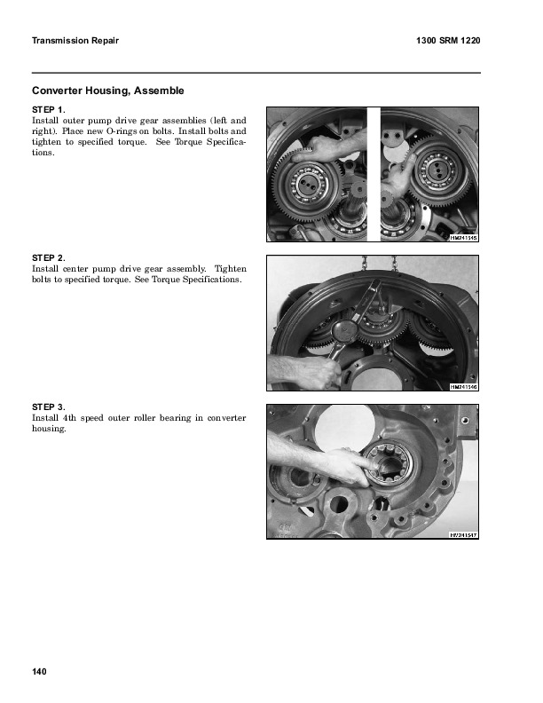
CHECKS AND ADJUSTMENTS…141
REMOVE AIR FROM THE SYSTEM…141
TROUBLESHOOTING…142
1800338…143
INTRODUCTION…143
GENERAL…143
DESCRIPTION AND OPERATION…143
BRAKE BOOSTER AND MASTER CYLINDER…143
MASTER CYLINDER…143
SERVICE BRAKE ASSEMBLY…145
PARKING BRAKE…146
REPAIRS…146
BRAKE SHOE ASSEMBLIES…146
Removal and Disassembly…146
Cleaning and Inspection…147
Assembly and Installation…149
MASTER CYLINDER…152
S3.50-5.50XL (S70-120XL) and H3.50-5.00XL (H70-110XL…152
Removal …152
Disassembly…152
Assembly…153
Installation…153
MASTER CYLINDER, E3.50-5.50XL (E70-120XL)…153
Removal and Disassebly…153
Cleaning and Inspection…154
Assembly and Installation…154
BRAKE BOOSTER…154
Removal…154
Disassembly…154
Cleaning and Inspection…155
Assembly…155
Installation…156
CHECKS AND ADJUSTMENTS…156
REMOVE THE AIR FROM THE BRAKE SYSTEM…156
ADJUST THE BRAKE PEDAL…156
ADJUST THE BRAKE SHOES…157
ADJUST THE PARKING BRAKE…158
CHECK THE RELIEF VALVE ON THE PARKING BOOSTER…158
TROUBLESHOOTING…158
1900333…160
INTRODUCTION…160
GENERAL…160
DESCRIPTION AND OPERATION…160
Hydraulic Pump…160
Main Control Valve…161
Steering Control Unit…163
Brake Booster…163
REPAIRS…163
HYDRAULIC PUMP…163
Removal…163
Disassembly…164
Cleaning and Inspection…164
Assembly…164
Installation…165
Adjust the Flow Divider…165
SPECIFICATIONS…165
TROUBLESHOOTING…166
1900339…168
INTRODUCTION…168
GENERAL…168
DESCRIPTION…168
REPAIRS…170
REMOVAL AND DISASSEMBLY…170
CLEANING…170
INSPECTION…170
ASSEMBLY AND INSTALLATION…171
TROUBLESHOOTING…172
GENERAL…172
190097…173
INTRODUCTION…173
DESCRIPTION…173
OPERATION…173
Flow Control Valve…175
Relief Valve…175
REPAIRS…176
REMOVAL…176
DISASSEMBLY…176
CLEANING…178
INSPECTION…178
ASSEMBLY…179
INSTALLATION…180
CHECKS AND ADUSTMENTS…181
CHECK THE OUTPUT OF THE PUMP…181
CHECK FOR AIR IN THE HYDRAULIC SYSTEM…181
TROUBLESHOOTING…183
200077…186
INTRODUCTION…186
GENERAL…186
DESCRIPTION…186
OPERATION…187
Lift Section…188
Tilt Section…188
Relief Valve…190
SOLENOID VALVE FOR AUXILIARY FUNCTION…191
Operation…191
REPAIRS…191
MAIN CONTROL VALVE…191
Removal and Disassembly…191
Cleaning and Inspection…192
Assembly…192
Installation…192
SOLENOID VALVE FOR AUXILIARY FUNCTION…192
Removal and Disassembly…192
Assembly and Installation…194
CHECKS AND ADJUSTMENTS…194
PRESSURE RELIEF VALVES…194
Primary Relief Valve…194
Seconday Relief Valve…195
CONTROL LEVER ARRANGEMENT…195
TROUBLESHOOTING…198
SPECIFICATIONS…200
2100103…201
INTRODUCTION…204
GENERAL…204
DESCRIPTION…204
REPAIRS…204
REMOVAL…204
DISASSEMBLY…204
CLEANING…204
ASSEMBLY…204
Tilt Cylinders for the XM and XMS Models…204
Tilt Cylinders with O-Ring or Single Lip Seals…206
Tilt Cylinders for H700-800A and Early Model H700-920B…206
INSTALLATION…206
Tilt Cylinders with Chevron Packing…206
CHECKS AND ADJUSTMENTS…210
CHECK THE TILT CYLINDERS FOR LEAKS…210
ADJUST THE TILT CYLINDER STROKE AND THE MAST TILT ANGLE…210
TROUBLESHOOTING…213
2200106…216
INTRODUCTION…216
GENERAL…216
DESCRIPTION AND OPERATION…216
REPAIRS…218
REMOVAL…218
DISSASEMBLY…218
CLEANING…219
ASSEMBLY…219
INSTALLATION…219
CHECKS AND ADJUSTMENTS…220
GENERAL…220
TROUBLESHOOTING…222
2200143…224
INTRODUCTION…224
GENERAL…224
DESCRIPTION…224
GENERAL…224
STEERING COLUMN GAUGES, METERS AND INDICATORS…227
LED DISPLAY PANEL…227
Battery Discharge Indicators …227
Brush Wear Indicators…228
Motor Temperature Indicators…229
"LX" SERIES INSTRUMENT PANEL DISPLAY…230
Hourmeter Functions…231
Battery Indicator Function…231
Status Code Function…231
CHECKS AND ADJUSTMENTS…231
GENERAL…231
REPLACEMENT…232
GENERAL…232
METER REPLACEMENT…232
SENDER REPLACEMENT…233
Fuel Level Sender…233
Pressure And Temperature Sender…234
I.T.W. DISPLAY PANEL…234
Removal…234
SPECIFICATIONS…235
TROUBLESHOOTING…236
2200144…237
ELECTRICAL WARNING DEVICES…237
GENERAL…237
DESCRIPTION…237
Operator Controlled Horns…237
System Warning Lights, Buzzers and Bells…237
Reverse Warning Horns…238
Warning Lights…238
REPLACEMENT…239
General…239
Replacing Horns or Bells…239
Replacing Horn Relay or Buzzer…239
Replacing Warning Lights…239
Light Assemblies…240
Replacing Flashing Units…240
22002…241
INTRODUCTION…241
GENERAL…241
DESCRIPTION…241
REPAIRS…243
GENERAL…243
REMOVAL AND DISASSEMBLY (Type A)…243
CLEANING…243
ASSEMBLY (Type A)…244
REMOVAL AND DISAASSEMBLY (Type B)…246
CLEANING…248
ASSEMBLY (Type B)…248
INSTALLATION (Type A and Type B)…249
CHECKS AND ADJUSTMENTS…249
GENERAL…249
CHECK THE ALTERNATOR FOR LOW OUTPUT (Type A or Type B)…250
CHECK THE ALTERNATOR FOR HIGH OUTPUT (Type A or Type B)…251
CHECK THE CIRCUIT FOR THE BRUSHES…253
Delco Alternators…253
Motorola Alternators…253
CHECK THE DIODES…253
CHECK THE DIODE BRIDGE…253
Delco and Leece–Neville Alternators…253
Motorola Alternators…253
CHECK THE FIELD WINDING FOR THE ROTOR…254
CHECK THE WINDINGS IN THE STATOR…254
CHECK THE VOLTAGE REGULATOR…255
TROUBLESHOOTING…255
2200463…256
MICROPROCESSOR SPARK TIMING SYSTEM (MSTS)…256
GENERAL…256
DESCRIPTION…256
What MSTS Does…258
How MSTS Begins Operation…258
OPERATION…258
Pulse Generator…258
HEI Module…259
When the Engine Is Being Started…259
When the Engine Is Running…261
Manifold Absolute Pressure (MAP)…261
Coolant Temperature Sensor (CTS)…261
Electronic Control Module (ECM), Corrections…262
The Initial Timing Connector…262
Gasoline and LPG Conversions…263
TROUBLESHOOTING…265
GENERAL…265
TOOLS AND TEST EQUIPMENT…265
MSTS TROUBLESHOOTING…266
Test Description…266
IGNITION SYSTEM TROUBLESHOOTING…268
Test Description…268
ELECTRONIC SPARK TIMING (EST) TROUBLESHOOTING…271
Circuit Description…271
Test Description…271
MANIFOLD ABSOLUTE PRESSURE (MAP) TROUBLESHOOTING…274
Circuit Description…274
Test Description…274
COOLANT TEMPERATURE SENSOR (CTS) TROUBLESHOOTING…277
Circuit Description…277
Test Description…277
REPAIRS…279
DISTRIBUTOR…279
Removal…279
Disassembly…280
Inspection…280
Assembly…281
Installation…281
Igntion Timing…281
HEI MODULE…282
Test For A Fault…282
HEI Module Replacement…282
SENSING COIL…283
Test For A Fault…283
Sensing Coil Replacement…283
IGNITION COIL…283
Test For A Fault…283
ELECTRONIC CONTROL MODULE (ECM)…284
Removal…284
Installation…284
COOLANT TEMPERATURE SENSOR (CTS)…284
Removal…284
Installation…285
MANIFOLD ABSOLUTE PRESSURE (MAP)…285
Removal…285
Installation…285
PRESSURE CONVERSION CHART…286
2200468…287
ELECTRONIC ENGINE CONTROL, TROUBLESHOOTING AND REPAIR…287
GENERAL…287
Engine Data…287
LIGHT BULB CHECK…287
SYSTEM CHECK…289
TROUBLESHOOTING WITH THE FAULT MONITOR SYSTEM IN THE ECM…289
How To Clear A Code…290
Fault In The ECM…290
Fault In The PROM…291
CalPak Not Installed…291
Fuel Control…291
Idle Air Control (IAC)…291
Fuel Pump Circuit…291
Coolant Temperature Sensor (CTS)…292
Manifold Absolute Pressuer Sensor (MAP)…292
Throttle Position Sensodr (TPS)…292
Output Check, Throttle Position Sensor…292
Electronic Spark Timing…292
Engine Crank Signal…293
Distributor Reference Signal…293
TROUBLESHOOTING CHARTS…294
CHART A-1-No "Check Engine" Light…294
Circuit Description, "Check Engine" Light…294
CHART A-1-No "Check Engine" Light…295
CHART A-2-No ALDL Data Or No Code 12 From "Check Engine" Light. The "Check Engine" Light Is Continuosly Illuminated…296
Circuit Description, "Check Engine" Light…296
CHART A-2-No ALDL Data Or No Code 12 From "Check Engine" Light. The "Check Engine" Light Is Continuously Illuminated…297
CHART A-3-Starter Cranks The Engine, But Will Not Run…298
Circuit Description…299
CHART A-4-Fuel Injector Circuit…300
Circuit Description…300
CHART A-5-Fuel Pump Relay Circuit…302
Circuit Description…302
CHART A-6-Fuel System Pressure Test…304
Circuit Description…304
CHART A-7-MAP Output Check…306
Circuit Description…306
CHART A-8-Engine Crank Signal Check…308
Circuit Description…308
CHART A-9-Ignition System Troubleshooting…309
CHART A-9 Ignition System Troubleshooting Chart…310
CHART A-10-Idle Air Control (IAC) System…312
Circuit Description…312
FAULT CODES…314
CODE 14-Coolant Temperature Sensor Circuit (Indicates High Temperature)…314
Circuit Description…314
CODE 15-Coolant Temperature Sensor Circuit (Indicates Low Temperature…316
Circuit Description…316
CODE 21-Throttle Position Sensor Circuit (Signal Voltage High) …318
Circuit Description…318
CODE 22-Throttle Position Sensor Circuit (Signal Voltage Low) …320
Circuit Description…320
CODE 31-Engine Governor Circuit…322
Circuit Description…322
CODE 33-MAP Sensor Circuit, Signal Voltage High (Low Vacuum…324
Circuit Description…324
CODE 34-MAP Sensor Circuit, Signal Voltage Low (High Vacuum)…326
Circuit Description…326
CODE 42-Electronic Spark Timing (EST)…328
Circuit Description…328
CODE 54-Fuel Pump Circuit (Low Voltage)…330
Circuit Description…330
CODE 51-PROM In The ECM Has A Fault …332
CODE 52-Fuel CalPak Is Missing…332
CODE 55-ECM Has A Fault…332
TROUBLESHOOTING, POOR OPERATION…332
General…332
Make A Careful Visual Check…332
FAULT: Fuel Usage Too High…332
FAULT: Codes Or Performance That Is Not Regular…333
FAULT: "Dieseling"…333
FAULT: "Backfire"…333
FAULT: Rough Idle or Engine Stalls During Idle…333
FAULT: Smoke In The Exhaust Gases…334
FAULT: Engine is Difficult To Start…334
FAULT: Variation In Engine Power When The Throttle Is Held Steady…335
FAULT: Decreased Engine Power…335
FAULT: "Detontion"…335
FAULT: Engine Momentarily Does Not Increase Power When Throttle Changes…336
FAULT: One Cylinder In The Engine Does Not Operate Correctly. The Engine Does Not Idle Correctly…336
REPAIRS, FUEL SYSTEM COMPONENTS …338
General…338
Vacuum Ports…338
Throttle Body Injection (TBI) Unit…338
TBI Unit, Removal…338
TBI Unit, Cleaning and Inspection…339
TBI Unit, Installation…339
Cover For Fuel Meter Body, Replacement…339
Fuel Injectors…340
Fuel Injectors, Removal…340
Fuel Injectors, Installation…341
Pressure Regulator, Removal…341
Pressure Regulator, Inspection…341
Pressure Regulator, Installation …341
Fuel Meter Body, Removal…342
Fuel Meter Body, Installation…342
Throttle Position Sensor (TPS), Removal…342
Throttle Position Sensor (TPS), Installation…342
Idle Air Control (IAC) Valve, Removal…343
Cleaning and Inspection…343
Idle Air Control (IAC) Valve, Installation…343
Governor Throttle Drive Assembly, Removal…343
Governor Throttle Drive Assembly, Inspection…343
Cleaning and Lubrication…344
Governor Throttle Drive Assembly, Installation…344
Governor Drive Motor, Removal…345
Governor Drive Motor, Cleaning and Lubrication…345
Governor Drive Motor, Installation…346
Governor Drive Motor, Inspection…346
Throttle Body, Removal and Disassembly…346
Throttle Body, Inspection…346
Throttle Body, Assembly and Installation…346
Fuel Pump, Removal and Disassembly…347
Fuel Pump, Inspection…347
REPAIRS, ELECTRICAL COMPONENTS…347
General…347
Ignition Coil Test…347
Ignition Module Test…348
Distributor, Removal…348
Distributor, Disassembly…349
Distributor, Assembly…349
Distributor, Installation…350
Firing Order…351
Ignition Timing…351
Ignition Coil, Removal…352
Ignition Coil, Installation…352
Procedures For Spark Plugs, Spark Plug Wires And Boots …352
Troubleshooting of Spark Plugs…353
Coolant Temperature Sensor (CTS), Replacement …354
Manifold Absolute Pressure (MAP) Sensor, Replacement…354
Oil Pressure Switch, Replacement…355
Coolant Temperature Sender, Replacement…355
Wire Harness…355
Connectors And Terminals…355
Electronic Control Module (ECM)…359
ECM CONNECTOR A-B IDENTIFICATION…363
ECM CONNECTOR C-D IDENTIFICATION…364
SPECIAL TOOLS…365
2200473…368
INTRODUCTION…368
GENERAL…368
DESCRIPTION AND OPERATION…368
GENERAL…368
ECM (ELECTRONIC CONTROL MODULE)…368
ALDL Connector…370
How The ECM Begins Operation…370
ELECTRONIC ENGINE CONTROL…371
What The ECM Does…371
Pulse Generator, EST Distributor…372
EST Module(See FIGURE 9.)…373
When the Engine Is Being Started…373
When the Engine Is Running…375
Electronic Control Module (ECM) With EST Distrubutor, Corrrections…375
What The ECM Does…375
FUEL CONTROL…376
Throttle Body Injection…376
Fuel Injectors…377
Fuel Pressure Regulator…377
Throttle Position Sensor…377
Idle Air Control…377
Governor Motor And Throttle Drive Assembly…378
Vacuum Ports…380
Fuel Pump…380
ECM SENSORS AND CONTROLLERS…382
Manifold Absolute Pressure (MAP)…382
Coolant Temperature Sensor (CTS)…382
Initial Timing Connector (EST Distributor)…382
4000135…384
SAFETY PROCEDURES WHEN WORKING NEAR THE MAST…384
LIFT CYLINDERS…387
GENERAL…387
DESCRIPTION…387
Lowering Control Valve…387
Cylinders (General)…390
Cylinders (H520-620B,H700-800A)…392
Cylinders (H360-460B)…393
Cylinders (Two-Speed)…393
REPAIRS…394
REMOVAL OF THE LIFT CYLINDER WITHOUT REMOVING THE MAST…394
Standard Masts with the Main Lift Cylinder Fastened to the Crossmember of the Inner Mast…394
Standard and Full Free-Lift Masts with the Lift Cylinder to a Crosshead…398
Masts that have Two Cylinders, A Main Lift Cylinder and a Free-Lift Cylinder…396
DISASSEMBLY…396
ASSEMBLY…398
INSTALLATION OF THE LIFT CYLINDER IN THE MAST…398
Standard Masts with the Main Lift Cylinder Fastened to the Crossmember of the Inner Mast…398
Standard and Full-Free-Lift Masts with the Lift Cylinder Fastened to a Crosshead…398
CHEVRON PACKING…399
LIFT CYLINDERS FOR VISTA MASTS…402
DESCRIPTION…402
Lowering Control Valve…404
REMOVAL…405
DISASSEMBLY…405
ASSEMBLY…405
INSTALLATION…406
Main Lift Cylinders…406
Free-Lift Cylinders…406
CHECKS AND ADJUSTMENTS…407
CHECK FOR LEAKS IN LIFT SYSTEM…407
TROUBLESHOOTING…408
SPECIFICATIONS…409
4000340…410
VISTA® MASTS…410
GENERAL…410
DESCRIPTION AND OPERATION…410
CARRIAGES…410
TWO-STAGE MAST WITH LIMITED FREE-LIFT…410
TWO-STAGE MAST WITH FULL FREE-LIFT MAST…411
THREE-STAGE MAST WITH FULL FREE-LIFT…412
REPAIRS…414
SAFETY PROCEDURES WHEN WORKING NEAR THE MAST (1 OF 2)…414
SAFETY PROCEDURES WHEN WORKING NEAR THE MAST (2 OF 2)…415
FORKS…415
Forks, Removal And Installation…415
CARRIAGE…417
Removal…417
SIDE-SHIFT CARRIAGE (EARLIER DESIGNS)…418
Disassembly, Side Shift Carriage…418
Assembly, Side Shift Carriage…420
Installation…421
SIDE-SHIFT CARRIAGE (1993 AND LATER DESIGN)…421
Removal…421
Repairs…422
Installation…423
TABLE 1. WEIGHT OF MAST PARTS…423
TWO-STAGE MAST WITH LIMITED FREE-LIFT…424
Removal…424
Disassembly…424
Cleaning and Inspection…426
Assembly…426
Installation…427
TWO-STAGE MAST WITH FULL FREE-LIFT…427
Removal…427
Disassembly…427
Cleaning and Inspection…428
Assembly…428
Installation…428
THREE-STAGE MAST WITH FULL FREE LIFT…429
Removal…429
Disassembly…429
Cleaning and Inspection…430
Assembly…430
Installation…432
CHECKS AND ADJUSTMENTS…434
CHECK THE OPERATION OF THE MAST…434
CHECK FOR LEAKS IN THE LIFT AND TILT SYSTEM…434
Lift System…434
Tilt System…434
ADJUST THE TILT CYLINDER STROKE AND THE BACKWARD TILT ANGLE…435
LIFT CHAIN ADJUSTMENTS…435
MAST ADJUSTMENTS…436
CARRIAGE ADJUSTMENT…437
TROUBLESHOOTING…440
600412…442
PERKINS DIESEL ENGINES, SERIES 1000…442
1.1 GENERAL…442
GENERAL SAFETY RULES…442
Viton Seals…442
1.2 DESCRIPTION…445
1.3 Engine Serial Number Codes…445
1.4 Engine Data…445
1.5 1004–4 ENGINE…446
1.6 1004–4T ENGINE…446
1.7 1006–6 ENGINE…446
1.8 1006–6T ENGINE…446
1.9 REMOVAL AND INSTALLATION…446
CYLINDER HEAD ASSEMBLY…447
1.10 VALVE COVER…447
1.11 Removal…447
1.12 Installation…447
1.13 ROCKER ARM ASSEMBLY…447
1.14 Removal…447
1.15 Installation…447
1.16 Disassembly…448
1.17 Inspection…448
1.18 Assembly…448
1.19 VALVE CLEARANCE ADJUSTMENTS…448
1.20 Four Cylinder Engines…449
1.21 Six Cylinder Engines…449
1.22 VALVE SPRINGS…449
1.23 CYLINDER HEAD ASSEMBLY…451
1.24 Removal…451
1.25 Installation…452
1.26 VALVES AND VALVE SPRINGS…455
1.27 Removal…455
1.28 Inspection…456
1.29 Installation…456
1.30 VALVE GUIDES…456
1.31 Inspection…456
1.32 Removal…457
1.33 Installation…457
1.34 CYLINDER HEAD AND VALVE SEATS…457
1.35 Inspection…457
1.36 Repair…458
1.37 Installation Of New Valve Seats…458
PISTON AND CONNECTING ROD ASSEMBLIES…459
1.38 ROD BEARINGS…459
1.39 Removal…459
1.40 Installation…460
1.41 PISTON AND CONNECTING ROD ASSEMBLY…460
1.42 Service Note…460
1.43 Removal…460
1.44 Installation…461
1.45 PISTON RINGS…462
1.46 Removal…462
1.47 Inspection…462
1.48 Installation…463
1.49 PISTON AND CONNECTING ROD…464
1.50 Disassembly…464
1.51 Inspection…464
1.52 Installation…464
1.53 PISTON COOLING JETS…465
1.54 Removal…465
1.55 Installation…465
CRANKSHAFT ASSEMBLY…466
1.56 GENERAL…466
1.57 CRANKSHAFT PULLEY…466
1.58 Removal, Engines AA and AB…466
1.59 Installation, Engines AA and AB…466
1.60 Removal, Engines YA and YB…466
1.61 Installation, Engines YA and YB…466
1.62 REAR OIL SEAL…467
1.63 Replacement…467
1.64 MAIN BEARINGS…468
1.65 Removal…468
1.66 Installation…468
1.67 THRUST WASHERS…469
1.68 Check The Axial Movement Of The Crankshaft…469
1.69 Removal…470
1.70 Installation…470
1.71 CRANKSHAFT…470
1.72 Removal…470
1.73 Inspection…471
1.74 Installation…471
TIMING CASE AND TIMING GEARS…473
1.75 GENERAL…473
1.76 TIMING CASE COVER…473
1.77 Removal…473
1.78 Installation…473
1.79 FRONT OIL SEAL…474
1.80 Removal…474
1.81 Installation…474
1.82 IDLER GEAR AND HUB…474
1.83 Removal…474
1.84 Installation…475
1.85 GEAR FOR THE FUEL INJECTION PUMP OR THE CAMSHAFT GEAR…476
1.86 Removal…476
1.87 Installation…476
1.88 CRANKSHAFT GEAR…477
1.89 Removal…477
1.90 Installation…477
1.91 TIMING CASE…477
1.92 Removal…477
1.93 Installation…477
1.94 CAMSHAFT AND TAPPETS…478
1.95 Removal…479
1.96 Installation…479
ENGINE BLOCK ASSEMBLY…480
1.97 DESCRIPTION…480
1.98 ENGINE BLOCK…480
1.99 Disassembly…480
1.100 Inspection…481
1.101 Assembly…481
1.102 CYLINDER LINER…481
1.103 Inspection…481
1.104 Hone…482
1.105 Removal…482
1.106 Installation…483
TURBOCHARGER, ENGINES AB AND YB…484
1.107 GENERAL…484
1.108 Removal…484
1.109 Installation…485
1.110 Clean The Impeller And Compressor Housing…485
LUBRICATION SYSTEM…486
1.111 GENERAL…486
1.112 OIL FILTER, REPLACEMENT…486
1.113 OIL SUMP…487
1.114 Removal…487
1.115 Installation…487
1.116 OIL PUMP…487
1.117 Removal…487
1.118 Inspection…488
1.119 Installation…488
1.120 RELIEF VALVE…489
1.121 Removal…489
1.122 Disassembly…489
1.123 Inspection…490
1.124 Installation…490
FUEL SYSTEM…490
1.125 DESCRIPTION…490
1.126 CAV FUEL INJECTION PUMP…491
1.127 Removal…491
1.128 Installation…491
1.129 CAV FUEL INJECTION PUMP, CHECKS AND ADJUSTMENTS…492
1.130 Timing Gear Marks…492
1.131 How To Set Number 1 Piston To TDC On The Compression Stroke…493
1.132 Check The Valve Timing…493
1.133 Check The Timing Of The Fuel Injection Pump…494
1.134 Check The Timing Mark Of The Fuel Injection Pump…494
1.135 Check The Engine Timing Mark…495
1.136 REMOVE AIR FROM THE FUEL SYSTEM…496
1.137 Fuel Injection Pump With Vent Tube…496
1.138 Fuel Injection Pump With Vent Screw…497
1.139 FUEL FILTER (REPLACEMENT)…498
1.140 FUEL INJECTORS…498
1.141 Removal…498
1.142 Inspection…499
1.143 Installation…500
1.144 FUEL PUMP…500
1.145 Removal…500
1.146 Disassembly…500
1.147 Assembly…501
1.148 Installation…501
1.149 Test…502
COOLING SYSTEM…502
1.150 GENERAL…502
1.151 THERMOSTAT…502
1.152 Replacement…502
1.153 COOLANT PUMP…503
1.154 Removal…503
1.155 Disassembly…503
1.156 Assembly…504
1.157 Installation…504
1.158 FAN AND FAN DRIVE…504
1.159 Removal…504
1.160 Disassembly…504
1.161 Assembly…505
1.162 Installation…505
1.163 OIL COOLER…505
1.164 Removal, Engine AB…505
1.165 Removal, Engines YA and YB…505
1.166 Disassembly And Assembly…506
1.167 Installation, Engine AB…506
1.168 Installation, Engines YA and YB…507
1.169 By–Pass Valve, Oil Cooler…507
FLYWHEEL AND FLYWHEEL HOUSING…507
1.170 GENERAL…507
1.171 FLYWHEEL…507
1.172 Removal…507
1.173 Ring Gear (Replacement)…507
1.174 Installation…507
1.175 FLYWHEEL HOUSING…508
1.176 Removal…508
1.177 Installation…508
ELECTRICAL EQUIPMENT…509
1.178 DRIVE BELTS…509
1.179 ALTERNATOR…510
1.180 STARTER MOTOR…510
1.181 Removal…510
1.182 Installation…510
1.183 COLD START AID…510
AIR COMPRESSOR, ENGINES YA AND YB…510
1.184 GENERAL…510
1.185 Air Compressor, Removal, WABCO…510
1.186 Compressor Drive, Inspection…511
1.187 Air Compressor, Installation, WABCO…511
1.188 Compressor Drive, Disassembly, WABCO…511
1.189 Compressor Drive, Assembly, WABCO…512
1.190 Air Compressor, Removal, BENDIX…512
1.191 Air Compressor, Installation, BENDIX…513
1.192 Compressor Drive, Disassembly, BENDIX…514
1.193 Compressor Drive, Assembly, BENDIX…514
ENGINE SPECIFICATIONS…516
1.194 CYLINDER HEAD ASSEMBLY…516
1.195 Cylinder Head…516
1.196 Valve Guides…516
1.197 Inlet Valves…517
1.198 Exhaust Valves…517
1.199 Double Valve Springs To Outer…517
1.200 Double Valve Springs To Inner…517
1.201 Single Valve Springs…517
1.202 Tappets…517
1.203 Rocker Arm Shaft…517
1.204 Rocker Arms And Bushings…518
1.205 PISTON AND CONNECTING RODS…518
1.206 Pistons, Engines AA And YA…518
1.207 Pistons, Engines AB And YB…518
1.208 Piston Rings, Engines AA And YA…518
1.209 Piston Rings, Engines AB And YB…518
1.210 Connecting Rods, Engines AB And YB…519
1.211 Connecting Rods, Engines AB And YB…519
1.212 Piston Pins, Engines AA And YA…519
1.213 Piston Pins, Engines AB and YB…519
1.214 Small End Bushings, Engines AA And YA…519
1.215 Small End Bushings, Engines AB And YB…519
1.216 Connecting Rod Bearings, Engines AA And YA…520
1.217 Connecting Rod Bearings, Engines AB And YB…520
1.218 Piston Cooling Jets, Engines AB And YB…520
1.219 CRANKSHAFT ASSEMBLY…520
1.220 Crankshaft…520
1.221 Crankshaft Heat Treatment…520
1.222 Crankshaft Overhaul…520
1.223 Main Bearings…522
1.224 Crankshaft Thrust Washers…522
1.225 TIMING CASE AND DRIVE ASSEMBLY…522
1.226 Camshaft…522
1.227 Camshaft Thrust Washer…522
1.228 Camshaft Gear…523
1.229 Gear For Fuel Injection Pump…523
1.230 Crankshaft Gear…523
1.231 Idler Gear And Hub…523
1.232 ENGINE BLOCK ASSEMBLY…523
1.233 Engine Block…523
1.234 Cylinder Liners…523
1.235 TURBOCHARGER…524
1.236 LUBRICATION SYSTEM…524
1.237 Oil Pump, Engines AA And AB…524
1.238 Oil Pump, Engines YA And YB…524
1.239 Relief Valve…524
1.240 Oil Filter…524
1.241 FUEL SYSTEM…524
1.242 Cav Fuel Injection Pump…524
1.243 FUEL INJECTORS…525
1.244 Fuel Pump, Engines AA And AB…526
1.245 Fuel Pump, Engines YA And YB…526
1.246 Fuel Filter…526
1.247 COOLING SYSTEM…526
1.248 Coolant Pump…526
1.249 Thermostat…527
1.250 Fan Drive Housing…527
1.251 FLYWHEEL AND HOUSING…527
1.252 Limits for flywheel ''run out'' and alignment (total indicator reading)…527
1.253 ELECTRICAL EQUIPMENT…527
1.254 Alternator…527
1.255 Starter Motor…527
1.256 Cold Start Aid…527
TORQUE SPECIFICATIONS…528
SPECIAL TOOLS…529
600590…533
GM 4.3 LITRE V-6…533
INTRODUCTION…533
DESCRIPTION…533
ENGINE, REMOVAL AND INSTALLATION…534
CYLINDER HEAD…534
Removal And Disassembly…534
Cleaning And Inspection…534
Repairs, Valve Guides and Seats…534
Repairs, Valves…535
Repairs, Valve Seats…535
Valve Springs…536
Studs For The Rocker Arms (Early Models)…537
Studs For The Rocker Arms (Late Models)…538
Assembly And Installation…538
CYLINDER BLOCK, CLEANING AND INSPECTION…540
PISTON BORE PREPARATION…540
ENGINE MOUNTS…540
LUBRICATION SYSTEM…540
Oil Pump, Removal and Disassembly…540
Cleaning and Inspection…541
Oil Pump, Assembly and Installation…541
Oil Sump, Installation…541
TIMING COVER, TIMING SPROCKETS, CAMSHAFT AND VALVE LIFTERS…542
Timing Cover, Removal…542
Installation…543
Timing Sprockets, Removal…544
Timing Sprockets, Installation…544
Camshaft, Removal…544
Camshaft, Inspection…544
Camshaft, Installation…544
Balance Shaft, Removal…545
Balance Shaft, Installation…546
Hydraulic Valve Lifters, Removal…547
Hydraulic Valve Lifters, Disassembly…547
Hydraulic Valve Lifters, Cleaning And Inspection…547
Hydraulic Valve Lifters, Assembly…548
Hydraulic Valve Lifters, Installation…548
CRANKSHAFT…549
Removal…549
Inspection and Repair…549
How To Check The Clearance Between The Main Bearings And Their Journals…550
Installation…551
PISTON AND CONNECTING ROD ASSEMBLIES…552
Connecting Rod Bearings, Replacement…552
Piston And Connecting Rod Assemblies, Removal…553
Disassembly…553
Piston, Cleaning And Inspection…553
Cylinder Bores, Inspection And Repair…554
Piston Rings…555
Assembly…555
Piston And Connecting Rod Assemblies, Installation…556
FLYWHEEL AND FLYWHEEL HOUSING…556
Flywheel Repairs…556
Flywheel, Installation…556
Flywheel Housing…557
Engine Adapter…557
COOLANT PUMP…557
THERMOSTAT…557
FAN MOUNT, EARLY MODELS…557
FAN MOUNT ASSEMBLY, LATE MODELS…558
DRIVE BELT, INSTALLATION…559
CHECKS AND ADJUSTMENTS…561
VALVE CLEARANCE ADJUSTMENT, EARLY MODELS…561
VALVE CLEARANCE ADJUSTMENT, NEW MODELS…561
CHECK THE COMPRESSION…561
ENGINE SPECIFICATIONS…562
Engine Data…562
Cylinder head…562
Hydraulic Valve Lifter…562
Camshaft…562
Pistons…562
Crankshaft…563
Connecting Rods…563
Connecting Rods…563
Balance Shaft…563
Cooling System…563
Lubrication System…563
TORQUE SPECIFICATIONS…564
TROUBLESHOOTING…565
600705…568
PERKINS DIESEL ENGINES, 1004-42 (AR), 1006-60 (YG), 1006-60T (YH) …568
GENERAL…568
General Safety Rules…568
DESCRIPTION…570
Engine Serial Number Codes…571
Engine Data…572
1004-42 (AR) ENGINE (Low Governed Speed)…572
1004-42 (AR) ENGINE (High Governed Speed)…572
1006-60 (YG) ENGINE…572
1006-60T (YH) ENGINE…572
REMOVAL AND INSTALLATION…573
Lifting The Engine…573
CYLINDER HEAD ASSEMBLY…573
VALVE COVER…573
Removal…573
Installation…574
ROCKER ARM ASSEMBLY…574
Removal…574
Installation…574
Disassembly…574
Inspection…575
Assembly…575
VALVE CLEARANCE ADJUSTMENTS…575
Four Cylinder Engines…575
Six Cylinder Engines…576
VALVE SPRINGS…576
CYLINDER HEAD ASSEMBLY…577
Removal…577
Installation…580
VALVE AND VALVE SPRINGS…584
Removal…584
Inspection…585
Installation…585
VALVE GUIDES…585
Inspection…585
Removal…586
Installation…586
CYLINDER HEAD AND VALVE SEATS…587
Inspection…587
Repair…587
Installation Of New Valve Seats…588
PISTON AND CONNECTING ROD ASSEMBLIES…588
ROD BEARINGS…589
Removal…589
Installation…590
PISTON AND CONNECTING ROD ASSEMBLY…590
Service Note…590
Removal…591
Installation…591
PISTON RINGS…592
Removal…592
Inspection…592
Installation…593
PISTON AND CONNECTING RODS…594
Disassembly…594
Inspection…595
How To Select the Correct Replacements…595
Installation…596
PISTON COOLING JETS…596
Removal…596
Installation…596
CRANKSHAFT ASSEMBLY…597
GENERAL…597
CRANKSHAFT PULLEY…598
Removal, Engine AR…598
Removal, Engines YG and YH…598
Inspection…598
Installation, Engine AR …599
Installation, Engine YG and YH…599
REAR OIL SEAL…600
Replacement…600
MAIN BEARINGS…601
Removal…601
Inspection…601
Installation…602
THRUST WASHERS…602
Check The Axial Movement Of The Crankshaft…602
Removal…603
Installation…603
CRANKSHAFT…604
Removal…604
Inspection…604
Installation…604
FLYWHEEL…606
Removal…606
Ring Gear (Replacement)…606
Installation…606
FLYWHEEL HOUSING…607
Removal…607
Installation…607
TIMING CASE AND TIMING GEARS…608
GENERAL…608
TIMING CASE COVER…608
Removal…608
Installation…608
FRONT OIL SEAL…609
Removal…609
Installation…609
CRANKSHAFT PULLEY WEAR SLEEVE…610
Installation…610
IDLER GEAR AND HUB…610
Removal…610
Installation…611
AIR COMPRESSOR, DRIVE, BENDIX…612
Disassembly…612
Compressor Drive, Assembly…613
GEAR FOR THE FUEL INJECTION PUMP…613
Removal…613
Installation…614
CAMSHAFT GEAR…615
Removal…615
Installation…615
CRANKSHAFT GEAR…616
Removal…616
Installation…616
TIMING CASE…616
Removal…616
Installation…617
CAMSHAFT AND TAPPETS…618
Removal…618
Installation…618
CYLINDER BLOCK ASSEMBLY…619
DESCRIPTION…619
CYLINDER BLOCK…619
Disassembly…619
Inspection…620
Assembly…620
CYLINDER BORE (4-CYLINDER ENGINES)…620
CYLINDER LINER (6-CYLINDER ENGINES)…621
Inspection…621
To Check the Condition of a Cylinder Liner…621
Removal…622
Installation (Service Liner)…623
Installation (Partially Finished Liner)…624
ENGINE TIMING…625
GENERAL DESCRIPTION…625
How To Set Number 1 Piston To TDC On The Compression Stroke…626
How To Set Number 1 Piston To TDC On The Compression Stroke (Alternate Procedure)…627
Check The Valve Timing…627
Check The Timing Of The Fuel Injection Pump…628
TURBOCHARGER, ENGINE YH…629
GENERAL…629
Removal…629
Installation…629
Clean The Impeller And Compressor Housing…630
LUBRICATION SYSTEM…631
GENERAL…631
OIL FILTER, REPLACEMENT…631
FILTER HEAD…632
To Remove and to Install…632
OIL SUMP…632
Removal…632
Installation…633
OIL PUMP…633
Removal…633
Inspection…633
Installation…634
RELIEF VALVE…635
Removal…635
Disassembly…635
Inspection…636
Assembly…636
Installation…636
IDLER GEAR SHAFT, REPLACEMENT…636
Removal…636
Removal, Alternative …637
Installation…638
Installation, Alternative…638
Installation, Alternative For 4-Cylinder Engines Only…638
FUEL SYSTEM…639
DESCRIPTION…639
FUEL INJECTION PUMP…639
Removal…639
Installation…640
FUEL INJECTION PUMP, CHECKS AND ADJUSTMENTS…641
REMOVE AIR FROM THE FUEL CHECK…642
FUEL FILTER (REPLACEMENT)…643
Canister Type…643
Quick Release Canister Type…643
FUEL INJECTORS…644
Removal…644
Inspection…645
Installation…645
FUEL PUMP…646
Removal…646
Disassembly…646
Assembly…647
Installation…647
Test…648
COOLING SYSTEM…648
GENERAL…648
THERMOSTAT…648
Thermostats…648
Remove…648
Install…648
Test…648
COOLANT PUMP…649
Removal…649
Disassembly…650
Assembly…651
Installation…654
FAN AND FAN DRIVE…655
Removal…655
Installation…655
OIL COOLER (6-CYLINDER ENGINES)…655
Removal…655
Disassembly and Assembly…655
Installation…656
By-Pass Valve, Oil Cooler…656
ELECTRICAL EQUIPMENT…656
DRIVE BELTS…656
ALTERNATOR…657
Removal…657
Installation…657
STARTER MOTOR…657
Removal…657
Installation…658
COLD START AID…658
AIR COMPRESSOR, ENGINES YG AND YH…658
GENERAL…658
Air Compressor, Removal…658
Air Compressor, Installation…659
ENGINE SPECIFICATIONS…660
CYLINDER HEAD ASSEMBLY…660
Cylinder Head…660
Valve Guides…661
Inlet Valves…661
Exhaust Valves…662
Valve Springs…662
Tappets…662
Rocker Arm Shaft…663
Rocker Arms And Bushings…663
PISTON AND CONNECTIONG RODS…663
Pistons (Engine AR)…663
Pistons (Engine YG and YH)…663
Piston Rings (Engine AR)…663
Piston Rings (Engine YG and YH)…664
Piston Pins…664
Connecting Rods…664
Small End Bushings…665
Connecting Rod Bearings, Engines AR and YG…665
Connecting Rod Bearings, Engine YH…665
Piston Cooling Jets…665
CRANKSHAFT ASSEMBLY…665
Crankshaft…665
Main Bearings…666
Crankshaft Thrust Washers…666
Crankshaft Heat Treatment…666
Crankshaft Overhaul…666
TIMING CASE AND DRIVE ASSEMBLY…668
Camshaft…668
Camshaft Thrust Washer…668
Camshaft Gear…668
Gear For Fuel Injection Pump…668
Crankshaft Gear…668
Idler Gear And Hub…668
ENGINE BLOCK ASSEMBLY…669
Cylinder Block (Engine AR)…669
Cylinder Bore Specifications (Engine AR)…669
Cylinder Block (Engine YG And YH)…670
Cylinder Liner (Engine YG And YH)…670
Cylinder Liner Specifications (Partially Finished)…670
TURBOCHARGER…671
LUBRICATION SYSTEM…671
Oil Pump, Engine AR…671
Oil Pump, Engine YG And YH…671
Idler Gear for Oil Pump…671
Relief Valve…671
Oil Filter…672
FUEL SYSTEM…672
Lucas Fuel Injection Pump…672
Fuel Injector Codes…673
Fuel Pump, Engine AR…673
Fuel Pump, Engine YG And YH…673
Fuel Filter…674
COOLING SYSTEM…674
Coolant Pump…674
Thermostat…674
Fan Drive Housing…674
FLYWHEEL AND HOUSING…674
Limits for Flywheel "Run Out" and Alignment (Total Indicator Reading)…674
ELECTRICAL EQUIPMENT…674
Alternator…674
Starter Motor…674
Cold Start Aid…674
TORQUE SPECIFICATIONS…675
SPECIAL TORQUE SPECIFICATIONS…677
SPECIAL TOOLS…678
TROUBLESHOOTING…682
List of Possible Causes…683
700626…685
COOLING SYSTEM…685
INTRODUCTION…685
DESCRIPTION…685
RADIATOR…685
RADIATOR CAP…685
THERMOSTAT…685
WATER PUMP…686
FAN AND FAN SHROUD …686
REPAIRS…686
COOLING SYSTEM CHECKS…686
Exhaust Leaks…686
RADIATOR…686
Checks…686
Cleaning The Radiator…686
Drain The Cooling System…688
Fill The Cooling System…688
WATER PUMP…688
Checks…688
THERMOSTAT…689
Checks…689
FAN AND FAN SHROUD …689
TROUBLESHOOTING…690
8000231…691
INTRODUCTION…691
NOMENCLATURE, THREADS…691
STRENGTH IDENTIFICATION…692
TABLE 1. BOLTS AND SCREWS…692
TABLE 2. STUDS AND NUTS…693
TABLE 3. TORQUE NUTS…694
TABLE 4. TORQUE NUTS WITH NYLON INSERT…695
TABLE 5. TORQUE VALUES FOR INCH FASTENERS…696
TABLE 6. TORQUE VALUES FOR METRIC FASTENERS…697
8000341…700
PERIODIC MAINTENANCE…700
GENERAL…700
SERIAL NUMBER DATA…700
HOW TO MOVE A DISABLED LIFT TRUCK…700
How To Tow the Lift Truck…700
HOW TO PUT A LIFT TRUCK ON BLOCKS…701
How To Raise the Drive Tires…701
How To Raise the Steering Tires…701
MAINTENANCE SCHEDULE…703
MAINTENANCE PROCEDURES…706
EVERY 8 HOURS OR DAILY…706
HOW TO MAKE THE CHECKS WITH THE ENGINE STOPPED…706
Hydraulic System Oil…706
Engine Oil…708
Drive Belts…708
Cooling System…708
Air Filter…708
Fuel System…709
Primary Fuel Filter, Diesel Engine…709
Battery…709
Tires and Wheels…709
Forks…710
Forks, Adjustment…710
Forks, Removal And Installation…710
Inspection of Forks, Mast, And Lift Chains…711
Operator Restraint System…713
Safety Labels…714
HOW TO MAKE THE CHECKS WITH THE ENGINE RUNNING…714
Gauges, Lights, Horn, and Fuses…714
Oil Level, Powershift Transmission…714
Oil Level, Oil Clutch System, H3.50-5.00XL (H70-110XL)…715
Control Levers and Pedals…715
Lift System Operation…715
Inching/Brake Pedal…716
Service Brakes…716
Parking Brake…716
Steering System…716
EVRY 150 HOURS OR MONTHLY…716
THRUST SCREW FOR THE DIFFERENTIAL, H6.00-7.00XL (H135-155XL)…716
LIFT CHAINS, LUBRICATION…716
DRIVE SHAFTS…717
EVERY 350 HOURS OR TWO MONTHS…717
ENGINE OIL AND FILTER…717
DRIVE BELTS…718
Perkins Diesel Engine…718
GM V-6 Engine (Early Models)…718
GM V-6 Engine (Later Models)…719
HYDRAULIC TANK BREATHER, CLEAN AND CHECK…720
BRAKE FLUID…720
LIFT CHAINS, CHECK FOR WEAR…720
FORKS, CHECK FOR WEAR AND DAMAGE…721
MAST, LUBRICATION…721
CONTROL LEVERS AND PEDALS, LUBRICATION…721
STEERING AXLE, LUBRICATION…722
FUEL SYSTEM, CHECKS AND ADJUSTMENTS…722
Diesel Fuel System…722
LPG Carburetor (Early Models)…722
Gasoline Carburetor (Early Models)…723
Fuel Injection (Late Models)…723
EVERY 1000 HOURS OR SIX MONTHS…723
PCV VALVE, GM V-6…723
MANIFOLD HEAT VALVE, GM V-6 (EARLY MODELS)…723
CRANKCASE BREATHER, GM-V6…723
IGNITION SYSTEM (GM V-6)…723
VALVE CLEARANCE ADJUSTMENT…724
FUEL FILTER (REPLACEMENT), DIESEL ENGINE…724
REMOVE AIR FROM THE FUEL SYSTEM: PERKINS 1004-4 DIESEL ENGINE…724
Fuel Injection Pump With A Vent Tube…724
Fuel Injection Pump With A Vent Screw…725
REMOVE AIR FROM THE FUEL SYSTEM: PERKINS 4.2482 DIESEL ENGINE…726
CHECK THE OIL LEVEL IN THE TRANSMISSION…726
Manual Transmission, H3.50-5.00XL (H70-110XL)…726
Speed Reducer For The Powershift Transmission, H3.50-5.00XL (H70-110XL)…727
Manual Transmission, H6.00-7.00XL (H135-155XL)…727
Differential And Drive Axle For The Powershift Transmission, H6.00-7.00XL (H135-155XL…727
Differential, Speed Reducer, And Drive Axle For The Manual Transmission, H6.00-7.00XL (H135-155XL)…727
EVERY 2000 HOURS OR YEARLY…727
HYDRAULIC SYSTEM…727
Replace the Hydraulic Oil and Filter, H3.50-5.00XL (H70-110XL)…727
Replace the Hydraulic Oil and Filter, H6.00-7.00XL (H135-155XL)…728
CHANGE THE OIL AND REPLACE THE OIL FILTER, POWERSHIFT TRANSMISSION, ALL UNITS…728
CHANGE THE OIL, MANUAL TRANSMISSION, H3.50-5.00XL (H70-110XL)…728
CHANGE THE OIL, MANUAL TRANSMISSION, H6.00-7.00XL (H135-155XL)…728
CHANGE THE OIL, SPEED REDUCER, POWERSHIFT TRANSMISSION, H3.50-5.00XL (H70-110XL)…729
CHANGE THE OIL AND FILTER, OIL CLUTCH SYSTEM, H3.50-5.00XL (H70-110XL)…729
CHANGE THE OIL, DIFFERENTIAL AND DRIVE AXLE FOR THE POWERSHIFT TRANSMISSION, H6.00-7.00XL (H135-155XL)…729
CHANGE THE OIL, DIFFERENTIAL, SPEED REDUCER, AND DRIVE AXLE FOR MANUAL TRANSMISSION, H6.00-7.00XL (H135-155XL)…729
COOLING SYSTEM…730
WHEEL BEARINGS…730
Steering Wheels, lubrication…730
Drive Wheels, Lubrication…730
PCV VALVE, GM V-6…730
SERVICE BRAKES…730
LPG FILTER, REPLACEMENT…731
GASOLINE FUEL FILTER, REPLACEMENT…731
CHECK THE HOOD LATCH, H3.50-5.00XL (H70-110XL)…731
GENERAL PROCEDURES…732
SAFETY PROCEDURES WHEN WORKING NEAR THE MAST…732
LIFT CHAIN ADJUSTMENTS…734
FUEL INJECTORS…734
CHECK FOR LEAKS IN THE LIFT AND TILT SYSTEM…735
Check the Lift Cylinder for Leaks…735
Check the Tilt Cylinder for Leaks…735
WELDING REPAIRS…735
CHANGES TO THE OVERHEAD GUARD…736
WHEELS AND TIRES…737
Remove The Wheels From The Lift Truck…737
Remove The Wheel From The Tire…737
Install The Wheel In The Tire…739
Pneumatic Tires, Add Air To The Tires…740
Install the Wheels…740
SOLID RUBBER TIRES…741
Remove The Tire From The Wheel…741
Install The Tire On The Wheel…742
REFERENCE TABLE…743
8000342…744
8000343…752
FIGURE 1. ELECTRICAL SCHEMATIC (GASOLINE/LPG, EARLY PRODUCTION)…752
FIGURE 2. ELECTRICAL SCHEMATIC (GASOLINE/LPG, LATER PRODUCTION)…754
FIGURE 3. ELECTRICAL SCHEMATIC (DIESEL, PERKINS 4.2482)…756
FIGURE 4. ELECTRICAL SCHEMATIC (DIESEL, PERKINS 1004-4, EARLY PRODUCTION)…758
FIGURE 5. ELECTRICAL SCHEMATIC (DIESEL, PERKINS 1004-4, LATER PRODUCTION)…760
FIGURE 6. HYDRAULIC SCHEMATIC…762
FIGURE 7. HYDRAULIC SCHEMATIC, POWERSHIFT TRANSMISSION WITH MANUAL CONTROL…763
FIGURE 8. HYDRAULIC SCHEMATIC, POWERSHIFT TRANSMISSION WITH MONTROL PEDAL…764
FIGURE 9. WIRING DIAGRAM, BACK-UP ALARM…765
8000494…766
900348…780
INTRODUCTION…780
GENERAL…780
DESCRIPTION AND OPERATION…780
Fuel Tank…781
Fuel Filter and Fuel Valve Unit…781
Vaporizer…782
Carburetor…783
Governor…784
REPAIRS…786
LPG TANK…786
Removal…786
Installation…786
HYDROSTATIC RELIEF VALVE…786
Removal and Installation…786
FILTER UNIT…788
Replacement Of The Fuel Filter Element…788
Replacement of the Diaphragm and Fuel Valve …788
REPLACEMENT OF THE HOSES…788
VAPORIZER…788
Removal…788
Vaporizer Disassembly…790
Cleaning…790
Inspection…790
Vaporizer Assembly…790
Installation…792
CARBURETOR…792
Removal…792
Disassembly…792
Cleaning…793
Assembly…793
Installation…793
GOVERNOR…793
CHECKS AND ADJUSTMENTS…794
CHECK THE FILTER UNIT…794
CHECK THE VAPORIZER…794
Pressure Reducer Valve…794
Vapor Valve…794
ADJUST THE CARBURETOR…795
Idle Mixture…795
Idle Speed …795
Power Mixture…795
ADJUST THE THROTTLE LINKAGE…795
TROUBLESHOOTING…796
G005 (H70-110XL)…799
100345…800
THE FRAME…800
GENERAL…800
DESCRIPTION…800
REPAIRS…800
COUNTERWEIGHT…800
Removal…800
COUNTERWEIGHT…801
Installation…801
HOOD…801
Removal…801
HOOD…801
Installation…801
OVERHEAD GUARD…802
Removal…802
Installation…802
OPERATOR RESTRAINT SYSTEM…802
RADIATOR…802
Removal…802
Installation…803
EXHAUST SYSTEM…803
Muffler Replacement…803
ENGINE…803
Removal…803
Installation…806
FUEL AND HYDRAULIC TANKS…807
Inspection…807
Repairs, Small Leaks…807
Repairs, Large Leaks…807
Cleaning…807
Other Methods Of Preparation For Repair…808
SAFETY LABELS…809
CAB…809
Cab Repalacement…809
Window Repalcement…809
Windshield Wipers, Heater and Fan…812
Material Specifications For Cab Windows…812
Cab Heater Hoses…812
1200334…813
INTRODUCTION…813
General…813
Description…813
REPAIRS…815
Removal and Disassembly…815
Cleaning and Inspection…816
Assembly and Installation…817
CHECKS AND ADJUSTMENTS…819
Adjusting the Clutch Pedal and Linkage…819
Adjusting the By-pass Valve for Cold Oil…819
TROUBLESHOOTING…820
1300335…822
INTRODUCTION…822
General…822
Description…822
Operation…822
REPAIRS…824
Removal…824
Disassembly…825
Cleaning…827
Inspection…828
Assembly…828
Installation…839
CHECKS AND ADJUSTMENTS…840
Adjusting The Shift Linkage H3.50-5.00XL (H70-110XL)…840
Adjusting The Shift Linkage S6.00-7.00XL (S135-155XL)…842
Adjusting The Clutch Pedal And Linkage…842
TROUBLESHOOTING…844
SPECIFICATIONS…846
1300336…847
DESCRIPTION…847
GENERAL…847
MECHANICAL DESCRIPTION…847
TORQUE CONVERTER…847
OIL LAMP…848
SHAFT AND CLUTCH ASSEMBLIES…848
Input Shaft…849
Forward Clutch Shaft…849
Clutch Assemblies…849
Output Gear…850
HYDRAULIC OPERATION…850
TORQUE CONVERTER…850
SHAFT ASSEMBLIES…851
CONTROL VALVE…853
General…853
System Regulator…853
Clutch Pressure Regulator…853
Torque Converter Regulator…854
Inching Spool…854
Direction Spool, Manual Control…854
Drain Spool…855
Accumulator…855
Modulation Spool…856
LUBRICATION CIRCUIT…857
MONOTROL PEDAL…857
OIL FLOW DIAGRAMS…857
Neutral…857
Forward…857
Forward-Inching…857
Reverse…858
1300337…863
REPAIRS …863
GENERAL…863
REMOVAL…863
TRANSMISSION, DISASSEMBLY…865
Input Shaft, Disassembly…866
Forward Shaft, Disassembly…868
Cleaning and Inspection…869
TRANSMISSION, ASSEMBLY…870
Forward Shaft, Assembly…870
Input Shaft, Assembly…872
Assembly…874
Installation…877
CONTROL VALVE…878
Removal…878
Disassembly…879
Assembly…879
Installation…881
THROTTLE PEDAL…881
MONOTROL PEDAL…881
Removal and Disassembly…881
Assembly and Installation…881
CHECKS AND ADJUSTMENTS…884
STALL TEST…884
ADJUST THE LINKAGE FOR THE INCHING PEDAL…885
Linkage For Models With An Inching Pedal And A Brake Pedal…885
Linkage For ModelsWith One Inching/Brake Pedal…887
ADJUST THE LINKAGE FOR THE DIRECTION CONTROL LEVER…888
Earlier Production…888
Later Production…889
CHECK THE OIL PRESSURE FOR THE TRANSMISSION…890
System Pressure Check Port…891
Torque Converter Check Port…891
Clutch Pressure Check Port…892
Inching Pressure…892
Solenoid Check Ports (Monotrol Control Only)…892
Lubrication Pressure Check Ports…892
TROUBLESHOOTING…893
1300346…896
INTRODUCTION…896
GENERAL…896
DESCRIPTION…896
REPAIRS…896
REMOVAL…896
DISASSEMBLY…896
CLEANING…899
INSPECTION…899
ASSEMBLY…899
Pinion Assembly…899
Differential…900
INSTALLATION…906
TROUBLESHOOTING…907
SPECIFICATIONS…908
1400361…909
INTRODUCTION…909
GENERAL…909
DESCRIPTION…909
REPAIRS…910
REMOVAL…910
Lift Trucks With A Manual Transmission…910
Lift Trucks With A Powershift Transmission…911
DISASSEMBLY…912
CLEANING…912
INSPECTION…912
ASSEMBLY…912
INSTALLATION…913
Lift Trucks With A Manual Transmission…913
Lift Trucks With A Powershift Transmission…914
TROUBLESHOOTING…915
SPECIFICATIONS…915
1600326…916
General…918
Description…918
Steering Axle Assembly Repair…918
Steering Axle H3.50-5.00XL (H70-110XL) and S/E3.50-5.50XL (S/E70-120XL)…918
Remove…918
Install…919
Steering Axle H6.00-7.00XL (H135-155XL), H8.00-16.00XL (H165-360XL), and H8.00-16.00XM (H170-360HD)…920
Remove…920
Install…921
Wheels and Hubs Repair (All Units)…922
Remove and Disassemble…922
Clean…922
Assembly and Install…922
Spindles and Bearings Repair (All Units)…924
Remove…924
Clean…924
Assemble and Install…924
Tie Rods Repair (All Units)…925
Remove…925
Clean…925
Install…925
Steering Cylinder Repair…927
Remove and Disassemble…927
Clean and Inspect…927
Assemble and Install…927
Troubleshooting…928
160054…931
INTRODUCTION…931
GENERAL…931
DESCRIPTION…931
OPERATION…931
REPAIRS…931
STEERING WHEEL AND COLUMN ASSEMBLY…931
TYPE "A" STEERING COLUMN ASSEMBLY…933
Removal And Disassembly…933
Assembly And Installation…933
TYPE "A" STEERING COLUMN…934
TYPE "A" STEERING COLUMN…935
TYPE "B" STEERING COLUMN…936
Removal And Disassembly…936
Assembly And Installation…936
TYPE "B" STEERING COLUMN…937
Disassembly of Steering Control Unit…938
Cleaning of Steering Control Unit…938
Assembly of Steering Control Unit…940
CHECKS AND ADJUSTMENTS…943
REMOVE AIR FROM THE SYSTEM…943
TROUBLESHOOTING…944
1800338…945
…945
…946
…947
…948
…949
…950
…951
…952
…953
…954
…955
…956
…957
…958
…959
…960
…961
…962
…963
…964
…965
…966
…967
…968
1900333…969
INTRODUCTION…969
GENERAL…969
DESCRIPTION AND OPERATION…969
Hydraulic Pump…969
Main Control Valve…970
Steering Control Unit…972
Brake Booster…972
REPAIRS…972
HYDRAULIC PUMP…972
Removal…972
Disassembly…973
Cleaning and Inspection…973
Assembly…973
Installation…974
Adjust the Flow Divider…974
SPECIFICATIONS…974
TROUBLESHOOTING…975
1900339…977
INTRODUCTION…977
GENERAL…977
DESCRIPTION…977
REPAIRS…979
REMOVAL AND DISASSEMBLY…979
CLEANING…979
INSPECTION…979
ASSEMBLY AND INSTALLATION…980
TROUBLESHOOTING…981
GENERAL…981
190097…982
INTRODUCTION…982
DESCRIPTION…982
OPERATION…982
Flow Control Valve…984
Relief Valve…984
REPAIRS…985
REMOVAL…985
DISASSEMBLY…985
CLEANING…987
INSPECTION…987
ASSEMBLY…988
INSTALLATION…989
CHECKS AND ADUSTMENTS…990
CHECK THE OUTPUT OF THE PUMP…990
CHECK FOR AIR IN THE HYDRAULIC SYSTEM…990
TROUBLESHOOTING…992
2200106…995
General…997
Description and Operation…997
Starter Repair…999
Remove…999
Disassemble…999
Clean…1000
Assemble…1000
Install…1001
General Checks and Adjustments…1001
Troubleshooting…1004
2200143…1008
INTRODUCTION…1008
GENERAL…1008
DESCRIPTION…1008
GENERAL…1008
STEERING COLUMN GAUGES, METERS AND INDICATORS…1011
LED DISPLAY PANEL…1011
Battery Discharge Indicators…1011
Brush Wear Indicators…1012
Motor Temperature Indicators…1013
"LX" SERIES DISPLAY PANEL…1014
Hourmeter Functions…1015
Battery Indicator Function…1015
Status Code Function…1015
"ZX" SERIES DISPLAY PANELS…1015
Display Panel…1016
Basic Display Panels…1016
Performance Display…1018
Brush Wear Indicators…1021
CHECKS AND ADJUSTMENTS…1021
GENERAL…1021
REPLACEMENT…1022
GENERAL…1022
METER REPLACEMENT…1022
SENDER REPLACEMENT…1023
Fuel Level Sender…1023
Pressure And Temperature Sender…1023
I.T.W. DISPLAY PANEL…1024
Removal…1024
DISPLAY PANELS FOR THE EV – 100/200ZX MOTOR CONTROLLERS, COLUMN MOUNT…1025
Removal…1025
Replacing Display Panel Assembly…1025
Indicator LEDs…1025
Battery Indicators…1025
Digital Display (Performance Disply Panel Only)…1025
Status Code Or Performance Level Switches And Indicator LEDs (Performance Display Panel Only)…1025
Replacing Parts Of The Basic Display Panel…1026
Replacing Parts Of The Performance Display Panel…1028
DISPLAY PANELS FOR THE EV-100/200ZX MOTOR CONTROLLERS, DASH MOUNT…1028
Removal And Replacement…1028
SPECIFICATIONS…1029
TROUBLESHOOTING…1030
2200144…1031
ELECTRICAL WARNING DEVICES…1031
GENERAL…1031
DESCRIPTION…1031
Operator Controlled Horns…1031
System Warning Lights, Buzzers and Bells…1031
Reverse Warning Horns…1032
Warning Lights…1032
REPLACEMENT…1033
General…1033
Replacing Horns or Bells…1033
Replacing Horn Relay or Buzzer…1033
Replacing Warning Lights…1033
Light Assemblies…1034
Replacing Flashing Units…1034
22002…1035
General…1037
Description…1037
Alternator Repair…1039
Alternator Type A…1039
Remove and Disassemble…1039
Clean…1040
Assemble…1040
Install…1041
Alternator Type B…1044
Remove and Disassemble…1044
Clean…1044
Assemble…1045
Install…1046
General Check and Adjustment…1047
Low Output Check (Type A or Type B)…1047
High Output Check (Type A or Type B)…1049
Brushes Circuit Check…1050
Delco Alternators…1050
Motorola Alternators…1051
Diodes Check…1052
Diodes Bridge Check…1052
Delco and Leece-Neville Alternators…1052
Motorola Alternators…1052
Rotor Field Winding Check…1053
Stator Windings Check…1054
Voltage Regulator Check…1054
Troubleshooting…1055
2200463…1057
…1057
…1058
…1059
…1060
…1061
…1062
…1063
…1064
…1065
…1066
…1067
…1068
…1069
…1070
…1071
…1072
…1073
…1074
…1075
…1076
…1077
…1078
…1079
…1080
…1081
…1082
…1083
…1084
…1085
…1086
…1087
…1088
…1089
…1090
…1091
…1092
600412…1093
PERKINS DIESEL ENGINES, SERIES 1000…1093
1.1 GENERAL…1093
GENERAL SAFETY RULES…1093
Viton Seals…1093
1.2 DESCRIPTION…1096
1.3 Engine Serial Number Codes…1096
1.4 Engine Data…1096
1.5 1004–4 ENGINE…1097
1.6 1004–4T ENGINE…1097
1.7 1006–6 ENGINE…1097
1.8 1006–6T ENGINE…1097
1.9 REMOVAL AND INSTALLATION…1097
CYLINDER HEAD ASSEMBLY…1098
1.10 VALVE COVER…1098
1.11 Removal…1098
1.12 Installation…1098
1.13 ROCKER ARM ASSEMBLY…1098
1.14 Removal…1098
1.15 Installation…1098
1.16 Disassembly…1099
1.17 Inspection…1099
1.18 Assembly…1099
1.19 VALVE CLEARANCE ADJUSTMENTS…1099
1.20 Four Cylinder Engines…1100
1.21 Six Cylinder Engines…1100
1.22 VALVE SPRINGS…1100
1.23 CYLINDER HEAD ASSEMBLY…1102
1.24 Removal…1102
1.25 Installation…1103
1.26 VALVES AND VALVE SPRINGS…1106
1.27 Removal…1106
1.28 Inspection…1107
1.29 Installation…1107
1.30 VALVE GUIDES…1107
1.31 Inspection…1107
1.32 Removal…1108
1.33 Installation…1108
1.34 CYLINDER HEAD AND VALVE SEATS…1108
1.35 Inspection…1108
1.36 Repair…1109
1.37 Installation Of New Valve Seats…1109
PISTON AND CONNECTING ROD ASSEMBLIES…1110
1.38 ROD BEARINGS…1110
1.39 Removal…1110
1.40 Installation…1111
1.41 PISTON AND CONNECTING ROD ASSEMBLY…1111
1.42 Service Note…1111
1.43 Removal…1111
1.44 Installation…1112
1.45 PISTON RINGS…1113
1.46 Removal…1113
1.47 Inspection…1113
1.48 Installation…1114
1.49 PISTON AND CONNECTING ROD…1115
1.50 Disassembly…1115
1.51 Inspection…1115
1.52 Installation…1115
1.53 PISTON COOLING JETS…1116
1.54 Removal…1116
1.55 Installation…1116
CRANKSHAFT ASSEMBLY…1117
1.56 GENERAL…1117
1.57 CRANKSHAFT PULLEY…1117
1.58 Removal, Engines AA and AB…1117
1.59 Installation, Engines AA and AB…1117
1.60 Removal, Engines YA and YB…1117
1.61 Installation, Engines YA and YB…1117
1.62 REAR OIL SEAL…1118
1.63 Replacement…1118
1.64 MAIN BEARINGS…1119
1.65 Removal…1119
1.66 Installation…1119
1.67 THRUST WASHERS…1120
1.68 Check The Axial Movement Of The Crankshaft…1120
1.69 Removal…1121
1.70 Installation…1121
1.71 CRANKSHAFT…1121
1.72 Removal…1121
1.73 Inspection…1122
1.74 Installation…1122
TIMING CASE AND TIMING GEARS…1124
1.75 GENERAL…1124
1.76 TIMING CASE COVER…1124
1.77 Removal…1124
1.78 Installation…1124
1.79 FRONT OIL SEAL…1125
1.80 Removal…1125
1.81 Installation…1125
1.82 IDLER GEAR AND HUB…1125
1.83 Removal…1125
1.84 Installation…1126
1.85 GEAR FOR THE FUEL INJECTION PUMP OR THE CAMSHAFT GEAR…1127
1.86 Removal…1127
1.87 Installation…1127
1.88 CRANKSHAFT GEAR…1128
1.89 Removal…1128
1.90 Installation…1128
1.91 TIMING CASE…1128
1.92 Removal…1128
1.93 Installation…1128
1.94 CAMSHAFT AND TAPPETS…1129
1.95 Removal…1130
1.96 Installation…1130
ENGINE BLOCK ASSEMBLY…1131
1.97 DESCRIPTION…1131
1.98 ENGINE BLOCK…1131
1.99 Disassembly…1131
1.100 Inspection…1132
1.101 Assembly…1132
1.102 CYLINDER LINER…1132
1.103 Inspection…1132
1.104 Hone…1133
1.105 Removal…1133
1.106 Installation…1134
TURBOCHARGER, ENGINES AB AND YB…1135
1.107 GENERAL…1135
1.108 Removal…1135
1.109 Installation…1136
1.110 Clean The Impeller And Compressor Housing…1136
LUBRICATION SYSTEM…1137
1.111 GENERAL…1137
1.112 OIL FILTER, REPLACEMENT…1137
1.113 OIL SUMP…1138
1.114 Removal…1138
1.115 Installation…1138
1.116 OIL PUMP…1138
1.117 Removal…1138
1.118 Inspection…1139
1.119 Installation…1139
1.120 RELIEF VALVE…1140
1.121 Removal…1140
1.122 Disassembly…1140
1.123 Inspection…1141
1.124 Installation…1141
FUEL SYSTEM…1141
1.125 DESCRIPTION…1141
1.126 CAV FUEL INJECTION PUMP…1142
1.127 Removal…1142
1.128 Installation…1142
1.129 CAV FUEL INJECTION PUMP, CHECKS AND ADJUSTMENTS…1143
1.130 Timing Gear Marks…1143
1.131 How To Set Number 1 Piston To TDC On The Compression Stroke…1144
1.132 Check The Valve Timing…1144
1.133 Check The Timing Of The Fuel Injection Pump…1145
1.134 Check The Timing Mark Of The Fuel Injection Pump…1145
1.135 Check The Engine Timing Mark…1146
1.136 REMOVE AIR FROM THE FUEL SYSTEM…1147
1.137 Fuel Injection Pump With Vent Tube…1147
1.138 Fuel Injection Pump With Vent Screw…1148
1.139 FUEL FILTER (REPLACEMENT)…1149
1.140 FUEL INJECTORS…1149
1.141 Removal…1149
1.142 Inspection…1150
1.143 Installation…1151
1.144 FUEL PUMP…1151
1.145 Removal…1151
1.146 Disassembly…1151
1.147 Assembly…1152
1.148 Installation…1152
1.149 Test…1153
COOLING SYSTEM…1153
1.150 GENERAL…1153
1.151 THERMOSTAT…1153
1.152 Replacement…1153
1.153 COOLANT PUMP…1154
1.154 Removal…1154
1.155 Disassembly…1154
1.156 Assembly…1155
1.157 Installation…1155
1.158 FAN AND FAN DRIVE…1155
1.159 Removal…1155
1.160 Disassembly…1155
1.161 Assembly…1156
1.162 Installation…1156
1.163 OIL COOLER…1156
1.164 Removal, Engine AB…1156
1.165 Removal, Engines YA and YB…1156
1.166 Disassembly And Assembly…1157
1.167 Installation, Engine AB…1157
1.168 Installation, Engines YA and YB…1158
1.169 By–Pass Valve, Oil Cooler…1158
FLYWHEEL AND FLYWHEEL HOUSING…1158
1.170 GENERAL…1158
1.171 FLYWHEEL…1158
1.172 Removal…1158
1.173 Ring Gear (Replacement)…1158
1.174 Installation…1158
1.175 FLYWHEEL HOUSING…1159
1.176 Removal…1159
1.177 Installation…1159
ELECTRICAL EQUIPMENT…1160
1.178 DRIVE BELTS…1160
1.179 ALTERNATOR…1161
1.180 STARTER MOTOR…1161
1.181 Removal…1161
1.182 Installation…1161
1.183 COLD START AID…1161
AIR COMPRESSOR, ENGINES YA AND YB…1161
1.184 GENERAL…1161
1.185 Air Compressor, Removal, WABCO…1161
1.186 Compressor Drive, Inspection…1162
1.187 Air Compressor, Installation, WABCO…1162
1.188 Compressor Drive, Disassembly, WABCO…1162
1.189 Compressor Drive, Assembly, WABCO…1163
1.190 Air Compressor, Removal, BENDIX…1163
1.191 Air Compressor, Installation, BENDIX…1164
1.192 Compressor Drive, Disassembly, BENDIX…1165
1.193 Compressor Drive, Assembly, BENDIX…1165
ENGINE SPECIFICATIONS…1167
1.194 CYLINDER HEAD ASSEMBLY…1167
1.195 Cylinder Head…1167
1.196 Valve Guides…1167
1.197 Inlet Valves…1168
1.198 Exhaust Valves…1168
1.199 Double Valve Springs To Outer…1168
1.200 Double Valve Springs To Inner…1168
1.201 Single Valve Springs…1168
1.202 Tappets…1168
1.203 Rocker Arm Shaft…1168
1.204 Rocker Arms And Bushings…1169
1.205 PISTON AND CONNECTING RODS…1169
1.206 Pistons, Engines AA And YA…1169
1.207 Pistons, Engines AB And YB…1169
1.208 Piston Rings, Engines AA And YA…1169
1.209 Piston Rings, Engines AB And YB…1169
1.210 Connecting Rods, Engines AB And YB…1170
1.211 Connecting Rods, Engines AB And YB…1170
1.212 Piston Pins, Engines AA And YA…1170
1.213 Piston Pins, Engines AB and YB…1170
1.214 Small End Bushings, Engines AA And YA…1170
1.215 Small End Bushings, Engines AB And YB…1170
1.216 Connecting Rod Bearings, Engines AA And YA…1171
1.217 Connecting Rod Bearings, Engines AB And YB…1171
1.218 Piston Cooling Jets, Engines AB And YB…1171
1.219 CRANKSHAFT ASSEMBLY…1171
1.220 Crankshaft…1171
1.221 Crankshaft Heat Treatment…1171
1.222 Crankshaft Overhaul…1171
1.223 Main Bearings…1173
1.224 Crankshaft Thrust Washers…1173
1.225 TIMING CASE AND DRIVE ASSEMBLY…1173
1.226 Camshaft…1173
1.227 Camshaft Thrust Washer…1173
1.228 Camshaft Gear…1174
1.229 Gear For Fuel Injection Pump…1174
1.230 Crankshaft Gear…1174
1.231 Idler Gear And Hub…1174
1.232 ENGINE BLOCK ASSEMBLY…1174
1.233 Engine Block…1174
1.234 Cylinder Liners…1174
1.235 TURBOCHARGER…1175
1.236 LUBRICATION SYSTEM…1175
1.237 Oil Pump, Engines AA And AB…1175
1.238 Oil Pump, Engines YA And YB…1175
1.239 Relief Valve…1175
1.240 Oil Filter…1175
1.241 FUEL SYSTEM…1175
1.242 Cav Fuel Injection Pump…1175
1.243 FUEL INJECTORS…1176
1.244 Fuel Pump, Engines AA And AB…1177
1.245 Fuel Pump, Engines YA And YB…1177
1.246 Fuel Filter…1177
1.247 COOLING SYSTEM…1177
1.248 Coolant Pump…1177
1.249 Thermostat…1178
1.250 Fan Drive Housing…1178
1.251 FLYWHEEL AND HOUSING…1178
1.252 Limits for flywheel ''run out'' and alignment (total indicator reading)…1178
1.253 ELECTRICAL EQUIPMENT…1178
1.254 Alternator…1178
1.255 Starter Motor…1178
1.256 Cold Start Aid…1178
TORQUE SPECIFICATIONS…1179
SPECIAL TOOLS…1180
600590…1184
GM 4.3 LITRE V-6…1184
INTRODUCTION…1184
DESCRIPTION…1184
ENGINE, REMOVAL AND INSTALLATION …1185
CYLINDER HEAD…1185
Removal And Disassembly…1185
Cleaning And Inspection…1185
Repairs, Valve Guides and Seats…1185
Repairs, Valves …1186
Repairs, Valve Seats…1186
Valve Springs…1187
Studs For The Rocker Arms (Early Models)…1188
Studs For The Rocker Arms (Late Models)…1189
Assembly And Installation…1189
CYLINDER BLOCK, CLEANING AND INSPECTION…1191
PISTON BORE PREPARATION…1191
ENGINE MOUNTS…1191
LUBRICATION SYSTEM…1191
Oil Pump, Removal and Disassembly…1191
Cleaning and Inspection…1192
Oil Pump, Assembly and Installation…1192
Oil Sump, Installation…1192
TIMING COVER, TIMING SPROCKETS, CAMSHAFT AND VALVE LIFTERS…1193
Timing Cover, Removal…1193
Installation…1194
Timing Sprockets, Removal…1195
Timing Sprockets, Installation…1195
Camshaft, Removal…1195
Camshaft, Inspection…1195
Camshaft, Installation…1195
Balance Shaft, Removal…1196
Balance Shaft, Installation…1197
Hydraulic Valve Lifters, Removal…1198
Hydraulic Valve Lifters, Disassembly…1198
Hydraulic Valve Lifters, Cleaning And Inspection…1198
Hydraulic Valve Lifters, Assembly…1199
Hydraulic Valve Lifters, Installation…1199
CRANKSHAFT…1200
Removal…1200
Inspection and Repair…1200
How To Check The Clearance Between The Main Bearings And Their Journals…1201
Installation…1202
PISTON AND CONNECTING ROD ASSEMBLIES…1203
Connecting Rod Bearings, Replacement…1203
Piston And Connecting Rod Assemblies, Removal…1204
Disassembly…1204
Piston, Cleaning And Inspection…1204
Cylinder Bores, Inspection And Repair…1205
Piston Rings…1206
Assembly…1206
Piston And Connecting Rod Assemblies, Installation…1207
FLYWHEEL AND FLYWHEEL HOUSING…1207
Flywheel Repairs…1207
Flywheel, Installation …1207
Flywheel Housing…1208
Engine Adapter…1208
COOLANT PUMP…1208
THERMOSTAT…1208
FAN MOUNT, EARLY MODELS…1208
FAN MOUNT ASSEMBLY, LATE MODELS…1209
DRIVE BELT, INSTALLATION…1210
CHECKS AND ADJUSTMENTS…1212
VALVE CLEARANCE ADJUSTMENT, EARLY MODELS…1212
VALVE CLEARANCE ADJUSTMENT, NEW MODELS…1212
CHECK THE COMPRESSION…1212
ENGINE SPECIFICATIONS…1213
Engine Data…1213
Engine Data…1213
Cylinder head…1213
Hydraulic Valve Lifter…1213
Camshaft…1213
Pistons…1213
Crankshaft…1214
Connecting Rods…1214
Balance Shaft…1214
Cooling System…1214
Lubrication System…1214
TORQUE SPECIFICATIONS…1215
TROUBLESHOOTING…1216
600705…1219
General…1221
General Safety Rules…1221
Description…1222
Engine Serial Number Codes…1225
Engine Data…1225
Engine Removal and Installation…1227
Lift Engine…1227
Cylinder Head Assembly Repair…1227
Valve Cover…1227
Remove…1227
Install…1228
Rocker Arm Assembly…1228
Remove…1228
Install…1228
Disassemble…1228
Inspect…1228
Assemble…1229
Valve Clearance Adjustments…1229
Four-Cylinder Engines…1230
Six-Cylinder Engines…1230
Valve Springs…1230
Cylinder Head Assembly…1232
Remove…1232
Install…1234
Valves and Valve Springs…1238
Remove…1238
Inspect…1238
Install…1239
Valve Guides…1239
Inspect…1239
Remove…1240
Install…1240
Cylinder Head and Valve Seats…1240
Inspect…1240
Repair…1240
New Valve Seat, Install…1240
Piston and Connecting Rod Assemblies Repair…1242
Rod Bearings…1242
Remove…1243
Install…1243
Piston and Connecting Rod Assembly…1244
Service Note…1244
Remove…1244
Install…1245
Piston Rings…1246
Remove…1246
Inspect…1246
Install…1246
Piston and Connecting Rod…1247
Disassemble…1247
Inspect…1248
How to Select Correct Replacements…1248
Install…1249
Piston Cooling Jets…1249
Remove…1249
Install…1250
Crankshaft Assembly Repair…1250
General…1250
Crankshaft Pulley…1251
Engine AR, Remove…1251
Engine YG and YH, Remove…1251
Inspect…1252
Engine AR, Install…1252
Engines YG and YH, Install…1252
Rear Oil Seal…1253
Replace…1253
Main Bearings…1254
Remove…1254
Inspect…1255
Install…1255
Thrust Washers…1255
Crankshaft Axial Movement, Check…1255
Remove…1256
Install…1256
Crankshaft…1257
Remove…1257
Inspect…1257
Install…1257
Flywheel…1259
Remove…1259
Ring Gear, Replace…1259
Install…1259
Flywheel Housing…1260
Remove…1260
Install…1260
Timing Case and Timing Gears Repair…1261
General…1261
Timing Case Cover…1261
Remove…1261
Install…1262
Front Oil Seal…1262
Remove…1262
Install…1262
Crankshaft Pulley Wear Sleeve…1263
Install…1263
Idler Gear and Hub…1263
Remove…1263
Install…1264
Air Compressor Drive, Bendix…1265
Disassemble…1265
Assemble…1266
Fuel Injection Pump Gear…1266
Remove…1267
Install…1267
Camshaft Gear…1268
Remove…1268
Install…1268
Crankshaft Gear…1269
Remove…1269
Install…1269
Timing Case…1269
Remove…1269
Install…1270
Camshaft and Tappets…1271
Remove…1271
Install…1271
Cylinder Block Assembly Repair…1272
Description…1272
Cylinder Block…1272
Disassemble…1272
Inspect…1273
Assemble…1273
Cylinder Bore (Four-Cylinder Engines)…1274
Cylinder Liner (Six-Cylinder Engines)…1274
Inspect…1274
Cylinder Liner Condition, Check…1274
Remove…1275
Service Liner, Install…1276
Partially Finished Liner, Install…1277
Engine Timing…1278
Description…1278
How to Set Number One Piston to TDC on Compression Stroke…1279
How to Set Number One Piston to TDC on Compression Stroke (Alternate Procedure)…1280
Valve Timing, Check…1280
Fuel Injection Pump Timing, Check…1281
Turbocharger – Engine YH Repair…1282
General…1282
Remove…1282
Install…1282
Impeller and Compressor Housing, Clean…1283
Lubrication System Repair…1284
General…1284
Oil Filter, Replace…1284
Filter Head…1285
Remove and Install…1285
Oil Sump…1285
Remove…1285
Install…1286
Oil Pump…1286
Remove…1286
Inspect…1286
Install…1287
Relief Valve…1287
Remove…1287
Disassemble…1288
Inspect…1288
Assemble…1288
Install…1288
Idler Gear Shaft, Replace…1289
Remove…1289
Remove (Alternative)…1289
Install…1290
Install (Alternative)…1290
Install (Alternative for Four-Cylinder Engines Only)…1291
Fuel System Repair…1291
Description…1291
Fuel Injection Pump…1292
Remove…1292
Install…1293
Check and Adjust…1294
Fuel System, Remove Air…1294
Fuel Filter, Replace…1295
Canister Type…1296
Quick Release Canister Type…1296
Fuel Injectors…1297
Remove…1297
Inspect…1298
Install…1298
Fuel Pump…1299
Remove…1299
Disassemble…1299
Assemble…1299
Install…1300
Test…1300
Cooling System Repair…1301
General…1301
Thermostat…1301
Remove…1301
Install…1301
Test…1302
Coolant Pump…1302
Remove…1302
Disassemble…1302
Assemble…1304
Install…1306
Fan and Fan Drive…1307
Remove…1307
Install…1307
Oil Cooler (Six-Cylinder Engines)…1308
Remove…1308
Disassemble and Assemble…1308
Install…1308
Oil Cooler By-Pass Valve…1308
Electrical Equipment Repair…1309
Drive Belts…1309
Alternator…1310
Remove…1310
Install…1310
Starter Motor…1310
Remove…1310
Install…1310
Cold Start Aid…1310
Air Compressor – Engines YG and YH…1310
General…1310
Repair…1311
Remove…1311
Install…1311
Engine Specifications…1313
Cylinder Head Assembly…1313
Piston and Connecting Rods…1317
Crankshaft Assembly…1319
Crankshaft Overhaul…1321
Timing Case and Drive Assembly…1323
Engine Block Assembly…1324
Turbocharger…1327
Lubrication System…1327
Fuel System…1328
Cooling System…1330
Flywheel and Housing…1330
Electrical Equipment…1330
Torque Specifications…1331
Cylinder Head Assembly…1331
Piston and Connecting Rod Assemblies…1331
Crankshaft Assembly…1331
Timing Case and Drive Assembly…1331
Turbocharger…1331
Lubrication System…1331
Fuel System…1332
Cooling System…1332
Flywheel …1332
Auxiliary Equipment…1332
Special Torque Specifications…1333
Flywheel and Housing…1333
Turbocharger…1333
Electrical Equipment…1333
Auxiliary Equipment…1333
Special Tools…1333
Troubleshooting…1338
700626…1342
General…1344
Description…1345
Radiator…1345
Radiator Cap…1345
Thermostat…1345
Water Pump…1346
Fan and Fan Shroud…1346
Cooling System Checks…1346
Radiator…1346
Thermostat…1346
Water Pump…1347
Exhaust Leaks…1347
Fan and Fan Shroud…1347
Radiator Cleaning…1347
Drain…1347
Clean…1347
Fill…1348
Troubleshooting…1349
8000231…1351
General…1353
Nomenclature, Threads…1353
Strength Identification…1354
Fastener Torque Tables…1358
Conversion Table…1360
8000341…1362
PERIODIC MAINTENANCE…1362
GENERAL…1362
SERIAL NUMBER DATA…1362
HOW TO MOVE A DISABLED LIFT TRUCK …1362
How To Tow the Lift Truck…1362
HOW TO PUT A LIFT TRUCK ON BLOCKS…1363
How To Raise the Drive Tires…1363
How To Raise the Steering Tires…1363
MAINTENANCE SCHEDULE…1365
MAINTENANCE PROCEDURES EVERY 8 HOURS OR DAILY…1368
HOW TO MAKE CHECKS WITH THE ENGINE STOPPED…1368
Hydraulic System Oil…1368
Engine Oil…1370
Drive Belts…1370
Cooling System…1370
Air Filter…1370
Fuel System…1371
Primary Fuel Filter, Diesel Engine…1371
Battery…1371
Tires and Wheels…1371
Forks…1372
Forks, Adjustment…1372
Forks, Removal And Installation…1372
Inspection Of Forks, Mast, and Lift Chains…1373
Operator Restraint System…1375
Safety Labels…1376
HOW TO MAKE THE CHECKS WITH THE ENGINE RUNNING…1376
Gauges, Lights, Horns, and Fuses…1376
Oil Level, Powershift Transmission…1376
Oil Level, Oil Clutch System, H3.50-5.00Xl (H70-110XL)…1377
Control Levers and Pedals…1377
Lift System Operation…1377
Inching/Brake Pedal…1378
Service Brakes…1378
Parking Brake…1378
Steering System…1378
EVERY 150 HOURS OR MONTHLY…1378
THRUST SCREW FOR THE DIFFERENTIAL, H6.00-7.00XL (H135-155XL)…1378
LIFT CHAINS, LUBRICATION…1378
DRIVE SHAFTS…1379
EVERY 350 HOURS OR TWO MONTHS…1379
ENGINE OIL AND FILTER…1379
DRIVE BELTS…1380
Perkins Diesel Engine…1380
GM V-6 Engine (Early Models)…1380
GM V-6 Engine (Late Models)…1381
HYDRAULIC TANK BREATHER, CLEAN AND CHECK…1382
BRAKE FLUID…1382
LIFT CHAINS, CHECK FOR WEAR…1382
FORKS, CHECK FOR WEAR AND DAMAGE…1383
MAST, LUBRICATION…1383
CONTROL LEVERS AND PEDALS, LUBRICATION…1383
STEERING AXLE, LUBRICATION…1384
FUEL SYSTEM, CHECKS AND ADJUSTMENT…1384
Diesel Fuel System…1384
LPG Carburetor (Early Models)…1384
Gasoline Carburetor (Early Models)…1385
Fuel Injection (Late Models)…1385
EVERY 1000 HOURS OR SIX MONTHS…1385
PCV VALVE, GM V-6…1385
MANIFOLD HEAT VALVE, GM V-6 (EARLY MODELS)…1385
CRANKCASE BREATHER, GM-V6…1385
IGNITION SYSTEM (GM V-6)…1385
VALVE CLEARANCE ADJUSTMENT…1386
FUEL FILTER (REPLACEMENT), DIESEL ENGINE…1386
REMOVE AIR FROM THE FUEL SYSTEM: PERKINS 1004-4 DIESEL ENGINE…1386
Fuel Injection Pump With A Vent Tube…1386
Fuel Injection Pump With A Vent Screw…1387
REMOVE THE AIR FROM THE FUEL SYSTEM: PERKINS 4.2482 DIESEL ENGINE…1388
CHECK THE OIL LEVEL IN THE TRANSMISSION…1388
Manual Transmission, H3.50-5.00XL (H70-110Xl)…1388
Speed Reducer For The Powershift Transmission, H3.50-5.00XL (H70-110XL)…1389
Manual Transmission, H6.00-7.00XL (H135-155XL)…1389
Differential And Drive Axle For The Powershift Transmission, H6.00-7.00Xl (H135-155XL)…1389
Differential, Speed Reducer, And Drive Axle For The Manual Transmission, H6.00-7.00Xl (H135-155XL) …1389
EVERY 2000 HOURS OR YEARLY…1389
HYDRAULIC SYSTEM…1389
Replace the Hydraulic Oil and Filter, H3.50-5.00XL (H70-110XL) …1389
Replace the Hydraulic Oil and Filter, H6.00-7.00XL (H135-155XL) …1390
CHANGE THE OIL AND REPLACE THE OIL FILTER, POWERSHIFT TRANSMISSION, ALL UNITS …1390
CHANGE THE OIL, MANUAL TRANSMISSION, H3.50-5.00XL (H70-110XL)…1390
CHANGE THE OIL, MANUAL TRANSMISSION, H6.00-7.00XL (H135-155XL)…1390
CHANGE THE OIL, SPEED REDUCER, POWERSHIFT TRANSMISSION, H3.50-5.00XL (H70-110XL)…1391
CHANGE THE OIL AND FILTER, OIL CLUTCH SYSTEM, H3.50-5.00XL (H70-110XL)…1391
CHANGE THE OIL, DIFFERENTIAL AND DRIVE AXLE FOR THE POWERSHIFT TRANSMISSION, H6.00-7.00XL (H135-155XL)…1391
CHANGE THE OIL, DIFFERENTIAL, SPEED REDUCER, AND DRIVE AXLE FOR MANUAL TRANSMISSION, H6.00-7.00XL (H135-155XL)…1391
COOLING SYSTEM…1392
WHEEL BEARINGS…1392
Steering Wheel, lubrication…1392
Drive Wheels, Lubrication…1392
PCV VALVE, GM V-6…1392
SERVICE BRAKES…1392
LPG FILTER, REPLACEMENT…1393
GASOLINE FUEL FILTER, REPLACEMENT…1393
CHECK THE HOOD LATCH, H3.50-5.00XL (H70-110XL)…1393
GENERAL PROCEDURES…1394
SAFETY PROCEDURES WHEN WORKING NEAR THE MAST…1394
LIFT CHAIN ADJUSTMENTS…1396
FUEL INJECTORS…1396
CHECKS FOR LEAKS IN THE LIFT AND TILT SYSTEM …1397
Check the Lift Cylinders for Leaks…1397
Check the Tilt Cylinders for Leaks…1397
WELDING REPAIRS…1397
CHANGES TO THE OVERHEAD GUARD…1398
WHEELS AND TIRES…1399
Remove The Wheels From The Lift Truck…1399
Remove The Wheel From The Tire…1399
Install The Wheel In The Tire…1401
Pneumatic Tires, Add Air To The Tires…1402
Install the Wheels …1402
SOLID RUBBER TIRES…1403
Remove The Tire From The Wheel…1403
Install The Tire On The Wheel…1404
REFERENCE TABLE…1405
8000342…1407
8000343…1415
FIGURE 1. ELECTRICAL SCHEMATIC (GASOLINE/LPG, EARLY PRODUCTION)…1415
FIGURE 2. ELECTRICAL SCHEMATIC (GASOLINE/LPG, LATER PRODUCTION)…1417
FIGURE 3. ELECTRICAL SCHEMATIC (DIESEL, PERKINS 4.2482)…1419
FIGURE 4. ELECTRICAL SCHEMATIC (DIESEL, PERKINS 1004-4, EARLY PRODUCTION)…1421
FIGURE 5. ELECTRICAL SCHEMATIC (DIESEL, PERKINS 1004-4, LATER PRODUCTION)…1423
FIGURE 6. HYDRAULIC SCHEMATIC…1425
FIGURE 7. HYDRAULIC SCHEMATIC, POWERSHIFT TRANSMISSION WITH MANUAL CONTROL…1426
FIGURE 8. HYDRAULIC SCHEMATIC, POWERSHIFT TRANSMISSION WITH MONTROL PEDAL…1427
FIGURE 9. WIRING DIAGRAM, BACK-UP ALARM…1428
8000494…1429
900348…1443
INTRODUCTION…1443
GENERAL…1443
DESCRIPTION AND OPERATION…1443
Fuel Tank…1444
Fuel Filter and Fuel Valve Unit…1444
Vaporizer…1445
Carburetor…1446
Governor…1447
REPAIRS…1449
LPG TANK…1449
Removal…1449
Installation…1449
HYDROSTATIC RELIEF VALVE…1449
Removal and Installation…1449
FILTER UNIT…1451
Replacement Of The Fuel Filter Element…1451
Replacement of the Diaphragm and Fuel Valve …1451
REPLACEMENT OF THE HOSES…1451
VAPORIZER…1451
Removal…1451
Vaporizer Disassembly…1453
Cleaning…1453
Inspection…1453
Vaporizer Assembly…1453
Installation…1455
CARBURETOR…1455
Removal…1455
Disassembly…1455
Cleaning…1456
Assembly…1456
Installation…1456
GOVERNOR…1456
CHECKS AND ADJUSTMENTS…1457
CHECK THE FILTER UNIT…1457
CHECK THE VAPORIZER…1457
Pressure Reducer Valve…1457
Vapor Valve…1457
ADJUST THE CARBURETOR…1458
Idle Mixture…1458
Idle Speed …1458
Power Mixture…1458
ADJUST THE THROTTLE LINKAGE…1458
TROUBLESHOOTING…1459

Hyster Forklift Trucks G005 (H70-110XL & H3.50-5.00XL Europe) Repair Service Manual


INSTANT DOWNLOAD


Posted on

Hyster Forklift Trucks F117 (H1050HD-CH, H1150HD-CH & H40.00XM-H48.00XM-16CH, H50.00XM-H52.00XM-16CH Europe) Repair Service Manual


INSTANT DOWNLOAD


Complete service repair manual for Hyster F117 (H1050HD-CH, H1150HD-CH & H40.00XM-H48.00XM-16CH, H50.00XM-H52.00XM-16CH Europe) Forklift Trucks, with all the technical information to maintain, diagnose, repair, and rebuild like professional mechanics.

Hyster F117 (H1050HD-CH, H1150HD-CH & H40.00XM-H48.00XM-16CH, H50.00XM-H52.00XM-16CH Europe) workshop service repair manual includes:
* Numbered table of contents easy to use so that you can find the information you need fast.
* Detailed sub-steps expand on repair procedure information
* Numbered instructions guide you through every repair procedure step by step.
* Troubleshooting and electrical service procedures are combined with detailed wiring diagrams for ease of use.
* Notes, cautions and warnings throughout each chapter pinpoint critical information.
* Bold figure number help you quickly match illustrations with instructions.
* Detailed illustrations, drawings and photos guide you through every procedure.
* Enlarged inset helps you identify and examine parts in detail.

Hyster F117 (H1050HD-CH, H1150HD-CH & H40.00XM-H48.00XM-16CH, H50.00XM-H52.00XM-16CH Europe) Service Manual.pdf

Total Pages: 1,082 + 1,083 pages
File Format: PDF (Bookmarked, Table of Contents, Searchable, Printable, high quality)
Language: English

F117 (H1050HD-CH, H1150HD-CH)…2
1462736-5000SRM0723-(08-2005)-US-EN…3
toc…3
Extendable Container Attachment (Elme)…3
Safety Precautions Maintenance and Repair…4
General…9
Description…9
Operation…9
Extend and Retract Circuit…11
Twist Lock Circuit…11
Seated Signal…11
Slew Circuit…12
Rotation Circuit…12
Stop Cylinder…12
Electrical System…12
Fault Finding…13
Additional Functions…13
Automatic Locking…13
Over Lowering Interrupt …13
Lift Interrupt…14
Container Attachment Repair…14
Remove…14
Install…14
Models 812/813…14
Model 815…15
Model 818…15
Slew Cylinder Repair…15
Remove…15
Disassemble…16
Clean…16
Inspect…16
Assemble…17
Install…17
Extension Cylinders Repair…17
Remove…17
Disassemble…19
Clean…19
Inspect…19
Assemble…19
Install…20
Sideshift Cylinder Repair…20
Remove…20
Disassemble…21
Clean…21
Inspect…21
Assemble…22
Install…22
Pendular Twist Locks Repair…22
Disassemble…22
Clean…23
Inspect…23
Assemble…24
Fixed Twist lock Repair…25
Remove…25
Install…25
Adjustments…26
Twist Lock Angle Adjustments…26
LOCKED/NOT LOCKED Proximity Switches Adjustment…26
SEATED Signal Adjustment…27
Maintenance…27
General Maintenance…27
Additional Spreader Maintenance…28
Maintenance Schedule…28
Container Attachment…28
Torque Specifications…31
Troubleshooting…31
tables…3
Table 1. Maintenance Schedule…29
Table 2. ELME Schematic Overview…34
1529749-1800SRM1036-(07-2007)-US-EN…127
toc…127
Brake Accumulator…127
Safety Precautions Maintenance and Repair…128
General…131
Description and Operation…131
Accumulator Maintenance…131
Precharge Check…131
Precharge Filling…132
Remove…133
Disassemble…133
Clean…135
Inspect…135
Repair…135
Assemble…135
Replace…135
tables…127
Table 1. Accumulator Pressures…132
1531822-1800SRM1038-(07-2007)-US-EN…139
toc…139
Service Brake…139
Safety Precautions Maintenance and Repair…140
General…143
Description and Operation…143
A917, E117, and F117 Only…143
B222 Only…143
Repair…145
General…145
Remove…145
Drive Wheels and Tires…145
Brake Housing…146
Spindle and Brake Cover…148
Disassemble…149
Clean…151
Ground and Polished Parts…151
Parts With Rough Finish…151
Wet Disc Brake and Axle Assembly…151
Inspect…151
Face Seals…151
Disc…152
Wear Limits…152
Replace…152
Parts…152
Assemble…153
Brake Housings…153
Install…155
Hub Oil Seals…155
Double Seals…155
Single Seal…156
Spindle and Brake Cover…157
Brake Housing…158
Drive Wheels and Tires…161
Pressure Switch…165
Replace…165
Accumulator…165
Brake Pedal Valves (Treadle Valves) Repair…165
All Models Except A917, B222, E117, and F117…165
Remove…165
Clean and Inspect…165
Install…166
A917, B222, E117, and F117…169
Remove…169
Clean and Inspect…169
Install…169
Brake System Air Removal…169
Specifications…170
Brake Coolant…173
Coolant Change Intervals…173
Normal Maintenance…173
Hydraulic Fluid…173
Troubleshooting…174
tables…139
Table 1. Friction Disc…152
Table 2. Stationary Disc…152
Table 3. Wheel Hub and Brake Housing Torque Chart…171
Table 4. Brake Housing Cover Torque Chart…173
1564053-0600SRM1101-(11-2007)-US-EN…179
toc…179
Cummins Diesel/LPG Engine Fault Code Guide…179
Safety Precautions Maintenance and Repair…180
General…183
Fault Codes…183
Normal Mode…183
Fault Log Mode…183
Access…183
Exit…184
Clear…184
Electronic Throttle Calibration…184
Electronic Throttle Calibration Procedure…184
tables…179
Table 1. Error Code Descriptions…185
1565182-1600SRM1109-(07-2007)-US-EN…201
toc…201
Steering System…201
Safety Precautions Maintenance and Repair…202
General…205
Description…205
Steering Wheel and Column Assembly Repair…207
General…207
Steering Wheel and Horn…207
Remove…207
Install…207
Steering Column…209
Remove…209
Install…209
Steering Control Unit Repair…210
General…210
Description…210
Operation…210
Remove…210
Disassemble…212
Clean…215
Assemble…215
Install…221
Steering System Air Removal…221
Steering Relief Pressure Check and Adjustments…221
Flow Amplifier Repair…223
General…223
Description…223
Operation…223
Neutral Position…223
During Steering Function…223
Manual Steering Function…225
Disassemble…225
Pressure Relief Valve…225
End Cover at PP Port…225
End Cover at LS Port…225
Spools…226
Directional Valve Spool…226
Priority Valve Spool…226
Pressure Control/Amplifier Valve Spool…226
Check Valve…227
Cushion/Suction Valves…227
Clean…228
Assemble…228
Troubleshooting…229
1565184-0100SRM1111-(09-2006)-US-EN…233
toc…233
Operator's Cab…233
Safety Precautions Maintenance and Repair…234
General…237
Cab Repair…238
Rear Cab Assembly…238
Bottom Cab Assembly…239
Cab Repair…239
Remove…239
Install…240
Declutch (E117), Inching (F117), and Brake Pedals…241
Brake Pedal, Adjust…241
Declutch Pedal, Adjust (E117 Only)…241
Inching Pedal, Adjust (F117 Only)…241
Inching Pedal Sensor, Adjust (F117 Only)…241
Throttle Pedal Sensor Adjustment…242
Cable Alignment…242
Engine Side…242
Pedal Housing Side…242
Check…243
Adjust…243
Seat Assembly Removal…243
Power Assist Armrest…244
Adjust…244
Steering Column Repair…245
Remove…245
Install…245
Window Wipers Replacement…246
Window Wiper Assembly, Replace…246
Front Window Wiper Motor Assembly, Replace…246
Rear Window Wiper Motor Assembly, Replace…246
Top Window Wiper Motor Assembly, Replace…247
Window Washer Motors and Pumps…247
Window Wiper and Washer Operating Switches…248
Window Replacement…248
Front Window, Replace…250
Rear Window, Replace…250
Top Window, Replace…250
Door Window, Replace…250
Heater and Air Conditioning Assembly…251
Heater Parts, Replace…253
Heat Control Knob/Switches…254
Heat Control Knob/Cable…254
Adjust…254
Air Control Knob/Cable…255
Adjust…255
Air Filter, Replace…255
Air Conditioning Condenser Fan(s)…256
Remove…256
Install…256
Instruments, Switches, and Controls…256
Switches…256
Controls…257
Fuses, Relays, And Power Sources…259
Fuse Panel…259
Fuses…260
Relays…261
Power Sources…262
Label Replacement…262
1565582-1600SRM1114-(07-2007)-US-EN…265
toc…265
Steering Axle…265
Safety Precautions Maintenance and Repair…266
General…269
Description…269
How To Put Lift Truck On Blocks…270
How to Lift Steer Tires…270
Steering Axle Assembly…272
Remove…272
Install…273
Wheels and Hubs…274
Remove and Disassemble…274
Clean…274
Assemble and Install…275
Spindles, Bearings, and Tie Rods…276
Remove…276
Install…277
Steering Cylinder…279
Remove and Disassemble…279
Clean and Inspect…280
Assemble and Install…280
Torque Specifications…281
Troubleshooting…281
1565653-2100SRM1116-(01-2007)-US-EN…285
toc…285
Tilt Cylinders…285
Safety Precautions Maintenance and Repair…286
General…289
Description…289
Tilt Cylinder Repair…289
Remove…289
Disassemble…291
Clean…292
Inspect…292
Assemble…292
Install…292
Tilt Cylinder Leak Check…292
Tilt Cylinder Stroke and Mast Tilt Angle Adjustment…293
Torque Specifications…294
Troubleshooting…294
tables…285
Table 1. Movement Rate (Maximum) for Tilt Cylinders…293
1565789-1800SRM1117-(07-2007)-US-EN…297
toc…297
Parking Brake…297
Safety Precautions Maintenance and Repair…298
General…301
Description and Operation…301
Parking Brake Valve Replacement…301
Remove…301
Clean and Inspect…302
Install…302
Parking Brake Caliper Repair…302
Remove…302
Disassemble…302
Inspect…302
Install…303
Bleed Brakes…305
Adjust…305
Brake Pad Repair…306
Inspect…306
Remove…306
Install…307
Seals Repair…307
Remove…307
Install…307
Specifications…308
Torque Requirements…308
Wear Limits…308
Lining to Disc Clearance…308
Troubleshooting…309
tables…297
Table 1. Brake Pad Adjustment…306
Table 2. Torque Requirements…308
Table 3. Wear Limits…308
Table 4. Lining to Disc Clearance…308
1568204-0700SRM1159-(07-2007)-US-EN…313
toc…313
Multiple Aligned Cooling System…313
Safety Precautions Maintenance and Repair…314
General…317
Description…319
Radiator…319
Radiator Cap…319
Thermostat…319
Water Pump…320
Fan and Fan Shroud…320
Cooling System Checks…320
Radiator…320
Thermostat…320
Water Pump…321
Exhaust Leaks…321
Fan and Fan Shroud…321
Cooling System Repair…321
Remove…321
Install…322
Core Repair…323
Remove…323
Install…323
Radiator Cleaning…324
Drain…324
Clean…324
Fill…324
Troubleshooting…325
1569718-4000SRM1160-(01-2007)-US-EN…329
toc…329
Mast…329
Safety Precautions Maintenance and Repair…330
General…333
Description and Operation…333
General…333
Lifting…334
Lowering…334
Safety Procedures When Working Near Mast…334
Forks Repair…335
Adjust…335
Remove…335
Install…335
Low-Mount Fork…335
Carriage Repair…336
General…336
Remove…336
Disassemble…339
Clean and Inspect…341
Assemble…341
Install…343
Carriage Side Blocks…343
Adjust…343
Mast Repair…344
Remove…344
Disassemble…345
Clean and Inspect…347
Assemble…348
Install…350
Lift Cylinders Repair…350
Remove…350
Disassemble…350
Clean and Inspect…351
Assemble…351
Install…351
Fork Positioner Cylinders Repair…352
Remove…352
Disassemble…352
Clean and Inspect…352
Assemble…352
Install…352
Sideshift Cylinder Repair…353
Remove…353
Disassemble…353
Clean and Inspect…353
Assemble…353
Install…353
Header Hoses Replacement…353
Carriage Side Blocks Adjustment…355
Mast Side Blocks Adjustment…355
Mast Load Rollers Adjustment…355
Lift Chains Adjustment…356
Lift and Tilt Cylinders Leak Check…356
Troubleshooting…357
1572882-8000SRM1173-(12-2005)-US-EN…361
toc…361
Assembly Guide…361
Safety Precautions Maintenance and Repair…362
List of All Special Tools and Equipment Needed for the Assembly…365
General Considerations Before Starting the Job…365
Preparation of the Components Before Assembly…366
Checking of the Wheels…366
Air Pressure…366
Drive Wheels…367
Steer Wheels…372
Wheel Nut Torque…376
Installation of the Cab…378
Preparation Of The Mast…381
Mast…381
Mast Label Placement…382
Safety Procedures When Working Near Mast…383
Mast Installation…384
Mast…384
Tilt Cylinder Pin Installation…386
Truck Header Hoses and Electrical Cable Connections…388
Installation of the Dedicated Carriage/Gantry…390
Install…390
Carriage Side Blocks…390
Adjust…390
Connection of the Hoses and Cables to the Carriages…391
Installation of the Container Attachment on the Dedicated Carria…396
Installation of the Container Attachment on the Gantry…398
Lights Installation – Operator Compartment…400
General Procedures After Assembly…401
Hydraulic Oil Check…401
Lubrication Points…402
Check Points…402
Checkpoint 1…402
Checkpoint 2…402
Checkpoint 3…402
Checkpoint 4…402
Checkpoint 5…402
General Truck Install Procedures…402
tables…361
Table 1. Wire Connections…396
1574068-1400SRM1171-(02-2008)-US-EN…407
toc…407
Planetary Gear Axle…407
Safety Precautions Maintenance and Repair…408
General…411
Description…411
Operation…411
Planetary Gear Axle Repair…415
Remove…415
Drive Wheels and Tires…415
Disassemble…416
Drive Axle…416
Planetary Gear Carrier…417
Ring Gear, Ring Gear Hub, and Wheel Hub…418
Hub Oil Seal and Bearings…420
Axle Shaft…420
Spindle…420
Repair…421
Repairing or Replacing Parts…421
Welding…421
Clean…422
Ground or Polished Parts…422
Parts With Rough Finishes…422
Axle Assemblies…422
Drying Cleaned Parts…422
Preventing Corrosion…422
Parts Inspection…422
Assemble…423
Spindle…423
Axle Shaft…423
Hub Oil Seal and Bearings…423
Ring Gear, Ring Gear Hub, and Wheel Hub…424
Wheel Bearing Preload…424
Adjust…424
Planetary Gear Carrier…425
Drive Axle…426
Wheel Ends…427
Fill…427
Install…427
Drive Wheels and Tires…427
Torque Specifications…431
Troubleshooting…432
tables…407
Table 1. Wheel Bearing Adjustment Torque…424
Table 2. Planetary Gear Carrier Capscrew and Stud Torque Specifi…426
Table 3. Standard Torque Values for Axle Fasteners…431
1616436-0100SRM1231-(08-2005)-US-EN…435
toc…435
Frame…435
Safety Precautions Maintenance and Repair…436
General…439
Description…439
Counterweight Repair…440
General…440
Remove…440
Install…440
Covers…441
Remove…441
Install…442
Floor Plates, Handrails, and Steps…442
Hydraulic Tank Repair…442
Remove…442
Repair…445
Small Leaks…445
Large Leaks…445
Clean…445
Steam Method…445
Chemical Solution Method…446
Other Methods of Preparation for Repair…446
Install…446
Suction Filters and Inspection Cover…447
Remove…447
Clean and Inspect…448
Install…448
Fuel Tank Repair…448
Remove…448
Repair…450
Install…450
Engine Repair…450
Remove…450
Install…451
Label Replacement…454
tables…435
Table 1. Counterweight Weights…440
1616438-2000SRM1233-(01-2007)-US-EN…459
toc…459
Hydraulic Plate…459
Safety Precautions Maintenance and Repair…460
General…463
Description and Operation…464
Hydraulic Oil Supply…464
Manifold, Section 1 of Hydraulic Plate…464
Main Control Valve, Section 2 of Hydraulic Plate…464
Description…464
Operation…465
Auxiliary Section…465
Tilt Section…465
Lift Section…465
Return Manifold, Section 3 of Hydraulic Plate…465
Brake Manifold, Section 4 of Hydraulic Plate…469
Cooling Circuit…469
Service Brake…469
Parking Brake…469
Flow Amplifier, Section 5 of Hydraulic Plate…469
Manifold, Section 1 of Hydraulic Plate…469
General…469
Valves and Pressure Switches…470
Main Control Valve, Section 2 of Hydraulic Plate…473
Remove…473
Disassemble…473
Auxiliary Section…473
Lift Section…474
Lift/Tilt Section…476
Clean and Inspect…477
Assemble…477
Auxiliary Section…477
Lift Section…477
Lift/Tilt Section…478
Install…478
Return Manifold, Section 3 of Hydraulic Plate…479
Remove…479
Disassemble…479
Clean and Inspect…480
Assemble…480
Install…480
Brake Manifold, Section 4 of Hydraulic Plate…481
Remove…481
Clean and Inspect…481
Install…481
Flow Amplifier, Section 5 of Hydraulic Plate…482
Hydraulic Hose Repair…482
Hydraulic Hose Identification…482
Torque Values…484
Measurements and Adjustments…485
Measurements…485
Adjustments…485
Troubleshooting…486
tables…459
Table 1. Pilot Hoses…483
Table 2. Brake Hoses…483
Table 3. Auxiliary Hoses With Alternating P and T…483
Table 4. Steer Hoses…483
Table 5. Pressure Settings at 2100 RPM…485
1616439-2200SRM1234-(07-2007)-US-EN…495
toc…495
Instrument Panel Indicators and Senders…495
Safety Precautions Maintenance and Repair…496
General…499
Description…499
General…499
Instrument Panel Meters, Indicators, and LCD Display…499
Connector…504
Seat Switch Logic…505
Central Warning Light Output…505
Buzzer Output…505
Instrument Panel Component Replacement…507
Instrument Panel…507
Remove…507
Light…508
Replace…508
Sender Replacement…508
Fuel Level Sender…508
Pressure Sender…509
Temperature Sender…509
Low Coolant Sender…510
Vacuum Switch…510
Crankshaft Position Sensor…510
tables…495
Table 1. Instrument Panel and Indicators…500
Table 2. Pin Description…504
Table 3. Sender Description…505
1616440-2200SRM1235-(06-2006)-US-EN…513
toc…513
Electrical System…513
Safety Precautions Maintenance and Repair…514
Description…517
Warning Devices…521
General…521
Description…521
Operator-Controlled Air Horn…521
Reverse Warning Horns/Lights…521
Warning Lights…521
Strobe Lights…522
Brake Lights…523
Hazard Lights…523
Replace…523
General…523
Horns…523
Horn Relay…523
Light Assemblies…524
Flashing Unit…524
Meters, Senders, and Switches…524
General…524
1616442-8000SRM1236-(03-2007)-US-EN…537
toc…537
Diagrams…537
Safety Precautions Maintenance and Repair…538
1616443-8000SRM1237-(01-2007)-US-EN…601
toc…601
Periodic Maintenance…601
Safety Precautions Maintenance and Repair…602
General…607
Serial Number Data…607
How to Move Disabled Lift Truck…607
How to Tow Lift Truck…608
How to Put Lift Truck on Blocks…608
How to Raise Drive Tires…608
How to Raise Steering Tires…609
Maintenance Schedule…610
Spreader Maintenance…620
Maintenance Procedures Every 8 Hours or Daily…621
How to Make Checks With the Engine Stopped…621
Safety Labels…621
Operator Restraint System…622
Safety Belt and Seat Rails…622
Steering Column Latch…622
Tires and Wheels…622
Forks…623
Adjust…623
Remove…623
Low Mount Forks, Install…623
Forks, Mast, and Lift Chains, Inspect…624
Drive Belt…625
Crankcase Breather Tube…625
Air Intake Piping and Charge Air Piping…625
Cooling Fan…626
Pre-Cleaner for Air Filter…626
Fuel, Oil, or Coolant Leaks…627
Hydraulic Tank Breather…627
Engine Oil…627
Hydraulic System Oil…628
Hydraulic High Pressure Oil Filter…628
Battery…629
Fuel Filter/Water Separator…629
Cooling System…630
How to Add Fuel to Lift Truck…631
How to Make Checks With Engine Running…631
Gauges, Lights, Horn, Fuses, and Relays…631
Sealed Fuses…634
Transmission Oil…634
Engine Air Filter…634
Engine Oil Pressure…635
Electrical System…635
Steering System…635
Service Brakes…635
Parking Brake…635
Control Levers and Pedals…635
Lift System Operation…635
Attachments…636
First Inspection After First 100 Hours of Operation…636
Engine Oil Filter…636
Drive Axle and Differential…636
Lift Chains…636
Transmission Oil Filter…636
Air Conditioning…636
Steer Wheel Hubs…636
Maintenance Procedures Every 250 Hours Or Monthly…637
Transmission Oil Filter…637
Twist Locks (F117 Only)…637
Gantry Carriage and Container Attachments (F117 Only)…637
Maintenance Procedures Every 500 Hours or 3 Months…637
Drive Belt…637
Lift Chains…637
Hydraulic Return Line Oil Filter…638
Air Conditioning…638
Wheel Nuts…638
Heater Air Filter…638
Steering Axle Kingpins…638
Steering Axle Tie Rods…639
Drive Shaft…639
Steering Axle Pivots…639
Mast and Carriage Load Rollers…639
Mast Pivots, Sliding Surfaces…639
Sideshift Carriage…639
Maintenance Procedures Every 500 Hours or 6 Months…640
Fuel Filter…640
Engine Oil and Filter…640
Oil Filter for Oil-Cooled Brakes (Brake Filter)…640
Transmission Oil…640
Change…640
Maintenance Procedures Every 1000 Hours or 6 Months…641
Drive Axle and Differential Oil…641
Service Brake System…641
Brake System Accumulator…641
Hub Bearings, Steer Wheel s…641
General Lubrication…641
Maintenance Procedures Every 1500 Hours or 1 Year…641
Engine…641
Water Pump…641
Turbocharger…642
Engine Mounting Bolts…642
Air Leaks, Air Intake and Exhaust…643
Valve and Injector Adjustments…644
General…644
Adjust…645
Injector Adjustment…645
Valve Adjustment…646
Maintenance Procedures Every 2000 Hours or 1 Year…648
Parking Brake Assembly…648
Clean…648
Inspect…648
Maintenance Procedures Every 3000 Hours or 18 Months…650
Hydraulic Suction Oil Filters…650
Maintenance Procedures Every 5000 Hours…650
Container Attachment (F117)…650
Maintenance Procedures Every 6000 Hours or 2 Years…650
Vibration Damper…650
Fan Drive Idler Pulley…651
Fan Hub…652
Turbocharger…652
Cooling System Fluid…652
Maintenance Procedures Every 10,000 Hours or 5 Years…653
High Pressure Hydraulic Oil Filter…653
Safety Procedures When Working Near Mast…654
Lift and Tilt System Leaks Check…655
Lift System…655
Tilt System…655
Pneumatic Tires and Wheels…656
Remove Wheels From Lift Truck…656
Remove Tire From Wheel…656
Remove Tire From Five-Piece Wheel…657
Install Tire on Wheel…658
Install Tire on Five-Piece Wheel…659
Add Air Pressure to Tires…660
Install Wheels on Lift Truck…661
tables…601
Table 1. Condition Check…612
Table 2. Daily Inspections − Fluid Level Check…613
Table 3. Daily Inspections − Checks With the Engine Running…614
Table 4. First Inspection After First 100 Hours of Operation…615
Table 5. Periodic Maintenance Schedule − Inspect and Adjust…616
Table 6. Periodic Maintenance Schedule − Lubricate…618
Table 7. Periodic Maintenance Schedule − Change…619
Table 8. Container Attachment Maintenance – Lubricate…621
Table 9. Container Attachment Maintenance − Replace…621
Table 10. Valve and Injector Adjustment Specifications…644
Table 11. Injector and Valve Measurement Sequence…645
1616444-8000SRM1238-(08-2005)-US-EN…665
toc…665
Capacities and Specifications…665
Safety Precautions Maintenance and Repair…666
Counterweight Weights…669
Container Attachment Weights…669
Carriage Weights…669
Vehicle Weights…669
Capacities…670
Electrical System…670
Engine Specifications (Cummins QSM 11)…670
Mast Weights…671
Lifting and Lowering Speeds…671
Tires…671
Hydraulic System Specifications…672
Torque Specifications…673
Control Valves…673
Electrical System…673
Counterweight (Fabricated)…673
Counterweight (Slab)…673
Drive Axle…673
Wheel Bearing Adjusting Nut…673
Differential…673
Transmission…673
Torque Converter…673
Steering…673
Wheel Nuts…674
Carriages (All)…674
Attachment – 20- to 40-Foot…674
1616703-1300SRM1220-(07-2007)-US-EN…677
toc…677
Transmission…677
Safety Precautions Maintenance and Repair…678
Description of Operation…683
General…683
Torque Convertor, Pump Drive, and Pressure Regulating Valve…684
Input Shaft and Directional Clutches…684
Range Clutches…685
Output Section…685
Transmission Controls…686
Valve Operation…686
Directional Selection…686
Range Selection…687
Neutral Selection…687
Total Neutral Selection…687
Pressure Switch…688
Electric Solenoid Controls…688
Transmission Specifications…717
Transmission Identification…717
Weight, Dimensions, and Oil Capacity…717
Transmission Repair…718
Remove…718
Disassemble…720
Transmission Case, Disassemble…720
Converter Housing, Disassemble…744
Reverse and Second-Speed Clutch…746
Reverse, Disassemble…746
Second-Speed Clutch, Disassemble…750
Forward Clutch, Disassemble…752
Third-Speed Clutch, Disassemble…758
Fourth-Speed Clutch, Disassemble…762
First-Speed Clutch, Disassemble…765
Output Shaft, Disassemble…771
Turbine Shaft, Disassemble…772
Impeller and Baffle, Disassemble…774
Impeller Cover and Turbine Assembly, Disassemble…777
Pump Drive Gear, Disassemble…778
Clean and Inspect…779
Housings…779
Oil Seals and Gaskets…779
Bearings…780
Gears and Shafts…780
Assemble…780
Pump Drive Gear, Assemble…780
Impeller Cover and Turbine, Assemble…781
Impeller and Baffle, Assemble…783
Turbine Shaft, Assemble…786
Output Shaft, Assemble…787
First-Speed Clutch, Assemble…789
Fourth-Speed Clutch, Assemble…796
Third-Speed Clutch, Assemble…800
Forward Clutch, Assemble…806
Reverse and Second-Speed Clutch…812
Second-Speed Clutch, Assemble…812
Reverse Clutch, Assemble…816
Converter Housing, Assemble…822
Transmission Case, Assemble…825
Install…846
Speed Sensors…849
Type of Sensors…849
Speed Sensor With 2-Pin Connector…849
Speed Sensor With 3-Pin Connector…849
Speed Sensor, Install…850
Control Valve Repair…851
Remove…851
Disassemble and Assemble…851
Clean and Inspect…851
Housings…853
Oil Seals and Gaskets…853
Install…853
Stall Test…855
Transmission Calibration and Electrical Troubleshooting…856
Userlink®…856
Connection…856
Clutch Filling Calibration…856
Purpose…856
Clutch Filling Calibration Procedure…856
Alternative Clutch Filling Calibration Procedure…857
Heat-up Mode…858
Heat-up Mode Stall Test…858
Inching Pedal Calibration…859
Purpose…859
Brake Pedal Adjustment…859
Inching Pedal Adjustment (Except for C227)…859
Inching Pedal Sensor Adjustment (Except for C227)…860
Inching Pedal Calibration Procedure (Except for C227)…860
Verification/Adjustment of Inching Pedal Sensor When Pedal is Fu…861
Manual Inching Pedal Sensor Calibration Procedure (Except for C2…861
Troubleshooting…861
Transmission Display Warning Codes…862
Access…862
Clear…862
Exit…862
Limp Home Mode…898
Shutdown Mode…899
Pressure Feedback Sensor…899
Transmission Oil Pressure Check…899
Pressure and Temperature Specifications…899
Clutch Discs…903
Electrical Specifications…905
Hydraulic Cooler Lines Specifications…905
Torque Specifications…906
Torque Specifications for Lubricated or Plated Screw Threads…906
Troubleshooting…908
tables…677
Table 1. Electric Solenoid Controls…689
Table 2. 2-Pin Connector Wiring…849
Table 3. 3-Pin Connector Wiring…849
Table 4. Controller Connector J2 Wire to Pin Number Cross Refere…863
Table 5. Controller Connector J1 Wire to Pin Number Cross Refere…864
Table 6. Common Calibration Condition Messages…866
Table 7. Calibration Codes During Calibration…867
Table 8. Error Codes During Calibration…867
Table 9. Display Warning Codes…868
Table 10. Display Warning Exceed Codes…897
Table 11. Type of Warning Codes…898
Table 12. Forward/Reverse Clutch…903
Table 13. First-Speed Clutch…903
Table 14. Second-Speed Clutch…904
Table 15. Third-Speed Clutch…904
Table 16. Fourth-Speed Clutch…905
Table 17. Grade 5…906
Table 18. Grade 8…906
Table 19. Grades 8.8, 10.9, and 12.9…907
Table 20. Elastic Stop Nut Torque…908
Table 21. O-ring Port Plug Torque Chart…908
Table 22. Pipe Plug Torque Chart…908
Table 23. Pipe Plug Torque Chart…908
1616924-1900SRM1239-(01-2007)-US-EN…913
toc…913
Hydraulic System…913
Safety Precautions Maintenance and Repair…914
General…919
Description and Operation…919
Hydraulic Plate…919
Hydraulic Pumps…920
Cab Manifold…920
Oil Cooled Brakes (Service Brakes)…920
Lift/Tilt Functions…920
Over Lower Interrupt…921
Lift Interrupt…921
Accumulator Charge Disabling Solenoid (ACDS)…921
Heat Exchanger System…921
Steering Control System…921
Brake System…921
Hydraulic Pump Repair…922
Remove…922
Disassemble…922
Tandem Gear Pump…922
Tri-Section Gear Pump…923
Clean and Inspect…924
Assemble…924
Tandem Gear Pump…924
Tri-Section Gear Pump…925
Install…925
Pump Output Check…925
First Method…925
Second Method…926
Cab Manifold…928
Remove…928
Disassemble Valves and Pressure Switches…928
Clean and Inspect…930
Assemble Valves and Pressure Switches…930
Install…930
Lift and Lower Circuit…931
Description…931
Operation…931
Lift Circuit…932
Lowering…932
Lowering Control Valves…932
Repairs…932
General…932
Remote Control Valve…932
Description and Operation…932
Remove…932
Disassemble…933
Clean and Inspect…934
Assemble…934
Install…934
Adjust…935
Lift Manifold…935
Description and Operation…935
Remove…935
Clean and Inspect…935
Assemble and Install…935
Checks and Adjustments…937
Tilt Control Circuit…938
Description…938
Operation…938
Tilt /Lift Spool…938
Relief Valves in Main Control Valve…939
Relief Valves, Tilt Lock…939
Repairs…939
General…939
Relief Valves, Tilt Lock, Disassemble…939
Clean and Inspect…939
Checks and Adjustments…940
Attachment Circuit Valves…940
General…940
Selector Valves Auxiliary Functions…940
Carriage Solenoid Valve…940
Repairs…940
Carriage Solenoid Valve…940
Remove…940
Disassemble…940
Clean and Inspect…942
Assemble…942
Install…942
Checks and Adjustments…942
Other Hydraulic Components…942
Description and Operation…942
Relief Valves in Steering and Lift Circuits…942
Reducer Valve…942
Hydraulic Filters…942
Hydraulic Filters…943
Suction Filters…943
High Pressure Filter…944
Brake Filter…944
Return Line Filters…945
Hydraulic Hose Repair…946
Checks and Adjustments…946
Pilot Setting, Check…946
Return Pressure, Check…946
Main Function Relief Valve Pressure, Check…946
Hydraulic Tank Breathers…948
Specifications…948
Hydraulic Pumps Output at 2100 rpm (Governed Speed)…948
Cummins 300 Hp (224 kW)/335 Hp (250 kW) Engine…948
Relief Valves (Approximate Operating Pressures)…949
Check Port Pressures…949
Main Hydraulic Filters…949
Tank Capacity…949
Torque Specifications…950
Remote Control Valves…950
Attachment Control Valve…950
Carriage Solenoid Valve…950
Troubleshooting…951
Lift and Lower Circuit…951
Tilt Circuit…954
Attachment Circuit Valves…956
Attachment Control Valve…957
Carriage Solenoid Valve…957
Other Hydraulic Components…958
Accumulator Circuit…958
5 MPa ( 725 psi) Pilot Circuit…958
Park Brake Circuit…959
tables…913
Table 1. Brake Treadle Settings…922
Table 2. Gauge Ranges…947
Table 3. Pressure Settings…947
910072-1400SRM0046-(07-2007)-US-EN…969
toc…969
Differential…969
Safety Precautions Maintenance and Repair…970
General…973
Description…973
Differential Repair…974
Remove…974
Differential Carrier From Axle Housing, Remove…974
Differential and Ring Gear From Differential Carrier, Remove…976
Drive Pinion and Pinion Carrier From Differential Carrier, Remov…978
Disassemble…979
Differential and Ring Gear Assembly, Disassemble…979
Drive Pinion and Pinion Carrier, Disassemble…981
Clean and Inspect…984
Assemble…985
Pinion, Bearings, and Pinion Carrier, Assemble…985
Pinion Bearings, Adjust Preload…985
Press Method…985
Yoke or Flange Method…986
Triple-Lip Seal, Install…987
Pinion Carrier Shim Set, Adjust Thickness (Depth of Pinion)…988
Differential and Ring Gear, Assemble…990
Differential Gears Rotating Torque, Check…992
Differential and Ring Gear Assembly, Install…993
Differential Bearings, Preload Adjust…995
Ring Gear, Runout Check…996
Ring Gear Backlash, Adjust…996
Gear Set, Tooth Contact Pattern Check…998
Thrust Screw, Install and Adjust…1001
Install…1001
Differential Assembly Into Axle Housing, Install…1001
Specifications…1003
Troubleshooting…1008
tables…969
Table 1. Ring Gear Backlash Adjustment Specifications…998
Table 2. Ring and Pinion Tooth Contact Adjustment…999
Table 3. General Specifications…1003
Table 4. Rivet Installation Pressure…1003
Table 5. Pinion Adjustment…1004
Table 6. Pinion Preload Pressure…1004
Table 7. Torque Specifications…1005
Table 8. Torque Specifications for Metric Hardware…1006
Table 9. Torque Specifications for Metric (Fine) Hardware…1007
910091-1900SRM0097-(07-2006)-US-EN…1011
toc…1011
Hydraulic Gear Pumps…1011
Safety Precautions Maintenance and Repair…1012
Description…1015
Operation…1016
Flow Control Valve…1016
Relief Valve…1017
Hydraulic Gear Pump Repair…1017
Remove…1017
Disassemble…1018
Clean…1018
Inspect…1019
Assemble…1022
Install…1024
Pump Output Check…1024
Method No. 1…1024
Method No. 2…1025
Hydraulic System Air Check…1026
Troubleshooting…1027
910442-8000SRM0231-(12-2004)-US-EN…1033
toc…1033
Metric and Inch (SAE) Fasteners…1033
Safety Precautions Maintenance and Repair…1034
General…1037
Threaded Fasteners…1037
Nomenclature, Threads…1037
Strength Identification…1038
Cotter (Split) Pins…1038
Fastener Torque Tables…1043
Conversion Table…1045
tables…1033
Table 1. Bolts and Screws…1039
Table 2. Studs and Nuts…1040
Table 3. Torque Nuts…1041
Table 4. Torque Nuts With Nylon Insert…1042
Table 5. Torque Values for Metric Fasteners*…1043
Table 6. Torque Values for Inch Fasteners*…1044
Table 7. Conversion Table for Metric and English Units…1045
Table 8. Cotter Pin Dimensional Data…1046
Table 9. Cotter Pin Dimensional Data…1047
Table 10. Cotter Pin Dimensional Data…1048
Table 11. Cotter Pin Dimensional Data…1050
Aurora_AC…1055
912-100-0148_engl_1.pdf…0
Compressors – Applications, Conditions of Use and Liability…1056
…0
Filling procedure for refrigerants…0
Do not exceed the maximum operating pressure of the compressor. (see type label)…1062
Compressors are machines under pressure and as such require special care in handling…1062
Only qualified personnel are allowed to perform any work on refrigeration compressors…1062
The national safety regulations, accident prevention regulations, technical rules and specific regulations must be taken into account abolutely…1062
Never put the safety switch out of action…1062
Prior to commissioning, check wether all teh components installed by the user have been fastened expertly and connected pressure-tight with the compressor…1062
Prior to starting the compressor open discharge shut-off valve and suction shut-off valve…1062
Do not start the cmpressor in vacuum. Operate the compressor only when the system is charged…1062
Caution! Danger of burning because of high surface temperatures…1062
Never grab rotating parts during operation. Danger of injury!…1062
Avoid all contact with the liquid refrigerant. Any parts of skin that come into contact with it must be treated like chilblains. Wear goggles to protect eyes. If refrigerant nevertheless gets into the eyes, consult a doctor immediately. Wear leather glov…1062
Before repairing refrigerant circuits, all refrigerant must be suctioned off as instructed. Note: Even when the unit is empty, there may be some residual pressure. It is advisable to loosen the screws slowly to allow residual pressure to subside. Refri…1062
No welding may be performed on any part of the unit or in the near vicinity while it is closed. Regardless whether the unit is filled with refrigerant or empty, heating causes excess pressure which can damage the unit or cause an explosion…1062
Full bottles of refrigerant must not be thrown or…1062
It is essential to ensure that the refrigerant system is does not become contaminated with chlorine, substances containing chlorine, oil or grease. Evacuation and filling units must be used for R 134a only…1062
4. Troubleshooting…1063
…1063
…1063
Check refrigerant level and pressure as instructed in the Technical Information sheet for the unit…1063
By wrong refrigerant level there is a danger of compressor malfunction…1063
The outcome of too much refrigerant is a oil attenuation and reflux of the refrigerant can cause damages on the valve plate…1063
With undercharged refrigerant the compressor will become hotwhich caused a failure. The sealing will be damaged…1063
Faulty shaft seals:On older compressors the shaft seal can be damaged when the unit is switched on for first time after a prolonged period of disuse, e.g. if the air-conditioner has not been used during the winter. Seals may become brittle as a result o…1063
NoisesMechanical faults in compressors are generally indicated by unusual noises or by unusually quiet or noisy operation. The normal noise made by the seals during operation does not indicate a fault. The most common noises are caused by problems with…1063
Electrical faultsA 5A fuse is used for the magnetic coupling on the compressor. The magnetic coupling can be checked by applying the required voltage to the connection socket while the vehicle engine is running. The coupling should start up with a click…1063
912-100-0007_e.pdf…0
Technical modifications reserved…1064
912-100-0258_e.pdf…0
Condenser unit, 24V…1075
…1075
…1075
…1075
…1075
part no.:175-FR2-0002…1075
Safety advices…1075
– we reserve the right to make technical modifications -…1075
1Safety advices…1076
Maintenance work on the refrigeration circuit:…1076
…1077
2.2Condenser blowers…1077
5Electrical connection…1078
every six months – authorised workshop:…1079
…1079
…1079
…1079
State of the refrigerant hoses…1079
State of the condenser…1079
A contaminated condenser has a minimised condensing performance. The cleaning is carried out by blow-out or spraying (do not use a high-pressure cleaner)…1079
every month sight checks – Operator…1080
…1080
…1080
…1080
State of the refrigerant hoses…1080
State of the condenser…1080
Check condenser of contamination by dust, insects or parts of plants…1080
A contaminated condenser has a minimised condensing performance. The cleaning is carried out by blow-out or spraying (do not use a high-pressure cleaner)…1080
Installation of replacement parts…1080
8Technical data…1080
9Fault diagnosis…1081
F117 (H40.00XM-H48.00XM-16CH, H50.00XM-H52.00XM-16CH Europe)…1086
1462736-5000SRM0723-(08-2005)-UK-EN…1087
toc…1087
Extendable Container Attachment (Elme)…1087
Safety Precautions Maintenance and Repair…1088
General…1093
Description…1093
Operation…1093
Extend and Retract Circuit…1095
Twist Lock Circuit…1095
Seated Signal…1095
Slew Circuit…1096
Rotation Circuit…1096
Stop Cylinder…1096
Electrical System…1096
Fault Finding…1097
Additional Functions…1097
Automatic Locking…1097
Over Lowering Interrupt …1097
Lift Interrupt…1098
Container Attachment Repair…1098
Remove…1098
Install…1098
Models 812/813…1098
Model 815…1099
Model 818…1099
Slew Cylinder Repair…1099
Remove…1099
Disassemble…1100
Clean…1100
Inspect…1100
Assemble…1101
Install…1101
Extension Cylinders Repair…1101
Remove…1101
Disassemble…1103
Clean…1103
Inspect…1103
Assemble…1103
Install…1104
Sideshift Cylinder Repair…1104
Remove…1104
Disassemble…1105
Clean…1105
Inspect…1105
Assemble…1106
Install…1106
Pendular Twist Locks Repair…1106
Disassemble…1106
Clean…1107
Inspect…1107
Assemble…1108
Fixed Twist lock Repair…1109
Remove…1109
Install…1109
Adjustments…1110
Twist Lock Angle Adjustments…1110
LOCKED/NOT LOCKED Proximity Switches Adjustment…1110
SEATED Signal Adjustment…1111
Maintenance…1111
General Maintenance…1111
Additional Spreader Maintenance…1112
Maintenance Schedule…1112
Container Attachment…1112
Torque Specifications…1115
Troubleshooting…1115
tables…1087
Table 1. Maintenance Schedule…1113
Table 2. ELME Schematic Overview…1118
1529749-1800SRM1036-(07-2007)-UK-EN…1211
toc…1211
Brake Accumulator…1211
Safety Precautions Maintenance and Repair…1212
General…1215
Description and Operation…1215
Accumulator Maintenance…1215
Precharge Check…1215
Precharge Filling…1216
Remove…1217
Disassemble…1217
Clean…1219
Inspect…1219
Repair…1219
Assemble…1219
Replace…1219
tables…1211
Table 1. Accumulator Pressures…1216
1531822-1800SRM1038-(07-2007)-UK-EN…1223
toc…1223
Service Brake…1223
Safety Precautions Maintenance and Repair…1224
General…1227
Description and Operation…1227
A917, E117, and F117 Only…1227
B222 Only…1227
Repair…1229
General…1229
Remove…1229
Drive Wheels and Tires…1229
Brake Housing…1230
Spindle and Brake Cover…1232
Disassemble…1233
Clean…1235
Ground and Polished Parts…1235
Parts With Rough Finish…1235
Wet Disc Brake and Axle Assembly…1235
Inspect…1235
Face Seals…1235
Disc…1236
Wear Limits…1236
Replace…1236
Parts…1236
Assemble…1237
Brake Housings…1237
Install…1239
Hub Oil Seals…1239
Double Seals…1239
Single Seal…1240
Spindle and Brake Cover…1241
Brake Housing…1242
Drive Wheels and Tires…1245
Pressure Switch…1249
Replace…1249
Accumulator…1249
Brake Pedal Valves (Treadle Valves) Repair…1249
All Models Except A917, B222, E117, and F117…1249
Remove…1249
Clean and Inspect…1249
Install…1250
A917, B222, E117, and F117…1253
Remove…1253
Clean and Inspect…1253
Install…1253
Brake System Air Removal…1253
Specifications…1254
Brake Coolant…1257
Coolant Change Intervals…1257
Normal Maintenance…1257
Hydraulic Fluid…1257
Troubleshooting…1258
tables…1223
Table 1. Friction Disc…1236
Table 2. Stationary Disc…1236
Table 3. Wheel Hub and Brake Housing Torque Chart…1255
Table 4. Brake Housing Cover Torque Chart…1257
1564053-0600SRM1101-(11-2007)-UK-EN…1263
toc…1263
Cummins Diesel/LPG Engine Fault Code Guide…1263
Safety Precautions Maintenance and Repair…1264
General…1267
Fault Codes…1267
Normal Mode…1267
Fault Log Mode…1267
Access…1267
Exit…1268
Clear…1268
Electronic Throttle Calibration…1268
Electronic Throttle Calibration Procedure…1268
tables…1263
Table 1. Error Code Descriptions…1269
1565182-1600SRM1109-(07-2007)-UK-EN…1285
toc…1285
Steering System…1285
Safety Precautions Maintenance and Repair…1286
General…1289
Description…1289
Steering Wheel and Column Assembly Repair…1291
General…1291
Steering Wheel and Horn…1291
Remove…1291
Install…1291
Steering Column…1293
Remove…1293
Install…1293
Steering Control Unit Repair…1294
General…1294
Description…1294
Operation…1294
Remove…1294
Disassemble…1296
Clean…1299
Assemble…1299
Install…1305
Steering System Air Removal…1305
Steering Relief Pressure Check and Adjustments…1305
Flow Amplifier Repair…1307
General…1307
Description…1307
Operation…1307
Neutral Position…1307
During Steering Function…1307
Manual Steering Function…1309
Disassemble…1309
Pressure Relief Valve…1309
End Cover at PP Port…1309
End Cover at LS Port…1309
Spools…1310
Directional Valve Spool…1310
Priority Valve Spool…1310
Pressure Control/Amplifier Valve Spool…1310
Check Valve…1311
Cushion/Suction Valves…1311
Clean…1312
Assemble…1312
Troubleshooting…1313
1565184-0100SRM1111-(09-2006)-UK-EN…1317
toc…1317
Operator's Cab…1317
Safety Precautions Maintenance and Repair…1318
General…1321
Cab Repair…1322
Rear Cab Assembly…1322
Bottom Cab Assembly…1323
Cab Repair…1323
Remove…1323
Install…1324
Declutch (E117), Inching (F117), and Brake Pedals…1325
Brake Pedal, Adjust…1325
Declutch Pedal, Adjust (E117 Only)…1325
Inching Pedal, Adjust (F117 Only)…1325
Inching Pedal Sensor, Adjust (F117 Only)…1325
Throttle Pedal Sensor Adjustment…1326
Cable Alignment…1326
Engine Side…1326
Pedal Housing Side…1326
Check…1327
Adjust…1327
Seat Assembly Removal…1327
Power Assist Armrest…1328
Adjust…1328
Steering Column Repair…1329
Remove…1329
Install…1329
Window Wipers Replacement…1330
Window Wiper Assembly, Replace…1330
Front Window Wiper Motor Assembly, Replace…1330
Rear Window Wiper Motor Assembly, Replace…1330
Top Window Wiper Motor Assembly, Replace…1331
Window Washer Motors and Pumps…1331
Window Wiper and Washer Operating Switches…1332
Window Replacement…1332
Front Window, Replace…1334
Rear Window, Replace…1334
Top Window, Replace…1334
Door Window, Replace…1334
Heater and Air Conditioning Assembly…1335
Heater Parts, Replace…1337
Heat Control Knob/Switches…1338
Heat Control Knob/Cable…1338
Adjust…1338
Air Control Knob/Cable…1339
Adjust…1339
Air Filter, Replace…1339
Air Conditioning Condenser Fan(s)…1340
Remove…1340
Install…1340
Instruments, Switches, and Controls…1340
Switches…1340
Controls…1341
Fuses, Relays, And Power Sources…1343
Fuse Panel…1343
Fuses…1344
Relays…1345
Power Sources…1346
Label Replacement…1346
1565582-1600SRM1114-(07-2007)-UK-EN…1349
toc…1349
Steering Axle…1349
Safety Precautions Maintenance and Repair…1350
General…1353
Description…1353
How To Put Lift Truck On Blocks…1354
How to Lift Steer Tires…1354
Steering Axle Assembly…1356
Remove…1356
Install…1357
Wheels and Hubs…1358
Remove and Disassemble…1358
Clean…1358
Assemble and Install…1359
Spindles, Bearings, and Tie Rods…1360
Remove…1360
Install…1361
Steering Cylinder…1363
Remove and Disassemble…1363
Clean and Inspect…1364
Assemble and Install…1364
Torque Specifications…1365
Troubleshooting…1365
1565653-2100SRM1116-(01-2007)-UK-EN…1369
toc…1369
Tilt Cylinders…1369
Safety Precautions Maintenance and Repair…1370
General…1373
Description…1373
Tilt Cylinder Repair…1373
Remove…1373
Disassemble…1375
Clean…1376
Inspect…1376
Assemble…1376
Install…1376
Tilt Cylinder Leak Check…1376
Tilt Cylinder Stroke and Mast Tilt Angle Adjustment…1377
Torque Specifications…1378
Troubleshooting…1378
tables…1369
Table 1. Movement Rate (Maximum) for Tilt Cylinders…1377
1565789-1800SRM1117-(07-2007)-UK-EN…1381
toc…1381
Parking Brake…1381
Safety Precautions Maintenance and Repair…1382
General…1385
Description and Operation…1385
Parking Brake Valve Replacement…1385
Remove…1385
Clean and Inspect…1386
Install…1386
Parking Brake Caliper Repair…1386
Remove…1386
Disassemble…1386
Inspect…1386
Install…1387
Bleed Brakes…1389
Adjust…1389
Brake Pad Repair…1390
Inspect…1390
Remove…1390
Install…1391
Seals Repair…1391
Remove…1391
Install…1391
Specifications…1392
Torque Requirements…1392
Wear Limits…1392
Lining to Disc Clearance…1392
Troubleshooting…1393
tables…1381
Table 1. Brake Pad Adjustment…1390
Table 2. Torque Requirements…1392
Table 3. Wear Limits…1392
Table 4. Lining to Disc Clearance…1392
1568204-0700SRM1159-(07-2007)-UK-EN…1397
toc…1397
Multiple Aligned Cooling System…1397
Safety Precautions Maintenance and Repair…1398
General…1401
Description…1403
Radiator…1403
Radiator Cap…1403
Thermostat…1403
Water Pump…1404
Fan and Fan Shroud…1404
Cooling System Checks…1404
Radiator…1404
Thermostat…1404
Water Pump…1405
Exhaust Leaks…1405
Fan and Fan Shroud…1405
Cooling System Repair…1405
Remove…1405
Install…1406
Core Repair…1407
Remove…1407
Install…1407
Radiator Cleaning…1408
Drain…1408
Clean…1408
Fill…1408
Troubleshooting…1409
1569718-4000SRM1160-(01-2007)-UK-EN…1413
toc…1413
Mast…1413
Safety Precautions Maintenance and Repair…1414
General…1417
Description and Operation…1417
General…1417
Lifting…1418
Lowering…1418
Safety Procedures When Working Near Mast…1418
Forks Repair…1419
Adjust…1419
Remove…1419
Install…1419
Low-Mount Fork…1419
Carriage Repair…1420
General…1420
Remove…1420
Disassemble…1423
Clean and Inspect…1425
Assemble…1425
Install…1427
Carriage Side Blocks…1427
Adjust…1427
Mast Repair…1428
Remove…1428
Disassemble…1429
Clean and Inspect…1431
Assemble…1432
Install…1434
Lift Cylinders Repair…1434
Remove…1434
Disassemble…1434
Clean and Inspect…1435
Assemble…1435
Install…1435
Fork Positioner Cylinders Repair…1436
Remove…1436
Disassemble…1436
Clean and Inspect…1436
Assemble…1436
Install…1436
Sideshift Cylinder Repair…1437
Remove…1437
Disassemble…1437
Clean and Inspect…1437
Assemble…1437
Install…1437
Header Hoses Replacement…1437
Carriage Side Blocks Adjustment…1439
Mast Side Blocks Adjustment…1439
Mast Load Rollers Adjustment…1439
Lift Chains Adjustment…1440
Lift and Tilt Cylinders Leak Check…1440
Troubleshooting…1441
1572882-8000SRM1173-(12-2005)-UK-EN…1445
toc…1445
Assembly Guide…1445
Safety Precautions Maintenance and Repair…1446
List of All Special Tools and Equipment Needed for the Assembly…1449
General Considerations Before Starting the Job…1449
Preparation of the Components Before Assembly…1450
Checking of the Wheels…1450
Air Pressure…1450
Drive Wheels…1451
Steer Wheels…1456
Wheel Nut Torque…1460
Installation of the Cab…1462
Preparation Of The Mast…1465
Mast…1465
Mast Label Placement…1466
Safety Procedures When Working Near Mast…1467
Mast Installation…1468
Mast…1468
Tilt Cylinder Pin Installation…1470
Truck Header Hoses and Electrical Cable Connections…1472
Installation of the Dedicated Carriage/Gantry…1474
Install…1474
Carriage Side Blocks…1474
Adjust…1474
Connection of the Hoses and Cables to the Carriages…1475
Installation of the Container Attachment on the Dedicated Carria…1480
Installation of the Container Attachment on the Gantry…1482
Lights Installation – Operator Compartment…1484
General Procedures After Assembly…1485
Hydraulic Oil Check…1485
Lubrication Points…1486
Check Points…1486
Checkpoint 1…1486
Checkpoint 2…1486
Checkpoint 3…1486
Checkpoint 4…1486
Checkpoint 5…1486
General Truck Install Procedures…1486
tables…1445
Table 1. Wire Connections…1480
1574068-1400SRM1171-(02-2008)-UK-EN…1491
toc…1491
Planetary Gear Axle…1491
Safety Precautions Maintenance and Repair…1492
General…1495
Description…1495
Operation…1495
Planetary Gear Axle Repair…1499
Remove…1499
Drive Wheels and Tires…1499
Disassemble…1500
Drive Axle…1500
Planetary Gear Carrier…1501
Ring Gear, Ring Gear Hub, and Wheel Hub…1502
Hub Oil Seal and Bearings…1504
Axle Shaft…1504
Spindle…1504
Repair…1505
Repairing or Replacing Parts…1505
Welding…1505
Clean…1506
Ground or Polished Parts…1506
Parts With Rough Finishes…1506
Axle Assemblies…1506
Drying Cleaned Parts…1506
Preventing Corrosion…1506
Parts Inspection…1506
Assemble…1507
Spindle…1507
Axle Shaft…1507
Hub Oil Seal and Bearings…1507
Ring Gear, Ring Gear Hub, and Wheel Hub…1508
Wheel Bearing Preload…1508
Adjust…1508
Planetary Gear Carrier…1510
Drive Axle…1511
Wheel Ends…1512
Fill…1512
Install…1512
Drive Wheels and Tires…1512
Torque Specifications…1516
Troubleshooting…1517
tables…1491
Table 1. Wheel Bearing Adjustment Torque…1509
Table 2. Planetary Gear Carrier Capscrew and Stud Torque Specifi…1511
Table 3. Standard Torque Values for Axle Fasteners…1516
1616436-0100SRM1231-(08-2005)-UK-EN…1521
toc…1521
Frame…1521
Safety Precautions Maintenance and Repair…1522
General…1525
Description…1525
Counterweight Repair…1526
General…1526
Remove…1526
Install…1526
Covers…1527
Remove…1527
Install…1528
Floor Plates, Handrails, and Steps…1528
Hydraulic Tank Repair…1528
Remove…1528
Repair…1531
Small Leaks…1531
Large Leaks…1531
Clean…1531
Steam Method…1531
Chemical Solution Method…1532
Other Methods of Preparation for Repair…1532
Install…1532
Suction Filters and Inspection Cover…1533
Remove…1533
Clean and Inspect…1534
Install…1534
Fuel Tank Repair…1534
Remove…1534
Repair…1536
Install…1536
Engine Repair…1536
Remove…1536
Install…1537
Label Replacement…1540
tables…1521
Table 1. Counterweight Weights…1526
1616438-2000SRM1233-(01-2007)-UK-EN…1545
toc…1545
Hydraulic Plate…1545
Safety Precautions Maintenance and Repair…1546
General…1549
Description and Operation…1550
Hydraulic Oil Supply…1550
Manifold, Section 1 of Hydraulic Plate…1550
Main Control Valve, Section 2 of Hydraulic Plate…1550
Description…1550
Operation…1551
Auxiliary Section…1551
Tilt Section…1551
Lift Section…1551
Return Manifold, Section 3 of Hydraulic Plate…1551
Brake Manifold, Section 4 of Hydraulic Plate…1555
Cooling Circuit…1555
Service Brake…1555
Parking Brake…1555
Flow Amplifier, Section 5 of Hydraulic Plate…1555
Manifold, Section 1 of Hydraulic Plate…1555
General…1555
Valves and Pressure Switches…1556
Main Control Valve, Section 2 of Hydraulic Plate…1559
Remove…1559
Disassemble…1559
Auxiliary Section…1559
Lift Section…1560
Lift/Tilt Section…1562
Clean and Inspect…1563
Assemble…1563
Auxiliary Section…1563
Lift Section…1563
Lift/Tilt Section…1564
Install…1564
Return Manifold, Section 3 of Hydraulic Plate…1565
Remove…1565
Disassemble…1565
Clean and Inspect…1566
Assemble…1566
Install…1566
Brake Manifold, Section 4 of Hydraulic Plate…1567
Remove…1567
Clean and Inspect…1567
Install…1567
Flow Amplifier, Section 5 of Hydraulic Plate…1568
Hydraulic Hose Repair…1568
Hydraulic Hose Identification…1568
Torque Values…1570
Measurements and Adjustments…1571
Measurements…1571
Adjustments…1571
Troubleshooting…1572
tables…1545
Table 1. Pilot Hoses…1569
Table 2. Brake Hoses…1569
Table 3. Auxiliary Hoses With Alternating P and T…1569
Table 4. Steer Hoses…1569
Table 5. Pressure Settings at 2100 RPM…1571
1616439-2200SRM1234-(07-2007)-UK-EN…1581
toc…1581
Instrument Panel Indicators and Senders…1581
Safety Precautions Maintenance and Repair…1582
General…1585
Description…1585
General…1585
Instrument Panel Meters, Indicators, and LCD Display…1585
Connector…1590
Seat Switch Logic…1591
Central Warning Light Output…1591
Buzzer Output…1591
Instrument Panel Component Replacement…1593
Instrument Panel…1593
Remove…1593
Light…1594
Replace…1594
Sender Replacement…1594
Fuel Level Sender…1594
Pressure Sender…1595
Temperature Sender…1595
Low Coolant Sender…1596
Vacuum Switch…1596
Crankshaft Position Sensor…1596
tables…1581
Table 1. Instrument Panel and Indicators…1586
Table 2. Pin Description…1590
Table 3. Sender Description…1591
1616440-2200SRM1235-(06-2006)-UK-EN…1599
toc…1599
Electrical System…1599
Safety Precautions Maintenance and Repair…1600
Description…1603
Warning Devices…1607
General…1607
Description…1607
Operator-Controlled Air Horn…1607
Reverse Warning Horns/Lights…1607
Warning Lights…1607
Strobe Lights…1608
Brake Lights…1609
Hazard Lights…1609
Replace…1609
General…1609
Horns…1609
Horn Relay…1609
Light Assemblies…1610
Flashing Unit…1610
Meters, Senders, and Switches…1610
General…1610
1616442-8000SRM1236-(03-2007)-UK-EN…1623
toc…1623
Diagrams…1623
Safety Precautions Maintenance and Repair…1624
1616443-8000SRM1237-(01-2007)-UK-EN…1687
toc…1687
Periodic Maintenance…1687
Safety Precautions Maintenance and Repair…1688
General…1693
Serial Number Data…1693
How to Move Disabled Lift Truck…1693
How to Tow Lift Truck…1694
How to Put Lift Truck on Blocks…1694
How to Raise Drive Tires…1694
How to Raise Steering Tires…1695
Maintenance Schedule…1696
Spreader Maintenance…1706
Maintenance Procedures Every 8 Hours or Daily…1707
How to Make Checks With the Engine Stopped…1707
Safety Labels…1707
Operator Restraint System…1708
Safety Belt and Seat Rails…1708
Steering Column Latch…1708
Tires and Wheels…1708
Forks…1709
Adjust…1709
Remove…1709
Low Mount Forks, Install…1709
Forks, Mast, and Lift Chains, Inspect…1710
Drive Belt…1711
Crankcase Breather Tube…1711
Air Intake Piping and Charge Air Piping…1711
Cooling Fan…1712
Pre-Cleaner for Air Filter…1712
Fuel, Oil, or Coolant Leaks…1713
Hydraulic Tank Breather…1713
Engine Oil…1713
Hydraulic System Oil…1714
Hydraulic High Pressure Oil Filter…1714
Battery…1715
Fuel Filter/Water Separator…1715
Cooling System…1716
How to Add Fuel to Lift Truck…1717
How to Make Checks With Engine Running…1717
Gauges, Lights, Horn, Fuses, and Relays…1717
Sealed Fuses…1720
Transmission Oil…1720
Engine Air Filter…1720
Engine Oil Pressure…1721
Electrical System…1721
Steering System…1721
Service Brakes…1721
Parking Brake…1721
Control Levers and Pedals…1721
Lift System Operation…1721
Attachments…1722
First Inspection After First 100 Hours of Operation…1722
Engine Oil Filter…1722
Drive Axle and Differential…1722
Lift Chains…1722
Transmission Oil Filter…1722
Air Conditioning…1722
Steer Wheel Hubs…1722
Maintenance Procedures Every 250 Hours Or Monthly…1723
Transmission Oil Filter…1723
Twist Locks (F117 Only)…1723
Gantry Carriage and Container Attachments (F117 Only)…1723
Maintenance Procedures Every 500 Hours or 3 Months…1723
Drive Belt…1723
Lift Chains…1723
Hydraulic Return Line Oil Filter…1724
Air Conditioning…1724
Wheel Nuts…1724
Heater Air Filter…1724
Steering Axle Kingpins…1724
Steering Axle Tie Rods…1725
Drive Shaft…1725
Steering Axle Pivots…1725
Mast and Carriage Load Rollers…1725
Mast Pivots, Sliding Surfaces…1725
Sideshift Carriage…1725
Maintenance Procedures Every 500 Hours or 6 Months…1726
Fuel Filter…1726
Engine Oil and Filter…1726
Oil Filter for Oil-Cooled Brakes (Brake Filter)…1726
Transmission Oil…1726
Change…1726
Maintenance Procedures Every 1000 Hours or 6 Months…1727
Drive Axle and Differential Oil…1727
Service Brake System…1727
Brake System Accumulator…1727
Hub Bearings, Steer Wheel s…1727
General Lubrication…1727
Maintenance Procedures Every 1500 Hours or 1 Year…1727
Engine…1727
Water Pump…1727
Turbocharger…1728
Engine Mounting Bolts…1728
Air Leaks, Air Intake and Exhaust…1729
Valve and Injector Adjustments…1730
General…1730
Adjust…1731
Injector Adjustment…1731
Valve Adjustment…1732
Maintenance Procedures Every 2000 Hours or 1 Year…1734
Parking Brake Assembly…1734
Clean…1734
Inspect…1734
Maintenance Procedures Every 3000 Hours or 18 Months…1736
Hydraulic Suction Oil Filters…1736
Maintenance Procedures Every 5000 Hours…1736
Container Attachment (F117)…1736
Maintenance Procedures Every 6000 Hours or 2 Years…1736
Vibration Damper…1736
Fan Drive Idler Pulley…1737
Fan Hub…1738
Turbocharger…1738
Cooling System Fluid…1738
Maintenance Procedures Every 10,000 Hours or 5 Years…1739
High Pressure Hydraulic Oil Filter…1739
Safety Procedures When Working Near Mast…1740
Lift and Tilt System Leaks Check…1741
Lift System…1741
Tilt System…1741
Pneumatic Tires and Wheels…1742
Remove Wheels From Lift Truck…1742
Remove Tire From Wheel…1742
Remove Tire From Five-Piece Wheel…1743
Install Tire on Wheel…1744
Install Tire on Five-Piece Wheel…1745
Add Air Pressure to Tires…1746
Install Wheels on Lift Truck…1747
tables…1687
Table 1. Condition Check…1698
Table 2. Daily Inspections − Fluid Level Check…1699
Table 3. Daily Inspections − Checks With the Engine Running…1700
Table 4. First Inspection After First 100 Hours of Operation…1701
Table 5. Periodic Maintenance Schedule − Inspect and Adjust…1702
Table 6. Periodic Maintenance Schedule − Lubricate…1704
Table 7. Periodic Maintenance Schedule − Change…1705
Table 8. Container Attachment Maintenance – Lubricate…1707
Table 9. Container Attachment Maintenance − Replace…1707
Table 10. Valve and Injector Adjustment Specifications…1730
Table 11. Injector and Valve Measurement Sequence…1731
1616444-8000SRM1238-(08-2005)-UK-EN…1751
toc…1751
Capacities and Specifications…1751
Safety Precautions Maintenance and Repair…1752
Counterweight Weights…1755
Container Attachment Weights…1755
Carriage Weights…1755
Vehicle Weights…1755
Capacities…1756
Electrical System…1756
Engine Specifications (Cummins QSM 11)…1756
Mast Weights…1757
Lifting and Lowering Speeds…1757
Tires…1757
Hydraulic System Specifications…1758
Torque Specifications…1759
Control Valves…1759
Electrical System…1759
Counterweight (Fabricated)…1759
Counterweight (Slab)…1759
Drive Axle…1759
Wheel Bearing Adjusting Nut…1759
Differential…1759
Transmission…1759
Torque Converter…1759
Steering…1759
Wheel Nuts…1760
Carriages (All)…1760
Attachment – 20- to 40-Foot…1760
1616703-1300SRM1220-(07-2007)-UK-EN…1763
toc…1763
Transmission…1763
Safety Precautions Maintenance and Repair…1764
Description of Operation…1769
General…1769
Torque Convertor, Pump Drive, and Pressure Regulating Valve…1770
Input Shaft and Directional Clutches…1770
Range Clutches…1771
Output Section…1771
Transmission Controls…1772
Valve Operation…1772
Directional Selection…1772
Range Selection…1773
Neutral Selection…1773
Total Neutral Selection…1773
Pressure Switch…1774
Electric Solenoid Controls…1774
Transmission Specifications…1803
Transmission Identification…1803
Weight, Dimensions, and Oil Capacity…1803
Transmission Repair…1804
Remove…1804
Disassemble…1806
Transmission Case, Disassemble…1806
Converter Housing, Disassemble…1830
Reverse and Second-Speed Clutch…1832
Reverse, Disassemble…1832
Second-Speed Clutch, Disassemble…1836
Forward Clutch, Disassemble…1838
Third-Speed Clutch, Disassemble…1844
Fourth-Speed Clutch, Disassemble…1848
First-Speed Clutch, Disassemble…1851
Output Shaft, Disassemble…1857
Turbine Shaft, Disassemble…1858
Impeller and Baffle, Disassemble…1860
Impeller Cover and Turbine Assembly, Disassemble…1863
Pump Drive Gear, Disassemble…1864
Clean and Inspect…1865
Housings…1865
Oil Seals and Gaskets…1865
Bearings…1866
Gears and Shafts…1866
Assemble…1866
Pump Drive Gear, Assemble…1866
Impeller Cover and Turbine, Assemble…1867
Impeller and Baffle, Assemble…1869
Turbine Shaft, Assemble…1872
Output Shaft, Assemble…1873
First-Speed Clutch, Assemble…1875
Fourth-Speed Clutch, Assemble…1882
Third-Speed Clutch, Assemble…1886
Forward Clutch, Assemble…1892
Reverse and Second-Speed Clutch…1898
Second-Speed Clutch, Assemble…1898
Reverse Clutch, Assemble…1902
Converter Housing, Assemble…1908
Transmission Case, Assemble…1911
Install…1932
Speed Sensors…1935
Type of Sensors…1935
Speed Sensor With 2-Pin Connector…1935
Speed Sensor With 3-Pin Connector…1935
Speed Sensor, Install…1936
Control Valve Repair…1937
Remove…1937
Disassemble and Assemble…1937
Clean and Inspect…1937
Housings…1939
Oil Seals and Gaskets…1939
Install…1939
Stall Test…1941
Transmission Calibration and Electrical Troubleshooting…1942
Userlink®…1942
Connection…1942
Clutch Filling Calibration…1942
Purpose…1942
Clutch Filling Calibration Procedure…1942
Alternative Clutch Filling Calibration Procedure…1943
Heat-up Mode…1944
Heat-up Mode Stall Test…1944
Inching Pedal Calibration…1945
Purpose…1945
Brake Pedal Adjustment…1945
Inching Pedal Adjustment (Except for C227)…1945
Inching Pedal Sensor Adjustment (Except for C227)…1946
Inching Pedal Calibration Procedure (Except for C227)…1946
Verification/Adjustment of Inching Pedal Sensor When Pedal is Fu…1947
Manual Inching Pedal Sensor Calibration Procedure (Except for C2…1947
Troubleshooting…1947
Transmission Display Warning Codes…1948
Access…1948
Clear…1948
Exit…1948
Limp Home Mode…1984
Shutdown Mode…1985
Pressure Feedback Sensor…1985
Transmission Oil Pressure Check…1985
Pressure and Temperature Specifications…1985
Clutch Discs…1989
Electrical Specifications…1991
Hydraulic Cooler Lines Specifications…1991
Torque Specifications…1992
Torque Specifications for Lubricated or Plated Screw Threads…1992
Troubleshooting…1994
tables…1763
Table 1. Electric Solenoid Controls…1775
Table 2. 2-Pin Connector Wiring…1935
Table 3. 3-Pin Connector Wiring…1935
Table 4. Controller Connector J2 Wire to Pin Number Cross Refere…1949
Table 5. Controller Connector J1 Wire to Pin Number Cross Refere…1950
Table 6. Common Calibration Condition Messages…1952
Table 7. Calibration Codes During Calibration…1953
Table 8. Error Codes During Calibration…1953
Table 9. Display Warning Codes…1954
Table 10. Display Warning Exceed Codes…1983
Table 11. Type of Warning Codes…1984
Table 12. Forward/Reverse Clutch…1989
Table 13. First-Speed Clutch…1989
Table 14. Second-Speed Clutch…1990
Table 15. Third-Speed Clutch…1990
Table 16. Fourth-Speed Clutch…1991
Table 17. Grade 5…1992
Table 18. Grade 8…1992
Table 19. Grades 8.8, 10.9, and 12.9…1993
Table 20. Elastic Stop Nut Torque…1994
Table 21. O-ring Port Plug Torque Chart…1994
Table 22. Pipe Plug Torque Chart…1994
Table 23. Pipe Plug Torque Chart…1994
1616924-1900SRM1239-(01-2007)-UK-EN…1999
toc…1999
Hydraulic System…1999
Safety Precautions Maintenance and Repair…2000
General…2005
Description and Operation…2005
Hydraulic Plate…2005
Hydraulic Pumps…2006
Cab Manifold…2006
Oil Cooled Brakes (Service Brakes)…2006
Lift/Tilt Functions…2006
Over Lower Interrupt…2007
Lift Interrupt…2007
Accumulator Charge Disabling Solenoid (ACDS)…2007
Heat Exchanger System…2007
Steering Control System…2007
Brake System…2007
Hydraulic Pump Repair…2008
Remove…2008
Disassemble…2008
Tandem Gear Pump…2008
Tri-Section Gear Pump…2009
Clean and Inspect…2010
Assemble…2010
Tandem Gear Pump…2010
Tri-Section Gear Pump…2011
Install…2011
Pump Output Check…2011
First Method…2011
Second Method…2012
Cab Manifold…2014
Remove…2014
Disassemble Valves and Pressure Switches…2014
Clean and Inspect…2016
Assemble Valves and Pressure Switches…2016
Install…2016
Lift and Lower Circuit…2017
Description…2017
Operation…2017
Lift Circuit…2018
Lowering…2018
Lowering Control Valves…2018
Repairs…2018
General…2018
Remote Control Valve…2018
Description and Operation…2018
Remove…2018
Disassemble…2019
Clean and Inspect…2020
Assemble…2020
Install…2020
Adjust…2021
Lift Manifold…2021
Description and Operation…2021
Remove…2021
Clean and Inspect…2021
Assemble and Install…2021
Checks and Adjustments…2023
Tilt Control Circuit…2024
Description…2024
Operation…2024
Tilt /Lift Spool…2024
Relief Valves in Main Control Valve…2025
Relief Valves, Tilt Lock…2025
Repairs…2025
General…2025
Relief Valves, Tilt Lock, Disassemble…2025
Clean and Inspect…2025
Checks and Adjustments…2026
Attachment Circuit Valves…2026
General…2026
Selector Valves Auxiliary Functions…2026
Carriage Solenoid Valve…2026
Repairs…2026
Carriage Solenoid Valve…2026
Remove…2026
Disassemble…2026
Clean and Inspect…2028
Assemble…2028
Install…2028
Checks and Adjustments…2028
Other Hydraulic Components…2028
Description and Operation…2028
Relief Valves in Steering and Lift Circuits…2028
Reducer Valve…2028
Hydraulic Filters…2028
Hydraulic Filters…2029
Suction Filters…2029
High Pressure Filter…2030
Brake Filter…2030
Return Line Filters…2031
Hydraulic Hose Repair…2032
Checks and Adjustments…2032
Pilot Setting, Check…2032
Return Pressure, Check…2032
Main Function Relief Valve Pressure, Check…2032
Hydraulic Tank Breathers…2034
Specifications…2034
Hydraulic Pumps Output at 2100 rpm (Governed Speed)…2034
Cummins 300 Hp (224 kW)/335 Hp (250 kW) Engine…2034
Relief Valves (Approximate Operating Pressures)…2035
Check Port Pressures…2035
Main Hydraulic Filters…2035
Tank Capacity…2035
Torque Specifications…2036
Remote Control Valves…2036
Attachment Control Valve…2036
Carriage Solenoid Valve…2036
Troubleshooting…2037
Lift and Lower Circuit…2037
Tilt Circuit…2040
Attachment Circuit Valves…2042
Attachment Control Valve…2043
Carriage Solenoid Valve…2043
Other Hydraulic Components…2044
Accumulator Circuit…2044
5 MPa ( 725 psi) Pilot Circuit…2044
Park Brake Circuit…2045
tables…1999
Table 1. Brake Treadle Settings…2008
Table 2. Gauge Ranges…2033
Table 3. Pressure Settings…2033
910072-1400SRM0046-(07-2007)-UK-EN…2055
toc…2055
Differential…2055
Safety Precautions Maintenance and Repair…2056
General…2059
Description…2059
Differential Repair…2060
Remove…2060
Differential Carrier From Axle Housing, Remove…2060
Differential and Ring Gear From Differential Carrier, Remove…2062
Drive Pinion and Pinion Carrier From Differential Carrier, Remov…2064
Disassemble…2065
Differential and Ring Gear Assembly, Disassemble…2065
Drive Pinion and Pinion Carrier, Disassemble…2067
Clean and Inspect…2070
Assemble…2071
Pinion, Bearings, and Pinion Carrier, Assemble…2071
Pinion Bearings, Adjust Preload…2071
Press Method…2071
Yoke or Flange Method…2072
Triple-Lip Seal, Install…2073
Pinion Carrier Shim Set, Adjust Thickness (Depth of Pinion)…2074
Differential and Ring Gear, Assemble…2076
Differential Gears Rotating Torque, Check…2078
Differential and Ring Gear Assembly, Install…2079
Differential Bearings, Preload Adjust…2081
Ring Gear, Runout Check…2082
Ring Gear Backlash, Adjust…2082
Gear Set, Tooth Contact Pattern Check…2084
Thrust Screw, Install and Adjust…2087
Install…2087
Differential Assembly Into Axle Housing, Install…2087
Specifications…2089
Troubleshooting…2094
tables…2055
Table 1. Ring Gear Backlash Adjustment Specifications…2084
Table 2. Ring and Pinion Tooth Contact Adjustment…2085
Table 3. General Specifications…2089
Table 4. Rivet Installation Pressure…2089
Table 5. Pinion Adjustment…2090
Table 6. Pinion Preload Pressure…2090
Table 7. Torque Specifications…2091
Table 8. Torque Specifications for Metric Hardware…2092
Table 9. Torque Specifications for Metric (Fine) Hardware…2093
910091-1900SRM0097-(07-2006)-UK-EN…2097
toc…2097
Hydraulic Gear Pumps…2097
Safety Precautions Maintenance and Repair…2098
Description…2101
Operation…2102
Flow Control Valve…2102
Relief Valve…2103
Hydraulic Gear Pump Repair…2103
Remove…2103
Disassemble…2104
Clean…2104
Inspect…2105
Assemble…2108
Install…2110
Pump Output Check…2110
Method No. 1…2110
Method No. 2…2111
Hydraulic System Air Check…2112
Troubleshooting…2113
910442-8000SRM0231-(12-2004)-UK-EN…2119
toc…2119
Metric and Inch (SAE) Fasteners…2119
Safety Precautions Maintenance and Repair…2120
General…2123
Threaded Fasteners…2123
Nomenclature, Threads…2123
Strength Identification…2124
Cotter (Split) Pins…2124
Fastener Torque Tables…2129
Conversion Table…2131
tables…2119
Table 1. Bolts and Screws…2125
Table 2. Studs and Nuts…2126
Table 3. Torque Nuts…2127
Table 4. Torque Nuts With Nylon Insert…2128
Table 5. Torque Values for Metric Fasteners*…2129
Table 6. Torque Values for Inch Fasteners*…2130
Table 7. Conversion Table for Metric and English Units…2131
Table 8. Cotter Pin Dimensional Data…2132
Table 9. Cotter Pin Dimensional Data…2133
Table 10. Cotter Pin Dimensional Data…2134
Table 11. Cotter Pin Dimensional Data…2136
Aurora_AC…2141
912-100-0148_engl_1.pdf…0
Compressors – Applications, Conditions of Use and Liability…2142
…0
Filling procedure for refrigerants…0
Do not exceed the maximum operating pressure of the compressor. (see type label)…2148
Compressors are machines under pressure and as such require special care in handling…2148
Only qualified personnel are allowed to perform any work on refrigeration compressors…2148
The national safety regulations, accident prevention regulations, technical rules and specific regulations must be taken into account abolutely…2148
Never put the safety switch out of action…2148
Prior to commissioning, check wether all teh components installed by the user have been fastened expertly and connected pressure-tight with the compressor…2148
Prior to starting the compressor open discharge shut-off valve and suction shut-off valve…2148
Do not start the cmpressor in vacuum. Operate the compressor only when the system is charged…2148
Caution! Danger of burning because of high surface temperatures…2148
Never grab rotating parts during operation. Danger of injury!…2148
Avoid all contact with the liquid refrigerant. Any parts of skin that come into contact with it must be treated like chilblains. Wear goggles to protect eyes. If refrigerant nevertheless gets into the eyes, consult a doctor immediately. Wear leather glov…2148
Before repairing refrigerant circuits, all refrigerant must be suctioned off as instructed. Note: Even when the unit is empty, there may be some residual pressure. It is advisable to loosen the screws slowly to allow residual pressure to subside. Refri…2148
No welding may be performed on any part of the unit or in the near vicinity while it is closed. Regardless whether the unit is filled with refrigerant or empty, heating causes excess pressure which can damage the unit or cause an explosion…2148
Full bottles of refrigerant must not be thrown or…2148
It is essential to ensure that the refrigerant system is does not become contaminated with chlorine, substances containing chlorine, oil or grease. Evacuation and filling units must be used for R 134a only…2148
4. Troubleshooting…2149
…2149
…2149
Check refrigerant level and pressure as instructed in the Technical Information sheet for the unit…2149
By wrong refrigerant level there is a danger of compressor malfunction…2149
The outcome of too much refrigerant is a oil attenuation and reflux of the refrigerant can cause damages on the valve plate…2149
With undercharged refrigerant the compressor will become hotwhich caused a failure. The sealing will be damaged…2149
Faulty shaft seals:On older compressors the shaft seal can be damaged when the unit is switched on for first time after a prolonged period of disuse, e.g. if the air-conditioner has not been used during the winter. Seals may become brittle as a result o…2149
NoisesMechanical faults in compressors are generally indicated by unusual noises or by unusually quiet or noisy operation. The normal noise made by the seals during operation does not indicate a fault. The most common noises are caused by problems with…2149
Electrical faultsA 5A fuse is used for the magnetic coupling on the compressor. The magnetic coupling can be checked by applying the required voltage to the connection socket while the vehicle engine is running. The coupling should start up with a click…2149
912-100-0007_e.pdf…0
Technical modifications reserved…2150
912-100-0258_e.pdf…0
Condenser unit, 24V…2161
part no.:175-FR2-0002…2161
Safety advices…2161
– we reserve the right to make technical modifications -…2161
1Safety advices…2162
Maintenance work on the refrigeration circuit:…2162
…2163
2.2Condenser blowers…2163
5Electrical connection…2164
every six months – authorised workshop:…2165
State of the refrigerant hoses…2165
State of the condenser…2165
A contaminated condenser has a minimised condensing performance. The cleaning is carried out by blow-out or spraying (do not use a high-pressure cleaner)…2165
every month sight checks – Operator…2166
State of the refrigerant hoses…2166
State of the condenser…2166
Check condenser of contamination by dust, insects or parts of plants…2166
A contaminated condenser has a minimised condensing performance. The cleaning is carried out by blow-out or spraying (do not use a high-pressure cleaner)…2166
Installation of replacement parts…2166
8Technical data…2166
9Fault diagnosis…2167

Hyster Forklift Trucks F117 (H1050HD-CH, H1150HD-CH & H40.00XM-H48.00XM-16CH, H50.00XM-H52.00XM-16CH Europe) Repair Service Manual


INSTANT DOWNLOAD


Posted on

Hyster Forklift Trucks F019 (H13.00-16.00XM; H10.00-12.000XM-12EC Europe & H300-350HD; H360HD-EC) Repair Service Manual


INSTANT DOWNLOAD


Complete service repair manual for Hyster F019 (H13.00-16.00XM; H10.00-12.000XM-12EC Europe & H300-350HD; H360HD-EC) Forklift Trucks, with all the technical information to maintain, diagnose, repair, and rebuild like professional mechanics.

Hyster F019 (H13.00-16.00XM; H10.00-12.000XM-12EC Europe & H300-350HD; H360HD-EC) workshop service repair manual includes:
* Numbered table of contents easy to use so that you can find the information you need fast.
* Detailed sub-steps expand on repair procedure information
* Numbered instructions guide you through every repair procedure step by step.
* Troubleshooting and electrical service procedures are combined with detailed wiring diagrams for ease of use.
* Notes, cautions and warnings throughout each chapter pinpoint critical information.
* Bold figure number help you quickly match illustrations with instructions.
* Detailed illustrations, drawings and photos guide you through every procedure.
* Enlarged inset helps you identify and examine parts in detail.

Hyster F019 (H13.00-16.00XM; H10.00-12.000XM-12EC Europe & H300-350HD; H360HD-EC) Service Manual.pdf

Total Pages: 1,452 + 1,458 pages
File Format: PDF
Language: English

F019 (H13.00-16.00XM; H10.00-12.000XM-12EC Europe)…2
1494123-0100SRM0927-(01-2006)-UK-EN…3
toc…3
Frame…3
Safety Precautions Maintenance and Repair…4
General…7
Description…7
Counterweight Repair…7
Remove…7
Install…9
Fenders…9
Remove…9
Install…9
Side Counterweights H13.00-16.00XM (H300-360HD)…9
Side Counterweight, Replace…9
Hood and Air Cleaner Repair…10
Remove…10
Install…12
Hydraulic Tank Repair…12
Remove…12
Repairs, All Units…13
Small Leaks…13
Large Leaks…14
Clean…14
Steam Method…14
Chemical Solution Method…15
Other Methods of Preparation for Repair…15
Install…15
Fuel Tank Repair…16
Remove…16
Repairs…16
Install…16
Cooling System and Radiator Repair…18
Remove…18
Install…19
Engine and Transmission Repair…20
Hyster T-50 Transmission, Remove…20
Hyster T-50 Transmission, Install…21
TE-10 Transmission…22
Remove…22
Install…25
Label Replacement…27
1494140-1600SRM0936-(03-2007)-UK-EN…35
toc…35
Steering System…35
Safety Precautions Maintenance and Repair…36
General…39
Description…39
Steering Wheel and Column Assembly…41
General…41
Steering Wheel and Horn…41
Remove…41
Install…41
Steering Control Unit Repair…43
General…43
Description…43
Operation…43
Remove…44
Disassemble…44
Clean…47
Assemble and Install…47
Steering System Air Removal…53
Steering Relief Pressure Check…54
Troubleshooting…54
1494141-1800SRM0937-(03-2007)-UK-EN…59
toc…59
Dry Brake System…59
Safety Precautions Maintenance and Repair…60
General…63
Description…63
Operation…64
Service Brakes…64
Parking Brake…66
Air Tank Repair…67
Relief Valve…67
Drain Valve…67
Brake Pedal Valve Repair…68
Remove…68
Disassemble, Inspect, and Assemble…68
Install…68
Air Chambers Repair…69
Remove…69
Disassemble…69
Inspect…70
Assemble…71
Install…71
Actuator Arms Repair…71
Remove…71
Inspect…72
Install…72
Brake Assemblies Repair…73
Brake Shoe, Remove…73
Camshaft, Remove…75
Clean…75
Inspect…76
Camshaft, Install…76
Brake Shoe, Install…77
Air Dryer…78
Description…78
Cartridge…78
Remove…78
Install…78
Filter…78
Remove…78
Install…78
Quick-Release Valve…80
Governor Check and Adjustment for Air Compressor…80
Brake Shoes Adjustment…81
Specifications…82
Troubleshooting…82
Service Brakes…82
Service Brakes, Park Function …85
tables…59
Table 1. Air Chambers Operation…66
1494142-1900SRM0938-(03-2007)-UK-EN…89
toc…89
Hydraulic System…89
Safety Precautions Maintenance and Repair…90
General…93
Description and Operation…93
Hydraulic Tank…93
Hydraulic Pump…94
Steering Priority Flow Valve…94
Pilot Valve…95
Main Control Valve…97
Unloader Valve…98
Hydraulic Operation…99
Checks and Adjustments…102
Quick Disconnect Fittings…102
Steering Priority Flow Valve…102
Steering Relief Pressure…102
Modulator Valve…103
Pilot Valve and Pressure Reducing Valve…103
Accumulator…104
Filter…104
Main Control Valve…104
Relief Pressure Check…104
Check Valves…105
Unloader Valve…105
Hydraulic Pump Repair…106
Remove…106
Disassemble…106
Clean and Inspect…106
Assemble…107
Install…108
Pilot Accumulator Replacement …108
Remove…108
Install…108
Pilot Valve Repair…109
Remove…109
Disassemble…110
Clean and Inspect…110
Assemble…110
Install…110
Control Levers and Joystick Repair…111
Remove…111
Install…111
Calibration and Diagnostics…112
General…112
Description…112
Lever and Joystick Calibration…112
Flow Adjustment…112
Dead Band Value Setting…113
Lowering Delay…114
PWM and I/O Module Readouts…114
Function Disable…115
General Startup…115
Minimum system requirements…115
Install the Hydraulic Controls Program…115
DelayTimeFile (Reset)…115
Select the Processor Speed…116
Hydraulic Controls Program…116
Calibration…118
Joystick/Lever Calibration…118
Levers…118
Joystick…118
Valve Flow Adjustment…119
Diagnostics…119
Calibration System Shutdown…119
LED Diagnostics…120
Electrical Connections…123
Specifications…127
tables…89
Table 1. Main Control Valve Port Settings…95
Table 2. Processor Speed Settings…115
Table 3. PWM Board LED Error Codes…120
Table 4. Altering PT FLT I/O Board LED's (Old Logic)…121
Table 5. Altering PT FLT I/O Board LED's (New Logic)…121
Table 6. Fixed PT Logic I/O Boards LED's…122
Table 7. ECH…122
Table 8. PWM Driver Module…123
Table 9. Input/Output Module 1…124
Table 10. Input/Output Module 2…125
Table 11. Altering PT FLT…126
Table 12. Fixed PT FLT…126
Table 13. ECH…127
1494145-8000SRM0940-(03-2008)-UK-EN…131
toc…131
Capacities and Specifications…131
Safety Precautions Maintenance and Repair…132
Lift Truck Weights…135
Capacities…135
Engine Specifications…136
Perkins Diesel…136
Cummins Diesel/LPG…137
Hydraulic System…138
Electrical System…139
Tire Sizes…139
Mast Speeds…139
Perkins Diesel…139
Cummins Diesel/LPG…140
Torque Specifications, Cummins Diesel…141
Lubrication System…141
Torque Specifications, Perkins Diesel…141
Engine…141
Cylinder Head Assembly…141
Piston and Connecting Rod Assemblies…141
Crankshaft Assembly…141
Timing Case and Drive Assembly…142
Turbocharger…142
Lubrication System…142
Fuel System…142
Cooling System…142
Flywheel and Housing…142
Aspiration System…143
Electrical Equipment…143
Auxiliary Equipment…143
Torque Specifications – Perkins, Tier 2…143
Cylinder Head Assembly…143
Piston and Connecting Rod Assemblies…143
Crankshaft Assembly…143
Timing Case and Drive Assembly…143
Turbocharger…144
Lubrication System…144
Fuel System…144
Cooling System…144
Flywheel…144
Auxiliary Equipment…144
Torque Specifications, General…145
Transmission…145
Driveline and Axle…145
Differential…145
Brakes – Wet…145
Brakes – Dry…145
Steering…145
Hydraulic System…146
Mast…146
Carriage…146
Tilt Cylinders…146
Frame…146
Wiper Arms, Front…146
Hyster T-50 Transmission Pressures (Powershift and Automatic)…147
TE-10 Transmission Specifications…148
Electrical…148
Hydraulic Cooler Lines…148
Torque Specifications for Lubricated or Plated Screw Threads…149
tables…131
Table 1. Temperature Sensor (In Speed Sensor) Resistance vs Temp…148
Table 2. Grade 5…149
Table 3. Grade 8…149
Table 4. Grades 8.8, 10.9, and 12.9…149
Table 5. O-ring Port Plug Torque Chart…150
Table 6. Pipe Plug Torque Chart…150
1494953-1400SRM0944-(03-2007)-UK-EN…153
toc…153
Planetary Drive Axle…153
Safety Precautions Maintenance and Repair…154
General…157
Description…157
Operation…159
Identification…159
Removal…160
Disassembly…160
Planetary Spider and Gearing Assembly H8.00-12.00XM (H170-280HD)…160
Planetary Spider and Gearing Assembly H13.00-14.00XM (H300-330HD…162
Wheel End…164
Spindle and Piston Housing…165
Cleaning…166
Clean Ground or Polished Parts…166
Clean Parts With Rough Finish…166
Clean Axle Assemblies…166
Drying Cleaned Parts…166
Corrosion Prevention…166
Parts Inspection…167
Tapered Roller Bearings…167
Bevel Pinion and Ring Gear Sets…168
Main Differential Assembly…168
Axle Shafts…168
Yoke…168
Brakes…168
Repair or Replace Parts…168
Repair Welding…168
Apply Silicone Gasket Material…169
Assembly…169
Spindle and Piston Housing to Axle Housing…169
Wet Disc Brakes…170
Adjust Wheel Bearing Preload…171
Planetary Spider and Gearing Assembly H8.00-12.00XM (H170-280HD)…172
Planetary Spider and Gearing Assembly H13.00-14.00XM (H300-330HD…173
Planetary Spider Assembly…173
Installation…174
Fill Wet Disc Brakes With Hydraulic Fluid…174
Torque Specifications…175
Lubrication Specification…176
1494955-2000SRM0943-(03-2007)-UK-EN…179
toc…179
Main Control Valve…179
Safety Precautions Maintenance and Repair…180
General…183
Description…183
Operation…186
Lift Section…186
Tilt/Auxiliary Section…186
Relief Valves…186
Unloader Valve…186
Main Control Valve Repair…189
Remove…189
Disassemble…189
Auxiliary Side…189
Lift Side…189
Clean and Inspect…192
Assemble…192
Auxiliary Side…192
Lift Side…192
Install…192
Pressure Relief Valve Check and Adjustment…193
Check and Adjust…193
Replace…193
Specifications…194
Troubleshooting…194
1498445-1400SRM0945-(03-2007)-UK-EN…199
toc…199
Planetary Drive Axle…199
Safety Precautions Maintenance and Repair…200
General…203
Description…203
Operation…205
Identification…205
Removal…206
Disassembly…206
Brake Drum…206
Planetary Spider and Gearing Assembly H8.00-12.00XM (H170-280HD)…207
Dry Brakes…209
Planetary Spider and Gearing Assembly H13.00-14.00XM (H300-330HD…209
Spindle and Brake Spider…211
Cleaning…212
Ground or Polished Parts…212
Parts With Rough Finish…212
Axle Assemblies…212
Drying Cleaned Parts…212
Corrosion Prevention…212
Parts Inspection…213
Tapered Roller Bearings…213
Bevel Pinion and Ring Gear Sets…214
Main Differential Assembly…214
Axle Shafts…214
Yoke…214
Brakes…214
Repair or Replace Parts…214
Repair Welding…214
Apply Silicone Gasket Material…215
Assembly…215
Spindle, Brake Spider, and Brake…215
Wheel End…216
Adjust Wheel Bearing Preload…217
Planetary Spider and Gearing Assembly H8.00-12.00XM (H170-280HD)…218
Planetary Spider and Gearing Assembly H13.00-14.00XM (H300-330HD…219
Planetary Spider Assembly…219
Installation…220
Torque Specifications…221
Lubrication Specification…222
1498450-1800SRM0951-(03-2007)-UK-EN…225
toc…225
Wet Brake System…225
Safety Precautions Maintenance and Repair…226
General…229
Description and Operation…229
Service Brakes…229
Parking Brake…229
Oil Cooler Circuit…229
Pressure Switch Replacement…233
Accumulators Replacement…233
Brake Treadle Valve Repair…233
Remove and Disassemble…233
Clean and Inspect…234
Assemble and Install…234
Parking Brake Valve Repair…234
Remove…234
Clean and Inspect…234
Repair…234
Install…234
Parking Brake Caliper Repair…235
Remove…235
Disassemble…237
Inspect…237
Install…237
Adjust…237
Brake Pad Repair…238
Inspect…238
Remove…238
Install…238
Seals Repair…238
Remove…238
Install…239
Service Brake Repair…239
Remove and Disassemble…239
Drain Lubricating Oil…239
Drain Coolant Oil…246
Disconnect Brake Lines…246
Wheel End With Outer Bearing on Ring Gear Hub Journal H13.00-14…246
Wheel End With Outer Bearing on Spindle Journal H8.00-12.00XM (H…247
Brake Disc Housing Assembly Wheel End…248
Brake Piston Housing…249
Brake Piston Housing and Wheel Spindle…250
Inspect…250
Clean…252
Assemble…253
Wheel Spindle…253
Brake Piston Housing…253
Piston Assembly…255
Brake Disc Housing…255
Duo-Cone Face Seal Into Brake Disc Housing and Into Hub…257
Check for Correct Installation of Duo-Cone Seal…258
Wheel Hub to Brake Disc Housing…259
Adjust…260
Fill Brake System With Coolant Oil…260
System Air Removal…261
Adjust Brake With New Disc Pack…261
Coolant Change Intervals…262
Coolant Draining and Filling…262
Specifications…264
Minimum Brake Disc Thickness…267
Hydraulic Fluid for Brake Actuation…267
Brake Coolant Specifications…267
Coolant Change Intervals…267
Hydraulic Fluid Specifications…267
Troubleshooting…267
Brake Does Not Apply…267
Brake Does Not Release…268
Brake Performance…268
Brake Leaks Actuation Fluid…269
Brake Cooling Fluid Leakage…270
Brake Noise and Vibration…270
Brake Overheats…270
tables…225
Table 1. Brake Pad Adjustment…237
Table 2. Minimum Brake Disc Thickness…251
Table 3. Formed Seal Wear Chart…251
1503241-5000SRM0969-(03-2007)-UK-EN…275
toc…275
Empty Container Handling Attachment…275
Safety Precautions Maintenance and Repair…276
General…279
Description…279
Operation…284
General…284
Selector Valves…284
Sideshift Circuit…284
Extend and Retract Circuit…284
Twist Lock Circuit and Control…285
Model 553 – Horizontally Mounted…285
Model 558 – Vertically Mounted…285
Lifting Hooks…285
Model 555…285
Indicator Lights and LEDs…285
Lift Interrupt and Override…286
Overlowering Interrupt and Override…286
Carriage and Attachment Repair…286
Remove…286
Attachment Without Carriage Repair…287
Remove…287
Sideshift Cylinders Repair…288
Remove…288
Disassemble…288
Assemble…288
Extension Cylinders Repair…289
Remove…289
Disassemble…289
Clean and Inspect…289
Assemble…289
Install…289
Vertical End Beams Repair…291
Remove…291
Install…291
Hose Replacement in End Beams…291
Twist Locks Repair for Model 553…292
Remove…292
Disassemble…292
Clean and Inspect…292
Assemble…292
Hooks Replacement for Model 555…293
Inspect…293
Remove…293
Install…293
Twist Locks Repair for Model 558…294
Disassemble…294
Clean and Inspect…294
Assemble…294
Bleed the System…295
Valve Assembly…295
Slide Pad Replacement…296
Adjustments…296
Twist Lock Angle Adjustment…296
Model 558 Only…296
LOCKED/NOT LOCKED Sensors Adjustment…297
Model 553…297
Model 558…297
Seated Sensor Adjustment…297
Model 553…297
Model 558…297
Overlowering Protection Sensor Adjustment (Models 553 and 558)…297
Torque Chart…298
Maintenance…298
Additional Attachment Maintenance…300
Interface Boxes…301
Model 555…301
Models 553 and 558…301
Troubleshooting…303
tables…275
Table 1. Torque Chart…298
Table 2. Inspect and Adjust (See Figure 14 )…299
Table 3. Lubricate (See Figure 14 )…300
Table 4. Replace (See Figure 14 )…300
1541323-0600SRM1068-(05-2004)-UK-EN…321
toc…321
Perkins Tier 2 Diesel Engines…321
Safety Precautions Maintenance and Repair…322
General…329
General Safety Rules…329
Description…330
Engine Serial Number Codes…332
Engine Data…332
Engine Removal and Installation…333
Cylinder Head Assembly Repair…333
Valve Cover…333
Remove…333
Install…334
Rocker Arm Assembly…334
Remove…334
Disassemble…334
Inspect…334
Assemble…334
Install…334
Valve Clearance Adjustments…335
Valve Springs…336
Cylinder Head Assembly…337
Remove…337
Install…339
Valves and Valve Springs…342
Remove…342
Inspect…342
Install…343
Valve Guides…343
Inspect…343
Remove…343
Install…343
Cylinder Head and Valve Seats…344
Inspect…344
Repair…345
New Valve Seats, Install…345
Piston and Connecting Rod Assemblies Repair…345
Rod Bearings…346
Remove…346
Install…346
Piston and Connecting Rod Assembly…347
Service Note…347
Remove…347
Install…348
Piston Rings…349
Remove…349
Inspect…349
Install…350
Piston and Connecting Rod…350
Disassemble…350
Inspect…350
How to Select Correct Replacements…351
Install…352
Piston Cooling Jets…352
Remove…352
Install…353
Crankshaft Assembly Repair…353
General…353
Crankshaft Pulley…354
Remove…354
Inspect…354
Install…354
Rear Oil Seal…355
Remove…355
Install…355
Main Bearings…356
Remove…356
Inspect…357
Install…357
Thrust Washers…357
Crankshaft Axial Movement, Check…357
Remove…358
Install…358
Crankshaft…359
Remove…359
Inspect…359
Install…360
Flywheel…361
Remove…361
Ring Gear, Replace…361
Install…361
Flywheel Housing…362
Remove…362
Install…362
Timing Case and Timing Gears Repair…363
General…363
Timing Case Cover…363
Remove…363
Install…364
Front Oil Seal…364
Remove…364
Install…364
Crankshaft Pulley Wear Sleeve…365
Install…365
Idler Gear and Hub…365
Remove…365
Install…366
Air Compressor Drive, Bendix…367
Disassemble…367
Assemble…367
Fuel Injection Pump Gear…368
Remove…368
Install…369
Camshaft Gear…369
Remove…369
Install…370
Crankshaft Gear…370
Remove…370
Install…371
Timing Case…371
Remove…371
Install…371
Camshaft and Tappets…372
Remove…372
Install…373
Cylinder Block Assembly Repair…373
Description…373
Cylinder Block…373
Disassemble…373
Inspect…374
Assemble…374
Cylinder Liner…375
Inspect…375
Cylinder Liner Condition, Check…375
Remove…376
Service Liner, Install…377
Partially Finished Liner, Install…378
Engine Timing…379
Description…379
How to Set Number One Piston to TDC on Compression Stroke…380
How to Set Number One Piston to TDC on Compression Stroke (Alter…381
How to Set Number One Piston to 4° After TDC on Compression Stro…382
Valve Timing, Check…383
Fuel Injection Pump Timing, Check…384
Turbocharger…384
General…384
Remove…384
Install…385
Impeller and Compressor Housing, Clean…385
Waste-Gate Valve Check…386
Closed Circuit Breather System (CCB)…387
CCB Assembly, Remove…387
Closed Circuit Drain Valve, Remove…387
CCB Assembly, Install…387
Closed Circuit Drain Valve, Install…387
Lubrication System Repair…388
General…388
Oil Filter, Replace…388
Oil Filter Head…388
Remove…388
Install…388
Oil Filter Head Bypass Valve…389
Remove and Install…389
Oil Sump…389
Remove…389
Install…389
Oil Pump…390
Remove…390
Inspect…390
Install…391
Relief Valve…392
Remove…392
Disassemble…392
Inspect…392
Assemble…392
Install…392
Idler Gear Shaft, Replace…392
Remove…393
Remove (Alternative)…393
Install…394
Install (Alternative)…394
Fuel System Repair…395
Description…395
Fuel Injection Pump…397
Remove…397
Install…399
Fuel System Air Removal…400
Fuel Filter, Replace…402
Fuel Injectors…402
Remove…403
Inspect…403
Install…403
Fuel Lift Pump…404
Remove…404
Disassemble…404
Assemble…404
Install…405
Test…405
Cooling System Repair…406
General…406
Thermostat…406
Remove…406
Install…407
Test…407
Coolant Pump…407
Remove…407
Disassemble…408
Assemble…410
Install…412
Fan and Fan Drive…413
Remove…413
Install…413
Oil Cooler…413
Remove…413
Disassemble and Assemble…414
Install…414
Electrical Equipment Repair…415
Drive Belts…415
Alternator…415
Remove…415
Install…415
Electronic Control Module (ECM)…416
Remove…416
Inspect…416
Install…416
Voltage Load and Protection Module (VLPM)…417
Remove…417
Install…417
Engine Speed and Timing Sensor…417
Remove…417
Install…418
Pressure Sensors (Engine Oil and Air Intake)…418
Remove…418
Install…419
Temperature Sensor…419
Remove…419
Install…420
Starter Motor…420
Remove…420
Install…420
Cold Start Aid…420
Air Compressor…420
General…420
Repair…421
Remove…421
Install…421
Rotary Exhauster Replacement…422
Remove…422
Clean…422
Install…422
Engine Specifications…423
Cylinder Head Assembly…423
Piston and Connecting Rods…426
Crankshaft Assembly…427
Crankshaft Overhaul…428
Timing Case and Drive Assembly…430
Engine Block Assembly…431
Turbocharger…432
Lubrication System…433
Cooling System…435
Flywheel and Housing…435
Electrical Equipment…435
Torque Specifications…436
Cylinder Head Assembly…436
Piston and Connecting Rod Assemblies…436
Crankshaft Assembly…436
Timing Case and Drive Assembly…436
Turbocharger…436
Lubrication System…436
Fuel System…436
Cooling System…437
Flywheel…437
Auxiliary Equipment…437
Special Torque Specifications…437
Flywheel and Housing…437
Electrical Equipment…437
Auxiliary Equipment…437
Special Tools…438
Troubleshooting…443
Turbocharger Troubleshooting…445
tables…321
Table 1. Cylinder Head…423
Table 2. Valve Guides…423
Table 3. Inlet Valves…424
Table 4. Exhaust Valves…424
Table 5. Valve Springs…425
Table 6. Tappets…425
Table 7. Rocker Arm Shaft…425
Table 8. Rocker Arms and Bushings…425
Table 9. Pistons…426
Table 10. Piston Rings…426
Table 11. Piston Pins…426
Table 12. Connecting Rods…426
Table 13. Small End Bushings…427
Table 14. Connecting Rod Bearings…427
Table 15. Piston Cooling Jets…427
Table 16. Crankshaft…427
Table 17. Main Bearings…428
Table 18. Crankshaft Thrust Washers…428
Table 19. Crankshaft Heat Treatment…428
Table 20. Crankshaft Overhaul Specifications…428
Table 21. Maximum Variation (Run-Out)…430
Table 22. Camshaft…430
Table 23. Camshaft Thrust Washer…430
Table 24. Camshaft Gear…430
Table 25. Gear for Fuel Injection Pump…430
Table 26. Crankshaft Gear…431
Table 27. Idler Gear and Hub…431
Table 28. Cylinder Block…431
Table 29. Cylinder Liners…431
Table 30. Cylinder Liner Specifications (Partially Finished)…432
Table 31. Oil Pump…433
Table 32. Idler Gear for Oil Pump…433
Table 33. Relief Valve…433
Table 34. Oil Filter…433
Table 35. Bosch Fuel Injection Pump…433
Table 36. Fuel Injector Codes…434
Table 37. Fuel Pump…435
Table 38. Fuel Filter…435
Table 39. Coolant Pump…435
Table 40. Thermostat…435
Table 41. Fan Drive Housing…435
Table 42. Limits for Flywheel Run Out and Alignment (Total Indic…435
Table 43. Alternator…435
Table 44. Starter Motor…435
Table 45. Cold Start Aid…435
Table 46. List of Possible Causes…443
Table 47. List of Possible Causes…445
1553599-4000SRM1062-(03-2007)-UK-EN…449
toc…449
Masts and Carriages…449
Safety Precautions Maintenance and Repair…450
General…453
Description…453
Operation…454
Two-Stage Mast…454
Three-Stage Mast…455
Safety Procedures When Working Near Mast…456
Forks Repair…459
Remove…459
Inspect and Adjust…459
Install…459
Carriage Repair…460
Description…460
Three Function…460
Four to Six Function…460
Remove…460
Disassemble…461
Clean and Inspect…463
Assemble…463
Install…463
Sideshift Cylinder Repair…464
Remove…464
Disassemble…464
Clean and Inspect…464
Assemble…464
Install…464
Fork Positioner Cylinders Repair…468
Remove…468
Disassemble…468
Clean and Inspect…468
Assemble…468
Install…468
Directional Control Valve Repair…475
Remove…475
Disassemble…475
Clean and Inspect…475
Assemble…476
Install…476
Mast Repair…476
Two- and Three-Stage Mast…476
Remove…476
Disassemble…481
Clean and Inspect…483
Assemble…484
Install…485
Three-Stage Mast (Four Cylinders)…485
Remove…485
Disassemble…487
Clean and Inspect…489
Assemble…489
Install…489
Fork Carriage Chains…491
Adjust…491
Bearing Rollers…493
Description…493
Lubrication…493
Clearance…493
Remove and Disassemble…493
Assemble…494
Mast Profile…494
Lift Cylinders Description…494
Piston-Type Cylinders…494
Displacement-Type Cylinders…494
Lift Cylinders Repair…495
Remove…495
Disassemble…497
Clean and Inspect…497
Assemble…497
Install…498
Mast Operation Check…498
Lift and Tilt System Leak Checks…499
Lift System…499
Tilt System…499
Tilt Cylinder Stroke and Backward Tilt Angle Adjustment…500
Lift Chain Adjustments…500
Mast Adjustments…501
Bearing Blocks, Two-Stage Masts…501
Wear Plates…501
Carriage Adjustment…501
Troubleshooting…503
tables…449
Table 1. Allowable Mast Movement from Internal Leakage…499
1556599-0100SRM1100-(09-2008)-UK-EN…507
toc…507
Operator's Cab…507
Safety Precautions Maintenance and Repair…508
General…511
Cab Repair…512
Rear Cab Assembly…512
Bottom Cab Assembly…513
Raising and Lowering Cab…513
Raise Cab…513
Lower Cab…514
Cab Repair…514
Remove…514
Install…515
Oil Filling for Tilt System…516
Inching and Brake Pedals…517
Brake Pedal, Adjust…517
Inching Pedal, Adjust…517
Inching Pedal Sensor, Adjust…517
Throttle Pedal Sensor…518
Check…518
Adjust…518
Seat Assembly Removal…519
Power Assist Armrest…519
Adjust…519
Steering Column Repair…520
Remove…520
Install…520
Window Wipers Replacement…521
Window Wiper Assembly, Replace…521
Front Window Wiper Motor Assembly, Replace…521
Rear Window Wiper Motor Assembly, Replace…522
Top Window Wiper Motor Assembly, Replace…522
Window Washer Motors and Pumps…523
Window Wiper and Washer Operating Switches…523
Window Replacement…524
Front Window, Replace…525
Rear Window, Replace…525
Top Window, Replace…525
Door Window, Replace…526
Heater and Air Conditioning Assembly…527
Heater Parts, Replace…528
Heat Control Knob/Switches…528
Heat Control Knob/Cable…528
Adjust…528
Air Control Knob/Cable…529
Adjust…529
Air Filter, Replace…529
Air Conditioning Condenser Fan(s)…530
Remove…530
Install…530
Instruments, Switches, and Controls…530
Switches…530
Controls…531
Fuses and Relays…532
Fuse Panel…532
Fuses…532
Relays…533
Label Replacement…534
Electrical Schematics…534
1556600-1300SRM1082-(09-2008)-UK-EN…537
toc…537
Transmission…537
Safety Precautions Maintenance and Repair…538
Description of Operation…543
General…543
Torque Convertor, Pump Drive, and Pressure Regulating Valve…543
Input Shaft and Directional Clutches…543
Range Clutches…545
Output Section…545
Transmission Controls…546
Operation of the Valve…547
Selection of Range…551
Pressure Switch…551
Electric Solenoid Controls…552
Transmission Specifications…568
Transmission Identification…568
Weight, Dimensions, and Oil Capacity…568
Transmission Repair…570
Remove…570
Disassemble…572
Transmission Case, Disassemble…573
Torque Converter Housing, Disassemble…590
Forward Clutch, Disassemble…595
First-Speed Clutch, Disassemble…597
Reverse and Second-Speed Clutch…602
Reverse Clutch, Disassemble…602
Second-Speed Clutch, Disassemble…607
Third-Speed Clutch, Disassemble…609
Third Clutch Shaft, Disassemble…611
Turbine Shaft, Disassemble…612
Output Shaft, Disassemble…613
Impeller, Disassemble…614
Turbine, Disassemble…616
Clean and Inspect…618
Housings…618
Oil Seals and Gaskets…619
Bearings…619
Gears and Shafts…619
Assemble…620
Turbine, Assemble…620
Impeller, Assemble…621
Output Shaft, Assemble…623
Turbine Shaft, Assemble…625
Third Clutch Shaft, Assemble…626
Third-Speed Clutch, Assemble…627
Reverse and Second-Speed Clutch…630
Second-Speed Clutch, Assemble…630
Reverse Clutch, Assemble…633
First-Speed Clutch, Assemble…637
Forward Clutch, Assemble…642
Torque Converter Housing, Assemble…645
Transmission Case, Assemble…650
Install…671
Control Valve Repair…673
Remove…673
Disassemble and Assemble…673
Clean and Inspect…675
Housings…675
Oil Seals and Gaskets…675
Install…676
Stall Test…677
Transmission Calibration and Electrical Troubleshooting…678
Userlink®…678
Connection…678
Clutch Filling Calibration…678
Purpose…678
Clutch Filling Calibration Procedure…679
Alternative Clutch Filling Calibration Procedure…679
Heat-up Mode…680
Heat-up Mode Stall Test…680
Inching Pedal Calibration [Up to S/N 2325 (F019)] and [Up to 300…681
Purpose…681
Brake Pedal Adjustment…681
Dry Brake…681
Wet Brake…681
Inching Pedal Adjustment…681
Inching Pedal Sensor Adjustment…682
Inching Pedal Calibration Procedure…682
Verification/Adjustment of Inching Pedal Sensor When the Pedal i…682
Manual Inching Pedal Sensor Calibration Procedure…683
Inching Pedal Calibration [S/N 2326 and Up (F019)], [S/N 3002 an…683
Purpose…683
Brake Pedal Adjustment…683
Dry Brake…683
Wet Brake…683
Inching Pedal Adjustment…684
Dry Brake…684
Wet Brake…684
Inching Pedal Sensor Adjustment Using Userlink® Program…684
Inching Pedal Sensor Calibration Procedure Using Userlink® Progr…685
Inching Pedal Sensor Adjustment Using the APC200…685
Inching Pedal Sensor Calibration Procedure Using the APC200…686
Troubleshooting…686
Transmission Display Warning Codes…686
Access…686
Clear…687
Exit…687
Limp Home Mode…722
Shutdown Mode…723
Pressure Feedback Sensor…723
Transmission Oil Pressure Check…723
Pressure and Temperature Specifications…723
Electrical Specifications…728
Hydraulic Cooler Lines Specifications…728
Torque Specifications…728
Torque Specifications for Lubricated or Plated Screw Threads…728
Troubleshooting…731
tables…537
Table 1. Controller Connector J2 Wire to Pin Number Cross Refere…687
Table 2. Controller Connector J1 Wire to Pin Number Cross Refere…688
Table 3. Common Calibration Condition Messages…690
Table 4. Calibration Codes During Calibration…691
Table 5. Error Codes During Calibration…691
Table 6. Display Warning Codes…692
Table 7. Display Warning Exceed Codes…721
Table 8. Type of Warning Codes…722
Table 9. Temperature Sensor (In Speed Sensor) Resistance Versus …728
Table 10. Grade 5…728
Table 11. Grade 8…729
Table 12. Grades 8.8, 10.9, and 12.9…730
Table 13. O-ring Port Plug Torque Chart…730
Table 14. Pipe Plug Torque Chart…731
1556602-8000SRM1099-(06-2006)-UK-EN…739
toc…739
Periodic Maintenance…739
Safety Precautions Maintenance and Repair…740
General…745
How to Move Disabled Lift Truck…745
How to Tow Lift Truck…745
How to Put Lift Truck on Blocks…746
How to Raise Drive Tires…746
How to Raise Steering Tires…746
Maintenance Schedule…748
Empty Container Attachment Maintenance…760
Maintenance Procedures Every 8 Hours or Daily…762
How to Make Checks With Engine Stopped…762
Safety Labels…762
Forks…762
Adjust…762
Remove…762
Install…762
Forks, Mast, and Lift Chains, Inspect…763
Operator Restraint System…764
Steering Column Latch…765
Tires and Wheels…765
Fuel, Oil, or Coolant Leaks, Check…766
Air Intake Piping…766
Cooling Fan…766
Crankcase Breather Tube…766
Drive Belts…767
Hydraulic System Oil…767
Cab Hydraulic System…768
Engine Oil…768
Cooling System…770
Battery…771
Fuel System (Diesel Engines Only)…771
Water Separator/Fuel Filter (Diesel Engines Only)…771
How to Make Checks With Engine Running…772
Fault Codes…772
Access…772
Exit…772
Clear…772
Gauges, Lights, Horn and Fuses…772
Control Levers and Pedals…775
Steering System…775
Air Filters…776
Transmission Oil…776
Brakes…776
Lift System Operation…776
Attachments…776
Maintenance Procedures Every 250 Hours or Every 2 Months…777
Empty Container Handler…777
Maintenance Procedures Every 500 Hours or Every 3 Months…777
Lift Chains…777
Lubrication…777
Adjust…777
Drive Shaft…777
Steering Axle…778
Wheel Nuts…778
Shafts for Brake Actuators…778
Drive Axle and Differential…778
Hydraulic Tank Breather…778
Cabin Air Filter, Heater…778
Air Filter, Engine…778
Engine Oil and Filter…778
Drive Belts…779
Perkins…779
Cummins…779
Mast…780
Bearing Rollers (Three-Stage Only)…781
Lubrication…781
Clearance…781
General Lubrication…781
Fork Wear and Damage Check…781
Lift Chains Wear Check…782
Empty Container Handler…782
Maintenance Procedures Every 500 Hours or 6 Months…782
Charge Air Cooler…782
Dry Brakes Air Compressor (Cummins)…782
Fuel Pump (Cummins)…783
Fuel Filter…783
Perkins…783
Remove…783
Install…783
Cummins…784
Remove…784
Install…784
Fuel System Air Removal (Perkins)…784
Fuel System Air Removal (Cummins)…784
Fuel Injection Pump Without Vent Tube…784
Coolant…786
Maintenance Procedures Every 1000 Hours or 6 Months…786
Transmission Oil and Filter, Change…786
Fuel Injection Pump Timing (Perkins Only)…786
Valve Adjustment…786
Perkins…786
Differential and Drive Axle…786
Pilot Accumulator Pressure Charge Check…787
Maintenance Procedures Every 1000 Hours or Yearly…787
Coolant Fan Belt Tensioner…787
Belt Driven Fan Hub…789
Valve Adjustment…789
Cummins…789
Accumulator and Wet Brakes…790
Wet Brake Oil Filter…790
Air Dryer Cartridge (Dry Brakes)…790
Air Compressor Air Filter (Dry Brakes)…790
Maintenance Procedures Every 2000 Hours or Yearly…791
Hydraulic System…791
Hydraulic Oil Filter, Change…791
Hydraulic Oil, Change…791
Hydraulic Pilot Valve Filter, Change…791
Transmission Calibration…792
Wheel Bearings…792
Steer Wheels…792
Drive Wheels…792
Service Brakes…792
Cleaning Procedures (Dry Brake Axle)…792
Maintenance Procedures Every 2000 Hours or 2 Years…793
Air Compressor Discharge Lines…793
Rubber Vibration Damper…794
Engine Coolant…794
Maintenance Procedures Every 5000 Hours…794
Empty Container Handler…794
Safety Procedures When Working Near Mast…795
Fuel Injectors Check…795
Perkins…795
Lift and Tilt System Leak Check…796
Lift System…796
Tilt System…797
Welding Repairs…798
Wheel and Tire Replacement…798
Remove Wheels From Lift Truck…798
Pneumatic Tires…799
Remove Tire From Wheel…799
Remove Tire From Three- and Four-Piece Wheel…799
Install Tire on Wheel…800
Install Three- or Four-Piece Wheel in Tire…801
Add Air to Tires…802
Solid Rubber Tires…802
Remove Tire From Wheel…802
Install Tire on Wheel…804
Wheels, Install…805
tables…739
Table 1. Daily Inspections − Condition Check…749
Table 2. Daily Inspections − Fluid Level Check…750
Table 3. Daily Inspections − Checks With the Engine Running…751
Table 4. First Inspection After First 100 Hours of Operation…752
Table 5. Periodic Maintenance Schedule − Inspect and Adjust…752
Table 6. Periodic Maintenance Schedule − Lubricate…755
Table 7. Periodic Maintenance Schedule − Change…756
Table 8. Empty Container Attachment Maintenance − Inspect and …760
Table 9. Empty Container Attachment Maintenance − Lubricate…761
Table 10. Empty Container Attachment Maintenance − Replace…761
Table 11. Nominal Valve Clearance…790
Table 12. Allowable Mast Movement from Internal Leakage…797
1556604-8000SRM1103-(11-2006)-UK-EN…809
toc…809
Diagrams…809
Safety Precautions Maintenance and Repair…810
1556871-2200SRM1105-(03-2007)-UK-EN…897
toc…897
Instrument Panel Indicators and Senders…897
Safety Precautions Maintenance and Repair…898
General…901
Description…901
General…901
Instrument Panel Meters, Indicators, and LCD Display…901
Connector…907
Seat Switch Logic…908
Central Warning Light Output…908
Buzzer Output…908
Instrument Panel…910
Remove…910
Sender Replacement…911
Fuel Level Sender (Diesel Engine Only)…911
Engine Oil Pressure Sender…912
Brake Pressure Sender…912
Low Coolant Sender…912
Vacuum Switch…912
Specifications…913
Troubleshooting…914
tables…897
Table 1. Instrument Panel and Indicators…902
Table 2. Pin Description…907
Table 3. Sender Description…908
1564053-0600SRM1101-(11-2007)-UK-EN…919
toc…919
Cummins Diesel/LPG Engine Fault Code Guide…919
Safety Precautions Maintenance and Repair…920
General…923
Fault Codes…923
Normal Mode…923
Fault Log Mode…923
Access…923
Exit…924
Clear…924
Electronic Throttle Calibration…924
Electronic Throttle Calibration Procedure…924
tables…919
Table 1. Error Code Descriptions…925
1566673-0600SRM1158-(06-2005)-UK-EN…941
toc…941
Perkins Tier 2 Diesel Engine Electronic Troubleshooting Guide…941
Safety Precautions Maintenance and Repair…942
Electronic Troubleshooting…965
System Operation…965
Electronic Controls…965
Engine Governor…966
Timing Considerations…966
Fuel Injection…966
Diagnostic Codes…966
Diagnostic Fault Codes…966
Diagnostic Event Codes…966
Programmable Parameters…967
Passwords…967
Electronic Service Tools…967
Electronic Service Tool (EST)…967
Connecting the Electronic Service Tool and the Communication Ada…967
Support for the Electronic Service Tool…968
Optional Service Tools…968
Diagnostic Codes…968
Engine Display Warning Codes…972
Access…972
Exit…972
Clear…972
Replacing the ECM…974
Self Diagnostics…975
Glossary…976
Sensors and Electrical Connectors…979
Engine Wiring Information…982
Harness Wire Identification…986
Diagnostic Code Reader…986
General…986
Reference Documents…986
Abbreviations…986
Environmental Specification…986
Hardware…987
Connection Cable…988
Software…988
Engine Communication…988
User Controls…988
Power Supply…988
Display Screen…988
Operation Controls…988
Audible Warning…989
Operation Instructions…989
How to Connect the Diagnostic Code Reader to the Engine…989
How to Turn ON the Diagnostic Code Reader…989
How to use the Display Screen…989
How to Operate the Diagnostic Code Reader…990
Main Menu…990
Active Codes…990
Inactive Codes…990
How to Clear Codes…991
Status Lamp…991
Data List…992
Diagnostics…992
Programming Parameters…993
Passwords…993
Factory Passwords…993
Customer Passwords…994
Flash Programming…994
Flash Programming a Personality Module…994
WinFlash Error Messages…994
System Configuration Parameters…995
Full Load Setting…995
Full Torque Setting…995
Rating Interlock…995
Engine Serial Number…995
ECM Software Release Date…995
Troubleshooting Without A Diagnostic Code…996
Alternator Noise (Noisy Operation)…996
Probable Causes…996
Recommended Actions…996
Alternator Drive Belts…996
Alternator Drive Pulley…996
Alternator Bearings…996
Alternator Will Not Charge (Charging Problem)…996
Probable Causes…996
Recommended Actions…996
Alternator Drive Belts…996
Charging Circuit…996
Alternator or Regulator…996
Battery…996
Probable Causes…996
Recommended Actions…996
Faulty Battery…996
Auxiliary Device…996
Cannot Reach Top Engine RPM…996
Probable Causes…997
Recommended Actions…997
Diagnostic Codes…997
Fuel Supply…997
Air Intake and Exhaust System…997
Individual Malfunctioning Cylinders…997
Valve Lash…997
Check for Low Compression…997
Check the Fuel Injection Nozzles…998
Check the Turbocharger…998
ECM Parameters…998
Check the Signal for the Throttle Position Sensor…998
Coolant in Engine Oil…998
Probable Causes…998
Recommended Actions…998
Engine Oil Cooler Core…998
Cylinder Head Gasket…998
Cylinder Head…999
Cylinder Block…999
Coolant Temperature Is Too High…999
Probable Causes…999
Recommended Actions…999
Radiator Fins…999
Coolant Level…999
Radiator Cap and/or Pressure Relief Valve…999
Combustion Gases in the Cooling System…999
Water Temperature Regulator…999
Restriction in the Coolant System…999
Coolant Temperature Gauge…999
Coolant Pump…999
Excessive Load on the System…999
ECM Will Not Accept Factory Passwords…1000
Probable Causes…1000
Recommended Actions…1000
ECM Will Not Communicate With Other Systems or Display Modules…1000
Probable Causes…1000
Recommended Actions…1000
Electronic Service Tool Will Not Communicate With ECM…1000
Probable Causes…1000
Recommended Actions…1000
Engine Cranks but Will Not Start…1001
Probable Causes…1001
Recommended Actions…1001
Diagnostic Codes…1001
Visual Checks…1001
Crank Without Injection…1001
Starting Motor Solenoid or Starting Circuit…1001
Valve Lash…1001
Fuel Injection Nozzles…1001
Air Inlet Heater Starting Aid…1002
Air Intake and Exhaust System…1002
Low Compression…1002
Fuel Supply…1002
Engine Has Early Wear…1002
Probable Causes…1002
Recommended Actions…1002
Dirt in Engine Oil…1002
Leaks in Air Intake System…1002
Low Oil Pressure…1002
Engine Misfires, Runs Rough or Is Unstable…1003
Probable Causes…1003
Recommended Actions…1003
Logged Codes…1003
Fuel Supply…1003
Air Intake and Exhaust System…1003
Individual Malfunctioning Cylinders…1003
Valve Lash…1003
Check for Low Compression…1003
Check the Fuel Injection Nozzles…1004
Check the Air Inlet Heater Starting Aid…1004
Check the Engine Speed/Timing Sensors…1004
Check the Signal for the Throttle Position Sensor…1004
Check the Fuel Injection Pump…1004
Engine Oil in Cooling System…1004
Probable Causes…1004
Recommended Actions…1004
Engine Oil Cooler Core…1004
Cylinder Head Gasket…1005
Cylinder Head…1005
Engine Speed Does Not Change…1005
Probable Causes…1005
Recommended Repairs…1005
Diagnostic Codes…1005
Engine Stalls at Low RPM…1005
Probable Causes…1005
Recommended Actions…1005
Diagnostic Codes…1005
Fuel Injection Nozzles…1005
Fuel Supply…1005
Accessory Equipment…1006
Power Mode Control…1006
Engine Vibration…1006
Probable Causes…1006
Recommended Actions…1006
Engine Supports…1006
Malfunctioning Individual Cylinder…1006
Valve Lash…1006
Check for Low Compression (cylinder pressure)…1006
Check the Fuel Injection Nozzles…1006
Turbocharger…1007
Engine Will Not Crank…1007
Probable Causes…1007
Recommended Repairs…1007
Machine Security System…1007
Battery Cables and/or Batteries…1007
Starting Motor Solenoid or Starting Circuit…1007
Starting Motor and/or Flywheel Ring Gear…1007
Electrical Power Supply…1007
Internal Engine Problem…1007
Excessive Black Smoke…1007
Probable Causes…1007
Recommended Actions…1008
Air Intake System or Exhaust System…1008
Individual Malfunctioning Cylinder…1008
Valve Lash…1008
Low Compression (cylinder pressure)…1008
Check the Fuel Injection Nozzles…1008
Check the Turbocharger…1008
Broken 5-Volt Supply Wire…1009
Verifying the ECM Software…1009
Excessive Engine Oil Consumption…1009
Probable Causes…1009
Recommended Actions…1009
Oil Level…1009
Engine Crankcase Breather…1009
Air Intake and Exhaust System…1009
Turbocharger…1009
Low Compression (cylinder pressure)…1009
Excessive Valve Lash…1010
Probable Causes…1010
Recommended Actions…1010
Lubrication…1010
Valve Lash…1010
Valve Train Components…1010
Excessive White Smoke…1010
Probable Causes…1010
Recommended Actions…1010
Fuel Supply…1010
Individual Malfunctioning Cylinder…1011
Valve Lash…1011
Low Compression (cylinder pressure)…1011
Air Inlet Heater Starting Aid…1011
Fuel Injection Nozzles…1011
Coolant Temperature Sensor Circuit…1011
Engine Pressure Sensors…1011
Intake Air Temperature Is Too High…1011
Probable Causes…1011
Recommended Repairs…1011
High Ambient Air Temperature…1011
Coolant Temperature…1011
Check for High Intake Air Restriction and/or High Altitude…1012
Intake Air Restriction…1012
High Altitude…1012
Check the Intake Manifold Air Temperature Sensor and/or the Circ…1012
Check for Sufficient Coolant Flow Through the Aftercooler (if eq…1012
Check for Sufficient Flow of Air Through the Aftercooler (if equ…1012
Intermittent Engine Shutdown…1012
Probable Causes…1012
Recommended Actions…1012
Logged Codes…1012
Fuel Supply…1012
Engine Protection Device…1012
Electrical Connectors…1013
Intermittent Low Power or Power Cutout…1013
Probable Causes…1013
Recommended Repairs…1013
Diagnostic Codes…1013
Electrical Connectors…1013
Fuel Supply…1013
Check the Intake Manifold Pressure…1014
Air Intake and Exhaust System…1014
Individual Malfunctioning Cylinders…1014
Valve Lash…1014
Check for Low Compression…1014
Check the Fuel Injection Nozzles…1014
Check the Turbocharger…1014
ECM Parameters…1015
Electronic System Problem…1015
Low Engine Oil Pressure…1015
Probable Causes…1015
Recommended Actions…1015
Engine Oil Level…1015
Engine Oil Pressure Gauge…1015
Engine Oil Bypass Valves…1015
Piston Cooling Jets …1016
Engine Oil Suction Tube…1016
Engine Oil Pump…1016
Bearing Clearance…1016
Low Power/Poor or No Response to Throttle…1016
Probable Causes…1016
Recommended Actions…1016
Diagnostic Codes…1016
Fuel Supply…1016
Air Intake and Exhaust System…1016
Individual Malfunctioning Cylinders…1017
Valve Lash…1017
Check for Low Compression…1017
Check the Fuel Injection Nozzles…1017
Check the Turbocharger…1017
ECM Parameters…1017
Electronic System Problem…1018
Mechanical Noise (Knock) in Engine…1018
Probable Causes…1018
Recommended Actions…1018
Accessory Equipment…1018
Valve Train Components…1018
Connecting Rod and Main Bearings…1018
Noise Coming from Cylinder…1018
Probable Causes…1018
Recommended Actions…1018
Fuel Quality…1018
Fuel Injection Nozzles…1018
Valve Lash…1018
Poor Acceleration or Response…1019
Probable Causes…1019
Recommended Repairs…1019
Diagnostic Codes…1019
Fuel Supply…1019
Individual Malfunctioning Cylinder…1019
Valve Lash…1019
Check for Low Compression…1019
Check the Fuel Injection Nozzles…1019
Check the Turbocharger…1020
ECM Parameters…1020
Check Intake Manifold Pressure…1020
Troubleshooting With a Diagnostic Code…1020
CID 0041 FMI 03 8V Sensor Power Supply, Voltage More Than Normal…1020
Conditions Which Generate This Code…1020
System Response…1020
Possible Performance Effect…1020
Troubleshooting…1020
Results…1020
CID 0091 FMI 02 Throttle Position Sensor Erratic or Intermittent…1020
Conditions Which Generate This Code…1020
System Response…1021
Possible Performance Effect…1021
Troubleshooting…1021
Test Step 1…1021
Results…1021
CID 0091 FMI 03 Throttle Position Sensor Open Circuit or Shorted…1021
Conditions Which Generate This Code…1021
System Response…1021
Possible Performance Effect…1021
CID 0091 FMI 04 Throttle Position Sensor Shorted Low…1021
Conditions Which Generate This Code…1021
System Response…1021
Possible Performance Effect…1021
Troubleshooting…1021
Results…1021
CID 0091 FMI 08 Throttle Position Sensor Abnormal Signal…1021
Conditions Which Generate This Code…1021
System Response…1021
Troubleshooting…1022
Results…1022
CID 0091 FMI 12 Throttle Position Sensor Out of Calibration…1022
Conditions Which Generate This Code…1022
Possible Performance Effect…1022
Troubleshooting…1022
Results…1022
CID 0100 FMI 03 Engine Oil Pressure Sensor Open Circuit or Short…1022
Conditions Which Generate This Code…1022
System Response…1022
Troubleshooting…1022
Results…1022
CID 0100 FMI 04 Engine Oil Pressure Sensor Shorted Low…1022
Conditions Which Generate This Code…1022
System Response…1022
Troubleshooting…1022
Results…1022
CID 0100 FMI 10 Engine Oil Pressure Sensor, Power Supply Open Ci…1023
Conditions Which Generate This Code…1023
System Response…1023
Possible Performance Effect…1023
Results…1023
CID 0102 FMI 03 Intake Manifold Pressure Sensor, Open Circuit or…1023
Conditions Which Generate This Code…1023
System Response…1023
Possible Performance Effect…1023
Results…1023
CID 0102 FMI 04 Intake Manifold Pressure Sensor Shorted Low…1023
Conditions Which Generate This Code…1023
System Response…1023
Possible Performance Effect…1023
Results…1023
CID 0102 FMI 10 Intake Manifold Pressure Sensor Power Supply Ope…1024
Conditions Which Generate This Code…1024
System Response…1024
Results…1024
CID 0105 FMI 03 Intake Manifold Temperature Sensor Open Circuit …1024
Conditions Which Generate This Code…1024
System Response…1024
Possible Performance Effect…1024
Troubleshooting…1024
Results…1024
CID 0105 FMI 04 Intake Manifold Temperature Sensor Shorted Low…1024
Conditions Which Generate This Code…1024
System Response…1024
Possible Performance Effect…1024
Troubleshooting…1024
Results…1024
CID 0110 FMI 03 Engine Coolant Temperature Sensor Open Circuit o…1024
Conditions Which Generate This Code…1024
System Response…1025
Possible Performance Effect…1025
Troubleshooting…1025
Results…1025
CID 0110 FMI 04 Engine Coolant Temperature Sensor Shorted Low…1025
Conditions Which Generate This Code…1025
System Response…1025
Possible Performance Effect…1025
Troubleshooting…1025
Results…1025
CID 0174 FMI 02 Fuel Temperature Sensor Erratic, Intermittent…1025
Conditions Which Generate This Code…1025
System Response…1025
Possible Performance Effect…1025
Troubleshooting…1025
Results…1025
CID 0247 FMI 09 J1939 Datalink, Abnormal Update…1026
Conditions Which Generate This Code…1026
System Response…1026
Results…1026
CID 0253 FMI 02 Incorrect ECM Software…1026
Conditions Which Generate This Code…1026
System Response…1026
Possible Performance Effect…1026
Troubleshooting…1026
Expected Result…1026
Results…1026
CID 0262 FMI 03 5V Sensor Power Supply, Voltage More Than Normal…1026
Conditions Which Generate This Code…1026
System Response…1026
Possible Performance Effect…1026
Troubleshooting…1026
Results…1026
CID 0262 FMI 04 5V Sensor Power Supply, Voltage Less Than Normal…1027
Conditions Which Generate This Code…1027
System Response…1027
Possible Performance Effect…1027
Troubleshooting…1027
Results…1027
CID 0266 FMI 02 Incorrect Crank-Without-Inject Inputs…1027
Conditions Which Generate This Code…1027
System Response…1027
Possible Performance Effect…1027
CID 0320 FMI 02 Speed and Timing Sensor Intermittent Loss of Sig…1027
Conditions Which Generate This Code…1027
System Response…1027
Possible Performance Effect…1027
Results…1027
CID 0320 FMI 11 Speed and Timing Sensor Loss of Signal…1027
Conditions Which Generate This Code…1027
System Response…1027
Possible Performance Effect…1027
Results…1028
CID 0342 FMI 02 Speed and Timing Sensor No. 2 Intermittent Signa…1028
Conditions Which Generate This Code…1028
System Response…1028
Possible Performance Effect…1028
Test Step 1…1028
Results…1028
Test Step 2…1028
Results…1028
CID 0774 FMI 02 Throttle Position Sensor No. 2 Erratic or Interm…1028
Conditions Which Generate This Code…1028
System Response…1028
Possible Performance Effect…1028
Results…1028
CID 0774 FMI 03 Throttle Position Sensor No. 2 Open Circuit or S…1028
Conditions Which Generate This Code…1028
System Response…1029
Possible Performance Effect…1029
Troubleshooting…1029
Results…1029
CID 0774 FMI 04 Throttle Position Sensor No. 2 Shorted Low…1029
Conditions Which Generate This Code…1029
System Response…1029
Possible Performance Effect…1029
Troubleshooting…1029
Results…1029
CID 0774 FMI 08 Throttle Position Sensor No. 2 Abnormal Signal…1029
Conditions Which Generate This Code…1029
System Response…1029
Possible Performance Effect…1029
Results…1029
CID 0774 FMI 12 Throttle Position Sensor No. 2 Out of Calibratio…1029
Conditions Which Generate This Code…1029
System Response…1029
Possible Performance Effect…1029
Results…1029
CID 1627 FMI 03 Fuel Injection Pump Relay Did Not Turn Off…1030
Conditions Which Generate This Code…1030
System Response…1030
Possible Performance Effect…1030
Results…1030
CID 1684 FMI 00 Fuel Injection Pump, Fuel Temperature More Than …1030
Conditions Which Generate This Code…1030
System Response…1030
Possible Performance Effect…1030
Test Step 1…1030
Results…1030
Test Step 2…1030
Results…1030
CID 1684 FMI 02 Fuel Injection Pump, Software Failure…1030
Conditions Which Generate This Code…1030
System Response…1030
Possible Performance Effect…1030
Troubleshooting…1030
Results…1031
CID 1684 FMI 03 Fuel Injection Pump, Fueling Fault…1031
Conditions Which Generate This Code…1031
System Response…1031
Possible Performance Effect…1031
Troubleshooting…1031
Results…1031
CID 1684 FMI 04 Fuel Injection Pump, Supply Voltage Fault…1031
Conditions Which Generate This Code…1031
System Response…1031
Possible Performance Effect…1031
Troubleshooting…1031
Results…1031
CID 1684 FMI 05 Fuel Injection Pump, Invalid Pulse Width…1031
Conditions Which Generate This Code…1031
Troubleshooting…1031
Results…1032
CID 1684 FMI 07 Fuel Injection Pump, Mechanical Fault…1032
Conditions Which Generate This Code…1032
System Response…1032
Possible Performance Effect…1032
Troubleshooting…1032
Results…1032
CID 1684 FMI 08 Fuel Injection Pump, Crankshaft Reference Fault…1032
Conditions Which Generate This Code…1032
System Response…1032
Possible Performance Effect…1032
Troubleshooting…1032
Test Step 1…1032
Results…1032
Test Step 2…1032
Results…1032
Test Step 3…1032
Results…1033
Test Step 4…1033
Expected Result…1033
Results…1033
CID 1684 FMI 09 Fuel Injection Pump, CAN Fault…1033
Conditions Which Generate This Code…1033
System Response…1033
Possible Performance Effect…1033
Troubleshooting…1033
Expected Result…1033
Results…1033
CID 1684 FMI 10 Fuel Injection Pump, Fuel Shutoff Signal Error…1033
Conditions Which Generate This Code…1033
System Response…1033
Troubleshooting…1033
Test Step 1…1033
Results…1034
Test Step 2…1034
Results…1034
Test Step 3…1034
Results…1034
CID 1684 FMI 11 Fuel Injection Pump, Internal Sensor Fault…1034
Conditions Which Generate This Code…1034
System Response…1034
Possible Performance Effect…1034
Troubleshooting…1034
Test Step 1…1034
Results…1034
Test Step 2…1034
Results…1034
CID 1684 FMI 14 Fuel Injection Pump, No Communications…1034
Conditions Which Generate This Code…1034
System Response…1034
Troubleshooting…1034
Test Step 1…1034
Results…1034
Test Step 2…1035
Results…1035
Test Step 3…1035
Results…1035
CID 1743 FMI 02 Engine Speed Mode Selection Switch State, Invali…1035
Conditions Which Generate This Code…1035
System Response…1035
Possible Performance Effect…1035
Troubleshooting…1035
Results…1035
CID 1894 FMI 02 Set Speed Control Disengage Switch State, Invali…1035
Conditions Which Generate This Code…1035
System Response…1035
CID 1895 FMI 02 Set Speed Control Speed Toggle Switch, Invalid S…1035
Conditions Which Generate This Code…1035
System Response…1035
Troubleshooting With an Event Code…1036
Event Codes…1036
Programmable Engine Parameters…1036
E015 High Engine Coolant Temperature Derate…1036
Conditions Which Generate This Code…1036
System Response…1036
Possible Performance Effect…1036
Troubleshooting…1036
Results…1036
E016 High Engine Coolant Temperature Shutdown…1036
Conditions Which Generate This Code…1036
System Response…1036
Possible Performance Effect…1036
Troubleshooting…1036
Results…1036
E017 High Engine Coolant Temperature Warning…1036
Conditions Which Generate This Code…1036
System Response…1036
Possible Performance Effect…1036
Troubleshooting…1036
Results…1036
E025 High Intake Air Temperature Derate…1037
Conditions Which Generate This Code…1037
System Response…1037
Possible Performance Effect…1037
Troubleshooting…1037
Results…1037
E027 High Intake Air Temperature Warning…1037
Conditions Which Generate This Code:…1037
System Response…1037
Possible Performance Effect…1037
Troubleshooting…1037
Results…1037
E040 Low Engine Oil Pressure Shutdown…1037
Conditions Which Generate This Code…1037
System Response…1037
Possible Performance Effect…1037
Troubleshooting…1037
Results…1037
E054 High Fuel Temperature Derate…1038
Conditions Which Generate This Code…1038
System Response…1038
Troubleshooting…1038
Test Step 1 – Check for Diagnostic Codes…1038
Expected Result…1038
Results…1038
Test Step 2 – Perform a Check of the Fuel System…1038
Expected Result…1038
Results…1038
E056 High Fuel Temperature Warning…1038
Conditions Which Generate This Code…1038
System Response…1038
Troubleshooting…1038
Test Step 1 – Check for Diagnostic Codes…1038
Expected Result…1038
Results…1039
Test Step 2 – Perform a Check of the Fuel System…1039
Expected Result…1039
Results…1039
E100 Low Engine Oil Pressure Warning…1039
Conditions Which Generate This Code…1039
System Response…1039
Possible Performance Effect…1039
Troubleshooting…1039
Test Step 1 – Check for Active Diagnostic Codes…1039
Expected Result…1039
Results…1039
Test Step 2 – Perform a Check of the Engine Lubrication System…1039
Expected Result…1039
Results…1039
E190 Engine Overspeed Warning…1040
Conditions Which Generate This Code…1040
System Response…1040
Possible Performance Effect…1040
Troubleshooting…1040
Engine Overspeed Warning…1040
Expected Result…1040
Results…1040
E442 Engine Failed to Stop With a No-Fuel Command…1040
Conditions Which Generate This Code…1040
System Response…1040
Possible Performance Effect…1040
Troubleshooting…1040
Test Step 1…1040
Results…1040
Test Step 2…1040
Results…1040
E883 Engine Failed to Stop When Fuel Solenoid Disengaged…1040
Conditions Which Generate This Code…1040
System Response…1040
Possible Performance Effect…1041
Troubleshooting…1041
Test Step 1…1041
Results…1041
Test Step 2…1041
Results…1041
Test Step 3…1041
Results…1041
Diagnostic Function Tests…1041
5-Volt Engine Pressure Sensor Supply Circuit – Test…1041
System Operation Description…1041
Background Information…1041
Test Step 1…1042
Inspect Electrical Connectors and Wiring…1042
Expected Result…1042
Results…1043
Test Step 2…1043
Check for Active Diagnostic Codes…1043
Expected Result…1043
Results…1043
Test Step 3…1043
Disconnect the ECM Engine Harness Connector From the ECM…1043
Expected Result…1044
Results…1044
Test Step 4…1044
Disconnect the +5V Sensors While Active Diagnostic Codes are Bei…1044
Expected Result…1045
Results…1045
Test Step 5…1045
Check the Engine Harness…1045
Expected Result…1045
Results…1045
Air Inlet Heater Circuit – Test…1045
System Operation Description…1045
Test Step 1…1046
Inspect Electrical Connectors and Wiring…1046
Expected Result…1046
Results…1046
Test Step 2…1046
Check the Supply to the Power Relay for the Air Inlet Heater Sta…1046
Expected Result…1047
Results…1047
Test Step 3…1047
Check the Output From the Power Relay for the Air Inlet Heater S…1047
Expected Result…1047
Results…1047
Test Step 4…1047
Ground the Input to the Power Relay at the MIC…1047
Expected Result…1047
Results…1047
Test Step 5…1047
Ground the Input to the Power Relay at the ECM Connector…1047
Expected Result…1047
Results…1047
Test Step 6…1048
Override the Air Inlet Heater Starting Aid to Test the ECM…1048
Results…1048
Checking Idle Validation Switching Point (Throttle Sensor) With …1048
Expected Result…1048
Analog Throttle Position Sensor Circuit – Test…1048
System Operation Description…1048
Checking the Throttle Sensor With Unconnected Output C…1049
Expected Result…1049
Test Step 1…1049
Check for Connector Damage…1049
Expected Result…1050
Results…1050
Test Step 2…1050
Check for Active Diagnostic Codes…1050
Expected Result…1050
Results…1050
Test Step 3…1050
Check the Throttle Position With the Electronic Service Tool…1050
Expected Result…1050
Results…1050
Test Step 4…1050
Check the Voltage at the Throttle Position Sensor…1050
Expected Result…1050
Results…1050
Test Step 5…1051
Disconnect the Throttle Position Sensor and Check for Active Dia…1051
Expected Result…1051
Results…1051
Test Step 6…1051
Check the Throttle Selection Status With the Electronic Service …1051
Expected Result…1051
Results…1051
Test Step 7…1052
Disconnect the Supply Terminals of the Throttle Position Sensor …1052
Expected Result…1052
Results…1052
Test Step 8…1052
Check the Position of Throttle Position Sensor…1052
Expected Result…1052
Results…1053
Test Step 9…1053
Check the Throttle Position Sensor at the ECM…1053
Expected Result…1053
Results…1053
CAN Data Link Circuit – Test…1053
System Operation Description…1053
Test Step 1…1054
Inspect Electrical Connectors and Wiring…1054
Expected Result…1054
Results…1054
Test Step 2…1054
Check the CAN Data Link Between the ECM and P40 Fuel Injection P…1054
Expected Result…1054
Results…1054
Test Step 3…1054
Check the CAN Data Link Between the ECM and P40 Fuel Injection P…1054
Expected Result…1054
Results…1055
Test Step 4…1055
Verify the Supply Voltage at the Fuel Injection Pump…1055
Expected Result…1055
Results…1055
Data Link Circuit – Test…1055
System Operation Description…1055
Background Information…1056
Communication…1056
Test Step 1…1056
Inspect Electrical Connectors and Wiring…1056
Expected Result…1056
Results…1056
Test Step 2…1056
Determine the Type of Problem With the Data Link…1056
Expected Result…1056
Results…1057
Test Step 3…1057
Check the Battery Voltage at the ECM…1057
Expected Result…1057
Results…1057
Test Step 4…1057
Check the Battery Voltage That is Coming to the Data Link Connec…1057
Expected Result…1058
Results…1058
Test Step 5…1058
Connect the Electronic Service Tool Directly to the ECM…1058
Expected Result…1058
Results…1058
Test Step 6…1058
Change Electronic Service Tool Components…1058
Expected Result…1059
Results…1059
Test Step 7…1059
Connect an Electronic Service Tool and the ECM to Another Batter…1059
Expected Result…1059
Results…1059
Electrical Connectors – Inspect…1059
System Operation Description…1059
Background Information…1060
Test Step 1…1063
Check the Locking of the DT Connector (Deutsch) and the Lock Rin…1063
Expected Result…1063
Results…1063
Test Step 2…1064
Check the Socket Head Screw on the Connector for the Electronic …1064
Expected Result…1064
Results…1064
Test Step 3…1064
Perform a Pull Test on Each Wire Terminal Connection…1064
Expected Result…1064
Results…1064
Test Step 4…1064
Monitor the Electronic Service Tool While the Wiring and the Con…1064
Expected Result…1065
Results…1065
Test Step 5…1065
Check Wires for Nicks and/or Abrasions in the Insulation…1065
Expected Result…1065
Results…1065
Test Step 6…1065
Check Connectors for Moisture or Corrosion…1065
Expected Result…1066
Results…1066
Test Step 7…1066
Inspect the Connector Terminals…1066
Expected Result…1066
Results…1066
Test Step 8…1066
Check Individual Pin Retention Into the Socket…1066
Expected Result…1067
Results…1067
Electrical Power Supply Circuit – Test…1067
System Operation Description…1067
Background Information…1067
Test Step 1…1068
Check the Batteries…1068
Expected Result…1068
Results…1068
Test Step 2…1069
Inspect Electrical Connectors and Wiring…1069
Expected Result…1069
Results…1069
Test Step 3…1069
Check the Battery Voltage at the ECM…1069
Expected Result…1069
Results…1070
Test Step 4…1070
Use the Bypass Harness for the Electronic Service Tool to Bypass…1070
Expected Result…1071
Results…1071
Engine Pressure Sensor Open or Short Circuit – Test…1071
System Operation Description…1071
Background Information…1071
Test Step 1…1071
Check for Active +5V Sensor Supply Diagnostic Codes…1071
Expected Result…1072
Results…1072
Test Step 2…1072
Verify All Active Diagnostic Codes…1072
Expected Result…1072
Results…1072
Test Step 3…1072
Inspect Electrical Connectors And Wiring…1072
Expected Result…1073
Results…1073
Test Step 4…1073
Verify That the Diagnostic Code is Still Active…1073
Expected Result…1073
Results…1073
Test Step 5…1073
Disconnect the Sensor to Create an Open Circuit…1073
Expected Result…1073
Results…1073
Test Step 6…1073
Measure the Sensor Supply Voltage…1073
Expected Result…1074
Results…1074
Test Step 7…1074
Determine if the Short Circuit is in the Connector or in the Sen…1074
Expected Result…1074
Results…1074
Test Step 8…1074
Create a Short Circuit Between the Signal and the Common Termina…1074
Expected Result…1075
Results…1075
Test Step 9…1075
Check the Operation of the ECM by Creating Open and Short Circui…1075
Expected Result…1075
Results…1075
Test Step 10…1076
Bypass the Harness Wiring Between the ECM and the Sensor Connect…1076
Expected Result…1076
Results…1076
Engine Speed/Timing Sensor Circuit – Test…1076
System Operation Description…1076
Test Step 1…1077
Inspect the Electrical Connectors and Cables…1077
Expected Result…1077
Results…1077
Test Step 2…1077
Check the Installation of the Engine Speed/Timing Sensors…1077
Expected Result…1077
Results…1077
Test Step 3…1077
Measure the Sensor Resistance Through the Wiring Harness…1077
Expected Result…1078
Results…1078
Test Step 4…1078
Measure the Resistance of the Sensor…1078
Expected Result…1078
Results…1078
Test Step 5…1079
Measure the Resistance of the Cables Between the Fuel Injection …1079
Expected Result…1079
Results…1079
Test Step 6…1079
Check the Continuity of the Cables From the ECM to the Fuel Inje…1079
Expected Result…1079
Results…1080
Engine Temperature Sensor Open or Short Circuit – Test…1080
System Operation Description…1080
Background Information…1080
Test Step 1…1081
Verify All Active Diagnostic Codes…1081
Expected Result…1081
Results…1081
Test Step 2…1081
Inspect Electrical Connectors and Wiring…1081
Expected Result…1081
Results…1082
Test Step 3…1082
Verify That the Diagnostic Code is Still Active…1082
Expected Result…1082
Results…1082
Test Step 4…1082
Disconnect the Sensor to Create an Open Circuit…1082
Expected Result…1082
Results…1082
Test Step 5…1082
Create a Short Circuit Between the Signal and the Common Termina…1082
Expected Result…1083
Results…1083
Test Step 6…1083
Check the Operation of the ECM by Creating an Open and a Short C…1083
Expected Result…1083
Results…1083
Test Step 7…1083
Bypass the Harness Wiring Between the ECM and the Sensor Connect…1083
Expected Result…1084
Results…1084
Fuel Injection Pump Circuit – Test…1084
System Operation Description…1084
Background Information…1084
Test Step 1…1084
Check the Batteries…1084
Expected Result…1084
Results…1085
Test Step 2…1085
Inspect the Electrical Connectors and Wiring…1085
Expected Result…1086
Results…1086
Test Step 3…1086
Check the Supply Voltage at the Machine Interface Connector…1086
Expected Result…1086
Results…1086
Test Step 4…1086
Check the Supply Voltage at the Fuel Injection Pump…1086
Expected Result…1086
Results…1086
Test Step 5…1087
Check the Supply to the Power Relay for the Fuel Injection Pump…1087
Expected Result…1087
Results…1087
Test Step 6…1087
Check the Output of the Power Relay for the Fuel Injection Pump…1087
Expected Result…1087
Results…1087
Test Step 7…1087
Check the Voltage at the Relay Coil for the Fuel Injection Pump…1087
Expected Result…1087
Results…1087
Test Step 8…1088
Check the Output of the ECM Fuel Pump Power Control at the Machi…1088
Expected Result…1088
Results…1088
Test Step 9…1088
Check the Output of the Fuel Injection Pump Power Control at the…1088
Expected Result…1088
Results…1088
Test Step 10…1088
Measure the Voltage at the Pump Power Supply…1088
Expected Result…1089
Results…1089
Test Step 11…1089
Check the Voltage Load Protection Module (VLPM)…1089
Expected Result…1090
Results…1090
Indicator Lamp Circuit – Test…1090
System Operation Description…1090
Test Step 1…1090
Inspect Electrical Connectors and Wiring…1090
Results…1091
Test Step 2…1091
Inspect the Lamp, the Fuse, and the Power Supply…1091
Expected Result…1091
Results…1091
Test Step 3…1091
Inspect the Input to the Lamp at the ECM connector…1091
Expected Result…1091
Results…1092
Test Step 4…1092
Test the Individual Lamp Circuits…1092
Expected Result…1092
Results…1092
Test Step 5…1092
Check the Voltage at the ECM…1092
Expected Result…1092
Results…1092
Idle Validation Circuit – Test…1092
System Operation Description…1092
Test Step 1…1092
Expected Result…1092
Results…1093
tables…941
Table 1. Electronic Service Tool…967
Table 2. Optional Service Tools…968
Table 3. CID FMI Codes and J Code FMI Codes…969
Table 4. Event Codes and CID FMI Codes…971
Table 5. Diagnostics Supported Over J1939…972
Table 6. Events Supported Over J1939…974
Table 7. Engine Connectors…981
Table 8. Color Codes for the Harness Wire…986
Table 9. Pin Connections for Perkins Deutsch Socket Connector…988
Table 10. Suspect Parameter Numbers…992
Table 11. Failure Mode Indicators (FMI) Codes…993
Table 12. Engine Oil Pressure Trip and Reset Points…1037
1586990-8000SRM1181-(03-2007)-UK-EN…1097
toc…1097
Assembly Guide…1097
Safety Precautions Maintenance and Repair…1098
List of All Special Tools and Equipment Needed for the Assembly…1101
General Considerations Before Starting the Job…1101
Preparation of the Components Before Assembly…1102
Liquefied Petroleum Gas (LPG Engines Only)…1102
Remove…1102
Install…1103
Checking of the Wheels…1103
Air Pressure…1103
Drive Wheels…1104
Steer Wheels…1108
Wheel Nut Torque…1111
Mast Label Placement…1112
Safety Procedures When Working Near Mast…1113
Mast Installation…1115
Mast…1115
Tilt Cylinder Pin Installation…1118
Lift Cylinder Hose Connection…1119
Truck Header Hoses and Electrical Cable Connections…1120
Mast Light Connection…1122
Carriage Installation…1123
Carriage Header Hoses and Electrical Cable Connection…1124
Fork Installation…1127
Exhaust Extension Tube Installation…1128
Lights Installation – Operator Compartment…1130
Hydraulic Oil Check…1131
Lubrication Points…1132
Check Points…1133
Checkpoint 1…1133
Checkpoint 2…1133
Checkpoint 3…1133
Checkpoint 4…1133
Checkpoint 5…1133
General Truck Install Procedures…1133
tables…1097
Table 1. Mast Hanger Pins Capscrew Torques…1118
1612615-5000SRM1221-(11-2006)-UK-EN…1137
toc…1137
Extendable Container Attachment (Elme)…1137
Safety Precautions Maintenance and Repair…1138
General…1143
Description…1143
Operation…1147
General…1147
Optional Powered Pile Slope…1147
Sideshift…1148
Extend and Retract Circuit…1149
Container locking Model 582…1151
Sequence Valve…1151
Pilot Check Valve…1152
Container Locking Model 583…1153
Container Locking Model 584…1153
Container Locking Model 585…1154
Container Locking Models 586, 588, and 589…1154
Electrical System…1156
Indicator Lights…1156
Flashing Indicator Lights…1157
Automatic Locking…1157
Lift Interrupt and Override…1157
Overlowering Interrupt and Override…1157
Second Container Detection Sensor (Model 582 Only)…1158
Carriage and Attachment Removal…1158
Carriage…1158
Spreader…1159
Sideshift Cylinder Removal and Installation…1159
Remove…1159
Install…1159
Extension Cylinder Removal and Installation…1160
Remove…1160
Upper, Right-Hand…1160
Lower, Left-Hand…1160
Install…1160
Floating End Beams Repair…1161
Remove…1161
Install…1161
Hose, Replace…1162
Twist Lock Repair for Model 582…1163
Remove…1163
Upper Twist Lock…1163
Lower Twist Lock…1163
Disassemble…1164
Clean and Inspect…1164
Assemble…1165
Install…1165
Hook Repair for Model 584 and 585…1165
Remove…1165
Inspect…1165
Install…1165
Side Clamp Replacement for Model 584…1166
Remove…1166
Install…1167
Twist Lock Repair for Models 586, 588, and 589…1167
Disassemble…1167
Clean and Inspect…1167
Assemble…1168
Extension Beam Repair…1169
Remove…1169
Inspect…1169
Assemble…1170
Cylinder Repair…1171
Extension Cylinder…1171
Disassemble…1171
Clean and Inspect…1171
Assemble…1171
Guide for Extension Cylinder…1172
Remove…1172
Install…1172
Sideshift Cylinder, Powered Pile Slope Cylinder, Retract Cylinde…1172
Disassemble…1172
Assemble…1172
Wear Pad Replacement…1173
General…1173
Floating End Beam Wear Pads…1173
Upper Wear Pads…1173
Lower Wear Pads…1173
Main Frame Wear Pads at Large (Right-Hand) Extension Beam…1173
Main Frame Wear Pads at Small (Left-Hand) Extension Beam…1173
Guide for Extension Cylinder…1174
Large Extension Beam Internal Wear Pads…1175
Spreader Frame…1175
Upper Wear Pads…1175
Lower Wear Pads…1175
Powered Pile Slope Carriage…1175
Upper Wear Pads…1175
Lower Wear Pads…1175
Adjustments…1175
Twist Lock Angle Adjustment…1175
Model 586, 588 and 589…1175
LOCKED/NOT LOCKED Sensors Adjustment…1176
Model 582…1176
Model 586, 588 and 589…1176
Side Clamp Open/Closed Sensor Adjustment (Model 584)…1176
Hook in Sensor Adjustment (Model 584)…1176
Seated Sensor Adjustment…1177
Model 582…1177
Model 586, 588 and 589…1177
Overlowering Protection Sensor Adjustment (All 580 Models)…1177
Schematics…1178
tables…1137
Table 1. Elme Schematic Overview…1178
897108-1600SRM0326-(03-2007)-UK-EN…1265
toc…1265
Steering Axle…1265
Safety Precautions Maintenance and Repair…1266
General…1269
Description…1269
Steering Axle Assembly Repair…1274
Steering Axle H3.50-5.00XL (H70-110XL) (G005), S3.50-5.50XL (S70…1274
Remove…1274
Install…1274
Steering Axle H6.00-7.00XL (H135-155XL, H135-155XL 2 ) (F006, G0…1275
Remove…1275
Install…1275
Wheels and Hubs Repair (All Units)…1276
Remove and Disassemble…1276
Clean…1276
Inspect…1276
Assemble and Install…1276
Spindles and Bearings Repair (All Units)…1278
Remove…1278
Clean…1278
Assemble and Install…1279
Tie Rods Repair (All Units)…1280
Remove…1280
Clean…1280
Install…1280
Steering Cylinder Repair…1283
Remove and Disassemble…1283
Clean and Inspect…1283
Assemble and Install…1283
Troubleshooting…1284
897934-0700SRM0626-(11-2001)-UK-EN…1289
toc…1289
Cooling System…1289
Safety Precautions Maintenance and Repair…1290
General…1293
Description…1294
Radiator…1294
Radiator Cap…1294
Thermostat…1294
Water Pump…1295
Fan and Fan Shroud…1295
Cooling System Checks…1295
Radiator…1295
Thermostat…1295
Water Pump…1296
Exhaust Leaks…1296
Fan and Fan Shroud…1296
Radiator Cleaning…1296
Drain…1296
Clean…1296
Fill…1297
Troubleshooting…1298
899784-2200SRM0002-(10-2003)-UK-EN…1301
toc…1301
Alternator with Regulator…1301
Safety Precautions Maintenance and Repair…1302
General…1305
Description…1305
Alternator Repair…1307
Alternator Type A…1307
Remove and Disassemble…1307
Clean…1308
Assemble…1309
Install…1309
Alternator Type B…1312
Remove and Disassemble…1312
Clean…1312
Assemble…1313
Install…1314
General Check and Adjustment…1315
Low Output Check (Type A or Type B)…1315
High Output Check (Type A or Type B)…1317
Brushes Circuit Check…1318
Delco Alternators…1318
Motorola Alternators…1319
Diodes Check…1320
Diode Bridge Check…1320
Delco and Leece-Neville Alternators…1320
Motorola Alternators…1320
Rotor Field Winding Check…1321
Stator Windings Check…1322
Voltage Regulator Check…1322
Troubleshooting…1322
910072-1400SRM0046-(07-2007)-UK-EN…1327
toc…1327
Differential…1327
Safety Precautions Maintenance and Repair…1328
General…1331
Description…1331
Differential Repair…1332
Remove…1332
Differential Carrier From Axle Housing, Remove…1332
Differential and Ring Gear From Differential Carrier, Remove…1334
Drive Pinion and Pinion Carrier From Differential Carrier, Remov…1336
Disassemble…1337
Differential and Ring Gear Assembly, Disassemble…1337
Drive Pinion and Pinion Carrier, Disassemble…1339
Clean and Inspect…1342
Assemble…1343
Pinion, Bearings, and Pinion Carrier, Assemble…1343
Pinion Bearings, Adjust Preload…1343
Press Method…1343
Yoke or Flange Method…1344
Triple-Lip Seal, Install…1345
Pinion Carrier Shim Set, Adjust Thickness (Depth of Pinion)…1346
Differential and Ring Gear, Assemble…1348
Differential Gears Rotating Torque, Check…1350
Differential and Ring Gear Assembly, Install…1351
Differential Bearings, Preload Adjust…1353
Ring Gear, Runout Check…1354
Ring Gear Backlash, Adjust…1354
Gear Set, Tooth Contact Pattern Check…1356
Thrust Screw, Install and Adjust…1359
Install…1359
Differential Assembly Into Axle Housing, Install…1359
Specifications…1361
Troubleshooting…1366
tables…1327
Table 1. Ring Gear Backlash Adjustment Specifications…1356
Table 2. Ring and Pinion Tooth Contact Adjustment…1357
Table 3. General Specifications…1361
Table 4. Rivet Installation Pressure…1361
Table 5. Pinion Adjustment…1362
Table 6. Pinion Preload Pressure…1362
Table 7. Torque Specifications…1363
Table 8. Torque Specifications for Metric Hardware…1364
Table 9. Torque Specifications for Metric (Fine) Hardware…1365
910102-2100SRM0103-(03-2007)-UK-EN…1369
toc…1369
Tilt Cylinders…1369
Safety Precautions Maintenance and Repair…1370
General…1373
Description…1373
Tilt Cylinder Repair…1373
Remove…1373
Disassemble…1373
Clean…1373
Assemble…1373
Tilt Cylinders With O-Ring or Single-Lip Seals…1373
Tilt Cylinders for XM and XMS Models…1375
Tilt Cylinders for XL, XLS, and XL 3 Models…1376
Tilt Cylinders for H700-800A and Early Model H700-920B…1378
Install…1379
Tilt Cylinders Using Chevron Packing…1379
Install…1380
Tilt Cylinder Leak Check…1382
Tilt Cylinder Stroke and Mast Tilt Angle Adjustment…1384
Torque Specifications…1384
Piston Rod Nut…1384
Retainer…1385
Troubleshooting…1387
tables…1369
Table 1. Movement Rates (Maximum) for Tilt Cylinders…1383
910107-2200SRM0106-(02-2001)-UK-EN…1391
toc…1391
Starter…1391
Safety Precautions Maintenance and Repair…1392
General…1395
Description and Operation…1395
Starter Repair…1397
Remove…1397
Disassemble…1397
Clean…1398
Assemble…1398
Install…1399
General Checks and Adjustments…1399
Troubleshooting…1402
910442-8000SRM0231-(12-2004)-UK-EN…1407
toc…1407
Metric and Inch (SAE) Fasteners…1407
Safety Precautions Maintenance and Repair…1408
General…1411
Threaded Fasteners…1411
Nomenclature, Threads…1411
Strength Identification…1412
Cotter (Split) Pins…1412
Fastener Torque Tables…1417
Conversion Table…1419
tables…1407
Table 1. Bolts and Screws…1413
Table 2. Studs and Nuts…1414
Table 3. Torque Nuts…1415
Table 4. Torque Nuts With Nylon Insert…1416
Table 5. Torque Values for Metric Fasteners*…1417
Table 6. Torque Values for Inch Fasteners*…1418
Table 7. Conversion Table for Metric and English Units…1419
Table 8. Cotter Pin Dimensional Data…1420
Table 9. Cotter Pin Dimensional Data…1421
Table 10. Cotter Pin Dimensional Data…1422
Table 11. Cotter Pin Dimensional Data…1424
Aurora_AC…1429
912-100-0148_engl_1.pdf…0
Compressors – Applications, Conditions of Use and Liability…1430
…0
Filling procedure for refrigerants…0
Do not exceed the maximum operating pressure of the compressor. (see type label)…1436
Compressors are machines under pressure and as such require special care in handling…1436
Only qualified personnel are allowed to perform any work on refrigeration compressors…1436
The national safety regulations, accident prevention regulations, technical rules and specific regulations must be taken into account abolutely…1436
Never put the safety switch out of action…1436
Prior to commissioning, check wether all teh components installed by the user have been fastened expertly and connected pressure-tight with the compressor…1436
Prior to starting the compressor open discharge shut-off valve and suction shut-off valve…1436
Do not start the cmpressor in vacuum. Operate the compressor only when the system is charged…1436
Caution! Danger of burning because of high surface temperatures…1436
Never grab rotating parts during operation. Danger of injury!…1436
Avoid all contact with the liquid refrigerant. Any parts of skin that come into contact with it must be treated like chilblains. Wear goggles to protect eyes. If refrigerant nevertheless gets into the eyes, consult a doctor immediately. Wear leather glov…1436
Before repairing refrigerant circuits, all refrigerant must be suctioned off as instructed. Note: Even when the unit is empty, there may be some residual pressure. It is advisable to loosen the screws slowly to allow residual pressure to subside. Refri…1436
No welding may be performed on any part of the unit or in the near vicinity while it is closed. Regardless whether the unit is filled with refrigerant or empty, heating causes excess pressure which can damage the unit or cause an explosion…1436
Full bottles of refrigerant must not be thrown or…1436
It is essential to ensure that the refrigerant system is does not become contaminated with chlorine, substances containing chlorine, oil or grease. Evacuation and filling units must be used for R 134a only…1436
4. Troubleshooting…1437
…1437
…1437
Check refrigerant level and pressure as instructed in the Technical Information sheet for the unit…1437
By wrong refrigerant level there is a danger of compressor malfunction…1437
The outcome of too much refrigerant is a oil attenuation and reflux of the refrigerant can cause damages on the valve plate…1437
With undercharged refrigerant the compressor will become hotwhich caused a failure. The sealing will be damaged…1437
Faulty shaft seals:On older compressors the shaft seal can be damaged when the unit is switched on for first time after a prolonged period of disuse, e.g. if the air-conditioner has not been used during the winter. Seals may become brittle as a result o…1437
NoisesMechanical faults in compressors are generally indicated by unusual noises or by unusually quiet or noisy operation. The normal noise made by the seals during operation does not indicate a fault. The most common noises are caused by problems with…1437
Electrical faultsA 5A fuse is used for the magnetic coupling on the compressor. The magnetic coupling can be checked by applying the required voltage to the connection socket while the vehicle engine is running. The coupling should start up with a click…1437
912-100-0007_e.pdf…0
Technical modifications reserved…1438
912-100-0258_e.pdf…0
Condenser unit, 24V…1449
…1449
…1449
…1449
…1449
part no.:175-FR2-0002…1449
Safety advices…1449
– we reserve the right to make technical modifications -…1449
1Safety advices…1450
Maintenance work on the refrigeration circuit:…1450
…1451
2.2Condenser blowers…1451
5Electrical connection…1452
every six months – authorised workshop:…1453
…1453
…1453
…1453
State of the refrigerant hoses…1453
State of the condenser…1453
A contaminated condenser has a minimised condensing performance. The cleaning is carried out by blow-out or spraying (do not use a high-pressure cleaner)…1453
every month sight checks – Operator…1454
…1454
…1454
…1454
State of the refrigerant hoses…1454
State of the condenser…1454
Check condenser of contamination by dust, insects or parts of plants…1454
A contaminated condenser has a minimised condensing performance. The cleaning is carried out by blow-out or spraying (do not use a high-pressure cleaner)…1454
Installation of replacement parts…1454
8Technical data…1454
9Fault diagnosis…1455
F019 (H300-350HD; H360HD-EC)…1460
1494123-0100SRM0927-(01-2006)-US-EN…1461
toc…1461
Frame…1461
Safety Precautions Maintenance and Repair…1462
General…1465
Description…1465
Counterweight Repair…1465
Remove…1465
Install…1467
Fenders…1467
Remove…1467
Install…1467
Side Counterweights H13.00-16.00XM (H300-360HD)…1467
Side Counterweight, Replace…1467
Hood and Air Cleaner Repair…1468
Remove…1468
Install…1470
Hydraulic Tank Repair…1470
Remove…1470
Repairs, All Units…1471
Small Leaks…1471
Large Leaks…1472
Clean…1472
Steam Method…1472
Chemical Solution Method…1473
Other Methods of Preparation for Repair…1473
Install…1473
Fuel Tank Repair…1474
Remove…1474
Repairs…1474
Install…1474
Cooling System and Radiator Repair…1476
Remove…1476
Install…1477
Engine and Transmission Repair…1478
Hyster T-50 Transmission, Remove…1478
Hyster T-50 Transmission, Install…1479
TE-10 Transmission…1480
Remove…1480
Install…1483
Label Replacement…1485
1494140-1600SRM0936-(03-2007)-US-EN…1493
toc…1493
Steering System…1493
Safety Precautions Maintenance and Repair…1494
General…1497
Description…1497
Steering Wheel and Column Assembly…1499
General…1499
Steering Wheel and Horn…1499
Remove…1499
Install…1499
Steering Control Unit Repair…1501
General…1501
Description…1501
Operation…1501
Remove…1502
Disassemble…1502
Clean…1505
Assemble and Install…1505
Steering System Air Removal…1511
Steering Relief Pressure Check…1512
Troubleshooting…1512
1494141-1800SRM0937-(03-2007)-US-EN…1517
toc…1517
Dry Brake System…1517
Safety Precautions Maintenance and Repair…1518
General…1521
Description…1521
Operation…1522
Service Brakes…1522
Parking Brake…1524
Air Tank Repair…1525
Relief Valve…1525
Drain Valve…1525
Brake Pedal Valve Repair…1526
Remove…1526
Disassemble, Inspect, and Assemble…1526
Install…1526
Air Chambers Repair…1527
Remove…1527
Disassemble…1527
Inspect…1528
Assemble…1529
Install…1529
Actuator Arms Repair…1529
Remove…1529
Inspect…1530
Install…1530
Brake Assemblies Repair…1531
Brake Shoe, Remove…1531
Camshaft, Remove…1533
Clean…1533
Inspect…1534
Camshaft, Install…1534
Brake Shoe, Install…1535
Air Dryer…1536
Description…1536
Cartridge…1536
Remove…1536
Install…1536
Filter…1536
Remove…1536
Install…1536
Quick-Release Valve…1538
Governor Check and Adjustment for Air Compressor…1538
Brake Shoes Adjustment…1539
Specifications…1540
Troubleshooting…1540
Service Brakes…1540
Service Brakes, Park Function …1543
tables…1517
Table 1. Air Chambers Operation…1524
1494142-1900SRM0938-(03-2007)-US-EN…1547
toc…1547
Hydraulic System…1547
Safety Precautions Maintenance and Repair…1548
General…1551
Description and Operation…1551
Hydraulic Tank…1551
Hydraulic Pump…1552
Steering Priority Flow Valve…1552
Pilot Valve…1553
Main Control Valve…1555
Unloader Valve…1556
Hydraulic Operation…1557
Checks and Adjustments…1560
Quick Disconnect Fittings…1560
Steering Priority Flow Valve…1560
Steering Relief Pressure…1560
Modulator Valve…1561
Pilot Valve and Pressure Reducing Valve…1561
Accumulator…1562
Filter…1562
Main Control Valve…1562
Relief Pressure Check…1562
Check Valves…1563
Unloader Valve…1563
Hydraulic Pump Repair…1564
Remove…1564
Disassemble…1564
Clean and Inspect…1564
Assemble…1565
Install…1566
Pilot Accumulator Replacement …1566
Remove…1566
Install…1566
Pilot Valve Repair…1567
Remove…1567
Disassemble…1568
Clean and Inspect…1568
Assemble…1568
Install…1568
Control Levers and Joystick Repair…1569
Remove…1569
Install…1569
Calibration and Diagnostics…1570
General…1570
Description…1570
Lever and Joystick Calibration…1570
Flow Adjustment…1570
Dead Band Value Setting…1571
Lowering Delay…1572
PWM and I/O Module Readouts…1572
Function Disable…1573
General Startup…1573
Minimum system requirements…1573
Install the Hydraulic Controls Program…1573
DelayTimeFile (Reset)…1573
Select the Processor Speed…1574
Hydraulic Controls Program…1574
Calibration…1576
Joystick/Lever Calibration…1576
Levers…1576
Joystick…1576
Valve Flow Adjustment…1577
Diagnostics…1577
Calibration System Shutdown…1577
LED Diagnostics…1578
Electrical Connections…1581
Specifications…1585
tables…1547
Table 1. Main Control Valve Port Settings…1553
Table 2. Processor Speed Settings…1573
Table 3. PWM Board LED Error Codes…1578
Table 4. Altering PT FLT I/O Board LED's (Old Logic)…1579
Table 5. Altering PT FLT I/O Board LED's (New Logic)…1579
Table 6. Fixed PT Logic I/O Boards LED's…1580
Table 7. ECH…1580
Table 8. PWM Driver Module…1581
Table 9. Input/Output Module 1…1582
Table 10. Input/Output Module 2…1583
Table 11. Altering PT FLT…1584
Table 12. Fixed PT FLT…1584
Table 13. ECH…1585
1494145-8000SRM0940-(03-2008)-US-EN…1589
toc…1589
Capacities and Specifications…1589
Safety Precautions Maintenance and Repair…1590
Lift Truck Weights…1593
Capacities…1593
Engine Specifications…1594
Perkins Diesel…1594
Cummins Diesel/LPG…1595
Hydraulic System…1596
Electrical System…1597
Tire Sizes…1597
Mast Speeds…1597
Perkins Diesel…1597
Cummins Diesel/LPG…1598
Torque Specifications, Cummins Diesel…1599
Lubrication System…1599
Torque Specifications, Perkins Diesel…1599
Engine…1599
Cylinder Head Assembly…1599
Piston and Connecting Rod Assemblies…1599
Crankshaft Assembly…1599
Timing Case and Drive Assembly…1600
Turbocharger…1600
Lubrication System…1600
Fuel System…1600
Cooling System…1600
Flywheel and Housing…1600
Aspiration System…1601
Electrical Equipment…1601
Auxiliary Equipment…1601
Torque Specifications – Perkins, Tier 2…1601
Cylinder Head Assembly…1601
Piston and Connecting Rod Assemblies…1601
Crankshaft Assembly…1601
Timing Case and Drive Assembly…1601
Turbocharger…1602
Lubrication System…1602
Fuel System…1602
Cooling System…1602
Flywheel…1602
Auxiliary Equipment…1602
Torque Specifications, General…1603
Transmission…1603
Driveline and Axle…1603
Differential…1603
Brakes – Wet…1603
Brakes – Dry…1603
Steering…1603
Hydraulic System…1604
Mast…1604
Carriage…1604
Tilt Cylinders…1604
Frame…1604
Wiper Arms, Front…1604
Hyster T-50 Transmission Pressures (Powershift and Automatic)…1605
TE-10 Transmission Specifications…1606
Electrical…1606
Hydraulic Cooler Lines…1606
Torque Specifications for Lubricated or Plated Screw Threads…1607
tables…1589
Table 1. Temperature Sensor (In Speed Sensor) Resistance vs Temp…1606
Table 2. Grade 5…1607
Table 3. Grade 8…1607
Table 4. Grades 8.8, 10.9, and 12.9…1607
Table 5. O-ring Port Plug Torque Chart…1608
Table 6. Pipe Plug Torque Chart…1608
1494953-1400SRM0944-(03-2007)-US-EN…1611
toc…1611
Planetary Drive Axle…1611
Safety Precautions Maintenance and Repair…1612
General…1615
Description…1615
Operation…1617
Identification…1617
Removal…1618
Disassembly…1618
Planetary Spider and Gearing Assembly H8.00-12.00XM (H170-280HD)…1618
Planetary Spider and Gearing Assembly H13.00-14.00XM (H300-330HD…1620
Wheel End…1622
Spindle and Piston Housing…1623
Cleaning…1624
Clean Ground or Polished Parts…1624
Clean Parts With Rough Finish…1624
Clean Axle Assemblies…1624
Drying Cleaned Parts…1624
Corrosion Prevention…1624
Parts Inspection…1625
Tapered Roller Bearings…1625
Bevel Pinion and Ring Gear Sets…1626
Main Differential Assembly…1626
Axle Shafts…1626
Yoke…1626
Brakes…1626
Repair or Replace Parts…1626
Repair Welding…1626
Apply Silicone Gasket Material…1627
Assembly…1627
Spindle and Piston Housing to Axle Housing…1627
Wet Disc Brakes…1628
Adjust Wheel Bearing Preload…1629
Planetary Spider and Gearing Assembly H8.00-12.00XM (H170-280HD)…1630
Planetary Spider and Gearing Assembly H13.00-14.00XM (H300-330HD…1631
Planetary Spider Assembly…1631
Installation…1632
Fill Wet Disc Brakes With Hydraulic Fluid…1632
Torque Specifications…1633
Lubrication Specification…1634
1494955-2000SRM0943-(03-2007)-US-EN…1637
toc…1637
Main Control Valve…1637
Safety Precautions Maintenance and Repair…1638
General…1641
Description…1641
Operation…1644
Lift Section…1644
Tilt/Auxiliary Section…1644
Relief Valves…1644
Unloader Valve…1644
Main Control Valve Repair…1647
Remove…1647
Disassemble…1647
Auxiliary Side…1647
Lift Side…1647
Clean and Inspect…1650
Assemble…1650
Auxiliary Side…1650
Lift Side…1650
Install…1650
Pressure Relief Valve Check and Adjustment…1651
Check and Adjust…1651
Replace…1651
Specifications…1652
Troubleshooting…1652
1498445-1400SRM0945-(03-2007)-US-EN…1657
toc…1657
Planetary Drive Axle…1657
Safety Precautions Maintenance and Repair…1658
General…1661
Description…1661
Operation…1663
Identification…1663
Removal…1664
Disassembly…1664
Brake Drum…1664
Planetary Spider and Gearing Assembly H8.00-12.00XM (H170-280HD)…1665
Dry Brakes…1667
Planetary Spider and Gearing Assembly H13.00-14.00XM (H300-330HD…1667
Spindle and Brake Spider…1669
Cleaning…1670
Ground or Polished Parts…1670
Parts With Rough Finish…1670
Axle Assemblies…1670
Drying Cleaned Parts…1670
Corrosion Prevention…1670
Parts Inspection…1671
Tapered Roller Bearings…1671
Bevel Pinion and Ring Gear Sets…1672
Main Differential Assembly…1672
Axle Shafts…1672
Yoke…1672
Brakes…1672
Repair or Replace Parts…1672
Repair Welding…1672
Apply Silicone Gasket Material…1673
Assembly…1673
Spindle, Brake Spider, and Brake…1673
Wheel End…1674
Adjust Wheel Bearing Preload…1675
Planetary Spider and Gearing Assembly H8.00-12.00XM (H170-280HD)…1676
Planetary Spider and Gearing Assembly H13.00-14.00XM (H300-330HD…1677
Planetary Spider Assembly…1677
Installation…1678
Torque Specifications…1679
Lubrication Specification…1680
1498450-1800SRM0951-(03-2007)-US-EN…1683
toc…1683
Wet Brake System…1683
Safety Precautions Maintenance and Repair…1684
General…1687
Description and Operation…1687
Service Brakes…1687
Parking Brake…1687
Oil Cooler Circuit…1687
Pressure Switch Replacement…1691
Accumulators Replacement…1691
Brake Treadle Valve Repair…1691
Remove and Disassemble…1691
Clean and Inspect…1692
Assemble and Install…1692
Parking Brake Valve Repair…1692
Remove…1692
Clean and Inspect…1692
Repair…1692
Install…1692
Parking Brake Caliper Repair…1693
Remove…1693
Disassemble…1695
Inspect…1695
Install…1695
Adjust…1695
Brake Pad Repair…1696
Inspect…1696
Remove…1696
Install…1696
Seals Repair…1696
Remove…1696
Install…1697
Service Brake Repair…1697
Remove and Disassemble…1697
Drain Lubricating Oil…1697
Drain Coolant Oil…1704
Disconnect Brake Lines…1704
Wheel End With Outer Bearing on Ring Gear Hub Journal H13.00-14…1704
Wheel End With Outer Bearing on Spindle Journal H8.00-12.00XM (H…1705
Brake Disc Housing Assembly Wheel End…1706
Brake Piston Housing…1707
Brake Piston Housing and Wheel Spindle…1708
Inspect…1708
Clean…1710
Assemble…1711
Wheel Spindle…1711
Brake Piston Housing…1711
Piston Assembly…1713
Brake Disc Housing…1713
Duo-Cone Face Seal Into Brake Disc Housing and Into Hub…1715
Check for Correct Installation of Duo-Cone Seal…1716
Wheel Hub to Brake Disc Housing…1717
Adjust…1718
Fill Brake System With Coolant Oil…1718
System Air Removal…1719
Adjust Brake With New Disc Pack…1719
Coolant Change Intervals…1720
Coolant Draining and Filling…1720
Specifications…1722
Minimum Brake Disc Thickness…1725
Hydraulic Fluid for Brake Actuation…1725
Brake Coolant Specifications…1725
Coolant Change Intervals…1725
Hydraulic Fluid Specifications…1725
Troubleshooting…1725
Brake Does Not Apply…1725
Brake Does Not Release…1726
Brake Performance…1726
Brake Leaks Actuation Fluid…1727
Brake Cooling Fluid Leakage…1728
Brake Noise and Vibration…1728
Brake Overheats…1728
tables…1683
Table 1. Brake Pad Adjustment…1695
Table 2. Minimum Brake Disc Thickness…1709
Table 3. Formed Seal Wear Chart…1709
1503241-5000SRM0969-(10-2007)-US-EN…1733
toc…1733
Empty Container Handling Attachment…1733
Safety Precautions Maintenance and Repair…1734
General…1737
Description…1737
Operation…1743
General…1743
Selector Valves…1743
Sideshift Circuit…1743
Extend and Retract Circuit…1743
Twist Lock Circuit and Control…1744
Model 553 – Horizontally Mounted…1744
Model 558 – Vertically Mounted…1744
Lifting Hooks…1744
Model 555…1744
Indicator Lights and LEDs…1744
Lift Interrupt and Override…1745
Overlowering Interrupt and Override…1745
Carriage and Attachment Repair…1745
Remove…1745
Attachment Without Carriage Repair…1746
Remove…1746
Sideshift Cylinders Repair…1747
Remove…1747
Disassemble…1747
Assemble…1747
Extension Cylinders Repair…1748
Remove…1748
Disassemble…1748
Clean and Inspect…1748
Assemble…1748
Install…1748
Vertical End Beams Repair…1750
Remove…1750
Install…1750
Hose Replacement in End Beams…1750
Twist Locks Repair for Model 553…1751
Remove…1751
Disassemble…1751
Clean and Inspect…1751
Assemble…1751
Hooks Replacement for Model 555…1752
Inspect…1752
Remove…1752
Install…1752
Twist Locks Repair for Model 558…1753
Disassemble…1753
Clean and Inspect…1753
Assemble…1753
Bleed the System…1754
Valve Assembly…1754
Slide Pad Replacement…1755
Adjustments…1755
Twist Lock Angle Adjustment…1755
Model 558 Only…1755
LOCKED/NOT LOCKED Sensors Adjustment…1756
Model 553…1756
Model 558…1756
Seated Sensor Adjustment…1756
Model 553…1756
Model 558…1756
Overlowering Protection Sensor Adjustment (Models 553 and 558)…1756
Torque Chart…1757
Maintenance…1757
Additional Attachment Maintenance…1759
Interface Boxes…1760
Model 555…1760
Models 553 and 558…1760
Troubleshooting…1762
tables…1733
Table 1. Torque Chart…1757
Table 2. Inspect and Adjust (See Figure 14 )…1758
Table 3. Lubricate (See Figure 14 )…1759
Table 4. Replace (See Figure 14 )…1759
1541323-0600SRM1068-(05-2004)-US-EN…1779
toc…1779
Perkins Tier 2 Diesel Engines…1779
Safety Precautions Maintenance and Repair…1780
General…1787
General Safety Rules…1787
Description…1788
Engine Serial Number Codes…1790
Engine Data…1790
Engine Removal and Installation…1791
Cylinder Head Assembly Repair…1791
Valve Cover…1791
Remove…1791
Install…1792
Rocker Arm Assembly…1792
Remove…1792
Disassemble…1792
Inspect…1792
Assemble…1792
Install…1792
Valve Clearance Adjustments…1793
Valve Springs…1794
Cylinder Head Assembly…1795
Remove…1795
Install…1797
Valves and Valve Springs…1800
Remove…1800
Inspect…1800
Install…1801
Valve Guides…1801
Inspect…1801
Remove…1801
Install…1801
Cylinder Head and Valve Seats…1802
Inspect…1802
Repair…1803
New Valve Seats, Install…1803
Piston and Connecting Rod Assemblies Repair…1803
Rod Bearings…1804
Remove…1804
Install…1804
Piston and Connecting Rod Assembly…1805
Service Note…1805
Remove…1805
Install…1806
Piston Rings…1807
Remove…1807
Inspect…1807
Install…1808
Piston and Connecting Rod…1808
Disassemble…1808
Inspect…1808
How to Select Correct Replacements…1809
Install…1810
Piston Cooling Jets…1810
Remove…1810
Install…1811
Crankshaft Assembly Repair…1811
General…1811
Crankshaft Pulley…1812
Remove…1812
Inspect…1812
Install…1812
Rear Oil Seal…1813
Remove…1813
Install…1813
Main Bearings…1814
Remove…1814
Inspect…1815
Install…1815
Thrust Washers…1815
Crankshaft Axial Movement, Check…1815
Remove…1816
Install…1816
Crankshaft…1817
Remove…1817
Inspect…1817
Install…1818
Flywheel…1819
Remove…1819
Ring Gear, Replace…1819
Install…1819
Flywheel Housing…1820
Remove…1820
Install…1820
Timing Case and Timing Gears Repair…1821
General…1821
Timing Case Cover…1821
Remove…1821
Install…1822
Front Oil Seal…1822
Remove…1822
Install…1822
Crankshaft Pulley Wear Sleeve…1823
Install…1823
Idler Gear and Hub…1823
Remove…1823
Install…1824
Air Compressor Drive, Bendix…1825
Disassemble…1825
Assemble…1825
Fuel Injection Pump Gear…1826
Remove…1826
Install…1827
Camshaft Gear…1827
Remove…1827
Install…1828
Crankshaft Gear…1828
Remove…1828
Install…1829
Timing Case…1829
Remove…1829
Install…1829
Camshaft and Tappets…1830
Remove…1830
Install…1831
Cylinder Block Assembly Repair…1831
Description…1831
Cylinder Block…1831
Disassemble…1831
Inspect…1832
Assemble…1832
Cylinder Liner…1833
Inspect…1833
Cylinder Liner Condition, Check…1833
Remove…1834
Service Liner, Install…1835
Partially Finished Liner, Install…1836
Engine Timing…1837
Description…1837
How to Set Number One Piston to TDC on Compression Stroke…1838
How to Set Number One Piston to TDC on Compression Stroke (Alter…1839
How to Set Number One Piston to 4° After TDC on Compression Stro…1840
Valve Timing, Check…1841
Fuel Injection Pump Timing, Check…1842
Turbocharger…1842
General…1842
Remove…1842
Install…1843
Impeller and Compressor Housing, Clean…1843
Waste-Gate Valve Check…1844
Closed Circuit Breather System (CCB)…1845
CCB Assembly, Remove…1845
Closed Circuit Drain Valve, Remove…1845
CCB Assembly, Install…1845
Closed Circuit Drain Valve, Install…1845
Lubrication System Repair…1846
General…1846
Oil Filter, Replace…1846
Oil Filter Head…1846
Remove…1846
Install…1846
Oil Filter Head Bypass Valve…1847
Remove and Install…1847
Oil Sump…1847
Remove…1847
Install…1847
Oil Pump…1848
Remove…1848
Inspect…1848
Install…1849
Relief Valve…1850
Remove…1850
Disassemble…1850
Inspect…1850
Assemble…1850
Install…1850
Idler Gear Shaft, Replace…1850
Remove…1851
Remove (Alternative)…1851
Install…1852
Install (Alternative)…1852
Fuel System Repair…1853
Description…1853
Fuel Injection Pump…1855
Remove…1855
Install…1857
Fuel System Air Removal…1858
Fuel Filter, Replace…1860
Fuel Injectors…1860
Remove…1861
Inspect…1861
Install…1861
Fuel Lift Pump…1862
Remove…1862
Disassemble…1862
Assemble…1862
Install…1863
Test…1863
Cooling System Repair…1864
General…1864
Thermostat…1864
Remove…1864
Install…1865
Test…1865
Coolant Pump…1865
Remove…1865
Disassemble…1866
Assemble…1868
Install…1870
Fan and Fan Drive…1871
Remove…1871
Install…1871
Oil Cooler…1871
Remove…1871
Disassemble and Assemble…1872
Install…1872
Electrical Equipment Repair…1873
Drive Belts…1873
Alternator…1873
Remove…1873
Install…1873
Electronic Control Module (ECM)…1874
Remove…1874
Inspect…1874
Install…1874
Voltage Load and Protection Module (VLPM)…1875
Remove…1875
Install…1875
Engine Speed and Timing Sensor…1875
Remove…1875
Install…1876
Pressure Sensors (Engine Oil and Air Intake)…1876
Remove…1876
Install…1877
Temperature Sensor…1877
Remove…1877
Install…1878
Starter Motor…1878
Remove…1878
Install…1878
Cold Start Aid…1878
Air Compressor…1878
General…1878
Repair…1879
Remove…1879
Install…1879
Rotary Exhauster Replacement…1880
Remove…1880
Clean…1880
Install…1880
Engine Specifications…1881
Cylinder Head Assembly…1881
Piston and Connecting Rods…1884
Crankshaft Assembly…1885
Crankshaft Overhaul…1886
Timing Case and Drive Assembly…1888
Engine Block Assembly…1889
Turbocharger…1890
Lubrication System…1891
Cooling System…1893
Flywheel and Housing…1893
Electrical Equipment…1893
Torque Specifications…1894
Cylinder Head Assembly…1894
Piston and Connecting Rod Assemblies…1894
Crankshaft Assembly…1894
Timing Case and Drive Assembly…1894
Turbocharger…1894
Lubrication System…1894
Fuel System…1894
Cooling System…1895
Flywheel…1895
Auxiliary Equipment…1895
Special Torque Specifications…1895
Flywheel and Housing…1895
Electrical Equipment…1895
Auxiliary Equipment…1895
Special Tools…1896
Troubleshooting…1901
Turbocharger Troubleshooting…1903
tables…1779
Table 1. Cylinder Head…1881
Table 2. Valve Guides…1881
Table 3. Inlet Valves…1882
Table 4. Exhaust Valves…1882
Table 5. Valve Springs…1883
Table 6. Tappets…1883
Table 7. Rocker Arm Shaft…1883
Table 8. Rocker Arms and Bushings…1883
Table 9. Pistons…1884
Table 10. Piston Rings…1884
Table 11. Piston Pins…1884
Table 12. Connecting Rods…1884
Table 13. Small End Bushings…1885
Table 14. Connecting Rod Bearings…1885
Table 15. Piston Cooling Jets…1885
Table 16. Crankshaft…1885
Table 17. Main Bearings…1886
Table 18. Crankshaft Thrust Washers…1886
Table 19. Crankshaft Heat Treatment…1886
Table 20. Crankshaft Overhaul Specifications…1886
Table 21. Maximum Variation (Run-Out)…1888
Table 22. Camshaft…1888
Table 23. Camshaft Thrust Washer…1888
Table 24. Camshaft Gear…1888
Table 25. Gear for Fuel Injection Pump…1888
Table 26. Crankshaft Gear…1889
Table 27. Idler Gear and Hub…1889
Table 28. Cylinder Block…1889
Table 29. Cylinder Liners…1889
Table 30. Cylinder Liner Specifications (Partially Finished)…1890
Table 31. Oil Pump…1891
Table 32. Idler Gear for Oil Pump…1891
Table 33. Relief Valve…1891
Table 34. Oil Filter…1891
Table 35. Bosch Fuel Injection Pump…1891
Table 36. Fuel Injector Codes…1892
Table 37. Fuel Pump…1893
Table 38. Fuel Filter…1893
Table 39. Coolant Pump…1893
Table 40. Thermostat…1893
Table 41. Fan Drive Housing…1893
Table 42. Limits for Flywheel Run Out and Alignment (Total Indic…1893
Table 43. Alternator…1893
Table 44. Starter Motor…1893
Table 45. Cold Start Aid…1893
Table 46. List of Possible Causes…1901
Table 47. List of Possible Causes…1903
1553599-4000SRM1062-(03-2007)-US-EN…1907
toc…1907
Masts and Carriages…1907
Safety Precautions Maintenance and Repair…1908
General…1911
Description…1911
Operation…1912
Two-Stage Mast…1912
Three-Stage Mast…1913
Safety Procedures When Working Near Mast…1914
Forks Repair…1917
Remove…1917
Inspect and Adjust…1917
Install…1917
Carriage Repair…1918
Description…1918
Three Function…1918
Four to Six Function…1918
Remove…1918
Disassemble…1919
Clean and Inspect…1921
Assemble…1921
Install…1921
Sideshift Cylinder Repair…1922
Remove…1922
Disassemble…1922
Clean and Inspect…1922
Assemble…1922
Install…1922
Fork Positioner Cylinders Repair…1926
Remove…1926
Disassemble…1926
Clean and Inspect…1926
Assemble…1926
Install…1926
Directional Control Valve Repair…1933
Remove…1933
Disassemble…1933
Clean and Inspect…1933
Assemble…1934
Install…1934
Mast Repair…1934
Two- and Three-Stage Mast…1934
Remove…1934
Disassemble…1939
Clean and Inspect…1941
Assemble…1942
Install…1943
Three-Stage Mast (Four Cylinders)…1943
Remove…1943
Disassemble…1945
Clean and Inspect…1947
Assemble…1947
Install…1947
Fork Carriage Chains…1949
Adjust…1949
Bearing Rollers…1951
Description…1951
Lubrication…1951
Clearance…1951
Remove and Disassemble…1951
Assemble…1952
Mast Profile…1952
Lift Cylinders Description…1952
Piston-Type Cylinders…1952
Displacement-Type Cylinders…1952
Lift Cylinders Repair…1953
Remove…1953
Disassemble…1955
Clean and Inspect…1955
Assemble…1955
Install…1956
Mast Operation Check…1956
Lift and Tilt System Leak Checks…1957
Lift System…1957
Tilt System…1957
Tilt Cylinder Stroke and Backward Tilt Angle Adjustment…1958
Lift Chain Adjustments…1958
Mast Adjustments…1959
Bearing Blocks, Two-Stage Masts…1959
Wear Plates…1959
Carriage Adjustment…1959
Troubleshooting…1961
tables…1907
Table 1. Allowable Mast Movement from Internal Leakage…1957
1556599-0100SRM1100-(09-2008)-US-EN…1965
toc…1965
Operator's Cab…1965
Safety Precautions Maintenance and Repair…1966
General…1969
Cab Repair…1970
Rear Cab Assembly…1970
Bottom Cab Assembly…1971
Raising and Lowering Cab…1971
Raise Cab…1971
Lower Cab…1972
Cab Repair…1972
Remove…1972
Install…1973
Oil Filling for Tilt System…1974
Inching and Brake Pedals…1975
Brake Pedal, Adjust…1975
Inching Pedal, Adjust…1975
Inching Pedal Sensor, Adjust…1975
Throttle Pedal Sensor…1976
Check…1976
Adjust…1976
Seat Assembly Removal…1977
Power Assist Armrest…1977
Adjust…1977
Steering Column Repair…1978
Remove…1978
Install…1978
Window Wipers Replacement…1979
Window Wiper Assembly, Replace…1979
Front Window Wiper Motor Assembly, Replace…1979
Rear Window Wiper Motor Assembly, Replace…1980
Top Window Wiper Motor Assembly, Replace…1980
Window Washer Motors and Pumps…1981
Window Wiper and Washer Operating Switches…1981
Window Replacement…1982
Front Window, Replace…1983
Rear Window, Replace…1983
Top Window, Replace…1983
Door Window, Replace…1984
Heater and Air Conditioning Assembly…1985
Heater Parts, Replace…1986
Heat Control Knob/Switches…1986
Heat Control Knob/Cable…1986
Adjust…1986
Air Control Knob/Cable…1987
Adjust…1987
Air Filter, Replace…1987
Air Conditioning Condenser Fan(s)…1988
Remove…1988
Install…1988
Instruments, Switches, and Controls…1988
Switches…1988
Controls…1989
Fuses and Relays…1990
Fuse Panel…1990
Fuses…1990
Relays…1991
Label Replacement…1992
Electrical Schematics…1992
1556600-1300SRM1082-(09-2008)-US-EN…1995
toc…1995
Transmission…1995
Safety Precautions Maintenance and Repair…1996
Description of Operation…2001
General…2001
Torque Convertor, Pump Drive, and Pressure Regulating Valve…2001
Input Shaft and Directional Clutches…2001
Range Clutches…2003
Output Section…2003
Transmission Controls…2004
Operation of the Valve…2005
Selection of Range…2009
Pressure Switch…2009
Electric Solenoid Controls…2010
Transmission Specifications…2026
Transmission Identification…2026
Weight, Dimensions, and Oil Capacity…2026
Transmission Repair…2028
Remove…2028
Disassemble…2030
Transmission Case, Disassemble…2031
Torque Converter Housing, Disassemble…2048
Forward Clutch, Disassemble…2053
First-Speed Clutch, Disassemble…2055
Reverse and Second-Speed Clutch…2060
Reverse Clutch, Disassemble…2060
Second-Speed Clutch, Disassemble…2065
Third-Speed Clutch, Disassemble…2067
Third Clutch Shaft, Disassemble…2069
Turbine Shaft, Disassemble…2070
Output Shaft, Disassemble…2071
Impeller, Disassemble…2072
Turbine, Disassemble…2074
Clean and Inspect…2076
Housings…2076
Oil Seals and Gaskets…2077
Bearings…2077
Gears and Shafts…2077
Assemble…2078
Turbine, Assemble…2078
Impeller, Assemble…2079
Output Shaft, Assemble…2081
Turbine Shaft, Assemble…2083
Third Clutch Shaft, Assemble…2084
Third-Speed Clutch, Assemble…2085
Reverse and Second-Speed Clutch…2088
Second-Speed Clutch, Assemble…2088
Reverse Clutch, Assemble…2091
First-Speed Clutch, Assemble…2095
Forward Clutch, Assemble…2100
Torque Converter Housing, Assemble…2103
Transmission Case, Assemble…2108
Install…2129
Control Valve Repair…2131
Remove…2131
Disassemble and Assemble…2131
Clean and Inspect…2133
Housings…2133
Oil Seals and Gaskets…2133
Install…2134
Stall Test…2135
Transmission Calibration and Electrical Troubleshooting…2136
Userlink®…2136
Connection…2136
Clutch Filling Calibration…2136
Purpose…2136
Clutch Filling Calibration Procedure…2137
Alternative Clutch Filling Calibration Procedure…2137
Heat-up Mode…2138
Heat-up Mode Stall Test…2138
Inching Pedal Calibration [Up to S/N 2325 (F019)] and [Up to 300…2139
Purpose…2139
Brake Pedal Adjustment…2139
Dry Brake…2139
Wet Brake…2139
Inching Pedal Adjustment…2139
Inching Pedal Sensor Adjustment…2140
Inching Pedal Calibration Procedure…2140
Verification/Adjustment of Inching Pedal Sensor When the Pedal i…2140
Manual Inching Pedal Sensor Calibration Procedure…2141
Inching Pedal Calibration [S/N 2326 and Up (F019)], [S/N 3002 an…2141
Purpose…2141
Brake Pedal Adjustment…2141
Dry Brake…2141
Wet Brake…2141
Inching Pedal Adjustment…2142
Dry Brake…2142
Wet Brake…2142
Inching Pedal Sensor Adjustment Using Userlink® Program…2142
Inching Pedal Sensor Calibration Procedure Using Userlink® Progr…2143
Inching Pedal Sensor Adjustment Using the APC200…2143
Inching Pedal Sensor Calibration Procedure Using the APC200…2144
Troubleshooting…2144
Transmission Display Warning Codes…2144
Access…2144
Clear…2145
Exit…2145
Limp Home Mode…2180
Shutdown Mode…2181
Pressure Feedback Sensor…2181
Transmission Oil Pressure Check…2181
Pressure and Temperature Specifications…2181
Electrical Specifications…2186
Hydraulic Cooler Lines Specifications…2186
Torque Specifications…2186
Torque Specifications for Lubricated or Plated Screw Threads…2186
Troubleshooting…2189
tables…1995
Table 1. Controller Connector J2 Wire to Pin Number Cross Refere…2145
Table 2. Controller Connector J1 Wire to Pin Number Cross Refere…2146
Table 3. Common Calibration Condition Messages…2148
Table 4. Calibration Codes During Calibration…2149
Table 5. Error Codes During Calibration…2149
Table 6. Display Warning Codes…2150
Table 7. Display Warning Exceed Codes…2179
Table 8. Type of Warning Codes…2180
Table 9. Temperature Sensor (In Speed Sensor) Resistance Versus …2186
Table 10. Grade 5…2186
Table 11. Grade 8…2187
Table 12. Grades 8.8, 10.9, and 12.9…2188
Table 13. O-ring Port Plug Torque Chart…2188
Table 14. Pipe Plug Torque Chart…2189
1556602-8000SRM1099-(06-2006)-US-EN…2197
toc…2197
Periodic Maintenance…2197
Safety Precautions Maintenance and Repair…2198
General…2203
How to Move Disabled Lift Truck…2203
How to Tow Lift Truck…2203
How to Put Lift Truck on Blocks…2204
How to Raise Drive Tires…2204
How to Raise Steering Tires…2204
Maintenance Schedule…2206
Empty Container Attachment Maintenance…2218
Maintenance Procedures Every 8 Hours or Daily…2220
How to Make Checks With Engine Stopped…2220
Safety Labels…2220
Forks…2220
Adjust…2220
Remove…2220
Install…2220
Forks, Mast, and Lift Chains, Inspect…2221
Operator Restraint System…2222
Steering Column Latch…2223
Tires and Wheels…2223
Fuel, Oil, or Coolant Leaks, Check…2224
Air Intake Piping…2224
Cooling Fan…2224
Crankcase Breather Tube…2224
Drive Belts…2225
Hydraulic System Oil…2225
Cab Hydraulic System…2226
Engine Oil…2226
Cooling System…2228
Battery…2229
Fuel System (Diesel Engines Only)…2229
Water Separator/Fuel Filter (Diesel Engines Only)…2229
How to Make Checks With Engine Running…2230
Fault Codes…2230
Access…2230
Exit…2230
Clear…2230
Gauges, Lights, Horn and Fuses…2230
Control Levers and Pedals…2233
Steering System…2233
Air Filters…2234
Transmission Oil…2234
Brakes…2234
Lift System Operation…2234
Attachments…2234
Maintenance Procedures Every 250 Hours or Every 2 Months…2235
Empty Container Handler…2235
Maintenance Procedures Every 500 Hours or Every 3 Months…2235
Lift Chains…2235
Lubrication…2235
Adjust…2235
Drive Shaft…2235
Steering Axle…2236
Wheel Nuts…2236
Shafts for Brake Actuators…2236
Drive Axle and Differential…2236
Hydraulic Tank Breather…2236
Cabin Air Filter, Heater…2236
Air Filter, Engine…2236
Engine Oil and Filter…2236
Drive Belts…2237
Perkins…2237
Cummins…2237
Mast…2238
Bearing Rollers (Three-Stage Only)…2239
Lubrication…2239
Clearance…2239
General Lubrication…2239
Fork Wear and Damage Check…2239
Lift Chains Wear Check…2240
Empty Container Handler…2240
Maintenance Procedures Every 500 Hours or 6 Months…2240
Charge Air Cooler…2240
Dry Brakes Air Compressor (Cummins)…2240
Fuel Pump (Cummins)…2241
Fuel Filter…2241
Perkins…2241
Remove…2241
Install…2241
Cummins…2242
Remove…2242
Install…2242
Fuel System Air Removal (Perkins)…2242
Fuel System Air Removal (Cummins)…2242
Fuel Injection Pump Without Vent Tube…2242
Coolant…2244
Maintenance Procedures Every 1000 Hours or 6 Months…2244
Transmission Oil and Filter, Change…2244
Fuel Injection Pump Timing (Perkins Only)…2244
Valve Adjustment…2244
Perkins…2244
Differential and Drive Axle…2244
Pilot Accumulator Pressure Charge Check…2245
Maintenance Procedures Every 1000 Hours or Yearly…2245
Coolant Fan Belt Tensioner…2245
Belt Driven Fan Hub…2247
Valve Adjustment…2247
Cummins…2247
Accumulator and Wet Brakes…2248
Wet Brake Oil Filter…2248
Air Dryer Cartridge (Dry Brakes)…2248
Air Compressor Air Filter (Dry Brakes)…2248
Maintenance Procedures Every 2000 Hours or Yearly…2249
Hydraulic System…2249
Hydraulic Oil Filter, Change…2249
Hydraulic Oil, Change…2249
Hydraulic Pilot Valve Filter, Change…2249
Transmission Calibration…2250
Wheel Bearings…2250
Steer Wheels…2250
Drive Wheels…2250
Service Brakes…2250
Cleaning Procedures (Dry Brake Axle)…2250
Maintenance Procedures Every 2000 Hours or 2 Years…2251
Air Compressor Discharge Lines…2251
Rubber Vibration Damper…2252
Engine Coolant…2252
Maintenance Procedures Every 5000 Hours…2252
Empty Container Handler…2252
Safety Procedures When Working Near Mast…2253
Fuel Injectors Check…2253
Perkins…2253
Lift and Tilt System Leak Check…2254
Lift System…2254
Tilt System…2255
Welding Repairs…2256
Wheel and Tire Replacement…2256
Remove Wheels From Lift Truck…2256
Pneumatic Tires…2257
Remove Tire From Wheel…2257
Remove Tire From Three- and Four-Piece Wheel…2257
Install Tire on Wheel…2258
Install Three- or Four-Piece Wheel in Tire…2259
Add Air to Tires…2260
Solid Rubber Tires…2260
Remove Tire From Wheel…2260
Install Tire on Wheel…2262
Wheels, Install…2263
tables…2197
Table 1. Daily Inspections − Condition Check…2207
Table 2. Daily Inspections − Fluid Level Check…2208
Table 3. Daily Inspections − Checks With the Engine Running…2209
Table 4. First Inspection After First 100 Hours of Operation…2210
Table 5. Periodic Maintenance Schedule − Inspect and Adjust…2210
Table 6. Periodic Maintenance Schedule − Lubricate…2213
Table 7. Periodic Maintenance Schedule − Change…2214
Table 8. Empty Container Attachment Maintenance − Inspect and …2218
Table 9. Empty Container Attachment Maintenance − Lubricate…2219
Table 10. Empty Container Attachment Maintenance − Replace…2219
Table 11. Nominal Valve Clearance…2248
Table 12. Allowable Mast Movement from Internal Leakage…2255
1556604-8000SRM1103-(11-2006)-US-EN…2267
toc…2267
Diagrams…2267
Safety Precautions Maintenance and Repair…2268
1556871-2200SRM1105-(03-2007)-US-EN…2355
toc…2355
Instrument Panel Indicators and Senders…2355
Safety Precautions Maintenance and Repair…2356
General…2359
Description…2359
General…2359
Instrument Panel Meters, Indicators, and LCD Display…2359
Connector…2365
Seat Switch Logic…2366
Central Warning Light Output…2366
Buzzer Output…2366
Instrument Panel…2368
Remove…2368
Sender Replacement…2369
Fuel Level Sender (Diesel Engine Only)…2369
Engine Oil Pressure Sender…2370
Brake Pressure Sender…2370
Low Coolant Sender…2370
Vacuum Switch…2370
Specifications…2371
Troubleshooting…2372
tables…2355
Table 1. Instrument Panel and Indicators…2360
Table 2. Pin Description…2365
Table 3. Sender Description…2366
1564053-0600SRM1101-(11-2007)-US-EN…2377
toc…2377
Cummins Diesel/LPG Engine Fault Code Guide…2377
Safety Precautions Maintenance and Repair…2378
General…2381
Fault Codes…2381
Normal Mode…2381
Fault Log Mode…2381
Access…2381
Exit…2382
Clear…2382
Electronic Throttle Calibration…2382
Electronic Throttle Calibration Procedure…2382
tables…2377
Table 1. Error Code Descriptions…2383
1566673-0600SRM1158-(06-2005)-US-EN…2399
toc…2399
Perkins Tier 2 Diesel Engine Electronic Troubleshooting Guide…2399
Safety Precautions Maintenance and Repair…2400
Electronic Troubleshooting…2423
System Operation…2423
Electronic Controls…2423
Engine Governor…2424
Timing Considerations…2424
Fuel Injection…2424
Diagnostic Codes…2424
Diagnostic Fault Codes…2424
Diagnostic Event Codes…2424
Programmable Parameters…2425
Passwords…2425
Electronic Service Tools…2425
Electronic Service Tool (EST)…2425
Connecting the Electronic Service Tool and the Communication Ada…2425
Support for the Electronic Service Tool…2426
Optional Service Tools…2426
Diagnostic Codes…2426
Engine Display Warning Codes…2430
Access…2430
Exit…2430
Clear…2430
Replacing the ECM…2432
Self Diagnostics…2433
Glossary…2434
Sensors and Electrical Connectors…2437
Engine Wiring Information…2440
Harness Wire Identification…2444
Diagnostic Code Reader…2444
General…2444
Reference Documents…2444
Abbreviations…2444
Environmental Specification…2444
Hardware…2445
Connection Cable…2446
Software…2446
Engine Communication…2446
User Controls…2446
Power Supply…2446
Display Screen…2446
Operation Controls…2446
Audible Warning…2447
Operation Instructions…2447
How to Connect the Diagnostic Code Reader to the Engine…2447
How to Turn ON the Diagnostic Code Reader…2447
How to use the Display Screen…2447
How to Operate the Diagnostic Code Reader…2448
Main Menu…2448
Active Codes…2448
Inactive Codes…2448
How to Clear Codes…2449
Status Lamp…2449
Data List…2450
Diagnostics…2450
Programming Parameters…2451
Passwords…2451
Factory Passwords…2451
Customer Passwords…2452
Flash Programming…2452
Flash Programming a Personality Module…2452
WinFlash Error Messages…2452
System Configuration Parameters…2453
Full Load Setting…2453
Full Torque Setting…2453
Rating Interlock…2453
Engine Serial Number…2453
ECM Software Release Date…2453
Troubleshooting Without A Diagnostic Code…2454
Alternator Noise (Noisy Operation)…2454
Probable Causes…2454
Recommended Actions…2454
Alternator Drive Belts…2454
Alternator Drive Pulley…2454
Alternator Bearings…2454
Alternator Will Not Charge (Charging Problem)…2454
Probable Causes…2454
Recommended Actions…2454
Alternator Drive Belts…2454
Charging Circuit…2454
Alternator or Regulator…2454
Battery…2454
Probable Causes…2454
Recommended Actions…2454
Faulty Battery…2454
Auxiliary Device…2454
Cannot Reach Top Engine RPM…2454
Probable Causes…2455
Recommended Actions…2455
Diagnostic Codes…2455
Fuel Supply…2455
Air Intake and Exhaust System…2455
Individual Malfunctioning Cylinders…2455
Valve Lash…2455
Check for Low Compression…2455
Check the Fuel Injection Nozzles…2456
Check the Turbocharger…2456
ECM Parameters…2456
Check the Signal for the Throttle Position Sensor…2456
Coolant in Engine Oil…2456
Probable Causes…2456
Recommended Actions…2456
Engine Oil Cooler Core…2456
Cylinder Head Gasket…2456
Cylinder Head…2457
Cylinder Block…2457
Coolant Temperature Is Too High…2457
Probable Causes…2457
Recommended Actions…2457
Radiator Fins…2457
Coolant Level…2457
Radiator Cap and/or Pressure Relief Valve…2457
Combustion Gases in the Cooling System…2457
Water Temperature Regulator…2457
Restriction in the Coolant System…2457
Coolant Temperature Gauge…2457
Coolant Pump…2457
Excessive Load on the System…2457
ECM Will Not Accept Factory Passwords…2458
Probable Causes…2458
Recommended Actions…2458
ECM Will Not Communicate With Other Systems or Display Modules…2458
Probable Causes…2458
Recommended Actions…2458
Electronic Service Tool Will Not Communicate With ECM…2458
Probable Causes…2458
Recommended Actions…2458
Engine Cranks but Will Not Start…2459
Probable Causes…2459
Recommended Actions…2459
Diagnostic Codes…2459
Visual Checks…2459
Crank Without Injection…2459
Starting Motor Solenoid or Starting Circuit…2459
Valve Lash…2459
Fuel Injection Nozzles…2459
Air Inlet Heater Starting Aid…2460
Air Intake and Exhaust System…2460
Low Compression…2460
Fuel Supply…2460
Engine Has Early Wear…2460
Probable Causes…2460
Recommended Actions…2460
Dirt in Engine Oil…2460
Leaks in Air Intake System…2460
Low Oil Pressure…2460
Engine Misfires, Runs Rough or Is Unstable…2461
Probable Causes…2461
Recommended Actions…2461
Logged Codes…2461
Fuel Supply…2461
Air Intake and Exhaust System…2461
Individual Malfunctioning Cylinders…2461
Valve Lash…2461
Check for Low Compression…2461
Check the Fuel Injection Nozzles…2462
Check the Air Inlet Heater Starting Aid…2462
Check the Engine Speed/Timing Sensors…2462
Check the Signal for the Throttle Position Sensor…2462
Check the Fuel Injection Pump…2462
Engine Oil in Cooling System…2462
Probable Causes…2462
Recommended Actions…2462
Engine Oil Cooler Core…2462
Cylinder Head Gasket…2463
Cylinder Head…2463
Engine Speed Does Not Change…2463
Probable Causes…2463
Recommended Repairs…2463
Diagnostic Codes…2463
Engine Stalls at Low RPM…2463
Probable Causes…2463
Recommended Actions…2463
Diagnostic Codes…2463
Fuel Injection Nozzles…2463
Fuel Supply…2463
Accessory Equipment…2464
Power Mode Control…2464
Engine Vibration…2464
Probable Causes…2464
Recommended Actions…2464
Engine Supports…2464
Malfunctioning Individual Cylinder…2464
Valve Lash…2464
Check for Low Compression (cylinder pressure)…2464
Check the Fuel Injection Nozzles…2464
Turbocharger…2465
Engine Will Not Crank…2465
Probable Causes…2465
Recommended Repairs…2465
Machine Security System…2465
Battery Cables and/or Batteries…2465
Starting Motor Solenoid or Starting Circuit…2465
Starting Motor and/or Flywheel Ring Gear…2465
Electrical Power Supply…2465
Internal Engine Problem…2465
Excessive Black Smoke…2465
Probable Causes…2465
Recommended Actions…2466
Air Intake System or Exhaust System…2466
Individual Malfunctioning Cylinder…2466
Valve Lash…2466
Low Compression (cylinder pressure)…2466
Check the Fuel Injection Nozzles…2466
Check the Turbocharger…2466
Broken 5-Volt Supply Wire…2467
Verifying the ECM Software…2467
Excessive Engine Oil Consumption…2467
Probable Causes…2467
Recommended Actions…2467
Oil Level…2467
Engine Crankcase Breather…2467
Air Intake and Exhaust System…2467
Turbocharger…2467
Low Compression (cylinder pressure)…2467
Excessive Valve Lash…2468
Probable Causes…2468
Recommended Actions…2468
Lubrication…2468
Valve Lash…2468
Valve Train Components…2468
Excessive White Smoke…2468
Probable Causes…2468
Recommended Actions…2468
Fuel Supply…2468
Individual Malfunctioning Cylinder…2469
Valve Lash…2469
Low Compression (cylinder pressure)…2469
Air Inlet Heater Starting Aid…2469
Fuel Injection Nozzles…2469
Coolant Temperature Sensor Circuit…2469
Engine Pressure Sensors…2469
Intake Air Temperature Is Too High…2469
Probable Causes…2469
Recommended Repairs…2469
High Ambient Air Temperature…2469
Coolant Temperature…2469
Check for High Intake Air Restriction and/or High Altitude…2470
Intake Air Restriction…2470
High Altitude…2470
Check the Intake Manifold Air Temperature Sensor and/or the Circ…2470
Check for Sufficient Coolant Flow Through the Aftercooler (if eq…2470
Check for Sufficient Flow of Air Through the Aftercooler (if equ…2470
Intermittent Engine Shutdown…2470
Probable Causes…2470
Recommended Actions…2470
Logged Codes…2470
Fuel Supply…2470
Engine Protection Device…2470
Electrical Connectors…2471
Intermittent Low Power or Power Cutout…2471
Probable Causes…2471
Recommended Repairs…2471
Diagnostic Codes…2471
Electrical Connectors…2471
Fuel Supply…2471
Check the Intake Manifold Pressure…2472
Air Intake and Exhaust System…2472
Individual Malfunctioning Cylinders…2472
Valve Lash…2472
Check for Low Compression…2472
Check the Fuel Injection Nozzles…2472
Check the Turbocharger…2472
ECM Parameters…2473
Electronic System Problem…2473
Low Engine Oil Pressure…2473
Probable Causes…2473
Recommended Actions…2473
Engine Oil Level…2473
Engine Oil Pressure Gauge…2473
Engine Oil Bypass Valves…2473
Piston Cooling Jets …2474
Engine Oil Suction Tube…2474
Engine Oil Pump…2474
Bearing Clearance…2474
Low Power/Poor or No Response to Throttle…2474
Probable Causes…2474
Recommended Actions…2474
Diagnostic Codes…2474
Fuel Supply…2474
Air Intake and Exhaust System…2474
Individual Malfunctioning Cylinders…2475
Valve Lash…2475
Check for Low Compression…2475
Check the Fuel Injection Nozzles…2475
Check the Turbocharger…2475
ECM Parameters…2475
Electronic System Problem…2476
Mechanical Noise (Knock) in Engine…2476
Probable Causes…2476
Recommended Actions…2476
Accessory Equipment…2476
Valve Train Components…2476
Connecting Rod and Main Bearings…2476
Noise Coming from Cylinder…2476
Probable Causes…2476
Recommended Actions…2476
Fuel Quality…2476
Fuel Injection Nozzles…2476
Valve Lash…2476
Poor Acceleration or Response…2477
Probable Causes…2477
Recommended Repairs…2477
Diagnostic Codes…2477
Fuel Supply…2477
Individual Malfunctioning Cylinder…2477
Valve Lash…2477
Check for Low Compression…2477
Check the Fuel Injection Nozzles…2477
Check the Turbocharger…2478
ECM Parameters…2478
Check Intake Manifold Pressure…2478
Troubleshooting With a Diagnostic Code…2478
CID 0041 FMI 03 8V Sensor Power Supply, Voltage More Than Normal…2478
Conditions Which Generate This Code…2478
System Response…2478
Possible Performance Effect…2478
Troubleshooting…2478
Results…2478
CID 0091 FMI 02 Throttle Position Sensor Erratic or Intermittent…2478
Conditions Which Generate This Code…2478
System Response…2479
Possible Performance Effect…2479
Troubleshooting…2479
Test Step 1…2479
Results…2479
CID 0091 FMI 03 Throttle Position Sensor Open Circuit or Shorted…2479
Conditions Which Generate This Code…2479
System Response…2479
Possible Performance Effect…2479
CID 0091 FMI 04 Throttle Position Sensor Shorted Low…2479
Conditions Which Generate This Code…2479
System Response…2479
Possible Performance Effect…2479
Troubleshooting…2479
Results…2479
CID 0091 FMI 08 Throttle Position Sensor Abnormal Signal…2479
Conditions Which Generate This Code…2479
System Response…2479
Troubleshooting…2480
Results…2480
CID 0091 FMI 12 Throttle Position Sensor Out of Calibration…2480
Conditions Which Generate This Code…2480
Possible Performance Effect…2480
Troubleshooting…2480
Results…2480
CID 0100 FMI 03 Engine Oil Pressure Sensor Open Circuit or Short…2480
Conditions Which Generate This Code…2480
System Response…2480
Troubleshooting…2480
Results…2480
CID 0100 FMI 04 Engine Oil Pressure Sensor Shorted Low…2480
Conditions Which Generate This Code…2480
System Response…2480
Troubleshooting…2480
Results…2480
CID 0100 FMI 10 Engine Oil Pressure Sensor, Power Supply Open Ci…2481
Conditions Which Generate This Code…2481
System Response…2481
Possible Performance Effect…2481
Results…2481
CID 0102 FMI 03 Intake Manifold Pressure Sensor, Open Circuit or…2481
Conditions Which Generate This Code…2481
System Response…2481
Possible Performance Effect…2481
Results…2481
CID 0102 FMI 04 Intake Manifold Pressure Sensor Shorted Low…2481
Conditions Which Generate This Code…2481
System Response…2481
Possible Performance Effect…2481
Results…2481
CID 0102 FMI 10 Intake Manifold Pressure Sensor Power Supply Ope…2482
Conditions Which Generate This Code…2482
System Response…2482
Results…2482
CID 0105 FMI 03 Intake Manifold Temperature Sensor Open Circuit …2482
Conditions Which Generate This Code…2482
System Response…2482
Possible Performance Effect…2482
Troubleshooting…2482
Results…2482
CID 0105 FMI 04 Intake Manifold Temperature Sensor Shorted Low…2482
Conditions Which Generate This Code…2482
System Response…2482
Possible Performance Effect…2482
Troubleshooting…2482
Results…2482
CID 0110 FMI 03 Engine Coolant Temperature Sensor Open Circuit o…2482
Conditions Which Generate This Code…2482
System Response…2483
Possible Performance Effect…2483
Troubleshooting…2483
Results…2483
CID 0110 FMI 04 Engine Coolant Temperature Sensor Shorted Low…2483
Conditions Which Generate This Code…2483
System Response…2483
Possible Performance Effect…2483
Troubleshooting…2483
Results…2483
CID 0174 FMI 02 Fuel Temperature Sensor Erratic, Intermittent…2483
Conditions Which Generate This Code…2483
System Response…2483
Possible Performance Effect…2483
Troubleshooting…2483
Results…2483
CID 0247 FMI 09 J1939 Datalink, Abnormal Update…2484
Conditions Which Generate This Code…2484
System Response…2484
Results…2484
CID 0253 FMI 02 Incorrect ECM Software…2484
Conditions Which Generate This Code…2484
System Response…2484
Possible Performance Effect…2484
Troubleshooting…2484
Expected Result…2484
Results…2484
CID 0262 FMI 03 5V Sensor Power Supply, Voltage More Than Normal…2484
Conditions Which Generate This Code…2484
System Response…2484
Possible Performance Effect…2484
Troubleshooting…2484
Results…2484
CID 0262 FMI 04 5V Sensor Power Supply, Voltage Less Than Normal…2485
Conditions Which Generate This Code…2485
System Response…2485
Possible Performance Effect…2485
Troubleshooting…2485
Results…2485
CID 0266 FMI 02 Incorrect Crank-Without-Inject Inputs…2485
Conditions Which Generate This Code…2485
System Response…2485
Possible Performance Effect…2485
CID 0320 FMI 02 Speed and Timing Sensor Intermittent Loss of Sig…2485
Conditions Which Generate This Code…2485
System Response…2485
Possible Performance Effect…2485
Results…2485
CID 0320 FMI 11 Speed and Timing Sensor Loss of Signal…2485
Conditions Which Generate This Code…2485
System Response…2485
Possible Performance Effect…2485
Results…2486
CID 0342 FMI 02 Speed and Timing Sensor No. 2 Intermittent Signa…2486
Conditions Which Generate This Code…2486
System Response…2486
Possible Performance Effect…2486
Test Step 1…2486
Results…2486
Test Step 2…2486
Results…2486
CID 0774 FMI 02 Throttle Position Sensor No. 2 Erratic or Interm…2486
Conditions Which Generate This Code…2486
System Response…2486
Possible Performance Effect…2486
Results…2486
CID 0774 FMI 03 Throttle Position Sensor No. 2 Open Circuit or S…2486
Conditions Which Generate This Code…2486
System Response…2487
Possible Performance Effect…2487
Troubleshooting…2487
Results…2487
CID 0774 FMI 04 Throttle Position Sensor No. 2 Shorted Low…2487
Conditions Which Generate This Code…2487
System Response…2487
Possible Performance Effect…2487
Troubleshooting…2487
Results…2487
CID 0774 FMI 08 Throttle Position Sensor No. 2 Abnormal Signal…2487
Conditions Which Generate This Code…2487
System Response…2487
Possible Performance Effect…2487
Results…2487
CID 0774 FMI 12 Throttle Position Sensor No. 2 Out of Calibratio…2487
Conditions Which Generate This Code…2487
System Response…2487
Possible Performance Effect…2487
Results…2487
CID 1627 FMI 03 Fuel Injection Pump Relay Did Not Turn Off…2488
Conditions Which Generate This Code…2488
System Response…2488
Possible Performance Effect…2488
Results…2488
CID 1684 FMI 00 Fuel Injection Pump, Fuel Temperature More Than …2488
Conditions Which Generate This Code…2488
System Response…2488
Possible Performance Effect…2488
Test Step 1…2488
Results…2488
Test Step 2…2488
Results…2488
CID 1684 FMI 02 Fuel Injection Pump, Software Failure…2488
Conditions Which Generate This Code…2488
System Response…2488
Possible Performance Effect…2488
Troubleshooting…2488
Results…2489
CID 1684 FMI 03 Fuel Injection Pump, Fueling Fault…2489
Conditions Which Generate This Code…2489
System Response…2489
Possible Performance Effect…2489
Troubleshooting…2489
Results…2489
CID 1684 FMI 04 Fuel Injection Pump, Supply Voltage Fault…2489
Conditions Which Generate This Code…2489
System Response…2489
Possible Performance Effect…2489
Troubleshooting…2489
Results…2489
CID 1684 FMI 05 Fuel Injection Pump, Invalid Pulse Width…2489
Conditions Which Generate This Code…2489
Troubleshooting…2489
Results…2490
CID 1684 FMI 07 Fuel Injection Pump, Mechanical Fault…2490
Conditions Which Generate This Code…2490
System Response…2490
Possible Performance Effect…2490
Troubleshooting…2490
Results…2490
CID 1684 FMI 08 Fuel Injection Pump, Crankshaft Reference Fault…2490
Conditions Which Generate This Code…2490
System Response…2490
Possible Performance Effect…2490
Troubleshooting…2490
Test Step 1…2490
Results…2490
Test Step 2…2490
Results…2490
Test Step 3…2490
Results…2491
Test Step 4…2491
Expected Result…2491
Results…2491
CID 1684 FMI 09 Fuel Injection Pump, CAN Fault…2491
Conditions Which Generate This Code…2491
System Response…2491
Possible Performance Effect…2491
Troubleshooting…2491
Expected Result…2491
Results…2491
CID 1684 FMI 10 Fuel Injection Pump, Fuel Shutoff Signal Error…2491
Conditions Which Generate This Code…2491
System Response…2491
Troubleshooting…2491
Test Step 1…2491
Results…2492
Test Step 2…2492
Results…2492
Test Step 3…2492
Results…2492
CID 1684 FMI 11 Fuel Injection Pump, Internal Sensor Fault…2492
Conditions Which Generate This Code…2492
System Response…2492
Possible Performance Effect…2492
Troubleshooting…2492
Test Step 1…2492
Results…2492
Test Step 2…2492
Results…2492
CID 1684 FMI 14 Fuel Injection Pump, No Communications…2492
Conditions Which Generate This Code…2492
System Response…2492
Troubleshooting…2492
Test Step 1…2492
Results…2492
Test Step 2…2493
Results…2493
Test Step 3…2493
Results…2493
CID 1743 FMI 02 Engine Speed Mode Selection Switch State, Invali…2493
Conditions Which Generate This Code…2493
System Response…2493
Possible Performance Effect…2493
Troubleshooting…2493
Results…2493
CID 1894 FMI 02 Set Speed Control Disengage Switch State, Invali…2493
Conditions Which Generate This Code…2493
System Response…2493
CID 1895 FMI 02 Set Speed Control Speed Toggle Switch, Invalid S…2493
Conditions Which Generate This Code…2493
System Response…2493
Troubleshooting With an Event Code…2494
Event Codes…2494
Programmable Engine Parameters…2494
E015 High Engine Coolant Temperature Derate…2494
Conditions Which Generate This Code…2494
System Response…2494
Possible Performance Effect…2494
Troubleshooting…2494
Results…2494
E016 High Engine Coolant Temperature Shutdown…2494
Conditions Which Generate This Code…2494
System Response…2494
Possible Performance Effect…2494
Troubleshooting…2494
Results…2494
E017 High Engine Coolant Temperature Warning…2494
Conditions Which Generate This Code…2494
System Response…2494
Possible Performance Effect…2494
Troubleshooting…2494
Results…2494
E025 High Intake Air Temperature Derate…2495
Conditions Which Generate This Code…2495
System Response…2495
Possible Performance Effect…2495
Troubleshooting…2495
Results…2495
E027 High Intake Air Temperature Warning…2495
Conditions Which Generate This Code:…2495
System Response…2495
Possible Performance Effect…2495
Troubleshooting…2495
Results…2495
E040 Low Engine Oil Pressure Shutdown…2495
Conditions Which Generate This Code…2495
System Response…2495
Possible Performance Effect…2495
Troubleshooting…2495
Results…2495
E054 High Fuel Temperature Derate…2496
Conditions Which Generate This Code…2496
System Response…2496
Troubleshooting…2496
Test Step 1 – Check for Diagnostic Codes…2496
Expected Result…2496
Results…2496
Test Step 2 – Perform a Check of the Fuel System…2496
Expected Result…2496
Results…2496
E056 High Fuel Temperature Warning…2496
Conditions Which Generate This Code…2496
System Response…2496
Troubleshooting…2496
Test Step 1 – Check for Diagnostic Codes…2496
Expected Result…2496
Results…2497
Test Step 2 – Perform a Check of the Fuel System…2497
Expected Result…2497
Results…2497
E100 Low Engine Oil Pressure Warning…2497
Conditions Which Generate This Code…2497
System Response…2497
Possible Performance Effect…2497
Troubleshooting…2497
Test Step 1 – Check for Active Diagnostic Codes…2497
Expected Result…2497
Results…2497
Test Step 2 – Perform a Check of the Engine Lubrication System…2497
Expected Result…2497
Results…2497
E190 Engine Overspeed Warning…2498
Conditions Which Generate This Code…2498
System Response…2498
Possible Performance Effect…2498
Troubleshooting…2498
Engine Overspeed Warning…2498
Expected Result…2498
Results…2498
E442 Engine Failed to Stop With a No-Fuel Command…2498
Conditions Which Generate This Code…2498
System Response…2498
Possible Performance Effect…2498
Troubleshooting…2498
Test Step 1…2498
Results…2498
Test Step 2…2498
Results…2498
E883 Engine Failed to Stop When Fuel Solenoid Disengaged…2498
Conditions Which Generate This Code…2498
System Response…2498
Possible Performance Effect…2499
Troubleshooting…2499
Test Step 1…2499
Results…2499
Test Step 2…2499
Results…2499
Test Step 3…2499
Results…2499
Diagnostic Function Tests…2499
5-Volt Engine Pressure Sensor Supply Circuit – Test…2499
System Operation Description…2499
Background Information…2499
Test Step 1…2500
Inspect Electrical Connectors and Wiring…2500
Expected Result…2500
Results…2501
Test Step 2…2501
Check for Active Diagnostic Codes…2501
Expected Result…2501
Results…2501
Test Step 3…2501
Disconnect the ECM Engine Harness Connector From the ECM…2501
Expected Result…2502
Results…2502
Test Step 4…2502
Disconnect the +5V Sensors While Active Diagnostic Codes are Bei…2502
Expected Result…2503
Results…2503
Test Step 5…2503
Check the Engine Harness…2503
Expected Result…2503
Results…2503
Air Inlet Heater Circuit – Test…2503
System Operation Description…2503
Test Step 1…2504
Inspect Electrical Connectors and Wiring…2504
Expected Result…2504
Results…2504
Test Step 2…2504
Check the Supply to the Power Relay for the Air Inlet Heater Sta…2504
Expected Result…2505
Results…2505
Test Step 3…2505
Check the Output From the Power Relay for the Air Inlet Heater S…2505
Expected Result…2505
Results…2505
Test Step 4…2505
Ground the Input to the Power Relay at the MIC…2505
Expected Result…2505
Results…2505
Test Step 5…2505
Ground the Input to the Power Relay at the ECM Connector…2505
Expected Result…2505
Results…2505
Test Step 6…2506
Override the Air Inlet Heater Starting Aid to Test the ECM…2506
Results…2506
Checking Idle Validation Switching Point (Throttle Sensor) With …2506
Expected Result…2506
Analog Throttle Position Sensor Circuit – Test…2506
System Operation Description…2506
Checking the Throttle Sensor With Unconnected Output C…2507
Expected Result…2507
Test Step 1…2507
Check for Connector Damage…2507
Expected Result…2508
Results…2508
Test Step 2…2508
Check for Active Diagnostic Codes…2508
Expected Result…2508
Results…2508
Test Step 3…2508
Check the Throttle Position With the Electronic Service Tool…2508
Expected Result…2508
Results…2508
Test Step 4…2508
Check the Voltage at the Throttle Position Sensor…2508
Expected Result…2508
Results…2508
Test Step 5…2509
Disconnect the Throttle Position Sensor and Check for Active Dia…2509
Expected Result…2509
Results…2509
Test Step 6…2509
Check the Throttle Selection Status With the Electronic Service …2509
Expected Result…2509
Results…2509
Test Step 7…2510
Disconnect the Supply Terminals of the Throttle Position Sensor …2510
Expected Result…2510
Results…2510
Test Step 8…2510
Check the Position of Throttle Position Sensor…2510
Expected Result…2510
Results…2511
Test Step 9…2511
Check the Throttle Position Sensor at the ECM…2511
Expected Result…2511
Results…2511
CAN Data Link Circuit – Test…2511
System Operation Description…2511
Test Step 1…2512
Inspect Electrical Connectors and Wiring…2512
Expected Result…2512
Results…2512
Test Step 2…2512
Check the CAN Data Link Between the ECM and P40 Fuel Injection P…2512
Expected Result…2512
Results…2512
Test Step 3…2512
Check the CAN Data Link Between the ECM and P40 Fuel Injection P…2512
Expected Result…2512
Results…2513
Test Step 4…2513
Verify the Supply Voltage at the Fuel Injection Pump…2513
Expected Result…2513
Results…2513
Data Link Circuit – Test…2513
System Operation Description…2513
Background Information…2514
Communication…2514
Test Step 1…2514
Inspect Electrical Connectors and Wiring…2514
Expected Result…2514
Results…2514
Test Step 2…2514
Determine the Type of Problem With the Data Link…2514
Expected Result…2514
Results…2515
Test Step 3…2515
Check the Battery Voltage at the ECM…2515
Expected Result…2515
Results…2515
Test Step 4…2515
Check the Battery Voltage That is Coming to the Data Link Connec…2515
Expected Result…2516
Results…2516
Test Step 5…2516
Connect the Electronic Service Tool Directly to the ECM…2516
Expected Result…2516
Results…2516
Test Step 6…2516
Change Electronic Service Tool Components…2516
Expected Result…2517
Results…2517
Test Step 7…2517
Connect an Electronic Service Tool and the ECM to Another Batter…2517
Expected Result…2517
Results…2517
Electrical Connectors – Inspect…2517
System Operation Description…2517
Background Information…2518
Test Step 1…2521
Check the Locking of the DT Connector (Deutsch) and the Lock Rin…2521
Expected Result…2521
Results…2521
Test Step 2…2522
Check the Socket Head Screw on the Connector for the Electronic …2522
Expected Result…2522
Results…2522
Test Step 3…2522
Perform a Pull Test on Each Wire Terminal Connection…2522
Expected Result…2522
Results…2522
Test Step 4…2522
Monitor the Electronic Service Tool While the Wiring and the Con…2522
Expected Result…2523
Results…2523
Test Step 5…2523
Check Wires for Nicks and/or Abrasions in the Insulation…2523
Expected Result…2523
Results…2523
Test Step 6…2523
Check Connectors for Moisture or Corrosion…2523
Expected Result…2524
Results…2524
Test Step 7…2524
Inspect the Connector Terminals…2524
Expected Result…2524
Results…2524
Test Step 8…2524
Check Individual Pin Retention Into the Socket…2524
Expected Result…2525
Results…2525
Electrical Power Supply Circuit – Test…2525
System Operation Description…2525
Background Information…2525
Test Step 1…2526
Check the Batteries…2526
Expected Result…2526
Results…2526
Test Step 2…2527
Inspect Electrical Connectors and Wiring…2527
Expected Result…2527
Results…2527
Test Step 3…2527
Check the Battery Voltage at the ECM…2527
Expected Result…2527
Results…2528
Test Step 4…2528
Use the Bypass Harness for the Electronic Service Tool to Bypass…2528
Expected Result…2529
Results…2529
Engine Pressure Sensor Open or Short Circuit – Test…2529
System Operation Description…2529
Background Information…2529
Test Step 1…2529
Check for Active +5V Sensor Supply Diagnostic Codes…2529
Expected Result…2530
Results…2530
Test Step 2…2530
Verify All Active Diagnostic Codes…2530
Expected Result…2530
Results…2530
Test Step 3…2530
Inspect Electrical Connectors And Wiring…2530
Expected Result…2531
Results…2531
Test Step 4…2531
Verify That the Diagnostic Code is Still Active…2531
Expected Result…2531
Results…2531
Test Step 5…2531
Disconnect the Sensor to Create an Open Circuit…2531
Expected Result…2531
Results…2531
Test Step 6…2531
Measure the Sensor Supply Voltage…2531
Expected Result…2532
Results…2532
Test Step 7…2532
Determine if the Short Circuit is in the Connector or in the Sen…2532
Expected Result…2532
Results…2532
Test Step 8…2532
Create a Short Circuit Between the Signal and the Common Termina…2532
Expected Result…2533
Results…2533
Test Step 9…2533
Check the Operation of the ECM by Creating Open and Short Circui…2533
Expected Result…2533
Results…2533
Test Step 10…2534
Bypass the Harness Wiring Between the ECM and the Sensor Connect…2534
Expected Result…2534
Results…2534
Engine Speed/Timing Sensor Circuit – Test…2534
System Operation Description…2534
Test Step 1…2535
Inspect the Electrical Connectors and Cables…2535
Expected Result…2535
Results…2535
Test Step 2…2535
Check the Installation of the Engine Speed/Timing Sensors…2535
Expected Result…2535
Results…2535
Test Step 3…2535
Measure the Sensor Resistance Through the Wiring Harness…2535
Expected Result…2536
Results…2536
Test Step 4…2536
Measure the Resistance of the Sensor…2536
Expected Result…2536
Results…2536
Test Step 5…2537
Measure the Resistance of the Cables Between the Fuel Injection …2537
Expected Result…2537
Results…2537
Test Step 6…2537
Check the Continuity of the Cables From the ECM to the Fuel Inje…2537
Expected Result…2537
Results…2538
Engine Temperature Sensor Open or Short Circuit – Test…2538
System Operation Description…2538
Background Information…2538
Test Step 1…2539
Verify All Active Diagnostic Codes…2539
Expected Result…2539
Results…2539
Test Step 2…2539
Inspect Electrical Connectors and Wiring…2539
Expected Result…2539
Results…2540
Test Step 3…2540
Verify That the Diagnostic Code is Still Active…2540
Expected Result…2540
Results…2540
Test Step 4…2540
Disconnect the Sensor to Create an Open Circuit…2540
Expected Result…2540
Results…2540
Test Step 5…2540
Create a Short Circuit Between the Signal and the Common Termina…2540
Expected Result…2541
Results…2541
Test Step 6…2541
Check the Operation of the ECM by Creating an Open and a Short C…2541
Expected Result…2541
Results…2541
Test Step 7…2541
Bypass the Harness Wiring Between the ECM and the Sensor Connect…2541
Expected Result…2542
Results…2542
Fuel Injection Pump Circuit – Test…2542
System Operation Description…2542
Background Information…2542
Test Step 1…2542
Check the Batteries…2542
Expected Result…2542
Results…2543
Test Step 2…2543
Inspect the Electrical Connectors and Wiring…2543
Expected Result…2544
Results…2544
Test Step 3…2544
Check the Supply Voltage at the Machine Interface Connector…2544
Expected Result…2544
Results…2544
Test Step 4…2544
Check the Supply Voltage at the Fuel Injection Pump…2544
Expected Result…2544
Results…2544
Test Step 5…2545
Check the Supply to the Power Relay for the Fuel Injection Pump…2545
Expected Result…2545
Results…2545
Test Step 6…2545
Check the Output of the Power Relay for the Fuel Injection Pump…2545
Expected Result…2545
Results…2545
Test Step 7…2545
Check the Voltage at the Relay Coil for the Fuel Injection Pump…2545
Expected Result…2545
Results…2545
Test Step 8…2546
Check the Output of the ECM Fuel Pump Power Control at the Machi…2546
Expected Result…2546
Results…2546
Test Step 9…2546
Check the Output of the Fuel Injection Pump Power Control at the…2546
Expected Result…2546
Results…2546
Test Step 10…2546
Measure the Voltage at the Pump Power Supply…2546
Expected Result…2547
Results…2547
Test Step 11…2547
Check the Voltage Load Protection Module (VLPM)…2547
Expected Result…2548
Results…2548
Indicator Lamp Circuit – Test…2548
System Operation Description…2548
Test Step 1…2548
Inspect Electrical Connectors and Wiring…2548
Results…2549
Test Step 2…2549
Inspect the Lamp, the Fuse, and the Power Supply…2549
Expected Result…2549
Results…2549
Test Step 3…2549
Inspect the Input to the Lamp at the ECM connector…2549
Expected Result…2549
Results…2550
Test Step 4…2550
Test the Individual Lamp Circuits…2550
Expected Result…2550
Results…2550
Test Step 5…2550
Check the Voltage at the ECM…2550
Expected Result…2550
Results…2550
Idle Validation Circuit – Test…2550
System Operation Description…2550
Test Step 1…2550
Expected Result…2550
Results…2551
tables…2399
Table 1. Electronic Service Tool…2425
Table 2. Optional Service Tools…2426
Table 3. CID FMI Codes and J Code FMI Codes…2427
Table 4. Event Codes and CID FMI Codes…2429
Table 5. Diagnostics Supported Over J1939…2430
Table 6. Events Supported Over J1939…2432
Table 7. Engine Connectors…2439
Table 8. Color Codes for the Harness Wire…2444
Table 9. Pin Connections for Perkins Deutsch Socket Connector…2446
Table 10. Suspect Parameter Numbers…2450
Table 11. Failure Mode Indicators (FMI) Codes…2451
Table 12. Engine Oil Pressure Trip and Reset Points…2495
1586990-8000SRM1181-(03-2007)-US-EN…2555
toc…2555
Assembly Guide…2555
Safety Precautions Maintenance and Repair…2556
List of All Special Tools and Equipment Needed for the Assembly…2559
General Considerations Before Starting the Job…2559
Preparation of the Components Before Assembly…2560
Liquefied Petroleum Gas (LPG Engines Only)…2560
Remove…2560
Install…2561
Checking of the Wheels…2561
Air Pressure…2561
Drive Wheels…2562
Steer Wheels…2566
Wheel Nut Torque…2569
Mast Label Placement…2570
Safety Procedures When Working Near Mast…2571
Mast Installation…2573
Mast…2573
Tilt Cylinder Pin Installation…2576
Lift Cylinder Hose Connection…2577
Truck Header Hoses and Electrical Cable Connections…2578
Mast Light Connection…2580
Carriage Installation…2581
Carriage Header Hoses and Electrical Cable Connection…2582
Fork Installation…2585
Exhaust Extension Tube Installation…2586
Lights Installation – Operator Compartment…2588
Hydraulic Oil Check…2589
Lubrication Points…2590
Check Points…2591
Checkpoint 1…2591
Checkpoint 2…2591
Checkpoint 3…2591
Checkpoint 4…2591
Checkpoint 5…2591
General Truck Install Procedures…2591
tables…2555
Table 1. Mast Hanger Pins Capscrew Torques…2576
1612615-5000SRM1221-(11-2006)-US-EN…2595
toc…2595
Extendable Container Attachment (Elme)…2595
Safety Precautions Maintenance and Repair…2596
General…2601
Description…2601
Operation…2605
General…2605
Optional Powered Pile Slope…2605
Sideshift…2606
Extend and Retract Circuit…2607
Container locking Model 582…2609
Sequence Valve…2609
Pilot Check Valve…2610
Container Locking Model 583…2611
Container Locking Model 584…2611
Container Locking Model 585…2612
Container Locking Models 586, 588, and 589…2612
Electrical System…2614
Indicator Lights…2614
Flashing Indicator Lights…2615
Automatic Locking…2615
Lift Interrupt and Override…2615
Overlowering Interrupt and Override…2615
Second Container Detection Sensor (Model 582 Only)…2616
Carriage and Attachment Removal…2616
Carriage…2616
Spreader…2617
Sideshift Cylinder Removal and Installation…2617
Remove…2617
Install…2617
Extension Cylinder Removal and Installation…2618
Remove…2618
Upper, Right-Hand…2618
Lower, Left-Hand…2618
Install…2618
Floating End Beams Repair…2619
Remove…2619
Install…2619
Hose, Replace…2620
Twist Lock Repair for Model 582…2621
Remove…2621
Upper Twist Lock…2621
Lower Twist Lock…2621
Disassemble…2622
Clean and Inspect…2622
Assemble…2623
Install…2623
Hook Repair for Model 584 and 585…2623
Remove…2623
Inspect…2623
Install…2623
Side Clamp Replacement for Model 584…2624
Remove…2624
Install…2625
Twist Lock Repair for Models 586, 588, and 589…2625
Disassemble…2625
Clean and Inspect…2625
Assemble…2626
Extension Beam Repair…2627
Remove…2627
Inspect…2627
Assemble…2628
Cylinder Repair…2629
Extension Cylinder…2629
Disassemble…2629
Clean and Inspect…2629
Assemble…2629
Guide for Extension Cylinder…2630
Remove…2630
Install…2630
Sideshift Cylinder, Powered Pile Slope Cylinder, Retract Cylinde…2630
Disassemble…2630
Assemble…2630
Wear Pad Replacement…2631
General…2631
Floating End Beam Wear Pads…2631
Upper Wear Pads…2631
Lower Wear Pads…2631
Main Frame Wear Pads at Large (Right-Hand) Extension Beam…2631
Main Frame Wear Pads at Small (Left-Hand) Extension Beam…2631
Guide for Extension Cylinder…2632
Large Extension Beam Internal Wear Pads…2633
Spreader Frame…2633
Upper Wear Pads…2633
Lower Wear Pads…2633
Powered Pile Slope Carriage…2633
Upper Wear Pads…2633
Lower Wear Pads…2633
Adjustments…2633
Twist Lock Angle Adjustment…2633
Model 586, 588 and 589…2633
LOCKED/NOT LOCKED Sensors Adjustment…2634
Model 582…2634
Model 586, 588 and 589…2634
Side Clamp Open/Closed Sensor Adjustment (Model 584)…2634
Hook in Sensor Adjustment (Model 584)…2634
Seated Sensor Adjustment…2635
Model 582…2635
Model 586, 588 and 589…2635
Overlowering Protection Sensor Adjustment (All 580 Models)…2635
Schematics…2636
tables…2595
Table 1. Elme Schematic Overview…2636
897108-1600SRM0326-(03-2007)-US-EN…2723
toc…2723
Steering Axle…2723
Safety Precautions Maintenance and Repair…2724
General…2727
Description…2727
Steering Axle Assembly Repair…2732
Steering Axle H3.50-5.00XL (H70-110XL) (G005), S3.50-5.50XL (S70…2732
Remove…2732
Install…2732
Steering Axle H6.00-7.00XL (H135-155XL, H135-155XL 2 ) (F006, G0…2733
Remove…2733
Install…2733
Wheels and Hubs Repair (All Units)…2734
Remove and Disassemble…2734
Clean…2734
Inspect…2734
Assemble and Install…2734
Spindles and Bearings Repair (All Units)…2736
Remove…2736
Clean…2736
Assemble and Install…2737
Tie Rods Repair (All Units)…2738
Remove…2738
Clean…2738
Install…2738
Steering Cylinder Repair…2741
Remove and Disassemble…2741
Clean and Inspect…2741
Assemble and Install…2741
Troubleshooting…2742
897934-0700SRM0626-(11-2001)-US-EN…2747
toc…2747
Cooling System…2747
Safety Precautions Maintenance and Repair…2748
General…2751
Description…2752
Radiator…2752
Radiator Cap…2752
Thermostat…2752
Water Pump…2753
Fan and Fan Shroud…2753
Cooling System Checks…2753
Radiator…2753
Thermostat…2753
Water Pump…2754
Exhaust Leaks…2754
Fan and Fan Shroud…2754
Radiator Cleaning…2754
Drain…2754
Clean…2754
Fill…2755
Troubleshooting…2756
899784-2200SRM0002-(12-2004)-US-EN…2759
toc…2759
Alternator with Regulator…2759
Safety Precautions Maintenance and Repair…2760
General…2763
Description…2763
Alternator Repair…2765
Alternator Type A…2765
Remove and Disassemble…2765
Clean…2766
Assemble…2767
Install…2767
Alternator Type B…2770
Remove and Disassemble…2770
Clean…2770
Assemble…2771
Install…2772
General Check and Adjustment…2773
Low Output Check (Type A or Type B)…2773
High Output Check (Type A or Type B)…2775
Brushes Circuit Check…2776
Delco Alternators…2776
Motorola Alternators…2777
Diodes Check…2778
Diode Bridge Check…2778
Delco and Leece-Neville Alternators…2778
Motorola Alternators…2778
Rotor Field Winding Check…2779
Stator Windings Check…2780
Voltage Regulator Check…2780
Troubleshooting…2780
910072-1400SRM0046-(07-2007)-US-EN…2785
toc…2785
Differential…2785
Safety Precautions Maintenance and Repair…2786
General…2789
Description…2789
Differential Repair…2790
Remove…2790
Differential Carrier From Axle Housing, Remove…2790
Differential and Ring Gear From Differential Carrier, Remove…2792
Drive Pinion and Pinion Carrier From Differential Carrier, Remov…2794
Disassemble…2795
Differential and Ring Gear Assembly, Disassemble…2795
Drive Pinion and Pinion Carrier, Disassemble…2797
Clean and Inspect…2800
Assemble…2801
Pinion, Bearings, and Pinion Carrier, Assemble…2801
Pinion Bearings, Adjust Preload…2801
Press Method…2801
Yoke or Flange Method…2802
Triple-Lip Seal, Install…2803
Pinion Carrier Shim Set, Adjust Thickness (Depth of Pinion)…2804
Differential and Ring Gear, Assemble…2806
Differential Gears Rotating Torque, Check…2808
Differential and Ring Gear Assembly, Install…2809
Differential Bearings, Preload Adjust…2811
Ring Gear, Runout Check…2812
Ring Gear Backlash, Adjust…2812
Gear Set, Tooth Contact Pattern Check…2814
Thrust Screw, Install and Adjust…2817
Install…2817
Differential Assembly Into Axle Housing, Install…2817
Specifications…2819
Troubleshooting…2824
tables…2785
Table 1. Ring Gear Backlash Adjustment Specifications…2814
Table 2. Ring and Pinion Tooth Contact Adjustment…2815
Table 3. General Specifications…2819
Table 4. Rivet Installation Pressure…2819
Table 5. Pinion Adjustment…2820
Table 6. Pinion Preload Pressure…2820
Table 7. Torque Specifications…2821
Table 8. Torque Specifications for Metric Hardware…2822
Table 9. Torque Specifications for Metric (Fine) Hardware…2823
910102-2100SRM0103-(03-2007)-US-EN…2827
toc…2827
Tilt Cylinders…2827
Safety Precautions Maintenance and Repair…2828
General…2831
Description…2831
Tilt Cylinder Repair…2831
Remove…2831
Disassemble…2831
Clean…2831
Assemble…2831
Tilt Cylinders With O-Ring or Single-Lip Seals…2831
Tilt Cylinders for XM and XMS Models…2833
Tilt Cylinders for XL, XLS, and XL 3 Models…2834
Tilt Cylinders for H700-800A and Early Model H700-920B…2836
Install…2837
Tilt Cylinders Using Chevron Packing…2837
Install…2838
Tilt Cylinder Leak Check…2840
Tilt Cylinder Stroke and Mast Tilt Angle Adjustment…2842
Torque Specifications…2842
Piston Rod Nut…2842
Retainer…2843
Troubleshooting…2845
tables…2827
Table 1. Movement Rates (Maximum) for Tilt Cylinders…2841
910107-2200SRM0106-(12-2004)-US-EN…2849
toc…2849
Starter…2849
Safety Precautions Maintenance and Repair…2850
General…2853
Description and Operation…2853
Starter Repair…2855
Remove…2855
Disassemble…2855
Clean…2856
Assemble…2856
Install…2857
General Checks and Adjustments…2857
Troubleshooting…2860
910442-8000SRM0231-(12-2004)-US-EN…2865
toc…2865
Metric and Inch (SAE) Fasteners…2865
Safety Precautions Maintenance and Repair…2866
General…2869
Threaded Fasteners…2869
Nomenclature, Threads…2869
Strength Identification…2870
Cotter (Split) Pins…2870
Fastener Torque Tables…2875
Conversion Table…2877
tables…2865
Table 1. Bolts and Screws…2871
Table 2. Studs and Nuts…2872
Table 3. Torque Nuts…2873
Table 4. Torque Nuts With Nylon Insert…2874
Table 5. Torque Values for Metric Fasteners*…2875
Table 6. Torque Values for Inch Fasteners*…2876
Table 7. Conversion Table for Metric and English Units…2877
Table 8. Cotter Pin Dimensional Data…2878
Table 9. Cotter Pin Dimensional Data…2879
Table 10. Cotter Pin Dimensional Data…2880
Table 11. Cotter Pin Dimensional Data…2882
Aurora_AC…2887
912-100-0148_engl_1.pdf…0
Compressors – Applications, Conditions of Use and Liability…2888
…0
Filling procedure for refrigerants…0
Do not exceed the maximum operating pressure of the compressor. (see type label)…2894
Compressors are machines under pressure and as such require special care in handling…2894
Only qualified personnel are allowed to perform any work on refrigeration compressors…2894
The national safety regulations, accident prevention regulations, technical rules and specific regulations must be taken into account abolutely…2894
Never put the safety switch out of action…2894
Prior to commissioning, check wether all teh components installed by the user have been fastened expertly and connected pressure-tight with the compressor…2894
Prior to starting the compressor open discharge shut-off valve and suction shut-off valve…2894
Do not start the cmpressor in vacuum. Operate the compressor only when the system is charged…2894
Caution! Danger of burning because of high surface temperatures…2894
Never grab rotating parts during operation. Danger of injury!…2894
Avoid all contact with the liquid refrigerant. Any parts of skin that come into contact with it must be treated like chilblains. Wear goggles to protect eyes. If refrigerant nevertheless gets into the eyes, consult a doctor immediately. Wear leather glov…2894
Before repairing refrigerant circuits, all refrigerant must be suctioned off as instructed. Note: Even when the unit is empty, there may be some residual pressure. It is advisable to loosen the screws slowly to allow residual pressure to subside. Refri…2894
No welding may be performed on any part of the unit or in the near vicinity while it is closed. Regardless whether the unit is filled with refrigerant or empty, heating causes excess pressure which can damage the unit or cause an explosion…2894
Full bottles of refrigerant must not be thrown or…2894
It is essential to ensure that the refrigerant system is does not become contaminated with chlorine, substances containing chlorine, oil or grease. Evacuation and filling units must be used for R 134a only…2894
4. Troubleshooting…2895
Check refrigerant level and pressure as instructed in the Technical Information sheet for the unit…2895
By wrong refrigerant level there is a danger of compressor malfunction…2895
The outcome of too much refrigerant is a oil attenuation and reflux of the refrigerant can cause damages on the valve plate…2895
With undercharged refrigerant the compressor will become hotwhich caused a failure. The sealing will be damaged…2895
Faulty shaft seals:On older compressors the shaft seal can be damaged when the unit is switched on for first time after a prolonged period of disuse, e.g. if the air-conditioner has not been used during the winter. Seals may become brittle as a result o…2895
NoisesMechanical faults in compressors are generally indicated by unusual noises or by unusually quiet or noisy operation. The normal noise made by the seals during operation does not indicate a fault. The most common noises are caused by problems with…2895
Electrical faultsA 5A fuse is used for the magnetic coupling on the compressor. The magnetic coupling can be checked by applying the required voltage to the connection socket while the vehicle engine is running. The coupling should start up with a click…2895
912-100-0007_e.pdf…0
Technical modifications reserved…2896
912-100-0258_e.pdf…0
Condenser unit, 24V…2907
part no.:175-FR2-0002…2907
Safety advices…2907
– we reserve the right to make technical modifications -…2907
1Safety advices…2908
Maintenance work on the refrigeration circuit:…2908
…2909
2.2Condenser blowers…2909
5Electrical connection…2910
every six months – authorised workshop:…2911
State of the refrigerant hoses…2911
State of the condenser…2911
A contaminated condenser has a minimised condensing performance. The cleaning is carried out by blow-out or spraying (do not use a high-pressure cleaner)…2911
every month sight checks – Operator…2912
State of the refrigerant hoses…2912
State of the condenser…2912
Check condenser of contamination by dust, insects or parts of plants…2912
A contaminated condenser has a minimised condensing performance. The cleaning is carried out by blow-out or spraying (do not use a high-pressure cleaner)…2912
Installation of replacement parts…2912
8Technical data…2912
9Fault diagnosis…2913

Hyster Forklift Trucks F019 (H13.00-16.00XM; H10.00-12.000XM-12EC Europe & H300-350HD; H360HD-EC) Repair Service Manual


INSTANT DOWNLOAD


Posted on

Hyster Forklift Trucks F007 (H170-280HD & H8.00-12.00XM Europe) Repair Service Manual


INSTANT DOWNLOAD


Complete service repair manual for Hyster F007 (H170-280HD & H8.00-12.00XM Europe) Forklift Trucks, with all the shop information to maintain, diagnose, repair, and rebuild like professional mechanics.

Hyster F007 (H170-280HD & H8.00-12.00XM Europe) workshop service repair manual includes:
* Numbered table of contents easy to use so that you can find the information you need fast.
* Detailed sub-steps expand on repair procedure information
* Numbered instructions guide you through every repair procedure step by step.
* Troubleshooting and electrical service procedures are combined with detailed wiring diagrams for ease of use.
* Notes, cautions and warnings throughout each chapter pinpoint critical information.
* Bold figure number help you quickly match illustrations with instructions.
* Detailed illustrations, drawings and photos guide you through every procedure.
* Enlarged inset helps you identify and examine parts in detail.

Hyster F007 (H170-280HD & H8.00-12.00XM Europe) Service Manual.pdf

Total Pages: 1,363 + 1,452 pages
File Format: PDF
Language: English

F007 (H170-280HD)…2
1455747-0600SRM0705-(03-2006)-US-EN…4
toc…4
Perkins Diesel Engines…4
Safety Precautions Maintenance and Repair…5
General…12
General Safety Rules…12
Description…13
Engine Serial Number Codes…16
Engine Data…16
Engine Removal and Installation…18
Lift Engine…18
Cylinder Head Assembly Repair…18
Valve Cover…18
Remove…18
Install…19
Rocker Arm Assembly…19
Remove…19
Install…19
Disassemble…19
Inspect…20
Assemble…20
Valve Clearance Adjustments…20
Four-Cylinder Engines…21
Six-Cylinder Engines…21
Valve Springs…21
Cylinder Head Assembly…23
Remove…23
Install…25
Valves and Valve Springs…29
Remove…29
Inspect…29
Install…30
Valve Guides…30
Inspect…30
Remove…31
Install…31
Cylinder Head and Valve Seats…31
Inspect…31
Repair…31
New Valve Seats, Install…31
Piston and Connecting Rod Assemblies Repair…33
Rod Bearings…33
Remove…34
Install…34
Piston and Connecting Rod Assembly…35
Service Note…35
Remove…35
Install…36
Piston Rings…37
Remove…37
Inspect…37
Install…37
Piston and Connecting Rod…38
Disassemble…38
Inspect…39
How to Select Correct Replacements…39
Install…40
Piston Cooling Jets…40
Remove…40
Install…41
Crankshaft Assembly Repair…41
General…41
Crankshaft Pulley…42
Engine AR, Remove…42
Engines YG and YH, Remove…42
Inspect…43
Engine AR, Install…43
Engines YG and YH, Install…43
Rear Oil Seal…44
Replace…44
Main Bearings…45
Remove…45
Inspect…46
Install…46
Thrust Washers…46
Crankshaft Axial Movement, Check…46
Remove…47
Install…47
Crankshaft…48
Remove…48
Inspect…48
Install…48
Flywheel…50
Remove…50
Ring Gear, Replace…50
Install…50
Flywheel Housing…51
Remove…51
Install…51
Timing Case and Timing Gears Repair…52
General…52
Timing Case Cover…52
Remove…52
Install…53
Front Oil Seal…53
Remove…53
Install…53
Crankshaft Pulley Wear Sleeve…54
Install…54
Idler Gear and Hub…54
Remove…54
Install…55
Air Compressor Drive, Bendix…56
Disassemble…56
Assemble…57
Fuel Injection Pump Gear…57
Remove…58
Install…58
Camshaft Gear…59
Remove…59
Install…59
Crankshaft Gear…60
Remove…60
Install…60
Timing Case…60
Remove…60
Install…61
Camshaft and Tappets…62
Remove…62
Install…62
Cylinder Block Assembly Repair…63
Description…63
Cylinder Block…63
Disassemble…63
Inspect…64
Assemble…64
Cylinder Bore (Four-Cylinder Engines)…65
Cylinder Liner (Six-Cylinder Engines)…65
Inspect…65
Cylinder Liner Condition, Check…65
Remove…66
Service Liner, Install…67
Partially Finished Liner, Install…68
Engine Timing…69
Description…69
How to Set Number One Piston to TDC on Compression Stroke…70
How to Set Number One Piston to TDC on Compression Stroke (Alter…71
Valve Timing, Check…71
Fuel Injection Pump Timing, Check…72
Turbocharger – Engine YH Repair…73
General…73
Remove…73
Install…73
Impeller and Compressor Housing, Clean…74
Lubrication System Repair…75
General…75
Oil Filter, Replace…75
Filter Head…76
Remove and Install…76
Oil Sump…76
Remove…76
Install…77
Oil Pump…77
Remove…77
Inspect…77
Install…78
Relief Valve…78
Remove…78
Disassemble…79
Inspect…79
Assemble…79
Install…80
Idler Gear Shaft, Replace…80
Remove…80
Remove (Alternative)…80
Install…81
Install (Alternative)…81
Install (Alternative for Four-Cylinder Engines Only)…82
Fuel System Repair…82
Description…82
Fuel Injection Pump…83
Remove…83
Install…84
Check and Adjust…85
Fuel System Air Removal…85
Fuel Filter, Replace…86
Canister Type…87
Quick Release Canister Type…87
Fuel Injectors…88
Remove…88
Inspect…89
Install…89
Fuel Pump…90
Remove…90
Disassemble…90
Assemble…90
Install…91
Test…91
Cooling System Repair…92
General…92
Thermostat…92
Remove…92
Install…92
Test…93
Coolant Pump…93
Remove…93
Disassemble…93
Assemble…95
Install…97
Fan and Fan Drive…98
Remove…98
Install…98
Oil Cooler (Six-Cylinder Engines)…99
Remove…99
Disassemble and Assemble…99
Install…99
Oil Cooler Bypass Valve…99
Electrical Equipment Repair…100
Drive Belts…100
Adjustment…100
Remove…101
Install…101
Alternator…101
Remove…101
Install…101
Starter Motor…101
Remove…101
Install…101
Cold Start Aid…101
Air Compressor – Engines YG and YH…102
General…102
Repair…102
Remove…102
Install…102
Rotary Exhauster Replacement…104
Remove…104
Clean…104
Install…104
Engine Specifications…105
Cylinder Head Assembly…105
Piston and Connecting Rods…108
Crankshaft Assembly…111
Crankshaft Overhaul…113
Timing Case and Drive Assembly…115
Engine Block Assembly…116
Turbocharger…119
Lubrication System…119
Fuel System…120
Cooling System…122
Flywheel and Housing…122
Electrical Equipment…123
Torque Specifications…123
Cylinder Head Assembly…123
Piston and Connecting Rod Assemblies…123
Crankshaft Assembly…123
Timing Case and Drive Assembly…124
Turbocharger…124
Lubrication System…124
Fuel System…124
Cooling System…124
Flywheel…124
Auxiliary Equipment…124
Special Torque Specifications…125
Flywheel and Housing…125
Turbocharger…125
Electrical Equipment…125
Auxiliary Equipment…125
Special Tools*…126
Troubleshooting…131
tables…4
Table 1. Cylinder Head…105
Table 2. Valve Guides…105
Table 3. Inlet Valves…105
Table 4. Exhaust Valves…106
Table 5. Valve Springs…108
Table 6. Tappets…108
Table 7. Rocker Arm Shaft…108
Table 8. Rocker Arms and Bushings…108
Table 9. Pistons (Engine AR)…108
Table 10. Pistons (Engines YG and YH)…108
Table 11. Piston Rings (Engine AR)…109
Table 12. Piston Rings (Engines YG and YH)…109
Table 13. Piston Pins…110
Table 14. Connecting Rods…110
Table 15. Small End Bushings…110
Table 16. Connecting Rod Bearings (Engines AR and YG)…110
Table 17. Connecting Rod Bearings (Engine YH)…110
Table 18. Piston Cooling Jets…111
Table 19. Crankshaft…111
Table 20. Main Bearings…112
Table 21. Crankshaft Thrust Washers…112
Table 22. Crankshaft Heat Treatment…112
Table 23. Crankshaft Overhaul Specifications…113
Table 24. Maximum Variation (Run-out)…115
Table 25. Camshaft…115
Table 26. Camshaft Thrust Washer…115
Table 27. Camshaft Gear…115
Table 28. Gear for Fuel Injection Pump…116
Table 29. Crankshaft Gear…116
Table 30. Idler Gear and Hub…116
Table 31. Cylinder Block (Engine AR)…116
Table 32. Cylinder Bore Specifications…117
Table 33. Cylinder Block (Engines YG and YH)…118
Table 34. Cylinder Liners (Engines YG and YH)…118
Table 35. Cylinder Liner Specifications (Partially Finished)…118
Table 36. Oil Pump (Engine AR)…119
Table 37. Oil Pump (Engines YG and YH)…119
Table 38. Idler Gear for Oil Pump…120
Table 39. Relief Valve…120
Table 40. Oil Filter…120
Table 41. Lucas Fuel Injection Pump…120
Table 42. Fuel Injector Codes…121
Table 43. Fuel Pump (Engine AR)…122
Table 44. Fuel Pump (Engines YG and YH)…122
Table 45. Fuel Filter…122
Table 46. Coolant Pump…122
Table 47. Thermostat…122
Table 48. Fan Drive Housing…122
Table 49. Limits for Flywheel Run Out and Alignment (Total Indic…123
Table 50. Alternator…123
Table 51. Starter Motor…123
Table 52. Cold Start Aid…123
Table 53. List of Possible Causes…131
1493991-1300SRM0930-(02-2001)-US-EN…136
toc…136
Three-Speed Powershift Transmission…136
Safety Precautions Maintenance and Repair…137
General…140
Mechanical Description…140
General…140
Torque Converter…144
Description…144
Operation…144
Clutch Assemblies…145
Description…145
Operation…145
Forward and First-Speed Clutch Assembly…146
Reverse and Second-Speed Shaft, First and Second Gear Shaft…146
Third-Speed Shaft…146
Output Shaft…146
Hydraulic Operation…148
Sump, Filter and Pump…148
Transmission Control Valve…148
Solenoid Valves…148
Inching Spool…149
Direction Spools…149
Range Spool…149
Modulator Valve…150
Operation…150
Modulator Operation…151
Transmission Control System…154
Monotrol Pedal…154
Control Lever…155
Hydraulic Circuits…156
Cooling and Lubrication…156
Neutral…156
Forward-First…156
Reverse-First…159
From First to Second Speed…160
From Second to Third Speed…161
Inching…162
1493992-1300SRM0931-(02-2001)-US-EN…166
toc…166
Three-Speed Powershift Transmission…166
Safety Precautions Maintenance and Repair…167
General…170
Transmission Repair…173
Remove…173
Disassemble…175
Torque Converter Housing and Pump Gears…175
Transmission Cover, Remove…176
Clutch Assemblies, Remove…178
Forward and Low-Speed Clutches…179
Forward Clutch, Disassemble…179
First-Speed Clutch, Disassemble…181
Reverse and Second-Speed Clutches, Disassemble…181
Second-Speed Clutch, Disassemble…181
Reverse Clutch, Disassemble…183
Third-Speed Clutch, Disassemble…183
Output Gears, Disassemble…185
Clean…185
Inspect…185
Assemble…187
Output Gears, Assemble…187
Third-Speed Clutch, Assemble…187
Reverse and Second-Speed Clutches, Assemble…187
Second-Speed Clutch, Assemble…187
Reverse Clutch, Assemble…190
Forward and First-Speed Clutches, Assemble…190
Forward Clutch, Assemble…190
First-Speed Clutch, Assemble…192
Clutch Assemblies, Install…192
Input Shaft and Forward Clutch Hub, Install…193
Transmission Cover, Install…194
Torque Converter Housing…196
Install…198
Control Valve Repair…200
Remove…200
Disassemble and Assemble…201
Clean and Inspect…201
Install…201
Modulator Valve Repair…203
Remove…203
Disassemble…203
Clean and Inspect…203
Install…203
Transmission Pump Repair…205
Remove…205
Disassemble…205
Clean and Inspect…205
Assemble…205
Install…205
Monotrol Pedal Repair…207
Remove and Disassemble…207
Assemble and Install…207
Inching/Brake Pedal Linkage Adjustment…209
Stall Test…210
Transmission Oil Pressure Check…211
Troubleshooting…213
tables…166
Table 1. Transmission Pressures…212
1493993-1300SRM0932-(12-2004)-US-EN…218
toc…218
Autoshift Transmission Controller…218
Safety Precautions Maintenance and Repair…219
General…222
Autoshift Control Module…222
Transmission Shift Control Valve…222
Autoshift Functions…223
System Interaction With Operator Display…223
Error Code Descriptions…223
System Audible Alarm…223
Park Brake Interlock…225
System Reset/Override…225
System Degraded Operating Mode…225
System Failure Mode…225
Transmission Oil High-Temperature Fault…225
Loss of Transmission Oil Pressure Fault…225
Controller Bypass…226
Automatic/Manual Shift Mode…226
Automatic Transmission Shifting…226
Manual Transmission Shifting…227
Direction Change…227
Direction Change Inhibit…227
Downshift Inhibit…228
Driveshaft Engagement Inhibit…228
Lift Height Transmission Interrupt (Optional)…228
Engine Dethrottle (Optional)…229
Autoshift Hardware…229
Autoshift Lever…229
Speed Sensors…230
Transmission System Monitor Diagnostics…231
Controller Parameter Adjustment Software User Interface…231
User Interface Description…231
Components Required to Communicate With Controller…231
Userlink Installation Instructions…231
Start Procedures…231
Controller Product Codes…231
Main Menu Description…232
Language Selection…232
Help Menu…232
PC Serial Communication Port…233
Monitor Screen…233
Event Log…233
Parameter Adjustment…234
Current Parameters…234
Load Parameters…235
Restore Factory Parameters…235
Load Controller Software from File…235
Exit Menu…235
Controller Connector Pin-Out Tables…237
tables…218
Table 1. Error Code Descriptions…224
Table 2. Automatic Transmission Upshift…226
Table 3. Automatic Transmission Downshift…227
Table 4. Event Log Descriptions and Values…234
Table 5. Parameter Descriptions and Values…235
Table 6. J2 Controller Connector (Black)…237
Table 7. J1 Controller Connector (Blue)…238
1494123-0100SRM0927-(01-2006)-US-EN…242
toc…242
Frame…242
Safety Precautions Maintenance and Repair…243
General…246
Description…246
Counterweight Repair…246
Remove…246
Install…248
Fenders…248
Remove…248
Install…248
Side Counterweights H13.00-16.00XM (H300-360HD)…248
Side Counterweight, Replace…248
Hood and Air Cleaner Repair…249
Remove…249
Install…251
Hydraulic Tank Repair…251
Remove…251
Repairs, All Units…252
Small Leaks…252
Large Leaks…253
Clean…253
Steam Method…253
Chemical Solution Method…254
Other Methods of Preparation for Repair…254
Install…254
Fuel Tank Repair…255
Remove…255
Repairs…255
Install…255
Cooling System and Radiator Repair…257
Remove…257
Install…258
Engine and Transmission Repair…259
Hyster T-50 Transmission, Remove…259
Hyster T-50 Transmission, Install…260
TE-10 Transmission…261
Remove…261
Install…264
Label Replacement…266
1494139-0100SRM0935-(09-2004)-US-EN…274
toc…274
Operators Cab…274
Safety Precautions Maintenance and Repair…275
General…278
Cab Repair…279
Rear Cab Assembly…279
Bottom Cab Assembly…280
Raising and Lowering Cab…280
Raise Cab…280
Lower Cab…281
Cab Repair…281
Remove…281
Install…282
Oil Filling for Tilt System…283
Inching and Brake Pedals…283
Pedal Adjustment…283
Inching Cable Adjustment…283
Throttle Cable Adjustment…284
Cable Alignment…285
Engine Side…285
Pedal Housing Side…285
Throttle Pedal Sensor…285
Check…285
Adjust…285
Seat Assembly Removal…286
Power Assist Armrest…287
Adjust…287
Steering Column Repair…287
Remove…287
Install…287
Window Wipers Replacement…288
Window Wiper Assembly, Replace…288
Front Window Wiper Motor Assembly, Replace…289
Rear Window Wiper Motor Assembly, Replace…289
Top Window Wiper Motor Assembly, Replace…289
Window Washer Motors and Pumps…290
Window Wiper and Washer Operating Switches…290
Window Replacement…290
Front Window, Replace…291
Rear Window, Replace…291
Top Window, Replace…291
Door Window, Replace…292
Heater and Air Conditioning Assembly…293
Heater Parts, Replace…293
Heat Control Knob/Switches…294
Heat Control Knob/Cable…294
Adjust…294
Air Control Knob/Cable…295
Adjust…295
Air Filter, Replace…295
Air Conditioning Condenser Fan(s), Standard…295
Remove…295
Install…296
Air Conditioning Condenser Fan(s), Tropical…296
Remove…296
Install…296
Instruments, Switches, and Controls…296
Switches…296
Controls…297
Fuses and Relays…298
Fuse Panel…298
Fuses…298
Relays…299
Label Replacement…300
Electrical Schematics…300
1494140-1600SRM0936-(03-2007)-US-EN…304
toc…304
Steering System…304
Safety Precautions Maintenance and Repair…305
General…308
Description…308
Steering Wheel and Column Assembly…310
General…310
Steering Wheel and Horn…310
Remove…310
Install…310
Steering Control Unit Repair…312
General…312
Description…312
Operation…312
Remove…313
Disassemble…313
Clean…316
Assemble and Install…316
Steering System Air Removal…322
Steering Relief Pressure Check…323
Troubleshooting…323
1494141-1800SRM0937-(03-2007)-US-EN…328
toc…328
Dry Brake System…328
Safety Precautions Maintenance and Repair…329
General…332
Description…332
Operation…333
Service Brakes…333
Parking Brake…335
Air Tank Repair…336
Relief Valve…336
Drain Valve…336
Brake Pedal Valve Repair…337
Remove…337
Disassemble, Inspect, and Assemble…337
Install…337
Air Chambers Repair…338
Remove…338
Disassemble…338
Inspect…339
Assemble…340
Install…340
Actuator Arms Repair…340
Remove…340
Inspect…341
Install…341
Brake Assemblies Repair…342
Brake Shoe, Remove…342
Camshaft, Remove…344
Clean…344
Inspect…345
Camshaft, Install…345
Brake Shoe, Install…346
Air Dryer…347
Description…347
Cartridge…347
Remove…347
Install…347
Filter…347
Remove…347
Install…347
Quick-Release Valve…349
Governor Check and Adjustment for Air Compressor…349
Brake Shoes Adjustment…350
Specifications…351
Troubleshooting…351
Service Brakes…351
Service Brakes, Park Function …354
tables…328
Table 1. Air Chambers Operation…335
1494142-1900SRM0938-(03-2007)-US-EN…358
toc…358
Hydraulic System…358
Safety Precautions Maintenance and Repair…359
General…362
Description and Operation…362
Hydraulic Tank…362
Hydraulic Pump…363
Steering Priority Flow Valve…363
Pilot Valve…364
Main Control Valve…366
Unloader Valve…367
Hydraulic Operation…368
Checks and Adjustments…371
Quick Disconnect Fittings…371
Steering Priority Flow Valve…371
Steering Relief Pressure…371
Modulator Valve…372
Pilot Valve and Pressure Reducing Valve…372
Accumulator…373
Filter…373
Main Control Valve…373
Relief Pressure Check…373
Check Valves…374
Unloader Valve…374
Hydraulic Pump Repair…375
Remove…375
Disassemble…375
Clean and Inspect…375
Assemble…376
Install…377
Pilot Accumulator Replacement …377
Remove…377
Install…377
Pilot Valve Repair…378
Remove…378
Disassemble…379
Clean and Inspect…379
Assemble…379
Install…379
Control Levers and Joystick Repair…380
Remove…380
Install…380
Calibration and Diagnostics…381
General…381
Description…381
Lever and Joystick Calibration…381
Flow Adjustment…381
Dead Band Value Setting…382
Lowering Delay…383
PWM and I/O Module Readouts…383
Function Disable…384
General Startup…384
Minimum system requirements…384
Install the Hydraulic Controls Program…384
DelayTimeFile (Reset)…384
Select the Processor Speed…385
Hydraulic Controls Program…385
Calibration…387
Joystick/Lever Calibration…387
Levers…387
Joystick…387
Valve Flow Adjustment…388
Diagnostics…388
Calibration System Shutdown…388
LED Diagnostics…389
Electrical Connections…392
Specifications…396
tables…358
Table 1. Main Control Valve Port Settings…364
Table 2. Processor Speed Settings…384
Table 3. PWM Board LED Error Codes…389
Table 4. Altering PT FLT I/O Board LED's (Old Logic)…390
Table 5. Altering PT FLT I/O Board LED's (New Logic)…390
Table 6. Fixed PT Logic I/O Boards LED's…391
Table 7. ECH…391
Table 8. PWM Driver Module…392
Table 9. Input/Output Module 1…393
Table 10. Input/Output Module 2…394
Table 11. Altering PT FLT…395
Table 12. Fixed PT FLT…395
Table 13. ECH…396
1494143-2200SRM0939-(12-2004)-US-EN…400
toc…400
Instrument Panel Indicators and Senders…400
Safety Precautions Maintenance and Repair…401
General…404
Description…404
General…404
Instrument Panel Meters, Indicators, and LCD Display…404
Error Code Display, Transmission…411
Error Code Display, Engine…412
Connector…413
Seat Switch Logic…413
Central Warning Light Output…415
Buzzer Output…415
Engine Shutdown Output…415
Instrument Panel Component Replacement…418
Instrument Panel…418
Remove…418
Light…419
Replace…419
Sender Replacement…419
Fuel Level Sender…419
Transmission Pressure and Temperature Sender, Tier 1…420
Pressure Sender, Tier 2…421
Temperature Sender, Tier 2…421
Low Coolant Sender…421
Vacuum Switch…421
Crankshaft Position Sensor…422
Specifications…422
Troubleshooting…424
tables…400
Table 1. Instrument Panel and Indicators…405
Table 2. Engine Error Code Descriptions…413
Table 3. Pin Description…414
Table 4. Sender Description…415
1494144-8000SRM0934-(08-2001)-US-EN…428
toc…428
Periodic Maintenance…428
Safety Precautions Maintenance and Repair…429
General…432
How to Move Disabled Lift Truck…432
How to Tow Lift Truck…432
How to Put Lift Truck on Blocks…433
How to Raise Drive Tires…433
How to Raise Steering Tires…433
Maintenance Schedule…434
Maintenance Procedures Every 8 Hours or Daily…443
How to Make Checks with Engine Stopped…443
Tires and Wheels…444
Forks…445
Adjust…445
Remove…445
Install…445
Forks, Mast, and Lift Chains, Inspect…445
Safety Labels…446
Operator Restraint System…446
Steering Column Latch…447
Drive Belts…447
Cooling System…447
Fuel, Oil, or Coolant Leaks, Check…448
Cab Hydraulic System…448
Hydraulic System…448
Engine Oil…449
Fuel System…449
Primary Fuel Filter…450
Battery…450
Air Filter…450
How to Make Checks with Engine Running…450
Gauges, Lights, Horn, and Fuses…450
Control Levers and Pedals…451
Transmission Oil…451
Lift System Operation…452
Brakes…452
Steering System…453
Maintenance Procedures Every 250 Hours or Every 2 Months…453
Engine Oil and Filter – Cummins Engine…453
Empty Container Handler…453
Maintenance Procedures Every 500 Hours or Every 2 Months…453
Lift Chains…453
Lubrication…453
Adjust…453
Drive Shaft…454
Steering Axle…454
Wheel Nuts…454
Shafts for Brake Actuators…454
Drive Axle and Differential…454
Hydraulic Tank Breather…455
Air Filter, Engine, and Air Compressor…455
Cabin Air Filter, Heater…455
Engine Oil and Filter – Perkins Engine…455
Drive Belts…455
Mast…455
General Lubrication…457
Forks Wear and Damage Check…457
Lift Chains Wear Check…457
Fuel System…457
Idle Speed…457
Governor Speed (Diesel)…457
Maintenance Procedures Every 1000 Hours or 6 Months…459
Transmission Oil and Filter, Change…459
Final Fuel Filters, Diesel…459
Diesel Fuel System Air Removal…459
Fuel Injection Pump Without Vent Tube…460
Fuel Injection Pump Timing…460
Valve Adjustment…460
Maintenance Procedures Every 2000 Hours or Yearly…462
Hydraulic System…462
Hydraulic Oil Filter, Change…462
Hydraulic Oil, Change…462
Differential and Drive Axle…462
Wheel Bearings…462
Steer Wheels…462
Drive Wheels…462
Service Brakes…463
Cleaning Procedures (Dry Brake Axle)…463
Safety Procedures When Working Near Mast…463
Fuel Injectors Check…464
Lift and Tilt System Leak Check…465
Lift System…465
Tilt System…465
Welding Repairs…466
Wheel and Tire Replacement…467
Remove Wheels from Lift Truck…467
Pneumatic Tires…467
Remove Tire from Wheel…467
Remove Tire from Three- and Four-Piece Wheel…468
Install Tire on Wheel…469
Install Three- or Four-Piece Wheel in Tire…469
Add Air to Tires…470
Solid Rubber Tires…471
Remove Tire from Wheel…471
Install Tire on Wheel…472
Wheels, Install…474
tables…428
Table 1. Maintenance Schedule…435
Table 2. Maintenance Schedule (Empty Container Handler Model 553…440
Table 3. Maintenance Schedule (Empty Container Handler Model 555…441
Table 4. Maintenance Schedule (Empty Container Handler Model 558…442
Table 5. Allowable Mast Movement from Internal Leakage…466
1494145-8000SRM0940-(03-2008)-US-EN…478
toc…478
Capacities and Specifications…478
Safety Precautions Maintenance and Repair…479
Lift Truck Weights…482
Capacities…482
Engine Specifications…483
Perkins Diesel…483
Cummins Diesel/LPG…484
Hydraulic System…485
Electrical System…486
Tire Sizes…486
Mast Speeds…486
Perkins Diesel…486
Cummins Diesel/LPG…487
Torque Specifications, Cummins Diesel…488
Lubrication System…488
Torque Specifications, Perkins Diesel…488
Engine…488
Cylinder Head Assembly…488
Piston and Connecting Rod Assemblies…488
Crankshaft Assembly…488
Timing Case and Drive Assembly…489
Turbocharger…489
Lubrication System…489
Fuel System…489
Cooling System…489
Flywheel and Housing…489
Aspiration System…490
Electrical Equipment…490
Auxiliary Equipment…490
Torque Specifications – Perkins, Tier 2…490
Cylinder Head Assembly…490
Piston and Connecting Rod Assemblies…490
Crankshaft Assembly…490
Timing Case and Drive Assembly…490
Turbocharger…491
Lubrication System…491
Fuel System…491
Cooling System…491
Flywheel…491
Auxiliary Equipment…491
Torque Specifications, General…492
Transmission…492
Driveline and Axle…492
Differential…492
Brakes – Wet…492
Brakes – Dry…492
Steering…492
Hydraulic System…493
Mast…493
Carriage…493
Tilt Cylinders…493
Frame…493
Wiper Arms, Front…493
Hyster T-50 Transmission Pressures (Powershift and Automatic)…494
TE-10 Transmission Specifications…495
Electrical…495
Hydraulic Cooler Lines…495
Torque Specifications for Lubricated or Plated Screw Threads…496
tables…478
Table 1. Temperature Sensor (In Speed Sensor) Resistance vs Temp…495
Table 2. Grade 5…496
Table 3. Grade 8…496
Table 4. Grades 8.8, 10.9, and 12.9…496
Table 5. O-ring Port Plug Torque Chart…497
Table 6. Pipe Plug Torque Chart…497
1494146-8000SRM0941-(01-2006)-US-EN…500
toc…500
Diagrams…500
Safety Precautions Maintenance and Repair…501
General…504
Description…504
1494953-1400SRM0944-(03-2007)-US-EN…562
toc…562
Planetary Drive Axle…562
Safety Precautions Maintenance and Repair…563
General…566
Description…566
Operation…568
Identification…568
Removal…569
Disassembly…569
Planetary Spider and Gearing Assembly H8.00-12.00XM (H170-280HD)…569
Planetary Spider and Gearing Assembly H13.00-14.00XM (H300-330HD…571
Wheel End…573
Spindle and Piston Housing…574
Cleaning…575
Clean Ground or Polished Parts…575
Clean Parts With Rough Finish…575
Clean Axle Assemblies…575
Drying Cleaned Parts…575
Corrosion Prevention…575
Parts Inspection…576
Tapered Roller Bearings…576
Bevel Pinion and Ring Gear Sets…577
Main Differential Assembly…577
Axle Shafts…577
Yoke…577
Brakes…577
Repair or Replace Parts…577
Repair Welding…577
Apply Silicone Gasket Material…578
Assembly…578
Spindle and Piston Housing to Axle Housing…578
Wet Disc Brakes…579
Adjust Wheel Bearing Preload…580
Planetary Spider and Gearing Assembly H8.00-12.00XM (H170-280HD)…581
Planetary Spider and Gearing Assembly H13.00-14.00XM (H300-330HD…582
Planetary Spider Assembly…582
Installation…583
Fill Wet Disc Brakes With Hydraulic Fluid…583
Torque Specifications…584
Lubrication Specification…585
1494955-2000SRM0943-(03-2007)-US-EN…588
toc…588
Main Control Valve…588
Safety Precautions Maintenance and Repair…589
General…592
Description…592
Operation…595
Lift Section…595
Tilt/Auxiliary Section…595
Relief Valves…595
Unloader Valve…595
Main Control Valve Repair…598
Remove…598
Disassemble…598
Auxiliary Side…598
Lift Side…598
Clean and Inspect…601
Assemble…601
Auxiliary Side…601
Lift Side…601
Install…601
Pressure Relief Valve Check and Adjustment…602
Check and Adjust…602
Replace…602
Specifications…603
Troubleshooting…603
1498445-1400SRM0945-(03-2007)-US-EN…608
toc…608
Planetary Drive Axle…608
Safety Precautions Maintenance and Repair…609
General…612
Description…612
Operation…614
Identification…614
Removal…615
Disassembly…615
Brake Drum…615
Planetary Spider and Gearing Assembly H8.00-12.00XM (H170-280HD)…616
Dry Brakes…618
Planetary Spider and Gearing Assembly H13.00-14.00XM (H300-330HD…618
Spindle and Brake Spider…620
Cleaning…621
Ground or Polished Parts…621
Parts With Rough Finish…621
Axle Assemblies…621
Drying Cleaned Parts…621
Corrosion Prevention…621
Parts Inspection…622
Tapered Roller Bearings…622
Bevel Pinion and Ring Gear Sets…623
Main Differential Assembly…623
Axle Shafts…623
Yoke…623
Brakes…623
Repair or Replace Parts…623
Repair Welding…623
Apply Silicone Gasket Material…624
Assembly…624
Spindle, Brake Spider, and Brake…624
Wheel End…625
Adjust Wheel Bearing Preload…626
Planetary Spider and Gearing Assembly H8.00-12.00XM (H170-280HD)…627
Planetary Spider and Gearing Assembly H13.00-14.00XM (H300-330HD…628
Planetary Spider Assembly…628
Installation…629
Torque Specifications…630
Lubrication Specification…631
1498450-1800SRM0951-(03-2007)-US-EN…634
toc…634
Wet Brake System…634
Safety Precautions Maintenance and Repair…635
General…638
Description and Operation…638
Service Brakes…638
Parking Brake…638
Oil Cooler Circuit…638
Pressure Switch Replacement…642
Accumulators Replacement…642
Brake Treadle Valve Repair…642
Remove and Disassemble…642
Clean and Inspect…643
Assemble and Install…643
Parking Brake Valve Repair…643
Remove…643
Clean and Inspect…643
Repair…643
Install…643
Parking Brake Caliper Repair…644
Remove…644
Disassemble…646
Inspect…646
Install…646
Adjust…646
Brake Pad Repair…647
Inspect…647
Remove…647
Install…647
Seals Repair…647
Remove…647
Install…648
Service Brake Repair…648
Remove and Disassemble…648
Drain Lubricating Oil…648
Drain Coolant Oil…655
Disconnect Brake Lines…655
Wheel End With Outer Bearing on Ring Gear Hub Journal H13.00-14…655
Wheel End With Outer Bearing on Spindle Journal H8.00-12.00XM (H…656
Brake Disc Housing Assembly Wheel End…657
Brake Piston Housing…658
Brake Piston Housing and Wheel Spindle…659
Inspect…659
Clean…661
Assemble…662
Wheel Spindle…662
Brake Piston Housing…662
Piston Assembly…664
Brake Disc Housing…664
Duo-Cone Face Seal Into Brake Disc Housing and Into Hub…666
Check for Correct Installation of Duo-Cone Seal…667
Wheel Hub to Brake Disc Housing…668
Adjust…669
Fill Brake System With Coolant Oil…669
System Air Removal…670
Adjust Brake With New Disc Pack…670
Coolant Change Intervals…671
Coolant Draining and Filling…671
Specifications…673
Minimum Brake Disc Thickness…676
Hydraulic Fluid for Brake Actuation…676
Brake Coolant Specifications…676
Coolant Change Intervals…676
Hydraulic Fluid Specifications…676
Troubleshooting…676
Brake Does Not Apply…676
Brake Does Not Release…677
Brake Performance…677
Brake Leaks Actuation Fluid…678
Brake Cooling Fluid Leakage…679
Brake Noise and Vibration…679
Brake Overheats…679
tables…634
Table 1. Brake Pad Adjustment…646
Table 2. Minimum Brake Disc Thickness…660
Table 3. Formed Seal Wear Chart…660
1503241-5000SRM0969-(10-2007)-US-EN…684
toc…684
Empty Container Handling Attachment…684
Safety Precautions Maintenance and Repair…685
General…688
Description…688
Operation…694
General…694
Selector Valves…694
Sideshift Circuit…694
Extend and Retract Circuit…694
Twist Lock Circuit and Control…695
Model 553 – Horizontally Mounted…695
Model 558 – Vertically Mounted…695
Lifting Hooks…695
Model 555…695
Indicator Lights and LEDs…695
Lift Interrupt and Override…696
Overlowering Interrupt and Override…696
Carriage and Attachment Repair…696
Remove…696
Attachment Without Carriage Repair…697
Remove…697
Sideshift Cylinders Repair…698
Remove…698
Disassemble…698
Assemble…698
Extension Cylinders Repair…699
Remove…699
Disassemble…699
Clean and Inspect…699
Assemble…699
Install…699
Vertical End Beams Repair…701
Remove…701
Install…701
Hose Replacement in End Beams…701
Twist Locks Repair for Model 553…702
Remove…702
Disassemble…702
Clean and Inspect…702
Assemble…702
Hooks Replacement for Model 555…703
Inspect…703
Remove…703
Install…703
Twist Locks Repair for Model 558…704
Disassemble…704
Clean and Inspect…704
Assemble…704
Bleed the System…705
Valve Assembly…705
Slide Pad Replacement…706
Adjustments…706
Twist Lock Angle Adjustment…706
Model 558 Only…706
LOCKED/NOT LOCKED Sensors Adjustment…707
Model 553…707
Model 558…707
Seated Sensor Adjustment…707
Model 553…707
Model 558…707
Overlowering Protection Sensor Adjustment (Models 553 and 558)…707
Torque Chart…708
Maintenance…708
Additional Attachment Maintenance…710
Interface Boxes…711
Model 555…711
Models 553 and 558…711
Troubleshooting…713
tables…684
Table 1. Torque Chart…708
Table 2. Inspect and Adjust (See Figure 14 )…709
Table 3. Lubricate (See Figure 14 )…710
Table 4. Replace (See Figure 14 )…710
1538764-8000SRM1066-(09-2005)-US-EN…730
toc…730
Periodic Maintenance…730
Safety Precautions Maintenance and Repair…731
General…734
How to Move Disabled Lift Truck…734
How to Tow Lift Truck…734
How to Put Lift Truck on Blocks…735
How to Raise Drive Tires…735
How to Raise Steering Tires…735
Maintenance Schedule…737
Empty Container Attachment Maintenance…743
Maintenance Procedures Every 8 Hours or Daily…745
How to Make Checks With Engine Stopped…745
Hydraulic System Oil…745
Engine Oil…745
Cooling System…746
Fuel System…747
Water Separator/Fuel Filter…747
Fuel, Oil, or Coolant Leaks, Check…747
Cab Hydraulic System…747
Drive Belts…748
Battery…748
Air Filters…748
Forks…748
Adjust…748
Remove…748
Install…748
Forks, Mast, and Lift Chains, Inspect…749
Tires and Wheels…750
Operator Restraint System…750
Steering Column Latch…751
Safety Labels…751
How to Make Checks With Engine Running…752
Gauges, Lights, Horn and Fuses…752
Control Levers and Pedals…754
Transmission Oil…754
Lift System Operation…754
Brakes…754
Steering System…754
Attachments…754
Maintenance Procedures Every 250 Hours or Every 2 Months…755
Empty Container Handler…755
Maintenance Procedures Every 500 Hours or Every 3 Months…755
Lift Chains…755
Lubrication…755
Adjust…755
Drive Shaft…756
Steering Axle…756
Wheel Nuts…756
Shafts for Brake Actuators…756
Drive Axle and Differential…756
Hydraulic Tank Breather…756
Air Filter, Engine, and Air Compressor…756
Cabin Air Filter, Heater…756
Engine Oil and Filter…756
Drive Belts…757
Mast…757
General Lubrication…758
Fork Wear and Damage Check…758
Lift Chains Wear Check…759
Maintenance Procedures Every 1000 Hours or 6 Months…759
Transmission Oil and Filter, Change…759
Fuel Filter…760
Diesel Fuel System Air Removal…760
Fuel Injection Pump Without Vent Tube…760
Fuel Injection Pump Timing…761
Valve Adjustment…761
Pilot Accumulator Pressure Charge Check…762
Maintenance Procedures Every 2000 Hours or Yearly…762
Hydraulic System…762
Hydraulic Oil Filter, Change…762
Hydraulic Oil, Change…762
Differential and Drive Axle…763
Wheel Bearings…763
Steer Wheels…763
Drive Wheels…764
Service Brakes…764
Cleaning Procedures (Dry Brake Axle)…764
Safety Procedures When Working Near Mast…764
Fuel Injectors Check…766
Perkins…766
Lift and Tilt System Leak Check…766
Lift System…766
Tilt System…766
Welding Repairs…767
Wheel and Tire Replacement…768
Remove Wheels From Lift Truck…768
Pneumatic Tires…768
Remove Tire From Wheel…768
Remove Tire From Three- and Four-Piece Wheel…769
Install Tire on Wheel…770
Install Three- or Four-Piece Wheel in Tire…770
Add Air to Tires…771
Solid Rubber Tires…772
Remove Tire From Wheel…772
Install Tire on Wheel…773
Wheels, Install…775
tables…730
Table 1. Daily Inspections − Condition Check…737
Table 2. Daily Inspections − Fluid Level Check…738
Table 3. Daily Inspections − Checks With the Engine Running…738
Table 4. First Inspection After First 100 Hours of Operation…739
Table 5. Periodic Maintenance Schedule − Inspect and Adjust…740
Table 6. Periodic Maintenance Schedule − Lubricate…741
Table 7. Periodic Maintenance Schedule − Change…741
Table 8. Empty Container Attachment Maintenance − Inspect and …744
Table 9. Empty Container Attachment Maintenance − Lubricate…744
Table 10. Allowable Mast Movement from Internal Leakage…767
1541323-0600SRM1068-(05-2004)-US-EN…778
toc…778
Perkins Tier 2 Diesel Engines…778
Safety Precautions Maintenance and Repair…779
General…786
General Safety Rules…786
Description…787
Engine Serial Number Codes…789
Engine Data…789
Engine Removal and Installation…790
Cylinder Head Assembly Repair…790
Valve Cover…790
Remove…790
Install…791
Rocker Arm Assembly…791
Remove…791
Disassemble…791
Inspect…791
Assemble…791
Install…791
Valve Clearance Adjustments…792
Valve Springs…793
Cylinder Head Assembly…794
Remove…794
Install…796
Valves and Valve Springs…799
Remove…799
Inspect…799
Install…800
Valve Guides…800
Inspect…800
Remove…800
Install…800
Cylinder Head and Valve Seats…801
Inspect…801
Repair…802
New Valve Seats, Install…802
Piston and Connecting Rod Assemblies Repair…802
Rod Bearings…803
Remove…803
Install…803
Piston and Connecting Rod Assembly…804
Service Note…804
Remove…804
Install…805
Piston Rings…806
Remove…806
Inspect…806
Install…807
Piston and Connecting Rod…807
Disassemble…807
Inspect…807
How to Select Correct Replacements…808
Install…809
Piston Cooling Jets…809
Remove…809
Install…810
Crankshaft Assembly Repair…810
General…810
Crankshaft Pulley…811
Remove…811
Inspect…811
Install…811
Rear Oil Seal…812
Remove…812
Install…812
Main Bearings…813
Remove…813
Inspect…814
Install…814
Thrust Washers…814
Crankshaft Axial Movement, Check…814
Remove…815
Install…815
Crankshaft…816
Remove…816
Inspect…816
Install…817
Flywheel…818
Remove…818
Ring Gear, Replace…818
Install…818
Flywheel Housing…819
Remove…819
Install…819
Timing Case and Timing Gears Repair…820
General…820
Timing Case Cover…820
Remove…820
Install…821
Front Oil Seal…821
Remove…821
Install…821
Crankshaft Pulley Wear Sleeve…822
Install…822
Idler Gear and Hub…822
Remove…822
Install…823
Air Compressor Drive, Bendix…824
Disassemble…824
Assemble…824
Fuel Injection Pump Gear…825
Remove…825
Install…826
Camshaft Gear…826
Remove…826
Install…827
Crankshaft Gear…827
Remove…827
Install…828
Timing Case…828
Remove…828
Install…828
Camshaft and Tappets…829
Remove…829
Install…830
Cylinder Block Assembly Repair…830
Description…830
Cylinder Block…830
Disassemble…830
Inspect…831
Assemble…831
Cylinder Liner…832
Inspect…832
Cylinder Liner Condition, Check…832
Remove…833
Service Liner, Install…834
Partially Finished Liner, Install…835
Engine Timing…836
Description…836
How to Set Number One Piston to TDC on Compression Stroke…837
How to Set Number One Piston to TDC on Compression Stroke (Alter…838
How to Set Number One Piston to 4° After TDC on Compression Stro…839
Valve Timing, Check…840
Fuel Injection Pump Timing, Check…841
Turbocharger…841
General…841
Remove…841
Install…842
Impeller and Compressor Housing, Clean…842
Waste-Gate Valve Check…843
Closed Circuit Breather System (CCB)…844
CCB Assembly, Remove…844
Closed Circuit Drain Valve, Remove…844
CCB Assembly, Install…844
Closed Circuit Drain Valve, Install…844
Lubrication System Repair…845
General…845
Oil Filter, Replace…845
Oil Filter Head…845
Remove…845
Install…845
Oil Filter Head Bypass Valve…846
Remove and Install…846
Oil Sump…846
Remove…846
Install…846
Oil Pump…847
Remove…847
Inspect…847
Install…848
Relief Valve…849
Remove…849
Disassemble…849
Inspect…849
Assemble…849
Install…849
Idler Gear Shaft, Replace…849
Remove…850
Remove (Alternative)…850
Install…851
Install (Alternative)…851
Fuel System Repair…852
Description…852
Fuel Injection Pump…854
Remove…854
Install…856
Fuel System Air Removal…857
Fuel Filter, Replace…859
Fuel Injectors…859
Remove…860
Inspect…860
Install…860
Fuel Lift Pump…861
Remove…861
Disassemble…861
Assemble…861
Install…862
Test…862
Cooling System Repair…863
General…863
Thermostat…863
Remove…863
Install…864
Test…864
Coolant Pump…864
Remove…864
Disassemble…865
Assemble…867
Install…869
Fan and Fan Drive…870
Remove…870
Install…870
Oil Cooler…870
Remove…870
Disassemble and Assemble…871
Install…871
Electrical Equipment Repair…872
Drive Belts…872
Alternator…872
Remove…872
Install…872
Electronic Control Module (ECM)…873
Remove…873
Inspect…873
Install…873
Voltage Load and Protection Module (VLPM)…874
Remove…874
Install…874
Engine Speed and Timing Sensor…874
Remove…874
Install…875
Pressure Sensors (Engine Oil and Air Intake)…875
Remove…875
Install…876
Temperature Sensor…876
Remove…876
Install…877
Starter Motor…877
Remove…877
Install…877
Cold Start Aid…877
Air Compressor…877
General…877
Repair…878
Remove…878
Install…878
Rotary Exhauster Replacement…879
Remove…879
Clean…879
Install…879
Engine Specifications…880
Cylinder Head Assembly…880
Piston and Connecting Rods…883
Crankshaft Assembly…884
Crankshaft Overhaul…885
Timing Case and Drive Assembly…887
Engine Block Assembly…888
Turbocharger…889
Lubrication System…890
Cooling System…892
Flywheel and Housing…892
Electrical Equipment…892
Torque Specifications…893
Cylinder Head Assembly…893
Piston and Connecting Rod Assemblies…893
Crankshaft Assembly…893
Timing Case and Drive Assembly…893
Turbocharger…893
Lubrication System…893
Fuel System…893
Cooling System…894
Flywheel…894
Auxiliary Equipment…894
Special Torque Specifications…894
Flywheel and Housing…894
Electrical Equipment…894
Auxiliary Equipment…894
Special Tools…895
Troubleshooting…900
Turbocharger Troubleshooting…902
tables…778
Table 1. Cylinder Head…880
Table 2. Valve Guides…880
Table 3. Inlet Valves…881
Table 4. Exhaust Valves…881
Table 5. Valve Springs…882
Table 6. Tappets…882
Table 7. Rocker Arm Shaft…882
Table 8. Rocker Arms and Bushings…882
Table 9. Pistons…883
Table 10. Piston Rings…883
Table 11. Piston Pins…883
Table 12. Connecting Rods…883
Table 13. Small End Bushings…884
Table 14. Connecting Rod Bearings…884
Table 15. Piston Cooling Jets…884
Table 16. Crankshaft…884
Table 17. Main Bearings…885
Table 18. Crankshaft Thrust Washers…885
Table 19. Crankshaft Heat Treatment…885
Table 20. Crankshaft Overhaul Specifications…885
Table 21. Maximum Variation (Run-Out)…887
Table 22. Camshaft…887
Table 23. Camshaft Thrust Washer…887
Table 24. Camshaft Gear…887
Table 25. Gear for Fuel Injection Pump…887
Table 26. Crankshaft Gear…888
Table 27. Idler Gear and Hub…888
Table 28. Cylinder Block…888
Table 29. Cylinder Liners…888
Table 30. Cylinder Liner Specifications (Partially Finished)…889
Table 31. Oil Pump…890
Table 32. Idler Gear for Oil Pump…890
Table 33. Relief Valve…890
Table 34. Oil Filter…890
Table 35. Bosch Fuel Injection Pump…890
Table 36. Fuel Injector Codes…891
Table 37. Fuel Pump…892
Table 38. Fuel Filter…892
Table 39. Coolant Pump…892
Table 40. Thermostat…892
Table 41. Fan Drive Housing…892
Table 42. Limits for Flywheel Run Out and Alignment (Total Indic…892
Table 43. Alternator…892
Table 44. Starter Motor…892
Table 45. Cold Start Aid…892
Table 46. List of Possible Causes…900
Table 47. List of Possible Causes…902
1553599-4000SRM1062-(03-2007)-US-EN…906
toc…906
Masts and Carriages…906
Safety Precautions Maintenance and Repair…907
General…910
Description…910
Operation…911
Two-Stage Mast…911
Three-Stage Mast…912
Safety Procedures When Working Near Mast…913
Forks Repair…916
Remove…916
Inspect and Adjust…916
Install…916
Carriage Repair…917
Description…917
Three Function…917
Four to Six Function…917
Remove…917
Disassemble…918
Clean and Inspect…920
Assemble…920
Install…920
Sideshift Cylinder Repair…921
Remove…921
Disassemble…921
Clean and Inspect…921
Assemble…921
Install…921
Fork Positioner Cylinders Repair…925
Remove…925
Disassemble…925
Clean and Inspect…925
Assemble…925
Install…925
Directional Control Valve Repair…932
Remove…932
Disassemble…932
Clean and Inspect…932
Assemble…933
Install…933
Mast Repair…933
Two- and Three-Stage Mast…933
Remove…933
Disassemble…938
Clean and Inspect…940
Assemble…941
Install…942
Three-Stage Mast (Four Cylinders)…942
Remove…942
Disassemble…944
Clean and Inspect…946
Assemble…946
Install…946
Fork Carriage Chains…948
Adjust…948
Bearing Rollers…950
Description…950
Lubrication…950
Clearance…950
Remove and Disassemble…950
Assemble…951
Mast Profile…951
Lift Cylinders Description…951
Piston-Type Cylinders…951
Displacement-Type Cylinders…951
Lift Cylinders Repair…952
Remove…952
Disassemble…954
Clean and Inspect…954
Assemble…954
Install…955
Mast Operation Check…955
Lift and Tilt System Leak Checks…956
Lift System…956
Tilt System…956
Tilt Cylinder Stroke and Backward Tilt Angle Adjustment…957
Lift Chain Adjustments…957
Mast Adjustments…958
Bearing Blocks, Two-Stage Masts…958
Wear Plates…958
Carriage Adjustment…958
Troubleshooting…960
tables…906
Table 1. Allowable Mast Movement from Internal Leakage…956
1553764-0600SRM1072-(06-2005)-US-EN…964
toc…964
Perkins Tier 2 Diesel Engine Electronic Troubleshooting Guide…964
Safety Precautions Maintenance and Repair…965
Electronic Troubleshooting…988
System Operation…988
Electronic Controls…988
Engine Governor…989
Timing Considerations…989
Fuel Injection…989
Diagnostic Codes…989
Diagnostic Fault Codes…989
Diagnostic Event Codes…989
Programmable Parameters…990
Passwords…990
Electronic Service Tools…990
Electronic Service Tool (EST)…990
Connecting the Electronic Service Tool and the Communication Ada…990
Support for the Electronic Service Tool…991
Optional Service Tools…991
Diagnostic Codes…991
Diagnostic Fault Code Access Via Indicator Lamps…995
Replacing the ECM…996
Self Diagnostics…997
Glossary…998
Sensors and Electrical Connectors…1001
Engine Wiring Information…1004
Harness Wire Identification…1007
Diagnostic Code Reader…1007
General…1007
Reference Documents…1007
Abbreviations…1007
Environmental Specification…1007
Hardware…1008
Connection Cable…1009
Software…1009
Engine Communication…1009
User Controls…1009
Power Supply…1009
Display Screen…1010
Operation Controls…1010
Audible Warning…1010
Operation Instructions…1010
How to Connect the Diagnostic Code Reader to the Engine…1010
How to Turn ON the Diagnostic Code Reader…1010
How to use the Display Screen…1010
How to Operate the Diagnostic Code Reader…1011
Main Menu…1011
Active Codes…1011
Inactive Codes…1012
How to Clear Codes…1012
Status Lamp…1012
Data List…1013
Diagnostics…1013
Programming Parameters…1014
Passwords…1014
Factory Passwords…1014
Customer Passwords…1015
Flash Programming…1015
Flash Programming a Personality Module…1015
WinFlash Error Messages…1015
System Configuration Parameters…1016
Full Load Setting…1016
Full Torque Setting…1016
Rating Interlock…1016
Engine Serial Number…1016
ECM Software Release Date…1016
Troubleshooting Without a Diagnostic Code…1017
Alternator Noise (Noisy Operation)…1017
Probable Causes…1017
Recommended Actions…1017
Alternator Drive Belts…1017
Alternator Drive Pulley…1017
Alternator Bearings…1017
Alternator Will Not Charge (Charging Problem)…1017
Probable Causes…1017
Recommended Actions…1017
Alternator Drive Belts…1017
Charging Circuit…1017
Alternator or Regulator…1017
Battery…1017
Probable Causes…1017
Recommended Actions…1017
Faulty Battery…1017
Auxiliary Device…1017
Cannot Reach Top Engine RPM…1018
Probable Causes…1018
Recommended Actions…1018
Diagnostic Codes…1018
Fuel Supply…1018
Air Intake and Exhaust System…1018
Individual Malfunctioning Cylinders…1018
Valve Lash…1018
Check for Low Compression…1018
Check the Fuel Injection Nozzles…1019
Check the Turbocharger…1019
ECM Parameters…1019
Check the Signal for the Throttle Position Sensor…1019
Coolant in Engine Oil…1019
Probable Causes…1019
Recommended Actions…1019
Engine Oil Cooler Core…1019
Cylinder Head Gasket…1019
Cylinder Head…1020
Cylinder Block…1020
Coolant Temperature Is Too High…1020
Probable Causes…1020
Recommended Actions…1020
Radiator Fins…1020
Coolant Level…1020
Radiator Cap and/or Pressure Relief Valve…1020
Combustion Gases in the Cooling System…1020
Water Temperature Regulator…1020
Restriction in the Coolant System…1020
Coolant Temperature Gauge…1020
Coolant Pump…1020
Excessive Load on the System…1021
ECM Will Not Accept Factory Passwords…1021
Probable Causes…1021
Recommended Actions…1021
ECM Will Not Communicate With Other Systems or Display Modules…1021
Probable Causes…1021
Recommended Actions…1021
Electronic Service Tool Will Not Communicate With ECM…1021
Probable Causes…1021
Recommended Actions…1021
Engine Cranks but Will Not Start…1022
Probable Causes…1022
Recommended Actions…1022
Diagnostic Codes…1022
Visual Checks…1022
Crank Without Injection…1022
Starting Motor Solenoid or Starting Circuit…1022
Valve Lash…1022
Fuel Injection Nozzles…1023
Air Inlet Heater Starting Aid…1023
Air Intake and Exhaust System…1023
Low Compression…1023
Fuel Supply…1023
Engine Has Early Wear…1023
Probable Causes…1023
Recommended Actions…1023
Dirt in Engine Oil…1023
Leaks in Air Intake System…1023
Low Oil Pressure…1024
Engine Misfires, Runs Rough or Is Unstable…1024
Probable Causes…1024
Recommended Actions…1024
Logged Codes…1024
Fuel Supply…1024
Air Intake and Exhaust System…1024
Individual Malfunctioning Cylinders…1024
Valve Lash…1024
Check for Low Compression…1025
Check the Fuel Injection Nozzles…1025
Check the Air Inlet Heater Starting Aid…1025
Check the Engine Speed/Timing Sensors…1025
Check the Signal for the Throttle Position Sensor…1025
Check the Fuel Injection Pump…1025
Engine Oil in Cooling System…1025
Probable Causes…1025
Recommended Actions…1026
Engine Oil Cooler Core…1026
Cylinder Head Gasket…1026
Cylinder Head…1026
Engine Speed Does Not Change…1026
Probable Causes…1026
Recommended Repairs…1026
Diagnostic Codes…1026
Engine Stalls at Low RPM…1026
Probable Causes…1026
Recommended Actions…1026
Diagnostic Codes…1026
Fuel Injection Nozzles…1026
Fuel Supply…1027
Accessory Equipment…1027
Power Mode Control…1027
Engine Vibration…1027
Probable Causes…1027
Recommended Actions…1027
Engine Supports…1027
Malfunctioning Individual Cylinder…1027
Valve Lash…1027
Check for Low Compression (cylinder pressure)…1027
Check the Fuel Injection Nozzles…1028
Turbocharger…1028
Engine Will Not Crank…1028
Probable Causes…1028
Recommended Repairs…1028
Machine Security System…1028
Battery Cables and/or Batteries…1028
Starting Motor Solenoid or Starting Circuit…1028
Starting Motor and/or Flywheel Ring Gear…1028
Electrical Power Supply…1029
Internal Engine Problem…1029
Excessive Black Smoke…1029
Probable Causes…1029
Recommended Actions…1029
Air Intake System or Exhaust System…1029
Individual Malfunctioning Cylinder…1029
Valve Lash…1029
Low Compression (cylinder pressure)…1029
Check the Fuel Injection Nozzles…1029
Check the Turbocharger…1030
Broken 5-Volt Supply Wire…1030
Verifying the ECM Software…1030
Excessive Engine Oil Consumption…1030
Probable Causes…1030
Recommended Actions…1030
Oil Level…1030
Engine Crankcase Breather…1030
Air Intake and Exhaust System…1030
Turbocharger…1030
Low Compression (cylinder pressure)…1031
Excessive Valve Lash…1031
Probable Causes…1031
Recommended Actions…1031
Lubrication…1031
Valve Lash…1031
Valve Train Components…1031
Excessive White Smoke…1031
Probable Causes…1031
Recommended Actions…1032
Fuel Supply…1032
Individual Malfunctioning Cylinder…1032
Valve Lash…1032
Low Compression (cylinder pressure)…1032
Air Inlet Heater Starting Aid…1032
Fuel Injection Nozzles…1032
Coolant Temperature Sensor Circuit…1032
Engine Pressure Sensors…1032
Intake Air Temperature Is Too High…1033
Probable Causes…1033
Recommended Repairs…1033
High Ambient Air Temperature…1033
Coolant Temperature…1033
Check for High Intake Air Restriction and/or High Altitude…1033
Intake Air Restriction…1033
High Altitude…1033
Check the Intake Manifold Air Temperature Sensor and/or the Circ…1033
Check for Sufficient Coolant Flow Through the Aftercooler (if eq…1033
Check for Sufficient Flow of Air Through the Aftercooler (if equ…1033
Intermittent Engine Shutdown…1033
Probable Causes…1033
Recommended Actions…1033
Logged Codes…1033
Fuel Supply…1034
Engine Protection Device…1034
Electrical Connectors…1034
Intermittent Low Power or Power Cutout…1034
Probable Causes…1034
Recommended Repairs…1034
Diagnostic Codes…1035
Electrical Connectors…1035
Fuel Supply…1035
Check the Intake Manifold Pressure…1035
Air Intake and Exhaust System…1035
Individual Malfunctioning Cylinders…1035
Valve Lash…1036
Check for Low Compression…1036
Check the Fuel Injection Nozzles…1036
Check the Turbocharger…1036
ECM Parameters…1036
Electronic System Problem…1036
Low Engine Oil Pressure…1037
Probable Causes…1037
Recommended Actions…1037
Engine Oil Level…1037
Engine Oil Pressure Gauge…1037
Engine Oil Bypass Valves…1037
Piston Cooling Jets …1037
Engine Oil Suction Tube…1037
Engine Oil Pump…1037
Bearing Clearance…1037
Low Power/Poor or No Response to Throttle…1037
Probable Causes…1037
Recommended Actions…1038
Diagnostic Codes…1038
Fuel Supply…1038
Air Intake and Exhaust System…1038
Individual Malfunctioning Cylinders…1038
Valve Lash…1038
Check for Low Compression…1038
Check the Fuel Injection Nozzles…1039
Check the Turbocharger…1039
ECM Parameters…1039
Electronic System Problem…1039
Mechanical Noise (Knock) in Engine…1039
Probable Causes…1039
Recommended Actions…1040
Accessory Equipment…1040
Valve Train Components…1040
Connecting Rod and Main Bearings…1040
Noise Coming from Cylinder…1040
Probable Causes…1040
Recommended Actions…1040
Fuel Quality…1040
Fuel Injection Nozzles…1040
Valve Lash…1040
Poor Acceleration or Response…1040
Probable Causes…1040
Recommended Repairs…1040
Diagnostic Codes…1040
Fuel Supply…1040
Individual Malfunctioning Cylinder…1041
Valve Lash…1041
Check for Low Compression…1041
Check the Fuel Injection Nozzles…1041
Check the Turbocharger…1041
ECM Parameters…1041
Check Intake Manifold Pressure…1042
Troubleshooting With a Diagnostic Code…1042
CID 0041 FMI 03 8V Sensor Power Supply, Voltage More Than Normal…1042
Conditions Which Generate This Code…1042
System Response…1042
Possible Performance Effect…1042
Troubleshooting…1042
Results…1042
CID 0091 FMI 02 Throttle Position Sensor Erratic or Intermittent…1042
Conditions Which Generate This Code…1042
System Response…1042
Possible Performance Effect…1042
Troubleshooting…1042
Test Step 1…1042
Results…1042
CID 0091 FMI 03 Throttle Position Sensor Open Circuit or Shorted…1042
Conditions Which Generate This Code…1042
System Response…1042
Possible Performance Effect…1043
CID 0091 FMI 04 Throttle Position Sensor Shorted Low…1043
Conditions Which Generate This Code…1043
System Response…1043
Possible Performance Effect…1043
Troubleshooting…1043
Results…1043
CID 0091 FMI 08 Throttle Position Sensor Abnormal Signal…1043
Conditions Which Generate This Code…1043
System Response…1043
Troubleshooting…1043
Results…1043
CID 0091 FMI 12 Throttle Position Sensor Out of Calibration…1043
Conditions Which Generate This Code…1043
Possible Performance Effect…1043
Troubleshooting…1043
Results…1043
CID 0100 FMI 03 Engine Oil Pressure Sensor Open Circuit or Short…1043
Conditions Which Generate This Code…1043
System Response…1044
Troubleshooting…1044
Results…1044
CID 0100 FMI 04 Engine Oil Pressure Sensor Shorted Low…1044
Conditions Which Generate This Code…1044
System Response…1044
Troubleshooting…1044
Results…1044
CID 0100 FMI 10 Engine Oil Pressure Sensor, Power Supply Open Ci…1044
Conditions Which Generate This Code…1044
System Response…1044
Possible Performance Effect…1044
Results…1044
CID 0102 FMI 03 Intake Manifold Pressure Sensor, Open Circuit or…1044
Conditions Which Generate This Code…1044
System Response…1044
Possible Performance Effect…1045
Results…1045
CID 0102 FMI 04 Intake Manifold Pressure Sensor Shorted Low…1045
Conditions Which Generate This Code…1045
System Response…1045
Possible Performance Effect…1045
Results…1045
CID 0102 FMI 10 Intake Manifold Pressure Sensor Power Supply Ope…1045
Conditions Which Generate This Code…1045
System Response…1045
Results…1045
CID 0105 FMI 03 Intake Manifold Temperature Sensor Open Circuit …1045
Conditions Which Generate This Code…1045
System Response…1045
Possible Performance Effect…1046
Troubleshooting…1046
Results…1046
CID 0105 FMI 04 Intake Manifold Temperature Sensor Shorted Low…1046
Conditions Which Generate This Code…1046
System Response…1046
Possible Performance Effect…1046
Troubleshooting…1046
Results…1046
CID 0110 FMI 03 Engine Coolant Temperature Sensor Open Circuit o…1046
Conditions Which Generate This Code…1046
System Response…1046
Possible Performance Effect…1046
Troubleshooting…1046
Results…1046
CID 0110 FMI 04 Engine Coolant Temperature Sensor Shorted Low…1046
Conditions Which Generate This Code…1046
System Response…1046
Possible Performance Effect…1046
Troubleshooting…1047
Results…1047
CID 0174 FMI 02 Fuel Temperature Sensor Erratic, Intermittent…1047
Conditions Which Generate This Code…1047
System Response…1047
Possible Performance Effect…1047
Troubleshooting…1047
Results…1047
CID 0247 FMI 09 J1939 Datalink, Abnormal Update…1047
Conditions Which Generate This Code…1047
System Response…1047
Results…1047
CID 0253 FMI 02 Incorrect ECM Software…1047
Conditions Which Generate This Code…1047
System Response…1047
Possible Performance Effect…1047
Troubleshooting…1048
Expected Result…1048
Results…1048
CID 0262 FMI 03 5V Sensor Power Supply, Voltage More Than Normal…1048
Conditions Which Generate This Code…1048
System Response…1048
Possible Performance Effect…1048
Troubleshooting…1048
Results…1048
CID 0262 FMI 04 5V Sensor Power Supply, Voltage Less Than Normal…1048
Conditions Which Generate This Code…1048
System Response…1048
Possible Performance Effect…1048
Troubleshooting…1048
Results…1048
CID 0266 FMI 02 Incorrect Crank-Without-Inject Inputs…1048
Conditions Which Generate This Code…1048
System Response…1048
Possible Performance Effect…1048
CID 0320 FMI 02 Speed and Timing Sensor Intermittent Loss of Sig…1049
Conditions Which Generate This Code…1049
System Response…1049
Possible Performance Effect…1049
Results…1049
CID 0320 FMI 11 Speed and Timing Sensor Loss of Signal…1049
Conditions Which Generate This Code…1049
System Response…1049
Possible Performance Effect…1049
Results…1049
CID 0342 FMI 02 Speed and Timing Sensor No. 2 Intermittent Signa…1049
Conditions Which Generate This Code…1049
System Response…1049
Possible Performance Effect…1049
Test Step 1…1049
Results…1049
Test Step 2…1049
Results…1050
CID 0774 FMI 02 Throttle Position Sensor No. 2 Erratic or Interm…1050
Conditions Which Generate This Code…1050
System Response…1050
Possible Performance Effect…1050
Results…1050
CID 0774 FMI 03 Throttle Position Sensor No. 2 Open Circuit or S…1050
Conditions Which Generate This Code…1050
System Response…1050
Possible Performance Effect…1050
Troubleshooting…1050
Results…1050
CID 0774 FMI 04 Throttle Position Sensor No. 2 Shorted Low…1050
Conditions Which Generate This Code…1050
System Response…1050
Possible Performance Effect…1050
Troubleshooting…1050
Results…1050
CID 0774 FMI 08 Throttle Position Sensor No. 2 Abnormal Signal…1051
Conditions Which Generate This Code…1051
System Response…1051
Possible Performance Effect…1051
Results…1051
CID 0774 FMI 12 Throttle Position Sensor No. 2 Out of Calibratio…1051
Conditions Which Generate This Code…1051
System Response…1051
Possible Performance Effect…1051
Results…1051
CID 1627 FMI 03 Fuel Injection Pump Relay Did Not Turn Off…1051
Conditions Which Generate This Code…1051
System Response…1051
Possible Performance Effect…1051
Results…1051
CID 1684 FMI 00 Fuel Injection Pump, Fuel Temperature More Than …1051
Conditions Which Generate This Code…1051
System Response…1051
Possible Performance Effect…1052
Test Step 1…1052
Results…1052
Test Step 2…1052
Results…1052
CID 1684 FMI 02 Fuel Injection Pump, Software Failure…1052
Conditions Which Generate This Code…1052
System Response…1052
Possible Performance Effect…1052
Troubleshooting…1052
Results…1052
CID 1684 FMI 03 Fuel Injection Pump, Fueling Fault…1052
Conditions Which Generate This Code…1052
System Response…1052
Possible Performance Effect…1052
Troubleshooting…1052
Results…1052
CID 1684 FMI 04 Fuel Injection Pump, Supply Voltage Fault…1053
Conditions Which Generate This Code…1053
System Response…1053
Possible Performance Effect…1053
Troubleshooting…1053
Results…1053
CID 1684 FMI 05 Fuel Injection Pump, Invalid Pulse Width…1053
Conditions Which Generate This Code…1053
Troubleshooting…1053
Results…1053
CID 1684 FMI 07 Fuel Injection Pump, Mechanical Fault…1053
Conditions Which Generate This Code…1053
System Response…1053
Possible Performance Effect…1053
Troubleshooting…1053
Results…1053
CID 1684 FMI 08 Fuel Injection Pump, Crankshaft Reference Fault…1053
Conditions Which Generate This Code…1053
System Response…1054
Possible Performance Effect…1054
Troubleshooting…1054
Test Step 1…1054
Results…1054
Test Step 2…1054
Results…1054
Test Step 3…1054
Results…1054
Test Step 4…1054
Expected Result…1054
Results…1054
CID 1684 FMI 09 Fuel Injection Pump, CAN Fault…1054
Conditions Which Generate This Code…1054
System Response…1054
Possible Performance Effect…1054
Troubleshooting…1054
Expected Result…1055
Results…1055
CID 1684 FMI 10 Fuel Injection Pump, Fuel Shutoff Signal Error…1055
Conditions Which Generate This Code…1055
System Response…1055
Troubleshooting…1055
Test Step 1…1055
Results…1055
Test Step 2…1055
Results…1055
Test Step 3…1055
Results…1055
CID 1684 FMI 11 Fuel Injection Pump, Internal Sensor Fault…1055
Conditions Which Generate This Code…1055
System Response…1055
Possible Performance Effect…1056
Troubleshooting…1056
Test Step 1…1056
Results…1056
Test Step 2…1056
Results…1056
CID 1684 FMI 14 Fuel Injection Pump, No Communications…1056
Conditions Which Generate This Code…1056
System Response…1056
Troubleshooting…1056
Test Step 1…1056
Results…1056
Test Step 2…1056
Results…1056
Test Step 3…1056
Results…1056
CID 1743 FMI 02 Engine Speed Mode Selection Switch State, Invali…1056
Conditions Which Generate This Code…1056
System Response…1056
Possible Performance Effect…1057
Troubleshooting…1057
Results…1057
CID 1894 FMI 02 Set Speed Control Disengage Switch State, Invali…1057
Conditions Which Generate This Code…1057
System Response…1057
CID 1895 FMI 02 Set Speed Control Speed Toggle Switch, Invalid S…1057
Conditions Which Generate This Code…1057
System Response…1057
Troubleshooting With an Event Code…1057
Event Codes…1057
Programmable Engine Parameters…1057
E015 High Engine Coolant Temperature Derate…1057
Conditions Which Generate This Code…1057
System Response…1057
Possible Performance Effect…1057
Troubleshooting…1057
Results…1057
E016 High Engine Coolant Temperature Shutdown…1058
Conditions Which Generate This Code…1058
System Response…1058
Possible Performance Effect…1058
Troubleshooting…1058
Results…1058
E017 High Engine Coolant Temperature Warning…1058
Conditions Which Generate This Code…1058
System Response…1058
Possible Performance Effect…1058
Troubleshooting…1058
Results…1058
E025 High Intake Air Temperature Derate…1058
Conditions Which Generate This Code…1058
System Response…1058
Possible Performance Effect…1058
Troubleshooting…1058
Results…1058
E027 High Intake Air Temperature Warning…1058
Conditions Which Generate This Code:…1058
System Response…1058
Possible Performance Effect…1059
Troubleshooting…1059
Results…1059
E040 Low Engine Oil Pressure Shutdown…1059
Conditions Which Generate This Code…1059
System Response…1059
Possible Performance Effect…1059
Troubleshooting…1059
Results…1059
E054 High Fuel Temperature Derate…1059
Conditions Which Generate This Code…1059
System Response…1059
Troubleshooting…1059
Test Step 1 – Check for Diagnostic Codes…1059
Expected Result…1059
Results…1059
Test Step 2 – Perform a Check of the Fuel System…1059
Expected Result…1060
Results…1060
E056 High Fuel Temperature Warning…1060
Conditions Which Generate This Code…1060
System Response…1060
Troubleshooting…1060
Test Step 1 – Check for Diagnostic Codes…1060
Expected Result…1060
Results…1060
Test Step 2 – Perform a Check of the Fuel System…1060
Expected Result…1060
Results…1060
E100 Low Engine Oil Pressure Warning…1060
Conditions Which Generate This Code…1060
System Response…1060
Possible Performance Effect…1060
Troubleshooting…1061
Test Step 1 – Check for Active Diagnostic Codes…1061
Expected Result…1061
Results…1061
Test Step 2 – Perform a Check of the Engine Lubrication System…1061
Expected Result…1061
Results…1061
E190 Engine Overspeed Warning…1061
Conditions Which Generate This Code…1061
System Response…1061
Possible Performance Effect…1061
Troubleshooting…1061
Engine Overspeed Warning…1061
Expected Result…1061
Results…1061
E442 Engine Failed to Stop With a No-Fuel Command…1061
Conditions Which Generate This Code…1061
System Response…1061
Possible Performance Effect…1062
Troubleshooting…1062
Test Step 1…1062
Results…1062
Test Step 2…1062
Results…1062
E883 Engine Failed to Stop When Fuel Solenoid Disengaged…1062
Conditions Which Generate This Code…1062
System Response…1062
Possible Performance Effect…1062
Troubleshooting…1062
Test Step 1…1062
Results…1062
Test Step 2…1062
Results…1062
Test Step 3…1062
Results…1062
Diagnostic Function Tests…1063
5-Volt Engine Pressure Sensor Supply Circuit – Test…1063
System Operation Description…1063
Background Information…1063
Test Step 1…1064
Inspect Electrical Connectors and Wiring…1064
Expected Result…1064
Results…1064
Test Step 2…1065
Check for Active Diagnostic Codes…1065
Expected Result…1065
Results…1065
Test Step 3…1065
Disconnect the ECM Engine Harness Connector From the ECM…1065
Expected Result…1066
Results…1066
Test Step 4…1066
Disconnect the +5V Sensors While Active Diagnostic Codes are Bei…1066
Expected Result…1066
Results…1066
Test Step 5…1067
Check the Engine Harness…1067
Expected Result…1067
Results…1067
Air Inlet Heater Circuit – Test…1067
System Operation Description…1067
Test Step 1…1067
Inspect Electrical Connectors and Wiring…1067
Expected Result…1068
Results…1068
Test Step 2…1068
Check the Supply to the Power Relay for the Air Inlet Heater Sta…1068
Expected Result…1068
Results…1068
Test Step 3…1069
Check the Output From the Power Relay for the Air Inlet Heater S…1069
Expected Result…1069
Results…1069
Test Step 4…1069
Ground the Input to the Power Relay at the MIC…1069
Expected Result…1069
Results…1069
Test Step 5…1069
Ground the Input to the Power Relay at the ECM Connector…1069
Expected Result…1069
Results…1069
Test Step 6…1069
Override the Air Inlet Heater Starting Aid to Test the ECM…1069
Results…1070
Checking Idle Validation Switching Point (Throttle Sensor) With …1070
Expected Result…1070
Analog Throttle Position Sensor Circuit – Test…1070
System Operation Description…1070
Checking the Throttle Sensor With Unconnected Output C…1071
Expected Result…1071
Test Step 1…1071
Check for Connector Damage…1071
Expected Result…1071
Results…1071
Test Step 2…1072
Check for Active Diagnostic Codes…1072
Expected Result…1072
Results…1072
Test Step 3…1072
Check the Throttle Position With the Electronic Service Tool…1072
Expected Result…1072
Results…1072
Test Step 4…1072
Check the Voltage at the Throttle Position Sensor…1072
Expected Result…1072
Results…1072
Test Step 5…1073
Disconnect the Throttle Position Sensor and Check for Active Dia…1073
Expected Result…1073
Results…1073
Test Step 6…1073
Check the Throttle Selection Status With the Electronic Service …1073
Expected Result…1073
Results…1074
Test Step 7…1074
Disconnect the Supply Terminals of the Throttle Position Sensor …1074
Expected Result…1074
Results…1074
Test Step 8…1074
Check the Position of Throttle Position Sensor…1074
Expected Result…1075
Results…1075
Test Step 9…1075
Check the Throttle Position Sensor at the ECM…1075
Expected Result…1075
Results…1075
CAN Data Link Circuit – Test…1075
System Operation Description…1075
Test Step 1…1076
Inspect Electrical Connectors and Wiring…1076
Expected Result…1076
Results…1076
Test Step 2…1076
Check the CAN Data Link Between the ECM and P40 Fuel Injection P…1076
Expected Result…1076
Results…1076
Test Step 3…1076
Check the CAN Data Link Between the ECM and P40 Fuel Injection P…1076
Expected Result…1077
Results…1077
Test Step 4…1077
Verify the Supply Voltage at the Fuel Injection Pump…1077
Expected Result…1077
Results…1077
Data Link Circuit – Test…1077
System Operation Description…1077
Background Information…1078
Communication…1078
Test Step 1…1078
Inspect Electrical Connectors and Wiring…1078
Expected Result…1078
Results…1078
Test Step 2…1078
Determine the Type of Problem With the Data Link…1078
Expected Result…1078
Results…1079
Test Step 3…1079
Check the Battery Voltage at the ECM…1079
Expected Result…1079
Results…1079
Test Step 4…1079
Check the Battery Voltage That is Coming to the Data Link Connec…1079
Expected Result…1080
Results…1080
Test Step 5…1080
Connect the Electronic Service Tool Directly to the ECM…1080
Expected Result…1080
Results…1080
Test Step 6…1080
Change Electronic Service Tool Components…1080
Expected Result…1081
Results…1081
Test Step 7…1081
Connect an Electronic Service Tool and the ECM to Another Batter…1081
Expected Result…1081
Results…1081
Electrical Connectors – Inspect…1081
System Operation Description…1082
Background Information…1082
Test Step 1…1086
Check the Locking of the DT Connector (Deutsch) and the Lock Rin…1086
Expected Result…1086
Results…1086
Test Step 2…1086
Check the Socket Head Screw on the Connector for the Electronic …1086
Expected Result…1086
Results…1086
Test Step 3…1086
Perform a Pull Test on Each Wire Terminal Connection…1086
Expected Result…1086
Results…1086
Test Step 4…1087
Monitor the Electronic Service Tool While the Wiring and the Con…1087
Expected Result…1087
Results…1087
Test Step 5…1087
Check Wires for Nicks and/or Abrasions in the Insulation…1087
Expected Result…1087
Results…1087
Test Step 6…1087
Check Connectors for Moisture or Corrosion…1087
Expected Result…1088
Results…1088
Test Step 7…1088
Inspect the Connector Terminals…1088
Expected Result…1088
Results…1088
Test Step 8…1089
Check Individual Pin Retention Into the Socket…1089
Expected Result…1089
Results…1089
Electrical Power Supply Circuit – Test…1089
System Operation Description…1089
Background Information…1089
Test Step 1…1091
Check the Batteries…1091
Expected Result…1091
Results…1091
Test Step 2…1091
Inspect Electrical Connectors and Wiring…1091
Expected Result…1091
Results…1091
Test Step 3…1091
Check the Battery Voltage at the ECM…1091
Expected Result…1092
Results…1092
Test Step 4…1092
Use the Bypass Harness for the Electronic Service Tool to Bypass…1092
Expected Result…1093
Results…1093
Engine Pressure Sensor Open or Short Circuit – Test…1093
System Operation Description…1093
Background Information…1093
Test Step 1…1094
Check for Active +5V Sensor Supply Diagnostic Codes…1094
Expected Result…1094
Results…1094
Test Step 2…1094
Verify All Active Diagnostic Codes…1094
Expected Result…1094
Results…1094
Test Step 3…1094
Inspect Electrical Connectors And Wiring…1094
Expected Result…1095
Results…1095
Test Step 4…1095
Verify That the Diagnostic Code is Still Active…1095
Expected Result…1095
Results…1095
Test Step 5…1095
Disconnect the Sensor to Create an Open Circuit…1095
Expected Result…1096
Results…1096
Test Step 6…1096
Measure the Sensor Supply Voltage…1096
Expected Result…1096
Results…1096
Test Step 7…1097
Determine if the Short Circuit is in the Connector or in the Sen…1097
Expected Result…1097
Results…1097
Test Step 8…1097
Create a Short Circuit Between the Signal and the Common Termina…1097
Expected Result…1097
Results…1097
Test Step 9…1097
Check the Operation of the ECM by Creating Open and Short Circui…1097
Expected Result…1098
Results…1098
Test Step 10…1098
Bypass the Harness Wiring Between the ECM and the Sensor Connect…1098
Expected Result…1098
Results…1098
Engine Speed/Timing Sensor Circuit – Test…1099
System Operation Description…1099
Test Step 1…1099
Inspect the Electrical Connectors and Cables…1099
Expected Result…1099
Results…1099
Test Step 2…1100
Check the Installation of the Engine Speed/Timing Sensors…1100
Expected Result…1100
Results…1100
Test Step 3…1100
Measure the Sensor Resistance Through the Wiring Harness…1100
Expected Result…1100
Results…1100
Test Step 4…1100
Measure the Resistance of the Sensor…1100
Expected Result…1101
Results…1101
Test Step 5…1101
Measure the Resistance of the Cables Between the Fuel Injection …1101
Expected Result…1102
Results…1102
Test Step 6…1102
Check the Continuity of the Cables From the ECM to the Fuel Inje…1102
Expected Result…1102
Results…1102
Engine Temperature Sensor Open or Short Circuit – Test…1102
System Operation Description…1102
Background Information…1102
Test Step 1…1103
Verify All Active Diagnostic Codes…1103
Expected Result…1103
Results…1103
Test Step 2…1104
Inspect Electrical Connectors and Wiring…1104
Expected Result…1104
Results…1104
Test Step 3…1104
Verify That the Diagnostic Code is Still Active…1104
Expected Result…1104
Results…1104
Test Step 4…1104
Disconnect the Sensor to Create an Open Circuit…1104
Expected Result…1105
Results…1105
Test Step 5…1105
Create a Short Circuit Between the Signal and the Common Termina…1105
Expected Result…1105
Results…1105
Test Step 6…1105
Check the Operation of the ECM by Creating an Open and a Short C…1105
Expected Result…1106
Results…1106
Test Step 7…1106
Bypass the Harness Wiring Between the ECM and the Sensor Connect…1106
Expected Result…1106
Results…1106
Fuel Injection Pump Circuit – Test…1107
System Operation Description…1107
Background Information…1107
Test Step 1…1107
Check the Batteries…1107
Expected Result…1107
Results…1107
Test Step 2…1107
Inspect the Electrical Connectors and Wiring…1107
Expected Result…1108
Results…1108
Test Step 3…1108
Check the Supply Voltage at the Machine Interface Connector…1108
Expected Result…1109
Results…1109
Test Step 4…1109
Check the Supply Voltage at the Fuel Injection Pump…1109
Expected Result…1109
Results…1109
Test Step 5…1109
Check the Supply to the Power Relay for the Fuel Injection Pump…1109
Expected Result…1109
Results…1109
Test Step 6…1110
Check the Output of the Power Relay for the Fuel Injection Pump…1110
Expected Result…1110
Results…1110
Test Step 7…1110
Check the Voltage at the Relay Coil for the Fuel Injection Pump…1110
Expected Result…1110
Results…1110
Test Step 8…1110
Check the Output of the ECM Fuel Pump Power Control at the Machi…1110
Expected Result…1110
Results…1111
Test Step 9…1111
Check the Output of the Fuel Injection Pump Power Control at the…1111
Expected Result…1111
Results…1111
Test Step 10…1111
Measure the Voltage at the Pump Power Supply…1111
Expected Result…1111
Results…1111
Test Step 11…1112
Check the Voltage Load Protection Module (VLPM)…1112
Expected Result…1112
Results…1112
Indicator Lamp Circuit – Test…1112
System Operation Description…1112
Test Step 1…1113
Inspect Electrical Connectors and Wiring…1113
Results…1114
Test Step 2…1114
Inspect the Lamp, the Fuse, and the Power Supply…1114
Expected Result…1114
Results…1114
Test Step 3…1114
Inspect the Input to the Lamp at the ECM connector…1114
Expected Result…1114
Results…1114
Test Step 4…1114
Test the Individual Lamp Circuits…1114
Expected Result…1114
Results…1114
Test Step 5…1115
Check the Voltage at the ECM…1115
Expected Result…1115
Results…1115
Idle Validation Circuit – Test…1115
System Operation Description…1115
Test Step 1…1115
Expected Result…1115
Results…1115
tables…964
Table 1. Electronic Service Tool…990
Table 2. Optional Service Tools…991
Table 3. CID FMI Codes and J Code FMI Codes…992
Table 4. Event Codes and CID FMI Codes…994
Table 5. CID Numbers and Flash Codes…995
Table 6. Engine Connectors…1003
Table 7. Color Codes for the Harness Wire…1007
Table 8. Pin Connections for Perkins Deutsch Socket Connector…1009
Table 9. Suspect Parameter Numbers…1013
Table 10. Failure Mode Indicators (FMI) Codes…1014
Table 11. Engine Oil Pressure Trip and Reset Points…1059
897108-1600SRM0326-(03-2007)-US-EN…1120
toc…1120
Steering Axle…1120
Safety Precautions Maintenance and Repair…1121
General…1124
Description…1124
Steering Axle Assembly Repair…1129
Steering Axle H3.50-5.00XL (H70-110XL) (G005), S3.50-5.50XL (S70…1129
Remove…1129
Install…1129
Steering Axle H6.00-7.00XL (H135-155XL, H135-155XL 2 ) (F006, G0…1130
Remove…1130
Install…1130
Wheels and Hubs Repair (All Units)…1131
Remove and Disassemble…1131
Clean…1131
Inspect…1131
Assemble and Install…1131
Spindles and Bearings Repair (All Units)…1133
Remove…1133
Clean…1133
Assemble and Install…1134
Tie Rods Repair (All Units)…1135
Remove…1135
Clean…1135
Install…1135
Steering Cylinder Repair…1138
Remove and Disassemble…1138
Clean and Inspect…1138
Assemble and Install…1138
Troubleshooting…1139
897386-4000SRM0445-(08-2001)-US-EN…1144
toc…1144
Masts…1144
Safety Precautions Maintenance and Repair…1145
General…1148
Description…1148
Safety Procedures When Working Near Mast…1149
Operation…1151
Two-Stage Mast…1151
Three-Stage Mast…1151
Forks Repair…1153
Remove…1153
Install…1153
Carriage Repair…1153
Remove…1153
Sideshift Carriage, Disassemble…1153
Sideshift Carriage, Assemble…1155
Sideshift Cylinder, Disassemble…1157
Sideshift Cylinder, Assemble…1157
Fork Positioner Cylinder, Disassemble…1158
Fork Positioner Cylinder, Assemble…1159
Install…1160
Mast Repairs…1160
Remove…1160
Two-Stage Mast, Disassemble…1160
Three-Stage Mast, Disassemble…1165
Clean and Inspect…1167
Two-Stage Mast, Assemble…1167
Three-Stage Mast, Assemble…1170
Install…1173
Lift Cylinders Description…1174
Piston-Type Cylinders…1175
Displacement-Type Cylinders…1175
All Lift Cylinders Repair…1175
Remove…1177
Disassemble…1177
Clean and Inspect…1177
Assemble…1177
Install…1178
Mast Operation Check…1178
Lift and Tilt System Leak Checks…1178
Lift System…1178
Tilt System…1179
Tilt Cylinder Stroke and Backward Tilt Angle Adjustment…1179
Lift Chain Adjustments…1180
Mast Adjustments…1180
Bearing Blocks…1180
Wear Plates…1181
Load Roller Adjustments…1181
Carriage Adjustment…1183
Troubleshooting…1185
tables…1144
Table 1. Carriage and Fork Weights…1157
Table 2. Mast Weights…1165
Table 3. Allowable Mast Movement from Internal Leakage…1179
897934-0700SRM0626-(11-2001)-US-EN…1190
toc…1190
Cooling System…1190
Safety Precautions Maintenance and Repair…1191
General…1194
Description…1195
Radiator…1195
Radiator Cap…1195
Thermostat…1195
Water Pump…1196
Fan and Fan Shroud…1196
Cooling System Checks…1196
Radiator…1196
Thermostat…1196
Water Pump…1197
Exhaust Leaks…1197
Fan and Fan Shroud…1197
Radiator Cleaning…1197
Drain…1197
Clean…1197
Fill…1198
Troubleshooting…1199
899784-2200SRM0002-(12-2004)-US-EN…1202
toc…1202
Alternator with Regulator…1202
Safety Precautions Maintenance and Repair…1203
General…1206
Description…1206
Alternator Repair…1208
Alternator Type A…1208
Remove and Disassemble…1208
Clean…1209
Assemble…1210
Install…1210
Alternator Type B…1213
Remove and Disassemble…1213
Clean…1213
Assemble…1214
Install…1215
General Check and Adjustment…1216
Low Output Check (Type A or Type B)…1216
High Output Check (Type A or Type B)…1218
Brushes Circuit Check…1219
Delco Alternators…1219
Motorola Alternators…1220
Diodes Check…1221
Diode Bridge Check…1221
Delco and Leece-Neville Alternators…1221
Motorola Alternators…1221
Rotor Field Winding Check…1222
Stator Windings Check…1223
Voltage Regulator Check…1223
Troubleshooting…1223
910072-1400SRM0046-(07-2007)-US-EN…1228
toc…1228
Differential…1228
Safety Precautions Maintenance and Repair…1229
General…1232
Description…1232
Differential Repair…1233
Remove…1233
Differential Carrier From Axle Housing, Remove…1233
Differential and Ring Gear From Differential Carrier, Remove…1235
Drive Pinion and Pinion Carrier From Differential Carrier, Remov…1237
Disassemble…1238
Differential and Ring Gear Assembly, Disassemble…1238
Drive Pinion and Pinion Carrier, Disassemble…1240
Clean and Inspect…1243
Assemble…1244
Pinion, Bearings, and Pinion Carrier, Assemble…1244
Pinion Bearings, Adjust Preload…1244
Press Method…1244
Yoke or Flange Method…1245
Triple-Lip Seal, Install…1246
Pinion Carrier Shim Set, Adjust Thickness (Depth of Pinion)…1247
Differential and Ring Gear, Assemble…1249
Differential Gears Rotating Torque, Check…1251
Differential and Ring Gear Assembly, Install…1252
Differential Bearings, Preload Adjust…1254
Ring Gear, Runout Check…1255
Ring Gear Backlash, Adjust…1255
Gear Set, Tooth Contact Pattern Check…1257
Thrust Screw, Install and Adjust…1260
Install…1260
Differential Assembly Into Axle Housing, Install…1260
Specifications…1262
Troubleshooting…1267
tables…1228
Table 1. Ring Gear Backlash Adjustment Specifications…1257
Table 2. Ring and Pinion Tooth Contact Adjustment…1258
Table 3. General Specifications…1262
Table 4. Rivet Installation Pressure…1262
Table 5. Pinion Adjustment…1263
Table 6. Pinion Preload Pressure…1263
Table 7. Torque Specifications…1264
Table 8. Torque Specifications for Metric Hardware…1265
Table 9. Torque Specifications for Metric (Fine) Hardware…1266
910102-2100SRM0103-(03-2007)-US-EN…1270
toc…1270
Tilt Cylinders…1270
Safety Precautions Maintenance and Repair…1271
General…1274
Description…1274
Tilt Cylinder Repair…1274
Remove…1274
Disassemble…1274
Clean…1274
Assemble…1274
Tilt Cylinders With O-Ring or Single-Lip Seals…1274
Tilt Cylinders for XM and XMS Models…1276
Tilt Cylinders for XL, XLS, and XL 3 Models…1277
Tilt Cylinders for H700-800A and Early Model H700-920B…1279
Install…1280
Tilt Cylinders Using Chevron Packing…1280
Install…1281
Tilt Cylinder Leak Check…1283
Tilt Cylinder Stroke and Mast Tilt Angle Adjustment…1285
Torque Specifications…1285
Piston Rod Nut…1285
Retainer…1286
Troubleshooting…1288
tables…1270
Table 1. Movement Rates (Maximum) for Tilt Cylinders…1284
910107-2200SRM0106-(12-2004)-US-EN…1292
toc…1292
Starter…1292
Safety Precautions Maintenance and Repair…1293
General…1296
Description and Operation…1296
Starter Repair…1298
Remove…1298
Disassemble…1298
Clean…1299
Assemble…1299
Install…1300
General Checks and Adjustments…1300
Troubleshooting…1303
910119-4000SRM0135-(10-2003)-US-EN…1308
toc…1308
Lift Cylinders…1308
Safety Precautions Maintenance and Repair…1309
Safety Procedures When Working Near Mast…1312
General…1316
Description…1316
Lowering Control Valve…1316
Cylinders (General)…1319
Cylinders (H520-620B, H700-800A)…1319
Retainer, Install…1319
Cylinders (H360-460B)…1321
Cylinders (Two-Speed)…1323
Lift Cylinder Repair…1325
Lift Cylinder Removal Without Removing Mast…1325
Standard Masts With Main Lift Cylinder Fastened to Crossmember o…1325
Standard and Full Free-Lift Masts With Lift Cylinder Fastened to…1325
Masts That Have Two Cylinders, Main Lift Cylinder and Free-Lift …1325
Disassemble…1327
Assemble…1327
Lift Cylinder Installation in Mast…1329
Standard Masts With Main Lift Cylinder Fastened to Crossmember o…1329
Standard and Full Free-Lift Masts With Lift Cylinder Fastened to…1329
Chevron-Style Packing…1329
Chevron-Style Packing Installation on Piston…1330
Chevron-Style Packing Installation in Packing Gland…1332
Lift Cylinders for VISTA® Masts…1333
Description…1333
Lowering Control Valve…1333
Remove…1335
Disassemble…1336
Assemble…1337
Install…1338
Main Lift Cylinders…1338
Free-Lift Cylinder…1338
Lift System Leak Check…1339
Specifications…1340
Troubleshooting…1341
tables…1308
Table 1. Lift Trucks with Two-Speed Lift Cylinders…1324
Table 2. Cylinder Retainer Torque Specifications and Weight Guid…1340
910442-8000SRM0231-(12-2004)-US-EN…1344
toc…1344
Metric and Inch (SAE) Fasteners…1344
Safety Precautions Maintenance and Repair…1345
General…1348
Threaded Fasteners…1348
Nomenclature, Threads…1348
Strength Identification…1349
Cotter (Split) Pins…1349
Fastener Torque Tables…1354
Conversion Table…1356
tables…1344
Table 1. Bolts and Screws…1350
Table 2. Studs and Nuts…1351
Table 3. Torque Nuts…1352
Table 4. Torque Nuts With Nylon Insert…1353
Table 5. Torque Values for Metric Fasteners*…1354
Table 6. Torque Values for Inch Fasteners*…1355
Table 7. Conversion Table for Metric and English Units…1356
Table 8. Cotter Pin Dimensional Data…1357
Table 9. Cotter Pin Dimensional Data…1358
Table 10. Cotter Pin Dimensional Data…1359
Table 11. Cotter Pin Dimensional Data…1361
F007 (H8.00-12.00XM Europe)…1366
1455747-0600SRM0705-(03-2006)-UK-EN…1368
toc…1368
Perkins Diesel Engines…1368
Safety Precautions Maintenance and Repair…1369
General…1376
General Safety Rules…1376
Description…1377
Engine Serial Number Codes…1380
Engine Data…1380
Engine Removal and Installation…1382
Lift Engine…1382
Cylinder Head Assembly Repair…1382
Valve Cover…1382
Remove…1382
Install…1383
Rocker Arm Assembly…1383
Remove…1383
Install…1383
Disassemble…1383
Inspect…1384
Assemble…1384
Valve Clearance Adjustments…1384
Four-Cylinder Engines…1385
Six-Cylinder Engines…1385
Valve Springs…1385
Cylinder Head Assembly…1387
Remove…1387
Install…1389
Valves and Valve Springs…1393
Remove…1393
Inspect…1393
Install…1394
Valve Guides…1394
Inspect…1394
Remove…1395
Install…1395
Cylinder Head and Valve Seats…1395
Inspect…1395
Repair…1395
New Valve Seats, Install…1395
Piston and Connecting Rod Assemblies Repair…1397
Rod Bearings…1397
Remove…1398
Install…1398
Piston and Connecting Rod Assembly…1399
Service Note…1399
Remove…1399
Install…1400
Piston Rings…1401
Remove…1401
Inspect…1401
Install…1401
Piston and Connecting Rod…1402
Disassemble…1402
Inspect…1403
How to Select Correct Replacements…1403
Install…1404
Piston Cooling Jets…1404
Remove…1404
Install…1405
Crankshaft Assembly Repair…1405
General…1405
Crankshaft Pulley…1406
Engine AR, Remove…1406
Engines YG and YH, Remove…1406
Inspect…1407
Engine AR, Install…1407
Engines YG and YH, Install…1407
Rear Oil Seal…1408
Replace…1408
Main Bearings…1409
Remove…1409
Inspect…1410
Install…1410
Thrust Washers…1410
Crankshaft Axial Movement, Check…1410
Remove…1411
Install…1411
Crankshaft…1412
Remove…1412
Inspect…1412
Install…1412
Flywheel…1414
Remove…1414
Ring Gear, Replace…1414
Install…1414
Flywheel Housing…1415
Remove…1415
Install…1415
Timing Case and Timing Gears Repair…1416
General…1416
Timing Case Cover…1416
Remove…1416
Install…1417
Front Oil Seal…1417
Remove…1417
Install…1417
Crankshaft Pulley Wear Sleeve…1418
Install…1418
Idler Gear and Hub…1418
Remove…1418
Install…1419
Air Compressor Drive, Bendix…1420
Disassemble…1420
Assemble…1421
Fuel Injection Pump Gear…1421
Remove…1422
Install…1422
Camshaft Gear…1423
Remove…1423
Install…1423
Crankshaft Gear…1424
Remove…1424
Install…1424
Timing Case…1424
Remove…1424
Install…1425
Camshaft and Tappets…1426
Remove…1426
Install…1426
Cylinder Block Assembly Repair…1427
Description…1427
Cylinder Block…1427
Disassemble…1427
Inspect…1428
Assemble…1428
Cylinder Bore (Four-Cylinder Engines)…1429
Cylinder Liner (Six-Cylinder Engines)…1429
Inspect…1429
Cylinder Liner Condition, Check…1429
Remove…1430
Service Liner, Install…1431
Partially Finished Liner, Install…1432
Engine Timing…1433
Description…1433
How to Set Number One Piston to TDC on Compression Stroke…1434
How to Set Number One Piston to TDC on Compression Stroke (Alter…1435
Valve Timing, Check…1435
Fuel Injection Pump Timing, Check…1436
Turbocharger – Engine YH Repair…1437
General…1437
Remove…1437
Install…1437
Impeller and Compressor Housing, Clean…1438
Lubrication System Repair…1439
General…1439
Oil Filter, Replace…1439
Filter Head…1440
Remove and Install…1440
Oil Sump…1440
Remove…1440
Install…1441
Oil Pump…1441
Remove…1441
Inspect…1441
Install…1442
Relief Valve…1442
Remove…1442
Disassemble…1443
Inspect…1443
Assemble…1443
Install…1444
Idler Gear Shaft, Replace…1444
Remove…1444
Remove (Alternative)…1444
Install…1445
Install (Alternative)…1445
Install (Alternative for Four-Cylinder Engines Only)…1446
Fuel System Repair…1446
Description…1446
Fuel Injection Pump…1447
Remove…1447
Install…1448
Check and Adjust…1449
Fuel System Air Removal…1449
Fuel Filter, Replace…1450
Canister Type…1451
Quick Release Canister Type…1451
Fuel Injectors…1452
Remove…1452
Inspect…1453
Install…1453
Fuel Pump…1454
Remove…1454
Disassemble…1454
Assemble…1454
Install…1455
Test…1455
Cooling System Repair…1456
General…1456
Thermostat…1456
Remove…1456
Install…1456
Test…1457
Coolant Pump…1457
Remove…1457
Disassemble…1457
Assemble…1459
Install…1461
Fan and Fan Drive…1462
Remove…1462
Install…1462
Oil Cooler (Six-Cylinder Engines)…1463
Remove…1463
Disassemble and Assemble…1463
Install…1463
Oil Cooler Bypass Valve…1463
Electrical Equipment Repair…1464
Drive Belts…1464
Adjustment…1464
Remove…1465
Install…1465
Alternator…1465
Remove…1465
Install…1465
Starter Motor…1465
Remove…1465
Install…1465
Cold Start Aid…1465
Air Compressor – Engines YG and YH…1466
General…1466
Repair…1466
Remove…1466
Install…1466
Rotary Exhauster Replacement…1468
Remove…1468
Clean…1468
Install…1468
Engine Specifications…1469
Cylinder Head Assembly…1469
Piston and Connecting Rods…1472
Crankshaft Assembly…1475
Crankshaft Overhaul…1477
Timing Case and Drive Assembly…1479
Engine Block Assembly…1480
Turbocharger…1483
Lubrication System…1483
Fuel System…1484
Cooling System…1486
Flywheel and Housing…1486
Electrical Equipment…1487
Torque Specifications…1487
Cylinder Head Assembly…1487
Piston and Connecting Rod Assemblies…1487
Crankshaft Assembly…1487
Timing Case and Drive Assembly…1488
Turbocharger…1488
Lubrication System…1488
Fuel System…1488
Cooling System…1488
Flywheel…1488
Auxiliary Equipment…1488
Special Torque Specifications…1489
Flywheel and Housing…1489
Turbocharger…1489
Electrical Equipment…1489
Auxiliary Equipment…1489
Special Tools*…1490
Troubleshooting…1495
tables…1368
Table 1. Cylinder Head…1469
Table 2. Valve Guides…1469
Table 3. Inlet Valves…1469
Table 4. Exhaust Valves…1470
Table 5. Valve Springs…1472
Table 6. Tappets…1472
Table 7. Rocker Arm Shaft…1472
Table 8. Rocker Arms and Bushings…1472
Table 9. Pistons (Engine AR)…1472
Table 10. Pistons (Engines YG and YH)…1472
Table 11. Piston Rings (Engine AR)…1473
Table 12. Piston Rings (Engines YG and YH)…1473
Table 13. Piston Pins…1474
Table 14. Connecting Rods…1474
Table 15. Small End Bushings…1474
Table 16. Connecting Rod Bearings (Engines AR and YG)…1474
Table 17. Connecting Rod Bearings (Engine YH)…1474
Table 18. Piston Cooling Jets…1475
Table 19. Crankshaft…1475
Table 20. Main Bearings…1476
Table 21. Crankshaft Thrust Washers…1476
Table 22. Crankshaft Heat Treatment…1476
Table 23. Crankshaft Overhaul Specifications…1477
Table 24. Maximum Variation (Run-out)…1479
Table 25. Camshaft…1479
Table 26. Camshaft Thrust Washer…1479
Table 27. Camshaft Gear…1479
Table 28. Gear for Fuel Injection Pump…1480
Table 29. Crankshaft Gear…1480
Table 30. Idler Gear and Hub…1480
Table 31. Cylinder Block (Engine AR)…1480
Table 32. Cylinder Bore Specifications…1481
Table 33. Cylinder Block (Engines YG and YH)…1482
Table 34. Cylinder Liners (Engines YG and YH)…1482
Table 35. Cylinder Liner Specifications (Partially Finished)…1482
Table 36. Oil Pump (Engine AR)…1483
Table 37. Oil Pump (Engines YG and YH)…1483
Table 38. Idler Gear for Oil Pump…1484
Table 39. Relief Valve…1484
Table 40. Oil Filter…1484
Table 41. Lucas Fuel Injection Pump…1484
Table 42. Fuel Injector Codes…1485
Table 43. Fuel Pump (Engine AR)…1486
Table 44. Fuel Pump (Engines YG and YH)…1486
Table 45. Fuel Filter…1486
Table 46. Coolant Pump…1486
Table 47. Thermostat…1486
Table 48. Fan Drive Housing…1486
Table 49. Limits for Flywheel Run Out and Alignment (Total Indic…1487
Table 50. Alternator…1487
Table 51. Starter Motor…1487
Table 52. Cold Start Aid…1487
Table 53. List of Possible Causes…1495
1493991-1300SRM0930-(02-2001)-UK-EN…1500
toc…1500
Three-Speed Powershift Transmission…1500
Safety Precautions Maintenance and Repair…1501
General…1504
Mechanical Description…1504
General…1504
Torque Converter…1508
Description…1508
Operation…1508
Clutch Assemblies…1509
Description…1509
Operation…1509
Forward and First-Speed Clutch Assembly…1510
Reverse and Second-Speed Shaft, First and Second Gear Shaft…1510
Third-Speed Shaft…1510
Output Shaft…1510
Hydraulic Operation…1512
Sump, Filter and Pump…1512
Transmission Control Valve…1512
Solenoid Valves…1512
Inching Spool…1513
Direction Spools…1513
Range Spool…1513
Modulator Valve…1514
Operation…1514
Modulator Operation…1515
Transmission Control System…1518
Monotrol Pedal…1518
Control Lever…1519
Hydraulic Circuits…1520
Cooling and Lubrication…1520
Neutral…1520
Forward-First…1520
Reverse-First…1523
From First to Second Speed…1524
From Second to Third Speed…1525
Inching…1526
1493992-1300SRM0931-(02-2001)-UK-EN…1530
toc…1530
Three-Speed Powershift Transmission…1530
Safety Precautions Maintenance and Repair…1531
General…1534
Transmission Repair…1537
Remove…1537
Disassemble…1539
Torque Converter Housing and Pump Gears…1539
Transmission Cover, Remove…1540
Clutch Assemblies, Remove…1542
Forward and Low-Speed Clutches…1543
Forward Clutch, Disassemble…1543
First-Speed Clutch, Disassemble…1545
Reverse and Second-Speed Clutches, Disassemble…1545
Second-Speed Clutch, Disassemble…1545
Reverse Clutch, Disassemble…1547
Third-Speed Clutch, Disassemble…1547
Output Gears, Disassemble…1549
Clean…1549
Inspect…1549
Assemble…1551
Output Gears, Assemble…1551
Third-Speed Clutch, Assemble…1551
Reverse and Second-Speed Clutches, Assemble…1551
Second-Speed Clutch, Assemble…1551
Reverse Clutch, Assemble…1554
Forward and First-Speed Clutches, Assemble…1554
Forward Clutch, Assemble…1554
First-Speed Clutch, Assemble…1556
Clutch Assemblies, Install…1556
Input Shaft and Forward Clutch Hub, Install…1557
Transmission Cover, Install…1558
Torque Converter Housing…1560
Install…1562
Control Valve Repair…1564
Remove…1564
Disassemble and Assemble…1565
Clean and Inspect…1565
Install…1565
Modulator Valve Repair…1567
Remove…1567
Disassemble…1567
Clean and Inspect…1567
Install…1567
Transmission Pump Repair…1569
Remove…1569
Disassemble…1569
Clean and Inspect…1569
Assemble…1569
Install…1569
Monotrol Pedal Repair…1571
Remove and Disassemble…1571
Assemble and Install…1571
Inching/Brake Pedal Linkage Adjustment…1573
Stall Test…1574
Transmission Oil Pressure Check…1575
Troubleshooting…1577
tables…1530
Table 1. Transmission Pressures…1576
1493993-1300SRM0932-(12-2004)-UK-EN…1582
toc…1582
Autoshift Transmission Controller…1582
Safety Precautions Maintenance and Repair…1583
General…1586
Autoshift Control Module…1586
Transmission Shift Control Valve…1586
Autoshift Functions…1587
System Interaction With Operator Display…1587
Error Code Descriptions…1587
System Audible Alarm…1587
Park Brake Interlock…1589
System Reset/Override…1589
System Degraded Operating Mode…1589
System Failure Mode…1589
Transmission Oil High-Temperature Fault…1589
Loss of Transmission Oil Pressure Fault…1589
Controller Bypass…1590
Automatic/Manual Shift Mode…1590
Automatic Transmission Shifting…1590
Manual Transmission Shifting…1591
Direction Change…1591
Direction Change Inhibit…1591
Downshift Inhibit…1592
Driveshaft Engagement Inhibit…1592
Lift Height Transmission Interrupt (Optional)…1592
Engine Dethrottle (Optional)…1593
Autoshift Hardware…1593
Autoshift Lever…1593
Speed Sensors…1594
Transmission System Monitor Diagnostics…1595
Controller Parameter Adjustment Software User Interface…1595
User Interface Description…1595
Components Required to Communicate With Controller…1595
Userlink Installation Instructions…1595
Start Procedures…1595
Controller Product Codes…1595
Main Menu Description…1596
Language Selection…1596
Help Menu…1596
PC Serial Communication Port…1597
Monitor Screen…1597
Event Log…1597
Parameter Adjustment…1598
Current Parameters…1598
Load Parameters…1599
Restore Factory Parameters…1599
Load Controller Software from File…1599
Exit Menu…1599
Controller Connector Pin-Out Tables…1601
tables…1582
Table 1. Error Code Descriptions…1588
Table 2. Automatic Transmission Upshift…1590
Table 3. Automatic Transmission Downshift…1591
Table 4. Event Log Descriptions and Values…1598
Table 5. Parameter Descriptions and Values…1599
Table 6. J2 Controller Connector (Black)…1601
Table 7. J1 Controller Connector (Blue)…1602
1494123-0100SRM0927-(01-2006)-UK-EN…1606
toc…1606
Frame…1606
Safety Precautions Maintenance and Repair…1607
General…1610
Description…1610
Counterweight Repair…1610
Remove…1610
Install…1612
Fenders…1612
Remove…1612
Install…1612
Side Counterweights H13.00-16.00XM (H300-360HD)…1612
Side Counterweight, Replace…1612
Hood and Air Cleaner Repair…1613
Remove…1613
Install…1615
Hydraulic Tank Repair…1615
Remove…1615
Repairs, All Units…1616
Small Leaks…1616
Large Leaks…1617
Clean…1617
Steam Method…1617
Chemical Solution Method…1618
Other Methods of Preparation for Repair…1618
Install…1618
Fuel Tank Repair…1619
Remove…1619
Repairs…1619
Install…1619
Cooling System and Radiator Repair…1621
Remove…1621
Install…1622
Engine and Transmission Repair…1623
Hyster T-50 Transmission, Remove…1623
Hyster T-50 Transmission, Install…1624
TE-10 Transmission…1625
Remove…1625
Install…1628
Label Replacement…1630
1494139-0100SRM0935-(09-2004)-UK-EN…1638
toc…1638
Operators Cab…1638
Safety Precautions Maintenance and Repair…1639
General…1642
Cab Repair…1643
Rear Cab Assembly…1643
Bottom Cab Assembly…1644
Raising and Lowering Cab…1644
Raise Cab…1644
Lower Cab…1645
Cab Repair…1645
Remove…1645
Install…1646
Oil Filling for Tilt System…1647
Inching and Brake Pedals…1647
Pedal Adjustment…1647
Inching Cable Adjustment…1647
Throttle Cable Adjustment…1648
Cable Alignment…1649
Engine Side…1649
Pedal Housing Side…1649
Throttle Pedal Sensor…1649
Check…1649
Adjust…1649
Seat Assembly Removal…1650
Power Assist Armrest…1651
Adjust…1651
Steering Column Repair…1651
Remove…1651
Install…1651
Window Wipers Replacement…1652
Window Wiper Assembly, Replace…1652
Front Window Wiper Motor Assembly, Replace…1653
Rear Window Wiper Motor Assembly, Replace…1653
Top Window Wiper Motor Assembly, Replace…1653
Window Washer Motors and Pumps…1654
Window Wiper and Washer Operating Switches…1654
Window Replacement…1654
Front Window, Replace…1655
Rear Window, Replace…1655
Top Window, Replace…1655
Door Window, Replace…1656
Heater and Air Conditioning Assembly…1657
Heater Parts, Replace…1657
Heat Control Knob/Switches…1658
Heat Control Knob/Cable…1658
Adjust…1658
Air Control Knob/Cable…1659
Adjust…1659
Air Filter, Replace…1659
Air Conditioning Condenser Fan(s), Standard…1659
Remove…1659
Install…1660
Air Conditioning Condenser Fan(s), Tropical…1660
Remove…1660
Install…1660
Instruments, Switches, and Controls…1660
Switches…1660
Controls…1661
Fuses and Relays…1662
Fuse Panel…1662
Fuses…1662
Relays…1663
Label Replacement…1664
Electrical Schematics…1664
1494140-1600SRM0936-(03-2007)-UK-EN…1668
toc…1668
Steering System…1668
Safety Precautions Maintenance and Repair…1669
General…1672
Description…1672
Steering Wheel and Column Assembly…1674
General…1674
Steering Wheel and Horn…1674
Remove…1674
Install…1674
Steering Control Unit Repair…1676
General…1676
Description…1676
Operation…1676
Remove…1677
Disassemble…1677
Clean…1680
Assemble and Install…1680
Steering System Air Removal…1686
Steering Relief Pressure Check…1687
Troubleshooting…1687
1494141-1800SRM0937-(03-2007)-UK-EN…1692
toc…1692
Dry Brake System…1692
Safety Precautions Maintenance and Repair…1693
General…1696
Description…1696
Operation…1697
Service Brakes…1697
Parking Brake…1699
Air Tank Repair…1700
Relief Valve…1700
Drain Valve…1700
Brake Pedal Valve Repair…1701
Remove…1701
Disassemble, Inspect, and Assemble…1701
Install…1701
Air Chambers Repair…1702
Remove…1702
Disassemble…1702
Inspect…1703
Assemble…1704
Install…1704
Actuator Arms Repair…1704
Remove…1704
Inspect…1705
Install…1705
Brake Assemblies Repair…1706
Brake Shoe, Remove…1706
Camshaft, Remove…1708
Clean…1708
Inspect…1709
Camshaft, Install…1709
Brake Shoe, Install…1710
Air Dryer…1711
Description…1711
Cartridge…1711
Remove…1711
Install…1711
Filter…1711
Remove…1711
Install…1711
Quick-Release Valve…1713
Governor Check and Adjustment for Air Compressor…1713
Brake Shoes Adjustment…1714
Specifications…1715
Troubleshooting…1715
Service Brakes…1715
Service Brakes, Park Function …1718
tables…1692
Table 1. Air Chambers Operation…1699
1494142-1900SRM0938-(03-2007)-UK-EN…1722
toc…1722
Hydraulic System…1722
Safety Precautions Maintenance and Repair…1723
General…1726
Description and Operation…1726
Hydraulic Tank…1726
Hydraulic Pump…1727
Steering Priority Flow Valve…1727
Pilot Valve…1728
Main Control Valve…1730
Unloader Valve…1731
Hydraulic Operation…1732
Checks and Adjustments…1735
Quick Disconnect Fittings…1735
Steering Priority Flow Valve…1735
Steering Relief Pressure…1735
Modulator Valve…1736
Pilot Valve and Pressure Reducing Valve…1736
Accumulator…1737
Filter…1737
Main Control Valve…1737
Relief Pressure Check…1737
Check Valves…1738
Unloader Valve…1738
Hydraulic Pump Repair…1739
Remove…1739
Disassemble…1739
Clean and Inspect…1739
Assemble…1740
Install…1741
Pilot Accumulator Replacement …1741
Remove…1741
Install…1741
Pilot Valve Repair…1742
Remove…1742
Disassemble…1743
Clean and Inspect…1743
Assemble…1743
Install…1743
Control Levers and Joystick Repair…1744
Remove…1744
Install…1744
Calibration and Diagnostics…1745
General…1745
Description…1745
Lever and Joystick Calibration…1745
Flow Adjustment…1745
Dead Band Value Setting…1746
Lowering Delay…1747
PWM and I/O Module Readouts…1747
Function Disable…1748
General Startup…1748
Minimum system requirements…1748
Install the Hydraulic Controls Program…1748
DelayTimeFile (Reset)…1748
Select the Processor Speed…1749
Hydraulic Controls Program…1749
Calibration…1751
Joystick/Lever Calibration…1751
Levers…1751
Joystick…1751
Valve Flow Adjustment…1752
Diagnostics…1752
Calibration System Shutdown…1752
LED Diagnostics…1753
Electrical Connections…1756
Specifications…1760
tables…1722
Table 1. Main Control Valve Port Settings…1728
Table 2. Processor Speed Settings…1748
Table 3. PWM Board LED Error Codes…1753
Table 4. Altering PT FLT I/O Board LED's (Old Logic)…1754
Table 5. Altering PT FLT I/O Board LED's (New Logic)…1754
Table 6. Fixed PT Logic I/O Boards LED's…1755
Table 7. ECH…1755
Table 8. PWM Driver Module…1756
Table 9. Input/Output Module 1…1757
Table 10. Input/Output Module 2…1758
Table 11. Altering PT FLT…1759
Table 12. Fixed PT FLT…1759
Table 13. ECH…1760
1494143-2200SRM0939-(12-2004)-UK-EN…1764
toc…1764
Instrument Panel Indicators and Senders…1764
Safety Precautions Maintenance and Repair…1765
General…1768
Description…1768
General…1768
Instrument Panel Meters, Indicators, and LCD Display…1768
Error Code Display, Transmission…1775
Error Code Display, Engine…1776
Connector…1777
Seat Switch Logic…1777
Central Warning Light Output…1779
Buzzer Output…1779
Engine Shutdown Output…1779
Instrument Panel Component Replacement…1782
Instrument Panel…1782
Remove…1782
Light…1783
Replace…1783
Sender Replacement…1783
Fuel Level Sender…1783
Transmission Pressure and Temperature Sender, Tier 1…1784
Pressure Sender, Tier 2…1785
Temperature Sender, Tier 2…1785
Low Coolant Sender…1785
Vacuum Switch…1785
Crankshaft Position Sensor…1786
Specifications…1786
Troubleshooting…1788
tables…1764
Table 1. Instrument Panel and Indicators…1769
Table 2. Engine Error Code Descriptions…1777
Table 3. Pin Description…1778
Table 4. Sender Description…1779
1494144-8000SRM0934-(08-2001)-UK-EN…1792
toc…1792
Periodic Maintenance…1792
Safety Precautions Maintenance and Repair…1793
General…1796
How to Move Disabled Lift Truck…1796
How to Tow Lift Truck…1796
How to Put Lift Truck on Blocks…1797
How to Raise Drive Tires…1797
How to Raise Steering Tires…1797
Maintenance Schedule…1798
Maintenance Procedures Every 8 Hours or Daily…1807
How to Make Checks with Engine Stopped…1807
Tires and Wheels…1808
Forks…1809
Adjust…1809
Remove…1809
Install…1809
Forks, Mast, and Lift Chains, Inspect…1809
Safety Labels…1810
Operator Restraint System…1810
Steering Column Latch…1811
Drive Belts…1811
Cooling System…1811
Fuel, Oil, or Coolant Leaks, Check…1812
Cab Hydraulic System…1812
Hydraulic System…1812
Engine Oil…1813
Fuel System…1813
Primary Fuel Filter…1814
Battery…1814
Air Filter…1814
How to Make Checks with Engine Running…1814
Gauges, Lights, Horn, and Fuses…1814
Control Levers and Pedals…1815
Transmission Oil…1815
Lift System Operation…1816
Brakes…1816
Steering System…1817
Maintenance Procedures Every 250 Hours or Every 2 Months…1817
Engine Oil and Filter – Cummins Engine…1817
Empty Container Handler…1817
Maintenance Procedures Every 500 Hours or Every 2 Months…1817
Lift Chains…1817
Lubrication…1817
Adjust…1817
Drive Shaft…1818
Steering Axle…1818
Wheel Nuts…1818
Shafts for Brake Actuators…1818
Drive Axle and Differential…1818
Hydraulic Tank Breather…1819
Air Filter, Engine, and Air Compressor…1819
Cabin Air Filter, Heater…1819
Engine Oil and Filter – Perkins Engine…1819
Drive Belts…1819
Mast…1819
General Lubrication…1821
Forks Wear and Damage Check…1821
Lift Chains Wear Check…1821
Fuel System…1821
Idle Speed…1821
Governor Speed (Diesel)…1821
Maintenance Procedures Every 1000 Hours or 6 Months…1823
Transmission Oil and Filter, Change…1823
Final Fuel Filters, Diesel…1823
Diesel Fuel System Air Removal…1823
Fuel Injection Pump Without Vent Tube…1824
Fuel Injection Pump Timing…1824
Valve Adjustment…1824
Maintenance Procedures Every 2000 Hours or Yearly…1826
Hydraulic System…1826
Hydraulic Oil Filter, Change…1826
Hydraulic Oil, Change…1826
Differential and Drive Axle…1826
Wheel Bearings…1826
Steer Wheels…1826
Drive Wheels…1826
Service Brakes…1827
Cleaning Procedures (Dry Brake Axle)…1827
Safety Procedures When Working Near Mast…1827
Fuel Injectors Check…1828
Lift and Tilt System Leak Check…1829
Lift System…1829
Tilt System…1829
Welding Repairs…1830
Wheel and Tire Replacement…1831
Remove Wheels from Lift Truck…1831
Pneumatic Tires…1831
Remove Tire from Wheel…1831
Remove Tire from Three- and Four-Piece Wheel…1832
Install Tire on Wheel…1833
Install Three- or Four-Piece Wheel in Tire…1833
Add Air to Tires…1834
Solid Rubber Tires…1835
Remove Tire from Wheel…1835
Install Tire on Wheel…1836
Wheels, Install…1838
tables…1792
Table 1. Maintenance Schedule…1799
Table 2. Maintenance Schedule (Empty Container Handler Model 553…1804
Table 3. Maintenance Schedule (Empty Container Handler Model 555…1805
Table 4. Maintenance Schedule (Empty Container Handler Model 558…1806
Table 5. Allowable Mast Movement from Internal Leakage…1830
1494145-8000SRM0940-(03-2008)-UK-EN…1842
toc…1842
Capacities and Specifications…1842
Safety Precautions Maintenance and Repair…1843
Lift Truck Weights…1846
Capacities…1846
Engine Specifications…1847
Perkins Diesel…1847
Cummins Diesel/LPG…1848
Hydraulic System…1849
Electrical System…1850
Tire Sizes…1850
Mast Speeds…1850
Perkins Diesel…1850
Cummins Diesel/LPG…1851
Torque Specifications, Cummins Diesel…1852
Lubrication System…1852
Torque Specifications, Perkins Diesel…1852
Engine…1852
Cylinder Head Assembly…1852
Piston and Connecting Rod Assemblies…1852
Crankshaft Assembly…1852
Timing Case and Drive Assembly…1853
Turbocharger…1853
Lubrication System…1853
Fuel System…1853
Cooling System…1853
Flywheel and Housing…1853
Aspiration System…1854
Electrical Equipment…1854
Auxiliary Equipment…1854
Torque Specifications – Perkins, Tier 2…1854
Cylinder Head Assembly…1854
Piston and Connecting Rod Assemblies…1854
Crankshaft Assembly…1854
Timing Case and Drive Assembly…1854
Turbocharger…1855
Lubrication System…1855
Fuel System…1855
Cooling System…1855
Flywheel…1855
Auxiliary Equipment…1855
Torque Specifications, General…1856
Transmission…1856
Driveline and Axle…1856
Differential…1856
Brakes – Wet…1856
Brakes – Dry…1856
Steering…1856
Hydraulic System…1857
Mast…1857
Carriage…1857
Tilt Cylinders…1857
Frame…1857
Wiper Arms, Front…1857
Hyster T-50 Transmission Pressures (Powershift and Automatic)…1858
TE-10 Transmission Specifications…1859
Electrical…1859
Hydraulic Cooler Lines…1859
Torque Specifications for Lubricated or Plated Screw Threads…1860
tables…1842
Table 1. Temperature Sensor (In Speed Sensor) Resistance vs Temp…1859
Table 2. Grade 5…1860
Table 3. Grade 8…1860
Table 4. Grades 8.8, 10.9, and 12.9…1860
Table 5. O-ring Port Plug Torque Chart…1861
Table 6. Pipe Plug Torque Chart…1861
1494146-8000SRM0941-(01-2006)-UK-EN…1864
toc…1864
Diagrams…1864
Safety Precautions Maintenance and Repair…1865
General…1868
Description…1868
1494953-1400SRM0944-(03-2007)-UK-EN…1926
toc…1926
Planetary Drive Axle…1926
Safety Precautions Maintenance and Repair…1927
General…1930
Description…1930
Operation…1932
Identification…1932
Removal…1933
Disassembly…1933
Planetary Spider and Gearing Assembly H8.00-12.00XM (H170-280HD)…1933
Planetary Spider and Gearing Assembly H13.00-14.00XM (H300-330HD…1935
Wheel End…1937
Spindle and Piston Housing…1938
Cleaning…1939
Clean Ground or Polished Parts…1939
Clean Parts With Rough Finish…1939
Clean Axle Assemblies…1939
Drying Cleaned Parts…1939
Corrosion Prevention…1939
Parts Inspection…1940
Tapered Roller Bearings…1940
Bevel Pinion and Ring Gear Sets…1941
Main Differential Assembly…1941
Axle Shafts…1941
Yoke…1941
Brakes…1941
Repair or Replace Parts…1941
Repair Welding…1941
Apply Silicone Gasket Material…1942
Assembly…1942
Spindle and Piston Housing to Axle Housing…1942
Wet Disc Brakes…1943
Adjust Wheel Bearing Preload…1944
Planetary Spider and Gearing Assembly H8.00-12.00XM (H170-280HD)…1945
Planetary Spider and Gearing Assembly H13.00-14.00XM (H300-330HD…1946
Planetary Spider Assembly…1946
Installation…1947
Fill Wet Disc Brakes With Hydraulic Fluid…1947
Torque Specifications…1948
Lubrication Specification…1949
1494955-2000SRM0943-(03-2007)-UK-EN…1952
toc…1952
Main Control Valve…1952
Safety Precautions Maintenance and Repair…1953
General…1956
Description…1956
Operation…1959
Lift Section…1959
Tilt/Auxiliary Section…1959
Relief Valves…1959
Unloader Valve…1959
Main Control Valve Repair…1962
Remove…1962
Disassemble…1962
Auxiliary Side…1962
Lift Side…1962
Clean and Inspect…1965
Assemble…1965
Auxiliary Side…1965
Lift Side…1965
Install…1965
Pressure Relief Valve Check and Adjustment…1966
Check and Adjust…1966
Replace…1966
Specifications…1967
Troubleshooting…1967
1498445-1400SRM0945-(03-2007)-UK-EN…1972
toc…1972
Planetary Drive Axle…1972
Safety Precautions Maintenance and Repair…1973
General…1976
Description…1976
Operation…1978
Identification…1978
Removal…1979
Disassembly…1979
Brake Drum…1979
Planetary Spider and Gearing Assembly H8.00-12.00XM (H170-280HD)…1980
Dry Brakes…1982
Planetary Spider and Gearing Assembly H13.00-14.00XM (H300-330HD…1982
Spindle and Brake Spider…1984
Cleaning…1985
Ground or Polished Parts…1985
Parts With Rough Finish…1985
Axle Assemblies…1985
Drying Cleaned Parts…1985
Corrosion Prevention…1985
Parts Inspection…1986
Tapered Roller Bearings…1986
Bevel Pinion and Ring Gear Sets…1987
Main Differential Assembly…1987
Axle Shafts…1987
Yoke…1987
Brakes…1987
Repair or Replace Parts…1987
Repair Welding…1987
Apply Silicone Gasket Material…1988
Assembly…1988
Spindle, Brake Spider, and Brake…1988
Wheel End…1989
Adjust Wheel Bearing Preload…1990
Planetary Spider and Gearing Assembly H8.00-12.00XM (H170-280HD)…1991
Planetary Spider and Gearing Assembly H13.00-14.00XM (H300-330HD…1992
Planetary Spider Assembly…1992
Installation…1993
Torque Specifications…1994
Lubrication Specification…1995
1498450-1800SRM0951-(03-2007)-UK-EN…1998
toc…1998
Wet Brake System…1998
Safety Precautions Maintenance and Repair…1999
General…2002
Description and Operation…2002
Service Brakes…2002
Parking Brake…2002
Oil Cooler Circuit…2002
Pressure Switch Replacement…2006
Accumulators Replacement…2006
Brake Treadle Valve Repair…2006
Remove and Disassemble…2006
Clean and Inspect…2007
Assemble and Install…2007
Parking Brake Valve Repair…2007
Remove…2007
Clean and Inspect…2007
Repair…2007
Install…2007
Parking Brake Caliper Repair…2008
Remove…2008
Disassemble…2010
Inspect…2010
Install…2010
Adjust…2010
Brake Pad Repair…2011
Inspect…2011
Remove…2011
Install…2011
Seals Repair…2011
Remove…2011
Install…2012
Service Brake Repair…2012
Remove and Disassemble…2012
Drain Lubricating Oil…2012
Drain Coolant Oil…2019
Disconnect Brake Lines…2019
Wheel End With Outer Bearing on Ring Gear Hub Journal H13.00-14…2019
Wheel End With Outer Bearing on Spindle Journal H8.00-12.00XM (H…2020
Brake Disc Housing Assembly Wheel End…2021
Brake Piston Housing…2022
Brake Piston Housing and Wheel Spindle…2023
Inspect…2023
Clean…2025
Assemble…2026
Wheel Spindle…2026
Brake Piston Housing…2026
Piston Assembly…2028
Brake Disc Housing…2028
Duo-Cone Face Seal Into Brake Disc Housing and Into Hub…2030
Check for Correct Installation of Duo-Cone Seal…2031
Wheel Hub to Brake Disc Housing…2032
Adjust…2033
Fill Brake System With Coolant Oil…2033
System Air Removal…2034
Adjust Brake With New Disc Pack…2034
Coolant Change Intervals…2035
Coolant Draining and Filling…2035
Specifications…2037
Minimum Brake Disc Thickness…2040
Hydraulic Fluid for Brake Actuation…2040
Brake Coolant Specifications…2040
Coolant Change Intervals…2040
Hydraulic Fluid Specifications…2040
Troubleshooting…2040
Brake Does Not Apply…2040
Brake Does Not Release…2041
Brake Performance…2041
Brake Leaks Actuation Fluid…2042
Brake Cooling Fluid Leakage…2043
Brake Noise and Vibration…2043
Brake Overheats…2043
tables…1998
Table 1. Brake Pad Adjustment…2010
Table 2. Minimum Brake Disc Thickness…2024
Table 3. Formed Seal Wear Chart…2024
1503241-5000SRM0969-(03-2007)-UK-EN…2048
toc…2048
Empty Container Handling Attachment…2048
Safety Precautions Maintenance and Repair…2049
General…2052
Description…2052
Operation…2057
General…2057
Selector Valves…2057
Sideshift Circuit…2057
Extend and Retract Circuit…2057
Twist Lock Circuit and Control…2058
Model 553 – Horizontally Mounted…2058
Model 558 – Vertically Mounted…2058
Lifting Hooks…2058
Model 555…2058
Indicator Lights and LEDs…2058
Lift Interrupt and Override…2059
Overlowering Interrupt and Override…2059
Carriage and Attachment Repair…2059
Remove…2059
Attachment Without Carriage Repair…2060
Remove…2060
Sideshift Cylinders Repair…2061
Remove…2061
Disassemble…2061
Assemble…2061
Extension Cylinders Repair…2062
Remove…2062
Disassemble…2062
Clean and Inspect…2062
Assemble…2062
Install…2062
Vertical End Beams Repair…2064
Remove…2064
Install…2064
Hose Replacement in End Beams…2064
Twist Locks Repair for Model 553…2065
Remove…2065
Disassemble…2065
Clean and Inspect…2065
Assemble…2065
Hooks Replacement for Model 555…2066
Inspect…2066
Remove…2066
Install…2066
Twist Locks Repair for Model 558…2067
Disassemble…2067
Clean and Inspect…2067
Assemble…2067
Bleed the System…2068
Valve Assembly…2068
Slide Pad Replacement…2069
Adjustments…2069
Twist Lock Angle Adjustment…2069
Model 558 Only…2069
LOCKED/NOT LOCKED Sensors Adjustment…2070
Model 553…2070
Model 558…2070
Seated Sensor Adjustment…2070
Model 553…2070
Model 558…2070
Overlowering Protection Sensor Adjustment (Models 553 and 558)…2070
Torque Chart…2071
Maintenance…2071
Additional Attachment Maintenance…2073
Interface Boxes…2074
Model 555…2074
Models 553 and 558…2074
Troubleshooting…2076
tables…2048
Table 1. Torque Chart…2071
Table 2. Inspect and Adjust (See Figure 14 )…2072
Table 3. Lubricate (See Figure 14 )…2073
Table 4. Replace (See Figure 14 )…2073
1538764-8000SRM1066-(09-2005)-UK-EN…2094
toc…2094
Periodic Maintenance…2094
Safety Precautions Maintenance and Repair…2095
General…2098
How to Move Disabled Lift Truck…2098
How to Tow Lift Truck…2098
How to Put Lift Truck on Blocks…2099
How to Raise Drive Tires…2099
How to Raise Steering Tires…2099
Maintenance Schedule…2101
Empty Container Attachment Maintenance…2107
Maintenance Procedures Every 8 Hours or Daily…2109
How to Make Checks With Engine Stopped…2109
Hydraulic System Oil…2109
Engine Oil…2109
Cooling System…2110
Fuel System…2111
Water Separator/Fuel Filter…2111
Fuel, Oil, or Coolant Leaks, Check…2111
Cab Hydraulic System…2111
Drive Belts…2112
Battery…2112
Air Filters…2112
Forks…2112
Adjust…2112
Remove…2112
Install…2112
Forks, Mast, and Lift Chains, Inspect…2113
Tires and Wheels…2114
Operator Restraint System…2114
Steering Column Latch…2115
Safety Labels…2115
How to Make Checks With Engine Running…2116
Gauges, Lights, Horn and Fuses…2116
Control Levers and Pedals…2118
Transmission Oil…2118
Lift System Operation…2118
Brakes…2118
Steering System…2118
Attachments…2118
Maintenance Procedures Every 250 Hours or Every 2 Months…2119
Empty Container Handler…2119
Maintenance Procedures Every 500 Hours or Every 3 Months…2119
Lift Chains…2119
Lubrication…2119
Adjust…2119
Drive Shaft…2120
Steering Axle…2120
Wheel Nuts…2120
Shafts for Brake Actuators…2120
Drive Axle and Differential…2120
Hydraulic Tank Breather…2120
Air Filter, Engine, and Air Compressor…2120
Cabin Air Filter, Heater…2120
Engine Oil and Filter…2120
Drive Belts…2121
Mast…2121
General Lubrication…2122
Fork Wear and Damage Check…2122
Lift Chains Wear Check…2123
Maintenance Procedures Every 1000 Hours or 6 Months…2123
Transmission Oil and Filter, Change…2123
Fuel Filter…2124
Diesel Fuel System Air Removal…2124
Fuel Injection Pump Without Vent Tube…2124
Fuel Injection Pump Timing…2125
Valve Adjustment…2125
Pilot Accumulator Pressure Charge Check…2126
Maintenance Procedures Every 2000 Hours or Yearly…2126
Hydraulic System…2126
Hydraulic Oil Filter, Change…2126
Hydraulic Oil, Change…2126
Differential and Drive Axle…2127
Wheel Bearings…2127
Steer Wheels…2127
Drive Wheels…2128
Service Brakes…2128
Cleaning Procedures (Dry Brake Axle)…2128
Safety Procedures When Working Near Mast…2128
Fuel Injectors Check…2130
Perkins…2130
Lift and Tilt System Leak Check…2130
Lift System…2130
Tilt System…2130
Welding Repairs…2131
Wheel and Tire Replacement…2132
Remove Wheels From Lift Truck…2132
Pneumatic Tires…2132
Remove Tire From Wheel…2132
Remove Tire From Three- and Four-Piece Wheel…2133
Install Tire on Wheel…2134
Install Three- or Four-Piece Wheel in Tire…2134
Add Air to Tires…2135
Solid Rubber Tires…2136
Remove Tire From Wheel…2136
Install Tire on Wheel…2137
Wheels, Install…2139
tables…2094
Table 1. Daily Inspections − Condition Check…2101
Table 2. Daily Inspections − Fluid Level Check…2102
Table 3. Daily Inspections − Checks With the Engine Running…2102
Table 4. First Inspection After First 100 Hours of Operation…2103
Table 5. Periodic Maintenance Schedule − Inspect and Adjust…2104
Table 6. Periodic Maintenance Schedule − Lubricate…2105
Table 7. Periodic Maintenance Schedule − Change…2105
Table 8. Empty Container Attachment Maintenance − Inspect and …2108
Table 9. Empty Container Attachment Maintenance − Lubricate…2108
Table 10. Allowable Mast Movement from Internal Leakage…2131
1541323-0600SRM1068-(05-2004)-UK-EN…2142
toc…2142
Perkins Tier 2 Diesel Engines…2142
Safety Precautions Maintenance and Repair…2143
General…2150
General Safety Rules…2150
Description…2151
Engine Serial Number Codes…2153
Engine Data…2153
Engine Removal and Installation…2154
Cylinder Head Assembly Repair…2154
Valve Cover…2154
Remove…2154
Install…2155
Rocker Arm Assembly…2155
Remove…2155
Disassemble…2155
Inspect…2155
Assemble…2155
Install…2155
Valve Clearance Adjustments…2156
Valve Springs…2157
Cylinder Head Assembly…2158
Remove…2158
Install…2160
Valves and Valve Springs…2163
Remove…2163
Inspect…2163
Install…2164
Valve Guides…2164
Inspect…2164
Remove…2164
Install…2164
Cylinder Head and Valve Seats…2165
Inspect…2165
Repair…2166
New Valve Seats, Install…2166
Piston and Connecting Rod Assemblies Repair…2166
Rod Bearings…2167
Remove…2167
Install…2167
Piston and Connecting Rod Assembly…2168
Service Note…2168
Remove…2168
Install…2169
Piston Rings…2170
Remove…2170
Inspect…2170
Install…2171
Piston and Connecting Rod…2171
Disassemble…2171
Inspect…2171
How to Select Correct Replacements…2172
Install…2173
Piston Cooling Jets…2173
Remove…2173
Install…2174
Crankshaft Assembly Repair…2174
General…2174
Crankshaft Pulley…2175
Remove…2175
Inspect…2175
Install…2175
Rear Oil Seal…2176
Remove…2176
Install…2176
Main Bearings…2177
Remove…2177
Inspect…2178
Install…2178
Thrust Washers…2178
Crankshaft Axial Movement, Check…2178
Remove…2179
Install…2179
Crankshaft…2180
Remove…2180
Inspect…2180
Install…2181
Flywheel…2182
Remove…2182
Ring Gear, Replace…2182
Install…2182
Flywheel Housing…2183
Remove…2183
Install…2183
Timing Case and Timing Gears Repair…2184
General…2184
Timing Case Cover…2184
Remove…2184
Install…2185
Front Oil Seal…2185
Remove…2185
Install…2185
Crankshaft Pulley Wear Sleeve…2186
Install…2186
Idler Gear and Hub…2186
Remove…2186
Install…2187
Air Compressor Drive, Bendix…2188
Disassemble…2188
Assemble…2188
Fuel Injection Pump Gear…2189
Remove…2189
Install…2190
Camshaft Gear…2190
Remove…2190
Install…2191
Crankshaft Gear…2191
Remove…2191
Install…2192
Timing Case…2192
Remove…2192
Install…2192
Camshaft and Tappets…2193
Remove…2193
Install…2194
Cylinder Block Assembly Repair…2194
Description…2194
Cylinder Block…2194
Disassemble…2194
Inspect…2195
Assemble…2195
Cylinder Liner…2196
Inspect…2196
Cylinder Liner Condition, Check…2196
Remove…2197
Service Liner, Install…2198
Partially Finished Liner, Install…2199
Engine Timing…2200
Description…2200
How to Set Number One Piston to TDC on Compression Stroke…2201
How to Set Number One Piston to TDC on Compression Stroke (Alter…2202
How to Set Number One Piston to 4° After TDC on Compression Stro…2203
Valve Timing, Check…2204
Fuel Injection Pump Timing, Check…2205
Turbocharger…2205
General…2205
Remove…2205
Install…2206
Impeller and Compressor Housing, Clean…2206
Waste-Gate Valve Check…2207
Closed Circuit Breather System (CCB)…2208
CCB Assembly, Remove…2208
Closed Circuit Drain Valve, Remove…2208
CCB Assembly, Install…2208
Closed Circuit Drain Valve, Install…2208
Lubrication System Repair…2209
General…2209
Oil Filter, Replace…2209
Oil Filter Head…2209
Remove…2209
Install…2209
Oil Filter Head Bypass Valve…2210
Remove and Install…2210
Oil Sump…2210
Remove…2210
Install…2210
Oil Pump…2211
Remove…2211
Inspect…2211
Install…2212
Relief Valve…2213
Remove…2213
Disassemble…2213
Inspect…2213
Assemble…2213
Install…2213
Idler Gear Shaft, Replace…2213
Remove…2214
Remove (Alternative)…2214
Install…2215
Install (Alternative)…2215
Fuel System Repair…2216
Description…2216
Fuel Injection Pump…2218
Remove…2218
Install…2220
Fuel System Air Removal…2221
Fuel Filter, Replace…2223
Fuel Injectors…2223
Remove…2224
Inspect…2224
Install…2224
Fuel Lift Pump…2225
Remove…2225
Disassemble…2225
Assemble…2225
Install…2226
Test…2226
Cooling System Repair…2227
General…2227
Thermostat…2227
Remove…2227
Install…2228
Test…2228
Coolant Pump…2228
Remove…2228
Disassemble…2229
Assemble…2231
Install…2233
Fan and Fan Drive…2234
Remove…2234
Install…2234
Oil Cooler…2234
Remove…2234
Disassemble and Assemble…2235
Install…2235
Electrical Equipment Repair…2236
Drive Belts…2236
Alternator…2236
Remove…2236
Install…2236
Electronic Control Module (ECM)…2237
Remove…2237
Inspect…2237
Install…2237
Voltage Load and Protection Module (VLPM)…2238
Remove…2238
Install…2238
Engine Speed and Timing Sensor…2238
Remove…2238
Install…2239
Pressure Sensors (Engine Oil and Air Intake)…2239
Remove…2239
Install…2240
Temperature Sensor…2240
Remove…2240
Install…2241
Starter Motor…2241
Remove…2241
Install…2241
Cold Start Aid…2241
Air Compressor…2241
General…2241
Repair…2242
Remove…2242
Install…2242
Rotary Exhauster Replacement…2243
Remove…2243
Clean…2243
Install…2243
Engine Specifications…2244
Cylinder Head Assembly…2244
Piston and Connecting Rods…2247
Crankshaft Assembly…2248
Crankshaft Overhaul…2249
Timing Case and Drive Assembly…2251
Engine Block Assembly…2252
Turbocharger…2253
Lubrication System…2254
Cooling System…2256
Flywheel and Housing…2256
Electrical Equipment…2256
Torque Specifications…2257
Cylinder Head Assembly…2257
Piston and Connecting Rod Assemblies…2257
Crankshaft Assembly…2257
Timing Case and Drive Assembly…2257
Turbocharger…2257
Lubrication System…2257
Fuel System…2257
Cooling System…2258
Flywheel…2258
Auxiliary Equipment…2258
Special Torque Specifications…2258
Flywheel and Housing…2258
Electrical Equipment…2258
Auxiliary Equipment…2258
Special Tools…2259
Troubleshooting…2264
Turbocharger Troubleshooting…2266
tables…2142
Table 1. Cylinder Head…2244
Table 2. Valve Guides…2244
Table 3. Inlet Valves…2245
Table 4. Exhaust Valves…2245
Table 5. Valve Springs…2246
Table 6. Tappets…2246
Table 7. Rocker Arm Shaft…2246
Table 8. Rocker Arms and Bushings…2246
Table 9. Pistons…2247
Table 10. Piston Rings…2247
Table 11. Piston Pins…2247
Table 12. Connecting Rods…2247
Table 13. Small End Bushings…2248
Table 14. Connecting Rod Bearings…2248
Table 15. Piston Cooling Jets…2248
Table 16. Crankshaft…2248
Table 17. Main Bearings…2249
Table 18. Crankshaft Thrust Washers…2249
Table 19. Crankshaft Heat Treatment…2249
Table 20. Crankshaft Overhaul Specifications…2249
Table 21. Maximum Variation (Run-Out)…2251
Table 22. Camshaft…2251
Table 23. Camshaft Thrust Washer…2251
Table 24. Camshaft Gear…2251
Table 25. Gear for Fuel Injection Pump…2251
Table 26. Crankshaft Gear…2252
Table 27. Idler Gear and Hub…2252
Table 28. Cylinder Block…2252
Table 29. Cylinder Liners…2252
Table 30. Cylinder Liner Specifications (Partially Finished)…2253
Table 31. Oil Pump…2254
Table 32. Idler Gear for Oil Pump…2254
Table 33. Relief Valve…2254
Table 34. Oil Filter…2254
Table 35. Bosch Fuel Injection Pump…2254
Table 36. Fuel Injector Codes…2255
Table 37. Fuel Pump…2256
Table 38. Fuel Filter…2256
Table 39. Coolant Pump…2256
Table 40. Thermostat…2256
Table 41. Fan Drive Housing…2256
Table 42. Limits for Flywheel Run Out and Alignment (Total Indic…2256
Table 43. Alternator…2256
Table 44. Starter Motor…2256
Table 45. Cold Start Aid…2256
Table 46. List of Possible Causes…2264
Table 47. List of Possible Causes…2266
1553599-4000SRM1062-(03-2007)-UK-EN…2270
toc…2270
Masts and Carriages…2270
Safety Precautions Maintenance and Repair…2271
General…2274
Description…2274
Operation…2275
Two-Stage Mast…2275
Three-Stage Mast…2276
Safety Procedures When Working Near Mast…2277
Forks Repair…2280
Remove…2280
Inspect and Adjust…2280
Install…2280
Carriage Repair…2281
Description…2281
Three Function…2281
Four to Six Function…2281
Remove…2281
Disassemble…2282
Clean and Inspect…2284
Assemble…2284
Install…2284
Sideshift Cylinder Repair…2285
Remove…2285
Disassemble…2285
Clean and Inspect…2285
Assemble…2285
Install…2285
Fork Positioner Cylinders Repair…2289
Remove…2289
Disassemble…2289
Clean and Inspect…2289
Assemble…2289
Install…2289
Directional Control Valve Repair…2296
Remove…2296
Disassemble…2296
Clean and Inspect…2296
Assemble…2297
Install…2297
Mast Repair…2297
Two- and Three-Stage Mast…2297
Remove…2297
Disassemble…2302
Clean and Inspect…2304
Assemble…2305
Install…2306
Three-Stage Mast (Four Cylinders)…2306
Remove…2306
Disassemble…2308
Clean and Inspect…2310
Assemble…2310
Install…2310
Fork Carriage Chains…2312
Adjust…2312
Bearing Rollers…2314
Description…2314
Lubrication…2314
Clearance…2314
Remove and Disassemble…2314
Assemble…2315
Mast Profile…2315
Lift Cylinders Description…2315
Piston-Type Cylinders…2315
Displacement-Type Cylinders…2315
Lift Cylinders Repair…2316
Remove…2316
Disassemble…2318
Clean and Inspect…2318
Assemble…2318
Install…2319
Mast Operation Check…2319
Lift and Tilt System Leak Checks…2320
Lift System…2320
Tilt System…2320
Tilt Cylinder Stroke and Backward Tilt Angle Adjustment…2321
Lift Chain Adjustments…2321
Mast Adjustments…2322
Bearing Blocks, Two-Stage Masts…2322
Wear Plates…2322
Carriage Adjustment…2322
Troubleshooting…2324
tables…2270
Table 1. Allowable Mast Movement from Internal Leakage…2320
1553764-0600SRM1072-(06-2005)-UK-EN…2328
toc…2328
Perkins Tier 2 Diesel Engine Electronic Troubleshooting Guide…2328
Safety Precautions Maintenance and Repair…2329
Electronic Troubleshooting…2352
System Operation…2352
Electronic Controls…2352
Engine Governor…2353
Timing Considerations…2353
Fuel Injection…2353
Diagnostic Codes…2353
Diagnostic Fault Codes…2353
Diagnostic Event Codes…2353
Programmable Parameters…2354
Passwords…2354
Electronic Service Tools…2354
Electronic Service Tool (EST)…2354
Connecting the Electronic Service Tool and the Communication Ada…2354
Support for the Electronic Service Tool…2355
Optional Service Tools…2355
Diagnostic Codes…2355
Diagnostic Fault Code Access Via Indicator Lamps…2359
Replacing the ECM…2360
Self Diagnostics…2361
Glossary…2362
Sensors and Electrical Connectors…2365
Engine Wiring Information…2368
Harness Wire Identification…2371
Diagnostic Code Reader…2371
General…2371
Reference Documents…2371
Abbreviations…2371
Environmental Specification…2371
Hardware…2372
Connection Cable…2373
Software…2373
Engine Communication…2373
User Controls…2373
Power Supply…2373
Display Screen…2374
Operation Controls…2374
Audible Warning…2374
Operation Instructions…2374
How to Connect the Diagnostic Code Reader to the Engine…2374
How to Turn ON the Diagnostic Code Reader…2374
How to use the Display Screen…2374
How to Operate the Diagnostic Code Reader…2375
Main Menu…2375
Active Codes…2375
Inactive Codes…2376
How to Clear Codes…2376
Status Lamp…2376
Data List…2377
Diagnostics…2377
Programming Parameters…2378
Passwords…2378
Factory Passwords…2378
Customer Passwords…2379
Flash Programming…2379
Flash Programming a Personality Module…2379
WinFlash Error Messages…2379
System Configuration Parameters…2380
Full Load Setting…2380
Full Torque Setting…2380
Rating Interlock…2380
Engine Serial Number…2380
ECM Software Release Date…2380
Troubleshooting Without a Diagnostic Code…2381
Alternator Noise (Noisy Operation)…2381
Probable Causes…2381
Recommended Actions…2381
Alternator Drive Belts…2381
Alternator Drive Pulley…2381
Alternator Bearings…2381
Alternator Will Not Charge (Charging Problem)…2381
Probable Causes…2381
Recommended Actions…2381
Alternator Drive Belts…2381
Charging Circuit…2381
Alternator or Regulator…2381
Battery…2381
Probable Causes…2381
Recommended Actions…2381
Faulty Battery…2381
Auxiliary Device…2381
Cannot Reach Top Engine RPM…2382
Probable Causes…2382
Recommended Actions…2382
Diagnostic Codes…2382
Fuel Supply…2382
Air Intake and Exhaust System…2382
Individual Malfunctioning Cylinders…2382
Valve Lash…2382
Check for Low Compression…2382
Check the Fuel Injection Nozzles…2383
Check the Turbocharger…2383
ECM Parameters…2383
Check the Signal for the Throttle Position Sensor…2383
Coolant in Engine Oil…2383
Probable Causes…2383
Recommended Actions…2383
Engine Oil Cooler Core…2383
Cylinder Head Gasket…2383
Cylinder Head…2384
Cylinder Block…2384
Coolant Temperature Is Too High…2384
Probable Causes…2384
Recommended Actions…2384
Radiator Fins…2384
Coolant Level…2384
Radiator Cap and/or Pressure Relief Valve…2384
Combustion Gases in the Cooling System…2384
Water Temperature Regulator…2384
Restriction in the Coolant System…2384
Coolant Temperature Gauge…2384
Coolant Pump…2384
Excessive Load on the System…2385
ECM Will Not Accept Factory Passwords…2385
Probable Causes…2385
Recommended Actions…2385
ECM Will Not Communicate With Other Systems or Display Modules…2385
Probable Causes…2385
Recommended Actions…2385
Electronic Service Tool Will Not Communicate With ECM…2385
Probable Causes…2385
Recommended Actions…2385
Engine Cranks but Will Not Start…2386
Probable Causes…2386
Recommended Actions…2386
Diagnostic Codes…2386
Visual Checks…2386
Crank Without Injection…2386
Starting Motor Solenoid or Starting Circuit…2386
Valve Lash…2386
Fuel Injection Nozzles…2387
Air Inlet Heater Starting Aid…2387
Air Intake and Exhaust System…2387
Low Compression…2387
Fuel Supply…2387
Engine Has Early Wear…2387
Probable Causes…2387
Recommended Actions…2387
Dirt in Engine Oil…2387
Leaks in Air Intake System…2387
Low Oil Pressure…2388
Engine Misfires, Runs Rough or Is Unstable…2388
Probable Causes…2388
Recommended Actions…2388
Logged Codes…2388
Fuel Supply…2388
Air Intake and Exhaust System…2388
Individual Malfunctioning Cylinders…2388
Valve Lash…2388
Check for Low Compression…2389
Check the Fuel Injection Nozzles…2389
Check the Air Inlet Heater Starting Aid…2389
Check the Engine Speed/Timing Sensors…2389
Check the Signal for the Throttle Position Sensor…2389
Check the Fuel Injection Pump…2389
Engine Oil in Cooling System…2389
Probable Causes…2389
Recommended Actions…2390
Engine Oil Cooler Core…2390
Cylinder Head Gasket…2390
Cylinder Head…2390
Engine Speed Does Not Change…2390
Probable Causes…2390
Recommended Repairs…2390
Diagnostic Codes…2390
Engine Stalls at Low RPM…2390
Probable Causes…2390
Recommended Actions…2390
Diagnostic Codes…2390
Fuel Injection Nozzles…2390
Fuel Supply…2391
Accessory Equipment…2391
Power Mode Control…2391
Engine Vibration…2391
Probable Causes…2391
Recommended Actions…2391
Engine Supports…2391
Malfunctioning Individual Cylinder…2391
Valve Lash…2391
Check for Low Compression (cylinder pressure)…2391
Check the Fuel Injection Nozzles…2392
Turbocharger…2392
Engine Will Not Crank…2392
Probable Causes…2392
Recommended Repairs…2392
Machine Security System…2392
Battery Cables and/or Batteries…2392
Starting Motor Solenoid or Starting Circuit…2392
Starting Motor and/or Flywheel Ring Gear…2392
Electrical Power Supply…2393
Internal Engine Problem…2393
Excessive Black Smoke…2393
Probable Causes…2393
Recommended Actions…2393
Air Intake System or Exhaust System…2393
Individual Malfunctioning Cylinder…2393
Valve Lash…2393
Low Compression (cylinder pressure)…2393
Check the Fuel Injection Nozzles…2393
Check the Turbocharger…2394
Broken 5-Volt Supply Wire…2394
Verifying the ECM Software…2394
Excessive Engine Oil Consumption…2394
Probable Causes…2394
Recommended Actions…2394
Oil Level…2394
Engine Crankcase Breather…2394
Air Intake and Exhaust System…2394
Turbocharger…2394
Low Compression (cylinder pressure)…2395
Excessive Valve Lash…2395
Probable Causes…2395
Recommended Actions…2395
Lubrication…2395
Valve Lash…2395
Valve Train Components…2395
Excessive White Smoke…2395
Probable Causes…2395
Recommended Actions…2396
Fuel Supply…2396
Individual Malfunctioning Cylinder…2396
Valve Lash…2396
Low Compression (cylinder pressure)…2396
Air Inlet Heater Starting Aid…2396
Fuel Injection Nozzles…2396
Coolant Temperature Sensor Circuit…2396
Engine Pressure Sensors…2396
Intake Air Temperature Is Too High…2397
Probable Causes…2397
Recommended Repairs…2397
High Ambient Air Temperature…2397
Coolant Temperature…2397
Check for High Intake Air Restriction and/or High Altitude…2397
Intake Air Restriction…2397
High Altitude…2397
Check the Intake Manifold Air Temperature Sensor and/or the Circ…2397
Check for Sufficient Coolant Flow Through the Aftercooler (if eq…2397
Check for Sufficient Flow of Air Through the Aftercooler (if equ…2397
Intermittent Engine Shutdown…2397
Probable Causes…2397
Recommended Actions…2397
Logged Codes…2397
Fuel Supply…2398
Engine Protection Device…2398
Electrical Connectors…2398
Intermittent Low Power or Power Cutout…2398
Probable Causes…2398
Recommended Repairs…2398
Diagnostic Codes…2399
Electrical Connectors…2399
Fuel Supply…2399
Check the Intake Manifold Pressure…2399
Air Intake and Exhaust System…2399
Individual Malfunctioning Cylinders…2399
Valve Lash…2400
Check for Low Compression…2400
Check the Fuel Injection Nozzles…2400
Check the Turbocharger…2400
ECM Parameters…2400
Electronic System Problem…2400
Low Engine Oil Pressure…2401
Probable Causes…2401
Recommended Actions…2401
Engine Oil Level…2401
Engine Oil Pressure Gauge…2401
Engine Oil Bypass Valves…2401
Piston Cooling Jets …2401
Engine Oil Suction Tube…2401
Engine Oil Pump…2401
Bearing Clearance…2401
Low Power/Poor or No Response to Throttle…2401
Probable Causes…2401
Recommended Actions…2402
Diagnostic Codes…2402
Fuel Supply…2402
Air Intake and Exhaust System…2402
Individual Malfunctioning Cylinders…2402
Valve Lash…2402
Check for Low Compression…2402
Check the Fuel Injection Nozzles…2403
Check the Turbocharger…2403
ECM Parameters…2403
Electronic System Problem…2403
Mechanical Noise (Knock) in Engine…2403
Probable Causes…2403
Recommended Actions…2404
Accessory Equipment…2404
Valve Train Components…2404
Connecting Rod and Main Bearings…2404
Noise Coming from Cylinder…2404
Probable Causes…2404
Recommended Actions…2404
Fuel Quality…2404
Fuel Injection Nozzles…2404
Valve Lash…2404
Poor Acceleration or Response…2404
Probable Causes…2404
Recommended Repairs…2404
Diagnostic Codes…2404
Fuel Supply…2404
Individual Malfunctioning Cylinder…2405
Valve Lash…2405
Check for Low Compression…2405
Check the Fuel Injection Nozzles…2405
Check the Turbocharger…2405
ECM Parameters…2405
Check Intake Manifold Pressure…2406
Troubleshooting With a Diagnostic Code…2406
CID 0041 FMI 03 8V Sensor Power Supply, Voltage More Than Normal…2406
Conditions Which Generate This Code…2406
System Response…2406
Possible Performance Effect…2406
Troubleshooting…2406
Results…2406
CID 0091 FMI 02 Throttle Position Sensor Erratic or Intermittent…2406
Conditions Which Generate This Code…2406
System Response…2406
Possible Performance Effect…2406
Troubleshooting…2406
Test Step 1…2406
Results…2406
CID 0091 FMI 03 Throttle Position Sensor Open Circuit or Shorted…2406
Conditions Which Generate This Code…2406
System Response…2406
Possible Performance Effect…2407
CID 0091 FMI 04 Throttle Position Sensor Shorted Low…2407
Conditions Which Generate This Code…2407
System Response…2407
Possible Performance Effect…2407
Troubleshooting…2407
Results…2407
CID 0091 FMI 08 Throttle Position Sensor Abnormal Signal…2407
Conditions Which Generate This Code…2407
System Response…2407
Troubleshooting…2407
Results…2407
CID 0091 FMI 12 Throttle Position Sensor Out of Calibration…2407
Conditions Which Generate This Code…2407
Possible Performance Effect…2407
Troubleshooting…2407
Results…2407
CID 0100 FMI 03 Engine Oil Pressure Sensor Open Circuit or Short…2407
Conditions Which Generate This Code…2407
System Response…2408
Troubleshooting…2408
Results…2408
CID 0100 FMI 04 Engine Oil Pressure Sensor Shorted Low…2408
Conditions Which Generate This Code…2408
System Response…2408
Troubleshooting…2408
Results…2408
CID 0100 FMI 10 Engine Oil Pressure Sensor, Power Supply Open Ci…2408
Conditions Which Generate This Code…2408
System Response…2408
Possible Performance Effect…2408
Results…2408
CID 0102 FMI 03 Intake Manifold Pressure Sensor, Open Circuit or…2408
Conditions Which Generate This Code…2408
System Response…2408
Possible Performance Effect…2409
Results…2409
CID 0102 FMI 04 Intake Manifold Pressure Sensor Shorted Low…2409
Conditions Which Generate This Code…2409
System Response…2409
Possible Performance Effect…2409
Results…2409
CID 0102 FMI 10 Intake Manifold Pressure Sensor Power Supply Ope…2409
Conditions Which Generate This Code…2409
System Response…2409
Results…2409
CID 0105 FMI 03 Intake Manifold Temperature Sensor Open Circuit …2409
Conditions Which Generate This Code…2409
System Response…2409
Possible Performance Effect…2410
Troubleshooting…2410
Results…2410
CID 0105 FMI 04 Intake Manifold Temperature Sensor Shorted Low…2410
Conditions Which Generate This Code…2410
System Response…2410
Possible Performance Effect…2410
Troubleshooting…2410
Results…2410
CID 0110 FMI 03 Engine Coolant Temperature Sensor Open Circuit o…2410
Conditions Which Generate This Code…2410
System Response…2410
Possible Performance Effect…2410
Troubleshooting…2410
Results…2410
CID 0110 FMI 04 Engine Coolant Temperature Sensor Shorted Low…2410
Conditions Which Generate This Code…2410
System Response…2410
Possible Performance Effect…2410
Troubleshooting…2411
Results…2411
CID 0174 FMI 02 Fuel Temperature Sensor Erratic, Intermittent…2411
Conditions Which Generate This Code…2411
System Response…2411
Possible Performance Effect…2411
Troubleshooting…2411
Results…2411
CID 0247 FMI 09 J1939 Datalink, Abnormal Update…2411
Conditions Which Generate This Code…2411
System Response…2411
Results…2411
CID 0253 FMI 02 Incorrect ECM Software…2411
Conditions Which Generate This Code…2411
System Response…2411
Possible Performance Effect…2411
Troubleshooting…2412
Expected Result…2412
Results…2412
CID 0262 FMI 03 5V Sensor Power Supply, Voltage More Than Normal…2412
Conditions Which Generate This Code…2412
System Response…2412
Possible Performance Effect…2412
Troubleshooting…2412
Results…2412
CID 0262 FMI 04 5V Sensor Power Supply, Voltage Less Than Normal…2412
Conditions Which Generate This Code…2412
System Response…2412
Possible Performance Effect…2412
Troubleshooting…2412
Results…2412
CID 0266 FMI 02 Incorrect Crank-Without-Inject Inputs…2412
Conditions Which Generate This Code…2412
System Response…2412
Possible Performance Effect…2412
CID 0320 FMI 02 Speed and Timing Sensor Intermittent Loss of Sig…2413
Conditions Which Generate This Code…2413
System Response…2413
Possible Performance Effect…2413
Results…2413
CID 0320 FMI 11 Speed and Timing Sensor Loss of Signal…2413
Conditions Which Generate This Code…2413
System Response…2413
Possible Performance Effect…2413
Results…2413
CID 0342 FMI 02 Speed and Timing Sensor No. 2 Intermittent Signa…2413
Conditions Which Generate This Code…2413
System Response…2413
Possible Performance Effect…2413
Test Step 1…2413
Results…2413
Test Step 2…2413
Results…2414
CID 0774 FMI 02 Throttle Position Sensor No. 2 Erratic or Interm…2414
Conditions Which Generate This Code…2414
System Response…2414
Possible Performance Effect…2414
Results…2414
CID 0774 FMI 03 Throttle Position Sensor No. 2 Open Circuit or S…2414
Conditions Which Generate This Code…2414
System Response…2414
Possible Performance Effect…2414
Troubleshooting…2414
Results…2414
CID 0774 FMI 04 Throttle Position Sensor No. 2 Shorted Low…2414
Conditions Which Generate This Code…2414
System Response…2414
Possible Performance Effect…2414
Troubleshooting…2414
Results…2414
CID 0774 FMI 08 Throttle Position Sensor No. 2 Abnormal Signal…2415
Conditions Which Generate This Code…2415
System Response…2415
Possible Performance Effect…2415
Results…2415
CID 0774 FMI 12 Throttle Position Sensor No. 2 Out of Calibratio…2415
Conditions Which Generate This Code…2415
System Response…2415
Possible Performance Effect…2415
Results…2415
CID 1627 FMI 03 Fuel Injection Pump Relay Did Not Turn Off…2415
Conditions Which Generate This Code…2415
System Response…2415
Possible Performance Effect…2415
Results…2415
CID 1684 FMI 00 Fuel Injection Pump, Fuel Temperature More Than …2415
Conditions Which Generate This Code…2415
System Response…2415
Possible Performance Effect…2416
Test Step 1…2416
Results…2416
Test Step 2…2416
Results…2416
CID 1684 FMI 02 Fuel Injection Pump, Software Failure…2416
Conditions Which Generate This Code…2416
System Response…2416
Possible Performance Effect…2416
Troubleshooting…2416
Results…2416
CID 1684 FMI 03 Fuel Injection Pump, Fueling Fault…2416
Conditions Which Generate This Code…2416
System Response…2416
Possible Performance Effect…2416
Troubleshooting…2416
Results…2416
CID 1684 FMI 04 Fuel Injection Pump, Supply Voltage Fault…2417
Conditions Which Generate This Code…2417
System Response…2417
Possible Performance Effect…2417
Troubleshooting…2417
Results…2417
CID 1684 FMI 05 Fuel Injection Pump, Invalid Pulse Width…2417
Conditions Which Generate This Code…2417
Troubleshooting…2417
Results…2417
CID 1684 FMI 07 Fuel Injection Pump, Mechanical Fault…2417
Conditions Which Generate This Code…2417
System Response…2417
Possible Performance Effect…2417
Troubleshooting…2417
Results…2417
CID 1684 FMI 08 Fuel Injection Pump, Crankshaft Reference Fault…2417
Conditions Which Generate This Code…2417
System Response…2418
Possible Performance Effect…2418
Troubleshooting…2418
Test Step 1…2418
Results…2418
Test Step 2…2418
Results…2418
Test Step 3…2418
Results…2418
Test Step 4…2418
Expected Result…2418
Results…2418
CID 1684 FMI 09 Fuel Injection Pump, CAN Fault…2418
Conditions Which Generate This Code…2418
System Response…2418
Possible Performance Effect…2418
Troubleshooting…2418
Expected Result…2419
Results…2419
CID 1684 FMI 10 Fuel Injection Pump, Fuel Shutoff Signal Error…2419
Conditions Which Generate This Code…2419
System Response…2419
Troubleshooting…2419
Test Step 1…2419
Results…2419
Test Step 2…2419
Results…2419
Test Step 3…2419
Results…2419
CID 1684 FMI 11 Fuel Injection Pump, Internal Sensor Fault…2419
Conditions Which Generate This Code…2419
System Response…2419
Possible Performance Effect…2420
Troubleshooting…2420
Test Step 1…2420
Results…2420
Test Step 2…2420
Results…2420
CID 1684 FMI 14 Fuel Injection Pump, No Communications…2420
Conditions Which Generate This Code…2420
System Response…2420
Troubleshooting…2420
Test Step 1…2420
Results…2420
Test Step 2…2420
Results…2420
Test Step 3…2420
Results…2420
CID 1743 FMI 02 Engine Speed Mode Selection Switch State, Invali…2420
Conditions Which Generate This Code…2420
System Response…2420
Possible Performance Effect…2421
Troubleshooting…2421
Results…2421
CID 1894 FMI 02 Set Speed Control Disengage Switch State, Invali…2421
Conditions Which Generate This Code…2421
System Response…2421
CID 1895 FMI 02 Set Speed Control Speed Toggle Switch, Invalid S…2421
Conditions Which Generate This Code…2421
System Response…2421
Troubleshooting With an Event Code…2421
Event Codes…2421
Programmable Engine Parameters…2421
E015 High Engine Coolant Temperature Derate…2421
Conditions Which Generate This Code…2421
System Response…2421
Possible Performance Effect…2421
Troubleshooting…2421
Results…2421
E016 High Engine Coolant Temperature Shutdown…2422
Conditions Which Generate This Code…2422
System Response…2422
Possible Performance Effect…2422
Troubleshooting…2422
Results…2422
E017 High Engine Coolant Temperature Warning…2422
Conditions Which Generate This Code…2422
System Response…2422
Possible Performance Effect…2422
Troubleshooting…2422
Results…2422
E025 High Intake Air Temperature Derate…2422
Conditions Which Generate This Code…2422
System Response…2422
Possible Performance Effect…2422
Troubleshooting…2422
Results…2422
E027 High Intake Air Temperature Warning…2422
Conditions Which Generate This Code:…2422
System Response…2422
Possible Performance Effect…2423
Troubleshooting…2423
Results…2423
E040 Low Engine Oil Pressure Shutdown…2423
Conditions Which Generate This Code…2423
System Response…2423
Possible Performance Effect…2423
Troubleshooting…2423
Results…2423
E054 High Fuel Temperature Derate…2423
Conditions Which Generate This Code…2423
System Response…2423
Troubleshooting…2423
Test Step 1 – Check for Diagnostic Codes…2423
Expected Result…2423
Results…2423
Test Step 2 – Perform a Check of the Fuel System…2423
Expected Result…2424
Results…2424
E056 High Fuel Temperature Warning…2424
Conditions Which Generate This Code…2424
System Response…2424
Troubleshooting…2424
Test Step 1 – Check for Diagnostic Codes…2424
Expected Result…2424
Results…2424
Test Step 2 – Perform a Check of the Fuel System…2424
Expected Result…2424
Results…2424
E100 Low Engine Oil Pressure Warning…2424
Conditions Which Generate This Code…2424
System Response…2424
Possible Performance Effect…2424
Troubleshooting…2425
Test Step 1 – Check for Active Diagnostic Codes…2425
Expected Result…2425
Results…2425
Test Step 2 – Perform a Check of the Engine Lubrication System…2425
Expected Result…2425
Results…2425
E190 Engine Overspeed Warning…2425
Conditions Which Generate This Code…2425
System Response…2425
Possible Performance Effect…2425
Troubleshooting…2425
Engine Overspeed Warning…2425
Expected Result…2425
Results…2425
E442 Engine Failed to Stop With a No-Fuel Command…2425
Conditions Which Generate This Code…2425
System Response…2425
Possible Performance Effect…2426
Troubleshooting…2426
Test Step 1…2426
Results…2426
Test Step 2…2426
Results…2426
E883 Engine Failed to Stop When Fuel Solenoid Disengaged…2426
Conditions Which Generate This Code…2426
System Response…2426
Possible Performance Effect…2426
Troubleshooting…2426
Test Step 1…2426
Results…2426
Test Step 2…2426
Results…2426
Test Step 3…2426
Results…2426
Diagnostic Function Tests…2427
5-Volt Engine Pressure Sensor Supply Circuit – Test…2427
System Operation Description…2427
Background Information…2427
Test Step 1…2428
Inspect Electrical Connectors and Wiring…2428
Expected Result…2428
Results…2428
Test Step 2…2429
Check for Active Diagnostic Codes…2429
Expected Result…2429
Results…2429
Test Step 3…2429
Disconnect the ECM Engine Harness Connector From the ECM…2429
Expected Result…2430
Results…2430
Test Step 4…2430
Disconnect the +5V Sensors While Active Diagnostic Codes are Bei…2430
Expected Result…2430
Results…2430
Test Step 5…2431
Check the Engine Harness…2431
Expected Result…2431
Results…2431
Air Inlet Heater Circuit – Test…2431
System Operation Description…2431
Test Step 1…2431
Inspect Electrical Connectors and Wiring…2431
Expected Result…2432
Results…2432
Test Step 2…2432
Check the Supply to the Power Relay for the Air Inlet Heater Sta…2432
Expected Result…2432
Results…2432
Test Step 3…2433
Check the Output From the Power Relay for the Air Inlet Heater S…2433
Expected Result…2433
Results…2433
Test Step 4…2433
Ground the Input to the Power Relay at the MIC…2433
Expected Result…2433
Results…2433
Test Step 5…2433
Ground the Input to the Power Relay at the ECM Connector…2433
Expected Result…2433
Results…2433
Test Step 6…2433
Override the Air Inlet Heater Starting Aid to Test the ECM…2433
Results…2434
Checking Idle Validation Switching Point (Throttle Sensor) With …2434
Expected Result…2434
Analog Throttle Position Sensor Circuit – Test…2434
System Operation Description…2434
Checking the Throttle Sensor With Unconnected Output C…2435
Expected Result…2435
Test Step 1…2435
Check for Connector Damage…2435
Expected Result…2435
Results…2435
Test Step 2…2436
Check for Active Diagnostic Codes…2436
Expected Result…2436
Results…2436
Test Step 3…2436
Check the Throttle Position With the Electronic Service Tool…2436
Expected Result…2436
Results…2436
Test Step 4…2436
Check the Voltage at the Throttle Position Sensor…2436
Expected Result…2436
Results…2436
Test Step 5…2437
Disconnect the Throttle Position Sensor and Check for Active Dia…2437
Expected Result…2437
Results…2437
Test Step 6…2437
Check the Throttle Selection Status With the Electronic Service …2437
Expected Result…2437
Results…2438
Test Step 7…2438
Disconnect the Supply Terminals of the Throttle Position Sensor …2438
Expected Result…2438
Results…2438
Test Step 8…2438
Check the Position of Throttle Position Sensor…2438
Expected Result…2439
Results…2439
Test Step 9…2439
Check the Throttle Position Sensor at the ECM…2439
Expected Result…2439
Results…2439
CAN Data Link Circuit – Test…2439
System Operation Description…2439
Test Step 1…2440
Inspect Electrical Connectors and Wiring…2440
Expected Result…2440
Results…2440
Test Step 2…2440
Check the CAN Data Link Between the ECM and P40 Fuel Injection P…2440
Expected Result…2440
Results…2440
Test Step 3…2440
Check the CAN Data Link Between the ECM and P40 Fuel Injection P…2440
Expected Result…2441
Results…2441
Test Step 4…2441
Verify the Supply Voltage at the Fuel Injection Pump…2441
Expected Result…2441
Results…2441
Data Link Circuit – Test…2441
System Operation Description…2441
Background Information…2442
Communication…2442
Test Step 1…2442
Inspect Electrical Connectors and Wiring…2442
Expected Result…2442
Results…2442
Test Step 2…2442
Determine the Type of Problem With the Data Link…2442
Expected Result…2442
Results…2443
Test Step 3…2443
Check the Battery Voltage at the ECM…2443
Expected Result…2443
Results…2443
Test Step 4…2443
Check the Battery Voltage That is Coming to the Data Link Connec…2443
Expected Result…2444
Results…2444
Test Step 5…2444
Connect the Electronic Service Tool Directly to the ECM…2444
Expected Result…2444
Results…2444
Test Step 6…2444
Change Electronic Service Tool Components…2444
Expected Result…2445
Results…2445
Test Step 7…2445
Connect an Electronic Service Tool and the ECM to Another Batter…2445
Expected Result…2445
Results…2445
Electrical Connectors – Inspect…2445
System Operation Description…2446
Background Information…2446
Test Step 1…2450
Check the Locking of the DT Connector (Deutsch) and the Lock Rin…2450
Expected Result…2450
Results…2450
Test Step 2…2450
Check the Socket Head Screw on the Connector for the Electronic …2450
Expected Result…2450
Results…2450
Test Step 3…2450
Perform a Pull Test on Each Wire Terminal Connection…2450
Expected Result…2450
Results…2450
Test Step 4…2451
Monitor the Electronic Service Tool While the Wiring and the Con…2451
Expected Result…2451
Results…2451
Test Step 5…2451
Check Wires for Nicks and/or Abrasions in the Insulation…2451
Expected Result…2451
Results…2451
Test Step 6…2451
Check Connectors for Moisture or Corrosion…2451
Expected Result…2452
Results…2452
Test Step 7…2452
Inspect the Connector Terminals…2452
Expected Result…2452
Results…2452
Test Step 8…2453
Check Individual Pin Retention Into the Socket…2453
Expected Result…2453
Results…2453
Electrical Power Supply Circuit – Test…2453
System Operation Description…2453
Background Information…2453
Test Step 1…2455
Check the Batteries…2455
Expected Result…2455
Results…2455
Test Step 2…2455
Inspect Electrical Connectors and Wiring…2455
Expected Result…2455
Results…2455
Test Step 3…2455
Check the Battery Voltage at the ECM…2455
Expected Result…2456
Results…2456
Test Step 4…2456
Use the Bypass Harness for the Electronic Service Tool to Bypass…2456
Expected Result…2457
Results…2457
Engine Pressure Sensor Open or Short Circuit – Test…2457
System Operation Description…2457
Background Information…2457
Test Step 1…2458
Check for Active +5V Sensor Supply Diagnostic Codes…2458
Expected Result…2458
Results…2458
Test Step 2…2458
Verify All Active Diagnostic Codes…2458
Expected Result…2458
Results…2458
Test Step 3…2458
Inspect Electrical Connectors And Wiring…2458
Expected Result…2459
Results…2459
Test Step 4…2459
Verify That the Diagnostic Code is Still Active…2459
Expected Result…2459
Results…2459
Test Step 5…2459
Disconnect the Sensor to Create an Open Circuit…2459
Expected Result…2460
Results…2460
Test Step 6…2460
Measure the Sensor Supply Voltage…2460
Expected Result…2460
Results…2460
Test Step 7…2461
Determine if the Short Circuit is in the Connector or in the Sen…2461
Expected Result…2461
Results…2461
Test Step 8…2461
Create a Short Circuit Between the Signal and the Common Termina…2461
Expected Result…2461
Results…2461
Test Step 9…2461
Check the Operation of the ECM by Creating Open and Short Circui…2461
Expected Result…2462
Results…2462
Test Step 10…2462
Bypass the Harness Wiring Between the ECM and the Sensor Connect…2462
Expected Result…2462
Results…2462
Engine Speed/Timing Sensor Circuit – Test…2463
System Operation Description…2463
Test Step 1…2463
Inspect the Electrical Connectors and Cables…2463
Expected Result…2463
Results…2463
Test Step 2…2464
Check the Installation of the Engine Speed/Timing Sensors…2464
Expected Result…2464
Results…2464
Test Step 3…2464
Measure the Sensor Resistance Through the Wiring Harness…2464
Expected Result…2464
Results…2464
Test Step 4…2464
Measure the Resistance of the Sensor…2464
Expected Result…2465
Results…2465
Test Step 5…2465
Measure the Resistance of the Cables Between the Fuel Injection …2465
Expected Result…2466
Results…2466
Test Step 6…2466
Check the Continuity of the Cables From the ECM to the Fuel Inje…2466
Expected Result…2466
Results…2466
Engine Temperature Sensor Open or Short Circuit – Test…2466
System Operation Description…2466
Background Information…2466
Test Step 1…2467
Verify All Active Diagnostic Codes…2467
Expected Result…2467
Results…2467
Test Step 2…2468
Inspect Electrical Connectors and Wiring…2468
Expected Result…2468
Results…2468
Test Step 3…2468
Verify That the Diagnostic Code is Still Active…2468
Expected Result…2468
Results…2468
Test Step 4…2468
Disconnect the Sensor to Create an Open Circuit…2468
Expected Result…2469
Results…2469
Test Step 5…2469
Create a Short Circuit Between the Signal and the Common Termina…2469
Expected Result…2469
Results…2469
Test Step 6…2469
Check the Operation of the ECM by Creating an Open and a Short C…2469
Expected Result…2470
Results…2470
Test Step 7…2470
Bypass the Harness Wiring Between the ECM and the Sensor Connect…2470
Expected Result…2470
Results…2470
Fuel Injection Pump Circuit – Test…2471
System Operation Description…2471
Background Information…2471
Test Step 1…2471
Check the Batteries…2471
Expected Result…2471
Results…2471
Test Step 2…2471
Inspect the Electrical Connectors and Wiring…2471
Expected Result…2472
Results…2472
Test Step 3…2472
Check the Supply Voltage at the Machine Interface Connector…2472
Expected Result…2473
Results…2473
Test Step 4…2473
Check the Supply Voltage at the Fuel Injection Pump…2473
Expected Result…2473
Results…2473
Test Step 5…2473
Check the Supply to the Power Relay for the Fuel Injection Pump…2473
Expected Result…2473
Results…2473
Test Step 6…2474
Check the Output of the Power Relay for the Fuel Injection Pump…2474
Expected Result…2474
Results…2474
Test Step 7…2474
Check the Voltage at the Relay Coil for the Fuel Injection Pump…2474
Expected Result…2474
Results…2474
Test Step 8…2474
Check the Output of the ECM Fuel Pump Power Control at the Machi…2474
Expected Result…2474
Results…2475
Test Step 9…2475
Check the Output of the Fuel Injection Pump Power Control at the…2475
Expected Result…2475
Results…2475
Test Step 10…2475
Measure the Voltage at the Pump Power Supply…2475
Expected Result…2475
Results…2475
Test Step 11…2476
Check the Voltage Load Protection Module (VLPM)…2476
Expected Result…2476
Results…2476
Indicator Lamp Circuit – Test…2476
System Operation Description…2476
Test Step 1…2477
Inspect Electrical Connectors and Wiring…2477
Results…2478
Test Step 2…2478
Inspect the Lamp, the Fuse, and the Power Supply…2478
Expected Result…2478
Results…2478
Test Step 3…2478
Inspect the Input to the Lamp at the ECM connector…2478
Expected Result…2478
Results…2478
Test Step 4…2478
Test the Individual Lamp Circuits…2478
Expected Result…2478
Results…2478
Test Step 5…2479
Check the Voltage at the ECM…2479
Expected Result…2479
Results…2479
Idle Validation Circuit – Test…2479
System Operation Description…2479
Test Step 1…2479
Expected Result…2479
Results…2479
tables…2328
Table 1. Electronic Service Tool…2354
Table 2. Optional Service Tools…2355
Table 3. CID FMI Codes and J Code FMI Codes…2356
Table 4. Event Codes and CID FMI Codes…2358
Table 5. CID Numbers and Flash Codes…2359
Table 6. Engine Connectors…2367
Table 7. Color Codes for the Harness Wire…2371
Table 8. Pin Connections for Perkins Deutsch Socket Connector…2373
Table 9. Suspect Parameter Numbers…2377
Table 10. Failure Mode Indicators (FMI) Codes…2378
Table 11. Engine Oil Pressure Trip and Reset Points…2423
897108-1600SRM0326-(03-2007)-UK-EN…2484
toc…2484
Steering Axle…2484
Safety Precautions Maintenance and Repair…2485
General…2488
Description…2488
Steering Axle Assembly Repair…2493
Steering Axle H3.50-5.00XL (H70-110XL) (G005), S3.50-5.50XL (S70…2493
Remove…2493
Install…2493
Steering Axle H6.00-7.00XL (H135-155XL, H135-155XL 2 ) (F006, G0…2494
Remove…2494
Install…2494
Wheels and Hubs Repair (All Units)…2495
Remove and Disassemble…2495
Clean…2495
Inspect…2495
Assemble and Install…2495
Spindles and Bearings Repair (All Units)…2497
Remove…2497
Clean…2497
Assemble and Install…2498
Tie Rods Repair (All Units)…2499
Remove…2499
Clean…2499
Install…2499
Steering Cylinder Repair…2502
Remove and Disassemble…2502
Clean and Inspect…2502
Assemble and Install…2502
Troubleshooting…2503
897386-4000SRM0445-(08-2001)-UK-EN…2508
toc…2508
Masts…2508
Safety Precautions Maintenance and Repair…2509
General…2512
Description…2512
Safety Procedures When Working Near Mast…2513
Operation…2515
Two-Stage Mast…2515
Three-Stage Mast…2515
Forks Repair…2517
Remove…2517
Install…2517
Carriage Repair…2517
Remove…2517
Sideshift Carriage, Disassemble…2517
Sideshift Carriage, Assemble…2519
Sideshift Cylinder, Disassemble…2521
Sideshift Cylinder, Assemble…2521
Fork Positioner Cylinder, Disassemble…2522
Fork Positioner Cylinder, Assemble…2523
Install…2524
Mast Repairs…2524
Remove…2524
Two-Stage Mast, Disassemble…2524
Three-Stage Mast, Disassemble…2529
Clean and Inspect…2531
Two-Stage Mast, Assemble…2531
Three-Stage Mast, Assemble…2534
Install…2537
Lift Cylinders Description…2538
Piston-Type Cylinders…2539
Displacement-Type Cylinders…2539
All Lift Cylinders Repair…2539
Remove…2541
Disassemble…2541
Clean and Inspect…2541
Assemble…2541
Install…2542
Mast Operation Check…2542
Lift and Tilt System Leak Checks…2542
Lift System…2542
Tilt System…2543
Tilt Cylinder Stroke and Backward Tilt Angle Adjustment…2543
Lift Chain Adjustments…2544
Mast Adjustments…2544
Bearing Blocks…2544
Wear Plates…2545
Load Roller Adjustments…2545
Carriage Adjustment…2547
Troubleshooting…2549
tables…2508
Table 1. Carriage and Fork Weights…2521
Table 2. Mast Weights…2529
Table 3. Allowable Mast Movement from Internal Leakage…2543
897507-4000SRM0522-(05-2004)-UK-EN…2554
toc…2554
Mast…2554
Safety Precautions Maintenance and Repair…2555
General…2558
Safety Procedures When Working Near Mast…2558
Forks Repair…2560
Remove…2560
Install…2561
Carriages Repair…2561
Standard Carriage, Remove…2561
Hang-On Sideshift Carriage, Remove…2562
Standard Carriage and Hang-On Sideshift Carriage, Repair…2563
Standard Carriage, Install…2563
Hang-On Sideshift Carriage, Install…2564
Integral Sideshift Carriage…2564
Remove…2564
Clean and Inspect…2566
Repair…2566
Install…2567
Mast Repair…2567
Remove…2567
Two-Stage LFL and Two-Stage FFL Masts, Disassemble…2569
Three-Stage FFL Mast…2576
Disassemble…2576
Mast and Chains, Clean and Inspect…2579
Two-Stage LFL and Two-Stage FFL Mast, Assemble…2580
Three-Stage FFL Mast, Assemble…2581
Install…2583
Lift Cylinders Repair…2584
Main Lift Cylinders, Remove…2584
Free-Lift Cylinder, Remove…2584
Lift Cylinders, Disassemble…2585
Lift Cylinders, Assemble…2585
Main Lift Cylinders, Install…2588
Free-Lift Cylinder, Install…2589
Header Hose Arrangements…2589
Two-Stage LFL Mast, New Hose Install…2589
Two-Stage LFL Mast, Adjust Hoses After Installation…2595
Two-Stage FFL Mast, New Hose Install…2595
Two-Stage FFL Mast, Adjust Hoses After Installation…2600
Three-Stage FFL Mast, New Hose Install…2602
Three-Stage FFL Mast, Adjust Hoses After Installation…2612
Header Hose Arrangement…2613
Two-Stage LFL Mast, New Hose Install…2613
Two-Stage LFL Mast, Adjust Hoses After Installation…2613
Two-Stage FFL Mast, New Hose Install…2617
Two-Stage FFL Mast, Adjust Hoses After Installation…2622
Three-Stage FFL Mast, New Hose Install…2624
Three-Stage FFL Mast, Adjust Hoses After Install…2629
Lift and Tilt System Leak Check…2633
Lift Cylinders Leak Check…2633
Tilt Cylinders Leak Check…2633
Tilt Cylinders Adjustment…2634
Lift Chains Adjustment…2635
Mast Adjustment…2637
Carriage Adjustment…2639
Troubleshooting…2639
tables…2554
Table 1. Hook-Type Carriage Chain Adjustment…2636
Table 2. Pin-Type Carriage Chain Adjustment…2636
897934-0700SRM0626-(11-2001)-UK-EN…2644
toc…2644
Cooling System…2644
Safety Precautions Maintenance and Repair…2645
General…2648
Description…2649
Radiator…2649
Radiator Cap…2649
Thermostat…2649
Water Pump…2650
Fan and Fan Shroud…2650
Cooling System Checks…2650
Radiator…2650
Thermostat…2650
Water Pump…2651
Exhaust Leaks…2651
Fan and Fan Shroud…2651
Radiator Cleaning…2651
Drain…2651
Clean…2651
Fill…2652
Troubleshooting…2653
899784-2200SRM0002-(10-2003)-UK-EN…2656
toc…2656
Alternator with Regulator…2656
Safety Precautions Maintenance and Repair…2657
General…2660
Description…2660
Alternator Repair…2662
Alternator Type A…2662
Remove and Disassemble…2662
Clean…2663
Assemble…2664
Install…2664
Alternator Type B…2667
Remove and Disassemble…2667
Clean…2667
Assemble…2668
Install…2669
General Check and Adjustment…2670
Low Output Check (Type A or Type B)…2670
High Output Check (Type A or Type B)…2672
Brushes Circuit Check…2673
Delco Alternators…2673
Motorola Alternators…2674
Diodes Check…2675
Diode Bridge Check…2675
Delco and Leece-Neville Alternators…2675
Motorola Alternators…2675
Rotor Field Winding Check…2676
Stator Windings Check…2677
Voltage Regulator Check…2677
Troubleshooting…2677
910072-1400SRM0046-(07-2007)-UK-EN…2682
toc…2682
Differential…2682
Safety Precautions Maintenance and Repair…2683
General…2686
Description…2686
Differential Repair…2687
Remove…2687
Differential Carrier From Axle Housing, Remove…2687
Differential and Ring Gear From Differential Carrier, Remove…2689
Drive Pinion and Pinion Carrier From Differential Carrier, Remov…2691
Disassemble…2692
Differential and Ring Gear Assembly, Disassemble…2692
Drive Pinion and Pinion Carrier, Disassemble…2694
Clean and Inspect…2697
Assemble…2698
Pinion, Bearings, and Pinion Carrier, Assemble…2698
Pinion Bearings, Adjust Preload…2698
Press Method…2698
Yoke or Flange Method…2699
Triple-Lip Seal, Install…2700
Pinion Carrier Shim Set, Adjust Thickness (Depth of Pinion)…2701
Differential and Ring Gear, Assemble…2703
Differential Gears Rotating Torque, Check…2705
Differential and Ring Gear Assembly, Install…2706
Differential Bearings, Preload Adjust…2708
Ring Gear, Runout Check…2709
Ring Gear Backlash, Adjust…2709
Gear Set, Tooth Contact Pattern Check…2711
Thrust Screw, Install and Adjust…2714
Install…2714
Differential Assembly Into Axle Housing, Install…2714
Specifications…2716
Troubleshooting…2721
tables…2682
Table 1. Ring Gear Backlash Adjustment Specifications…2711
Table 2. Ring and Pinion Tooth Contact Adjustment…2712
Table 3. General Specifications…2716
Table 4. Rivet Installation Pressure…2716
Table 5. Pinion Adjustment…2717
Table 6. Pinion Preload Pressure…2717
Table 7. Torque Specifications…2718
Table 8. Torque Specifications for Metric Hardware…2719
Table 9. Torque Specifications for Metric (Fine) Hardware…2720
910102-2100SRM0103-(03-2007)-UK-EN…2724
toc…2724
Tilt Cylinders…2724
Safety Precautions Maintenance and Repair…2725
General…2728
Description…2728
Tilt Cylinder Repair…2728
Remove…2728
Disassemble…2728
Clean…2728
Assemble…2728
Tilt Cylinders With O-Ring or Single-Lip Seals…2728
Tilt Cylinders for XM and XMS Models…2730
Tilt Cylinders for XL, XLS, and XL 3 Models…2731
Tilt Cylinders for H700-800A and Early Model H700-920B…2733
Install…2734
Tilt Cylinders Using Chevron Packing…2734
Install…2735
Tilt Cylinder Leak Check…2737
Tilt Cylinder Stroke and Mast Tilt Angle Adjustment…2739
Torque Specifications…2739
Piston Rod Nut…2739
Retainer…2740
Troubleshooting…2742
tables…2724
Table 1. Movement Rates (Maximum) for Tilt Cylinders…2738
910107-2200SRM0106-(02-2001)-UK-EN…2746
toc…2746
Starter…2746
Safety Precautions Maintenance and Repair…2747
General…2750
Description and Operation…2750
Starter Repair…2752
Remove…2752
Disassemble…2752
Clean…2753
Assemble…2753
Install…2754
General Checks and Adjustments…2754
Troubleshooting…2757
910119-4000SRM0135-(10-2003)-UK-EN…2762
toc…2762
Lift Cylinders…2762
Safety Precautions Maintenance and Repair…2763
Safety Procedures When Working Near Mast…2766
General…2770
Description…2770
Lowering Control Valve…2770
Cylinders (General)…2773
Cylinders (H520-620B, H700-800A)…2773
Retainer, Install…2773
Cylinders (H360-460B)…2775
Cylinders (Two-Speed)…2777
Lift Cylinder Repair…2779
Lift Cylinder Removal Without Removing Mast…2779
Standard Masts With Main Lift Cylinder Fastened to Crossmember o…2779
Standard and Full Free-Lift Masts With Lift Cylinder Fastened to…2779
Masts That Have Two Cylinders, Main Lift Cylinder and Free-Lift …2779
Disassemble…2781
Assemble…2781
Lift Cylinder Installation in Mast…2783
Standard Masts With Main Lift Cylinder Fastened to Crossmember o…2783
Standard and Full Free-Lift Masts With Lift Cylinder Fastened to…2783
Chevron-Style Packing…2783
Chevron-Style Packing Installation on Piston…2784
Chevron-Style Packing Installation in Packing Gland…2786
Lift Cylinders for VISTA® Masts…2787
Description…2787
Lowering Control Valve…2787
Remove…2789
Disassemble…2790
Assemble…2791
Install…2792
Main Lift Cylinders…2792
Free-Lift Cylinder…2792
Lift System Leak Check…2793
Specifications…2794
Troubleshooting…2795
tables…2762
Table 1. Lift Trucks with Two-Speed Lift Cylinders…2778
Table 2. Cylinder Retainer Torque Specifications and Weight Guid…2794
910442-8000SRM0231-(12-2004)-UK-EN…2798
toc…2798
Metric and Inch (SAE) Fasteners…2798
Safety Precautions Maintenance and Repair…2799
General…2802
Threaded Fasteners…2802
Nomenclature, Threads…2802
Strength Identification…2803
Cotter (Split) Pins…2803
Fastener Torque Tables…2808
Conversion Table…2810
tables…2798
Table 1. Bolts and Screws…2804
Table 2. Studs and Nuts…2805
Table 3. Torque Nuts…2806
Table 4. Torque Nuts With Nylon Insert…2807
Table 5. Torque Values for Metric Fasteners*…2808
Table 6. Torque Values for Inch Fasteners*…2809
Table 7. Conversion Table for Metric and English Units…2810
Table 8. Cotter Pin Dimensional Data…2811
Table 9. Cotter Pin Dimensional Data…2812
Table 10. Cotter Pin Dimensional Data…2813
Table 11. Cotter Pin Dimensional Data…2815

Hyster Forklift Trucks F007 (H170-280HD & H8.00-12.00XM Europe) Repair Service Manual


INSTANT DOWNLOAD