INSTANT DOWNLOAD
Complete service repair manual with Electrical Wiring Diagrams for Komatsu Diesel Engines 68E, 74E, 78E, 82E, 84E, 88E, 94E, 98E Series, with all the technical information to maintain, diagnose, repair, and rebuild like professional mechanics.
Komatsu 68E, 74E, 78E, 82E, 84E, 88E, 94E, 98E Series Diesel Engines workshop service repair manual includes:
* Numbered table of contents easy to use so that you can find the information you need fast.
* Detailed sub-steps expand on repair procedure information
* Numbered instructions guide you through every repair procedure step by step.
* Troubleshooting and electrical service procedures are combined with detailed wiring diagrams for ease of use.
* Notes, cautions and warnings throughout each chapter pinpoint critical information.
* Bold figure number help you quickly match illustrations with instructions.
* Detailed illustrations, drawings and photos guide you through every procedure.
* Enlarged inset helps you identify and examine parts in detail.
SEBM011501 – 68E, 74E, 78E, 82E, 84E, 88E Series Diesel Engine Shop Manual.pdf
SEBM013001 – 94E, 98E Series Diesel Engine Shop Manual.pdf
SEBM035103 – 82E, 84E, 88E, 94E, 98E Series Diesel Engine Shop Manual.pdf
SEN04211-03 – 82E-6, 84E-6, 88E-6, 94E-6, 98E-6 Series Diesel Engine Shop Manual.pdf
PRODUCT DETAILS:
Total Pages: 927 pages
File Format: PDF
Language: English
MAIN SECTIONS
2. CROSS SECTIONAL VIEWS… 2-1
3. COOLING WATER, LUBRICATING OIL AND FUEL OIL … 3-1
4. TROUBLESHOOTING … 4-1
5. SPECIAL SERVICE TOOLS AND MEASURING INSTRUMENTS … 5-1
6. MEASUREMENT, INSPECTION AND ADJUSTMENT … 6-1
7. MEASURING PROCEDURES, SERVICE DATA AND CORRECTIVE ACTION… 7-1
8. DISASSEMBLY AND REASSEMBLY … 8-1
9. SERVICE DATA … 9-1
10. TIGHTENING TORQUE … 10-1
11. FUEL INJECTION PUMP FOR INDIRECT INJECTION SYSTEM … 11-1
12. FUEL INJECTION PUMP FOR DIRECT INJECTION SYSTEM … 12-1
13. GOVERNOR … 13-1
14. TURBOCHARGER … 14-1
15. SERVICE INFORMATION FOR CARB ULG REGULATION … 15-1
16. ATTACHED DRAWING… 16-1
20. EPA CERTIFIED ENGINE… 20-1
SEBM011501 – 68E, 74E, 78E, 82E, 84E, 88E Series Diesel Engine Shop Manual….2
COVER….2
CONTENTS….3
1. SPECIFICATIONS AND PERFORMANCE….8
1.1 2D68E….9
1.2 3D68E….10
1.3 3D74E….11
1.4 3D78AE….12
1.5 3D82AE….13
1.6 3D82E….14
1.7 3D84E….15
1.8 3D88E….16
1.9 4D82E….17
1.10 4D84E….18
1.11 4D88E….19
1.12 S3D84E….20
1.13 S4D84E….21
2. CROSS SECTIONAL VIEWS….22
2.1 SPECIAL SWIRL PRE-COMBUSTION CHAMBER SYSTEM (INDIRECT INJECTION SYSTEM)….23
2.2 DIRECT INJECTION SYSTEM….25
3. COOLING WATER, LUBRICATING OIL AND FUEL OIL….27
3.1 COOLING WATER….28
3.2 LUBRICATING OIL….29
3.3 FUEL OIL….31
4. TROUBLESHOOTING….33
4.1 TROUBLE CAUSES AND REMEDIES….34
4.2 TROUBLE DIAGNOSIS THROUGH MEASUREMENT OF COMPRESSION PRESSURE….38
5. SPECIAL SERVICE TOOLS AND MEASURING INSTRUMENTS….39
5.1 SPECIAL SERVICE TOOLS….40
5.2 MEASURING INSTRUMENTS….43
6. MEASUREMENT, INSPECTION AND ADJUSTMENT….47
6.1 MEASURING THE COMPRESSION PRESSURE….48
6.2 ADJUSTING THE VALVE HEAD CLEARANCE….50
6.3 CHECKING THE V-BELT TENSION….51
6.4 MEASURING AND CHECKING THE INJECTION PRESSURE AND SPRAY PATTERNS OF THE FUEL INJECTION VALVE….52
6.5 CHECKING AND ADJUSTING THE FUEL INJECTION TIMING….56
6.6 ADJUSTING THE NO-LOAD MAXIMUM (OR MINIMUM) REVOLUTIONS….59
6.7 CHECKING THE COOLING WATER SYSTEM AND RADIATOR FOR WATER LEAKAGE….59
6.8 CHECKING THE BATTERY….60
6.9 CHECKING THE SENSORS….63
6.10 CHECKING THE OIL COOLER….64
6.11 CHECKING THE PISTON COOLING NOZZLE….65
7. MEASURING PROCEDURES, SERVICE DATA AND CORRECTIVE ACTION….66
7.1 CYLINDER HEAD….67
7.2 CYLINDER BLOCK….75
7.3 VALVE ROCKER ARM….79
7.4 PISTON AND PISTON RING….82
7.5 CONNECTING ROD….88
7.6 CAMSHAFT….93
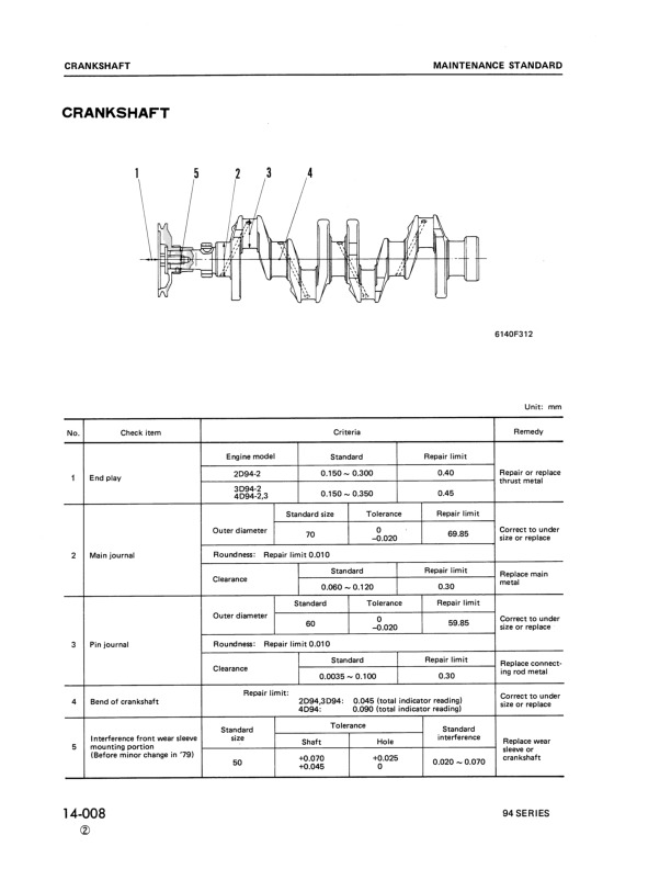
7.7 CRANKSHAFT….96
7.8 GEARS….99
7.9 TROCHOID PUMP….101
8. DISASSEMBLY AND REASSEMBLY….103
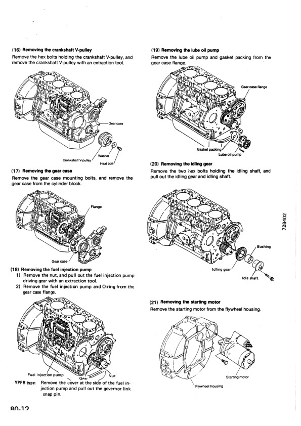
8.1 DISASSEMBLY….104
8.2 PRECAUTIONS BEFORE AND DURING REASSEMBLY….109
9. SERVICE DATA….114
9.1 CYLINDER HEAD….115
9.2 CYLINDER BLOCK….116
9.3 VALVE ROCKER ARM….116
9.4 PISTON….117
9.5 PISTON RING….118
9.6 CONNECTING ROD….119
9.7 CAMSHAFT….119
9.8 CRANKSHAFT….120
9.9 SIDE GAP AND BACKLASH….120
9.10 OTHERS….121
10. TIGHTENING TORQUE….122
10.1 MAIN BOLT/NUT….123
10.2 STANDARD BOLT AND NUT….124
11. FUEL INJECTION PUMP FOR INDIRECT INJECTION SYSTEM….125
11.1 EXPLODED VIEW (YPFR TYPE)….126
11.2 DISASSEMBLY….127
11.3 INSPECTION….129
11.4 REASSEMBLY….131
12. FUEL INJECTION PUMP FOR DIRECT INJECTION SYSTEM….133
12.1 EXPLODED VIEW (YPES TYPE)….134
12.2 SPECIAL SERVICE TOOLS FOR DISASSEMBLY AND REASSEMBLY….136
12.3 DISASSEMBLY….137
12.4 INSPECTION….142
12.5 REASSEMBLY….144
13. GOVERNOR….149
13.1 EXPLODED VIEWS OF GOVERNOR FOR INDIRECT INJECTION SYSTEM….150
13.2 EXPLODED VIEWS OF GOVERNOR FOR DIRECT INJECTION SYSTEM….152
13.3 DISASSEMBLY….154
13.4 INSPECTION….160
13.5 REASSEMBLY….162
14. TURBOCHARGER….166
14.1 SPECIFICATIONS….167
14.2 CONSTRUCTION….168
14.3 WASTE GATE VALVE ADJUSTING METHOD….170
14.4 EXPLODED VIEW OF TURBOCHARGER (WITH WASTE GATE)….172
14.5 TIGHTENING TORQUE….173
14.6 SERVICE STANDARDS….173
15. SERVICE INFORMATION FOR CARB ULG REGULATION….174
15.1 LIMITING THE HIGH IDLE AND LOW IDLE ADJUSTMENT SCREW….175
15.2 LIMITING THE FUEL VOLUME LIMITER SCREW….176
16. ATTACHED DRAWING….177
16.1 EXPLODED VIEWS OF ENGINE COMPONENTS….178
16.2 EXPLODED VIEWS OF ENGINE COMPONENTS….180
20. EPA CERTIFIED ENGINE….182
20.1 APPLICABLE MACHINE, SERIAL NUMBER (EPA CERTIFIED ENGINE)….183
20.2 EPA CERTIFICATION PLATE ATTACHING LOCATION….184
20.3 DIFFERENCES WITH THE CURRENT PRODUCTION MODEL….185
20.4 FUEL INJECTION TIMING ADJUSTMENT….186
20.5 SECIFICATIONS….197
SEBM013001 – 94E, 98E Series Diesel Engine Shop Manual….206
COVER….206
CONTENTS….207
1. GENERAL….212
1.1 SPECIFICATIONS….213
1.2 FUEL OIL, LUBRICATING OIL AND COOLING WATER….215
1.3 ENGINE EXTERNAL VIEWS….217
1.4 STRUCTURAL DESCRIPTION….219
1.5 HOW TO READ THIS MANUAL….221
1.6 PRECAUTIONS FOR SERVICE WORK….223
1.7 TIGHTENING TORQUES FOR STANDARD BOLTS AND NUTS….224
2. TROUBLESHOOTING….225
2.1 QUICK REFERENCE TABLE FOR TROUBLESHOOTING….226
2.2 TROUBLESHOOTING BY MEASURING COMPRESSION PRESSURE….230
3. INSPECTION AND ADJUSTMENT….232
3.1 OIL INSPECTION….233
3.2 COOLING WATER INSPECTION….233
3.3 INSPECTING WATER LEAK FROM COOLING WATER SYSTEM AND RADIATOR….233
3.4 FAN BELT TENSION INSPECTION AND ADJUSTMENT….234
3.5 ADJUSTING THE VALVE CLEARANCE….235
3.6 INSPECTING THE FUEL INJECTION NOZZLE INJECTION PRESSURE AND SPRAY PATTERN….236
3.7 FUEL INJECTION TIMING INSPECTION AND ADJUSTMENT….239
3.8 ADJUSTING THE NO-LOAD MAXIMUM (OR MINIMUM) REVOLUTIONS….240
3.9 SENSOR INSPECTION….241
3.10 BATTERY INSPECTION….242
3.11 ADJUSTING OPERATION….244
3.12 LONG STORAGE….245
3.13 PERIODIC MAINTENANCE SCHEDULE….246
4. ENGINE BODY….248
4.1 INTRODUCTION….249
4.2 CYLINDER HEAD….250
4.3 GEAR TRAIN AND CAMSHAFT….259
4.4 CYLINDER BLOCK….264
5. LUBRICATION SYSTEM….277
5.1 LUBRICATION SYSTEM DIAGRAM….278
5.2 TROCHOID PUMP COMPONENTS….278
5.3 DISASSEMBLY (REVERSE THE PROCEDURE BELOW FOR ASSEMBLY)….279
5.4 SERVICING POINTS….279
5.5 PARTS INSPECTION AND MEASUREMENT….280
6. COOLING SYSTEM….281
6.1 COOLING WATER SYSTEM….282
6.2 COOLING WATER PUMP COMPONENTS….283
6.3 DISASSEMBLY (REVERSE THE PROCEDURE BELOW FOR ASSEMBLY)….283
6.4 SERVICING POINTS….283
7. FUEL INJECTION PUMP/GOVERNOR….284
7.1 INTRODUCTION….285
7.2 FUEL INJECTION PUMP….285
7.3 FUEL INJECTION NOZZLE….292
7.4 FUEL FEED PUMP….292
7.5 GOVERNOR….294
7.6 SPECIAL SERVICE TOOLS FOR DISASSEMBLY/ASSEMBLY….295
8. STARTING MOTOR….297
8.1 SPECIFICATIONS….298
8.2 COMPONENTS….299
8.3 TROUBLESHOOTING….300
8.4 NAMES OF PARTS AND DISASSEMBLY PROCEDURE….301
8.5 INSPECTION AND MAINTENANCE….305
8.6 SERVICE STANDARDS….311
8.7 ASSEMBLY….312
8.8 CHARACTERISTIC TEST….314
9. ALTERNATOR….315
9.1 SPECIFICATIONS….316
9.2 SECTIONAL VIEW….317
9.3 TROUBLESHOOTING….318
9.4 PARTS NAMES AND DISASSEMBLY PROCEDURE….319
9.5 INSPECTION AN OVERHAUL….322
9.6 ASSEMBLY….326
9.7 SERVICE STANDARDS….327
9.8 PERFORMANCE TEST….328
10. SPECIAL SERVICE TOOLS….329
10.1 SPECIAL TOOLS….330
10.2 MEASURING INSTRUMENTS….332
11. SERVICE STANDARDS….335
11.1 ENGINE TUNING….336
11.2 ENGINE BODY….337
11.3 LUBRICATING OIL SYSTEM (TROCHOID PUMP)….341
11.4 TIGHTENING TORQUES FOR MAIN PARTS….342
20. EPA CERTIFIED ENGINE….344
20.1 APPLICABLE MACHINE, SERIAL NUMBER (EPA CERTIFIED ENGINE)….345
SEBM035103 – 82E, 84E, 88E, 94E, 98E Series Diesel Engine Shop Manual….346
COVER….346
CONTENTS….360
1. GENERAL ….361
1.1 SPECIFICATIONS….362
1.2 ENGINE EXTERNAL VIEWS….374
1.3 STRUCTURAL DESCRIPTION ….375
2. INSPECTION ANG ADJUSTMENT….376
2.1 PERIODIC MAINTENANCE SCHEDULE….377
2.2 PERIODIC INSPECTION AND MAINTENANCE PROCEDURE….378
2.2.1 CHECK BEFORE DAILY OPERATION ….378
2.2.2 INSPECTION AFTER INITIAL 50 HOURS OPERATION ….380
2.2.3 INSPECTION EVERY 50 HOURS ….383
2.2.4 INSPECTION EVERY 250 HOURS OR 3 MONTHS ….387
2.2.5 INSPECTION EVERY 500 HOURS OR 6 MONTHS ….390
2.2.6 INSPECTION EVERY 1000 HOURS OR ONE YEAR ….392
2.2.7 INSPECTION EVERY 2000 HOURS OR 2 YEARS ….401
2.3 ADJUSTING THE NO-LOAD MAXIMUM OR MINIMUM SPEED….404
2.4 SENSOR INSPECTION ….404
2.4.1 OIL PRESSURE SWITCH….404
2.4.2 THERMO SWITCH….404
2.5 WATER LEAK CHECK IN COOLING WATER SYSTEM ….405
2.6 RADIATOR CAP INSPECTION ….405
2.7 THERMOSTAT INSPECTION ….406
2.8 ADJUSTING OPERATION ….407
2.9 LONG STORAGE….407
3. TROUBLESHOOTING….408
3.1 PREPARATION BEFORE TROUBLESHOOTING….409
3.2 QUICK REFERENCE TABLE FOR TROUBLESHOOTING ….410
3.3 TROUBLESHOOTING BY MEASURING COMPRESSION PRESSURE….413
4. DISASSEMBLY, INSPECTION AND REASSEMBLY OF ENGINES….415
4.1 COMPLETE DISASSEMBLY AND REASSEMBLY….416
4.1.1 INTRODUCTION ….416
4.1.2 SPECIAL SERVICE TOOLS….417
4.1.3 COMPLETE DISASSEMBLY….422
4.1.4 PRECAUTIONS BEFORE AND DURING REASSEMBLY….426
4.1.5 ADJUSTING OPERATION ….426
4.2 CYLINDER HAED: DISASSEMBLY, INSPECTION AND REASSEMBLY….427
4.2.1 COMPONENTS(2-VALVE CYLINDER HAED)….427
4.2.2 DISASSEMBLY PROCEDURE….427
4.2.3 REASSEMBLY PROCEDURE….428
4.2.4 SERVICING POINTS….429
4.2.5 PARTS INSPECTION AND MEASUREMENT….433
4.2.6 VALVE SEAT CORRECTION ….437
4.2.7 VALVE GUIDE REPLACEMENT….438
4.2.8 VALVE STEM SEAL REPLACEMENT….439
4.3 GEAR TRAIN AND CAMSHAFT….440
4.3.1 COMPONENTS….440
4.3.2 DISASSEMBLY PROCEDURE….440
4.3.3 REASSEMBLY PROCEDURE….440
4.3.4 SERVICING POINTS….441
4.3.5 PARTS INSPECTION AND MEASUREMENT….444
4.3.6 OIL SEAL REPLACEMENT (GEAR CASE SIDE)….446
4.3.7 CAMSHAFT BUSHING REPLACEMENT….446
4.4 CYLINDER BLOCK….447
4.4.1 COMPONENTS….447
4.4.2 DISASSEMBLY PROCEDURE….447
4.4.3 REASSEMBLY PROCEDURE….447
4.4.4 SERVICING POINTS….448
4.4.5 PARTS INSPECTION AND MEASUREMENT….452
4.4.6 CYLINDER BORE CORRECTION ….463
4.4.7 PISTON PIN BUSHING REPLACEMENT….464
4.4.8 OIL SEAL REPLACEMENT (FLYWHEEL HOUSING SIDE)….464
5. LUBRICATION SYSTEM….465
5.1 LUBRICATION SYSTEM DIAGRAM….466
5.2 TROCHOID PUMP COMPONENTS….467
5.3 DISASSEMBLY (REVERSE THE PROCEDURE BELOW FOR ASSEMBLY)….467
5.4 SERVICING POINTS….467
5.5 PARTS INSPECTION AND MEASUREMENT….468
6. COOLING SYSTEM ….470
6.1 COOLING WATER SYSTEM ….471
6.2 COOLING WATER PUMP COMPONENTS….471
6.3 DISASSEMBLY (REVERSE THE PROCEDURE BELOW FOR ASSEMBLY)….472
6.4 SERVICING POINTS….472
7. FUEL INJECTION PUMP/GOVERNOR….473
7.1 INTRODUCTION ….474
7.2 FUEL INJECTION PUMP….474
7.2.1 FUEL SYSTEM DIAGRAM….474
7.2.2 EXTERNAL VIEW AND COMPONENTS….475
7.2.3 DISASSEMBLY PROCEDURE….475
7.2.4 ASSEMBLY PROCEDURE….476
7.2.5 SERVICING POINTS….476
8. TURBOCHARGER….478
8.1 STRUCTURE AND FUNCTIONS….479
8.1.1 MAIN SPECIFICATIONS….479
8.1.2 CONSTRUCTION….479
8.1.3 STRUCTURAL AND FUNCTIONAL OUTLINE….480
8.1.4 COMPONENTS….480
8.1.5 COMPONENTS….481
8.2 SERVICE STANDARDS AND TIGHTENING TORQUE….482
8.2.1 SERVICE STANDARDS….482
8.2.2 TIGHTENING TORQUE….483
8.3 PERIODIC INSPECTION PROCEDURE….484
8.3.1 PERIODIC INSPECTION INTERVALS….484
8.3.2 INSPECTION PROCEDURE….484
8.3.3 WASTE GATE VALVE ADJUSTMENT PROCEDURE….485
8.4 DISASSEMBLY PROCEDURE….487
8.4.1 PREPARATION FOR DISASSEMBLY….487
8.4.2 INSPECTION BEFORE DISASSEMBLY….488
8.4.3 DISASSEMBLY….488
8.5 WASHING AND INSPECTION PROCEDURE….489
8.5.1 WASHING….489
8.5.2 INSPECTION PROCEDURE….490
8.6 REASSEMBLY PROCEDURE….493
8.6.1 PREPARATION FOR REASSEMBLY….493
8.6.2 REASSEMBLY….493
8.7 HANDING AFTER DISASSEMBLY AND REASSEMBLY….496
8.7.1 INSTRUCTIONS FOR TURBOCHARGER INSTALLATION ….496
8.8 TROUBLESHOOTING….497
8.8.1 EXCESSIVELY EXHAUST SMOKE….497
8.8.2 WHITE SMOKE GENERATION ….497
8.8.3 SUDDEN OIL DECREASE….498
8.8.4 DECREASE IN OUTPUT….498
8.8.5 POOR (SLOW) RESPONSE (STARTING) OF TURBOCHARGER….498
8.8.6 ABNORMAL SOUND OR VIBRATION ….498
9. STARTING MOTOR….499
9.1 FOR 4D94LE/(S)4D98E….500
9.1.1 SPECIFICATIONS….500
9.1.2 COMPONENTS….501
9.1.3 TROUBLESHOOTING ….502
9.1.4 NAMES OF PARTS AND DISASSEMBLY PROCEDURE….503
9.1.5 INSPECTION AND MAINTENANCE….507
9.1.6 SERVICE STANDARDS….512
9.1.7 ASSEMBLY….513
9.1.8 CHARACTERISTIC TEST….515
10. ALTERNATOR….516
10.1 THE 40A ALTERNATOR FOR 3D84E AND OTHER MODELS….517
10.1.1 COMPONENTS….517
10.1.2 SPECIFICATIONS….518
10.1.3 WIRING DIAGRAM….518
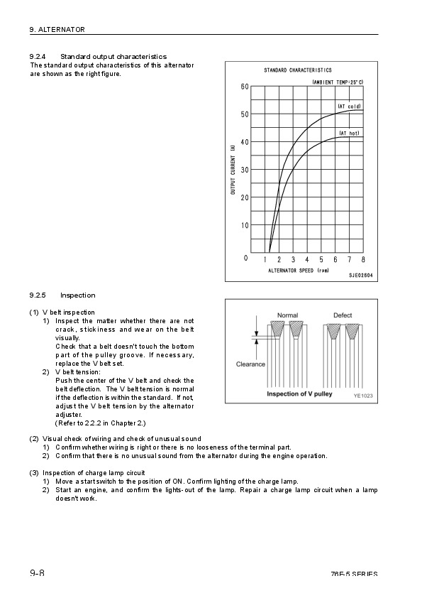
10.1.4 STANDARD OUTPUT CHARACTERISTICS….519
10.1.5 INSPECTION ….519
10.1.6 TROUBLESHOOTING….520
11. ELECTRIC WIRING….521
11.1 ELECTRIC WIRING DIAGRAM….522
11.2 PRECAUTION ON ELECTRIC WIRING….524
11.2.1 ALTERNATOR….524
11.2.2 STARTING MOTOR….525
11.2.3 CURRENT LIMITER….526
11.2.4 SECTION AREA AND RESISTANCE OF ELECTRIC WIRE….527
12. SERVICE STANDARDS….528
12.1 ENGINE TUNING….529
12.2 ENGINE BODY….530
12.2.1 CYLINDER HEAD ….530
12.2.2 GEAR TRAIN AND CAMSHAFT….533
12.2.3 CYLINDER BLOCK….534
12.3 LUBRICATING OIL SYSTEM (TROCHOID PUMP)….539
13. TIGHTENING TORQUE FOR BOLTS AND NUTS….540
13.1 TIGHTENING TORQUES FOR MAIN BOLTS AND NUTS….541
13.2 TIGHTENING TORQUES FOR STANDARD BOLTS AND NUTS….542
SEN04211-03 – 82E-6, 84E-6, 88E-6, 94E-6, 98E-6 Series Diesel Engine Shop Manual….543
COVER….543
00 Index and foreword….544
Index….544
Composition of shop manual….545
Table of contents….546
Foreword and general information….550
Introduction….551
Applicable machine model and serial number….552
Safety Statements….553
Safety Precautions….554
01 Specification….576
Specification and technical data….576
Component identification….578
Function of major engine components….580
Main electronic control components and features….581
Function of cooling system components….583
Diesel fuel….584
Diesel fuel specifications….584
Filling the fuel tank….585
Priming the fuel system….587
Engine oil….587
Engine oil specifications….587
Engine oil viscosity….588
Checking engine oil….588
Adding engine oil….589
Engine oil capacity (typical)….589
Engine coolant….590
Engine coolant specifications….591
Filling radiator with engine coolant….591
Engine coolant capacity (typical)….592
Specifications….593
Description of Model Number….593
Engine speed specifications….593
Engine general specifications….594
Principal engine specifications….595
3D82AE (– EPA Tier2)….595
3D84E (– EPA Tier2)….596
S3D84E (– EPA Tier2)….597
3D88E (– EPA Tier2)….598
4D84E (– EPA Tier2)….599
S4D84E (– EPA Tier2)….600
4D88E (– EPA Tier2)….601
4D94LE (– EPA Tier2)….602
4D98E (– EPA Tier2)….603
S4D98E (– EPA Tier2)….604
3D82AE-B (complies with EPA Interim Tier4)….605
S3D84E-B (complies with EPA Interim Tier4)….606
3D88E-U (complies with EPA Interim Tier4)….607
3D88E-B (complies with EPA Interim Tier4)….608
S4D84E-Z (complies with EPA Interim Tier4)….609
4D88E-U (complies with EPA Interim Tier4)….610
4D88E-B (complies with EPA Interim Tier4)….611
4D98E-E (complies with EPA Interim Tier4)….612
4D98E-Z (complies with EPA Interim Tier4)….613
S4D98E-Z (complies with EPA Tier3)….614
Engine service standards….615
Tightening torques for standard bolts and nuts….616
Abbreviations and symbols….618
Abbreviations….618
Symbols….618
Unit conversions….619
Unit prefixes….619
Units of length….619
Units of volume….619
Units of mass….619
Units of force….619
Units of torque….619
Units of pressure….619
Units of power….619
Units of temperature….619
30 Testing and adjusting….622
Testing and adjusting, Part 1….622
Before you begin servicing….624
Introduction….637
The importance of periodic maintenance….637
Performing periodic maintenance….637
Komatsu replacement parts….637
Required EPA / ARB maintenance – USA only….637
EPA / ARB installation requirements – USA only….637
Periodic maintenance schedule….638
Periodic maintenance procedures….641
After initial 50 hours of operation….641
Every 50 hours of operation….645
Every 250 hours of operation….648
Every 500 hours of operation….653
Every 1000 hours of operation….657
Every 1500 hours of operation….660
Every 2000 hours of operation….662
Testing and adjusting, Part 2….664
Before you begin servicing….666
Introduction….669
Cylinder head specifications….669
Adjustment specifications….669
Cylinder head….669
Intake / exhaust valve and guide….670
Push rod….672
Rocker arm and shaft….672
Valve spring….673
Camshaft and timing gear train specifications….674
Camshaft….674
Idler gear shaft and bushing….676
Timing gear backlash….676
Crankshaft and piston specifications….677
Crankshaft….677
Thrust bearing….678
Piston….679
Piston ring….681
Connecting rod….684
Tappet….685
Cylinder block specifications….686
Cylinder block….686
Special torque chart….687
Torque for bolts and nuts….687
Special service tools….690
Measuring instruments….694
2-valve cylinder head….696
2-valve cylinder head components….696
Components of a two-valve cylinder head….697
Disassembly of 2-valve cylinder head….698
Cleaning of cylinder head components….702
Inspection of cylinder head components….702
Reassembly of cylinder head….706
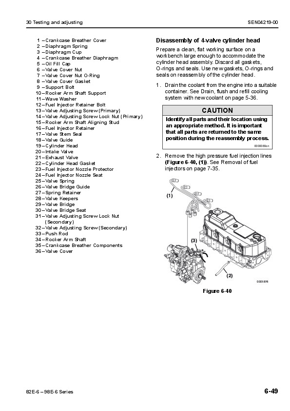
4-valve cylinder head….711
4-valve cylinder head components….711
Disassembly of 4-valve cylinder head….712
Cleaning of cylinder head components….717
Inspection of cylinder head components….718
Reassembly of cylinder head….723
Measuring and adjusting valve clearance….728
2-valve cylinder heads….729
4-valve cylinder heads….730
Crankshaft and camshaft components….733
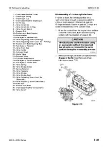
Disassembly of engine….734
Disassembly of camshaft and timing components….735
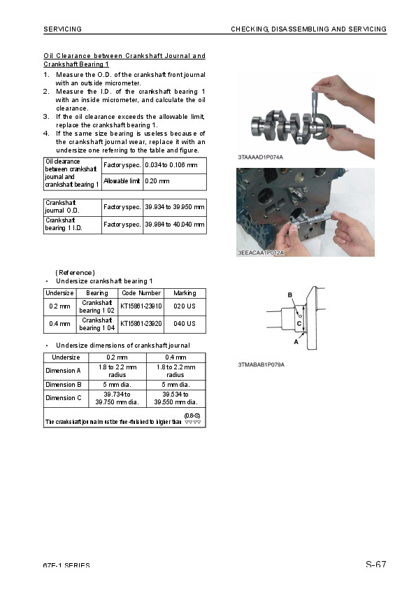
Disassembly of crankshaft and piston components….740
Inspection of crankshaft and camshaft components….744
Honing and boring….750
Reassembly of crankshaft and piston components….751
Reassembly of camshaft and timing components….756
Final reassembly of engine….760
EGR system….761
EGR system….761
EGR system….763
Inspecting/cleaning EGR related components….766
Testing and adjusting, Part 3….772
Before you begin servicing….774
Introduction….779
Fuel injection pump….779
Stop solenoid….780
Cold start device….780
Trochoid fuel pump….781
Electronically controlled governor….781
Fuel system specifications….782
Special torque chart….782
Test and adjustment specifications….783
Special service tools….784
Measuring instruments….784
Fuel system diagram….785
Fuel system components….786
2-valve cylinder head….786
4-valve cylinder head….788
Fuel injection pump….790
Removal of fuel injection pump….790
Installation of fuel injection pump….795
Checking and adjusting fuel injection timing….801
Determining the fuel injection timing specification….801
Checking fuel injection timing….802
Adjusting fuel injection timing….805
Fuel injectors….806
Removal of fuel injectors….806
Testing of fuel injectors….809
Disassembly and inspection of fuel injectors….810
Adjusting fuel injector pressure….812
Reassembly of fuel injectors….812
Installation of the fuel injectors….813
Testing and adjusting, Part 4….816
Before you begin servicing….818
Introduction….821
Cooling system diagram….821
Engine coolant pump components….822
Engine coolant system check….823
Engine coolant pump….823
Removal of engine coolant pump….823
Disassembly of engine coolant pump….825
Cleaning and inspection….825
Reassembly of engine coolant pump….826
Installation of engine coolant pump….827
Testing and adjusting, Part 5….830
Before you begin servicing….832
Introduction….834
Oil pump service information….834
Lubrication system diagram….837
Checking engine oil pressure….838
Trochoid oil pump….838
3D82AE to 4D88E oil pump components….838
Disassembly of oil pump….839
Cleaning and inspection….840
Reassembly of oil pump….841
Trochoid oil pump….842
3D82AE-B, 3D88E-B, 3D88E-U, 4D88E-B, 4D88E-U, S3D84E-Z, S4D84E-Z Oil pump components….842
Disassembly of oil pump….843
Cleaning and inspection….843
Reassembly of oil pump….845
Trochoid oil pump….846
4D94LE/98E oil pump components….846
Disassembly of oil pump….846
Cleaning and inspection….847
Reassembly of oil pump….848
Testing and adjusting, Part 6….850
Before you begin servicing….852
Introduction….854
Specifications….854
Turbocharger service information….854
Troubleshooting….855
Excessive exhaust smoke….855
Generates white smoke….856
Sudden oil decrease….856
Decrease in output….856
Poor (slow) response (starting) of turbocharger….856
Abnormal sound or vibration….856
Turbocharger components….857
Turbocharger component functions….859
Theory of operation….860
Compressor side sealing mechanism….860
Waste gate modulation….860
Washing procedure….861
Periodic inspection….862
Visual inspection….862
Inspection of rotor rotation….862
Inspection of rotor play….862
Removal of turbocharger….862
Checking rotor play….863
Waste gate valve test….863
Waste gate actuator leak test….864
Installation of turbocharger….864
Testing and adjusting, Part 7….866
Before you begin servicing….868
Introduction….870
Starter motor information….870
3D82AE to 4D88E – Standard and optional….870
4D94LE to S4D98E – Standard and optional….871
Starter motor specifications….872
Starter motor troubleshooting….873
Starter motor components….874
Starter motor….875
Removal of starter motor….875
Disassembly of starter motor….875
Cleaning and inspection….877
Reassembly of starter motor….882
Check pinion projection length….883
No-load test….884
Installation of starter motor….885
Testing and adjusting, Part 8….888
Before you begin servicing….890
Introduction….893
Dynamo and alternator information….893
3D82AE to S4D98E – Standard and optional dynamos….893
3D82AE to S4D98E – Standard and optional alternators….893
Alternator specifications….894
Dynamo specifications….894
Alternator troubleshooting….895
Alternator components….896
Alternator wiring diagram….897
Alternator standard output….898
Alternator….899
Removal of alternator….899
Disassembly of alternator….899
Reassembly of alternator….901
Installation of alternator….903
Dynamo component location….904
Dynamo wiring diagram….905
Operation of dynamo….905
Dynamo standard output….906
Testing of dynamo….907
Testing stator coil continuity….907
Testing stator coil short-to-ground….907
Testing dynamo regulated output….907
Dynamo….907
Removal of dynamo….907
Disassembly of dynamo….908
Reassembly of dynamo….908
Installation of dynamo….909
40 Troubleshooting….912
Troubleshooting of mechanical system….912
Special service tools….914
Troubleshooting by measuring compression pressure….916
Compression pressure measurement method….916
Quick reference table for troubleshooting….919
Failure Diagnostic List….920
Komatsu 68E, 74E, 78E, 82E, 84E, 88E, 94E, 98E Series Diesel Engine Repair Service Manuals
INSTANT DOWNLOAD