Complete service repair manual with Electrical Wiring Diagrams for Komatsu Hydraulic Excavator PC210-8, PC210LC-8, PC210NLC-8, PC230NHD-8, PC240LC-8, PC240NLC-8, with all the technical information to maintain, diagnose, repair, rebuild like professional mechanics.
Komatsu Hydraulic Excavator PC210-8, PC210LC-8, PC210NLC-8, PC230NHD-8, PC240LC-8, PC240NLC-8 workshop service repair manual includes:
* Numbered table of contents easy to use so that you can find the information you need fast.
* Detailed sub-steps expand on repair procedure information
* Numbered instructions guide you through every repair procedure step by step.
* Troubleshooting and electrical service procedures are combined with detailed wiring diagrams for ease of use.
* Notes, cautions and warnings throughout each chapter pinpoint critical information.
* Bold figure number help you quickly match illustrations with instructions.
* Detailed illustrations, drawings and photos guide you through every procedure.
* Enlarged inset helps you identify and examine parts in detail.
UEN00084-07 – Hydraulic Excavator PC210-8, PC210LC-8, PC210NLC-8, PC230NHD-8, PC240LC-8, PC240NLC-8 Shop Manual.pdf
UEN00084 – Hydraulic Excavator PC210-8, PC210LC-8, PC210NLC-8, PC230NHD-8, PC240LC-8, PC240NLC-8 Shop Manual.pdf
SEAM02050307 – Hydraulic Excavator PC200-3, PC210-3, PC220-3, PC240-3, PC280-3 Operation & Maintenance Manual.pdf
UEAM004904 – Hydraulic Excavator PC210-8, PC210LC-8, PC210NLC-8, PC230NHD-8, PC240LC-8, PC240NLC-8 Operation & Maintenance Manual.pdf
UEAM004912 – Hydraulic Excavator PC210-8, PC210LC-8, PC210NLC-8, PC230NHD-8, PC240LC-8, PC240NLC-8 Operation & Maintenance Manual.pdf
PRODUCT DETAILS:
Total Pages: 3,330 pages
File Format: PDF
Language: English
SEAM02050307 – Hydraulic Excavator PC200-3, PC210-3, PC220-3, PC240-3, PC280-3 Operation & Maintenance Manual…2
UEAM004904 – Hydraulic Excavator PC210-8, PC210LC-8, PC210NLC-8, PC230NHD-8, PC240LC-8, PC240NLC-8 Operation & Maintenance Manual…83
FOREWORD…85
FOREWORD…86
SAFETY INFORMATION…87
NOISE (PC210,210LC,210NLC, PC230NHD)…89
NOISE (PC240LC,240NLC)…90
Vibration levels…91
Guide to Reduce Vibration Levels on Machine…91
INTRODUCTION…93
DIRECTIONS OF MACHINE…93
BREAKING-IN THE NEW MACHINE…94
PRODUCT INFORMATION…95
PRODUCT IDENTIFICATION NUMBER (PIN)/MACHINE SERIAL NO. PLATE…95
ENGINE SERIAL NUMBER PLATE AND ITS LOCATION…95
SERVICE METER LOCATION…96
TABLE TO ENTER SERIAL NO. AND DISTRIBUTOR…96
MACHINE SERIAL PLATES…97
STANDARD SERIAL PLATE…97
FOREWORD…98
SAFETY…98
OPERATION…100
MAINTENANCE…102
SPECIFICATIONS…104
ATTACHMENTS AND OPTIONS…105
SUPER LONG FRONT BOOM AND ARM PC210/240-8…107
INDEX…108
COLOPHON…108
SAFETY…109
SAFETY INFORMATION…110
SAFETY LABELS…112
LOCATION OF SAFETY LABELS…112
SAFETY LABELS…113
SAFETY INFORMATION…120
SAFETY RULES…120
IF PROBLEMS ARE FOUND…120
WORKING WEAR AND PERSONAL PROTECTIVE ITEMS…120
FIRE EXTINGUISHER AND FIRST AID KIT…120
SAFETY EQUIPMENT…121
KEEP MACHINE CLEAN…121
KEEP OPERATOR'S COMPARTMENT CLEAN…121
LEAVING OPERATOR'S SEAT WITH LOCK…121
HANDRAILS AND STEPS…122
MOUNTING AND DISMOUNTING…123
NO PERSONS ON ATTACHMENTS…123
DO NOT GET CAUGHT IN ARTICULATED PORTION…123
BURN PREVENTION…123
ACTION IF FIRE OCCURS…125
WINDSHIELD WASHER FLUID…125
FALLING OBJECTS, FLYING OBJECTS AND INTRUDING OBJECTS PREVENTION…125
ATTACHMENT INSTALLATION…125
ATTACHMENT COMBINATIONS…126
CAB WINDOW GLASSES…126
UNAUTHORIZED MODIFICATIONS…126
SAFETY AT JOBSITE…126
WORKING ON LOOSE GROUND…126
DISTANCE TO HIGH VOLTAGE CABLES…127
ENSURE GOOD VISIBILITY…127
VENTILATION FOR ENCLOSED AREA…128
SIGNALMAN'S SIGNAL AND SIGNS…128
EMERGENCY EXIT FROM OPERATOR'S CAB…128
ELECTROMAGNETIC INTERFERENCE…128
ASBESTOS DUST HAZARD PREVENTION…129
SAFETY MACHINE OPERATION…130
STARTING ENGINE…130
CHECKS BEFORE STARTING ENGINE…130
SAFETY RULES FOR STARTING ENGINE…131
STARTING ENGINE IN COLD WEATHER…131
OPERATION…132
CHECKS BEFORE OPERATION…132
SAFETY RULES FOR CHANGING MACHINE DIRECTIONS…132
SAFETY RULES FOR TRAVELLING…133
TRAVELLING ON SLOPES…134
OPERATIONS ON SLOPES…135
PROHIBITED OPERATIONS…135
OPERATIONS ON SNOW…137
PARKING MACHINE…137
TRANSPORTATION…138
LOADING AND UNLOADING…138
SHIPPING THE MACHINE…139
BATTERY…140
STARTING ENGINE WITH BOOSTER CABLES…141
TOWING…142
SAFETY RULES FOR TOWING…142
LIFTING OBJECTS WITH BUCKET…143
SAFETY RULES FOR LIFTING OBJECTS…143
SAFETY MAINTENANCE INFORMATION…144
WARNING TAG…144
KEEP WORK PLACE CLEAN AND TIDY…144
APPOINT LEADER WHEN WORKING WITH OTHERS…144
STOP ENGINE BEFORE CARRYING OUT MAINTENANCE…145
TWO WORKERS FOR MAINTENANCE WHEN ENGINE IS RUNNING…146
PROPER TOOLS…146
ACCUMULATOR…147
HANDLING GAS SPRING…147
PERSONNEL…148
ATTACHMENTS…148
WORK UNDER THE MACHINE…148
NOISE…149
WHEN USING HAMMER…149
WELDING WORKS…149
REMOVING BATTERY TERMINALS…149
SAFETY FIRST WHEN USING HIGH-PRESSURE GREASE TO ADJUST TRACK TENSION…150
DO NOT DISASSEMBLE RECOIL SPRINGS…150
SAFETY RULES FOR HIGH-PRESSURE OIL…150
OPERATION…153
MACHINE VIEW ILLUSTRATIONS…154
OVERALL MACHINE VIEW…154
CONTROLS AND GAUGES…155
DETAILED CONTROLS AND GAUGES…156
MONITORING SYSTEM…156
Basic Operation of Machine Monitor…157
Basic Check Monitors…161
Caution Monitors…163
Emergency Monitors…166
Meter Display Portion…168
Monitor Switches Portion…175
Handling Function Switches…184
SWITCHES…220
CONTROL LEVERS AND PEDALS…225
CEILING WINDOW…228
WINDSHIELD…228
EMERGENCY ESCAPE HAMMER…234
DOOR LOCK…234
CAP WITH LOCK…235
DRINK BOX…237
MAGAZINE BOX…237
ASHTRAY…237
AIR CONDITIONER CONTROLS…238
Air Conditioner Control Panel…238
Method of Operation…243
Use Air Conditioner with Care…250
Air Conditioner Maintenance…250
RADIO…251
Control Panel…251
Controls of Radio…253
Use Radio with Care…255
Space for radio cassette…255
AUXILIARY ELECTRIC POWER…256
24V power source…256
12V power source…256
FUSE…257
FUSIBLE LINK…258
CONTROLLER…258
TOOL BOX…258
GREASE GUN HOLDER…258
MACHINE OPERATIONS AND CONTROLS…259
BEFORE STARTING ENGINE…259
Walk-around Checks…259
REFUELLING PUMP…260
Checks Before Starting…261
Adjustment…268
Seat Belt…272
Operations Before Starting Engine…273
STARTING ENGINE…275
AFTER STARTING ENGINE…278
Warming Up Engine…279
Warming Up Hydraulic Equipment…281
Operation After Completion Of Warming-Up Operation…287
STOPPING THE ENGINE…289
MACHINE OPERATION…290
Preparations for Moving the Machine…290
Moving Machine Forward…291
Moving Machine Backward…292
Stopping Machine…293
STEERING THE MACHINE…294
Steering…294
SWINGING…296
WORK EQUIPMENT CONTROLS AND OPERATIONS…297
WORKING MODE…299
PROHIBITED OPERATIONS…301
GENERAL OPERATION INFORMATION…303
TRAVELLING ON SLOPES…305
ESCAPE FROM MUD…307
Track on One Side Stuck…307
Tracks on Both Sides Stuck…307
RECOMMENDED APPLICATIONS…308
Backhoe Work…308
Shovel Work…308
Ditching Work…308
Loading Work…309
BUCKET REPLACEMENT AND INVERSION…310
Replacement…310
Inversion…312
PARKING MACHINE…313
CHECK AFTER SHUT OFF ENGINE…315
MACHINE INSPECTION AFTER DAILY WORK…315
LOCKING…315
TRANSPORTATION…316
TRANSPORTATION PROCEDURE…316
SPECIAL TRANSPORTATION INSTRUCTIONS FOR PC210NLC-8 AND PC230NHD-8…316
LOADING AND UNLOADING WITH TRAILER…318
Loading…319
Securing Machine…322
Unloading…326
LIFTING MACHINE…328
COLD WEATHER OPERATION…330
COLD WEATHER OPERATION INFORMATION…330
Fuel and Lubricants…330
Cooling System Coolant…330
Battery…331
AFTER DAILY WORK COMPLETION…332
AFTER COLD WEATHER SEASON…332
LONG TERM STORAGE…333
BEFORE STORAGE…333
DURING STORAGE…333
AFTER STORAGE…334
STARTING MACHINE AFTER LONG-TERM STORAGE…334
TROUBLES AND ACTIONS…335
RUNNING OUT OF FUEL…335
PHENOMENA THAT ARE NOT FAILURES…335
TOWING THE MACHINE…336
LIGHTWEIGHT TOWING HOLE…337
SEVERE JOB CONDITION…337
DISCHARGED BATTERY…338
Battery Removal and Installation…338
Battery Charges…339
Starting Engine with Booster Cables…340
OTHER TROUBLE…342
Electrical System…342
Chassis…343
Engine…344
Electronic Control System…346
Point of Contact to Telephone when Error Occurs…346
MAINTENANCE…347
MAINTENANCE INFORMATION…348
OUTLINE OF SERVICE…351
HANDLING OIL, FUEL, COOLANT, AND PERFORMING OIL CLINIC…351
OIL…351
FUEL…352
COOLANT AND WATER FOR DILUTION…352
GREASE…353
CARRYING OUT KOWA (Komatsu Oil Wear Analysis)…353
STORING OIL AND FUEL…354
FILTERS…354
EXPLANATION OF LUBRICATION CHART DECAL…355
ELECTRIC SYSTEM MAINTENANCE…357
WEAR PARTS…358
WEAR PARTS LIST…358
RECOMMENDED FUEL, COOLANT, AND LUBRICANT…359
RECOMMENDED BRANDS, RECOMMENDED QUALITY FOR PRODUCTS OTHER THAN KOMATSU GENUINE OIL…361
TIGHTENING TORQUE SPECIFICATIONS…362
TIGHTENING TORQUE LIST…362
SAFETY CRITICAL PARTS…363
SAFETY CRITICAL PARTS LIST…363
MAINTENANCE SCHEDULE…364
MAINTENANCE SCHEDULE CHART…364
MAINTENANCE INTERVAL FOR HYDRAULIC BREAKER…366
MAINTENANCE PROCEDURE…367
INITIAL 250 HOURS MAINTENANCE (ONLY AFTER THE FIRST 250 HOURS)…367
INITIAL 500 HOURS MAINTENANCE (ONLY AFTER THE FIRST 500 HOURS)…367
WHEN REQUIRED…368
CHECK, CLEAN AND REPLACE AIR CLEANER ELEMENT…368
CLEAN INSIDE OF COOLING SYSTEM…373
CHECK AND TIGHTEN TRACK SHOE BOLTS…376
CHECK AND ADJUST TRACK TENSION…377
REPLACE BUCKET TEETH (VERTICAL PIN TYPE)…379
REPLACE BUCKET TEETH (HORIZONTAL PIN TYPE)…382
ADJUST BUCKET CLEARANCE…383
CHECK WINDOW WASHER FLUID LEVEL, ADD FLUID…384
CHECK AND MAINTENANCE AIR CONDITIONER…385
WASH WASHABLE FLOOR…386
BLEEDING AIR FROM HYDRAULIC SYSTEM…389
CHECK BEFORE STARTING…391
EVERY 100 HOURS MAINTENANCE…392
LUBRICATING…392
EVERY 250 HOURS MAINTENANCE…394
CHECK LEVEL OF BATTERY ELECTROLYTE…394
CHECK AIR CONDITIONER COMPRESSOR BELT TENSION, ADJUST…396
EVERY 500 HOURS MAINTENANCE…397
LUBRICATING…397
LUBRICATE SWING CIRCLE…398
CHANGE OIL IN ENGINE OIL PAN, REPLACE ENGINE OIL FILTER CARTRIDGE…399
REPLACE FUEL PRE-FILTER CARTRIDGE…401
CHECK SWING PINION GREASE LEVEL, ADD GREASE…403
CLEAN AND INSPECT RADIATOR FINS, OIL COOLER FINS, AFTERCOOLER FINS, FUEL COOLER FINS, AND CONDENSER FINS (ONLY MACHINES EQUIPPED WITH AIR CONDITIONER)…404
CLEAN AIR CONDITIONER FRESH/RECIRC FILTERS…406
REPLACE BREATHER ELEMENT IN HYDRAULIC TANK…407
CHECK OIL LEVEL IN SWING MACHINERY CASE, ADD OIL…408
CHECK OIL LEVEL IN FINAL DRIVE CASE, ADD OIL…409
EVERY 1000 HOURS MAINTENANCE…410
REPLACE HYDRAULIC OIL FILTER ELEMENT…410
CHANGE OIL IN SWING MACHINERY CASE…411
CHECK OIL LEVEL IN DAMPER CASE, ADD OIL…412
REPLACE FUEL MAIN FILTER CARTRIDGE…413
CHECK ALL TIGHTENING POINTS OF ENGINE EXHAUST PIPE CLAMPS…414
REPLACE CORROSION RESISTOR CARTRIDGE…415
CHECK FAN BELT TENSION AND REPLACE FAN BELT…415
CHECK NITROGEN GAS CHARGE PRESSURE IN ACCUMULATOR (for breaker)…415
EVERY 2000 HOURS MAINTENANCE…416
CHANGE OIL IN FINAL DRIVE CASE…416
CLEAN HYDRAULIC TANK STRAINER…417
CHECKING CHARGE PRESSURE OF NITROGEN GAS IN ACCUMULATOR (FOR CONTROL CIRCUIT)…418
CHECK ALTERNATOR, STARTING MOTOR…421
CHECK ENGINE VALVE CLEARANCE, ADJUST…421
EVERY 4000 HOURS MAINTENANCE…422
CHECK WATER PUMP…422
CHECK VIBRATION DAMPER…422
REPLACE ACCUMULATOR (FOR CONTROL CIRCUIT)…423
CHECK FOR LOOSENESS OF HIGH-PRESSURE PIPING CLAMP, HARDENING OF RUBBER…424
CHECK FOR MISSING FUEL SPRAY PREVENTION CAP, HARDENING OF RUBBER…424
CHECK OPERATING CONDITION OF COMPRESSOR…425
EVERY 5000 HOURS MAINTENANCE…426
CHANGE OIL IN HYDRAULIC TANK…426
EVERY 8000 HOURS MAINTENANCE…427
REPLACE FUEL SPRAY PREVENTION CAP…427
REPLACE HIGH-PRESSURE PIPING CLAMP…427
SPECIFICATIONS…429
SPECIFICATIONS…430
MONOBOOM WORKING RANGE…432
PC210-8 WORKING RANGE (2-PIECE BOOM)…434
PC230-8 WORKING RANGE (2-PIECE BOOM)…434
PC240-8 WORKING RANGE (2-PIECE BOOM)…434
EXPLANATION OF LIFTING CAPACITY CHART PC210, PC210LC, PC210NLC, PC230NHD-8…436
PC210-8…437
PC210LC-8…438
PC210NLC-8…439
PC230NHD-8…440
EXPLANATION OF LIFTING CAPACITY CHART PC240LC, PC240NLC-8…441
PC240LC-8…442
PC240NLC-8…443
EXPLANATION OF LIFTING CAPACITY CHART PC210, PC210LC, PC210NLC-8, pc230nhd-8 2 PIECE BOOM…444
PC210-8…445
PC210LC-8…446
PC210NLC-8…447
PC230NHD-8…448
EXPLANATION OF LIFTING CAPACITY CHART (PC240LC,NLC-8 2 PIECE BOOM)…449
PC240LC-8, PC240NLC-8 2 PIECE BOOM…450
ATTACHMENTS AND OPTIONS…453
GENERAL PRECAUTIONS FOR SAFETY…454
PRECAUTIONS WHEN SELECTING…454
READ THE INSTRUCTION MANUAL THOROUGHLY…454
PRECAUTIONS WHEN REMOVING OR INSTALLING…454
PRECAUTIONS WHEN USING…455
HYDRAULIC QUICK COUPLER PIPING…456
LOCATIONS…456
OPERATION…457
BUCKET WITH HOOK…459
HOOK CONDITION…459
PROHIBITED OPERATIONS…459
MACHINE READY FOR ATTACHMENT…460
LOCATIONS…460
HYDRAULIC CIRCUIT…465
Switching Hydraulic Circuit…465
Adjusting Oil Flow…465
Switching Between Breaker and General Attachment…465
Hydraulic Circuit Connection…466
Oil Flow Path…467
Replace Additional Breaker Filter Element…468
Replace Additional Breaker Pilot Filter Element…470
ATTACHMENT REMOVAL AND INSTALLATION…472
Attachment Removal…472
Attachment Installation…474
ATTACHMENT OPERATIONS…476
When Using Breaker…476
When Using General Attachment Such as Crusher…478
LONG TERM STORAGE…479
SPECIFICATIONS…479
ATTACHMENT GUIDE…480
COMBINATIONS OF WORK EQUIPMENT…480
SELECTION OF TRACK SHOES…483
METHOD OF SELECTING SHOES…483
SELECTION OF BUCKET TEETH…484
METHOD OF SELECTING TEETH…484
STANDARDS FOR SELECTING VERTICAL PIN TYPE AND HORIZONTAL PIN TYPE TEETH…484
HANDLING OF RUBBER PAD SHOE AND ROAD LINER…485
Working Environment…485
Working Conditions…485
Storage and Maintenance…486
Extent of Damage to Rubber…486
Check Road Liner…486
Replace Road Liner…486
TRAPEZOIDAL BUCKET…487
HANDLING EXTENSION ARM…488
HANDLING CLAMSHELL BUCKET…489
CONTROLS (AUXILIARY HYDRAULIC CIRCUITS)…490
CRUSHER CONTROL PEDAL FOR OPENING AND CLOSING…491
CRUSHER CONTROL PEDAL FOR ROTATION…492
RECOMMENDED ATTACHMENT OPERATIONS…493
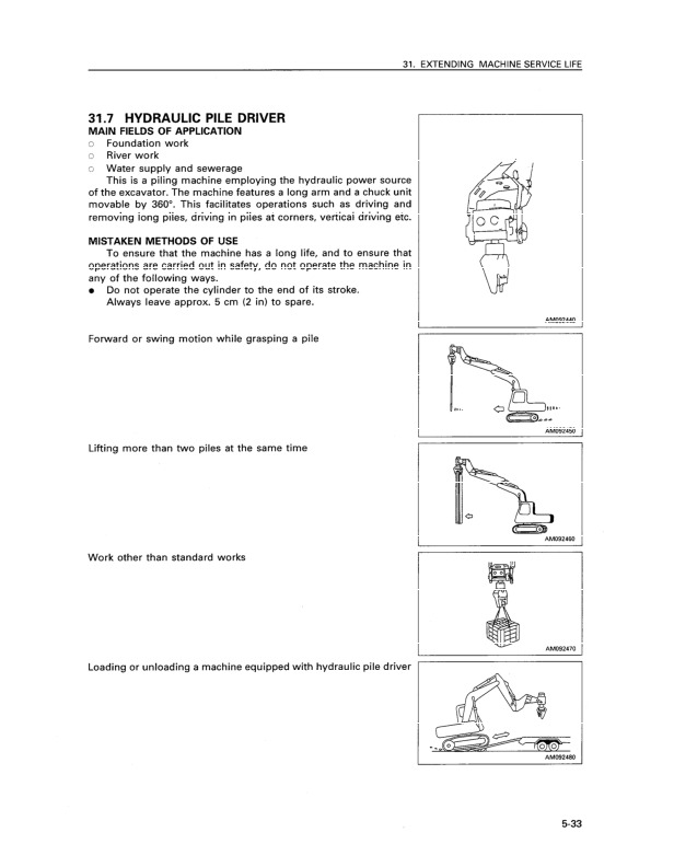
HYDRAULIC BREAKER…493
PC210/230-8 2-PC BOOM…498
FEATURES OF 2-PIECE BOOM & ARM…498
OPERATION…498
BEFORE STORAGE POSTURE WHEN LEAVING MACHINE…500
Lifting…500
TESTING AND ADJUSTING…501
PERODIC MAINTENANCE…501
TRANSPORTATION…502
LUBRICATING…503
Every 500 Hours…503
PC240-8 2-PC BOOM…504
FEATURES OF 2-PIECE BOOM & ARM…504
OPERATION…505
TESTING AND ADJUSTING…507
TRANSPORTATION…508
PC240-8 STRAIGHT BOOM…509
GENERAL VIEW OF MACHINE…509
CAUTION ITEMS…509
CONTROL (AUXILIARY HYDRAULIC CIRCUITS)…510
CRUSHER CONTROL PEDAL FOR OPENING AND CLOSING…511
CRUSHER CONTROL BUTTON FOR ROTATION…512
CEILING WINDOW WIPER SWITCH (3)…513
WORKING RANGE (PC 240 STRAIGHT BOOM)…514
TRANSPORTATION (Straight Boom equipment)…515
HANDLING MACHINES EQUIPPED WITH KOMTRAX…516
BASIC PRECAUTIONS…516
SUPER LONG FRONT BOOM AND ARM PC210/240-8…517
OPERATION INSTRUCTION FOR SUPER LONG FRONT BOOM AND ARM…518
WORKING MODES…519
CHECKS BEFORE STARTING…520
USING SUPER LONG FRONT…521
METHOD OF WORK…522
WHEN TRAVELLING…522
CONTROL LEVERS, PEDALS…523
‘WEEDCUTTER’ MACHINE CONTROL LEVERS, PEDALS…526
RIGHT CONTROL LEVER BUTTONS (5 & 6)…526
LEFT WORK EQUIPMENT CONTROL LEVER (7 & 8)…527
ATTACHMENT FLOW SELECTOR (9)…528
TRANSPORT & STORAGE OF SUPER LONG FRONT MACHINE…529
INSTALLATION OF SUPPORTING LINK…529
TRANSPORTATION OF SUPER LONG FRONT MACHINE…530
WORKING RANGE OF SUPER LONG FRONT…531
LIFTING CAPACITY PC210 LC 15 m SUPER LONG FRONT…532
LIFTING CAPACITY PC210 NLC 15 m SUPER LONG FRONT…533
LIFTING CAPACITY PC240 LC 18 m SUPER LONG FRONT…534
LIFTING CAPACITY PC240 NLC 18 m SUPER LONG FRONT…535
MAINTENANCE…536
SPECIAL SERVICE REQUIREMENTS FOR SUPER LONG FRONT WORK EQUIPMENT…536
EVERY 50 HOURS SERVICE…537
LUBRICATING…537
EVERY 100 HOURS SERVICE…538
LUBRICATING…538
INDEX…541
Numerics…543
<A>…543
<B>…543
<C>…543
<D>…543
<E>…543
<F>…543
<G>…543
<H>…543
<I>…543
<K>…543
<L>…543
<M>…543
<N>…544
<O>…544
<P>…544
<R>…544
<S>…544
<T>…544
<V>…544
<W>…544
<Y>…544
COLOPHON…545
UEAM004912 – Hydraulic Excavator PC210-8, PC210LC-8, PC210NLC-8, PC230NHD-8, PC240LC-8, PC240NLC-8 Operation & Maintenance Manual…547
FOREWORD…549
FOREWORD…550
SAFETY INFORMATION…551
NOISE (PC210,210LC,210NLC, PC230NHD)…553
NOISE (PC240LC,240NLC)…554
Vibration levels…555
Guide to Reduce Vibration Levels on Machine…555
INTRODUCTION…557
DIRECTIONS OF MACHINE…557
OPERATOR PROTECTIVE STRUCTURE…557
VISIBILITY FOR OPERATOR…557
BREAKING-IN THE NEW MACHINE…558
PRODUCT INFORMATION…559
PRODUCT IDENTIFICATION NUMBER (PIN)/MACHINE SERIAL NO. PLATE…559
ENGINE SERIAL NUMBER PLATE AND ITS LOCATION…559
SERVICE METER LOCATION…560
TABLE TO ENTER SERIAL NO. AND DISTRIBUTOR…560
MACHINE SERIAL PLATES…561
SERIAL PLATE (WHERE FITTED)…561
DECLARATION OF CONFORMITY…562
FOREWORD…563
SAFETY…563
OPERATION…565
MAINTENANCE…568
SPECIFICATIONS…570
ATTACHMENTS AND OPTIONS…571
SUPER LONG FRONT BOOM AND ARM PC210/240-8…573
PC240LC/NLC-8 HIGH REACH DEMOLITION…573
INDEX…574
COLOPHON…574
SAFETY…575
SAFETY INFORMATION…576
SAFETY LABELS…578
LOCATION OF SAFETY LABELS…578
SAFETY LABELS…579
SAFETY INFORMATION…590
SAFETY RULES…590
IF PROBLEMS ARE FOUND…590
WORKING WEAR AND PERSONAL PROTECTIVE ITEMS…590
FIRE EXTINGUISHER AND FIRST AID KIT…590
SAFETY EQUIPMENT…591
KEEP MACHINE CLEAN…591
KEEP OPERATOR'S COMPARTMENT CLEAN…591
LEAVING OPERATOR'S SEAT WITH LOCK…591
HANDRAILS AND STEPS…592
MOUNTING AND DISMOUNTING…593
LIFTING OF PERSONNEL PROHIBITED…593
NO PERSONS ON ATTACHMENTS…593
DO NOT GET CAUGHT IN ARTICULATED PORTION…593
BURN PREVENTION…593
ACTION IF FIRE OCCURS…595
WINDSHIELD WASHER FLUID…595
PRECAUTIONS RELATED TO PROTECTIVE STRUCTURES…595
FALLING OBJECTS, FLYING OBJECTS AND INTRUDING OBJECTS PREVENTION…596
ACTIONS IN THE EVENT OF DAMAGE TO SAFETY STRUCTURES…597
ATTACHMENT INSTALLATION…597
ATTACHMENT COMBINATIONS…597
CAB WINDOW GLASSES…597
UNAUTHORIZED MODIFICATIONS…597
SAFETY AT JOBSITE…598
WORKING ON LOOSE GROUND…598
DISTANCE TO HIGH VOLTAGE CABLES…598
ENSURE GOOD VISIBILITY…599
VENTILATION FOR ENCLOSED AREA…600
SIGNALMAN'S SIGNAL AND SIGNS…600
EMERGENCY EXIT FROM OPERATOR'S CAB…600
ELECTROMAGNETIC INTERFERENCE…600
ASBESTOS DUST HAZARD PREVENTION…601
SAFETY MACHINE OPERATION…602
STARTING ENGINE…602
CHECKS BEFORE STARTING ENGINE…602
SAFETY RULES FOR STARTING ENGINE…603
STARTING ENGINE IN COLD WEATHER…603
OPERATION…604
CHECKS BEFORE OPERATION…604
SAFETY RULES FOR CHANGING MACHINE DIRECTIONS…604
SAFETY RULES FOR TRAVELLING…605
TRAVELLING ON SLOPES…606
OPERATIONS ON SLOPES…607
PROHIBITED OPERATIONS…607
OPERATIONS ON SNOW…609
PARKING MACHINE…609
TRANSPORTATION…610
LOADING AND UNLOADING…610
SHIPPING THE MACHINE…611
Turn off the battery disconnect switch to the OFF position…612
BATTERY…612
STARTING ENGINE WITH BOOSTER CABLES…613
TOWING…614
SAFETY RULES FOR TOWING…614
LIFTING OBJECTS WITH BUCKET LINK LIFTING DEVICE (OPTIONAL EQUIPMENT)…615
SAFETY RULES FOR LIFTING OBJECTS…615
LIFTING OBJECTS WITH BUCKET…617
SAFETY RULES FOR LIFTING OBJECTS…617
SAFETY MAINTENANCE INFORMATION…618
WARNING TAG…618
KEEP WORK PLACE CLEAN AND TIDY…618
STABILITY…618
GUARDS…618
END OF SERVICE LIFE…618
APPOINT LEADER WHEN WORKING WITH OTHERS…619
STOP ENGINE BEFORE CARRYING OUT MAINTENANCE…619
TWO WORKERS FOR MAINTENANCE WHEN ENGINE IS RUNNING…620
PROPER TOOLS…620
ACCUMULATOR…621
HANDLING GAS SPRING…621
PERSONNEL…622
ATTACHMENTS…622
WORK UNDER THE MACHINE…622
NOISE…623
WHEN USING HAMMER…623
WELDING WORKS…623
REMOVING BATTERY CABLES (for machines not fitted with battery disconnect switch only)…623
SAFETY FIRST WHEN USING HIGH-PRESSURE GREASE TO ADJUST TRACK TENSION…624
DO NOT DISASSEMBLE RECOIL SPRINGS…624
SAFETY RULES FOR HIGH-PRESSURE OIL…624
OPERATION…627
MACHINE VIEW ILLUSTRATIONS…629
OVERALL MACHINE VIEW…629
CONTROLS AND GAUGES…630
DETAILED CONTROLS AND GAUGES…632
MONITORING SYSTEM…632
Basic Operation of Machine Monitor…633
Basic Check Monitors…637
Caution Monitors…639
Emergency Monitors…642
Meter Display Portion…644
Monitor Switches Portion…651
Handling Function Switches…660
Attachment 2 Setting…682
SWITCHES…700
Quick Coupler Switches…704
DIESEL PARTICULATE FILTER (DPF) MONITOR…706
CONTROL LEVERS AND PEDALS…708
CEILING WINDOW…711
WINDSHIELD…711
EMERGENCY ESCAPE HAMMER…717
DOOR LOCK…717
CAP WITH LOCK…718
DRINK BOX…720
MAGAZINE BOX…720
ASHTRAY…720
AIR CONDITIONER CONTROLS…721
Air Conditioner Control Panel…721
Method of Operation…726
Use Air Conditioner with Care…733
Air Conditioner Maintenance…733
Battery Disconnect Switch…734
RADIO…735
Control Panel…735
Controls of Radio…737
Use Radio with Care…739
Space for radio cassette…739
AUXILIARY ELECTRIC POWER…740
24V power source…740
12V power source…740
FUSE…741
FUSIBLE LINK…742
CONTROLLER…742
TOOL BOX…742
GREASE GUN HOLDER…743
MACHINE OPERATIONS AND CONTROLS…744
BEFORE STARTING ENGINE…744
Walk-around Checks…744
REFUELLING PUMP…746
Checks Before Starting…748
Adjustment…755
Seat Belt…761
Operations Before Starting Engine…762
STARTING ENGINE…765
AFTER STARTING ENGINE…768
Warming Up Engine…769
Warming Up Hydraulic Equipment…771
Operation After Completion Of Warming-Up Operation…777
STOPPING THE ENGINE…779
MACHINE OPERATION…780
Preparations for Moving the Machine…780
Moving Machine Forward…781
Moving Machine Backward…782
Stopping Machine…783
STEERING THE MACHINE…784
Steering…784
SWINGING…786
WORK EQUIPMENT CONTROLS AND OPERATIONS…787
WORKING MODE…789
PROHIBITED OPERATIONS…791
GENERAL OPERATION INFORMATION…793
TRAVELLING ON SLOPES…795
ESCAPE FROM MUD…797
Track on One Side Stuck…797
Tracks on Both Sides Stuck…797
RECOMMENDED APPLICATIONS…798
Backhoe Work…798
Shovel Work…798
Ditching Work…798
Loading Work…799
BUCKET REPLACEMENT AND INVERSION…800
Replacement…800
Inversion…802
PARKING MACHINE…803
CHECK AFTER SHUT OFF ENGINE…805
MACHINE INSPECTION AFTER DAILY WORK…805
LOCKING…805
TRANSPORTATION…806
TRANSPORTATION PROCEDURE…806
SPECIAL TRANSPORTATION INSTRUCTIONS FOR PC210NLC-8 AND PC230NHD-8…806
LOADING AND UNLOADING WITH TRAILER…808
Loading…809
Securing Machine…812
Unloading…817
LIFTING MACHINE…819
COLD WEATHER OPERATION…821
COLD WEATHER OPERATION INFORMATION…821
Fuel and Lubricants…821
Cooling System Coolant…821
Battery…822
AFTER DAILY WORK COMPLETION…823
AFTER COLD WEATHER SEASON…823
LONG TERM STORAGE…824
BEFORE STORAGE…824
DURING STORAGE…825
AFTER STORAGE…826
STARTING MACHINE AFTER LONG-TERM STORAGE…826
TROUBLES AND ACTIONS…827
RUNNING OUT OF FUEL…827
PHENOMENA THAT ARE NOT FAILURES…827
TOWING THE MACHINE…828
LIGHTWEIGHT TOWING HOLE…829
SEVERE JOB CONDITION…829
DISCHARGED BATTERY…830
Battery Removal and Installation…830
Battery Charges…831
Starting Engine with Booster Cables…832
OTHER TROUBLE…835
Electrical System…835
Chassis…836
Engine…837
Electronic Control System…839
Point of Contact to Telephone when Error Occurs…839
MAINTENANCE…841
MAINTENANCE INFORMATION…842
OUTLINE OF SERVICE…845
HANDLING OIL, FUEL, COOLANT, AND PERFORMING OIL CLINIC…845
OIL…845
FUEL…846
COOLANT AND WATER FOR DILUTION…846
GREASE…847
CARRYING OUT KOWA (Komatsu Oil Wear Analysis)…848
STORING OIL AND FUEL…849
FILTERS…849
EXPLANATION OF LUBRICATION CHART DECAL…850
ELECTRIC SYSTEM MAINTENANCE…852
WEAR PARTS…853
WEAR PARTS LIST…853
RECOMMENDED FUEL, COOLANT AND LUBRICANT…854
RECOMMENDED BRANDS, RECOMMENDED QUALITY FOR PRODUCTS OTHER THAN KOMATSU GENUINE OIL…856
TIGHTENING TORQUE SPECIFICATIONS…857
TIGHTENING TORQUE LIST…857
SAFETY CRITICAL PARTS…858
SAFETY CRITICAL PARTS LIST…858
MAINTENANCE SCHEDULE…859
MAINTENANCE SCHEDULE CHART…859
MAINTENANCE INTERVAL FOR HYDRAULIC BREAKER…861
MAINTENANCE PROCEDURE…862
INITIAL 250 HOURS MAINTENANCE (ONLY AFTER THE FIRST 250 HOURS)…862
INITIAL 500 HOURS MAINTENANCE (ONLY AFTER THE FIRST 500 HOURS)…862
WHEN REQUIRED…863
CHECK, CLEAN AND REPLACE AIR CLEANER ELEMENT…863
CLEAN INSIDE OF COOLING SYSTEM…868
COOLANT DENSITY TABLE…869
CHECK AND TIGHTEN TRACK SHOE BOLTS…871
CHECK AND ADJUST TRACK TENSION…872
REPLACE BUCKET TEETH (VERTICAL PIN TYPE)…874
REPLACE BUCKET TEETH (HORIZONTAL PIN TYPE)…877
ADJUST BUCKET CLEARANCE…878
CHECK WINDOW WASHER FLUID LEVEL, ADD FLUID…879
CHECK AND MAINTENANCE AIR CONDITIONER…880
WASH WASHABLE FLOOR…881
BLEEDING AIR FROM HYDRAULIC SYSTEM…884
CHECK AND TIGHTEN DIESEL PARTICULATE FILTER CLAMPS…886
CHECK BEFORE STARTING…887
EVERY 100 HOURS MAINTENANCE…888
LUBRICATING (MANUAL GREASE SYSTEMS)…888
EVERY 250 HOURS MAINTENANCE…890
CHECK LEVEL OF BATTERY ELECTROLYTE…890
CHECK AIR CONDITIONER COMPRESSOR BELT TENSION, ADJUST…892
EVERY 500 HOURS MAINTENANCE…893
LUBRICATING (MANUAL GREASE SYSTEMS)…893
LUBRICATE SWING CIRCLE (MANUAL GREASE SYSTEMS)…894
CHANGE OIL IN ENGINE OIL PAN, REPLACE ENGINE OIL FILTER CARTRIDGE…895
REPLACE FUEL PRE-FILTER CARTRIDGE…897
CHECK SWING PINION GREASE LEVEL, ADD GREASE…899
CLEAN AND INSPECT RADIATOR FINS, OIL COOLER FINS, AFTERCOOLER FINS, FUEL COOLER FINS, AND CONDENSER FINS (ONLY MACHINES EQUIPPED WITH AIR CONDITIONER)…900
CLEAN AIR CONDITIONER FRESH/RECIRC FILTERS…902
REPLACE BREATHER ELEMENT IN HYDRAULIC TANK…903
CHECK OIL LEVEL IN SWING MACHINERY CASE, ADD OIL…904
CHECK OIL LEVEL IN FINAL DRIVE CASE, ADD OIL…905
EVERY 1000 HOURS MAINTENANCE…906
REPLACE HYDRAULIC OIL FILTER ELEMENT…906
REPLACE PILOT FILTER ELEMENT…907
Replace Additional Breaker Filter Element…909
CHANGE OIL IN SWING MACHINERY CASE…911
CHECK OIL LEVEL IN DAMPER CASE, ADD OIL…912
REPLACE FUEL MAIN FILTER CARTRIDGE…913
CHECK ALL TIGHTENING POINTS OF ENGINE EXHAUST PIPE CLAMPS…914
CHECK FAN BELT TENSION AND REPLACE FAN BELT…914
CHECK NITROGEN GAS CHARGE PRESSURE IN ACCUMULATOR (for breaker)…914
CLEAN DIESEL PARTICULATE FILTER…915
EVERY 2000 HOURS MAINTENANCE…918
CHANGE OIL IN FINAL DRIVE CASE…918
CLEAN HYDRAULIC TANK STRAINER…919
CHECKING CHARGE PRESSURE OF NITROGEN GAS IN ACCUMULATOR (FOR CONTROL CIRCUIT)…920
CHECK ALTERNATOR, STARTING MOTOR…923
CHECK ENGINE VALVE CLEARANCE, ADJUST…923
EVERY 4000 HOURS MAINTENANCE…924
CHECK WATER PUMP…924
CHECK VIBRATION DAMPER…924
REPLACE ACCUMULATOR (FOR CONTROL CIRCUIT)…925
CHECK FOR LOOSENESS OF HIGH-PRESSURE PIPING CLAMP, HARDENING OF RUBBER…926
CHECK FOR MISSING FUEL SPRAY PREVENTION CAP, HARDENING OF RUBBER…926
CHECK OPERATING CONDITION OF COMPRESSOR…927
EVERY 5000 HOURS MAINTENANCE…928
CHANGE OIL IN HYDRAULIC TANK…928
EVERY 8000 HOURS MAINTENANCE…929
REPLACE FUEL SPRAY PREVENTION CAP…929
REPLACE HIGH-PRESSURE PIPING CLAMP…929
AUTOMATIC GREASE SYSTEM…930
Filling the grease reservoir…931
Method of filling grease reservoir…932
Recommended Komatsu pumps for filling grease reservoir…932
Indication on the in-cab display…933
Tests…934
Maintenance…934
END OF SERVICE LIFE…935
SPECIFICATIONS…937
SPECIFICATIONS…938
MONOBOOM WORKING RANGE…940
PC210-8 WORKING RANGE (2-PIECE BOOM)…942
PC230-8 WORKING RANGE (2-PIECE BOOM)…942
PC240-8 WORKING RANGE (2-PIECE BOOM)…942
EXPLANATION OF LIFTING CAPACITY CHART PC210, PC210LC, PC210NLC, PC230NHD-8 1-PIECE BOOM…944
PC210-8…945
PC210LC-8…946
PC210NLC-8…947
PC230NHD-8…948
EXPLANATION OF LIFTING CAPACITY CHART PC240LC, PC240NLC-8 1-PIECE BOOM…949
PC240LC-8…950
PC240NLC-8…951
EXPLANATION OF LIFTING CAPACITY CHART PC210, PC210LC, PC210NLC, PC230NHD-8 2 PIECE BOOM…952
PC210-8…953
PC210LC-8…954
PC210NLC-8…955
PC230NHD-8…956
EXPLANATION OF LIFTING CAPACITY CHART (PC240LC,NLC-8 2 PIECE BOOM)…957
PC240LC-8, PC240NLC-8 2 PIECE BOOM…958
ATTACHMENTS AND OPTIONS…961
GENERAL PRECAUTIONS FOR SAFETY…962
PRECAUTIONS WHEN SELECTING…962
READ THE INSTRUCTION MANUAL THOROUGHLY…962
PRECAUTIONS WHEN REMOVING OR INSTALLING…962
PRECAUTIONS WHEN USING…963
SPECIFICATIONS…964
ARM/PIN INFORMATION – PC210/230/240-8…964
HYDRAULIC QUICK COUPLER PIPING…965
LOCATIONS…965
OPERATION…966
BUCKET WITH HOOK…968
HOOK CONDITION…968
PROHIBITED OPERATIONS…968
MACHINE READY FOR ATTACHMENT…969
LOCATIONS…969
HYDRAULIC CIRCUIT…975
Switching Hydraulic Circuit…975
Adjusting Oil Flow…975
Switching Between Breaker and General Attachment…975
Hydraulic Circuit Connection…976
Oil Flow Path…977
ATTACHMENT REMOVAL AND INSTALLATION…978
Attachment Removal…978
Attachment Installation…980
ATTACHMENT OPERATIONS…982
Operation When Using Breaker…982
Operation When Using General Attachment 1 (e.g. Crusher)…985
Operation When Using Attachment 2 (e.g clamshell rotation, crusher rotation)…987
LONG TERM STORAGE…987
ATTACHMENT GUIDE…988
COMBINATIONS OF WORK EQUIPMENT…988
SELECTION OF TRACK SHOES…991
METHOD OF SELECTING SHOES…991
SELECTION OF BUCKET TEETH…992
METHOD OF SELECTING TEETH…992
STANDARDS FOR SELECTING VERTICAL PIN TYPE AND HORIZONTAL PIN TYPE TEETH…992
HANDLING OF RUBBER PAD SHOE AND ROAD LINER…993
Working Environment…993
Working Conditions…993
Storage and Maintenance…994
Extent of Damage to Rubber…994
Check Road Liner…994
Replace Road Liner…994
TRAPEZOIDAL BUCKET…995
HANDLING EXTENSION ARM…996
HANDLING CLAMSHELL BUCKET…997
RECOMMENDED ATTACHMENT OPERATIONS…998
HYDRAULIC BREAKER…998
PC210/230-8 2-PC BOOM…1003
FEATURES OF 2-PIECE BOOM & ARM…1003
OPERATION…1003
BEFORE STORAGE POSTURE WHEN LEAVING MACHINE…1005
Lifting…1005
TESTING AND ADJUSTING…1006
PERODIC MAINTENANCE…1006
TRANSPORTATION…1007
LUBRICATING (MANUAL GREASE SYSTEM)…1008
Every 500 Hours…1008
PC240-8 2-PC BOOM…1009
FEATURES OF 2-PIECE BOOM & ARM…1009
OPERATION…1010
TESTING AND ADJUSTING…1012
TRANSPORTATION…1013
PC240-8 STRAIGHT BOOM…1014
GENERAL VIEW OF MACHINE…1014
CAUTION ITEMS…1014
WORKING RANGE (PC 240 STRAIGHT BOOM)…1015
TRANSPORTATION (Straight Boom equipment)…1016
HANDLING MACHINES EQUIPPED WITH KOMTRAX…1017
BASIC PRECAUTIONS…1017
SUPER LONG FRONT BOOM AND ARM PC210/240-8…1019
OPERATION INSTRUCTION FOR SUPER LONG FRONT BOOM AND ARM…1020
WORKING MODES…1021
CHECKS BEFORE STARTING…1022
USING SUPER LONG FRONT…1023
METHOD OF WORK PC210LC-8 (15m), PC210NLC-8 (15m)…1024
WHEN TRAVELLING…1024
METHOD OF WORK PC240LC-8 (18m), PC240NLC-8 (18m)…1025
WHEN TRAVELLING…1025
CONTROL LEVERS, PEDALS…1026
TRANSPORT & STORAGE OF SUPER LONG FRONT MACHINE…1029
INSTALLATION OF SUPPORTING LINK…1029
TRANSPORTATION OF SUPER LONG FRONT MACHINE…1030
WORKING RANGE OF SUPER LONG FRONT…1031
LIFTING CAPACITY PC210 LC 15 m SUPER LONG FRONT…1032
LIFTING CAPACITY PC210 NLC 15 m SUPER LONG FRONT…1033
LIFTING CAPACITY PC240 LC 18 m SUPER LONG FRONT…1034
LIFTING CAPACITY PC240 NLC 18 m SUPER LONG FRONT…1035
MAINTENANCE…1036
SPECIAL SERVICE REQUIREMENTS FOR SUPER LONG FRONT WORK EQUIPMENT…1036
EVERY 50 HOURS SERVICE…1037
LUBRICATING (MANUAL GREASE SYSTEM)…1037
EVERY 100 HOURS SERVICE…1038
LUBRICATING (MANUAL GREASE SYSTEM)…1038
PC240LC/NLC-8 HIGH REACH DEMOLITION…1041
GENERAL VIEW OF MACHINE…1042
CAUTION ITEMS…1043
TRAVEL POSTURE…1043
OPERATION INSTRUCTIONS…1044
WORK EQUIPMENT CONTROL LEVERS…1044
ATTACHMENT ROTATION (with auto-deceleration)…1045
CRUSHER CONTROL FOR OPENING AND CLOSING…1046
MACHINE OPERATIONS AND CONTROLS…1047
BEFORE STARTING ENGINE…1047
PROHIBITION OF WORK AT THE STROKE END OF A CYLINDER…1051
Confirmation and inspection before and after work…1051
PROHIBITION OF WORK WITH HYDRAULIC BREAKER…1051
PROHIBITION OF WORK WITH DIGGING ATTACHMENT…1051
WORKING RANGE AND USING RANGE OF BOOM…1052
POSTURE WHEN LEAVING MACHINE…1053
SPECIFICATIONS…1054
GROUND PRESSURE TABLE…1054
WORKING RANGE…1054
TRANSPORT DIMENSIONS…1055
INDEX…1057
Numerics…1059
<A>…1059
<B>…1059
<C>…1059
<D>…1059
<E>…1059
<F>…1059
<G>…1059
<H>…1059
<I>…1059
<K>…1059
<L>…1059
<M>…1059
<N>…1060
<O>…1060
<P>…1060
<R>…1060
<S>…1060
<T>…1060
<V>…1060
<W>…1061
<Y>…1061
COLOPHON…1063
UEN00084 – Hydraulic Excavator PC210-8, PC210LC-8, PC210NLC-8, PC230NHD-8, PC240LC-8, PC240NLC-8 Shop Manual…1065
00 Index and foreword…1067
Index…1067
Organization list of the shop manual…1068
Table of contents…1070
00 Index and foreword…1079
Foreword and general information…1079
Foreword and general information…1080
Safety notice…1080
How to read the shop manual…1084
Explanation of terms for maintenance standard…1086
Handling electric equipment and hydraulic component…1088
How to read electric wire code…1096
Method of disassembling and connecting push-pull type coupler…1099
Standard tightening torque table…1102
Conversion table…1106
01 Specification…1113
Specification and technical data…1113
Specification and technical data…1114
Specification dimension drawings…1114
Working range diagram…1115
Specifications…1116
Weight table…1120
Table of fuel, coolant and lubricants…1124
10 Structure, function and maintenance standard…1127
Engine and cooling system…1127
Engine and cooling system…1128
Engine related parts…1128
Radiator, oil cooler, aftercooler and fuel cooler…1129
10 Structure, function and maintenance standard…1131
Power train…1131
Power train…1132
Power train…1132
Final drive…1134
Swing machinery…1136
Swing circle…1140
10 Structure, function and maintenance standard…1143
Undercarriage and frame…1143
Undercarriage and frame…1144
Track frame and recoil spring…1144
Idler…1146
Carrier roller…1148
Track roller…1149
Track shoe…1150
10 Structure, function and maintenance standard…1157
Hydraulic system, Part 1…1157
Hydraulic system, Part 1…1158
Hydraulic equipment layout drawing…1158
Hydraulic tank and filter…1160
Hydraulic pump…1161
Hydraulic pump…1162
Pilot oil filter…1185
10 Structure, function and maintenance standard…1187
Hydraulic system, Part 2…1187
Hydraulic system, Part 2…1188
Control valve…1188
CLSS…1201
Functions and operation by valve…1206
Hydraulic drift prevention valve…1232
10 Structure, function and maintenance standard…1245
Hydraulic system, Part 3…1245
Hydraulic system, Part 3…1247
Swing motor…1247
Center swivel joint…1256
Travel motor…1259
PPC valve…1270
Valve control…1292
Solenoid valve…1294
PPC Accumulator…1296
Return oil filter…1297
Attachment circuit selector valve…1298
Hydraulic cylinder…1300
10 Structure, function and maintenance standard…1305
Work equipment…1305
Work equipment…1306
Dimensions of components…1306
10 Structure, function and maintenance standard…1313
Cab and its attachments…1313
Cab and its attachments…1314
Air conditioner piping…1314
10 Structure, function and maintenance standard…1317
Electrical system…1317
Electrical system…1318
Engine control…1318
Electrical control system…1326
Monitor system…1346
Sensor…1373
KOMTRAX terminal system…1376
20 Standard value table…1379
Standard service value table…1379
Standard service value table…1380
Standard value table for engine related parts…1380
Standard value table for chassis related parts…1382
30 Testing and adjusting…1401
Testing and adjusting, Part 1…1401
Testing and adjusting, Part 1…1403
Tools for testing, adjusting, and troubleshooting…1403
Measuring engine speed…1406
Measuring intake air pressure (boost pressure)…1407
Checking exhaust gas color…1408
Adjusting valve clearance…1409
Measuring compression pressure…1411
Measuring blow-by pressure…1413
Measuring engine oil pressure…1414
Handling fuel system parts…1415
Releasing residual pressure from fuel system…1415
Measuring fuel pressure…1416
Measuring fuel return rate and leakage…1418
Bleeding air from fuel circuit…1420
Checking fuel circuit for leakage…1422
Checking and adjusting air conditioner compressor belt tension…1423
Measuring swing circle bearing clearance…1424
Checking and adjusting track shoe tension…1425
Measuring and adjusting oil pressure in work equipment, swing, and travel circuits…1427
Measuring control circuit basic pressure…1431
Measuring and adjusting oil pressure in pump PC control circuit…1432
Measuring and adjusting oil pressure in pump LS control circuit…1436
Measuring solenoid valve output pressure…1442
Measuring PPC valve output pressure…1445
Adjusting play of work equipment and swing PPC valves…1447
Checking parts which cause hydraulic drift of work equipment…1448
Releasing residual pressure from hydraulic circuit…1450
Measuring oil leakage…1451
Bleeding air from each part…1454
Checking cab tipping stopper…1457
Adjusting mirrors…1458
30 Testing and adjusting…1461
Testing and adjusting, Part 2…1461
Testing and adjusting, Part 2…1462
Special functions of machine monitor…1462
30 Testing and adjusting…1519
Testing and adjusting, Part 3…1519
Testing and adjusting, Part 3…1520
Handling high-voltage circuit of engine controller…1520
Preparation work for troubleshooting of electrical system…1521
Procedure for testing diodes…1525
Pm Clinic service…1527
Warning…1529
Pm Clinic service…1533
40 Troubleshooting…1541
General information on troubleshooting…1541
General information on troubleshooting…1542
Points to remember when troubleshooting…1542
Sequence of events in troubleshooting…1543
Check before troubleshooting…1544
Classification and procedures for troubleshooting…1545
How to read electric wire code…1549
Connection table for connector pin numbers…1552
T-boxes and T-adapters table…1575
40 Troubleshooting…1579
Troubleshooting by failure code (Display of code), Part 1…1579
Troubleshooting by failure code (Display of code), Part 1…1581
Failure codes table…1581
Before carrying out troubleshooting when failure code is displayed…1586
Information in troubleshooting table…1590
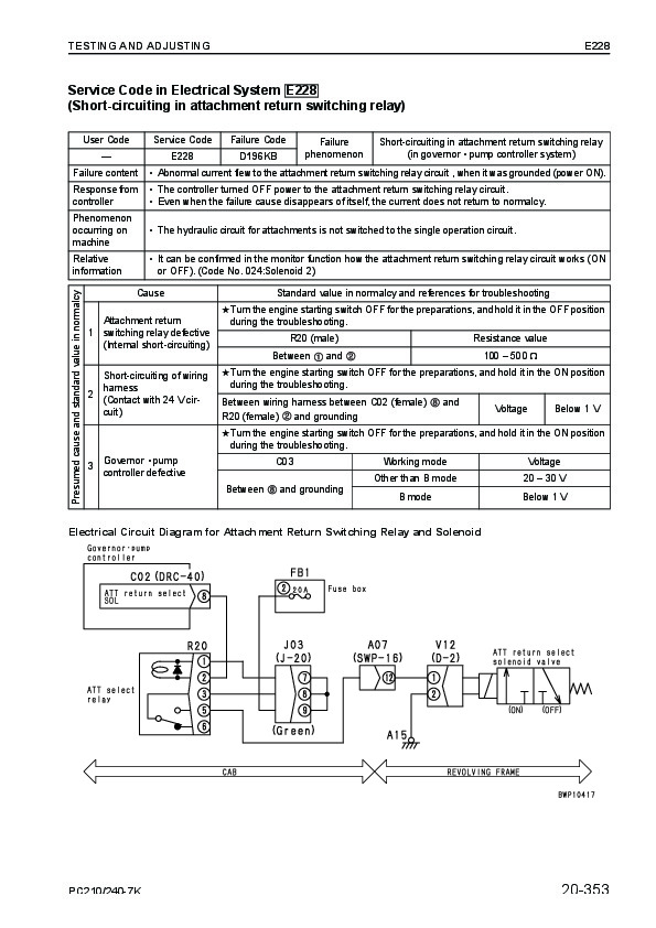
Failure code [989L00] Engine Controller Lock Caution 1…1592
Failure code [989M00] Engine Controller Lock Caution 2…1592
Failure code [989N00] Engine Controller Lock Caution 3…1593
Failure code [AA10NX] Air Cleaner Clogging…1593
Failure code [AB00KE] Charge Voltage Low…1594
Failure code [B@BAZG] Eng Oil Press. Low…1596
Failure code [B@BAZK] Eng Oil Level Low…1596
Failure code [B@BCNS] Eng Water Overheat…1597
Failure code [B@BCZK] Eng Water Level Low…1597
Failure code [B@HANS] Hydr Oil Overheat…1598
Failure code [CA111] EMC Critical Internal Failure…1598
Failure code [CA115] Eng Ne and Bkup Speed Sens Error…1599
Failure code [CA122] Chg Air Press Sensor High Error…1600
Failure code [CA123] Chg Air Press Sensor Low Error…1602
Failure code [CA131] Throttle Sensor High Error…1604
Failure code [CA132] Throttle Sensor Low Error…1606
Failure code [CA144] Coolant Temp Sens High Error…1608
Failure code [CA145] Coolant Temp Sens Low Error…1610
Failure code [CA153] Chg Air Temp Sensor High Error…1612
Failure code [CA154] Chg Air Temp Sensor Low Error…1614
Failure code [CA155] Chg Air Temp High Speed Derate…1616
Failure code [CA187] Sens Supply 2 Volt Low Error…1618
Failure code [CA221] Ambient Press Sens High Error…1620
Failure code [CA222] Ambient Press Sens Low Error…1622
Failure code [CA227] Sens Supply 2 Volt High Error…1624
Failure code [CA234] Eng Overspeed…1625
Failure code [CA238] Ne Speed Sens Supply Volt Error…1626
Failure code [CA271] IMV/PCV1 Short Error…1627
Failure code [CA272] IMV/PCV1 Open Error…1628
Failure code [CA322] Inj #1 (L#1) Open/Short Error…1630
Failure code [CA323] Inj #5 (L#5) Open/Short Error…1632
Failure code [CA324] Inj #3 (L#3) Open/Short Error…1634
Failure code [CA325] Inj #6 (L#6) Open/Short Error…1636
Failure code [CA331] Inj #2 (L#2) Open/Short Error…1638
Failure code [CA332] Inj #4 (L#4) Open/Short Error…1640
40 Troubleshooting…1643
Troubleshooting by failure code (Display of code), Part 2…1643
Troubleshooting by failure code (Display of code), Part 2…1645
Failure code [CA342] Calibration Code Incompatibility…1645
Failure code [CA351] Injectors Drive Circuit Error…1646
Failure code [CA352] Sens Supply 1 Volt Low Error…1648
Failure code [CA386] Sens Supply 1 Volt High Error…1650
Failure code [CA428] Water in Fuel Sensor High Error…1652
Failure code [CA429] Water in Fuel Sensor Low Error…1654
Failure code [CA435] Eng Oil Press Sw Error…1656
Failure code [CA441] Battery Voltage Low Error…1657
Failure code [CA442] Battery Voltage High Error…1660
Failure code [CA449] Rail Press Very High Error…1662
Failure code [CA451] Rail Press Sensor High Error…1664
Failure code [CA452] Rail Press Sensor Low Error…1666
Failure code [CA488] Chg Air Temp High Torque Derate…1668
Failure code [CA553] Rail Press High Error…1668
Failure code [CA559] Rail Press Low Error…1669
Failure code [CA689] Eng Ne Speed Sensor Error…1670
Failure code [CA731] Eng Bkup Speed Sens Phase Error…1672
Failure code [CA757] All Continuous Data Lost Error…1674
Failure code [CA778] Eng Bkup Speed Sensor Error…1676
Failure code [CA1633] KOMNET Datalink Timeout Error…1678
Failure code [CA2185] Throt Sens Sup Volt High Error…1680
Failure code [CA2186] Throt Sens Sup Volt Low Error…1681
Failure code [CA2249] Rail Press Very Low Error…1682
Failure code [CA2311] IMV Solenoid Error…1684
Failure code [CA2555] Grid Htr Relay Volt High Error…1686
Failure code [CA2556] Grid Htr Relay Volt Low Error…1688
Failure code [D19JKZ] Personal Code Relay Abnormality…1690
Failure code [D862KA] GPS Antenna Discon…1692
Failure code [DA25KP] 5V Sensor 1 Power Abnormality…1693
Failure code [DA29KQ] Model Selection Abnormality…1700
40 Troubleshooting…1705
Troubleshooting by failure code (Display of code), Part 3…1705
Troubleshooting by failure code (Display of code), Part 3…1708
Failure code [DA2RMC] CAN Discon (Pump Con Detected)…1708
Failure code [DAFGMC] GPS Module Error…1710
Failure code [DAFRMC] CAN Discon (Monitor Detected)…1712
Failure code [DGH2KB] Hydr Oil Sensor Short…1714
Failure code [DHPAMA] F Pump Press Sensor Abnormality…1716
Failure code [DHPBMA] R Pump Press Sensor Abnormality…1718
Failure code [DHS3MA] Arm Curl PPC Press Sensor Abnormality…1720
Failure code [DHS4MA] Bucket Curl PPC Press Sensor Abnormality…1722
Failure code [DHS8MA] Boom Raise PPC Press Sensor Abnormality…1724
Failure code [DHSAMA] Swing RH PPC Press Sensor Abnormality…1726
Failure code [DHSBMA] Swing LH PPC Press Sensor Abnormality…1728
Failure code [DHSDMA] Bucket Dump PPC Press Sensor Abnormality…1730
Failure code [DHX1MA] Overload Sensor Abnormality (Analog)…1732
Failure code [DW43KA] Travel Speed Sol Discon…1734
Failure code [DW43KB] Travel Speed Sol Short…1736
Failure code [DW45KA] Swing Brake Sol Discon…1738
Failure code [DW45KB] Swing Brake Sol Short…1740
Failure code [DW91KA] Travel Junction Sol Discon…1742
Failure code [DW91KB] Travel Junction Sol Short…1744
Failure code [DWA2KA] Service Sol Discon…1746
Failure code [DWA2KB] Service Sol Short…1747
Failure code [DWK0KA] 2-stage Relief Sol Discon…1748
Failure code [DWK0KB] 2-stage Relief Sol Short…1750
40 Troubleshooting…1753
Troubleshooting by failure code (Display of code), Part 4…1753
Troubleshooting by failure code (Display of code), Part 4…1756
Failure code [DXA8KA] PC-EPC (F) Sol Discon…1756
Failure code [DXA8KB] PC-EPC (F) Sol Short…1758
Failure code [DXA9KA] PC-EPC (R) Sol Discon…1760
Failure code [DXA9KB] PC-EPC (R) Sol Short…1762
Failure code [DXE0KA] LS-EPC Sol Discon…1764
Failure code [DXE0KB] LS-EPC Sol Short…1766
Failure code [DXE4KA] Service Current EPC Discon…1768
Failure code [DXE4KB] Service Current EPC Short…1770
Failure code [DXE5KA] Merge-divider Main Sol Discon…1772
Failure code [DXE5KB] Merge-divider Main Sol Short…1774
Failure code [DXE6KA] Merge-divider LS Sol Discon…1776
Failure code [DXE6KB] Merge-divider LS Sol Short…1778
Failure code [DY20KA] Wiper Working Abnormality…1780
Failure code [DY20MA] Wiper Parking Abnormality…1782
Failure code [DY2CKA] Washer Drive Discon…1784
Failure code [DY2CKB] Washer Drive Short…1786
Failure code [DY2DKB] Wiper Drive (For) Short…1788
Failure code [DY2EKB] Wiper Drive (Rev) Short…1790
40 Troubleshooting…1793
Troubleshooting of electrical system (E-mode)…1793
Troubleshooting of electrical system (E-mode)…1795
Before carrying out troubleshooting of electrical system…1795
Information in troubleshooting table…1797
E-1 When starting switch turned ON, machine monitor displays nothing…1798
E-2 When starting switch turned ON (before starting engine), basic check item lights up…1800
E-3 Engine does not start (Engine does not turn)…1803
E-4 Preheater does not operate…1806
E-5 Automatic warm-up system does not operate (in cold season)…1808
E-6 All work equipment, swing, and travel mechanism do not move or cannot be locked…1810
E-7 Precaution lights up while engine is running…1812
E-8 Emergency stop item lights up while engine is running…1817
E-9 Engine coolant temperature gauge does not indicate normally…1818
E-10 Hydraulic oil temperature gauge does not indicate normally…1819
E-11 Fuel level gauge does not indicate normally…1821
E-12 Contents of display by machine monitor are different from applicable machine…1823
E-13 Machine monitor does not display some items…1823
E-14 Function switch does not work…1823
E-15 Auto-decelerator does not operate normally…1824
E-16 Working mode does not change…1825
E-17 Travel speed does not change…1826
E-18 Alarm buzzer cannot be stopped…1827
E-19 Windshield wiper and window washer do not operate…1828
E-20 Power maximizing function does not operate normally…1830
E-21 Swing holding brake does not operate normally…1832
E-22 Travel alarm does not sound or does not stop sounding…1834
E-23 Air conditioner does not operate normally (including air conditioner abnormality record)…1836
E-24 When starting switch is turned OFF, service meter is not displayed…1848
E-25 Machine monitor cannot be set in service mode…1848
E-26 Monitoring function does not display lever control signal normally…1849
E-27 KOMTRAX system does not operate normally…1858
40 Troubleshooting…1861
Troubleshooting of hydraulic and mechanical system (H-mode)…1861
Troubleshooting of hydraulic and mechanical system (H-mode)…1864
System diagram of hydraulic and mechanical system…1864
Information in troubleshooting table…1866
H-1 Speed or power of whole work equipment, swing, and travel is low…1867
H-2 Engine speed lowers extremely or engine stalls…1869
H-3 Work equipment, swing, and travel systems do not work…1870
H-4 Abnormal sound comes out from around hydraulic pump…1870
H-5 Auto-decelerator does not operate…1871
H-6 Fine control performance or response is low…1871
H-7 Speed or power of boom is low…1872
H-8 Speed or power of arm is low…1873
H-9 Speed or power of bucket is low…1874
H-10 Work equipment does not move singly…1874
H-11 Hydraulic drift of work equipment is large…1875
H-12 Time lag of work equipment is large…1877
H-13 When part of work equipment is relieved singly, other parts of work equipment move…1877
H-14 Power maximizing function does not work…1878
H-15 In compound operation of work equipment, speed of part loaded more is low…1878
H-16 When machine swings and raises boom simultaneously, boom rising speed is low…1879
H-17 When machine swings and travels simultaneously, travel speed lowers largely…1879
H-18 Machine deviates during travel…1880
H-19 Travel speed is low…1881
H-20 Machine is not steered well or steering power is low…1882
H-21 Travel speed does not change or travel speed is low/high…1883
H-22 Travel system does not move (only one side)…1884
H-23 Upper structure does not swing…1885
H-24 Swing acceleration or swing speed is low…1887
H-25 Upper structure overruns remarkably when it stops swinging…1888
H-26 Large shock is made when upper structure stops swinging…1889
H-27 Large sound is made when upper structure stops swinging…1889
H-28 Hydraulic drift of swing is large…1890
H-29 Attachment circuit is not changed…1891
H-30 Oil flow in attachment circuit cannot be controlled…1891
40 Troubleshooting…1893
Troubleshooting of engine (S-mode)…1893
Troubleshooting of engine (S-mode)…1895
Method of using troubleshooting chart…1895
S-1 Starting performance is poor…1898
S-2 Engine does not start…1899
S-3 Engine does not pick up smoothly…1902
S-4 Engine stops during operations…1903
S-5 Engine does not rotate smoothly…1904
S-6 Engine lack output (or lacks power)…1905
S-7 Exhaust smoke is black (incomplete combustion)…1906
S-8 Oil consumption is excessive (or exhaust smoke is blue)…1907
S-9 Oil becomes contaminated quickly…1908
S-10 Fuel consumption is excessive…1909
S-11 Oil is in coolant (or coolant spurts back or coolant level goes down)…1910
S-12 Oil pressure drops…1911
S-13 Oil level rises (Entry of coolant/fuel)…1912
S-14 Coolant temperature becomes too high (overheating)…1913
S-15 Abnormal noise is made…1914
S-16 Vibration is excessive…1915
50 Disassembly and assembly…1917
Disassembly and assembly related information…1917
Disassembly and assembly related information…1918
How to read this manual…1918
List of adhesives…1920
Special tool list…1923
Sketches of special tools…1928
50 Disassembly and assembly…1933
Engine cooling related…1933
Engine cooling related…1934
Removal and installation of fuel supply pump assembly…1934
Removal and installation of fuel injector assembly…1936
Removal and installation of engine front seal…1943
Removal and installation of engine rear seal…1946
Removal and installation of cylinder head assembly…1949
Removal and installation of radiator assembly…1961
Removal and installation of assembly hydraulic oil cooler assembly…1964
Removal and installation of aftercooler assembly…1966
Removal and installation of fuel cooler assembly…1968
Removal and installation of engine and hydraulic pump assemblies…1969
50 Disassembly and assembly…1981
Power train…1981
Power train…1982
Removal and installation of final drive assembly…1982
Disassembly and assembly of final drive assembly…1984
Removal and installation of swing motor and swing machinery assembly…2000
Disassembly and assembly of swing motor and swing machinery assembly…2002
Removal and installation of swing circle assembly…2012
50 Disassembly and assembly…2015
Under carriage and frame…2015
Under carriage and frame…2016
Disassembly and assembly of carrier roller…2016
Disassembly and assembly of track roller assembly…2019
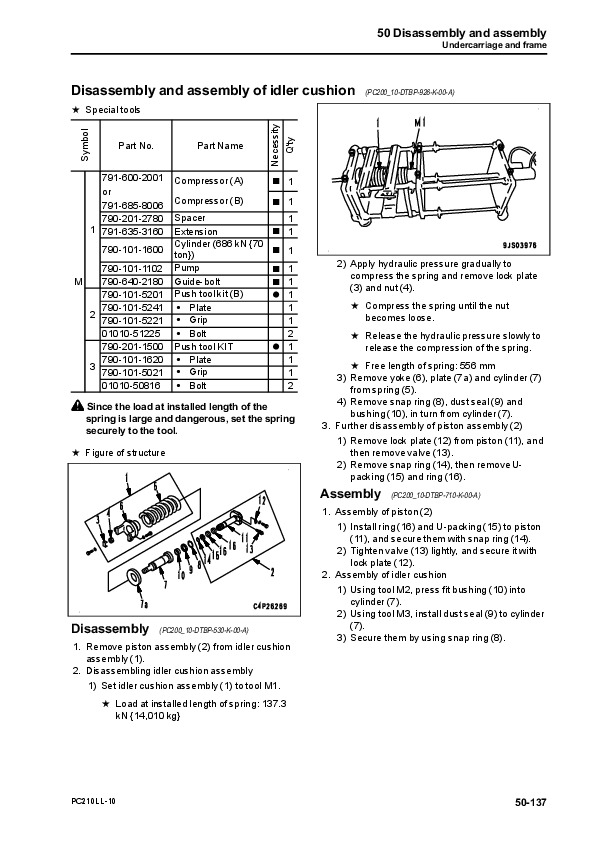
Disassembly and assembly of idler assembly…2021
Disassembly and assembly of recoil spring…2024
Removal and installation of sprocket…2026
Expansion and installation of track shoe assembly…2027
Removal and installation of revolving frame assembly…2029
Removal and installation of counterweight assembly…2031
50 Disassembly and assembly…2033
Hydraulic system…2033
Hydraulic system…2034
Removal and installation of center swivel joint assembly…2034
Disassembly and assembly of center swivel joint assembly…2036
Removal and installation of hydraulic tank assembly…2037
Removal and installation of control valve assembly…2040
Disassembly and assembly of control valve assembly…2045
Removal and installation of hydraulic pump assembly…2049
Removal and installation of oil seal in hydraulic pump input shaft…2054
Disassembly and assembly of work equipment PPC valve assembly…2055
Disassembly and assembly of travel PPC valve assembly…2056
Disassembly and assembly of hydraulic cylinder assembly…2057
50 Disassembly and assembly…2065
Work equipment…2065
Work equipment…2066
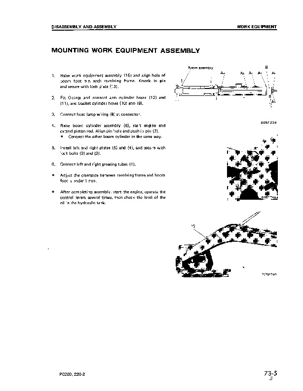
Removal and installation of the work equipment assembly…2066
50 Disassembly and assembly…2071
Cab related…2071
Cab related…2072
Removal and installation of operator's cab assembly…2072
Removal and installation of operator cab glass (stuck glass)…2075
Removal and installation of front window assembly…2085
Removal and installation of floor frame assembly…2092
50 Disassembly and assembly…2097
Electric components…2097
Electric components…2098
Removal and installation of air conditioner unit assembly…2098
Removal and installation of KOMTRAX communication modem assembly…2101
Removal and installation of monitor assembly…2102
Removal and installation of pump controller assembly…2104
Removal and installation of engine controller assembly…2105
90 Diagrams and drawings…2107
Hydraulic diagrams and drawings…2107
Hydraulic diagrams and drawings…2109
Hydraulic circuit diagram…2109
90 Diagrams and drawings…2113
Electrical diagrams and drawings…2113
Electrical diagrams and drawings…2115
Electrical circuit diagram (1/5)…2115
Electrical circuit diagram (2/5)…2117
Electrical circuit diagram (3/5)…2119
Electrical circuit diagram (4/5)…2121
Electrical circuit diagram (5/5)…2123
UEN00084-07 – Hydraulic Excavator PC210-8, PC210LC-8, PC210NLC-8, PC230NHD-8, PC240LC-8, PC240NLC-8 Shop Manual…2127
00 Index and foreword…2129
Index…2129
Organization list of the shop manual…2130
Table of contents…2132
00 Index and foreword…2143
Foreword and general information…2143
Foreword and general information…2144
Safety notice…2144
How to read the shop manual…2148
Explanation of terms for maintenance standard…2150
Handling electric equipment and hydraulic component…2152
How to read electric wire code…2160
Method of disassembling and connecting push-pull type coupler…2163
Standard tightening torque table…2166
Conversion table…2170
01 Specification…2177
Specification and technical data…2177
Specification and technical data…2178
Specification dimension drawings…2178
Working range diagram…2179
Specifications…2180
Weight table…2184
Table of fuel, coolant and lubricants…2188
10 Structure, function and maintenance standard…2191
Engine and cooling system…2191
Engine and cooling system…2192
Engine related parts…2192
Radiator, oil cooler, aftercooler and fuel cooler…2193
Diesel Particulate Filter…2194
Diesel Particulate Filter – Component Parts…2195
System Description…2196
Regeneration…2196
10 Structure, function and maintenance standard…2199
Power train…2199
Power train…2200
Power train…2200
Final drive…2202
Swing machinery…2204
Swing circle…2208
10 Structure, function and maintenance standard…2211
Undercarriage and frame…2211
Undercarriage and frame…2212
Track frame and recoil spring…2212
Idler…2214
Carrier roller…2216
Track roller…2217
Track shoe…2218
10 Structure, function and maintenance standard…2225
Hydraulic system, Part 1…2225
Hydraulic system, Part 1…2226
Hydraulic equipment layout drawing…2226
Hydraulic tank and filter…2228
Hydraulic pump…2229
Hydraulic pump…2230
Pilot oil filter…2253
10 Structure, function and maintenance standard…2255
Hydraulic system, Part 2…2255
Hydraulic system, Part 2…2256
Control valve…2256
CLSS…2269
Functions and operation by valve…2274
Hydraulic drift prevention valve…2300
10 Structure, function and maintenance standard…2313
Hydraulic system, Part 3…2313
Hydraulic system, Part 3…2315
Swing motor…2315
Centre swivel joint…2324
Travel motor…2327
PPC valve…2338
Valve control…2358
ATT EPC Valve Assembly…2360
Solenoid valve…2362
PPC Accumulator…2364
Return oil filter…2365
Attachment circuit selector valve…2366
Quick coupler control valve – For PC210 K50001 ~ K51094, PC230 K50001 ~ K50113 and PC240 K50001~K50303…2368
Quick coupler control valve – For PC210 K51095 – K53243, PC230 K50114 – K50286 and PC240 K50304 – K51093.)…2370
Quick coupler control valve – For PC210 K53424 and up, PC230 K50287 and up and PC240 K51094 and up…2372
Hydraulic cylinder…2374
10 Structure, function and maintenance standard…2379
Work equipment…2379
Work equipment…2380
Dimensions of components…2380
10 Structure, function and maintenance standard…2387
Cab and its attachments…2387
Cab and its attachments…2388
Air conditioner piping…2388
10 Structure, function and maintenance standard…2391
Electrical system…2391
Electrical system…2392
Engine control…2392
Electrical control system…2400
Monitor system…2426
Sensor…2457
PPC Levers…2460
KOMTRAX terminal system…2462
10 Structure, function and maintenance standard…2465
Auto Grease system…2465
Outline of Auto Grease System…2466
20 Standard value table…2481
Standard service value table…2481
Standard service value table…2482
Standard value table for engine related parts…2482
Standard value table for chassis related parts…2484
30 Testing and adjusting…2503
Testing and adjusting, Part 1…2503
Testing and adjusting, Part 1…2505
Tools for testing, adjusting, and troubleshooting…2505
Measuring engine speed…2508
Measuring intake air pressure (boost pressure)…2509
Checking exhaust gas colour…2510
Adjusting valve clearance…2511
Measuring compression pressure…2513
Measuring blow-by pressure…2515
Measuring engine oil pressure…2516
Handling fuel system parts…2517
Releasing residual pressure from fuel system…2517
Measuring fuel pressure…2518
Measuring fuel return rate and leakage…2520
Bleeding air from fuel circuit…2522
Checking fuel circuit for leakage…2524
Checking and adjusting air conditioner compressor belt tension…2525
Measuring swing circle bearing clearance…2526
Checking and adjusting track shoe tension…2527
Measuring and adjusting oil pressure in work equipment, swing, and travel circuits…2529
Measuring control circuit basic pressure…2533
Measuring and adjusting oil pressure in pump PC control circuit…2534
Measuring and adjusting oil pressure in pump LS control circuit…2538
Measuring solenoid valve output pressure…2544
Measuring PPC valve output pressure…2547
Adjusting play of work equipment and swing PPC valves…2549
Measuring and adjusting quick coupler control valve output pressure – For PC210 K50001 – K53423, PC230 K50001 – K50286 and PC240 K50001 – K51093…2550
Measuring and adjusting quick coupler control valve output pressure – For PC210 K53424 and up, PC230 K50287 and up and PC240 K51094 and up…2551
Checking parts which cause hydraulic drift of work equipment…2552
Releasing residual pressure from hydraulic circuit…2554
Measuring oil leakage…2555
Bleeding air from each part…2558
Checking cab tipping stopper…2561
Adjusting mirrors…2562
Adjusting mirrors…2564
30 Testing and adjusting…2567
Testing and adjusting, Part 2…2567
Testing and adjusting, Part 2…2568
Special functions of machine monitor…2568
30 Testing and adjusting…2633
Testing and adjusting, Part 3…2633
Testing and adjusting, Part 3…2634
Handling high-voltage circuit of engine controller…2634
Preparation work for troubleshooting of electrical system…2635
Procedure for testing diodes…2639
Pm Clinic service…2641
Warning…2643
Pm Clinic service…2647
40 Troubleshooting…2655
General information on troubleshooting…2655
General information on troubleshooting…2656
Points to remember when troubleshooting…2656
Sequence of events in troubleshooting…2657
Check before troubleshooting…2658
Classification and procedures for troubleshooting…2659
How to read electric wire code…2663
Connection table for connector pin numbers…2666
T-boxes and T-adapters table…2697
40 Troubleshooting…2703
Troubleshooting by failure code (Display of code), Part 1…2703
Troubleshooting by failure code (Display of code), Part 1…2705
Failure codes table…2705
Before carrying out troubleshooting when failure code is displayed…2710
Before carrying out troubleshooting when failure code is displayed…2711
Information in troubleshooting table…2716
Failure code [989L00] Engine Controller Lock Caution 1…2718
Failure code [989M00] Engine Controller Lock Caution 2…2718
Failure code [989N00] Engine Controller Lock Caution 3…2719
Failure code [AA10NX] Air Cleaner Clogging…2719
Failure code [AB00KE] Charge Voltage Low…2720
Failure code [B@BAZG] Eng Oil Press. Low…2722
Failure code [B@BAZK] Eng Oil Level Low…2722
Failure code [B@BCNS] Eng Water Overheat…2723
Failure code [B@BCZK] Eng Water Level Low…2723
Failure code [B@HANS] Hydr Oil Overheat…2724
Failure code [CA111] EMC Critical Internal Failure…2724
Failure code [CA115] Eng Ne and Bkup Speed Sens Error…2725
Failure code [CA122] Chg Air Press Sensor High Error…2726
Failure code [CA123] Chg Air Press Sensor Low Error…2728
Failure code [CA131] Throttle Sensor High Error…2730
Failure code [CA132] Throttle Sensor Low Error…2732
Failure code [CA144] Coolant Temp Sens High Error…2734
Failure code [CA145] Coolant Temp Sens Low Error…2736
Failure code [CA153] Chg Air Temp Sensor High Error…2738
Failure code [CA154] Chg Air Temp Sensor Low Error…2740
Failure code [CA155] Chg Air Temp High Speed Derate…2742
Failure code [CA187] Sens Supply 2 Volt Low Error…2744
Failure code [CA221] Ambient Press Sens High Error…2746
Failure code [CA222] Ambient Press Sens Low Error…2748
Failure code [CA227] Sens Supply 2 Volt High Error…2750
Failure code [CA234] Eng Overspeed…2751
Failure code [CA238] Ne Speed Sens Supply Volt Error…2752
Failure code [CA271] IMV/PCV1 Short Error…2753
Failure code [CA272] IMV/PCV1 Open Error…2754
Failure code [CA322] Inj #1 (L#1) Open/Short Error…2756
Failure code [CA323] Inj #5 (L#5) Open/Short Error…2758
Failure code [CA324] Inj #3 (L#3) Open/Short Error…2760
Failure code [CA325] Inj #6 (L#6) Open/Short Error…2762
Failure code [CA331] Inj #2 (L#2) Open/Short Error…2764
Failure code [CA332] Inj #4 (L#4) Open/Short Error…2766
40 Troubleshooting…2769
Troubleshooting by failure code (Display of code), Part 2…2769
Troubleshooting by failure code (Display of code), Part 2…2771
Failure code [CA342] Calibration Code Incompatibility…2771
Failure code [CA351] Injectors Drive Circuit Error…2772
Failure code [CA352] Sens Supply 1 Volt Low Error…2774
Failure code [CA386] Sens Supply 1 Volt High Error…2776
Failure code [CA428] Water in Fuel Sensor High Error…2778
Failure code [CA429] Water in Fuel Sensor Low Error…2780
Failure code [CA435] Eng Oil Press Sw Error…2782
Failure code [CA441] Battery Voltage Low Error…2783
Failure code [CA442] Battery Voltage High Error…2786
Failure code [CA449] Rail Press Very High Error…2788
Failure code [CA451] Rail Press Sensor High Error…2790
Failure code [CA452] Rail Press Sensor Low Error…2792
Failure code [CA488] Chg Air Temp High Torque Derate…2794
Failure code [CA553] Rail Press High Error…2794
Failure code [CA559] Rail Press Low Error…2795
Failure code [CA689] Eng Ne Speed Sensor Error…2796
Failure code [CA731] Eng Bkup Speed Sens Phase Error…2798
Failure code [CA757] All Continuous Data Lost Error…2800
Failure code [CA778] Eng Bkup Speed Sensor Error…2802
Failure code [CA1633] KOMNET Datalink Timeout Error…2804
Failure code [CA2185] Throt Sens Sup Volt High Error…2806
Failure code [CA2186] Throt Sens Sup Volt Low Error…2807
Failure code [CA2249] Rail Press Very Low Error…2808
Failure code [CA2311] IMV Solenoid Error…2810
Failure code [CA2555] Grid Htr Relay Volt High Error…2812
Failure code [CA2556] Grid Htr Relay Volt Low Error…2814
Failure code [D19JKZ] Personal Code Relay Abnormality…2816
Failure code [D862KA] GPS Antenna Discon…2818
Failure code [DA25KP] 5V Sensor 1 Power Abnormality…2819
Failure code [DA29KQ] Model Selection Abnormality…2826
40 Troubleshooting…2831
Troubleshooting by failure code (Display of code), Part 3…2831
Troubleshooting by failure code (Display of code), Part 3…2834
Failure code [DA2RMC] CAN Discon (Pump Con Detected)…2834
Failure code [DAFGMC] GPS Module Error…2836
Failure code [DAFRMC] CAN Discon (Monitor Detected)…2838
Failure code [DGH2KB] Hydr Oil Sensor Short…2840
Failure code [DHPAMA] F Pump Press Sensor Abnormality…2842
Failure code [DHPBMA] R Pump Press Sensor Abnormality…2844
Failure code [DHS3MA] Arm Curl PPC Press Sensor Abnormality…2846
Failure code [DHS4MA] Bucket Curl PPC Press Sensor Abnormality…2848
Failure code [DHS8MA] Boom Raise PPC Press Sensor Abnormality…2850
Failure code [DHSAMA] Swing RH PPC Press Sensor Abnormality…2852
Failure code [DHSBMA] Swing LH PPC Press Sensor Abnormality…2854
Failure code [DHSDMA] Bucket Dump PPC Press Sensor Abnormality…2856
Failure code [DHX1MA] Overload Sensor Abnormality (Analog)…2858
Failure code [DW43KA] Travel Speed Sol Discon…2860
Failure code [DW43KB] Travel Speed Sol Short…2862
Failure code [DW45KA] Swing Brake Sol Discon…2864
Failure code [DW45KB] Swing Brake Sol Short…2866
Failure code [DW91KA] Travel Junction Sol Discon…2868
Failure code [DW91KB] Travel Junction Sol Short…2870
Failure code [DWA2KA] Service Sol Discon…2872
Failure code [DWA2KB] Service Sol Short…2873
Failure code [DWK0KA] 2-stage Relief Sol Discon…2874
Failure code [DWK0KB] 2-stage Relief Sol Short…2876
40 Troubleshooting…2879
Troubleshooting by failure code (Display of code), Part 4…2879
Troubleshooting by failure code (Display of code), Part 4…2881
Failure code [DXA8KA] PC-EPC (F) Sol Discon…2881
Failure code [DXA8KB] PC-EPC (F) Sol Short…2883
Failure code [DXA9KA] PC-EPC (R) Sol Discon…2885
Failure code [DXA9KB] PC-EPC (R) Sol Short…2887
Failure code [DXE0KA] LS-EPC Sol Discon…2889
Failure code [DXE0KB] LS-EPC Sol Short…2891
Failure code [DXE4KA] Service Current EPC Discon…2893
Failure code [DXE4KB] Service Current EPC Short…2895
Failure code [DXE5KA] Merge-divider Main Sol Discon…2897
Failure code [DXE5KB] Merge-divider Main Sol Short…2899
Failure code [DXE6KA] Merge-divider LS Sol Discon…2901
Failure code [DXE6KB] Merge-divider LS Sol Short…2903
Failure code [DY20KA] Wiper Working Abnormality…2905
Failure code [DY20MA] Wiper Parking Abnormality…2907
Failure code [DY2CKA] Washer Drive Discon…2909
Failure code [DY2CKB] Washer Drive Short…2911
Failure code [DY2DKB] Wiper Drive (For) Short…2913
Failure code [DY2EKB] Wiper Drive (Rev) Short…2915
Failure code [DXEAKA] Service Current EPC1 Discon…2917
Failure code [DXEAKB] Service Current EPC1 Short…2918
Failure code [DXE7KA] Service Current EPC2 Discon…2919
Failure code [DXE7KB] Service Current EPC2 Short…2920
Failure code [DXE8KA] Service Current EPC3 Discon…2921
Failure code [DXE8KB] Service Current EPC3 Short…2922
Failure code [DXE9KA] Service Current EPC4 Discon…2923
Failure code [DXE9KB] Service Current EPC4 Short…2924
Failure code [DFB1KZ] Service Lever Potentio 1 Abnormality…2927
Failure code [DFB2KZ] Service Lever Potentio 2 Abnormality…2929
Failure code [DFB5KZ] Service Lever Sub Potentio 1 Abnormality…2931
Failure code [DFB6KZ] Service Lever Sub Potentio 2 Abnormality…2933
Failure code [DFB3L8] Service Lever 1 Potentio Error…2935
Failure code [DFB4L8] Service Lever 2 Potentio Error…2936
40 Troubleshooting…2939
Troubleshooting of electrical system (E-mode)…2939
Troubleshooting of electrical system (E-mode)…2941
Before carrying out troubleshooting of electrical system…2941
Troubleshooting of electrical system (E-mode)…2942
Information in troubleshooting table…2945
E-1 When starting switch turned ON, machine monitor displays nothing…2946
E-2 When starting switch turned ON (before starting engine), basic check item lights up…2948
E-3 Engine does not start (Engine does not turn)…2951
E-4 Preheater does not operate…2954
E-5 Automatic warm-up system does not operate (in cold season)…2956
E-6 All work equipment, swing, and travel mechanism do not move or cannot be locked…2958
E-7 Precaution lights up while engine is running…2960
E-8 Emergency stop item lights up while engine is running…2965
E-9 Engine coolant temperature gauge does not indicate normally…2966
E-10 Hydraulic oil temperature gauge does not indicate normally…2967
E-11 Fuel level gauge does not indicate normally…2969
E-12 Contents of display by machine monitor are different from applicable machine…2971
E-13 Machine monitor does not display some items…2971
E-14 Function switch does not work…2971
E-15 Auto-decelerator does not operate normally…2972
E-16 Working mode does not change…2973
E-17 Travel speed does not change…2974
E-18 Alarm buzzer cannot be stopped…2975
E-18 Alarm buzzer cannot be stopped…2976
E-19 Windshield wiper and window washer do not operate…2978
E-20 Power maximising function does not operate normally…2980
E-20 Power maximising function does not operate normally…2982
E-21 Swing holding brake does not operate normally…2984
E-22 Travel alarm does not sound or does not stop sounding…2986
E-23 Air conditioner does not operate normally (including air conditioner abnormality record)…2988
E-24 When starting switch is turned OFF, service meter is not displayed…3000
E-25 Machine monitor cannot be set in service mode…3000
E-26 Monitoring function does not display lever control signal normally…3001
E-27 KOMTRAX system does not operate normally…3010
40 Troubleshooting…3013
Troubleshooting of hydraulic and mechanical system (H-mode)…3013
Troubleshooting of hydraulic and mechanical system (H-mode)…3016
System diagram of hydraulic and mechanical system…3016
Information in troubleshooting table…3018
H-1 Speed or power of whole work equipment, swing, and travel is low…3019
H-2 Engine speed lowers extremely or engine stalls…3021
H-3 Work equipment, swing, and travel systems do not work…3022
H-4 Abnormal sound comes out from around hydraulic pump…3022
H-5 Auto-decelerator does not operate…3023
H-6 Fine control performance or response is low…3023
H-7 Speed or power of boom is low…3024
H-8 Speed or power of arm is low…3025
H-9 Speed or power of bucket is low…3026
H-10 Work equipment does not move singly…3026
H-11 Hydraulic drift of work equipment is large…3027
H-12 Time lag of work equipment is large…3029
H-13 When part of work equipment is relieved singly, other parts of work equipment move…3029
H-14 Power maximizing function does not work…3030
H-15 In compound operation of work equipment, speed of part loaded more is low…3030
H-16 When machine swings and raises boom simultaneously, boom rising speed is low…3031
H-17 When machine swings and travels simultaneously, travel speed lowers largely…3031
H-18 Machine deviates during travel…3032
H-19 Travel speed is low…3033
H-20 Machine is not steered well or steering power is low…3034
H-21 Travel speed does not change or travel speed is low/high…3035
H-22 Travel system does not move (only one side)…3036
H-23 Upper structure does not swing…3037
H-24 Swing acceleration or swing speed is low…3039
H-25 Upper structure overruns remarkably when it stops swinging…3040
H-26 Large shock is made when upper structure stops swinging…3041
H-27 Large sound is made when upper structure stops swinging…3041
H-28 Hydraulic drift of swing is large…3042
H-29 Attachment circuit is not changed…3043
H-30 Oil flow in attachment circuit cannot be controlled…3043
Quick coupler…3044
Quick coupler…3046
Quick coupler…3048
40 Troubleshooting…3053
Troubleshooting of engine (S-mode)…3053
Troubleshooting of engine (S-mode)…3055
Method of using troubleshooting chart…3055
S-1 Starting performance is poor…3058
S-2 Engine does not start…3059
S-3 Engine does not pick up smoothly…3062
S-4 Engine stops during operations…3063
S-5 Engine does not rotate smoothly…3064
S-6 Engine lack output (or lacks power)…3065
S-7 Exhaust smoke is black (incomplete combustion)…3067
S-8 Oil consumption is excessive (or exhaust smoke is blue)…3068
S-9 Oil becomes contaminated quickly…3069
S-10 Fuel consumption is excessive…3070
S-11 Oil is in coolant (or coolant spurts back or coolant level goes down)…3071
S-12 Oil pressure drops…3072
S-13 Oil level rises (Entry of coolant/fuel)…3073
S-14 Coolant temperature becomes too high (overheating)…3074
S-15 Abnormal noise is made…3075
S-16 Vibration is excessive…3076
S-17 Diesel Particulate Filter System…3077
40 Troubleshooting…3079
Troubleshooting of Auto Grease system…3079
50 Disassembly and assembly…3087
Disassembly and assembly related information…3087
Disassembly and assembly related information…3088
How to read this manual…3088
List of adhesives…3090
Special tool list…3093
Sketches of special tools…3098
50 Disassembly and assembly…3103
Engine cooling related…3103
Engine cooling related…3104
Removal and installation of fuel supply pump assembly…3104
Removal and installation of fuel injector assembly…3106
Removal and installation of engine front seal…3113
Removal and installation of engine rear seal…3116
Removal and installation of cylinder head assembly…3119
Removal and installation of radiator assembly…3131
Removal and installation of assembly hydraulic oil cooler assembly…3134
Removal and installation of aftercooler assembly…3136
Removal and installation of fuel cooler assembly…3138
Removal and installation of engine and hydraulic pump assemblies…3139
50 Disassembly and assembly…3151
Power train…3151
Power train…3152
Removal and installation of final drive assembly…3152
Disassembly and assembly of final drive assembly…3154
Removal and installation of swing motor and swing machinery assembly…3170
Disassembly and assembly of swing motor and swing machinery assembly…3172
Removal and installation of swing circle assembly…3182
50 Disassembly and assembly…3185
Under carriage and frame…3185
Under carriage and frame…3186
Disassembly and assembly of carrier roller…3186
Disassembly and assembly of track roller assembly…3189
Disassembly and assembly of idler assembly…3191
Disassembly and assembly of recoil spring…3194
Removal and installation of sprocket…3196
Expansion and installation of track shoe assembly…3197
Removal and installation of revolving frame assembly…3199
Removal and installation of counterweight assembly…3201
50 Disassembly and assembly…3203
Hydraulic system…3203
Hydraulic system…3204
Removal and installation of center swivel joint assembly…3204
Disassembly and assembly of center swivel joint assembly…3206
Removal and installation of hydraulic tank assembly…3207
Removal and installation of control valve assembly…3210
Disassembly and assembly of control valve assembly…3215
Removal and installation of hydraulic pump assembly…3219
Removal and installation of oil seal in hydraulic pump input shaft…3224
Disassembly and assembly of work equipment PPC valve assembly…3225
Disassembly and assembly of travel PPC valve assembly…3226
Disassembly and assembly of hydraulic cylinder assembly…3227
Disassembly and Assembly of Quick Coupler Valve – For PC210 K50001 – K53423, PC230 K50001 – K50286 and PC240 K50001 – K51093…3233
Disassembly and Assembly of Quick Coupler Valve – For PC210 K53424 and up, PC230 K50287 and up and PC240 K51094 and up…3234
50 Disassembly and assembly…3237
Work equipment…3237
Work equipment…3238
Removal and installation of the work equipment assembly…3238
50 Disassembly and assembly…3243
Cab related…3243
Cab related…3244
Removal and installation of operator's cab assembly…3244
Removal and installation of operator cab glass (stuck glass)…3247
Removal and installation of front window assembly…3257
Removal and installation of floor frame assembly…3264
50 Disassembly and assembly…3269
Electric components…3269
Electric components…3270
Removal and installation of air conditioner unit assembly…3270
Removal and installation of KOMTRAX communication modem assembly…3273
Removal and installation of monitor assembly…3274
Removal and installation of pump controller assembly…3276
Removal and installation of engine controller assembly…3277
90 Diagrams and drawings…3281
Hydraulic diagrams and drawings…3281
Hydraulic diagrams and drawings (for PC210 K50001~K51094, PC230 K50001~K50113 and PC240 K50001~K50303)…3283
Hydraulic circuit diagram 1/2…3283
Hydraulic circuit diagram 2/2…3285
Hydraulic diagrams and drawings (For PC210 K51095 and up, PC230 K50114 and up and PC240 K50304 and up)…3287
Hydraulic circuit diagram 1/2…3287
Hydraulic circuit diagram 2/2…3289
90 Diagrams and drawings…3293
Electrical diagrams and drawings…3293
Electrical diagrams and drawings (for PC210 K50001~K51094, PC230 K50001~K50113 and PC240 K50001~K50303)…3295
Electrical circuit diagram (1/5)…3295
Electrical circuit diagram (2/5)…3297
Electrical circuit diagram (3/5)…3299
Electrical circuit diagram (4/5)…3301
Electrical circuit diagram (5/5)…3303
Electrical diagrams and drawings (For PC210 K51095 ~ K52292, PC230 K50114 ~ K50200 and PC240 K50304 ~ K50595)…3305
Electrical circuit diagram (1/5)…3305
Electrical circuit diagram (2/5)…3307
Electrical circuit diagram (3/5)…3309
Electrical circuit diagram (4/5)…3311
Electrical circuit diagram (5/5)…3313
Electrical diagrams and drawings (for PC210 K52293 and up, PC230 K50201 and up and PC240 K50596 and up)…3315
Electrical circuit diagram (1/5)…3315
Electrical circuit diagram (2/5)…3317
Electrical circuit diagram (3/5)…3319
Electrical circuit diagram (4/5)…3321
Electrical circuit diagram (5/5)…3323
Connector arrangement diagram…3325
Electrical circuit diagram for air conditioner…3327
Komatsu Hydraulic Excavator PC210, PC210LC, PC210NLC, PC230NHD, PC240LC, PC240NLC Repair Service Manuals