Posted on

Komatsu Hydraulic Excavator PC200, PC200LC, PC210, PC210LC, PC220, PC220LC, PC230, PC230LC Repair Service Manuals


INSTANT DOWNLOAD


Complete service repair manual with Electrical Wiring Diagrams for Komatsu Hydraulic Excavator PC200-6, PC200LC-6, PC210-6, PC210LC-6, PC220-6, PC220LC-6, PC230-6, PC230LC-6, with all the technical information to maintain, diagnose, repair, rebuild like professional mechanics.

Komatsu Hydraulic Excavator PC200-6, PC200LC-6, PC210-6, PC210LC-6, PC220-6, PC220LC-6, PC230-6, PC230LC-6 workshop service repair manual includes:
* Numbered table of contents easy to use so that you can find the information you need fast.
* Detailed sub-steps expand on repair procedure information
* Numbered instructions guide you through every repair procedure step by step.
* Troubleshooting and electrical service procedures are combined with detailed wiring diagrams for ease of use.
* Notes, cautions and warnings throughout each chapter pinpoint critical information.
* Bold figure number help you quickly match illustrations with instructions.
* Detailed illustrations, drawings and photos guide you through every procedure.
* Enlarged inset helps you identify and examine parts in detail.

SEBM010106 – Hydraulic Excavator PC200-6, PC200LC-6, PC210-6, PC210LC-6, PC220-6, PC220LC-6, PC230-6, PC230LC-6 Shop Manual.pdf
SEAM002403 – Hydraulic Excavator PC200-6, PC200LC-6, PC210-6 Mighty, PC210LC-6 Mighty, PC220-6, PC220LC-6, PC230-6 Mighty, PC230LC-6 Mighty Operation & Maintenance Manual.pdf
SEAM002405 – Hydraulic Excavator PC200-6, PC200LC-6, PC210-6 Mighty, PC210LC-6 Mighty, PC220-6, PC220LC-6, PC230-6 Mighty, PC230LC-6 Mighty Operation & Maintenance Manual.pdf
SEAM002406 – Hydraulic Excavator PC200-6, PC200LC-6, PC210-6 Mighty, PC210LC-6 Mighty, PC220-6, PC220LC-6, PC230-6 Mighty, PC230LC-6 Mighty Operation & Maintenance Manual.pdf
SEAM002407 – Hydraulic Excavator PC200-6, PC200LC-6, PC210-6 Mighty, PC210LC-6 Mighty, PC220-6, PC220LC-6, PC230-6 Mighty, PC230LC-6 Mighty Operation & Maintenance Manual.pdf
SEAM002410T – Hydraulic Excavator PC200-6, PC200LC-6, PC210-6 Mighty, PC210LC-6 Mighty, PC220-6, PC220LC-6, PC230-6 Mighty, PC230LC-6 Mighty Operation & Maintenance Manual.pdf

PRODUCT DETAILS:
Total Pages: 2,665 pages
File Format: PDF
Language: English

SEAM002403 – Hydraulic Excavator PC200-6, PC200LC-6, PC210-6 Mighty, PC210LC-6 Mighty, PC220-6, PC220LC-6, PC230-6 Mighty, PC230LC-6 Mighty Operation & Maintenance Manual….2
1. FOREWORD….4
2. SAFETY INFORMATION….5
3. INTRODUCTION….6
4. LOCATION OF PLATES, TABLE TO ENTER SERIAL NO. AND DISTRIBUTOR….7
5. CONTENTS….8
SAFETY….12
6. GENERAL PRECAUTIONS….13
7. PRECAUTIONS DURING OPERATION….19
7.1 BEFORE STARTING ENGINE….19
7.2 OPERATING MACHINE….21
7.3 TRANSPORTATION….26
7.4 BATTERY….27
7.5 TOWING….28
7.6 BUCKET WITH HOOK….29
8. PRECAUTIONS FOR MAINTENANCE….32
8.1 BEFORE CARRYING OUT MAINTENANCE….32
8.2 DURING MAINTENANCE….35
9. POSITION FOR ATTACHING SAFETY LABELS….39
OPERATION….43
10. GENERAL VIEW….44
10.1 GENERAL VIEW OF MACHINE….44
10.2 GENERAL VIEW OF CONTROLS AND GAUGES….45
11. EXPLANATION OF COMPONENTS….46
11.1 MACHINE MONITOR….46
11.2 METER….57
11.3 SWITCHES….58
11.4 CONTROL LEVERS, PEDALS….62
11.5 CEILING WINDOW….67
11.6 FRONT WINDOW….68
11.7 DOOR LOCK….70
11.8 CAP, COVER WITH LOCK….71
11.9 HOT/COOL BOX….72
11.10 LUGGAGE BOX….72
11.11 ASHTRAY….72
11.12 AIR CONDITIONER….73
11.13 CAR RADIO….76
11.14 FUSE….80
11.15 FUSIBLE LINK….81
11.16 CONTROLLERS….81
11.17 TOOL BOX….81
11.18 GREASE PUMP HOLDER….81
11.19 HANDLING ACCUMULATOR….82
12. OPERATION….84
12.1 CHECK BEFORE STARTING ENGINE….84
12.2 STARTING ENGINE….94
12.3 OPERATIONS AND CHECKS AFTER STARTING ENGINE….97
12.4 MOVING MACHINE OFF….103
12.5 STEERING MACHINE….106
12.6 STOPPING MACHINE….108
12.7 SWINGING….109
12.8 OPERATION OF WORK EQUIPMENT….110
12.9 WORKING MODE SELECTION….111
12.10 PROHIBITIONS FOR OPERATION….113
12.11 PRECAUTIONS FOR OPERATION….115
12.12 PRECAUTIONS WHEN TRAVELING UP OR DOWN HILLS….116
12.13 HOW TO ESCAPE FROM MUD….118
12.14 WORK POSSIBLE USING HYDRAULIC EXCAVATOR….119
12.15 REPLACEMENT AND INVERSION OF BUCKET….120
12.16 PARKING MACHINE….122
12.17 CHECK AFTER FINISHING WORK….123
12.18 STOPPING ENGINE….124
12.19 CHECK AFTER STOPPING ENGINE….125
12.20 LOCKING….125
13. TRANSPORTATION….126
13.1 LOADING, UNLOADING WORK….126
13.2 PRECAUTIONS FOR LOADING….128
13.3 PRECAUTIONS FOR TRANSPORTATION….129
14. COLD WEATHER OPERATION….130
14.1 PRECAUTIONS FOR LOW TEMPERATURE….130
14.2 PRECAUTIONS AFTER COMPLETION OF WORK….132
14.3 AFTER COLD WEATHER….132
15. LONG-TERM STORAGE….133
15.1 BEFORE STORAGE….133
15.2 DURING STORAGE….134
15.3 AFTER STORAGE….134
15.4 STARTING MACHINE AFTER LONG-TERM STORAGE….134
16. TROUBLESHOOTING….135
16.1 PHENOMENA THAT ARE NOT FAILURES….135
16.2 METHOD OF TOWING MACHINE….135
16.3 USING METHOD FOR LIGHT-WEIGHT TOWING HOLE….135
16.4 PRECAUTIONS ON PARTICULAR JOBSITES….136
16.5 IF BATTERY IS DISCHARGED….136
16.6 OTHER TROUBLE….140
MAINTENANCE….145
17. GUIDES TO MAINTENANCE….146
18. OUTLINES OF SERVICE….149
18.1 OUTLINE OF OIL, FUEL, COOLANT….149
18.2 OUTLINE OF ELECTRIC SYSTEM….152
18.3 OUTLINE OF HYDRAULIC SYSTEM….153
19. WEAR PARTS LIST….154
20.USE OF FUEL, COOLANT AND LUBRICANTS ACCORDING TO AMBIENT TEMPERATURE….156
21. STANDARD TIGHTENING TORQUES FOR BOLTS AND NUTS….160
21.1 INTRODUCTION OF NECESSARY TOOLS….160
21.2 TORQUE LIST….161
23. MAINTENANCE SCHEDULE CHART….164
23.1 MAINTENANCE SCHEDULE CHART….164
23.2 MAINTENANCE INTERVAL WHEN USING HYDRAULIC BREAKER….166
24. SERVICE PROCEDURE….167
24.1 INITIAL 250 HOURS SERVICE….167
24.2 WHEN REQUIRED….168
24.3 CHECK BEFORE STARTING….188
24.4 EVERY 100 HOURS SERVICE….193
24.5 EVERY 250 HOURS SERVICE….196
24.6 EVERY 500 HOURS SERVICE….203
24.7 EVERY 1000 HOURS SERVICE….210
24.8 EVERY 2000 HOURS SERVICE….213
24.9 EVERY 4000 HOURS SERVICE….220
SPECIFICATIONS….221
25. SPECIFICATIONS….222
OPTIONS, ATTACHMENTS….230
26. GENERAL PRECAUTIONS….231
26.1 PRECAUTIONS RELATED TO SAFETY….231
26.2 PRECAUTIONS WHEN INSTALLING ATTACHMENTS….232
27. HANDLING BUCKET WITH HOOK….233
27.1 CHECKING FOR DAMAGE TO BUCKET WITH HOOK….233
27.2 PROHIBITED OPERATIONS….233
27.3 PRECAUTIONS DURING OPERATIONS….233
28. USING SEAT BELT….234
28.1 SEAT BELT….234
29. HANDLING CAR HEATER….236
29.1 EXPLANATION OF COMPONENTS….236
29.2 PREPARING CAR HEATER….237
30. MACHINES READY FOR ATTACHMENTS….238
30.1 EXPLANATION OF COMPONENTS….238
30.2 HYDRAULIC CIRCUIT….240
31.3 SELECTION OF TRACK SHOES….251
30.4 OPERATION….244
30.5 LONG-TERM STORAGE….245
30.6 SPECIFICATIONS….245
31. INTRODUCTION OF ATTACHMENTS….246
31.1 SPECIFICATION, USE….246
31.2 ATTACHMENT INSTALLATION COMBINATION TABLE….248
31.3 SELECTION OF TRACK SHOES….251
31.4 SELECTION OF BUCKET TEETH….252
31.5 HANDLING RUBBER PAD SHOE….253
31.6 HANDLING TRAPEZOIDAL BUCKET….255
31.7 HANDLING EXTENSION ARM….256
31.8 HANDLING CLAMSHELL BUCKET….257
32. EXTENDING MACHINE SERVICE LIFE….258
32.1 HYDRAULIC BREAKER….258
32.2 POWER RIPPER….261
32.3 FORK GRAB….262
32.4 GRAPPLE BUCKET….263
32.5 SCRAP GRAPPLE….264
32.6 CRUSHER & CUTTER….265
32.7 HYDRAULIC PILE DRIVER….266
32.8 HYDRAULIC EXCAVATOR WITH MULTI-PURPOSE CRANE….267
SEAM002405 – Hydraulic Excavator PC200-6, PC200LC-6, PC210-6 Mighty, PC210LC-6 Mighty, PC220-6, PC220LC-6, PC230-6 Mighty, PC230LC-6 Mighty Operation & Maintenance Manual….269
COVER….269
1.FOREWORD….270
2.SAFETY INFORMATION….271
3.INTRODUCTION….272
4.LOCATION OF PLATES,TABLE TO ENTER SERIAL NO. AND DISTRIBUTOR….273
5.CONTENTS….274
SAFETY….278
6.GENERAL PRECAUTIONS….279
7.PRECAUTIONS DURING OPERATION….285
7.1 BEFORE STARTING ENGINE….285
7.2 OPERATING MACHINE….287
7.3 TRANSPORTATION….292
7.4 BATTERY….293
7.5 TOWING….294
7.6 BUCKET WITH HOOK….295
8.PRECAUTIONS FOR MAINTENANCE….298
8.1 BEFORE CARRYING OUT MAINTENANCE….298
8.2 DURING MAINTENANCE….301
9.POSITION FOR ATTACHING SAFETY LABELS….305
OPERATION….309
10.GENERAL VIEW….310
10.1 GENERAL VIEW OF MACHINE….310
10.2 GENERAL VIEW OF CONTROLS AND GAUGES….311
11.EXPLANATION OF COMPONENTS….312
11.1 MACHINE MONITOR….312
11.2 SWITCHES….323
11.3 CONTROL LEVERS, PEDALS….327
11.4 CEILING WINDOW….332
11.5 FRONT WINDOW….333
11.6 DOOR LOCK….335
11.7 CAP,COVER WITH LOCK….336
11.8 HOT/COOL BOX….337
11.9 LUGGAGE BOX….337
11.10 ASHTRAY….337
11.11 AIR CONDITIONER….338
11.12 CAR RADIO….341
11.13 FUSE ….346
11.14 FUSIBLE LINK….347
11.15 CONTROLLERS….347
11.16 TOOL BOX….347
11.17 GREASE PUMP HOLDER….347
11.18 HANDLING ACCUMULATOR….348
12.OPERATION….350
12.1 CHECK BEFORE STARTING ENGINE….350
12.2 STARTING ENGINE….360
12.3 OPERATIONS AND CHECKS AFTER STARTING ENGINE….363
12.4 MOVING MACHINE OFF….369
12.5 STEERING MACHINE….372
12.6 STOPPING MACHINE….374
12.7 SWINGING….375
12.8 OPERATION OF WORK EQUIPMENT….376
12.9 HANDLING ACTIVE MODE….377
12.10 WORKING MODE SELECTION….378
12.11 PROHIBITIONS FOR OPERATION….380
12.12 PRECAUTIONS FOR OPERATION….382
12.13 PRECAUTIONS WHEN TRAVELING UP OR DOWN HILLS….383
12.14 HOW TO ESCAPE FROM MUD….385
12.15 WORK POSSIBLE USING HYDRAULIC EXCAVATOR….386
12.16 REPLACEMENT AND INVERSION OF BUCKET….387
12.17 PARKING MACHINE….389
12.18 CHECK AFTER FINISHING WORK….390
12.19 STOPPING ENGINE….391
12.20 CHECK AFTER STOPPING ENGINE….392
12.21 LOCKING….392
13.TRANSPORTATION….393
13.1 LOADING,UNLOADING WORK….393
13.2 PRECAUTIONS FOR LOADING….395
13.3 PRECAUTIONS FOR TRANSPORTATION….396
14.COLD WEATHER OPERATION….397
14.1 PRECAUTIONS FOR LOW TEMPERATURE….397
14.2 PRECAUTIONS AFTER COMPLETION OF WORK….399
14.3 AFTER COLD WEATHER….399
15.LONG-TERM STORAGE….400
15.1 BEFORE STORAGE….400
15.2 DURING STORAGE….401
15.3 AFTER STORAGE….401
15.4 STARTING MACHINE AFTER LONG-TERM STORAGE….401
16.TROUBLESHOOTING….402
16.1 PHENOMENA THAT ARE NOT FAILURES….402
16.2 METHOD OF TOWING MACHINE….402
16.3 USING METHOD FOR LIGHT-WEIGHT TOWING HOLE….402
16.4 PRECAUTIONS ON PARTICULAR JOBSITES….403
16.5 IF BATTERY IS DISCHARGED….403
16.6 OTHER TROUBLE….407
MAINTENANCE ….412
17.GUIDES TO MAINTENANCE….413
18.OUTLINES OF SERVICE….416
18.1 OUTLINE OF OIL,FUEL,COOLANT….416
18.2 OUTLINE OF ELECTRIC SYSTEM….419
18.3 OUTLINE OF HYDRAULIC SYSTEM….420
19.WEAR PARTS LIST….421
20.USE OF FUEL,COOLANT AND LUBRICANTS ACCORDING TO AMBIENT TEMPERATURE….423
21.STANDARD TIGHTENING TORQUES FOR BOLTS AND NUTS….427
21.1 INTRODUCTION OF NECESSARY TOOLS….427
21.2 TORQUE LIST….428
22.PERIODIC REPLACEMENT OF SAFETY CRITICAL PARTS….429
23.MAINTENANCE SCHEDULE CHART….431
23.1 MAINTENANCE SCHEDULE CHART….431
23.2 MAINTENANCE INTERVAL WHEN USING HYDRAULIC BREAKER….433
24.SERVICE PROCEDURE….434
24.1 INITIAL 250 HOURS SERVICE….434
24.2 WHEN REQUIRED….435
24.3 CHECK BEFORE STARTING….455
24.4 EVERY 100 HOURS SERVICE….460
24.5 EVERY 250 HOURS SERVICE….463
24.6 EVERY 500 HOURS SERVICE….470
24.7 EVERY 1000 HOURS SERVICE….477
24.8 EVERY 2000 HOURS SERVICE….480
24.9 EVERY 4000 HOURS SERVICE….487
SPECIFICATIONS….488
25.SPECIFICATIONS….489
OPTIONS,ATTACHMENTS….497
26.GENERAL PRECAUTIONS….498
26.1 PRECAUTIONS RELATED TO SAFETY….498
26.2 PRECAUTIONS WHEN INSTALLING ATTACHMENTS….499
27.HANDLING BUCKET WITH HOOK….500
27.1 CHECKING FOR DAMAGE TO BUCKET WITH HOOK….500
27.2 PROHIBITED OPERATIONS….500
27.3 PRECAUTIONS DURING OPERATIONS….500
28.USING SEAT BELT….501
28.1 SEAT BELT….501
29.HANDLING CAR HEATER….503
29.1 EXPLANATION OF COMPONENTS….503
29.2 PREPARING CAR HEATER….504
30.MACHINES READY FOR ATTACHMENT….505
30.1 EXPLANATION OF COMPONENTS….505
30.2 HYDRAULIC CIRCUIT….507
30.3 ATTACHMENT MOUNTING/DISMOUNTING PROCEDURE….509
30.4 OPERATION….511
30.5 LONG-TERM STORAGE….512
30.6 SPECIFICATIONS….512
31.INTRODUCTION OF ATTACHMENTS….513
31.1 SPECIFICATION,USE….513
31.2 ATTACHMENT INSTALLATION COMBINATION TABLE….515
31.3 SELECTION OF TRACK SHOES….518
31.4 SELECTION OF BUCKET TEETH….519
31.5 HANDLING RUBBER PAD SHOE….520
31.6 HANDLING TRAPEZOIDAL BUCKET….522
31.7 HANDLING EXTENSION ARM….523
31.8 HANDLING CLAMSHELL BUCKET….524
31.9 HANDLING VARIABLE 2-PIECE BOOM,ROTATING ARM….525
32.EXTENDING MACHINE SERVICE LIFE….534
32.1 HYDRAULIC BREAKER….534
32.2 POWER RIPPER….537
32.3 FORK GRAB….538
32.4 GRAPPLE BUCKET….539
32.5 SCRAP GRAPPLE….540
32.6 CRUSHER & CUTTER….541
32.7 HYDRAULIC PILE DRIVER….542
32.8 HYDRAULIC EXCAVATOR WITH MULTI-PURPOSE CRANE….543
SEAM002406 – Hydraulic Excavator PC200-6, PC200LC-6, PC210-6 Mighty, PC210LC-6 Mighty, PC220-6, PC220LC-6, PC230-6 Mighty, PC230LC-6 Mighty Operation & Maintenance Manual….544
1. FOREWORD….546
2. SAFETY INFORMATION….547
3. INTRODUCTION….548
4. LOCATION OF PLATES, TABLE TO ENTER SERIAL NO. AND DISTRIBUTOR….549
5. CONTENTS….550
SAFETY….554
6. GENERAL PRECAUTIONS….555
7. PRECAUTIONS DURING OPERATION….562
7.1 BEFORE STARTING ENGINE….562
7.2 AFTER STARTING ENGINE….564
7.3 TRANSPORTATION….571
7.4 BATTERY….572
7.5 TOWING….574
7.6 LIFTING OPERATIONS….574
8. PRECAUTIONS FOR MAINTENANCE….575
8.1 BEFORE CARRYING OUT MAINTENANCE….575
8.2 DURING MAINTENANCE….579
9. POSITION FOR ATTACHING SAFETY LABELS….584
OPERATION….588
10. GENERAL VIEW….589
10.1 GENERAL VIEW OF MACHINE….589
10.2 GENERAL VIEW OF CONTROLS AND GAUGES….590
11. EXPLANATION OF COMPONENTS….591
11.1 MACHINE MONITOR….591
11.2 SWITCHES….602
11.3 CONTROL LEVERS, PEDALS….606
11.4 CEILING WINDOW….611
11.5 FRONT WINDOW….612
11.6 DOOR LOCK….614
11.7 CAP, COVER WITH LOCK….615
11.8 HOT/COOL BOX….616
11.9 LUGGAGE BOX….616
11.10 ASHTRAY….616
11.11 AIR CONDITIONER….617
11.12 CAR RADIO….620
11.13 FUSE….625
11.14 FUSIBLE LINK….626
11.15 CONTROLLERS….626
11.16 TOOL BOX….626
11.17 GREASE PUMP HOLDER….626
11.18 HANDLING ACCUMULATOR….627
12. OPERATION….629
12.1 CHECK BEFORE STARTING ENGINE….629
12.2 STARTING ENGINE….639
12.3 OPERATIONS AND CHECKS AFTER STARTING ENGINE….642
12.4 MOVING MACHINE OFF….648
12.5 STEERING MACHINE….651
12.6 STOPPING MACHINE….653
12.7 SWINGING….654
12.8 OPERATION OF WORK EQUIPMENT….655
12.9 HANDLING ACTIVE MODE….656
12.10 WORKING MODE SELECTION….658
12.11 PROHIBITIONS FOR OPERATION….660
12.12 PRECAUTIONS FOR OPERATION….662
12.13 PRECAUTIONS WHEN TRAVELING UP OR DOWN HILLS….663
12.14 HOW TO ESCAPE FROM MUD….665
12.15 WORK POSSIBLE USING HYDRAULIC EXCAVATOR….666
12.16 REPLACEMENT AND INVERSION OF BUCKET….667
12.17 PARKING MACHINE….669
12.18 CHECK AFTER FINISHING WORK….670
12.19 STOPPING ENGINE….671
12.20 CHECK AFTER STOPPING ENGINE….672
12.21 LOCKING….672
13. TRANSPORTATION….673
13.1 LOADING, UNLOADING WORK….673
13.2 PRECAUTIONS FOR LOADING….675
13.3 PRECAUTIONS FOR TRANSPORTATION….676
14. COLD WEATHER OPERATION….677
14.1 PRECAUTIONS FOR LOW TEMPERATURE….677
14.2 PRECAUTIONS AFTER COMPLETION OF WORK….679
14.3 AFTER COLD WEATHER….679
15. LONG-TERM STORAGE….680
15.1 BEFORE STORAGE….680
15.2 DURING STORAGE….681
15.3 AFTER STORAGE….681
15.4 STORING MACHINE AFTER STORAGE….681
16. TROUBLESHOOTING….682
16.1 PHENOMENA THAT ARE NOT FAILURES….682
16.2 METHOD OF TOWING MACHINE….682
16.3 USING METHOD FOR LIGHT-WEIGHT TOWING HOLE….682
16.4 PRECAUTIONS ON PARTICULAR JOBSITES….683
16.5 IF BATTERY IS DISCHARGED….683
16.6 OTHER TROUBLE….687
MAINTENANCE….692
17. GUIDES TO MAINTENANCE….693
18. OUTLINES OF SERVICE….696
18.1 OUTLINE OF OIL, FUEL, COOLANT….696
18.2 OUTLINE OF ELECTRIC SYSTEM….699
18.3 OUTLINE OF HYDRAULIC SYSTEM….700
19. WEAR PARTS LIST….701
20. USE OF FUEL, COOLANT AND LUBRICANTS ACCORDING TO AMBIENT TEMPERATURE….703
21. STANDARD TIGHTENING TORQUES FOR BOLTS AND NUTS….707
21.1 INTRODUCTION OF NECESSARY TOOLS….707
21.2 TORQUE LIST….708
22. PERIODIC REPLACEMENT OF SAFETY CRITICAL PARTS….709
23. MAINTENANCE SCHEDULE CHART….713
23.1 MAINTENANCE SCHEDULE CHART….713
23.2 MAINTENANCE INTERVAL WHEN USING HYDRAULIC BREAKER….715
24. SERVICE PROCEDURE….716
24.1 INITIAL 250 HOURS SERVICE….716
24.2 WHEN REQUIRED….717
24.3 CHECK BEFORE STARTING….735
24.4 EVERY 100 HOURS SERVICE….740
24.5 EVERY 250 HOURS SERVICE….743
24.6 EVERY 500 HOURS SERVICE….749
24.7 EVERY 1000 HOURS SERVICE….754
24.8 EVERY 2000 HOURS SERVICE….757
24.9 EVERY 4000 HOURS SERVICE….760
24.10 EVERY 5000 HOURS SERVICE….761
SPECIFICATIONS….766
25. SPECIFICATIONS….767
OPTIONS, ATTACHMENTS….775
26. GENERAL PRECAUTIONS….776
26.1 PRECAUTIONS RELATED TO SAFETY….776
26.2 PRECAUTIONS WHEN INSTALLING ATTACHMENTS….777
27. HANDLING BUCKET WITH HOOK….778
27.1 CHECKING FOR DAMAGE TO BUCKET WITH HOOK….778
27.2 PROHIBITED OPERATIONS….778
27.3 PRECAUTIONS DURING OPERATIONS….778
28. USING SEAT BELT….779
28.1 SEAT BELT….779
29. HANDLING CAR HEATER….781
29.1 EXPLANATION OF COMPONENTS….781
29.2 PREPARING CAR HEATER….782
30. MACHINES READY FOR ATTACHMENTS….783
30.1 EXPLANATION OF COMPONENTS….783
30.2 HYDRAULIC CIRCUIT….785
30.3 ATTACHMENT MOUNTING/DISMOUNTING PROCEDURE….787
30.4 OPERATION….789
30.5 LONG-TERM STORAGE….790
30.6 SPECIFICATIONS….790
31. INTRODUCTION OF ATTACHMENTS….791
31.1SPECIFICATION, USE….791
31.2 ATTACHMENT INSTALLATION COMBINATION TABLE….793
31.3 SELECTION OF TRACK SHOES….796
31.4 SELECTION OF BUCKET TEETH….797
31.5 HANDLING RUBBER PAD SHOE….798
31.6 HANDLING TRAPEZOIDAL BUCKET….800
31.7 HANDLING EXTENSION ARM….801
31.8 HANDLING CLAMSHELL BUCKET….802
31.9 HANDLING VARIABLE 2-PIECE BOOM, ROTATING ARM….803
32. EXTENDING MACHINE SERVICE LIFE….812
32.1 HYDRAULIC BREAKER….812
32.2 POWER RIPPER….815
32.3 FORK GRAB….816
32.4 GRAPPLE BUCKET….817
32.5 SCRAP GRAPPLE….818
32.6 CRUSHER & CUTTER….819
32.7 HYDRAULIC PILE DRIVER….820
32.8 HYDRAULIC EXCAVATOR WITH MULTI-PURPOSE CRANE….821
SEAM002407 – Hydraulic Excavator PC200-6, PC200LC-6, PC210-6 Mighty, PC210LC-6 Mighty, PC220-6, PC220LC-6, PC230-6 Mighty, PC230LC-6 Mighty Operation & Maintenance Manual….823
COVER….823
1. FOREWORD….824
2. SAFETY INFORMATION….825
3. INTRODUCTION….826
4. LOCATION OF PLATES, TABLE TO ENTER SERIAL NO. AND DISTRIBUTOR….827
5. CONTENTS….828
SAFETY….832
6. GENERAL PRECAUTIONS….833
7. PRECAUTIONS DURING OPERATION….840
7.1 BEFORE STARTING ENGINE….840
7.2 AFTER STARTING ENGINE….842
7.3 TRANSPORTATION….849
7.4 BATTERY….850
7.5 TOWING….852
7.6 LIFTING OPERATIONS….852
8. PRECAUTIONS FOR MAINTENANCE….853
8.1 BEFORE CARRYING OUT MAINTENANCE….853
8.2 DURING MAINTENANCE….857
9. POSITION FOR ATTACHING SAFETY LABELS….863
OPERATION….868
10. GENERAL VIEW….869
10.1 GENERAL VIEW OF MACHINE….869
10.2 GENERAL VIEW OF CONTROL AND GAUGES….870
11. EXPLANATION OF COMPONENTS….871
11.1 MACHINE MONITOR….871
11.2 SWITCHES….882
11.3 CONTROL LEVERS, PEDALS….886
11.4 CEILING WINDOW….891
11.5 FRONT WINDOW….892
11.6 DOOR LOCK….894
11.7 CAP, COVER WITH LOCK….895
11.8 HOT/COOL BOX….896
11.9 LUGGAGE BOX….896
11.10 ASHTRAY….896
11.11 AIR CONDITIONER….897
11.12 CAR RADIO….900
11.13 FUSE….905
11.14 FUSIBLE LINK….906
11.15 CONTROLLERS….906
11.16 TOOL BOX….906
11.17 GREASE PUMP HOLDER….906
11.18 HANDLING ACCUMULATOR….907
12. OPERATION….909
12.1 CHECK BEFORE STARTING ENGINE….909
12.2 STARTING ENGINE….919
12.3 OPERATIONS AND CHECKS AFTER STARTING ENGINE….922
12.4 MOVING MACHINE OFF….928
12.5 STEERING MACHINE….931
12.6 STOPPING MACHINE….933
12.7 SWINGING….934
12.8 OPERATION OF WORK EQUIPMENT….935
12.9 HANDLING ACTIVE MODE….936
12.10 WORKING MODE SELECTION….938
12.11 PROHIBITIONS FOR OPERATION….940
12.12 PRECAUTIONS FOR OPERATION….942
12.13 PRECAUTIONS WHEN TRAVELING UP OR DOWN HILLS….943
12.14 HOW TO ESCAPE FROM MUD….945
12.15 WORK POSSIBLE USING HYDRAULIC EXCAVATOR….946
12.16 REPLACEMENT AND INVERSION OF BUCKET….947
12.17 PARKING MACHINE….949
12.18 CHECK AFTER FINISHING WORK….950
121.9 STOPPING ENGINE….951
12.20 CHECK AFTER STOPPING ENGINE….952
12.21 LOCKING….952
13. TRANSPORTATION….953
13.1 LOADING, UNLOADING WORK….953
13.2 PRECAUTIONS FOR LOADING….955
13.3 PRECAUTIONS FOR TRANSPORTATION….956
14. COLD WEATHER OPERATION….957
14.1 PRECAUTIONS FOR LOW TEMPERATURE….957
14.2 PRECAUTIONS AFTER COMPLETION OF WORK….959
14.3 AFTER COLD WEATHER….959
15. LONG-TERM STORAGE….960
15.1 BEFORE STORAGE….960
15.2 DURING STORAGE….961
15.3 AFTER STORAGE….961
15.4 STARTING MACHINE AFTER LONG-TERM STORAGE….961
16. TROUBLESHOOTING….962
16.1 PHENOMENA THAT ARE NOT FAILURES….962
16.2 METHOD OF TOWING MACHINE….962
16.3 USING METHOD FOR LIGHT-WEIGHT TOWING HOLE….962
16.4 PRECAUTIONS ON PARTICULAR JOBSITES….963
16.5 IF BATTERY IS DISCHARGED….963
16.6 OTHER TROUBLE….967
MAINTENANCE….972
17. GUIDES TO MAINTENANCE….973
18. OUTLINES OF SERVICE….976
18.1 OUTLINE OF OIL, FUEL, COOLANT….976
18.2 OUTLINE OF ELECTRIC SYSTEM….979
18.3 OUTLINE OF HYDRAULIC SYSTEM….980
19. WEAR PARTS LIST….981
20. USE OF FUEL, COOLANT AND LUBRICANTS ACCORDING TO AMBIENT TEMPERATURE….983
21. STANDARD TIGHTENING TORQUES FOR BOLTS AND NUTS….987
21.1 INTRODUCTION OF NECESSARY TOOLS….987
21.2 TORQUE LIST….988
22. PERIODIC REPLACEMENT OF SAFETY CRITICAL PARTS….989
23. MAINTENANCE SCHEDULE CHART….993
23.1 MAINTENANCE SCHEDULE CHART….993
23.2 MAINTENANCE INTERVAL WHEN USING HYDRAULIC BREAKER….995
24. SERVICE PROCEDURE….996
24.1 INITIAL 250 HOURS SERVICE….996
24.2 WHEN REQUIRED….997
24.3 CHECK BEFORE STARTING….1015
24.4 EVERY 100 HOURS SERVICE….1020
24.5 EVERY 250 HOURS SERVICE….1023
24.6 EVERY 500 HOURS SERVICE….1029
24.7 EVERY 1000 HOURS SERVICE….1034
24.8 EVERY 2000 HOURS SERVICE….1037
24.9 EVERY 4000 HOURS SERVICE….1040
24.10 EVERY 5000 HOURS SERVICE….1041
SPECIFICATIONS….1046
25. SPECIFICATIONS….1047
OPTIONS, ATTACHMENTS….1056
26. GENERAL PRECAUTIONS….1057
26.1 PRECAUTIONS RELATED TO SAFETY….1057
26.2 PRECAUTIONS WHEN INSTALLING ATTACHMENTS….1058
27. HANDLING BUCKET WITH HOOK….1059
27.1 CHECKING FOR DAMAGE TO BUCKET WITH HOOK….1059
27.2 PROHIBITED OPERATIONS….1059
27.3 PRECAUTIONS DURING OPERATIONS….1059
28. USING SEAT BELT….1060
28.1 SEAT BELT….1060
29. HANDLING CAR HEATER….1062
29.1 EXPLANATION OF COMPONENTS….1062
29.2 PREPARING CAR HEATER….1063
30. MACHINES READY FOR ATTACHMENTS….1064
30.1 EXPLANATION OF COMPONENTS….1064
30.2 HYDRAULIC CIRCUIT….1066
30.3 ATTACHMENT MOUNTING/DISMOUNTING PROCEDURE….1068
30.4 OPERATION….1070
30.5 LONG-TERM STORAGE….1071
30.6 SPECIFICATIONS….1071
31. INTRODUCTION TO ATTACHMENTS….1072
31.1 SPECIFICATION, USE….1072
31.2 ATTACHMENT INSTALLATION COMBINATION TABLE….1074
31.3 SELECTION OF TRACK SHOES….1077
31.4 SELECTION OF BUCKET TEETH….1078
31.5 HANDLING RUBBER PAD SHOE….1079
31.6 HANDLING TRAPEZOIDAL BUCKET….1081
31.7 HANDLING EXTENSION ARM….1082
31.8 HANDLING CLAMSHELL BUCKET….1083
31.9 HANDLING VARIABLE 2-PIECE BOOM, ROTATING ARM….1084
32. EXTENDING MACHINE SERVICE LIFE….1093
32.1 HYDRAULIC BREAKER….1093
32.2 POWER RIPPER….1097
32.3 FORK GRAB….1098
32.4 GRAPPLE BUCKET….1099
32.5 SCRAP GRAPPLE….1100
32.6 CRUSHER & CUTTER….1101
32.7 HYDRAULIC PILE DRIVER….1102
32.8 HYDRAULIC EXCAVATOR WITH MULTI-PURPOSE CRANE….1103
SEAM002410T – Hydraulic Excavator PC200-6, PC200LC-6, PC210-6 Mighty, PC210LC-6 Mighty, PC220-6, PC220LC-6, PC230-6 Mighty, PC230LC-6 Mighty Operation & Maintenance Manual….1106
COVER….1106
1.FOREWORD….1107
2.SAFETY INFORMATION….1110
3.INTRODUCTION….1111
4.LOCATION OF PLATES,TABLE TO ENTER SERIAL NO. AND DISTRIBUTOR….1112
5.CONTENTS….1113
SAFETY….1117
6.GENERAL PRECAUTIONS….1118
7.PRECAUTIONS DURING OPERATION….1125
7.1 BEFORE STARTING ENGINE….1125
7.2 AFTER STARTING ENGINE….1127
7.3 TRANSPORTATION….1134
7.4 BATTERY….1135
7.5 TOWING….1137
7.6 LIFTING OPERATIONS….1137
8.PRECAUTIONS FOR MAINTENANCE….1138
8.1 BEFORE CARRYING OUT MAINTENANCE….1138
8.2 DURING MAINTENANCE….1142
9.POSITION FOR ATTACHING SAFETY LABELS….1148
OPERATION….1153
10.GENERAL VIEW….1154
10.1 GENERAL VIEW OF MACHINE….1154
10.2 GENERAL VIEW OF CONTROLS AND GAUGES….1155
11.EXPLANATION OF COMPONENTS….1156
11.1 MACHINE MONITOR….1156
11.2 SWITCHES….1167
11.3 CONTROL LEVERS, PEDALS….1171
11.4 CEILING WINDOW….1176
11.5 FRONT WINDOW….1177
11.6 DOOR LOCK….1179
11.7 CAP,COVER WITH LOCK….1180
11.8 HOT/COOL BOX….1181
11.9 LUGGAGE BOX….1181
11.10 ASHTRAY….1181
11.11 AIR CONDITIONER….1182
11.12 CAR RADIO….1185
11.13 FUSE ….1190
11.14 FUSIBLE LINK….1191
11.15 CONTROLLERS….1191
11.16 TOOL BOX….1191
11.17 GREASE PUMP HOLDER….1191
11.18 HANDLING ACCUMULATOR….1192
12.OPERATION….1194
12.1 CHECK BEFORE STARTING ENGINE….1194
12.2 STARTING ENGINE….1204
12.3 OPERATIONS AND CHECKS AFTER STARTING ENGINE….1207
12.4 MOVING MACHINE OFF….1213
12.5 STEERING MACHINE….1216
12.6 STOPPING MACHINE….1218
12.7 SWINGING….1219
12.8 OPERATION OF WORK EQUIPMENT….1220
12.9 HANDLING ACTIVE MODE….1221
12.10 WORKING MODE SELECTION….1223
12.11 PROHIBITIONS FOR OPERATION….1225
12.12 PRECAUTIONS FOR OPERATION….1227
12.13 PRECAUTIONS WHEN TRAVELING UP OR DOWN HILLS….1228
12.14 HOW TO ESCAPE FROM MUD….1230
12.15 WORK POSSIBLE USING HYDRAULIC EXCAVATOR….1231
12.16 REPLACEMENT AND INVERSION OF BUCKET….1232
12.17 PARKING MACHINE….1234
12.18 CHECK AFTER FINISHING WORK….1235
12.19 STOPPING ENGINE….1236
12.20 CHECK AFTER STOPPING ENGINE….1237
12.21 LOCKING….1237
13.TRANSPORTATION….1238
13.1 LOADING,UNLOADING WORK….1238
13.2 PRECAUTIONS FOR LOADING….1240
13.3 PRECAUTIONS FOR TRANSPORTATION….1241
14.COLD WEATHER OPERATION….1242
14.1 PRECAUTIONS FOR LOW TEMPERATURE….1242
14.2 PRECAUTIONS AFTER COMPLETION OF WORK….1244
14.3 AFTER COLD WEATHER….1244
15.LONG-TERM STORAGE….1245
15.1 BEFORE STORAGE….1245
15.2 DURING STORAGE….1246
15.3 AFTER STORAGE….1246
15.4 STARTING MACHINE AFTER LONG-TERM STORAGE….1246
16.TROUBLESHOOTING….1247
16.1 PHENOMENA THAT ARE NOT FAILURES….1247
16.2 METHOD OF TOWING MACHINE….1247
16.3 USING METHOD FOR LIGHT-WEIGHT TOWING HOLE….1247
16.4 PRECAUTIONS ON PARTICULAR JOBSITES….1248
16.5 IF BATTERY IS DISCHARGED….1248
16.6 OTHER TROUBLE….1252
MAINTENANCE ….1257
17.GUIDES TO MAINTENANCE….1258
18.OUTLINES OF SERVICE….1261
18.1 OUTLINE OF OIL,FUEL,COOLANT….1261
18.2 OUTLINE OF ELECTRIC SYSTEM….1264
18.3 OUTLINE OF HYDRAULIC SYSTEM….1265
19.WEAR PARTS LIST….1266
20.USE OF FUEL,COOLANT AND LUBRICANTS ACCORDING TO AMBIENT TEMPERATURE….1268
21.STANDARD TIGHTENING TORQUES FOR BOLTS AND NUTS….1272
21.1 INTRODUCTION OF NECESSARY TOOLS….1272
21.2 TORQUE LIST….1273
22.PERIODIC REPLACEMENT OF SAFETY CRITICAL PARTS….1274
23.MAINTENANCE SCHEDULE CHART….1278
23.1 MAINTENANCE SCHEDULE CHART….1278
23.2 MAINTENANCE INTERVAL WHEN USING HYDRAULIC BREAKER….1280
24.SERVICE PROCEDURE….1281
24.1 INITIAL 250 HOURS SERVICE….1281
24.2 WHEN REQUIRED….1282
24.3 CHECK BEFORE STARTING….1300
24.4 EVERY 100 HOURS SERVICE….1305
24.5 EVERY 250 HOURS SERVICE….1308
24.6 EVERY 500 HOURS SERVICE….1314
24.7 EVERY 1000 HOURS SERVICE….1319
24.8 EVERY 2000 HOURS SERVICE….1322
24.9 EVERY 4000 HOURS SERVICE….1325
24.10 EVERY 5000 HOURS SERVICE….1326
SPECIFICATIONS….1331
25.SPECIFICATIONS….1332
OPTIONS,ATTACHMENTS….1340
26.GENERAL PRECAUTIONS….1341
26.1 PRECAUTIONS RELATED TO SAFETY….1341
26.2 PRECAUTIONS WHEN INSTALLING ATTACHMENTS….1342
27.HANDLING BUCKET WITH HOOK….1343
27.1 CHECKING FOR DAMAGE TO BUCKET WITH HOOK….1343
27.2 PROHIBITED OPERATIONS….1343
27.3 PRECAUTIONS DURING OPERATIONS….1343
28.USING SEAT BELT….1344
28.1 SEAT BELT….1344
29.HANDLING CAR HEATER….1346
29.1 EXPLANATION OF COMPONENTS….1346
29.2 PREPARING CAR HEATER….1347
30.MACHINES READY FOR ATTACHMENT….1348
30.1 EXPLANATION OF COMPONENTS….1348
30.2 HYDRAULIC CIRCUIT….1350
30.3 ATTACHMENT MOUNTING/DISMOUNTING PROCEDURE….1352
30.4 OPERATION….1354
30.5 LONG-TERM STORAGE….1355
30.6 SPECIFICATIONS….1355
31.INTRODUCTION OF ATTACHMENTS….1356
31.1 SPECIFICATION,USE….1356
31.2 ATTACHMENT INSTALLATION COMBINATION TABLE….1358
31.3 SELECTION OF TRACK SHOES….1361
31.4 SELECTION OF BUCKET TEETH….1362
31.5 HANDLING RUBBER PAD SHOE….1363
31.6 HANDLING TRAPEZOIDAL BUCKET….1365
31.7 HANDLING EXTENSION ARM….1366
31.8 HANDLING CLAMSHELL BUCKET….1367
31.9 HANDLING VARIABLE 2-PIECE BOOM,ROTATING ARM….1368
32.EXTENDING MACHINE SERVICE LIFE….1377
32.1 HYDRAULIC BREAKER….1377
32.2 POWER RIPPER….1381
32.3 FORK GRAB….1382
32.4 GRAPPLE BUCKET….1383
32.5 SCRAP GRAPPLE….1384
32.6 CRUSHER & CUTTER….1385
32.7 HYDRAULIC PILE DRIVER….1386
32.8 HYDRAULIC EXCAVATOR WITH MULTI-PURPOSE CRANE….1387
SEBM010106 – Hydraulic Excavator PC200-6, PC200LC-6, PC210-6, PC210LC-6, PC220-6, PC220LC-6, PC230-6, PC230LC-6 Shop Manual….1389
COVER….1389
CONTENTS….1390
SAFETY….1399
Safety Notice….1399
FOREWORD….1401
General….1401
How to Read the Shop Manual….1402
Hoisting Instructions….1403
Method of Disassembling, Connecting Push-Pull Type Coupler….1404
Coating Materials….1406
Standard Tightening Torque….1408
Electric Wire Code….1411
Conversion Table….1412
Units….1418
01 GENERAL….1419
Specification Dimension Drawings….1420
Specifications….1428
Weight Table….1450
Fuel, Coolant and Lubricants….1470
10 STRUCTURE AND FUNCTION….1473
Engine Related Parts….1474
Radiator, Oil Cooler, Aftercooler….1476
Power Train….1479
Final Drive….1480
Swing Circle….1481
Swing Machinery….1482
Track Frame, Recoil Spring….1483
Track Shoe….1484
Hydraulic Piping Drawing….1486
Hydraulic Circuit Diagram….1490
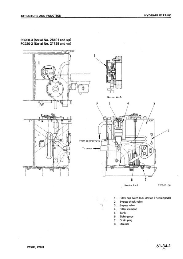
Hydraulic Tank….1494
Hydraulic Pump….1495
Line Oil Filter….1527
Control Valve….1528
Self-reducing Pressure Valve….1542
CLSS….1547
Swing Motor….1610
Center Swivel Joint….1616
Travel Motor….1618
Valve Control….1626
Work Equipment, Swing PPC Valve….1628
Travel PPC Valve….1636
Service PPC Valve….1640
Safety Lock Valve….1644
PPC Accumulator….1644
Straight-Travel System….1645
Solenoid Valve….1646
Boom Holding Valve….1648
Additional Filter for Breaker….1651
Swivel Joint for Arm Rotation….1653
Arm Rotation Motor….1654
Work Equipment….1656
Air Conditioner….1657
Actual Electric Wiring Diagram….1658
Electrical Circuit Diagram….1666
PC220-6 STD Serial No.: 96514 – 102228….1666
PC210-6 STD Serial No.: 30980 – 31424….1666
PC220-6 STD Serial No.: 52852 – 53561….1666
PC230-6 STD Serial No.: 10177 – 10246….1666
Engine Control System….1680
Electronic Control System for STD….1689
Electronic Control System for Hyper GX….1729
Machine Monitor System….1788
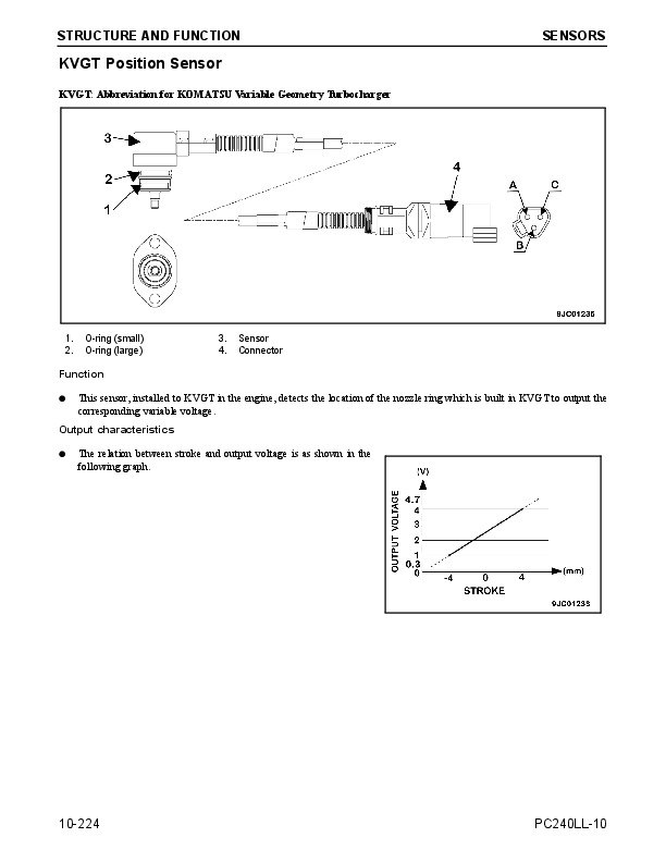
Sensors….1799
Front Window Auto Pull-up System….1802
20 TESTING AND ADJUSTING….1805
TABLE OF JUDGEMENT STANDARD VALUE….1808
TESTING AND ADJUSTING….1833
Tools for Testing, Adjusting, and Troubleshooting….1833
Measuring Engine Speed….1834
Measuring Exhaust Gas Color….1835
Adjusting Valve Clearance….1836
Measuring Compression Pressure….1837
Measuring Blow-by Pressure….1837
Testing and Adjusting Fuel Injection Timing….1838
Measuring Engine Oil Pressure….1839
Testing and Adjusting Alternator Belt Tension….1840
Testing and Adjusting Belt Tension for Air Conditioner Compressor….1840
Measuring Speed Sensor….1841
Testing and Adjusting Governor Motor Lever Stroke….1842
Testing and Adjusting Hydraulic Pressure in Work Equipment, Swing, Travel Circuit….1843
Testing and Adjusting PC Valve Output Pressure (Servo Piston Input Pressure)….1846
Testing and Adjusting LS Valve Output Pressure (Servo Piston Input Pressure) and LS Differential Pressure….1848
Testing and Adjusting Control Circuit Oil Pressure….1851
Testing Solenoid Valve Output Pressure….1853
Measuring PPC Valve Output Pressure….1855
Measuring EPC Solenoid Valve Output Pressure and Checking EPC Shuttle Valve….1857
Adjusting Work Equipment, Swing PPC Valve….1859
Testing Travel Deviation….1860
Testing Locations Causing Hydraulic Drift of Work Equipment….1861
Measuring Oil Leakage….1863
Releasing Remaining Pressure in Hydraulic Circuit….1865
Testing Clearance of Swing Circle Bearing….1866
Testing and Adjusting Track Shoe Tension….1867
Bleeding Air….1868
Input/Output Structure of GX Controller….1871
Basic Operation and GX Function….1872
Special Functions on GX Panel (Background Mode)….1874
Check Procedure when Operation of GX Automatic Function is Defective….1897
Adjusting Swing Back Prevention Function (Swing Teaching Mode)….1899
Bucket Dimension Input Mode when Using Custom Bucket….1901
Procedure for Replacing Sensor….1904
TROUBLESHOOTING….1910
Points to Remember When Troubleshooting….1911
Sequence of Events in Troubleshooting….1912
Precautions When Carrying Out Maintenance….1913
Checks Before Troubleshooting….1921
Connector Types and Mounting Locations….1923
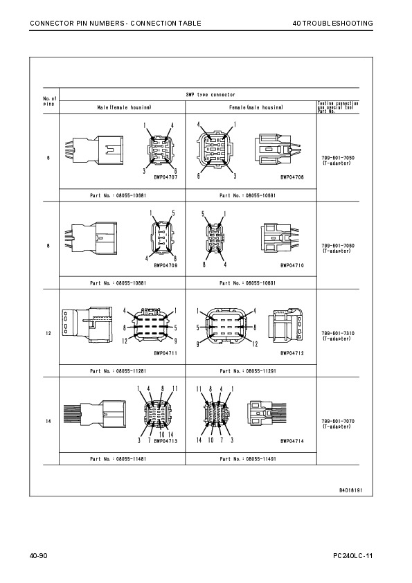
Connection Table for Connector Pin Numbers….1931
Explanation of Control Mechanism for Electrical System….1943
Display Method and Special Functions of Monitor Panel….1945
Method of Using Judgement Table….1955
Method of Using Troubleshooting Charts….1957
Details of Troubleshooting and Troubleshooting Procedure….1959
Troubleshooting of Communication Abnormality System ( N Mode)….1966
N-1 (E218) Communications Abnormality….1967
Troubleshooting of Engine Throttle – Pump Controller (Govenor Control System) (E Mode)….1970
Points to Remember When Carrying Out Troubleshooting of Engine Throttle – Pump Controller System….1971
Action Taken by Controller When Abnormality Occurs and Problems on Machine….1973
Judgement Table for Engine Throttle – Pump Controller (Govenor Control System) and Engine Related Parts….1977
Electrical Circuit Diagram for E Mode System….1979
E-1 Abnormality in Engine Throttle – Pump Controller Power Source (controller LED is OFF)….1981
E-2 (E308) Abnormality in Fuel Control Dial Imput Value is Displayed….1982
E-3 (E317) Abnormality (disconnection) in Motor Drive System is Displayed….1983
E-4 (E318) Abnormality (short circuit) in Motor Drive System is Displayed….1984
E-5 (E306) Abnormality in Feedback Potentionmeter System is Displayed….1985
E-6 (E315) Abnormality (short circuit) in Battery Relay Output System is Displayed….1986
E-7 (E316) Abnormality (step-out) in Motor is Displayed….1987
E-8 Engine Does Not Start….1989
E-9 Engine Speed is Irregular….1993
a) Idling Speed is Irregular….1993
b) There is Hunting….1995
E-10 Lack of Output (engine high idling speed is too low)….1997
E-11 Engine Does Not Stop….1999
E-12 Defective Operation of Battery Relay System (engine does not stop)….2001
Troubleshooting of Engine System (S Mode)….2004
Method of Using Troubleshooting Charts….2005
S-1 Starting Performance is Poor (starting always takes time)….2009
S-2 Engine Does Not Start….2010
(1) Engine Does Not Turn….2010
(2) Engine Turns But no Exhaust Smoke Comes Out (fuel is not being injected)….2011
(3) Exhaust Smoke Comes Out but Engine Does Not Start (fuel is being injected)….2012
S-3 Engine Does Not Pick Up Smoothly (follow-up is poor)….2013
S-4 Engine Stops During Operation….2014
S-5 Engine Does Not Rotate Smoothly (hunting)….2015
S-6 Engine Lacks Output ( no power)….2016
S-7 Exhaust Smoke is Black (incomplete combustion)….2017
S-8 Oil Consumption is Excessive (or exhaust smoke is blue)….2018
S-9 Oil Becomes Contaminated Quickly….2019
S-10 Fuel Consumption is Excessive….2020
S-11 Oil is in Cooling Water, or Water Spurts Back, or Water Level Goes Down….2021
S-12 Oil Pressure Caution Lamp Lights Up (drop in oil pressure)….2022
S-13 Oil Level Rises (water, fuel in oil)….2023
S-14 Water Temperature Becomes Too High (overheating)….2024
S-15 Abnormal Noise is Made….2025
S-16 Vibration is Excessive….2026
Troubleshooting of Engine Throttle – Pump Controller (Pump Control System) (C Mode)….2028
Points to Remember When Troubleshooting Pump Controller System….2029
Action Taken by Controller When Abnormality Occurs and Problems on Machine….2031
Judgement Table for Engine Throttle – Pump Controller (pump control system) and Hydraulic Related Parts….2039
Electrical Circuit Diagram for C Mode….2041
C-1 Abnormality in Controller Power Source System (controller LED is OFF)….2045
C-2 (E232) Short Circuit in PC-EPC Solenoid System is Displayed….2046
C-3 (E233) Disconnection in PC-EPC Solenoid System is Displayed….2047
C-4 (E203) Short Circuit in Swing Brake Solenoid System is Displayed….2048
C-5 (E213) Disconnection in Swing Brake Solenoid System is Displayed….2050
C-6 (E204) Short Circuit in Pump Merge/Divider Solenoid System is Displayed….2052
C-7 (E214) Disconnection in Pump Merge/Divider Solenoid System is Displayed….2053
C-8 (E207) Short Circuit In Active Mode Solenoid System is Displayed….2054
C-9 (E208) Disconnection in Active Mode Solenoid System is Displayed….2055
C-10 (E206) Short Circuit in Travel Speed Solenoid System is Displayed….2056
C-11 (E216) Disconnection in Travel Speed Solenoid System is Displayed….2057
C-12 (E205) Short Circuit in 2-Stage Relief Solenoid System is Displayed….2058
C-13 (E215) Disconnection in 2-State Relief Solenoid System is Displayed….2059
C-14 (E217) Model Selection Input Error is Displayed….2060
C-15 (E222) Short Circuit in LS-EPC Solenoid System is Displayed….2062
C-16 (E223) Disconnection in LS-EPC Solenoid System is Displayed….2063
C-17 (E224) Abnormality in Front Pump Pressure Sensor System is Displayed….2064
C-18 (E225) Abnormality in Rear Pump Pressure Sensor System is Displayed….2065
C-19 (E226) Abnormality in Pressure Sensor Power Source System is Displayed….2066
C-20 (E227) Abnormality in Engine Speed Sensor System is Displayed….2067
C-21 (E302) Short Circuit in Swing Stroke Limit Solenoid System is Displayed….2068
C-22 (E303) Disconnection in Swing Stroke Limit Solenoid System is Displayed….2069
Troubleshooting of Engine throttle – Pump Controller (Input Signal System) (F Mode)….2070
Electrical Circuit Diagram for F Mode….2071
F-1 Bit Pattern 20-(1) Swing Oil Pressure Switch Does Not Light Up….2075
F-2 Bit Pattern 20-(2) Travel Oil Pressure Switch Does Not Light Up….2076
F-3 Bit Pattern 20-(3) Boom LOWER Oil Pressure Switch Does Not Light Up….2077
F-4 Bit Pattern 20-(4) Boom RAISE Oil Pressure Switch Does Not Light Up….2078
F-5 Bit Pattern 20-(5) Arm IN Oil Pressure Switch Does Not Light Up….2079
F-6 Bit Pattern 20-(6) Arm OUT Oil Pressure Switch Does Not Light Up….2080
F-7 Bit Pattern 21-(1) Bucket CURL Oil Pressure Switch Does Not Light Up….2081
F-8 Bit Pattern 21-(2) Bucket DUMP Oil Pressure Switch Does Not Light Up….2082
F-9 Bit Pattern 21-(3) Swing Lock Switch Does Not Light Up….2083
F-10 Bit Pattern 22-(5) Kerosene Mode Connection Does Not Light Up….2084
F-11 Bit Pattern 22 (6) L.H. Knob Switch Does Not Light Up….2085
Troubleshooting of Hydraulic and Mechanical system (H Mode)….2086
Table of Failure Modes and Causes for Hydraulic and Mechnaical Systems ….2087
Pump Merge/Divider Logic….2091
Solenoid Actuation Table….2092
Troubleshooting Flow Charts for Each Failure Mode….2093
All Work Equipment, Travel, Swing….2093
H-1 Speeds of All Work Equipment, Swing, Travel Are Slow or Lack Power….2093
H-2 There is Excessive Drop in Engine Speed, or Engine Stalls….2095
H-3 No Work Equipment, Travel, Swing Move….2096
H-4 Abnormal Noise Generated (around pump)….2096
H-5 Auto-Deceleration Does Not work (PPC shuttle valve is euqipped only in travel PPC valve)….2097
H-6 Fine Control Ability is Poor or Response is Poor….2097
Work Equipment….2099
H-7 Boom is Slow or Lacks Power….2099
H-8 Arm is Slow or Lacks Power….2101
H-9 Bucket is Slow or Lacks Power….2103
H10- Work Equipment (boom, arm, bucket) Does Not Move (but travel and swing are normal)….2104
H-11 Excessive Hydraulic Drift….2104
H-12 Excessive Time Lag (engine at low idling)….2105
H-13 Other Equipment Moves When Single Circuit is Relieved….2105
H-14 Lack of Power When Pressure Rises….2106
H-15 In L/O, F/O Modes, Work Equipment Speed is Faster Than Specified Speed….2107
Compound Operations….2107
H-16 In Compound Operations, Work Equipment with Larger Load is Slow….2107
H-17 In Swing + Boom RAISE, Boom RAISE is Slow….2108
H-18 In Swing + Travel, Travel Speed Drops Excessively….2108
Travel System….2109
H-19 Travel Deviation….2109
H-20 Travel Speed is Slow….2111
H-21 Steering Does Not Turn Easily or Lacks Power….2113
H-22 Travel Speed Does Not Switch or is Faster than Specified Speed….2115
H-23 Travel Does Not Move (one side only)….2115
Swing System….2116
H-24 Does Not Swing….2116
H-25 Swing Acceleration is Poor or Swing Speed is Slow….2117
H-26 Excessive Overrun When Stopping Swing….2119
H-27 Excessive Shock When Stopping Swing (one direction only)….2120
H-28 Excessive Abnormal Noise When Stopping Swing….2120
H-29 Excessive Hydraulic Drift of Swing….2121
H-30 Swing Speed is Faster than Specified Speed in L/O and F/O Modes….2122
H-31 Operation of Automatic Mode is Defective (HYPER specification)….2122
Troubleshooting of Machine Monitor System (M Mode)….2124
Action Taken by Monitor Panel When Abnormality Occurs and Problems on Machine….2127
Electrical Circuit Diagram for M Mode System….2129
M-1 (E101) Abnormality in Error Data is Displayed….2131
M-1 (E102) Error in Clock Data is Displayed….2131
M-2 (E103) Short Circuit in Buzzer Output or Contact of 24V Wiring Harness with Buzzer Drive Harness is Displayed….2132
M-3 (E104) Air Cleaner Clogging Detected is Displayed….2133
M-4 (E108) Engine Water Temperature 105 degrees C Detected is Displayed….2133
M-5 When Starting Switch is Turned ON, None of Lamps on Monitor Panel Light Up for 3 Seconds….2134
a) None of Lamps on Monitor Panel Light Up….2134
b) Some of Lamps on Monitor Panel Do Not Light Up….2134
M-6 When Starting Switch is Turned ON, Monitor Panel Lamps All Stay Lighted Up and Do Not Go Out….2136
M-7 When Starting Switch is Turned ON, Items Lighted Up on Monitor Palen are Different from Actual Machine (Model)….2136
M-8 When Starting Switch is Turned ON (engine stopped), Basic Check Items Flash….2137
a) Coolant Level Flashes….2137
b) Engine Oil Level Flashes….2138
c) Hydraulic Oil Level Flashes….2139
M-9 Preheating is Not Being Used But Preheating Monitor Lights Up….2140
M-10 When Starting Switch is Turned ON and Engine is Started, Basic Check Items Flash….2141
a) Alternator System….2141
b) Engine Oil Pressure System….2142
M-11 When Starting Switch is Turned ON (engine stopped), Caution Items, Emergency Items Flash (battery, engine oil pressure l….2143
a) Alternator System….2143
b) Engine Oil Pressure Sensor System….2144
M-12 When Starting Switch is Turned ON and Engine is Started, Caution Items, Emergency Items Flash (when there is no abnormal….2145
a) Engine Oil Pressure Flashes….2145
b) Coolant Level Flashes….2145
c) Battery Charge Flashes….2145
d) Coolant Temperature Flashes….2146
e) Fuel Level Flashes….2146
f) Air Cleaner Clogging Flashes….2147
M-13 When Starting Switch is Turned ON (engine stopped), Buzzer Does Not Sound for 1 Second; Caution Item Flashes but Buzzer ….2148
M-14 No Abnormality is Displayed on Monitor but Buzzer Sounds….2148
M-15 Night Lighting on Monitor Panel Does Not Light Up (liquid crystal display is normal)….2149
M-16 Coolant Temperature Gauge Does Not Rise….2150
M-17 Coolant Temperature Gauge Does Not Give Any Display (none of gauge lamps light up during operation)….2150
M-18 Fuel Level Gauge Always Displays FULL….2151
M-19 Fuel Level Gauge Does Not Give Display….2151
M-20 Swing Lock Switch is Turned ON (LOCK) but Swing Lock Monitor Does Not Light Up….2152
M-21 Swing Prolix Switch is Turned ON (prolix), but Swing Lock Monitor Does Not Flash….2152
M-22 Service Meter Does Not Advance While Engine is Running….2153
M-23 When Starting Switch is at OFF and Time Switch is Pressed, Time and Service Meter Are Not Displayed….2153
M-24 Defective Fuel Level Sensor System….2154
M-25 Defective Coolant Temperature Sensor System….2155
M-26 Defective Engine Oil Level Sensor System….2156
M-27 Defective Coolant Level Sensor System….2157
M-28 Defective Hydraulic Oil Level Sensor System….2158
M-29 Wiper Does Not Work, or Switch is Not Being Used but Wiper is Actuated….2159
a) Wiper Does Not Work….2159
b) Wiper Switch is Not Being Operated but Wiper is Actuated….2162
M-30 Washer Motor Does Not Work, or Switch is Not Being Used but Washer Motor is Actuated….2164
a) Washer Motor Does Not Work….2164
b) Switch is Not Being Operated but Washer is Actuated….2165
Troubleshooting of GX Controller System (A Mode)….2166
Points to Remember When Troubleshooting GX Controller System….2168
Procedure for Troubleshooting Hyper GX….2169
Operation of GX Error Code Display Mode and Content of Display….2172
Action Taken by Controller When Abnormality Occurs, and Problems on Machine….2175
Electrical Wiring Diagram for GX Controller….2183
A-1 E6:01, E6:02, E6:03, and E6:04 are Displayed at the Same Time….2185
A-2 E6:01 (GX panel 011, 012) [Abnormality in Boom (RAISE) Pressure Sensor System] is Displayed….2187
A-3 E6:01 (GX panel 013, 014) [Abnormality in Boom (LOWER) Pressure Sensor System] is Displayed….2189
A-4 E6:02 (GX panel 021, 022) [Abnormality in Arm (IN) Pressure Sensor System] is Displayed….2191
A-5 E6:02 (GX panel 023, 024) [Abnormality in Arm (OUT) Pressure Sensor System] is Displayed….2193
A-6 E6:03 (GX panel 031, 032) [Abnormality in Bucket (CURL) Pressure Sensor System] is Displayed….2195
A-7 E6:03 (GX panel 033, 034) [Abnormality in Bucket (DUMP) Pressure Sensor System] is Displayed….2197
A-8 E6:04 (GX panel 041, 042) [Abnormality in Swing (RIGHT) Pressure Sensor System] is Displayed….2199
A-9 E6:04 (GX panel 043, 044) [Abnormality in Swing (LEFT) Pressure Sensor System] is Displayed….2201
A-10 E6:06 (GX panel 061, 063) [Abnormality in Clinometer Input Valve] is Displayed….2203
A-11 E6:07 and E6:08 [Abnormality in Potentiometer Power Source] are Displayed at the Same Time….2205
A-12 E6:07 (GX panel 071, 072) [Abnormality in Boom Potentionmeter System] is Displayed….2207
A-13 E6:08 (GX panel 081, 082) [Abnormality in Arm Potentiometer System] is Displayed….2209
A-14 E6:11 (GX panel 111, 112) [Abnormality in Boom Variable Angle] is Displayed….2211
A-15 E6:12 (GX panel 121, 122) [Abnormality in Arm Variable Angle] is Displayed….2213
A-16 E6:13 (GX panel 131, 132) [Abnormality in Bucket Variable Angle] is Displayed….2216
A-17 E6:14 (GX panel 141) [Abnormality in Comparision of Two Boom Sensor Signals] is Displayed….2217
A-18 E6:15 (GX panel 151) [Abnormality in Comparision of Two Arm Sensor Singals] is Displayed….2218
A-19 E6:16 (GX panel 163) [No Change in Signal When Work Equipment Should Move] is Displayed….2219
A-20 E6:17 (GX panel 171, 172) [Cutting Edge Position Out of Range] is Displayed….2220
A-21 E6:18 (GX panel 181, 182) [Abnormality in Data ROM] is Displayed….2220
A-22 E6:21 (GX panel 211, 212, 213, 214) [Abnromality in Engine Pick-up] is Displayed….2221
A-23 E6:22 (GX panel 221) [Change in Wiring Harness After Engine Picks up] is Displayed….2225
A-23 E6:22 (GX panel 222) [Automatic Operation Disconnection Switch Signal Does Not Match in Valve Controller and GX Control….2225
A-23 E6:22 (GX panel 223) [Abnormality in Controller Power Source] is Displayed….2225
A-24 E6:23 (GX panel 231) [Abnormality in Remote Singal] is Displayed….2229
A-24 E6:23 (GX panel 235) [Abnormality in 12V Power Source (overcurrent detection)] is Displayed….2229
A-24 E6:23 (GX panel 236) [Abnormality in 24V Power Source (overcurrent detection)] is Displayed….2229
A-25 E6:24 (GX panel 241) [Abnormality in Buzzer Drive System] is Diaplayed….2232
A-26 E6:25 (GX panel 251, 252) [Impossible to Receive Network (S-NET) Signal] is Displayed….2233
A-26 E6:25 (GX panel 253) [Impossible to Receive Network (HS-NET) Signal] is Displayed….2235
A-27 E6:26 (GX panel 261, 262, 263, 264) [Abnormality in Non-Volatile Memory Data Range] is Displayed….2238
A-28 E6:27 [Non-Volatile Read Error] is Displayed….2239
A-29 E6:28 [Non-Volatile Write Error] is Displayed….2239
A-30 Buzzer Does Not Sound (when there is no abnormal display)….2240
A-31 Automatic Mode is Not Actuated When Knob Switch is Pressed (when there is no abnormal display….2241
Troubleshooting of Valve Controller System (K Mode)….2242
Points to Remember When Troubleshooting Valve Controller System….2244
Action Taken by Controller When Abnormality Occurs and Problems on Machine….2245
Judgement Table for Valve Controller System….2263
Electrical Circuit Diagram of Valve Controller System….2265
K-1 [LED OFF] Controller Power Source System….2268
K-2 [E4:02] L.H. Knob Switch OFF System is Displayed….2269
K-3 [E4:07] Abnormality in Model Code Input is Displayed….2270
K-4 [E4:51] Abnormality in S-NET Communication is Displayed….2271
1. Disconnection Related….2271
2. Short Circuit Related….2273
K-5 [E4:56] Abnormality in Teaching, Playback RAM Data is Displayed….2273
K-6 [E4:57] Abnormality in Knob Switch is Displayed….2274
K-7 [E4:01] Abnormality in Control Lever Neutral System is Displayed….2275
K-8 [E4:04] Abnormality in Control Lever Potentiometer Power Source System is Displayed….2277
K-9 [E4:11) Short Circuit in EPC Relay 1 Drive Power Source System is Displayed….2278
K-10 [E4:12] Contact Between Chassis Power Source and EPC Relay 1 Drive Power Source System is Displayed….2279
K-11 [E4:13] Short Circuit in EPC Relay 2 Drive Power Source System is Displayed….2280
K-12 [E4:14] Contact Between Chassis Power Source and EPC Relay 2 Drive Power Source System is Displayed….2281
K-13 [E4:15] Disconnection in EPC Relay 1,2 Solenoid Power Source System is Displayed….2282
K-14 [E4:16] EPC Relay 1 Points Melted or Short Circuit in Solenoid Power Source System is Displayed….2284
K-14 [E4:17] EPC Relay 2 Points Melted or Short Circuit in Solenoid Power Source System is Displayed….2284
1) When E4:16 is Displayed Independently….2284
2) When E4:16, E4:17 are Displayed Simultaneously….2284
K-15 [E4:17] EPC Relay 2 Points Melted or Short Circuit in Solenoid Power Source System is Displayed….2286
K-15 [E4:16] EPC Relay 1 Points Melted or Short Circuit in Solenoid Power Source System is Displayed….2286
1) When E4:17 is Displayed Independently….2286
2) When E4:16, E4:17 are Displayed Simultaneously….2286
K-16 [E4:18] Abnormality in Lever Signal Input Delay Circuit System is Displayed….2288
K-17 [E4:21] Abnormality 1 in Drive Circuit System for Boom LOWER EPC Valve is Displayed….2289
K-17 [E4:25] Abnormality 1 in Drive Circuit System for Boom RAISE EPC Valve is Displayed….2289
K-17 [E4:21] [E4:31] Abnormality 1,2 in Drive Circuit System for Boom LOWER EPC Valve is Displayed….2291
K-17 [E4:25] [E4:35] Abnormality 1,2 in Drive Circuit System for Boom RAISE EPC Valve is Displayed….2291
K-18 [E4:31 Abnormality 2 in Drive Circuit System for Boom LOWER EPC Valve is Displayed….2293
K-18 [E4:35] Abnormality 2 in Drive Circuit System for Boom RAISE EPC Valve is Displayed….2293
K-18 [E4:21] [E4:31] Abnormality 1,2 in Drive Circuit System for Boom LOWER EPC Valve is Displayed….2295
K-18 [E4:25] [E4:35} Abnormality 1,2 in Drive Circuit System for Boom RAISE EPC Valve is Displayed….2295
K-19 [E4:32} Abnormality 2 in Drive Circuit System for Arm IN EPC Valve is Displayed….2297
K-19 [E4:33] Abnormality 2 in Drive Circuit System for Bucket CURL EPC Valve is Displayed….2297
K-19 [E4:34] Abnormality 2 in Drive Circuit System for Swing LEFT EPC Valve is Displayed….2297
K-19 [E4:36] Abnormality 2 in Drive Circuit System for Arm OUT LEFT EPC Valve is Displayed….2297
K-19 [E4:37] Abnormality 2 in Drive Circuit System for Bucket DUMP EPC Valve is Displayed….2297
K-19 [E4:38] Abnormality 2 in Drive Circuit System for Swing RIGHT EPC Valve is Displayed….2297
K-19 [E4:22] [E4:32] Abnormality 1,2 in Drive Circuit System for Arm IN EPC Valve is Displayed….2299
K-19 [E4:23] [E4:33] Abnormality 1,2 in Drive Circuit System for Bucket CURL EPC Valve is Displayed….2299
K-19 [E4: 24] [E4:34] Abnormality 1,2 in Drive Circuit System for Swing LEFT EPC Valve is Displayed….2299
K-19 [E4:26] [E4:36] Abnormality 1,2 in Drive Circuit System for Arm OUT EPC Valve is Displayed….2299
K-19 [E4:27] [E4:37] Abnormality 1,2 in Drive Circuit System for Bucket DUMP EPC Valve is Displayed….2299
K-19 [E4:28] [E4:38] Abnormality 1,2 in Drive Circuit System for Swing RIGHT EPC Valve is Displayed….2299
K-20 [E4:41] [E4:42] [E4:43] [E4:44} Over-range in Control Lever Potentiometer Signal System is Displayed….2301
K-21 [E4:45] [E4:46] [E4:47] [E4:48] Excessive Error in Signal SIG and Switch SIG of Control Lever Potentiometer is Displayed….2303
K-22 [E4:55] Abnormality in ROM, RAM of CPU is Displayed….2305
K-23 [E4:58] Abnormality in Interlock PLD is Displayed….2305
K-24 [E4:22] Abnormality 1 in Drive Circuit System for Arm IN EPC Valve is Displayed….2306
K-24 [E4:23] Abnormality 1 in Drive Circuit System for Bucket CURL EPC Valve is Displayed….2306
K-24 [E4:24] Abnormality 1 in Drive Circuit System for Swing LEFT EPC Valve is Displayed….2306
K-24 [E4:26] Abnormality 1 in Drive Circuit System for Arm OUT EPC Valve is Displayed….2306
K-24 [E4:27] Abnormality 1 in Drive Circuit System for Bucket DUMP EPC Valve is Displayed….2306
K-24 [E4:28] Abnormality 1 in Drive Circuit System for Swing RIGHT EPC Valve is Displayed….2306
K-24 [E4:22] [E4:32] Abnormality 1,2 in Drive Circuit System for Arm IN EPC Valve is Displayed….2308
K-24 [E4:23] [E4:33] Abnormality 1,2 in Drive Circuit System for Bucket CURL EPC Valve is Displayed….2308
K-24 [E4:24] [E4:34] Abnormality 1,2 in Drive Circuit System for Swing LEFT EPC Valve is Displayed….2308
K-24 [E4:26] [E4:36] Abnormality 1,2 in Drive Circuit System for Arm OUT EPC Valve is Displayed….2308
K-24 [E4:27] [E4:37] Abnormality 1,2 in Drive Circuit System for Bucket DUMP EPC Valve is Displayed….2308
K-24 [E4:28] [E4:38] Abnormality 1,2 in Drive Circuit System for Swing RIGHT EPC Valve is Displayed….2308
30 DISASSEMBLY AND ASSEMBLY….2310
Method of Using Manual….2312
Precautions When Carrying Out Operation….2313
Special Tool List….2315
Sketches of Special Tools….2323
Starting Motor….2326
Removal of Starting Motor Assembly….2326
Installation of Starting Motor Assembly….2326
Alternator….2327
Removal of Alternator Assembly….2327
Installation of Alternator Assembly….2328
Air Conditioner Compressor….2330
Removal of Air Conditioner Compressor Assembly….2330
Installation of Air Conditioner Compressor Assembly….2330
Condenser….2331
Removal of Condenser Assembly….2331
Installation of Condenser Assembly….2331
Air Conditioner Condenser ….2332
Removal of Air Conditioner Condenser Assembly….2332
Installation of Air Conditioner Condenser Assembly….2332
Dry Receiver….2333
Removal of Dry Receiver Assembly….2333
Installation of Dry Receiver Assembly….2333
Engine Oil Cooler Core….2334
Removal of Engine Oil Cooler Core Assembly….2334
Installation of Engine Oil Cooler Core Assembly….2334
Fuel Injection Pump….2335
Removal of Fuel Injection Pump Assembly….2335
Installation of Fuel Injection Pump Assembly….2338
Water Pump….2345
Removal of Water Pump Assembly….2345
Installation of Water Pump Assembly….2346
Nozzle Holder….2347
Removal of Nozzle Holder Assembly….2347
Installation of Nozzle Holder Assembly….2347
Turbocharger….2348
Removal of Turbocharger Assembly….2348
Installation of Turbocharger Assembly….2348
Thermostat….2349
Removal of Thermostat Assembly….2349
Installation of Thermostat Assembly….2350
Govenor Motor….2351
Removal of Govenor Motor Assembly….2351
Installation of Governor Motor Assembly….2351
Cylinder Head….2352
Removal of Cylinder Head Assembly….2352
Installation of Cylinder Head Assembly….2358
Hydraulic Oil Cooler….2369
Removal of Hydraulic Oil Cooler Assembly….2369
Installation of Hydraulic Oil Cooler Assembly….2369
Radiator – Hydraulic Oil Cooler….2371
Removal of Radiator, Hydraulic Oil Cooler Assembly….2371
Installation of Radiator, Hydraulic Oil Cooler Assembly….2373
Engine – Main Pump….2377
Removal of Engine, Main Pump Assembly….2377
Installation of Engine, Main Pump Assembly….2381
Damper….2382
Removal of Damper Assembly….2382
Installation of Damper Assembly….2382
Fuel Tank….2383
Removal of Fuel Tank Assembly….2383
Installation of Fuel Tank Assembly….2383
Center Swivel Joint….2384
Removal of Center Swivel Joint Assembly….2384
Installation of Center Swivel Joint Assembly….2385
Disassembly of Center Swivel Joint Assembly….2386
Assembly of Center Swivel Joint Assembly….2386
Final Drive….2387
Removal of Final Drive Assembly….2387
Installation of Final Drive Assembly….2387
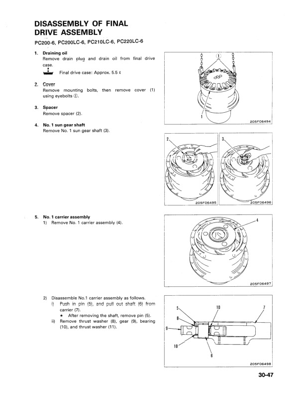
Disassembly of Final Drive Assembly….2388
Assembly of Final Drive Assembly….2391
Travel Motor….2396
Disassembly of Travel Motor Assembly….2396
Assembly of Travel Motor Assembly….2402
Sprocket….2410
Removal of Sproket….2410
Installation of Sprocket….2410
Swing Motor and Swing Machinery….2411
Removal of Swing Motor, Swing Machinery Assembly….2411
Installation of Swing Motor, Swing Machinery Assembly….2412
Disassembly of Swing Machinery Assembly….2413
Assembly of Swing Machinery Assembly….2417
Swing Motor….2422
Disassembly of Swing Motor Assembly….2422
Assembly of Swing Motor Assembly….2426
Revolving Frame….2434
Removal of Revolving Frame Assembly….2434
Installation of Revolving Frame Assembly….2435
Swing Circle….2436
Removal of Swing Circle Assembly….2436
Installation of Swing Circle Assembly….2437
Idler – Recoil Spring….2438
Removal of Idler – Recoil Spring Assembly….2438
Installation of Idler – Recoil Spring Assembly….2438
Recoil Spring….2439
Disassembly of Recoil Spring Assembly….2439
Assembly of Recoil Spring Assembly….2440
Idler….2441
Disassembly of Idler Assembly….2441
Assembly of Idler Assembly….2442
Track Roller….2444
Removal of Track Roller Assembly….2444
Installation of Track Roller Assembly….2444
Disassembly of Track Roller Assembly….2445
Assembly of Track Roller Assembly….2447
Carrier Roller….2449
Removal of Carrier Roller Assembly….2449
Installation of Carrier Roller Assembly….2449
Disassembly of Carrier Roller Assembly….2450
Assembly of Carrier Roller Assembly….2452
Track Shoe….2454
Removal of Track Shoe Assembly….2454
Installation of Track Shoe Assembly….2454
Hydraulic Tank….2455
Removal of Hydraulic Tank Assembly….2455
Installation of Hydraulic Tank Assembly….2456
Main Pump….2457
Removal of Main Pump Assembly….2457
Installation of Main Pump Assembly….2459
Disassembly of Main Pump Assembly….2461
Assembly of Main Pump Assembly….2474
Main Pump Input Shaft Oil Seal….2490
Removal of Main Pump Input Shaft Oil Seal….2490
Installation of Main Pump Input Shaft Oil Seal….2490
Control Valve….2491
Removal of Control Valve Assembly….2491
Installation of Control Valve Assembly….2493
Disassembly of Control Valve Assembly….2494
Assembly of Control Valve Assembly….2499
Pump Merge-Divider Valve….2505
Disassembly of Pump Merge-Divider Valve Assembly….2505
Assembly of Pump Merge-Divider Valve Assembly….2505
Main Relief Valve….2506
Disassembly of Main Relief Valve Assembly….2506
Assmebly of Main Relief Valve Assembly….2506
Work Equipment EPC Valve….2507
Removal of Work Equipment EPC Valve Assembly….2507
Installation of work Equipment EPC Valve Assembly….2507
PC Valve….2508
Removal of PC Valve Assembly….2508
Installation of PC Valve Assembly….2509
LS Valve ….2510
Removal of LS Valve Assembly….2510
Installation of LS Valve Assembly….2510
PC, LS-EPC Valve….2511
Removal of PC, LS-EPC Valve Assembly….2511
Installation of PC, LS-EPC Valve Assembly….2511
Solenoid Valve….2512
Removal of Solenoid Valve Assembly….2512
Installation of Solenoid Valve Assembly….2512
Work Equipment – Swing PPC Valve….2513
Removal of Work Equipment – Swing PPC Valve Assembly….2513
Installation of Work Equipment – Swing PPC Valve Assembly….2513
Disassembly of Work Equipment – Swing PPC Valve Assembly….2514
Assembly of Work Equipment – Swing PPC Valve Assembly….2515
Travel PPC Valve….2516
Removal of Travel PPC Valve Assembly….2516
Installation of Travel PPC Valve Assembly….2516
Disassembly of Travel PPC Valve Assembly….2517
Assembly of Travel PPC Valve Assembly….2518
Boom Lock Valve….2519
Removal of Boom Lock Valve Assembly….2519
Installation of Boom Lock Valve Assembly….2519
Boom Cylinder….2520
Removal of Boom Cylinder Assembly….2520
Installation of Boom Cylinder Assembly….2521
Arm Cylinder….2522
Removal of Arm Cylinder Assembly….2522
Installation of Arm Cylinder Assembly….2523
Bucket Cylinder….2524
Removal of Bucket Cylinder Assembly….2524
Installation of Bucket Cylinder Assembly….2525
Hydraulic Cylinder….2526
Disassembly of Hydraulic Cylinder Assembly….2526
Assembly of Hydraulic Cylinder Assembly….2529
Work Equipment….2533
Removal of Work Equipment Assembly….2533
Installation of Work Equipment Assembly….2534
Bucket….2535
Removal of Bucket Assembly….2535
Installation of Bucket Assembly….2536
Arm….2537
Removal of Arm Assembly….2537
Installation of Arm Assembly….2538
Bucket – Arm….2539
Removal of Bucket – Arm Assembly….2539
Installation of Bucket – Arm Assmebly….2540
Boom….2541
Removal of Boom Assembly….2541
Installation of Boom Assembly….2542
Opeator's Cab….2543
Removal of Operator's Cab Assembly….2543
Installation of Operator's Cab Assembly….2544
Counterweight….2545
Removal of Counterweight Assembly….2545
Installation of Counterweight Assembly….2545
Work Equipment Electric Lever Unit….2547
Removal of Work Equipment Electric Lever Unit Assembly….2547
Installation of Work Equipment Electric Lever Unit Assembly….2547
Engine Throttle – Pump Controller….2548
Removal of Engine Throttle – Pump Controller Assembly….2548
Installation of Engine Throttle – Pump Controller Assembly….2548
Control Stand Case….2549
Removal of Control Stand Case….2549
Installation of Control Stand Case….2550
Valve Controller….2551
Removal of Valve Controller Assembly….2551
Installation of Valve Controller Assembly….2551
Monitor….2552
Removal of Monitor Assembly….2552
Installation of Monitor Assembly….2552
ITERMS FOR HYPER GX….2553
Swing Motor….2553
Removal of Swing Motor Assembly….2553
Installation of Swing Motor Assembly….2553
Control Valve….2554
Removal of Control Valve Assembly….2554
Installation of Control Valve Assembly….2555
Work Equipment EPC Valve….2556
Removal of Work Equipment EPC Valve Assembly….2556
Installation of Work Equipment EPC Valve Asembly….2556
Boom Cylinder….2557
Removal of Boom Cylinder Assembly….2557
Installation of Boom Cylinder Assembly….2558
Arm Cylinder….2559
Removal of Arm Cylinder Assembly….2559
Installation of Arm Cylinder Assembly….2560
Bucket Cylinder….2561
Removal of Bucket Cylinder Assembly….2561
Installation of Bucket Cylinder Assembly….2562
Disassembly of Bucket Cylinder Assembly….2563
Assembly of Bucket Cylinder Assembly….2565
Work Equipment….2569
Removal of Work Equipment Assembly….2569
Installation of Work Equipment Assembly….2571
Bucket….2572
Removal of Bucket Assembly….2572
Installation of Bucket Assembly….2573
Arm….2574
Removal of Arm Assembly….2574
Installation of Arm Assembly….2575
Bucket – Arm….2576
Removal of Bucket – Arm Assembly….2576
Installation of Bucket – Arm Assembly….2577
Boom….2578
Removal of Boom Assembly….2578
Installation of Boom Assembly….2580
Valve Controller….2581
Removal of Valve Controller Assembly….2581
Installation of Valve Controller Assembly….2581
GX Controller….2582
Removal of GX Controller Assembly….2582
Installation of GX Controller Assembly….2582
GX Panel….2583
Removal of GX Panel Assembly….2583
Installation of GX Panel Assembly….2583
40 MAINTENANCE STANDARD….2584
Swing Machinery….2585
Swing Circle….2587
Final Drive….2589
Track Frame – Recoil Spring….2591
Idler….2593
Carrier Roller….2595
Track Roller….2596
Track Shoe….2597
Hydraulic Pump….2603
Control Valve….2604
Safety-Suction Valve (for Service Valve)….2617
Self-Reducing Pressure Valve….2618
Swing Motor….2619
Travel Motor….2620
Work Equipment – Swing PPC Valve….2621
Work Equipment – Swing EPC Valve….2622
Tavel PPC Valve….2623
Service PPC Valve….2624
EPC Solenoid Valve….2625
Center Swivel Joint….2626
Boom Holding Valve….2628
Hydraulic Cylinder….2629
Work Equipment….2635
Dimension of Work Equipment….2641
90 OTHER….2648
Hydraulic Circuit Diagram (pg. 90-3)….2649
PC200-6 STD Serial No.: 96514 – 102228….2649
PC210-6 STD Serial No.: 30980 – 31424….2649
PC220-6 STD Serial No.: 52852 – 53561….2649
PC230-6 STD Serial No.: 10177 – 10246….2649
Hydraulic Circuit Diagram (pg. 90-5)….2650
PC200-6 STD Serial No.: 102229 and UP….2650
PC210-6 STD Serial NO.: 31425 and UP….2650
PC220-6 STD Serial No.: 53562 and UP….2650
PC230-6 STD Serial NO.: 10247 and UP….2650
Hydraulic Circuit Diagram (pg. 90-7)….2651
PC200-6 HYPER GX Serial No.: 96514 – 102228….2651
Hydraulic Circuit Diagram (pg. 90-9)….2652
PC200-6 HYPER GX Serial No.: 102229 and UP….2652
Hydraulic Circuit Diagram (pg. 90-10-1)….2653
For Rotary Arm = PC200, 200LC-6….2653
Electrical Circuit Diagram [ 1/2 ] (pg. 90-11)….2654
PC200-6 STD Serial No.: 96514 – 102228….2654
PC210-6 STD Serial No.: 30980 – 31424….2654
PC220-6 STD Serial No.: 52852 – 53561….2654
PC230-6 STD Serial No.: 10177 – 10246 ….2654
Electrical Circuit Diagram [ 2/2 ] (pg. 90-13)….2655
PC200-6 STD Serial No.: 96514 – 102228….2655
PC210-6 STD Serial No.: 30980 – 31424….2655
PC220-6 STD Serial NO.: 52852 – 53561….2655
PC230-6 STD Serial No.: 10177 – 10246….2655
Electrical Circuit Diagram [1/2 ] (pg. 90-15)….2656
PC200-6 STD Serial No.: 102229 and UP….2656
PC210-6 STD Serial No.: 31425 and UP….2656
PC220-6 STD Serial No.: 53562 and UP….2656
PC230-6 STD Serial No.: 10247 and UP….2656
Electrical Circuit Diagram [ 2/2 ] (pg. 90-17)….2657
PC200-6 STD Serial No.: 102229 and UP….2657
PC210-6 STD Serial No.: 31425 and UP….2657
PC220-6 STD Serial No.: 53562 and UP….2657
PC230-6 STD Serial No.: 10247 and UP….2657
Electrical Circuit Diagram [ 1/3 ] (pg. 90-19)….2658
PC200-6 HYPER GX Serial No.: 94999 – 102228….2658
Electrical Circuit Diagram [ 2/3 ] (pg. 90-21)….2659
PC200-6 HYPER GX Serial No.: 94999 – 102228….2659
Electrical Circuit Diagram [ 3/3 ] (pg. 90-23)….2660
PC200-6 HYPER GX Serial No.: 94999 – 102228….2660
Electrical Circuit Diagram (pg. 90-25)….2661
PC200-6 HYPER GX Serial No.: 94999 – 102228….2661
Electrical Circuit Diagram [ 1/3 ] (pg. 90-27)….2662
PC200-6 HYPER GX Serial No.: 102229 and UP….2662
Electrical Circuit Diagram [ 2/3 ] (pg. 90-29)….2663
PC200-6 HYPER GX Serial No.: 102229 and UP….2663
Electrical Circuit Diagram [ 3/3 ] (pg. 90-31)….2664
PC200-6 HYPER GX Serial No.: 102229 and UP….2664
Electrical Circuit Diagram (pg 90-33)….2665
PC200-6 HYPER GX Serial No.: 102229 and UP….2665

Komatsu Hydraulic Excavator PC200, PC200LC, PC210, PC210LC, PC220, PC220LC, PC230, PC230LC Repair Service Manuals


INSTANT DOWNLOAD


Posted on

Komatsu Log Loader Road Builder PC240LL-10 Repair Service Manual


INSTANT DOWNLOAD


Complete service repair manual with Electrical Wiring Diagrams for Komatsu Log Loader Road Builder PC240LL-10, with all the technical information to maintain, diagnose, repair, rebuild like professional mechanics.

Komatsu Log Loader Road Builder PC240LL-10 workshop service repair manual includes:
* Numbered table of contents easy to use so that you can find the information you need fast.
* Detailed sub-steps expand on repair procedure information
* Numbered instructions guide you through every repair procedure step by step.
* Troubleshooting and electrical service procedures are combined with detailed wiring diagrams for ease of use.
* Notes, cautions and warnings throughout each chapter pinpoint critical information.
* Bold figure number help you quickly match illustrations with instructions.
* Detailed illustrations, drawings and photos guide you through every procedure.
* Enlarged inset helps you identify and examine parts in detail.

PRODUCT DETAILS:
Total Pages: 345 pages
File Format: PDF
Language: English

CEBM028500 – Log Loader Road Builder PC240LL-10 Shop Manual.pdf

MAIN SECTIONS
CEBM028500 PC240LL-10 S/N A20601 & Up…1
CONTENTS…2
00 – FOREWORD …3
SAFETY…3
Safety Notice…3
Important Safety Notice…3
General Precautions…3
Preparations For Work…4
Precautions During Work…4
GENERAL…7
HOW TO READ THE SHOP MANUAL…8
Volumes…8
Distribution And Updating…8
Filing Method…8
Revised Edition Mark…8
Revisions…8
Symbols…8
HOISTING INSTRUCTIONS…9
Hoisting…9
Making Signs…9
Precautions…9
Precautions for Sling Work…9
Precautions for Using Mobile Crane…10
Precautions for Using Overhead Hoist Crane…10
Selecting Wire Ropes…11
HANDLING ELECTRIC EQUIPMENT AND HYDRAULIC COMPONENTS…12
Points to Remember When Handling Electric Equipment…12
Points to Remember When Handling Hydraulic Equipment…23
PUSH PULL COUPLER…25
Type 1…25
Disconnection…25
Connection…25
Type 2…26
Disconnection…26
Connection…26
Type 3…27
Disconnection…27
Connection…27
EXPLANATION OF MAINTENANCE STANDARD TERMS…28
HANDLING OF FUEL SYSTEM DEVICES…29
HANDLING OF INTAKE SYSTEM PARTS…30
STANDARD TIGHTENING TORQUE…31
Bolts And Nuts…31
Tightening Torque Of Hose Nuts…32
Tightening Torque Of Split Flange Bolts…32
Tightening Torque For Flared Nuts…32
Tightening Torques for Split Flanged Bolts…33
Tightening Torques For O-ring Boss Piping Joints…33
Table Of Tightening Torques For O-ring Boss Plugs…33
Tightening Torque For Hoses (Taper Seal Type And Face Seal Type)…34
Tightening Torque For Face Seal Joints…34
For 102, 107, and 114 Engine Series (Bolts and Nuts)…34
For 102, 107, and 114 Engine Series (Eye Joints)…35
For 102, 107, and 114 Engine Series (Taper Screws)…35
ELECTRIC WIRE CODE…36
Classification By Thickness…36
Classification By Color And Code…36
How To Read Electric Wire Code…37
PRECAUTIONS FOR OPERATIONS…40
Precautions when Carrying Out Removal Work…40
Precautions when Carrying Out Installation Work…41
Precautions when Completing the Operation…42
CONVERSION TABLES…43
Method Of Using The Conversion Table…43
COATING MATERIALS…49
LIST OF ABBREVIATIONS…52
List of Abbreviations Used in the Shop Manual…52
List of Abbreviations Used in the Circuit Diagrams…56
01 – GENERAL…57
SPECIFICATIONS…58
Dimension Drawings…58
Road Builder…58
Log Loader…58
Dimensions…59
Working Ranges…61
Road Builder…61
Log Loader…62
Engine…63
Undercarriage…63
Hydraulic System…64
Road Builder…64
Log Loader…65
WEIGHT TABLE…66
FUEL, COOLANT AND LUBRICANTS…68
Lubrication Chart…70
10 – STRUCTURE AND FUNCTION…71
ENGINE AND COOLING SYSTEM…74
Engine Related Parts…74
Radiator, Oil Cooler, Aftercooler, and Fuel Cooler…76
POWER TRAIN…78
Power Train…78
Swing Machinery…80
Swing Circle…82
Final Drive…84
UNDERCARRIAGE AND FRAME…86
Track Frame and Idler Cushion…86
HYDRAULIC SYSTEM…88
Hydraulic Equipment Layout…88
Valve Control…90
Hydraulic Tank…92
Oil Filler Cap…93
CLSS…94
Structure of CLSS…94
Basic Principle…95
Main Pump…98
Operation…102
LS Valve…104
PC Valve…110
LS(PC)-EPC Valve…117
Control Valve…120
Functions and Operation by Valve…132
Hydraulic Circuit Diagram and Name of Valves…132
Unload Valve…135
Introduction of LS Pressure…136
LS By-Pass Plug…137
Pressure Compensation Valve…138
Shuttle Valve In Pressure Compensation Valve…141
Boom Regeneration Circuit…143
Arm Regeneration Circuit…145
Merge-Divider Valve…147
LS Selector Valve…150
Self-Pressure Reducing Valve…151
Travel Junction Valve…154
Travel PPC Shuttle Valve…157
Boom Hydraulic Drift Prevention Valve…159
Arm Hydraulic Drift Prevention Valve (Road Builder)…162
Arm Drift Prevention Valve (Log Loader)…165
Operation…166
Suction Safety Valve For Drift Prevention Valve…168
Arm Quick Return Valve…169
Variable Back Pressure Valve…171
Main Relief Valve…173
Swing Motor…174
Swing Holding Brake…176
Relief Valve…178
Swing 2-Stage Relief Valve…180
Swing Motor Reverse Prevention Valve…181
Travel Motor…184
Operation of Travel Motor…187
Operation of Parking Brake…189
Brake Valve…190
Counterbalance Valve…191
Suction Safety Valve…192
PPC Valve…196
Work Equipment and Swing PPC Valve…196
Travel PPC Valve…201
Solenoid Valve…206
Attachment Solenoid Valve…209
Center Swivel Joint…211
Accumulator…213
PPC Accumulator…213
WORK EQUIPMENT…214
Road Builder…214
Log Loader…215
Work Equipment Shim…216
Bucket Play Adjustment Shim (Road Builder)…216
CAB AND ITS ATTACHMENTS…217
ELECTRICAL SYSTEM…219
Electrical Control System…219
Machine Control System Diagram…219
Engine Control Function…221
Engine and Pump Combined Control Function…223
Pump and Valve Control Function…229
One-Touch Power Maximizing Function…231
Auto-Deceleration Function…233
Engine Automatic Warm-Up Function…235
Overheat Prevention Function…237
Turbocharger Protection Function…238
Swing Control Function…239
Quick Warm-Up Function…243
Swing 2-Stage Relief Function…243
Travel Control Function…244
PPC Lock Function…246
Attachment Flow Control Function…247
System Component Part…249
Engine Controller…249
Pump Controller…253
Fuel Control Dial…256
Resister for PC-EPC valve…257
CAN Terminating Resistor…258
Engine Oil Pressure Switch…259
PPC Oil Pressure Switch…260
MACHINE MONITOR SYSTEM…261
Machine Monitor…263
Input and Output Signals…264
Display…266
Gauges…268
Caution Monitor…270
Pilot Monitor…273
Switches…275
Guidance ICON and Function Switch…277
Operator Mode Function…280
Service Mode Function…282
KOMTRAX SYSTEM…283
KOMTRAX terminal…284
Input and Output Signals…285
SENSORS…287
Ambient Pressure Sensor…287
Charge (Boost) Pressure and Temperature Sensor…288
Coolant Temperature Sensor…289
Ne (Crankshaft) Speed Sensor…289
Bkup (Camshaft) Speed Sensor…290
Common Rail Pressure Sensor…290
Exhaust Manifold Pressure Sensor…291
EGR Orifice Temperature Sensor…291
EGR Valve Lift Sensor…292
Turbo Speed Sensor…293
KVGT Position Sensor…294
Mass Air Flow and Temperature Sensor…295
KDPF Differential Pressure and Outlet Pressure Sensor…295
KDOC Inlet Temperature Sensor…296
KDOC Outlet Temperature Sensor…296
KDPF Outlet Temperature Sensor…297
Crankcase Pressure Sensor…297
Engine Oil Level Sensor…298
Fuel Level Sensor…299
Coolant Level Sensor…300
Hydraulic Oil Temperature Sensor…300
Front Pump Oil Pressure Sensor…301
Rear Pump Oil Pressure Sensor…302
PPC Oil Pressure Sensor…303
Air Cleaner Clogging Sensor…304
Front Pump Swash Plate Sensor…305
Rear Pump Swash Plate Sensor…307
Water-In-Fuel Sensor…309
20 – STANDARD VALUE TABLES…311
STANDARD SERVICE VALUE TABLES…312
Standard Value Table for Engine Related Parts…312
Standard Value Table for Chassis Related Parts…314
Engine Speed…314
Control Valve Spool Stroke…314
Control Lever Stroke…315
Operating Effort of Control Lever and Pedal…315
Hydraulic Pressure…316
Swing…317
Travel…318
Work Equipment…319
Performance in Combined Operation…321
Pump Swash Plate Sensor…321
Hydraulic Pump…322
Posture of Machine for Measuring Performance and Measurement Procedure…323
Control Valve: Spool Stroke…323
Swing 1: Overrun When Stopping Swing, Time Taken to Start Swing, Time Taken to Swing…323
Swing 2: Hydraulic Drift of Swing…323
Travel 1: Travel Speed, Idle Running (Without Load)…324
Travel 2: Travel Speed (Actual Run), Travel Deviation…324
Travel 3: Travel Deviation…325
Travel 4: Hydraulic Drift of Travel…325
Work Equipment 1: Hydraulic Drift of Work Equipment…326
Work Equipment 2: Boom Speed…326
Work Equipment 3: Arm Speed…326
Work Equipment 4: Bucket Speed/Heel Speed…327
Work Equipment 5: Boom Time Lag…327
Work Equipment 6: Arm Time Lag…328
Work Equipment 7: Bucket Time Lag…328
90 – DIAGRAMS AND SCHEMATICS…329
HYDRAULIC SYSTEM…331
Symbols in Hydraulic Circuit Diagrams…331
Hydraulic Circuit Diagram (1/2)…332
Hydraulic Circuit Diagram (2/2)…333
ELECTRICAL SYSTEM…334
Symbols in Electrical Circuit Diagrams…334
Air Conditioner Electrical Circuit…335
Electrical Control System Diagram…336
Electrical Diagram (1/5)…337
Electrical Diagram (2/5)…338
Electrical Diagram (3/5)…339
Electrical Diagram (4/5)…340
Electrical Diagram (5/5)…341
Electrical Circuit Diagram – Log Loader Unique…342
Connector List and Stereogram…343
Chassis…343
Operator's Compartment…344
Engine Compartment…345

Komatsu Log Loader Road Builder PC240LL-10 Repair Service Manual


INSTANT DOWNLOAD


Posted on

Komatsu Hydraulic Excavator PC240LC Repair Service Manuals


INSTANT DOWNLOAD


Complete service repair manual with Electrical Wiring Diagrams for Komatsu Hydraulic Excavator PC240LC, with all the technical information to maintain, diagnose, repair, and rebuild like professional mechanics.

Komatsu Hydraulic Excavator PC240LC-10 workshop service repair manual includes:
* Numbered table of contents easy to use so that you can find the information you need fast.
* Detailed sub-steps expand on repair procedure information
* Numbered instructions guide you through every repair procedure step by step.
* Troubleshooting and electrical service procedures are combined with detailed wiring diagrams for ease of use.
* Notes, cautions and warnings throughout each chapter pinpoint critical information.
* Bold figure number help you quickly match illustrations with instructions.
* Detailed illustrations, drawings and photos guide you through every procedure.
* Enlarged inset helps you identify and examine parts in detail.

CEAM025102 – Hydraulic Excavator PC240LC-10 Operation & Maintenance Manual.pdf
CEBM024902 – Hydraulic Excavator PC240LC-10 Shop Manual.pdf
CEBM028601 – Hydraulic Excavator PC240LC-11 Shop Manual.pdf
SEN05538-02 – Hydraulic Excavator PC240LC-10 Shop Manual.pdf
TEN00509-02 – Hydraulic Excavator PC240LC-10 Operation & Maintenance Manual.pdf
TEN00592-01 – Hydraulic Excavator PC240LC-10 Operation & Maintenance Manual.pdf

Total Pages: 7,273 pages
File Format: PDF
Language: English

CEAM025102 – Hydraulic Excavator PC240LC-10 Operation & Maintenance Manual…2
FORWARD…7
SAFETY INFORMATION…8
Safety Labels…9
INTRODUCTION…10
Directions of Machine…10
Visibility from Operator’s Seat…10
Structure to Protect the Operator…10
Breaking-in The New Machine…11
Product Information…12
Product Identification Number (Pin)/Machine Serial No. Plate…12
EPA* Regulations, Engine Number Plate…12
Service Meter Location…13
Your Machine Serial Numbers And Distributor…13
Engine Acronyms…13
TABLE OF CONTENTS…14
SAFETY LABELS…25
Location Of Safety Labels…25
Safety Labels…26
GENERAL PRECAUTIONS COMMON TO OPERATION AND MAINTENANCE…35
Precautions Before Starting Operation…35
Ensuring Safe Operation…35
Understanding The Machine…35
Preparations For Safe Operation…35
Precautions Regarding Safety-related Equipment…35
Inspecting Machine…35
Clothing And Personal Protective Items…35
Keep Machine Clean…36
Keep Operator's Compartment Clean…36
Fire Extinguisher And First Aid Kit…36
Safety Equipment…36
If Problems Are Found…36
Fire Prevention And Explosion Prevention…37
Action If Fire Occurs…38
Handrails and Steps…39
Mounting And Dismounting…39
No Persons On Attachments…39
Leaving Operator's Seat With Lock…40
Emergency Exit From Operator's Cab…40
Do Not Get Caught In Work Equipment…41
Precautions Related To Protective Structures…41
Falling Objects, Flying Objects And Intruding Objects Prevention…41
Unauthorized Modification…42
Precautions Related To Attachments And Options…42
Precautions Related To Cab Glass…42
Precautions When Running Engine Inside Building…42
Safety At Jobsite…43
Working On Loose Ground…43
Distance To High Voltage Cables…43
Ensure Good Visibility…44
Signalman's Signal And Signs…44
Asbestos Dust Hazard Prevention…45
SAFETY MACHINE OPERATION…46
Starting Engine…46
Checks Before Starting Engine…46
Safety Rules For Starting Engine…47
Starting Engine In Cold Weather…47
Starting Engine With Booster Cables…47
Operation…48
Checks Before Operation…48
Safety Rules For Changing Machine Directions…48
Safety Rules For Traveling…49
Traveling On Slopes…50
Operations On Slopes…51
Prohibited Operations…52
Operations On Snow Or Frozen Surfaces…54
Parking Machine…54
TRANSPORTATION…55
Loading and Unloading…55
Shipping the Machine…55
TOWING…56
Safety Rules For Towing…56
LIFTING OBJECTS WITH BUCKET…57
Safety Rules For Lifting Objects…57
SAFETY MAINTENANCE INFORMATION…58
Warning Tag…58
Keep Work Place Clean And Tidy…58
Select Suitable Place For Inspection And Maintenance…58
Only Authorized Personnel…58
Appoint Leader When Working With Others…58
Stop Engine Before Carrying Out Maintenance…59
Precautions When Working At High Places…59
Two Workers For Maintenance When Engine Is Running…60
Attachments…60
Work On Machine…61
Work Under The Machine…61
Proper Tools…61
Battery Disconnect Switch…62
Removing Battery Terminals…62
Welding…62
Battery…62
Battery Hazard Prevention…62
When Using Hammer…63
Precautions With High-temperature Coolant…63
Precautions With High-temperature Oil…64
Safety Rules For High-pressure Oil…64
Precaution For High Fuel Pressure…64
Safety Handling High-pressure Hoses or Piping…64
Precaution For High Voltage…65
Noise…65
Safety First When Using High-pressure Grease To Adjust Track Tension…65
Do Not Disassemble Recoil Springs…66
Accumulator…66
Handling Gas Spring…66
Precautions when using…66
Precautions when discarding…67
Compressed Air…67
Air Conditioner Maintenance…67
Waste Materials…67
Select Window Washer Fluid…67
Personnel…67
Periodic Replacement Of Safety Critical Parts…68
MACHINE VIEW ILLUSTRATIONS…71
Overall Machine View…71
General View of Cab…73
CONTROLS AND GAUGES…74
Machine Monitor…75
EXPLANATION OF COMPONENTS…76
Machine Monitor…76
Basic Operation of Machine Monitor…77
Warning Display…82
Meter Display…92
Gauges and Meter…99
Monitor Switches Portion…102
Handling Function Switches…112
User Menu Selector Switch…116
User Menu…117
Machine Settings…128
Maintenance Screen Setting…133
Monitor Setting…135
Screen Adjustment…135
Screen Adjustment (Camera)…136
Clock Adjustment…136
Time…138
SWITCHES…143
Starting Switch…143
Fuel Control Dial…144
Cigarette Lighter…144
Swing Lock Switch…144
Lamp Switch…145
Horn Switch…145
One Touch Power Max. Switch…145
Room Lamp Switch…145
Emergency Pump Drive Switch…146
Swing Brake Cancel Switch…146
Ceiling Window Wiper Switch…147
Seat Heater Switch…147
Engine Shutdown Secondary Switch…148
CONTROL LEVERS AND PEDALS…149
Lock Lever…149
Travel Levers…150
Work Equipment Control Lever…151
ROOF WINDOW…153
WINDSHIELD…153
EMERGENCY ESCAPE HAMMER…159
DOOR LOCK…160
CAB DOOR HINGE…160
ENGINE HOOD…161
When Opening (Normal Case: Intermediate Lock Position)…161
When Closing (Normal Case: Intermediate Lock Position)…163
CAPS AND COVERS WITH LOCK…165
Open and Close Caps with Lock…165
Opening the Cap…165
Locking the Cap…165
Open and Close Covers with Lock…166
Opening the Cover (Locked Cover)…166
Locking the Cover…166
Lock and Unlock Engine Hood…166
Opening the Hood (Locked Hood)…166
Locking the Hood…166
Lock and Unlock Cab Door…167
Opening the Door (Locked Door)…167
Locking the Door…167
DRINK BOX…168
MAGAZINE BOX…168
CUP HOLDER…168
ASHTRAY…169
AIR CONDITIONER CONTROLS…170
Air Conditioner Control Panel…170
Method of Operation…175
Automatic Operation…175
Stopping Automatic Operation…176
Manual Operation…176
Stop Manual Operation…178
Operation with Cold Air to Face and Warm Air to Feet…178
Defroster Operation…180
Rules for Using Air Conditioner…182
Air Conditioner Maintenance…182
RADIO…183
Control Panel…183
Operation Method…185
Frequency Adjustment…185
Frequency Adjustment (Auto Presetting)…185
Preset Call…185
Preset Memory…185
Sound Adjustment (Balance)…185
Sound Adjustment (Treble)…186
Sound Adjustment (Bass)…186
Time Adjustment…186
Stowing Radio Antenna…186
AUXILIARY ELECTRIC POWER…187
24 V Power Source…187
12 V Power Source…187
FUSE…188
FUSIBLE LINK…189
TOOL BOX…189
GREASE GUN HOLDER…189
FIRE EXTINGUISHER…189
BATTERY DISCONNECT SWITCH…190
SYSTEM OPERATING LAMP…191
HANDLING KOMATSU DIESEL PARTICULATE FILTER (KDPF)…192
Operation Procedure of Manual Stationary Regeneration…195
Komatsu Diesel Particulate Filter (KDPF) Regeneration Disable Procedure…197
While Regeneration is not being Performed: Setting for Regeneration Disable…198
While Regeneration is being Performed: Stopping Regeneration…200
Komatsu Diesel Particulate Filter (KDPF) Regeneration Disable Cancel Procedure…201
Handling Komatsu Closed Crankcase Ventilation (KCCV)…201
HANDLING MACHINES EQUIPPED WITH KOMTRAX…202
Basic Precautions…203
MACHINE OPERATIONS AND CONTROLS…204
Before Starting Engine…204
Walk-around Checks…204
Checks Before Starting…206
Adjustment…215
Seat Belt Inspection…224
Seat Belt…225
Operations Before Starting Engine…226
STARTING ENGINE…228
Turbo Protect Function…231
AFTER STARTING ENGINE…232
Engine Warm Up…234
Hydraulic System Warm-Up…236
Operation After Completion Of Warming-Up Operation…242
STOPPING THE ENGINE…244
MACHINE OPERATION…245
Preparations for Moving the Machine…245
Moving Machine Forward…246
Moving Machine Backward…247
Stopping Machine…248
STEERING THE MACHINE…249
Steering…249
Steering the Machine when Stopped…249
Changing Direction of the Machine…250
Counter-rotation Turn (Spin Turn)…250
SWINGING…251
WORK EQUIPMENT CONTROLS AND OPERATIONS…252
WORKING MODE…254
Working Mode Switch…254
One-Touch Power Max. Switch…256
PROHIBITED OPERATIONS…257
GENERAL OPERATION INFORMATION…260
Traveling…260
High Speed Travel…260
Permissible Water Depth…261
TRAVELING ON SLOPES…262
ESCAPE FROM MUD…264
Track on One Side Stuck…264
Tracks on Both Sides Stuck…264
RECOMMENDED APPLICATIONS…265
Backhoe Work…265
Shovel Work…265
Ditching Work…265
Loading Work…266
BUCKET REPLACEMENT AND INVERSION…267
Replacement…267
Inversion…269
PARKING MACHINE…271
MACHINE INSPECTION AFTER DAILY WORK…273
LOCKING…273
TRANSPORTATION…273
Transportation Procedure…273
Loading And Unloading With Trailer…274
Loading…275
Securing Machine…278
Stowing Radio Antenna…280
Rear view Mirrors…280
Remove and Install Handrail…282
Unloading…283
LONG DISTANCE TRANSPORT MODE…285
Normal Mode Display…285
Long Distance Transport Mode Display…285
LIFTING MACHINE…287
Standard Specification Machines…287
Machines with Lifting Hook…289
COLD WEATHER OPERATION…290
Cold Weather Operation Information…290
Fuel and Lubricants…290
Coolant…290
Battery…291
AFTER DAILY WORK COMPLETION…292
AFTER COLD WEATHER SEASON…292
LONG TERM STORAGE…293
Before Storage…293
During Storage…293
After Storage…294
Starting Machine After Long-term Storage…294
TROUBLES AND ACTIONS…295
Running Out Of Fuel…295
Phenomena That Are Not Failures…295
Towing The Machine…296
Lightweight Towing Hole…297
Severe Job Condition…297
Discharged Battery…298
Battery Removal and Installation…298
Battery Charges…299
Starting Engine with Booster Cables…300
OTHER TROUBLE…302
Electrical System…302
Chassis…303
Engine…304
Electronic Control System…306
Point of Contact to Telephone when Error Occurs…306
MAINTENANCE INFORMATION…309
OUTLINE OF SERVICE…311
Handling Oil, Fuel, Coolant, And Performing Oil Clinic…311
Oil…311
Fuel…312
Coolant And Water For Dilution…312
Grease…313
Carrying Out KOWA (Komatsu Oil Wear Analysis)…313
Storing Oil And Fuel…314
Filters…314
Electric System Maintenance…314
WEAR PARTS…315
Wear Parts List…315
RECOMMENDED FUEL, COOLANT, AND LUBRICANT…316
Lubrication Chart…316
Fuel, Coolant, and Lubricants to Match the Ambient Temperature…318
KDPF (Komatsu Diesel Particulate Filter)…318
Recommended Brands, Recommended Quality For Products Other Than Komatsu Genuine Oil…319
TORQUE SPECIFICATIONS…320
Torque List…320
Torque Of Bolts…320
Torque Of Hose Nuts…321
Torque Of Split Flange Bolts…321
Torque For Flared Nuts…322
Torque For O-ring Boss Piping Joints…322
Torque For O-ring Boss Plugs…323
Torque For Hoses (Taper Seal Type And Face Seal Type)…323
SAFETY CRITICAL PARTS…325
Safety Critical Parts List…326
MAINTENANCE SCHEDULE…327
Maintenance Schedule Table…327
Maintenance Interval For Hydraulic Breaker…329
MAINTENANCE PROCEDURE…330
Initial 10 Hours Maintenance…330
Initial 250 Hours Maintenance (Only After The First 250 Hours)…330
Initial 500 Hours Maintenance (Only After The First 500 Hours)…330
When Required…331
Check, Clean And Replace Air Cleaner Element…331
Clean Inside Of Cooling System…338
Check And Tighten Track Shoe Bolts…343
Check And Adjust Track Tension…344
Replace Bucket Teeth (Vertical Pin Type)…346
Replace Bucket Teeth (Horizontal Pin Type)…349
Replace Bucket Side Cutter, Shroud…351
Adjust Bucket Clearance…352
Check Window Washer Fluid Level, Add Fluid…353
Check And Maintain Air Conditioner…354
Wash Washable Floor…355
Set Machine at Angle…357
Check Gas Spring…358
Bleeding Air From Hydraulic System…359
Check Before Starting…361
Every 100 Hours Maintenance…362
Lubricating…362
Every 250 Hours Maintenance…363
Check Level Of Battery Electrolyte…363
Check Air Conditioner Compressor Belt Tension, Adjust…365
Every 500 Hours Maintenance…367
Lubricating…367
Change Oil In Engine Oil Pan…369
Replace Engine Oil Filter Cartridge…369
Replace Fuel Pre-filter Cartridge…371
Check Swing Pinion Grease Level, Add Grease…373
Clean And Inspect Radiator Fins, Oil Cooler Fins, Aftercooler Fins, Fuel Cooler Fins, And Condenser Fins…374
Clean Air Conditioner Fresh/Recirc Filters…376
Replace Breather Element In Hydraulic Tank…378
Check Oil Level In Swing Machinery Case, Add Oil…379
Check Oil Level In Final Drive Case, Add Oil…380
Every 1000 Hours Maintenance…381
Replace Hydraulic Oil Filter Element…381
Change Oil In Swing Machinery Case…382
Check Oil Level In Damper Case, Add Oil…383
Replace Fuel Main Filter Cartridge…384
Check All Tightening Points Of Engine Exhaust Pipe Clamps…387
Check Fan Belt Tension And Replace Fan Belt…387
Check Nitrogen Gas Charge Pressure In Accumulator (For Breaker)…387
Every 2000 Hours Maintenance…388
Change Oil In Final Drive Case…388
Clean Hydraulic Tank Strainer…389
Check Charge Pressure Of Nitrogen Gas In Accumulator (For Control Circuit)…390
Check Alternator…393
Check Engine Valve Clearance, Adjust…393
Replace Komatsu Closed Crankcase Ventilation (KCCV) Filter Element…394
Every 4000 Hours Maintenance…397
Check Water Pump…397
Check Vibration Damper…397
Check Starting Motor…397
Replace Accumulator (For Control Circuit)…398
Check For Looseness Of High-pressure Piping Clamp, Hardening Of Rubber…399
Check For Missing Fuel Spray Prevention Cap, Hardening Of Rubber…399
Check Operating Condition Of Compressor…400
Every 4500 Hours Maintenance…401
Clean Komatsu Diesel Particulate Filter (KDPF)…401
Replace Komatsu Closed Crankcase Ventilation (KCCV) Hose…401
Every 5000 Hours Maintenance…402
Change Oil In Hydraulic Tank…402
Every 8000 Hours Maintenance…403
Replace Fuel Spray Prevention Cap…403
Replace High-pressure Piping Clamp…403
SPECIFICATIONS…405
GENERAL PRECAUTIONS FOR SAFETY…409
Precautions When Selecting…409
Read The Operation and Maintenance Manual Thoroughly…409
Precautions When Removing Or Installing…409
Precautions When Using…409
BUCKET WITH HOOK…410
Hook Condition…410
Prohibited Operations…410
CHANGING DIRECTION OF THE MACHINE…411
Straight Travel (Option)…412
CHANGING MACHINE CONTROL PATTERN…413
Control Pattern Change Procedure…413
MACHINE READY FOR ATTACHMENT…415
Locations…415
Stop Valve…415
Selector Valve…416
Attachment Control Pedal…416
Lock Pin…416
Breaker Circuit Additional Oil Filter…417
Accumulator…418
HYDRAULIC CIRCUIT…419
Switching Hydraulic Circuit…419
Switching Between Breaker and General Attachment…419
Hydraulic Circuit Connection…420
Oil Flow Path…421
Replace Additional Breaker Filter Element…422
Replace Additional Breaker Pilot Filter Element…425
ATTACHMENT REMOVAL AND INSTALLATION…428
Attachment Removal…428
Attachment Installation…430
ATTACHMENT OPERATIONS…432
When Using Breaker…432
When Using General Attachment Such as Crusher…435
LONG TERM STORAGE…436
Specifications…436
Attachment Guide…437
Attachment Combinations…437
TRACK SHOES SELECTION…439
BUCKET TEETH SELECTION…440
Selection Guide for Horizontal or Vertical Pin Type Tooth…440
HANDLING OF RUBBER PAD SHOE AND ROAD LINER…441
Check Road Liner…442
Handling Trapezoidal Bucket…443
Digging Work…443
HANDLING EXTENSION ARM…445
HANDLING CLAMSHELL BUCKET…446
RECOMMENDED ATTACHMENT OPERATIONS…447
Hydraulic Breaker…447
Prohibited Usage…449
CEBM024902 – Hydraulic Excavator PC240LC-10 Shop Manual…452
CEBM024902_PC240LC-10…0
CONTENTS…453
00 – FOREWORD…470
GENERAL…474
HOW TO READ THE SHOP MANUAL…475
Volumes…475
Distribution And Updating…475
Filing Method…475
Revised Edition Mark…475
Revisions…475
Symbols…475
HOISTING INSTRUCTIONS…476
Hoisting…476
Making Signs…476
Precautions…476
Precautions for Sling Work…476
Precautions for Using Mobile Crane…477
Precautions for Using Overhead Hoist Crane…477
Selecting Wire Ropes…478
HANDLING ELECTRIC EQUIPMENT AND HYDRAULIC COMPONENTS…479
Points to Remember When Handling Electric Equipment…479
Points to Remember When Handling Hydraulic Equipment…490
PUSH PULL COUPLER…492
Type 1…492
Disconnection…492
Connection…492
Type 2…493
Disconnection…493
Connection…493
Type 3…494
Disconnection…494
Connection…494
EXPLANATION OF MAINTENANCE STANDARD TERMS…495
HANDLING OF FUEL SYSTEM DEVICES…496
HANDLING OF INTAKE SYSTEM PARTS…497
STANDARD TIGHTENING TORQUE…498
Bolts And Nuts…498
Tightening Torque Of Hose Nuts…499
Tightening Torque Of Split Flange Bolts…499
Tightening Torque For Flared Nuts…499
Tightening Torques for Split Flanged Bolts…500
Tightening Torques For O-ring Boss Piping Joints…500
Table Of Tightening Torques For O-ring Boss Plugs…500
Tightening Torque For Hoses (Taper Seal Type And Face Seal Type)…501
Tightening Torque For Face Seal Joints…501
For 102, 107, and 114 Engine Series (Bolts and Nuts)…501
For 102, 107, and 114 Engine Series (Eye Joints)…502
For 102, 107, and 114 Engine Series (Taper Screws)…502
ELECTRIC WIRE CODE…503
Classification By Thickness…503
Classification By Color And Code…503
How To Read Electric Wire Code…504
PRECAUTIONS FOR OPERATIONS…507
Precautions when Carrying Out Removal Work…507
Precautions when Carrying Out Installation Work…508
Precautions when Completing the Operation…509
CONVERSION TABLES…510
Method Of Using The Conversion Table…510
COATING MATERIALS…516
LIST OF ABBREVIATIONS…519
List of Abbreviations Used in the Shop Manual…519
List of Abbreviations Used in the Circuit Diagrams…523
Safety Notice…470
Important Safety Notice…470
General Precautions…470
Preparations For Work…471
Precautions During Work…471
01 – GENERAL…524
SPECIFICATION DIMENSION DRAWINGS…525
Dimensions…525
Working Ranges…526
SPECIFICATIONS…527
WEIGHT TABLE…531
FUEL, COOLANT AND LUBRICANTS…533
Lubrication Chart…535
10 – STRUCTURE AND FUNCTION…0
ENGINE AND COOLING SYSTEM…539
Engine Related Parts…539
Radiator, Oil Cooler, Aftercooler, and Fuel Cooler…541
POWER TRAIN…543
Power Train…543
Swing Machinery…545
Swing Circle…547
Final Drive…549
UNDERCARRIAGE AND FRAME…551
Track Frame and Idler Cushion…551
HYDRAULIC SYSTEM…553
Hydraulic Equipment Layout…553
Valve Control…555
Hydraulic Tank…557
Oil Filler Cap…558
CLSS…559
Structure of CLSS…559
Basic Principle…560
Main Pump…563
Operation…567
LS Valve…569
PC Valve…575
LS(PC)-EPC Valve…582
Control Valve…585
Functions and Operation by Valve…597
Hydraulic Circuit Diagram and Name of Valves…597
Unload Valve…601
Introduction of LS Pressure…602
LS By-Pass Plug…603
Pressure Compensation Valve…604
Shuttle Valve In Pressure Compensation Valve…607
Boom Regeneration Circuit…609
Arm Regeneration Circuit…611
Merge-Divider Valve…613
LS Selector Valve…616
Self-Pressure Reducing Valve…617
Travel Junction Valve…621
Travel PPC Shuttle Valve…625
Boom Hydraulic Drift Prevention Valve…627
Arm Hydraulic Drift Prevention Valve (If Equipped)…630
Suction Safety Valve For Drift Prevention Valve…633
Arm Quick Return Valve…635
Variable Back Pressure Valve…637
Main Relief Valve…639
Suction 2-Stage Safety Valve…641
Swing Motor…643
Swing Holding Brake…645
Relief Valve…647
Swing 2-Stage Relief Valve…649
Swing Motor Reverse Prevention Valve…650
Travel Motor…653
Operation of Travel Motor…656
Operation of Parking Brake…658
Brake Valve…659
Counterbalance Valve…660
Suction Safety Valve…661
PPC Valve…663
Work Equipment and Swing PPC Valve…663
Travel PPC Valve…669
1st-Line Attachment PPC Valve (with EPC Valve) (If Equipped)…673
EPC Valve (If Equipped)…675
2nd-Line Attachment PPC Valve (If Equipped)…679
Solenoid Valve…681
Attachment Circuit Selector Valve (For High Pressure Circuit) (If Equipped)…685
Attachment Circuit Selector Valve (For Low Pressure Circuit) (If Equipped)…687
Center Swivel Joint…689
Accumulator…690
PPC Accumulator…690
WORK EQUIPMENT…691
Work Equipment…691
Work Equipment Shim…692
Bucket Play Adjustment Shim…692
CAB AND ITS ATTACHMENTS…693
Cab Mount and Cab Tipping Stopper…693
ROPS Cab…695
ELECTRICAL SYSTEM…697
Electrical Control System…697
Machine Control System Diagram…697
Engine Control Function…699
Engine and Pump Combined Control Function…701
Pump and Valve Control Function…707
One-Touch Power Maximizing Function…709
Auto-Deceleration Function…711
Engine Automatic Warm-Up Function…713
Overheat Prevention Function…715
Turbocharger Protection Function…716
Swing Control Function…717
Quick Warm-Up Function…719
Swing 2-Stage Relief Function…719
Travel Control Function…721
PPC Lock Function…723
Attachment Flow Control Function…725
System Component Part…727
Engine Controller…727
Pump Controller…731
Fuel Control Dial…735
Resister for PC-EPC valve…736
CAN Terminating Resistor…737
Engine Oil Pressure Switch…738
PPC Oil Pressure Switch…739
MACHINE MONITOR SYSTEM…741
Machine Monitor…743
Input and Output Signals…744
Display…747
Gauges…749
Caution Monitor…751
Pilot Monitor…755
Switches…757
Guidance ICON and Function Switch…759
Operator Mode Function…763
Service Mode Function…765
KOMTRAX SYSTEM…767
KOMTRAX terminal…768
Input and Output Signals…769
SENSORS…771
Ambient Pressure Sensor…771
Charge (Boost) Pressure and Temperature Sensor…772
Coolant Temperature Sensor…773
Ne (Crankshaft) Speed Sensor…773
Bkup (Camshaft) Speed Sensor…774
Common Rail Pressure Sensor…774
Exhaust Manifold Pressure Sensor…775
EGR Orifice Temperature Sensor…775
EGR Valve Lift Sensor…776
Turbo Speed Sensor…777
KVGT Position Sensor…778
Mass Air Flow and Temperature Sensor…779
KDPF Differential Pressure and Outlet Pressure Sensor…779
KDOC Inlet Temperature Sensor…780
KDOC Outlet Temperature Sensor…780
KDPF Outlet Temperature Sensor…781
Crankcase Pressure Sensor…781
Engine Oil Level Sensor…782
Fuel Level Sensor…783
Coolant Level Sensor…784
Hydraulic Oil Temperature Sensor…784
Front Pump Oil Pressure Sensor…785
Rear Pump Oil Pressure Sensor…786
PPC Oil Pressure Sensor…787
Air Cleaner Clogging Sensor…788
Front Pump Swash Plate Sensor…789
Rear Pump Swash Plate Sensor…791
Water-In-Fuel Sensor…793
20 – STANDARD VALUE TABLES…0
STANDARD SERVICE VALUE TABLES…795
Standard Value Table for Engine Related Parts…795
Standard Value Table for Chassis Related Parts…797
Engine Speed…797
Control Valve Spool Stroke…797
Control Lever Stroke…798
Operating Effort of Control Lever and Pedal…798
Hydraulic Pressure…799
Swing…800
Travel…801
Work Equipment…802
Performance in Combined Operation…804
Pump Swash Plate Sensor…804
Characteristics of PC Flow Control…804
Hydraulic Pump…805
Posture of Machine for Measuring Performance and Measurement Procedure…806
Control Valve: Spool Stroke…806
Swing 1: Overrun When Stopping Swing, Time Taken to Start Swing, Time Taken to Swing…806
Swing 2: Hydraulic Drift of Swing…806
Travel 1: Travel Speed, Idle Running (Without Load)…806
Travel 2: Travel Speed (Actual Run), Travel Deviation…807
Travel 3: Travel Deviation…807
Travel 4: Hydraulic Drift of Travel…807
Work Equipment 1: Hydraulic Drift of Work Equipment…807
Work Equipment 2: Boom Speed…808
Work Equipment 3: Arm Speed…808
Work Equipment 4: Bucket Speed…808
Work Equipment 5: Boom Time Lag…808
Work Equipment 6: Arm Time Lag…809
Work Equipment 7: Bucket Time Lag…809
Work Equipment 8: PC Flow Characteristics Control…809
30 – TESTING AND ADJUSTING…0
GENERAL INFORMATION ON TESTING AND ADJUSTING…813
Tools for Testing, Adjusting, and Troubleshooting…813
Sketch of Tools for Testing and Adjusting…818
ENGINE AND COOLING SYSTEM…821
Checking Engine Speed…821
Measuring Boost Pressure…823
Measuring Exhaust Gas Color…825
Measuring and Adjusting Valve Clearance…827
Testing…827
Adjusting…830
Measuring Compression Pressure…831
Measuring Blow-By Pressure…837
Measuring Engine Oil Pressure…839
Measuring EGR Valve and KVGT Oil Pressure…841
Measuring Fuel Pressure…843
Testing Low-Pressure Circuit (Fuel Main Filter Inlet Side)…845
Testing Low-Pressure Circuit (Pressure Difference)…846
Testing Return Circuit…847
Testing Negative-Pressure Circuit…848
Measuring Fuel Delivery, Return and Leakage…849
Testing Supply Pump Delivery…851
Testing Supply Pump Return Rate…853
Testing Leakage from Pressure Limiter…854
Testing Injector Return Rate from Injector…855
Bleeding Air from Fuel System…857
Bleeding Air…857
Route for Bleeding Air from Fuel Circuit…858
Checking Fuel Circuit for Leakage…859
Handling Cylinder Cut-Out Mode Operation…860
Handling No-Injection Cranking Operation…860
Checking and Adjusting Air Conditioner Compressor Belt Tension…861
Checking…861
Adjusting…862
Replacing Fan Belt…863
POWER TRAIN…865
Testing Swing Circle Bearing Clearance…865
Testing…865
UNDERCARRIAGE AND FRAME…867
Testing and Adjusting Track Shoe Tension…867
Testing…867
Adjusting…867
HYDRAULIC SYSTEM…869
Releasing Remaining Pressure from Hydraulic Circuit…869
Measuring and Adjusting of Oil Pressure in Work Equipment, Swing, and Travel Circuits…871
Testing…871
Adjusting…873
Measuring Oil Pressure in Control Circuit…875
Measuring and Adjusting Oil Pressure in Pump PC Control Circuit…877
Testing…877
Adjusting…880
Measuring and Adjusting Oil Pressure in Pump LS Control Circuit…881
Testing…882
Checking Oil Pressure with Sensor Adapter (Special Tool)…886
Adjusting…887
Measuring Solenoid Valve Output Pressure…889
Testing…889
Operating Condition…891
Measuring PPC Valve Output Pressure…893
Adjusting Play of Work Equipment and Swing PPC Valves…895
Testing Pump Swash Plate Sensor…896
Isolating the Parts Causing Hydraulic Drift in Work Equipment…897
Measuring Oil Leakage…899
Bleeding Air From Hydraulic Circuit…902
CAB AND ITS ATTACHMENTS…905
Checking Cab Tipping Stopper…905
Adjusting Mirrors…907
ELECTRICAL SYSTEM…909
Special Functions of Machine Monitor…909
Upper Part of Machine Monitor (Display Portion)…910
Upper Part of Machine Monitor (Switch Portion)…910
Lower Part of Machine Monitor (Switch Portion)…910
Ordinary Functions and Special Functions of Machine Monitor…910
Operator Mode (Outline)…913
Display of KOMATSU Logo…915
Display of Inputting Password…915
Display of Check of Breaker Mode…915
Display of Check Before Starting…916
Display of Warning After Check Before Starting…916
Display of Ending of Maintenance Interval…916
Display of Check of Working Mode and Travel Speed…916
Display of Standard Screen…917
Display of End Screen…917
Display of Engine Shutdown Secondary Switch Screen…917
Selection of Auto-Deceleration…917
Selection of Working Mode…918
Selection of Travel Speed…919
Operation to Stop Alarm Buzzer…919
Operation of Windshield Wiper…919
Operation of Window Washer…919
Operation of Air Conditioner/Heater…919
Operation to Display Camera Mode (If Camera is Installed)…920
Operation to Display Clock and Service Meter…920
Check of Maintenance Information…921
Setting and Display of User Mode (Including KOMTRAX Messages for User)…921
Display of ECO Guidance…922
Display of Caution Monitor…923
Display of KDPF Regeneration…925
Display of Action Level and Failure Code…928
Function of Checking Display of LCD (Liquid Crystal Display)…929
Function of Checking Service Meter…929
Function of Changing Attachment/Maintenance Password…931
Service Mode…933
Monitoring / Pre-Defined…935
Monitoring / Custom…941
Monitoring Items Table…945
Abnormality Record (Mechanical Systems)…951
Abnormality Record (Electrical Systems)…953
Maintenance Record…955
Maintenance Mode Setting…957
Phone Number Entry…960
Default (Key-On Mode)…961
Default (Unit)…962
Default (With/Without Attachment)…963
Default (Camera)…965
Diagnostic Tests (Cylinder Cut-out)…967
Diagnostic Tests (Regeneration for Service)…969
Diagnostic Tests (KDPF Memory Reset)…971
Adjustment (Pump Absorption Torque (F))…973
Adjustment (Pump Absorption Torque (R))…974
Adjustment (Low Speed)…975
Adjustment (Attachment Flow Adjustment)…976
Adjustment (Cal F Pump Swash Plate Sensor)…977
Adjustment (Cal R Pump Swash Plate Sensor)…983
Adjustment (Pump Calibration: Matching Speed Calibration)…984
Adjustment (Pump Calibration: Matching Speed Check)…986
No Injection…993
KOMTRAX Settings (Terminal Status)…995
KOMTRAX Settings (GPS and Communication Status)…996
KOMTRAX Settings (Modem Information)…997
Service Message…998
Angle Adjustment of Rear View Camera…999
Handling Voltage Circuit of Engine Controller…1001
Handling Battery Disconnect Switch…1002
Testing Diodes…1003
PM CLINIC…1004
PM Clinic Service…1004
Check Items Related to Engine…1006
Check Items Related to Oil Pressure…1007
Check Sheet…1008
40 – TROUBLESHOOTING…1014
GENERAL INFORMATION ON TROUBLESHOOTING…1023
Points to Remember When Troubleshooting…1023
Sequence of Events in Troubleshooting…1025
Checks Before Troubleshooting…1027
Testing Procedure Before Troubleshooting…1029
Walk-Around Check…1029
Testing in Accordance with Testing Procedure…1031
Check of Water Separator, and Drainage of Water and Sediments…1033
Replacing Fuel Pre-Filter Cartridge…1035
Preparation Work for Troubleshooting of Electrical System…1057
Preparation Work…1057
Classification and Procedure for Troubleshooting…1063
Classification of Troubleshooting…1063
Procedure for Troubleshooting…1063
Symptom of Probable Failure and Troubleshooting No…1067
Information Mentioned in Troubleshooting Table…1071
Diagnostic Procedure for Wiring Harness Open Circuit of Pressure Sensor System…1073
Connection Table for Connector Pin Numbers…1077
T-Branch Box and T-Branch Adapter Table…1111
Fuse List and Location…1115
Connection Table of Fuse Box…1115
Locations of Fusible Links…1116
Location of Fuse Box and Fuse Numbers…1116
Precautions for Cleaning and Replacing KDPF (KCSF, KDOC)…1117
TROUBLESHOOTING BY FAILURE CODE (DISPLAY OF CODE)…1121
Failure Codes Table…1121
Failure Code [879AKA] A/C Inner Sensor Open Circuit…1131
Failure Code [879AKB] A/C Inner Sensor Short Circuit…1131
Failure Code [879BKA] A/C Outer Sensor Open Circuit…1131
Failure Code [879BKB] A/C Outer Sensor Short Circuit…1131
Failure Code [879CKA] Ventilating Sensor Open Circuit…1131
Failure Code [879CKB] Ventilating Sensor Short Circuit…1131
Failure Code [879DKZ] Sunlight Sensor Open or Short Circuit…1131
Failure Code [879EMC] Ventilation Damper Abnormality…1132
Failure Code [879FMC] Air Mix Damper Abnormality…1132
Failure Code [879GKX] Refrigerant Abnormality…1132
Failure Code [989L00] Engine Controller Lock Caution 1…1133
Failure Code [989M00] Engine Controller Lock Caution 2…1133
Failure Code [989N00] Engine Controller Lock Caution 2…1134
Failure Code [A1U0N3] HC Desorb Request 1…1135
Failure Code [A1U0N4] HC Desorb Request 2…1137
Failure Code [AA10NX] Air Cleaner Clogging…1139
Failure Code [AB00KE] Charge Voltage Low…1141
Failure Code [B@BAZG] Engine Oil Pressure Low…1143
Failure Code [B@BAZK] Eng Oil Level Low…1145
Failure Code [B@BCNS] Engine Coolant Overheat…1147
Failure Code [B@BCZK] Radiator Coolant Level Low…1149
Failure Code [B@HANS] Hyd Oil Overheat…1151
Failure Code [CA115] Eng Ne and Bkup Speed Sens Error…1152
Failure Code [CA122] Chg Air Press Sensor High Error…1153
Failure Code [CA123] Chg Air Press Sensor Low Error…1155
Failure Code [CA131] Throttle Sensor High Error…1157
Failure Code [CA132] Throttle Sensor Low Error…1159
Failure Code [CA144] Coolant Temp Sens High Error…1161
Failure Code [CA145] Coolant Temp Sens Low Error…1163
Failure Code [CA153] Chg Air Temp Sensor High Error…1165
Failure Code [CA154] Chg Air Temp Sensor High Error…1167
Failure Code [CA187] Sensor 2 Supply Volt Low Error…1169
Failure Code [CA221] Ambient Press Sensor High Error…1171
Failure Code [CA222] Ambient Press Sensor Low Error…1173
Failure Code [CA227] Sensor 2 Supply Volt High Error…1175
Failure Code [CA234] Eng Overspeed…1176
Failure Code [CA238] Ne Speed Sensor Supply Volt Error…1177
Failure Code [CA239] Ne Speed Sens Supply Volt High Error…1179
Failure Code [CA271] IMV/PCV1 Short Error…1181
Failure Code [CA272] IMV/PCV1 Open Error…1183
Failure Code [CA295] Ambient Press Sens In Range Error…1185
Failure Code [CA322] Inj #1 (L#1) Open/Short Error…1187
Failure Code [CA323] Inj #5 (L#5) Open/Short Error…1189
Failure Code [CA324] Inj #3 (L#3) Open/Short Error…1191
Failure Code [CA325] Inj #6 (L#6) Open/Short Error…1193
Failure Code [CA331] Inj #2 (L#2) Open/Short Error…1195
Failure Code [CA332] Inj #4 (L#4) Open/Short Error…1197
Failure Code [CA343] ECM Critical Internal Failure…1199
Failure Code [CA351] Injectors Drive Circuit Error…1200
Failure Code [CA352] Sensor 1 Supply Volt Low Error…1201
Failure Code [CA356] Mass Air Flow Sensor High Error…1203
Failure Code [CA357] Mass Air Flow Sensor Low Error…1205
Failure Code [CA386] Sensor 1 Supply Volt High Error…1208
Failure Code [CA428] Water in Fuel Sensor High Error…1209
Failure Code [CA429] Water in Fuel Sensor Low Error…1211
Failure Code [CA435] Eng Oil Press Sw Error…1213
Failure Code [CA441] Battery Voltage Low Error…1215
Failure Code [CA442] Battery Voltage High Error…1217
Failure Code [CA449] Rail Press Very High Error…1218
Failure Code [CA451] Rail Press Sensor High Error…1219
Failure Code [CA452] Rail Press Sensor Low Error…1221
Failure Code [CA488] Chg Air Temp High Torque Derate…1223
Failure Code [CA515] Rail Press Sens Sup Volt High Error…1225
Failure Code [CA516] Rail Press Sens Sup Volt Low Error…1227
Failure Code [CA553] Rail Press High Error…1229
Failure Code [CA555] Crankcase Press High Error 1…1230
Failure Code [CA556] Crankcase Press High Error 2…1231
Failure Code [CA559] Rail Press Low Error…1233
Failure Code [CA595] Turbo Speed High Error 2…1234
Failure Code [CA687] Turbo Speed Low Error…1235
Failure Code [CA689] Eng Ne Speed Sensor Error…1237
Failure Code [CA691] Intake Air Temp Sens High Error…1241
Failure Code [CA692] Intake Air Temp Sens Low Error…1243
Failure Code [CA697] ECM Int Temp Sensor High Error…1245
Failure Code [CA698] ECM Int Temp Sensor Low Error…1246
Failure Code [CA731] Eng Bkup Speed Sens Phase Error…1247
Failure Code [CA778] Eng Bkup Speed Sensor Error…1249
Failure Code [CA1117] Persistent Data Lost Error…1253
Failure Code [CA1664] KDOC Malfunction…1255
Failure Code [CA1691] Regeneration Ineffective…1257
Failure Code [CA1695] Sensor 5 Supply High Error…1261
Failure Code [CA1696] Sensor 5 Supply Volt Low Error…1263
Failure Code [CA1843] Crankcase Press Sens High Error…1265
Failure Code [CA1844] Crankcase Press Sens Low Error…1267
Failure Code [CA1879] KDPF Delta P Sensor High Error…1271
Failure Code [CA1881] KDPF Delta P Sensor Low Error…1273
Failure Code [CA1883] KDPF Delta P Sens In Range Error…1277
Failure Code [CA1921] KDPF Soot Load High Error 1…1281
Failure Code [CA1922] KDPF Soot Load High Error 2…1283
Failure Code [CA1942] Crankcase Press Sens In Range Error…1287
Failure Code [CA1993] KDPF Delta Pressure Low Error…1288
Failure Code [CA2185] Throt Sensor Sup Volt High Error…1289
Failure Code [CA2186] Throt Sensor Sup Volt Low Error…1291
Failure Code [CA2249] Rail Press Very Low Error…1293
Failure Code [CA2271] EGR Valve Pos Sens High Error…1295
Failure Code [CA2272] EGR Valve Pos Sens Low Error…1299
Failure Code [CA2288] Turbo Speed High Error 1…1303
Failure Code [CA2311] IMV Solenoid Error…1304
Failure Code [CA2349] EGR Valve Solenoid Open Error…1305
Failure Code [CA2353] EGR Valve Solenoid Short Error…1307
Failure Code [CA2357] EGR Differential Pressure…1309
Failure Code [CA2373] Exh Manifold Press. Sens Volt…1311
Failure Code [CA2374] Exhaust Manifold Press Sens Low Error…1313
Failure Code [CA2375] EGR Orifice Temp Sens High Error…1315
Failure Code [CA2376] EGR Orifice Temp Sens Low Error…1317
Failure Code [CA2381] KVGT Pos Sens High Error…1319
Failure Code [CA2382] KVGT Pos Sens Low Error…1321
Failure Code [CA2383] KVGT Solenoid Open Error…1325
Failure Code [CA2386] KVGT Solenoid Short Error…1327
Failure Code [CA2387] KVGT Servo Error…1329
Failure Code [CA2554] Exh Manifold Press Sens In Range Error…1330
Failure Code [CA2555] Grid Htr Relay Volt Low Error…1331
Failure Code [CA2556] Grid Htr Relay Volt High Error…1335
Failure Code [CA2637] KDOC Face Plugging…1339
Failure Code [CA2639] Manual Stationary Regeneration Request…1341
Failure Code [CA2961] EGR Orifice Temp High Error 1…1343
Failure Code [CA2973] Chg Air Press Sensor In Range Error…1344
Failure Code [CA3133] KDPF Outlet Press Sens High Error…1345
Failure Code [CA3134] KDPF Outlet Press Sens Low Error…1347
Failure Code [CA3135] KDPF Outlet Press Sens In Range Error…1351
Failure Code [CA3251] KDOC Inlet Temp High Error…1355
Failure Code [CA3253] KDOC Temp Error – Non Regeneration…1359
Failure Code [CA3254] KDOC Outlet Temp High Error 1…1361
Failure Code [CA3255] KDPF Temp Error – Non Regeneration…1364
Failure Code [CA3256] KDPF Outlet Temp High Error 1…1365
Failure Code [CA3311] KDOC Outlet Temp High Error 2…1366
Failure Code [CA3312] KDPF Outlet Temp High Error 2…1367
Failure Code [CA3313] KDOC Inlet Temp Sensor Low Error…1371
Failure Code [CA3314] KDOC Inlet Temp Sens High Error…1375
Failure Code [CA3315] KDOC Inlet Temp Sens In Range Error…1379
Failure Code [CA3316] KDOC Outlet Temp Sens Low Error…1383
Failure Code [CA3317] KDOC Outlet Temp Sens High Error…1387
Failure Code [CA3318] KDOC Outlet Temp Sens In Range Error…1391
Failure Code [CA3319] KDPF Outlet Temp Sens High Error…1395
Failure Code [CA3321] KDPF Outlet Temp Sens Low Error…1399
Failure Code [CA3322] KDPF Outlet Temp Sens In Range Error…1403
Failure code [CA3419] Mass Air Flow Sensor Sup Volt High Error…1407
Failure Code [CA3421] Mass Air Flow Sensor Sup Volt Low Error…1409
Failure Code [CA3741] Rail Press Valve Trip Error…1411
Failure Code [D110KB] Battery Relay Output Voltage…1413
Failure Code [D19JKZ] Personal Code Relay Abnormality…1415
Failure Code [D811MC] KOMTRAX Error…1418
Failure Code [D862KA] GPS Antenna Open Circuit…1418
Failure Code [D8ALKA] Operating Lamp Open Circuit (KOMTRAX)…1419
Failure Code [D8ALKB] Operating Lamp Short Circuit (KOMTRAX)…1421
Failure Code [D8AQKR] CAN2 Discon (KOMTRAX)…1423
Failure Code [DA20MC] Pump Controller…1424
Failure Code [DA22KK] Pump Solenoid Power Low Error…1425
Failure Code [DA25KP] 5V Sensor 1 Power Abnormality…1427
Failure Code [DA29KQ] Model Selection Abnormality…1431
Failure Code [DA2LKA] Operating Lamp Open Circuit (Pump Con)…1433
Failure Code [DA2LKB] Operating Lamp Short Circuit (Pump Con)…1435
Failure Code [DA2QKR] CAN2 Discon (Pump Con)…1437
Failure Code [DA2QKR] CAN1 Discon (Pump Con)…1440
Failure Code [DAF0MB] Monitor ROM Abnormality…1441
Failure Code [DAF0MC] Monitor Error…1442
Failure Code [DAF8KB] Camera Power Supply Short Circuit…1443
Failure Code [DAF9KQ] Model Selection Abnormality…1445
Failure Code [DAFGMC] GPS Module Error…1446
Failure Code [DAFLKA] Operating Lamp Open Circuit (Monitor)…1447
Failure Code [DAFLKB] Operating Lamp Short Circuit (Monitor)…1449
Failure Code [DAFQKR] CAN2 Discon (Monitor)…1451
Failure Code [DAZ9KQ] A/C Model Selection Abnormality…1452
Failure Code [DAZQKR] CAN2 Discon (Aircon ECU)…1453
Failure Code [DB2QKR] CAN2 Discon (Engine Con)…1457
Failure Code [DB2RKR] CAN1 Discon (Engine Con)…1463
Failure Code [DGH2KB] Hyd Oil Sensor Short Circuit…1467
Failure Code [DHA4KA] Air Cleaner Clog Sensor Open Circuit…1469
Failure Code [DHPAMA] F Pump Press Sensor Abnormality…1471
Failure Code [DHPBMA] R Pump Press Sensor Abnormality…1475
Failure Code [DHS3MA] Arm Curl PPC Press Sensor Abnormality…1479
Failure Code [DHS4MA] Bucket Curl PPC Press Sensor Abnormality…1483
Failure Code [DHS8MA] Boom Raise PPC Press Sensor Abnormality…1487
Failure Code [DHS9MA] Boom Lower PPC Press Sensor Abnormality…1491
Failure Code [DHSAMA] Swing RH PPC Press Sensor Abnormality…1495
Failure Code [DHSBMA] Swing LH PPC Press Sensor Abnormality…1499
Failure Code [DHSCMA] Arm Dump PPC Press Sensor Abnormality…1503
Failure Code [DHSDMA] Bucket Dump PPC Press Sensor Abnormality…1507
Failure Code [DHSFMA] Travel Fwd LH PPC Press Sensor Abnormality…1511
Failure Code [DHSGMA] Travel Fwd RH PPC Press Sensor Abnormality…1515
Failure Code [DHSHMA] Travel Rev LH PPC Press Sensor Abnormality…1519
Failure Code [DHSJMA] Travel Rev RH PPC Press Sensor Abnormality…1523
Failure Code [DKR0MA] F Pump Swash Plate Sensor Abnormality…1527
Failure Code [DKR1MA] R Pump Swash Plate Sensor Abnormality…1531
Failure Code [DR21KX] Camera 2 Picture Rev. Drive Abnormality…1535
Failure Code [DR31KX] Camera 3 Picture Rev. Drive Abnormality…1537
Failure Code [DV20KB] Travel Alarm Short Circuit…1539
Failure Code [DW43KA] Travel Speed Sol Open Circuit…1541
Failure Code [DW43KB] Travel Speed Sol Short Circuit…1543
Failure Code [DW45KA] Swing Brake Sol Open Circuit…1545
Failure Code [DW45KB] Swing Brake Sol Short Circuit…1549
Failure Code [DW91KA] Travel Junction Sol Open Circuit…1553
Failure Code [DW91KB] Travel Junction Sol Short Circuit…1555
Failure Code [DWA2KA] Attachment Sol Open Circuit…1557
Failure Code [DWA2KB] Attachment Sol Short Circuit…1559
Failure Code [DWK0KA] 2-Stage Relief Sol Open Circuit…1561
Failure Code [DWK0KB] 2-Stage Relief Sol Short Circuit…1563
Failure Code [DWK2KA] Variable Back Press Sol Open Circuit…1565
Failure Code [DWK2KB] Variable Back Press Sol Short Circuit…1567
Failure Code [DWK8KA] Swing Press C/O Sol Open Circuit…1569
Failure Code [DWK8KB] Swing Press C/O Sol Short Circuit…1571
Failure Code [DXA8KA] PC-EPC (F) Sol Open Circuit…1573
Failure Code [DXA8KB] PC-EPC (F) Sol Short Circuit…1577
Failure Code [DXA9KA] PC-EPC (R) Sol Open Circuit…1579
Failure Code [DXA9KB] PC-EPC (R) Sol Short Circuit…1583
Failure Code [DXE0KA] LS-EPC Sol Open Circuit…1585
Failure Code [DXE0KB] LS-EPC Sol Short Circuit…1587
Failure Code [DXE4KA] Attachment Flow EPC Open Circuit…1589
Failure Code [DXE4KB] Attachment Flow EPC Short Circuit…1591
Failure Code [DXE5KA] Merge-divide Main Sol Open Circuit…1593
Failure Code [DXE5KB] Merge-divide Main Sol Short Circuit…1595
Failure Code [DXE6KA] Merge-divide LS Sol Open Circuit…1597
Failure Code [DXE6KB] Merge-divide LS Sol Short Circuit…1599
Failure Code [DY20KA] Wiper Working Abnormality…1601
Failure Code [DY20MA] Wiper Parking Abnormality…1605
Failure Code [DY2CKB] Washer Drive Short Circuit…1609
Failure Code [DY2DKB] Wiper Drive (Fwd) Short Circuit…1611
Failure Code [DY2EKB] Wiper Drive (Rev) Short Circuit…1613
TROUBLESHOOTING OF ELECTRICAL SYSTEM (E-MODE)…1615
E-1 Engine Does Not Start (Engine Does Not Rotate)…1615
E-2 Manual Pre-Heating System Does Not Work…1623
E-3 Automatic Pre-Heating System Does Not Work…1627
E-4 Pre-Heating Monitor Does Not Light Up When Pre-Heater is Operated…1629
E-5 When Starting Switch is Turned to ON Position, Machine Monitor Displays Nothing…1631
E-6 When Starting Switch is Turned to ON Position (Before Starting Engine), Engine Oil Level Monitor Lights Up in Yellow…1634
E-7 When Starting Switch is Turned to ON Position (Before Starting Engine), Radiator Coolant Level Monitor Lights Up in Yellow…1634
E-8 Coolant Temperature Monitor Lights Up in White While Engine is Running…1635
E-9 Hydraulic Oil Temperature Monitor Lights Up in White While Engine is Running…1635
E-10 Charge Level Monitor Lights Up While Engine is Running…1636
E-11 Fuel Level Monitor Lights Up in Red While Engine is Running…1636
E-12 Air Cleaner Clogging Monitor Lights Up in Yellow While Engine is Running…1636
E-13 Water Separator Monitor Lights Up While Engine is Running…1637
E-14 Coolant Temperature Monitor Lights Up in Red While Engine is Running…1637
E-15 Hydraulic Oil Temperature Monitor Lights Up in Red While Engine is Running…1638
E-16 Engine Oil Pressure Monitor Lights Up in Red While Engine is Running…1638
E-17 Fuel Gauge Indicates Either Full or Empty and Does Not Move…1639
E-18 Fuel Gauge Indicates Incorrect Amount (Indicates Neither Full Nor Empty)…1641
E-19 Coolant Temperature Gauge Indicates Either Min or Max and Does Not Move…1642
E-20 Coolant Temperature Gauge Indicates Incorrect Temperature (Indicates Neither Min Nor Max)…1643
E-21 Hydraulic Oil Temperature Gauge Indicates Either Min or Max and Does Not Move…1645
E-22 Hydraulic Oil Temperature Gauge Indicates Incorrect Temperature (Indicates Neither Min nor Max)…1647
E-23 Content of Display on Machine Monitor is Different From That of Actual Machine…1648
E-24 Machine Monitor Does Not Display Some Items…1648
E-25 Function Switch Does Not Work…1648
E-26 Automatic Pre-Heating System Does Not Work (In Cold Season)…1649
E-27 Auto-Deceleration Monitor Does Not Light Up or Does Not Go Out When Auto-Deceleration Switch is Operated…1650
E-28 Auto-Deceleration is Not Actuated or Canceled When Lever is Operated…1651
E-29 Working Mode Selector Screen Selection Screen is Not Displayed When Working Mode Switch is Operated…1652
E-30 Engine or Hydraulic Pump Setting Does Not Change When Working Mode is Changed…1652
E-31 Travel Speed Monitor Does Not Change When Travel Speed Switch is Operated…1653
E-32 Travel Speed Does Not Change When Travel Speed is Shifted…1654
E-33 Alarm Buzzer Does Not Stop Sounding…1655
E-34 When Starting Switch is Turned to OFF Position, Service Meter is Not Displayed…1655
E-35 Service Mode Cannot be Selected…1656
E-36 Any of Work Equipment, Swing and Travel Does Not Work…1657
E-37 Any of Work Equipment, Swing and Travel Can Not be Locked…1659
E-38 Machine Can Not Swing While Swing Brake Cancel Switch is Canceled…1661
E-39 Swing Brake Does Not Operate While Swing Brake Cancel Switch is Locked…1665
E-40 One-Touch Power Maximizing Function Does Not Work Or Monitor is Not Displayed…1667
E-41 One-Touch Power Maximizing Function Cannot be Released…1669
E-42 Travel Alarm Does Not Sound When Machine Travels…1670
E-43 Travel Alarm Does Not Stop Sounding When Machine Stops…1671
E-44 Horn Does Not Sound…1673
E-45 Horn Does Not Stop Sounding…1675
E-46 Wiper Monitor Does Not Light Up or Go Out When Wiper Switch is Operated…1676
E-47 Wiper Does Not Operate When Wiper Switch is Operated…1677
E-48 Window Washer Does Not Operate When Window Washer Switch is Operated…1679
E-49 BOOM LOWER Indication is Not Displayed Properly With Monitoring Function…1681
E-50 ARM DUMP Indication is Not Displayed Properly With Monitoring Function…1681
E-51 ARM IN Indication is Not Displayed Properly With Monitoring Function…1681
E-52 BOOM RAISE Indication is Not Displayed Properly With Monitoring Function…1681
E-53 BUCKET CURL Indication is Not Displayed Properly With Monitoring Function…1682
E-54 BUCKET DUMP Indication is Not Displayed Properly With Monitoring Function…1682
E-55 SWING Indication is Not Displayed Properly With Monitoring Function…1682
E-56 TRAVEL Indication is Not Displayed Properly With Monitoring Function…1682
E-57 Service is Not Displayed Properly With Monitoring Function…1683
E-58 Attachment Hydraulic Circuit Cannot be Changed…1686
E-59 KOMTRAX System Does Not Work Properly…1687
TROUBLESHOOTING OF HYDRAULIC AND MECHANICAL SYSTEM (H-MODE)…1689
Information Mentioned in Troubleshooting Table (H Mode)…1689
Failure Mode and Cause Table…1693
H-1 All of Work Equipment, Swing and Travel Operation Lacks Speed or Power…1701
H-2 Engine Speed Lowers Significantly or Engine Stalls…1705
H-3 Any of Work Equipment, Swing and Travel Does Not Work…1707
H-4 Unusual Sound is Heard from Around Hydraulic Pump…1707
H-5 Fine Control Performance or Response is Poor…1708
H-6 Boom Operation Lacks Speed or Power…1709
H-7 Arm Operation Lacks Speed or Power…1711
H-8 Bucket Operation Lacks Speed or Power…1713
H-9 Work Equipment Does Not Move in Single Operation…1714
H-10 Hydraulic Drift of Boom is Large…1714
H-11 Hydraulic Drift of Arm is Large…1715
H-12 Hydraulic Drift of Bucket is Large…1715
H-13 Time Lag of Work Equipment is Large…1716
H-14 When Part of Work Equipment is Relieved Singly, Other Parts of Work Equipment Move…1717
H-15 One-Touch Power Maximizing Function Does Not Work…1717
H-16 In Combined Operation of Work Equipment, Equipment Having Heavier Load Moves Slower…1718
H-17 In Combined Operations of Swing and Boom RAISE, Boom Rising Speed is Low…1719
H-18 In Combined Operations of Swing and Travel, Travel Speed Drops Largely…1720
H-19 Machine Does Not Travel Straight…1721
H-20 Travel Speed is Too Low…1723
H-21 Machine ishard to Steer or Travel Power is Low…1725
H-22 Travel Speed Does Not Change, or Travel Speed is Too Low or High…1727
H-23 One of Tracks Dose Not Run…1728
H-24 Upper Structure Does Not Swing to the Right or Left…1729
H-25 Upper Structure Swing Only to the Right or Left…1730
H-26 Swing Acceleration is Poor or Swing Speed is Low (Both Right and Left)…1731
H-27 Swing Aceleration is Poor or Swing Speed is Low (Either Right or Left)…1732
H-28 Upper Structure Overruns Excessively When it Stops Swinging (Both Right and Left)…1733
H-29 Upper Structure Overruns Excessively When it Stops Swinging (Either Right or Left)…1734
H-30 Shock is Large When Upper Structure Stops Swinging…1735
H-31 Large Unusual Noise is Heard When Upper Structure Stops Swinging…1735
H-32 Swing Drift on a Slope is Large While Swing Holding Brake is Applied…1736
H-33 Swing Drift On a Slope is Large While Swing Holding Brake is Released…1736
H-34 Attachment Circuit Cannot be Changed While Attachment is Installed…1737
H-35 Oil Flow in Attachment Circuit Cannot be Controlled…1737
TROUBLESHOOTING OF ENGINE (S-MODE)…1738
Information Mentioned in Troubleshooting Table (S-Mode)…1738
S-1 When Starting Switch is Turned to START Position, Engine Does Not Crank…1739
S-2 When Engine Cranks, Smoke Does Not Come Out…1740
S-3 Engine Does Not Start While Fuel is Injected (Incomplete Combustion)…1741
S-4 Startability is Poor…1743
S-5 Engine Does Not Pick Up Smoothly…1745
S-6 Engine Stops During Operation…1747
S-7 Engine Runs Rough or is Unstable…1749
S-8 Engine Lacks Power…1751
S-9 Exhaust Smoke is Black (KDPF Clogs Up Early)…1755
S-10 Engine Oil Consumption is Too Much…1757
S-11 Oil Becomes Contaminated Early…1758
S-12 Fuel Consumption is Excessive…1759
S-13 Oil is in Coolant (or Coolant Spurts or Coolant Level Goes Down)…1760
S-14 Engine Oil Pressure Drops…1761
S-15 Fuel is Contaminated in Engine Oil…1763
S-16 Coolant is Contaminated in Engine Oil (Oil Becomes Cloudy White)…1764
S-17 Coolant Temperature Rises Too High (Overheating)…1765
S-18 Unusual Noise is Heard…1766
S-19 Vibration is Excessive…1767
S-20 Automatic Regeneration is Operated Frequently…1768
S-21 Active Regeneration is Operated for Long…1769
S-22 White Smoke Comes Out in the Process of Active Regeneration…1770
50 – DISASSEMBLY AND ASSEMBLY…1772
HOW TO READ THIS SECTION…1777
Removal And Installation Of Assemblies…1777
Special Tools…1777
Removal…1777
Installation…1777
Disassembly And Assembly Of Assemblies…1778
Special Tools…1778
Disassembly…1778
Assembly…1779
Coating Materials List…1780
SKETCHES OF SPECIAL TOOLS…1788
CONNECTOR REPAIR PROCEDURES…1791
Stripping Insulation…1791
Wire Inspection…1791
Contact Terminal Removal (HD30 Type)…1792
Crimping Contact Terminal (HD30 Type)…1793
Insertion Of Contact Terminal (HD30 Type)…1794
Contact Terminal Removal (DT Type)…1795
Crimping Contact Terminal (DT Type)…1796
Insertion Of Contact Terminal (DT Type)…1797
ENGINE AND COOLING SYSTEM…1798
Removal and Installation of Supply Pump Assembly…1798
Special Tools…1798
Removal…1798
Installation…1801
Fuel Injector Assembly…1804
Special Tools…1804
Removal…1804
Installation…1808
Removal and Installation of Cylinder Head Assembly…1816
Special Tools…1816
Removal…1816
Installation…1827
Removal and Installation of Radiator Assembly…1843
Removal…1843
Installation…1845
Removal and Installation of Hydraulic Oil Cooler Assembly…1847
Removal…1847
Installation…1850
Removal and Installation of Aftercooler Assembly…1851
Removal…1851
Installation…1852
Removal and Installation Engine And Main Pump Assembly…1853
Special Tools…1853
Removal…1853
Installation…1865
Removal and Installation of Engine Front Oil Seal…1871
Removal…1871
Installation…1874
Removal and Installation of Engine Rear Oil Seal…1877
Removal…1877
Installation…1878
Removal and Installation of Fuel Cooler Assembly…1881
Removal…1881
Installation…1881
Removal and Installation of Fuel Tank Assembly…1882
Removal…1882
Installation…1885
Removal and Installation of Engine Hood Assembly…1886
Removal…1886
Installation…1887
Removal and Installation of KDPF Assembly…1891
Removal…1891
Installation…1894
Disassembly and Assembly of KDPF…1902
Disassembly…1902
Assembly…1907
Removal and Installation of KCCV Assembly…1913
Removal…1913
Installation…1915
Removal and Installation of Air Cleaner Assembly…1917
Removal…1917
Installation…1919
POWER TRAIN…1921
Removal and Installation of Travel Motor and Final Drive Assembly…1921
Removal…1921
Installation…1922
Disassembly and Assembly of Final Drive…1923
Disassembly…1923
Assembly…1927
Removal and Installation of Swing Motor and Swing Machinery Assembly…1933
Installation…1936
Disassembly and Assembly of Swing Machinery…1937
Disassembly…1937
Assembly…1941
Removal and Installation of Swing Circle Assembly…1947
Removal…1947
Installation…1947
UNDERCARRIAGE AND FRAME…1948
Separation and Connection of Track Shoe Assembly…1948
Separating Track…1948
Connecting Track…1949
Removal and Installation of Sprocket…1951
Removal…1951
Installation…1951
Removal and Installation of Idler and Idler Cushion Assembly…1952
Removal…1952
Installation…1952
Disassembly and Assembly of Idler…1953
Disassembly…1953
Assembly…1954
Disassembly and Assembly of Idler Cushion…1957
Disassembly…1957
Assembly…1958
Disassembly and Assembly of Track Roller…1961
Disassembly…1961
Assembly…1962
Disassembly and Assembly of Carrier Roller…1964
Disassembly…1964
Assembly…1965
Removal and Installation of Revolving Frame Assembly…1968
Removal…1968
Installation…1970
Removal and Installation of Counterweight Assembly…1971
Removal…1971
Installation…1974
HYDRAULIC SYSTEM…1975
Center Swivel Joint…1975
Removal…1975
Installation…1977
Disassembly and Assembly of Swivel Joint…1979
Disassembly…1979
Assembly…1980
Removal and Installation of Hydraulic Tank Assembly…1981
Removal…1981
Installation…1986
Removal and Installation of Main Pump Assembly…1987
Removal…1987
Installation…1992
Removal and Installation of Control Valve…1993
Removal…1993
Installation…2000
Disassembly and Assembly of Control Valve…2003
Procedures for Replacing Pressure Compensation Valve Seal…2003
Assembly of Control Valve Assembly…2005
Disassembly and Assembly of Work Equipment PPC Valve…2011
Disassembly…2011
Assembly…2011
Disassembly and Assembly of Travel PPC Valve…2013
Disassembly…2014
Assembly…2014
WORK EQUIPMENT…2016
Removal and Installation of Work Equipment Assembly…2016
Special Tools…2016
Removal…2016
Installation…2018
Disassembly and Assembly of Work Equipment Cylinder…2020
Disassembly…2020
Assembly…2023
CAB AND ITS ATTACHMENTS…2028
Removal and Installation of Operator's Cab Assembly…2028
Removal…2028
Installation…2033
Removal and Installation of Operator Cab Glass (Fixed Glass)…2034
Removal…2035
Installation…2036
Removal and Installation of Front Window Assembly…2045
Removal…2045
Installation…2048
Removal and Installation of Floor Frame Assembly…2053
Removal…2053
Installation…2060
Removal and Installation of Air Conditioner Unit Assembly…2061
Removal…2061
Installation…2066
Removal and Installation of Operator’s Seat…2067
Removal…2067
Installation…2068
Removal and Installation of Seat Belt…2071
Removal…2071
Installation…2072
Removal and Installation of Front Wiper Assembly…2073
Removal…2073
Installation…2078
ELECTRICAL SYSTEM…2085
Removal and Installation of Air Conditioner Compressor Assembly…2085
Removal…2085
Installation…2087
Removal and Installation of Air Conditioner Condenser Assembly…2089
Removal…2089
Installation…2090
Removal and Installation of Engine Controller Assembly…2091
Removal…2091
Installation…2092
Removal and Installation of Pump Controller Assembly…2095
Removal…2095
Installation…2097
Removal and Installation of Machine Monitor Assembly…2099
Removal…2099
Installation…2101
Removal and Installation of Pump Swash Plate Sensor…2102
Removal…2102
Installation…2102
Removal and Installation of Mass Air Flow and Temperature Sensor…2103
Removal…2103
Installation…2103
Removal and Installation of KOMTRAX Terminal Assembly…2105
Removal…2105
Installation…2106
60 – MAINTENANCE STANDARD…2108
ENGINE AND COOLING SYSTEM…2111
Engine Mounts…2111
Cooling System…2113
POWER TRAIN…2115
Swing Circle…2115
Swing Machinery…2117
Final Drive…2119
Sprocket…2121
UNDERCARRIAGE AND FRAME…2123
Track Frame and Idler Cushion…2123
Idler…2125
Track Roller…2127
Carrier Roller…2129
Track Shoe…2130
Triple Grouser Shoe…2133
Swamp Shoe…2133
Road Liner…2134
HYDRAULIC SYSTEM…2135
Hydraulic Tank…2135
Main Pump…2136
Control Valve…2137
General View…2137
Sectional View (1/5)…2139
Sectional View (2/5)…2141
Sectional View (3/5)…2143
Sectional View (4/5)…2145
Sectional View (5/5)…2147
Swing Motor…2148
Travel Motor…2151
PPC Valve…2154
Work Equipment and Swing PPC Valve…2154
Travel PPC Valve…2157
1st-Line Attachment PPC Valve (with EPC Valve)…2161
EPC Valve…2163
2nd-Line Attachment PPC Valve…2165
Solenoid Valve…2167
Attachment Circuit Selector Valve…2169
For Low-Pressure Circuit…2169
For High-Pressure Circuit…2170
Center Swivel Joint…2171
WORK EQUIPMENT…2172
Dimensions of Components…2172
Dimensions of Arm…2177
Boom Cylinder…2183
Standard…2183
Large Diameter Piston…2184
Arm Cylinder…2185
Bucket Cylinder…2186
80 – AIR CONDITIONER…2188
AIR CONDITIONING SYSTEM…2190
Precautions for Refrigerant…2190
Air Conditioner Component…2191
Structure and Function of Refrigeration System…2193
Overview of Refrigeration System…2194
Air Conditioner Unit…2197
Function…2198
Functions of Major Components…2199
Evaporator…2199
Heater core…2199
Evaporator temperature sensor…2199
Servomotor…2199
Expansion valve…2201
Dual Pressure Switch…2203
Air Conditioner Controller…2203
Air Conditioner Compressor…2204
Air Conditioner Condenser…2205
Sunlight Sensor…2206
Outside Air Temperature Sensor…2206
Inspection and Troubleshooting Procedure of Air Conditioner…2207
Basic Inspection and Troubleshooting Sequence…2207
Air Conditioner Circuit Diagram and Arrangement of Connector Pins…2209
System Diagram…2210
Air Conditioner Controller Input and Output Signals…2211
Parts and Connectors Layout…2213
Layout of Air Conditioner Related Parts and Connectors…2214
Testing Air Leakage (Duct)…2217
Testing with Self-Diagnosis Function…2219
How to Enter Air Conditioner "Electrical Systems" Screen in Service Mode of the Machine Monitor…2220
Testing Vent (Mode) Changeover…2222
Testing FRESH/RECIRC Air Changeover…2224
Testing Sunlight Sensor…2225
Testing (Dual) Pressure Switch for Refrigerant…2226
Testing Relay…2227
Troubleshooting Chart 1…2228
Troubleshooting Chart 2…2229
Information Mentioned in Troubleshooting Table…2232
Information in Troubleshooting Table…2232
Failure Code List Related to Air Conditioner…2233
Failure Code [879AKA] A/C Inner Sensor Open Circuit…2234
Failure Code [879AKB] A/C Inner Sensor Short Circuit…2234
Failure Code [879BKA] A/C Outer Sensor Open Circuit…2235
Failure Code [879BKB] A/C Outer Sensor Short Circuit…2237
Failure Code [879CKA] Ventilating Sensor Open Circuit…2239
Failure Code [879CKB] Ventilating Sensor Short Circuit…2240
Failure code [879DKZ] Sunlight Sensor Open or Short Circuit…2241
Failure Code [879EMC] Ventilation Damper Abnormality…2243
Failure Code [879FMC] Ventilation Damper Abnormality…2244
Failure Code [879GKX] Refrigerant Abnormality…2245
A-1 Troubleshooting for Power Supply System (The Air Conditioner Does Not Operate)…2246
A-2 Troubleshooting of Compressor System (Air is Not Cooled)…2248
A-3 Troubleshooting of Blower Motor System (Air Does Not Come Out or Air Flow is Normal)…2251
A-4 Troubleshooting for FRESH/RECIRC Air Changeover…2253
Troubleshooting with Gauge Pressure…2255
[Measurement Condition for Pressure]…2255
Testing Refrigerant Pressure…2258
Check…2259
Troubleshooting Table with Gauge Pressure Indicated by Gauge Manifold…2261
Precautions for Disconnecting and Connecting Refrigerant Piping…2263
Disconnection…2263
Connection…2263
Tightening Torque for Joint Portion of Refrigerant Piping…2264
Filling Compressor Oil…2265
Oil Level Control of Compressor…2265
Refilling of Compressor Oil…2265
Desiccant Replacement…2267
90 DIAGRAMS AND SCHEMATICS…2270
HYDRAULIC SYSTEM…2272
Symbols in Hydraulic Circuit Diagrams…2272
Hydraulic Circuit Diagram and Name of Valves…2273
Hydraulic Circuit Diagram (1/2)…2274
Hydraulic Circuit Diagram (2/2)…2275
ELECTRICAL SYSTEM…2276
Symbols in Electrical Circuit Diagrams…2276
Air Conditioner Electrical Circuit…2277
Electrical Control System Diagram…2278
Electrical Diagram (1/5)…2279
Electrical Diagram (2/5)…2280
Electrical Diagram (3/5)…2281
Electrical Diagram (4/5)…2282
Electrical Diagram (5/5)…2283
Connector List and Stereogram…2284
Chassis…2284
Operator's Compartment…2285
Engine compartment…2286
CEBM028601 – Hydraulic Excavator PC240LC-11 Shop Manual…2287
PC240LC-11 SHOP MANUAL S/N A22001-…2287
00 INDEX AND FOREWORD…2289
INDEX…2290
FOREWORD, SAFETY, BASIC INFORMATION…2306
HOW TO READ THE SHOP MANUAL…2306
SAFETY NOTICE FOR OPERATION…2308
PRECAUTIONS TO PREVENT FIRE…2314
ACTION IF FIRE OCCURS…2316
PRECAUTIONS FOR DISPOSING OF WASTE MATERIALS…2317
ACTIONS TAKEN TO MEET EXHAUST GAS REGULATIONS…2318
PRECAUTIONS FOR AdBlue/DEF…2319
GENERAL CHARACTER AND PRECAUTIONS FOR HANDLING…2319
PRECAUTIONS FOR ADDING…2319
PRECAUTIONS FOR STORING…2319
PRECAUTIONS FOR FIRE HAZARD AND LEAKAGE…2319
THE OTHER PRECAUTIONS…2319
STORE AdBlue/DEF…2320
PRECAUTIONS FOR HANDLING HYDRAULIC EQUIPMENT…2321
PRECAUTIONS FOR DISCONNECTION AND CONNECTION OF PIPINGS…2323
PRECAUTIONS FOR HANDLING ELECTRICAL EQUIPMENT…2329
PRECAUTIONS FOR HANDLING FUEL SYSTEM EQUIPMENT…2332
PRECAUTIONS FOR HANDLING INTAKE SYSTEM EQUIPMENT…2333
PRACTICAL USE OF KOMTRAX…2334
METHOD FOR DISCONNECTING AND CONNECTING PUSH-PULL TYPE COUPLER…2335
METHOD FOR DISCONNECTING AND CONNECTING TYPE 1 PUSH-PULL TYPE COUPLER…2335
METHOD FOR DISCONNECTING AND CONNECTING TYPE 2 PUSH-PULL TYPE COUPLER…2336
METHOD FOR DISCONNECTING AND CONNECTING TYPE 3 PUSH-PULL TYPE COUPLER…2337
PRECAUTIONS FOR DISCONNECTION AND CONNECTION OF CONNECTORS…2338
METHOD FOR DISCONNECTING AND CONNECTING DEUTSCH CONNECTOR…2342
METHOD FOR DISCONNECTING AND CONNECTING SLIDE LOCK TYPE CONNECTOR…2343
METHOD FOR DISCONNECTING AND CONNECTING CONNECTOR WITH LOCK TO PULL…2345
METHOD FOR DISCONNECTING AND CONNECTING CONNECTOR WITH LOCK TO PUSH…2346
METHOD FOR DISCONNECTING AND CONNECTING CONNECTOR WITH HOUSING TO ROTATE…2348
HOW TO READ ELECTRICAL WIRE CODE…2349
EXPLANATION OF TERMS FOR MAINTENANCE STANDARD…2353
LIST OF ABBREVIATION…2356
STANDARD TIGHTENING TORQUE TABLE…2361
CONVERSION TABLE…2368
01 SPECIFICATION…2373
CONTENTS…2374
SPECIFICATIONS…2375
SPECIFICATION DRAWING…2375
SPECIFICATION DRAWING: PC240LC-11…2375
WORKING RANGE DRAWINGS…2376
WORKING RANGE: PC240LC-11…2376
SPECIFICATIONS…2377
SPECIFICATIONS: PC240LC-11…2377
WEIGHT TABLE…2380
WEIGHT TABLE: PC240LC-11…2380
TABLE OF FUEL, COOLANT, AND LUBRICANTS…2382
10 STRUCTURE AND FUNCTION…2383
CONTENTS…2384
UREA SCR SYSTEM…2387
LAYOUT DRAWING OF UREA SCR SYSTEM…2387
UREA SCR SYSTEM DIAGRAM…2393
FUNCTION OF UREA SCR SYSTEM…2394
FUNCTION OF AdBlue/DEF SUPPLY SYSTEM…2394
INDUCEMENT STRATEGY…2396
COMPONENT PARTS OF UREA SCR SYSTEM…2408
AdBlue/DEF MIXING TUBE…2408
SCR ASSEMBLY…2408
AdBlue/DEF TANK…2411
AdBlue/DEF PUMP…2413
AdBlue/DEF INJECTOR…2414
AdBlue/DEF HOSE…2415
AdBlue/DEF TANK HEATING VALVE…2416
BOOT-UP SYSTEM…2417
LAYOUT DRAWING OF BOOT-UP SYSTEM…2417
SYSTEM OPERATING LAMP SYSTEM…2419
SYSTEM OPERATING LAMP SYSTEM DIAGRAM…2419
FUNCTION OF SYSTEM OPERATING LAMP SYSTEM…2419
BATTERY DISCONNECT SWITCH…2420
FUNCTION OF BATTERY DISCONNECT SWITCH…2420
ENGINE SYSTEM…2421
LAYOUT DRAWING OF ENGINE RELATED PARTS…2421
SPECIFICATIONS OF ENGINE RELATED PARTS…2422
FUNCTIONS OF ENGINE RELATED PARTS…2422
ENGINE CONTROL SYSTEM…2423
ENGINE CONTROL SYSTEM DIAGRAM…2423
FUNCTION OF ENGINE CONTROL SYSTEM…2424
AUTO-DECELERATION SYSTEM…2426
AUTO-DECELERATION SYSTEM DIAGRAM…2426
FUNCTION OF AUTO-DECELERATION SYSTEM…2426
OPERATION OF AUTO-DECELERATION SYSTEM…2427
ENGINE AUTOMATIC WARM-UP SYSTEM…2428
ENGINE AUTOMATIC WARM-UP SYSTEM DIAGRAM…2428
FUNCTION OF ENGINE AUTOMATIC WARM-UP SYSTEM…2429
OVERHEAT PREVENTION SYSTEM…2430
OVERHEAT PREVENTION SYSTEM DIAGRAM…2430
FUNCTION OF OVERHEAT PREVENTION SYSTEM…2431
TURBOCHARGER PROTECTION SYSTEM…2433
TURBOCHARGER PROTECTION SYSTEM DIAGRAM…2433
FUNCTION OF TURBOCHARGER PROTECTION SYSTEM…2434
AUTOMATIC IDLE STOP SYSTEM…2435
AUTOMATIC IDLE STOP SYSTEM DIAGRAM…2435
FUNCTION OF AUTOMATIC IDLE STOP SYSTEM…2435
COMPONENT PARTS OF ENGINE SYSTEM…2438
KVGT…2438
EGR SYSTEM…2441
EGR VALVE…2443
EGR COOLER…2445
KCCV SYSTEM…2446
KCCV VENTILATOR…2448
KDPF…2450
COOLING SYSTEM…2455
LAYOUT DRAWING OF COOLING SYSTEM…2455
SPECIFICATIONS OF COOLING SYSTEM…2456
CONTROL SYSTEM…2457
LAYOUT DRAWING OF ELECTRICAL CONTROL SYSTEM…2457
MACHINE MONITOR SYSTEM…2460
MACHINE MONITOR SYSTEM DIAGRAM…2460
KOMTRAX SYSTEM…2461
KOMTRAX SYSTEM DIAGRAM…2461
FUNCTION OF KOMTRAX SYSTEM…2461
COMPONENT PARTS OF CONTROL SYSTEM…2462
MACHINE MONITOR…2462
KOMTRAX TERMINAL…2473
PUMP CONTROLLER…2475
REGISTER FOR PC-EPC VALVE…2479
CAN TERMINATING RESISTOR…2480
ENGINE CONTROLLER…2481
FUEL CONTROL DIAL…2487
HYDRAULIC SYSTEM…2489
LAYOUT DRAWING OF HYDRAULIC COMPONENT…2489
CLSS…2495
STRUCTURE OF CLSS…2495
OPERATION OF UNLOAD VALVE AND LS PRESSURE…2497
PUMP SWASH PLATE ANGLE (OILFLOW) CONTROL…2498
PRESSURE COMPENSATION CONTROL…2510
ENGINE AND PUMP COMBINED CONTROL SYSTEM…2513
ENGINE AND PUMP COMBINED CONTROL SYSTEM DIAGRAM…2513
FUNCTION OF ENGINE AND PUMP COMBINED CONTROL SYSTEM…2514
PUMP AND VALVE CONTROL SYSTEM…2519
PUMP AND VALVE CONTROL SYSTEM DIAGRAM…2519
FUNCTION OF PUMP AND VALVE CONTROL SYSTEM…2520
COMPONENT PARTS OF HYDRAULIC SYSTEM…2522
HYDRAULIC TANK…2522
MAIN PUMP…2524
PC-EPC VALVE…2547
CONTROL VALVE…2548
WORK EQUIPMENT SYSTEM…2605
LAYOUT DRAWING OF WORK EQUIPMENT SYSTEM…2605
STRUCTURE OF VALVE CONTROL…2610
ONE-TOUCH POWER MAXIMIZING SYSTEM…2612
ONE-TOUCH POWER MAXIMIZING SYSTEM DIAGRAM…2612
FUNCTION OF ONE-TOUCH POWER MAXIMIZING SYSTEM…2613
PPC LOCK SYSTEM…2614
PPC LOCK SYSTEM DIAGRAM…2614
FUNCTION OF PPC LOCK SYSTEM…2614
WORK EQUIPMENT AND TRAVEL AUTOMATIC LOCK SYSTEM…2615
WORK EQUIPMENT AND TRAVEL AUTOMATIC LOCK SYSTEM DIAGRAM…2615
FUNCTION OF WORK EQUIPMENT AND TRAVEL AUTOMATIC LOCK SYSTEM…2615
OPERATION OF WORK EQUIPMENT AND TRAVEL AUTOMATIC LOCK SYSTEM…2616
OIL FLOW ADJUSTER SYSTEM FOR ATTACHMENT…2617
OIL FLOW ADJUSTER SYSTEM DIAGRAM FOR ATTACHMENT…2617
FUNCTION OF OIL FLOW ADJUSTER SYSTEM FOR ATTACHMENT…2618
COMPONENT PARTS OF WORK EQUIPMENT SYSTEM…2619
WORK EQUIPMENT AND SWING PPC VALVE…2619
1ST-LINE ATTACHMENT PPC VALVE (WITH EPC VALVE)…2624
2ND-LINE ATTACHMENT PPC VALVE…2630
SOLENOID VALVE…2632
ATTACHMENT CIRCUIT SELECTOR VALVE (FOR HIGH PRESSURE)…2634
ATTACHMENT CIRCUIT SELECTOR VALVE (FOR LOW PRESSURE)…2636
PILOT CIRCUIT ACCUMULATOR…2638
SWING CONTROL SYSTEM…2639
LAYOUT DRAWING OF SWING SYSTEM…2639
SWING CONTROL SYSTEM DIAGRAM…2643
FUNCTION OF SWING CONTROL SYSTEM…2643
COMPONENT PARTS OF SWING SYSTEM…2647
SWING MOTOR…2647
SWING MACHINERY…2658
SWING CIRCLE…2659
TRAVEL SYSTEM…2661
LAYOUT DRAWING OF TRAVEL SYSTEM…2661
TRAVEL CONTROL SYSTEM DIAGRAM…2665
FUNCTION OF TRAVEL CONTROL SYSTEM…2665
COMPONENT PARTS OF TRAVEL SYSTEM…2667
TRAVEL MOTOR…2667
FINAL DRIVE…2679
TRAVEL PPC VALVE…2680
CENTER SWIVEL JOINT…2685
UNDERCARRIAGE AND FRAME…2687
LAYOUT DRAWING OF UNDERCARRIAGE…2687
SPECIFICATIONS OF UNDERCARRIAGE…2688
WORK EQUIPMENT…2689
STRUCTURE OF WORK EQUIPMENT…2689
FUNCTION OF WORK EQUIPMENT…2690
WORK EQUIPMENT CLEARANCE ADJUSTMENT SHIM…2691
FUNCTION OF WORK EQUIPMENT CLEARANCE ADJUSTMENT SHIM…2691
BUCKET CLEARANCE ADJUSTMENT SHIM…2692
FUNCTION OF BUCKET CLEARANCE ADJUSTMENT SHIM…2692
CAB AND ITS ATTACHMENTS…2693
ROPS CAB…2693
STRUCTURE OF ROPS CAB…2693
FUNCTION OF ROPS CAB…2693
CAB MOUNT…2694
STRUCTURE OF CAB MOUNT…2694
FUNCTION OF CAB MOUNT…2694
CAB TIPPING STOPPER…2695
STRUCTURE OF CAB TIPPING STOPPER…2695
FUNCTION OF CAB TIPPING STOPPER…2695
20 STANDARD VALUE TABLE…2697
CONTENTS…2698
STANDARD VALUE TABLE FOR ENGINE…2699
STANDARD VALUE TABLE FOR ENGINE: PC240LC-11…2699
STANDARD VALUE TABLE FOR MACHINE…2703
STANDARD VALUE TABLE FOR MACHINE: PC240LC-11…2703
MACHINE POSTURE AND PROCEDURE FOR MEASURING PERFORMANCE…2716
STANDARD VALUE TABLE FOR ELECTRICAL…2720
30 TESTING AND ADJUSTING…2731
CONTENTS…2732
RELATED INFORMATION ON TESTING AND ADJUSTING…2735
TOOLS FOR TESTING AND ADJUSTING…2735
SKETCH OF TOOLS FOR TESTING AND ADJUSTING…2741
ENGINE AND COOLING SYSTEM…2742
TEST ENGINE SPEED…2742
METHOD FOR TESTING ENGINE SPEED…2742
TEST BOOST PRESSURE…2745
METHOD FOR TESTING BOOST PRESSURE ON MACHINE MONITOR…2745
METHOD FOR TESTING BOOST PRESSURE…2746
TEST EXHAUST GAS COLOR…2747
METHOD FOR TESTING EXHAUST GAS COLOR BY HANDY SMOKE CHECKER…2747
METHOD FOR TESTING EXHAUST GAS COLOR BY SMOKE METER…2748
TEST AND ADJUST VALVE CLEARANCE…2750
METHOD FOR TESTING VALVE CLEARANCE…2750
METHOD FOR ADJUSTING VALVE CLEARANCE…2751
TEST COMPRESSION PRESSURE…2752
METHOD FOR TESTING COMPRESSION PRESSURE…2752
TEST BLOWBY PRESSURE…2757
METHOD FOR TESTING BLOWBY PRESSURE…2757
TEST ENGINE OIL PRESSURE…2759
METHOD FOR TESTING ENGINE OIL PRESSURE…2759
TEST EGR VALVE AND KVGT OIL PRESSURE…2760
METHOD FOR TESTING EGR VALVE AND KVGT OIL PRESSURE…2760
TEST FUEL PRESSURE…2762
METHOD FOR TESTING FUEL PRESSURE…2763
TEST FUEL DISCHARGE, RETURN AND LEAKAGE…2768
METHOD FOR TESTING FUEL DISCHARGE, RETURN AND LEAKAGE…2769
BLEEDING AIR FROM FUEL SYSTEM…2774
METHOD FOR BLEEDING AIR FROM FUEL SYSTEM…2774
TEST FUEL CIRCUIT FOR LEAKAGE…2775
METHOD FOR TESTING FUEL CIRCUIT FOR LEAKAGE…2775
HANDLE CYLINDER CUT-OUT MODE OPERATION…2777
HANDLE NO-INJECTION CRANKING OPERATION…2778
TEST AND ADJUST AIR CONDITIONER COMPRESSOR BELT TENSION…2779
METHOD FOR CHECKING AIR CONDITIONER COMPRESSOR BELT…2779
METHOD FOR ADJUSTING AIR CONDITIONER COMPRESSOR BELT…2779
WRITE ASH IN SOOT ACCUMULATION CORRECTION TO ENGINE CONTROLLER…2781
METHOD FOR WRITING ASH IN SOOT ACCUMULATION CORRECTION TO ENGINE CONTROLLER…2781
TEST SCR RELATED FUNCTIONS…2782
TEST AdBlue/DEF PUMP RAISED PRESSURE…2785
TEST INJECTION AMOUNT FROM AdBlue/DEF INJECTOR…2786
TEST AdBlue/DEF LINE HEATER RELAY 1…2790
TEST AdBlue/DEF LINE HEATER RELAY 2…2793
TEST AdBlue/DEF PUMP HEATER RELAY…2795
TEST AdBlue/DEF HEATER VALVE…2798
TEST DENITRATION EFFICIENCY OF SCR…2801
CLEAN AdBlue/DEF TANK…2805
METHOD FOR CLEANING AdBlue/DEF TANK…2805
BLEED AIR FROM COOLANT CIRCUIT OF AdBlue/DEF TANK…2809
METHOD FOR BLEEDING AIR FROM COOLANT CIRCUIT OF AdBlue/DEF TANK…2809
POWER TRAIN…2811
TEST SWING CIRCLE BEARING CLEARANCE…2811
METHOD FOR TESTING SWING CIRCLE BEARING CLEARANCE…2811
UNDERCARRIAGE AND FRAME…2812
TEST AND ADJUST TRACK TENSION…2812
METHOD FOR TESTING TRACK TENSION…2812
METHOD FOR ADJUSTING TRACK TENSION…2812
HYDRAULIC SYSTEM…2814
RELEASE REMAINING PRESSURE FROM HYDRAULIC SYSTEM…2814
METHOD FOR RELEASING REMAINING PRESSURE FROM HYDRAULIC CIRCUIT…2814
TEST AND ADJUST OIL PRESSURE IN WORK EQUIPMENT, SWING, AND TRAVEL CIRCUITS…2815
METHOD FOR TESTING OIL PRESSURE IN WORK EQUIPMENT, SWING, AND TRAVEL CIRCUITS…2816
METHOD FOR ADJUSTING OIL PRESSURE IN WORK EQUIPMENT, SWING, AND TRAVEL CIRCUITS…2822
TEST OIL PRESSURE OF CONTROL CIRCUIT…2825
METHOD FOR TESTING OIL PRESSURE OF CONTROL CIRCUIT…2825
TEST AND ADJUST OIL PRESSURE IN PUMP PC CONTROL CIRCUIT…2827
TEST PC VALVE OUTLET PRESSURE (SERVO PISTON INLET PRESSURE)…2827
TEST PC-EPC VALVE OUTLET PRESSURE…2828
METHOD FOR ADJUSTING OIL PRESSURE IN PUMP PC CONTROL CIRCUIT…2829
TEST AND ADJUST OIL PRESSURE IN PUMP LS CONTROL CIRCUIT…2830
METHOD FOR TESTING LS DIFFERENTIAL PRESSURE BY MACHINE MONITOR…2830
METHOD FOR TESTING LS DIFFERENTIAL PRESSURE BY TESTING TOOL…2831
METHOD FOR TESTING LS VALVE OUTLET PRESSURE (SERVO PISTON INLET PRESSURE)…2834
METHOD FOR TESTING LS-EPC VALVE OUTLET PRESSURE…2835
METHOD FOR ADJUSTING LS VALVE…2836
TEST OUTLET PRESSURE OF SOLENOID VALVE…2837
METHOD FOR TESTING OUTLET PRESSURE OF SOLENOID VALVE…2837
OPERATING CONDITION OF SOLENOID VALVE…2838
TEST PPC VALVE OUTLET PRESSURE…2841
METHOD FOR TESTING PPC VALVE OUTLET PRESSURE…2841
ADJUST WORK EQUIPMENT AND SWING PPC VALVES…2843
METHOD FOR ADJUSTING PLAY OF WORK EQUIPMENT AND SWING PPC VALVES…2843
TEST PUMP SWASH PLATE SENSOR…2844
METHOD FOR TESTING PUMP SWASH PLATE SENSOR…2844
TEST THE PARTS CAUSING HYDRAULIC DRIFT IN WORK EQUIPMENT…2845
METHOD FOR TESTING THE PARTS CAUSING HYDRAULIC DRIFT OF BOOM CYLINDER AND BUCKET CYLINDER…2845
METHOD FOR TESTING THE PARTS CAUSING HYDRAULIC DRIFT OF ARM CYLINDER…2845
METHOD FOR TESTING THE PARTS CAUSING HYDRAULIC DRIFT OF PPC VALVE…2846
TEST OIL LEAKAGE…2847
TEST OIL LEAKAGE OF BOOM CYLINDER…2847
TEST OIL LEAKAGE OF ARM CYLINDER…2847
TEST OIL LEAKAGE OF BUCKET CYLINDER…2848
METHOD FOR TESTING OIL LEAKAGE OF SWING MOTOR…2848
METHOD FOR TESTING OIL LEAKAGE OF TRAVEL MOTOR…2848
BLEED AIR FROM HYDRAULIC CIRCUIT…2850
METHOD FOR BLEEDING AIR FROM HYDRAULIC CIRCUIT…2851
CAB AND ITS ATTACHMENTS…2853
TEST CAB TIPPING STOPPER…2853
METHOD FOR TESTING CAB TIPPING STOPPER…2853
METHOD FOR ADJUSTING MIRRORS…2854
PROCEDURE FOR ADJUSTING MACHINE LEFT FRONT MIRROR (A)…2854
PROCEDURE FOR ADJUSTING REGULAR POSITION OF MACHINE LEFT FRONT MIRROR (A)…2855
PROCEDURE FOR ADJUSTING MACHINE RIGHT FRONT MIRROR (B)…2856
PROCEDURE FOR ADJUSTING REGULAR POSITION OF MACHINE RIGHT FRONT MIRROR (B)…2857
PROCEDURE FOR ADJUSTING MACHINE RIGHT SIDE MIRROR (C)…2858
ELECTRICAL SYSTEM…2860
SET AND OPERATE MACHINE MONITOR…2860
OPERATOR MODE…2863
SERVICE MODE…2868
METHOD FOR STARTING UP KOMTRAX TERMINAL…2934
ADJUST REARVIEW CAMERA ANGLE…2939
METHOD FOR ADJUSTING REARVIEW CAMERA ANGLE…2939
HANDLING VOLTAGE CIRCUIT OF ENGINE CONTROLLER…2942
HANDLE BATTERY DISCONNECT SWITCH…2943
TEST DIODES…2944
METHOD FOR TESTING DIODE USING DIGITAL TESTER…2944
METHOD FOR TESTING DIODE USING ANALOG TESTER…2944
Pm CLINIC…2945
Pm CLINIC SERVICE…2945
Pm CLINIC CHECK SHEET…2946
40 TROUBLESHOOTING…2957
CONTENTS…2958
RELATED INFORMATION ON TROUBLESHOOTING…2968
GENERAL TROUBLESHOOTING POINTS…2968
TROUBLESHOOTING POINTS FOR UREA SCR SYSTEM…2969
SEQUENCE OF EVENTS IN TROUBLESHOOTING…2982
CHECKS BEFORE TROUBLESHOOTING…2984
CHECKS BEFORE TROUBLESHOOTING…2986
WALK-AROUND CHECK…2986
TESTING IN ACCORDANCE WITH TESTING PROCEDURE…2988
FUEL – CHECK LEVEL AND TYPE…2988
FUEL – CHECK FOR FOREIGN MATERIAL…2988
FUEL PREFILTER – CHECK…2989
WATER SEPARATOR – CHECK / DRAIN WATER AND SEDIMENT…2989
METHOD FOR REPLACING FUEL PREFILTER CARTRIDGE…2990
MAIN FILTER – CHECK…2991
OIL PAN – CHECK ENGINE OIL LEVEL…2993
RESERVOIR TANK – CHECK COOLANT LEVEL…2994
AIR CLEANER – CHECK FOR CLOGGING…2994
OUTER ELEMENT – CLEAN…2995
ELEMENTS – REPLACE…2997
HYDRAULIC OIL – CHECK OIL LEVEL…2998
HYDRAULIC OIL STRAINER – CHECK…2999
HYDRAULIC OIL FILTER – CHECK…3000
SWING MACHINERY CASE – CHECK OIL LEVEL…3001
DAMPER CASE – CHECK OIL LEVEL…3001
FINAL DRIVE CASE – CHECK OIL LEVEL…3002
FUEL SYSTEM – BLEED AIR…3002
HYDRAULIC CIRCUIT – BLEED AIR…3002
ELECTRICAL EQUIPMENT – CHECK METHOD…3003
ELECTRICAL SYSTEM TROUBLESHOOTING – PREPARATION…3010
PROCEDURE FOR TESTING AND TROUBLESHOOTING…3020
SYMPTOMS OF FAILURE AND TROUBLESHOOTING NUMBERS…3023
INFORMATION IN TROUBLESHOOTING TABLE…3027
TROUBLESHOOTING METHOD FOR OPEN CIRCUIT IN WIRING HARNESS OF PRESSURE SENSOR SYSTEM…3029
CONNECTOR LIST AND LAYOUT…3032
CONNECTOR PIN NUMBERS – CONNECTION TABLE…3045
T-BOXES AND T-ADAPTERS LIST…3084
FUSE LOCATION TABLE…3090
PRECAUTIONS FOR KDPF (KCSF, KDOC) CLEANING AND CHANGE…3092
PREPARATION OF SHORT CIRCUIT ELECTRICAL CONNECTOR (FOR FAILURE CODES [CA1883] AND [CA3135])…3096
FAILURE CODES TABLE…3098
TROUBLESHOOTING BY FAILURE CODE (DISPLAY OF CODE)…3115
FAILURE CODE [879AKA] A/C Recirculation Air Temperature Sensor Open Circuit…3115
FAILURE CODE [879AKB] A/C Recirculation Air Temperature Sensor Short Circuit…3116
FAILURE CODE [879BKA] A/C Fresh Air Temperature Sensor Open Circuit…3117
FAILURE CODE [879BKB] A/C Fresh Air Temperature Sensor Short Circuit…3119
FAILURE CODE [879CKA] Ventilating Sensor Open Circuit…3121
FAILURE CODE [879CKB] Ventilating Sensor Short Circuit…3122
FAILURE CODE [879DKZ] Sunlight Sensor Open Circuit or Short Circuit…3123
FAILURE CODE [879EMC] Ventilation Damper Malfunction…3125
FAILURE CODE [879FMC] Air Mix Damper Malfunction…3126
FAILURE CODE [879GKX] Refrigerant Pressure Input Signal Out of Range…3127
FAILURE CODE [989L00] Engine Controller Lock Caution 1…3129
FAILURE CODE [989M00] Engine Controller Lock Caution 2…3130
FAILURE CODE [989N00] Engine Controller Lock Caution 3…3131
FAILURE CODE [A1U0N3] HC Desorb Request 1…3132
FAILURE CODE [A1U0N4] HC Desorb Request 2…3134
FAILURE CODE [A900FR] Abrupt Engine Stop by Auto Idling Stop 3…3136
FAILURE CODE [A900N6] Abrupt Engine Stop by Auto Idling Stop 1…3137
FAILURE CODE [A900NY] Abrupt Engine Stop by Auto Idling Stop 2…3138
FAILURE CODE [AA10NX] Air Cleaner Clogging…3139
FAILURE CODE [AB00KE] Charge Voltage Low…3141
FAILURE CODE [AQ10N3] Manual Stationary Regeneration Request (KDOC Face Plugging)…3144
FAILURE CODE [AS00N3] Manual Stationary Regeneration Request (SCR)…3146
FAILURE CODE [AS00R2] Warning 2 (SCR Device Abnormality)…3148
FAILURE CODE [AS00R3] Inducement 1 (SCR Device Abnormality)…3149
FAILURE CODE [AS00R4] Inducement 2 (SCR Device Abnormality)…3150
FAILURE CODE [AS00R5] Inducement 3 (SCR Device Abnormality)…3151
FAILURE CODE [AS00R6] Temporary Recovery of Inducement…3152
FAILURE CODE [AS00ZK] AdBlue/DEF Level Low Error 5…3153
FAILURE CODE [AS10KM] AdBlue/DEF Injector Overheat Warning…3154
FAILURE CODE [AS10NR] AdBlue/DEF Injector High Temperature Warning…3155
FAILURE CODE [AS10NT] AdBlue/DEF Injector Overheat Caution…3156
FAILURE CODE [B@BAZG] Engine Oil Pressure Low…3157
FAILURE CODE [B@BAZK] Eng Oil Level Low…3158
FAILURE CODE [B@BCNS] Eng Water Overheat…3160
FAILURE CODE [B@BCZK] Eng Water Level Low…3161
FAILURE CODE [B@HANS] Hyd Oil Overheat…3163
FAILURE CODE [CA115] Engine NE and Backup Speed Sensor Error…3164
FAILURE CODE [CA122] Charge Air Pressure Sensor High Error…3165
FAILURE CODE [CA123] Charge Air Pressure Sensor Low Error…3167
FAILURE CODE [CA131] Throttle Sensor High Error…3169
FAILURE CODE [CA132] Throttle Sensor Low Error…3171
FAILURE CODE [CA144] Coolant Temperature Sensor High Error…3173
FAILURE CODE [CA145] Coolant Temperature Sensor Low Error…3175
FAILURE CODE [CA153] Charge Air Temperature Sensor High Error…3177
FAILURE CODE [CA154] Charge Air Temperature Sensor Low Error…3180
FAILURE CODE [CA187] Sensor 2 Supply Voltage Low Error…3182
FAILURE CODE [CA221] Ambient Pressure Sensor High Error…3184
FAILURE CODE [CA222] Ambient Pressure Sensor Low Error…3186
FAILURE CODE [CA227] Sensor 2 Supply Voltage High Error…3188
FAILURE CODE [CA234] Engine Overspeed…3189
FAILURE CODE [CA238] NE Speed Sensor Supply Voltage Error…3190
FAILURE CODE [CA239] NE Speed Sensor Supply Voltage High Error…3192
FAILURE CODE [CA249] Ambient Air Temp Sensor High Error…3194
FAILURE CODE [CA256] Ambient Air Temp Sensor Low Error…3196
FAILURE CODE [CA271] IMV/PCV 1 Short Circuit Error…3198
FAILURE CODE [CA272] IMV/PCV 1 Open Circuit Error…3200
FAILURE CODE [CA322] Injector #1 (L#1) Open Circuit Error or Short Circuit Error…3202
FAILURE CODE [CA323] Injector #5 (L#5) Open Circuit Error or Short Circuit Error…3204
FAILURE CODE [CA324] Injector #3 (L#3) Open Circuit Error or Short Circuit Error…3206
FAILURE CODE [CA325] Injector #6 (L#6) Open Circuit Error or Short Circuit Error…3208
FAILURE CODE [CA331] Injector #2 (L#2) Open Circuit Error or Short Circuit Error…3210
FAILURE CODE [CA332] Injector #4 (L#4) Open Circuit Error or Short Circuit Error…3212
FAILURE CODE [CA343] Engine Controller Internal Failure…3214
FAILURE CODE [CA351] Injectors Drive Circuit Error…3215
FAILURE CODE [CA352] Sensor 1 Supply Voltage Low Error…3216
FAILURE CODE [CA356] MAF Sensor High Error…3218
FAILURE CODE [CA357] MAF Sensor Low Error…3220
FAILURE CODE [CA386] Sensor 1 Supply Voltage High Error…3222
FAILURE CODE [CA428] Water in Fuel Sensor High Error…3223
FAILURE CODE [CA429] Water in Fuel Sensor Low Error…3225
FAILURE CODE [CA435] Engine Oil Pressure SW Error…3227
FAILURE CODE [CA441] Battery Voltage Low Error…3229
FAILURE CODE [CA442] Battery Voltage High Error…3231
FAILURE CODE [CA449] Common Rail Pressure High Error 2…3232
FAILURE CODE [CA451] Common Rail Pressure Sensor High Error…3233
FAILURE CODE [CA452] Common Rail Pressure Sensor Low Error…3235
FAILURE CODE [CA488] Charge Air Temperature High Torque Derate…3237
FAILURE CODE [CA515] Common Rail Pressure Sensor Supply Voltage High Error…3238
FAILURE CODE [CA516] Common Rail Pressure Sensor Supply Voltage Low Error…3240
FAILURE CODE [CA553] Common Rail Pressure High Error 1…3242
FAILURE CODE [CA555] Crankcase Pressure High Error 1…3243
FAILURE CODE [CA556] Crankcase Pressure High Error 2…3244
FAILURE CODE [CA559] Common Rail Pressure Low Error 1…3245
FAILURE CODE [CA595] Turbocharger Speed High Error 2…3248
FAILURE CODE [CA687] Turbocharger Speed Low Error…3249
FAILURE CODE [CA689] Engine NE Speed Sensor Error…3251
FAILURE CODE [CA691] Intake Air Temperature Sensor High Error…3254
FAILURE CODE [CA692] Intake Air Temperature Sensor Low Error…3256
FAILURE CODE [CA697] Engine Controller Internal Temperature Sensor High Error…3258
FAILURE CODE [CA698] Engine Controller Internal Temperature Sensor Low Error…3259
FAILURE CODE [CA731] Engine Backup Speed Sensor Phase Error…3260
FAILURE CODE [CA778] Engine Backup Speed Sensor Error…3262
FAILURE CODE [CA1117] Engine Controller Partial Data Lost Error…3267
FAILURE CODE [CA1664] KDOC Abnormality…3268
FAILURE CODE [CA1669] AdBlue/DEF Level Sensor Voltage High Error…3270
FAILURE CODE [CA1673] AdBlue/DEF Level Low Error 3…3271
FAILURE CODE [CA1677] AdBlue/DEF Temperature Sensor Low Error…3272
FAILURE CODE [CA1678] AdBlue/DEF Temperature Sensor High Error…3273
FAILURE CODE [CA1682] AdBlue/DEF Pump Priming Error…3274
FAILURE CODE [CA1683] AdBlue/DEF Tank Heating Valve Voltage High Error…3276
FAILURE CODE [CA1684] AdBlue/DEF Tank Heating Valve Voltage Low Error…3278
FAILURE CODE [CA1686] AdBlue/DEF Quality Sensor Voltage High Error…3280
FAILURE CODE [CA1691] Defective Regeneration…3281
FAILURE CODE [CA1694] SCR Outlet NOx Sensor In Range Error…3284
FAILURE CODE [CA1695] Sensor 5 Supply Voltage High Error…3287
FAILURE CODE [CA1696] Sensor 5 Supply Voltage Low Error…3288
FAILURE CODE [CA1712] AdBlue/DEF Tank Thawing Error…3290
FAILURE CODE [CA1713] AdBlue/DEF Tank Heater Valve Open Stuck Error…3293
FAILURE CODE [CA1714] AdBlue/DEF Quality Sensor Out of Calibration Error…3295
FAILURE CODE [CA1715] AdBlue/DEF Quality Sensor Internal Circuit Error…3296
FAILURE CODE [CA1776] Sensor Supply Relay Voltage High Error…3297
FAILURE CODE [CA1777] Sensor Supply Relay Voltage Low Error…3300
FAILURE CODE [CA1843] Crankcase Pressure Sensor High Error…3303
FAILURE CODE [CA1844] Crankcase Pressure Sensor Low Error…3305
FAILURE CODE [CA1879] KDPF Differential Pressure Sensor High Error…3308
FAILURE CODE [CA1881] KDPF Differential Pressure Sensor Low Error…3310
FAILURE CODE [CA1883] KDPF Differential Pressure Sensor In Range Error…3312
FAILURE CODE [CA1885] Turbo Outlet NOx Sensor Circuit Error…3315
FAILURE CODE [CA1887] SCR Outlet NOx Sensor Circuit Error…3317
FAILURE CODE [CA1921] KDPF Soot Accumulation High Error 1…3319
FAILURE CODE [CA1922] KDPF Soot Accumulation High Error 2…3322
FAILURE CODE [CA1942] Crankcase Pressure Sensor In Range Error…3327
FAILURE CODE [CA1993] KDPF Differential Pressure Low Error…3328
FAILURE CODE [CA2185] Throttle Sensor Supply Voltage High Error…3331
FAILURE CODE [CA2186] Throttle Sensor Supply Voltage Low Error…3332
FAILURE CODE [CA2249] Common Rail Pressure Low Error 2…3334
FAILURE CODE [CA2271] EGR Valve Position Sensor High Error…3335
FAILURE CODE [CA2272] EGR Valve Position Sensor Low Error…3338
FAILURE CODE [CA2288] Turbocharger Speed High Error 1…3341
FAILURE CODE [CA2311] lMV Solenoid Error…3342
FAILURE CODE [CA2349] EGR Valve Solenoid Open Circuit Error…3343
FAILURE CODE [CA2353] EGR Valve Solenoid Short Circuit Error…3346
FAILURE CODE [CA2357] EGR Valve Servo Error…3348
FAILURE CODE [CA2381] KVGT Position Sensor High Error…3349
FAILURE CODE [CA2382] KVGT Position Sensor Low Error…3352
FAILURE CODE [CA2383] KVGT Solenoid Open Circuit Error…3355
FAILURE CODE [CA2386] KVGT Solenoid Short Circuit Error…3358
FAILURE CODE [CA2387] KVGT Servo Error…3360
FAILURE CODE [CA2555] Intake Air Heater Relay Open Circuit Error…3361
FAILURE CODE [CA2556] Intake Air Heater Relay Short Circuit Error…3364
FAILURE CODE [CA2637] KDOC Face Plugging…3367
FAILURE CODE [CA2639] Manual Stationary Regeneration Request…3369
FAILURE CODE [CA2771] SCR Outlet NOx Sensor Datalink Timeout Error…3371
FAILURE CODE [CA2777] Manual Stationary Regeneration Request but KDPF Regeneration Disable…3377
FAILURE CODE [CA2976] AdBlue/DEF Pump Temperature Sensor Signal Error…3380
FAILURE CODE [CA3133] KDPF Outlet Pressure Sensor High Error…3382
FAILURE CODE [CA3134] KDPF Outlet Pressure Sensor Low Error…3385
FAILURE CODE [CA3135] KDPF Outlet Pressure Sensor In Range Error…3387
FAILURE CODE [CA3142] SCR Temperature Sensor High Error…3390
FAILURE CODE [CA3143] SCR Temperature Sensor Low Error…3391
FAILURE CODE [CA3144] SCR Temperature Sensor In Range Error…3392
FAILURE CODE [CA3146] SCR Outlet Temperature Sensor High Error…3394
FAILURE CODE [CA3147] SCR Outlet Temperature Sensor Low Error…3395
FAILURE CODE [CA3148] SCR Outlet Temperature Sensor In Range Error…3396
FAILURE CODE [CA3151] SCR Catalyst Efficiency Low Error 2…3398
FAILURE CODE [CA3165] SCR Outlet Temperature High Error…3404
FAILURE CODE [CA3229] SCR Temperature High Error…3406
FAILURE CODE [CA3231] SCR Temperature High Error – Non Regeneration…3408
FAILURE CODE [CA3232] Turbo Outlet NOx Sensor Datalink Timeout Error…3410
FAILURE CODE [CA3235] SCR Outlet Temperature High Error – Non Regeneration…3414
FAILURE CODE [CA3239] AdBlue/DEF Line Heater 2 Voltage High Error…3416
FAILURE CODE [CA3241] AdBlue/DEF Line Heater 2 Voltage Low Error…3419
FAILURE CODE [CA3242] AdBlue/DEF Tank Heating Error…3422
FAILURE CODE [CA3251] KDOC Inlet Temperature High Error…3425
FAILURE CODE [CA3253] KDOC Temperature Error – Non Regeneration…3427
FAILURE CODE [CA3254] KDOC Outlet Temperature High Error 1…3430
FAILURE CODE [CA3255] KDPF Temperature Error – Non Regeneration…3433
FAILURE CODE [CA3256] KDPF Outlet Temperature High Error 1…3436
FAILURE CODE [CA3311] KDOC Outlet Temperature High Error 2…3438
FAILURE CODE [CA3312] KDPF Outlet Temperature High Error 2…3440
FAILURE CODE [CA3313] KDOC Inlet Temperature Sensor Low Error…3443
FAILURE CODE [CA3314] KDOC Inlet Temperature Sensor High Error…3445
FAILURE CODE [CA3315] KDOC Inlet Temperature Sensor In Range Error…3446
FAILURE CODE [CA3316] KDOC Outlet Temperature Sensor Low Error…3448
FAILURE CODE [CA3317] KDOC Outlet Temperature Sensor High Error…3449
FAILURE CODE [CA3318] KDOC Outlet Temperature Sensor In Range Error…3450
FAILURE CODE [CA3319] KDPF Outlet Temperature Sensor High Error…3452
FAILURE CODE [CA3321] KDPF Outlet Temperature Sensor Low Error…3453
FAILURE CODE [CA3322] KDPF Outlet Temperature Sensor In Range Error…3455
FAILURE CODE [CA3419] MAF Sensor Supply Voltage High Error…3457
FAILURE CODE [CA3421] MAF Sensor Supply Voltage Low Error…3459
FAILURE CODE [CA3497] AdBlue/DEF Level Low Error 1…3461
FAILURE CODE [CA3498] AdBlue/DEF Level Low Error 2…3462
FAILURE CODE [CA3543] AdBlue/DEF Quality Error (SCR Catalyst Efficiency Low)…3463
FAILURE CODE [CA3545] SCR Outlet NOx Sensor Unstable Error…3469
FAILURE CODE [CA3547] AdBlue/DEF Level Low Error 4…3471
FAILURE CODE [CA3558] AdBlue/DEF Pump Voltage High Error…3472
FAILURE CODE [CA3559] AdBlue/DEF Pump Voltage Low Error…3474
FAILURE CODE [CA3562] AdBlue/DEF LineHeater Relay 1 Voltage High Error…3476
FAILURE CODE [CA3563] AdBlue/DEF LineHeater Relay 1 Voltage Low Error…3478
FAILURE CODE [CA3567] AdBlue/DEF Injector Open Circuit Error or Short Circuit Error…3481
FAILURE CODE [CA3568] AdBlue/DEF Injector Malfunction…3484
FAILURE CODE [CA3571] AdBlue/DEF Pump Pressure Sensor High Error…3488
FAILURE CODE [CA3572] AdBlue/DEF Pump Pressure Sensor Low Error…3490
FAILURE CODE [CA3574] AdBlue/DEF Pump Pressure Too Low Error…3492
FAILURE CODE [CA3575] AdBlue/DEF Pump Pressure Too High Error…3494
FAILURE CODE [CA3577] AdBlue/DEF FCV Voltage High Error…3496
FAILURE CODE [CA3578] AdBlue/DEF FCV Voltage Low Error…3498
FAILURE CODE [CA3582] SCR Catalyst Efficiency Low Error 1…3500
FAILURE CODE [CA3583] SCR Outlet NOx Sensor Heater Warming up Error…3506
FAILURE CODE [CA3596] AdBlue/DEF Pump Pressure Unstable Error…3508
FAILURE CODE [CA3649] Turbo Outlet NOx Sensor Heater Warming up Error…3510
FAILURE CODE [CA3681] SCR Outlet NOx Sensor Power Voltage Error…3512
FAILURE CODE [CA3682] Turbo Outlet NOx Sensor Power Voltage Error…3517
FAILURE CODE [CA3713] AdBlue/DEF Line Heater 1 Voltage High Error…3523
FAILURE CODE [CA3717] SCR Outlet NOx Sensor Voltage Mismatch Error…3526
FAILURE CODE [CA3718] Turbo Outlet NOx Sensor Voltage Mismatch Error…3527
FAILURE CODE [CA3725] Turbo Outlet NOx Sensor Unstable Error…3528
FAILURE CODE [CA3741] Rail Press Valve Trip Error…3531
FAILURE CODE [CA3748] Turbo Outlet NOx Sensor Stuck In Range Error…3532
FAILURE CODE [CA3751] SCR Catalyst Degradation Error…3534
FAILURE CODE [CA3755] AdBlue/DEF Dosing Performance Degradation Error…3536
FAILURE CODE [CA3866] AdBlue/DEF Low Concentration Error 2…3538
FAILURE CODE [CA3867] AdBlue/DEF Low Concentration Error 1…3541
FAILURE CODE [CA3868] AdBlue/DEF Tank Sensor Datalink Timeout Error…3544
FAILURE CODE [CA3899] SCR NH3 Sensor Circuit Error…3548
FAILURE CODE [CA3911] SCR NH3 Sensor Datalink Timeout Error…3550
FAILURE CODE [CA3912] SCR NH3 Sensor Heater Warming up Error…3554
FAILURE CODE [CA3932] SCR NH3 Sensor Heater Voltage High Error…3556
FAILURE CODE [CA3933] SCR NH3 Sensor Heater Voltage Low Error…3558
FAILURE CODE [CA3934] SCR NH3 Sensor Power Interrupt Error…3560
FAILURE CODE [CA3935] SCR NH3 Sensor Trim Resistance Error…3563
FAILURE CODE [CA3936] SCR NH3 Sensor Internal Circuit Error…3565
FAILURE CODE [CA4151] KDOC and KDPF Temperature Sensor Datalink Timeout Error…3567
FAILURE CODE [CA4152] SCR Temperature Sensor Datalink Timeout Error…3571
FAILURE CODE [CA4155] AdBlue/DEF Pump Heater Relay Voltage High Error…3575
FAILURE CODE [CA4156] AdBlue/DEF Pump Heater Relay Voltage Low Error…3578
FAILURE CODE [CA4157] AdBlue/DEF FCV Malfunction…3581
FAILURE CODE [CA4158] KDOC and KDPF Temperature Sensor Internal Circuit Error…3583
FAILURE CODE [CA4159] SCR Temperature Sensor Internal Circuit Error…3584
FAILURE CODE [CA4161] KDOC and KDPF Temperature Sensor ECU Voltage High Error…3585
FAILURE CODE [CA4162] KDOC and KDPF Temperature Sensor ECU Voltage Low Error…3588
FAILURE CODE [CA4163] KDOC and KDPF Temperature Sensor ECU Over Temperature Error…3591
FAILURE CODE [CA4164] SCR Temperature Sensor ECU Voltage High Error…3593
FAILURE CODE [CA4165] SCR Temperature Sensor ECU Voltage Low Error…3595
FAILURE CODE [CA4166] SCR Temperature Sensor ECU High Temperature Error…3597
FAILURE CODE [CA4168] AdBlue/DEF Pump Heater ON Stuck Error…3599
FAILURE CODE [CA4169] AdBlue/DEF Pump Heater OFF Stuck Error…3602
FAILURE CODE [CA4171] AdBlue/DEF Pump Thawing Error…3604
FAILURE CODE [CA4249] AdBlue/DEF Pump Temperature Sensor 1 In Range Error…3607
FAILURE CODE [CA4251] AdBlue/DEF Pump Temperature Sensor 2 In Range Error…3609
FAILURE CODE [CA4259] KDOC and KDPF Temperature Sensor Power Interrupt Error…3611
FAILURE CODE [CA4261] SCR Temperature Sensor Power Interrupt Error…3614
FAILURE CODE [CA4277] AdBlue/DEF Quality Sensor Liquid Distinction Impossible Error…3617
FAILURE CODE [CA4281] SCR NH3 Sensor Stuck Response Error…3620
FAILURE CODE [CA4459] AdBlue/DEF LineHeater Relay 2 Voltage High Error…3623
FAILURE CODE [CA4461] AdBlue/DEF LineHeater Relay 2 Voltage Low Error…3626
FAILURE CODE [CA4658] AdBlue/DEF Flow Low Error…3629
FAILURE CODE [CA4731] AdBlue/DEF Temperature Sensor Transmission Data Error…3633
FAILURE CODE [CA4732] AdBlue/DEF Level Sensor Transmission Data Error…3634
FAILURE CODE [CA4739] AdBlue/DEF Level Sensor Internal Circuit Error…3635
FAILURE CODE [CA4768] Fuel in AdBlue/DEF Tank Error…3636
FAILURE CODE [CA4769] AdBlue/DEF Level Measurement Impossible…3638
FAILURE CODE [CA4842] AdBlue/DEF High Concentration Error…3641
FAILURE CODE [CA4952] System Operating Lamp Short Circuit (Engine Controller)…3644
FAILURE CODE [CA5115] AdBlue/DEF Line Heater 1 Voltage Low Error…3646
FAILURE CODE [CA5179] Engine Room Temperature Sensor High Error…3649
FAILURE CODE [CA5181] Engine Room Temperature Sensor Low Error…3651
FAILURE CODE [CA5383] Ash Accumulation High Error…3653
FAILURE CODE [D110KB] Battery Relay Output Short Circuit…3655
FAILURE CODE [D19JKZ] Personal Code Relay Open Circuit or Short Circuit…3657
FAILURE CODE [D811MC] KOMTRAX Malfunction…3660
FAILURE CODE [D862KA] GPS Antenna Open Circuit…3661
FAILURE CODE [D8ALKA] System Operating Lamp Open Circuit (KOMTRAX)…3662
FAILURE CODE [D8ALKB] System Operating Lamp Short Circuit (KOMTRAX)…3664
FAILURE CODE [D8AQKR] CAN 2 Defective Communication (KOMTRAX)…3666
FAILURE CODE [DA20MC] Pump Controller Malfunction…3668
FAILURE CODE [DA22KK] Pump Controller Solenoid Power Voltage Low Error…3669
FAILURE CODE [DA25KP] 5V Sensor 1 Power Voltage Low Error…3672
FAILURE CODE [DA29KQ] Model Selection Signal Mismatch (Pump Controller)…3675
FAILURE CODE [DA2LKA] System Operating Lamp Open Circuit (Pump Controller)…3677
FAILURE CODE [DA2LKB] System Operating Lamp Short Circuit (Pump Controller)…3679
FAILURE CODE [DA2QKR] Controller Area Network 2 Defective Communication (Pump Controller)…3681
FAILURE CODE [DA2RKR] Controller Area Network 1 Defective Communication (Pump Controller)…3684
FAILURE CODE [DAF0MB] Monitor ROM Abnormality…3685
FAILURE CODE [DAF0MC] Monitor Malfunction…3686
FAILURE CODE [DAF8KB] Camera Power Supply Short Circuit…3687
FAILURE CODE [DAF9KQ] Model Selection Signal Mismatch (Monitor)…3689
FAILURE CODE [DAFGMC] GPS Module Malfunction…3690
FAILURE CODE [DAFLKA] System Operating Lamp Open Circuit (Monitor)…3691
FAILURE CODE [DAFLKB] System Operating Lamp Short Circuit (Monitor)…3693
FAILURE CODE [DAFQKR] CAN 2 Defective Communication (Monitor)…3695
FAILURE CODE [DAZ9KQ] Model Selection Signal Mismatch (A/C)…3696
FAILURE CODE [DAZQKR] CAN 2 Defective Communication (A/C ECU)…3697
FAILURE CODE [DB2QKR] CAN 2 Defective Communication (Engine Controller)…3702
FAILURE CODE [DB2RKR] CAN 1 Defective Communication (Engine Controller)…3707
FAILURE CODE [DDNRKA] W/E Lever Lock SW Open Circuit…3712
FAILURE CODE [DDNRKY] W/E Lever Lock SW Short Circuit…3714
FAILURE CODE [DDNS00] Lock Lever Auto Lock Release SW On…3716
FAILURE CODE [DGH2KA] Hydraulic Oil Temperature Sensor Open Circuit…3718
FAILURE CODE [DGH2KB] Hydraulic Oil Temperature Sensor Ground Fault…3720
FAILURE CODE [DHA4KA] Air Cleaner Clog Sensor Open Circuit…3722
FAILURE CODE [DHAAMA] KDPF Differential Pressure Sensor Frozen…3724
FAILURE CODE [DHACMA] KDPF Outlet Pressure Sensor Frozen…3725
FAILURE CODE [DHPAMA] Front Pump Pressure Sensor Defective Function…3726
FAILURE CODE [DHPBMA] Rear Pump Pressure Sensor Defective Function…3729
FAILURE CODE [DHS3MA] Arm IN PPC Pressure Sensor Defective Function…3732
FAILURE CODE [DHS4MA] Bucket CURL PPC Pressure Sensor Defective Function…3735
FAILURE CODE [DHS8MA] Boom RAISE PPC Pressure Sensor Defective Function…3738
FAILURE CODE [DHS9MA] Boom LOWER PPC Pressure Sensor Defective Function…3741
FAILURE CODE [DHSAMA] Swing Right PPC Pressure Sensor Defective Function…3744
FAILURE CODE [DHSBMA] Swing Left PPC Pressure Sensor Defective Function…3747
FAILURE CODE [DHSCMA] Arm OUT PPC Pressure Sensor Defective Function…3750
FAILURE CODE [DHSDMA] Bucket DUMP PPC Pressure Sensor Defective Function…3753
FAILURE CODE [DHSFMA] Travel Forward Left PPC Pressure Sensor Defective Function…3756
FAILURE CODE [DHSGMA] Travel Forward Right PPC Pressure Sensor Defective Function…3759
FAILURE CODE [DHSHMA] Travel Reverse Left PPC Pressure Sensor Defective Function…3762
FAILURE CODE [DHSJMA] Travel Reverse Right PPC Pressure Sensor Defective Function…3765
FAILURE CODE [DKR0MA] Front Pump Swash Plate Sensor Defective Function…3768
FAILURE CODE [DKR1MA] Rear Pump Swash Plate Sensor Defective Function…3771
FAILURE CODE [DKULKA] PPC Lock Relay Open Circuit…3774
FAILURE CODE [DKULKB] PPC Lock Relay Short Circuit…3776
FAILURE CODE [DKULKY] PPC Lock Relay Hot Short Circuit…3778
FAILURE CODE [DR21KX] Camera 2 Picture Reverse Drive Input Out of Range…3780
FAILURE CODE [DR31KX] Camera 3 Picture Reverse Drive Input Out of Range…3782
FAILURE CODE [DV20KB] Travel Alarm Short Circuit…3784
FAILURE CODE [DW43KA] Travel Speed Solenoid Open Circuit…3786
FAILURE CODE [DW43KB] Travel Speed Solenoid Short Circuit…3788
FAILURE CODE [DW43KY] Travel Speed Solenoid Hot Short Circuit…3790
FAILURE CODE [DW45KA]Swing Parking Brake Solenoid Open Circuit…3792
FAILURE CODE [DW45KB] Swing Parking Brake Solenoid Short Circuit…3795
FAILURE CODE [DW45KY] Swing Parking Brake Solenoid Hot Short Circuit…3798
FAILURE CODE [DW4CKY] PPC Lock Solenoid Hot Short Circuit…3800
FAILURE CODE [DW91KA] Travel Junction Solenoid Open Circuit…3802
FAILURE CODE [DW91KB] Travel Junction Solenoid Short Circuit…3804
FAILURE CODE [DW91KY] Travel Junction Solenoid Hot Short Circuit…3806
FAILURE CODE [DWA2KA] Attachment Single or 2-Way Change Solenoid Open Circuit…3808
FAILURE CODE [DWA2KB] Attachment Single or 2-Way Change Solenoid Short Circuit…3810
FAILURE CODE [DWA2KY] Attachment Single or 2-Way Change Solenoid Hot Short Circuit…3812
FAILURE CODE [DWK0KA] 2-Stage Relief Solenoid Open Circuit…3814
FAILURE CODE [DWK0KB] 2-Stage Relief Solenoid Open Circuit…3816
FAILURE CODE [DWK0KY] 2-Stage Relief Solenoid Hot Short Circuit…3818
FAILURE CODE [DWK2KA] Variable Back Pressure Solenoid Open Circuit…3820
FAILURE CODE [DWK2KB] Variable Back Pressure Solenoid Short Circuit…3822
FAILURE CODE [DWK2KY] Variable Back Pressure Solenoid Hot Short Circuit…3824
FAILURE CODE [DWK8KA] Swing Pressure Cutoff Solenoid Open Circuit…3826
FAILURE CODE [DWK8KB] Swing Pressure Cutoff Solenoid Short Circuit…3828
FAILURE CODE [DWK8KY] Swing Pressure Cutoff Solenoid Hot Short Circuit…3830
FAILURE CODE [DXA8KA] Front Pump PC-EPC Solenoid Open Circuit…3832
FAILURE CODE [DXA8KB] Front Pump PC-EPC Solenoid Short Circuit…3834
FAILURE CODE [DXA9KA] Rear Pump PC-EPC Solenoid Open Circuit…3836
FAILURE CODE [DXA9KB] Rear Pump PC-EPC Solenoid Short Circuit…3838
FAILURE CODE [DXE0KA] LS-EPC Solenoid Open Circuit…3840
FAILURE CODE [DXE0KB] LS-EPC Solenoid Short Circuit…3841
FAILURE CODE [DXE4KA] Attachment Flow Regulating EPC Solenoid Open Circuit…3843
FAILURE CODE [DXE4KB] Attachment Flow Regulating EPC Solenoid Short Circuit…3845
FAILURE CODE [DXE4KY] Attachment Flow EPC Hot Short Circuit…3847
FAILURE CODE [DXE5KA] Merge-divider Main Solenoid Open Circuit…3849
FAILURE CODE [DXE5KB] Merge-divider Main Solenoid Short Circuit…3851
FAILURE CODE [DXE6KA] Merge-divider LS Solenoid Open Circuit…3853
FAILURE CODE [DXE6KB] Merge-divider LS Solenoid Short Circuit…3855
FAILURE CODE [DXE7KA] Attachment Flow Regulating EPC 2 Solenoid Open Circuit…3857
FAILURE CODE [DXE7KB] Attachment Flow Regulating EPC 2 Solenoid Short Circuit…3859
FAILURE CODE [DXE7KY] Attachment Flow Regulating EPC 2 Hot Short Circuit…3861
FAILURE CODE [DXE8KA] Attachment Flow Regulating EPC 3 Solenoid Open Circuit…3863
FAILURE CODE [DXE8KB] Attachment Flow Regulating EPC 3 Solenoid Short Circuit…3865
FAILURE CODE [DXE8KY] Attachment Flow Regulating EPC 3 Hot Short Circuit…3867
FAILURE CODE [DXE9KA] Attachment Flow Regulating EPC 4 Solenoid Open Circuit…3869
FAILURE CODE [DXE9KB] Attachment Flow Regulating EPC 4 Solenoid Short Circuit…3871
FAILURE CODE [DXE9KY] Attachment Flow Regulating EPC 4 Hot Short Circuit…3873
FAILURE CODE [DXEAKA] Attachment Flow Regulating EPC 5 Solenoid Open Circuit…3875
FAILURE CODE [DXEAKB] Attachment Flow Regulating EPC 5 Solenoid Short Circuit…3877
FAILURE CODE [DXEAKY] Attachment Flow Regulating EPC 1 Hot Short Circuit…3879
FAILURE CODE [DY20KA]Wiper Motor Open Circuit…3881
FAILURE CODE [DY20MA] Wiper Motor Defective Function…3883
FAILURE CODE [DY2CKB] Washer Motor Short Circuit…3885
FAILURE CODE [DY2DKB] Wiper Motor (Normal Rotation) Short Circuit…3888
FAILURE CODE [DY2EKB] Wiper Motor (Reverse Rotation) Short Circuit…3890
TROUBLESHOOTING OF ELECTRICAL SYSTEM (E-MODE)…3892
E-1 ENGINE DOES NOT START (ENGINE DOES NOT CRANK)…3892
E-2 MANUAL PREHEATING SYSTEM DOES NOT WORK…3898
E-3 AUTOMATIC PREHEATING SYSTEM DOES NOT WORK…3901
E-4 WHILE PREHEATING IS WORKING, PREHEATING MONITOR DOES NOT LIGHT UP…3903
E-5 WHEN STARTING SWITCH IS TURNED TO ON POSITION, MACHINE MONITOR DISPLAYS NOTHING…3905
E-6 WHILE STARTING SWITCH IS TURNED TO ON POSITION (WITH ENGINE STOPPED), ENGINE OIL LEVEL MONITOR LIGHTS UP IN YELLOW…3908
E-7 WHILE STARTING SWITCH IS TURNED TO ON POSITION (WITH ENGINE STOPPED), RADIATOR COOLANT LEVEL MONITOR LIGHTS UP IN YELLOW…3909
E-8 ENGINE COOLANT TEMPERATURE MONITOR LIGHTS UP IN WHITE WHILE ENGINE IS RUNNING…3910
E-9 HYDRAULIC OIL TEMPERATURE MONITOR LIGHTS UP IN WHITE WHILE ENGINE IS RUNNING…3911
E-10 AIR CLEANER CLOGGING MONITOR LIGHTS UP IN YELLOW WHILE ENGINE IS RUNNING…3912
E-11 CHARGE LEVEL MONITOR LIGHTS UP IN RED WHILE ENGINE IS RUNNING…3913
E-12 FUEL LEVEL MONITOR LIGHTS UP IN RED WHILE ENGINE IS RUNNING…3914
E-13 WATER SEPARATOR MONITOR LIGHTS UP IN RED WHILE ENGINE IS RUNNING…3915
E-14 ENGINE COOLANT TEMPERATURE MONITOR LIGHTS UP IN RED WHILE ENGINE IS RUNNING…3916
E-15 ENGINE OIL PRESSURE MONITOR LIGHTS UP IN RED WHILE ENGINE IS RUNNING…3917
E-16 HYDRAULIC OIL TEMPERATURE MONITOR LIGHTS UP IN RED WHILE ENGINE IS RUNNING…3918
E-17 FUEL GAUGE DISPLAY DOES NOT MOVE FROM MINIMUM OR MAXIMUM…3919
E-18 DISPLAY OF FUEL GAUGE DIFFERS FROM ACTUAL FUEL LEVEL…3921
E-19 ENGINE COOLANT TEMPERATURE GAUGE DISPLAY DOES NOT MOVE FROM MINIMUM OR MAXIMUM…3922
E-20 DISPLAY OF ENGINE COOLANT TEMPERATURE GAUGE DIFFERS FROM ACTUAL COOLANT TEMPERATURE…3923
E-21 HYDRAULIC OIL TEMPERATURE GAUGE DISPLAY DOES NOT MOVE FROM MINIMUM OR MAXIMUM…3924
E-22 DISPLAY OF HYDRAULIC OIL TEMPERATURE GAUGE DIFFERS FROM ACTUAL OIL TEMPERATURE…3926
E-23 SOME AREAS OF MACHINE MONITOR SCREEN ARE NOT DISPLAYED…3927
E-24 FUNCTION SWITCH DOES NOT OPERATE…3928
E-25 AUTOMATIC WARM-UP SYSTEM DOES NOT WORK (IN COLD WEATHER)…3929
E-26 WHEN AUTO-DECELERATOR SWITCH IS OPERATED, AUTO-DECELERATOR MONITOR DOES NOT LIGHT UP OR DOES NOT GO OFF…3931
E-27 AUTO-DECELERATOR IS NOT OPERATED OR CANCELED WITH LEVER…3932
E-28 WHEN WORKING MODE SWITCH IS OPERATED, WORKING MODE SELECTION SCREEN IS NOT DISPLAYED…3933
E-29 WHEN WORKING MODE IS CHANGED, SETTING OF ENGINE AND HYDRAULIC PUMP IS NOT CHANGED…3934
E-30 WHEN TRAVEL SPEED SWITCH IS OPERATED, TRAVEL SPEED MONITOR DOES NOT CHANGE…3935
E-31 WHEN TRAVEL SPEED SELECTION IS CHANGED, ACTUAL TRAVEL SPEED DOES NOT CHANGE…3936
E-32 ALARM BUZZER CANNOT BE CANCELED…3938
E-33 SERVICE METER IS NOT DISPLAYED, WHILE STARTING SWITCH IS IN OFF POSITION…3939
E-34 SERVICE MODE CANNOT BE SELECTED…3940
E-35 ALL OF WORK EQUIPMENTS, SWING, AND TRAVEL MECHANISM DO NOT MOVE…3941
E-36 ALL OF WORK EQUIPMENT, SWING, AND TRAVEL MECHANISM DO NOT LOCK…3944
E-37 WHEN SWING BRAKE CANCEL SWITCH IS SET TO CANCEL POSITION, MACHINE CANNOT SWING…3946
E-38 WHEN SWING BRAKE CANCEL SWITCH IS SET TO NORMAL POSITION, SWING HOLDING BRAKE DOES NOT OPERATE…3949
E-39 ONE-TOUCH POWER MAXIMIZING FUNCTION DOES NOT OPERATE PROPERLY, OR INDICATOR NOT DISPLAYED ON MONITOR…3951
E-40 ONE-TOUCH POWER MAXIMIZING FUNCTION IS NOT CANCELLED…3954
E-41 ALARM DOES NOT SOUND DURING TRAVEL…3955
E-42 ALARM DOES NOT STOP SOUNDING WHILE MACHINE IS STOPPED…3957
E-43 HORN DOES NOT SOUND…3958
E-44 HORN DOES NOT STOP SOUNDING…3961
E-45 WHEN WIPER SWITCH IS OPERATED, WIPER MONITOR DOES NOT LIGHT UP OR GO OFF…3963
E-46 WHEN WIPER SWITCH IS OPERATED, WINDSHIELD WIPER DOES NOT OPERATE…3964
E-47 WHEN WINDOW WASHER SWITCH IS OPERATED, WINDOW WASHER DOES NOT OPERATE…3966
E-48 BOOM RAISE INDICATOR IS NOT DISPLAYED PROPERLY WITH MONITORING FUNCTION…3967
E-49 BOOM LOWER INDICATOR IS NOT DISPLAYED PROPERLY WITH MONITORING FUNCTION…3968
E-50 ARM OUT INDICATOR IS NOT DISPLAYED PROPERLY WITH MONITORING FUNCTION…3969
E-51 ARM IN INDICATOR IS NOT DISPLAYED PROPERLY WITH MONITORING FUNCTION…3970
E-52 BUCKET DUMP INDICATOR IS NOT DISPLAYED PROPERLY WITH MONITORING FUNCTION…3971
E-53 BUCKET CURL INDICATOR IS NOT DISPLAYED PROPERLY WITH MONITORING FUNCTION…3972
E-54 SWING INDICATOR IS NOT DISPLAYED PROPERLY WITH MONITORING FUNCTION…3973
E-55 TRAVEL INDICATOR IS NOT DISPLAYED PROPERLY WITH MONITORING FUNCTION…3974
E-56 SERVICE INDICATOR IS NOT DISPLAYED PROPERLY WITH MONITORING FUNCTION…3975
E-57 ATTACHMENT HYDRAULIC CIRCUIT CANNOT BE CHANGED…3977
E-58 KOMTRAX SYSTEM DOES NOT OPERATE NORMALLY…3978
TROUBLESHOOTING FOR HYDRAULIC AND MECHANICAL SYSTEMS (H MODE)…3979
INFORMATION MENTIONED IN TROUBLESHOOTING TABLE (H MODE)…3979
SYSTEM CHART OF HYDRAULIC AND MECHANICAL SYSTEMS…3980
FAILURE MODE AND CAUSE TABLE…3982
H-1 All of work equipments, swing and travel operation lack speed or power…3991
H-2 Engine speed lowers significantly or engine stalls…3993
H-3 Any of work equipment, swing and travel does not work…3995
H-4 Unusual sound is heard from around hydraulic pump…3996
H-5 Fine control performance or response is poor…3997
H-6 Speed or power of boom is low…3998
H-7 Speed or power of arm is low…4002
H-8 Speed or power of bucket is low…4006
H-9 Work equipment does not move in single operation…4009
H-10 Hydraulic drift of boom is large…4010
H-11 Hydraulic drift of arm is large…4012
H-12 Hydraulic drift of bucket is large…4014
H-13 Other work equipment moves when one of work equipment is relieved…4015
H-14 In combined operation of work equipment , equipment having heavier load moves slower…4016
H-15 Time lag of work equipment is large…4017
H-16 Machine does not travel straight…4018
H-17 Machine is hard to steer or travel power is low…4020
H-18 Travel speed is low…4023
H-19 One of tracks does not run…4025
H-20 Travel speed does not change, or travel speed is too low or high…4026
H-21 Upper structure does not swing in both right and left directions…4027
H-22 Upper structure does not swing in only one direction…4028
H-23 Swing acceleration or swing speed of upper structure is low in both right and left directions…4029
H-24 Swing acceleration or swing speed is low in only one direction…4030
H-25 Overrun of upper structure is large in both right and left directions…4031
H-26 Upper structure overruns excessively when it stops swing in only one direction…4032
H-27 Shock is large when upper structure stops swinging…4033
H-28 Large unusual noise is heard when upper structure stops swinging…4034
H-29 Swing drift on a slope is large (while swing parking brake is applied)…4035
H-30 Swing drift on a slope is large (while swing parking brake is released)…4036
H-31 Travel speed drops largely in combined operation of swing and trave…4037
H-32 In combined operation of swing and boom RAISE, boom rising speed is low…4038
H-33 One-touch power maximizing function does not work…4039
H-34 Attachment circuit cannot be changed…4040
H-35 Oil flow in attachment circuit cannot be controlled…4041
TROUBLESHOOTING OF ENGINE (S-MODE)…4042
INFORMATION MENTIONED IN TROUBLESHOOTING TABLE (S MODE)…4042
S-1 ENGINE DOES NOT CRANK WHEN STARTING SWITCH IS TURNED TO START POSITION…4043
S-2 ENGINE CRANKS BUT NO EXHAUST GAS COMES OUT…4044
S-3 FUEL IS BEING INJECTED BUT ENGINE DOES NOT START (MISFIRING: ENGINE CRANKS BUT DOES NOT START)…4045
S-4 ENGINE STARTABILITY IS POOR…4047
S-5 ENGINE DOES NOT PICK UP SMOOTHLY…4049
S-6 ENGINE STOPS DURING OPERATION…4051
S-7 ENGINE RUNS ROUGH OR IS UNSTABLE…4053
S-8 ENGINE LACKS POWER…4054
S-9 KDPF GETS CLOGGED IN A SHORT TIME…4056
S-10 ENGINE OIL CONSUMPTION IS EXCESSIVE…4058
S-11 OIL BECOMES CONTAMINATED QUICKLY…4059
S-12 FUEL CONSUMPTION IS EXCESSIVE…4060
S-13 OIL IS IN COOLANT (OR COOLANT SPURTS BACK OR COOLANT LEVEL GOES DOWN)…4061
S-14 OIL PRESSURE DROPS…4062
S-15 FUEL MIXES INTO ENGINE OIL…4064
S-16 WATER MIXES INTO ENGINE OIL (MILKY)…4065
S-17 COOLANT TEMPERATURE RISES TOO HIGH (OVERHEATING)…4066
S-18 UNUSUAL NOISE IS HEARD…4067
S-19 VIBRATION IS EXCESSIVE…4068
S-20 AIR CANNOT BE BLED FROM FUEL CIRCUIT…4069
S-21 ACTIVE REGENERATION IS EXECUTED FREQUENTLY…4070
S-22 ACTIVE REGENERATION TAKES TIME…4072
S-23 WHITE SMOKE IS EXHAUSTED DURING ACTIVE REGENERATION…4073
S-24 AdBlue/DEF CONSUMPTION IS EXCESSIVE…4074
S-25 THERE IS UNUSUAL SMELL (IRRITATING ODOR)…4076
S-26 FOREIGN MATERIALS ENTER AdBlue/DEF (AdBlue/DEF INCREASES)…4077
50 DISASSEMBLY AND ASSEMBLY…4079
CONTENTS…4080
RELATED INFORMATION ON DISASSEMBLY AND ASSEMBLY…4085
HOW TO READ THIS MANUAL…4085
COATING MATERIALS LIST…4086
SPECIAL TOOLS LIST…4091
SKETCHES OF SPECIAL TOOLS…4103
ENGINE AND COOLING SYSTEM…4109
REMOVE AND INSTALL SUPPLY PUMP ASSEMBLY…4109
METHOD FOR REMOVING SUPPLY PUMP ASSEMBLY…4109
METHOD FOR INSTALLING SUPPLY PUMP ASSEMBLY…4112
REMOVE AND INSTALL INJECTOR ASSEMBLY…4116
METHOD FOR REMOVING INJECTOR ASSEMBLY…4116
METHOD FOR INSTALLING INJECTOR ASSEMBLY…4121
REMOVE AND INSTALL CYLINDER HEAD ASSEMBLY…4129
METHOD FOR REMOVING CYLINDER HEAD ASSEMBLY…4130
METHOD FOR INSTALLING CYLINDER HEAD ASSEMBLY…4139
REMOVE AND INSTALL EGR VALVE ASSEMBLY…4155
METHOD FOR REMOVING EGR VALVE ASSEMBLY…4155
METHOD FOR INSTALLING EGR VALVE ASSEMBLY…4156
REMOVE AND INSTALL EGR COOLER ASSEMBLY…4159
METHOD FOR REMOVING EGR COOLER ASSEMBLY…4159
METHOD FOR INSTALLING EGR COOLER ASSEMBLY…4162
REMOVE AND INSTALL STARTER ASSEMBLY…4167
METHOD FOR REMOVING STARTER ASSEMBLY…4167
METHOD FOR INSTALLING STARTER ASSEMBLY…4169
REMOVE AND INSTALL ALTERNATOR BELT…4171
METHOD FOR REMOVING ALTERNATOR BELT…4171
METHOD FOR INSTALLING ALTERNATOR BELT…4173
REMOVE AND INSTALL RADIATOR ASSEMBLY…4175
METHOD FOR REMOVING RADIATOR ASSEMBLY…4175
METHOD FOR INSTALLING RADIATOR ASSEMBLY…4177
REMOVE AND INSTALL HYDRAULIC OIL COOLER ASSEMBLY…4179
METHOD FOR REMOVING HYDRAULIC OIL COOLER ASSEMBLY…4179
METHOD FOR INSTALLING HYDRAULIC OIL COOLER ASSEMBLY…4182
REMOVE AND INSTALL AFTERCOOLER ASSEMBLY…4185
METHOD FOR REMOVING AFTERCOOLER ASSEMBLY…4185
METHOD FOR INSTALLING AFTERCOOLER ASSEMBLY…4186
REMOVE AND INSTALL ENGINE AND MAIN PUMP ASSEMBLY…4188
METHOD FOR REMOVING ENGINE AND MAIN PUMP ASSEMBLY…4189
METHOD FOR INSTALLING ENGINE AND MAIN PUMP ASSEMBLY…4197
REMOVE AND INSTALL ENGINE FRONT OIL SEAL…4208
METHOD FOR REMOVING ENGINE FRONT OIL SEAL…4208
METHOD FOR INSTALLING ENGINE FRONT OIL SEAL…4211
REMOVE AND INSTALL ENGINE REAR OIL SEAL…4215
METHOD FOR REMOVING ENGINE REAR OIL SEAL…4215
METHOD FOR INSTALLING ENGINE REAR OIL SEAL…4216
REMOVE AND INSTALL FUEL COOLER ASSEMBLY…4219
METHOD FOR REMOVING FUEL COOLER ASSEMBLY…4219
METHOD FOR INSTALLING FUEL COOLER ASSEMBLY…4220
REMOVE AND INSTALL ENGINE HOOD ASSEMBLY…4221
METHOD FOR REMOVING ENGINE HOOD ASSEMBLY…4221
METHOD FOR INSTALLING ENGINE HOOD ASSEMBLY…4223
REMOVE AND INSTALL FUEL TANK ASSEMBLY…4228
METHOD FOR REMOVING FUEL TANK ASSEMBLY…4228
METHOD FOR INSTALLING FUEL TANK ASSEMBLY…4232
REMOVE AND INSTALL AdBlue/DEF TANK ASSEMBLY…4236
METHOD FOR REMOVING AdBlue/DEF TANK ASSEMBLY…4236
METHOD FOR INSTALLING AdBlue/DEF TANK ASSEMBLY…4241
REMOVE AND INSTALL AdBlue/DEF TANK SENSOR FLANGE ASSEMBLY…4247
METHOD FOR REMOVING AdBlue/DEF TANK SENSOR FLANGE ASSEMBLY…4247
METHOD FOR INSTALLING AdBlue/DEF TANK SENSOR FLANGE ASSEMBLY…4252
REMOVE AND INSTALL AdBlue/DEF TANK SENSOR…4258
METHOD FOR REMOVING AdBlue/DEF TANK SENSOR…4258
METHOD FOR INSTALLING AdBlue/DEF TANK SENSOR…4258
REMOVE AND INSTALL AdBlue/DEF STRAINER…4260
METHOD FOR REMOVING AdBlue/DEF STRAINER…4260
METHOD FOR INSTALLING AdBlue/DEF STRAINER…4260
REMOVE AND INSTALL KDPF ASSEMBLY…4262
METHOD FOR REMOVING KDPF ASSEMBLY…4262
METHOD FOR INSTALLING KDPF ASSEMBLY…4264
DISASSEMBLE AND ASSEMBLE OF KDPF ASSEMBLY…4266
METHOD FOR DISASSEMBLING KDPF ASSEMBLY…4267
METHOD FOR ASSEMBLING KDPF ASSEMBLY…4270
REMOVE AND INSTALL SCR ASSEMBLY…4275
METHOD FOR REMOVING SCR ASSEMBLY…4275
METHOD FOR INSTALLING SCR ASSEMBLY…4277
REMOVE AND INSTALL KDPF, SCR ASSEMBLY…4279
METHOD FOR REMOVING KDPF, SCR ASSEMBLY…4279
METHOD FOR INSTALLING KDPF, SCR ASSEMBLY…4285
REMOVE AND INSTALL KDPF, SCR ASSEMBLY BRACKET…4291
METHOD FOR REMOVING KDPF, SCR ASSEMBLY BRACKET…4291
METHOD FOR INSTALLING KDPF, SCR ASSEMBLY BRACKET…4298
REMOVE AND INSTALL KCCV ASSEMBLY…4306
METHOD FOR REMOVING KCCV ASSEMBLY…4306
METHOD FOR INSTALLING KCCV ASSEMBLY…4308
REMOVE AND INSTALL AdBlue/DEF MIXING TUBE…4313
METHOD FOR REMOVING AdBlue/DEF MIXING TUBE…4313
METHOD FOR INSTALLING AdBlue/DEF MIXING TUBE…4318
REMOVE AND INSTALL AdBlue/DEF INJECTOR…4323
METHOD FOR REMOVING AdBlue/DEF INJECTOR…4323
METHOD FOR INSTALLING AdBlue/DEF INJECTOR…4325
REMOVE AND INSTALL AdBlue/DEF PUMP…4327
METHOD FOR REMOVING AdBlue/DEF PUMP…4327
METHOD FOR INSTALLING AdBlue/DEF PUMP…4329
REMOVE AND INSTALL AdBlue/DEF HOSE…4332
METHOD FOR REMOVING AdBlue/DEF HOSE…4332
METHOD FOR INSTALLING AdBlue/DEF HOSE…4336
REMOVE AND INSTALL AIR CLEANER ASSEMBLY…4342
METHOD FOR REMOVING AIR CLEANER ASSEMBLY…4342
METHOD FOR INSTALLING AIR CLEANER ASSEMBLY…4343
REMOVE AND INSTALL AIR CONDITIONER COMPRESSOR ASSEMBLY…4345
METHOD FOR REMOVING AIR CONDITIONER COMPRESSOR ASSEMBLY…4345
METHOD FOR INSTALLING AIR CONDITIONER COMPRESSOR ASSEMBLY…4347
REMOVE AND INSTALL AIR CONDITIONER CONDENSER ASSEMBLY…4350
METHOD FOR REMOVING AIR CONDITIONER CONDENSER ASSEMBLY…4350
METHOD FOR INSTALLING AIR CONDITIONER CONDENSER ASSEMBLY…4351
POWER TRAIN…4352
REMOVE AND INSTALL TRAVEL MOTOR AND FINAL DRIVE ASSEMBLY…4352
METHOD FOR REMOVING TRAVEL MOTOR AND FINAL DRIVE ASSEMBLY…4352
METHOD FOR INSTALLING TRAVEL MOTOR AND FINAL DRIVE ASSEMBLY…4353
DISASSEMBLE AND ASSEMBLE FINAL DRIVE ASSEMBLY…4355
METHOD FOR DISASSEMBLING FINAL DRIVE ASSEMBLY…4355
METHOD FOR ASSEMBLING FINAL DRIVE ASSEMBLY…4359
REMOVE AND INSTALL SWING MOTOR AND SWING MACHINERY ASSEMBLY…4367
METHOD FOR REMOVING SWING MOTOR AND SWING MACHINERY ASSEMBLY…4367
METHOD FOR INSTALLING SWING MOTOR AND SWING MACHINERY ASSEMBLY…4370
DISASSEMBLE AND ASSEMBLE SWING MACHINERY ASSEMBLY…4373
METHOD FOR DISASSEMBLING SWING MACHINERY ASSEMBLY…4373
METHOD FOR ASSEMBLING SWING MACHINERY ASSEMBLY…4377
REMOVE AND INSTALL SWING CIRCLE ASSEMBLY…4384
METHOD FOR REMOVING SWING CIRCLE ASSEMBLY…4384
METHOD FOR INSTALLING SWING CIRCLE ASSEMBLY…4385
UNDERCARRIAGE AND FRAME…4386
SEPARATION AND CONNECTION OF TRACK ASSEMBLY…4386
METHOD FOR SEPARATING TRACK ASSEMBLY…4386
METHOD FOR INSTALLING TRACK ASSEMBLY…4388
REMOVE AND INSTALL SPROCKET…4391
METHOD FOR REMOVING SPROCKET…4391
METHOD FOR INSTALLING SPROCKET…4391
REMOVE AND INSTALL IDLER AND IDLER CUSHION ASSEMBLY…4393
METHOD FOR REMOVING IDLER AND IDLER CUSHION ASSEMBLY…4393
METHOD FOR INSTALLING IDLER AND IDLER CUSHION ASSEMBLY…4394
DISASSEMBLE AND ASSEMBLE IDLER ASSEMBLY…4395
METHOD FOR DISASSEMBLING IDLER ASSEMBLY…4395
METHOD FOR ASSEMBLING IDLER ASSEMBLY…4396
DISASSEMBLE AND ASSEMBLE OF IDLER CUSHION ASSEMBLY…4400
METHOD FOR DISASSEMBLING IDLER CUSHION ASSEMBLY…4401
METHOD FOR ASSEMBLING IDLER CUSHION ASSEMBLY…4402
DISASSEMBLE AND ASSEMBLE TRACK ROLLER ASSEMBLY…4403
METHOD FOR DISASSEMBLING TRACK ROLLER ASSEMBLY…4404
METHOD FOR ASSEMBLING TRACK ROLLER ASSEMBLY…4405
DISASSEMBLEAND ASSEMBLE CARRIER ROLLER ASSEMBLY…4407
METHOD FOR DISASSEMBLING CARRIER ROLLER ASSEMBLY…4407
METHOD FOR ASSEMBLING CARRIER ROLLER ASSEMBLY…4409
REMOVE AND INSTALL REVOLVING FRAME ASSEMBLY…4411
METHOD FOR REMOVING REVOLVING FRAME ASSEMBLY…4411
METHOD FOR INSTALLING REVOLVING FRAME ASSEMBLY…4413
REMOVE AND INSTALL COUNTERWEIGHT ASSEMBLY…4416
METHOD FOR REMOVING COUNTERWEIGHT ASSEMBLY…4416
METHOD FOR INSTALLING COUNTERWEIGHT ASSEMBLY…4419
HYDRAULIC SYSTEM…4423
REMOVE AND INSTALL CENTER SWIVEL JOINT ASSEMBLY…4423
METHOD FOR REMOVING CENTER SWIVEL JOINT ASSEMBLY…4423
METHOD FOR INSTALLING CENTER SWIVEL JOINT ASSEMBLY…4425
DISASSEMBLE AND ASSEMBLE CENTER SWIVEL JOINT ASSEMBLY…4428
METHOD FOR DISASSEMBLING CENTER SWIVEL JOINT ASSEMBLY…4429
METHOD FOR ASSEMBLING CENTER SWIVEL JOINT ASSEMBLY…4430
REMOVE AND INSTALL HYDRAULIC TANK ASSEMBLY…4431
METHOD FOR REMOVING HYDRAULIC TANK ASSEMBLY…4431
METHOD FOR INSTALLING HYDRAULIC TANK ASSEMBLY…4433
REMOVE AND INSTALL MAIN PUMP ASSEMBLY…4436
METHOD FOR REMOVING MAIN PUMP ASSEMBLY…4436
METHOD FOR INSTALLING MAIN PUMP ASSEMBLY…4439
REMOVE AND INSTALL CONTROL VALVE ASSEMBLY…4442
METHOD FOR REMOVING CONTROL VALVE ASSEMBLY…4442
METHOD FOR INSTALLING CONTROL VALVE ASSEMBLY…4449
DISASSEMBLE AND ASSEMBLE CONTROL VALVE ASSEMBLY…4457
METHOD FOR REPLACING PRESSURE COMPENSATION VALVE SEAL RING…4457
METHOD FOR ASSEMBLING CONTROL VALVE ASSEMBLY…4459
DISASSEMBLE AND ASSEMBLE WORK EQUIPMENT PPC VALVE ASSEMBLY…4463
METHOD FOR DISASSEMBLING WORK EQUIPMENT PPC VALVE ASSEMBLY…4463
METHOD FOR ASSEMBLING WORK EQUIPMENT PPC VALVE ASSEMBLY…4463
DISASSEMBLE AND ASSEMBLE TRAVEL PPC VALVE ASSEMBLY…4465
METHOD FOR DISASSEMBLING TRAVEL PPC VALVE ASSEMBLY…4465
METHOD FOR ASSEMBLING TRAVEL PPC VALVE ASSEMBLY…4466
WORK EQUIPMENT…4468
REMOVE AND INSTALL WORK EQUIPMENT ASSEMBLY…4468
METHOD FOR REMOVING WORK EQUIPMENT ASSEMBLY…4468
METHOD FOR INSTALLING WORK EQUIPMENT ASSEMBLY…4472
DISASSEMBLE AND ASSEMBLE WORK EQUIPMENT CYLINDER ASSEMBLY…4478
METHOD FOR DISASSEMBLING WORK EQUIPMENT CYLINDER ASSEMBLY…4478
METHOD FOR ASSEMBLING WORK EQUIPMENT CYLINDER ASSEMBLY…4481
CAB AND ITS ATTACHMENTS…4487
REMOVE AND INSTALL OPERATOR'S CAB ASSEMBLY…4487
METHOD FOR REMOVING OPERATOR CAB ASSEMBLY…4487
METHOD FOR INSTALLING OPERATOR CAB ASSEMBLY…4492
REMOVE AND INSTALL OPERATOR CAB GLASS (ADHERED GLASS)…4499
METHOD FOR REMOVING OPERATOR CAB GLASS (ADHERED GLASS)…4501
METHOD FOR INSTALLING OPERATOR CAB GLASS (ADHERED GLASS)…4501
REMOVE AND INSTALL FRONT WINDOW ASSEMBLY…4511
METHOD FOR REMOVING FRONT WINDOW ASSEMBLY…4511
METHOD FOR INSTALLING FRONT WINDOW ASSEMBLY…4514
REMOVE AND INSTALL FLOOR FRAME ASSEMBLY…4520
METHOD FOR REMOVING FLOOR FRAME ASSEMBLY…4520
METHOD FOR INSTALLING FLOOR FRAME ASSEMBLY…4527
REMOVE AND INSTALL AIR CONDITIONER UNIT ASSEMBLY…4534
METHOD FOR REMOVING AIR CONDITIONER UNIT ASSEMBLY…4534
METHOD FOR INSTALLING AIR CONDITIONER UNIT ASSEMBLY…4539
REMOVE AND INSTALL OPERATOR'S SEAT…4545
METHOD FOR REMOVING OPERATOR'S SEAT…4545
METHOD FOR INSTALLING OPERATOR'S SEAT…4547
REMOVE AND INSTALL SEAT BELT…4550
METHOD FOR REMOVING SEAT BELT…4550
METHOD FOR INSTALLING SEAT BELT…4551
REMOVE AND INSTALL FRONT WIPER ASSEMBLY…4552
METHOD FOR REMOVING FRONT WIPER ASSEMBLY…4552
METHOD FOR INSTALLING FRONT WIPER ASSEMBLY…4557
ELECTRICAL SYSTEM…4565
REMOVE AND INSTALL ENGINE CONTROLLER ASSEMBLY…4565
METHOD FOR REMOVING ENGINE CONTROLLER ASSEMBLY…4565
METHOD FOR INSTALLING ENGINE CONTROLLER ASSEMBLY…4567
REMOVE AND INSTALL PUMP CONTROLLER ASSEMBLY…4568
METHOD FOR REMOVING PUMP CONTROLLER ASSEMBLY…4568
METHOD FOR INSTALLING PUMP CONTROLLER ASSEMBLY…4572
REMOVE AND INSTALL MACHINE MONITOR ASSEMBLY…4577
METHOD FOR REMOVING MACHINE MONITOR ASSEMBLY…4577
METHOD FOR INSTALLING MACHINE MONITOR ASSEMBLY…4580
REMOVE AND INSTALL PUMP SWASH PLATE SENSOR…4583
METHOD FOR REMOVING PUMP SWASH PLATE SENSOR…4583
METHOD FOR INSTALLING PUMP SWASH PLATE SENSOR…4584
REMOVE AND INSTALL MASS AIR FLOW AND TEMPERATURE SENSOR…4585
METHOD FOR REMOVING MASS AIR FLOW AND TEMPERATURE SENSOR…4585
METHOD FOR INSTALLING MASS AIR FLOW AND TEMPERATURE SENSOR…4586
REMOVE AND INSTALL KCCV CRANKCASE PRESSURE SENSOR…4587
METHOD FOR REMOVING KCCV CRANKCASE PRESSURE SENSOR…4587
METHOD FOR INSTALLING KCCV CRANKCASE PRESSURE SENSOR…4588
REMOVE AND INSTALL SCR TEMPERATURE SENSOR…4589
METHOD FOR REMOVING SCR TEMPERATURE SENSOR…4589
METHOD FOR INSTALLING SCR TEMPERATURE SENSOR…4591
REMOVE AND INSTALL KOMTRAX TERMINAL ASSEMBLY…4593
METHOD FOR REMOVING KOMTRAX TERMINAL ASSEMBLY…4593
METHOD FOR INSTALLING KOMTRAX TERMINAL ASSEMBLY…4596
60 MAINTENANCE STANDARD…4599
CONTENTS…4600
ENGINE AND COOLING SYSTEM…4601
MAINTENANCE STANDARD OF ENGINE MOUNT…4601
MAINTENANCE STANDARD OF COOLING SYSTEM…4602
POWER TRAIN…4603
MAINTENANCE STANDARD OF SWING CIRCLE…4603
MAINTENANCE STANDARD OF SWING MACHINERY…4604
MAINTENANCE STANDARD OF FINAL DRIVE…4606
MAINTENANCE STANDARD OF SPROCKET…4608
MAINTENANCE STANDARD OF SPROCKET TOOTH PROFILE FULL-SCALE DRAWING…4609
UNDERCARRIAGE AND FRAME…4611
MAINTENANCE STANDARD OF TRACK FRAME AND IDLER CUSHION…4611
MAINTENANCE STANDARD OF IDLER…4613
MAINTENANCE STANDARD OF TRACK ROLLER…4615
MAINTENANCE STANDARD OF CARRIER ROLLER…4616
MAINTENANCE STANDARD OF TRACK SHOE…4617
MAINTENANCE STANDARD OF TRIPLE SHOE…4620
MAINTENANCE STANDARD OF SWAMP SHOE…4621
MAINTENANCE STANDARD OF ROAD LINER…4622
HYDRAULIC SYSTEM…4623
MAINTENANCE STANDARD OF HYDRAULIC TANK…4623
MAINTENANCE STANDARD OF MAIN PUMP…4624
MAINTENANCE STANDARD OF PC-EPC VALVE…4625
MAINTENANCE STANDARD OF SWING MOTOR…4626
MAINTENANCE STANDARD OF TRAVEL MOTOR…4629
MAINTENANCE STANDARD OF CONTROL VALVE…4632
MAINTENANCE STANDARD OF WORK EQUIPMENT AND SWING PPC VALVE…4642
MAINTENANCE STANDARD OF TRAVEL PPC VALVE…4645
MAINTENANCE STANDARD OF 1ST-LINE ATTACHMENT PPC VALVE (WITH EPC VALVE)…4648
MAINTENANCE STANDARD OF EPC VALVE…4649
MAINTENANCE STANDARD OF 2ND-LINE ATTACHMENT PPC VALVE…4651
MAINTENANCE STANDARD OF SOLENOID VALVE…4653
MAINTENANCE STANDARD OF ATTACHMENT CIRCUIT SELECTOR VALVE (FOR HIGH PRESSURE)…4654
MAINTENANCE STANDARD OF ATTACHMENT CIRCUIT SELECTOR VALVE (FOR LOW PRESSURE)…4655
MAINTENANCE STANDARD OF CENTER SWIVEL JOINT…4656
WORK EQUIPMENT…4657
MAINTENANCE STANDARD OF WORK EQUIPMENT LINKAGE…4657
DIMENSION OF ARM…4662
DIMENSIONS OF BUCKET…4664
MAINTENANCE STANDARD OF BOOM CYLINDER…4666
MAINTENANCE STANDARD OF BOOM CYLINDER (FOR LARGE DIAMETER PISTON)…4667
MAINTENANCE STANDARD OF ARM CYLINDER…4668
MAINTENANCE STANDARD OF BUCKET CYLINDER…4669
80 APPENDIX…4671
CONTENTS…4672
AIR CONDITIONER SYSTEM…4674
PRECAUTIONS FOR REFRIGERANT…4674
AIR CONDITIONER COMPONENT…4675
SPECIFICATIONS OF AIR CONDITIONER…4677
CONFIGURATION AND FUNCTION OF REFRIGERATION CYCLE…4678
OUTLINE OF REFRIGERATION CYCLE…4679
COMPONENT PARTS OF AIR CONDITIONER SYSTEM…4681
AIR CONDITIONER UNIT…4681
CONFIGURATION DIAGRAM OF AIR CONDITIONER UNIT…4681
FUNCTION OF AIR CONDITIONER UNIT…4683
COMPONENT PARTS OF AIR CONDITIONER UNIT…4685
FUNCTION OF EVAPORATOR AS AIR CONDITIONER UNIT COMPONENT…4686
FUNCTION OF HEATER CORE AS AIR CONDITIONER UNIT COMPONENT…4686
FUNCTION OF EVAPORATOR TEMPERATURE SENSOR AS AIR CONDITIONER UNIT COMPONENT…4686
FUNCTION OF SERVO MOTOR AS AIR CONDITIONER UNIT COMPONENT…4686
STRUCTURE OF EXPANSION VALVE AS AIR CONDITIONER UNIT COMPONENT…4687
FUNCTION OF EXPANSION VALVE AS AIR CONDITIONER UNIT COMPONENT…4687
OPERATE EXPANSION VALVE AS AIR CONDITIONER UNIT COMPONENT…4688
FUNCTION OF DUAL PRESSURE SWITCH…4688
AIR CONDITIONER CONTROLLER…4689
STRUCTURE OF AIR CONDITIONER CONTROLLER…4689
COMPRESSOR…4690
STRUCTURE OF COMPRESSOR…4690
SPECIFICATIONS OF COMPRESSOR…4690
FUNCTION OF COMPRESSOR…4691
CONDENSER…4692
STRUCTURE OF CONDENSER…4692
SPECIFICATIONS OF CONDENSER…4692
FUNCTION OF CONDENSER…4692
SENSORS FOR AIR CONDITIONER SYSTEM…4694
STRUCTURE OF SUNLIGHT SENSOR…4694
FUNCTION OF SUNLIGHT SENSOR…4694
STRUCTURE OF AMBIENT TEMPERATURE SENSOR…4694
FUNCTION OF AMBIENT TEMPERATURE SENSOR…4694
EXPLANATION OF PROCEDURE FOR TESTING AND TROUBLESHOOTING OF AIR CONDITIONER…4696
CIRCUIT DIAGRAM AND ARRANGEMENT OF CONNECTOR PINS FOR AIR CONDITIONER…4698
AIR CONDITIONER SYSTEM DIAGRAM…4700
INPUT AND OUTPUT SIGNALS OF AIR CONDITIONER CONTROLLER…4701
FUNCTION OF AIR CONDITIONER CONTROLLER…4702
INSTALLATION LOCATIONS OF AIR CONDITIONER PARTS AND ARRANGEMENT OF CONNECTORS…4703
TESTING AIR LEAKAGE (DUCT)…4707
METHOD FOR TESTING AIR LEAKAGE (DUCT)…4707
TESTING AIR CONDITIONER USING SELF-DIAGNOSIS FUNCTION…4709
HOW TO OPEN THE ELECTRICAL SYSTEM ABNORMALITY RECORD SCREEN IN SERVICE MODE OF THE MACHINE MONITOR…4710
TEST VENT (MODE) CHANGEOVER…4711
METHOD FOR TESTING VENT (MODE) CHANGEOVER…4711
TESTING FRESH/RECIRC AIR CHANGEOVER…4713
METHOD FOR TESTING FRESH/RECIRC AIR CHANGEOVER…4713
TEST SUNLIGHT SENSOR…4714
METHOD FOR TESTING SUNLIGHT SENSOR…4714
TEST (DUAL) PRESSURE SWITCH FOR REFRIGERANT…4715
METHOD FOR TESTING (DUAL) PRESSURE SWITCH FOR REFRIGERANT…4715
TEST RELAYS…4716
METHOD FOR TESTING RELAYS…4716
AIR CONDITIONER TROUBLESHOOTING CHART 1…4717
AIR CONDITIONER TROUBLESHOOTING CHART 2…4719
INFORMATION DESCRIBED IN TROUBLESHOOTING TABLE…4722
FAILURE CODE [879AKA] A/C Recirculation Air Temperature Sensor Open Circuit…4724
FAILURE CODE [879AKB] A/C Recirculation Air Temperature Sensor Short Circuit…4725
FAILURE CODE [879BKA] A/C Fresh Air Temperature Sensor Open Circuit…4726
FAILURE CODE [879BKB] A/C Fresh Air Temperature Sensor Short Circuit…4728
FAILURE CODE [879CKA] Ventilating Sensor Open Circuit…4730
FAILURE CODE [879CKB] Ventilating Sensor Short Circuit…4731
FAILURE CODE [879DKZ] Sunlight Sensor Open Circuit or Short Circuit…4732
FAILURE CODE [879EMC] Ventilation Damper Malfunction…4734
FAILURE CODE [879FMC] Air Mix Damper Malfunction…4735
FAILURE CODE [879GKX] Refrigerant Pressure Input Signal Out of Range…4736
A-1 TROUBLESHOOTING FOR POWER SUPPLY SYSTEM (AIR CONDITIONER DOES NOT OPERATE)…4738
A-2 TROUBLESHOOTING OF COMPRESSOR SYSTEM (AIR IS NOT COOLED)…4740
A-3 TROUBLESHOOTING FOR BLOWER MOTOR SYSTEM (NO AIR COMES OUT OR AIR FLOW IS ABNORMAL)…4743
A-4 TROUBLESHOOTING FOR FRESH/RECIRC AIR CHANGEOVER…4745
TROUBLESHOOTING USING GAUGE PRESSURE…4747
CONNECTION OF SERVICE TOOL…4749
METHOD FOR CONNECTING SERVICE TOOL…4749
PRECAUTIONS FOR DISCONNECTING AND CONNECTING HOSES AND TUBES IN AIR CONDITIONER PIPINGS…4751
HANDLE COMPRESSOR OIL…4753
METHOD FOR REPLACING DESICCANT…4755
90 CIRCUIT DIAGRAMS…4757
CONTENTS…4758
HYDRAULIC CIRCUIT DIAGRAM…4759
SYMBOLS USED IN HYDRAULIC CIRCUIT DIAGRAM…4759
HYDRAULIC CIRCUIT DIAGRAM…4763
ELECTRICAL CIRCUIT DIAGRAM…4764
SYMBOLS USED IN ELECTRICAL CIRCUIT DIAGRAM…4764
ELECTRICAL CIRCUIT DIAGRAM (1/7)…4768
ELECTRICAL CIRCUIT DIAGRAM (2/7)…4769
ELECTRICAL CIRCUIT DIAGRAM (3/7)…4770
ELECTRICAL CIRCUIT DIAGRAM (4/7)…4771
ELECTRICAL CIRCUIT DIAGRAM (5/7)…4772
ELECTRICAL CIRCUIT DIAGRAM (6/7)…4773
ELECTRICAL CIRCUIT DIAGRAM (7/7)…4774
INDEX…4775
SEN05538-02 – Hydraulic Excavator PC240LC-10 Shop Manual…4797
00 Index and foreword …4799
Index …4800
Foreword, safety and general information …4811
Important safety notice …4811
How to read the shop manual …4816
Explanation of terms for maintenance standard …4818
Handling of hydraulic equipment …4820
Method of disconnecting and connecting push-pull type coupler …4822
Handling of electrical equipment …4825
How to read electric wire code …4833
Precautions when performing operation …4836
Standard tightening torque table …4839
List of abbreviation …4843
Conversion table …4848
01 Specification …4854
Specifications …4855
Specification drawings …4855
Working range drawings …4856
Specifications …4857
Weight table …4860
Table of fuel, coolant and lubricants …4861
10 Structure and function …4864
Engine and cooling system …4865
Engine related parts …4865
Cooling system …4867
Power train …4869
Power train …4869
Swing circle …4871
Swing machinery …4872
Final drive …4874
Undercarriage and frame …4876
Track frame and idler cushion …4876
Hydraulic system …4878
Hydraulic equipment layout drawing …4878
Valve control …4880
Hydraulic tank …4882
CLSS …4884
Main pump …4889
Control valve …4913
Swing motor …4967
Travel motor …4978
PPC valve …4991
Solenoid valve …5012
Attachment circuit selector valve (for high pressure circuit) …5015
Attachment circuit selector valve (for low pressure circuit) …5017
Center swivel joint …5020
Accumulator …5022
Work equipment …5023
Work equipment shim …5024
Bucket play adjustment shim …5025
Cab and its attachments …5026
Cab mount and cab tipping stopper …5026
ROPS cab …5027
Electrical system …5028
Electrical control system …5028
Machine monitor system …5071
KOMTRAX system …5092
Sensors …5094
20 Standard value table …5112
Standard service value table …5113
Standard value table for engine related parts …5113
Standard value table for chassis related parts …5114
Posture of machine for measuring performance and measurement procedure …5123
40 Troubleshooting …5292
General information on troubleshooting …5293
Instruction on troubleshooting …5293
How to proceed troubleshooting …5295
Testing before troubleshooting …5296
Testing procedure before troubleshooting …5298
Preparation work for troubleshooting of electrical system …5326
Classification and procedure for troubleshooting …5330
Symptom of probable failure and troubleshooting No. …5333
Information mentioned in troubleshooting table …5336
Diagnostic procedure for wiring harness open curcuit of pressure sensor system …5339
Connector list and layout …5341
Connector contact identification …5352
T-branch box and T-branch adapter table …5389
Fuse list and location …5395
Precautions for cleaning and replacing KDPF (KCSF, KDOC) …5397
Failure codes table …5399
Troubleshooting by failure code (Display of code) …5408
Failure code [879AKA] A/C Inner Sensor Open Circuit …5408
Failure code [879AKB] A/C Inner Sensor Short Circuit …5409
Failure code [879BKA] A/C Outer Sensor Open Circuit …5410
Failure code [879BKB] A/C Outer Sensor Short Circuit …5411
Failure code [879CKA] Ventilating Sensor Open Circuit …5412
Failure code [879CKB] Ventilating Sensor Short Circuit …5413
Failure code [879DKZ] Sunlight Sensor Open or Short Circuit …5414
Failure code [879EMC] Ventilation Damper Abnormality …5415
Failure code [879FMC] Air Mix Damper Abnormality …5416
Failure code [879GKX] Refrigerant Abnormality …5417
Failure code [989L00] Engine Controller Lock Caution1 …5418
Failure code [989M00] Engine Controller Lock Caution2 …5419
Failure code [989N00] Engine Controller Lock Caution3 …5420
Failure code [A1U0N3] HC desorb request1 …5421
Failure code [A1U0N4] HC desorb request2 …5423
Failure code [AA10NX] Air Cleaner Clogging …5425
Failure code [AB00KE] Charge Voltage Low …5427
Failure code [B@BAZG] Engine Oil Pressure Low …5429
Failure code [B@BAZK] Eng Oil Level Low …5430
Failure code [B@BCNS] Engine Coolant Overheat …5431
Failure code [B@BCZK] Radiator Coolant Level Low …5432
Failure code [B@HANS] Hyd Oil Overheat …5434
Failure code [CA115] Eng Ne and Bkup Speed Sens Error …5435
Failure code [CA122] Chg Air Press Sensor High Error …5436
Failure code [CA123] Chg Air Press Sensor Low Error …5438
Failure code [CA131] Throttle Sensor High Error …5440
Failure code [CA132] Throttle Sensor Low Error …5442
Failure code [CA144] Coolant Temp Sens High Error …5444
Failure code [CA145] Coolant Temp Sens Low Error …5446
Failure code [CA153] Chg Air Temp Sensor High Error …5448
Failure code [CA154] Chg Air Temp Sensor Low Error …5450
Failure code [CA187] Sensor 2 Supply Volt Low Error …5452
Failure code [CA221] Ambient Press Sensor High Error …5454
Failure code [CA222] Ambient Press Sensor Low Error …5456
Failure code [CA227] Sensor 2 Supply Volt High Error …5458
Failure code [CA234] Eng Overspeed …5459
Failure code [CA238] Ne Speed Sensor Supply Volt Error …5460
Failure code [CA239] Ne Speed Sens Supply Volt High Error …5461
Failure code [CA271] IMV/PCV1 Short Error …5462
Failure code [CA272] IMV/PCV1 Open Error …5464
Failure code [CA295] Ambient Press Sens In Range Error …5465
Failure code [CA322] Inj #1(L#1) Open/Short Error …5466
Failure code [CA323] Inj #5(L#5) Open/Short Error …5468
Failure code [CA324] Inj #3(L#3) Open/Short Error …5470
Failure code [CA325] Inj #6(L#6) Open/Short Error …5472
Failure code [CA331] Inj #2(L#2) Open/Short Error …5474
Failure code [CA332] Inj #4(L#4) Open/Short Error …5476
Failure code [CA343] ECM Critical Internal Failure …5478
Failure code [CA351] Injectors Drive Circuit Error …5479
Failure code [CA352] Sensor 1 Supply Volt Low Error …5480
Failure code [CA356] Mass Air Flow Sensor High Error …5482
Failure code [CA357] Mass Air Flow Sensor Low Error …5484
Failure code [CA386] Sensor 1 Supply Volt High Error …5486
Failure code [CA428] Water in Fuel Sensor High Error …5487
Failure code [CA429] Water in Fuel Sensor Low Error …5489
Failure code [CA435] Eng Oil Press Sw Error …5491
Failure code [CA441] Battery Voltage Low Error …5492
Failure code [CA442] Battery Voltage High Error …5494
Failure code [CA449] Rail Press Very High Error …5495
Failure code [CA451] Rail Press Sensor High Error …5496
Failure code [CA452] Rail Press Sensor Low Error …5498
Failure code [CA488] Chg Air Temp High Torque Derate …5499
Failure code [CA515] Rail Press Sens Sup Volt High Error …5500
Failure code [CA516] Rail Press Sens Sup Volt Low Error …5502
Failure code [CA553] Rail Press High Error …5504
Failure code [CA555] Crankcase Press High Error 1 …5505
Failure code [CA556] Crankcase Press High Error 2 …5506
Failure code [CA559] Rail Press Low Error …5507
Failure code [CA595] Turbo Speed High Error 2 …5509
Failure code [CA687] Turbo Speed Low Error …5510
Failure code [CA689] Eng Ne Speed Sensor Error …5512
Failure code [CA691] Intake Air Temp Sens High Error …5514
Failure code [CA692] Intake Air Temp Sens Low Error …5516
Failure code [CA697] ECM Int Temp Sensor High Error …5518
Failure code [CA698] ECM Int Temp Sensor Low Error …5519
Failure code [CA731] Eng Bkup Speed Sens Phase Error …5520
Failure code [CA778] Eng Bkup Speed Sensor Error …5521
Failure code [CA1117] Persistent Data Lost Error …5525
Failure code [CA1664] KDOC Malfunction …5526
Failure code [CA1691] Regeneration Ineffective …5528
Failure code [CA1695] Sensor 5 Supply Volt Low Error …5530
Failure code [CA1696] Sensor 5 Supply Volt High Error …5532
Failure code [CA1843] Crankcase Press Sens High Error …5534
Failure code [CA1844] Crankcase Press Sens Low Error …5536
Failure code [CA1879] KDPF Delta P Sensor High Error …5538
Failure code [CA1881] KDPF Delta P Sensor Low Error …5540
Failure code [CA1883] KDPF Delta P Sens In Range Error …5542
Failure code [CA1921] KDPF Soot Load High Error 1 …5545
Failure code [CA1922] KDPF Soot Load High Error 2 …5547
Failure code [CA1942] Crankcase Press Sens In Range Error …5551
Failure code [CA1993] KDPF Delta Pressure Low Error …5552
Failure code [CA2185] Throt Sensor Sup Volt High Error …5553
Failure code [CA2186] Throt Sensor Sup Volt Low Error …5554
Failure code [CA2249] Rail Press Very Low Error …5555
Failure code [CA2271] EGR Valve Pos Sens High Error …5556
Failure code [CA2272] EGR Valve Pos Sens Low Error …5558
Failure code [CA2288] Turbo Speed High Error 1 …5561
Failure code [CA2311] IMV Solenoid Error …5562
Failure code [CA2349] EGR Valve Solenoid Open Error …5563
Failure code [CA2353] EGR Valve Solenoid Short Error …5565
Failure code [CA2357] EGR Differential Pressure …5567
Failure code [CA2373] Exh Manifold Press. Sens Volt …5568
Failure code [CA2374] Exhaust Manifold Press Sens Low Error …5570
Failure code [CA2375] EGR Orifice Temp Sens High Error …5572
Failure code [CA2376] EGR Orifice Temp Sens Low Error …5574
Failure code [CA2381] KVGT Pos Sens High Error …5576
Failure code [CA2382] KVGT Pos Sens Low Error …5578
Failure code [CA2383] KVGT Solenoid Open Error …5580
Failure code [CA2386] KVGT Solenoid Short Error …5582
Failure code [CA2387] KVGT Servo Error …5584
Failure code [CA2554] Exh Manifold Press Sens In Range Error …5585
Failure code [CA2555] Grid Htr Relay Volt Low Error …5586
Failure code [CA2556] Grid Htr Relay Volt High Error …5588
Failure code [CA2637] KDOC Face Plugging …5590
Failure code [CA2639] Manual Stationary Regeneration Request …5592
Failure code [CA2961] EGR Orifice Temp High Error 1 …5594
Failure code [CA2973] Chg Air Press Sensor In Range Error …5595
Failure code [CA3133] KDPF Outlet Press Sens High Error …5596
Failure code [CA3134] KDPF Outlet Press Sens Low Error …5598
Failure code [CA3135] KDPF Outlet Press Sens In Range Error …5600
Failure code [CA3251] DOC Inlet Temp High Error …5603
Failure code [CA3253] KDOC Temp Error – Non Regeneration …5606
Failure code [CA3254] KDOC Outlet Temp High Error 1 …5607
Failure code [CA3255] KDPF Temp Error – Non Regeneration …5610
Failure code [CA3256] KDPF Outlet Temp High Error 1 …5611
Failure code [CA3311] KDOC Outlet Temp High Error 2 …5612
Failure code [CA3312] KDPF Outlet Temp High Error 2 …5613
Failure code [CA3313] KDOC Inlet Temp Sensor Low Error …5615
Failure code [CA3314] KDOC Inlet Temp Sens High Error …5618
Failure code [CA3315] KDOC Inlet Temp Sens In Range Error …5622
Failure code [CA3316] KDOC Outlet Temp Sens Low Error …5626
Failure code [CA3317] KDOC Outlet Temp Sens High Error …5629
Failure code [CA3318] KDOC Inlet Temp Sens In Range Error …5633
Failure code [CA3319] KDPF Outlet Temp Sens High Error …5637
Failure code [CA3321] KDPF Outlet Temp Sens Low Error …5641
Failure code [CA3322] KDPF Outlet Temp Sens In Range Error …5644
Failure code [CA3419] Mass Air Flow Sensor Sup Volt High Error …5648
Failure code [CA3421] Mass Air Flow Sensor Sup Volt Low Error …5649
Failure code [CA3741] Rail Press Valve Trip Error …5651
Failure code [D110KB] Battery Relay Output Voltage …5652
Failure code [D19JKZ] Personal Code Relay Abnormality …5654
Failure code [D811MC] KOMTRAX Error …5657
Failure code [D862KA] GPS Antenna Open Circuit …5658
Failure code [D8ALKA] Operating Lamp Open Circuit(KOMTRAX) …5659
Failure code [D8ALKB] Operating Lamp Short Circuit (KOMTRAX) …5661
Failure code [D8AQKR] CAN2 Discon (KOMTRAX) …5662
Failure code [DA20MC] Pump Controller …5663
Failure code [DA22KK] Pump Solenoid Power Low Error …5664
Failure code [DA25KP] 5V Sensor 1 Power Abnormality …5666
Failure code [DA29KQ] Model Selection Abnormality …5669
Failure code [DA2LKA] Operating Lamp Open Circuit(Pump Con) …5671
Failure code [DA2LKB] Operating Lamp Short Circuit(Pump Con) …5673
Failure code [DA2QKR] CAN2 Discon (Pump Con) …5674
Failure code [DA2QKR] CAN1 Discon (Pump Con) …5676
Failure code [DAF0MB] Monitor ROM Abnormality …5677
Failure code [DAF0MC] Monitor Error …5678
Failure code [DAF8KB] Camera Power Supply Short Circuit …5679
Failure code [DAF9KQ] Model Selection Abnormality …5681
Failure code [DAFGMC] GPS Module Error …5682
Failure code [DAFLKA] Operating Lamp Open Circuit(Monitor) …5683
Failure code [DAFLKB] Operating Lamp Short Circuit(Monitor) …5685
Failure code [DAFQKR] CAN2 Discon (Monitor) …5686
Failure code [DAZ9KQ] A/C Model Selection Abnormality …5687
Failure code [DAZQKR] CAN2 Discon (Aircon ECU) …5688
Failure code [DB2QKR] CAN2 Discon (Engine Con) …5692
Failure code [DB2RKR] CAN1 Discon (Engine Con) …5697
Failure code [DGH2KB] Hyd Oil Sensor Short Circuit …5701
Failure code [DHA4KA] Air Cleaner Clog Sensor Open Circuit …5703
Failure code [DHPAMA] F Pump Press Sensor Abnormality …5704
Failure code [DHPBMA] R Pump Press Sensor Abnormality …5707
Failure code [DHS3MA] Arm Curl PPC Press Sensor Abnormality …5710
Failure code [DHS4MA] Bucket Curl PPC Press Sensor Abnormality …5712
Failure code [DHS8MA] Boom Raise PPC Press Sensor Abnormality …5715
Failure code [DHS9MA] Boom Lower PPC Press Sensor Abnormality …5718
Failure code [DHSAMA] Swing RH PPC Press Sensor Abnormality …5721
Failure code [DHSBMA] Swing LH PPC Press Sensor Abnormality …5724
Failure code [DHSCMA] Arm Dump PPC Press Sensor Abnormality …5727
Failure code [DHSDMA] Bucket Dump PPC Press Sensor Abnormality …5730
Failure code [DHSFMA] Travel Fwd LH PPC Press Sensor Abnormality …5733
Failure code [DHSGMA] Travel Fwd RH PPC Press Sensor Abnormality …5736
Failure code [DHSHMA] Travel Rev LH PPC Press Sensor Abnormality …5739
Failure code [DHSJMA] Travel Rev RH PPC Press Sensor Abnormality …5742
Failure code [DKR0MA] F Pump Swash Plate Sensor Abnormality …5745
Failure code [DKR1MA] R Pump Swash Plate Sensor Abnormality …5748
Failure code [DR21KX] Camera 2 Picture Rev. Drive Abnormality …5751
Failure code [DR31KX] Camera 3 Picture Rev. Drive Abnormality …5753
Failure code [DV20KB] Travel Alarm Short Circuit …5755
Failure code [DW43KA] Travel Speed Sol Open Circuit …5757
Failure code [DW43KB] Travel Speed Sol Short Circuit …5759
Failure code [DW45KA] Swing Brake Sol Open Circuit …5761
Failure code [DW45KB] Swing Brake Sol Short Circuit …5763
Failure code [DW91KA] Travel Junction Sol Open Circuit …5766
Failure code [DW91KB] Travel Junction Sol Short Circuit …5768
Failure code [DWA2KA] Attachment Sol Open Circuit …5770
Failure code [DWA2KB] Attachment Sol Short Circuit …5772
Failure code [DWK0KA] 2-Stage Relief Sol Open Circuit …5774
Failure code [DWK0KB] 2-Stage Relief Sol Short Circuit …5776
Failure code [DWK2KA] Variable Back Press Sol Open Circuit …5778
Failure code [DWK2KB] Variable Back Press Sol Short Circuit …5780
Failure code [DWK8KA] Swing Press C/O Sol Open Circuit …5782
Failure code [DWK8KB] Swing Press C/O Sol Short Circuit …5784
Failure code [DXA8KA] PC-EPC (F) Sol Open Circuit …5786
Failure code [DXA8KB] PC-EPC (F) Sol Short Circuit …5788
Failure code [DXA9KA] PC-EPC (R) Sol Open Circuit …5790
Failure code [DXA9KB] PC-EPC (R) Sol Short Circuit …5792
Failure code [DXE0KA] LS-EPC Sol Open Circuit …5794
Failure code [DXE0KB] LS-EPC Sol Short Circuit …5796
Failure code [DXE4KA] Attachment Flow EPC Open Circuit …5798
Failure code [DXE4KB] Attachment Flow EPC Short Circuit …5800
Failure code [DXE5KA] Merge-divide Main Sol Open Circuit …5802
Failure code [DXE5KB] Merge-divide Main Sol Short Circuit …5804
Failure code [DXE6KA] Merge-divide LS Sol Open Circuit …5806
Failure code [DXE6KB] Merge-divide LS Sol Short Circuit …5808
Failure code [DY20KA] Wiper Working Abnormality …5810
Failure code [DY20MA] Wiper Parking Abnormality …5812
Failure code [DY2CKB] Washer Drive Short Circuit …5814
Failure code [DY2DKB] Wiper Drive (Fwd) Short Circuit …5816
Failure code [DY2EKB] Wiper Drive (Rev) Short Circuit …5818
Troubleshooting of electrical system (E-mode) …5820
E-1 Engine does not start (Engine does not rotate) …5820
E-2 Manual preheating system does not work …5826
E-3 Automatic preheating system does not work …5829
E-4 Preheating monitor does not light up when preheater is operated …5831
E-5 When starting switch is turned to ON position, machine monitor displays nothing …5833
E-6 When starting switch is turned to ON position (before starting engine), engine oil level monitor lights up in yellow …5836
E-7 When starting switch is turned to ON position (before starting engine), radiator coolant level monitor lights up in yellow …5837
E-8 Coolant temperature monitor lights up in white while engine is running …5838
E-9 Hydraulic oil temperature monitor lights up in white while engine is running …5839
E-10 Charge level monitor lights up while engine is running …5840
E-11 Fuel level monitor lights up in red while engine is running …5841
E-12 Air cleaner clogging monitor lights up in yellow while engine is running …5842
E-13 Water separator monitor lights up while engine is running …5843
E-14 Coolant temperature monitor lights up in red while engine is running …5844
E-15 Hydraulic oil temperature monitor lights up in red while engine is running …5845
E-16 Engine oil pressure monitor lights up in red while engine is running …5846
E-17 Fuel gauge indicate either full or empty and does not move …5847
E-18 Fuel gauge indicates incorrect amount (indicates neither full nor empty) …5848
E-19 Coolant temperature gauge indicate either Min or Max and does not move …5849
E-20 Coolant temperature gauge indicates incorrect temperature (indicates neither Min nor Max) …5850
E-21 Hydraulic oil temperature gauge indicate either Min or Max and does not move …5851
E-22 Hydraulic oil temperature gauge indicates incorrect temperature (indicates neither Min nor Max) …5853
E-23 Content of display on machine monitor is different from that of actual machine …5854
E-24 Machine monitor does not display some items …5855
E-25 Function switch does not work …5856
E-26 Automatic preheating system does not work (In cold season) …5857
E-27 Auto-deceleration monitor does not light up or does not go out when auto-deceleration switch is operated …5858
E-28 Auto-deceleration is not actuated or canceled when lever is operated …5859
E-29 Working mode selector screen selection screen is not diplayed when working mode switch is operated …5861
E-30 Engine or hydraulic pump setting does not change when working mode is changed …5862
E-31 Travel speed monitor does not change when travel speed switch is operated …5863
E-32 Travel speed does not change when travel speed is shifted …5864
E-33 Alarm buzzer does not stop sounding …5865
E-34 When starting switch is turned to OFF position, service meter is not displayed …5866
E-35 Service mode cannot be selected …5867
E-36 Any of work equipment, swing and travel does not work …5868
E-37 Any of work equipment, swing and travel can not be locked …5870
E-38 Machine can not swing while swing brake cancel switch is canceled …5871
E-39 Swing brake does not operate while swing brake cancel switch is locked …5873
E-40 One-touch power maximizing function does not work or monitor is not displayed …5875
E-41 One-touch power maximizing function cannot be released …5877
E-42 Travel alarm does not sound when machine travels …5878
E-43 Travel alarm does not stop sounding when machine stops …5879
E-44 Horn does not sound …5880
E-45 Horn does not stop sounding …5882
E-46 Wiper monitor does not light up or go out when wipper switch is operated …5883
E-47 Wiper does not operate when wipper switch is operated …5884
E-48 Window washer does not operate when window washer switch is operated …5886
E-49 BOOM LOWER indication is not displayed properly with monitoring function …5887
E-50 ARM DUMP indication is not displayed properly with monitoring function …5888
E-51 ARM IN indication is not displayed properly with monitoring function …5889
E-52 BOOM RAISE indication is not displayed properly with monitoring function …5890
E-53 BUCKET CURL indication is not displayed properly with monitoring function …5891
E-54 BUCKET DUMP indication is not displayed properly with monitoring function …5892
E-55 SWING indication is not displayed properly with monitoring function …5893
E-56 TRAVEL indication is not displayed properly with monitoring function …5894
E-57 Service is not displayed properly with monitoring function …5895
E-58 Attachment hydraulic circuit cannot be changed …5898
E-59 KOMTRAX system does not work properly …5899
Troubleshooting of hydraulic and mechanical system (H-mode) …5900
Information mentioned in troubleshooting table (H mode) …5900
System chart for hydraulic system …5901
Failure mode and cause table …5903
H-1 All of work equipment, swing and travel operation lacks speed or power …5911
H-2 Engine speed lowers significantly or engine stalls …5914
H-3 Any of work equipment, swing and travel does not work …5916
H-4 Unusual sound is heard from around hydraulic pump …5917
H-5 Fine control performance or response is poor …5918
H-6 Boom operation lacks speed or power …5919
H-7 Arm operation lacks speed or power …5921
H-8 Bucket operation lacks speed or power …5923
H-9 Work equipment does not move in single operation …5924
H-10 Hydraulic drift of boom is large …5925
H-11 Hydraulic drift of arm is large …5926
H-12 Hydraulic drift of bucket is large …5927
H-13 Time lag of work equipment is large …5928
H-14 When part of work equipment is relieved singly, other parts of work equipment move …5930
E-15 One-touch power maximizing function does not work …5931
H-16 In combined operation of work equipment, equipment having heavier load moves slower …5932
H-17 In combined operations of swing and boom RAISE, boom rising speed is low …5933
H-18 In combined operations of swing and travel, travel speed drops largely …5934
H-19 Machine does not travel straight …5935
H-20 Travel speed is too low …5936
H-21 Machine is hard to steer or travel power is low …5938
H-22 Travel speed does not change, or travel speed is too low or high …5940
H-23 One of tracks dose not run …5941
H-24 Upper structure does not swing to the right or left …5942
H-25 Upper structure swing only to the right or left …5943
H-26 Swing acceleration is poor or swing speed is low (both right and left) …5944
H-27 Swing acceleration is poor or swing speed is low (either right or left) …5945
H-28 Upper structure overruns excessively when it stops swinging (both right and left) …5946
H-29 Upper structure overruns excessively when it stops swinging (either right or left) …5947
H-30 Shock is large when upper structure stops swinging …5948
H-31 Large unusual noise is heard when upper structure stops swinging …5949
H-32 Swing drift on a slope is large while swing holding brake is applied …5950
H-33 Swing drift on a slope is large while swing holding brake is released …5951
H-34 Attachment circuit cannot be changed while attachment is installed …5952
H-35 Oil flow in attachment circuit cannot be controlled …5953
Troubleshooting of engine (S-mode) …5954
Information mentioned in troubleshooting table (S mode) …5954
S-1 When starting switch is turned to START position, engine does not crank …5955
S-2 When engine cranks, smoke does not come out …5956
S-3 Engine does not start while fuel is injected (Incomplete combustion) …5957
S-4 Startability is poor …5958
S-5 Engine does not pick up smoothly …5960
S-6 Engine stops during operation …5961
S-7 Engine runs rough or is unstable …5963
S-8 Engine lacks power …5964
S-9 Exhaust smoke is black (KDPF clogs up early) …5966
S-10 Engine oil consumption is too much …5968
S-11 Oil becomes contaminated early …5969
S-12 Fuel consumption is excessive …5970
S-13 Oil is in coolant (or coolant spurts or coolant level goes down) …5971
S-14 Engine oil pressure drops …5972
S-15 Fuel is contaminated in engine oil …5973
S-16 Coolant is contaminated in engine oil (Oil becomes cloudy white) …5974
S-17 Coolant temperature rises too high (Overheating) …5975
S-18 Unusual noise is heard …5976
S-19 Vibration is excessive …5977
S-20 Automatic regeneration is operated frequently …5978
S-21 Active regeneration is operated for long …5979
S-22 White smoke comes out in the process of active regeneration …5980
50 Disassembly and assembly …5983
General information on disassembly and assembly …5984
How to read this manual …5984
Coating materials list …5986
Special tools list …5990
Sketches of special tools …5998
Engine and cooling system …6001
Removal and installation of supply pump assembly …6001
Removal and installation of injector assembly …6006
Removal and installation of cylinder head assembly …6015
Removal and installation of radiator assembly …6035
Removal and installation of hydraulic oil cooler assembly …6037
Removal and installation of aftercooler assembly …6040
Removal and installation of engine and main pump assembly …6042
Removal and installation of engine front oil seal …6054
Removal and installation of engine rear oil seal …6058
Removal and installation of fuel cooler assembly …6061
Removal and installation of fuel tank assembly …6062
Removal and installation of engine hood assembly …6065
Removal and installation of KDPF assembly …6068
Disassembly and assembly of KDPF …6076
Removal and installation of KCCV assembly …6084
Removal and installation of air cleaner assembly …6087
Power train …6090
Removal and installation of travel motor and final drive assembly …6090
Disassembly and assembly of final drive …6092
Removal and installation of swing motor and swing machinery assembly …6100
Disassembly and assembly of swing machinery …6103
Removal and installation of swing circle assembly …6111
Undercarriage and frame …6112
Separation and connection of track shoe assembly …6112
Removal and installation of sprocket …6115
Removal and installation of idler and idler cushion assembly …6116
Disassembly and assembly of idler …6117
Disassembly and assembly of idler cushion …6120
Disassembly and assembly of track roller …6122
Disassembly and assembly of carrier roller …6125
Removal and installation of revolving frame assembly …6128
Removal and installation of counterweight assembly …6130
Hydraulic system …6133
Removal and installation of center swivel joint assembly …6133
Disassembly and assembly of center swivel joint …6135
Removal and installation of hydraulic tank assembly …6137
Removal and installation of main pump assembly …6141
Removal and installation of control valve assembly …6145
Disassembly and assembly of control valve …6152
Disassembly and assembly of work equipment PPC valve …6157
Disassembly and assembly of travel PPC valve …6159
Work equipment …6162
Removal and installation of work equipment assembly …6162
Disassembly and assembly of work equipment cylinder …6165
Cab and its attachments …6171
Removal and installation of operator's cab assembly …6171
Removal and installation of operator cab glass (adhered glass) …6176
Removal and installation of front window assembly …6186
Removal and installation of floor frame assembly …6192
Removal and installation of air conditioner unit assembly …6198
Removal and installation of operator's seat …6202
Removal and installation of seat belt …6204
Removal and installation of front wiper assembly …6206
Electric system …6213
Removal and installation of air conditioner compressor assembly …6213
Removal and installation of air conditioner condenser assembly …6216
Removal and installation of engine controller assembly …6218
Removal and installation of pump controller assembly …6220
Removal and installation of machine monitor assembly …6223
Removal and installation of pump swash plate sensor …6225
Removal and installation of Mass air flow and temperature sensor …6226
Removal and installation of KOMTRAX terminal assembly …6227
60 Maintenance standard …6230
Engine and cooling system …6231
Engine mount …6231
Cooling system …6232
Power train …6233
Swing circle …6233
Swing machinery …6234
Final drive …6236
Sprocket …6238
Undercarriage and frame …6240
Truck frame and idler cushion …6240
Idler …6242
Truck roller …6244
Carrier roller …6245
Truck shoe …6246
Hydraulic system …6251
Hydraulic tank …6251
Main pump …6252
Control valve …6253
Swing motor …6261
Travel motor …6263
PPC valve …6266
Solenoid valve …6276
Attachment circuit selector valve (for high-pressure circuit) …6277
Attachment circuit selector valve (for low-pressure circuit) …6278
Center swivel joint …6279
Work equipment …6280
Work equipment cylinder …6280
80 Appendix …6294
Air conditioner …6295
Precautions for refrigerant …6295
Air conditioner component …6296
Structure and function of refrigeration system …6298
Overview of refrigeration system …6299
Air conditioner unit …6301
Dual pressure switch …6307
Air conditioner controller …6308
Air conditioner compressor …6309
Air conditioner condenser …6310
Sunlight sensor …6312
Outside air temperature sensor …6313
Inspection and troubleshooting procedure of air conditioner …6314
Air conditioner circuit diagram and arrangement of connector pins …6316
System diagram …6318
Air conditioner controller input and output signals …6319
Parts and connectors layout …6321
Layout of air conditioner related parts and connectors …6322
Testing air leakage (duct) …6325
Testing with self-diagnosis function …6328
How to enter air conditioner "Electrical Systems" screen in service mode of the machine monitor. …6329
Testing vent (mode) changeover …6331
Testing FRESH/RECIRC air changeover …6333
Testing sunlight sensor …6334
Testing (dual) pressure switch for refrigerant …6335
Testing relay …6337
Troubleshooting chart 1 …6338
Troubleshooting chart 2 …6339
Information mentioned in troubleshooting table …6342
Failure code list related to air conditioner …6343
Failure code [879AKA] A/C Inner Sensor Open Circuit …6345
Failure code [879AKB] A/C Inner Sensor Short Circuit …6346
Failure code [879BKA] A/C Outer Sensor Open Circuit …6347
Failure code [879BKB] A/C Outer Sensor Short Circuit …6349
Failure code [879CKA] Ventilating Sensor Open Circuit …6351
Failure code [879CKB] Ventilating Sensor Short Circuit …6352
Failure code [879DKZ] Sunlight Sensor Open or Short Circuit …6353
Failure code [879EMC] Ventilation Damper Abnormality …6355
Failure code [879FMC] Air Mix Damper Abnormality …6356
Failure code [879GKX] Refrigerant Abnormality …6357
A-1 Troubleshooting for power supply system (The air conditioner does not operate) …6358
A-2 Troubleshooting of compressor system (Air is not cooled) …6360
A-3 Troubleshooting of blower motor system (Air does not come out or air flow is abnormal) …6363
A-4 Troubleshooting for FRESH/RECIRC air changeover …6365
Troubleshooting with gauge pressure …6367
Testing refrigerant pressure …6369
Precautions for disconnecting and connecting refrigerant piping …6372
Filling compressor oil …6374
Desiccant replacement …6376
90 Diagrams and drawings …6380
Hydraulic circuit diagram …6381
Symbols in hydraulic circuit diagram …6381
Electric circuit diagram …6384
Symbols in electric circuit diagram …6384
…0
30 Testing Adjusting …5128
General information on testing and adjusting …5129
Tools for testing and adjusting …5129
Sketch of tools for testing and adjusting …5133
Engine and cooling system …5135
Checking engine speed …5135
Measuring boost pressure …5136
Measuring exhaust gas color …5137
Measuring and adjusting valve clearance …5139
Measuring compression pressure …5142
Measuring blowby pressure …5146
Measuring engine oil pressure …5147
Measuring EGR valve and KVGT oil pressure …5148
Measuring fuel pressure …5149
Measuring fuel delivery, return and leakage …5155
Bleeding air from fuel system …5160
Checking fuel circuit for leakage …5162
Handling cylinder cutout mode operation …5163
Handling no injection cranking operation …5164
Checking and adjusting air conditioner compressor belt tension …5165
Replacing fan belt …5166
Power train …5167
Testing swing circle bearing clearance …5167
Undercarriage and frame …5168
Testing and adjusting track shoe tension …5168
Hydraulic system …5169
Releasing remaining pressure from hydraulic circuit …5169
Measuring and adjusting of oil pressure in work equipment, swing, and travel circuits …5170
Measuring oil pressure in control circuit …5174
Measuring and adjusting oil pressure in pump PC control circuit …5175
Measuring and adjusting oil pressure in pump LS control circuit …5178
Measuring solenoid valve output pressure …5183
Measuring PPC valve output pressure …5186
Adjusting play of work equipment and swing PPC valves …5188
Testing pump swash plate sensor …5189
Isolating the parts causing hydraulic drift in work equipment …5190
Measuring oil leakage …5191
Bleeding air from hydraulic circuit …5194
Cab and its attachments …5196
Checking cab tipping stopper …5196
Adjusting mirrors …5197
Electrical system …5199
Special functions of machine monitor …5199
Angle adjustment of rear view camera …5269
Handling voltage circuit of engine controller …5271
Handling battery disconnect switch …5272
Testing diodes …5273
Pm clinic …5274
Pm clinic service …5274
TEN00509-02 – Hydraulic Excavator PC240LC-10 Operation & Maintenance Manual…6402
COVER…6402
FOREWORD …6403
BEFORE READING THIS MANUAL …6404
SAFETY INFORMATION …6405
INTRODUCTION …6406
USE OF MACHINE …6406
DIRECTIONS OF MACHINE …6406
VISIBILITY FROM OPERATOR’S SEAT …6406
PRODUCT INFORMATION …6407
PRODUCT IDENTIFICATION NUMBER (PIN)/MACHINE SERIAL NO. PLATE …6407
EPA REGULATIONS, ENGINE NUMBER PLATE …6407
SERVICE METER LOCATION …6408
YOUR MACHINE SERIAL NUMBERS AND DISTRIBUTOR …6408
CONTENTS …6409
SAFETY …6413
SAFETY …6414
SAFETY LABELS …6416
LOCATION OF SAFETY LABELS …6417
SAFETY LABELS …6418
GENERAL PRECAUTIONS COMMON TO OPERATION AND MAINTENANCE …6426
PRECAUTIONS BEFORE STARTING OPERATION …6426
PREPARATIONS FOR SAFE OPERATION …6427
FIRE PREVENTION …6429
PRECAUTIONS WHEN GETTING ON OR OFF MACHINE …6431
DO NOT GET CAUGHT IN WORK EQUIPMENT …6432
PRECAUTIONS RELATED TO PROTECTIVE STRUCTURES …6433
PROTECTION AGAINST FALLING, FLYING, OR INTRUDING OBJECTS …6434
UNAUTHORIZED MODIFICATION …6434
PRECAUTIONS RELATED TO ATTACHMENTS AND OPTIONS …6435
PRECAUTIONS RELATED TO CAB GLASS …6435
PRECAUTIONS WHEN RUNNING ENGINE INSIDE BUILDING …6435
PRECAUTIONS FOR OPERATION …6436
PRECAUTIONS FOR JOBSITE …6436
STARTING ENGINE …6439
OPERATION …6442
TRANSPORTATION …6449
TOWING …6450
SAFETY RULES FOR LIFTING OPERATIONS …6451
PRECAUTIONS FOR MAINTENANCE …6452
PRECAUTIONS BEFORE STARTING INSPECTION AND MAINTENANCE …6452
PRECAUTIONS FOR INSPECTION AND MAINTENANCE …6456
OPERATION …6463
GENERAL VIEW …6464
GENERAL VIEW OF MACHINE …6464
GENERAL VIEW OF CAB …6466
GENERAL VIEW OF CONTROLS AND GAUGES …6467
EXPLANATION OF COMPONENTS …6469
MACHINE MONITOR …6469
SWITCHES …6540
CONTROL LEVERS AND PEDALS …6549
OPENING AND CLOSING CEILING WINDOW …6552
OPENING AND CLOSING CAB FRONT WINDOW …6553
EMERGENCY ESCAPE HAMMER …6558
DOOR LOCK …6559
CAB DOOR HINGE …6560
OPENING AND CLOSING ENGINE HOOD …6561
CAPS AND COVERS WITH LOCK …6566
DRINK BOX …6569
MAGAZINE BOX …6569
CUP HOLDER …6569
ASHTRAY …6570
HANDLING AIR CONDITIONER …6571
HANDLING RADIO …6583
AUXILIARY ELECTRIC POWER …6588
FUSE …6589
FUSIBLE LINK …6590
TOOL BOX …6591
GREASE PUMP HOLDER …6591
FIRE EXTINGUISHER …6591
BATTERY DISCONNECT SWITCH …6592
SYSTEM OPERATING LAMP …6593
HANDLING Komatsu Diesel Particulate Filter (KDPF) …6594
HANDLING Komatsu Closed Crankcase Ventilation (KCCV) …6604
HANDLING MACHINES EQUIPPED WITH KOMTRAX …6605
MACHINE OPERATIONS AND CONTROLS …6607
CHECKS AND ADJUSTMENT BEFORE STARTING ENGINE …6607
STARTING ENGINE …6628
OPERATIONS AND CHECKS AFTER STARTING ENGINE …6631
STOPPING ENGINE …6643
MACHINE OPERATION …6644
STEERING MACHINE …6648
SWINGING MACHINE …6650
WORK EQUIPMENT CONTROLS AND OPERATIONS …6651
WORKING MODE …6653
PROHIBITED OPERATIONS …6656
RULES FOR OPERATION …6659
TRAVELING ON SLOPES …6661
ESCAPE FROM MUD …6663
RECOMMENDED APPLICATIONS …6664
REPLACING AND INVERTING BUCKET …6666
WHEN PARKING MACHINE …6669
AFTER DAILY WORK COMPLETION …6670
LOCKING …6671
TRANSPORTATION …6672
TRANSPORTATION PROCEDURE …6672
LOADING AND UNLOADING WITH TRAILER …6673
LIFTING MACHINE …6684
COLD WEATHER OPERATION …6688
COLD WEATHER OPERATION INFORMATION …6688
AFTER DAILY WORK COMPLETION …6690
AFTER COLD WEATHER SEASON …6690
LONG-TERM STORAGE …6691
BEFORE STORAGE …6691
DURING STORAGE …6691
AFTER STORAGE …6692
STARTING MACHINE AFTER LONG-TERM STORAGE …6692
TROUBLES AND ACTIONS …6693
RUNNING OUT OF FUEL …6693
PHENOMENA THAT ARE NOT FAILURES …6693
TOWING MACHINE …6694
LIGHTWEIGHT TOWING HOLE …6695
SEVERE JOB CONDITION …6695
DISCHARGED BATTERY …6696
OTHER TROUBLE …6700
MAINTENANCE …6705
RULES FOR MAINTENANCE …6706
SERVICE METER READING …6706
KOMATSU GENUINE REPLACEMENT PARTS …6706
KOMATSU GENUINE LUBRICANTS …6706
ALWAYS USE CLEAN WASHER FLUID …6706
FRESH AND CLEAN LUBRICANTS …6706
CHECK DRAINED OIL AND USED FILTER …6706
CAUTION FOR REFILLING OIL OR FUEL …6706
WELDING INSTRUCTIONS …6706
DO NOT DROP THINGS INSIDE MACHINE …6706
DUSTY JOBSITES …6706
AVOID MIXING OIL …6707
LOCKING INSPECTION COVERS …6707
BLEEDING AIR FROM HYDRAULIC CIRCUIT …6707
PRECAUTIONS WHEN INSTALLING HYDRAULIC HOSES …6707
CHECKS AFTER INSPECTION AND MAINTENANCE …6707
FUEL AND LUBRICANTS TO MATCH THE AMBIENT TEMPERATURE …6707
CLOSE ENGINE HOOD SECURELY …6707
OUTLINE OF SERVICE …6708
HANDLING OIL, FUEL, COOLANT, AND PERFORMING OIL CLINIC …6708
HANDLING ELECTRICAL COMPONENTS …6712
STANDARD TIGHTENING TORQUE FOR BOLTS AND NUTS …6713
TIGHTENING TORQUE LIST …6713
MAINTENANCE SCHEDULE …6715
MAINTENANCE SCHEDULE TABLE …6715
MAINTENANCE INTERVAL FOR HYDRAULIC BREAKER …6717
MAINTENANCE PROCEDURE …6718
INITIAL 250 HOURS MAINTENANCE (ONLY AFTER THE FIRST 250 HOURS) …6718
WHEN REQUIRED …6719
CHECKS BEFORE STARTING …6748
EVERY 100 HOURS MAINTENANCE …6749
EVERY 250 HOURS MAINTENANCE …6750
EVERY 500 HOURS MAINTENANCE …6754
EVERY 1000 HOURS MAINTENANCE …6766
EVERY 2000 HOURS MAINTENANCE …6772
EVERY 4000 HOURS MAINTENANCE …6781
EVERY 4500 HOURS MAINTENANCE …6785
EVERY 5000 HOURS MAINTENANCE …6786
EVERY 8000 HOURS MAINTENANCE …6787
SPECIFICATIONS …6789
SPECIFICATIONS …6790
ATTACHMENTS AND OPTIONS …6793
GENERAL PRECAUTIONS FOR SAFETY …6794
PRECAUTIONS WHEN SELECTING …6794
READ THE OPERATION AND MAINTENANCE MANUAL THOROUGHLY …6794
PRECAUTIONS WHEN REMOVING OR INSTALLING …6794
PRECAUTIONS WHEN USING …6795
BUCKET WITH HOOK …6796
HOOK CONDITION …6796
PROHIBITED OPERATIONS …6796
MACHINE READY FOR INSTALLATION OF ATTACHMENT …6797
EXPLANATION OF COMPONENTS …6797
HYDRAULIC CIRCUIT …6800
REMOVAL AND INSTALLATION OF ATTACHMENT …6807
ATTACHMENT OPERATIONS …6810
LONG-TERM STORAGE …6813
SPECIFICATIONS …6813
ATTACHMENTS AND OPTIONS …6814
ATTACHMENT COMBINATIONS …6815
TRACK SHOES SELECTION …6816
BUCKET TEETH SELECTION …6817
HANDLING OF RUBBER PAD SHOE AND ROAD LINER …6818
HANDLING TRAPEZOIDAL BUCKET …6820
HANDLING EXTENSION ARM …6822
HANDLING CLAMSHELL BUCKET …6823
RECOMMENDED ATTACHMENT OPERATIONS …6824
HYDRAULIC BREAKER …6824
REPLACEMENT PARTS …6829
SAFETY CRITICAL PARTS …6830
SAFETY CRITICAL PARTS LIST …6830
CONSUMABLE PARTS …6831
CONSUMABLE PARTS LIST …6831
RECOMMENDED FUEL, COOLANT, AND LUBRICANT …6832
LUBRICATION CHART …6833
FUEL, COOLANT, AND LUBRICANTS TO MATCH THE AMBIENT TEMPERATURE …6834
RECOMMENDED BRANDS AND QUALITY FOR PRODUCTS OTHER THAN KOMATSU GENUINE OIL …6836
INDEX …6837
TEN00592-01 – Hydraulic Excavator PC240LC-10 Operation & Maintenance Manual…6843
COVER…6843
FOREWORD …6844
BEFORE READING THIS MANUAL …6845
SAFETY INFORMATION …6846
INTRODUCTION …6847
USE OF MACHINE …6847
DIRECTIONS OF MACHINE …6847
VISIBILITY FROM OPERATOR’S SEAT …6847
PRODUCT INFORMATION …6848
PRODUCT IDENTIFICATION NUMBER (PIN)/MACHINE SERIAL NO. PLATE …6848
EPA REGULATIONS, ENGINE NUMBER PLATE …6848
SERVICE METER LOCATION …6849
YOUR MACHINE SERIAL NUMBERS AND DISTRIBUTOR …6849
CONTENTS …6850
SAFETY …6854
SAFETY …6855
SAFETY LABELS …6857
LOCATION OF SAFETY LABELS …6858
SAFETY LABELS …6859
GENERAL PRECAUTIONS COMMON TO OPERATION AND MAINTENANCE …6867
PRECAUTIONS BEFORE STARTING OPERATION …6867
PREPARATIONS FOR SAFE OPERATION …6868
FIRE PREVENTION …6870
PRECAUTIONS WHEN GETTING ON OR OFF MACHINE …6872
DO NOT GET CAUGHT IN WORK EQUIPMENT …6873
PRECAUTIONS RELATED TO PROTECTIVE STRUCTURES …6874
PROTECTION AGAINST FALLING, FLYING, OR INTRUDING OBJECTS …6875
UNAUTHORIZED MODIFICATION …6875
PRECAUTIONS RELATED TO ATTACHMENTS AND OPTIONS …6876
PRECAUTIONS RELATED TO CAB GLASS …6876
PRECAUTIONS WHEN RUNNING ENGINE INSIDE BUILDING …6876
PRECAUTIONS FOR OPERATION …6877
PRECAUTIONS FOR JOBSITE …6877
STARTING ENGINE …6880
OPERATION …6883
TRANSPORTATION …6890
TOWING …6891
SAFETY RULES FOR LIFTING OPERATIONS …6892
PRECAUTIONS FOR MAINTENANCE …6893
PRECAUTIONS BEFORE STARTING INSPECTION AND MAINTENANCE …6893
PRECAUTIONS FOR INSPECTION AND MAINTENANCE …6897
OPERATION …6904
GENERAL VIEW …6905
GENERAL VIEW OF MACHINE …6905
GENERAL VIEW OF CAB …6907
GENERAL VIEW OF CONTROLS AND GAUGES …6908
EXPLANATION OF COMPONENTS …6910
MACHINE MONITOR …6910
SWITCHES …6981
CONTROL LEVERS AND PEDALS …6990
OPENING AND CLOSING CEILING WINDOW …6993
OPENING AND CLOSING CAB FRONT WINDOW …6994
EMERGENCY ESCAPE HAMMER …6999
DOOR LOCK …7000
CAB DOOR HINGE …7001
OPENING AND CLOSING ENGINE HOOD …7001
CAPS AND COVERS WITH LOCK …7004
DRINK BOX …7007
MAGAZINE BOX …7007
CUP HOLDER …7007
ASHTRAY …7008
HANDLING AIR CONDITIONER …7009
HANDLING RADIO …7021
AUXILIARY ELECTRIC POWER …7026
FUSE …7027
FUSIBLE LINK …7028
TOOL BOX …7029
GREASE PUMP HOLDER …7029
FIRE EXTINGUISHER …7029
BATTERY DISCONNECT SWITCH …7030
SYSTEM OPERATING LAMP …7031
HANDLING Komatsu Diesel Particulate Filter (KDPF) …7032
HANDLING Komatsu Closed Crankcase Ventilation (KCCV) …7042
HANDLING MACHINES EQUIPPED WITH KOMTRAX …7043
MACHINE OPERATIONS AND CONTROLS …7045
CHECKS AND ADJUSTMENT BEFORE STARTING ENGINE …7045
STARTING ENGINE …7066
OPERATIONS AND CHECKS AFTER STARTING ENGINE …7069
STOPPING ENGINE …7081
MACHINE OPERATION …7082
STEERING MACHINE …7086
SWINGING MACHINE …7088
WORK EQUIPMENT CONTROLS AND OPERATIONS …7089
WORKING MODE …7091
PROHIBITED OPERATIONS …7094
RULES FOR OPERATION …7097
TRAVELING ON SLOPES …7099
ESCAPE FROM MUD …7101
RECOMMENDED APPLICATIONS …7102
REPLACING AND INVERTING BUCKET …7104
WHEN PARKING MACHINE …7107
AFTER DAILY WORK COMPLETION …7108
LOCKING …7109
TRANSPORTATION …7110
TRANSPORTATION PROCEDURE …7110
LOADING AND UNLOADING WITH TRAILER …7111
LIFTING MACHINE …7122
COLD WEATHER OPERATION …7126
COLD WEATHER OPERATION INFORMATION …7126
AFTER DAILY WORK COMPLETION …7128
AFTER COLD WEATHER SEASON …7128
LONG-TERM STORAGE …7129
BEFORE STORAGE …7129
DURING STORAGE …7129
AFTER STORAGE …7130
STARTING MACHINE AFTER LONG-TERM STORAGE …7130
TROUBLES AND ACTIONS …7131
RUNNING OUT OF FUEL …7131
PHENOMENA THAT ARE NOT FAILURES …7131
TOWING MACHINE …7132
LIGHTWEIGHT TOWING HOLE …7133
SEVERE JOB CONDITION …7133
DISCHARGED BATTERY …7134
OTHER TROUBLE …7138
MAINTENANCE …7144
RULES FOR MAINTENANCE …7145
SERVICE METER READING …7145
KOMATSU GENUINE REPLACEMENT PARTS …7145
KOMATSU GENUINE LUBRICANTS …7145
ALWAYS USE CLEAN WASHER FLUID …7145
FRESH AND CLEAN LUBRICANTS …7145
CHECK DRAINED OIL AND USED FILTER …7145
CAUTION FOR REFILLING OIL OR FUEL …7145
WELDING INSTRUCTIONS …7145
DO NOT DROP THINGS INSIDE MACHINE …7145
DUSTY JOBSITES …7146
AVOID MIXING OIL …7146
LOCKING INSPECTION COVERS …7146
BLEEDING AIR FROM HYDRAULIC CIRCUIT …7146
PRECAUTIONS WHEN INSTALLING HYDRAULIC HOSES …7146
CHECKS AFTER INSPECTION AND MAINTENANCE …7146
FUEL AND LUBRICANTS TO MATCH THE AMBIENT TEMPERATURE …7146
CLOSE ENGINE HOOD SECURELY …7146
OUTLINE OF SERVICE …7147
HANDLING OIL, FUEL, COOLANT, AND PERFORMING OIL CLINIC …7147
HANDLING ELECTRICAL COMPONENTS …7151
STANDARD TIGHTENING TORQUE FOR BOLTS AND NUTS …7152
TIGHTENING TORQUE LIST …7152
MAINTENANCE SCHEDULE …7154
MAINTENANCE SCHEDULE TABLE …7154
MAINTENANCE INTERVAL FOR HYDRAULIC BREAKER …7156
MAINTENANCE PROCEDURE …7157
INITIAL 250 HOURS MAINTENANCE (ONLY AFTER THE FIRST 250 HOURS) …7157
WHEN REQUIRED …7158
CHECKS BEFORE STARTING …7185
EVERY 100 HOURS MAINTENANCE …7186
EVERY 250 HOURS MAINTENANCE …7187
EVERY 500 HOURS MAINTENANCE …7191
EVERY 1000 HOURS MAINTENANCE …7204
EVERY 2000 HOURS MAINTENANCE …7210
EVERY 4000 HOURS MAINTENANCE …7219
EVERY 4500 HOURS MAINTENANCE …7223
EVERY 5000 HOURS MAINTENANCE …7224
EVERY 8000 HOURS MAINTENANCE …7225
SPECIFICATIONS …7226
SPECIFICATIONS …7227
ATTACHMENTS AND OPTIONS …7230
GENERAL PRECAUTIONS FOR SAFETY …7231
PRECAUTIONS WHEN SELECTING …7231
READ THE OPERATION AND MAINTENANCE MANUAL THOROUGHLY …7231
PRECAUTIONS WHEN REMOVING OR INSTALLING …7231
PRECAUTIONS WHEN USING …7232
BUCKET WITH HOOK …7233
HOOK CONDITION …7233
PROHIBITED OPERATIONS …7233
MACHINE READY FOR INSTALLATION OF ATTACHMENT …7234
EXPLANATION OF COMPONENTS …7234
HYDRAULIC CIRCUIT …7237
REMOVAL AND INSTALLATION OF ATTACHMENT …7244
ATTACHMENT OPERATIONS …7247
LONG-TERM STORAGE …7250
SPECIFICATIONS …7250
ATTACHMENTS AND OPTIONS …7251
ATTACHMENT COMBINATIONS …7252
TRACK SHOES SELECTION …7253
BUCKET TEETH SELECTION …7254
HANDLING OF RUBBER PAD SHOE AND ROAD LINER …7255
HANDLING TRAPEZOIDAL BUCKET …7257
HANDLING EXTENSION ARM …7259
HANDLING CLAMSHELL BUCKET …7260
RECOMMENDED ATTACHMENT OPERATIONS …7261
HYDRAULIC BREAKER …7261
REPLACEMENT PARTS …7266
SAFETY CRITICAL PARTS …7267
SAFETY CRITICAL PARTS LIST …7267
CONSUMABLE PARTS …7268
CONSUMABLE PARTS LIST …7268
RECOMMENDED FUEL, COOLANT, AND LUBRICANT …7269
LUBRICATION CHART …7270
FUEL, COOLANT, AND LUBRICANTS TO MATCH THE AMBIENT TEMPERATURE …7271
RECOMMENDED BRANDS AND QUALITY FOR PRODUCTS OTHER THAN KOMATSU GENUINE OIL …7273
INDEX …7274

Komatsu Hydraulic Excavator PC240LC Repair Service Manuals


INSTANT DOWNLOAD


Posted on

Komatsu Hydraulic Excavator PC200, PC200LC, PC210LC, PC220, PC240LC Repair Service Manuals


INSTANT DOWNLOAD


Complete service repair manual with Electrical Wiring Diagrams for Komatsu Hydraulic Excavator PC200-3, PC200-8, PC200LC-8, PC210LC-3, PC220-3, PC240LC-3, PC240LC-8, with all the technical information to maintain, diagnose, repair, rebuild like professional mechanics.

Komatsu Hydraulic Excavator PC200-3, PC210LC-3, PC220-3, PC240LC-3, PC200-8, PC200LC-8, PC240LC-8 workshop service repair manual includes:
* Numbered table of contents easy to use so that you can find the information you need fast.
* Detailed sub-steps expand on repair procedure information
* Numbered instructions guide you through every repair procedure step by step.
* Troubleshooting and electrical service procedures are combined with detailed wiring diagrams for ease of use.
* Notes, cautions and warnings throughout each chapter pinpoint critical information.
* Bold figure number help you quickly match illustrations with instructions.
* Detailed illustrations, drawings and photos guide you through every procedure.
* Enlarged inset helps you identify and examine parts in detail.

KEN00084-13 – Hydraulic Excavator PC200-8, PC200LC-8, PC240LC-8 Shop Manual.pdf
SEBM02050309 – Hydraulic Excavator PC200-3, PC210LC-3, PC220-3, PC240LC-3 Shop Manual.pdf
KEAM042800 – Hydraulic Excavator PC200-8, PC200LC-8, PC240LC-8 Operation & Maintenance Manual.pdf
KPAM042800 – Escavadeiras Hidráulicas PC200-8, PC200LC-8, PC240LC-8 Manual de Operação e Manutenção.pdf

Total Pages: 2,621 pages
File Format: PDF
Language: English

KEAM042800 – Hydraulic Excavator PC200-8, PC200LC-8, PC240LC-8 Operation & Maintenance Manual….2
FOREWORD….4
BEFORE READING THIS MANUAL….5
SAFETY INFORMATION….6
INTRODUCTION….7
USE OF MACHINE….7
DIRECTIONS OF MACHINE….7
VISIBILITY FROM OPERATOR'S SEAT….7
PROTECTIVE STRUCTURE….7
PRODUCT INFORMATION….8
PRODUCT IDENTIFICATION NUMBER (PIN)/MACHINE SERIAL NO. PLATE….8
EPA REGULATIONS, ENGINE NUMBER PLATE….8
SERVICE METER LOCATION….9
YOUR MACHINE SERIAL NUMBERS AND DISTRIBUTOR….9
CONTENTS….10
FOREWORD….10
SAFETY….10
OPERATION….11
MAINTENANCE….13
SPECIFICATIONS….15
ATTACHMENTS AND OPTIONS….15
INDEX….17
COLOPHON….17
SAFETY….18
SAFETY….19
SAFETY LABELS….21
LOCATION OF SAFETY LABELS….22
SAFETY LABELS….23
GENERAL PRECAUTIONS COMMON TO OPERATION AND MAINTENANCE….30
PRECAUTIONS BEFORE STARTING OPERATION….30
PREPARATIONS FOR SAFE OPERATION….30
FIRE PREVENTION….32
PRECAUTIONS WHEN GETTING ON OR OFF MACHINE….33
DO NOT GET CAUGHT IN WORK EQUIPMENT….35
PRECAUTIONS RELATED TO PROTECTIVE STRUCTURES….35
PROTECTION AGAINST FALLING, FLYING, INTRUDING OBJECTS….36
UNAUTHORIZED MODIFICATION….37
PRECAUTIONS RELATED TO ATTACHMENTS AND OPTIONS….37
PRECAUTIONS RELATED TO CAB GLASS….37
PRECAUTIONS WHEN RUNNING ENGINE INSIDE BUILDING….37
PRECAUTIONS FOR OPERATION….38
PRECAUTIONS FOR JOBSITE….38
STARTING ENGINE….40
OPERATION….42
TRANSPORTATION….50
TOWING….51
LIFTING OBJECTS WITH BUCKET….52
PRECAUTIONS FOR MAINTENANCE….53
PRECAUTIONS BEFORE STARTING INSPECTION AND MAINTENANCE….53
PRECAUTIONS FOR INSPECTION AND MAINTENANCE….57
OPERATION….64
MACHINE VIEW ILLUSTRATIONS….65
OVERALL MACHINE VIEW….65
CONTROLS AND GAUGES….66
DETAILED CONTROLS AND GAUGES….68
MONITORING SYSTEM….68
Basic Operation of Machine Monitor….69
Emergency Monitors….74
Caution Monitors….76
Basic Check Monitors….79
Meter Display Portion….81
Monitor Switches Portion….89
Handling Function Switches….98
SWITCHES….134
CONTROL LEVERS AND PEDALS….139
SUN ROOF….142
WINDSHIELD….142
EMERGENCY ESCAPE HAMMER….148
DOOR LOCK….148
CAP WITH LOCK….149
DRINK BOX….151
MAGAZINE BOX….151
ASHTRAY….151
AIR CONDITIONER CONTROLS….152
Air Conditioner Control Panel….152
Method of Operation….157
Use Air Conditioner with Care….164
Inspection and maintenance of Air Conditioner Equipped Machine….164
RADIO….165
Control Panel….165
Controls of Radio….167
Use Radio with Care….169
AUXILIARY ELECTRIC POWER….170
24V Power Source….170
12V Power Source….170
FUSE….171
FUSIBLE LINK….172
CONTROLLER….172
TOOL BOX….172
GREASE PUMP HOLDER….172
FIRE EXTINGUISHER….173
MACHINE OPERATIONS AND CONTROLS….174
BEFORE STARTING ENGINE….174
Walk-around Checks….174
Checks Before Starting….176
Adjustment….186
Seat Belt….192
Operations Before Starting Engine….193
STARTING ENGINE….195
AFTER STARTING ENGINE….198
Breaking-in the New Machine….199
Engine Warm Up….199
Hydraulic Equipment Warm Up….201
Operation After Completion Of Warm-Up Operation….207
STOPPING THE ENGINE….209
MACHINE OPERATION….210
Preparations for Moving the Machine….210
Moving Machine Forward….211
Moving Machine Backward….212
Stopping Machine….213
STEERING THE MACHINE….214
Steering….214
SWINGING….216
WORK EQUIPMENT CONTROLS AND OPERATIONS….217
WORKING MODE….219
PROHIBITED OPERATIONS….221
GENERAL OPERATION INFORMATION….224
TRAVELING ON SLOPES….226
ESCAPE FROM MUD….228
Track on One Side Stuck….228
Tracks on Both Sides Stuck….228
RECOMMENDED APPLICATIONS….229
Backhoe Work….229
Shovel Work….229
Ditching Work….229
Loading Work….230
BUCKET REPLACEMENT AND INVERSION….231
Replacement….231
Inversion….233
PARKING MACHINE….235
MACHINE INSPECTION AFTER DAILY WORK….236
LOCKING….237
TRANSPORTATION….238
TRANSPORTATION PROCEDURE….238
LOADING AND UNLOADING WITH TRAILER….239
Loading….240
Securing Machine….243
Unloading….246
LIFTING MACHINE….248
Standard Specification Machine….248
Machines With Lifting Hook….249
COLD WEATHER OPERATION….251
COLD WEATHER OPERATION INFORMATION….251
Fuel and Lubricants….251
Cooling System Coolant….251
Battery….252
AFTER DAILY WORK COMPLETION….253
AFTER COLD WEATHER SEASON….253
LONG TERM STORAGE….254
BEFORE STORAGE….254
DURING STORAGE….254
AFTER STORAGE….255
STARTING MACHINE AFTER LONG-TERM STORAGE….255
TROUBLES AND ACTIONS….256
RUNNING OUT OF FUEL….256
PHENOMENA THAT ARE NOT FAILURES….256
TOWING THE MACHINE….257
LIGHTWEIGHT TOWING HOLE….258
SEVERE JOB CONDITION….258
DISCHARGED BATTERY….259
Battery Removal and Installation….259
Battery Charges….260
Starting Engine with Booster Cables….261
OTHER TROUBLE….263
Electrical System….263
Chassis….264
Engine….265
Electronic Control System….267
Point of Contact to Telephone when Error Occurs….268
MAINTENANCE….270
MAINTENANCE INFORMATION….271
OUTLINE OF SERVICE….273
HANDLING OIL, FUEL, COOLANT, AND PERFORMING OIL CLINIC….273
OIL….273
FUEL….274
COOLANT AND WATER FOR DILUTION….274
GREASE….275
CARRYING OUT KOWA (Komatsu Oil Wear Analysis)….275
STORING OIL AND FUEL….276
FILTERS….276
ELECTRIC SYSTEM MAINTENANCE….276
WEAR PARTS….277
WEAR PARTS LIST….278
RECOMMENDED FUEL, COOLANT, AND LUBRICANT….279
RECOMMENDED BRANDS, RECOMMENDED QUALITY FOR PRODUCTS OTHER THAN KOMATSU GENUINE OIL….281
TIGHTENING TORQUE SPECIFICATIONS….282
TIGHTENING TORQUE LIST….282
SAFETY CRITICAL PARTS….283
SAFETY CRITICAL PARTS LIST….284
MAINTENANCE SCHEDULE….286
MAINTENANCE SCHEDULE CHART….286
MAINTENANCE INTERVAL FOR HYDRAULIC BREAKER….288
MAINTENANCE PROCEDURE….289
INITIAL 250 HOURS MAINTENANCE (ONLY AFTER THE FIRST 250 HOURS)….289
INITIAL 500 HOURS MAINTENANCE (ONLY AFTER THE FIRST 500 HOURS)….289
WHEN REQUIRED….290
CHECK, CLEAN AND REPLACE AIR CLEANER ELEMENT….290
CLEAN INSIDE OF COOLING SYSTEM….296
CHECK AND TIGHTEN TRACK SHOE BOLTS….300
CHECK AND ADJUST TRACK TENSION….301
REPLACE BUCKET TEETH (VERTICAL PIN TYPE)….303
REPLACE BUCKET TEETH (HORIZONTAL PIN TYPE)….306
ADJUST BUCKET CLEARANCE….308
CHECK WINDOW WASHER FLUID LEVEL, ADD FLUID….309
CHECK AND MAINTENANCE AIR CONDITIONER….310
WASH WASHABLE FLOOR….311
CHECK GAS SPRING….314
BLEEDING AIR FROM HYDRAULIC SYSTEM….315
CHECK BEFORE STARTING….317
EVERY 100 HOURS MAINTENANCE….318
LUBRICATING….318
EVERY 250 HOURS MAINTENANCE….320
CHECK LEVEL OF BATTERY ELECTROLYTE….320
CHECK LEVEL OF BATTERY ELECTROLYTE….321
CHECK AIR CONDITIONER COMPRESSOR BELT TENSION, ADJUST….323
EVERY 500 HOURS MAINTENANCE….324
LUBRICATE SWING CIRCLE….324
CHANGE OIL IN ENGINE OIL PAN, REPLACE ENGINE OIL FILTER CARTRIDGE….325
REPLACE FUEL PRE-FILTER CARTRIDGE….327
CHECK SWING PINION GREASE LEVEL, ADD GREASE….329
CLEAN AND INSPECT RADIATOR FINS, OIL COOLER FINS, AFTERCOOLER FINS, FUEL COOLER FINS, AND AIR CONDITIONER CONDENSER FINS….330
(only machines equipped with air conditioner)….330
CLEAN AIR CONDITIONER FRESH/RECIRC FILTERS….332
REPLACE BREATHER ELEMENT IN HYDRAULIC TANK….334
CHECK OIL LEVEL IN SWING MACHINERY CASE, ADD OIL….335
CHECK OIL LEVEL IN FINAL DRIVE CASE, ADD OIL….336
EVERY 1000 HOURS MAINTENANCE….337
REPLACE HYDRAULIC OIL FILTER ELEMENT….337
CHANGE OIL IN SWING MACHINERY CASE….338
CHECK OIL LEVEL IN DAMPER CASE, ADD OIL….339
REPLACE FUEL MAIN FILTER CARTRIDGE….340
INSPECTION OF ADDITIONAL WATER SEPARATOR AND CLEANING OF CASING INTERIOR….343
CHECK ALL TIGHTENING POINTS OF ENGINE EXHAUST PIPE CLAMPS….346
CHECK FAN BELT TENSION AND REPLACE FAN BELT….346
CHECK NITROGEN GAS CHARGE PRESSURE IN ACCUMULATOR (for breaker)….346
EVERY 2000 HOURS MAINTENANCE….347
CHANGE OIL IN FINAL DRIVE CASE….347
CLEAN HYDRAULIC TANK STRAINER….348
CHECKING CHARGE PRESSURE OF NITROGEN GAS IN ACCUMULATOR (FOR CONTROL CIRCUIT)….349
CHECK ALTERNATOR….353
CHECK ENGINE VALVE CLEARANCE, ADJUST….353
EVERY 4000 HOURS MAINTENANCE….354
CHECK WATER PUMP….354
CHECK VIBRATION DAMPER….354
CHECK STARTING MOTOR….354
REPLACE ACCUMULATOR (FOR CONTROL CIRCUIT)….355
CHECK FOR LOOSENESS OF HIGH-PRESSURE PIPING CLAMP, HARDENING OF RUBBER….356
CHECK FOR MISSING FUEL SPRAY PREVENTION CAP, HARDENING OF RUBBER….356
CHECK OPERATING CONDITION OF COMPRESSOR….357
EVERY 5000 HOURS MAINTENANCE….358
CHANGE OIL IN HYDRAULIC TANK….358
EVERY 8000 HOURS MAINTENANCE….359
REPLACE HIGH-PRESSURE PIPING CLAMP….359
REPLACE FUEL SPRAY PREVENTION CAP….359
SPECIFICATIONS….360
SPECIFICATIONS….361
ATTACHMENTS AND OPTIONS….364
GENERAL PRECAUTIONS FOR SAFETY….365
PRECAUTIONS WHEN SELECTING….365
READ THE INSTRUCTION MANUAL THOROUGHLY….365
PRECAUTIONS WHEN REMOVING OR INSTALLING….365
PRECAUTIONS WHEN USING….365
BUCKET WITH HOOK….366
HOOK CONDITION….366
PROHIBITED OPERATIONS….366
MACHINE READY FOR ATTACHMENT….367
LOCATIONS….367
HYDRAULIC CIRCUIT….371
Switching Hydraulic Circuit….371
Adjusting Oil Flow….371
Switching Between Breaker and General Attachment….371
Hydraulic Circuit Connection….372
Oil Flow Path….373
Replace Additional Breaker Filter Element….374
Replace Additional Breaker Pilot Filter Element….376
ATTACHMENT REMOVAL AND INSTALLATION….378
Attachment Removal….378
Attachment Installation….380
ATTACHMENT OPERATIONS….382
When Using Breaker….382
When Using General Attachment Such as Crusher….384
LONG TERM STORAGE….385
SPECIFICATIONS….385
ATTACHMENT GUIDE….386
ATTACHMENT COMBINATIONS….386
TRACK SHOES SELECTION….389
BUCKET TEETH SELECTION….390
Teeth Selection….390
Selection Guide for Horizontal or Vertical Pin Type Tooth….390
HANDLING OF RUBBER PAD SHOE AND ROAD LINER….391
Working Environment….391
Working Conditions….391
Storage and Maintenance….392
Extent of Damage to Rubber….392
Check Road Liner….392
Replace Road Liner….392
TRAPEZOIDAL BUCKET….393
HANDLING EXTENSION ARM….395
HANDLING CLAMSHELL BUCKET….396
RECOMMENDED ATTACHMENT OPERATIONS….397
HYDRAULIC BREAKER….397
HANDLING MACHINES EQUIPPED WITH KOMTRAX….401
BASIC PRECAUTIONS….401
INDEX….402
SINDEX….404
<A>….404
<B>….404
<C>….404
<D>….404
<E>….404
<F>….404
<G>….404
<H>….404
<I>….404
<L>….404
<M>….405
<O>….405
<P>….405
<R>….405
<S>….405
<T>….405
<U>….405
<V>….405
<W>….405
<Y>….406
COLOPHON….408
KEN00084-13 – Hydraulic Excavator PC200-8, PC200LC-8, PC240LC-8 Shop Manual….410
COVER….410
00 Index and foreword….412
Index….412
Composition of shop manual….413
Table of contents….415
Foreword and general information….424
Safety notice….425
How to read the shop manual….430
Explanation of terms for maintenance standard….432
Handling of electric equipment and hydraulic component….434
Handling of connectors newly used for engines….443
How to read electric wire code….446
Precautions when carrying out operation….449
Method of disassembling and connecting push-pull type coupler….452
Standard tightening torque table….455
Conversion table….459
01 Specification….466
Specification and technical data….466
Specification dimension drawings….467
Working range diagram….468
Specifications….469
Weight table….473
Table of fuel, coolant and lubricants….477
HYDRAULIC EXCAVATOR….480
SHOP MANUAL….480
PC200-8….480
PC200LC-8….480
PC240LC-8….480
Machine model Serial number….480
10 Structure, function and maintenance standard….480
Engine and cooling system….480
Engine related parts….481
Radiator, oil cooler, aftercooler and fuel cooler….482
Power train….484
Power train….485
Power train….485
Final drive….487
Swing machinery….493
Swing circle….497
Undercarriage and frame….500
Undercarriage and frame….501
Track frame and recoil spring….501
Idler….503
Carrier roller….505
Track roller….506
Track shoe….507
Hydraulic system, Part 1….514
Hydraulic system, Part 1….515
Hydraulic equipment layout drawing….515
Hydraulic tank and filter….517
Hydraulic pump….519
Pilot oil filter….541
Hydraulic system, Part 2….544
Hydraulic system, Part 2….545
Control valve….545
CLSS….558
Functions and operation by valve….563
Hydraulic system, Part 3….602
Hydraulic system, Part 3….604
Swing motor….604
Center swivel joint….613
Travel motor….615
PPC valve….626
Work equipment and swing PPC valve….626
Travel PPC valve….632
Service PPC valve (with EPC valve)….641
Service PPC valve….647
Valve control….649
Solenoid valve….651
PPC accumulator….653
Return oil filter….654
Attachment circuit selector valve….655
Hydraulic cylinder….657
Work equipment….662
Work equipment….663
Dimensions of arm….674
Dimensions of bucket….676
Cab and its attachments….680
Cab and its attachments….681
Air conditioner piping….681
Electrical system….684
Electrical system….685
Engine control….685
Electrical control system….693
Monitor system….716
Sensor….743
KOMTRAX system….746
20 Standard value table….750
Standard service value table….750
Standard value table for engine related parts….751
Standard value table for chassis related parts….753
30 Testing and adjusting….772
Testing and adjusting, Part 1….772
Tools for testing, adjusting, and troubleshooting….774
Sketch of special tool….777
Testing engine speed….778
Testing intake air pressure (boost pressure)….779
Testing exhaust gas color….780
Adjusting valve clearance….781
Testing compression pressure….783
Testing blow-by pressure….784
Testing engine oil pressure….785
Handling fuel system parts….786
Releasing residual pressure from fuel system….786
Testing fuel pressure….787
Testing fuel delivery, return and leak amount….790
Bleeding air from fuel circuit….793
Checking fuel circuit for leakage….794
Checking and adjusting air conditioner compressor belt tension….795
Replacing fan belt….796
Testing swing circle bearing clearance….797
Checking and adjusting track shoe tension….798
Inspection and adjustment oil pressure in work equipment, swing, and travel circuits….800
Testing control circuit source pressure….803
Testing and adjusting oil pressure in pump PC control circuit….804
Testing and adjusting oil pressure in pump LS control circuit….807
Testing solenoid valve output pressure….812
Testing PPC valve output pressure….815
Adjusting play of work equipment and swing PPC valves….817
Checking parts which cause hydraulic drift of work equipment….818
Releasing residual pressure from hydraulic circuit….820
Testing oil leakage….821
Bleeding air from each part….824
Checking cab tipping stopper….826
Adjusting mirrors….827
Installation and adjustment of mirrors….828
Angle adjustment of rear view camera….834
Testing and adjusting, Part 2….838
Special functions of machine monitor….839
Testing and adjusting, Part 3….896
Handling voltage circuit of engine controller….897
Preparation work for troubleshooting of electrical system….898
Procedure for testing diodes….903
Pm Clinic service….904
40 Troubleshooting….914
Failure code table and fuse locations….914
Failure codes table….915
Fuse locations….920
General information on troubleshooting….926
Points to remember when troubleshooting….927
Sequence of events in troubleshooting….928
Check before troubleshooting….929
Classification and procedures for troubleshooting….930
How to read electric wire code….934
Connection table for connector pin numbers….937
T- branch box and T- branch adapter table….973
Troubleshooting by failure code (Display of code), Part 1….978
Failure code [989L00] Engine Controller Lock Caution 1….981
Failure code [989M00] Engine Controller Lock Caution 2….981
Failure code [989N00] Engine Controller Lock Caution 3….982
Failure code [AA10NX] Air Cleaner Clogging….982
Failure code [AB00KE] Charge Voltage Low….983
Failure code [B@BAZG] Eng Oil Press. Low….985
Failure code [B@BAZK] Eng Oil Level Low….985
Failure code [B@BCNS] Eng Water Overheat….986
Failure code [B@BCZK] Eng Water Level Low….986
Failure code [B@HANS] Hydr Oil Overheat….987
Failure code [CA111] EMC Critical Internal Failure….987
Failure code [CA115] Eng Ne and Bkup Speed Sens Error….988
Failure code [CA122] Chg Air Press Sensor High Error….989
Failure code [CA123] Chg Air Press Sensor Low Error….991
Failure code [CA131] Throttle Sensor High Error….993
Failure code [CA132] Throttle Sensor Low Error….995
Failure code [CA144] Coolant Temp Sens High Error….997
Failure code [CA145] Coolant Temp Sens Low Error….999
Failure code [CA153] Chg Air Temp Sensor High Error….1001
Failure code [CA154] Chg Air Temp Sensor Low Error….1003
Failure code [CA155] Chg Air Temp High Speed Derate….1005
Failure code [CA187] Sens Supply 2 Volt Low Error….1007
Failure code [CA221] Ambient Press Sens High Error….1009
Failure code [CA222] Ambient Press Sens Low Error….1011
Failure code [CA227] Sens Supply 2 Volt High Error….1013
Failure code [CA234] Eng Overspeed….1014
Failure code [CA238] Ne Speed Sens Supply Volt Error….1015
Failure code [CA271] IMV/PCV1 Short Error….1016
Failure code [CA272] IMV/PCV1 Open Error….1017
Failure code [CA322] Inj #1 Open/Short Error….1019
Failure code [CA323] Inj #5 Open/Short Error….1021
Failure code [CA324] Inj #3 Open/Short Error….1023
Failure code [CA325] Inj #6 Open/Short Error….1025
Failure code [CA331] Inj #2 Open/Short Error….1027
Failure code [CA332] Inj #4 Open/Short Error….1029
Troubleshooting by failure code (Display of code), Part 2….1032
Failure code [CA342] Calibration Code Incompatibility….1034
Failure code [CA351] Injectors Drive Circuit Error….1035
Failure code [CA352] Sens Supply 1 Volt Low Error….1037
Failure code [CA386] Sens Supply 1 Volt High Error….1039
Failure code [CA428] Water in Fuel Sensor High Error….1041
Failure code [CA429] Water in Fuel Sensor Low Error….1043
Failure code [CA435] Eng Oil Press Sw Error….1045
Failure code [CA441] Battery Voltage Low Error….1046
Failure code [CA442] Battery Voltage High Error….1049
Failure code [CA449] Rail Press Very High Error….1051
Failure code [CA451] Rail Press Sensor High Error….1053
Failure code [CA452] Rail Press Sensor Low Error….1055
Failure code [CA488] Chg Air Temp High Torque Derate….1057
Failure code [CA553] Rail Press High Error….1058
Failure code [CA559] Rail Press Low Error….1059
Failure code [CA689] Eng Ne Speed Sensor Error….1061
Failure code [CA731] Eng Bkup Speed Sens Phase Error….1063
Failure code [CA757] All Continuous Data Lost Error….1065
Failure code [CA778] Eng Bkup Speed Sensor Error….1067
Failure code [CA1633] KOMNET Datalink Timeout Error….1069
Failure code [CA2185] Throt Sens Sup Volt High Error….1070
Failure code [CA2186] Throt Sens Sup Volt Low Error….1071
Failure code [CA2249] Rail Press Very Low Error….1072
Failure code [CA2311] IMV Solenoid Error….1073
Failure code [CA2555] Grid Htr Relay Volt High Error….1075
Failure code [CA2556] Grid Htr Relay Volt Low Error….1077
Failure code [D19JKZ] Personal Code Relay Abnormality….1079
Failure code [D862KA] GPS Antenna Discon….1081
Failure code [DA22KK] Pump Solenoid Power Low Error….1082
Failure code [DA25KP] 5V Sensor 1 Power Abnormality….1084
Failure code [DA29KQ] Model Selection Abnormality….1091
Troubleshooting by failure code (Display of code), Part 3….1096
Failure code [DA2RMC] CAN Discon (Pump Con Detected)….1099
Failure code [DAF8KB] Short circuit in camera power supply….1105
Failure code [DAFGMC] GPS Module Error….1107
Failure code [DAFRMC] CAN Discon (Monitor Detected)….1109
Failure code [DGH2KB] Hydr Oil Sensor Short….1113
Failure code [DHPAMA] F Pump Press Sensor Abnormality….1115
Failure code [DHPBMA] R Pump Press Sensor Abnormality….1117
Failure code [DHS3MA] Arm Curl PPC Press Sensor Abnormality….1119
Failure code [DHS4MA] Bucket Curl PPC Press Sensor Abnormality….1121
Failure code [DHS8MA] Boom Raise PPC Press Sensor Abnormality….1123
Failure code [DHSAMA] Swing RH PPC Press Sensor Abnormality….1125
Failure code [DHSBMA] Swing LH PPC Press Sensor Abnormality….1127
Failure code [DHSDMA] Bucket Dump PPC Press Sensor Abnormality….1129
Failure code [DHX1MA] Overload Sensor Abnormality (Analog)….1132
Failure code [DW43KA] Travel Speed Sol Discon….1135
Failure code [DW43KB] Travel Speed Sol Short….1137
Failure code [DW45KA] Swing Brake Sol Discon….1139
Failure code [DW45KB] Swing Brake Sol Short….1141
Failure code [DW91KA] Travel Junction Sol Discon….1143
Failure code [DW91KB] Travel Junction Sol Short….1145
Failure code [DWA2KA] Service Sol Discon….1147
Failure code [DWA2KB] Service Sol Short….1148
Failure code [DWK0KA] 2-stage Relief Sol Discon….1149
Failure code [DWK0KB] 2-stage Relief Sol Short….1151
Troubleshooting by failure code (Display of code), Part 4….1154
Failure code [DXA8KA] PC-EPC (F) Sol Discon….1155
Failure code [DXA8KB] PC-EPC (F) Sol Short….1157
Failure code [DXA9KA] PC-EPC (R) Sol Discon….1159
Failure code [DXA9KB] PC-EPC (R) Sol Short….1161
Failure code [DXE0KA] LS-EPC Sol Discon….1163
Failure code [DXE0KB] LS-EPC Sol Short….1165
Failure code [DXE4KA] Service Current EPC Discon….1167
Failure code [DXE4KB] Service Current EPC Short….1169
Failure code [DXE5KA] Merge-divider Main Sol Discon….1171
Failure code [DXE5KB] Merge-divider Main Sol Short….1173
Failure code [DXE6KA] Merge-divider LS Sol Discon….1175
Failure code [DXE6KB] Merge-divider LS Sol Short….1177
Failure code [DY20KA] Wiper Working Abnormality….1179
Failure code [DY20MA] Wiper Parking Abnormality….1181
Failure code [DY2CKA] Washer Drive Discon….1183
Failure code [DY2CKB] Washer Drive Short….1185
Failure code [DY2DKB] Wiper Drive (For) Short….1187
Failure code [DY2EKB] Wiper Drive (Rev) Short….1189
Troubleshooting of electrical system (E-mode)….1192
Before carrying out troubleshooting of electrical system….1194
Information in troubleshooting table….1196
E-1 When starting switch turned ON, machine monitor displays nothing….1197
E-2 When starting switch turned ON (before starting engine), basic check item lights up….1199
E-3 Engine does not start (Engine does not turn)….1201
E-4 Preheater does not operate….1205
E-5 Automatic warm-up system does not operate (in cold season)….1209
E-6 All work equipment, swing, and travel mechanism do not move or cannot be locked….1211
E-7 Precaution lights up while engine is running….1213
E-8 Emergency stop item lights up while engine is running….1219
E-9 Engine coolant temperature gauge does not indicate normally….1220
E-10 Hydraulic oil temperature gauge does not indicate normally….1221
E-11 Fuel level gauge does not indicate normally….1224
E-12 Contents of display by machine monitor are different from applicable machine….1226
E-13 Machine monitor does not display some items….1226
E-14 Function switch does not work….1226
E-15 Auto-decelerator does not operate normally….1227
E-16 Working mode does not change….1228
E-17 Travel speed does not change….1229
E-18 Alarm buzzer cannot be stopped….1230
E-19 Windshield wiper and window washer do not operate….1231
E-20 Power maximizing function does not operate normally….1233
E-21 Swing holding brake does not operate normally….1235
E-22 Travel alarm does not sound or does not stop sounding….1237
E-23 Air conditioner does not operate normally (including air conditioner abnormality record)….1239
E-24 While starting switch is in OFF position, service meter is not displayed….1250
E-25 Machine monitor cannot be set in service mode….1250
E-26 Monitoring function does not display lever control signal normally….1251
E-27 KOMTRAX system does not operate normally….1259
Troubleshooting of hydraulic and mechanical system (H-mode)….1262
System diagram of hydraulic and mechanical system….1265
Information in troubleshooting table….1267
H-1 Speed or power of whole work equipment, swing, and travel is low….1268
H-2 Engine speed lowers significantly or engine stalls….1270
H-3 Work equipment, swing, and travel systems do not work….1271
H-4 Abnormal sound comes out from around hydraulic pump….1271
H-5 Auto-decelerator does not operate….1272
H-6 Fine control performance or response is low….1272
H-7 Speed or power of boom is low….1273
H-8 Speed or power of arm is low….1274
H-9 Speed or power of bucket is low….1275
H-10 Work equipment does not move singly….1275
H-11 Hydraulic drift of work equipment is large….1276
H-12 Time lag of work equipment is large….1278
H-13 When part of work equipment is relieved singly, other parts of work equipment move….1278
H-14 Power maximizing function does not work….1279
H-15 In compound operation of work equipment, speed of part loaded more is low….1279
H-16 When machine swings and raises boom simultaneously, boom rising speed is low….1280
H-17 When machine swings and travels simultaneously, travel speed is low….1280
H-18 Machine deviates during travel….1281
H-19 Travel speed is low….1282
H-20 Machine is not steered well or steering power is low….1283
H-21 Travel speed does not change or travel speed is low/high….1284
H-22 Travel system does not move (only one side)….1285
H-23 Upper structure does not swing….1286
H-24 Swing acceleration or swing speed is low….1288
H-25 Upper structure overruns remarkably when it stops swinging….1289
H-26 Large shock is made when upper structure stops swinging….1290
H-27 Large sound is made when upper structure stops swinging….1290
H-28 Hydraulic drift of swing is large….1291
H-29 Attachment circuit is not changed….1292
H-30 Oil flow in attachment circuit cannot be controlled….1292
Troubleshooting of engine (S-mode)….1294
Method of using troubleshooting chart….1297
S-1 Starting performance is poor….1301
S-2 Engine does not start….1302
S-3 Engine does not pick up smoothly….1305
S-4 Engine stops during operations….1306
S-5 Engine does not rotate smoothly….1307
S-6 Engine lack output (or lacks power)….1308
S-7 Exhaust smoke is black (incomplete combustion)….1309
S-8 Oil consumption is excessive (or exhaust smoke is blue)….1310
S-9 Oil becomes contaminated quickly….1311
S-10 Fuel consumption is excessive….1312
S-11 Oil is in coolant (or coolant spurts back or coolant level goes down)….1313
S-12 Oil pressure drops….1314
S-13 Oil level rises (Entry of coolant/fuel)….1315
S-14 Coolant temperature becomes too high (overheating)….1316
S-15 Abnormal noise is made….1317
S-16 Vibration is excessive….1318
50 Disassembly and assembly….1320
General information on disassembly and assembly….1320
How to read this manual….1321
Coating materials list….1323
Special tools list….1326
Sketches of special tools….1331
Engine and cooling system….1338
Removal and installation of fuel supply pump assembly….1339
Removal and installation of fuel injector assembly….1343
Removal and installation of engine front seal….1351
Removal and installation of engine rear seal….1354
Removal and installation of cylinder head assembly….1357
Removal and installation of radiator assembly….1371
Removal and installation of hydraulic oil cooler assembly….1374
Removal and installation of aftercooler assembly….1376
Removal and installation of fuel cooler assembly….1379
Removal and installation of engine and hydraulic pump assembly….1380
Power train….1390
Removal and installation of final drive assembly….1391
Disassembly and assembly of final drive assembly….1393
Removal and installation of swing motor and swing machinery assembly….1418
Disassembly and assembly of swing motor and swing machinery assembly….1420
Removal and installation of swing circle assembly….1430
Undercarriage and frame….1432
Disassembly and assembly of carrier roller assembly….1433
Disassembly and assembly of track roller assembly….1436
Removal and installation of idler, recoil spring assembly….1438
Disassembly and assembly of idler assembly….1439
Disassembly and assembly of recoil spring assembly….1442
Removal and installation of sprocket….1444
Expansion and installation of track shoe assembly….1445
Removal and installation of revolving frame assembly….1447
Removal and installation of counterweight assembly….1449
Hydraulic system….1452
Removal and installation of center swivel joint assembly….1453
Disassembly and assembly of center swivel joint assembly….1455
Removal and installation of hydraulic tank assembly….1456
Removal and installation of control valve assembly….1460
Disassembly and assembly of control valve assembly….1465
Removal and installation of hydraulic pump assembly….1469
Removal and installation of oil seal in hydraulic pump input shaft….1473
Disassembly and assembly of work equipment PPC valve assembly….1474
Disassembly and assembly of travel PPC valve assembly….1476
Disassembly and assembly of hydraulic cylinder assembly….1479
Work equipment….1486
Removal and installation of work equipment assembly….1487
Cab and its attachments….1492
Removal and installation of operator's cab assembly….1493
Removal and installation of operator cab glass (stuck glass)….1496
Removal and installation of front window assembly….1506
Removal and installation of floor frame assembly….1513
Electrical system….1518
Removal and installation of air conditioner unit assembly….1519
Removal and installation of KOMTRAX communication modem assembly….1522
Removal and installation of monitor assembly….1523
Removal and installation of pump controller assembly….1525
Removal and installation of engine controller assembly….1527
90 Diagrams and drawings….1530
Hydraulic diagrams and drawings….1530
Hydraulic circuit diagram (PC240LC-8) 5….1530
Hydraulic circuit diagram….1532
Hydraulic circuit diagram….1534
Electrical diagrams and drawings….1538
Electrical circuit diagram (1/6)….1540
Electrical circuit diagram (2/6)….1542
Electrical circuit diagram (3/6)….1544
Electrical circuit diagram (4/6)….1546
Electrical circuit diagram (5/6)….1548
Electrical circuit diagram (6/6)….1550
Connector arrangement diagram….1552
Electrical circuit diagram for air conditioner….1554
KPAM042800 – Escavadeiras Hidráulicas PC200-8, PC200LC-8, PC240LC-8 Manual de Operação e Manutenção….1558
SEBM02050309 – Hydraulic Excavator PC200-3, PC210LC-3, PC220-3, PC240LC-3 Shop Manual….1960

Komatsu Hydraulic Excavator PC200, PC200LC, PC210LC, PC220, PC240LC Repair Service Manuals


INSTANT DOWNLOAD


Posted on

Komatsu Hydraulic Excavator PC200, PC200LC, PC210LC, PC220LC, PC250LC Repair Service Manuals


INSTANT DOWNLOAD


Complete service repair manual with Electrical Wiring Diagrams for Komatsu Hydraulic Excavator PC200-6, PC200LC-6, PC210LC-6, PC220LC-6, PC250LC-6, with all the technical information to maintain, diagnose, repair, rebuild like professional mechanics.

Komatsu Hydraulic Excavator PC200-6, PC200LC-6, PC210LC-6, PC220LC-6, PC250LC-6 workshop service repair manual includes:
* Numbered table of contents easy to use so that you can find the information you need fast.
* Detailed sub-steps expand on repair procedure information
* Numbered instructions guide you through every repair procedure step by step.
* Troubleshooting and electrical service procedures are combined with detailed wiring diagrams for ease of use.
* Notes, cautions and warnings throughout each chapter pinpoint critical information.
* Bold figure number help you quickly match illustrations with instructions.
* Detailed illustrations, drawings and photos guide you through every procedure.
* Enlarged inset helps you identify and examine parts in detail.

CEBM000102 – Hydraulic Excavator PC200-6, PC200LC-6, PC210LC-6, PC220LC-6, PC250LC-6 Shop Manual.pdf
CEBM001001 – Hydraulic Excavator PC200LC-6, PC210LC-6, PC220LC-6, PC250LC-6 Shop Manual.pdf
CEBMX20601 – Hydraulic Excavator PC200-6, PC200LC-6, PC210LC-6, PC220LC-6, PC250LC-6 Shop Manual.pdf
CEAM000101 – Hydraulic Excavator PC200-6, PC200LC-6, PC210LC-6, PC220LC-6, PC250LC-6 Operation & Maintenance Manual.pdf
CEAM001200 – Hydraulic Excavator PC200-6, PC200LC-6, PC210LC-6, PC220LC-6, PC250LC-6 Operation & Maintenance Manual.pdf
CEAMX20601 – Hydraulic Excavator PC200-6, PC200LC-6, PC210LC-6, PC220LC-6, PC250LC-6 Operation & Maintenance Manual.pdf

PRODUCT DETAILS:
Total Pages: 2,913 pages
File Format: PDF
Language: English

CEAM000101 – Hydraulic Excavator PC200-6, PC200LC-6, PC210LC-6, PC220LC-6, PC250LC-6 Operation & Maintenance Manual…2
INTRODUCTION…4
1. FORWARD…4
2. SAFETY INFORMATION…5
3. INTRODUCTION…6
3.1 INTENDED USE…6
3.2 FEATURES…6
3.3 BREAKING IN A NEW MACHINE…6
4. LOCATION OF PLATES, TABLE TO ENTER SERIAL NO. AND DISTRIBUTOR…7
4.1 MACHINE SERIAL NO. PLATE POSITION…7
4.2 ENGINE SERIAL NO. PLATE POSITION…7
4.3 TABLE TO ENTER SERIAL NO. AND DISTRIBUTOR…7
5. CONTENTS…8
SAFETY…13
6. GENERAL PRECAUTIONS…14
7. PRECAUTIONS DURING OPERATION…21
7.1 BEFORE STARTING ENGINE…21
7.2 OPERATING MACHINE…23
7.3 TRANSPORTATION…29
7.4 BATTERY…30
7.5 TOWING…31
7.6 BUCKET WITH HOOK…32
7.6.1 GENERAL PRECAUTIONS…32
7.6.2 PRECAUTIONS FOR LIFTING OPERATION…33
8. PRECAUTIONS FOR MAINTENANCE…34
8.1 BEFORE CARRYING OUT MAINTENANCE…34
8.2 DURING MAINTENANCE…37
9. POSITION FOR ATTACHING SAFETY LABELS…41
OPERATION…45
10. GENERAL VIEW…46
10.1 GENERAL VIEW OF MACHINE…46
10.2 GENERAL VIEW OF CONTROLS AND GAUGES…47
11. EXPLANATION OF COMPONENTS…48
11.1 MACHINE MONITOR…48
11.1.1 BASIC CHECK ITEMS…48
11.1.2 CAUTION ITEMS…49
11.1.3 EMERGENCY STOP ITEMS…49
11.1.4 METER DISPLAY PORTION…49
11.1.15 SWITCHES…49
11.2 METER…59
11.3 SWITCHES…60
11.4 CONTROL LEVERS, PEDALS…64
11.5 CEILING WINDOW…69
11.6 FRONT WINDOW…70
11.7 DOOR LOCK…72
11.8 CAP, COVER WITH LOCK…73
11.8.1 METHOD OF OPENING AND CLOSING CAP WITH LOCK…73
11.8.2 METHOD OF OPENING AND CLOSING COVER WITH LOCK…73
11.9 HOT/COOL BOX…74
11.10 LUGGAGE BOX…74
11.11 ASHTRAY…74
11.12 CAB HEATER…75
11.13 CAR RADIO…77
11.13.1 EXPLANATION OF COMPONENTS…77
11.13.2 LOCATION AND FUNCTION OF CONTROLS…77
11.13.3 METHOD OF OPERATION…80
11.13.4 PRECAUTIONS WHEN USING…81
11.13.5 SPECIFICATIONS…81
11.14 FUSE…82
11.15 FUSIBLE LINK…83
11.16 CONTROLLERS…83
11.17 TOOL BOX…83
11.18 GREASE PUMP HOLDER…83
11.19 HANDLING ACCUMULATOR…84
11.19.1 METHOD OF RELEASING PRESSURE IN CONTROL CIRCUIT ON MACHINE EQUIPPED WITH ACCUMULATOR…84
12. OPERATION…85
12.1 CHECK BEFORE STARTING ENGINE…85
12.1.1 WALK-AROUND CHECK…85
12.1.2 CHECK BEFORE STARTING…87
12.1.3 ADJUSTMENT BEFORE OPERATION…91
12.1.4 OPERATIONS AND CHECKS BEFORE STARTING ENGINE…93
12.2 STARTING ENGINE…94
12.2.1 NORMAL STARTING…94
12.2.2 STARTING IN COLD WEATHER…95
12.3 OPERATIONS AND CHECKS AFTER STARTING ENGINE…97
12.3.1 WHEN NORMAL…97
12.3.2 IN COLD AREAS…99
12.4 MOVING MACHINE…102
12.4.1 MOVING MACHINE FORWARD…102
12.4.2 MOVING MACHINE BACKWARD…103
12.5 STEERING MACHINE…105
12.5.1 STEERING (CHANGING DIRECTION)…105
12.6 STOPPING MACHINE…107
12.7 SWINGING…108
12.8 OPERATION OF WORK EQUIPMENT…109
12.9 WORKING MODE SELECTION…110
12.10 PROHIBITIONS FOR OPERATION…112
12.11 PRECAUTIONS FOR OPERATION…114
12.12 PRECAUTIONS WHEN TRAVELING UP OR DOWN HILLS…115
12.13 HOW TO ESCAPE FROM MUD…117
12.13.1 WHEN ONE SIDE IS STUCK…117
12.13.2 WHEN BOTH SIDES ARE STUCK…117
12.14 WORK POSSIBLE USING HYDRAULIC EXCAVATOR…118
12.14.1 BACKHOE WORK…118
12.14.2 SHOVEL WORK…118
12.14.3 DITCHING WORK…118
12.14.4 LOADING WORK…118
12.15 REPLACEMENT AND INVERSION OF BUCKET…119
12.15.1 REPLACEMENT…119
12.15.2 INVERSION…120
12.16 PARKING MACHINE…121
12.17 CHECK AFTER FINISHING WORK…122
12.18 STOPPING ENGINE…123
12.19 CHECK AFTER STOPPING ENGINE…124
12.20 LOCKING AND SECURING MACHINE…124
13. TRANSPORTATION…125
13.1 LOADING, UNLOADING WORK…125
13.2 PRECAUTIONS FOR LOADING…127
13.3 PRECAUTIONS FOR TRANSPORTATION…128
14. COLD WEATHER OPERATION…129
14.1 PRECAUTIONS FOR LOW TEMPERATURE…129
14.1.1 FUEL AND LUBRICANTS…129
14.1.2 COOLANT…129
14.1.3 BATTERY…130
14.2 PRECAUTIONS AFTER COMPLETION OF WORK…131
14.3 AFTER COLD WEATHER…131
15. LONG-TERM STORAGE…132
15.1 BEFORE STORAGE…132
15.2 DURING STORAGE…133
15.3 AFTER STORAGE…133
15.4 STARTING MACHINE AFTER LONG-TERM STORAGE…133
16. TROUBLESHOOTING…134
16.1 PHENOMENA THAT ARE NOT FAILURES…134
16.2 METHOD OF TOWING MACHINE…134
16.3 METHOD FOR USING LIGHT-WEIGHT TOWING HOLE…134
16.4 PRECAUTIONS ON PARTICULAR JOBSITES…135
16.5 IF BATTERY IS DISCHARGED…135
16.5.1 STARTING ENGINE WITH BOOSTER CABLE…136
16.6 OTHER TROUBLE…138
16.6.1 ELECTRICAL SYSTEM…138
16.6.2 CHASSIS…139
16.6.3 ENGINE…140
16.6.4 ELECTRONIC CONTROL SYSTEM…142
MAINTENANCE…143
17. GUIDES TO MAINTENANCE…144
18. OUTLINES OF SERVICE…147
18.1 OUTLINE OF OIL, FUEL, COOLANT…147
18.1.1 OIL…147
18.1.2 FUEL…148
18.1.3 COOLANT…148
18.1.4 GREASE…149
18.1.5 STORING OIL AND FUEL…149
18.1.6 FILTERS…149
18.2 OUTLINE OF ELECTRICAL SYSTEM…150
18.3 OUTLINE OF HYDRAULIC SYSTEM…151
19. WEAR PARTS LIST…152
20. USE OF FUEL, COOLANT AND LUBRICANTS ACCORDING TO AMBIENT TEMPERATURE…154
20.1 ENGINE OIL SPECIFICATION…155
21. STANDARD TIGHTENING TORQUES FOR BOLTS AND NUTS…157
21.1 INTRODUCTION OF NECESSARY TOOLS…157
21.2 TORQUE LIST…158
22. PERIODIC REPLACEMENT OF SAFETY CRITICAL PARTS…159
23. MAINTENANCE SCHEDULE CHART…161
23.1 MAINTENANCE SCHEDULE CHART…161
23.2 MAINTENANCE INTERVAL WHEN USING HYDRAULIC BREAKER…163
24. SERVICE PROCEDURE…164
24.1 INITIAL 250 HOURS SERVICE…164
24.2 WHEN REQUIRED…165
24.2.1 CHECK, CLEAN AND REPLACE AIR CLEANER ELEMENT…165
24.2.2 CLEAN INSIDE OF COOLING SYSTEM (2 years or 2000 hours whichever occurs first)…167
24.2.3 CHECK AND TIGHTEN TRACK SHOE BOLTS…171
24.2.4 CHECK AND ADJUST TRACK TENSION…172
24.2.5 CHECK ENGINE INTAKE AIR HEATER (ELECTRICAL)…174
24.2.6 INSTALLATION OF BUCKET TEETH (ESCO VERTALOK® TYPE)…175
24.2.7 INSTALLATION OF BUCKET TEETH (ESCO SUPERV ® TYPE)…178
24.2.8 REMOVAL OF BUCKET TEETH (ESCO VERTALOK® TYPE)…180
24.2.9 REMOVAL OF BUCKET TEETH (ESCO SUPERV ® TYPE)…182
24.2.10 ADJUST BUCKET CLEARANCE…184
24.2.11 CHECK WINDOW WASHER FLUID LEVEL, ADD FLUID…185
24.2.12 CHECK AND ADJUST AIR CONDITIONER…186
24.2.13 REPLACE ADDITIONAL BREAKER FILTER ELEMENT…187
24.2.14 CLEAN INLINE FILTER (CYLINDRICAL HOUSING)…188
24.2.15 CLEAN INLINE FILTER (RECTANGULAR HOUSING)…189
24.3 CHECK BEFORE STARTING…190
24.3.1 CHECK COOLANT LEVEL, ADD COOLANT…190
24.3.2 CHECK OIL LEVEL IN ENGINE OIL PAN, ADD OIL…190
24.3.3 CHECK FUEL LEVEL, ADD FUEL…191
24.3.4 CHECK OIL LEVEL IN HYDRAULIC TANK, ADD OIL…192
24.3.5 CHECK AIR CLEANER FOR CLOGGING…192
24.3.6 CHECK ELECTRIC WIRING…193
24.3.7 CHECK FOR WATER AND SEDIMENT IN SEDIMENTOR, DRAIN WATER AND SEDIMENT…193
24.4 EVERY 100 HOURS SERVICE…194
24.4.1 LUBRICATING…194
24.4.2 CHECK OIL LEVEL IN SWING MACHINERY CASE, ADD OIL…196
24.4.3 DRAIN WATER AND SEDIMENT FROM FUEL TANK…196
24.5 EVERY 250 HOURS SERVICE…197
24.5.1 CHECK OIL LEVEL IN FINAL DRIVE CASE, ADD OIL…197
24.5.2 CHECK LEVEL OF BATTERY ELECTROLYTE…198
24.5.3 REPLACE HYDRAULIC FILTER ELEMENT…199
24.5.4 LUBRICATE SWING CIRCLE PC200, 200LC, 210LC, 220LC: 2 POINTS PC250: 3 POINTS…200
24.5.5 CHECK AIR CONDITIONER COMPRESSOR BELT TENSION, ADJUST…201
24.5.6 CHANGE OIL IN ENGINE OIL PAN, REPLACE ENGINE OIL FILTER CARTRIDGE…202
24.6 EVERY 500 HOURS SERVICE…203
24.6.1 REPLACE FUEL FILTER CARTRIDGE…203
24.6.2 CHECK SWING PINION GREASE LEVEL, ADD GREASE…205
24.6.3 CLEAN AND INSPECT RADIATOR FINS, OIL COOLER FINS, AFTERCOOLER FINS AND CONDENSER FINS (ONLY FOR MACHINES EQUIPPED WITH AC…206
24.6.4 CLEAN INTERNAL AND EXTERNAL AIR FILTERS OF AIR CONDITIONER SYSTEM (ONLY FOR MACHINES EQUIPPED WITH AIR CONDITIONER)…207
24.6.5 REPLACE HYDRAULIC TANK BREATHER ELEMENT…207
24.7 EVERY 1000 HOURS SERVICE…208
24.7.1 CHANGE OIL IN SWING MACHINERY CASE…208
24.7.2 CHECK OIL LEVEL IN DAMPER CASE, ADD OIL…209
24.7.3 CHECK ALL TIGHTENING PARTS OF TURBOCHARGER…209
24.7.4 CHECK PLAY OF TURBOCHARGER ROTOR…209
24.7.5 CHECK AND ADJUST VALVE CLEARANCE…210
24.7.6 CHECK FAN BELT TENSIONER BEARING, BELT AND FAN HUB…211
24.7.7 CHECK FAN BELT TENSION…211
24.8 EVERY 2000 HOURS SERVICE…212
24.8.1 CHANGE OIL IN FINAL DRIVE CASE…212
24.8.2 CHANGE OIL IN HYDRAULIC TANK, CLEAN STRAINER…213
24.8.3 CLEAN, CHECK TURBOCHARGER…216
24.8.4 CHECK ALTERNATOR, STARTING MOTOR…216
24.8.5 CHECK VIBRATION DAMPER…216
24.8.6 CHANGE ANTIFREEZE…216
24.8.7 CHECK AND ADJUST VALVE CLEARANCE…216
24.9 EVERY 4000 HOURS SERVICE…217
24.9.1 CHECK WATER PUMP…217
SPECIFICATIONS…218
25. SPECIFICATIONS…219
OPTIONS, ATTACHMENTS…226
26. GENERAL PRECAUTIONS…227
26.1 PRECAUTIONS RELATED TO SAFETY…227
26.2 PRECAUTIONS WHEN INSTALLING ATTACHMENTS…228
27. HANDLING BUCKET WITH HOOK…229
27.1 CHECK FOR DAMAGE TO BUCKET WITH HOOK…229
27.2 PROHIBITED OPERATIONS…229
27.3 PRECAUTIONS DURING OPERATIONS…229
28. HANDLING AIR CONDITIONER…230
28.1 GENERAL LOCATIONS ON CONTROL PANEL…230
28.2 PRECAUTIONS WHEN USING AIR CONDITIONER…232
29. MACHINES READY FOR ATTACHMENTS…233
29.1 EXPLANATION OF COMPONENTS…233
29.2 HYDRAULIC CIRCUIT…235
29.2.1 CONNECTING HYDRAULIC CIRCUIT…236
29.3 ATTACHMENT MOUNTING/DISMOUNTING PROCEDURE…237
29.4 OPERATION…239
29.5 LONG-TERM STORAGE…240
29.6 SPECIFICATIONS…240
30. INTRODUCTION OF ATTACHMENTS…241
30.1 BUCKET SELECTION…241
30.2 BUCKET INSTALLATION COMBINATIONS…241
30.3 SELECTION OF TRACK SHOES…246
30.4 BACKHOE CONTROL PATTERN CONVERSION…247
31. EXTENDING MACHINE SERVICE LIFE…248
31.1 HYDRAULIC BREAKER…248
31.2 CRUSHER…251
31.3 GRAPPLE…252
31.4 BUCKET WITH THUMB GRAPPLE…253
31.5 ROTATING GRAPPLE…254
31.6 SHEAR…255
31.7 HYDRAULIC PILE DRIVER…256
CEAM001200 – Hydraulic Excavator PC200-6, PC200LC-6, PC210LC-6, PC220LC-6, PC250LC-6 Operation & Maintenance Manual…257
COVER…257
1. FORWARD…259
2. SAFETY INFORMATION…260
3. INTRODUCTION…261
3.1 INTENDED USE…261
3.2 FEATURES…261
3.3 BREAKING IN A NEW MACHINE…261
4. LOCATION OF PLATES, TABLE TO ENTER SERIAL NO. AND DISTRIBUTOR…262
4.1 MACHINE SERIAL NO. PLATE POSITION…262
4.2 ENGINE SERIAL NO. PLATE POSITION…262
4.3 TABLE TO ENTER SERIAL NO. AND DISTRIBUTOR…262
5. CONTENTS…263
6. GENERAL PRECAUTIONS…269
7. PRECAUTIONS DURING OPERATIONS…276
7.1 BEFORE STARTING ENGINE…276
7.2 OPERATING MACHINE…278
7.3 TRANSPORTATION…286
7.4 BATTERY…287
7.5 TOWING…289
7.6 BUCKET WITH HOOK…290
7.6.1 GENERAL PRECAUTIONS…290
7.6.2 PRECAUTIONS FOR LIFTING OPERATION…291
8. PRECAUTIONS FOR MAINTENANCE…292
8.1 BEFORE CARRYING OUT MAINTENANCE…292
8.2 DURING MAINTENANCE…295
9. POSITION FOR ATTACHING SAFETY LABELS…300
10. GENERAL VIEW…305
10.1 GENERAL VIEW OF MACHINE…305
10.2 GENERAL VIEW OF CONTROLS AND GAUGES…306
11. EXPLANATION OF COMPONENTS…307
11.1 MACHINE MONITOR…307
11.1.1 A. BASIC CHECK ITEMS…307
11.1.2 B. CAUTION ITEMS…309
11.1.3 C. EMERGENCY STOP ITEMS…310
11.1.4 D. METER DISPLAY PORTION…311
11.1.5 E: SWITCHES…315
11.2 SWITCHES…318
11.3 CONTROL LEVERS, PEDALS…322
11.4 CEILING WINDOW…327
11.5 FRONT WINDOW…328
11.6 DOOR LOCK…330
11.7 CAP, COVER WITH LOCK…331
11.7.1 METHOD OF OPENING AND CLOSING CAP WITH LOCK…331
11.7.2 METHOD OF OPENING AND CLOSING COVER WITH LOCK…331
11.8 HOT/COOL BOX…332
11.9 LUGGAGE BOX…332
11.10 ASHTRAY…332
11.11 CAB HEATER…333
11.12 CAR RADIO…335
11.12.1 EXPLANATION OF COMPONENTS…335
11.12.2 LOCATION AND FUNCTION OF CONTROLS…335
11.12.3 METHOD OF OPERATION…338
11.12.4 PRECAUTIONS WHEN USING…339
11.12.5 SPECIFICATIONS…339
11.13 FUSE…340
11.14 FUSIBLE LINK…341
11.15 CONTROLLER…341
11.16 TOOL BOX…341
11.17 GREASE PUMP HOLDER…341
11.18 HANDLING ACCUMULATOR…342
11.18.1 METHOD OF RELEASING PRESSURE IN CONTROL CIRCUIT ON MACHINE EQUIPPED WITH ACCUMULATOR…342
12. OPERATION…343
12.1 CHECK BEFORE STARTING ENGINE…343
12.1.1 WALK-AROUND CHECK…343
12.1.2 CHECK BEFORE STARTING…345
12.1.3 ADJUSTMENT BEFORE OPERATION…349
12.1.4 OPERATIONS AND CHECKS BEFORE STARTING ENGINE…351
12.2 STARTING ENGINE…352
12.2.1 NORMAL STARTING…352
12.2.2 STARTING IN COLD WEATHER…353
12.3 OPERATIONS AND CHECKS AFTER STARTING ENGINE…355
12.3.1 WHEN NORMAL…355
12.3.2 IN COLD AREAS…357
12.4 MOVING MACHINE…360
12.4.1 MOVING MACHINE FORWARD…360
12.4.2 MOVING MACHINE BACKWARD…361
12.5 STEERING MACHINE…363
12.6 STOPPING MACHINE…365
12.7 SWINGING…366
12.8 OPERATION OF WORK EQUIPMENT…367
12.9 HANDLING ACTIVE MODE…368
12.10 WORKING MODE SELECTION…370
12.11 PROHIBITIONS FOR OPERATION…372
12.12 PRECAUTIONS FOR OPERATION…374
12.13 PRECAUTIONS WHEN TRAVELING UP OR DOWN HILLS…375
12.14 HOW TO ESCAPE FROM MUD…377
12.14.1 WHEN ONE SIDE IS STUCK…377
12.14.2 WHEN BOTH SIDES ARE STUCK…377
12.15 WORK POSSIBLE USING HYDRAULIC EXCAVATOR…378
12.15.1 BACKHOE WORK…378
12.15.2 SHOVEL WORK…378
12.15.3 DITCHING WORK…378
12.15.4 LOADING WORK…378
12.16 REPLACEMENT AND INVERSION OF BUCKET…379
12.16.1 REPLACEMENT…379
12.16.2 INVERSION…380
12.17 PARKING MACHINE…381
12.18 CHECK AFTER FINISHING WORK…382
12.19 STOPPING ENGINE…383
12.20 CHECK AFTER STOPPING ENGINE…384
12.21 LOCKING AND SECURING MACHINE…384
13. TRANSPORTATION…385
13.1 LOADING, UNLOADING WORK…385
13.2 PRECAUTIONS FOR LOADING…387
13.3 PRECAUTIONS FOR TRANSPORTATION…388
14. COLD WEATHER OPERATION…389
14.1 PRECAUTIONS FOR LOW TEMPERATURE…389
14.1.1 FUEL AND LUBRICANTS…389
14.1.2 COOLANT…389
14.1.3 BATTERY…390
14.2 PRECAUTIONS AFTER COMPLETION OF WORK…391
14.3 AFTER COLD WEATHER…391
15. LONG-TERM STORAGE…392
15.1 BEFORE STORAGE…392
15.2 DURING STORAGE…393
15.3 AFTER STORAGE…393
15.4 STARTING MACHINE AFTER LONG-TERM STORAGE…393
16. TROUBLESHOOTING…394
16.1 PHENOMENA THAT ARE NOT FAILURES…394
16.2 METHOD OF TOWING MACHINE…394
16.3 METHOD FOR USING LIGHT-WEIGHT TOWING HOLE…394
16.4 PRECAUTIONS ON PARTICULAR JOBSITES…395
16.5 IF BATTERY IS DISCHARGED…395
16.6 OTHER TROUBLE…399
16.6.1 ELECTRICAL SYSTEM…399
16.6.2 CHASSIS…400
16.6.3 ENGINE…401
16.6.4 ELECTRONIC CONTROL SYSTEM…403
17. GUIDES TO MAINTENANCE…405
18. OUTLINES OF SERVICE…408
18.1 OUTLINE OF OIL, FUEL, COOLANT…408
18.1.1 OIL…408
18.1.2 FUEL…409
18.1.3 COOLANT…409
18.1.4 GREASE…410
18.1.5 STORING OIL AND FUEL…410
18.1.6 FILTERS…410
18.2 OUTLINE OF ELECTRICAL SYSTEM…411
18.3 OUTLINE OF HYDRAULIC SYSTEM…412
19. WEAR PARTS LIST…413
20. USE OF FUEL, COOLANT AND LUBRICANTS ACCORDING TO AMBIENT TEMPERATURE…415
20.1 ENGINE OIL SPECIFICATION…416
20.1.1 NORMAL OPERATION…416
20.1.2 ARCTIC OPERATION…416
20.2 DIESEL FUEL SPECIFICATIONS…417
21. STANDARD TIGHTENING TORQUES FOR BOLTS AND NUTS…418
21.1 INTRODUCTION OF NECESSARY TOOLS…418
21.2 TORQUE LIST…419
22. PERIODIC REPLACEMENT OF SAFETY CRITICAL PARTS…420
23. MAINTENANCE SCHEDULE CHART…423
23.1 MAINTENANCE SCHEDULE CHART…423
23.2 MAINTENANCE INTERVAL WHEN USING HYDRAULIC BREAKER…426
24. SERVICE PROCEDURE…427
24.1 INITIAL 250 HOURS SERVICE…427
24.2 WHEN REQUIRED…428
24.2.1 CHECK, CLEAN AND REPLACE AIR CLEANER ELEMENT…428
24.2.2 CLEAN INSIDE OF COOLING SYSTEM…430
24.2.3 CHECK AND TIGHTEN TRACK SHOE BOLTS…434
24.2.4 CHECK AND ADJUST TRACK TENSION…435
24.2.5 CHECK ENGINE INTAKE AIR HEATER (ELECTRICAL)…437
24.2.6 INSTALLATION OF BUCKET TEETH…438
24.2.7 REMOVAL OF BUCKET TEETH…440
24.2.8 ADJUST BUCKET CLEARANCE…442
24.2.9 CHECK WINDOW WASHER FLUID LEVEL, ADD FLUID…443
24.2.10 CHECK AND ADJUST AIR CONDITIONER…444
24.2.11 REPLACE ADDITIONAL BREAKER FILTER ELEMENT…444
24.2.12 CLEAN INLINE FILTER (RECTANGULAR HOUSING)…445
24.3 CHECK BEFORE STARTING…446
24.3.1 CHECK COOLANT LEVEL, ADD COOLANT…446
24.3.2 CHECK OIL LEVEL IN ENGINE OIL PAN, ADD OIL…446
24.3.3 CHECK FUEL LEVEL, ADD FUEL…447
24.3.4 CHECK OIL LEVEL IN HYDRAULIC TANK, ADD OIL…448
24.3.5 CHECK AIR CLEANER FOR CLOGGING…448
24.3.6 CHECK ELECTRIC WIRING…449
24.3.7 CHECK FOR WATER AND SEDIMENT IN FUEL-WATER SEPERATOR…449
24.4 EVERY 100 HOURS SERVICE…450
24.4.1 LUBRICATING…450
24.4.2 CHECK OIL LEVEL IN SWING MACHINERY CASE, ADD OIL…452
24.4.3 DRAIN WATER AND SEDIMENT FROM FUEL TANK…452
24.5 EVERY 250 HOURS SERVICE…453
24.5.1 CHECK OIL LEVEL IN FINAL DRIVE CASE, ADD OIL…453
24.5.2 CHECK LEVEL OF BATTERY ELECTROLYTE…454
24.5.3 REPLACE HYDRAULIC FILTER ELEMENT…455
24.5.4 LUBRICATE SWING CIRCLE PC200, 200LC, 210LC, 220LC: 2 POINTS PC250: 3 POINTS…456
24.5.5 CHECK FAN BELT TENSION, ADJUST…457
24.5.6 CHECK AIR CONDITIONER COMPRESSOR BELT TENSION, ADJUST…458
24.6 EVERY 500 HOURS SERVICE…459
24.6.1 REPLACE FUEL FILTER CARTRIDGE AND FUEL-WATER SEPERATOR…459
24.6.2 CHECK SWING PINION GREASE LEVEL, ADD GREASE…461
24.6.3 CLEAN AND INSPECT RADIATOR FINS, OIL COOLER FINS, AFTERCOOLER FINS AND CONDENSER FINS(ONLY FOR MACHINES EQUIPPED WITH AC)…462
24.6.4 CLEAN INTERNAL AND EXTERNAL AIR FILTERS OF AIR CONDITIONER SYSTEM (ONLY FOR MACHINES EQUIPPED WITH AIR CONDITIONER)…463
24.6.5 REPLACE HYDRAULIC TANK BREATHER ELEMENT…463
24.6.6 CHANGE OIL IN ENGINE OIL PAN, REPLACE ENGINE OIL FILTER CARTRIDGE…464
24.6.7 REPLACE IN-LINE FUEL STRAINER…465
24.7 EVERY 1000 HOURS SERVICE…466
24.7.1 CHANGE OIL IN SWING MACHINERY CASE…466
24.7.2 CHECK OIL LEVEL IN DAMPER CASE, ADD OIL…467
24.7.3 CHECK ALL TIGHTENING PARTS OF TURBOCHARGER…467
24.7.4 CHECK PLAY OF TURBOCHARGER ROTOR…467
24.7.5 CHECK ALTERNATOR BELT TENSIONER BEARING, BELT AND FAN HUB…468
24.8 EVERY 2000 HOURS SERVICE…469
24.8.1 CHANGE OIL IN FINAL DRIVE CASE…469
24.8.2 CLEAN HYDRAULIC TANK STRAINER…470
24.8.3 CLEAN, CHECK TURBOCHARGER…470
24.8.4 CHECK ALTERNATOR, STARTING MOTOR…470
24.8.5 CHECK VIBRATION DAMPER…470
24.8.6 CHANGE ANTIFREEZE…470
24.8.7 CHECK AND ADJUST VALVE CLEARANCE…471
24.9 EVERY 4000 HOURS SERVICE…472
24.9.1 CHECK WATER PUMP…472
24.10 EVERY 5000 HOURS SERVICE…473
24.10.1 CHANGE OIL IN HYDRAULIC TANK…473
25. SPECIFICATIONS…478
26. GENERAL PRECAUTIONS…486
26.1 PRECAUTIONS RELATED TO SAFETY…486
26.2 PRECAUTIONS WHEN INSTALLING ATTACHMENTS…487
27. HANDLING BUCKET WITH HOOK…488
27.1 CHECK FOR DAMAGE TO BUCKET WITH HOOK…488
27.2 PROHIBITED OPERATIONS…488
27.3 PRECAUTIONS DURING OPERATIONS…488
28. HANDLING AIR CONDITIONER…489
28.1 GENERAL LOCATIONS ON CONTROL PANEL…489
28.2 PRECAUTIONS WHEN USING AIR CONDITIONER…491
29. MACHINES READY FOR ATTACHMENTS…492
29.1 EXPLANATION OF COMPONENTS…492
29.2 HYDRAULIC CIRCUIT…494
29.2.1 CONNECTING HYDRAULIC CIRCUIT…495
29.3 ATTACHMENT MOUNTING/DISMOUNTING PROCEDURE…496
29.4 OPERATION…498
29.5 LONG-TERM STORAGE…499
29.6 SPECIFICATIONS…499
30. INTRODUCTION OF ATTACHMENTS…500
30.1 BUCKET SELECTION…500
30.2 BUCKET INSTALLATION COMBINATIONS…500
30.3 SELECTION OF TRACK SHOES…503
30.4 BACKHOE CONTROL PATTERN CONVERSION…504
31. EXTENDING MACHINE SERVICE LIFE…505
31.1 HYDRAULIC BREAKER…505
31.2 CRUSHER…508
31.3 GRAPPLE…509
31.4 BUCKET WITH THUMB GRAPPLE…510
31.5 ROTATING GRAPPLE…511
31.6 SHEAR…512
31.7 HYDRAULIC PILE DRIVER…513
CEAMX20601 – Hydraulic Excavator PC200-6, PC200LC-6, PC210LC-6, PC220LC-6, PC250LC-6 Operation & Maintenance Manual…514
COVER…514
1. FORWARD…516
2. SAFETY INFORMATION…517
3. INTRODUCTION…518
4. LOCATION OF PLATES, TABLE TO ENTER SERIAL NO. AND DISTRIBUTOR…519
5. CONTENTS…520
SAFETY…524
6. GENERAL PRECAUTIONS…525
7. PRECAUTIONS DURING OPERATION…531
7.1 BEFORE STARTING ENGINE…531
7.2 OPERATING MACHINE…533
7.3 TRANSPORTATION…539
7.4 BATTERY…540
7.5 TOWING…541
7.6 BUCKET WITH HOOK…542
8. PRECAUTIONS FOR MAINTENANCE…544
8.1 BEFORE CARRYING OUT MAINTENANCE…544
8.2 DURING MAINTENANCE…547
9. POSITION FOR ATTACHING SAFETY LABELS…551
OPERATION…555
10. GENERAL VIEW…556
10.1 GENERAL VIEW OF MACHINE…556
10.2 GENERAL VIEW OF CONTROLS AND GAUGES…557
11. EXPLANATION OF COMPONENTS…558
11.1 MACHINE MONITOR…558
11.2 METER…569
11.3 SWITCHES…570
11.4 CONTROL LEVERS, PEDALS…574
11.5 CEILING WINDOW…579
11.6 FRONT WINDOW…580
11.7 DOOR LOCK…582
11.8 CAP, COVER WITH LOCK…583
11.9 HOT/COOL BOX…584
11.10 LUGGAGE BOX…584
11.11 ASHTRAY…584
11.12 CAB HEATER…585
11.13 FUSE…587
11.14 FUSIBLE LINK…588
11.15 CONTROLLERS…588
11.16 TOOL BOX…588
11.17 GREASE PUMP HOLDER…588
11.18 HANDLING ACCUMULATOR…589
12. OPERATION…591
12.1 CHECK BEFORE STARTING ENGINE…591
12.2 STARTING ENGINE…601
12.3 OPERATIONS AND CHECKS AFTER STARTING ENGINE…604
12.4 MOVING MACHINE OFF…610
12.5 STEERING MACHINE…613
12.6 STOPPING MACHINE…615
12.7 SWINGING…616
12.8 OPERATION OF WORK EQUIPMENT…617
12.9 WORKING MODE SELECTION…618
12.10 PROHIBITIONS FOR OPERATION…620
12.11 PRECAUTIONS FOR OPERATION…622
12.12 PRECAUTIONS WHEN TRAVELING UP OR DOWN HILLS…623
12.13 HOW TO ESCAPE FROM MUD…625
12.14 WORK POSSIBLE USING HYDRAULIC EXCAVATOR…626
12.15 REPLACEMENT AND INVERSION OF BUCKET…627
12.16 PARKING MACHINE…629
12.17 CHECK AFTER FINISHING WORK…630
12.18 STOPPING ENGINE…631
12.19 CHECK AFTER STOPPING ENGINE…632
12.20 LOCKING AND SECURING MACHINE…632
13. TRANSPORTATION…633
13.1 LOADING, UNLOADING WORK…633
13.2 PRECAUTIONS FOR LOADING…635
13.3 PRECAUTIONS FOR TRANSPORTATION…636
14. COLD WEATHER OPERATION…637
14.1 PRECAUTIONS FOR LOW TEMPERATURE…637
14.2 PRECAUTIONS AFTER COMPLETION OF WORK…639
14.3 AFTER COLD WEATHER…639
15. LONG-TERM STORAGE…640
15.1 BEFORE STORAGE…640
15.2 DURING STORAGE…641
15.3 AFTER STORAGE…641
15.4 STARTING MACHINE AFTER LONG-TERM STORAGE…641
16. TROUBLESHOOTING…642
16.1 PHENOMENA THAT ARE NOT FAILURES…642
16.2 METHOD OF TOWING MACHINE…642
16.3 METHOD FOR USING LIGHT-WEIGHT TOWING HOLE…642
16.4 PRECAUTIONS ON PARTICULAR JOBSITES…643
16.5 IF BATTERY IS DISCHARGED…643
16.6 OTHER TROUBLE…647
MAINTENANCE…652
17. GUIDES TO MAINTENANCE…653
18. OUTLINES OF SERVICE…656
18.1 OUTLINE OF OIL, FUEL, COOLANT…656
18.2 OUTLINE OF ELECTRIC SYSTEM…659
18.3 OUTLINE OF HYDRAULIC SYSTEM…660
19. WEAR PARTS LIST…661
20. USE OF FUEL, COOLANT AND LUBRICANTS ACCORDING TO AMBIENT TEMPERATURE…663
21. STANDARD TIGHTENING TORQUES FOR BOLTS AND NUTS…665
21.1 INTRODUCTION OF NECESSARY TOOLS…665
21.2 TORQUE LIST…666
22. PERIODIC REPLACEMENT OF SAFETY CRITICAL PARTS…667
23. MAINTENANCE SCHEDULE CHART…669
23.1 MAINTENANCE SCHEDULE CHART…669
23.2 MAINTENANCE INTERVAL WHEN USING HYDRAULIC BREAKER…671
24. SERVICE PROCEDURE…672
24.1 INITIAL 250 HOURS SERVICE…672
24.2 WHEN REQUIRED…673
24.3 CHECK BEFORE STARTING…693
24.4 EVERY 100 HOURS SERVICE…697
24.5 EVERY 250 HOURS SERVICE…700
24.6 EVERY 500 HOURS SERVICE…707
24.7 EVERY 1000 HOURS SERVICE…712
24.8 EVERY 2000 HOURS SERVICE…715
24.9 EVERY 4000 HOURS SERVICE…722
SPECIFICATIONS…723
25. SPECIFICATIONS…724
OPTIONS, ATTACHMENTS…731
26. GENERAL PRECAUTIONS…732
26.1 PRECAUTIONS RELATED TO SAFETY…732
26.2 PRECAUTIONS WHEN INSTALLING ATTACHMENTS…733
27. HANDLING BUCKET WITH HOOK…734
27.1 CHECK FOR DAMAGE TO BUCKET WITH HOOK…734
27.2 PROHIBITED OPERATIONS…734
27.3 PRECAUTIONS DURING OPERATIONS…734
28. HANDLING AIR CONDITIONER…735
28.1 VIEW OF CONTROL PANEL…735
28.2 PRECAUTIONS WHEN USING AIR CONDITIONER…737
29. HANDLING LARGE CAPACITY CAB HEATER…738
29.1 EXPLANATION OF COMPONENTS…738
29.2 PREPARING CAB HEATER…739
30. MACHINES READY FOR ATTACHMENTS…740
30.1 EXPLANATION OF COMPONENTS…740
30.2 HYDRAULIC CIRCUIT…742
30.3 ATTACHMENT MOUNTING/DISMOUNTING PROCEDURE…744
30.4 OPERATION…746
30.5 LONG-TERM STORAGE…747
30.6 SPECIFICATIONS…747
31. INTRODUCTION OF ATTACHMENTS…748
31.1 BUCKET SELECTION…748
31.2 BUCKET INSTALLATION COMBINATIONS…748
32. EXTENDING MACHINE SERVICE LIFE…753
32.1 HYDRAULIC BREAKER…753
32.2 CRUSHER…756
32.3 GRAPPLE…757
32.4 BUCKET WITH THUMB GRAPPLE…758
32.5 ROTATING GRAPPLE…759
32.6 SHEAR…760
32.7 HYDRAULIC PILE DRIVER…761
CEBM000102 – Hydraulic Excavator PC200-6, PC200LC-6, PC210LC-6, PC220LC-6, PC250LC-6 Shop Manual…763
COVER…763
CONTENTS…764
01 GENERAL…787
GENERAL ASSEMBLY DRAWING (PC200-6, PC2OOLC-6, PC210LC-6)…788
GENERAL ASSEMBLY DRAWING (PC220LC-6, PC250LC-6)…790
SPECIFICATIONS (PC200-6, PC200LC-6)…793
SPECIFICATIONS (PC210LC-6)…795
SPECIFICATIONS (PC220LC-6)…797
SPECIFICATIONS (PC250LC-6)…799
WEIGHT TABLE (PC200-6, PC200LC-6)…801
WEIGHT TABLE (PC210LC-6)…803
WEIGHT TABLE (PC220LC-6, PC250LC-6)…805
FUEL, COOLANTS AND LUBRICANTS…807
10 STRUCTURE AND FUNCTION…810
ENGINE RELATED PARTS…811
RADIATOR, OIL COOLER, AFTERCOOLER…812
POWER TRAIN…813
FINAL DRIVE…814
SWING CIRCLE…816
SWING MACHINERY…817
TRACK FRAME, RECOIL SPRING…818
TRACK SHOE…819
HYDRAULIC PIPING DRAWING…821
HYDRAULIC CIRCUIT DIAGRAM…822
HYDRAULIC TANK…824
HYDRAULIC PUMP…825
CONTROL VALVE…847
CLSS…856
SWING MOTOR…900
CENTER SWIVEL JOINT…903
TRAVEL MOTOR…904
VALVE CONTROL…915
WORK EQUIPMENT, SWING PPC VALVE…916
TRAVEL PPC VALVE…920
SERVICE PPC VALVE…924
SAFETY LOCK VALVE…927
PPC ACCUMULATOR…927
PPC SHUTTLE, TRAVEL JUNCTION VALVE…928
EPC, SOLENOID VALVE…935
HYDRAULIC CYLINDER…943
ADDITIONAL FILTER FOR BREAKER…944
OVERLOAD WARNING DEVICE…945
HOSE BURST PROTECTION VALVE (BOOM)…949
WORK EQUIPMENT…952
20 TESTING AND ADJUSTING…994
TABLE OF JUDGEMENT STANDARD VALUE…995
STANDARD VALUE TABLE FOR ELECTRICAL PARTS…1007
TOOLS FOR TESTING, ADJUSTING AND TROUBLESHOOTNG…1016
MEASURING ENGINE SPEED…1017
MEASURING INTAKE MANIFOLD PRESSURE…1018
MEASURING INTAKE AIR RESTRICTION…1019
MEASURING LUBRICATING OIL PRESSURE…1020
MEASURING FUEL (FILTER) INLET RESTRICTION…1021
MEASURING BLOWBY PRESSURE…1022
MEASURING ENGINE BACK PRESSURE…1023
MEASURING EXHAUST COLOR…1024
MEASURING COOLANT TEMPERATURE…1025
MEASURING VALVE CLEARANCE…1026
CHECKING AND ADJUSTING BELT TENSION FOR AIR CONDITIONER COMPRESSOR…1027
ADJUSTING ENGINE SPEED SENSOR…1028
TESTING AND ADJUSTING GOVERNOR MOTOR LEVER STROKE…1029
TESTING CLEARANCE OF SWING CIRCLE BEARING…1030
TESTING AND ADJUSTING TRACK SHOE TENSION…1031
TESTING AND ADJUSTING HYDRAULIC PRESSURE IN WORK EQUIPMENT, SWING, TRAVEL CIRCUIT…1032
TESTING AND ADJUSTING TVC VALVE OUTPUT PRESSURE (SERVO PISTON INPUT PRESSURE)…1035
TESTING AND ADJUSTING LS VALVE OUTPUT PRESSURE (SERVO PISTON INPUT PRESSURE) AND LS DIFFERENTIAL PRESSURE…1037
TESTING AND ADJUSTING CONTROL PUMP CIRCUIT OIL PRESSURE…1040
TESTING EPC VALVE, SOLENOID VALVE OUTPUT PRESSURE…1042
MEASURING PPC VALVE OUTPUT PRESSURE AND TESTING PPC SHUTTLE VALVE…1044
ADJUSTING WORK EQUIPMENT, SWING PPC VALVE…1046
ADJUSTING TRAVEL LEVER…1047
TESTING TRAVEL DEVIATION…1048
TESTING LOCATIONS CAUSING HYDRAULIC DRIFT OF WORK EQUIPMENT…1049
MEASURING OIL LEAKAGE…1051
RELEASING REMAINING PRESSURE IN HYDRAULIC CIRCUIT…1052
TROUBLESHOOTING…1055
POINTS TO REMEMBER WHEN TROUBLESHOOTING…1056
SEQUENCE OF EVENTS IN TROUBLESHOOTING…1057
PRECAUTIONS WHEN CARRYING OUT MAINTENANCE…1058
CHECKS BEFORE TROUBLESHOOTING…1065
CONNECTOR TYPES AND MOUNTING LOCATIONS…1066
CONNECTION TABLE FOR CONNECTOR PIN NUMBERS…1070
EXPLANATION OF CONTROL MECHANISM FOR ELECTRICAL SYSTEM…1083
DISPLAY METHOD AND SPECIAL FUNCTIONS OF MONITOR PANEL…1084
METHOD OF USING JUDGEMENT TABLE…1093
DETAILS OF TROUBLESHOOTING AND TROUBLESHOOTING PROCEDURE…1097
TROUBLESHOOTING OF ENGINE THROTTLE CONTROLLER SYSTEM (E MODE)…1102
POINTS TO REMEMBER WHEN CARRYING OUT TROUBLESHOOTING OF ENGINE THROTTLE CONTROLLER SYSTEM…1103
ENGINE THROTTLE CONTROLLER SYSTEM CIRCUIT DIAGRAM…1104
ACTION TAKEN BY CONTROLLER WHEN ABNORMALITY OCCURS AND PROBLEMS ON MACHINE…1106
JUDGEMENT TABLE FOR ENGINE THROTTLE CONTROLLER AND ENGINE RELATED PARTS…1107
E-1 Abnormality in engine throttle controller power source system (engine speed stays at low idling)…1108
E-2 [E3:08] Abnormality in fuel control dial input value is displayed…1109
E-3 [E3:17] Abnormality (disconnection) in governor motor drive system is displayed…1110
E-4 [E3:18] Abnormality (short circuit) in governor motor drive system is displayed…1111
E-5 [E3:01] Abnormality in network reception system is displayed…1112
E-6 [E3:05] Abnormality in model code is displayed…1114
E-7 [E3:06] Abnormality in governor potentiometer system is displayed…1115
E-8 [E3:07] Abnormality in pump controller throttle system is displayed…1116
E-9 [E3:15] Abnormality (short circuit) in battery relay output system is displayed…1116
E-10 [E3:16] Abnormality (step-out) in governor motor system is displayed…1117
E-11 Engine does not start…1118
E-12 Engine speed is irregular…1120
a) Idling speed is irregular…1120
b) There is hunting…1122
E-13 Lack of output (engine high idling speed is too low)…1124
E-14 Engine does not stop…1126
E-15 Defective operation of battery relay system (engine does not stop)…1128
TROUBLESHOOTING OF ENGINE (S MODE)…1129
METHOD OF USING TROUBLESHOOTING CHART…1130
S-1 Starting performance is poor (Starting always takes time)…1134
S-2 Engine does not start…1135
1) Engine does not turn…1135
2) Engine turns but no exhaust gas comes out (Fuel is not being injected)…1136
3) Exhaust gas comes out but engine does not start (Fuel is being injected)…1137
S-3 Engine does not pick up smoothly (Follow-up is poor)…1138
S-4 Engine stops during operations…1139
S-5 Engine does not rotate smoothly…1140
S-6 Engine lacks output (no power)…1141
S-7 Exhaust gas is black (incomplete combustion)…1142
S-8 Oil consumption is excessive (or exhaust gas is blue)…1143
S-9 Oil becomes contaminated quickly…1144
S-10 Fuel consumption is excessive…1145
S-11 Oil is in cooling water, or water spurts back, or water level goes down…1146
S-12 Oil pressure lamp lights up (drop in oil pressure)…1147
S-13 Oil level rises…1148
S-14 Water temperature becomes too high (overheating)…1149
S-15 Abnormal noise is made…1150
S-16 Vibration is excessive…1151
TROUBLESHOOTING OF PUMP CONTROLLER SYSTEM (C MODE)…1152
POINTS TO REMEMNBER WHEN TROUBLESHOOTING PUMP CONTROLLER SYSTEM…1153
ACTION TAKEN BY CONTROLLER WHEN ABNORMALITY OCCURS AND PROBLEMS ON MACHINE…1154
JUDGEMENT TABLE FOR PUMP CONTROLLER AND HYDRAULIC RELATED PARTS…1158
PUMP CONTROLLER SYSTEM CIRCUIT DIAGRAM…1159
C-1 Abnormality in pump controller power source system (swing brake is not canceled, ect.)…1160
C-2 [E2:32] Short circuit in front pump TVC solenoid system is displayed…1161
[E2:36] Short circuit in rear pump TVC solenoid system is displayed…1161
C-3 [E2:33] Disconnection in front pump TVC solenoid system is displayed…1163
[E2:37] Disconnection in rear pump TVC solenoid system is displayed…1163
C-4 [E2:03] Short circuit in swing brake solenoid system is displayed…1165
C-5 [E2:13] Disconnection in swing brake solenoid system is displayed…1167
C-6 [E2:02] Short circuit in LS select solenoid system is displayed…1169
[E2:04] Short circuit in pump merge-divider solenoid system is displayed…1169
[E2:05] Short circuit in 2-stage relief solenoid system is displayed…1169
[E2:06] Short circuit in travel speed solenoid system is displayed…1169
C-7 [E2:12] Disconnection in LS select solenoid system is displayed…1171
[E2:14] Disconnection in pump merge-divider solenoid system is displayed…1171
[E2:15] Disconnection in 2-stage relief solenoid system is displayed…1171
[E2:16] Disconnection in travel speed solenoid system is displayed…1171
C-8 [E2:17] Model selection input error is displayed…1173
C-9 [E2:18] Network response overtime error is displayed…1174
C-10 [E2:22] Short circuit in LS control EPC solenoid system is displayed…1176
C-11 [E2:23] Disconnection in LS control EPC solenoid system is displayed…1177
C-12 [E2:24] Abnormality in front pump pressure sensor system is displayed…1178
[E2:25] Abnormality in rear pump pressure sensor system is displayed…1178
C-13 [E2:26] Abnormality in pump pressure sensor power source system is displayed…1180
C-14 [E2:27] Abnormality in engine speed sensor system is displayed…1181
C-15 [E2:28] Abnormality in auto-deceleration output system is displayed…1182
TROUBLESHOOTING OF PUMP CONTROLLER INPUT SIGNAL SYSTEM (F MODE)…1183
F-1 Bit pattern 20-(1) Swing oil pressure switch does not light up…1184
F-2 Bit pattern 20-(2) Travel oil pressure switch does not light up…1185
F-3 Bit pattern 20-(3) Boom LOWER oil pressure switch does not light up…1186
F-4 Bit pattern 20-(4) Boom RAISE oil pressure switch does not light up…1187
F-5 Bit pattern 20-(5) Arm IN oil pressure switch does not light up…1188
F-6 Bit pattern 20-(6) Arm OUT oil pressure switch does not light up…1189
F-7 Bit pattern 21-(1) Bucket CURL oil pressure switch does not light up…1190
F-8 Bit pattern 21-(2) Bucket DUMP oil pressure switch does not light up…1191
F-9 Bit pattern 21-(3) Swing lock switch does not light up…1192
F-10 Engine speed is not displayed in monitoring code 10 (abnormality in engine speed sensor system)…1193
F-12 Bit pattern 22-(6) L.H. knob switch does not light up…1194
TROUBLESHOOTING OF HYDRAULIC AND MECHANICAL SYSTEM (H MODE)…1195
TABLE OF FAILURE MODES AND CAUSES FOR HYDRAULIC AND MECHANICAL SYSTEM…1196
PUMP MERGE-DIVIDER LOGIC…1198
All work equipment, travel, swing…1199
H-1 Speeds of all work equipment, swing, travel are slow or lack power…1199
H-2 There is excessive drop in engine speed, or engine stalls…1201
H-3 No work equipment, travel, swing move…1202
H-4 Abnormal noise generated…1202
H-5 Auto-deceleration does not work (when PPC shuttle valve is cause)…1203
H-6 Fine control ability is poor or response is poor…1203
Work Equipment…1204
H-7 Boom is slow or lacks power…1204
H-8 Arm is slow or lacks power…1206
H-9 Bucket is slow or lacks power…1208
H-10 Work equipment (boom, arm, bucket) does not move (but travel and swing are normal)…1209
H-11 Excessive hydraulic drift (boom, arm, bucket)…1209
H-12 Excessive time lag (engine at low idling)…1210
H-13 Lack of power when pressure rises…1210
H-14 Other equipment moves when single circuit is relieved …1210
H-15 In L/O, F/O modes, work equipment speed is faster than specified speed…1211
Compound operations…1211
H-16 In compound operations, work equipment with larger load is slow…1211
H-17 In swing + boom RAISE, boom RAISE is slow…1212
H-18 In swing + arm OUT, arm OUT is slow…1212
H-19 In swing + travel, travel speed drops excessively…1212
Travel system…1213
H-20 Travel deviation…1213
H-21 Travel speed is slow…1214
H-22 Steering does not turn easily or lacks power…1216
H-23 Travel speed does not switch or is faster than specified speed…1218
H-24 Travel does not move (one side only)…1218
Swing system…1219
H-25 Does not swing…1219
H-26 Swing acceleration is poor or swing speed is slow (both left and right, one direction only)…1220
H-27 Excessive overrun when stopping swing…1222
H-28 Excessive shock when stopping swing (one direction only)…1223
H-29 Excessive abnormal noise when stopping swing…1223
H-30 Excessive hydraulic drift of swing…1224
H-31 Swing speed is faster than specified swing speed…1225
TROUBLESHOOTING OF MACHINE MONITOR SYSTEM (M MODE)…1226
ACTION TAKEN BY MONITOR PANEL WHEN ABNORMALITY OCCURS AND PROBLEMS ON MACHINE…1227
MACHINE MONITOR SYSTEM CIRCUIT DIAGRAM…1228
M-1 [E1:01] Abnormality in error data is displayed…1229
M-2 [E1:02] Error in clock data is displayed…1229
M-3 [E1:03] Short circuit in buzzer output or contact of 24V wiring harness with buzzer drive harness is displayed…1229
M-4 When starting switch is turned ON, none of lamps on monitor panel light up for 3 seconds…1230
a) None of the lamps on monitor panel light up…1230
b) Some of lamps on monitor panel (gauge display, time display) do not light up…1230
M-5 When starting switch is turned ON, monitor panel lamps all stay lighted up and do not go out…1231
M-6 When starting switch is turned ON, items lighted up on monitor panel are different from machine model…1231
M-7 When starting switch is turned ON (engine stopped), CHECK items flash (Fluid levels for CHECK items are at specified level)…1232
a) (coolant level) flashes…1232
b) (engine oil level) flashes…1233
c) (hydraulic oil level) flashes…1233
M-8 Preheating is not being used but preheating display lights up…1234
M-9 When starting switch is turned ON and engine started, CHECK items flash…1235
a) Alternator system…1235
b) Engine oil pressure system…1236
M-10 When starting switch is turned ON (engine stopped), CAUTION items flash …1237
a) Alternator system…1237
b) Engine oil pressure sensor system…1237
M-11 When starting switch is turned ON and engine is started, CAUTION items flash…1238
a) (engine oil pressure) flashes…1238
b) (coolant level) flashes…1239
c) (coolant temperature) flashes…1239
d) (battery charge) flashes…1240
M-12 (a) When starting switch is turned ON (engine stopped), buzzer does not sound for 1 second, CAUTION…1241
M-12 (b) No abnormality is displayed on monitor but buzzer sounds…1241
M-13 Liquid crystal night lighting on monitor panel does not light up (Liquid crystal display is normal)…1242
M-14 Coolant temperature gauge does not rise…1243
M-15 Coolant temperature gauge does not give any display (none of gauge lamps light up during operation)…1244
M-16 Fuel level gauge always displays FULL…1245
M-17 Fuel level gauge does not give display…1245
M-18 Swing lock switch is turned ON (LOCK) but monitor panel parking display does not light up…1246
M-19 Swing lock prolix switch is ON (prolix), but monitor panel parking display does not flash…1246
M-20 Defective fuel level sensor system…1247
M-21 Defective coolant tern perature sensor system…1248
M-22 Defective engine oil level sensor system…1249
M-23 Defective coolant level sensor system…1250
M-24 Defective hydraulic oil level sensor system…1251
M-25 Working light, panel lighting do not light up, or switch is not being used but lights light up…1252
a) Working light does not light up…1252
b) Panel lighting does not light up…1252
c) Light switch is not being used but working light lights up…1253
M-26 Wiper does not work or switch is not being used but wiper is actuated…1254
a) Wiper does not work…1254
b) Wiper switch is not being used but wiper is actuated…1256
30 DISASSEMBLY AND ASSEMBLY…1258
METHOD OF USING MANUAL…1261
PRECAUTIONS WHEN CARRYING OUT OPERATION…1262
SPECIAL TOOL LIST…1264
REMOVAL…1268
AIR CONDITIONER COMPRESSOR…1268
INSTALLATION OF AIR CONDITIONER COMPRESSOR ASSEMBLY…1268
REMOVAL OF AIR CONDITIONER COMPRESSOR ASSEMBLY…1268
CONDENSER ASSEMBLY…1269
INSTALLATION OF CONDENSER ASSEMBLY…1269
REMOVAL OF CONDENSER ASSEMBLY…1269
GOVERNOR MOTOR…1270
INSTALLATION OF GOVERNOR MOTOR ASSEMBLY…1270
REMOVAL OF GOVERNOR MOTOR ASSEMBLY…1270
HYDRAULIC OIL COOLER…1271
INSTALLATION OF HYDRAULIC OIL COOLER ASSEMBLY…1271
REMOVAL OF HYDRAULIC OIL COOLER ASSEMBLY…1271
RADIATOR, HYDRAULIC OIL COOLER…1273
INSTALLATION OF RADIATOR, HYDRAULIC OIL COOLER ASSEMBLY…1273
REMOVAL OF ENGINE, HYDRAULIC PUMP ASSEMBLY…1274
ENGINE, HYDRAULIC PUMP…1274
INSTALLATION OF ENGINE, HYDRAULIC PUMP ASSEMBLY…1277
DAMPER…1278
INSTALLATION OF DAMPER ASSEMBLY…1278
REMOVAL OF DAMPER ASSEMBLY…1278
FUEL TANK…1279
INSTALLATION OF FUEL TANK ASSEMBLY…1279
REMOVAL OF FUEL TANK ASSEMBLY…1279
CENTER SWIVEL JOINT…1280
INSTALLATION OF CENTER SWIVEL JOINT ASSEMBLY…1280
REMOVAL OF CENTER SWIVEL JOINT ASSEMBLY…1280
ASSEMBLY OF CENTER SWIVEL JOINT ASSEMBLY…1281
DISASSEMBLY OF CENTER SWIVEL JOINT ASSEMBLY…1281
FINAL DRIVE…1282
INSTALLATION OF FINAL DRIVE ASSEMBLY…1282
DISASSEMBLY OF FINAL DRIVE ASSEMBLY…1283
REMOVAL OF FINAL DRIVE ASSEMBLY…1282
ASSEMBLY OF FINAL DRIVE ASSEMBLY…1286
DISASSEMBLY OF FINAL DRIVE ASSEMBLY (PC250LC-6)…1290
ASSEMBLY OF FINAL DRIVE ASSEMBLY (PC250LC-6)…1293
DISASSEMBLY…1298
TRAVEL MOTOR…1298
ASSEMBLY OF TRAVEL MOTOR ASSEMBLY…1303
DISASSEMBLY OF TRAVEL MOTOR ASSEMBLY…1298
CHECKING CONTACT BETWEEN CYLINDER BLOCK AND VALVE PLATE…1310
SPROCKET…1311
INSTALLATION OF SPROCKET…1311
REMOVAL OF SPROCKET…1311
SWING MOTOR…1312
INSTALLATION OF SWING MOTOR ASSEMBLY…1312
REMOVAL OF SWING MOTOR ASSEMBLY…1312
SWING MACHINERY…1313
INSTALLATION OF SWINGMACHINERY ASSEMBLY…1313
DISASSEMBLY OF SWING MACHINERY ASSEMBLY…1314
ASSEMBLY OF SWING MACHINERY ASSEMBLY…1317
REMOVAL OF SWING MACHINERY ASSEMBLY…1313
REVOLVING FRAME…1321
INSTALLATION OF REVOLVING FRAME ASSEMBLY…1322
REMOVAL OF REVOLVING FRAME ASSEMBLY…1321
SWING CIRCLE…1323
INSTALLATION OF SWING CIRCLE ASSEMBLY…1324
REMOVAL OF SWING CIRCLE ASSEMBLY…1323
IDLER, RECOIL SPRING…1325
INSTALLATION OF IDLER, RECOIL SPRING ASSEMBLY…1325
REMOVAL OF IDLER, RECOIL SPRING ASSEMBLY…1325
RECOIL SPRING…1326
ASSEMBLY OF RECOIL SPRING ASSEMBLY…1327
DISASSEMBLY OF RECOIL SPRING ASSEMBLY…1326
IDLER…1328
ASSEMBLY OF IDLER ASSEMBLY…1329
DISASSEMBLY OF IDLER ASSEMBLY…1328
TRACK ROLLER…1331
INSTALLATION OF TRACK ROLLER ASSEMBLY…1331
DISASSEMBLY OF TRACK ROLLER ASSEMBLY…1333
ASSEMBLY OF TRACK ROLLER ASSEMBLY…1334
REMOVAL OF TRACK ROLLER ASSEMBLY…1331
CARRIER ROLLER…1336
INSTALLATION OF CARRIER ROLLER ASSEMBLY…1336
ASSEMBLY OF CARRIER ROLLER ASSEMBLY…1338
DISASSEMBLY OF CARRIER ROLLER ASSEMBLY…1337
REMOVAL OF CARRIER ROLLER ASSEMBLY…1336
TRACK SHOE…1340
INSTALLATION OF TRACK SHOE ASSEMBLY…1340
REMOVAL OF TRACK SHOE ASSEMBLY…1340
HYDRAULIC TANK…1341
INSTALLATION OF HYDRAULIC TANK ASSEMBLY…1342
REMOVAL OF HYDRAULIC TANK ASSEMBLY…1341
CONTROL PUMP…1343
REMOVAL OF CONTROL PUMP ASSEMBLY…1343
INSTALLATION OF CONTROL PUMP ASSEMBLY…1343
MAIN PUMP…1344
INSTALLATION OF MAIN PUMP ASSEMBLY…1345
DISASSEMBLY OF MAIN PUMP ASSEMBLY (HPV95 + 95)…1346
ASSEMBLY OF MAIN PUMP ASSEMBLY (HPV95 + 95)…1352
REMOVAL OF MAIN PUMP ASSEMBLY…1344
MAIN PUMP INPUT SHAFT OIL SEAL…1368
INSTALLATION OF MAIN PUMP INPUT SHAFT OIL SEAL…1368
REMOVAL OF MAIN PUMP INPUT SHAFT OIL SEAL…1368
CONTROL VALVE…1369
INSTALLATION OF CONTROL VALVE ASSEMBLY…1370
REMOVAL OF CONTROL VALVE ASSEMBLY…1369
CONTROL VALVE ASSEMBLY * 7-spool control valve (1 service valve)…1371
INSTALLATION OF CONTROL VALVE ASSEMBLY…1372
DISASSEMBLY OF CONTROL VALVE ASSEMBLY…1373
ASSEMBLY OF CONTROL VALVE ASSEMBLY…1375
DISASSEMBLY…1377
PUMP MERGE-DIVIDER VALVE…1377
DISASSEMBLY OF PUMP MERGE-DIVIDER VALVE ASSEMBLY…1377
ASSEMBLY OF PUMP MERGE-DIVIDER VALVE ASSEMBLY…1377
PRESSURE COMPENSATION VALVE…1378
DISASSEMBLY OF PRESSURE COMPENSATION VALVE ASSEMBLY…1378
ASSEMBLY OF PRESSURE COMPENSATION VALVE ASSEMBLY…1378
MAIN RELIEF VALVE…1379
DISASSEMBLY OF MAIN RELIEF VALVE ASSEMBLY…1379
ASSEMBLY OF MAIN RELIEF VALVE ASSEMBLY…1380
TVC, LS VALVE ASSEMBLY FOR FRONT PUMP…1381
REMOVAL OF TVC, LS VALVE ASSEMBLY FOR FRONT PUMP…1381
INSTALLATION OF TVC, LS VALVE ASSEMBLY FOR FRONT PUMP…1381
TVC, LS VALVE ASSEMBLY FOR REAR PUMP…1382
REMOVAL OF TVC, LS VALVE ASSEMBLY FOR REAR PUMP…1382
INSTALLATION OF TVC, LS VALVE ASSEMBLY FOR REAR PUMP…1382
LS CONTROL EPC VALVE…1383
INSTALLATION OF LS CONTROL EPC VALVE ASSEMBLY…1383
REMOVAL OF LS CONTROL EPC VALVE ASSEMBLY…1383
SOLENOID VALVE…1384
INSTALLATION OF SOLENOID VALVE ASSEMBLY…1384
REMOVAL OF SOLENOID VALVE ASSEMBLY…1384
WORK EQUIPMENT, SWING PDC VALVE…1385
ASSEMBLY OF WORK EQUIPMENT, SWING PPC VALVE ASSEMBLY…1387
INSTALLATION OF WORK EQUIPMENT, SWING PPC VALVE ASSEMBLY…1385
DISASSEMBLY OF WORK EQUIPMENT, SWING PPC VALVE ASSEMBLY…1386
REMOVAL OF WORK EQUIPMENT, SWING PPC VALVE ASSEMBLY…1385
TRAVEL PPC VALVE…1388
ASSEMBLY OF TRAVEL VALVE ASSEMBLY…1389
INSTALLATION OF TRAVEL PPC VALVE ASSEMBLY…1388
DISASSEMBLY OF TRAVEL PPC VALVE ASSEMBLY…1389
REMOVAL OF TRAVEL PPC VALVE ASSEMBLY…1388
BOOM LOCK VALVE…1391
INSTALLATION OF BOOM LOCK VALVE ASSEMBLY…1391
REMOVAL OF BOOM LOCK VALVE ASSEMBLY…1391
BOOM CYLINDER…1392
INSTALLATION OF BOOM CYLINDER ASSEMBLY…1393
REMOVAL OF BOOM CYLINDER ASSEMBLY…1392
ARM CYLINDER…1394
INSTALLATION OF ARM CYLINDER ASSEMBLY…1395
REMOVAL OF ARM CYLINDER ASSEMBLY…1394
BUCKET CYLINDER…1396
INSTALLATION OF BUCKET CYLINDER ASSEMBLY…1397
REMOVAL OF BUCKET CYLINDER ASSEMBLY…1396
HYDRAULIC CYLINDER…1398
ASSEMBLY OF HYDRAULIC CYLINDER ASSEMBLY…1400
DISASSEMBLY OF HYDRAULIC CYLINDER ASSEMBLY…1398
WORK EQUIPMENT…1403
INSTALLATION OF WORK EQUIPMENT ASSEMBLY…1404
REMOVAL OF WORK EQUIPMENT ASSEMBLY…1403
BUCKET…1405
INSTALLATION OF BUCKET ASSEMBLY…1406
REMOVAL OF BUCKET ASSEMBLY…1405
ARM…1407
INSTALLATION OF ARM ASSEMBLY…1408
REMOVAL OF ARM ASSEMBLY…1407
BUCKET, ARM…1409
INSTALLATION OF BUCKET, ARM ASSEMBLY…1410
REMOVAL OF BUCKET, ARM ASSEMBLY…1409
BOOM…1411
INSTALLATION OF BOOM ASSEMBLY…1412
REMOVAL OF BOOM ASSEMBLY…1411
OPERATOR’ S CAB…1413
INSTALLATION OF OPERATOR’ S CAB ASSEMBLY…1415
REMOVAL OF OPERATOR’ S CAB ASSEMBLY…1413
COUNTERWEIGHT…1416
INSTALLATION OF COUNTERWEIGHT ASSEMBLY…1416
REMOVAL OF COUNTERWEIGHT ASSEMBLY…1416
ENGINE THROTTLE CONTROLLER…1417
INSTALLATION OF ENGINE THROTTLE CONTROLLER ASSEMBLY…1417
REMOVAL OF ENGINE THROTTLE CONTROLLER ASSEMBLY…1417
PUMP CONTROLLER…1418
INSTALLATION OF PUMP CONTROLLER ASSEMBLY…1418
REMOVAL OF PUMP CONTROLLER ASSEMBLY…1418
MONITOR…1419
INSTALLATION OF MONITOR ASSEMBLY…1419
REMOVAL OF MONITOR ASSEMBLY…1419
40 MAINTENANCE STANDARD…1420
FINAL DRIVE (PC200-6, PC200LG6, PC210LC-6, PC220LC-6)…1421
FINAL DRIVE (PC250LC-6)…1423
SWING MACHINERY…1425
SWING CIRCLE…1427
TRACK FRAME, RECOIL SPRING (PC200-6, PC200LC-6, PC210LC-6, PC220LC-6)…1428
TRACK FRAME, RECOIL SPRING (PC25OLC-6)…1429
IDLER (PC200-6, PC200LC-6 PC210LC-6, PC220LC-6)…1430
IDLER (PC250LC-6)…1432
CARRIER ROLLER (PC200-6, PC200LC-6 PC210LC-6, PC220LC-6)…1434
CARRIER ROLLER (PC250LC-6)…1435
TRACK ROLLER (PC200-6, PC200LC-6 PC210LC-6, PC220LC-6)…1436
TRACK ROLLER (PC250LC-6)…1437
TRACK SHOE (PC200-6, PC200LC-6 PC210LC-6, PC220LC-6)…1438
TRACK SHOE (PC250LC-6)…1440
HYDRAULIC PUMP…1442
CONTROL VALVE…1444
SAFETY-SUCTION VALVE FOR SERVICE VALVE…1450
SWING MOTOR…1451
TRAVEL MOTOR (PC200-6, PC200LC-6 PC210LC-6, PC220LC-6)…1452
TRAVEL MOTOR (PC250LC-6)…1453
WORK EQUIPMENT, SWING PPC VALVE…1454
TRAVEL PPC VALVE…1455
SERVICE PPC VALVE…1456
PPC SHUTTLE, TRAVEL JUNCTION VALVE…1457
EPC, SOLENOID VALVE…1459
CENTER SWIVEL JOINT…1460
BOOM HOLDING VALVE…1462
HYDRAULIC CYLINDER (PC200-6, PC200LC-6, PC210LC-6)…1463
HYDRAULIC CYLINDER (PC220LC-6, PC250LG6)…1465
WORK EQUIPMENT…1467
CEBM001001 – Hydraulic Excavator PC200LC-6, PC210LC-6, PC220LC-6, PC250LC-6 Shop Manual…1474
CONTENTS…1475
COVER…1474
01 GENERAL…1501
GENERAL ASSEMBLY DRAWING…1502
PC200LC, PC210LC…1502
PC220LC-6, PC250LC-6…1504
SPECIFICATIONS…1507
PC200LC-6…1507
PC210LC-6…1509
PC220LC-6…1511
PC250LC-6…1513
WEIGHT TABLE…1515
PC200LC-6…1515
PC210LC-6…1517
PC220LC-6, PC250LC-6…1519
FUEL, COOLANT AND LUBRICANTS…1521
ENGINE OIL SPECIFICATION…1522
NORMAL OPERATION…1522
ARCTIC OPERATION…1522
COOLANT…1523
10 STRUCTURE AND FUNCTION…1524
ENGINE RELATED PARTS…1528
RADIATOR – OIL COOLER…1529
POWER TRAIN…1530
FINAL DRIVE…1531
PC200LC, PC210LC, PC220LC…1531
PC250LC…1532
SWING CIRCLE…1533
SWING MACHINERY…1534
PC200LC, PC210LC, PC220LC…1534
PC250LC…1535
TRACK FRAME – RECOIL SPRING…1536
TRACK SHOE…1537
HYDRAULIC PIPING DRAWING…1538
HYDRAULIC CIRCUIT DIAGRAM…1539
HYDRAULIC TANK…1540
HYDRAULIC PUMP…1541
Basic pump…1541
Outline…1541
Function…1544
Structure…1544
Operation…1545
LS and PC valve…1547
Function…1548
Operation…1549
IN-LINE OIL FILTER…1559
Outline…1559
CONTROL VALVE…1560
Outline…1560
9-spool valve (standard + 3 service valves)…1561
Main structure…1562
6-spool valve (standard)…1565
SAFETY-SUCTION VALVE FOR SERVICE VALVE…1566
SELF-REDUCING PRESSURE VALVE…1567
Function…1569
Operation…1569
CLSS…1572
Outline of CLSS…1572
Features…1572
Structure…1572
Basic principle…1573
Operation for each function and valve…1575
Hydraulic circuit diagram for system…1575
Unload valve…1578
Main relief valve (2-stage type)…1579
Introduction of LS pressure…1581
LS bypass valve…1582
Pressure compensation valve…1583
Shuttle valve inside pressure compensation valve…1586
Variable type pressure compensation valve (for service valve)…1587
Boom regeneration circuit…1589
Arm regeneration circuit…1591
Pump merge-divider valve…1592
LS select valve…1594
Spool stroke modulation…1595
Timing valve…1599
2-stage safety valve (installed to boom cylinder head)…1600
Operation of CLSS system as a whole…1601
When all work equipment is at neutral…1601
Pump flow divided, one side actuated, other side neutral…1603
Pump flow merged, arm OUT, standard mode relief (cut-off control)…1605
Pump flow divided, bucket DUMP, power max. relief…1607
Pump flow merged, boom RAISE…1609
Pump flow merged, swing operated independently…1611
Pump flow divided, travel operated independently…1613
Pump flow merged, compound operation…1615
SWING MOTOR…1617
BASIC MOTOR – PC200LC-6, PC210LC-6, PC220LC-6…1617
BASIC MOTOR – PC250LC-6…1619
Swing lock valve…1621
Operation…1621
Relief valve portion – PC250LC-6…1622
Outline…1622
Function…1622
Operation…1622
Reverse prevention valve (swing dampening)…1623
Operation diagram…1623
Explanation of effect…1623
Outline…1624
Operation…1624
CENTER SWIVEL JOINT…1625
TRAVEL MOTOR…1626
PC200LC-6, PC210LC-6, PC220LC-6…1626
PC250LC-6…1628
Operation of motor…1630
Operation of parking brake…1632
Operation of brake valve…1633
VALVE CONTROL…1636
WORK EQUIPMENT – SWING PPC VALVE…1637
Operation…1639
TRAVEL PPC VALVE…1641
Operation…1643
SERVICE PPC VALVE…1645
Operation…1646
SAFETY LOCK VALVE…1648
PPC ACCUMULATOR…1648
STRAIGHT-TRAVEL SYSTEM…1649
Function…1649
EPC SOLENOID VALVE…1650
Operation…1651
BOOM LOCK VALVE…1652
Operation…1653
ADDITIONAL FILTER FOR BREAKER…1655
WORK EQUIPMENT…1656
AIR CONDITIONER…1657
ELECTRICAL WIRING DIAGRAM…1658
ELECTRICAL CIRCUIT DIAGRAM…1660
ENGINE CONTROL SYSTEM…1662
Function…1662
Operation of system…1663
Components of system…1664
Fuel control dial…1664
Governor motor…1665
Engine throttle – pump controller…1666
ELECTRONIC CONTROL SYSTEM…1668
Control function…1668
Total system diagram…1669
Pump and engine mutual control function…1670
Function…1671
Control method in each mode…1672
Pump control function when traveling…1674
Control function when pump prolix switch is ON…1674
Pump and valve control function…1675
Function…1676
Power maximizing – Swift slow-down function…1678
Function…1678
Auto-deceleration function…1679
Function…1680
Operation…1680
Automatic warming-up and engine overheat prevention function…1681
Function…1681
Swing control function…1683
Function…1684
Travel control function…1685
Function…1686
Active mode function…1687
Function…1687
Components of system…1690
Engine speed sensor…1690
PPC oil pressure switch…1690
Pump pressure sensor…1691
PC Prolix resistor…1692
MACHINE MONITOR SYSTEM…1693
Function…1693
Monitor panel…1694
Outline…1694
Monitor display…1695
Content of display…1696
Oil maintenance function…1697
Function and operation…1697
Setting change interval…1697
Display timing, content…1698
Elapsed time reset…1698
Demo mode…1698
Switches…1699
Coolant level sensor…1700
Engine oil level sensor…1701
Hydraulic oil sensor…1701
Engine oil pressure sensor…1701
Coolant temperature sensor…1702
Fuel level sensor…1702
Air cleaner clogging sensor…1702
SENSORS…1700
Coolant level sensor…1700
Engine oil level sensor…1701
Hydraulic oil sensor…1701
Engine oil pressure sensor…1701
Coolant temperature sensor…1702
Fuel level sensor…1702
Air cleaner clogging sensor…1702
20 TESTING, ADJUSTING AND TROUBLESHOOTING…1703
TESTING AND ADJUSTING…1707
STANDARD VALUE TABLE…1708
For engine – PC200LC-6, PC210LC-6…1708
For engine – PC220LC-6, PC250LC-6…1709
For chassis…1710
TOOLS FOR TESTING, ADJUSTING AND TROUBLESHOOTING…1727
MEASURING ENGINE SPEED…1728
MEASURING EXHAUST GAS COLOR…1729
ADJUSTING VALVE CLEARANCE…1730
MEASURING COMPRESSION PRESSURE…1731
MEASURING BLOW-BY PRESSURE…1731
TESTING AND ADJUSTING FUEL INJECTION TIMING…1732
MEASURE ENGINE OIL PRESSURE…1733
TESTING AND ADJUSTING FAN BELT TENSION…1734
TESTING AND ADJUSTING BELT TENSION FOR AIR CONDITIONER COMPRESSOR…1734
MEASURING SPEED SENSOR…1735
TESTING AND ADJUSTING GOVERNOR MOTOR LEVER STROKE…1736
TESTING AND ADJUSTING HYDRAULIC PRESSURE IN WORK EQUIPMENT, SWING, AND TRAVEL CIRCUIT…1737
TESTING AND ADJUSTING PC VALVE OUTPUT PRESSURE (SERVO PISTON INPUT PRESSURE)…1740
TESTING AND ADJUSTING LS VALVE OUTPUT PRESSURE (SERVO PISTON INPUT PRESSURE AND LS DIFFERENTIAL PRESSURE)…1741
TESTING AND ADJUSTING CONTROL CIRCUIT OIL PRESSURE…1744
TESTING SOLENOID VALVE OUTPUT PRESSURE…1745
MEASURING PPC VALVE OUTPUT PRESSURE…1747
Pressure switch piping diagram…1748
ADJUSTING WORK EQUIPMENT – SWING PPC VALVE…1749
TESTING TRAVEL DEVIATION…1750
TESTING LOCATIONS CAUSING HYDRAULIC DRIFT OF WORK EQUIPMENT…1751
MEASURE OIL LEAKAGE…1753
RELEASING REMAINING PRESSURE IN HYDRAULIC CIRCUIT…1755
TESTING CLEARANCE OF SWING CIRCLE BEARING…1755
TESTING AND ADJUSTING TRACK SHOE TENSION…1756
BLEEDING AIR…1757
TROUBLESHOOTING…1759
POINTS TO REMEMBER WHEN TROUBLESHOOTING…1760
SEQUENCE OF EVENTS IN TROUBLESHOOTING…1761
POINTS TO REMEMBER WHEN CARRYING OUT MAINTENANCE…1762
Points to remember when handling electric equipment…1762
Points to remember when troubleshooting electric circuits…1767
Points to remember when handling hydraulic equipment…1768
CHECKS BEFORE TROUBLESHOOTING…1770
CONNECTOR TYPES AND MOUNTING LOCATIONS…1771
CONNECTION TABLE FOR CONNECTOR PIN NUMBERS…1775
EXPLANATION OF CONTROL MECHANISM FOR ELECTRICAL SYSTEM…1785
DISPLAY METHOD AND SPECIAL FUNCTIONS OF MONITOR PANEL…1786
METHOD OF USING JUDGEMENT TABLE…1795
METHOD OF USING TROUBLESHOOTING CHARTS…1797
DETAILS OF TROUBLESHOOTING AND TROUBLESHOOTING PROCEDURE…1799
SERVICE CODE TABLE…1804
TROUBLESHOOTING OF COMMUNICATION ABNORMALITY SYSTEM (N MODE)…1805
N-1 [E218] Communications abnormality…1805
TROUBLESHOOTING OF ENGINE THROTTLE – PUMP CONTROLLER (GOVERNOR CONTROL SYSTEM) (E MODE)…1807
POINTS TO REMEMBER WHEN CARRYING OUT TROUBLESHOOTING OF ENGINE THROTTLE – PUMP CONTROLLER SYSTEM…1807
ACTION TAKEN BY CONTROLLER WHEN ABNORMALITY OCCURS AND PROBLEMS ON MACHINE…1808
JUDGEMENT TABLE FOR ENGINE THROTTLE – PUMP CONTROLLER (GOVERNOR CONTROL SYSTEM) AND ENGINE RELATED PARTS…1812
ELECTRICAL CIRCUIT DIAGRAM FOR E MODE SYSTEM…1814
E-1 Abnormality in engine throttle – pump controller power source (controller LED is OFF)…1816
E-2 [E308] Abnormality in fuel control dial input value is displayed…1817
E-3 [E317] Abnormality (disconnection) in motor drive system is displayed…1818
E-4 [E318] Abnormality (short circuit) in motor drive system is displayed…1819
E-5 [E306] Abnormality in feedback potentiometer system is displayed…1820
E-6 [E315] Abnormality (short circuit) in battery relay output system is displayed…1821
E-7 [E316] Abnormality (step-out) in motor is displayed…1822
E-8 Engine does not start…1823
E-9 Engine speed is irregular…1826
E-10 Lack of output (engine high idling speed is too low)…1830
E-11 Engine does not stop…1832
E-12 Defective operation of battery relay system (engine does not stop)…1834
TROUBLESHOOTING OF ENGINE SYSTEM (S MODE)…1836
METHOD OF USING TROUBLESHOOTING CHARTS…1836
S-1 Starting performance is poor (starting always takes time)…1840
S-2 Engine does not start…1842
S-3 Engine does not pick up smoothly (follow-up is poor)…1845
S-4 Engine stops during operations…1846
S-5 Engine does not rotate smoothly (hunting)…1847
S-6 Engine lacks output (no power)…1848
S-7 Exhaust smoke is black (incomplete combustion)…1849
S-8 Oil consumption is excessive (or exhaust smoke is blue)…1850
S-9 Oil becomes contaminated quickly…1851
S-10 Fuel consumption is excessive…1852
S-11 Oil is in coolant, or coolant spurts back, or coolant level goes down…1853
S-12 Oil pressure caution lamp lights up (drop in oil pressure)…1854
S-13 Oil level rises (coolant, fuel in oil)…1855
S-14 Coolant temperature becomes too high (overheating)…1856
S-15 Abnormal noise is made…1857
S-16 Vibration is excessive…1858
TROUBLESHOOTING OF ENGINE THROTTLE – PUMP CONTROLLER (PUMP CONTROL SYSTEM) (C MODE)…1859
POINTS TO REMEMBER WHEN TROUBLESHOOTING PUMP CONTROLLER SYSTEM…1859
ACTION TAKEN BY CONTROLLER WHEN ABNORMALITY OCCURS AND PROBLEMS ON MACHINE…1860
JUDGEMENT TABLE FOR ENGINE THROTTLE – PUMP CONTROLLER (PUMP CONTROL SYSTEM) AND HYDRAULIC RELATED PARTS…1868
ELECTRICAL CIRCUIT DIAGRAM FOR C MODE AND F MODE…1870
C-1 Abnormality in controller power source system (controller LED is OFF)…1872
C-2 [E232] Short circuit in pump EPC solenoid system is displayed…1873
C-3 [E233] Disconnection in PC-EPC solenoid system is displayed…1875
C-4 [E213] Disconnection in swing holding brake solenoid system is displayed…1877
C-5 [E203] Short circuit in swing holding brake solenoid system is displayed…1879
C-6 [E204] Short circuit in pump merge/divider solenoid system is displayed…1881
C-7 [E214] Disconnection in pump merge/divider solenoid system is displayed…1882
C-8 [E207] Short circuit in active mode solenoid system is displayed…1883
C-9 [E208] Disconnection in active mode solenoid system is displayed…1884
C-10 [E206] Short circuit in travel speed solenoid system is displayed…1885
C-11 [E216] Disconnection in travel speed selector solenoid system is displayed…1886
C-12 [E205] Short circuit in 2-stage relief solenoid system is displayed…1887
C-13 [E215] Disconnection in 2-stage relief solenoid system is displayed…1888
C-14 [E217] Model selection input error is displayed…1889
C-15 [E222] Short circuit in LS-EPC solenoid system is displayed…1891
C-16 [E223] Disconnection in LS-EPC solenoid system is displayed…1892
C-17 [E224] Abnormality in front pump pressure sensor system is displayed…1893
C-18 [E225] Abnormality in rear pump pressure sensor system is displayed…1894
C-19 [E226] Abnormality in pressure sensor power source system is displayed…1895
C-20 [E227] Abnormality in engine speed sensor system is displayed…1896
TROUBLESHOOTING OF ENGINE THROTTLE – PUMP CONTROLLER (INPUT SIGNAL SYSTEM) (F MODE)…1897
F-1 Bit pattern 20 -(1) Swing oil pressure switch does not light up…1897
F-2 Bit pattern 20-(2) Travel oil pressure switch does not light up…1898
F-3 Bit pattern 20-(3) Boom LOWER oil pressure switch does not light up…1899
F-4 Bit pattern 20-(4) Boom RAISE oil pressure switch does not light up…1900
F-5 Bit pattern 20-(5) Arm IN oil pressure switch does not light up…1901
F-6 Bit pattern 20-(6) Arm OUT oil pressure switch does not light up…1902
F-7 Bit pattern 21-(1) Bucket CURL oil pressure switch does not light up…1903
F-8 Bit pattern 21-(2) Bucket DUMP oil pressure switch does not light up…1904
F-9 Bit pattern 21-(3) Swing lock switch does not light up…1905
F-10 Bit pattern 22-(5) Kerosene mode connection does not light up…1906
F-11 Bit pattern 22-(6) L.H. knob switch does not light up…1907
TROUBLESHOOTING OF HYDRAULIC AND MECHANICAL SYSTEM (H MODE)…1908
TABLE OF FAILURE MODES AND CAUSES FOR HYDRAULIC AND MECHANICAL SYSTEM…1908
PUMP MERGE/DIVIDER LOGIC…1912
SOLENOID ACTUATION TABLE…1913
H-1 Speeds of all work equipment, swing, travel are slow…1914
H-2 There is excessive drop in engine speed, or engine stalls…1916
H-3 No work equipment, travel, swing move…1916
H-4 Abnormal noise generated (around pump)…1917
H-5 Auto-deceleration does not work (PPC shuttle valve is equipped only in travel PPC valve)…1917
H-6 FINE control ability is poor or response is poor…1918
H-7 Boom is slow or lacks power…1919
H-8 Arm is slow or lacks power…1921
H-9 Bucket is slow or lacks power…1923
H-10 Work equipment (boom, arm, bucket) does not move (but travel and swing are normal)…1924
H-11 Excessive hydraulic drift (boom,arm, bucket)…1924
H-12 Excessive time lag (engine at low idling)…1925
H-13 Other equipment moves when single circuit is relieved…1925
H-14 Lack of power when pressure rises…1926
H-15 In L/O, F/O modes, work equipment speed is faster than specified speed…1927
H-16 In compound operations, work equipment with large load is slow…1927
H-17 In swing + boom RAISE, boom RAISE is slow…1928
H-18 In swing + travel, travel speed drops excessively…1928
H-19 Travel deviation…1928
H-20 Travel speed is slow…1929
H-21 Steering does not turn easily or lacks power…1931
H-22 Travel speed does not switch or is faster than specified speed…1933
H-23 Travel does not move (one side only)…1933
H-24 Does not swing…1934
H-25 Swing acceleration is poor or swing speed is slow…1935
H-26 Excessive overrun when stopping swing…1937
H-27 Excessive shock when stopping swing (one direction only)…1937
H-28 Excessive abnormal noise when stopping swing…1938
H-29 Excessive hydraulic drift of swing…1938
H-30 Swing speed is faster than specified speed in L/O and F/O modes…1939
TROUBLESHOOTING OF MACHINE MONITOR SYSTEM (M CODE)…1940
ACTION TAKEN BY MONITOR PANEL WHEN ABNORMALITY OCCURS AND PROBLEMS ON MACHINE…1940
ELECTRICAL CIRCUIT DIAGRAM FOR M MODE SYSTEM…1942
M-1 [E101] Abnormality in error data is displayed; [E102] Error in clock data is displayed…1944
M-2 [E103] Short circuit in buzzer output or contact of 24V wiring harness with buzzer drive harness is displayed…1945
M-3 [E104] Air cleaner clogging detected is displayed…1946
M-4 [E108] Engine coolant temperature 105E EC detected is displayed…1946
M-5 When starting switch is turned ON, none of the lamps on monitor panel light up for 3 seconds…1947
M-6 When starting switch is turned ON, monitor panel lamps all stay lighted up and do not go out…1949
M-7 When starting switch is turned ON, items lighted up on monitor panel are different from actual machine model…1949
M-8 When starting switch is turned ON (engine stopped), basic check items flash…1950
M-9 Preheating is not being used but (preheating monitor) lights up…1953
M-10 When starting switch is turned ON and engine is started, basic check items flash…1954
M-11 When starting switch is turned ON (engine stopped), caution items, emergency items flash (battery, engine oil pressure lamp…1956
M-12 When starting switch is turned ON and engine is started, caution items, emergency items flash(when there is no abnormality)…1958
M-13 When starting switch is turned ON (engine stopped), buzzer does not sound for 1 second. Caution item flashes, no sound…1961
M-14 No abnormality is displayed on monitor but buzzer sounds…1961
M-15 Night lighting on monitor panel does not light up (liquid crystal display in normal)…1962
M-16 Coolant temperature gauge does not rise…1963
M-17 Coolant temperature gauge does not give any display (none of the gauge lamps light up during operation)…1964
M-18 Fuel level gauge always displays FULL…1965
M-19 Fuel level gauge does not give display…1965
M-20 Swing lock switch is turned ON (LOCK) but (swing lock monitor) does not light up…1966
M-21 Swing prolix switch is turned ON (prolix), but (swing lock monitor) does not flash…1967
M-22 Service meter does not advance while engine is running…1968
M-23 When starting switch is at OFF and time switch is pressed, time and service meter are not displayed…1968
M-24 Defective fuel lever sensor system…1969
M-25 Defective coolant temperature sensor system…1970
M-26 Defective engine oil sensor system…1971
M-27 Defective coolant level sensor system…1972
M-28 Defective hydraulic oil level sensor system…1973
M-29 Wiper does not work, or switch is not being used but wiper is actuated…1974
M-30 Washer motor does not work, or switch is not being used but washer motor is actuated…1979
30 DISASSEMBLY AND ASSEMBLY…1982
METHOD OF USING MANUAL…1987
When removing or installing unit assemblies…1987
General precautions…1987
Listing of special tools…1987
PRECAUTIONS WHEN CARRYING OUT OPERATION…1988
Precautions when carrying out removal work…1988
Precautions when carrying out installation work…1989
Precautions when completing the operations…1989
SPECIAL TOOL LIST…1990
SKETCHES OF SPECIAL TOOLS…1994
STARTING MOTOR…1995
Removal…1995
Installation…1995
ALTERNATOR…1996
Removal…1996
Installation…1996
AIR CONDITIONER COMPRESSOR…1997
Removal…1997
Installation…1997
AIR CONDITIONER CONDENSER…1998
Removal…1998
Installation…1998
DRY RECEIVER…1999
Removal…1999
Installation…1999
FUEL INJECTION PUMP…2000
Removal…2000
Installation…2002
WATER PUMP…2003
Removal…2003
Installation…2004
NOZZLE HOLDER…2005
Removal…2005
Installation…2005
TURBOCHARGER…2006
Removal…2006
Installation…2006
THERMOSTAT…2007
Removal…2007
Installation…2008
GOVERNOR MOTOR…2009
Removal…2009
Installation…2009
CYLINDER HEAD ASSEMBLY…2010
Removal PC200LC-6, PC210LC-6…2010
Installation PC200LC-6, PC210LC-6…2013
Removal PC220LC-6, PC250LC-6…2014
Installation PC220LC-6, PC250LC-6…2017
RADIATOR – HYDRAULIC OIL COOLER…2018
Removal…2018
Installation…2019
ENGINE, MAIN PUMP…2020
Removal…2020
Installation…2023
DAMPER…2024
Removal…2024
Installation…2024
FUEL TANK…2025
Removal…2025
Installation…2025
CENTER SWIVEL JOINT…2026
Removal…2026
Installation…2027
Disassembly…2028
Assembly…2028
FINAL DRIVE…2029
Removal…2029
Installation…2029
Disassembly …2030
PC200, PC210, PC220…2030
Assembly …2033
PC200, PC210, PC220…2033
Disassembly …2038
PC250…2038
Assembly …2041
PC250…2041
SPROCKET…2045
Removal…2045
Installation…2045
SWING MOTOR…2046
Removal …2046
PC200, PC210, PC220…2046
Installation …2046
PC200, PC210, PC220…2046
SWING MACHINERY…2047
Removal…2047
Installation…2047
SWING MOTOR AND MACHINERY…2048
Removal …2048
PC250…2048
Installation …2049
PC250…2049
SWING MACHINERY…2050
Disassembly …2050
PC200, PC210, PC220…2050
Assembly…2053
PC200, PC210, PC220…2053
Disassembly …2057
PC250…2057
Assembly …2060
PC250…2060
REVOLVING FRAME…2065
Removal…2065
Installation…2066
SWING CIRCLE…2067
Removal…2067
Installation…2067
IDLER – RECOIL SPRING…2068
Removal…2068
Installation…2068
RECOIL SPRING…2069
Disassembly…2069
Assembly…2070
IDLER…2071
Disassembly…2071
Assembly…2072
TRACK ROLLER…2074
Removal…2074
Installation…2074
Disassembly…2075
Assembly…2076
CARRIER ROLLER…2078
Removal…2078
Installation…2078
Disassembly…2079
Assembly…2080
TRACK SHOE…2082
Removal…2082
Installation…2082
HYDRAULIC TANK…2083
Removal…2083
Installation…2084
MAIN PUMP…2085
Removal…2085
Installation…2087
MAIN PUMP INPUT SHAFT OIL SEAL…2088
Removal…2088
Installation…2088
CONTROL VALVE…2089
Removal…2089
Installation…2091
Disassembly…2092
Assembly…2096
PUMP MERGE-DIVIDER VALVE…2098
Disassembly…2098
Assembly…2098
MAIN RELIEF VALVE…2099
Disassembly…2099
Assembly…2099
PC VALVE…2100
Removal…2100
Installation…2100
LS VALVE…2101
Removal…2101
Installation…2101
PC, LS-EPC VALVE…2102
Removal…2102
Installation…2102
SOLENOID VALVE…2103
Removal…2103
Installation…2103
WORK EQUIPMENT – SWING PPC VALVE…2104
Removal…2104
Installation…2104
Disassembly…2105
Assembly…2106
TRAVEL PPC VALVE…2107
Removal…2107
Installation…2107
Disassembly…2108
Installation…2108
BOOM LOCK VALVE…2109
Removal…2109
Installation…2109
BOOM CYLINDER…2110
Removal…2110
Installation…2111
ARM CYLINDER…2112
Removal…2112
Installation…2113
BUCKET CYLINDER…2114
Removal…2114
Installation…2115
HYDRAULIC CYLINDER…2116
Disassembly…2116
Assembly…2118
WORK EQUIPMENT…2122
Removal…2122
Installation…2123
BUCKET…2124
Removal…2124
Installation…2125
ARM…2126
Removal…2126
Installation…2127
BUCKET – ARM…2128
Removal…2128
Installation…2129
BOOM…2130
Removal…2130
Installation…2131
OPERATOR’S CAB…2132
Removal…2132
Installation…2133
COUNTERWEIGHT…2134
Removal…2134
Installation…2134
ENGINE THROTTLE – PUMP CONTROLLER…2135
Removal…2135
Installation…2135
CONTROL STAND CASE…2136
Removal…2136
Installation…2137
MONITOR…2138
Removal…2138
Installation…2138
40 MAINTENANCE STANDARD…2139
SWING MACHINERY…2141
PC200LC-6, PC210LC-6, PC220LC-6…2141
PC250LC-6…2143
SWING CIRCLE…2145
FINAL DRIVE…2146
PC200LC-6, PC210LC-6, PC220LC-6…2146
PC250LC-6…2148
TRACK FRAME – RECOIL SPRING…2150
IDLER…2151
PC200LC-6, PC210LC-6, PC220LC-6…2151
PC250LC-6…2153
CARRIER ROLLER…2155
PC200LC-6, PC210LC-6, PC220LC-6…2155
PC250LC-6…2156
TRACK ROLLER…2157
PC200LC-6, PC210LC-6, PC220LC-6…2157
PC250LC-6…2158
TRACK SHOE…2159
PC200LC-6, PC210LC-6, PC220LC-6…2159
PC250LC-6…2161
HYDRAULIC PUMP…2163
CONTROL VALVE…2164
VARIABLE PRESSURE COMPENSATION VALVE…2170
SAFETY-SUCTION VALVE FOR SERVICE VALVE…2171
SELF-REDUCING PRESSURE VALVE…2172
SWING MOTOR…2173
PC200LC-6, PC210LC-6, PC220LC-6…2173
PC250LC-6…2174
TRAVEL MOTOR…2175
PC200LC-6, PC210LC-6, PC220LC-6…2175
PC250LC-6…2176
WORK EQUIPMENT – SWING PPC VALVE…2177
TRAVEL PPC VALVE…2178
SERVICE PPC VALVE…2179
EPC SOLENOID VALVE…2180
CENTER SWIVEL JOINT…2181
BOOM LOCK VALVE…2182
HYDRAULIC CYLINDER…2183
PC200LC-6, PC210LC-6…2183
Boom cylinder…2183
Arm cylinder…2183
Bucket cylinder…2183
PC220LC-6, PC250LC-6…2185
Boom cylinder…2185
Arm cylinder…2185
Bucket cylinder…2185
WORK EQUIPMENT…2187
DIMENSION OF WORK EQUIPMENT…2189
Arm portion…2189
Bucket portion…2191
CEBMX20601 – Hydraulic Excavator PC200-6, PC200LC-6, PC210LC-6, PC220LC-6, PC250LC-6 Shop Manual…2193
COVER…2193
CONTENTS…2202
01 GENERAL…2217
GENERAL ASSEMBLY DRAWING…2218
PC200-6, PC200LC-6, PC210LC-6…2218
PC220LC-6, PC250LC-6…2220
SPECIFICATIONS…2223
PC200-6, PC200LC-6…2223
PC210LC-6…2225
PC220LC-6…2227
PC250LC-6…2229
WEIGHT TABLE…2231
PC200-6, PC200LC-6…2231
PC200-6, PC200LC-6…2223
PC210LC-6…2233
PC220LC-6, PC250LC-6…2235
LIST OF LUBRICANT AND WATER…2237
10 STRUCTURE AND FUNCTION…2239
ENGINE RELATED PARTS…2240
RADIATOR, OIL COOLER, AFTERCOOLER…2241
POWERTRAIN…2243
FINAL DRIVE…2244
FINAL DRIVE…2245
SWING CIRCLE…2246
SWING MACHINERY…2247
TRACK FRAME, RECOIL SPRING…2248
TRACK SHOE…2249
HYDRAULIC PIPING DRAWING…2251
HYDRAULIC CIRCUIT DIAGRAM…2252
HYDRAULIC CIRCUIT DIAGRAM…2253
HYDRAULIC TANK…2255
HYDRAULIC PUMP…2256
LINE OIL FILTER…2277
CONTROL VALVE…2278
CLSS…2287
SWING MOTOR…2328
CENTER SWIVEL JOINT…2331
TRAVEL MOTOR…2332
TRAVEL MOTOR…2334
VALVE CONTROL…2343
WORK EQUIPMENT, SWING PPC VALVE…2344
TRAVEL PPC VALVE…2348
SERVICE PPC VALVE…2352
SAFETY LOCK VALVE…2355
PPC ACCUMULATOR…2355
PPC SHUTTLE, TRAVEL JUNCTION VALVE…2356
EPC, SOLENOID VALVE…2363
BOOM HOLDING VALVE…2368
HYDRAULIC CYLINDER…2371
ADDITIONAL FILTER FOR BREAKER…2372
WORK EQUIPMENT…2373
ELECTRICAL WIRING DIAGRAM…2374
ELECTRICAL CIRCUIT DIAGRAM (1/2)…2376
ENGINE CONTROL SYSTEM…2378
ELECTRONIC CONTROL SYSTEM…2383
MACHINE MONITOR SYSTEM…2408
20 TESTING AND ADJUSTMENT…2415
TABLE OF JUDGEMENT STANDARD VALUE…2416
STANDARD VALUE FOR ELECTRICAL PARTS…2428
TOOLS FOR TESTING, ADJUSTING AND TROUBLESHOOTING…2437
MEASURING ENGINE SPEED…2438
MEASURING EXHAUST GAS COLOR…2439
ADJUSTING VALVE CLEARANCE…2440
MEASURING COMPRESSION PRESSURE…2441
MEASURING BLOWBY PRESSURE…2441
TESTING AND ADJUSTING FUEL INJECTION TIMING…2442
MEASURING ENGINE OIL PRESSURE…2443
TESTING AND ADJUSTING ALTERNATOR FAN BELT TENSION…2444
TESTING AND ADJUSTING BELT TENSION FOR AIR CONDITIONER COMPRESSOR…2444
ADJUSTING ENGINE SPEED SENSOR…2445
TESTING AND ADJUSTING GOVERNOR MOTOR LEVER STROKE…2446
TESTING CLEARANCE OF SWING CIRCLE BEARING…2447
TESTING AND ADJUSTING TRACK SHOE TENSION…2448
TESTING AND ADJUSTING HYDRAULIC PRESSURE IN WORK EQUIPMENT, SWING, AND TRAVEL CIRCUIT…2449
TESTING AND ADJUSTING TVC VALVE OUTPUT PRESSURE (SERVO PISTON INPUT PRESSURE)…2452
TESTING AND ADJUSTING LS VALVE OUTPUT PRESSURE (SERVO PISTON INPUT PRESSURE) AND LS DIFFERENTIAL PRESSURE…2454
TESTING AND ADJUSTING CONTROL PUMP CONTROL CIRCUIT OIL PRESSURE…2457
TESTING EPC VALVE, SOLENOID VALVE OUTPUT PRESSURE…2459
MEASURING PPC VALVE OUTPUT PRESSURE AND TESTING PPC SHUTTLE VALVE…2461
ADJUSTING WORK EQUIPMENT, SWING PPC VALVE…2463
ADJUSTING TRAVEL LEVER…2464
TESTING TRAVEL DEVIATION…2465
TESTING LOCATIONS CAUSING HYDRAULIC DRIFT OF WORK EQUIPMENT…2466
MEASURING OIL LEAKAGE…2468
RELEASING REMAINING PRESSURE IN HYDRAULIC CIRCUIT…2469
BLEEDING AIR…2470
TROUBLESHOOTING…2472
POINTS TO REMEMBER WHEN TROUBLESHOOTING…2473
SEQUENCE OF EVENTS IN TROUBLESHOOTING…2474
PRECAUTION WHEN CARRYING OUT MAINTENANCE…2475
CHECKS BEFORE TROUBLESHOOTING…2482
CONNECTOR TYPES AND MOUNTING LOCATIONS…2483
CONNECTION TABLE FOR CONNECTOR PIN NUMBERS…2487
EXPLANATION OF CONTROL MECHANISM FOR ELECTRICAL SYSTEM…2500
DISPLAY METHOD AND SPECIAL FUNCTIONS OF MONITOR PANEL…2501
METHOD OF USING JUDGEMENT TABLE…2510
METHOD OF USING TROUBLESHOOTING CHARTS…2512
DETAILS OF TROUBLESHOOTING AND TROUBLESHOOTlNG PROCEDURE…2514
TROUBLESHOOTING OF ENGINE THROTTLE CONTROLLER SYSTEM (E MODE)…2519
TROUBLESHOOTING…2472
POINTS TO REMEMBER WHEN CARRYING OUT TROUBLESHOOTING OF ENGINE THROTTLE CONTROLLER SYSTEM…2520
ACTION TAKEN BY CONTROLLER WHEN ABNORMALITY OCCURS AND PROBLEMS ON MACHINE…2521
JUDGEMENT TABLE FOR ENGINE THROTTLE CONTROLLER AND ENGINE RELATED PARTS…2523
ENGINE THROTTLE CONTROLLER SYSTEM CIRCUIT DIAGRAM…2524
E-1 Abnormality in engine throttle controller power system (engine speed stays at low idling) …2525
E-2 [E3:08] Abnormality in fuel control dial input value is displayed…2526
E-3 [E3:17] Abnormality (disconnection) in governor motor drive system is displayed…2527
E-4 [E3:18] Abnormality (short circuit) in governor motor drive system is displayed…2528
E-5 [E3:01] Abnormality in network reception system is displayed…2529
E-6 [E3:05] Abnormality in model code is displayed…2531
E-7 [E3:06] Abnormality in governor potentiometer system is displayed…2532
E-8 [E3:07] Abnormality in pump controller throttle system is displayed…2533
E-10 [E3:16] Abnormality (step-out) in governor motor system is displayed…2534
E-11 Engine does not start…2535
E-12 Engine speed is irregular…2537
E-13 Lack of output (engine high idling speed is too low)…2541
E-14 Engine does not stop…2543
E-15 Defective operation of battery relay system (engine does not stop)…2545
TROUBLESHOOTING OF ENGINE (S MODE)…2546
METHOD OF USING TROUBLESHOOTING CHART…2547
S-1 Starting performance is poor (Starting always takes time)…2551
S-2 Engine does not start…2552
Engine does not turn…2552
Engine turns but no exhaust gas comes out (Fuel is not being injected)…2553
Exhaust gas comes out but engine does not start (Fuel is being injected)…2554
S-3 Engine does not pick up smoothly (Follow-up is poor)…2555
S-4 Engine stops during operations…2556
S-5 Engine does not rotate smoothly…2557
S-6 Engine lacks output (no power)…2558
S-7 Exhaust gas is black (incomplete combustion)…2559
S-8 Oil consumption is excessive (or exhaust gas is blue)…2560
S-9 Oil becomes contaminated quickly…2561
S-10 Fuel consumption is excessive…2562
S-11 Oil is in cooling water, or water spurts back, or water level goes down…2563
S-12 Oil pressure lamp lights up (drop in oil pressure)…2564
S-13 Oil level rises…2565
S-14 Water temperature becomes too high (overheating)…2566
S-15 Abnormal noise is made…2567
S-16 Vibration is excessive…2568
TROUBLESHOOTING OF PUMP CONTROLLER SYSTEM (C MODE)…2569
POINTS TO REMEMBER WHEN TROUBLESHOOTING PUMP CONTROLLER SYSTEM…2570
ACTION TAKEN BY CONTROLLER WHEN ABNORMALITY OCCURS AND PROBLEMS ON MACHINE…2571
JUDGEMENT TABLE FOR PUMP CONTROLLER AND HYDRAULIC RELATED PARTS…2575
PUMP CONTROLLER SYSTEM CIRCUIT DIAGRAM…2576
C-1 Abnormality in pump controller power source system (swing brake is not canceled, etc.)…2577
C-2 [E2:32][E2:36] Sort circuit in front/rear pump TVC solenoid system is displayed…2578
C-3 [E2:33][E2:37] Disconnection in front/rear pump TVC solenoid system is displayed…2580
C-4 [E2:03] Short circuit in swing brake solenoid system is displayed…2582
C-5 [E2:13] Disconnection in swing brake solenoid system is displayed…2584
C-6…2586
[E2:02] Short circuit in LS select solenoid system is displayed…2586
[E2:04] Short circuit in pump merge-divider solenoid system is displayed…2586
[E2:05] Short circuit in 2-stage relief solenoid system is displayed…2586
[E2:06] Short circuit in travel speed solenoid system is displayed…2586
C-7…2588
[E2:12] Disconnection in LS select solenoid system is displayed…2588
[E2:14] Disconnection in pump merge-divider solenoid system is displayed…2588
[E2:15] Disconnection in 2-stage relief solenoid system is displayed…2588
[E2:16] Disconnection in travel speed solenoid system is displayed…2588
C-8 [E2:17] Model selection input error is displayed…2590
C-9 [E2:18] Network response overtime is displayed…2591
C-10 [E2:22] Short circuit in LS control EPC solenoid system is displayed…2593
C-11 [E2:23] Disconnection in LS control EPC solenoid system is displayed…2594
C-12…2595
[E2:24] Abnormality in front pump pressure sensor system is displayed…2595
[E2:25] Abnormality in rear pump pressure sensor system is displayed…2595
C-13 [E2:26] Abnormality in pump pressure sensor power source system is displayed…2597
C-14 [E2:27] Abnormality in engine speed sensor system is displayed…2598
C-15 [E2:28] Abnormality in auto-deceleration output system is displayed…2599
TROUBLESHOOTING OF PUMP CONTROLLER INPUT SIGNAL SYSTEM (F MODE)…2600
F-1 Bit pattern 20-(1) Swing oil pressure switch does not light up…2601
F-2 Bit pattern 20-(2) Travel oil pressure switch does not light up…2602
F-3 Bit pattern 20-(3) Boom LOWER oil pressure switch does not light up…2603
F-4 Bit pattern 20-(4) Boom RAISE oil pressure switch does not light up…2604
F-5 Bit pattern 20-(5) Arm IN oil pressure switch does not light up…2605
F-6 Bit pattern 20-(6) Arm OUT oil pressure switch does not light up…2606
F-7 Bit pattern 21-(1) Bucket CURL oil pressure switch does not light up…2607
F-8 Bit pattern 21-(2) Bucket DUMP oil pressure switch does not light up…2608
F-9 Bit pattern 21-(3) Swing lock switch does not light up…2609
F-10 Engine speed is not displayed in monitoring code 10 (abnormality in engine speed sensor system)…2610
F-11 Bit pattern 22-(5) Kerosene mode connection does not light up…2611
F-12 Bit pattern 22-(6) L.H. knob switch does not light up…2612
TROUBLESHOOTING OF HYDRAULIC AND MECHANICAL SYSTEM (H MODE)…2613
TABLE OF FAILURE MODES AND CAUSES FOR HYDRAULIC AND MECHANICAL SYSTEM…2614
PUMP MERGE-DIVIDER LOGIC…2616
ALL WORK EQUIPMENT, TRAVEL, SWING…2618
H-1 Speeds of all work equipment, swing, travel and slow or lack power…2618
H-2 There is excessive drop in engine speed, or engine stall…2620
H-3 No work equipment, travel, swing move…2621
H-4 Abnormal noise generated (around pump)…2621
H-5 Auto-deceleration does not work (when PPC shuttle valve is cause)…2622
H-6 Fine control ability is poor or response is poor…2622
WORK EQUIPMENT…2613
H-7 Boom is slow or lacks power…2623
H-8 Arm is slow or lacks power…2625
H-9 Bucket is slow or lacks power…2627
H-10 Work equipment (boom, arm, bucket) does not move (but travel and swing are normal)…2628
H-11 Excessive hydraulic drift (boom, arm, bucket)…2628
H-12 Excessive time lag (engine at low idling)…2629
H-13 Lack of power when pressure rises…2629
H-14 Other equipment moves when single circuit is relieved…2629
H-15 In L/O, F/O modes, work equipment speed is faster than specified speed…2630
COMPOUND OPERATIONS…2613
H-16 In Compound operations, work equipment with larger load is slow…2630
H-17 In swing + boom RAISE, boom RAISE is slow…2631
H-18 In swing + arm OUT, arm OUT is slow…2631
H-19 In swing + travel, travel speed drops excessively…2631
TRAVEL SYSTEMS…2613
H-20 Travel deviation…2632
H-21 Travel speed is slow…2633
H-22 Steering does not turn easily or lacks power…2635
H-23 Travel speed doeas not switch or is faster than specified speed…2637
H-24 Travel does not move (one side only)…2637
SWING SYSTEM…2613
H-25 Does not swing…2638
H-26 Swing acceleration is poor or swing speed is slow (both left and right, one direction only)…2639
H-27 Excessive overrun when stopping swing…2641
H-28 Excessive shock when stopping swing (one direction only)…2642
H-29 Excessive abnormal noise when stopping swing…2642
H-30 Excessive hydraulic drift of swing…2643
H-31 Swing speed is faster than specified swing speed…2644
TROUBLESHOOTING OF MACHINE MONITOR SYSTEM (M MODE)…2645
ACTION TAKEN BY MONITOR PANEL WHEN ABNORMALITY OCCRS AND PROBLEMS ON MACHINE…2646
MACHINE MONITOR SYSTEM CIRCUIT DIAGRAM…2647
M-1 [E1:01] Abnormality in error data is displayed…2648
M-2 [E1:02] Error in clock data is displayed…2648
M-3 [E1:03] Short circuit in buzzer output or contact of 24V wiring harness with buzzer drive harness is displayed…2648
M-4 When starting switch is turned on, none of lamps on monitor panel light up for 3 seconds…2649
M-5 When starting switch is turned ON, monitor panel-lamps all stay lighted up and do not go out…2650
M-6 When starting switch is turned ON, items lighted up on monitor panel are different from machine model…2650
M-7 When starting switch is turned ON (engine stopped), CHECK items flash (fluids level for CHECK items are at specified level)…2651
M-8 Preheating is not being used but preheating display lights up…2653
M-9 When starting switch is turned ON and engine is started, CHECK items flash…2654
M-10 When starting switch is turned ON (engine stopped), CAUTION items flash…2656
M-11 When starting switch is turned ON and engine is started, CAUTION items flash…2658
M-12 When starting switch is turned ON (engine stopped), buzzer does not sound for 1 second…2661
M-13 Liquid crystal night lighting on monitor panel does not light up (liquid crystal display is normal)…2662
M-14 Coolant temperature gauge does not rise…2663
M-15 Collant temperature gauge does not give any display (none of gauge lamps light up during operation)…2664
M-16 Fuel level gauge always displays FULL…2665
M-17 Fuel level gauge does not give display…2665
M-18 Swing lock switch is turned ON (LOCK) but monitor panel parking display does not light up…2666
M-19 Swing lock prolix switch is ON (prolix), but monitor panel parking display does not flash…2666
M-20 Defective fuel level sensor system…2667
M-21 Defective coolant temperature sensor system…2668
M-22 Defective engine oil level sensor system…2669
M-23 Defective coolant level sensor system…2670
M-24 Defective hydraulic oil level sensor system…2671
M-25 Working light, panel lighting do not light up, or switch is not being used but lights light up…2672
M-26 Wiper does not work or switch is not being used but wiper is actuated…2674
30 DISASSEMBLY AND ASSEMBLY…2678
METHOD OF USING MANUAL…2682
PRECAUTIONS WHEN CARRYING OUT OPERATION…2683
SPECIAL TOOL LIST…2685
STARTING MOTOR…2690
REMOVAL…2690
INSTALLATION…2690
ALTERNATOR…2690
REMOVAL…2690
INSTALLATION…2690
AIR CONDITIONER COMPRESSOR…2691
REMOVAL…2691
INSTALLATION…2691
AIR CONDITIONER CONDENSER…2692
REMOVAL…2692
INSTALLATION…2692
ENGINE OIL COOLER CORE…2693
REMOVAL…2693
INSTALLATION…2693
FUEL INJECTION PUMP…2694
REMOVAL…2694
INSTALLATION…2696
WATER PUMP…2697
REMOVAL…2697
INSTALLATION…2697
NOZZLE HOLDER…2698
REMOVAL…2698
INSTALLATION…2698
TURBOCHARGER…2699
REMOVAL…2699
INSTALLATION…2699
THERMOSTAT…2700
REMOVAL…2700
INSTALLATION…2700
ENGINE FRONT OIL SEAL…2701
REMOVAL…2701
INSTALLATION…2701
ENGINE REAR OIL SEAL…2702
REMOVAL…2702
INSTALLATION…2702
GOVERNOR MOTOR…2703
REMOVAL…2703
INSTALLATION…2703
CYLINDER HEAD…2704
REMOVAL…2704
INSTALLATION…2706
AFTERCOOLER…2708
REMOVAL…2708
INSTALLATION…2708
HYDRAULIC OIL COOLER – PC200-6, PC210-6…2709
REMOVAL…2709
INSTALLATION…2709
HYDRAULIC OIL COOLER – PC220-6, PC250-6…2710
REMOVAL…2710
INSTALLATION…2710
RADIATOR HYDRAULIC OIL COOLER – PC200-6, PC210-6…2711
REMOVAL…2711
INSTALLATION…2712
RADIATOR HYDRAULIC OIL COOLER – PC220-6, PC250-6…2713
REMOVAL…2713
INSTALLATION…2714
ENGINE HYDRAULIC PUMP…2715
REMOVAL…2715
INSTALLATION…2718
DAMPER…2719
REMOVAL…2719
INSTALLATION…2719
FUEL TANK…2720
REMOVAL…2720
INSTALLATION…2720
CENTER SWIVEL JOINT…2721
REMOVAL…2721
INSTALLATION…2721
DISASSEMBLY…2722
ASSEMBLY…2722
FINAL DRIVE…2723
REMOVAL…2723
INSTALLATION…2723
FINAL DRIVE PC200-6 6, PC200LC-6, PC210LC-6, PC220LC-6…2724
DISASSEMBLY…2724
ASSEMBLY…2727
FINAL DRIVE PC250LC…2731
DISASSEMBLY…2731
ASSEMBLY…2734
SPROCKET…2739
REMOVAL…2739
INSTALLATION…2739
TRAVEL MOTOR…2740
DISASSEMBLY…2740
ASSEMBLY…2745
SWING MOTOR…2753
REMOVAL…2753
INSTALLATION…2753
SWING MACHINERY…2754
REMOVAL…2754
INSTALLATION…2754
DISASSEMBLY…2755
ASSEMBLY…2758
REVOLVING FRAMES…2762
REMOVAL…2762
INSTALLATION…2763
SWING CIRCLE…2764
REMOVAL…2764
INSTALLATION…2765
IDLER, RECOIL SPRING…2766
REMOVAL…2766
INSTALLATION…2766
RECOIL SPRING…2767
DISASSEMBLY…2767
ASSEMBLY…2768
IDLER…2769
DISASSEMBLY…2769
ASSEMBLY…2770
TRACK ROLLER…2772
REMOVAL…2772
INSTALLATION…2772
DISASSEMBLY…2774
ASSEMBLY…2775
CARRIER ROLLER…2777
REMOVAL…2777
INSTALLATION…2777
DISASSEMBLY…2778
ASSEMBLY…2779
TRACK SHOE…2781
REMOVAL…2781
INSTALLATION…2781
HYDRAULIC TANK…2782
REMOVAL…2782
INSTALLATION…2783
CONTROL PUMP…2784
REMOVAL…2784
INSTALLATION…2784
MAIN PUMP…2785
REMOVAL…2785
INSTALLATION…2786
DISASSEMBLY…2787
ASSEMBLY…2793
MAIN PUMP INPUT SHAFT OIL SEAL…2809
REMOVAL…2809
INSTALLATION…2809
CONTROL VALVE…2810
REMOVAL…2810
INSTALLATION…2811
REMOVAL 7 – SPOOL…2812
INSTALLATION 7 – SPOOL…2813
DISASSEMBLY…2814
ASSEMBLY…2816
PUMP MERGE-DIVIDER VALVE…2818
DISASSEMBLY…2818
ASSEMBLY…2818
PRESSURE COMPENSATION VALVE…2819
DISASSEMBLY…2819
ASSEMBLY…2819
MAIN RELIEF VALVE…2820
DISASSEMBLY…2820
ASSEMBLY…2821
TVC – LS VALVE…2822
FRONT PUMP…2822
REMOVAL…2822
INSTALLATION…2822
REAR PUMP…2823
REMOVAL…2823
INSTALLATION…2823
LS CONTROL EPC VALVE…2824
REMOVAL…2824
INSTALLATION…2824
SOLENOID VALVE…2825
REMOVAL…2825
INSTALLATION…2825
WORK EQUIPMENT/SWING PPC VALVE…2826
REMOVAL…2826
INSTALLATION…2826
DISASSEMBLY…2827
ASSEMBLY…2828
TRAVEL PPC VALVE…2829
REMOVAL…2829
INSTALLATION…2829
DISASSEMBLY…2830
ASSEMBLY…2830
BOOM LOCK VALVE…2832
REMOVAL…2832
INSTALLATION…2832
BOOM CYLINDER…2833
REMOVAL…2833
INSTALLATION…2834
ARM CYLINDER…2835
REMOVAL…2835
INSTALLATION…2836
BUCKET CYLINDER…2837
REMOVAL…2837
INSTALLATION…2838
HYDRAULIC CYLINDER…2839
DISASSEMBLY…2839
ASSEMBLY…2841
WORK EQUIPMENT…2844
REMOVAL…2844
INSTALLATION…2845
BUCKET…2846
REMOVAL…2846
INSTALLATION…2847
ARM…2848
REMOVAL…2848
INSTALLATION…2849
BUCKET ARM…2850
REMOVAL…2850
INSTALLATION…2851
BOOM…2852
REMOVAL…2852
INSTALLATION…2853
OPERATOR'S CAB…2854
REMOVAL…2854
INSTALLATION…2856
COUNTERWEIGHT…2857
REMOVAL…2857
INSTALLATION…2857
ENGINE THROTTLE CONTROLLER…2858
REMOVAL…2858
INSTALLATION…2858
PUMP CONTROLLER…2859
REMOVAL…2859
INSTALLATION…2859
MONITOR…2860
REMOVAL…2860
INSTALLATION…2860
40 MAINTENANCE STANDARD…2861
FINAL DRIVE…2862
FINAL DRIVE…2864
SWING MACHINERY…2866
SWING CIRCLE…2868
TRACK FRAME, RECOIL SPRING…2869
TRACK FRAME, RECOIL SPRING…2870
IDLER…2871
IDLER…2873
CARRIER ROLLER…2875
CARRIER ROLLER…2876
TRACK ROLLER…2877
TRACK ROLLER…2878
TRACK SHOE…2879
TRACK SHOE…2881
HYDRAULIC PUMP…2883
CONTROL PUMP, RELIEF VALVE…2884
SWING MOTOR…2892
TRAVEL MOTOR…2893
TRAVEL MOTOR…2894
WORK EQUIPMENT, SWING PPC VALVE…2895
TRAVEL PPC VALVE…2896
SERVICE PPC VALVE…2897
PPC SHUTTLE, TRAVEL JUNCTION VALVE…2898
EPC, SOLENOID VALVE…2900
CENTER SWIVEL JOINT…2901
BOOM HOLDING VALVE…2902
HYDRAULIC CYLINDER…2903
HYDRAULIC CYLINDER…2905
WORK EQUIPMENT…2907

Komatsu Hydraulic Excavator PC200, PC200LC, PC210LC, PC220LC, PC250LC Repair Service Manuals


INSTANT DOWNLOAD