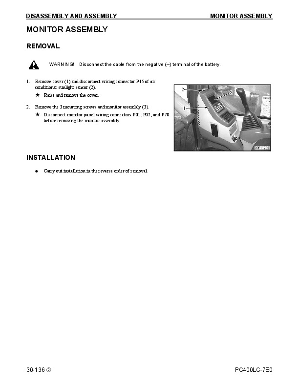
INSTANT DOWNLOAD
Complete service repair manual with Electrical Wiring Diagrams for Komatsu Log Loader/Road Builder Excavator PC390LL-10, with all the technical information to maintain, diagnose, repair, and rebuild like professional mechanics.
Komatsu Log Loader/Road Builder Excavator PC390LL-10 workshop service repair manual includes:
* Numbered table of contents easy to use so that you can find the information you need fast.
* Detailed sub-steps expand on repair procedure information
* Numbered instructions guide you through every repair procedure step by step.
* Troubleshooting and electrical service procedures are combined with detailed wiring diagrams for ease of use.
* Notes, cautions and warnings throughout each chapter pinpoint critical information.
* Bold figure number help you quickly match illustrations with instructions.
* Detailed illustrations, drawings and photos guide you through every procedure.
* Enlarged inset helps you identify and examine parts in detail.
CEAM027101 – Log Loader_Road Builder Excavator PC390LL-10 Operation & Maintenance Manual.pdf
CEBM027501 – Log Loader_Road Builder Excavator PC390LL-10 Shop Manual.pdf
CEBM027502 – Log Loader_Road Builder Excavator PC390LL-10 Shop Manual.pdf
Total Pages: 2,673 pages
File Format: PDF
Language: English
CEAM027101 – Log Loader_Road Builder Excavator PC390LL-10 Operation & Maintenance Manual…2
CEAM027101 PC390LL-10 S/N A50601 and UP…2
INTRODUCTION…4
FORWARD…5
SAFETY INFORMATION…6
Safety Labels…7
INTRODUCTION…8
Intended Use…8
Directions of Machine…8
Structure to Protect the Operator…8
Breaking-In the New Machine…9
Product Information…10
Product Identification Number (Pin)/Machine Serial No. Plate…10
EPA* Regulations, Engine Number Plate…10
Service Meter Location…11
Your Machine Serial Numbers and Distributor…11
Engine Acronyms…11
TABLE OF CONTENTS…12
SAFETY…22
SAFETY LABELS…23
Location of Safety Labels…23
Safety Labels…24
Unique Safety Decals for Log Loader and Road Builder Excavators…32
GENERAL PRECAUTIONS COMMON TO OPERATION AND MAINTENANCE…37
Precautions Before Starting Operation…37
Ensuring Safe Operation…37
Understanding the Machine…37
Preparations for Safe Operation…37
Precautions Regarding Safety-Related Equipment…37
Inspecting Machine…37
Clothing and Personal Protective Items…37
Keep Machine Clean…38
Keep Operator's Compartment Clean…38
Fire Extinguisher and First Aid Kit…38
Safety Equipment…38
If Problems are Found…38
Fire Prevention and Explosion Prevention…39
Action if Fire Occurs…40
Handrails and Steps…41
Mounting and Dismounting…41
No Persons on Attachments…41
Leaving Operator's Seat with Lock…42
Emergency Exit from Operator's Cab…42
Do Not Get Caught in Work Equipment…43
Precautions Related to Protective Structures…43
Falling Objects, Flying Objects and Intruding Objects Prevention…43
Unauthorized Modification…44
Precautions Related to Attachments and Options…44
Precautions Related to Cab Glass…44
Precautions When Running Engine Inside Building…44
Safety at Job Site…45
Working on Loose Ground…45
Distance to High Voltage Cables…45
Ensure Good Visibility…46
Signalman's Signal and Signs…46
Asbestos Dust Hazard Prevention…47
SAFETY MACHINE OPERATION…48
Starting Engine…48
Checks Before Starting Engine…48
Safety Rules for Starting Engine…49
Starting Engine in Cold Weather…49
Starting Engine with Booster Cables…49
Operation…50
Checks Before Operation…50
Safety Rules for Changing Machine Directions…50
Safety Rules for Traveling…51
Traveling on Slopes…52
Operations on Slopes…53
Prohibited Operations…54
Operations on Snow or Frozen Surfaces…56
Parking Machine…56
TRANSPORTATION…57
Loading and Unloading…57
Shipping the Machine…58
TOWING…58
Safety Rules for Towing…58
LIFTING OBJECTS WITH BUCKET…59
Safety Rules for Lifting Objects…59
SAFETY MAINTENANCE INFORMATION…60
Warning Tag…60
Keep Work Place Clean and Tidy…60
Select Suitable Place for Inspection and Maintenance…60
Only Authorized Personnel…60
Appoint Leader When Working with Others…60
Stop Engine Before Carrying Out Maintenance…61
Precautions When Working at High Places…61
Two Workers for Maintenance When Engine is Running…62
Attachments…62
Work on Machine…63
Work Under the Machine…63
Proper Tools…63
Battery Disconnect Switch…64
Removing Battery Terminals…64
Welding…64
Battery…64
Battery Hazard Prevention…64
When Using Hammer…65
Precautions with High Temperature Coolant…65
Precautions with High Temperature Oil…66
Safety Rules for High-Pressure Oil…66
Precaution for High Fuel Pressure…66
Safety Handling High-Pressure Hoses or Piping…66
Precaution for High Voltage…67
Noise…67
Safety First When Using High-Pressure Grease to Adjust Track Tension…67
Do Not Disassemble Recoil Springs…68
Accumulator…68
Handling Gas Spring…68
Precautions When Using…68
Precautions When Discarding…69
Compressed Air…69
Air Conditioner Maintenance…69
Waste Materials…69
Select Window Washer Fluid…69
Personnel…69
Periodic Replacement of Safety Critical Parts…70
OPERATION…72
MACHINE VIEW ILLUSTRATIONS…73
General View of Log Loader Machine…73
General View of Road Builder Machine…74
General View of Cab…76
CONTROLS AND GAUGES…77
Machine Monitor…78
EXPLANATION OF COMPONENTS…79
Machine Monitor…79
Basic Operation of Machine Monitor…80
Warning Display…85
Meter Display…95
Gauges and Meter…102
Monitor Switches Portion…105
Handling Function Switches…115
User Menu Selector Switch…119
User Menu…120
Machine Settings…132
Maintenance Screen Setting…137
Monitor Setting…139
Screen Adjustment…139
Screen Adjustment (Camera)…140
Clock Adjustment…140
Time…142
SWITCHES…147
Starting Switch…148
Fuel Control Dial…148
Cigarette Lighter…148
Swing Lock Switch…149
Lamp Switch…149
Room Lamp Switch…150
Soft Swing Switch…151
Emergency Pump Drive Switch…152
Swing Brake Cancel Switch…152
Seat Heater Switch…153
Engine Shutdown Secondary Switch…154
CONTROL LEVERS AND PEDALS…155
Lock Lever…155
Travel Levers…156
Work Equipment Control Lever…157
EMERGENCY ESCAPE…158
ENGINE HOOD…159
When Opening (Normal Case: Intermediate Lock Position)…159
When Closing (Normal Case: Intermediate Lock Position)…161
CAPS AND COVERS WITH LOCK…163
Open and Close Caps with Lock…163
Opening the Cap…163
Locking the Cap…163
Open and Close Covers with Lock…164
Opening the Cover (Locked Cover)…164
Locking the Cover…164
Lock and Unlock Engine Hood…164
Opening the Hood (Locked Hood)…164
Locking the Hood…164
Lock and Unlock Cab Door…165
Opening the Door (Locked Door)…165
Locking the Door…165
DRINK BOX…166
MAGAZINE BOX…166
CUP HOLDER…166
ASHTRAY…167
AIR CONDITIONER CONTROLS…168
Air Conditioner Control Panel…168
Method of Operation…173
Automatic Operation…173
Stopping Automatic Operation…174
Manual Operation…174
Stop Manual Operation…176
Operation with Cold Air to Face and Warm Air to Feet…176
Defroster Operation…178
Rules for Using Air Conditioner…180
Air Conditioner Maintenance…180
RADIO…181
Control Panel…181
Operation Method…183
Frequency Adjustment…183
Frequency Adjustment (Auto Presetting)…183
Preset Call…183
Preset Memory…183
Sound Adjustment (Balance)…183
Sound Adjustment (Treble)…184
Sound Adjustment (Bass)…184
Time Adjustment…184
Stowing Radio Antenna…184
AUXILIARY ELECTRIC POWER…185
24 V Power Source…185
12 V Power Source…185
FUSE…186
FUSIBLE LINK…188
TOOL BOX…188
GREASE GUN HOLDER…188
BATTERY DISCONNECT SWITCH…189
SYSTEM OPERATING LAMP…190
HANDLING KOMATSU DIESEL PARTICULATE FILTER (KDPF)…191
Operation Procedure of Manual Stationary Regeneration…196
Komatsu Diesel Particulate Filter (KDPF) Regeneration Disable Procedure…199
While Regeneration is Being Performed: Stopping Regeneration…200
Handling Komatsu Closed Crankcase Ventilation (KCCV)…201
HANDLING MACHINES EQUIPPED WITH KOMTRAX…202
Basic Precautions…202
MACHINE OPERATIONS AND CONTROLS…203
Before Starting Engine…203
Walk-Around Checks…203
Checks Before Starting…205
Adjustment…215
Seat Belt Inspection…224
Seat Belt…225
Operations Before Starting Engine…226
STARTING ENGINE…228
Turbo Protect Function…231
AFTER STARTING ENGINE…232
Engine Warm Up…234
Hydraulic System Warm-Up…236
Operation After Completion of Warming-Up Operation…242
STOPPING THE ENGINE…244
MACHINE OPERATION…245
Preparations for Moving the Machine…245
Moving Machine Forward…246
Moving Machine Backward…247
Stopping Machine…248
STEERING THE MACHINE…249
Steering…249
Steering the Machine When Stopped…249
Changing Direction of the Machine…250
Counter-Rotation Turn (Spin Turn)…250
SWINGING…251
WORK EQUIPMENT CONTROLS AND OPERATIONS…252
WORKING MODE…254
Working Mode Switch…254
One-Touch Power Max. Switch…256
PROHIBITED OPERATIONS…257
GENERAL OPERATION INFORMATION…260
Traveling…260
High Speed Travel…260
Permissible Water Depth…261
TRAVELING ON SLOPES…262
ESCAPE FROM MUD…264
Track on One Side Stuck…264
Tracks on Both Sides Stuck…264
RECOMMENDED APPLICATIONS…265
Backhoe Work…265
Shovel Work…265
Ditching Work…265
Loading Work…266
BUCKET REPLACEMENT AND INVERSION…267
Replacement…267
Inversion…269
PARKING MACHINE…271
MACHINE INSPECTION AFTER DAILY WORK…273
LOCKING…273
TRANSPORTATION…273
Transportation Procedure…273
Loading and Unloading with Trailer…274
Loading…275
Securing Machine…278
Stowing Radio Antenna…282
Rear View Mirrors…282
Unloading…285
LIFTING MACHINE…287
Standard Specification Machines…287
COLD WEATHER OPERATION…289
Cold Weather Operation Information…289
Fuel and Lubricants…289
Coolant…289
Battery…290
AFTER DAILY WORK COMPLETION…291
AFTER COLD WEATHER SEASON…291
LONG TERM STORAGE…292
Before Storage…292
During Storage…292
After Storage…293
Starting Machine After Long-Term Storage…293
TROUBLES AND ACTIONS…294
Running Out of Fuel…294
Phenomena that are Not Failures…294
Towing the Machine…295
Lightweight Towing Hole…296
Severe Job Condition…296
Discharged Battery…297
Battery Removal and Installation…297
Battery Charges…298
Starting Engine with Booster Cables…299
OTHER TROUBLE…301
Electrical System…301
Chassis…302
Engine…303
Electronic Control System…305
Point of Contact to Telephone When Error Occurs…305
MAINTENANCE…306
MAINTENANCE INFORMATION…307
OUTLINE OF SERVICE…309
Handling Oil, Fuel, Coolant, and Performing Oil Clinic…309
Oil…309
Fuel…310
Coolant and Water for Dilution…310
Grease…311
Carrying Out KOWA (Komatsu Oil Wear Analysis)…311
Storing Oil and Fuel…312
Filters…312
Electric System Maintenance…312
WEAR PARTS…313
Wear Parts List…313
RECOMMENDED FUEL, COOLANT, AND LUBRICANT…314
Lubrication Chart…314
Fuel, Coolant, and Lubricants to Match the Ambient Temperature…316
KDPF (Komatsu Diesel Particulate Filter)…316
Recommended Brands, Recommended Quality for Products Other than Komatsu Genuine Oil…317
TORQUE SPECIFICATIONS…318
Torque List…318
Torque of Bolts…318
Torque of Hose Nuts…319
Torque of Split Flange Bolts…319
Torque for Flared Nuts…319
Torque for O-Ring Boss Piping Joints…321
Torque for O-Ring Boss Plugs…321
Torque for Hoses (Taper Seal Type and Face Seal Type)…322
SAFETY CRITICAL PARTS…323
Safety Critical Parts List…324
MAINTENANCE SCHEDULE…325
Maintenance Schedule Table…325
MAINTENANCE PROCEDURE…327
Initial 10 Hours Maintenance…327
Initial 250 Hours Maintenance (Only After the First 250 Hours)…327
Initial 500 Hours Maintenance (Only After the First 500 Hours)…327
When Required…328
Check, Clean and Replace Air Cleaner Element…328
Clean Inside of Cooling System…335
Check and Tighten Track Shoe Bolts…341
Check and Adjust Track Tension…342
Replace Bucket Teeth (Vertical Pin Type)…344
Replace Bucket Teeth (Horizontal Pin Type)…347
Replace Bucket Side Cutter, Shroud…349
Adjust Bucket Clearance…350
Check Window Washer Fluid Level, Add Fluid…351
Check and Maintain Air Conditioner…352
Wash Washable Floor…353
Set Machine at Angle…355
Check Gas Spring…356
Bleeding Air From Hydraulic System…357
Check Before Starting…359
Every 50 Hours Maintenance…360
Lubricating Road Builder…360
Lubricating Log Loader…362
Every 250 Hours Maintenance…363
Check Level of Battery Electrolyte…363
Check Air Conditioner Compressor Belt Tension, Adjust…365
Lubricate Swing Circle…366
Check Oil Level in Swing Machinery Case, Add Oil…367
Every 500 Hours Maintenance…368
Lubricating…368
Change Oil in Engine Oil Pan…370
Replace Engine Oil Filter Cartridge…370
Replace Fuel Pre-Filter Cartridge…372
Check Swing Pinion Grease Level, Add Grease…376
Clean and Inspect Radiator Fins, Oil Cooler Fins, Aftercooler Fins, Fuel Cooler Fins, and Condenser Fins…377
Clean Air Conditioner Fresh/Recirc Filters…379
Replace Breather Element in Hydraulic Tank…381
Replace Additional Breather Element in Hydraulic Tank…382
Check Oil Level in Final Drive Case, Add Oil…383
Check Oil Level in Swing Machinery Case, Add Oil…384
Every 1000 Hours Maintenance…385
Replace Hydraulic Oil Filter Element…385
Change Oil in Swing Machinery Case…386
Check Oil Level in Damper Case, Add Oil…387
Replace Fuel Main Filter Cartridge…388
Check All Tightening Points of Engine Exhaust Pipe Clamps…390
Check Fan Belt Tension and Replace Fan Belt…390
Check Nitrogen Gas Charge Pressure in Accumulator (For Breaker)…390
Every 2000 Hours Maintenance…391
Change Oil in Final Drive Case…391
Clean Hydraulic Tank Strainer…392
Check Charge Pressure of Nitrogen Gas in Accumulator (For Control Circuit)…393
Check Alternator…397
Check Engine Valve Clearance, Adjust…397
Replace Komatsu Closed Crankcase Ventilation (KCCV) Filter Element…398
Every 4000 Hours Maintenance…402
Check Water Pump…402
Check Vibration Damper…402
Check Starting Motor…402
Replace Accumulator (For Control Circuit)…403
Check for Missing Fuel Spray Prevention Cap, Hardening of Rubber…404
Check Operating Condition of Compressor…404
Every 4500 Hours Maintenance…405
Clean Komatsu Diesel Particulate Filter (KDPF)…405
Replace Komatsu Closed Crankcase Ventilation (KCCV) Hose…405
Every 5000 Hours Maintenance…406
Change Oil in Hydraulic Tank…406
Every 8000 Hours Maintenance…408
Replace Fuel Spray Prevention Cap…408
Replace High-Pressure Piping Clamp…408
SPECIFICATIONS…410
SPECIFICATIONS…411
Dimensions…412
Working Range…415
Road Builder…415
Log Loader…417
Lifting Capacity…419
OPTIONS, ATTACHMENTS…422
GENERAL PRECAUTIONS FOR SAFETY…423
Precautions When Selecting…423
Read the Operation and Maintenance Manual Thoroughly…423
Precautions When Removing or Installing…423
Precautions When Using…423
BUCKET WITH HOOK…424
Hook Condition…424
Safety Rules for Lifting Operations…424
Straight Travel (Option)…425
TRACK SHOES SELECTION…427
BUCKET TEETH SELECTION…428
Selection Guide for Horizontal or Vertical Pin Type Tooth…428
CEBM027501 – Log Loader_Road Builder Excavator PC390LL-10 Shop Manual…430
CEBM027501 PC390LL-10 S/N A50601-…430
CONTENTS…432
00 – FOREWORD…433
SAFETY…433
Safety Notice…433
Important Safety Notice…433
General Precautions…433
Preparations For Work…434
Precautions During Work…434
GENERAL…437
HOW TO READ THE SHOP MANUAL…439
Volumes…439
Distribution and Updating…439
Filing Method…439
Revised Edition Mark…439
Revisions…439
Symbols…439
HOISTING INSTRUCTIONS…440
Hoisting…440
Making Signs…440
Precautions…440
Precautions for Sling Work…440
Precautions for Using Mobile Crane…441
Precautions for Using Overhead Hoist Crane…441
Selecting Wire Ropes…442
HANDLING ELECTRIC EQUIPMENT AND HYDRAULIC COMPONENTS…443
Points to Remember When Handling Electric Equipment…443
Points to Remember When Handling Hydraulic Equipment…455
PUSH PULL COUPLER…457
Type 1…457
Disconnection…457
Connection…457
Type 2…458
Disconnection…458
Connection…458
Type 3…459
Disconnection…459
Connection…459
EXPLANATION OF MAINTENANCE STANDARD TERMS…460
HANDLING OF FUEL SYSTEM DEVICES…461
HANDLING OF INTAKE SYSTEM PARTS…462
STANDARD TIGHTENING TORQUE…463
Bolts And Nuts…463
Tightening Torque Of Hose Nuts…464
Tightening Torque Of Split Flange Bolts…464
Tightening Torque For Flared Nuts…464
Tightening Torques for Split Flanged Bolts…465
Tightening Torques For O-ring Boss Piping Joints…465
Table Of Tightening Torques For O-ring Boss Plugs…465
Tightening Torque For Hoses (Taper Seal Type And Face Seal Type)…466
Tightening Torque For Face Seal Joints…466
For 102, 107, and 114 Engine Series (Bolts and Nuts)…466
For 102, 107, and 114 Engine Series (Eye Joints)…467
For 102, 107, and 114 Engine Series (Taper Screws)…467
ELECTRIC WIRE CODE…468
Classification By Thickness…468
Classification By Color And Code…468
How To Read Electric Wire Code…469
PRECAUTIONS FOR OPERATIONS…472
Precautions When Carrying Out Removal Work…472
Precautions When Carrying Out Installation Work…473
Precautions When Completing the Operation…474
CONVERSION TABLES…475
Method Of Using The Conversion Table…475
COATING MATERIALS…481
LIST OF ABBREVIATIONS…483
List of Abbreviations Used in the Shop Manual…483
List of Abbreviations Used in the Circuit Diagrams…487
01 – GENERAL…489
SPECIFICATIONS…490
Dimension Drawings…490
Road Builder…490
Log Loader…490
Dimensions…491
Working Ranges…492
Road Builder…492
Log Loader…493
Engine…494
Undercarriage…494
Hydraulic System…495
Road Builder…495
Log Loader…496
WEIGHT TABLE…497
FUEL, COOLANT AND LUBRICANTS…499
Lubrication Chart…501
10 – STRUCTURE AND FUNCTION…503
ENGINE AND COOLING SYSTEM…506
Engine Related Parts…506
Cooling System…508
POWERTRAIN SYSTEM…510
Powertrain…510
Swing Circle…512
Final Drive…513
TRACK FRAME • RECOIL SPRING…514
HYDRAULIC SYSTEM…516
Hydraulic Component Layout…516
Valve Control…518
Hydraulic Tank…520
Oil Filler Cap…521
CLSS…522
Structure of CLSS…522
Basic principle…523
Main Pump…526
Operation…530
LS Valve…532
PC Valve…538
LS(PC)-EPC Valve…545
Control Valve…548
Functions and Operation by Valve…560
Hydraulic Circuit Diagram and Name of Valves…560
Unload Valve…562
Introduction of LS Pressure…563
LS By-Pass Plug…564
Pressure Compensation Valve…565
Shuttle Valve In Pressure Compensation Valve…568
Boom Regeneration Circuit…570
Arm Regeneration Circuit…572
Merge-Divider Valve…574
LS Selector Valve…577
Self-Pressure Reducing Valve…578
Travel Junction Valve…581
Travel PPC Shuttle Valve…584
Boom Hydraulic Drift Prevention Valve…586
Arm Hydraulic Drift Prevention Valve (Road Builder)…589
Arm Drift Prevention Valve (Log Loader)…592
Operation…593
Suction Safety Valve for Drift Prevention Valve…595
Arm Quick Return Valve…596
Variable Back Pressure Valve…598
Main Relief Valve…600
Suction 2-Stage Safety Valve…601
Swing Motor…603
Swing Holding Brake…605
Relief Valve…607
Swing 2-Stage Relief Valve…609
Swing Motor Reverse Prevention Valve…610
Travel Motor – Type KMV200ADT-2…613
Operation of Travel Motor…616
Parking Brake…618
Brake Valve…620
Safety Valve…622
PPC Valve…626
Work Equipment and Swing PPC Valve…626
Travel PPC Valve…631
1st-Line Attachment PPC Valve (with EPC Valve) (If Equipped)…636
EPC Valve (If Equipped)…638
2nd-Line Attachment PPC Valve (If Equipped)…641
Solenoid Valve…643
Attachment Solenoid Valve…645
Center Swivel Joint…647
Accumulator…648
PPC Accumulator…648
WORK EQUIPMENT…649
Work Equipment – Road Builder…649
Work Equipment – Log Loader…650
Work Equipment Shim…651
Bucket Play Adjustment Shim…651
ELECTRICAL SYSTEM…653
Electrical Control System…653
Machine Control System Diagram…653
Engine Control Function…655
Engine and Pump Combined Control Function…657
Pump and Valve Control Function…663
One-Touch Power Maximizing Function…665
Machine Push-Up Function…667
Auto-Deceleration Function…669
Engine Automatic Warm-Up Function…671
Overheat Prevention Function…673
Turbocharger Protection Function…674
Swing Control Function…675
Swing Control Function (with Soft Swing Option)…676
Quick Warm-Up Function…678
Swing 2-Stage Relief Function…678
Travel Control Function…679
PPC Lock Function…681
Attachment Flow Control Function…682
System Component Part…683
Engine Controller…683
Pump Controller…687
Fuel Control Dial…690
Resister for PC-EPC valve…691
CAN Terminating Resistor…692
Engine Oil Pressure Switch…693
PPC Oil Pressure Switch…694
MACHINE MONITOR SYSTEM…695
Machine Monitor…697
Input and Output Signals…698
Display…700
Gauges…702
Caution Monitor…704
Pilot Monitor…707
Switches…710
Guidance ICON and Function Switch…712
Operator Mode Function…715
Service Mode Function…717
KOMTRAX SYSTEM…718
KOMTRAX terminal…719
Input and Output Signals…720
SENSORS…722
Ambient Pressure Sensor…722
Charge (Boost) Pressure and Temperature Sensor…723
Coolant Temperature Sensor…724
Ne (Crankshaft) Speed Sensor…724
Bkup (Camshaft) Speed Sensor…725
Common Rail Pressure Sensor…725
Exhaust Manifold Pressure Sensor…726
EGR Orifice Temperature Sensor…726
EGR Valve Lift Sensor…727
Turbo Speed Sensor…728
KVGT Position Sensor…729
Mass Air Flow and Temperature Sensor…730
KDPF Differential Pressure and Outlet Pressure Sensor…730
KDOC Inlet Temperature Sensor…731
KDOC Outlet Temperature Sensor…731
KDPF Outlet Temperature Sensor…732
Crankcase Pressure Sensor…732
Engine Oil Level Sensor…733
Fuel Level Sensor…734
Coolant Level Sensor…735
Hydraulic Oil Temperature Sensor…735
Front Pump Oil Pressure Sensor…736
Rear Pump Oil Pressure Sensor…737
PPC Oil Pressure Sensor…738
Air Cleaner Clogging Sensor…739
Front Pump Swash Plate Sensor…740
Rear Pump Swash Plate Sensor…742
Water-In-Fuel Sensor…744
20- STANDARD VALUE TABLES…745
STANDARD SERVICE VALUE TABLES…746
Standard Value Table for Engine Related Parts…746
Standard Value Table for Chassis Related Parts…748
Engine Speed…748
Travel of Control Valve Spool…748
Travel of Control Lever…749
Operating Effort of Control Lever and Pedal…749
Hydraulic Pressure…750
Swing…751
Travel…752
Work Equipment…753
Performance in Combined Operation…754
Pump Swash Plate Sensor…755
Main Pump…755
Posture of Machine for Measuring Performance and Measurement Procedure…757
Control Valve: Spool Stroke…757
Swing 1: Overrun When Stopping Swing, Time Taken to Start Swing, Time Taken to Swing…757
Swing 2: Hydraulic Drift of Swing…757
Travel 1: Travel Speed, Idle Running (Without Load)…758
Travel 2: Travel Speed (Actual Run), Travel Deviation…758
Travel 3: Travel Deviation…759
Travel 4: Hydraulic Drift of Travel…759
Work Equipment 1: Hydraulic Drift of Work Equipment…760
Work Equipment 2: Boom Speed…760
Work Equipment 3: Arm Speed…760
Work Equipment 4: Bucket Speed/Heel Speed…761
Work Equipment 5: Boom Time Lag…761
Work Equipment 6: Arm Time Lag…762
Work Equipment 7: Bucket Time Lag…762
90- DIAGRAMS AND SCHEMATICS…763
HYDRAULIC CIRCUIT DIAGRAM…765
Symbols in Hydraulic Circuit Diagram…765
Hydraulic Circuit Diagram (1/2)…768
Hydraulic Circuit Diagram (2/2)…769
ELECTRICAL SYSTEM…770
Symbols in Electrical Circuit Diagrams…770
Air Conditioner Electrical Circuit Diagram…773
Electrical Circuit Diagram – Log Loader Unique…774
Electrical Circuit Diagram (1/6)…775
Electrical Circuit Diagram (2/6)…776
Electrical Circuit Diagram (3/6)…777
Electrical Circuit Diagram (4/6)…778
Electrical Circuit Diagram (5/6)…779
Electrical Circuit Diagram (6/6)…780
Cab Diagram…781
CEBM027502 – Log Loader_Road Builder Excavator PC390LL-10 Shop Manual…782
CEBM027502 PC390LL-10…782
CONTENTS…783
00 – FORWARD…784
SAFETY…784
Safety Notice…784
Important Safety Notice…784
General Precautions…784
Preparations For Work…785
Precautions During Work…785
GENERAL…788
HOW TO READ THE SHOP MANUAL…790
Volumes…790
Distribution and Updating…790
Filing Method…790
Symbols…790
HOISTING INSTRUCTIONS…791
Hoisting…791
Making Signs…791
Precautions…791
Precautions for Sling Work…791
Precautions for Using Mobile Crane…792
Precautions for Using Overhead Hoist Crane…792
Selecting Wire Ropes…793
HANDLING ELECTRIC EQUIPMENT AND HYDRAULIC COMPONENTS…794
Points to Remember When Handling Electric Equipment…794
Points to Remember When Handling Hydraulic Equipment…806
PUSH PULL COUPLER…808
Type 1…808
Disconnection…808
Connection…808
Type 2…809
Disconnection…809
Connection…809
Type 3…810
Disconnection…810
Connection…810
EXPLANATION OF MAINTENANCE STANDARD TERMS…811
HANDLING OF FUEL SYSTEM DEVICES…812
HANDLING OF INTAKE SYSTEM PARTS…813
STANDARD TIGHTENING TORQUE…814
Bolts And Nuts…814
Tightening Torque Of Hose Nuts…815
Tightening Torque Of Split Flange Bolts…815
Tightening Torque For Flared Nuts…815
Tightening Torques for Split Flanged Bolts…816
Tightening Torques For O-ring Boss Piping Joints…816
Table Of Tightening Torques For O-ring Boss Plugs…816
Tightening Torque For Hoses (Taper Seal Type And Face Seal Type)…817
Tightening Torque For Face Seal Joints…817
For 102, 107, and 114 Engine Series (Bolts and Nuts)…817
For 102, 107, and 114 Engine Series (Eye Joints)…818
For 102, 107, and 114 Engine Series (Taper Screws)…818
ELECTRIC WIRE CODE…819
Classification By Thickness…819
Classification By Color And Code…819
How To Read Electric Wire Code…820
PRECAUTIONS FOR OPERATIONS…823
Precautions When Carrying Out Removal Work…823
Precautions When Carrying Out Installation Work…824
Precautions When Completing the Operation…825
CONVERSION TABLES…826
Method Of Using The Conversion Table…826
COATING MATERIALS…832
LIST OF ABBREVIATIONS…834
List of Abbreviations Used in the Shop Manual…834
List of Abbreviations Used in the Circuit Diagrams…838
01 – GENERAL…840
SPECIFICATIONS…841
Dimension Drawings…841
Road Builder…841
Log Loader…841
Dimensions…842
Working Ranges…844
Road Builder…844
Log Loader…845
Engine…846
Undercarriage…846
Hydraulic System…847
Road Builder…847
Log Loader…848
WEIGHT TABLE…849
FUEL, COOLANT AND LUBRICANTS…851
Lubrication Chart…853
10 – STRUCTURE AND FUNCTION…854
ENGINE AND COOLING SYSTEM…857
Engine Related Parts…857
Cooling System…859
POWERTRAIN SYSTEM…861
Powertrain…861
Swing Circle…863
Final Drive…864
TRACK FRAME • RECOIL SPRING…865
MEMORANDUM…866
HYDRAULIC SYSTEM…867
Hydraulic Component Layout…867
Valve Control…869
Hydraulic Tank…871
Oil Filler Cap…872
CLSS…873
Structure of CLSS…873
Basic principle…874
Main Pump…877
Operation…881
LS Valve…883
PC Valve…889
LS(PC)-EPC Valve…896
Control Valve…899
Functions and Operation by Valve…911
Hydraulic Circuit Diagram and Name of Valves…911
Unload Valve…913
Introduction of LS Pressure…914
LS By-Pass Plug…915
Pressure Compensation Valve…916
Shuttle Valve In Pressure Compensation Valve…919
Boom Regeneration Circuit…921
Arm Regeneration Circuit…923
Merge-Divider Valve…925
LS Selector Valve…928
Self-Pressure Reducing Valve…929
Travel Junction Valve…932
Travel PPC Shuttle Valve…935
Boom Hydraulic Drift Prevention Valve…937
Arm Hydraulic Drift Prevention Valve (Road Builder)…940
Arm Drift Prevention Valve (Log Loader)…943
Operation…944
Suction Safety Valve for Drift Prevention Valve…946
Arm Quick Return Valve…947
Variable Back Pressure Valve…949
Main Relief Valve…951
Suction 2-Stage Safety Valve…952
Swing Motor…954
Swing Holding Brake…956
Relief Valve…958
Swing 2-Stage Relief Valve…960
Swing Motor Reverse Prevention Valve…961
Travel Motor – Type KMV200ADT-2…964
Operation of Travel Motor…967
Parking Brake…969
Brake Valve…971
Safety Valve…973
1. When pressure in chamber (MB) has become high (when rotating clockwise)…973
2. When pressure in chamber (MA) has become high (when rotating counterclockwise)…973
1. When starting travel (high-pressure setting)…974
2. When travel is stopped (low-pressure setting)…975
MEMORANDUM…976
PPC Valve…977
Work Equipment and Swing PPC Valve…977
Travel PPC Valve…982
MEMORANDUM…986
1st-Line Attachment PPC Valve (with EPC Valve) (If Equipped)…987
EPC Valve (If Equipped)…989
2nd-Line Attachment PPC Valve (If Equipped)…992
Solenoid Valve…994
Attachment Solenoid Valve…996
Center Swivel Joint…998
Accumulator…999
PPC Accumulator…999
WORK EQUIPMENT…1000
Work Equipment – Road Builder…1000
Work Equipment – Log Loader…1001
Work Equipment Shim…1002
Bucket Play Adjustment Shim…1002
ELECTRICAL SYSTEM…1004
Electrical Control System…1004
Machine Control System Diagram…1004
Engine Control Function…1006
Engine and Pump Combined Control Function…1008
Pump and Valve Control Function…1014
One-Touch Power Maximizing Function…1016
Machine Push-Up Function…1018
Auto-Deceleration Function…1020
Engine Automatic Warm-Up Function…1022
Overheat Prevention Function…1024
Turbocharger Protection Function…1025
Swing Control Function…1026
Swing Control Function (with Soft Swing Option)…1027
1. Swing Lock and Swing Holding Brake Functions with Soft Swing…1028
2. Operation of Swing Holding Brake Release Switch…1028
Quick Warm-Up Function…1029
Swing 2-Stage Relief Function…1029
Travel Control Function…1030
PPC Lock Function…1032
Attachment Flow Control Function…1033
System Component Part…1034
Engine Controller…1034
Pump Controller…1038
Fuel Control Dial…1041
Resister for PC-EPC valve…1042
CAN Terminating Resistor…1043
Engine Oil Pressure Switch…1044
PPC Oil Pressure Switch…1045
MACHINE MONITOR SYSTEM…1046
Machine Monitor…1048
Input and Output Signals…1049
Display…1051
Gauges…1053
Caution Monitor…1055
Pilot Monitor…1058
MEMORANDUM…1060
Switches…1061
Guidance ICON and Function Switch…1063
Operator Mode Function…1066
Service Mode Function…1068
KOMTRAX SYSTEM…1069
KOMTRAX terminal…1070
Input and Output Signals…1071
SENSORS…1073
Ambient Pressure Sensor…1073
Charge (Boost) Pressure and Temperature Sensor…1074
Coolant Temperature Sensor…1075
Ne (Crankshaft) Speed Sensor…1075
Bkup (Camshaft) Speed Sensor…1076
Common Rail Pressure Sensor…1076
Exhaust Manifold Pressure Sensor…1077
EGR Orifice Temperature Sensor…1077
EGR Valve Lift Sensor…1078
Turbo Speed Sensor…1079
KVGT Position Sensor…1080
Mass Air Flow and Temperature Sensor…1081
KDPF Differential Pressure and Outlet Pressure Sensor…1081
KDOC Inlet Temperature Sensor…1082
KDOC Outlet Temperature Sensor…1082
KDPF Outlet Temperature Sensor…1083
Crankcase Pressure Sensor…1083
Engine Oil Level Sensor…1084
Fuel Level Sensor…1085
Coolant Level Sensor…1086
Hydraulic Oil Temperature Sensor…1086
Front Pump Oil Pressure Sensor…1087
Rear Pump Oil Pressure Sensor…1088
PPC Oil Pressure Sensor…1089
Air Cleaner Clogging Sensor…1090
Front Pump Swash Plate Sensor…1091
Rear Pump Swash Plate Sensor…1093
Water-In-Fuel Sensor…1095
20 – STANDARD VALUE TABLES…1096
STANDARD SERVICE VALUE TABLES…1097
Standard Value Table for Engine Related Parts…1097
Standard Value Table for Chassis Related Parts…1099
Engine Speed…1099
Travel of Control Valve Spool…1099
Travel of Control Lever…1100
Operating Effort of Control Lever and Pedal…1100
Hydraulic Pressure…1101
Swing…1102
Travel…1103
Work Equipment…1104
Performance in Combined Operation…1105
Pump Swash Plate Sensor…1106
Main Pump…1106
Posture of Machine for Measuring Performance and Measurement Procedure…1108
Control Valve: Spool Stroke…1108
Swing 1: Overrun When Stopping Swing, Time Taken to Start Swing, Time Taken to Swing…1108
Swing 2: Hydraulic Drift of Swing…1108
Travel 1: Travel Speed, Idle Running (Without Load)…1109
Travel 2: Travel Speed (Actual Run), Travel Deviation…1109
Travel 3: Travel Deviation…1110
Travel 4: Hydraulic Drift of Travel…1110
Work Equipment 1: Hydraulic Drift of Work Equipment…1111
Work Equipment 2: Boom Speed…1111
Work Equipment 3: Arm Speed…1111
Work Equipment 4: Bucket Speed/Heel Speed…1112
Work Equipment 5: Boom Time Lag…1112
Work Equipment 6: Arm Time Lag…1113
Work Equipment 7: Bucket Time Lag…1113
30 – TESTING AND ADJUSTING…1114
GENERAL INFORMATION…1119
Tools for Testing, Adjusting, and Troubleshooting…1119
Sketch of Tools for Testing and Adjusting…1126
MEMORANDUM…1128
ENGINE AND COOLING SYSTEM…1129
Checking Engine Speed…1129
1. Preparation work…1129
2. Testing low idle speed…1129
A. Start the engine and set the fuel control dial to the low idle (MIN) position…1129
B. Set all the control levers and pedals for work equipment, swing, and travel to the neutral position and test the engine speed…1129
3. Testing high idle speed…1129
A. Start the engine and set the fuel control dial to the full speed (MAX) position…1129
B. Set the working mode in the Power Mode (P) and set the auto-deceleration to OFF…1129
C. Set the swing lock switch to ON position…1129
D. Set all control the levers and pedals for work equipment, swing, and travel to the neutral position and test the engine speed…1129
4. Testing 2-pump relief speed…1129
A. Start the engine and operate the arm cylinder to "arm IN" stroke end…1129
B. Set the swing lock switch to OFF position…1129
C. Set the fuel control dial to the full speed (MAX) position and set the working mode to the Power mode (P)…1129
D. Operate the left work equipment control lever to relieve the arm circuit at the IN stroke end and test the engine speed…1129
5. Testing speed (around rated speed) at 2-pump relief + one-touch power maximizing function…1129
A. Start the engine and operate the arm cylinder to "arm IN" stroke end…1129
B. Set the fuel control dial to the full speed (MAX) position and set the working mode to the Power mode (P)…1129
C. While operating the left work equipment control lever to relieve the arm circuit at "arm IN" stroke end and pressing the one-touch power maximizing switch, test the engine speed…1129
6. Testing auto-deceleration speed…1130
A. Start the engine, set the fuel control dial to full speed position (MAX), and turn the auto deceleration function ON…1130
B. Set all the control levers and pedals for work equipment, swing, and travel to the neutral position and measure the engine speed when the auto-deceleration operates…1130
Measuring Boost Pressure…1131
1. Open the engine hood and remove boost pressure pickup plug (1) from the intake air connector…1131
2. Install nipple [1] of boost gauge kit A and connect them to gauge [2]…1132
3. Run the engine at middle or higher speed and bleed oil from the hose…1132
4. Set the working mode to the Power mode (P) and turn the swing lock switch ON…1132
5. Measure the boost pressure when the hydraulic relief is made by arm IN operation + one-touch power max. with engine at full speed…1132
6. After finishing measurement, remove the measuring tools and return the removed parts to their original position…1132
1. Open the engine hood and fix stay (1) at the lock position (2)…1132
2. Loosen bolt (4) fixing lock plate (3), lower lock plate (3) and release the lock…1133
3. Pull stay (1) to your side, hold handgrip (4) and push the engine hood backward…1133
4. After pushing the engine hood fully backward, fix stay (1) securely at lock position(5)…1133
MEMORANDUM…1134
Measuring Exhaust Gas Color…1135
1. Open the engine hood and remove plug (1)…1135
2. Testing by using handy smoke checker B1…1135
A. Fit a sheet of filter paper to smoke checker B1…1135
B. Insert the exhaust gas intake pipe in port (3) for the removed plug…1136
C. Start the engine and, while the arm IN circuit is relieved and engine is run at full speed, absorb the exhaust gas to the filtering paper operating the handle of smoke checker B1…1136
D. Remove the filter paper and compare it with the attached scale to make a judgment…1136
E. After finishing measurement, remove the measuring tools and return the removed parts to their original position…1136
3. Testing by using smoke meter B2…1136
A. Connect the probe hose, receptacle of the accelerator switch and air hose to smoke meter B2…1136
B. Connect the power cable to the AC 100 V receptacle…1136
C. Insert probe [1] of the smoke meter B2 into port (3) of the removed plug (1)…1136
D. Loosen the cap nut of the suction pump and set a filter paper there…1136
E. Turn on the power switch of smoke meter B2…1136
F. Start the engine and, while the arm IN circuit is relieved, depress the accelerator pedal of smoke meter B2 to absorb the exhaust gas to the filtering paper…1136
G. Place the filter paper contaminated with exhaust gas on new filter papers (more than 10 sheets) in the filter paper holder and read the indicated value…1136
H. After finishing measurement, remove the measuring tools and return the removed parts to their original position…1136
Measuring and Adjusting Valve Clearance…1137
Testing…1137
1. Open the engine hood and remove step (1) and support (2)…1137
2. Remove debris guarding as required to access areas defined in the following instructions…1137
3. Remove EGR orifice temperature sensor (3) to protect it from damaging…1137
4. Remove brackets (5) (three places) fastened together to the head cover…1138
5. Disconnect hoses (6) and (7), and connectors (8) and (9)…1138
6. In order to secure the space necessary to remove the head cover, remove bracket (9) (four bolts) and bracket (10) (one bolt) and move wiring harness (11) and connector box (12) from the current positions…1138
7. After removing hose (13), remove breather box (14) (two bolts)…1138
8. In order to secure the space necessary to remove the head cover, remove clamps (16) (two places) fixing tube (15) and move tube (15) from the current position…1139
9. Remove head cover mounting bolts (eight bolts)…1139
10. Tilt and pass the head cover through bellows pipe (17) to remove…1139
11. Remove cap (18) of the front gear cover…1139
12. Set the No. 1 cylinder to the compression top dead center…1139
A. Remove cap (19) of the flywheel housing, then insert gear C1 and rotate the crankshaft in the normal direction…1139
B. After aligning TDC stamp line (a) of the front gear cover with stamp line (b) of the supply pump gear, set No.1 piston to the compression top dead center…1139
13. While the No. 1 cylinder is at the compression top dead center, check the valve clearances marked with in the following figure…1140
14. Then, rotate the crankshaft one turn in the normal direction and check the valve clearance of the remaining valves marked …1140
15. The valve clearance is normal if it is within the following standard value range…1140
16. After finishing test, remove the testing tools and restore the machine…1140
Adjustment…1141
1. While fixing adjustment screw (11), loosen lock nut (10)…1141
2. Insert feeler gauge C2 in the clearance between rocker arm (8) and crosshead (9) and adjust the valve clearance with adjustment screw (11)…1141
3. While fixing adjustment screw (11), tighten lock nut (10)…1141
4. After finishing test, remove the testing tools and restore the machine…1141
MEMORANDUM…1142
Measuring Compression Pressure…1143
1. Remove debris guarding as required to access areas defined in the following instructions…1143
2. Remove the cylinder head cover and set the piston of the tested cylinder to the compression top dead center. For detail, see “Measuring and Adjusting Valve Clearance” on page 30-24…1143
3. Remove brackets (1)…1143
4. After removing fuel spray prevention cap (2), remove the sleeve nut and disconnect high-pressure pipe (3)…1144
5. Loosen injector terminal nut (4) to remove the terminal from injector (9)…1144
6. Remove the mounting bolts of rocker arm assembly (5) on the exhaust side, then remove rocker arm assembly (5)…1144
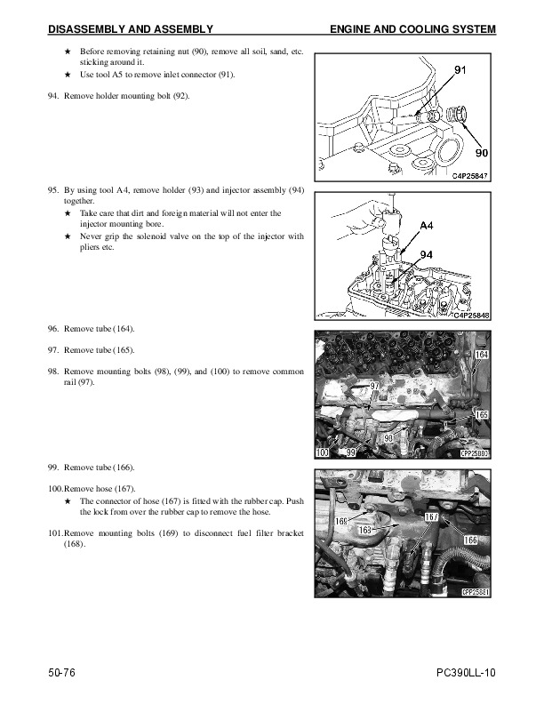
7. Remove retaining nut (6) and remove inlet connector (7)…1144
8. Remove holder (8)…1144
9. Remove injector (9)…1144
10. Install gasket D4 to the tip of adapter D3 and insert them into the injector mounting portion…1145
11. Fix adapter D3 with mounting holders (8) for the injector…1145
12. Install rocker arm assembly (5)…1145
13. Adjust the valve clearances…1145
14. Connect hoses (10) and (11), connectors (12) and (13), and sensor (14)…1145
15. Connect gauge assembly D1 to adapter D3…1146
16. Select the "no injection cranking mode" by operating the machine monitor…1146
17. Rotate the crankshaft by the starting motor and measure the compression pressure…1146
18. After finishing the test, remove the testing tools and restore the machine…1146
A. Install the injector to the cylinder head while facing its fuel inlet hole to the air intake manifold…1146
B. Tighten holder mounting bolt (19) by three to four threads…1146
C. Set inlet connector (7)…1146
D. Check inlet connector (7) for the following items. If anything wrong is found, replace it…1146
i. When burrs or wear is found in the inlet connector top-end (a) and rear-end (b) portions…1146
ii. When foreign matters are found in the edge filter at rear- end (c) of the inlet connector…1146
iii. Cracks or deterioration are recognizable on the O-ring of the inlet connector upper (d) portion…1146
iv. There is a worn part or an uneven seat contact mark on sealing face (e) at the front end of the inlet connector…1147
E. Apply engine oil to the O-ring of inlet connector (7) and the head side…1147
F. Fasten inlet connector (7) temporarily with retaining nut (6)…1147
G. Tighten mounting bolts (19) for holder (8) alternately…1147
H. Tighten retaining nut (6) of inlet connector (7)…1147
I. Tighten the sleeve nut for high-pressure pipe (3) in the order of cylinder head side and common rail (10) side…1147
J. Install fuel spray prevention cap (1)…1147
K. Install rocker arm assembly (5)…1148
L. Adjust the valve clearances…1148
M. Tighten injector terminal nut (4)…1148
N. Install the cylinder head cover…1148
1. The ones which have visually recognizable longitudinal slits (b) or spots (c) in the area within 2 mm from the tip (a)…1148
2. The ones on which fingernail is caught by a level difference that develops on the taper seal end within 2 mm from the tip (d) due to fatigue…1148
1. Fasten inlet connector (1) by use of retaining nut (2) with the specified torque…1149
2. When installing common rail (3), loosen three mounting bolts (4) to (6) once, then temporarily finger tighten them…1149
3. Install high-pressure pipe assembly (7) between the supply pump and common rail, then tighten the sleeve nuts on the supply pump side and common rail side to the specified torque…1149
4. Install injection pipes (8) to (13) between the common rail and each cylinder inlet connector, then tighten the sleeve nuts on the inlet connector side and common rail side to the specified torque…1149
5. Tighten three common rail mounting bolts (4) to (6) to the specified torque…1149
6. Tighten the brackets of the sandwich clamps, that fix the high-pressure pipe and injection pipe, to the specified torque…1149
7. Tighten sandwich clamp (19) to the specified torque…1150
1. Fasten inlet connector (1) by tightening retaining nut (2) to the specified torque…1150
2. When installing common rail (3), loosen three mounting bolts (4) to (6) once, then temporarily finger tighten them…1150
3. Install injection pipes (7) to (12) between the common rail and each cylinder inlet connector, then tighten the sleeve nuts on the inlet connector side and common rail side to the specified torque…1150
4. Tighten three common rail mounting bolts (4) to (6) to the specified torque…1150
5. Tighten the bolts for the brackets of the sandwich clamps, that fix the high-pressure pipe and injection pipe, to the specified torque…1151
6. Fasten sandwich clamp (19) by tightening the bolt to the specified torque…1151
1. Install high-pressure pipe assembly (7) between the supply pump and common rail, then tighten the sleeve nuts on the supply pump side and common rail side to the specified torque…1151
2. Tighten sleeve nuts for the injection pipes (8) to (13) between the common rail and each cylinder inlet connector and sleeve nuts on the common rail side to the specified torque…1151
3. Loosen all the sandwich clamps for the injection pipe…1152
4. Tighten the mounting bolts for brackets (14) to (18) for the sandwich clamp to the specified torque…1152
5. Fasten sandwich clamp (19) by tightening the bolt to the specified torque…1152
Measuring Blow-By Pressure…1153
1. Open the engine hood and remove crank case pressure sensor (1)…1153
2. Disconnect hose (3) on gas outlet side of the KCCV, then plug hose (3) and KCCV tube by using plugs E2…1153
3. After disconnecting hose (4) on the inlet side of KCCV, plug the tube of KCCV to which the hose is connected by using plug E2, install tool and adapter [1] of blow-by checker E1 to hose (4), and then connect gauge [2]…1154
4. After installing crank case pressure sensor (1), start the engine and set the work equipment mode to power mode (P), and turn the swing lock switch to the ON position…1154
5. While running the engine at high idle, relieve the arm IN circuit and measure the blow by pressure…1154
6. After finishing measurement, remove the measuring tools and return the removed parts to their original position…1154
Measuring Engine Oil Pressure…1155
1. Remove oil pressure pickup plug (2) at the bottom of engine controller wiring harness (1)…1156
2. After installing adapter F2, install nipple [1] in the hydraulic tester F4 and connect sensor adapter assembly F1…1156
3. Connect service oil pressure connector (CNP49) (11) and sensor adapter assembly F1…1156
4. Start the engine and set the machine monitor to "Monitoring/Pre- defined" or "Monitoring" screen…1156
5. Measure the oil pressures when the engine runs at the rated output speed and low idle…1157
6. After finishing test remove the testing tools and return the removed parts…1157
1. Remove oil pressure pickup plug (2) at the bottom of engine controller wiring harness (1)…1157
2. After Installing adapter F2, install nipple [1] and hose [2] in hydraulic tester F4, then connect them to oil pressure gauge F5…1157
3. Start the engine and turn the auto-decelerator OFF…1157
4. Measure the oil pressures when the engine runs at the rated output speed and low idle…1157
5. After finishing test remove the testing tools and return the removed parts…1157
MEMORANDUM…1158
Measuring EGR Valve and KVGT Oil Pressure…1159
1. Remove debris guarding as required to access areas defined in the following instructions…1159
2. Open the engine hood and remove step (1)…1159
3. Disconnect hoses (2) and (3)…1159
4. Install adapter G1 and G2, the install nipple [1] and hose [2] of hydraulic tester G3 and connect them to gauge [4]…1160
5. Start the engine and measure the oil pressure at low idle…1160
6. After completing measurement, remove the measuring tools and return the machine to the original condition…1160
Measuring Fuel Pressure…1161
Testing Low-Pressure Circuit (Main Fuel Filter Inlet Side)…1163
1. Open the side cover on the right side of the machine and remove fuel pressure pickup port plug (1) on the main fuel filter inlet side…1163
2. Install adapter H3, install nipple [1] and hose [2] of hydraulic tester H1 and connect them to oil pressure gauge H4…1163
3. Start the engine and measure the pressure in the low-pressure circuit with the engine at high idle…1163
4. After completing measurement, remove the measuring tools and return the machine to the original condition…1163
Testing Low-Pressure Circuit (Pressure Difference)…1164
1. Remove fuel pressure pickup plug (1) at the main fuel filter inlet side and fuel pressure pickup plug (2) on the outlet side…1164
2. Install adapter H3 to each of the inspection holes on the inlet and outlet sides, and then install nipple [1] and hose [2] in hydraulic tester H1, and connect them to oil pressure gauge H4…1164
3. Start the engine and measure the pressure on the inlet and outlet sides of the low-pressure circuit with the engine at high idle…1164
4. Calculate the pressure difference in the low pressure circuit…1164
5. After completing measurement, remove the measuring tools and return the machine to the original condition…1164
Testing Return Circuit…1165
1. Remove pipe (1) between the air cleaner and KVGT…1165
2. Remove brackets (2)…1165
3. Remove joint bolt (3) from the fuel return hose of the supply pump…1165
4. In place of joint bolt (3), install screw H5 and nipple [1] and hose [2] in hydraulic tester H1, and then connect them to oil pressure gauge [3]…1165
5. After installing pipe (1) between the air cleaner and KVGT, start the engine and measure the pressure in the return circuit with the engine at high idle…1166
6. After finishing test, remove the testing tools and restore the machine…1166
Testing the Negative Pressure Circuit (At Fuel Supply Connector)…1167
1. Remove fuel pressure pickup plug (1) of the fuel supply connector…1167
2. Connect adapter H3 and fuel vacuum gauge H6…1167
3. Start the engine and measure the pressure in the negative pressure circuit with the engine at high idle…1167
4. After finishing test, remove the testing tools and restore the machine…1167
Testing the Negative Pressure Circuit (At Supply Pump)…1168
1. Disconnect fuel tube(1) from supply pump (2)…1168
2. Remove fitting (3) mounted to supply pump (2)…1168
3. Install hose assembly [1] of adapter kit H7 to fitting H8, and install them to supply pump (2)…1168
4. Reconnect fuel tube (1)…1168
5. Connect vacuum gauge H6 to hose assembly [1]…1168
6. Start the engine and measure the pressure in the negative pressure circuit with the engine at high idle…1168
7. After finishing the test, remove the testing tools and restore the machine…1168
Testing Fuel Feed Pump Outlet Pressure (At Supply Pump)…1169
1. The measuring position is the same as that used for the fuel negative pressure circuit pressure test (at supply pump). However, only gauge H9 is used for the testing tool…1169
2. Operate fuel feed pump (10) by turning the starting switch to the ON position and measure the pressure at the fuel feed pump outlet…1169
3. After finishing test remove the testing tools and return the removed parts…1169
Measuring Fuel Delivery, Return and Leakage…1170
Testing Supply Pump Delivery…1171
1. Remove the fuse for the electric fuel feed pump…1171
2. Remove pipe (1) between the air cleaner and KVGT…1171
3. Remove brackets (2)…1172
4. Remove fuel spray prevention cap (3) and remove the high- pressure pipe (4)…1172
5. Install hose J6 to the connector on the discharge side of the supply pump…1172
6. After installing pipe (1) between the air cleaner and KVGT, crank the engine for 30 seconds and measure the delivery by using measuring cylinder J7…1172
7. After finishing test, remove the testing tools and restore the machine…1173
Testing Supply Pump Return Rate…1173
1. Remove pipe (1) between the air cleaner and KVGT…1173
2. Remove brackets (2)…1173
3. Remove joint bolt (3) from the fuel return hose of the supply pump…1173
4. Install cap nut [1] of tester kit J1 to fuel return hose (4) to prevent outflow of fuel…1174
5. Install joint J2 to the supply pump by using joint bolt J3…1174
6. Install hose J8 to joint J2…1174
7. After installing pipe (1) between the air cleaner and KVGT, start the engine and measure the fuel return rate for 30 seconds with the engine running at low idle by using measuring cylinder J7…1174
8. After finishing test, remove the testing tools and restore the machine…1174
Testing Leakage from Pressure Limiter…1175
1. Remove joint bolt (1) of the pressure limiter and disconnect spill tube (2)…1175
2. Install cap nut [1] of tester kit J1 to spill tube (2) to prevent outflow of fuel…1175
3. Install joint J2 to the pressure limiter with joint bolt J3…1175
4. Install hose J8 to joint J2…1175
5. Start the engine and measure the fuel leakage rate for 60 seconds with the engine running at low idle by using measuring cylinder J7…1175
6. After finishing test, remove the testing tools and restore the machine…1175
Measuring Return Rate from Injector…1176
1. Remove check valve (1) on the cylinder head and disconnect spill tube (2)…1176
2. Install cap nut [1] of tester kit J1 to spill tube (2) to prevent outflow of fuel…1176
3. Install joint J2 to the cylinder head with joint bolt J3…1176
4. Install hose J8 to joint J2…1176
5. Start the engine and measure the fuel return rate in 60 seconds by using measuring cylinder J7 with the engine at low idle…1176
6. After finishing test, remove the testing tools and restore the machine…1176
Testing Delivery of Fuel Feed Pump…1177
1. Remove pipe (1) between the air cleaner and KVGT…1177
2. Remove brackets (2)…1177
3. Remove the connector of the supply pump and install fitting J9…1177
4. Install adapter kit J10 to fitting J9 and connect the fuel tube again…1177
5. Install adapter J11 and insert it into measuring cylinder J7…1177
6. Turn the starting switch to the ON position to operate the fuel feed pump…1177
7. When the fuel starts to flow out continuously, measure the delivery for 10 seconds by using measuring cylinder J7…1177
8. Repeat the measurement of step 7 three times and calculate the mean…1177
9. After finishing test, remove the testing tools and restore the machine…1177
Bleeding Air from Fuel System…1178
Bleeding Air…1178
1. Fill the fuel tank up with fuel…1178
2. Open the side cover on the right side of the machine…1178
3. Loosen hand primer (1) and pull it out, and then operate it forward and backward…1178
4. After bleeding air, push in and tighten hand primer (1)…1178
Checking Fuel Circuit for Leakage…1179
1. Spray color checker (developer) L to the fuel supply pump, common rail, fuel injectors, and joints of the high-pressure fuel piping…1179
2. Start the engine, keep its speed at 1,000 rpm or below, and stop it when its speed is stabilized…1179
3. Stop the engine and check the fuel piping and devices for fuel leakage…1179
4. Start the engine and keep it running at low idle…1179
5. Stop the engine and check the fuel piping and devices for fuel leakage…1179
6. Start the engine and keep it running at high idle…1179
7. Stop the engine and check the fuel piping and devices for fuel leakage…1179
8. Run the engine at high idle, then load it…1179
9. Stop the engine and check the fuel piping and devices for fuel leakage…1179
Handling Cylinder Cut-Out Mode Operation…1180
1. This mode is used to find out a cylinder which does not output power properly (or, combustion in it is abnormal)…1180
2. When a cylinder is selected for the Cylinder Cut Out Mode operation, if the engine speed and output do not change from the normal operation (all-cylinder operation), that cylinder has one or more defects. The following problems can be considered:…1180
3. The injector of each cylinder is separately controlled electronically in the common rail fuel injection system, so the cylinder cut-out test can be performed easily by the simple operations of the switches compared with the mechanical fuel injecti…1180
Handling No-Injection Cranking Operation…1180
Checking and Adjusting Air Conditioner Compressor Belt Tension…1181
Checking…1181
1. Open the engine hood and remove belt guard (1)…1181
2. Press the intermediate point of the belt between fan pulley and compressor pulley with a finger and measure deflection (a) of the belt…1181
3. After finishing testing, return the machine status as it was…1181
Adjusting…1181
1. Loosen mounting bolt (2) and fixing bolt (3) of bracket (1)…1181
2. Slide bracket (1) by using the bar, adjust the belt tension and then tighten fixing bolt (3)…1181
3. Tighten mounting bolts (2) of bracket (1)…1181
4. After completing adjustment, return the machine to original condition…1181
Replacing Fan Belt…1182
1. Open the engine hood and remove fan guard (1) and fan belt guard (2)…1182
2. Insert wrench (a) to the portion A (width across flats: 12.7 mm) of tensioner assembly (4), and rotate it toward the rear of the machine to decrease the fan belt (3) tension…1182
3. Replace fan belt (3)…1182
Replacing Alternator Belt…1183
1. Open the engine hood and remove fan guard (1) and fan belt guard (2)…1183
2. Insert wrench (b) to the portion B (width across flats: 12.7 mm) of tensioner assembly (4), and rotate it toward the rear of the machine to decrease the alternator belt (3) tension…1183
3. Replace alternator belt (3)…1183
MEMORANDUM…1184
POWER TRAIN…1185
Testing Swing Circle Bearing Clearance…1185
Testing…1185
1. Fasten dial gauge K to swing circle outer race (1) or inner race (2), and touch the probe to the end surface of inner race (2) or outer race (1) on the opposite side…1185
2. Set the work equipment to the maximum reach posture and set the bucket tip to the height of the under side of the revolving frame…1185
3. Set the reading of dial gauge K to the zero point…1185
4. Set the arm almost perpendicular to the ground and lower the boom until the front part of the tracks float about 150 – 200 mm (6 – 8 in)…1186
5. From this state, read the dial gauge K value…1186
6. Return the machine to the condition of step 2 and check that dial gauge K indicates zero point…1186
UNDERCARRIAGE AND FRAME…1187
Testing and Adjusting Track Shoe Tension…1187
Testing…1187
1. Run the engine at low idle and move the machine forward by the length of track on ground, and then stop slowly…1187
2. Place square bar [1] on the track shoes between the idler and the 1st carrier roller…1187
3. Measure maximum clearance (a) between steel bar [1] and track shoe…1187
Adjusting…1187
1. Increasing tension…1187
A. Add grease through grease fitting (1) by using a grease gun…1187
B. To check that the tension is proper, run the engine at low idle and move the machine forward by the length of track on ground, then stop slowly…1187
C. After adjusting, check the track tension again according to the above procedure…1187
2. Decreasing tension…1188
A. Loosen valve (2) to discharge grease, and then tighten it…1188
B. To check that the tension is proper, run the engine at low idle and move the machine forward by the length of track on ground, then stop slowly…1188
C. After adjusting, check the track tension again according to the above procedure…1188
HYDRAULIC SYSTEM…1189
Releasing Remaining Pressure from Hydraulic Circuit…1189
1. Releasing Remaining Pressure from Hydraulic Tank…1189
A. Lower the work equipment to the ground in a stable posture and stop the engine…1189
B. Gradually loosen oil filler cap (1) of the hydraulic tank to release air in the tank…1189
2. Releasing Remaining Pressure from Hydraulic Cylinder Circuit…1189
A. Release the residual pressure from the hydraulic tank. For details, see “Releasing Remaining Pressure from Hydraulic Circuit” on page 30-76…1189
B. Set the starting switch to ON position and set the lock lever to the FREE position, and then operate the right and left work equipment control levers forward, backward, to the right, and to the left…1189
C. Start the engine and run it at low idle for 10 seconds to raise the pressure in the accumulator…1189
D. Repeat above steps B and C two to three times, and all remaining pressure is completely released from the piping…1189
3. Releasing Remaining Pressure from Swing Motor Circuit…1189
4. Releasing Remaining Pressure from Travel Motor Circuit…1189
MEMORANDUM…1190
Measuring and Adjusting of Oil Pressure in Work Equipment, Swing, and Travel Circuits…1191
Testing…1191
Measuring Method by Using Machine Monitor…1191
1. Start the engine and set the machine monitor to "Monitoring/Pre- defined" or "Monitoring" screen…1191
2. Increase the hydraulic oil temperature to the operating range and measure the pump delivery pressure…1192
Measuring Method by Using Oil Pressure Gauge…1193
1. Open the side cover on the left side of the machine and remove oil pressure pickup plugs (1) and (2) of the main pump…1193
2. Install nipple M3 and connect oil pressure gauge [3] and hose [2] of hydraulic tester M1…1193
3. Start the engine and increase the hydraulic oil temperature to the operating range. Read oil pressure gauge [3]…1194
Combination of Pump, Actuator, and Valve…1195
Measuring Unload Pressure…1195
1. Start the engine, set the working mode to Power Mode (P), and turn the auto-decelerator OFF…1195
2. Set all control levers and pedals to the NEUTRAL and measure the oil pressure while running the engine at full speed…1195
Measuring Work Equipment Relief Pressure…1195
1. Start the engine and set the working mode to Power Mode (P)…1195
2. Run the engine at full speed and operate the cylinder to be measured to the stroke end…1195
3. Measure the oil pressure when the cylinder is relieved…1195
Measuring Swing Relief Pressure…1196
1. Start the engine, set the working mode to the Power Mode (P), and turn the swing lock switch ON…1196
2. Measure hydraulic oil pressure when the engine is running at full speed and the swing circuit is relieved…1196
Measuring Travel Relief Pressure…1196
1. Start the engine and lock the travel mechanism…1196
2. Set the working mode to Power Mode (P)…1196
3. Measure the pressure when the engine is running at full speed and the travel circuit is relieved…1196
Work After Finishing Measurement…1196
Adjusting…1197
Adjusting Work Equipment and Travel Relief Pressure…1197
1. Disconnect the pilot hose…1197
2. While fixing pressure adjustment screw (5), loosen locknut (6)…1197
3. Turn adjustment screw (5) to adjust the pressure…1197
4. While fixing pressure adjustment screw (5), tighten locknut (6)…1197
5. Connect the pilot hose…1197
6. After finishing adjustment, check the oil pressure again according to the above measuring procedure…1197
Adjusting Boom LOWER Relief Pressure (On the Side Where High Pressure is Set)…1198
1. Disconnect the pilot hose…1198
2. While fixing pressure adjustment screw (9), loosen locknut (8)…1198
3. Turn adjustment screw (9) to adjust the pressure…1198
4. While fixing pressure adjustment screw (9), tighten locknut (8)…1198
5. Connect the pilot hose…1198
6. After finishing adjustment, check the oil pressure again according to the above measuring procedure…1198
Adjusting Boom LOWER Relief Pressure (On the Side Where Low Pressure is Set)…1199
1. Disconnect the pilot hose…1199
2. While fixing pressure adjustment screw (11), loosen locknut (10)…1199
3. Turn adjustment screw (11) to adjust the pressure…1199
4. While fixing pressure adjustment screw (11), tighten locknut (10)…1199
5. Connect the pilot hose…1199
6. After finishing adjustment, check the oil pressure again according to the above measuring procedure…1199
Adjusting Swing Relief Pressure…1200
1. Disconnect the pilot hose…1200
2. While fixing pressure adjustment screw (14), loosen locknut (13)…1200
3. Turn adjustment screw (14) to adjust the pressure…1200
4. While fixing pressure adjustment screw (14), tighten locknut (13)…1200
5. Connect the pilot hose…1200
6. After finishing adjustment, check the oil pressure again according to the above measuring procedure…1200
Measuring Oil Pressure in Control Circuit…1201
Measuring with Machine Monitor…1201
1. Remove oil pressure pickup plug (1) of the control valve…1202
2. Install nipple N2 and connect sensor adapter assembly N1…1202
3. Connect service oil pressure connector (CNP49) (11) and sensor adapter assembly N1…1202
4. Start the engine and set the machine monitor to "Monitoring/Pre- defined" or "Monitoring" screen…1203
5. Increase the hydraulic oil temperature to the operating range…1203
6. Set all control levers in NEUTRAL and measure the [Service Pressure Sensor] oil pressure while running the engine at full speed…1203
7. After finishing test, remove the testing tools and restore the machine…1203
MEMORANDUM…1204
Measuring with Oil Pressure Gauge…1205
1. Remove oil pressure pickup plug (1) of the control valve…1205
2. Install nipple N2 and connect hose [2] and oil pressure gauge [3] of hydraulic tester N4…1205
3. Start the engine and keep it running until the hydraulic oil temperature increases to the operating range…1206
4. Measure the hydraulic oil pressure, when the engine is running at full speed and all the control levers are set to NEUTRAL…1206
5. After finishing test, remove the testing tools and restore the machine…1206
Measuring and Adjusting Oil Pressure in Pump PC Control Circuit…1207
Testing…1208
Measuring PC Valve Output Pressure (Servo Piston Inlet Pressure) With Machine Monitor…1208
1. Remove oil pressure pickup plugs (3) and (4) of the main pump…1208
2. Install nipple P2 to each pressure pickup port…1208
3. Connect sensor adapter assembly P1 to front control pressure pickup port (3)…1208
4. Connect service oil pressure connector (CNP49) (11) and sensor adapter assembly P1…1208
5. Start the engine and set the machine monitor to "Monitoring/Pre- defined" or "Monitoring" screen…1209
6. Increase the hydraulic oil temperature to the operating range…1209
7. Measure the pump delivery pressure and PC valve output pressure (servo piston inlet pressure) at the same time after setting the machine to the following conditions with the engine running at full speed…1209
8. After finishing test, remove the testing tools and restore the machine…1209
9. Connect sensor adapter assembly P1 to rear control pressure pickup port (4)…1209
10. Connect service oil pressure connector (CNP49) (11) and sensor adapter assembly P1…1210
11. Start the engine and set the machine monitor to "Monitoring/Pre- defined" or "Monitoring" screen…1210
12. Increase the hydraulic oil temperature to the operating range…1210
13. Measure the pump delivery pressure and PC valve output pressure (servo piston inlet pressure) at the same time after setting the machine to the following conditions with the engine running at full speed…1210
14. After finishing test remove the testing tools and restore the machine…1210
Measuring PC-EPC Valve Output Pressure With the Machine Monitor…1211
1. Remove oil pressure pickup plugs (5) and (6) of the main pump…1211
2. Install nipple P2 to each pressure pickup port…1211
3. Connect sensor adapter assembly P1 to front PC mode selector pressure pickup port (5)…1211
4. Connect service oil pressure connector (CNP49) (11) and sensor adapter assembly P1…1211
5. Start the engine and set the machine monitor to "Monitoring/Pre- defined" or "Monitoring" screen…1211
6. Increase the hydraulic oil temperature to the operating range…1212
7. Measure the hydraulic oil pressure with all the control levers set to the NEUTRAL and the engine running at low speed and at full speed…1212
8. After finishing test remove the testing tools and restore the machine…1212
9. Connect sensor adapter assembly P1 to rear PC mode selector pressure pickup port (6)…1212
10. Connect service oil pressure connector (P49) (11) and sensor adapter assembly P1…1212
11. Start the engine and set the machine monitor to "Monitoring/Pre- defined" or "Monitoring" screen…1212
12. Increase the hydraulic oil temperature to the operating range…1213
13. Measure the hydraulic oil pressure with all the control levers set to the NEUTRAL and the engine running at low speed and at full speed…1213
14. After finishing test remove the testing tools and restore the machine…1213
MEMORANDUM…1214
Measuring PC Valve Output Pressure (Servo Piston Inlet Pressure) With Oil Pressure Gauge…1215
1. Remove oil pressure pickup plugs (3) and (4) of the main pump…1215
2. Install nipple P2 to each pressure pickup port…1215
3. Connect hose [2] and oil pressure gauge [3] of hydraulic tester P4 to front control pressure pickup port (3)…1215
4. Start the engine and set the machine monitor to "Monitoring/Pre- defined" or "Monitoring" screen…1216
5. Increase the hydraulic oil temperature to the operating range…1216
6. Measure the pump delivery pressure and PC valve output pressure (servo piston inlet pressure) at the same time after setting the machine to the following conditions with the engine running at full speed…1216
7. After finishing test remove the testing tools and restore the machine…1216
8. Connect hose [2] and oil pressure gauge [3] of hydraulic tester P4 to rear control pressure pickup port (4)…1216
9. Start the engine and set the machine monitor to "Monitoring/Pre- defined" or "Monitoring" screen…1217
10. Increase the hydraulic oil temperature to the operating range…1217
11. Measure the pump delivery pressure and PC valve output pressure (servo piston inlet pressure) at the same time after setting the machine to the following conditions with the engine running at full speed…1217
12. After finishing test remove the testing tools and restore the machine…1217
MEMORANDUM…1218
Measuring PC-EPC Valve Output Pressure With Oil Pressure Gauge…1219
1. Remove oil pressure pickup plugs (5) and (6) of the main pump…1219
2. Install nipple P2 to each pressure pickup port…1219
3. Connect hose [2] and oil pressure gauge [3] of hydraulic tester P4 to front PC mode selector pressure pickup port (5)…1219
4. Start the engine and keep it running until the hydraulic oil temperature increases to the operating range…1219
5. Measure the hydraulic oil pressure with all the control levers set to the NEUTRAL and the engine running at low speed and at full speed…1219
6. After finishing test remove the testing tools and restore the machine…1220
7. Connect hose [2] and oil pressure gauge [3] of hydraulic tester P4 to rear PC mode selector pressure pickup port (6)…1220
8. Start the engine and keep it running until the hydraulic oil temperature increases to the operating range…1220
9. Measure the hydraulic oil pressure with all the control levers set to the NEUTRAL and the engine running at low speed and at full speed…1220
10. After finishing test remove the testing tools and restore the machine…1220
Adjusting…1221
1. Loosen lock nut (9)…1221
2. Adjust the pressure by rotating adjustment screw (10) clockwise or counterclockwise…1221
3. Tighten lock nut (9)…1221
4. After finishing adjustment, check again that the PC valve output pressure (servo piston inlet pressure) is normal according to the above measuring procedure…1221
Measuring and Adjusting Oil Pressure in Pump LS Control Circuit…1222
Testing…1223
Measuring LS Valve Output Pressure (Servo Piston Inlet Pressure) With Machine Monitor…1223
1. Remove oil pressure pickup plugs (3) and (4) of the main pump…1223
2. Install nipple Q2 to each pressure pickup port…1223
3. Connect sensor adapter assembly Q1 to front control pressure pickup port (3)…1223
4. Connect service oil pressure connector (CNP49) (11) and sensor adapter assembly Q1…1223
5. Start the engine and set the machine monitor to "Monitoring/Pre- defined" or "Monitoring" screen…1224
6. Increase the hydraulic oil temperature to the operating range and raise the track of the measured side…1224
7. Measure the pump delivery pressure and LS valve output pressure (servo piston inlet pressure) at the same time after setting the machine to the following conditions with the engine running at full speed…1224
8. After finishing test remove the testing tools and restore the machine…1224
9. Connect sensor adapter assembly Q1 to rear control pressure pickup port (4)…1225
10. Connect service oil pressure connector (CN-P49) (11) and sensor adapter assembly Q1…1225
11. Start the engine and set the machine monitor to "Monitoring/Pre- defined" or "Monitoring" screen…1225
12. Increase the hydraulic oil temperature to the operating range and raise the track of the measured side…1226
13. Measure the pump delivery pressure and LS valve output pressure (servo piston inlet pressure) at the same time after setting the machine to the following conditions with the engine running at full speed…1226
14. After finishing test remove the testing tools and restore the machine…1226
Measuring LS Differential Pressure with the Machine Monitor…1227
1. Remove oil pressure pickup plugs (1) and (2) of the main pump…1227
2. Install nipple Q2 to each pressure pickup port…1227
3. Connect sensor adapter assembly Q1 to front LS pressure pickup port (1)…1227
4. Connect service oil pressure connector (CN-P49) (11) and sensor adapter assembly Q1…1227
5. Start the engine and set the machine monitor to "Monitoring/Pre- defined" or "Monitoring" screen…1228
6. Increase the hydraulic oil temperature to the operating range and raise the track of the measured side…1228
7. While running the engine at full speed under the following condition, measure the pump delivery pressure and LS pressure (actuator load pressure) simultaneously…1228
8. After finishing test remove the testing tools and restore the machine…1229
9. Connect sensor adapter assembly Q1 to rear LS pressure pickup port (2)…1229
10. Connect service oil pressure connector (P49) (11) and sensor adapter assembly Q1…1229
11. Start the engine and set the machine monitor to "Monitoring/Pre- defined" or "Monitoring" screen…1229
12. Increase the hydraulic oil temperature to the operating range and raise the track of the measured side…1230
13. While running the engine at full speed under the following condition, measure the pump delivery pressure and LS pressure (actuator load pressure) simultaneously…1230
14. After finishing test remove the testing tools and restore the machine…1230
Measuring LS-EPC Valve Output Pressure with the Machine Monitor…1231
1. Remove pressure pickup port plug (7) of the main pump…1231
2. Install nipple Q2 to the pressure pickup port…1231
3. Connect sensor adapter assembly Q1 to LS set selector pressure pickup port (7)…1231
4. Connect service oil pressure connector (CN-P49) (11) and sensor adapter assembly Q1…1231
5. Start the engine and set the machine monitor to "Monitoring/Pre- defined" or "Monitoring" screen…1231
6. Increase the hydraulic oil temperature to the operating range…1232
7. Measure the oil pressure when the engine is running at full speed and the travel speed switch and travel control lever are operated…1232
8. After finishing test, remove the testing tools and restore the machine…1232
Measuring LS Valve Output Pressure (Servo Piston Inlet Pressure) with Oil Pressure Gauge…1233
1. Remove oil pressure pickup plugs (3) and (4) of the main pump…1233
2. Install nipple Q2 to each pressure pickup port…1233
3. Connect hose [2] and oil pressure gauge [3] of hydraulic tester Q4 to front control pressure pickup port (3)…1233
4. Start the engine and set the machine monitor to "Monitoring/Pre- defined" or "Monitoring" screen…1234
5. Increase the hydraulic oil temperature to the operating range and raise the track of the measured side…1234
6. Measure the pump delivery pressure and LS valve output pressure (servo piston inlet pressure) at the same time after setting the machine to the following conditions with the engine running at full speed…1234
7. After finishing test, remove the testing tools and restore the machine…1235
8. Connect hose [2] and oil pressure gauge [3] of hydraulic tester Q4 to rear control pressure pickup port (4)…1235
9. Start the engine and set the machine monitor to "Monitoring/Pre- defined" or "Monitoring" screen…1235
10. Increase the hydraulic oil temperature to the operating range and raise the track of the measured side…1235
11. Measure the pump delivery pressure and LS valve output pressure (servo piston inlet pressure) at the same time after setting the machine to the following conditions with the engine running at full speed…1235
12. After finishing test remove the testing tools and restore the machine…1236
Measuring LS Differential Pressure with Oil Pressure Gauge…1237
1. Remove oil pressure pickup plugs (1) and (2) of the main pump…1237
2. Install nipple Q2 to each pressure pickup port…1237
3. Connect hose [2] and oil pressure gauge [3] or differential pressure gauge Q6 of hydraulic tester Q4 to front pump LS pressure pickup port (1)…1237
4. Start the engine and set the machine monitor to "Monitoring/Pre- defined" or "Monitoring" screen…1238
5. Increase the hydraulic oil temperature to the operating range and raise the track of the measured side…1238
6. While running the engine at full speed under the following condition, measure the pump delivery pressure and LS pressure (actuator load pressure) simultaneously…1238
7. After finishing test, remove the testing tools and restore the machine…1239
8. Connect hose [2] and oil pressure gauge [3] or differential pressure gauge Q6 of hydraulic tester Q4 to rear pump LS pressure pickup port (2)…1239
9. Start the engine and set the machine monitor to "Monitoring/Pre- defined" or "Monitoring" screen…1240
10. Increase the hydraulic oil temperature to the operating range and raise the track of the measured side…1240
11. While running the engine at full speed under the following condition, measure the pump delivery pressure and LS pressure (actuator load pressure) simultaneously…1240
12. After finishing test remove the testing tools and restore the machine…1240
Measuring LS-EPC Valve Output Pressure with Oil Pressure Gauge…1241
1. Remove pressure pickup port plug (7) of the main pump…1241
2. Install nipple Q2 to the pressure pickup port…1241
3. Connect hose [2] and oil pressure gauge [3] of hydraulic tester Q4 to rear LS set selector pressure pickup port (7)…1241
4. Start the engine and keep it running until the hydraulic oil temperature increases to the operating range…1241
5. Measure the oil pressure when the engine is running at full speed and the travel speed switch and travel control lever are operated…1241
6. After finishing test, remove the testing tools and restore the machine…1241
Adjusting…1242
1. While fixing adjustment screw (10), loosen lock nut (11)…1242
2. Turn adjustment screw (10) to adjust the pressure…1242
3. While fixing adjustment screw (10), tighten lock nut (11)…1242
4. After finishing adjustment, check that the LS differential pressure is normal in the above measuring procedure…1242
Measuring Solenoid Valve Output Pressure…1243
Testing…1244
Measuring with Machine Monitor…1244
1. Start the engine and set the machine monitor to "Monitoring" screen…1244
2. Increase the hydraulic oil temperature to the operating range…1244
3. While running the engine at full speed, operate each control lever and each switch to turn each solenoid valve ON and OFF, and check the "Monitoring" screen…1244
Measuring with Oil Pressure Gauge…1245
1. Disconnect outlet hoses (1) to (8) of the solenoid valves to be measured…1245
2. Install adapter R3 or R4 and reconnect the hoses…1245
3. Connect nipple [1], hose [2], and oil pressure gauge [3] in hydraulic tester R1…1245
4. Start the engine and keep it running until the hydraulic oil temperature increases to the operating range…1246
5. While running the engine at full speed, operate each control lever and each switch to turn each solenoid valve ON and OFF, and measure the oil pressure…1246
6. After finishing test, remove the testing tools and restore the machine…1246
Operating Condition…1247
Soft Swing Adjustments (If Equipped)…1249
Overview…1249
Testing…1249
1. Place the machine in a location where 360° continuous swing operation is possible…1249
2. Place the control switch in the "SOFT" position…1249
3. Place the swing lever in the full swing position and wait for the swing speed to stabilize…1249
4. After the swing speed is stable, flip the control switch to the "OFF" position…1249
5. If no change in the swing speed is noted, then the system is operating normal…1249
6. If you feel a surge in swing speed when the switch is flipped to the "OFF" position, then the system requires balancing…1249
Adjustments…1249
To balance the system proceed as follows:…1249
1. Warm the unit to normal hydraulic temperature…1249
2. Place the swing lock switch to the "ON" position…1249
3. Snap a 0 – 600 psi gauge onto the "shuttle" gauge port (4) and record the pressure when the swing lever is in full swing for both (A) left and (B) right swing. A=________(left swing reading) B=________(right swing reading) C=(A+B)/2=________…1249
4. Move the same gauge to "pilot pressure" gauge port (3). Adjust the smaller of two adjustable cartridges (1) to produce a pressure that matches "C"…1249
Measuring PPC Valve Output Pressure…1250
Testing…1250
Measuring with Machine Monitor…1250
1. Start the engine and set the machine monitor to "Monitoring/Pre-defined" or "Monitoring" screen…1250
2. Increase the hydraulic oil temperature to the operating range…1251
3. Measure the pressure when the engine is running at full speed and the control lever of the circuit to be measured is kept at the NEUTRAL position and at the full stroke…1251
Measuring with Oil Pressure Gauge…1251
1. Disconnect PPC circuit oil pressure hoses (1) to (10) to be measured…1251
2. Install adapter S3 or S4 and connect the hoses again which have been disconnected…1252
3. Connect nipple [1], hose [2], and oil pressure gauge [3] in hydraulic tester S1…1252
4. Start the engine and keep it running until the hydraulic oil temperature increases to the operating range…1252
5. Measure the pressure when the engine is running at full speed and the control lever of the circuit to be measured is kept at the NEUTRAL position and at the full stroke…1252
6. After finishing test, remove the testing tools and restore the machine…1252
Adjusting Play of Work Equipment and Swing PPC Valves…1253
Adjusting…1253
1. Remove boot (1)…1253
2. Loosen locknut (2) and tighten disc (3) until it touches the heads of four pistons (4)…1253
3. Fix the position of disc (3) and tighten locknut (2) to the specified torque…1253
4. Install boot (1)…1253
Testing Pump Swash Plate Sensor…1254
Testing Output Voltage of Pump Swash Plate Sensor…1254
1. Start the engine and raise the track on the side to be tested, by using the work equipment, and prepare for running the track idle…1254
2. Set the working mode to the Power Mode (P) and set the travel speed to the High…1254
3. Set the swing lock switch to ON position…1254
4. While running the engine at full speed, set all the levers and pedals for work equipment, swing, and travel to the neutral, and then set the travel lever to stroke end in order to run a track idle, and measure the voltage during each operation…1254
MEMORANDUM…1255
Isolating the Parts Causing Hydraulic Drift in Work Equipment…1256
1. Checking boom cylinder and bucket cylinder…1256
A. Set the work equipment in the same posture as when measuring hydraulic drift, and stop the engine…1256
B. When testing the boom cylinder, set the boom control lever to the RAISE position…1256
2. Checking arm cylinder…1256
A. Move the arm cylinder to about 100 mm {3.397 in} before the IN stroke end and stop the engine…1256
B. Operate the arm control lever to the arm IN position…1256
A. If the work equipment is set to the above posture (where the work equipment holding pressure is applied to the bottom side), the oil leaks from the bottom side to the head side. The volume on the head side is less than that on the bottom side by t…1256
B. As the inner pressure in the head side is increased, it is balanced with the pressure in the bottom side at a certain level (which depends on the leak quantity), and the lowering speed is reduced…1256
C. If the circuit on the head side is opened to the drain circuit by the above operation of the lever (the bottom side is closed by the check valve at this time), the oil in the head side flows in the drain circuit. As a result, the pressure is in ba…1256
Measuring Oil Leakage…1258
1. Measurement of leakage from boom cylinder…1258
A. Extend the boom cylinder to the boom RAISE stroke end and stop the engine…1258
B. Disconnect hose (1) on the cylinder head side and block the hose end by a flange…1258
C. Run the engine at full speed and relieve the boom circuit by extending the cylinder…1258
D. Start measuring the oil leakage 30 seconds after relieving is started, and measure the leak for 1 minute…1258
E. After finishing testing, return the machine status as it was…1258
2. Measurement of oil leakage from arm cylinder…1258
A. Fully extend the arm cylinder, lower the work equipment, and stop the engine…1258
B. Disconnect hose (2) on the cylinder head side and block the hose end by a flange…1259
C. Run the engine at full speed and relieve the arm circuit by extending the arm cylinder…1259
D. Start measuring the oil leakage 30 seconds after relieving is started, and measure the leak for 1 minute…1259
E. After finishing testing, return the machine status as it was…1259
3. Measurement of oil leakage from bucket/heel cylinder…1259
A. Fully extend the bucket/heel cylinder, lower the work equipment, and stop the engine…1259
B. Disconnect hose (3) on the cylinder head side and block the hose end by a flange…1259
C. Run the engine at full speed and relieve the bucket circuit by extending the cylinder…1259
D. Start measuring the oil leakage 30 seconds after relieving is started, and measure the leak for 1 minute…1260
E. After finishing testing, return the machine status as it was…1260
4. Measurement of oil leakage from swing motor…1260
A. Disconnect two drain hoses (4) and block the hose side end by plugs…1260
B. Set the swing lock switch to the ON position…1260
C. Run the engine at full speed and relieve the swing circuit by swinging…1260
D. After finishing testing, return the machine status as it was…1260
5. Measurement of oil leakage from travel motor…1260
A. Remove the travel motor cover…1260
B. Run the engine, lock the travel mechanism, and stop the engine…1260
C. Disconnect drain hose (5) of the travel motor and block the hose end by a plug…1260
D. Run the engine at full speed, relieve the travel circuit, and measure the oil leakage…1261
E. After finishing testing, return the machine status as it was…1261
Bleeding Air From Hydraulic Circuit…1262
1. Air bleeding from main pump…1263
A. Loosen air bleeder (1) and check that oil oozes out from it…1263
B. After oil containing no bubbles flows out, tighten air bleeder (1)…1263
2. Starting engine…1263
3. Bleeding air from cylinder…1263
A. Run the engine at low idle for approximately 5 minutes…1263
B. While running the engine at low speed, raise and lower the boom four to five times…1263
C. While running the engine at full speed, perform step B…1263
D. While running the engine at low idle speed, move the piston rod to the stroke end and relieve the oil…1263
E. Bleed air from the arm cylinder and bucket cylinder according to steps B to D…1263
4. Bleeding air from swing motor…1263
A. Run the engine at low idle…1263
B. Loosen S port hose (4) slowly to make sure oil oozes out through the S port hose…1263
C. When oil does not flow out, stop the engine once, disconnect S port hose and then fill up the motor case with oil…1263
D. After bubble-free oil flows out, tighten the S port hose…1263
E. Swing slowly right and left more than 2 times each…1264
5. Bleeding air from travel motor…1264
A. Remove travel motor cover…1264
B. Run the engine at low speed…1264
C. Loosen air bleeder (5) and check that oil oozes out from it…1264
D. After oil containing no bubbles flows out, tighten air bleeder (5)…1264
E. Raise one track by using the work equipment…1264
6. Bleeding air from swivel joint…1264
A. Run the engine at low idle…1264
B. Lift the track on one side at a time, then bleed air by slowly running at idle (in L.H. travel, R.H. travel, forward and reverse)…1264
7. Checking oil level and starting work…1265
A. Run the engine, retract the arm cylinder and bucket/heel cylinder to the stroke end, lower the work equipment to the ground, and stop the engine…1265
B. Check the oil level using sight gauge (3) on the side face of the hydraulic tank…1265
MEMORANDUM…1266
MIRROR ADJUSTMENT…1267
Mirror (A)…1267
Mirror (B)…1269
Mirror (C)…1270
ELECTRICAL SYSTEM…1271
Special Functions of Machine Monitor…1271
Upper Part of machine monitor (display portion)…1272
Upper Part of Machine Monitor (Switch Portion)…1272
Lower Part of Machine Monitor (Switch Portion)…1272
Ordinary Functions and Special Functions of Machine Monitor…1272
1. Ordinary functions: Operator mode…1272
2. Special function: Service mode…1272
Operator Mode (Outline)…1275
Display of KOMATSU Logo…1277
Display of Inputting Password…1277
Display of Check of Breaker Mode…1277
Display of Check Before Starting…1278
Display of Warning After Check Before Starting…1278
Display of Ending of Maintenance Interval…1278
Display of Check of Working Mode and Travel Speed…1278
Display of Standard Screen…1279
Display of End Screen…1279
Display of Engine Shutdown Secondary Switch Screen…1279
Selection of Auto-Deceleration…1279
Selection of Working Mode…1280
1. While the standard screen is displayed, press the working mode selector switch, and the working mode selection screen is displayed…1280
2. Operate the function switches or working mode selector switch to select the desired working mode and enter the selection…1280
3. When the ordinary screen is displayed again, large working mode monitor (a) is displayed for 2 seconds, and then the setting of the working mode is changed to the selected mode…1280
Selection of Travel Speed…1281
Operation to Stop Alarm Buzzer…1281
Operation of Windshield Wiper…1281
Operation of Window Washer…1281
Operation of Air Conditioner/Heater…1281
Operation to Display Camera Mode (If Camera is Installed)…1282
Operation to Display Clock and Service Meter…1282
Check of Maintenance Information…1283
Setting and Display of User Mode (Including KOMTRAX Messages for User)…1283
Display of ECO Guidance…1284
Display of Caution Monitor…1285
MEMORANDUM…1286
Display of KDPF Regeneration…1287
2. When level of urgency is high…1290
Operation Procedure of Manual Stationary Regeneration…1292
2. Check that there is no person or combustible matter around the machine (particularly in the direction of the exhaust gas flow)…1292
3. Set the lock lever to LOCK position (L)…1292
4. Set the fuel control dial to low idle (MIN) position…1292
5. Press switch F6 to display the Komatsu Diesel Particulate Filter (KDPF) regeneration screen…1292
6. Select manual stationary regeneration, check again that there is no person or combustible matter around the machine, then press switch F6. If the machine needs to be moved again to secure safety, move it to a safe place and repeat the procedure fr…1292
7. This screen is displayed during the manual stationary regeneration. It may take more than 40 minutes to complete the manual stationary regeneration. Do not switch any screen or operate fuel control dial until the regeneration is complete and the s…1294
8. After the manual stationary regeneration, the screen automatically returns to the standard screen…1294
Komatsu Diesel Particulate Filter (KDPF) Regeneration Disable Procedure…1295
While Regeneration is being Performed: Stopping Regeneration…1296
2. Select regeneration disable and then press switch (F6), and the regeneration stops…1296
Display of Action Level and Failure Code…1297
Function of Checking Display of LCD (Liquid Crystal Display)…1298
Function of Checking Service Meter…1298
MEMORANDUM…1299
Function of Changing Attachment/Maintenance Password…1300
1. While the standard screen is displayed, perform the following operation with the numeral input switches…1300
2. After the "Usage Limitation PASSWORD screen is displayed, input the current password using the numeral input switches and validate it using the function switch…1300
3. After the "Usage Limitation Setting" screen is displayed, select a setting using the function switch…1300
4. Changing a password…1301
Service Mode…1302
1. Check of screen display and operation of switches…1302
2. Selection of service menu…1302
Monitoring / Pre-Defined…1304
1. Selecting the menu…1304
2. Check of monitoring / pre-defined information…1304
MEMORANDUM…1305
Monitoring / Custom…1310
1. Selecting the menu…1310
2. Selecting monitoring item…1310
3. Getting machine monitor ready for monitoring…1310
4. Performing monitoring…1311
5. Holding monitoring information…1311
6. Changing machine setting mode during monitoring…1311
7. Saving monitoring item…1312
MEMORANDUM…1313
Monitoring Items Table…1314
Abnormality Record (Mechanical Systems)…1320
1. Selecting the menu…1320
2. Selecting sub menu…1320
3. Information displayed on abnormality record screen…1320
4. Clearing abnormality record…1321
Abnormality Record (Electrical Systems)…1322
1. Selecting the menu…1322
2. Selecting sub menu…1322
3. Information displayed on abnormality record screen…1322
4. Clearing abnormality record…1323
A. While the "Electrical Systems" abnormality record screen is displayed, press the numeral input switches as follows…1323
B. Check that the screen is set in the clear mode, and then clear the items one by one or together by using the function switches…1323
C. After the "Electrical Sys. Error Reset" screen is displayed, press the function switches…1323
D. If the screen to notify completion of clearing is displayed and then the "Electrical Systems" (clear mode) screen is displayed, the clearing of the abnormality record is completed…1323
Maintenance Record…1324
1. Selecting the menu…1324
2. Selecting maintenance item After the "Maintenance Record" screen is displayed, select a maintenance item to be checked by using the function switches or numeral input switches…1324
3. Items displayed on Maintenance Record screen…1325
Maintenance Mode Setting…1326
1. Selecting the menu…1326
2. Selecting sub menu…1326
3. Contents of "Maintenance Mode Change"…1327
4. Contents of "Maintenance Notice Time Setting"…1327
5. Setting of each maintenance item…1327
6. Contents of setting of set value of each maintenance item…1328
7. Function of All Default Value…1328
Phone Number Entry…1329
1. Selecting the menu…1329
2. Registering and changing phone number…1329
Default (Key-On Mode)…1330
1. Selecting the menu…1330
2. Selecting sub menu…1330
3. Selecting mode…1330
Default (Unit)…1331
1. Selecting the menu…1331
2. Selecting sub menu…1331
3. Selecting unit…1331
Default (With/Without Attachment)…1332
1. Selecting the menu…1332
2. Selecting sub menu…1332
3. Selecting With/Without…1332
MEMORANDUM…1333
Default (Camera)…1334
1. Selecting the menu…1334
2. Selecting sub menu…1334
3. Selection of camera setting…1334
Diagnostic Tests (Cylinder Cut-out)…1336
1. Selecting the menu…1336
2. Selecting sub menu…1336
3. Selecting cylinder to be cut out…1336
4. Resetting cut-out cylinder…1337
5. Holding displayed data…1337
A. The engine speed lowers…1337
B. The value (quantity) of final injection command increases…1337
Diagnostic Tests (Regeneration for Service)…1338
1. Selecting the menu…1338
2. Selecting sub menu…1338
3. Setting regeneration for service…1338
A. KDPF forced regeneration (Stationary manual regeneration) Select "Stationary manual regeneration" on the "Regeneration for Service" screen…1339
B. Finish of regeneration…1339
C. Stopping of regeneration…1339
Diagnostic Tests (KDPF Memory Reset)…1340
1. Selecting the menu…1340
2. Selecting sub menu…1340
3. Setting KDPF memory reset…1340
Adjustment (Pump Absorption Torque (F))…1342
1. Selecting the menu…1342
2. Selecting sub menu…1342
3. Selecting pump absorption torque setting…1342
Adjustment (Pump Absorption Torque (R))…1343
1. Selecting the menu…1343
2. Selecting sub menu…1343
3. Selecting pump absorption torque setting…1343
Adjustment (Low Speed)…1344
1. Selecting the menu…1344
2. Selecting sub menu…1344
3. Selecting low speed…1344
Adjustment (Attachment Flow Adjustment)…1345
1. Selecting the menu…1345
2. Selecting sub menu…1345
3. Selecting set value code for oil flow distribution…1345
Adjustment (Cal F Pump Swash Plate Sensor)…1346
1. Preparation for calibration…1346
2. Selecting the menu…1347
3. Selecting sub menu…1347
4. Calibration of front pump swash plate sensor for the maximum angle…1347
A. After the "Cal F pump swash plate sensor max" is displayed, calibrate the front pump swash plate sensor for the maximum angle by running track idle off the ground and operating the function switches…1347
B. Raise the right track off ground by using the work equipment and move the right travel lever to the stroke end to run the right track idle off the ground…1347
C. When the speed of the track running idle is stabilized, hold down [F1] of the machine monitor to start calibration…1348
D. Calibration is finished successfully, "OK" is displayed for the State of Adjustment to show that calibration for the maximum angle is completed…1348
5. Calibration of front pump swash plate sensor for the minimum angle…1348
A. After the "Cal F pump swash plate sensor min" is displayed, set all the levers in neutral and Perform calibration on the Min. side of the front pump swash plate sensor with the function switches…1348
B. Wait under the following conditions:…1349
C. Hold down [F1] of the machine monitor to start calibration…1349
D. Calibration is finished successfully, "OK" is displayed for the State of adjustment to show that calibration for the minimum angle is completed…1349
Adjustment (Cal R Pump Swash Plate Sensor)…1352
1. Preparation for calibration…1352
2. Selecting the menu…1352
3. Selecting sub menu…1352
4. Perform the subsequent calibration procedure according to "Adjustment (Cal F pump swash plate sensor)"…1352
MEMORANDUM…1353
Adjustment (Pump Calibration: Matching Speed Check)…1354
1. Preparation for calibration…1354
2. Selecting the menu…1354
3. Selecting sub menu…1354
4. Selection of the matching speed check menu…1355
5. Check of matching speed (relief of arm IN circuit)…1355
A. When the "Matching speed check" screen is displayed, relieve the arm IN circuit and check the matching speed using the function switch…1355
B. In the following conditions, operate the arm or bucket lever to check the relief matching…1355
C. Relieve the arm IN circuit and, after the engine speed stabilized, hold down [F1] on the machine monitor to start the check…1356
D. As the correction is normally completed, the result is displayed…1356
6. Check of matching speed (relief of bucket CURL circuit relieved)…1356
A. When the "Matching Speed Check" screen is displayed, relieve the bucket CURL circuit and check the matching speed using the function switch…1356
B. Wait under the following conditions…1357
C. Hold down [F1] of the machine monitor to start the check…1357
D. As the correction is normally completed, the result is displayed…1357
MEMORANDUM…1361
Adjustment (Pump Calibration: Matching Speed Calibration)…1362
1. Preparation for calibration…1362
2. Selecting the menu…1362
3. Selecting sub menu…1362
4. Selection of the matching speed check menu…1362
5. Perform the subsequent calibration procedure referencing the section of "Check of matching speed"…1362
6. Return to default…1362
No Injection…1364
1. Selecting the menu…1364
2. Confirmation screen…1364
3. Starting no injection cranking…1364
4. Finishing no injection cranking…1365
5. Prohibiting no injection cranking…1365
KOMTRAX Settings (Terminal Status)…1366
1. Selecting the menu…1366
2. Selecting sub menu…1366
3. Contents displayed on the terminal status screen…1366
KOMTRAX Settings (GPS and Communication Status)…1367
1. Selecting the menu…1367
2. Selecting sub menu…1367
3. Contents displayed on GPS & Communication Status screen…1367
KOMTRAX Settings (Modem Information)…1368
1. Selecting the menu…1368
2. Selecting sub menu…1368
3. Modem status displayed…1368
Service Message…1369
1. Selecting menu…1369
2. Displaying message (read-only)…1369
3. Displaying message (message with return mail function)…1369
Angle Adjustment of Rear View Camera…1370
1. Remove cover (1) by inserting flat-head screwdriver [1] in the hole in cover (2) and pressing the internal pawl…1370
2. Remove two bolts (3)…1371
3. Remove cover (1)…1371
4. Loosen camera mounting bolts (4) (3 places) and adjust camera installation angle (A) so that corner (B) of mounting bracket (5) matches with horizontal line (C) of the camera…1371
5. After adjusting, tighten bolts (4)…1372
6. Install covers (1) and (2)…1372
Handling Voltage Circuit of Engine Controller…1372
1. Disconnect connector between the engine controller and engine. (Be sure to turn the starting switch to the OFF position when performing the connecting work.)…1372
2. If a T to adapter is inserted in or connected to the connector between the engine controller and engine harness for troubleshooting, do not start the engine…1372
Handling Battery Disconnect Switch…1373
1. Pull out switch key (1) whenever you have turned the battery disconnect switch OFF…1373
2. Check the operating condition of each controller with system operating lamp (2) to prevent abnormal stop by cutting out the battery power supply circuit while the controllers are in operation…1373
A. When cutting out the battery power supply circuit, turn the starting switch to the OFF position and check that the system operating lamp has gone out, and then turn the battery disconnect switch to the OFF position…1373
B. If the battery disconnect switch is turned to the OFF position (to cut out the battery power supply circuit) while the system operating lamp is lighting up, the data loss error may occur in the controllers. Do not operate the battery disconnect sw…1373
C. The system operating lamp goes out within 2 minutes after the starting switch is turned to the OFF position…1373
D. Even if the starting switch is in the OFF position, the system operating lamp may light up since the KOMTRAX terminal may be communicating…1373
E. Even if the system operating lamp is off, it may seem to be lighting slightly because of a very small current inside the controller. This phenomenon does not indicate abnormality…1373
F. To cut out the battery circuit for maintenance while the system operating lamp is lighting up, turn the starting switch to the ON position and then return to the OFF position, and the lamp goes out within 2 minutes…1373
Testing Diodes…1374
1. When using a digital multi meter…1374
A. Set the multi meter to the diode range and read the indicated value…1374
B. Apply the red (+) lead of the multi meter to the anode (P) of the diode and apply the black (—) lead to the cathode (N), and check the indicated value…1374
C. Judge the quality of the diode by the indicated value…1374
2. When using an analog multi meter…1374
A. Set the multi meter in the resistance range…1374
B. Apply the leads of the multi meter as explained below and check the movement of the pointer…1374
i. Apply the red (+) lead of the multi meter to the anode (P) of the diode and apply the black (—) lead to the cathode (N)…1374
ii. Apply the red (+) lead of the multi meter to the cathode (N) of the diode and apply the black (—) lead to the anode (P)…1374
C. Judge the quality of the diode by the movement of the pointer…1374
MEMORANDUM…1375
PM CLINIC…1376
PM Clinic Service…1376
Check Items Related to Engine…1378
Check Items Related to Oil Pressure…1379
Check Sheet…1380
40 – TROUBLESHOOTING…1386
GENERAL INFORMATION ON TROUBLESHOOTING…1393
Points to Remember When Troubleshooting…1393
1. When performing troubleshooting, do not hurry to disassemble the components. If components are disassembled immediately after a failure occurs:…1393
2. Points to ask the user or operator…1393
A. Have any other problems occurred apart from the problem that has been reported?…1393
B. Was there anything strange about the machine before the failure occurred?…1393
C. Did the failure occur suddenly, or were there problems with the machine condition before this?…1393
D. Under what conditions did the failure occur?…1393
E. Had any repairs been performed before the failure? When were these repairs performed?…1393
F. Has the same kind of failure occurred before?…1393
3. Check before troubleshooting…1393
A. Are abnormal symptoms detected in the machine?…1394
B. Make checks before starting day's work…1394
C. Make checks of other items…1394
D. Other maintenance items can be checked externally, so check any item that is considered to be necessary…1394
4. Confirming the failure…1394
A. Confirm the extent of the failure yourself, and judge whether to handle it as a real failure or as a problem with the method of operation, etc…1394
5. Troubleshooting…1394
A. Use the results of the investigation and inspection in Steps 2 – 4 to narrow down the causes of the failure, then use the troubleshooting flowchart to locate the position of the failure exactly…1394
B. The basic procedure for troubleshooting is as follows…1394
i. Start from the simple points…1394
ii. Start from the most likely points…1394
iii. Investigate other related parts or information…1394
6. Measures to remove root cause of failure…1394
A. Even if the failure is repaired, if the root cause of the failure is not repaired, the same failure will occur again…1394
B. To prevent this, always investigate why the problem occurred. Then, remove the root cause…1394
Sequence of Events in Troubleshooting…1395
MEMORANDUM…1396
Checks Before Troubleshooting…1397
Testing Procedure Before Troubleshooting…1399
Walk-Around Check…1399
Checking in Accordance with Checking Procedure…1401
1. Clean around the electrolyte level lines with a cloth dampened with water and check that the electrolyte level is between UPPER LEVEL (U.L.) and LOWER LEVEL (L.L.)…1401
2. If the electrolyte level is below the center between the U.L. and L.L. lines, remove cap and add refined water (example: commercially available battery fluid) to the U.L. line immediately…1401
3. After adding the purified water, securely tighten cap…1401
1. Remove cap on the top of the battery. (described previously)…1402
2. Look into electrolyte level check opening (3) to check the electrolyte level. If the electrolyte level is below sleeve (4), be sure to add refined water (example: commercially available battery fluid) up to the sleeve bottom (U.L. line)…1402
3. After adding the refined water, tighten cap…1402
1. Open up the engine hood…1406
2. Connect the positive (+) line of the tester to alternator terminal (B) and connect the negative (-) line to the chassis ground…1406
3. Start and warm up the engine and measure the voltage while running the engine at a medium or a higher speed…1406
1. Open the battery cover…1406
2. Check whether the battery relay operation sound is heard when the starting switch is turned to the ON/OFF positions…1406
Preparation Work for Troubleshooting of Electrical System…1407
Preparation Work…1407
1. Machine monitor…1407
A. Remove the screws (three pcs.) mounting cover (1)…1407
B. Remove a mounting bolt and duct (6)…1407
C. Insert a flat-head screwdriver in slit (3) and pull it up around projection (4) to remove cover (5)…1407
D. Insert or connect troubleshooting T-adapters in or to connectors CM01, CM02, and CM04 on machine monitor (7)…1408
2. Engine controller…1408
A. Remove the undercover…1408
B. Insert or connect troubleshooting T-adapters in or to connectors ECMJ1, ECMJ2, and CE03 on engine controller (8)…1408
3. Pump controller…1408
A. Slide the operator's seat and seat stand to the forward end…1408
B. Remove the five mounting bolts and cool & hot box (9)…1408
C. Remove the two mounting bolts, one fastener, and magazine box (10)…1408
D. Remove the three mounting bolts and cover (11)…1408
E. Remove the seven mounting bolts and cover (14)…1408
F. Connect test adapters to connectors CP01 and CP02 of pump controller (15)…1408
4. KOMTRAX communication module…1409
A. Slide the operator's seat and seat stand to the forward end…1409
B. Remove the five mounting bolts and cool & hot box (9)…1409
C. Remove the two mounting bolts, one fastener, and magazine box (10)…1409
D. Remove the three mounting bolts and cover (11)…1409
E. Remove the seven mounting bolts and cover (14)…1409
F. Connect troubleshooting T-adapters to connectors CK01 and CK02 of KOMTRAX communication module (15)…1409
5. Ambient pressure sensor (AMBAIR PRESSURE) Engine Ne speed sensor (Crank sensor) Engine Bkup speed sensor (Cam sensor) Engine oil pressure switch (OIL PRESSURE SWITCH)…1410
6. Boost pressure temperature sensor (BOOST PRES & IMT)…1410
7. Supply pump IMV solenoid (Fuel regulator)…1410
8. Common rail pressure sensor (Fuel rail press)…1411
9. Engine coolant temperature sensor (Coolant temp)…1411
Classification and Procedure for Troubleshooting…1412
Classification of Troubleshooting…1412
Procedure for Troubleshooting…1412
1. Troubleshooting procedure to be taken when action level and failure code are displayed on machine monitor:…1412
2. Troubleshooting procedure to be taken when action level and failure code are not displayed on normal screen of machine monitor:…1412
A. If a code is recorded, carry out troubleshooting for the corresponding [Display of code] according to the recorded code…1412
B. If no failure code is recorded in the abnormality record, a failure that the machine cannot find out by itself may have occurred in the electrical system or hydraulic and mechanical system…1412
3. Actions to take after failure is repaired…1412
1. On the normal operation screen, while pressing number key [4] in the panel switch section, press [1], [2], and [3] in this order…1413
2. On the service menu screen, press switch [F3] (s) in the panel switch section twice, and then select "03 Abnormality Record"…1413
3. Press switch [F6] in the panel switch section to confirm, and then enter the "Abnormality record" screen…1413
4. Press switch [F6] in the panel switch section to confirm, and then enter the "Mechanical system failure record" screen…1413
5. Press switch [F3] (s) in the panel switch section to check failure codes one by one and take record of all information of all failure codes…1413
6. Press switch [F5] (return) in the panel switch section to return to the "Abnormality record" screen…1413
7. Similarly to 2 and 3, enter the "Electrical system abnormality record" screen…1413
8. Press switch [F3] (s) in the panel switch section to check failure codes one by one and take record of all information of all failure codes…1413
9. While pressing number key [4] in the panel switch section, press [1], [2], and [3] in this order to enter the "Clearing mode". (Same as 1)…1413
10. Press switch [F2] (CLEAR) in the panel switch section…1414
11. Press switch [F6] in the panel switch section to clear all failure codes temporarily…1414
12. Press switch [F5] (return) in the panel switch section to return to the "Electrical system abnormality record" screen. Check if there is any failure code still displayed and take record…1414
13. Press switch [F5] (return) in the panel switch section to return to the "Abnormality record" screen…1414
14. Take record of information of all columns…1414
15. Press switch [F2] (CLEAR) in the panel switch section to clear all codes temporarily. Check if "Abnormal" is still displayed and take record. (Same as 10 in [*1] and [*2])…1414
16. Press switch [F5] (return) in the panel switch section to return to the "Abnormality record" screen…1414
MEMORANDUM…1415
Symptom of Probable Failure and Troubleshooting No…1416
Information Mentioned in Troubleshooting Table…1420
1. Connector number indication method and handling of T-adapter For troubleshooting, insert or connect T-adapter as follows unless otherwise specified…1421
2. Description sequence of pin number and handling of tester lead For troubleshooting, connect the positive (+) and negative (-) leads as shown below unless otherwise specified…1421
Diagnostic Procedure for Wiring Harness Open Circuit of Pressure Sensor System…1422
1. Measure and record resistance of the pressure sensor unit…1422
A. Disconnect pressure sensor connector (1) and connect socket (2) to the connector on the sensor side…1422
B. Measure resistances R1 and R2 between pins…1422
2. Measure and record resistance with the wiring harness between the pressure sensor and engine controller connected…1422
A. Since 5 V power supply to the pressure sensor is supplied to other sensors, disconnect other sensor connectors first. (*)…1422
B. Connect the pressure sensor to be measured, disconnect connector (3) on the engine controller side, and connect T- adapter (4) to the connector on the wiring harness side…1423
C. Connect T-box (5) to T-adapter (4) and measure respective pins for resistances R1' and R2'…1423
3. Determining open circuit…1423
Connector List and Layout…1425
Cab Connector List and Layout…1431
Layout of connectors (1/6)…1432
Layout of connectors (2/6)…1433
Layout of connectors (3/6)…1434
Layout of connectors (4/6)…1435
Layout of cab connectors (5/6)…1436
Layout of connectors (6/6)…1437
Connection Table for Connector Pin Numbers…1438
T-Branch Box and T-Branch Adapter Table…1473
Fuse List and Location…1477
Connection Table of Fuse Boxes…1477
Locations of Fusible Links…1478
Location of Fuse Boxes and Fuse Numbers…1479
Precautions for Cleaning and Replacing KDPF (KCSF, KDOC)…1480
1. Related information…1480
2. When cleaning or replacing KCSF…1480
A. In periodic cleaning for every 4,500 hours…1480
i. Check the level of soot load. If the soot load level is displayed, turn on and continue active regeneration for service until the load becomes zero…1480
ii. Stop the engine and wait until the temperature of piping around engine drops, then remove KDPF and remove KCSF, too…1480
iii. Clean KCSF using the ash cleaning system, which is used at the specified maintenance shops and the like. (When reusing a removed KCSF after cleaning it)…1481
iv. Install the cleaned KCSF to the machine. (When reusing a removed KCSF after cleaning it)…1481
v. Install another KCSF to the machine. (When replacing a KCSF with new one)…1481
vi. Turn starting switch to ON position and perform KDPF cleaning reset from the KDPF reset screen…1481
vii. Start the engine and warm it up at low idle…1481
viii. Perform active regeneration for service…1481
B. If cracks or damages are detected…1481
i. Stop the engine and wait until the temperature of piping around engine drops, then remove KDPF and remove KCSF, too…1481
ii. Install another KCSF (new or used KCSF) to the machine…1481
iii. Turn starting switch to ON position and perform KDPF cleaning reset from the KDPF reset screen…1481
iv. Perform KDPF Change reset from the KDPF reset screen…1481
v. Start the engine and warm it up at low idle…1481
vi. Perform active regeneration for service…1481
C. KDPF soot load high error 2 (CA1922) is output…1481
i. Stop the machine and confirm from the machine monitor that the failure code (CA1922) is output…1481
ii. On machine monitor, check history of output of "CA2639: Stationary regeneration request" and "CA1921: KDPF soot load high error 1", and "CA1922: KDPF soot load high error 2"…1481
3. When cleaning or replacing KDOC…1482
A. If cracks or damages are detected…1482
i. If cracks or damages are detected on KDOC, replace KDOC…1482
ii. Perform KDOC reset from the KDPF reset screen…1482
B. When regeneration ineffective (CA1691) is output…1482
i. Stop the machine and confirm from the machine monitor that the failure code (CA1691) is output. (CA2637 is sometimes output at the same time.)…1482
ii. Check the engine exhaust gas color…1482
iii. While CA1691 is output, perform the active regeneration for service for 40 minutes. (KDOC drying operation: Fuel is not injected during regeneration.)…1482
iv. Stop the engine and wait until the temperature of piping around engine drops, then remove KDOC and check it for cracks and damages…1482
FAILURE CODE (DISPLAY OF CODE)…1483
Failure Codes Table…1483
879AKA – A/C Inner Sensor Open Circuit…1490
879AKB – A/C Inner Sensor Short Circuit…1490
879BKA – A/C Outer Sensor Open Circuit…1490
879BKB – A/C Outer Sensor Short Circuit…1490
879CKA – Ventilating Sensor Open Circuit…1490
879CKB – Ventilating Sensor Short Circuit…1490
879DKZ – Sunlight Sensor Open or Short Circuit…1490
879EMC – Ventilation Damper Abnormality…1491
879FMC – Air Mix Damper Abnormality…1491
879GKX – Refrigerant Abnormality…1491
989L00 – Engine Controller Lock Caution 1…1492
989M00 – Engine Controller Lock Caution 2…1492
989N00 – Engine Controller Lock Caution 3…1493
A1U0R7 – Manual Stationary Regeneration Request (96 Hour Timer Request)…1494
1. Move the machine to a safe location and check that the engine area is free of debris…1495
2. Turn the fuel dial to its minimum position. Apply the safety lock lever…1495
3. Follow the instructions on the monitor and press the appropriate button to activate regeneration…1495
4. Do not interrupt the regeneration operation by turning the fuel dial up or disengaging the safety lock lever…1495
5. Duration of the 96 hour manual stationary regeneration is approximately 20 minutes…1495
A1U0N3 – KDPF Dry Request (HC Release) 1…1496
1. Turn starting switch to ON position…1497
A1U0N4 – KDPF Dry Request (HC Release) 2…1498
AA10NX – Air Cleaner Clogging…1500
AB00KE – Charge Voltage Low…1502
1. Turn starting switch to OFF position…1502
2. Disconnect diode D01 and connect T-adapter to male side…1502
B@BAZG – Engine Oil Pressure Low…1504
MEMORANDUM…1505
B@BAZK – Eng Oil Level Low…1506
B@BCNS – Engine Coolant Overheat…1508
MEMORANDUM…1509
B@BCZK – Radiator Coolant Level Low…1510
B@HANS – Hyd Oil Overheat…1512
CA115 – Eng Ne and Bkup Speed Sens Error…1513
CA122 – Chg Air Press Sensor High Error…1514
CA123 – Chg Air Press Sensor Low Error…1516
CA131 – Throttle Sensor High Error…1518
CA132 – Throttle Sensor Low Error…1520
CA144 – Coolant Temp Sens High Error…1522
CA145 – Coolant Temp Sens Low Error…1524
CA153 – Chg Air Temp Sensor High Error…1526
CA154 – Chg Air Temp Sensor Low Error…1528
CA187 – Sensor 2 Supply Volt Low Error…1530
1. Turn starting switch to OFF position…1530
2. Disconnect following connectors one by one and turn starting switch to ON position each time…1530
3. After each troubleshooting, turn starting swith to OFF position…1530
CA221 – Ambient Press Sensor High Error…1532
CA222 – Ambient Press Sensor Low Error…1534
1. Perform checkup referencing descriptions of wiring harness and connectors in "c: Electrical equipment" of "Checks before troubleshooting" in "General information on troubleshooting"…1534
2. Turn starting switch to ON position…1534
3. Turn starting switch to OFF position…1534
4. Disconnect connectors AMB AIR PRESSURE, and connect T-adapters to female side of either of them…1534
5. Turn starting switch to ON position…1534
6. Turn starting switch to OFF position…1534
7. Disconnect connectors AMB AIR PRESSURE and ECM J1, and connect T-adapters to each female side…1534
CA227 – Sensor 2 Supply Volt High Error…1536
CA234 – Eng Overspeed…1537
CA238 – Ne Speed Sensor Supply Volt Error…1538
CA239 – Ne Speed Sens Supply Volt High Error…1540
1. Turn starting switch to OFF position…1540
2. Disconnect connector CRANK SENSOR…1540
3. Turn starting switch to ON position…1540
4. Turn starting switch to OFF position…1540
5. Disconnect wiring harness connector ECM J1…1540
6. Turn starting switch to ON position…1540
CA271 – IMV/PCV1 Short Error…1542
1. Starting switch: OFF…1542
2. Disconnect connector INLET METERING VALVE…1542
3. Turn starting switch to ON position…1542
CA272 – IMV/PCV1 Open Error…1544
1. Starting switch: OFF…1544
2. Disconnect connector INLET METERING VALVE…1544
3. Insert T-adapter to connector ECM J1…1544
4. Turn starting switch to ON position (with connector INLET METERING VALVE connected) and start measurement after at least one minute…1544
CA281 – Pump Press Balance Error…1546
CA295 – Ambient Press Sens In Range Error…1547
CA322 – Inj #1 (L#1) Open/Short Error…1548
CA323 – Inj #5 (L#5) Open/Short Error…1550
CA324 – Inj #3 (L#3) Open/Short Error…1552
CA325 – Inj #6 (L#6) Open/Short Error…1554
CA331 – Inj #2 (L#2) Open/Short Error…1556
CA332 – Inj #4 (L#4) Open/Short Error…1558
CA343 – ECM Critical Internal Failure…1560
CA351 – Injectors Drive Circuit Error…1561
CA352 – Sensor 1 Supply Volt Low Error…1562
1. Turn starting switch to OFF position…1562
2. Disconnect following connectors one by one and turn starting switch to ON position each time…1562
3. After each troubleshooting, return to step 1…1562
CA356 – Mass Air Flow Sensor High Error…1564
1. Be ready with starting switch to OFF position…1564
2. Disconnect connector MAF and connect T-adapter to female side of connector…1564
3. Turn starting switch to ON position…1564
CA357 – Mass Air Flow Sensor Low Error…1566
CA386 – Sensor 1 Supply Volt High Error…1569
CA428 – Water in Fuel Sensor High Error…1570
CA429 – Water in Fuel Sensor Low Error…1572
CA435 – Eng Oil Press Sw Error…1574
CA441 – Battery Voltage Low Error…1576
1. See descriptions of wirings harness and connectors in "c: Electrical equipment" in "Checks before troubleshooting" of "General information on troubleshooting", and check them…1576
2. Turn starting switch to ON position…1576
CA442 – Battery Voltage High Error…1578
CA449 – Rail Press Very High Error…1579
1. Turn starting switch to ON position…1580
2. Monitoring code: 36400 is displayed with monitoring function of machine monitor…1580
CA451 – Rail Press Sensor High Error…1582
1. Turn starting switch to OFF position…1582
2. Disconnect connector FUEL RAIL PRESS and connect T-adapter to female side of connector…1582
3. Turn starting switch to ON position…1582
1 Turn starting switch to OFF position…1583
2. Disconnect connectors FUEL RAIL PRESS and ECM J2…1583
3. Connect T-adapter to female side of ECM J2…1583
CA452 – Rail Press Sensor Low Error…1584
1. Turn starting switch to OFF position…1584
2. Disconnect connector FUEL RAIL PRESS and connect T-adapter to female side of connector…1584
3. Turn starting switch to ON position…1584
CA488 – Chg Air Temp High Torque Derate…1586
MEMORANDUM…1587
CA515 – Rail Press Sens Sup Volt High Error…1588
1. See descriptions of wiring harness and connectors in "c: Electrical equipment" of "Checks before troubleshooting" in "General information on troubleshooting"…1588
2. Turn starting switch to ON position…1588
CA516 – Rail Press Sens Sup Volt Low Error…1590
1. Turn starting switch to OFF position…1590
2. Disconnect connector FUEL RAIL PRESS…1590
3. Turn starting switch to ON position…1590
CA553 – Rail Press High Error 1…1592
CA555 – Crankcase Press High Error 1…1593
CA556 – Crankcase Press High Error 2…1594
CA559 – Rail Press Low Error 1…1595
1. Remove pressure pickup plug (outlet side) of fuel main filter…1597
2. Operate feed pump of fuel pre-filter…1597
3. Check fuel and air from pressure pickup plug for leakage level…1597
1…1597
A. Clogging of fuel tank breather…1597
B. Sticking of check valve (3) installed to cooling plate (2) of engine controller (1)…1597
C. Leakage or clogging of low-pressure fuel piping…1597
D. Clogging of fuel pre-filter…1597
E. Clogging of fuel main filter…1597
F. Replace fuel filter when problem is not removed even if no clogging is found…1597
CA595 – Turbo Speed High Error 2…1599
CA687 – Turbo Speed Low Error…1600
1. Turn starting switch to OFF position…1600
2. Disconnect connector VGT_REV and connect T-adapters to female side…1600
CA689 – Eng Ne Speed Sensor Error…1602
1. See descriptions of wiring harness and connectors in "c: Electrical equipment" in "Checks before troubleshooting" of "General information on troubleshooting", and check it…1602
2. Turn starting switch to ON position…1602
1. Remove engine assembly. For details, see "Removal and installation of engine assembly" in Disassembly and assembly…1604
2. Remove the followings. For details, see "Removal and installation of engine rear seal" in Disassembly and assembly…1604
1) Damper…1604
2) Flywheel…1604
3) Flywheel housing…1604
4) Rear seal housing…1604
3. Remove oil pan…1604
4. Remove mounting bolt (2) of main cap (1)…1604
5. Insert bolt (2) into the bolt hole of main cap (1), and shake and remove main cap (1)…1604
6. Check mounting bolt (4) of Ne speed (crankshaft) sensing ring (3) for looseness…1604
1. Install main cap (1) with the embossed letters "BACK" facing to the rear side of cylinder block…1605
2. Install main cap (1) with mounting bolt (2)…1605
3. Install oil pan. Tighten mounting bolts [1] to [32] sequentially…1605
4. Reinstall engine rear seal and engine assembly. For details, see "Removal and installation of engine rear seal" and "Removal and installation of engine assembly" in Disassembly and assembly…1605
CA691 – Intake Air Temp Sens High Error…1606
1. Perform checkup referencing descriptions of wiring harness and connectors in "c: Electrical equipment" of "Checks before troubleshooting" in "General information on troubleshooting"…1606
2. Turn starting switch to ON position…1606
CA692 – Intake Air Temp Sens Low Error…1608
1. Perform checkup referencing descriptions of wiring harness and connectors in "c: Electrical equipment" of "Checks before troubleshooting" in "General information on troubleshooting"…1608
2. Turn starting switch to ON position…1608
1. Turn starting switch to OFF position…1608
2. Disconnect connector ECM J1 and connect T-adapters to female side…1608
CA697 – ECM Int Temp Sensor High Error…1610
CA698 – ECM Int Temp Sensor Low Error…1611
CA731 – Eng Bkup Speed Sens Phase Error…1612
1. Set No. 1 piston to compression top dead center (align stamping mark)…1612
2. Remove Ne speed sensor (crankshaft sensor)…1612
3. If portion (A) (portion without tooth) of speed sensing ring is visible through sensor mounting hole, installation is correctly done…1612
1. Set No.1 piston at compression top dead center (match stamped mark)…1612
2. Remove Bkup speed sensor…1612
3. If two ribs (B) of camshaft gear (CAMG) are visible through sensor mounting hole, it is mounted normally…1612
CA778 – Eng Bkup Speed Sensor Error…1614
1. Turn starting switch to OFF position…1614
2. Disconnect connector CAM SENSOR and connect T-adapters to female side of connector…1614
3. Turn starting switch to ON position…1614
1. Remove the followings. For details, see "Removal and installation of engine front seal" in Disassembly and assembly…1616
A. Remove fan and fan belt…1616
B. Remove front cover (2)…1616
C. Remove damper (2)…1616
D. Remove carrier assembly (3)…1616
E. Remove dust seal (4) and front seal (5) from carrier assembly (3)…1616
2. Remove front cover (6)…1616
3. Remove housing (7)…1616
4. Check mounting bolt (10) of gear (9) of camshaft (11) for looseness…1616
1. Install gasket (8) to housing (7) and install front cover (6)…1617
2. Install front seal (5) and dust seal (4) to carrier (3). For details, see "Removal and installation of engine front seal" in Disassembly and assembly…1617
A. Install front seal (5) and dust seal (4) to carrier (3)…1617
B. Install carrier assembly to front cover (6)…1617
C. Install dowel pin (DP), and install damper (2)…1617
D. Install pulley (1)…1617
E. Install fan belt, and install the fan…1617
F. Install the cooling system assembly…1617
CA1117 – Persistent Data Lost Error…1618
MEMORANDUM…1619
CA1664 – KDOC Malfunction…1620
CA1691 – Regeneration Ineffective…1622
1. Turn starting switch to ON position…1623
2. Monitor and record signal voltages from KDOC inlet temperature sensor and KDPF outlet temperature sensor with KDPF in initial state and during manual stationary regeneration. Check them to see if KDOC outlet temperature sensor is normal (see Relat…1623
3. Perform manual stationary regeneration (see Related information)…1623
MEMORANDUM…1625
CA1695 – Sensor 5 Supply Volt High Error…1626
1. Perform checkup referencing the descriptions of wiring harness and connectors in "c: Electrical equipment" of "Checks before troubleshooting" in "General information on troubleshooting"…1626
2. Turn starting switch to ON position…1626
CA1696 – Sensor 5 Supply Volt Low Error…1628
1. Perform check up referencing the descriptions of wiring harness and connectors in "c: Electrical equipment" of "Checks before troubleshooting" in "General information on troubleshooting"…1628
2. Turn starting switch to ON position…1628
CA1843 – Crankcase Press Sens High Error…1630
1. Perform checkup referencing descriptions of wiring harness and connectors in "c: Electrical equipment" of "Checks before troubleshooting" in "General information on troubleshooting"…1630
2. Turn starting switch to ON position…1630
1. Turn starting switch to OFF position…1630
2. Disconnect connector P57…1630
3. Turn starting switch to ON position…1630
1. Turn starting switch to OFF position…1630
2. Disconnect connectors ECM J1 and P57, and connect T-adapters to each female side…1630
1. Turn starting switch to OFF position…1630
2. Disconnect connectors ECM J1 and P57, and connect T-adapters to either female side…1630
1. Turn starting switch to OFF position…1630
2. Disconnect connector PCCV (P57) and connect T-adapters to female side…1630
3. Turn starting switch to ON position…1630
1. Turn starting switch to OFF position…1631
2. Insert T-adapter in connector ECM J1…1631
3. Turn starting switch to ON position…1631
CA1844 – Crankcase Press Sens Low Error…1632
1. Perform checkup referencing descriptions of wiring harness and connectors in "c: Electrical equipment" of "Checks before troubleshooting" in "General information on troubleshooting"…1632
2. Turn starting switch to ON position…1632
1. Turn starting switch to OFF position…1632
2. Disconnect connector P57 and connect T-adapters to female side…1632
3. Turn starting switch to ON position…1632
1. Turn starting switch to OFF position…1632
2. Disconnect connectors ECM J1 and P57, and connect T-adapters to each female side…1632
1. Turn starting switch to OFF position…1633
2. Disconnect connectors ECM J1 and P57, and connect T-adapters to either female side…1633
1. Turn starting switch to OFF position…1633
2. Disconnect connectors ECM J1 and P57, and connect T-adapters to either female side…1633
1. Turn starting switch to OFF position…1633
2. Insert T-adapters into connector P57…1633
3. Turn starting switch to ON position…1633
1. Turn starting switch to OFF position…1633
2. Insert T-adapters to connector ECM J1…1633
3. Turn starting switch to ON position…1633
CA1879 – KDPF Differential P Sensor High Error…1634
1. Perform check up referencing descriptions of wiring harness and connectors in "c: Electrical equipment" of "Checks before troubleshooting" in "General information on troubleshooting"…1634
2. Turn starting switch to ON position…1634
1. Turn starting switch to OFF position…1634
2. Disconnect connector PDPF and connect T-adapters to female side…1634
3. Turn starting switch to ON position…1634
1. Turn starting switch to OFF position…1634
2. Disconnect connector PDPF…1634
3. Turn starting switch to ON position…1634
1. Starting switch: OFF…1635
2. Disconnect connectors CE03 and E25, and connect T-adapters to each female side…1635
1. Turn starting switch to OFF position…1635
2. Disconnect connectors CE03 and PDPF, and connect T-adapters to female side of connector CE03…1635
1. Turn starting switch to ON position…1635
CA1881 – KDPF Differential P Sensor Low Error…1636
1. Perform checkup referencing descriptions of wiring harness and connectors in "c: Electrical equipment" of "Checks before troubleshooting" in "General information on troubleshooting"…1636
2. Turn starting switch to ON position…1636
1. Turn starting switch to OFF position…1636
2. Disconnect connector PDPF and connect T-adapters to female side…1636
3. Turn starting switch to ON position…1636
1. Turn starting switch to OFF position…1637
2. Disconnect connectors CE03 and PDPF, and connect T-adapters to each female side…1637
1. Turn starting switch to OFF position…1637
2. Disconnect connectors CE03 and E25, and connect T-adapters to either female side…1637
1. Turn starting switch to OFF position…1637
2. Disconnect connectors CE03 and PDPF, and connect T-adapters to female side of connector CE03…1637
1. Turn starting switch to OFF position…1637
2. Insert T-adapters into connector PDPF…1637
3. Turn starting switch to ON position…1637
1. Turn starting switch to ON position…1637
CA1883 – KDPF Differential P Sens In Range Error…1638
1. Start engine (make sure it is stopped now)…1638
2. After warm-up operation, set fuel dial to FULL position and relieve work equipment pump circuit for 30 seconds…1638
1. Remove KDPF differential pressure sensor tube…1638
2. Clean KDPF differential pressure sensor tube to eliminate plugging…1638
3. Check KDPF differential pressure sensor tube for cracking and damage…1638
4. Connect both ends of tube securely and install KDPF differential pressure sensor tube…1638
1. Turn starting switch to ON position…1638
2. Monitor differential pressure sensed by KDPF differential pressure sensor on monitoring screen of machine monitor…1638
1. Perform checkup referencing descriptions of wiring harness and connectors in "c: Electrical equipment" of "Checks before troubleshooting" in "General information on troubleshooting"…1638
2. When repair is completed, perform <Clearing failure codes> in "Related information"…1638
1. Turn starting switch to OFF position…1639
2. Disconnect connector PDPF and connect T-adapters to female side…1639
3. Turn starting switch to ON position…1639
1. Turn starting switch to OFF position…1639
2. Disconnect connector PDPF…1639
3. Turn starting switch to ON position…1639
1. Turn starting switch to OFF position…1639
2. Disconnect connector PDPF and connect short connector to female side…1639
3. Turn starting switch to ON position…1639
1. Turn starting switch to OFF position…1639
2. Disconnect connectors CE03 and PDPF, and connect T-adapters to each female side…1639
1. Turn starting switch to OFF position…1639
2. Disconnect connectors CE03 and PDPF, and connect T-adapters to either female side…1639
1. Turn starting switch to OFF position…1639
2. Disconnect connectors CE03 and PDPF, and connect T-adapters to female side of connector CE03…1639
1. Turn starting switch to ON position and wait for approximately one minutes (recheck of error with turned to ON)…1640
2. If this failure code is displayed, perform [Clearing failure codes] in "Related information"…1640
MEMORANDUM…1641
CA1921 – KDPF Soot Load High Error 1…1642
1. Engine is running within light load range where engine cannot keep exhaust temperature high enough to burn soot in KDPF…1642
2. Engine has trouble that causes excessive emission of black smoke…1642
1. Start engine…1643
2. Check that machine is in safe condition…1643
3. Perform manual stationary regeneration (manual stationary regeneration is available from user mode of machine monitor)…1643
1. Perform this troubleshooting when failure code [CA1921] or [CA2639] is displayed after manual stationary regeneration…1643
2. Accelerate engine abruptly two times from low idle to high idle, then maintain the engine speed at high idle for five seconds…1643
CA1922 – KDPF Soot Load High Error 2…1644
CA1942 – Crankcase Press Sens In Range Error…1648
CA1993 – KDPF Differential Pressure Low Error…1649
CA2185 – Throt Sensor Sup Volt High Error…1650
CA2186 – Throt Sensor Sup Volt Low Error…1652
CA2249 – Rail Press Very Low Error…1654
MEMORANDUM…1655
CA2265 – Fuel Feed Pump Open Error…1656
1. Turn starting switch to OFF position…1656
2. Disconnect connector FUEL LIFT PUMP…1656
1. Turn starting switch to OFF position…1656
2. Disconnect connector ECM J1 and connect T-adapter to female side of connector…1656
1. Turn starting switch to OFF position…1656
2. Disconnect connectors ECM J1 and FUEL LIFT PUMP and connect T- adapters to female side of each connector…1656
1. Turn starting switch to OFF position…1656
2. Disconnect connectors ECM J1 and FUEL LIFT PUMP, and connect T- adapter to female side of ECM J1…1656
1. Turn starting switch to OFF position…1657
2. Disconnect connector FUEL LIFT PUMP…1657
3. Insert T-adapter in connector ECM J1 or connect to female side of connector FUEL LIFT PUMP…1657
4. Turn starting switch to ON position (with connector FUEL LIFT PUMP as connected) and start measurement after one minute…1657
CA2266 – Fuel Feed Pump Short Error…1658
1. Turn starting switch to OFF position…1658
2. Disconnect connector FUEL LIFT PUMP…1658
3. Turn starting switch to ON position…1658
1. Turn starting switch to OFF position…1658
2. Disconnect connector ECM J1 and connect T-adapter to female side of connector…1658
1. Turn starting switch to OFF position…1658
2. Disconnect connectors ECM J1 and FUEL LIFT PUMP and connect T- adapters to female side of each connector…1658
1. Turn starting switch to OFF position…1658
2. Disconnect connectors ECM J1 and FUEL LIFT PUMP, and connect T- adapter to female side of ECM J1…1658
CA2271 – EGR Valve Pos Sens High Error…1660
1. Turn starting switch to ON position…1660
MEMORANDUM…1663
CA2272 – EGR Valve Pos Sens Low Error…1664
1. Turn starting switch to ON position…1664
CA2288 – Turbo Speed High Error 1…1667
CA2311 – IMV Solenoid Error…1668
CA2349 – EGR Valve Solenoid Open Error…1669
1. Perform checkup referencing the descriptions of wiring harness and connectors in "c: Electrical equipment" of "Checks before troubleshooting" in "General information on troubleshooting"…1669
2. Turn starting switch to ON position…1669
CA2353 – EGR Valve Solenoid Short Error…1671
1. Perform checkup referencing the descriptions of wiring harness and connectors in "c: Electrical equipment" of "Checks before troubleshooting" in "General information on troubleshooting"…1671
2. Turn starting switch to ON position…1671
CA2357 – EGR Valve Servo Error…1673
CA2373 – Exhaust Manifold Press Sens High error…1674
1. Perform checkup referencing the descriptions of wiring harness and connectors in "c: Electrical equipment" of "Checks before troubleshooting" in "General information on troubleshooting"…1674
2. Turn starting switch to ON position…1674
CA2374 – Exhaust Manifold Press Sens Low Error…1676
CA2375 – EGR Orifice Temp Sens High Error…1678
1. Turn starting switch to ON position…1678
1. Turn starting switch to OFF position…1679
2. Disconnect connector EXHAUST GAS TEMPERATURE and connect T-adapters to female side…1679
3. Turn starting switch to ON position…1679
CA2376 – EGR Orifice Temp Sens Low Error…1680
1. Turn starting switch to ON position…1680
CA2381 – KVGT Pos Sens High Error…1682
CA2382 – KVGT Pos Sens Low Error…1684
MEMORANDUM…1687
CA2383 – KVGT Solenoid Open Error…1688
CA2386 – KVGT Solenoid Short Error…1690
1. Turn starting switch to OFF position…1691
2. Disconnect connectors ECM J2 and VGT-SOL, and connect T-adapter to female side of ECM J2…1691
CA2387 – KVGT Valve Servo Error…1692
CA2554 – Exh Manifold Press Sens In Range Error…1693
CA2555 – Grid Htr Relay Open Circuit Error…1694
CA2556 – Grid Htr Relay Volt High Error…1696
CA2637 – KDOC Blocked…1698
1. KDOC surface becomes dirty and catalyst efficiency is lowered due to bad operating conditions (cleaning of KDOC)…1698
2. Deterioration of KDOC by high temperature, efficiency drop by sticking foreign matter, efficiency drop by breakage, deterioration (replacement of KDOC with new one or used one)…1698
1. Perform manual stationary regeneration two times from "Regeneration for service" menu(see "Related information") (to dry the KCSF)…1699
2. Turn starting switch to OFF position…1699
3. Perform Regeneration for service (to make sure repair is completed)…1699
CA2639 – Manual Stationary Regeneration Request…1700
CA2961 – EGR Orifice Temp High Error 1…1702
CA2973 – Chg Air Press Sensor In Range Error…1703
CA3133 – KDPF Outlet Press Sens High Error…1704
CA3134 – KDPF Outlet Press Sens Low Error…1706
CA3135 – KDPF Outlet Press Sens In Range Error…1708
1. Perform check up referencing descriptions of wiring harness and connectors in "c: Electrical equipment" of "Checks before troubleshooting" in "General information on troubleshooting"…1708
2. When repair is completed, perform <Clearing failure codes> in "Related information"…1708
CA3251 – KDOC Inlet Temp High Error…1712
MEMORANDUM…1715
CA3253 – KDOC Temp Error – Non Regeneration…1716
CA3254 – KDOC Outlet Temp High Error 1…1718
CA3255 – KDPF Temp Error – Non Regeneration…1721
CA3256 – KDPF Outlet Temp High Error 1…1722
CA3311 – KDOC Outlet Temp High Error 2…1723
CA3312 – KDPF Outlet Temp High Error 2…1724
MEMORANDUM…1727
CA3313 – KDOC Inlet Temp Sensor Low Error…1728
CA3314 – KDOC Inlet Temp Sens High Error…1732
CA3315 – KDOC Inlet Temp Sens In Range Error…1736
1. Starting switch: OFF…1738
2. Disconnect connectors CE03 and E26, and connect T-adapter to either female side…1738
CA3316 – KDOC Outlet Temp Sens Low Error…1740
CA3317 – KDOC Outlet Temp Sens High Error…1744
CA3318 – KDOC Outlet Temp Sens In Range Error…1748
1. Turn the starting switch to OFF position once, then start engine…1748
2. After warm up operation, run engine under heavy load for 10 minutes or longer in total. (Above operation may be replaced with approximately 30-minute long actual operation under heavy load with fuel control dial set to maximum.)…1748
1. See descriptions of wirings harness and connectors in "c: Electrical equipment" in "Checks before troubleshooting" of "General information on troubleshooting", and check them…1748
2. When repair is completed, perform <Clearing failure codes> in "Related information"…1748
CA3319 – KDPF Outlet Temp Sens High Error…1752
CA3321 – KDPF Outlet Temp Sens Low Error…1756
CA3322 – KDPF Outlet Temp Sens In Range Error…1760
1. Turn the starting switch to OFF position once, then start engine…1760
2. After warm up operation, run engine under heavy load for 10 minutes or longer in total. (Above operation may be replaced with approximately 30-minute long actual operation under heavy load with fuel control dial set to maximum.)…1760
1. See descriptions of wirings harness and connectors in "c: Electrical equipment" in "Checks before troubleshooting" of "General information on troubleshooting", and check them…1760
2. When repair is completed, perform <Clearing failure codes> in "Related information"…1760
CA3419 – Mass Air Flow (MAF) Sensor Sup Volt High Error…1764
CA3421 – Mass Air Flow (MAF) Sensor Sup Volt Low Error…1766
CA3741 – Rail Press Valve Trip Error…1768
MEMORANDUM…1769
D110KB – Battery Relay Output Voltage…1770
1. Turn starting switch to OFF position…1770
2. Turn battery disconnect switch to OFF position (to prevent short circuit during work)…1770
3. Disconnect terminals R01 and R02, and connectors D01, H15 and CP02…1770
D19JKZ – Personal Code Relay Abnormality…1772
1. Turn starting switch to OFF position…1772
2. Remove fuse No. 3 of fuse box F01. (3rd fuse from right top)…1772
3. Disconnect connector CM01 and S14, and connect T-adapter to female side of CM01…1772
D811MC – KOMTRAX Error…1775
D862KA – GPS Antenna Open Circuit…1775
D8AQKR – CAN2 Discon (KOMTRAX)…1776
DA20MC – Pump Controller…1777
DA22KK – Pump Solenoid Power Low Error…1778
DA25KP – 5 V Sensor 1 Power Abnormality…1781
1. Turn starting switch to OFF position…1781
2. Disconnect following sensors one by one, and turn starting switch to ON position for each troubleshooting…1781
3. After each troubleshooting, turn starting swith to OFF position…1781
DA29KQ – Model Selection Abnormality…1784
1. Turn starting switch to OFF position…1784
2. Disconnect connectors CP01 and and S30, and insert T-adapter into connector S30…1784
DA2QKR – CAN2 Discon ( Pump Con)…1786
DA2RKR – CAN1 Discon ( Pump Con)…1789
DAF0MB – Monitor Memory Error…1790
DAF0MC – Monitor Error…1791
DAF8KB – Camera Power Supply Short Circuit…1792
DAF9KQ – Model Selection Abnormality…1794
DAFGMC – GPS Module Error…1795
DAFQKR – CAN2 Discon…1796
DAZ9KQ – A/C Model Selection Abnormality…1797
DAZQKR – CAN2 Discon (AC)…1798
1. Turn starting switch to OFF position and set battery disconnect switch to OFF position…1799
2. Disconnect related connectors, and connect T-adapters to female side of connector to be measured…1799
1. Turn starting switch to OFF position and set battery disconnect switch to OFF position…1800
2. Disconnect all related connector and connect T-adapters to each female side to be measured…1800
1. Turn starting switch to OFF position and set battery disconnect switch to OFF position…1800
2. Disconnect connector to be measured and insert T-adapters into connector…1800
3. Connect battery ground cable…1800
4. Turn starting switch to ON position…1800
1. Turn starting switch to OFF position and set battery disconnect switch to OFF position…1800
2. Disconnect CAN communication connectors of engine controller (connector CE03), pump controller (connector CP01), air conditioner unit (connector AC01), *ID controller (connector CC01), and KOMTRAX terminal (connector CK01) in order one by one…1800
3. Turn battery disconnect switch to ON position, turn starting switch to ON position and perform troubleshooting…1800
4. Return to Step 1 and check the next controller…1800
DB2QKR – CAN2 Discon (Engine Con)…1802
1. Turn starting switch to OFF position and set battery disconnect switch to OFF position…1803
2. Disconnect related connectors and insert T-adapters into connector to be measured…1803
1. Turn starting switch to OFF position and set battery disconnect switch to OFF position…1803
2. Disconnect connector to be measured and insert T-adapters into connector…1803
3. Turn battery disconnect switch to ON position, and turn starting switch to ON position…1803
MEMORANDUM…1807
DB2RKR – CAN1 Discon (Engine Con)…1808
MEMORANDUM…1813
DGH2KB – Hyd Oil Sensor Short Circuit…1814
DHA4KA – Air Cleaner Clog Sensor Open Circuit…1816
DHPAMA – F Pump Press Sensor Abnormality…1817
DHPBMA – R Pump Press Sensor Abnormality…1820
MEMORANDUM…1823
DHS3MA – Arm In PPC Press Sensor Abnormality…1824
MEMORANDUM…1827
DHS4MA – Bucket Curl PPC Press Sensor Abnormality…1828
MEMORANDUM…1831
DHS8MA – Boom Raise PPC Press Sensor Abnormality…1832
MEMORANDUM…1835
DHS9MA – Boom Lower PPC Press Sensor Abnormality…1836
MEMORANDUM…1839
DHSAMA – Swing RH PPC Press Sensor Abnormality…1840
MEMORANDUM…1843
DHSBMA – Swing LH PPC Press Sensor Abnormality…1844
MEMORANDUM…1847
DHSCMA – Arm Out PPC Press Sensor Abnormality…1848
MEMORANDUM…1851
DHSDMA – Bucket Dump PPC Press Sensor Abnormality…1852
MEMORANDUM…1855
DHSFMA – Travel Fwd LH PPC Press Sensor Abnormality…1856
MEMORANDUM…1859
DHSGMA – Travel Fwd RH PPC Press Sensor Abnormality…1860
MEMORANDUM…1863
DHSHMA – Travel Rev LH PPC Press Sensor Abnormality…1864
MEMORANDUM…1867
DHSJMA – Travel Rev RH PPC Press Sensor Abnormality…1868
MEMORANDUM…1871
DKR0MA – F Pump Swash Plate Sensor Abnormality…1872
1. Turn starting switch to OFF position…1872
2. Replace connector P27 with connector P28…1872
3. Turn starting switch to ON position and display "Abnormality Record" screen of electrical system on machine monitor…1872
4. If E mark is not displayed again in this failure code column, F pump swash plate sensor is defective…1872
MEMORANDUM…1875
DKR1MA – R Pump Swash Plate Sensor Abnormality…1876
MEMORANDUM…1879
DV20KB – Travel Alarm Short Circuit…1880
DW43KA – Travel Speed Sol Open Circuit…1882
DW43KB – Travel Speed Sol Short Circuit…1884
DW45KA – Swing Brake Sol Open Circuit…1886
1. Turn starting switch to OFF position…1886
2. Remove diode arrays D01 and D03, and connect T-adapters to each male side…1886
MEMORANDUM…1889
DW45KB – Swing Brake Sol Short Circuit…1890
MEMORANDUM…1893
DW91KA – Travel Junction Sol Open Circuit…1894
DW91KB – Travel Junction Sol Short Circuit…1896
DWA2KA – Attachment Sol Open Circuit…1898
DWA2KB – Attachment Sol Short Circuit…1900
DWK0KA – 2-Stage Relief Sol Open Circuit…1902
DWK0KB – 2-Stage Relief Sol Short Circuit…1904
DWK2KA – Variable Back Press Sol Open Circuit…1906
DWK2KB – Variable Back Press Sol Short Circuit…1908
DWK8KA – Swing Press C/O Sol Open Circuit…1910
DWK8KB – Swing Press C/O Sol Short Circuit…1912
DXA8KA – PC-EPC (F) Sol Open Circuit…1914
DXA8KB – PC-EPC (F) Sol Short Circuit…1916
DXA9KA – PC-EPC (R) Sol Open Circuit…1918
MEMORANDUM…1921
DXA9KB – PC-EPC (R) Sol Short Circuit…1922
DXE0KA – LS-EPC Sol Open Circuit…1924
DXE0KB – LS-EPC Sol Short Circuit…1926
DXE4KA – Attachment Flow EPC Open Circuit…1928
DXE4KB – Attachment Flow EPC Short Circuit…1930
DXE5KA – Merge-divide Main Sol Open Circuit…1932
DXE5KB – Merge-divide Main Sol Short Circuit…1934
DXE6KA – Merge-divide LS Sol Open Circuit…1936
DXE6KB – Merge-divide LS Sol Short Circuit…1938
DY20KA – Wiper Working Abnormality…1940
MEMORANDUM…1943
DY20MA – Wiper Parking Abnormality…1944
DY2CKB – Washer Drive Short Circuit…1946
DY2DKB – Wiper Drive (Fwd) Short Circuit…1948
DY2EKB – Wiper Drive (Rev) Short Circuit…1950
ELECTRICAL SYSTEM (E-MODE)…1952
E-1 Engine Does Not Start (Engine Does Not Rotate)…1952
MEMORANDUM…1959
E-2 Manual Pre-Heating System Does Not Work…1960
MEMORANDUM…1963
E-3 Automatic Pre-Heating System Does Not Work…1964
E-4 Pre-Heating Monitor Does Not Light Up When Pre-Heater is Operated…1966
E-5 When Starting Switch is Turned to ON Position, Machine Monitor Displays Nothing…1968
E-6 When Starting Switch is Turned to ON Position (Before Starting Engine), Engine Oil Level Monitor Lights Up in Yellow…1971
E-7 When Starting Switch is Turned to ON Position (Before Starting Engine), Radiator Coolant Level Monitor Lights Up in Yellow…1971
E-8 Coolant Temperature Monitor Lights Up in White While Engine is Running…1972
E-9 Hydraulic Oil Temperature Monitor Lights Up in White While Engine is Running…1972
E-10 Charge Level Monitor Lights Up While Engine is Running…1973
E-11 Fuel Level Monitor Lights Up in Red While Engine is Running…1973
E-12 Air Cleaner Clogging Monitor Lights Up in Yellow While Engine is Running…1973
E-13 Engine Coolant Temperature Monitor Lights Up in Red While Engine is Running…1974
E-14 Hydraulic Oil Temperature Monitor Lights Up in Red While Engine is Running…1974
E-15 Engine Oil Pressure Monitor Lights Up in Red While Engine is Running…1975
E-16 Fuel Gauge Display Does Not Move from Minimum or Maximum…1976
E-17 Display of Fuel Gauge Differs from Actual Fuel Level…1978
E-18 Coolant Temperature Gauge Indicate Either Min or Max and Does Not Move…1979
MEMORANDUM…1981
E-20 Hydraulic Oil Temperature Gauge Indicate Either Min or Max and Does Not Move…1982
E-21 Hydraulic Oil Temperature Gauge Differs from Actual oil Temperature…1984
E-22 Machine Monitor Does Not Display Partially…1985
E-23 Function Switch Does Not Work…1985
E-24 Automatic Pre-Heating System Does Not Work (In Cold Weather)…1986
E-25 Auto-Deceleration Monitor Does Not Light Up or Does Not Go Out When Auto-Deceleration Switch is Operated…1987
E-26 Auto-Deceleration is Not Actuated or Canceled When Lever is Operated…1988
E-27 Working Mode Selector Screen Selection Screen is Not Displayed When Working Mode Switch is Operated…1989
E-28 Engine or Hydraulic Pump Setting Does Not Change When Working Mode is Changed…1989
E-29 Travel Speed Monitor Does Not Change When Travel Speed Switch is Operated…1989
E-32 Travel Speed Does Not Change When Travel Speed is Shifted…1990
E-31 Alarm Buzzer Does Not Stop Sounding…1991
E-32 When Starting Switch is Turned OFF, Service Meter is Not Displayed…1991
E-33 Machine Monitor Service Mode Cannot be Selected…1992
MEMORANDUM…1993
E-34 Any of Work Equipment, Swing and Travel Does Not Work…1994
E-35 Any of Work Equipment, Swing and Travel Can Not be Locked…1996
E-36 Machine Can Not Swing While Swing Brake Cancel Switch is Canceled…1998
E-37 Swing Brake Does Not Operate While Swing Brake Cancel Switch is set to NORMAL position…2000
E-38 One-Touch Power Maximizing Function Does Not Work Or Pilot Monitor is Not Displayed…2002
E-39 One-Touch Power Maximizing Function Cannot be Released…2005
E-40 Travel Alarm Does Not Sound When Machine Travels…2006
E-41 Travel Alarm Does Not Stop Sounding When Machine Stops…2008
MEMORANDUM…2009
E-42 Horn Does Not Sound…2010
E-43 Horn Does Not Stop Sounding…2012
E-44 Wiper Monitor Does Not Light Up or Go Out When Wiper Switch is Operated…2013
E-45 Wiper Does Not Operate When Wiper Switch is Operated…2014
E-46 Window Washer Does Not Operate When Window Washer Switch is Operated…2016
E-47 Boom LOWER Indication is Not Displayed Properly With Monitoring Function…2016
E-48 Arm DUMP Indication is Not Displayed Properly With Monitoring Function…2016
E-49 Arm IN Indication is Not Displayed Properly With Monitoring Function…2016
E-50 Boom RAISE Indication is Not Displayed Properly With Monitoring Function…2017
E-51 Bucket CURL Indication is Not Displayed Properly With Monitoring Function…2017
E-52 Bucket DUMP Indication is Not Displayed Properly With Monitoring Function…2017
E-53 Swing Indication is Not Displayed Properly With Monitoring Function…2017
E-54 Travel Indication is Not Displayed Properly With Monitoring Function…2018
E-55 Attachment is Not Displayed Properly With Monitoring Function…2019
E-56 Attachment Hydraulic Circuit Cannot be Changed…2022
E-57 KOMTRAX System Does Not Work Properly…2024
E-58 Machine Push-up Function is Not Canceled…2026
HYDRAULIC AND MECHANICAL SYSTEM (H-MODE)…2030
Information Mentioned in Troubleshooting Table (H Mode)…2030
MEMORANDUM…2031
Failure Mode and Cause Table…2032
H-1 All of Work Equipment, Swing and Travel Operation Lacks Speed or Power…2041
MEMORANDUM…2045
H-2 Engine Speed Lowers Significantly or Engine Stalls…2046
H-3 Any of Work Equipment, Swing and Travel Does Not Work…2049
H-4 Unusual Sound is Heard from Around Hydraulic Pump…2049
H-5 Fine Control Performance or Response is Poor…2050
H-6 Boom Operation Lacks Speed or Power…2052
H-7 Arm Operation Lacks Speed or Power…2057
MEMORANDUM…2061
H-8 Bucket Operation Lacks Speed or Power…2062
H-9 Work Equipment Does Not Move in Single Operation…2066
H-10 Hydraulic Drift of Boom is Large…2067
H-11 Hydraulic Drift of Arm is Large…2068
H-12 Hydraulic Drift of Bucket is Large…2070
MEMORANDUM…2071
H-13 Time Lag of Work Equipment is Large…2072
H-14 When Part of Work Equipment is Relieved Singly, Other Parts of Work Equipment Move…2074
H-15 One-Touch Power Maximizing Function Does Not Work…2075
H-16 Machine Push Up Function Does Not Work…2076
H-17 In Combined Operation of Work Equipment, Equipment Having Heavier Load Moves Slower…2077
H-18 In Combined Operations of Swing and Boom RAISE, Boom Rising Speed is Low…2078
H-19 In Combined Operations of Swing and Travel, Travel Speed Drops Largely…2078
H-20 Machine Does Not Travel Straight…2079
H-21 Travel Speed is Too Low…2082
H-22 Machine is hard to Steer or Travel Power is Low…2084
H-23 Travel Speed Does Not Change, or Travel Speed is Too Low or High…2088
MEMORANDUM…2089
H-24 One of Tracks Dose Not Run…2090
H-25 Upper Structure Does Not Swing to the Right or Left…2092
H-26 Upper Structure Swing Only to the Right or Left…2093
H-27 Swing Acceleration is Poor or Swing Speed is Low (Either Right and Left)…2094
H-28 Swing Acceleration is Poor or Swing Speed is Low in Only One Direction…2096
H-29 Upper Structure Overruns Excessively When it Stops Swinging (Both Right and Left)…2097
H-30 Upper Structure Overruns Excessively When it Stops Swinging (Either Right or Left)…2098
H-31 Shock is Large When Upper Structure Stops Swinging…2099
H-32 Large Unusual Noise is Heard When Upper Structure Stops Swinging…2100
H-33 When Swing Holding Brake is Applied, Hydraulic Drift of Swing is Large…2101
H-34 When Swing Holding Brake is Released, Hydraulic Drift Of Swing is Large…2102
H-35 When additional attachment is installed, attachment circuit is not switched…2103
H-36 Oil Flow in Attachment Circuit Cannot be Controlled…2104
MEMORANDUM…2105
ENGINE (S-MODE)…2106
Information Mentioned in Troubleshooting Table (S-Mode)…2106
1. Engine controller…2107
2. Cooling plate…2107
3. Check valve…2107
4. Fuel feed pump…2107
S-1 When Starting Switch is Turned to START Position, Engine Does Not Crank…2108
S-2 When Engine Cranks, Exhaust Smoke Does Not Come Out…2109
S-3 Fuel is Being Injected But Engine Does Not Start (Incomplete Combustion: Engine Cranks but Does Not Start)…2110
S-4 Startability is Poor…2112
S-5 Engine Does Not Pick Up Smoothly…2114
S-6 Engine Stops During Operation…2116
S-7 Engine Runs Rough or is Unstable…2118
MEMORANDUM…2119
S-8 Engine Lacks Power…2120
S-9 Exhaust Smoke is Black (KDPF Clogs Up Early)…2122
S-10 Engine Oil Consumption is Excessive…2124
S-11 Oil Becomes Contaminated Early…2125
S-12 Fuel Consumption is Excessive…2126
S-13 Oil is in Coolant (or Coolant Spurts or Coolant Level Goes Down)…2127
S-14 Oil Pressure Drops…2128
S-15 Fuel is Contaminated in Engine Oil…2130
S-16 Coolant Mixes in Engine Oil (Oil Becomes Cloudy White)…2131
S-17 Coolant Temperature Rises Too High (Overheating)…2132
S-18 Unusual Noise is Heard…2133
S-19 Vibration is Excessive…2134
S-20 Air Cannot be Bled from Fuel Circuit…2135
S-21 Automatic Regeneration is Operated Frequently…2136
S-22 Active Regeneration is Operated for Long…2137
S-23 White Smoke Comes Out in the Process of Active Regeneration…2138
MEMORANDUM…2139
50 – DISASSEMBLY AND ASSEMBLY…2140
HOW TO READ THIS SECTION…2145
Removal and Installation of Assemblies…2145
Special Tools…2145
A. Marks used in the column of necessity are explained below…2145
Removal…2145
Installation…2145
Disassembly and Assembly of Assemblies…2146
Special Tools…2146
A. Necessity…2146
Disassembly…2146
Assembly…2147
Coating Materials List…2148
MEMORANDUM…2152
SPECIAL TOOLS LIST…2153
Sketches of Special Tools…2157
CONNECTOR REPAIR PROCEDURES…2160
Stripping Insulation…2160
Wire Inspection…2160
Contact Terminal Removal (HD30 Type)…2161
1. Obtain the correct removal tool according to the wire size used in the connector…2161
2. With the rear insert part of the connector facing you, snap the removal tool over the wire of the contact terminal you will be removing…2161
3. In a straight line, carefully slide the removal tool along the wire and into the grommet until a contact resistance is felt…2161
4. Once tool is fully inserted into the connector, carefully pull the removal tool and contact terminal-wire out of the connector…2161
5. If contact terminal-wire will not come out, remove tool and reinsert removal tool again…2161
Crimping Contact Terminal (HD30 Type)…2162
1. After insulation has been stripped from the wire and contact terminal is ready for crimping, raise selector knob on Crimp Tool #HDT48-00 and rotate until arrow is aligned with wire size to be crimped…2162
2. Loosen locknut, turn adjusting screw in until it stops…2162
3. Insert contact terminal with barrel up. Turn adjusting screw counterclockwise until contact terminal surface is flush with indenter cover. Tighten locknut…2162
4. Insert wire into contact terminal. Be sure contact terminal is centered between indicators…2162
5. Close crimp tool handle until crimp cycle is completed…2162
6. Release the tool handle and remove the crimped contact terminal…2162
7. Using the inspection hole in the contact terminal inspect the crimped contact terminal to ensure that all strands are in the crimped barrel…2162
Insertion of Contact Terminal (HD30 Type)…2163
1. Grasp contact terminal approximately 25.2 mm (1 in) behind the crimped barrel…2163
2. Hold connector with rear grommet facing you…2163
3. Insert completed contact terminal straight into connector grommet until a positive stop is felt…2163
4. Once contact terminal is in connector, a slight tug will confirm that the contact terminal is properly locked in place…2163
5. For unused wire cavities, insert sealing plugs for full environmental sealing…2163
Contact Terminal Removal (DT Type)…2164
1. Remove the wedge lock using needle nose pliers or a hooked shaped wire…2164
2. Pull the wedge lock straight out and save for reinstallation…2164
3. To remove the contact terminal gently pull the wire backwards while at the same time releasing the locking finger by pushing it away from the terminal with a small screwdriver…2164
4. Hold the rear seal grommet in place and pull the contact terminal out of the connector…2164
Crimping Contact Terminal (DT Type)…2165
1. After insulation has been stripped from the wire and contact terminal is ready for crimping, raise selector knob on Crimp Tool #HDT48-00 and rotate until arrow is aligned with wire size to be crimped…2165
2. Loosen locknut, turn adjusting screw in until it stops…2165
3. Insert contact terminal with barrel up. Turn adjusting screw counterclockwise until contact terminal surface is flush with indenter cover. Tighten locknut…2165
4. Insert wire into contact terminal. Be sure contact terminal is centered between indicators…2165
5. Close crimp tool handle until crimp cycle is completed…2165
6. Release the tool handle and remove the crimped contact terminal…2165
7. Using the inspection hole in the contact terminal inspect the crimped contact terminal to ensure that all strands are in the crimped barrel…2165
Insertion of Contact Terminal (DT Type)…2166
1. Grasp the crimped contact terminal approximately 25.2 mm (1 in) behind the crimped barrel…2166
2. Hold the connector with the rear grommet facing you and insert the completed wire into the connector…2166
3. Push the contact terminal straight into the connector until a “click” is felt. A slight tug will confirm that the contact terminal is properly locked in place…2166
4. Once all contact terminals are in place, insert the wedge lock with the arrow pointing toward exterior locking mechanism. The wedge lock will snap into place. Rectangular wedges are not oriented and may fit either way…2166
ENGINE AND COOLING SYSTEM…2167
Supply Pump Assembly…2167
Removal…2167
1. Close the fuel stop valve at the bottom of the fuel tank…2167
2. Open the engine hood…2167
3. Remove fan guard (1)…2167
4. Disconnect air conditioner hose clamp (2)…2167
5. Remove U-bolt (3) to remove air intake tube (4) from the KVGT. [*1]…2167
6. Remove step (5)…2168
7. Remove frames (6)…2168
8. Disconnect air conditioner hose clamp (7)…2168
9. Disconnect solenoid clutch connector AC03 (8) of the air conditioner compressor…2168
10. Remove air conditioner compressor (9) according to the following procedure…2168
A. Loosen two mounting bolts (10)…2168
B. Move air conditioner compressor assembly (9) and bracket (11) together in the loosening direction of belt (12)…2168
C. Remove loosened air conditioner compressor belt (12). [*2]…2168
D. Remove four mounting bolts (13), disconnect air conditioner compressor assembly (9) from bracket (11), and move it to a place where it is not an obstacle to the work. [*3]…2168
11. Remove KCCV ventilator assembly (14). For details, see “KCCV Assembly” on page 50-175…2168
12. Remove frame (15)…2168
13. Remove air cleaner top cover (16) according to the following procedure…2168
A. Lift up air cleaner top cover (16) to disconnect it from the air inlet of air cleaner (17)…2169
B. Lift up and remove air cleaner top cover (16) slantways so that it does not interfere with frame (A)…2169
C. After removing the air cleaner top cover, cover the air inlet of air cleaner (17) with a vinyl sheet etc…2169
14. Remove cover (18)…2169
15. Open the side cover on the right side of the machine, remove bolts (19), and disconnect receiver (20) and bracket together…2169
16. Remove U-bolt (21) fixing tube (23). [*4]…2170
17. Remove hose (22).[*5]…2170
18. Remove U-bolt (24) fixing tube (23). [*4]…2170
19. Remove hose (25). [*5]…2170
20. Remove tube (23)…2170
21. Disconnect intake air heater E01 (26) and wiring harness clamp (27). [*6]…2170
22. Disconnect supply pump connector (28)…2170
23. Remove brackets (29) and (30)…2170
24. Remove bracket (11)…2170
25. Remove base bracket (31)…2170
26. Remove cover (32)…2170
27. Remove frame (33)…2171
28. Remove cover (34)…2171
29. Disconnect fuel return hose (35) and fuel supply hose (36)…2171
30. Disconnect fuel hose (37) according to the following procedure…2171
A. Loosen elbow (38) under fuel hose (37) and direct it down…2171
B. While pressing locks (L) at the top and bottom, disconnect fuel hose (37)…2171
31. Remove two fuel spray prevention caps (39)…2171
32. Remove sandwich clamp (40)…2171
33. Remove high-pressure tube (41)…2171
34. Disconnect overflow tube (42)…2171
35. Remove cap (43) of the front gear cover…2172
36. Remove nut (45) and washer (46) from supply pump shaft (44)…2172
37. After removing the washer, tighten nut (45) again lightly…2172
38. Rotate the crankshaft in the normal direction and bring stamp (a) of supply pump gear (47) to the top to set the No. 1 cylinder to the compression top dead center (TDC)…2172
39. Install tool A2 with bolts [1] (M8 x 1.25)…2173
40. Tighten evenly bolts [1] of tool A2 to disconnect the supply pump shaft from the supply pump gear…2173
41. Remove bolts (49) and (50) to remove bracket (51)…2173
42. Remove four mounting nuts (52) to remove supply pump assembly (53)…2173
Installation…2173
1. Rotate the crankshaft in the normal direction and bring stamp (a) of the supply pump gear to the top to set the No. 1 cylinder to the compression top dead center (TDC)…2173
2. Before installing the supply pump, check that dowel pin (54) of the supply pump shaft is not damaged…2174
3. Install new O-ring (55) to the flange of the supply pump assembly…2174
4. Install new O-ring (56) to the lubrication port of the supply pump…2174
5. Clean the outside contact face of the supply pump shaft and the inside contact face of the supply pump gear with contact cleaner…2174
6. Before installing the supply pump assembly, check that the outside contact face of the supply pump shaft and the inside contact face of the supply pump gear are free from foreign material and dry…2174
7. While matching dowel pin (54) of supply pump shaft (44) with keyway (b) of supply pump gear (47), push in supply pump assembly (53)…2174
8. Fit washer (46) to supply pump shaft (44) and tighten nut (45) lightly…2174
9. Tighten nuts (52) lightly to a degree that they are not loose to install supply pump assembly (53)…2175
10. Tighten supply pump assembly mounting nuts (52) to the specified torque…2175
11. Tighten bolts (49) and (50) of bracket (51) lightly…2175
12. Tighten mounting bolt (50) on the cylinder head side…2175
13. Tighten mounting bolt (49) on the supply pump flange side…2175
14. Tighten nut (45)…2175
15. Install cap (43) of the front gear cover…2175
16. Install fuel hose (37)…2176
17. Install fuel return hose (35) and fuel supply hose (36)…2176
18. Install the high-pressure pipe according to the following procedure…2176
A. Loosen mounting bolts (98), (99), and (100) of common rail (97), and then finger-tighten them…2177
B. Tighten high-pressure pipe (41) between the supply pump and common rail to the specified torque…2177
C. Tighten common rail mounting bolts (98), (99) and (100) which were loosened…2177
D. Loosen sandwich clamp (40) of high pressure pipe…2177
E. Tighten the bracket of sandwich clamp (40)…2177
F. Tighten sandwich clamp (40)…2177
G. Install two fuel spray prevention caps (39)…2177
H. Tighten overflow tube (42)…2177
1. Check that inlet connector (91) is fastened by tightening retaining nut (90) to the specified torque.(6 places)…2180
2. Set common rail (97) and mounting bolts (98), (99) and (100), then finger-tighten the mounting bolts…2180
3. Tighten high-pressure pipe (87) between the supply pump and common rail…2180
4. Tighten high-pressure pipes (81) to (86) between the inlet connector and common rail…2180
5. Tighten common rail mounting bolts (98), (99) and (100)…2180
6. Tighten the bracket of the sandwich clamp which is fixing high- pressure pipe (87) and injection pipes (81) to (86)…2180
7. Tighten sandwich clamp (89)…2181
8. Install 14 fuel spray prevention caps (88)…2181
Fuel Injector Assembly…2182
Removal…2182
1. Close the fuel stop valve at the bottom of the fuel tank…2182
2. Open the engine hood…2182
3. Remove fan guard (1)…2182
4. Disconnect air conditioner hose clamp (2)…2182
5. Remove U-bolt (3) to remove air intake tube (4) from the KVGT. [*1]…2182
6. Remove step (5)…2183
7. Remove frames (6)…2183
8. Disconnect air conditioner hose clamp (7)…2183
9. Disconnect solenoid clutch connector AC03 (8) of the air conditioner compressor…2183
10. Remove air conditioner compressor (9) according to the following procedure…2183
A. Loosen two mounting bolts (10)…2183
B. Move air conditioner compressor assembly (9) and bracket (11) together in the loosening direction of belt (12)…2183
C. Remove loosened air conditioner compressor belt (12). [*2]…2183
D. Remove four mounting bolts (13), disconnect air conditioner compressor assembly (9) from bracket (11), and move it to a place where it is not an obstacle to the work.[*3]…2183
11. Remove KCCV ventilator assembly (14). For details, see removal of the “KCCV Assembly” on page 50-175…2183
12. Remove frame (15)…2183
13. Remove air cleaner top cover (16) according to the following procedure…2183
A. Lift up air cleaner top cover (16) to disconnect it from the air inlet of air cleaner (17)…2184
B. Lift up and remove air cleaner top cover (16) slantways so that it does not interfere with frame (A)…2184
C. After removing the air cleaner top cover, cover the air inlet of air cleaner (17) with a vinyl sheet etc…2184
14. Remove cover (18)…2184
15. Open the side cover on the right side of the machine, remove bolts (19), and disconnect receiver (20) and bracket together…2184
16. Remove U-bolt (21) fixing tube (23). [*4]…2185
17. Remove hose (22). [*5]…2185
18. Remove U-bolt (24) fixing tube (23). [*4]…2185
19. Remove hose (25). [*5]…2185
20. Remove tube (23)…2185
21. Disconnect intake air heater E01 (26) and wiring harness clamp (27). [*6]…2185
22. Disconnect supply pump connector (28)…2185
23. Remove brackets (29) and (30)…2185
24. Disconnect EGR orifice temperature sensor connector (33) of EGR valve piping (32)…2185
25. Disconnect wiring harness connectors (34), (35), and (36)…2185
26. Disconnect wiring harness bracket (37)…2185
27. Disconnect hoses (38) and (39)…2185
28. Remove four mounting bolts (40) to remove EGR valve piping (32)…2186
29. Loosen hose clamp (41) of EGR valve piping (32) and remove it from tube (42)…2186
30. Disconnect tube (44) under EGR valve (43)…2186
31. Disconnect tube (45)…2186
32. Remove EGR valve (43)…2186
33. Disconnect ambient pressure sensor (46)…2186
34. Disconnect wiring harness clamp (47) and bracket (48)…2186
35. Remove sandwich clamp (49) of the injection pipe…2186
36. Disconnect two wiring harness connectors (50)…2186
37. Disconnect common rail pressure sensor (51)…2186
38. Disconnect charge (boost) pressure and temperature sensor connector (52)…2187
39. Disconnect engine wiring harness (53) and move it to a place where it is not an obstacle to the work…2187
40. Remove cover (54)…2187
41. Remove air intake manifold (55)…2187
42. By using tool A12 (long socket), remove V-clamps (56) and (57)…2187
43. Disconnect tube (58) from KDPF piping bracket (59)…2187
44. Remove U-bolt (56) to remove tube (58)…2187
45. Disconnect tube clamp (62)…2187
46. Remove KCCV outlet tube (63)…2187
47. Remove KCCV inlet hose (64)…2187
48. Disconnect hose clamp (65)…2187
49. Disconnect blowby hose (66)…2187
50. Disconnect harness connector (50) and move engine wiring harness (53) to a place where it is not an obstacle to the work…2187
51. Remove head cover (67)…2187
52. Loosen and remove cap (68) of the front gear cover…2188
53. Rotate the crankshaft in the normal direction and bring stamp (a) of supply pump gear (69) to the top to set the No. 1 cylinder to the compression top dead center (TDC)…2188
54. Loosen the capture nut at the injector head and disconnect injector wiring harness (71)…2188
55. Remove plate (72) from rocker housing (73)…2189
56. Loosen lock nuts (77) and then loosen adjustment screws (78) two to three turns each so that the valve spring tension will not be applied to rocker arm mounting bolts (75)…2189
57. Remove mounting bolts (74) to remove rocker housing (73)…2189
58. Remove 12 mounting bolts (75) to remove rocker arm assembly (76)…2189
59. Remove 12 push rods (79)…2189
60. Remove cross heads (80)…2189
61. Remove 14 fuel spray prevention caps (88) of high-pressure pipe (87) and injection pipes (81) to (86)…2189
62. Remove sandwich clamp (89) of high-pressure pipe (87) and injection pipes (81) to (86)…2189
63. Remove high-pressure pipe (87) and injection pipes (81) to (86)…2189
64. Remove retaining nut (90) and remove inlet connector (91)…2190
65. Remove holder mounting bolt (92)…2190
66. By using tool A4, remove holder (93) and injector assembly (94) together…2190
Installation…2191
1. Check inlet connector (91) visually. If it has any of the following faults, replace it…2191
A. There is a burr or a worn part at front end (a) or rear end (b) of the inlet connector…2191
B. There is foreign material in the edge filter at rear end (c) of the inlet connector…2191
C. Cracks or deterioration is recognizable in O-ring of the inlet connector upper (d) portion…2191
D. There is a worn part or an uneven seat contact mark on seat face (e) at the front end of the inlet connector…2191
2. Fit gasket (95) and O-ring (96) to fuel injector (94)…2191
3. Install holder (93) to injector (94)…2191
4. Insert injector (94) into the cylinder head with the fuel inlet toward the air intake manifold…2191
5. Finger-tighten mounting bolts (92) of holder (93) three to four turns…2191
6. Tighten inlet connector (91) lightly with retaining nut (90)…2192
7. Tighten mounting bolts (92) of holder (93) alternately…2192
8. Tighten inlet connector (91) with retaining nut (90) to the specified torque…2192
9. Install the high-pressure pipe and injection pipe according to the following procedure…2192
A. Check that inlet connector (91) is fastened by tightening retaining nut (90) to the specified torque.(6 places)…2193
B. Loosen mounting bolts (98), (99), and (100) of common rail (97), and then finger-tighten them…2193
C. Tighten high-pressure pipe (87) between the supply pump and common rail…2193
D. Tighten high-pressure pipes (81) to (86) between the inlet connector and common rail…2193
E. Tighten common rail mounting bolts (98), (99) and (100)…2193
F. Tighten the bracket of the sandwich clamp which is fixing high-pressure pipe (87) and injection pipes (81) to (86)…2193
G. Tighten sandwich clamp (89)…2194
H. Install 14 fuel spray prevention caps (88)…2194
10. Install push rod (79)…2194
11. Install crosshead (80)…2194
12. Install and tighten rocker arm assembly (76) with mounting bolts (75)…2194
13. Adjust the valve clearance…2195
14. After adjusting the valve clearance, install cap (68)…2195
15. Install the gasket to rocker housing (73)…2195
16. Install rocker housing (73) to the cylinder head…2195
17. Tighten the mounting bolts in the numeric order ([1] g [7]) shown in the figure…2196
18. Install plate (72) to rocker housing (73)…2196
19. Install injector wiring harness (71)…2196
20. Fit the gasket to head cover (67) and install them to the rocker housing…2197
21. Install blowby hose (66)…2197
22. Install hose clamp (65)…2197
23. Install KCCV inlet hose (64)…2197
24. Install KCCV outlet tube (63)…2197
25. Install tube clamp (62)…2197
26. Before installing V-clamps (56) and (57), check them for abnormality…2197
27. Tighten tube (58) and spacer (61) with U-bolt (60)…2198
28. By using tool A12 (long socket), tighten V-clamp (57) lightly…2198
29. Fit the gasket between the inlet flange of KDPF assembly (109) and the flange of tube (58) and check the clearance…2198
30. By using tool A12 (long socket), tighten V-clamp (56) lightly…2198
31. By using tool A12 (long socket), tighten V-clamp (56) to the specified torque…2198
32. By using tool A12 (long socket), tighten V-clamp (57) to the specified torque…2198
33. If nuts (111) and (112) of U-bolt (110) were loosened, tighten evenly at the four places…2198
34. If mounting bolts (114) of KDPF mounting bracket (113) were loosened, tighten them…2198
35. Finger-tighten brackets (59) and (122) for KDPF piping…2199
36. Install tube (58) to KVGT piping bracket (59)…2199
37. Tighten brackets (59) and (122) for KDPF piping to the specified torque…2199
38. Install gasket (115) to air intake manifold cover (116)…2199
39. If intake air heater (117) and air intake connector (118) were removed from the air intake manifold, install them according to the following procedure…2199
A. Install guides [1] longer than 150 mm {5.905 in} to two upper bolt holes (A)…2199
B. Install gasket (119), plate (120), gasket (119), intake air heater (117), gasket (119), and air intake connector (118) in order…2199
C. Install two lower bolts (121) and finger tighten them…2199
D. Remove guides [2], install remaining two bolts (121), and finger tighten them…2199
E. Tighten four bolts (121) to the specified torque…2199
F. Install the wiring terminal to portion (E) of intake air heater (117)…2200
40. Install the air intake manifold (55)…2200
41. Install cover (54)…2200
42. Install sandwich clamp (49) of the injection pipe to the air intake manifold…2200
43. While installing the following connectors, wiring harness clamp, and bracket, install engine wiring harness (53)…2200
44. Fit a new gasket to the air intake manifold and install EGR valve (43)…2200
45. Install tube (45)…2200
46. Install tube (44) under EGR valve (43)…2200
47. Install the hose portion of EGR valve piping (32) to tube (42)…2201
48. Fit the gasket and install EGR valve piping (32)…2201
49. Tighten hose clamp (41) to the specified torque…2201
50. Install wiring harness bracket (37)…2201
51. Install hoses (38) and (39) coming from the KVGT…2201
52. Install wiring harness connectors (34), (35), and (36)…2201
53. Install EGR orifice temperature sensor connector (33)…2201
MEMORANDUM…2203
Cylinder Head Assembly…2204
Removal…2204
1. Close the fuel stop valve at the bottom of the fuel tank…2204
2. Open the engine hood…2204
3. Remove fan guard (1)…2204
4. Disconnect air conditioner hose clamp (2)…2204
5. Remove U-bolt (3) to remove air intake tube (4) from the KVGT. [*1]…2204
6. Remove step (5)…2205
7. Remove frames (6)…2205
8. Disconnect air conditioner hose clamp (7)…2205
9. Disconnect solenoid clutch connector AC03 (8) of the air conditioner compressor…2205
10. Remove air conditioner compressor (9) according to the following procedure…2205
A. Loosen two mounting bolts (10)…2205
B. Move air conditioner compressor assembly (9) and bracket (11) together in the loosening direction of belt (12)…2205
C. Remove loosened air conditioner compressor belt (12). [*2]…2205
D. Remove four mounting bolts (13), disconnect air conditioner compressor assembly (9) from bracket (11), and move it to a place where it is not an obstacle to the work. [*3]…2205
11. Remove KCCV ventilator assembly (14). For details, see removal of the “KCCV Assembly” on page 50-175…2205
12. Remove frame (15)…2205
13. Remove air cleaner top cover (16) according to the following procedure…2205
A. Lift up air cleaner top cover (16) to disconnect it from the air inlet of air cleaner (17)…2206
B. Lift up and remove air cleaner top cover (16) slantways so that it will not interfere with frame (A)…2206
C. After removing the air cleaner top cover, cover the air inlet of air cleaner (17) with a vinyl sheet etc…2206
14. Remove cover (18)…2206
15. Open the side cover on the right side of the machine, remove bolts (19), and disconnect receiver (20) and bracket together…2206
16. Remove U-bolt (21) fixing tube (23). [*4]…2207
17. Remove hose (22).[*5]…2207
18. Remove U-bolt (24) fixing tube (23). [*4]…2207
19. Remove hose (25). [*5]…2207
20. Remove tube (23)…2207
21. Disconnect intake air heater E01 (26) and wiring harness clamp (27). [*6]…2207
22. Disconnect supply pump connector (28)…2207
23. Remove brackets (29) and (30)…2207
24. Remove bracket (11)…2207
25. Remove base bracket (31)…2207
26. Disconnect EGR orifice temperature sensor connector (33) of EGR valve piping (32)…2207
27. Disconnect wiring harness connectors (34), (35), and (36)…2207
28. Disconnect wiring harness bracket (37)…2207
29. Disconnect hoses (38) and (39)…2207
30. Remove four mounting bolts (40) to remove EGR valve piping (32)…2208
31. Loosen hose clamp (41) of EGR valve piping (32) and remove it from tube (42)…2208
32. Disconnect tube (44) under EGR valve (43)…2208
33. Disconnect tube (45)…2208
34. Remove EGR valve (43)…2208
35. Disconnect ambient pressure sensor (46)…2208
36. Disconnect wiring harness clamp (47) and bracket (48)…2208
37. Remove sandwich clamp (49) of the injection pipe…2208
38. Disconnect two wiring harness connectors (50)…2208
39. Disconnect common rail pressure sensor (51)…2209
40. Disconnect charge (boost) pressure and temperature sensor connector (52)…2209
41. Disconnect engine wiring harness (53) and move it to a place where it is not an obstacle to the work…2209
42. Remove cover (54)…2209
43. Remove air intake manifold (55)…2209
44. Remove engine hood assembly (125). For details, see removal of the “Engine Hood Assembly” on page 50-149…2209
45. Remove KDPF assembly (126). For details, see removal of the “KDPF Assembly” on page 50-153…2209
46. Disconnect tube clamp (62)…2209
47. Remove KCCV outlet tube (63)…2209
48. Remove KCCV inlet hose (64)…2209
49. Remove frame (127)…2209
50. Disconnect radiator hose clamps (128) and (129)…2209
51. Disconnect radiator hoses (130) and (131)…2209
52. Disconnect exhaust manifold pressure sensor connector (132)…2209
53. Disconnect wiring harness clamp (133)…2209
54. Remove hoses (135) and (136) from KVGT (134)…2210
55. Remove hose (135) from connector block (181)…2210
56. Disconnect tube (136) from tube (137)…2210
57. Disconnect tube clamp (138) to remove tube (136)…2210
58. Disconnect aftercooler tube (139) from KVGT (134)…2210
59. Remove tube (140)…2210
60. Remove two tube clamp nuts (141)…2210
61. Loosen hose clamp (142) and remove tube (137)…2210
62. Remove tube (143) and bracket (144)…2210
63. Remove tube mounting bolt (145) and remove tube (42) from EGR cooler (150)…2210
64. Disconnect tube (146)…2211
65. Loosen hose clamp (147) and disconnect tube (148)…2211
66. Remove four nuts (149), then sling and remove KVGT (134)…2211
67. Disconnect hoses (151) and (152) from EGR cooler (150)…2211
68. Remove bracket (154), connector block (181), and hoses (151) and (152) together from exhaust manifold (153)…2211
69. Remove mounting bolt (155), then disconnect EGR cooler (150) and exhaust manifold (153)…2211
70. Remove tube (156) under the EGR cooler…2211
71. Remove EGR cooler (150) from EGR mounting bracket (180)…2211
72. Remove exhaust manifold (153)…2211
73. Remove plate (157)…2211
74. Remove fan guard (158)…2212
75. Disconnect radiator hose (159)…2212
76. Disconnect wiring harness clamps (160) and (161)…2212
77. Disconnect hose clamp (65)…2212
78. Disconnect blowby hose (66)…2212
79. Disconnect harness connector (50) and move engine wiring harness (53) to a place where it is not an obstacle to the work…2212
80. Disconnect tube clamps (162) and (163)…2212
81. Remove head cover (67)…2212
82. Loosen and remove cap (68) of the front gear cover…2212
83. Rotate the crankshaft in the normal direction and bring stamp (a) of supply pump gear (69) to the top to set the No. 1 cylinder to the compression top dead center (TDC)…2213
84. Loosen the capture nut at the injector head and disconnect injector wiring harness (71)…2213
85. Loosen lock nuts (77) and then loosen adjustment screws (78) two to three turns each so that the valve spring tension will not be applied to rocker arm mounting bolts (75)…2213
86. Remove mounting bolts (74) to remove rocker housing (73)…2213
87. Remove 12 mounting bolts (75) to remove rocker arm assembly (76)…2214
88. Remove 12 push rods (79)…2214
89. Remove cross heads (80)…2214
90. Remove 14 fuel spray prevention caps (88) of high-pressure pipe (87) and injection pipes (81) to (86)…2214
91. Remove sandwich clamp (89) of high-pressure pipe (87) and injection pipes (81) to (86)…2214
92. Remove high-pressure pipe (87) and injection pipes (81) to (86)…2214
93. Remove retaining nut (90) and remove inlet connector (91)…2214
94. Remove holder mounting bolt (92)…2215
95. By using tool A4, remove holder (93) and injector assembly (94) together…2215
96. Remove tube (164)…2215
97. Remove tube (165)…2215
98. Remove mounting bolts (98), (99), and (100) to remove common rail (97)…2215
99. Remove tube (166)…2215
100. Remove hose (167)…2215
101. Remove mounting bolts (169) to disconnect fuel filter bracket (168)…2215
102. Remove bolts (170) and (171) to remove bracket (172) form the supply pump…2216
103. Remove 26 mounting bolts (173) to remove cylinder head assembly (174)…2216
104. Remove cylinder head gasket (175)…2216
MEMORANDUM…2217
Installation…2218
1. Install cylinder head gasket (175) to the cylinder block…2218
2. Sling cylinder head assembly (174) and install it to the cylinder block…2218
3. Before installing the cylinder head bolts, check the following conditions. If any bolt is applicable, do not use it but replace it with a new one…2218
4. Tighten the cylinder head mounting bolts in the following procedure…2218
A. Install each cylinder head mounting bolt and tighten it at least two to three turns with the hand at first…2218
B. Tighten in the order of [1] to [26] shown in the figure…2219
5. Install supply pump bracket (172) to the cylinder head according to the following procedure…2219
A. Tighten bolts (170) and (171) of bracket (172) lightly…2219
B. Tighten mounting bolt (170) on the cylinder head side…2219
C. Tighten mounting bolt (171) on the supply pump flange side…2219
6. Install fuel filter bracket (168) with mounting bolt (169)…2219
7. Install hose (167)…2219
8. Install tube (166)…2219
9. Install the injector assembly according to the following procedure…2220
A. Check inlet connector (91) visually. If it has any of the following faults, replace it…2220
i. There is a burr or a worn part at front end (a) or rear end (b) of the inlet connector…2220
ii. There is foreign material in the edge filter at rear end (c) of the inlet connector…2220
iii. The O-ring at top (d) of the inlet connector is cracked or deteriorated…2220
iv. There is a worn part or an uneven seat contact mark on seat face (e) at the front end of the inlet connector…2220
B. Fit gasket (95) and O-ring (96) to fuel injector (94)…2220
C. Install holder (93) to injector (94)…2220
D. Insert injector (94) into the cylinder head with the fuel inlet toward the air intake manifold…2220
E. Finger tighten mounting bolts (92) of holder (93) three to four turns…2220
F. Tighten inlet connector (91) lightly with retaining nut (90)…2221
G. Tighten mounting bolts (92) of holder (93) alternately…2221
H. Tighten inlet connector (91) with retaining nut (90) to the specified torque…2221
10. If pressure limiter (176) is removed from common rail (97), perform the following procedure…2221
A. Before removing pressure limiter (176), remove mud, etc. from around it thoroughly and clean it…2221
B. Check that there is no damage on the high pressure fuel sealing surfaces on pressure limiter (176) and common rail (97)…2221
C. Check that there is no damage on adapter (178) of pressure limiter (176)…2222
D. If pressure limiter (176) has fuel leakage more than the specified value, do not reuse it but replace it with a new one…2222
E. Do not reuse the seal washer but replace with a new one…2222
F. Install pressure limiter (176) and new seal washer…2222
G. Tighten pressure limiter (176) to the specified torque…2222
H. After tightening to the specified torque, tighten again…2222
I. After starting the engine, check that fuel does not leak…2222
11. Install the high-pressure pipe and injection pipe according to the following procedure…2222
A. Check that inlet connector (91) is fastened by tightening retaining nut (90) to the specified torque. (6 places)…2223
B. Set common rail (97) and mounting bolts (98), (99) and (100), then finger-tighten the mounting bolts…2223
C. Tighten high-pressure pipe (87) between the supply pump and common rail…2223
D. Tighten high-pressure pipes (81) to (86) between the inlet connector and common rail…2223
E. 5) Tighten common rail mounting bolts (98), (99) and (100)…2223
F. Tighten the bracket of the sandwich clamp which is fixing high-pressure pipe (87) and injection pipes (81) to (86)…2223
G. Tighten sandwich clamp (89)…2224
H. Install 14 fuel spray prevention caps (88)…2224
I. Install tube (165)…2224
J. Install tube (164)…2224
12. Install push rod (79)…2224
13. Install crosshead (80)…2224
14. Install rocker arm assembly (76) and tighten it with mounting bolts (75)…2225
15. Adjust the valve clearance…2225
16. After adjusting the valve clearance, install cap (68)…2225
17. Install the gasket to rocker housing (73)…2226
18. Install rocker housing (73) to the cylinder head…2226
19. Tighten mounting bolts (74) in the numeric order ([1] g [7]) shown in the figure…2226
20. Install injector wiring harness (71)…2226
21. Fit the gasket to head cover (67) and install them to the rocker housing…2227
22. Install blowby hose (66)…2227
23. Install hose clamp (65)…2227
24. Install wiring harness clamps (160) and (161)…2227
25. Install fan guard (158)…2228
26. Install radiator hose (159)…2228
27. Install plate (157)…2228
28. Fit a new gasket and install exhaust manifold (153) according to the following procedure…2228
A. 1) Tighten all the bolts in the order of [1] to [12] shown in the figure…2228
B. 2) Retighten only bolts [1] to [4] shown in the figure in that order…2228
29. Install EGR cooler (150) to exhaust manifold (153) and EGR mounting bracket (180) and finger tighten it…2228
30. Tighten mounting bolts (155) of EGR cooler (150) and exhaust manifold (153)…2228
31. Tighten EGR cooler (150) and EGR mounting bracket (180) to the specified torque…2228
32. Install tube (156)…2228
33. Install a new gasket to the exhaust manifold…2229
34. Sling and install KVGT (134), while inserting tube (148) into the hose…2229
35. Tighten mounting nuts (149) of KVGT (134) and hose clamp (147)…2229
36. Tighten tube (146)…2229
37. If connector block (181) and bracket (154) were disconnected, connect them…2229
38. Install bracket (154) installed with connector block (181) and hoses (151) and (152) to exhaust manifold (153)…2229
39. Install hoses (151) and (152) to EGR cooler (150)…2229
40. Tighten mounting bolt (145) of tube (42) lightly…2229
41. Fit gasket and install tube (42) to EGR cooler (150)…2229
42. Tighten mounting bolts (145) of tube (42) to the specified torque…2229
43. Install bracket (144)…2229
44. Install tube (143)…2229
45. Install tube (137)…2230
46. Install tube (140)…2230
47. Install tube (136) to tube (137)…2230
48. Install tube clamp (138)…2230
49. Install tube (139)…2230
50. Install hose (135) to connector block (181)…2231
51. Install hoses (135) and (136) to KVGT (134). Put gaskets between hoses (135) and (136) and KVGT (134)…2231
52. Install exhaust manifold pressure sensor connector (132)…2231
53. Install wiring harness clamp (133)…2231
54. Install radiator hoses (130) and (131)…2231
55. Install radiator hose clamps (128) and (129)…2231
56. Install frame (127)…2231
57. Install KCCV inlet hose (64)…2231
58. Install KCCV outlet tube (63)…2231
59. Install tube clamp (62)…2231
60. Install KDPF assembly (126). For details, see removal and installation of “KDPF Assembly” on page 50-153…2231
61. Install engine hood assembly (125). For details, see removal and installation of “Engine Hood Assembly” on page 50-149…2231
62. Fit gasket (115) to air intake manifold cover (116)…2232
63. If intake air heater (117) and air intake connector (118) were removed from the air intake manifold, install them according to the following procedure…2232
A. Install guides [1] longer than 150 mm {5.906 in} to two upper bolt holes (A)…2232
B. Install gasket (119), plate (120), gasket (119), intake air heater (117), gasket (119), and air intake connector (118) in order…2232
C. Install two lower bolts (121) and finger tighten them…2232
D. Remove guides [2], install remaining two bolts (121), and finger tighten them…2232
E. Tighten four bolts (121) to the specified torque…2232
F. Install the wiring terminal to portion (E) of intake air heater (117)…2232
64. Install the air intake manifold (55)…2232
65. Install cover (54)…2232
66. Install sandwich clamp (49) of the injection pipe to the air intake manifold…2233
67. While installing the following connectors, wiring harness clamp, and bracket, install engine wiring harness (53)…2233
68. Fit a new gasket to the air intake manifold and install EGR valve (43)…2233
69. Install tube (45)…2233
70. Install tube (44) under EGR valve (43)…2233
71. Install the hose portion of EGR valve piping (32) to tube (42)…2234
72. Fit the gasket and install EGR valve piping (32)…2234
73. Tighten hose clamp (41) to the specified torque…2234
74. Install wiring harness bracket (37)…2234
75. Install hoses (38) and (39) coming from the KVGT…2234
76. Install wiring harness connectors (34), (35), and (36)…2234
77. Install EGR orifice temperature sensor connector (33)…2234
Radiator Assembly…2236
Removal…2236
1. Remove under cover (1A) and (1B)…2236
2. Drain the coolant through drain valve (2). Drain hose: inside diameter f7 mm (0.28 in)…2236
3. Disconnect radiator hose (3). [*1]…2236
4. Remove four cover mounting bolts (4), then remove cover (5)…2236
5. Open engine hood (6)…2237
6. Disconnect hose clamp (8) and disconnect reservoir tank hose (7) from the radiator…2237
7. Disconnect hose clamps (9), (10), and (11)…2237
8. Disconnect radiator hoses (12), (13), (14), and (15). [*2]…2237
9. Open the side cover on the right side of the machine and remove cover (16) and frame (17)…2237
10. Pull out reservoir tank hose (7) from cover (18)…2237
11. Remove cover (18)…2237
12. Remove mounting bolts (19) so that hydraulic oil cooler inlet tube (20) can be moved easily…2237
13. Disconnect hydraulic oil cooler inlet tube (20)…2238
14. Remove seven mounting bolts (21) to remove bracket (22)…2238
15. Remove three mounting bolts (23) to remove bracket (24)…2238
16. Remove four wing nuts (25) to remove nets (26) and (27)…2238
17. Remove four mounting bolts (28) to remove cover (29)…2238
18. Sling and remove radiator assembly (30).[*3]…2238
Installation…2239
Hydraulic Oil Cooler Assembly…2240
Removal…2240
1. Remove under covers (1A), (1B), and (2)…2240
2. Remove drain plug (4) to drain oil from the hydraulic tank…2240
3. Open the side cover on the right side of the machine, remove mounting bolts (5) so that hydraulic oil cooler inlet tube (6) can easily be moved…2241
4. Remove mounting bolts (7) so that hydraulic oil cooler outlet tube (8) can be moved easily…2241
5. Remove three mounting bolts (24), then remove cover (25) under the hydraulic oil cooler…2241
6. Remove plug (9) of hydraulic oil cooler outlet tube (8) to drain the remaining oil…2242
7. Disconnect hydraulic oil cooler outlet tube (8)…2242
8. Open engine hood (10)…2242
9. Open hose clamp (11) and disconnect reservoir tank hose (12) from the radiator…2242
10. Remove cover (13) and frame (14)…2242
11. Pull out reservoir tank hose (12) from cover (15)…2242
12. Remove cover (15)…2242
13. Disconnect hydraulic oil cooler inlet tube (6)…2243
14. Remove seven mounting bolts (16) to remove bracket (17)…2243
15. Remove four wing nuts (18) to remove nets (19) and (20)…2243
16. Remove two mounting bolts (21) and cushion (22)…2243
17. Remove three mounting bolts (23) and disconnect the frame and hydraulic oil cooler…2243
18. Remove four mounting bolts (24), then remove cover (25)…2243
19. Sling and remove hydraulic oil cooler assembly (26). [*1]…2243
Installation…2244
MEMORANDUM…2245
Aftercooler Assembly…2246
Removal…2246
1. Open the engine hood and side cover on the right side of the machine and remove cover (1) and frame (2)…2246
2. Disconnect hoses (3) and (4) from aftercooler assembly (5)…2246
3. Set slings to aftercooler assembly (5) and remove four mounting bolts (6)…2246
4. Sling and remove aftercooler assembly (5)…2246
Installation…2247
Engine and Main Pump Assembly…2248
Removal…2248
1. Close the fuel stop valve at the bottom of the fuel tank…2248
2. Open the engine hood…2248
3. Remove fan guard (1)…2248
4. Disconnect air conditioner hose clamp (2)…2248
5. Remove U-bolt (3) to remove air intake tube (4) from the KVGT. [*1]…2248
6. Remove step (5)…2249
7. Remove frames (6)…2249
8. Disconnect air conditioner hose clamp (7)…2249
9. Disconnect solenoid clutch connector AC03 (8) of the air conditioner compressor…2249
10. Remove air conditioner compressor (9) according to the following procedure…2249
A. Loosen two mounting bolts (10)…2249
B. Move air conditioner compressor assembly (9) and bracket (11) together in the loosening direction of belt (12)…2249
C. Remove loosened air conditioner compressor belt (12). [*2]…2249
D. Remove four mounting bolts (13), disconnect air conditioner compressor assembly (9) from bracket (11), and move it to a place where it is not an obstacle to the work. [*3]…2249
11. Remove KCCV ventilator assembly (14). For details, see removal and installation of “KCCV Assembly” on page 50-175…2249
12. Remove frame (15)…2249
13. Remove air cleaner top cover (16) according to the following procedure…2249
A. Lift up air cleaner top cover (16) to disconnect it from the air inlet of air cleaner (17)…2250
B. Lift up and remove air cleaner top cover (16) slant ways so that it will not interfere with frame (A)…2250
C. After removing the air cleaner top cover, cover the air inlet of air cleaner (17) with a vinyl sheet etc…2250
14. Remove cover (18)…2250
15. Open the side cover on the right side of the machine, remove bolts (19), and disconnect receiver (20) and bracket together…2250
16. Remove U-bolt (21) fixing tube (23). [*4]…2251
17. Remove hose (22). [*5]…2251
18. Remove U-bolt (24) fixing tube (23). [*4]…2251
19. Remove hose (25). [*5]…2251
20. Remove tube (23)…2251
21. Disconnect intake air heater E01 (26) and wiring harness clamp (27). [*6]…2251
22. Remove undercovers (28), (29), and (30)…2251
23. Remove drain plug (31) and drain the hydraulic oil…2252
24. Remove the engine hood assembly, referring to removal and installation of “Engine Hood Assembly” on page 50-149…2252
25. Remove cover (32)…2252
26. Open the side cover on the left side of the machine and remove KDPF water drain tube (33). [*7]…2252
27. Remove covers (34), (35), and (36)…2253
28. Remove frame (37)…2253
29. Remove covers (38) and (39)…2253
30. Disconnect connectors E25 (40) and E26 (41) according to the following procedure…2253
A. Slide the lever (red) of the connector to unlock…2254
B. While pressing the knob on the upper portion of the connector, pull out the connector…2254
31. Disconnect eight wiring harness clamps (42) around the KDPF assembly…2254
32. Disconnect connectors (43) to (45)…2254
33. Disconnect hoses (46) to (48)…2254
34. 34.Disconnect connectors (50) and (51)…2255
35. Disconnect hoses (52) to (57)…2255
36. Disconnect connector (58)…2255
37. Disconnect six wiring harness clamps (49) around the main pump…2255
38. Disconnect hose clamp (59)…2255
39. Remove four mounting bolts (60) and disconnect pump suction tube (61)…2255
40. Disconnect engine ground cable (62)…2255
41. Disconnect hose clamps (63) to (68)…2255
42. Remove radiator hoses (69) to (72)…2255
43. Remove fan guard (73)…2255
44. Remove brackets (74)…2256
45. Disconnect aftercooler tube (76) from the KVGT. [*8]…2256
46. Remove two U-bolts (75) fixing aftercooler tube (76)…2256
47. Disconnect wiring harnesses of terminal E (77) and terminal R (78) from alternator (80). [*9]…2256
48. Disconnect wiring harness clamp (79)…2256
49. Disconnect fan (81)…2256
50. Disconnect fuel return hose (82) and fuel supply hose (83). [*10]…2257
51. Remove cover (84)…2257
52. Disconnect fuel filter hoses (85) and (86)…2257
53. Disconnect hose clamp (87) of lower radiator hose (88)…2257
54. Remove radiator hose (88)…2257
55. Disconnect hose clamp (89)…2258
56. Remove bracket (90)…2258
57. Remove hose (91)…2258
58. Disconnect hose (92)…2258
59. Disconnect engine body ground cable (93)…2258
60. Disconnect wiring harness clamps (94) and (95)…2258
61. Disconnect wiring harness of terminal B (97) from starting motor (96)…2258
62. Disconnect engine oil level switch connector P44 (98)…2258
63. Disconnect wiring harness clamps (99) to (101)…2258
64. Disconnect wiring harness connector CE03 (103) from engine controller (102).[*12]…2259
65. Disconnect wiring harness clamp (105)…2259
66. Disconnect connector E24 (106) according to the following procedure. [*13]…2259
A. Slide lever (red) (107) toward you to unlock…2259
B. Grab and pull out connector (106) while pressing locking tab (108)…2259
67. Disconnect hose clamp (109)…2259
68. Disconnect engine oil filter (110) and bracket together, and bind and fix them to the engine assembly with ropes etc…2259
69. Remove four engine mounting bolts (111). [*14]…2259
70. Sling and remove engine and main pump assembly (112)…2260
71. Remove main pump assembly (115) from the removed engine and main pump assembly according to the following procedure…2260
A. Remove drain plug (116) and drain the damper oil…2260
B. Remove the tube clamp and damper case oil filler pipe (119). [*15]…2261
C. Remove blocks (117) and (118) to sling main pump assembly (115)…2261
D. Remove bolt (120) at the center of gravity of main pump assembly (115)…2261
E. Install eyebolt [1]…2261
F. Sling main pump assembly (115) with wire [2] and remove mounting bolt (121)…2261
G. Sling and remove main pump assembly (115)…2261
Installation…2262
1. Fit connector (106) and slide its outside portion deep until it is locked…2264
2. Push in lever (red) (107) deep to lock connector (106)…2264
Engine Front Oil Seal…2266
Removal…2266
1. Remove the radiator assembly, referring to removal of the “Radiator Assembly” on page 50-97…2266
2. Remove the hydraulic oil cooler assembly, referring to removal of the “Hydraulic Oil Cooler Assembly” on page 50-101…2266
3. Remove the aftercooler assembly, referring to removal of the “Aftercooler Assembly” on page 50-107…2266
4. Disconnect two air conditioner hose clamps (1)…2266
5. Remove eight bolts (2), remove air conditioner condenser (3) from the stay, and move it to a place where it is not an obstacle to the work…2266
6. Remove fan (6)…2266
7. Remove fan guard (7)…2267
8. Disconnect hose clamp (8)…2267
9. Remove fan guard (9)…2267
10. Loosen two mounting bolts (10)…2267
11. Move air conditioner compressor assembly (11) and bracket together in the loosening direction of air conditioner belt (13)…2267
12. Remove air conditioner belt (13).[*1]…2267
13. Remove fan belt (14)…2267
14. Remove tensioner assembly (15) and bracket (16)…2268
15. Remove alternator belt (17)…2268
16. Remove five bolts (19) and pulley (20)…2269
17. Remove five bolts (21) and vibration damper (22)…2269
18. Remove the front oil seal according to the following procedure…2269
A. Remove dust seal (23) from front oil seal carrier assembly (24)…2269
B. Remove front oil seal carrier (24) from the front cover (25)…2269
C. Remove front oil seal (26)…2269
Installation…2270
1. Wipe off material sticking to the crankshaft flange with clean cloth…2270
2. Set tool A8 to front oil seal (26) from the pilot [1] side…2270
3. Install front oil seal (26) from inside of front oil seal carrier (24)…2270
4. Place pilot [1] to the crankshaft and push it and front oil seal carrier (24) together onto the crankshaft with hand…2270
5. Remove pilot [1]…2270
6. Apply liquid gasket to the following areas and install front oil seal carrier (24)…2270
7. Tighten mounting nuts (28) of front oil seal carrier (24) in the numeric order ([1] g [5]) shown in the figure…2270
8. Install dust seal (23)…2270
9. Install vibration damper (22)…2271
10. Install pulley (20)…2271
11. Install alternator belt (17)…2271
12. Install tensioner assembly (15) and bracket assembly (16)…2272
13. Install fan belt (14)…2272
MEMORANDUM…2273
Engine Rear Oil Seal…2274
Removal…2274
1. Remove the engine and main pump assembly and separate them from each other. For details, see Removal of “Engine and Main Pump Assembly” on page 50-109…2274
2. Remove damper assembly (1). [*1]…2274
3. Remove the flywheel assembly according to the following procedure…2274
A. 1) By using blocks [7], fix the engine assembly…2274
B. Sling flywheel assembly (3)…2274
C. Remove mounting bolt (2)…2274
D. By using guide bolts [1], sling and remove flywheel assembly (3). [*2]…2274
4. Remove the flywheel housing according to the following procedure…2275
A. Place blocks under the engine oil pan to float flywheel housing (4)…2275
B. Remove engine mounting brackets (5) and (6) from flywheel housing (4)…2275
C. Set slings to flywheel housing (4)…2275
D. Remove mounting bolts (7)…2275
E. Sling and remove flywheel housing (4)…2275
5. Remove the engine rear oil seal according to the following procedure…2275
A. Remove rear cover (8)…2275
i. Drain the engine oil from the engine oil pan…2275
ii. Remove engine oil pan (9)…2275
iii. Remove dust seal (10)…2275
B. Remove engine rear oil seal (11) from rear cover (8)…2275
Installation…2276
1. Clean, degrease, and dry the gasket contact surface of the rear cover and cylinder block…2276
2. Clean, degrease, and dry the engine rear oil seal contact surface of the crankshaft…2276
3. Apply neutral detergent to the periphery of engine rear oil seal (11)…2276
4. Install engine rear oil seal (11) to rear cover (8)…2276
5. By using alignment tool [3], push engine rear oil seal (11) into proper depth of rear cover (8)…2276
6. Remove alignment tool [3]…2276
7. Apply liquid gasket according to the following procedure…2277
A. Apply liquid gasket to bold-line portion (a) of the underside of rear cover (8)…2277
B. Apply liquid gasket thickly to two hatched areas (b) in the following figure…2277
8. Install guide pin [4] to the cylinder block…2277
9. While positioning with guide pin [4], install gasket (12)…2277
10. Place pilot [2] to the crankshaft and push it together with rear cover (8) with the hand…2277
11. Remove pilot [2]…2277
12. Install alignment tool [3] again and check that engine rear oil seal (11) is pushed in to proper depth…2277
13. Remove guide pin [4] mentioned above…2277
14. Loosely tighten four oil pan mounting bolts (indicated by the arrows)…2278
15. Tighten the eight mounting bolts of rear cover (8) in the order shown in the figure to the right…2278
16. Tighten four oil pan mounting bolts (indicated with arrows) to the specified torque…2278
17. Remove alignment tool [3]…2278
18. Install dust seal (10)…2278
19. Install flywheel housing (4)…2278
20. After installing the flywheel housing, measure the radial runout and facial runout with dial gauge [5]…2279
A. Install dial gauge [5] to the end face of the crankshaft…2279
B. Place the probe of dial gauge [5] at a right angle to the spigot joint portion of the flywheel housing…2279
C. Set the pointer of dial gauge [5] to “0”, rotate the crankshaft by one turn, and measure the difference of the maximum reading of the pointer of dial gauge [5]…2279
A. Similarly to the measurement of the radial runout, place the probe of dial gauge [5] at a right angle to the end face of the flywheel housing…2279
B. Set the pointer of dial gauge [5] to “0”, rotate the crankshaft by one turn, and measure the difference of the maximum reading of the pointer of dial gauge [5]…2279
1. Install dial gauge [5] to the flywheel housing…2281
2. Place the probe of dial gauge [5] at a right angle to spigot joint portion (d) or periphery of the flywheel…2281
3. Set the pointer of dial gauge [5] to “0”…2281
4. Rotate the crankshaft by one turn and measure the difference of the maximum reading of the pointer of dial gauge [5]…2281
1. Similarly to the measurement of the radial runout, place the probe of dial gauge [5] at a right angle to end face (e) of the periphery of the flywheel…2281
2. Set the pointer of dial gauge [5] to “0”…2281
3. Rotate the crankshaft by one turn and measure the difference of the maximum reading of the pointer of dial gauge [5]…2281
Fuel Tank Assembly…2284
Removal…2284
1. Remove undercover (1)…2284
2. Open the right side cover and open fuel tank drain valve (3) to drain the fuel…2284
3. Remove handrails (4A), (4B), (4C), (4D), (4E)…2284
4. Open the battery case cover and remove two bolts (12)…2285
5. Close the battery case cover and remove two mounting bolts (13) to remove cover (14)…2285
6. Disconnect wiring harness clamp (15) and connector P21 (16) of the fuel level sensor…2285
7. Disconnect fuel tank lower hoses (17), (18), and (19)…2285
8. Remove six mounting bolts (20)…2285
9. Sling and remove fuel tank assembly (21)…2286
Installation…2287
Engine Hood Assembly…2288
Removal…2288
1. Open engine hood (1) and remove debris guard (2). Support it by using a sling…2288
2. Remove gas springs (3) and (4)…2288
3. Remove stay (5)…2288
4. Close engine hood (1) and remove four mounting bolts (6) at the rear of the engine hood…2288
5. Lift off engine hood (1)…2289
Installation…2290
1. Tighten engine hood (1) with four mounting bolts (6)…2290
2. Lower engine hood (1) slowly to bring catch (7) near to pin (8) on the chassis and check the engagement…2290
3. Adjust fore-and-aft location of engine hood (1) so that spring box (9) of catch (7) is nearly perpendicular…2290
4. If adjustment is necessary, loosen the four engine hood mounting bolts and move the engine hood to adjust…2291
5. After adjustment is completed, tighten engine hood mounting bolts (6) to the specified torque…2291
1. Loosen mounting bolts (10) of catch (7)…2291
2. While pulling the lever of catch (7) to the level, hitch catch-hook (11) to the tooth of pin (8) on the frame side…2291
3. While pulling up catch (7) to the end with the lever on level, make a mark of the bottom of the catch bracket…2291
4. While matching with the mark, tighten mounting bolts (10)…2291
5. Check that catch (7) is locked smoothly…2291
KDPF Assembly…2292
Removal…2292
1. Open engine hood assembly (1)…2292
2. Remove KCCV ventilator assembly (2). For details, see removal of “KCCV Assembly” on page 50-175…2292
3. Remove step (3)…2292
4. Remove frame (4)…2292
5. Open the side cover on the left side of the machine and remove KDPF water drain tube (5)…2292
6. Remove I-joint (12) from the KDPF assembly. [*1]…2293
7. Remove covers (6), (7), and (8)…2293
8. Remove frame (9)…2293
9. Remove covers (10) and (11)…2293
10. Disconnect connectors E25 (13) and E26 (14) according to the following procedure…2294
A. Slide the lever (red) of the connector to unlock…2294
B. While pressing the knob on the upper portion of the connector, pull out the connector…2294
11. Disconnect eight wiring harness clamps (15) around the KDPF assembly…2294
12. By using tool A12 (long socket), remove V-clamp (16) and disconnect KDPF assembly (21) and tube (17)…2295
13. Disconnect tube (17) from KVGT piping bracket (30)…2295
14. Remove tube (17) according to the following procedure, if necessary…2295
A. By using tool A12 (long socket), remove V-clamp (18)…2295
B. Remove U-bolt (19) to remove tube (17)…2295
15. Remove four bolts (22) from bracket (23)…2295
16. Sling and remove KDPF assembly (21) from bracket (23)…2295
17. Remove base bracket (24) according to the following procedure, if necessary…2295
A. If wiring harness is connected to the base bracket (24), disconnect it…2295
B. Remove two bolts (25) on the side of base bracket (24)…2295
C. Remove eight bolts (26), then sling and remove base bracket (24)…2295
18. .Remove nuts (24) and (25) and washers, and then remove U-bolt (26)…2296
19. Sling and remove KDPF assembly (21) from bracket (23)…2296
20. By using tool A12 (long socket), remove V-clamp (28) from KDPF assembly (21), and then remove exhaust pipe (29) and gasket…2296
MEMORANDUM…2297
Installation…2298
1. Before installing the removed V-clamp, check it for abnormality…2298
2. Install KDPF assembly (21) to bracket (23) according to the following procedure…2298
A. Sling KDPF assembly (21) to mount it on bracket (23), and tighten washers (24) and nuts (25) at four places for the two U-bolts (26) so lightly that the position of the assembly can be adjusted…2298
B. Clean exhaust pipe (29) and the flange of the KDPF assembly with parts cleaner…2298
C. Install a new gasket between exhaust pipe (29) and the flange of the KDPF assembly…2298
D. Install V-clamp (28), adjust the angle between exhaust pipe (29) and the T-bolt of V-clamp to 45 deg., and then tighten the clamp lightly with tool A12 (long socket)…2298
3. If base bracket (24) was removed, install it according to the following procedure…2298
A. Install base bracket (24) with eight bolts (26)…2298
B. Install two bolts (25) on the side of base bracket (24)…2298
4. Mount KDPF assembly (21),which is tightened lightly to bracket (23), on base bracket (24)…2299
5. Tighten bracket (23) with four bolts (22)…2299
6. Set exhaust pipe (29) at a right angle (90°) to the engine crankshaft…2299
7. Position the inlet flange of KDPF assembly (21)…2299
8. Tighten tube (17) and spacer (20) with U-bolt (19)…2300
9. By using tool A12 (long socket), tighten V-clamp (18) lightly…2300
10. Fit the gasket between the inlet flange of KDPF assembly (21) and the flange of tube (17) and check the clearance…2300
11. By using tool A12 (long socket), tighten V-clamp (16) lightly…2300
12. By using tool A12 (long socket), tighten V-clamp (18) to the specified torque…2300
13. By using tool A12 (long socket), tighten V-clamp (16) to the specified torque…2300
14. If nuts (24) and (25) of U-bolt (26) were loosened, tighten evenly at the four places…2300
15. If mounting bolts (22) of bracket (23) were loosened, tighten them…2300
16. Finger-tighten brackets (30) and (31) for KDPF piping…2301
17. Install tube (17) to KDPF piping bracket (30)…2301
18. Tighten brackets (30) and (31) for KDPF piping to the specified torque…2301
19. Close engine hood (1) to check for interference between exhaust pipe (29) and engine hood hole. If necessary, loosen V-clamp (28) by using tool A12 (long socket) to adjust the angle to T-bolt to 45 degrees and retighten…2301
Disassembly…2302
1. Secure the KDPF assembly at 4 places to support its inlet body and filter assembly by using block [1]…2302
2. Put a match mark on the assembly for correct alignment of inlet and outlet angles at reassembly…2303
3. Disconnect connectors of KDOC inlet temperature sensor (1), KDOC outlet temperature sensor (2), and KDPF outlet temperature sensor (3) from sensor table (13)…2303
A. Slide the lever (white) of the connector to unlock…2304
B. While pressing the knob on the upper portion of the connector, pull out the connector…2304
4. Remove KDOC outlet temperature sensor (2), and KDPF outlet temperature sensor (3)…2304
5. Remove differential pressure sensor pipes (5) and (6)…2305
A. Loosen the nuts on the filter…2305
B. When disconnecting connectors of the differential pressure sensor pipes (5) and (6), pull them out while pushing lock (L) at the fitting…2305
C. Remove differential pressure sensor pipes (5) and (6)…2305
6. Remove V-clamps (7) and (8) by using tool A11 (long socket) and remove inlet body (9) and outlet body (10)…2305
7. Remove gaskets (17) and (18) to get KDPF filter assembly (11)…2305
8. When replacing KDPF filter (16), remove sensor table (13) and hanger (15) according to the following procedure…2306
A. Remove band (12) by using tool A12 (long socket) to remove sensor table (13)…2306
B. Remove band (14) using tool A12 (long socket) to remove hanger (15)…2306
C. Remove the plug from KDPF filter assembly (11), if so attached…2306
9. When replacing differential pressure sensor (19), remove it according to the following procedure…2306
A. Loosen mounting bolt (20), and remove differential pressure sensor (19) from sensor table (13)…2306
B. Disconnect the fitting of differential pressure sensor pipes (5) and (6) to remove differential pressure sensor (19)…2306
10. When replacing KDOC inlet temperature sensor (1), remove it according to the following procedure…2307
A. Disconnect wiring harness clamp (4) for KDOC inlet temperature sensor (1) from sensor table (13)…2307
B. Remove KDOC inlet temperature sensor (1)…2307
Assembly…2308
1. Install KDPF assembly inlet body (9), KDPF filter assembly (11) and outlet body (10) in sequence…2308
A. Place new gasket (17) on end of KDPF filter assembly (11)…2308
B. Assemble inlet body (9) to KDPF filter assembly (11) matching the fitting location for differential pressure sensor pipe according to the mark put before removing…2308
C. Lightly tighten V-clamp (7) according to the marking put before removal and the angle shown to the right…2308
D. Install new gasket (18) on end of KDPF filter assembly (11)…2309
E. Assemble outlet body (10) to KDPF filter assembly (11) matching the fitting location for differential pressure sensor pipe according to the mark put before removal…2309
F. Tighten V-clamp (8) lightly according to the mark put before removal and the angle shown on the right…2309
2. Tighten V-clamps (7) and (8) according to the following procedure…2309
A. By using tool A13 (long socket), tighten the nuts of V-clamps (7) and (8)…2309
B. Tap the entire periphery of the V-clamp with a rubber hammer in the following order: agb, cgd…2310
C. Tighten the nuts of V-clamps (7) and (8) again…2310
3. When a new KDPF filter is installed, install sensor table (13) and hanger (15) according to the following procedure…2310
A. Fasten hanger (15) lightly with new band (14) using tool A12 (long socket)…2310
B. By using tool A12 (long socket), lightly tighten sensor table (13) a new band (12)…2310
4. Install differential pressure sensor pipes (5) and (6) according to the following procedure…2311
A. Install differential pressure sensor pipes (5) and (6) so that they extend horizontally, and then lightly tighten the nuts…2311
B. Install connectors of differential pressure sensor pipes (5) and (6) to differential pressure sensor (19)…2311
C. Install differential pressure sensor pipes (5) and (6)…2311
5. Install KDOC outlet temperature sensor (2), and KDPF outlet temperature sensor (3)…2311
6. Install connectors of KDOC inlet temperature sensor (1), KDOC outlet temperature sensor (2), and KDPF outlet temperature sensor (3) to sensor table (13)…2312
7. When replacing differential pressure sensor (19), install it according to the following procedure…2312
A. Lightly tighten mounting bolt (20) of differential pressure sensor (19)…2312
B. Install connectors of differential pressure sensor pipes (5) and (6) to differential pressure sensor (19)…2312
C. Tighten mounting bolt (20) of differential sensor (19) to the specified torque…2312
8. When replacing KDOC inlet sensor (1), install it according to the following procedure…2312
A. Install KDOC inlet sensor (1) and tighten the nut lightly…2312
B. Install wiring harness clamp (4) for KDOC inlet temperature sensor (1)…2312
C. Install connector of KDOC inlet temperature sensor (1) to sensor table (13)…2312
MEMORANDUM…2313
KCCV Assembly…2314
Removal…2314
1. Open the engine hood…2314
2. Disconnect wiring harness clamp (1)…2314
3. Disconnect wiring harness connector P57 (2)…2314
4. Disconnect hose clamp (3)…2314
5. Disconnect following hoses (4), (5), and (6). [*1]…2314
6. Remove cover (7)…2314
7. Remove two mounting bolts (8) and remove KCCV ventilator assembly (9) and bracket (10) together…2314
8. Disconnect bracket (10) from KCCV ventilator assembly (9)…2315
Installation…2315
Air Cleaner Assembly…2316
Removal…2316
1. Open the side cover on the right side of the machine and disconnect connector P23 of air cleaner clogging sensor (1)…2316
2. Disconnect wiring harness clamps (3) and (4) of the air cleaner clogging sensor…2316
3. Open engine hood (5) and remove air cleaner top cover (6) according to the following procedure…2316
A. Lift up air cleaner top cover (6) to disconnect it from the air inlet of air cleaner (7)…2317
B. Lift up and remove air cleaner top cover (6) slantways so that it does not interfere with frame (A)…2317
4. After removing the air cleaner top cover, cover the air inlet of air cleaner (7) with a vinyl sheet etc…2317
5. Disconnect connector P55 of mass air flow and temperature sensor (8)…2317
6. Remove hose clamp (9). [*1]…2317
7. Remove air cleaner band (10). [*2]…2317
8. Remove air cleaner (7)…2317
9. After removing air cleaner (7), cover its hose connecting port with a vinyl sheet etc…2317
10. When replacing air cleaner (7), remove air cleaner clogging sensor (1), mass air flow and temperature sensor (8), air inlet seal (11), and joint (12)…2317
Installation…2318
Air Conditioner Compressor Assembly…2319
Removal…2319
1. Collect the refrigerant (R134a) from the air conditioner circuit. [*1]…2319
2. Open the engine hood and remove fan guard (1)…2319
3. Disconnect hose clamp (2)…2319
4. Disconnect hose clamp (3)…2319
5. Disconnect solenoid clutch connector AC03 (4) of the air conditioner compressor…2319
6. Remove air conditioner compressor belt (5) according to the following procedure. [*2]…2319
A. Loosen two mounting bolts (6)…2320
B. Move air conditioner compressor assembly (7) and bracket (8) together in the loosening direction of belt (5)…2320
C. Remove loosened air conditioner compressor belt (5)…2320
7. Disconnect two air conditioner hoses (9) and (10). [*3]…2320
8. Disconnect air conditioner ground cable (11)…2320
9. Remove four mounting bolts (12), and then remove air conditioner compressor assembly (7) from bracket (8). [*4]…2320
Installation…2320
Air Conditioner Condenser Assembly…2321
Removal…2321
1. Collect the refrigerant (R134a) from the air conditioner circuit. [*1]…2321
2. Open the engine hood and side cover on the right side of the machine and remove cover (1) and frame (2)…2321
3. Disconnect hoses (4) and (5) from air conditioner condenser assembly (3). [*2]…2321
4. Remove eight mounting bolts (6) and remove air conditioner condenser assembly (3). [*3]…2321
5. Remove eight mounting bolts (7), and then remove bracket (8) from air conditioner condenser assembly (3)…2321
Installation…2322
DRIVE ASSEMBLY…2323
Removal…2323
1. Remove the sprocket. For details, see “Removal and installation of sprocket”…2323
2. Remove cover (1)…2323
3. Disconnect drain hose (2), travel speed selector hose (3), and motor hoses (4) and (5)…2323
4. Remove the 24 mounting bolts and lift off the final drive assembly (6). [*1]…2323
Installation…2323
Disassembly…2324
1. Remove the drain plug to drain the oil from the final drive case…2324
2. Cover…2324
A. Place the final drive on block [1] and remove the mounting bolts…2324
B. Using eyebolt [2], remove cover (1)…2324
3. Remove spacer (2)…2325
4. No. 1 carrier assembly…2325
A. Remove No. 1 carrier assembly (3)…2325
B. Disassemble the No. 1 carrier assembly according to the following procedure…2325
i. Push in pin (5) to drive out shaft (6) from carrier (7)…2325
ii. Remove thrust washer (8), gear (9), bearing (10), and thrust washer (11)…2325
5. Remove spacer (4), No. 1 sun gear (12), and No. 2 sun gear (13)…2325
6. Remove thrust washer (14) from No. 2 carrier assembly (15)…2326
7. No. 2 carrier assembly…2326
A. Sling No. 2 carrier assembly (15) with wires, etc. and remove it…2326
B. Disassemble No. 2 carrier assembly according to the following procedure…2326
i. Push in pin (16) to drive out shaft (17) from carrier (18)…2326
ii. Remove thrust washer (19), gear (20), bearing (21), and thrust washer (22)…2326
8. Nut…2326
A. Remove lock plate (23) from locknut (24)…2326
B. Using tool E1, remove locknut…2327
9. Hub assembly…2327
A. Using eyebolts [3], remove hub assembly (25) from the travel motor…2327
B. Disassemble hub assembly (25) according to the following procedure…2327
i. Remove bearing (26) from hub (32)…2327
ii. Remove floating seal (27) from hub (32)…2327
iii. Remove bearings (28) and (29)…2328
C. Remove floating seal (30) from travel motor (31)…2328
D. Using puller [4], remove bearing (34) and collar (33) together…2328
Assembly…2329
1. Hub assembly…2329
A. Using the push tool, press fit bearings (28) and (29)…2329
B. Using tool E3, install floating seal (27) to hub (32)…2329
C. Install collar (33) and bearing (34) to travel motor (31)…2329
D. Using tool E3, install floating seal (30) (which is hidden and not seen behind tool E3) to travel motor (31)…2329
E. Using eyebolts [3], set hub assembly (25) to the travel motor. Using the push tool, lightly hit the bearing to press fit it…2330
2. Nut Install the nut according to the following procedure…2330
A. Rotate the hub two – three turns…2330
B. Using tool E2, press the bearing inner race…2330
C. While the bearing is pressed, rotate the hub at least five turns in one direction…2330
D. Release the pressing force…2330
E. Press the bearing again…2330
F. Under the condition in E above, measure dimension (a)…2330
G. Measure thickness (b) of nut (24)…2330
H. Obtain (a) – (b) = (c)…2330
I. Using tool E1, tighten nut (24) until dimension (c) is as follows…2330
J. Using push-pull gauge [5], measure the tangential force of the hub in its revolving direction on the motor case…2331
K. Install lock plate (23), fitting it to the motor spline…2331
3. No. 2 carrier assembly…2331
A. Assemble the No. 2 carrier assembly according to the following procedure…2331
i. Install bearing (21) to gear (20) and fit top and bottom thrust washers (19) and (22), and then set the gear assembly to carrier (18)…2331
ii. Aligning the pin holes of shaft (17) and carrier, lightly hit the shaft with a plastic hammer, etc. to install…2331
iii. Insert pin (16)…2331
B. Install No. 2 carrier assembly (15)…2332
4. Install thrust washer (14) to No. 2 carrier assembly (15)…2332
5. Install spacer (4) and No. 2 sun gear (13)…2332
6. No. 1 carrier assembly…2332
A. Assemble the No. 1 carrier assembly according to the following procedure…2332
i. Install bearing (10) to gear (9) and fit top and bottom thrust washers (8) and (11), and then set the gear assembly to carrier (7)…2332
ii. Aligning the pin holes of shaft (6) and carrier, lightly hit the shaft with a plastic hammer, etc. to install…2333
iii. Insert pin (5)…2333
B. Install No. 1 carrier assembly (4)…2333
7. Install No. 1 sun gear shaft (12)…2333
8. Install spacer (2)…2333
9. Using eyebolts [2], install cover (1) and tighten the mounting bolts…2334
Swing Motor and Swing Machinery Assembly…2335
Removal…2335
1. Remove soft swing hoses (1) and (2), if equipped…2335
2. Remove work equipment hoses:…2335
3. Remove swing hoses:…2335
4. Lift and remove the swing motor and swing machinery assembly (14)…2336
Installation…2336
1. Bleed air from the hydraulic pump circuit. For details, see “Bleeding Air From Hydraulic Circuit” on page 30-149…2336
Swing Machinery…2337
Disassembly…2337
1. Oil draining…2337
2. Swing motor assembly…2337
A. Set the swing motor and swing machinery assembly on block [1]…2337
B. Remove ten mounting bolts, and sling and remove swing motor assembly (1)…2337
3. Remove No. 1 sun gear (2)…2337
4. No. 1 carrier assembly…2338
A. Remove No. 1 carrier assembly (3)…2338
B. Disassemble No. 1 carrier assembly according to the following procedure. Remove snap ring (4), then remove shaft (5), planetary gear (6), bearing (7), thrust washer (8), and plate (9)…2338
5. Remove the mounting bolts and ring gear (10)…2338
6. Remove No. 2 sun gear (11)…2338
7. Remove mounting bolt (12) for No. 2 carrier assembly (13)…2339
8. No. 2 carrier assembly…2339
A. Sling and remove No. 2 carrier assembly (13)…2339
B. Disassemble the No. 2 carrier assembly according to the following procedure…2339
i. Push in pin (14) and drive out shaft (15) from carrier (16)…2339
ii. Remove thrust washer (17), planetary gear (18), bearing (19), and thrust washer (20)…2339
iii. Remove plate (21)…2339
9. Shaft assembly…2339
A. Reverse case and pinion assembly (24) and remove 12 mounting bolts (23) of cover assembly (22)…2339
B. Reverse case and pinion assembly (24) and place them on the press stand…2339
C. Remove pinion shaft assembly (25) using push tool [2] and tool D1…2340
D. Disassemble the pinion shaft assembly according to the following procedure…2340
i. Using the push tool, remove cover assembly (22) and bearing (26) from shaft (27)…2340
ii. Remove oil seal (28) from cover (29)…2340
10. Bearing…2340
Assembly…2341
1. Bearing…2341
2. Cover assembly…2341
A. Using tool (push tool kit) D4, press fit oil seal (28) to cover (29)…2341
B. Install cover assembly (22) to case (31) and tighten mounting bolts (23)…2341
3. Case assembly…2341
A. Reverse case assembly (32) and set it to shaft (27)…2341
B. Press fit the bearing inner race by using push tool [5] and tools D5 and D6…2341
C. Bearing…2342
4. No. 2 carrier assembly…2342
A. Install plate (21) to carrier (16)…2342
B. Install bearing (19) to planetary gear (18). Fit upper and lower thrust washers (17) and (20), and then set the planetary gear assembly to carrier (16)…2342
C. Align the pin holes on the shaft and the carrier, and install shaft (15) by tapping it by using a plastic hammer…2342
D. Insert pin (14)…2342
5. Install No. 2 carrier assembly (13) according to the following procedure…2343
A. Set No. 2 carrier assembly (13) to the case…2343
B. Tighten bolt (12)…2343
C. Install the O-ring to the case…2343
6. Install No. 2 sun gear (11)…2343
7. Using eyebolts (M12 x 1.75), install ring gear (10)…2343
8. No. 1 carrier assembly…2344
A. Assemble the No. 1 carrier assembly according to the following procedure…2344
i. Press fit shaft (5) to the carrier in the direction of the arrow until the snap ring groove is seen…2344
ii. After installing snap ring (4), push it back from the opposite side until snap ring (4) contacts tightly with face (P) of the carrier…2344
iii. After installing plate (9), install thrust washer (8), bearing (7), planetary gear (6), and snap ring (4)…2344
B. Install No. 1 carrier assembly (3)…2344
9. No. 1 sun gear assembly…2345
10. Swing motor assembly…2345
Swing Circle Assembly…2346
Removal…2346
1. Remove the revolving frame assembly. For details, see “Removal and installation of revolving frame assembly”…2346
2. Sling swing circle assembly (1) by 3-point lifting…2346
3. Remove 46 mounting bolts, and then lift swing circle assembly (1) to remove. [*1]…2346
Installation…2346
UNDERCARRIAGE AND FRAME…2347
Track Shoe Assembly…2347
Separation…2347
1. Turn the upper structure by 90°…2347
2. Loosen lubricator (1) to decrease the track shoe tension. [*1]…2347
3. Position master pin (2)…2347
A. Lift tracks (3) by stretching the work equipment against ground…2347
B. Move master pin (2) to a position above the idler where it can be removed easily…2347
C. Relieve the extended work equipment, and lower the machine…2347
4. Remove track shoes (5) on the right and left sides of master pin (2) of track (3). [*2]…2348
5. Using tool N, remove master pin (2). [*3]…2348
6. Move guide pin [1] and place block [2] under track shoe (3) to support in front of the idler…2348
7. Pull out guide pin [1] and remove block [2] so that track shoe (3) can be separated…2348
8. Move the machine slowly in reverse to separate the track shoe (3). [*4]…2348
Installation…2349
1. While tensing wire [3] with a forklift truck, work equipment, etc., move the machine forward slowly to wind track shoe (3)…2349
2. By using bar [4], hammer [5], etc., wind track shoe (3) and match the pin holes of link (6)…2349
3. Drive guide pin [1] into link (6)…2349
1. Remove mud, dirt, and rust from the mating faces of shoe (5) and link and the seating faces of bolt (7) and nut…2350
2. Install shoe (5)…2350
Sprocket…2352
Removal…2352
1. Separate track shoe assembly. For details, see “Track Shoe Assembly” on page 50-208…2352
2. Swing the work equipment 90°, then push up the chassis with the work equipment and place block [1] between the track frame and the track…2352
3. Remove the mounting bolt, then sling and remove sprocket (1)…2352
Installation…2352
Idler and Idler Cushion Assembly…2353
Removal…2353
1. Separate track shoe assembly. For details, see “Track Shoe Assembly” on page 50-208…2353
2. Set wire [1] to idler and idler cushion assembly (1) and move it forward with bar [2] to a position where you can sling it easily…2353
3. While balancing idler and idler cushion assembly (1) with wire [1] and chain block [3], sling and remove them from track frame (2)…2353
4. Disconnect idler cushion assembly (4) from idler assembly (3)…2353
Installation…2353
Idler…2354
Disassembly…2354
1. Remove nut (1) and pull out bolt (2) to remove support (3)…2354
2. Remove floating seal (4) from support (3) and idler (5)…2354
3. Pull out idler (5) from shaft and support assembly (6)…2354
4. Remove floating seal (7) on the opposite side from idler (5) and shaft and support assembly (6)…2354
5. Remove nut (8), pull out bolt (9), and then remove support (10) from shaft (11)…2355
6. Remove bushing (12) from idler (5)…2355
Assembly…2355
1. Press fit bushings (12) (on both sides) to idler (5)…2355
2. Fit the O-ring and install support (10) to shaft (11) with bolt (9) and tighten nut (8)…2355
3. Using tool H1, install floating seal (7) to idler (5) and shaft and support assembly (6)…2356
4. Install shaft and support assembly (6) to idler (5)…2356
5. Similarly, using tool H1, install floating seal (4) to idler (5) and support (3)…2356
6. Fit the O-ring, set support (3), install bolt (2), and tighten nut (1)…2357
7. Using tool H2, add oil and tighten the plug…2357
Idler Cushion…2358
Disassembly…2359
1. Remove piston assembly (2) from idler cushion assembly (1)…2359
2. Disassembling idler cushion…2359
A. Set idler cushion assembly (1) on tool M1…2359
B. Apply hydraulic pressure gradually to compress the spring and remove lock plate (3) and nut (4)…2359
C. Remove yoke (6), cylinder (7), collar (8), and dust seal (9) from spring (5)…2359
3. Disassembly of the piston assembly…2359
A. Remove lock plate (11) from piston assembly (10), then remove valve (12)…2359
B. Remove snap ring (13), then remove U-packing (14) and ring (15)…2359
Assembly…2360
1. Assembly of piston (2)…2360
A. Install ring (15) and U-packing (14) to piston assembly (10) and secure them with snap ring (13)…2360
B. Lightly tighten valve (12), and secure it with lock plate (11)…2360
2. Assembly of idler cushion…2360
A. Using tool M2, install dust seal (9) to cylinder (7)…2360
B. Install cylinder (7), spacer (16), collar (8), and yoke (6) to spring (5), and install the assembly to tool M1…2360
C. Apply hydraulic pressure slowly to compress the spring, and then tighten nut (4) so that the installed length of the spring is dimension (a) and secure it with lock plate (3)…2360
D. Remove idler cushion assembly (1) from tool M1…2361
3. Install piston assembly (2) to the idler cushion assembly (1)…2361
Track Roller/Carrier Roller…2362
Disassembly…2362
1. Remove pin (1), then remove collar (2)…2362
2. Remove floating seals (3) from collar (2) and roller (4)…2362
3. Pull out roller (4) from shaft (5) and collar (8) assembly…2362
4. Remove floating seals (6) on the other side from roller (4), and the assembly of shaft (5) and collar (8)…2362
5. Remove pin (7) and then collar (8) from shaft (5)…2362
6. Remove bushings (9) and (10) from roller (4)…2362
Assembly…2363
1. Using push tool [1], press fit bushings (9) and (10) to roller (4)…2363
2. Install O-ring (11), install collar (8) to shaft (5) and install pin (7)…2363
3. Using tool K, install floating seal (6a) to collar (8)…2363
4. Using tool K, install floating seals (6b) and (3b) to roller (4)…2363
5. Install shaft (5) to roller (4)…2363
6. Turn over the assembly of roller (4) and shaft (5)…2363
7. Using tool K, install floating seal (3a) to collar (2)…2364
8. Install O-ring (12), then install collar (2) to shaft (5) with pin (1)…2364
9. Apply standard pressure to roller oil filler port, and check leakage of air from seal…2364
10. Fill track roller assembly with oil, then tighten plug (13)…2364
Revolving Frame Assembly…2365
Removal…2365
1. Remove the work equipment assembly, referring to removal and installation of “Work Equipment Assembly (Road Builder)” on page 50-275…2365
2. Remove the counterweight assembly, referring to removal and installation of “Counterweight Assembly” on page 50-230…2365
3. Remove the engine hood assembly, referring to removal and installation of “Engine Hood Assembly” on page 50-149…2365
4. Remove boom cylinder guard. Only applies to Logging front (not shown)…2365
5. Disconnect hoses (1) of the boom cylinder…2365
6. Sling the boom cylinder assembly (2)…2365
7. Remove plate (3) and pin (4), then sling and remove boom cylinder assembly (2)…2366
8. Disconnect hoses (6) to (12) of center swivel joint (5)…2366
9. Pull out pin (13) from center swivel joint (5) to disconnect stopper plate (14) from center swivel joint (5)…2366
10. Set slings to revolving frame assembly (15)…2366
11. Remove 35 mounting bolts (16), then sling and remove revolving frame assembly (15). [*1]…2366
Installation…2367
MEMORANDUM…2368
Counterweight Assembly…2369
Removal…2369
1. Open the side cover on the left side of the machine and disconnect intermediate connector A40 (1) of the rear view camera…2369
2. Disconnect connector L09 (2) of rear working lamp (if installed)…2369
A. Turn valve handle (3) to close valve…2370
B. Remove bolts (4) and cover (5)…2370
C. Attach drain hose to valve (6). Prepare a container(s) to capture the drained fuel. Open valve and drain the additional fuel tank…2370
D. Turn lever (7a) on valve (7b) 90 degrees clockwise to close the valve. Place a catch pan under valve (7b) and hose (8) to catch any remaining fuel in hose (8). Remove hose (8) from valve (7b) and drain into catch pan…2371
3. Set slings to the counterweight assembly…2371
4. Using tools Z1 and Z2 remove: four mounting bolts (9) – standard counterweight six mounting bolts (9) – additional fuel tank counterweight…2371
5. Sling and remove counterweight assembly (10). [*2]…2371
1. Remove cover (11)…2371
2. Remove bolts (14) to remove cover (12). [*3]…2372
3. Remove two bolts (15)…2372
4. Disconnect rear view camera connector A45 (16) and remove rear view camera assembly (17)…2372
Installation…2373
HYDRAULIC SYSTEM…2374
Center Swivel Joint Assembly…2374
Removal…2374
1. Disconnect eight hoses (1) to (8) between the center swivel joint and travel motor…2374
2. Disconnect hoses (10) to (16) of center swivel joint (9)…2374
3. Pull out pin (17) from center swivel joint (9) to disconnect stopper plate (18) from center swivel joint (9)…2375
4. Remove four mounting bolts (19) of center swivel joint (9). [*1]…2375
5. Sling and remove center swivel joint (9). [*2]…2375
Installation…2376
MEMORANDUM…2377
Disassembly…2378
Disassembly…2378
1. Remove cover (1)…2378
2. Remove snap ring (2)…2378
3. By using tool S, pull swivel rotor (4) and ring (3) out of swivel shaft (5)…2378
4. Remove dust seal (6) from cover (7)…2378
5. Remove O-ring (8) and slipper seal (9) from swivel rotor (4)…2378
Assembly…2379
1. Install slipper seal (9) and O-ring (8) to swivel rotor (4)…2379
2. Install cover (7) to swivel shaft (5)…2379
3. Install dust seal (6) to cover (7)…2379
4. Place swivel shaft (5) on the block. Using the push tool, install swivel rotor (4) to the shaft while lightly tapping the swivel rotor with a plastic hammer…2379
5. Install ring (3) and secure it with snap ring (2)…2379
6. Fit the O-ring and install cover (1)…2379
Hydraulic Tank Assembly…2380
Removal…2380
1. Swing the upper structure counterclockwise by 45° and stop it, and then remove undercovers (1), (2A), and (2B)…2380
2. Remove drain plug (3) to drain oil from the hydraulic tank. [*1]…2380
3. Open the engine hood…2380
4. Remove handrail (4A), (4B), (4C), and plate (5)…2380
5. Remove cover (6)…2380
6. Remove control valve covers (7)…2380
7. Disconnect hydraulic hoses (8), (9), (10), and (11) at the inside upper part of the hydraulic tank…2381
8. Disconnect hydraulic hoses (12), (13), (14), (15) and (16) at the inside lower part of the hydraulic tank…2381
9. Disconnect hose clamp (17)…2381
10. Disconnect engine wiring harness (18) and move it to a place where it is not an obstacle to the work…2381
11. Disconnect hose clamp (19)…2381
12. Disconnect hydraulic oil temperature sensor connector CN-P22 (20)…2381
13. Remove two mounting bolts (21) and cushion (22)…2381
14. Remove suction tube (22) from hydraulic tank assembly (23). [*1]…2382
15. Remove bracket (24)…2382
16. Remove hydraulic tank cover (25)…2382
17. Set slings to tank assembly (23) and remove four mounting bolts (26) on right and left sides each…2382
18. 18.Sling and remove tank assembly (23)…2382
Installation…2383
1. Install suction tube (22) to hydraulic tank assembly (23) according to the following procedure…2383
A. Apply adhesive to the inserted portion (j) of the suction hose (hatched area)…2383
B. Install the hose clamps according to the following procedure…2383
2. Install the MIKALOR clamp according to the following procedure…2383
Main Pump Assembly…2384
Removal…2384
1. Remove undercover (1)…2384
2. Remove drain plug (3) and drain the hydraulic oil…2384
3. Remove drain plug (4) and drain the damper oil…2385
4. Removal of covers…2385
A. Open the side cover on the left side of the machine and remove KDPF water drain tube (5). [*1]…2385
B. Remove handrail (5.5)…2385
C. 2) Remove covers (6), (7), and (8)…2386
D. 3) Remove frame (9)…2386
E. 4) Remove covers (10) and (11)…2386
5. Disconnect connectors (12) to (14)…2386
6. Disconnect hoses (15) to (17)…2386
7. Disconnect connectors (18) and (19)…2387
8. Disconnect hoses (20) to (25)…2387
9. Disconnect connector (26)…2387
10. Disconnect six wiring harness clamps (27) around the main pump…2387
11. Disconnect hose clamp (28)…2387
12. Remove four mounting bolts (29) and disconnect pump suction tube (30)…2387
13. Remove the tube clamp and damper case oil filler pipe (31). [*2]…2387
14. Remove blocks (32) and (33) to sling main pump assembly (34)…2387
15. Remove bolt (35) at the center of gravity of main pump assembly (34)…2387
16. Install eyebolt [1]…2388
17. Set wire [2] to main pump assembly (34) and remove mounting bolt (36)…2388
18. Sling and remove main pump assembly (34). [*3]…2388
Installation…2389
MEMORANDUM…2390
Control Valve Assembly…2391
Removal…2391
1. Remove undercovers (1) and (2)…2391
2. Remove drain plug (3) and drain the hydraulic oil…2391
3. Open the engine hood…2392
4. Remove U-bolt (4) to remove air intake tube (5) from the KVGT. [*1]…2392
5. Remove step (6)…2392
6. Remove frame (7)…2392
7. Remove KCCV ventilator assembly (8). For details, see removal and installation of “KCCV Assembly” on page 50-175…2392
8. Remove control valve top cover (9)…2392
9. Remove air cleaner top cover (10) according to the following procedure…2392
A. Lift up air cleaner top cover (10) to disconnect it from the air inlet of air cleaner (11)…2392
B. Lift up and remove air cleaner top cover (10) slantways so that it will not interfere with frame (12)…2392
10. After removing the air cleaner top cover, cover the air inlet of the air cleaner with a vinyl sheet etc…2393
11. Remove frames (13)…2393
12. Remove covers (14) and (15)…2393
13. Loosen hose clamp (16) and remove air intake hose (17) from air cleaner (11). [*2]…2393
14. After removing the air intake hose, cover the air inlet of air cleaner (11) with a vinyl sheet etc…2393
15. Disconnect the following hoses on the top of the control valve…2393
16. Disconnect the following hoses of the junction block…2394
17. Disconnect the following connectors of the junction block…2394
18. Disconnect following hoses from the rear of control valve…2394
19. Disconnect the following connectors on the rear of the control valve. [*3]…2394
20. Disconnect the following hoses on the right of control valve…2395
21. Disconnect the following connectors on the right of the control valve…2395
22. Disconnect four boom cylinder hoses (67)…2395
23. Remove boom tube mounting clamps (68) and (69)…2396
24. Disconnect the following hoses from the swing motor and securely attach to the control valve. Hose (70), (71), (72), and (73)…2396
A. Disconnect tubes (74), (75), and (76) from the control valve…2396
B. Disconnect hoses (77) and (78) from arm hold valve (Log Loader front only)…2396
C. Disconnect hoses (79), (80), (81), and (82) from the swivel joint…2396
D. Disconnect hoses (83), (84), (85), (86), (87), and (88) [Log Loader only] from the boom foot area…2397
25. Disconnect the following hoses on the bottom of control valve…2397
26. Disconnect the following hoses and tubes on the rear of the control valve…2398
27. Disconnect the following connectors…2398
28. Set slings to the control valve assembly and remove four mounting bolts (97) from the bottom…2398
29. Sling and remove control valve assembly (98)…2398
Installation…2399
Disassembly…2400
Replacing Procedures of Pressure Compensation Valve Seal…2401
1. Remove piston (2), plug (3) and spring (4) from pressure compensation valve (1)…2401
2. Remove seals (5) and (6) from piston (2)…2401
3. Set tool T1 to piston (2) and push in seal (5) slowly with the hands so that it expands evenly…2401
4. Repeat the same process to install another seal (6). Set tool L2 to piston (2) from the same direction and push in seal (6) slowly so that it expands evenly…2401
5. Install settling tool L3 to piston (2) and keep it installed for approximately 1 minute so that seals (5) and (6) fit in…2401
6. Fit plug (3) and spring (4) to piston (2), then install pressure compensation valve (1)…2402
Assembly…2402
Work Equipment PPC Valve…2406
Disassembly…2406
Assembly…2407
1. When installing the joint, apply a drop (approximately 0.02 g) of Loctite (No. 262) to two places at threaded hole (A) in the valve body…2407
2. Drop LOCTITE to the following positions…2407
Travel PPC Valve…2408
Disassembly…2408
1. Remove screw (19) and remove damper assembly (18)…2408
2. Remove mounting bolts (17) and remove case (16), shaft (15) and lever (13) as a unit…2408
3. Remove mounting bolts (11) to remove plate (10)…2408
4. Remove seal (9) and collar (8)…2408
5. Remove pistons (7) to remove retainers (6), springs (5) and (4) and shims (3)…2408
6. Remove valves (2) from valve body (1)…2408
Assembly…2409
WORK EQUIPMENT…2410
Bucket Assembly…2410
Removal…2410
Installation…2411
Arm Assembly…2412
Removal…2412
1. Remove the bucket assembly. For details, see removal and installation of “Bucket Assembly” on page 50-271…2412
2. Secure the linkage to the arm with a wire…2412
3. Set block [3] between the arm cylinder and boom…2412
4. Remove plate (1) and pull out arm cylinder head pin (2). [*1]…2412
5. Start the engine, and retract the piston rod, then tie the cylinder rod to the arm by using a wire to prevent the piston rod from coming out…2412
6. Disconnect two bucket cylinder hoses (3)…2412
7. Disconnect two attachment hoses (4)…2412
8. Remove plate (5) and pull out boom top pin (6). [*2]…2412
9. Start the engine, then raise the boom and remove arm assembly (7)…2412
Installation…2413
Work Equipment Assembly (Road Builder)…2414
Removal…2414
1. Disconnect grease hose (1)…2414
2. Sling the boom cylinder assembly (2)…2414
3. Remove lock bolt and nut (3). [*1]…2414
4. Remove plate (4) and remove boom cylinder head pin (5). [*2]…2414
5. Start the engine and then retract the piston rod…2414
6. Stop the engine, and release the pressure remaining in the circuit…2415
7. Remove two attachment hoses (6)…2415
8. Disconnect two bucket cylinder hoses (7) and three arm cylinder hoses (8)…2415
9. Disconnect working lamp intermediate connector A13 (9)…2415
10. Sling work equipment assembly (10), and then remove plate (11) and boom foot pin (12). [*3]…2415
11. Remove work equipment assembly (13)…2415
Installation…2416
MEMORANDUM…2417
Work Equipment Assembly (Log Loader)…2418
Removal…2418
1. Disconnect grease hose (1)…2418
2. Sling the boom cylinder guard (2)…2418
3. Remove bolts (3) and carefully remove guard…2418
4. Sling boom cylinders (4)…2418
5. Remove pin lock bolts (5), plate (6), and pins (7)…2419
6. Start the engine and then retract the piston rod…2419
7. Stop the engine, and release the pressure remaining in the circuit…2419
8. Remove hoses (8) at boom foot area…2419
9. Disconnect working lamp intermediate connector A13 (9)…2419
10. Sling work equipment assembly (10), and then remove guard brace (11) and boom foot pin (12)…2419
11. Start the machine and slowly back the machine out from under the work equipment. Then lower the work equipment to the ground…2419
Installation…2420
Work Equipment Cylinder (Road Builder)…2421
Disassembly…2421
1. Disconnection of cylinder assembly and piston rod assembly…2421
A. Remove the piping from the cylinder assembly…2421
B. Remove the 12 mounting bolts to disconnect cylinder head assembly (1)…2421
C. Pull out piston rod assembly (2)…2421
2. Disassembly of piston rod assembly…2422
A. Set piston rod assembly (2) on tool U1…2422
B. By using a hexagonal wrench (6 mm), remove lock screw (3) at the end of piston assembly (4)…2422
C. By using tool U2, remove piston assembly (4)…2422
D. Remove plunger (5)…2423
E. Remove collar (6)…2423
F. Remove cylinder head assembly (7)…2423
G. Remove cap (8), take out twelve balls (9), and remove plunger (10)…2423
3. Disassembly of piston assembly…2423
A. Remove two rings (11)…2423
B. Remove two wear rings (12)…2423
C. Remove piston ring (13)…2423
D. Remove the O-ring and two backup rings (14)…2423
4. Disassembly of cylinder head assembly…2423
A. Remove the O-ring and backup ring (15)…2423
B. Remove snap ring (16), then remove dust seal (17)…2423
C. Remove rod packing (18) and buffer ring (19)…2423
D. Remove snap ring (30)…2423
E. Remove bushing (20)…2423
Assembly…2424
1. Assembly of cylinder head…2424
A. By using tool U6, press fit bushing (20)…2424
B. Install snap ring (30)…2424
C. Install buffer ring (19) and rod packing (18)…2424
D. By using tool U6, install dust seal (17) and secure it with snap ring (16)…2424
E. Install backup ring (15) and O-ring…2424
2. Assembly of piston…2424
A. Set piston ring (13) on tool U3, and rotate the handle eight to ten turns to expand piston ring (13)…2424
B. Remove piston ring (13) from tool U3 and install it to the piston…2424
C. By using tool U4, compress piston ring (13)…2424
D. Install two backup rings (14) and O-ring…2425
E. Install two wear rings (12)…2425
F. Install two rings (11)…2425
3. Assembly of piston rod…2425
A. Set piston rod assembly (2) to tool U1…2425
B. Install cylinder head assembly (7)…2425
C. Fit the O-ring and backup ring to collar (6), and then install them to the piston rod…2425
D. Install plunger (5)…2425
E. Set plunger (10) to piston rod assembly (2), and then install twelve balls (9) and cap (8)…2425
F. When reusing both of piston rod assembly (2) and piston assembly (4), assemble them in the following procedure. (When replacing either or both of them with new ones, see step G)…2426
i. By using tool U2, install piston assembly (4) to piston rod assembly (2)…2426
ii. Install screw (3) to fix piston assembly (4) and piston rod assembly (2)…2426
G. When replacing either or both of piston rod assembly (2) and piston assembly (4) with new ones, assemble them in the following procedure…2426
i. By using tool U2, tighten piston rod assembly (4) to end (b) of the rod…2426
ii. Make a screw hole for the lock screw to the threaded portion between piston rod assembly (2) and piston assembly (4)…2427
iii. Install screw (3) to fix piston assembly (4) and piston rod assembly (2)…2427
4. Connection of cylinder assembly and piston rod assembly…2427
A. Set piston rod assembly (2) on tool U1…2427
B. Install the cylinder assembly to piston rod assembly (2)…2427
C. Tighten the mounting bolts of cylinder head assembly (1)…2428
D. Install the piping…2428
MEMORANDUM…2429
CAB AND ITS ATTACHMENTS…2430
Operator's Cab Assembly…2430
Removal…2430
1. Remove the machine monitor assembly. For details, see removal and installation of “Machine Monitor Assembly” on page 50-350…2430
2. Remove the floor mat…2430
3. Remove cover (1) first, and then remove cover (2)…2430
4. Remove cover and duct assembly (3)…2430
5. Remove box (9) (five bolts)…2431
6. Remove box (10) (three bolts)…2431
7. Remove cover (13) (three bolts)…2431
8. Remove cover (14) (seven bolts)…2431
9. Remove duct (16)…2431
10. Remove cover (17)…2431
11. Remove plate (20)…2432
12. Pull up lock pin (21) to unlock and remove duct (22)…2432
13. Remove ducts (23) and (24)…2432
14. Disconnect connectors (26) to (29) from KOMTRAX terminal (C)…2432
15. Remove connector (30) from the clip at the operator's cab…2433
16. Release connectors (31) to (35) from the clips at the operator's cab and disconnect the connectors…2433
17. Disconnect radio antenna (36)…2433
18. Remove four bolts (37) and remove pump controller assembly (A). Neatly arrange and place the assembly on the floor apart from the operator's cab…2433
19. Disconnect connectors (38) to (40) from air conditioner controller assembly (B)…2433
20. Remove two bolts (41) and remove air conditioner controller assembly (B). Neatly arrange and place the assembly on the floor apart from the operator's cab…2433
21. Remove ducts (42) and (43)…2434
22. Disconnect connector (44)…2434
23. Remove ducts (45) to (47)…2434
24. Remove clamp (49)…2434
25. Disconnect window washer hose (50)…2434
26. Cut cable ties (52) holding window washer hose (50) and harness (51)…2434
27. Remove cover (53)…2435
28. Remove cover (54) and handrails from the rear of the operator's cab…2435
29. Remove brackets (55)…2435
30. Remove cover (56) from the side of the hydraulic tank…2435
31. Remove panels (57) through (65) and remove eleven bolts (66), and six bolts (67)…2436
32. Support cab (69) using lifting points (68), and remove cab (69)…2436
Installation…2436
Operator Cab Glass (Fixed Glass)…2437
Removal of Side Windows (4)…2438
1. Rear Window: Turn handle (5) to the unlocked position…2438
2. Rear Window: Remove screw (6)…2438
3. Rear Window: Turn handle (5) to the locked position…2438
4. Rear Window: Remove screws (7) and (8), and remove handle assembly…2439
5. Rear Window: Support window with suction cups. Remove screws (9) and plates (3)…2439
6. Using seal cutter [1], cut the adhesive between broken window glass (13) and operator's cab (metal sheet) (14)…2439
7. Remove the window glass…2439
Installation…2440
1. Using a knife and scraper, remove the remaining adhesive from the metal sheets (glass sticking surfaces) of the operator's cab…2440
2. Remove oil, dust, and dirt, etc. from the sticking surfaces of cab and window with white gasoline…2440
3. Replace any missing rubber spacers (10), locating them between weld beads. Attach with Locktite LT-1…2440
4. Apply 5mm diameter butyl rubber bead (11) to mating surface of cab shell, spacing the bead (11) 17.5 mm from window opening (12). Join the two ends of the bead together to close the loop…2440
5. Place window (4) inside rubber tabs (10) and press it into butyl bead (11). Use a flashlight to inspect the contacting surface between the window (4) and the butyl bead (11). Make sure that there is full contact around the entire perimeter…2441
6. Align plates (3) with screw holes and install screws (9), hand tight. Starting at the center of each plate and simultaneously working out to both ends, torque the screws. Torque screws (9): 49 NM {5 kg}…2441
Front Window Assembly…2442
Removal…2442
1. Raise the front window assembly to the ceiling and lock it…2442
2. Remove front lower window (2)…2442
3. Remove bracket (3) at the left corner (two screws) and bracket (4) at the right corner (two screws). [*1]…2442
4. Release the lock of front window assembly (1)…2443
5. Carefully slide front window assembly (1) down until the lower part of front window assembly (1) is detached from the operator's cab through the ends from which the corner brackets are removed in Step 2 (rail missing ends) and support the lower pa…2443
6. Remove pin (9). [*2]…2444
7. Lower front window assembly (1) completely…2444
8. Carefully slide front window assembly (1) down to detach the top of the front window assembly from the operator's cab through the ends from which the left and right corner brackets are removed in Step 2 (rail missing ends)…2444
Installation…2445
1. Open and close front window assembly (1) to check that it does not interfere with the rails and that the rollers are not caught…2445
2. If there is any problem opening or closing the front window assembly (1), loosen mounting bolts (16) of roller adjustment bracket (15) and adjust the condition of the front window, and then tighten the mounting bolts again…2445
3. Pull up front window assembly (1) to the ceiling and lock it…2445
4. Install right corner bracket (4)…2445
5. Install left corner bracket (3)…2446
6. Adjust the locks for the front window assembly (1) in its “closed” position according to the following procedure…2446
A. Install right and left corner brackets (4) and (3) in roughly right positions so that front window glass (19) is closely attached to cab side trim seal (20)…2446
B. Check the working condition of right and left locks (22) and (21) when opening and closing front window assembly (1)…2446
i. Loosen lock fixing bolt (23) inside the cover, move lock (21) forward, and then tighten the bolt again. (The same applies to the right side.)…2446
ii. After moving the lock, check the contact between front window glass (19) and cabside trim seal (20) which was checked in step 1)…2446
iii. Repeat the work in 1] and 2] until the contact of front window glass (19) and the working condition of right and left locks (22) and (21) are both acceptable, and then tighten the mounting bolts of the right and left corner brackets (tighten to …2446
7. After the adjustment, splash water heavily over the front window glass and check that the water does not leak into the cab…2446
8. Adjust the locks for front window assembly (1) in its “open” position…2446
A. After adjusting the locks for the front window assembly (1) in its “closed” position in steps 6 and 7, pull up front window assembly (1) to the ceiling…2446
B. Check the locks at the rear right and left of the operator's cab on the following items with front window assembly (1) in its “open” position…2447
C. Close front window assembly (1)…2447
D. Loosen locknuts (26) of right and left rubber stoppers (24) and move the stoppers backward so that front window assembly (1) does not touch the stoppers when it is locked in its “open” position…2447
E. Loosen lock nut (27) at both sides, and adjust the position of striker bolt (28)…2447
F. Adjustment of right and left rubber stoppers (24)…2448
9. Adjust anti-vibration stoppers (30) of front window assembly (1)…2449
A. Adjust and lock anti-vibration stopper (30) at both sides so that surface (d) of stopper (D) is in contact with surface (c) of anti- vibration stopper (30) when front window assembly (1) is pulled up…2449
10. Check the latching efforts of front window assembly (1)…2449
Floor Frame Assembly…2450
Removal…2450
1. Remove operator's cab assembly (1), referring to removal and installation of “Operator's Cab Assembly” on page 50-291…2450
2. Collect the refrigerant (R134a) from the air conditioner circuit. [*1]…2450
3. Remove undercover (2)…2451
4. Loosen drain valve (3) at the bottom of the radiator to drain the coolant. (Drain hose: inside diameter f7 mm)…2451
5. Collect the refrigerant (R134a) from the air conditioner circuit. [*1]…2451
6. Remove cover (4)…2451
7. Loosen drain valve (5) to drain coolant. Drain hose: inside diameter f7 mm (0.276 in)…2451
8. Remove cover…2451
9. Disconnect ground cables…2451
10. Inside the riser, remove clamps (6) and (7)…2452
11. Disconnect PPC hoses (8) from manifold block (9)…2452
12. Disconnect cab harness (10) from extension wiring harness. Remove bracket (12) and clamp (11), and carefully lay extension harness to the side disconnect ground strap (13) from the riser…2453
13. Disconnect cab side A/C hoses (14) from machine side A/C hoses (15). Disconnect heater hoses (16)…2454
14. Pull PPC, A/C, and heater hoses through cylinder brackets (17)…2454
15. Disconnect A/C drain hose (18) from the bottom of the A/C-heater unit…2454
16. Sling and remove floor frame assembly (19)…2454
Installation…2456
MEMORANDUM…2458
Air Conditioner Unit Assembly…2459
Removal…2459
1. Collect the refrigerant (R134a) from the air conditioner circuit. [*1]…2459
2. Drain coolant from bottom of the radiator…2459
3. Pull up front window assembly (1) to the ceiling and lock it…2459
4. Remove front lower window (2)…2459
5. Remove floor mat (3)…2459
6. Remove box (8) (five bolts)…2460
7. Remove box (9) (three bolts)…2460
8. Pull up cover (12) (three bolts) to remove…2460
9. Remove cover (13) (seven bolts)…2460
10. Remove duct (15) (two bolts)…2460
11. Remove cover (16) (three bolts) and bracket (41) (two bolts)…2460
12. Remove plate (19) (two bolts)…2461
13. Pull up lock pin (20) to unlock and remove duct (21)…2461
14. Remove ducts (24) to (28). [*2]…2461
15. Remove cable tie (39) of the left console wiring harness…2461
16. Remove cable tie (40) of the floor wiring harness…2462
17. Remove four bolts (29) and remove pump controller assembly (A). Arrange the assembly neatly and place it on the floor apart from the operators cab…2462
18. Disconnect connectors (30) to (32) from air conditioner controller assembly (B)…2462
19. Disconnect connectors (42) to (45)…2462
20. Remove KOMTRAX terminal (C) (four bolts)…2462
21. 48 inch riser: Enter riser 7 inch riser: Remove undercover (33)…2463
22. Remove bolt (34), then disconnect tubes (35) of the air conditioner. [*3]…2463
23. Disconnect heater core hoses (36). [*4]…2463
24. Remove six mounting bolts (37) and remove air conditioner unit assembly (38)…2463
Installation…2464
Operator's Seat…2465
Removal…2465
1. Pull lever (1) and move operator's seat (2) backward…2465
2. Remove two bolts (3) (with hexagonal socket) and two reinforcing plates (4), on the seat rail at the front side of operator's seat. [*1]…2465
3. Pull lever (1) again and move operator's seat (2) forward and fold the backrest forward…2466
4. Remove two bolts (5) (with hexagonal socket) and two reinforcing plates (7), on the seat rail at the rear side of operator's seat. [*1]…2466
5. Disconnect connector (6) of the operator's seat…2466
6. Remove the operator's seat…2466
Installation…2467
1. Using four bolts (13), install adjusters (11) and (12) loosely to frame (10). At the same time, install two wires (14) for releasing slide lock. Check that right and left locks work properly…2467
2. Slide adjusters (11) and (12) backward and install them loosely to base (16) using two bolts (15). Place washer (17) between adjusters (11), (12) and base (16)…2467
3. Slide adjusters (11) and (12) forward and install them loosely to base (16) using two bolts (15)…2467
4. Slide adjusters (11) and (12) backward and forward approximately three times to make sure that they slide smoothly…2467
5. Make sure that they are locked at the midpoint of the sliding move, then tighten four bolts (13)…2467
6. Slide the seat assembly backward and forward approximately three times. After making sure that they are locked in the rearmost position, tighten two bolts (15) of the front side…2467
7. Slide the seat assembly backward and forward approximately three times again. After making sure that they are locked in the rearmost position, tighten two bolts (15) of the rear side…2467
8. If a large operating effort is required (target is maximum 15 kgf {33 lbf}), repeat adjustment and make sure right and left locks work properly at respective positions…2467
MEMORANDUM…2468
Seat Belt…2469
Removal…2469
1. Pull lever (1) and move operator's seat (2) backward…2469
2. Remove two hexagonal socket head bolts (3) from the seat rails. [*1]…2469
3. Pull lever (1) again and move operator's seat (2) forward and fold the backrest forward…2469
4. Remove two hexagonal socket head bolts (4) from the seat rails. [*1]…2469
5. Disconnect connector (5)…2469
6. Remove operator seat (2)…2470
7. Remove mounting bolt (6) of seat belt (7) (one on each side) to remove seat belt (7). [*2]…2470
Installation…2470
Front Upper Wiper Assembly…2471
Removal…2471
1. Check that wiper blade (1) is at stowed position (to the R.H. stay)…2471
2. Remove six screw (2) and remove cover (3)…2471
3. Disconnect connectors M05 (4)…2472
4. Open cap (5), remove nut (6) and remove wiper arm (7)…2472
5. Remove cap (8), nut (9), washer (10) and packing (11)…2472
6. Remove six mounting bolts (12) and remove wiper motor assembly (13)…2472
Installation…2472
1. Install wiper motor assembly (13)…2472
2. Install packing (11), washer (10) and tighten nut (9) to the specified torque…2473
3. Install cap (8) and wiper arm (7)…2473
4. Tighten nut (6) and close cap (5)…2473
5. Reconnect connector M05 (4)…2474
6. Install cover (3) using screws (2)…2474
A. Check the operation of wiper arm while the front window is dry…2474
i. Push wiper switch (16) three times consecutively, check that wiper arm (7) makes one round trip and then stows to the R.H. stay…2474
ii. Repeat Step 1] again…2475
iii. Push wiper switch (16), and check clearance “b” with trim seal (17). Dimension “b” is when the following dimension of wiper blade (15) reaches to the highest point…2475
B. Check the operation of wiper arm while the front window is wet with washing fluid…2475
i. Keep pushing window washer switch (18) for a few seconds to wet the front window throughout, then hand off the switch…2475
ii. Check that wiper arm (7) makes two round trips and then stows to the R.H. stay…2476
iii. Repeat Step i again…2476
iv. Check that wiper arm (7) makes round trips in odd number and then stows to the R.H. stay…2476
v. Keep pushing window washer switch (18) to operate the wiper, and check following…2476
C. If any abnormality is found in the above checks, perform the installation adjustment of wiper arm in Step 3…2476
7. Perform the subsequent installation in the reverse order of removal…2476
Front Lower Wiper Assembly…2477
Removal…2477
1. Remove two screws (1) and remove cover (2)…2477
2. Disconnect connectors M01 (3)…2477
3. Open cap (4), remove nut (5) and remove wiper arm (6)…2478
4. Remove cap (7), nut (8), washer (9) and packing (10)…2478
5. Remove two mounting bolts (11) and remove wiper motor assembly (12)…2478
Installation…2478
1. Install wiper motor assembly (12) using bolts (11)…2478
2. Reconnect connector M01 (3)…2479
3. Reinstall cover (2) using bolts (1)…2479
4. Install packing (10), washer (9), and tighten nut (8). Install cap (7) and wiper arm (6)…2479
A. Turn the battery disconnect switch to the ON position…2480
B. Check that the work equipment lock lever is in the LOCK position, and then start the engine…2480
ELECTRIC SYSTEM…2481
Engine Controller Assembly…2481
Removal…2481
1. Open the engine hood…2481
2. Remove KCCV assembly (1). For details, see removal and installation of “KCCV Assembly” on page 50-175…2481
3. Remove step (2) and two frames (3)…2481
4. Remove control valve top cover (4)…2481
5. Remove air cleaner top cover (5) according to the following procedure…2481
A. Lift up air cleaner top cover (5) to disconnect it from the air inlet of air cleaner (6)…2481
B. Lift up and remove air cleaner top cover (5) slantways so that it does not interfere with frame (A)…2481
6. After removing the air cleaner top cover, cover the air inlet of air cleaner (6) with a vinyl sheet etc…2481
7. Remove frame (7)…2482
8. Remove cover (8)…2482
9. Remove bolt (10) of wiring harness (9). [*1]…2482
10. Disconnect wiring harness connector CE03 (12) from engine controller (12). [*2]…2482
11. Disconnect wiring harness clamps (14) and (15)…2482
12. Disconnect engine oil pressure switch connector (16)…2482
13. Disconnect connector E24 (17) from wiring harness (9) according to the following procedure. [*3]…2482
A. Slide lever (red) (19) toward you to unlock…2482
B. Grab and pull out connector (17) while pressing locking tab (20)…2482
14. Disconnect clamp (21) of wiring harness (9). [*1]…2483
15. Disconnect connector ECM (26) of wiring harness (9) from engine controller (11). [*1]…2483
16. Remove two nuts (23) and bracket (18). [*4]…2483
17. Remove four mounting bolts (24) to remove engine controller (11). [*5]…2483
Installation…2483
1. Install connector ECM (26) of wiring harness (9) to engine controller (11)…2483
2. Tighten wiring harness (9) with bolt (10)…2483
3. Tighten connector ECM (26) with bolt (22)…2483
4. Install wiring harness (9) with clamp (21)…2483
1. Install connector of wiring harness (9) to the clamp of bracket (18)…2484
2. Fit connector (17) and slide its outside portion deep until it is locked…2484
3. Push in lever (red) (19) deep to lock connector (17)…2484
Pump Controller Assembly…2485
Removal…2485
1. Pull up cover (1) (three bolts) to remove…2485
2. Remove bolts (2) to remove plate (3)…2485
3. Disconnect connectors (4) and (5) according to the following procedure…2486
4. Remove four bolts (6) to remove pump controller (A)…2486
Installation…2487
1. Cut and remove cable tie (2)…2487
2. Move lever (3) upward…2487
3. Lightly press part (A) on both sides of connector cover (1) to release tabs (B)…2487
4. Arc connector cover (1) around tab (C) to remove the cover…2487
1. Push in right and left sliders (4) as far as they go…2487
2. Move lever (3) on connector cover (1) from the top position to the left position (locked position) as shown in the following figure…2488
3. Set tab (C) to the connector and place connector cover (1)…2488
4. Put tabs (B) in to install connector cover (1)…2488
5. Using a new cable tie (2), bind connector cover (1) and harness (6)…2488
Machine Monitor Assembly…2489
Removal…2489
1. Pull up front window assembly (1) to the ceiling and lock it…2489
2. Remove front lower window (2)…2489
3. Remove rubber panel (3) (two bolts)…2489
4. Remove three mounting screws of cover (4)…2489
5. Remove connector (6) and then remove cover (4)…2490
6. Remove duct (10) (one bolt)…2490
7. Insert a flat-head screwdriver in slit (7) and pull it upward to remove cover (9) while releasing lug (8)…2490
8. Loosen mounting bolts (19) of cover and duct assembly (18)…2491
9. Remove four mounting bolts (11) of machine monitor (12)…2491
10. Disconnect connectors (13) to (16)…2491
Installation…2492
Pump Swash Plate Sensor…2493
Removal…2493
1. Open the side cover on the left side of the machine and remove covers (1) and (2)…2493
2. Disconnect wiring harness clamps (3) and (4)…2493
3. Disconnect connectors (5) and (6)…2493
4. Remove swash plate sensor mounting bolts (7) (2 pieces) to remove front pump swash plate sensor (8) and rear pump swash plate sensor (9)…2493
Installation…2493
MEMORANDUM…2494
Mass Air Flow and Temperature Sensor…2495
Removal…2495
1. Open engine hood (1) and remove air cleaner top cover (2) according to the following procedure…2495
A. Lift up air cleaner top cover (2) to disconnect it from the air inlet of air cleaner (3)…2495
B. Lift up and remove air cleaner top cover (2) slantways so that it does not interfere with frame (A)…2495
C. After removing the air cleaner top cover, cover the air inlet of air cleaner (3) with a vinyl sheet etc…2495
2. Disconnect connector P55 (5) of mass air flow and temperature sensor (4)…2495
3. Remove mass air flow and temperature sensor (4). [*1]…2495
Installation…2496
KOMTRAX Terminal Assembly…2497
Removal…2497
1. Remove box (1) (five bolts)…2497
2. Remove box (2) (three bolts)…2497
3. Remove cover (5) (three bolts)…2497
4. Remove cover (6) (seven bolts)…2498
5. Disconnect connectors (8) to (11)…2498
6. Remove KOMTRAX terminal (C) (four bolts)…2498
Installation…2498
MEMORANDUM…2499
60 – MAINTENANCE STANDARD…2500
ENGINE AND COOLING SYSTEM…2503
Engine Mounts…2503
Cooling System…2505
MEMORANDUM…2506
POWER TRAIN…2507
Swing Circle…2507
Swing Machinery…2509
Final Drive…2511
Sprocket…2513
UNDERCARRIAGE AND FRAME…2515
Track Frame and Idler Cushion…2515
Idler…2517
Track and Carrier Roller…2519
Track Shoe…2521
MEMORANDUM…2524
Triple Grouser Shoe…2525
Double Grouser Shoe…2526
HYDRAULIC SYSTEM…2527
Hydraulic Tank…2527
Main Pump…2528
Control Valve…2529
General View…2529
Sectional View (1/5)…2531
Sectional View (2/5)…2533
Sectional View (3/5)…2535
Sectional View (4/5)…2537
Sectional View (5/5)…2539
Swing Motor…2541
Travel Motor…2545
PPC Valve…2549
Work Equipment and Swing PPC Valve…2549
Travel PPC Valve…2552
EPC Valve…2555
Solenoid Valve…2557
MEMORANDUM…2559
Center Swivel Joint…2560
WORK EQUIPMENT…2561
Dimensions of Components…2561
Road Builder…2561
Dimensions of Arm…2566
Log Loader…2566
Dimensions of Arm…2570
Road Builder…2570
Dimensions of Bucket…2573
Road Builder…2573
Boom Cylinder…2576
Road Builder…2576
Boom Cylinder…2577
Log Loader…2577
Arm Cylinder…2578
Road Builder…2578
Arm Cylinder…2579
Log Loader…2579
Bucket Cylinder…2580
Road Builder…2580
Heel Cylinder…2581
Log Loader…2581
80 – AIR CONDITIONER…2582
AIR CONDITIONER…2585
Precautions for Refrigerant…2585
Air Conditioner Component…2586
1. Compressor…2587
2. Condenser…2587
3. Receiver drier…2587
4. Hot water piping…2587
5. Hot water return piping…2587
6. Refrigerant piping…2587
7. Dual pressure switch…2587
8. Sight glass…2587
9. Air conditioner controller…2587
10. Air conditioner unit…2587
11. Recirculation air filter…2587
12. Fresh air filter…2587
13. Machine monitor…2587
14. Sunlight sensor…2587
Structure and Function of Refrigeration System…2589
Overview of Refrigeration System…2590
Air Conditioner Unit…2592
1. Evaporator…2593
2. Heater core…2593
3. Expansion valve…2593
4. Blower fan and blower motor…2593
5. Air mix servomotor…2593
6. Air mix door…2593
7. Vent (mode) changeover servomotor…2593
8. Rear door…2593
9. Foot door…2593
10. Defroster door…2593
11. FRESH/RECIRC air changeover servo motor…2593
12. FRESH/RECIRC air changeover door…2593
13. Power transistor…2593
14. Evaporator temperature sensor…2593
15. Inside air temperature sensor…2593
Function…2593
Functions of Major Components…2594
Dual Pressure Switch…2598
Air Conditioner Controller…2598
Air Conditioner Compressor…2599
1. Pulley…2599
2. Magnetic clutch…2599
3. Relief valve…2599
Air Conditioner Condenser…2600
Receiver Drier…2601
Sunlight Sensor…2602
1. Connector…2602
2. Sensor…2602
Outside Air Temperature Sensor…2602
1. Connector…2602
2. Sensor…2602
MEMORANDUM…2603
Procedure for Testing and Troubleshooting…2604
1. After basic check, find the troubled section according to the detected trouble of the air conditioner…2604
2. Narrow down the sections with the self-diagnosis function (See ‘Testing with Self-Diagnosis Function” on page 80-35)…2604
3. After finding out the troubled section, inspect the component parts in that section and repair the troubled part…2604
Basic Inspection and Troubleshooting Sequence…2604
Air Conditioner Circuit Diagram and Arrangement of Connector Pins…2606
System Diagram…2607
Air Conditioner Controller Input and Output Signals…2608
1. Performing CAN communication with the machine monitor, the air conditioner controller controls the air conditioner unit by inputting switches associated with air conditioning…2609
2. The air conditioner controller controls three servomotors located inside the air conditioner unit in order to adjust the temperature (air mix), perform vent (mode) changeover, and perform FRESH/RECIRC air changeover…2609
3. The air conditioner controller controls the ON/OFF condition of the compressor clutch relay (i.e., a switch for activating the compressor)…2609
4. The air conditioner controller controls the air flow volume using the power transistor…2609
5. The air conditioner controller detects the evaporator temperature using the evaporator temperature sensor. …2609
6. In order to prevent freezing of the evaporator, the air conditioner controller controls the compressor by turning the compressor clutch relay ON and OFF…2609
7. When performing automatic air conditioning, the air conditioner controller controls the inside air temperature to the set temperature and adjusts the air flow according to the data from the sunlight sensor, the outside air temperature sensor, and …2609
8. It has the self-diagnosis function. If a failure is detected, it notifies the failure to the machine monitor via CAN communication. The failure is displayed as failure code [879***] on “Electrical Systems” screen of the machine monitor…2609
Parts and Connectors Layout…2610
Layout of Air Conditioner Related Parts and Connectors…2611
1. Each fuse in fuse box F01: Open the cover of the fuse box at the right rear of the operator's cab…2611
2. Air conditioner controller: *1…2611
3. Air conditioner unit…2611
4. Sunlight sensor…2612
5. Machine monitor…2612
6. Dual pressure switch…2612
7. Air conditioner compressor…2612
8. Outside (air) temperature sensor…2613
Testing Air Leakage (Duct)…2613
1. Lift front window assembly (1) to the ceiling and lock it…2613
2. Remove front lower window (2)…2613
3. Remove floor mat (3)…2613
4. Remove cover (4) first, and then remove cover (5)…2613
5. Remove fuel spray prevention cap (6)…2613
6. Remove cap (7-1)…2613
7. Remove fuel cover (7)…2613
8. Remove drink box (8) (five bolts)…2614
9. Remove magazine box (9) (three bolts)…2614
10. Pull up cover (12) (three bolts) to remove…2614
11. Remove cover (13) (seven bolts)…2614
12. Check the following ducts and pins for disconnection…2614
Testing with Self-Diagnosis Function…2616
How to Enter Air Conditioner “Electrical Systems” Screen in Service Mode of the Machine Monitor…2617
1. On the normal operation screen, while pressing number key [4], press [1], [2], and [3] in this order…2617
2. On the service menu screen, press [F3] twice, and then select “03 Abnormality Record”…2617
3. Press [F6] to confirm…2617
4. On the Abnormality Record screen, press [F3] once, and then select “02 Electrical Systems”…2617
5. Press [F6] to confirm…2617
Testing Vent (Mode) Changeover…2619
1. Remove drink box (1) (five bolts)…2619
2. Remove magazine box (2) (three bolts)…2619
3. Remove cover (5) (three bolts)…2619
4. Remove cover (6) (seven bolts)…2619
5. Remove ducts (8) and (9)…2620
6. Turn the battery disconnect switch to the “ON“ position…2620
7. Start the engine and turn the air conditioner power “ON“…2620
8. Operate the vent changeover switch on the machine monitor…2620
9. Check the opening/closing operation of rear door (11) and defroster door (12) of air conditioner unit (10)…2620
10. After finishing the inspection, turn the starting switch to the OFF position…2620
Testing FRESH/RECIRC Air Changeover…2621
1. Open outside air filter cover (1) and remove outside air filter (2)…2621
2. Start the engine and turn the air conditioner power “ON“…2621
3. Operate the FRESH/RECIRC air selector switch on the machine monitor…2621
4. Check the opening/closing operation of FRESH/RECIRC air changeover rear door (3) through the fresh air inlet on the left side of the cab…2621
5. After finishing the inspection, turn the starting switch to the OFF position…2621
Testing Sunlight Sensor…2622
1. Remove the machine monitor cover. For details, See ‘Testing Air Leakage (Duct)” on page 80-32, Steps 6 and 7…2622
2. Check connector P31 at the rear of the sunlight sensor. (Check whether the connector is coming off.)…2622
3. Disconnect connector P31, remove the sunlight sensor, and measure the voltage between the terminals on the sensor side using a circuit tester in voltage range…2622
Testing (Dual) Pressure Switch for Refrigerant…2623
1. Open riser door (48 inch riser) or remove rear panel access (7 inch riser)…2623
2. Disconnect the dual pressure switch connector P17…2623
3. Ensure that the resistance between the switch-side terminals from connector P17 is shorted (ON). (If not shorted (OFF), the dual pressure switch will detect a refrigerant pressure abnormality.)…2623
Testing Relay…2624
1. Check the contact of the connector R21. (Check whether the connector has been partially disconnected.)…2624
2. Turn the starting switch ON (do not start the engine), turn the main power of the air conditioner ON, and turn the air conditioner switch. If the compressor relay is normal, it is turned ON. Check whether its clicks…2624
A. When the evaporator temperature is 3° C or below (depending on the input voltage from the evaporator temperature sensor)…2624
B. When the pressure switch detects abnormality (it is turned OFF)…2624
1. The coil resistance between terminals (1) and (2) is 300 – 500 W…2624
2. While voltage (DC 20 – 30 V) is not applied between terminals (1) (+) and (2), terminals (3) and (4) are connected…2624
3. While voltage (DC 20 – 30 V) is applied between terminals (1) (+) and (2), terminals (3) and (5) are connected…2624
Troubleshooting Chart 1…2625
1. Cooling trouble…2625
2. Heating trouble…2625
Troubleshooting Chart 2…2626
1. During cooling, the blower fan motor does not operate or the rotation speed does not match the air flow setting…2626
2. During cooling, the blower fan motor is normal but the flow of air is very light…2626
3. Pressure abnormality (high-pressure/low-pressure) during cooling…2626
4. During cooling, the compressor will not operate smoothly, or at all…2627
5. During heating, blower fan motor is normal but air flow alone is insufficient…2627
6. Engine coolant temperature or volume abnormalities during heating or cooling…2627
7. Fan speed abnormalities during cooling…2627
8. Other abnormalities…2628
Information Mentioned in Troubleshooting Table…2629
Information in Troubleshooting Table…2629
Failure Code List Related to Air Conditioner…2630
879AKA – A/C Inner Sensor Open Circuit…2631
879AKB – A/C Inner Sensor Short Circuit…2631
879BKA – A/C Outer Sensor Open Circuit…2632
1. Turn starting switch to “OFF” position…2632
2. Disconnect connector AC01…2632
1 Turn starting switch to the “OFF” position…2632
2 Disconnect connectors P18 and AC01…2632
879BKB – A/C Outer Sensor Short Circuit…2634
1. Turn starting switch to “OFF” position…2634
2. Disconnect connector AC01…2634
1 Turn starting switch to the “OFF” position…2634
2 Disconnect connectors P18 and AC01…2634
1. Turn starting switch to “OFF” position…2634
2. Disconnect connectors P18 and AC01…2634
879CKA – Ventilating Sensor Open Circuit…2636
879CKB – Ventilating Sensor Short Circuit…2637
879DKZ – Sunlight Sensor Open or Short Circuit…2638
1. See “Testing Sunlight Sensor” on page 80-41…2638
1 Turn starting switch to the “OFF” position…2638
2 Disconnect connectors P31…2638
879EMC – Ventilation Damper Abnormality…2640
879FMC – Air Mix Damper Abnormality…2641
879GKX – Refrigerant Abnormality…2642
1. See “Testing (Dual) Pressure Switch for Refrigerant”…2642
1 Turn starting switch to the “OFF” position…2642
2 Disconnect connector AC01 and AC05…2642
A-1 Troubleshooting for Power Supply System (The Air Conditioner Does Not Operate)…2644
A-2 Troubleshooting of Compressor System (Air is Not Cooled)…2646
1 Turn starting switch to the “OFF” position…2646
2 Disconnect the connector AC03 from the air conditioner compressor and connect a T-adapter to the male side…2646
MEMORANDUM…2649
A-3 Troubleshooting of Blower Motor System (Air Does Not Come Out or Air Flow is Normal)…2650
A-4 Troubleshooting for FRESH/RECIRC Air Changeover…2652
Troubleshooting with Gauge Pressure…2654
[Measurement Condition for Pressure]…2654
Testing Refrigerant Pressure…2657
Check…2658
1. Close the high-pressure valve (6) and low-pressure valve (7) of gauge manifold (1)…2658
2. Connect red high-pressure charging hose (2) to the HI side of gauge manifold (1) and blue low-pressure charging hose (3) to the LO side of the gauge manifold…2658
3. Connect quick joint (4) to red high-pressure charging hose (2)…2658
4. Connect quick joint (5) to blue low-pressure charging hose (3)…2658
5. Connect quick joint (4) to service valve (8) of the high-pressure refrigerant piping and connect quick joint (5) to service valve (9) of the low-pressure refrigerant piping…2658
6. Check the pressures indicated on high-pressure side (HI) and low-pressure side (LO) of gauge manifold (1)…2658
Precautions for Disconnecting and Connecting Refrigerant Piping…2660
Disconnection…2660
Connection…2660
Tightening Torque for Joint Portion of Refrigerant Piping…2661
1. Engine…2661
2. Compressor…2661
3. Condenser…2661
4. Receiver drier…2661
5. Air conditioner unit…2661
Handling of Compressor Oil…2662
Oil Level Control of Compressor…2662
Refilling of Compressor Oil…2662
1. Prepare an oil container and drain oil from the old compressor…2663
2. Measure the quantity of the drained oil with a measuring cylinder, and note the quantity…2663
3. Drain below-mentioned quantity of oil from the new compressor. Quantity to be drained = 180 cc – “Noted quantity” Example: If 30 cc was drained from the removed compressor, the amount to be drained from the new compressor would be 150 cc (i.e…2663
MEMORANDUM…2665
90 DIAGRAMS AND SCHEMATICS…2666
HYDRAULIC CIRCUIT DIAGRAM…2667
Symbols in Hydraulic Circuit Diagram…2667
Hydraulic Circuit Diagram (1/2)…2670
Hydraulic Circuit Diagram (2/2)…2671
ELECTRICAL SYSTEM…2672
Symbols in Electrical Circuit Diagrams…2672
Air Conditioner Electrical Circuit Diagram…2675
Electrical Circuit Diagram – Log Loader Unique…2676
Electrical Circuit Diagram (1/6)…2677
Electrical Circuit Diagram (2/6)…2678
Electrical Circuit Diagram (3/6)…2679
Electrical Circuit Diagram (4/6)…2680
Electrical Circuit Diagram (5/6)…2681
Electrical Circuit Diagram (6/6)…2682
Cab Diagram…2684
Connector List and Stereogram…2684
Chassis…2684
Operator’s Compartment…2685
Cab…2686
Engine Compartment…2687
Komatsu Log Loader/Road Builder Excavator PC390LL Repair Service Manuals
INSTANT DOWNLOAD