Posted on

Komatsu Forklift AX50, BX50 Series Repair Service Manual


INSTANT DOWNLOAD


Complete service repair manual with Electrical Wiring Diagrams for Komatsu Forklift AX50, BX50 Series (FG10/15/18-20, FG15H/18H-20, FD10/15/18-20, FG20/25/30-16, FG20H/25H-16, FG20N/25N/30N-16, FG35A-16, FD20/25/30-16, FD20H/25H/30H-16, FD20N/25N/30N-16, FD35A-16), with all the technical information to maintain, diagnose, repair, and rebuild like professional mechanics.

Komatsu Forklift AX50, BX50 Series (FG10-20, FG15-20, FG18-20, FG15H-20, FG18H-20, FD10-20, FG15-20, FG18-20, FG20-16, FG25-16, FG30-16, FG20H-16, FG25H-16, FG20N-16, FG25N-16, FG30N-16, FG35A-16, FD20-16, FD25-16, FD30-16, FD20H-16, FD25H-16, FD30H-16, FD20N-16, FD25N-16, FD30N-16, FD35A-16) workshop service repair manual includes:
* Numbered table of contents easy to use so that you can find the information you need fast.
* Detailed sub-steps expand on repair procedure information
* Numbered instructions guide you through every repair procedure step by step.
* Troubleshooting and electrical service procedures are combined with detailed wiring diagrams for ease of use.
* Notes, cautions and warnings throughout each chapter pinpoint critical information.
* Bold figure number help you quickly match illustrations with instructions.
* Detailed illustrations, drawings and photos guide you through every procedure.
* Enlarged inset helps you identify and examine parts in detail.

PRODUCT DETAILS:
Total Pages: 341 pages
File Format: PDF
Language: English

BEB16E1-02 – Komatsu Forklift AX50, BX50 Series (FG10/15/18-20, FG15H/18H-20, FD10/15/18-20, FG20/25/30-16, FG20H/25H-16, FG20N/25N/30N-16, FG35A-16, FD20/25/30-16, FD20H/25H/30H-16, FD20N/25N/30N-16, FD35A-16) Shop Manual.pdf

MAIN SECTIONS
COVER…2
SECTION INDEX…4
10. GENERAL AND SPECIFICATIONS…6
SPECIFICATIONS…7
PERIODIC REPLACEMENT OF CONSUMABLE PARTS…17
SAFETY ITEMS FOR MAINTENANCE…18
STANDARD TIGHTENING TORQUE FOR BOLTS…26
STANDARD TIGHTENING TORQUE FOR PIPE JOINTS…27
20. TESTING AND ADJUSTING…28
SERVICE DATA…29
GASOLINE ENGINE…37
DIESEL ENGINE…39
AIR CLEANER…41
ADJUSTMENT OF IGNITION TIMING…43
ADJUSTMENT OF FUEL INJECTION TIMING…44
MEASUREMENT OF COMPRESSION…45
ADJUSTMENT OF VALVE CLEARANCE…46
TIGHTENING TORQUE OF CYLINDER HEAD MOUNTING BOLTS…47
REPLACEMENT OF CLUTCH DISC…48
TORQFLOW TRANSMISSION CASE…50
DIFFERENTIAL CASE…51
HYDRAULIC TANK…52
MEASUREMENT OF HYDRAULIC DRIFT OF LIFT AND TILT CYLINDERS…53
ADJUSTMENT OF CLUTCH AND BRAKE PEDAL…54
ADJUSTMENT OF INCHING AND BRAKE PEDAL…55
ADJUSTMENT OF ACCELERATOR PEDAL…56
ADJUSTMENT OF PARKING BRAKE LEVER…58
WHEEL BRAKE…59
BLEEDING AIR…60
DESIGNATED FUEL AND LUBRICATING OIL…63
30. REMOVAL AND INSTALLATION…68
OVERALL DISASSEMBLY AND ASSEMBLY…69
WEIGHT TABLE…71
MAST…73
LIFT CYLINDER…74
ENGINE…75
CLUTCH AND TORQUE CONVERTER, TRANSMISSION AND DRIVE AXLE…80
ALIGNMENT OF POWER TRAIN…90
STEERING AXLE AND POWER STEERING…92
WHEEL BRAKE…93
40. DISASSEMBLY AND ASSEMBLY…98
CLUTCH…99
CLUTCH MASTER CYLINDER…101
CLUTCH BOOSTER ASSEMBLY…106
CLUTCH TRANSMISSION…116
TORQUE CONVERTER…123
TORQFLOW TRANSMISSION…138
DIFFERENTIAL…147
DIFFERENTIAL ASSEMBLY DRAWING…155
WHEEL BRAKE…161
BRAKE MASTER CYLINDER…164
COMBINATION SWITCH…168
SOLENOID VALVE…170
STEERING VALVE…174
STEERING AXLE…175
POWER STEERING CYLINDER ASSEMBLY…183
LIFT CYLINDER…189
TILT CYLINDER…196
CONTROL VALVE…198
MAST…209
FORK CARRIAGE…215
FLOW DIVIDER…219
RESERVOIR AASEMBLY…223
HYDRAULIC PUMP…224
PROPELER SFAFT…230
50. MAINTENANCE STANDARD…232
CLUTCH RELIESE CYLINDER…233
CLUTCH…234
CLUTCH TRANSMISSION…236
TORQUE CONVERTER…238
TORQFLOW TRANSMISSION…241
TRANSMISSION CONTROL VALVE…243
DIFERENTIAL…245
WHEEL BRAKE…247
BRAKE MASTER CYLINDER…249
CLUTCH MASTER CYLINDER…250
BRAKE BOOSTER…251
CLUTCH BOOSTER…253
STEERING AXLE…254
POWER STEERING VALVE…256
POWER STEERING CYLINDER…258
LIFT CYLINDER…259
TILT CYLINDER…262
CONTROL VALVE…264
MAST, FORK CARRIAGE AND FORK…266
HYDRAULIC PUMP…268
PROPELER SFAFT…272
60. STRUCTURE AND FUNCTION…274
TORQUE CONVERTER, GEAR PUMP AND CONTROL VALVE…275
BRAKE BOOSTER…285
FLOW DIVIDER…286
CLUTCH BOOSTER…287
TILT CYLINDER…289
WORK EQUIPMENT CONTROL VALVE…291
VEHICLE CONTROLLER…294
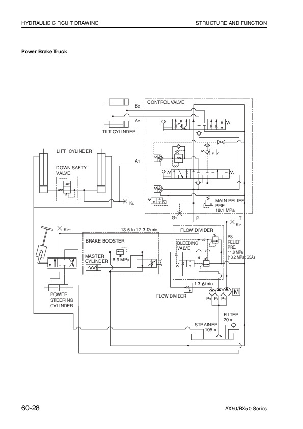
HYDRAULIC CIRCUIT DRAWING…299
ELECTRICAL CIRCUIT DRAWING…303
80. CRITERIA FOR PERIODICAL INSPECTION AND JUDGMENT…308
ENGINE…309
POWER TRAIN…315
TRAVELING SYSTEM…319
STEERING SYSTEM…321
BRAKING SYSTEM…323
WORK EQUIPMENT…326
HYDRAULIC SYSTEM…328
CHASSIS AND SAFETY SYSTEM…331
OVERALL TEST…331
90. CONVERSION TABLE…332
MILLIMETERS TO INCHES…333
INCHES TO MILLIMETERS…333
CUBIC METERS TO CUBIC YARDS…334
CUBIC YARDS TO CUBIC METERS…334
LITER TO U.S GALLON…335
U.S. GALLON TO LITER…335
LITER TO U.K GALLON…336
U.K. GALLON TO LITER…336
KILOGRAM TI POUND…337
POUND TO KILOGRAM…337
KG/CM 2 TO IB /IN 2…338
KGM TO FT. IB…339
TEMPERATURE…340

Komatsu Forklift AX50, BX50 Series Repair Service Manual


INSTANT DOWNLOAD


Posted on

Komatsu Forklift Series 4032 (FB13M-2R, FB15-2R, FB15M-2R, FB16-2R, FB16M-2R, FB18-2R, FB18M-2R, FB20-2R, FB20M-2R) Workshop Service Repair Manual


INSTANT DOWNLOAD


Complete service repair manual with Electrical Wiring Diagrams for Komatsu Forklift Series 4032 (FB13M-2R, FB15-2R, FB15M-2R, FB16-2R, FB16M-2R, FB18-2R, FB18M-2R, FB20-2R, FB20M-2R), with technical information to maintain, diagnose, repair, and service like professional mechanics.

Komatsu Forklift Series 4032 (FB13M-2R, FB15-2R, FB15M-2R, FB16-2R, FB16M-2R, FB18-2R, FB18M-2R, FB20-2R, FB20M-2R) workshop service repair manual includes:
* Numbered table of contents easy to use so that you can find the information you need fast.
* Detailed sub-steps expand on repair procedure information
* Numbered instructions guide you through every repair procedure step by step.
* Troubleshooting and electrical service procedures are combined with detailed wiring diagrams for ease of use.
* Notes, cautions and warnings throughout each chapter pinpoint critical information.
* Bold figure number help you quickly match illustrations with instructions.
* Detailed illustrations, drawings and photos guide you through every procedure.
* Enlarged inset helps you identify and examine parts in detail.

PRODUCT DETAILS:
Total Pages: 378 pages
File Format: PDF
Language: English

40328042305 EN – Komatsu Forklift Series 4032 (FB13M-2R, FB15-2R, FB15M-2R, FB16-2R, FB16M-2R, FB18-2R, FB18M-2R, FB20-2R, FB20M-2R) Shop Manual.pdf
604.24.128 – Komatsu ELECTRONIC EQUIPMENT FORKLIFT TRUCKS FB 12M-1R, FB 15M-1R, FB 18M-1R, FB 15-1R FB18-1R, FB 18H-1R, FB 20H-1R, FB 20GH-1R, FB 22H-1R, FB 25-1R, FB 28-1R, FB 30-1R.pdf
FB13M(V)_30H.1E(ELE)-BE1 – Komatsu Forklift Truck Controller for Electric Lift Trucks (FB13MV_16MV-1E, FB16M_18M_20M-1E, FB16_18_20-1E, FB16H_20H_25H_30H-1E, FB16GH_20GH_25GH-1E) Shop Manual 1 of 2.pdf
FB13M(V)_30H.1E(ELE)-BE1 – Komatsu Forklift Truck Controller for Electric Lift Trucks (FB13MV_16MV-1E, FB16M_18M_20M-1E, FB16_18_20-1E, FB16H_20H_25H_30H-1E, FB16GH_20GH_25GH-1E) Shop Manual 2 of 2.pdf
Komatsu Forklift MJ-2E Series (FB13 • 15MJ-2E) Shop Manual.pdf
Komatsu Forklift Truck AM-3E_AM-2E Series Service Training Material.pdf

MAIN SECTIONS
40328042305…1
Header…3
Table of contents…3
00 General Information…11
Product information…11
Instruction and maintenance manual…11
General Forklift Description…11
Definition of travel direction…12
Overall dimensions for three-wheel truck…13
Three-wheel truck technical data…14
Overall dimensions for four-wheel truck…18
Four-wheel truck technical data…19
Three-wheel truck tyre characteristics…23
Four-wheel truck tyre characteristics…23
Fork lift truck capacities – Model 1300 kg 3 wheels – with vertical masts and forks = 1400 mm max…24
Fork lift truck capacities – Model 1500 kg 3 / 4 wheels – with vertical masts and forks = 1400 mm max…27
Fork lift truck capacities – Model 1600 kg 3 / 4 wheels – with vertical masts and forks = 1400 mm max…30
Fork lift truck capacities – Model 1800 kg 3 / 4 wheels – with vertical masts and forks = 1400 mm max…33
Fork lift truck capacities – Model 2000 kg 3 / 4 wheels – with vertical masts and forks = 1400 mm max…36
Alternative lift characteristics…39
Abbreviations key…40
Tyre inflation pressure…41
Lamps…41
Battery dimensions and weights…41
Internal accessibility…42
Safety features…43
Transporting the Forklift…45
Forklift towing…46
Loading and unloading the truck…47
Safety precautions…49
Description of safety symbols…49
Operations Preliminary to Maintenance…49
To avoid accidents…49
General safety Regulations…50
Safety Regulations Relative to Operating Materials…52
01 Service…55
Servicing…55
Preliminary operations before commissioning…55
Synoptic Table of Maintenance Operations…55
Supply Table…56
02 Diagnostics…57
Diagnostic software…57
Connection between the diagnostics PC and the forklift …57
Software…58
Description of the menus in the WINPCCONSOLE software…59
Description of the PARAMETER menu …63
Description of the TESTER menu…68
TESTER / Diagnostics Function…69
Parameters…72
Introduction…72
Parameters of the DUAL AC module…72
Parameters of the AC2 FLASH module…78
…80
…81
Parameters of the ECO DISPLAY module…81
Parameterisation of the drive function…85
Parameterisation of the steering function…86
Parameterisation of the electric braking function…87
Parameterisation of the battery state monitoring function…88
Parameterisation of the lifting function…88
Parameterisation of the hydraulically assisted steering function…89
Parameterisation of the tilt, side shift (SLI) and 4th lever functions…90
Alarms…91
State of the truck during an alarm situation…91
…91
…92
Alarms list…93
Analogue signals…108
Summary of signals from the analogue transducers…108
11 Traction motor…111
Asynchronous motors…111
Features of the asynchronous motors …111
Checking the asynchronous motors …113
Front axle motors…114
Traction motor technical data…114
Traction…114
Traction motor…116
Drive motor checks…118
Drive motor decomposition…120
Encoder…122
Replacing the traction encoder…122
Electrical connections of the traction motors…123
Temperature sensor KTY84…124
Insulation testing of traction motor…126
22 Transmission…127
Front axle…127
Front axle technical data…127
Removal of front axle with traction motors…130
Front axle reassembly…133
Reducer…134
Front axle reducer gearbox topography…134
Front axle reduction gear disassembly/reassembly…135
Removal / reassembly of the drive wheel reducer gearbox…136
Check reducer gearbox oil level…137
Reducer gearbox oil change…138
31 Truck…139
Counterweight…139
Counterweight removal…139
Counterweight reassembly…144
Covers…146
Cover topography…146
Side covers removal / reassembly…147
Battery cover removal / reassembly…148
Step plate removal / reassembly…150
Distributor cover removal / reassembly…152
Batteries…155
Battery removal…155
34 Driver's seat…157
Overhead guard…157
Removal of the overhead guard…157
Reassembly of the overhead guard…159
Fairings…160
Removal / reassembly of the steering column panelling…160
Removal / reassembly of the control panel panelling…161
42 Steering system…165
Steering distributor…165
Steering distributor technical data…165
Removal / reassembly of the steering distributor…167
Steering distributor pressure switch technical data…169
Replacing the steering distributor pressure switch…170
Steering column…171
Removal / reassembly of the steering column…171
Fifth-wheel steering axle…175
Three-wheel truck rear axle technical data…175
Three-wheel truck axle removal…178
Three-wheel truck axle reassembly…181
Three-wheel axle disassembly…183
Three-wheel truck potentiometer technical data…187
Replacement of the three-wheel steering axle potentiometer…189
Four-wheel truck axle technical data…190
Four-wheel axle removal…191
Four-wheel truck axle reassembly…192
Four-wheel axle disassembly…194
Four-wheel truck potentiometer technical data…199
Replacing the four-wheel truck potentiometer…200
Lubricating the steering axle…205
46 Wheels and tyres…207
General information…207
Safety regulations for wheels and rims…207
General information for changing tyres…207
Tyrewear check…209
Wheel change…210
Wheel change…210
Wheel decomposition…213
Disassembly/assembly of tyres on rims with movable flange…213
Quick tyres assembly/disassembly…214
Tightening torques…216
Check wheel nut tightness (every 10 hours during run-in)…216
49 Braking system…217
Parking brake…217
Removal / reassembly of the parking brake lever…217
Parking brake control cable replacement…219
Replacing the parking brake microswitch…221
Parking brake adjustment…223
Service brake…224
Service brake pedal removal…224
Service brake pedal reassembly…225
Stop lights microswitch replacement…226
Replacing the service brake pedal potentiometer…226
Braking group…228
Removing / installing the brake group…228
50 Controls…233
Accelerator pedal…233
Accelerator pedal potentiometer…233
56 Display elements…235
DISPLAY…235
Plate data…235
Connector…235
Multifunction panel…236
Setting the date and time…242
Speed reductions…246
Functionality of the display buttons…247
Data modification pushbutton functions…249
Multifunction panel removal / reassembly…250
Alarms…251
60 Electronic system…255
Software versions…255
Reference software versions…255
Electronic traction system…256
Characteristics of the electronic drive system…256
Plate data: traction…257
Connectors…257
Closing the general contactor…260
Thermal sensor operation…260
Hydraulic functions electronic system…261
Functions of the AC2 module…261
Plate data: pump…262
AC2 Connectors…262
Control of the general contactor…263
Lowering solenoid valve operation…264
Thermal sensor operation…264
Types of hours counters…265
Types of hour counters:…265
Hours counter management in case of electronic system replacement …265
Resetting the machine hours…266
Electrical system components…267
Electronics panel technical data…267
Electronics panel removal / reassembly…267
Protection of the electrical system…272
Emergency pushbutton …273
Replacing the emergency stop button…273
Assembly / disassembly of the lights switch (option)…274
Lamp replacement (if applicable)…276
Work light replacement procedure (optional)…277
Contactors…278
Location of Fuses…279
Changing a fuse…280
DC/DC Converter …281
Buzzer…282
Fans…282
Encoder description…282
71 Hydraulic components…285
Hydraulic circuit…285
Layout of hydraulic parts…285
Hydraulic system assembly diagram…286
Pump motor…289
Pump motor technical data…289
Pump motor removal…290
Pump motor reassembly…294
Replacing the pump…295
Replacing the pump motor encoder …297
Replacing the pump motor temperature sensor…298
Oil tank…299
Hydraulic oil tank…299
Oil tank removal / reassembly…300
Check hydraulic tank oil level…303
Hydraulic distributor…305
Hydraulic distributor technical data…305
Hydraulic distributor removal / reassembly…306
Replacing the hydraulic distributor probe…309
Valves…310
Safety valve (load lowering block) (VBDC)…310
Safety valve layout…311
Tilt cylinders…317
Tilt cylinders…317
Tilt cylinder removal / reassembly…317
Air bleeding of the tilt cylinders…320
80 Lifts…321
Lifts…321
Technical data for service…321
Lift typologies…322
Simplex Lift…325
Duplex Lift…329
Triplex Lift…334
Load chain locking device…340
Fork carriage retaining device…340
Assembly of the mast / carriage support rollers…340
Check…342
Disassembly of the Simplex lift cylinder…343
Disassembly of the side cylinders of the Duplex lift…344
Disassembly of the side cylinders of the Triplex lift…346
Duplex / Triplex central cylinder…348
Limit stop dampers…350
Disassembly of the fork carriage…351
Tilt cylinder…352
Lift disconnection…354
Lift reassembly…357
Air bleeding of the lift cylinders…358
Lift cylinders…360
Annex…369
A Diagrams…371
Wiring diagrams…371
Electrical circuit diagram 40328020002…371
Electrical connection diagram 40328020001…373
Hydraulic diagrams…375
Hydraulic diagram 40328082502…375


INSTANT DOWNLOAD


Posted on

Komatsu Forklift Series 4022 (FB 20H-2R, FB 20HG-2R) & Series 4023 (FB 25H-2R, FB 30H-2R) Repair Service Manual


INSTANT DOWNLOAD


Complete service repair manual with Electrical Wiring Diagrams for Komatsu Forklift Series 4022 (FB 20H-2R, FB 20HG-2R) & Series 4023 (FB 25H-2R, FB 30H-2R), with all the technical information to maintain, diagnose, repair, rebuild like professional mechanics.

Komatsu Forklift Series 4022 (FB20H-2R, FB20HG-2R) & Series 4023 (FB25H-2R, FB30H-2R) workshop service repair manual includes:
* Numbered table of contents easy to use so that you can find the information you need fast.
* Detailed sub-steps expand on repair procedure information
* Numbered instructions guide you through every repair procedure step by step.
* Troubleshooting and electrical service procedures are combined with detailed wiring diagrams for ease of use.
* Notes, cautions and warnings throughout each chapter pinpoint critical information.
* Bold figure number help you quickly match illustrations with instructions.
* Detailed illustrations, drawings and photos guide you through every procedure.
* Enlarged inset helps you identify and examine parts in detail.

PRODUCT DETAILS:
Total Pages: 350 pages
File Format: PDF
Language: English

60424171 EN – Komatsu Forklift Series 4022 (FB 20H-2R, FB 20HG-2R) & Series 4023 (FB 25H-2R, FB 30H-2R) Shop Manual.pdf

MAIN SECTIONS
Chapter 00 INTRODUCTION
Chapter 10 TECHNICAL OPERATING INFORMATION
Chapter 20 CHECKS AND ADJUSTMENTS
Chapter 30 REMOVAL AND INSTALLATION OF PARTS
Chapter 40 MASTS
Chapter 50 ELECTRICAL SECTION

40248042304……1
Header……3
Table of contents……3
00 General information……9
Product information……9
Instruction and maintenance manual……9
Definition of Direction of Travel……10
General Forklift Description……10
Overall dimensions……11
Technical Data……11
Tyre characteristics……14
Forklift capacities – Model 2200 kg – Masts vertical with forks = 1400 mm max……15
Forklift capacities – Model 2500 kg short pitch – Masts vertical with forks = 1400 mm max……17
Forklift capacities – Model 2500 kg long pitch – Masts vertical with forks = 1400 mm max……19
Forklift capacities – Model 3000 kg – Masts vertical with forks = 1400 mm max……21
Alternative lift characteristics……23
Abbreviations key……24
Pneumatic tyre inflation pressure……24
Lamps……24
Battery dimensions and weights……25
Internal accessibility……26
Safety Devices……27
Transporting the Forklift……29
Forklift Towing……30
Loading and Unloading the Forklift……31
Safety precautions……32
Description of safety symbols……32
Operations Preliminary to Maintenance……32
To avoid accidents……32
General safety Regulations……33
Safety Regulations Relative to Operating Materials……36
01 Service……37
Maintenance……37
Preliminary operations before commissioning……37
Synoptic Table of Maintenance Operations……37
Supply Table……38
02 Diagnostics……39
Diagnostic software……39
Connection between the diagnostics PC and the forklift ……39
Software……40
Description of the menus in the WINPCCONSOLE software……42
Description of the PARAMETER menu ……46
Description of the TESTER menu……51
Parameters……53
Introduction……53
Parameters of the DUAL AC Master module ……54
AC3 module parameters……60
Smart Display……65
TESTER Function……69
Speed reductions……72
Alarms……73
General information on the alarms……73
Alarms of the DUAL AC module……74
Alarms of the AC3 module ……84
Alarms of the SMART DISPLAY module ……90
Analogue signals……92
Analogue signal acquisition……92
11 Drive motor……93
Asynchronous motors……93
Features of the asynchronous motors ……93
Checking the asynchronous motors ……96
Front axle motors……98
Drive motor technical data……98
Drive motor checks……101
Motor temperature sensor……104
Drive motor decomposition……106
22 Gearbox……109
Front axle……109
Front axle technical data……109
Front axle layout……111
Removal of front axle with drive motors……112
Front axle reconnection……118
Front axle disassembly……119
Front axle reassembly……120
Reducer……121
Front axle reducer layout……121
Front axle reduction gear disassembly/reassembly……122
Reduction gear oil level check……125
Reducer oil change……125
31 Vehicle……127
Bonnets……127
Bonnet layout……127
Right side bonnet removal/reassembly……128
Left side bonnet removal/reassembly……129
Battery hood removal/reassembly……129
Electronic panel bonnet removal/reassembly……133
Distributor hood removal/reassembly……133
Removal/reassembly of the operator footboard……135
Counterweight……137
Counterweight disconnection……137
Counterweight reconnection……140
34 Driver's seat……141
Fairing……141
Fairing removal/reassembly……141
Steering column panels removal/reassembly……143
Protective roof……145
Removal of the protective roof……145
Protective roof refitting……149
Lamp changes……150
42 Steering system……151
Hydraulic steering circuit……151
Power steering circuit tube connection diagram……151
Steering solenoid valve……152
Steering distributor technical data……152
Steering distributor removal……154
Steering distributor reassembly……156
Steering column……158
Steering column removal/reassembly……158
Replacement of the steering column joint……159
Steering axle……161
Steering axle technical data……161
Steering axle disconnection……162
Steering axle reconnection……165
Steering axle lubrication……166
Replacement of the steering axle bearings……167
Steering axle potentiometer……177
Replacement of the steering axle potentiometer……179
Steering cylinder……180
Steering cylinder disconnection……180
Steering cylinder reconnection……182
Replacement of the steering cylinder gaskets……183
Replacement of the cylinder connecting rod ball joints……184
46 Wheel and tyres……187
Miscellaneous……187
Safety regulations for wheels and rims……187
General information for changing tyres……188
Tyrewear check……189
Changing wheels……190
Changing the front wheel……190
Changing the rear wheel……191
Wheel disassembly……192
Disassembly/assembly of tyres on rims with movable flange……192
Quick tyres assembly/disassembly……194
Tightening torques……197
Tightening torques for single wheels……197
49 Brake system……199
Service brake……199
Brake pedal……199
Brake pedal potentiometer……199
Brake pedal removal/reassembly……200
Replacement of the brake pedal spring……201
Stop micro replacement……202
Replacement of the brake pedal potentiometer……203
Service brake adjustment……205
Parking brake……206
Microswitch features……206
Parking brake removal/reassembly……206
Parking brake wire replacement……208
Replacement of the parking brake microswitch……212
Parking brake adjustment……212
Brake group……214
Brake pad replacement……214
50 Controls……217
Accelerator pedal……217
Accelerator pedal potentiometer……218
56 Display elements……221
Display……221
Multifunction panel……221
State of the display on ignition……225
State of the display during normal forklift operation……0
State of the display during an alarm situation……227
Plate data……229
Display operation ……231
60 Electrical system……233
CAN BUS……233
CAN BUS ……233
CAN BUS – Application ……236
Brake pedal potentiometer……237
Drive electrical system……239
Functions of the DUAL AC module……239
Plate data……241
DUAL AC connectors……242
Software program and parameterizations……246
Hydraulic functions electrical system……250
Functions of the AC3 module……250
Plate data……251
AC3 Connectors ……252
Software program and parameterizations……254
Electrical system components……257
Contactors……257
Fuses……258
DC/DC Converter ……259
Emergency pushbutton ……261
Buzzer……262
Fans……263
Encoder description……265
Lamps……267
Protection of the electrical system……269
71 Hydraulic equipment……271
Solenoid valve……271
Lifting hall sensor……271
Reed contacts……272
Annex……277
A Diagrams……279
Circuit diagrams……279
Electrical circuit plan – sheet 1/1……279
Hydraulic diagrams……281
Hydraulic system plan – sheet 1/1……281
Flow diagrams……283
Flow chart of functions on display……283

Komatsu Forklift Series 4022 (FB 20H-2R, FB 20HG-2R) & Series 4023 (FB 25H-2R, FB 30H-2R) Repair Service Manual


INSTANT DOWNLOAD


Posted on

Komatsu Forklift Series 4016 & Series 4017 Repair Service Manual


INSTANT DOWNLOAD


Complete service repair manual with Electrical Wiring Diagrams for Komatsu Forklift Series 4016 (FB12M-2R, FB15M-2R, FB18M-2R) & Series 4017 (FB15-2R, FB18-2R), with all the technical information to maintain, diagnose, repair, and rebuild like professional mechanics.

Komatsu Forklift Series 4016 (FB 12, FB 15, FB 18 M-2R) & Series 4017 (FB 15, FB 18-2R) workshop service repair manual includes:
* Numbered table of contents easy to use so that you can find the information you need fast.
* Detailed sub-steps expand on repair procedure information
* Numbered instructions guide you through every repair procedure step by step.
* Troubleshooting and electrical service procedures are combined with detailed wiring diagrams for ease of use.
* Notes, cautions and warnings throughout each chapter pinpoint critical information.
* Bold figure number help you quickly match illustrations with instructions.
* Detailed illustrations, drawings and photos guide you through every procedure.
* Enlarged inset helps you identify and examine parts in detail.

PRODUCT DETAILS:
Total Pages: 345 pages
File Format: PDF
Language: English

60424131 GB – Komatsu Forklift Series 4016 (FB 12 • 15 • 18 M-2R) & Series 4017 (FB 15 • 18-2R) Shop Manual.pdf

MAIN SECTIONS
Chapter 00 Introduction
Chapter 10 Technical operating information
Chapter 20 Checks and adjustments
Chapter 30 Removal and installation of parts
Chapter 31 Masts
Chapter 40 Electrical section

Komatsu Forklift Series 4016 & Series 4017 Repair Service Manual


INSTANT DOWNLOAD


Posted on

Komatsu 4D98 Series, 4D106 Series, S4D106 Series Diesel Engine Repair Service Manual


INSTANT DOWNLOAD


Complete service repair manual with Electrical Wiring Diagrams for Komatsu 4D98 Series, 4D106 Series, S4D106 Series Diesel Engine, with all the technical information to maintain, diagnose, repair, rebuild like professional mechanics.

Komatsu 4D98 Series, 4D106 Series, S4D106 Series Diesel Engine workshop service repair manual includes:
* Numbered table of contents easy to use so that you can find the information you need fast.
* Detailed sub-steps expand on repair procedure information
* Numbered instructions guide you through every repair procedure step by step.
* Troubleshooting and electrical service procedures are combined with detailed wiring diagrams for ease of use.
* Notes, cautions and warnings throughout each chapter pinpoint critical information.
* Bold figure number help you quickly match illustrations with instructions.
* Detailed illustrations, drawings and photos guide you through every procedure.
* Enlarged inset helps you identify and examine parts in detail.

WEBD4D9801 – 4D98 Series, 4D106 Series, S4D106 Series Diesel Engine Shop Manual.pdf

PRODUCT DETAILS:
Total Pages: 182 pages
File Format: PDF
Language: English

MAIN SECTIONS
01 GENERAL
02 TROUBLESHOOTING
03. INSPECTION AND ADJUSTMENT
04. ENGINE BODY
05. LUBRICATION SYSTEM
06. COOLING SYSTEM
07. FUEL INJECTION PUMP/GOVERNOR
08. TURBOCHARGER (FOR 4TNE106T)
09. STARTING MOTOR
10. ALTERNATOR
11. SPECICAL SERVICE TOOLS
12. SERVICE STANDARDS

MAIN MENU…..0
FOREWORD …..4
FOR SAFE SERVICING…..5
PRECAUTIONS FOR SAFE SERVICING…..6
  (A) Service Shop (Place) …..6
  (B) Working Wear …..7
  (C) Tools to Be Used …..7
  (D) Use of Genuine Parts, Oil and Grease …..7
  (E) Bolt and Nut Tightening Torques …..7
  (F) Electrical Parts …..8
  (G) Waste Treatment …..8
  (H) Handling the Product …..9
CONTENTS …..10
1.  GENERAL …..11
  1.1 Engine Nomenclature …..12
  1.2  Specifications …..13
  1.3 Fuel  Oil,  Lubricating Oil  and Cooling Water …..17
  1.4 Engine External Views…..19
  1.5 Structural Description…..20
  1.6 How to Read This Manual…..21
    (1) Range of Operation Explanation…..21
    (2) How to Read The Explanations…..21
    (3) Definition of Terms…..22
    (4) Abbreviations…..22
  1.7 Precautions for Service Work…..23
  1.8 Tightening Torques for Standard Bolts and Nuts…..24
2.  TROUBLESHOOTING …..25
  2.1 Quick Reference Table for Troubleshooting…..26
  2.2 Troubleshooting by Measuring Compression Pressure …..29
    (1) Compression pressure measurement method…..29
    (2) Standard compression pressure…..29
    (3) Engine speed and compression pressure (reference)…..30
    (4) Measured value and troubleshooting…..30
3.  INSPECTION AND  ADJUSTMENT…..31
  3.1 Oil Inspection …..32
  3.2 Cooling Water Inspection …..32
  3.3 Inspecting Water Leak from Cooling Water System and Radiator …..32
  3.4 Fan Belt Tension Inspection and Adjustment …..33
  3.5 Adjusting the Valve Clearance …..34
  3.6 Inspecting the Fuel Injection Valve Injection Pressure and Spray  Pattern …..35
  3.7 Fuel Injection Timing Inspection and Adjustment…..39
  3.8 Adjusting the No-load Maximum (or Minimum) Revolutions …..40
  3.9 Sensor Inspection …..41
  3.10 Battery Inspection …..42
  3.11 Adjusting Operation …..44
  3.12 Long Storage …..45
  3.13 Periodic Maintenance Schedule …..46
4. ENGINE BODY …..47
  4.1 Introduction …..49
  4.2 Cylinder Head …..50
    (1) Components…..50
    (2) Disassembly procedure:…..50
    (3) Reassembly procedure:…..51
    (4) Servicing points…..51
    (5) Parts Inspection and measurement…..53
    (6) Valve seat correction…..56
    (7) Valve guide replacement…..58
    (8) Valve stem seal replacement…..58
  4.3 Gear Train and Camshaft …..59
    (1) Components…..59
    (2) Disassembly procedure:…..59
    (3) Reassembly procedure:…..59
    (4) Servicing points…..60
    (5) Parts inspection and measurement…..62
    (6) Oil seal replacement…..64
    (7) Camshaft bushing replacement…..64
  4.4 Cylinder block…..65
    (1)  Components…..65
    (2)  Disassembly procedure…..65
    (3)  Reassembly procedure…..65
    (4)  Servicing points…..66
    (5)  Parts inspection and measurement…..69
    (6)  Cylinder bore correction…..77
    (7)  Piston pin bushing replacement…..78
    (8)  Oil seal replacement…..78
5. LUBRICATION SYSTEM…..79
  5.1 Lubrication System Diagram …..80
  5.2 Trochoid Pump Components …..80
  5.3 Disassembly (Reverse the procedure below for assembly) …..81
  5.4 Servicing Points …..81
  5.5 Parts Inspection and Measurement …..81
6. COOLING SYSTEM…..82
  6.1 Cooling Water System …..83
  6.2 Cooling Water Pump Components …..83
  6.3 Disassembly (Reverse the procedure below for assembly)…..84
  6.4 Servicing Points …..84
7. FUEL  INJECTION PUMP/GOVERNOR…..85
  7.1 Introduction …..86
  7.2 Fuel Injection Pump …..86
    (1) Fuel system diagram…..86
    (2) Components…..87
    (3) Disassembly procedure:…..87
    (4) Assembly procedure…..88
    (5) Servicing points…..88
    (6) Parts inspection and measurement…..90
  7.3 Fuel Injection Valve …..92
  7.4 Fuel Feed Pump…..92
    (1) Components…..92
    (2) Disassembly procedure (Reverse the procedure below for assembly.)…..92
    (3) Parts inspection and measurement…..92
  7.5 Governor…..93
    (1) Components…..93
    (2) Disassembly procedure (Reverse the procedure for assembly.)…..93
    (3) Parts inspection and measurement…..94
  7.6 Special Service Tools for Disassembly/Assembly …..94
8. TURBOCHARGER  (FOR  4TNE106T) …..95
  8.1 Structure and Functions …..97
    (1) Structural and functional outline…..97
    (2) Structure…..98
    (3) Components…..99
  8.2 Service Standards …..100
    (1) Service standards…..100
    (2) Tightening torque…..100
  8.3 Periodic Inspection Procedure …..101
    (1) Periodic inspection intervals…..101
    (2) Inspection procedure…..101
    (3) Waste gate valve adjustment procedure…..102
  8.4 Disassembly Procedure …..104
    (1) Preparation for disassembly…..104
    (2) Inspection before disassembly…..105
    (3) Disassembly…..105
  8.5 Washing and Inspection procedure…..106
    (1) Washing…..106
    (2) inspection procedure…..107
  8.6 Reassembly Procedure …..110
    (1) Preparation for reassembly…..110
    (2) Reassembly…..110
  8.7 Handling after Disassembly and Reassembly …..112
  8.8 Troubleshooting …..113
9.  STARTING MOTOR …..115
  9.1 FOR 4TNE94/98…..117
    9.1.1 Specifications…..117
    9.1.2 Components…..118
    9.1.3 Troubleshooting…..119
    9.1.4 Names of parts and disassembly procedure…..120
    9.1.5 Inspection and Maintenance…..124
      (1) Armature…..124
      (2) Field coil…..126
      (3) Brush…..126
      (4) Brush holder…..127
      (5) Magnetic switch…..127
      (6) Pinion clutch…..128
    9.1.6 Service standards…..130
    9.1.7 Assembly…..131
    9.1.8 Characteristic test…..133
  9.2 FOR 4TNEl06(T) …..134
    9.2.1 Specifications…..134
    9.2.2 Configuration drawing…..134
    9.2.3 Troubleshooting…..135
    9.2.4 Component names and disassembly procedure…..136
    9.2.5 Disassembly procedure…..137
    9.2.6 Inspection and maintenance…..139
      (1) Armature…..139
      (2) Field coil…..141
      (3) Brush…..141
      (4) Magnetic switch continuity test…..142
      (5) Pinion…..143
      (6) Ball bearing…..143
    9.2.7 Assembly…..143
    9.2.8 Adjustment…..144
    9.2.9 Service standards…..145
10.  ALTERNATOR …..146
  10.1 For 4TNE94/98 …..147
    10.1.1 Specifications …..147
    10.1.2 Section view…..148
    10.1.3 Troubleshooting…..149
    10.1.4 Parts names and disassembly procedure …..150
    10.1.5 Inspection and overhaul …..153
      (1) Diode…..153
      (2) Rotor…..153
      (3) Stator…..154
      (4) Brush…..155
      (5) Check of IC regulator…..155
    10.1.6 Assembly …..157
    10.1.7 Service standards …..158
    10.1.8 Performance test …..159
  10.2 For 4TNE106(T) …..160
    10.2.1 Specifications  (1) …..160
    10.2.2 Exploded View …..161
    10.2.3 Troubleshooting …..162
    10.2.4 Disassembly Procedure …..163
    10.2.5 Inspection and Maintenance …..164
    10.2.6 Reassembly Procedure …..165
    10.2.7 Performance Test …..166
11.  SPECIAL SERVICE TOOLS…..168
  11.1 Special Tools …..169
  11.2 Measuring Instruments …..171
12.  SERVICE STANDARDS …..174
  12.1 Engine Tuning …..175
  12.2 Engine Body …..176
    (1) Cylinder head…..176
    (2) Gear train and camshaft…..177
    (3) Cylinder block…..178
  12.3 Lubricating Oil System (Trochoid Pump) …..180
  12.4 Tightening Torques for Main Bolts and Nuts …..181

Komatsu 4D98 Series, 4D106 Series, S4D106 Series Diesel Engine Repair Service Manuals


INSTANT DOWNLOAD