Posted on

Hyster Forklift Trucks F003 (H40-60JS & H2.00-3.00JS Europe) Repair Service Manuals


INSTANT DOWNLOAD


Complete service repair manual for Hyster F003 (H40-60JS & H2.00-3.00JS Europe) Forklift Trucks, with all the technical information to maintain, diagnose, repair, and rebuild like professional mechanics.

Hyster F003 (H40-60JS & H2.00-3.00JS Europe) workshop service repair manual includes:
* Numbered table of contents easy to use so that you can find the information you need fast.
* Detailed sub-steps expand on repair procedure information
* Numbered instructions guide you through every repair procedure step by step.
* Troubleshooting and electrical service procedures are combined with detailed wiring diagrams for ease of use.
* Notes, cautions and warnings throughout each chapter pinpoint critical information.
* Bold figure number help you quickly match illustrations with instructions.
* Detailed illustrations, drawings and photos guide you through every procedure.
* Enlarged inset helps you identify and examine parts in detail.

Hyster F003 (H40-60JS & H2.00-3.00JS Europe) Service Manual.pdf

Total Pages: 577 + 525 pages
File Format: PDF
Language: English

F003 (H2.00-3.00JS Europe)…2
100179…4
INTRODUCTION…4
General…4
Description…4
DISASSEMBLY AND ASSEMBLY…5
Overhead Guard…5
Hood and Seat Removal…6
Counterweight…6
Engine and Transmission…6
REPAIRS…8
Fuel and Hydraulic Tanks…8
Decal Replacement…9
120018…13
INTRODUCTION…13
GENERAL…13
DESCRIPTION AND OPERATION …13
REPAIRS…14
REMOVAL…14
INSPECTION…14
INSTALLATION…15
ADJUSTMENTS…17
ADJUSTING THE HEIGHT OF THE CLUTCH PEDAL…17
ADJUSTING THE CLEARANCE BETWEEN THE RELEASE BEARING AND THE PRESSURE PLATE LEVERS…17
TROUBLESHOOTING…18
130043…20
INTRODUCTION…20
General…20
REPAIRS…21
REMOVAL…21
DISASSEMBLY…21
CLEANING…29
INSPECTION…30
ASSEMBLY…30
Assembling the Control Valve…30
Assembling the Differential…33
Assembling the Transmission…41
Installation…45
MONOTROL Pedal…45
CHECKS AND ADJUSTMENTS…46
Checking the MONOTROL Pedal for Leakage…46
MONOTROL Pedal…46
Stall Test…46
Checking the Oil Pressures…47
MONOTROL Pressure…48
Clutch Apply Pressure…50
Inching Spool Operation…51
Torque Converter and Oil Cooler Pressure…51
CHECKING THE POWERSHIFT ELECTRICAL CIRCUIT…51
CHECKING THE CIRCUIT FOR THE DIRECTION CONTROL LEVER…52
ADJUSTING THE OIL SUMP TUBE…53
TROUBLESHOOTING…53
Pressure Tests…56
Troubleshooting the Differential…57
130059…59
INTRODUCTION…59
GENERAL…59
DESCRIPTION…59
REPAIRS…62
REMOVAL…62
DISASSEMBLY…62
CLEANING…69
INSPECTION…69
ASSEMBLY…69
INSTALLATION…77
TROUBLESHOOTING…77
SPECIFICATIONS…78
140049…79
INTRODUCTION…79
GENERAL…79
DESCRIPTION…79
REPAIRS…79
DISASSEMBLY…80
CLEANING…82
ASSEMBLY…82
TROUBLESHOOTING…84
160010…85
INTRODUCTION…85
DESCRIPTION…85
GENERAL…85
REPAIRS…86
STEERING AXLE…86
Removal…86
Installation…87
STEERING CYLINDER…87
Removal…87
Service…88
Installation…88
HUBS…88
Removal…88
Installation…89
SPINDLES…89
Removal…89
Installation…90
CHECKS AND ADJUSTMENTS…90
REMOVE THE AIR FROM THE STEERING SYSTEM…90
SET THE PRESSURE RELIEF VALVE…90
S/H1.25-1.75XL (S/H25-35XL) and H2.00-3.00XL (H40-60XL)…90
H2.00-3.00J (H40-60J) WITH OIL CLUTCH TRANSMISSION…90
H2.00-3.00J (H40-60J) With Powershift Transmission…90
TROUBLESHOOTING…92
160054…93
INTRODUCTION…93
GENERAL…93
DESCRIPTION…93
OPERATION…93
REPAIRS…93
STEERING WHEEL AND COLUMN ASSEMBLY…93
TYPE "A" STEERING COLUMN ASSEMBLY…95
Removal And Disassembly…95
Assembly And Installation…95
TYPE "A" STEERING COLUMN…96
TYPE "A" STEERING COLUMN…97
TYPE "B" STEERING COLUMN…98
Removal And Disassembly…98
Assembly And Installation…98
TYPE "B" STEERING COLUMN…99
Disassembly of Steering Control Unit…100
Cleaning of Steering Control Unit…100
Assembly of Steering Control Unit…102
CHECKS AND ADJUSTMENTS…105
REMOVE AIR FROM THE SYSTEM…105
TROUBLESHOOTING…106
180013…107
INTRODUCTION…107
GENERAL…107
DESCRIPTION…107
REPAIRS…107
REMOVAL AND DISASSEMBLY…107
CLEANING …108
ASSEMBLY…108
CHECKS AND ADJUSTMENTS…108
CHECKS…108
180080…109
INTRODUCTION…109
GENERAL…109
DESCRIPTION AND OPERATION…110
REPAIRS…110
REMOVAL AND DISASSEMBLY…110
CLEANING…111
INSPECTION…112
ASSEMBLY…112
CHECKS AND ADJUSTMENTS…114
BRAKE SHOES…114
Parking Brake…114
Seat Actuated Park Brake, J40–60AS…114
Removing The Air From The Brake System…115
TROUBLESHOOTING…116
190064…119
INTRODUCTION…119
GENERAL…119
DESCRIPTION…119
REPAIRS…119
REMOVAL AND DISASSEMBLY…119
CLEANING…121
INSPECTION…121
ASSEMBLY AND INSTALLATION…121
TROUBLESHOOTING…123
GENERAL…123
190097…124
INTRODUCTION…124
DESCRIPTION…124
OPERATION…124
Flow Control Valve…126
Relief Valve…126
REPAIRS…127
REMOVAL…127
DISASSEMBLY…127
CLEANING…129
INSPECTION…129
ASSEMBLY…130
INSTALLATION…131
CHECKS AND ADUSTMENTS…132
CHECK THE OUTPUT OF THE PUMP…132
CHECK FOR AIR IN THE HYDRAULIC SYSTEM…132
TROUBLESHOOTING…134
200065…137
INTRODUCTION…137
General…137
Description…137
Hydraulic Control Valve…143
REPAIRS…147
Disassembly…147
Cleaning…147
Inspection…147
Assembly…148
CHECKS AND ADJUSTMENT…149
Relief Valve…149
TROUBLESHOOTING…151
2100103…153
INTRODUCTION…156
GENERAL…156
DESCRIPTION…156
REPAIRS…156
REMOVAL…156
DISASSEMBLY…156
CLEANING…156
ASSEMBLY…156
Tilt Cylinders for the XM and XMS Models…156
Tilt Cylinders with O-Ring or Single Lip Seals…158
Tilt Cylinders for H700-800A and Early Model H700-920B…158
INSTALLATION…158
Tilt Cylinders with Chevron Packing…158
CHECKS AND ADJUSTMENTS…162
CHECK THE TILT CYLINDERS FOR LEAKS…162
ADJUST THE TILT CYLINDER STROKE AND THE MAST TILT ANGLE…162
TROUBLESHOOTING…165
2200106…168
INTRODUCTION…168
GENERAL…168
DESCRIPTION AND OPERATION…168
REPAIRS…170
REMOVAL…170
DISSASEMBLY…170
CLEANING…171
ASSEMBLY…171
INSTALLATION…171
CHECKS AND ADJUSTMENTS…172
GENERAL…172
TROUBLESHOOTING…174
2200107…176
HIGH ENERGY IGNITION (HEI)…176
DESCRIPTION…176
REPAIRS…178
DISTRIBUTOR…178
Removal…178
Disassembly…178
Assembly…183
INSTALLATION, IF THE CRANKSHAFT WAS NOT ROTATED WHEN DISTRIBUTOR WAS REMOVED…184
INSTALLATION, IF THE CRANKSHAFT WAS ROTATED WHEN THE DISTRIBUTOR WAS REMOVED…185
IGNITION COIL…185
Removal, Some 4 and 6 Cylinder Models…185
Installation, Some 4 and 6 Cylinder Models…186
Removal, V8, Some 4 and 6 Cylinder Models…186
Installation, V8, Some 4 and 6 Cylinder Models…187
ELECTRONIC MODULE…188
Removal…188
Installation…188
SENSING COIL…189
Removal…189
Installation…189
SPARK PLUGS…189
Removal…189
Installation…190
CHECKS AND ADJUSTMENTS…190
Visual Checks…190
Check The High Voltage Wires…190
Checking The Ignition Coil…190
Coil In Distributor Cap Design…190
Separate Coil Design…191
Checking The Sensing Coil…191
Check The Electronic Module…192
Ignition Timing Adjustment…192
Ignition System, GM V8-366 (6-litre)…193
Ignition Timing and Idle Speed Adjustment, GM V6-LPG (4.3-litre)…193
SPECIFICATIONS…193
TROUBLESHOOTING…194
2200143…195
INTRODUCTION…195
GENERAL…195
DESCRIPTION…195
GENERAL…195
STEERING COLUMN GAUGES, METERS AND INDICATORS…198
LED DISPLAY PANEL…198
Battery Discharge Indicators …198
Brush Wear Indicators…199
Motor Temperature Indicators…200
"LX" SERIES INSTRUMENT PANEL DISPLAY…201
Hourmeter Functions…202
Battery Indicator Function…202
Status Code Function…202
CHECKS AND ADJUSTMENTS…202
GENERAL…202
REPLACEMENT…203
GENERAL…203
METER REPLACEMENT…203
SENDER REPLACEMENT…204
Fuel Level Sender…204
Pressure And Temperature Sender…205
I.T.W. DISPLAY PANEL…205
Removal…205
SPECIFICATIONS…206
TROUBLESHOOTING…207
2200144…208
ELECTRICAL WARNING DEVICES…208
GENERAL…208
DESCRIPTION…208
Operator Controlled Horns…208
System Warning Lights, Buzzers and Bells…208
Reverse Warning Horns…209
Warning Lights…209
REPLACEMENT…210
General…210
Replacing Horns or Bells…210
Replacing Horn Relay or Buzzer…210
Replacing Warning Lights…210
Light Assemblies…211
Replacing Flashing Units…211
2200153…212
ELECTRICAL SYSTEM COMPLETELY DEAD…212
STARTER DOES NOT CRANK AND SOLENOID DOES NOT PULL IN …213
STARTER DOES NOT CRANK; SOLENOID PULLS IN, DOES NOT CHATTER…215
STARTER SOLENOID CLICKS IN AND OUT WHILE ATTEMPTING TO CRANK…216
STARTER CRANKS SLOWLY…218
STARTER CRANKS AT NORMAL SPEED, BUT ENGINE DOES NOT START…219
BATTERY GOES DEAD OVERNIGHT OR OVER WEEKEND…221
CHARGING SYSTEM DOES NOT FUNCTION…222
ALTERNATOR CHARGES AT A RATE ALTHOUGH BATTERY IS LOW…225
BATTERY IS BEING OVERCHARGED…228
ONE OR MORE DASH GAUGES DO NOT WORK…229
HORN DOES NOT BLOW…233
POWERSHIFT TRANSMISSION WILL NOT ENGAGE…234
ELECTRICAL SCHEMATIC S20-30A, H20-30E…235
ELECTRICAL S30-50C…236
ELECTRICAL SCHEMATIC H30-60H GASOLINE & LPG…237
ELECTRICAL SCHEMATIC H30-60H DIESEL…239
ELECTRICAL SCHEMATIC H60-90C GASOLINE & LPG…241
ELECTRICAL SCHEMATIC H60-90C DIESEL…242
ELECTRICAL SCHEMATIC S30-60ES…243
ELECTRICAL SCHEMATIC S60-120E…244
ELECTRICAL SCHEMATIC S125-150A GASOLINE & LPG…245
ELECTRICAL SCHEMATIC S125-150A DIESEL…246
ELECTRICAL SCHEMATIC H110-150F GASOLINE & LPG…247
ELECTRICAL SCHEMATIC H110-150F DIESEL…248
ELECTRICAL SCHEMATIC H150-275H, P150200B GASOLINE & LPG…249
ELECTRICAL SCHEMATIC H150-275H, P150-200B DIESEL…250
ELECTRICAL SCHEMATIC H300A…251
ELECTRICAL SCHEMATIC H300-350B…252
ELECTRICAL SCHEMATIC H360-620B PERKINS DIESEL…253
ELECTRICAL SCHEMATIC H360-620B DETROIT DIESEL…254
ELECTRICAL SCHEMATIC H700-800A…255
ELECTRICAL SCHEMATIC P40-50A GASOLINE…257
ELECTRICAL SCHEMATIC P40-50A DIESEL…258
ELECTRICAL SCHEMATIC P60-80A GASOLINE…259
ELECTRICAL SCHEMATIC P60-80A DIESEL…260
ELECTRICAL SCHEMATIC KE GAS GASOLINE…261
ELECTRICAL SCHEMATIC KE DIESEL…262
ELECTRICAL SCHEMATIC M200-400H GASOLINE…263
ELECTRICAL SCHEMATIC M200-400H DIESEL…265
ELECTRICAL SCHEMATIC M600A…267
22002…269
INTRODUCTION…269
GENERAL…269
DESCRIPTION…269
REPAIRS…271
GENERAL…271
REMOVAL AND DISASSEMBLY (Type A)…271
CLEANING…271
ASSEMBLY (Type A)…272
REMOVAL AND DISAASSEMBLY (Type B)…274
CLEANING…276
ASSEMBLY (Type B)…276
INSTALLATION (Type A and Type B)…277
CHECKS AND ADJUSTMENTS…277
GENERAL…277
CHECK THE ALTERNATOR FOR LOW OUTPUT (Type A or Type B)…278
CHECK THE ALTERNATOR FOR HIGH OUTPUT (Type A or Type B)…279
CHECK THE CIRCUIT FOR THE BRUSHES…281
Delco Alternators…281
Motorola Alternators…281
CHECK THE DIODES…281
CHECK THE DIODE BRIDGE…281
Delco and Leece–Neville Alternators…281
Motorola Alternators…281
CHECK THE FIELD WINDING FOR THE ROTOR…282
CHECK THE WINDINGS IN THE STATOR…282
CHECK THE VOLTAGE REGULATOR…283
TROUBLESHOOTING…283
4000115…284
INTRODUCTION…284
GENERAL…284
REPAIRS…284
FORKS…284
CARRIAGE…284
Removal…284
SAFETY PROCEDURES WHEN WORKING NEAR THE MAST…285
Installation…286
MASTS…288
Removal…288
Disassembly…290
Cleaning and Inspection…294
Assembly…295
INSTALLATION…296
CHECKS AND ADJUSTMENTS…296
CHECKING FOR LEAKS IN THE LIFT SYSTEM…296
ADJUSTING THE TILT CYLINDER STROKE AND THE BACKWARD TILT ANGLE…297
LIFT CHAIN ADJUSTMENTS…297
MAST ADJUSTMENTS…298
Guide Shoe Adjustment…299
CARRIAGE ADJUSTMENT…301
TROUBLESHOOTING…303
4000135…304
SAFETY PROCEDURES WHEN WORKING NEAR THE MAST…304
LIFT CYLINDERS…307
GENERAL…307
DESCRIPTION…307
Lowering Control Valve…307
Cylinders (General)…310
Cylinders (H520-620B,H700-800A)…312
Cylinders (H360-460B)…313
Cylinders (Two-Speed)…313
REPAIRS…314
REMOVAL OF THE LIFT CYLINDER WITHOUT REMOVING THE MAST…314
Standard Masts with the Main Lift Cylinder Fastened to the Crossmember of the Inner Mast…314
Standard and Full Free-Lift Masts with the Lift Cylinder to a Crosshead…318
Masts that have Two Cylinders, A Main Lift Cylinder and a Free-Lift Cylinder…316
DISASSEMBLY…316
ASSEMBLY…318
INSTALLATION OF THE LIFT CYLINDER IN THE MAST…318
Standard Masts with the Main Lift Cylinder Fastened to the Crossmember of the Inner Mast…318
Standard and Full-Free-Lift Masts with the Lift Cylinder Fastened to a Crosshead…318
CHEVRON PACKING…319
LIFT CYLINDERS FOR VISTA MASTS…322
DESCRIPTION…322
Lowering Control Valve…324
REMOVAL…325
DISASSEMBLY…325
ASSEMBLY…325
INSTALLATION…326
Main Lift Cylinders…326
Free-Lift Cylinders…326
CHECKS AND ADJUSTMENTS…327
CHECK FOR LEAKS IN LIFT SYSTEM…327
TROUBLESHOOTING…328
SPECIFICATIONS…329
4000167…330
INTRODUCTION…330
GENERAL…330
STANDARD MASTS (Mast Assemblies Having Less Than Full Free-Lift.)…332
FULL FREE-LIFT MASTS…332
THREE-STAGE MASTS…334
FOUR-STAGE MASTS…335
SEQUENCE VALVE…335
4000197…337
INTRODUCTION…337
GENERAL…337
VISTA TWO-STAGE MASTS…339
DESCRIPTION…339
OPERATION…342
VISTA THREE-STAGE MASTS…342
DESCRIPTION…342
OPERATION…344
SEQUENCE VALVE…346
4000198…349
INTRODUCTION…349
GENERAL…349
SAFETY PROCEDURES WHEN WORKING NEAR THE MAST…349
REPAIRS…350
FORKS…350
Removal…350
CARRIAGE…350
Removal (Two-Stage and Later Production Three-Stage Carriages)…350
Removal (Carriages with Removable Stop Block)…351
Installation (Two-Stage and Later Production Three-Stage Carriages)…352
Installation (Carriages With Removable Stop Block)…352
TWO-STAGE MASTS…354
REMOVAL…354
DISASSEMBLY…355
CLEANING AND INSPECTION…356
ASSEMBLY…357
INSTALLATION…358
THREE-STAGE MASTS…358
REMOVAL…358
DISASSEMBLY…358
CLEANING AND INSPECTION…360
ASSEMBLY…360
INSTALLATION…361
LIFT AND TILT CYLINDERS…362
SIDE SHIFT CARRIAGE…362
Removal…362
Repairs…362
Installation…362
SEQUENCE VALVE…363
Removal and Disassembly…366
Cleaning…366
Assembly and Installation…366
CHECKS AND ADJUSTMENTS…367
CHECKING FOR LEAKS IN THE LIFT SYSTEM…367
ADJUSTING THE TILT CYLINDER STROKE AND THE BACKWARD TILT ANGLE…367
LIFTING CHAIN ADJUSTMENTS…368
MAST ADJUSTMENTS…369
CARRIAGE ADJUSTMENT…370
HEADER HOSE ROLLER ADJUSTMENT, 2-STAGE…371
TROUBLESHOOTING…372
TORQUE SPECIFICATIONS…373
VISTA MASTS…374
600169…375
INTRODUCTION…375
General…375
Description…375
ENGINE…375
Removal…375
Installation…376
CYLINDER HEAD AND VALVE MECHANISM…376
Cylinder Head…376
Removal…376
Repairs…377
Installation…377
Valve Guides…379
Valve Mechanism…379
Valves…379
Valve Springs…379
Rocker Arm Assembly…379
LUBRICATION…380
Oil Pump…380
Removal and Disassembly…380
Repairs…380
Assembly and Installation…380
Relief Valve…381
TIMING GEAR CASE AND CAMSHAFT…381
Timing Gear Cover…381
Removal…381
Installation…381
Idle Gears…381
Removal…381
Installation…382
Camshaft Gear and Camshaft…382
Removal…382
Installation…383
Fuel Pump Gear…383
Removal…383
Installation…384
Timing Gear Case…384
Removal…384
Installation…384
CRANKSHAFT AND MAIN BEARINGS…385
Removal…385
Installation…385
PISTONS AND PISTON RODS…386
Removal…386
Disassembly…386
Repairs…387
Assembly…387
Installation…388
CYLINDER LINERS…389
Removal …389
Installation…389
FLYWHEEL AND FLYWHEEL HOUSING…389
Removal…389
Installation…389
FUEL PUMP…389
Removal…389
Installation…390
FUEL INJECTION PUMP…390
Removal…390
Installation…390
FUEL INJECTORS…391
Checks…391
Installation…391
COOLING SYSTEM…392
Thermostat…392
Removal…392
Installation…392
Water Pump…392
Removal…392
Assembly…393
CHECKS AND ADJUSTMENTS…393
Removing Air From The Fuel System…393
Timing…394
Fuel Injection Pump…394
Valve Clearance Adjustment…397
Adjusting The Throttle Linkage…397
TROUBLESHOOTING…399
SPECIFICATIONS…400
6003…404
INTRODUCTION…404
GENERAL…404
DESCRIPTION…405
REMOVAL AND INSTALLATION OF THE ENGINE…405
CYLINDER HEAD AND MECHANISM…405
Cylinder Head, Removal…405
Cylinder Head, Disassembly…406
Cleaning And Inspection…407
Valve And Valve Seats…408
Studs For The Rocker Arms…408
Hydraulic Valve Lifters, Replacement…408
Hydraulic Valve Lifters, Cleaning And Inspection…409
Cylinder Head, Assembly…409
Cylinder Head, Installation…409
Rocker Arm Cover, Installation…410
TIMING GEAR COVER…411
Removal…411
Installation…411
CAMSHAFT…412
Removal…412
Inspection…413
Camshaft Bearings, Removal…413
Camshaft Bearings, Installation…413
DISTRIBUTOR…414
Removal…414
Installation…414
LUBRICATION SYSTEM…415
Oil Sump, Removal…415
Oil Sump, Installation…415
Oil Pump, Removal…415
Oil Pump, Disassembly and Repair…415
Oil Pump, Assembly…416
Oil Pump, Installation…416
PISTON AND CONNECTING ROD ASSEMBLIES…416
Connecting Rod Bearings, Replacement…416
Piston And Connecting Rod Assemblies, Removal…417
Disassembly…418
Piston, Cleaning And Inspection…418
Cylinder Bores, Inspection And Repair…418
Piston Rings…419
Assembly…420
Piston And Connecting Rod Assemblies, Installation…420
CRANKSHAFT…421
Main Bearings, Replacement…421
Oil Seal For The Rear Main Bearing, Replacement (GM 4-181 and 3.0L Only)…422
Oil Seal For The Rear Main Bearing, Replacement (Engines That Have A Two-Piece Oil Seal)…422
Crankshaft, Removal…423
Inspection and Repair…424
How To Check The Clearance Between The Main Bearings And Their Journals…424
Installation…425
FLYWHEEL AND FLYWHEEL HOUSING…426
Flywheel, Removal…426
Ring Gear, Replacement…427
Flywheel, Installation…427
COOLING SYSTEM…427
Coolant Pump…427
Fan Drive…428
Viscous Fan Drive…428
ENGINE SPECIFICATIONS…429
ENGINE DATA…429
CYLINDER HEAD…429
HYDRAULIC VALVE LIFTER…430
CAMSHAFT…430
PISTONS…430
CYLINDER BORE…431
CRANKSHAFT…431
CONNECTING RODS…431
COOLING SYSTEM…432
LUBRICATION SYSTEM…432
TORQUE SPECIFICATIONS…432
700626…435
COOLING SYSTEM…435
INTRODUCTION…435
DESCRIPTION…435
RADIATOR…435
RADIATOR CAP…435
THERMOSTAT…435
WATER PUMP…436
FAN AND FAN SHROUD …436
REPAIRS…436
COOLING SYSTEM CHECKS…436
Exhaust Leaks…436
RADIATOR…436
Checks…436
Cleaning The Radiator…436
Drain The Cooling System…438
Fill The Cooling System…438
WATER PUMP…438
Checks…438
THERMOSTAT…439
Checks…439
FAN AND FAN SHROUD …439
TROUBLESHOOTING…440
8000180…441
INTRODUCTION…441
General…441
MAINTENANCE SCHEDULE…441
MAINTENANCE PROCEDURES Every 8 Hours or Daily…444
Checks with the Engine Stopped…444
Hydraulic System…444
Air Cleaner…444
Engine Oil…444
Fuel Filter (Diesel)…444
Battery…445
Cooling System…445
Drive Belts…445
Tires and Wheels…446
Lift Mechanism…447
Forks…447
Lift Chains…447
Upright…448
Carriage…448
Load Backrest Extension…448
Powershift Transmission…448
Checks with the Engine Running…448
Guages and Lights…449
Powershift Transmission…449
Brakes…449
Steering System…449
Hydraulic System…451
Uprights…451
Attachments…451
Every 350 Hours or Two Months…452
Engine Oil and Filter…452
Brake Fluid…452
Hydraulic Tank Breather…452
Forks…452
Uprights…453
Other Lubrication Points…454
Every 1000 Hours or Six Months…454
Final Fuel Filter (Diesel)…454
Removing Air From The Diesel Fuel System…454
Ignition System (Gas Engine…455
PCV Valve (Gas Engine)…455
Every 2000 Hours or Yearly…456
PCV Valve (Gas Engine)…456
PCV Valve (Diesel Engine)…456
Differential…457
Adjusting The Oil Clutch Pedal…457
Hydraulic System…457
Changing The Gasoline Fuel System…458
Changing The Fuel Filter for LPG…458
WHEELS AND TIRES…459
Drive Tires…459
Steering Tires…462
8000181…463
8000182…466
8000231…472
INTRODUCTION…472
NOMENCLATURE, THREADS…472
STRENGTH IDENTIFICATION…473
TABLE 1. BOLTS AND SCREWS…473
TABLE 2. STUDS AND NUTS…474
TABLE 3. TORQUE NUTS…475
TABLE 4. TORQUE NUTS WITH NYLON INSERT…476
TABLE 5. TORQUE VALUES FOR INCH FASTENERS…477
TABLE 6. TORQUE VALUES FOR METRIC FASTENERS…478
90011…481
INTRODUCTION…481
GENERAL…481
DESCRIPTION…481
OPERATION…482
The Float System…482
The Idle System…482
The Main Metering System (GM 6-250)…483
The Power System (GM 6-250)…484
The Accelerator Pump System…484
Choke System…484
REPAIRS…485
REMOVAL…485
DISASSEMBLY…485
Cleaning…485
ASSEMBLY…485
INSTALLATION…485
GOVERNOR (ELECTONIC) (IMPCO Type) (Later Units)…490
GOVERNOR (PNEUMATIC) (Early Units)…491
CHECKS AND ADJUSTMENTS…492
GENERAL…492
ADJUST THE CHOKE CONTROL…492
ADJUST THE IDLE SPEED…492
ADJSUT THE IDLE MIXTURE…493
ADJUST THE FAST IDLE…493
ADJUST THE THROTTLE LINKAGE,(Later Models)…494
ADJUST THE THROTTLE LINKAGE,(Early Models)…495
GOVERNOR (IMPCO Type) (Later GM 4-153 and 4-181 Engines Only)…495
Check the Governor…495
GOVERNOR (AISAN Type) (Early GM Engines Only)…496
Checks…497
Adjustments…497
GOVERNOR (HOOF Type) (Early GM Engines Only)…497
Adjust the Governor…497
TROUBLESHOOTING…499
90015…500
THE LPG FUEL SYSTEM (IMPCO CA 50, CA 100)…500
GENERAL…500
DESCRIPTION…500
Fuel Tank…501
Fuel Filter And Fuel Valve Unit…502
Vaporizer…502
The IMPCO CA 100 Carbureto…504
IMPCO CA 50 Carburetor…506
The Governor (GM Engines Only)…507
Governor With Electronic Controller…508
REPAIRS…509
LPG TANK…509
Removal…509
Installation…510
REPLACE THE HOSES…510
HYDROSTATIC RELIEF VALVE…510
Removal and Installation…510
FILTER UNIT…511
Replacement Of the Fuel Filter Element…511
Replacement of the Diaphragm and Fuel Valve…512
VAPORIZER…512
Removal…512
Disassembly…512
Cleaning…512
Inspection…512
Assembly…514
Installation…514
CARBURETOR (IMPCO CA 100)…516
Removal…516
Disassembly…516
Cleaning…516
Assembly…516
Installation…519
CARBURETER (IMPCO CA 50)…518
Removal…518
Disassembly…518
Cleaning…519
Inspection…519
Assembly (See FIGURE 26.)…519
Installation…519
CHECKS AND ADJUSTMENTS…520
CHECK THE FILTER UNIT…520
CHECK THE VAPORIZER…520
Pressure Reducer Valve…520
Vapor Valve…520
ADJUST THE CARBURETOR…520
Idle Mixture…520
Idle Speed…520
Power Mixture…520
ADJUST THE GOVERNOR (GM Engines Only)…521
Checks…521
Main Adjusting Screw…521
Secondary Adjusting Screw…521
AISAN Governor…522
Adjustment, AISAN Governor…522
TROUBLESHOOTING…523
F003 (H40-60JS)…527
100179…529
INTRODUCTION…529
General…529
Description…529
DISASSEMBLY AND ASSEMBLY…530
Overhead Guard…530
Hood and Seat Removal…531
Counterweight…531
Engine and Transmission…531
REPAIRS…533
Fuel and Hydraulic Tanks…533
Decal Replacement…534
120018…538
INTRODUCTION…538
GENERAL…538
DESCRIPTION AND OPERATION …538
REPAIRS…539
REMOVAL…539
INSPECTION…539
INSTALLATION…540
ADJUSTMENTS…542
ADJUSTING THE HEIGHT OF THE CLUTCH PEDAL…542
ADJUSTING THE CLEARANCE BETWEEN THE RELEASE BEARING AND THE PRESSURE PLATE LEVERS…542
TROUBLESHOOTING…543
130043…545
INTRODUCTION…545
General…545
REPAIRS…546
REMOVAL…546
DISASSEMBLY…546
CLEANING…554
INSPECTION…555
ASSEMBLY…555
Assembling the Control Valve…555
Assembling the Differential…558
Assembling the Transmission…566
Installation…570
MONOTROL Pedal…570
CHECKS AND ADJUSTMENTS…571
Checking the MONOTROL Pedal for Leakage…571
MONOTROL Pedal…571
Stall Test…571
Checking the Oil Pressures…572
MONOTROL Pressure…573
Clutch Apply Pressure…575
Inching Spool Operation…576
Torque Converter and Oil Cooler Pressure…576
CHECKING THE POWERSHIFT ELECTRICAL CIRCUIT…576
CHECKING THE CIRCUIT FOR THE DIRECTION CONTROL LEVER…577
ADJUSTING THE OIL SUMP TUBE…578
TROUBLESHOOTING…578
Pressure Tests…581
Troubleshooting the Differential…582
130059…584
INTRODUCTION…584
GENERAL…584
DESCRIPTION…584
REPAIRS…587
REMOVAL…587
DISASSEMBLY…587
CLEANING…594
INSPECTION…594
ASSEMBLY…594
INSTALLATION…602
TROUBLESHOOTING…602
SPECIFICATIONS…603
140049…604
INTRODUCTION…604
GENERAL…604
DESCRIPTION…604
REPAIRS…604
DISASSEMBLY…605
CLEANING…607
ASSEMBLY…607
TROUBLESHOOTING…609
160010…610
INTRODUCTION…610
DESCRIPTION…610
GENERAL…610
REPAIRS…611
STEERING AXLE…611
Removal…611
Installation…612
STEERING CYLINDER…612
Removal…612
Service…613
Installation…613
HUBS…613
Removal…613
Installation…614
SPINDLES…614
Removal…614
Installation…615
CHECKS AND ADJUSTMENTS…615
REMOVE THE AIR FROM THE STEERING SYSTEM…615
SET THE PRESSURE RELIEF VALVE…615
S/H1.25-1.75XL (S/H25-35XL) and H2.00-3.00XL (H40-60XL)…615
H2.00-3.00J (H40-60J) WITH OIL CLUTCH TRANSMISSION…615
H2.00-3.00J (H40-60J) With Powershift Transmission…615
TROUBLESHOOTING…617
160054…618
INTRODUCTION…618
GENERAL…618
DESCRIPTION…618
OPERATION…618
REPAIRS…618
STEERING WHEEL AND COLUMN ASSEMBLY…618
TYPE "A" STEERING COLUMN ASSEMBLY…620
Removal And Disassembly…620
Assembly And Installation…620
TYPE "A" STEERING COLUMN…621
TYPE "A" STEERING COLUMN…622
TYPE "B" STEERING COLUMN…623
Removal And Disassembly…623
Assembly And Installation…623
TYPE "B" STEERING COLUMN…624
Disassembly of Steering Control Unit…625
Cleaning of Steering Control Unit…625
Assembly of Steering Control Unit…627
CHECKS AND ADJUSTMENTS…630
REMOVE AIR FROM THE SYSTEM…630
TROUBLESHOOTING…631
180013…632
INTRODUCTION…632
GENERAL…632
DESCRIPTION…632
REPAIRS…632
REMOVAL AND DISASSEMBLY…632
CLEANING …633
ASSEMBLY…633
CHECKS AND ADJUSTMENTS…633
CHECKS…633
180080…634
INTRODUCTION…634
GENERAL…634
DESCRIPTION AND OPERATION…635
REPAIRS…635
REMOVAL AND DISASSEMBLY…635
CLEANING…636
INSPECTION…637
ASSEMBLY…637
CHECKS AND ADJUSTMENTS…639
BRAKE SHOES…639
Parking Brake…639
Seat Actuated Park Brake, J40–60AS…639
Removing The Air From The Brake System…640
TROUBLESHOOTING…641
190064…644
INTRODUCTION…644
GENERAL…644
DESCRIPTION…644
REPAIRS…644
REMOVAL AND DISASSEMBLY…644
CLEANING…646
INSPECTION…646
ASSEMBLY AND INSTALLATION…646
TROUBLESHOOTING…648
GENERAL…648
190097…649
INTRODUCTION…649
DESCRIPTION…649
OPERATION…649
Flow Control Valve…651
Relief Valve…651
REPAIRS…652
REMOVAL…652
DISASSEMBLY…652
CLEANING…654
INSPECTION…654
ASSEMBLY…655
INSTALLATION…656
CHECKS AND ADUSTMENTS…657
CHECK THE OUTPUT OF THE PUMP…657
CHECK FOR AIR IN THE HYDRAULIC SYSTEM…657
TROUBLESHOOTING…659
200065…662
INTRODUCTION…662
General…662
Description…662
Hydraulic Control Valve…668
REPAIRS…672
Disassembly…672
Cleaning…672
Inspection…672
Assembly…673
CHECKS AND ADJUSTMENT…674
Relief Valve…674
TROUBLESHOOTING…676
2100103…678
General…680
Description…680
Tilt Cylinder…680
Remove…680
Disassemble…680
Clean…680
Assemble…680
Tilt Cylinders with O-Ring or Single-Lip Seals…680
Tilt Cylinders for XM and XMS Models…682
Tilt Cylinders for H700-800A and Early Model H700-920B…683
Install…684
Tilt Cylinders Using Chevron Packing…685
Install…686
Tilt Cylinder Leak Check…688
Tilt Cylinder Stroke and Mast Tilt Angle Adjustment…689
Torque Specifications…689
Piston Rod Nut…689
Retainer…691
Troubleshooting…692
2200106…695
General…697
Description and Operation…697
Starter Repair…699
Remove…699
Disassemble…699
Clean…700
Assemble…700
Install…701
General Checks and Adjustments…701
Troubleshooting…704
2200107…708
toc…708
High Energy Ignition (HEI) System…708
Safety Precautions Maintenance and Repair…709
Description…712
Distributor Repair…714
Remove…714
Disassemble…714
Assemble…719
Install, If Crankshaft WAS NOT Rotated when Distributor was Remo…720
Install, If Crankshaft WAS Rotated when Distributor was Removed…720
Ignition Coil Replacement…721
Some Four- and Six-Cylinder Models…721
Remove…721
Install…722
V8, Some Four- and Six-Cylinder Models…722
Remove…722
Install…723
Electronic Module Replacement…724
Remove…724
Install…724
Sensing Coil Replacement…725
Remove…725
Install…725
Spark Plugs Replacement…725
Remove…725
Install…726
Visual Check…726
High Voltage Wires Check…726
Ignition Coil Check…727
Coil in Distributor Cap Design…727
Separate Coil Design…727
Sensing Coil, Check…728
Electronic Module Check…728
Ignition Timing Adjustment…728
GM V8-366 (6-liter) Ignition System Check…730
GM V6-LPG (4.3 liter) GM V6-LPG (4.3 liter) Ignition Timing and …730
Specifications…730
Troubleshooting…731
2200143…736
INTRODUCTION…736
GENERAL…736
DESCRIPTION…736
GENERAL…736
STEERING COLUMN GAUGES, METERS AND INDICATORS…739
LED DISPLAY PANEL…739
Battery Discharge Indicators…739
Brush Wear Indicators…740
Motor Temperature Indicators…741
"LX" SERIES DISPLAY PANEL…742
Hourmeter Functions…743
Battery Indicator Function…743
Status Code Function…743
"ZX" SERIES DISPLAY PANELS…743
Display Panel…744
Basic Display Panels…744
Performance Display…746
Brush Wear Indicators…749
CHECKS AND ADJUSTMENTS…749
GENERAL…749
REPLACEMENT…750
GENERAL…750
METER REPLACEMENT…750
SENDER REPLACEMENT…751
Fuel Level Sender…751
Pressure And Temperature Sender…751
I.T.W. DISPLAY PANEL…752
Removal…752
DISPLAY PANELS FOR THE EV – 100/200ZX MOTOR CONTROLLERS, COLUMN MOUNT…753
Removal…753
Replacing Display Panel Assembly…753
Indicator LEDs…753
Battery Indicators…753
Digital Display (Performance Disply Panel Only)…753
Status Code Or Performance Level Switches And Indicator LEDs (Performance Display Panel Only)…753
Replacing Parts Of The Basic Display Panel…754
Replacing Parts Of The Performance Display Panel…756
DISPLAY PANELS FOR THE EV-100/200ZX MOTOR CONTROLLERS, DASH MOUNT…756
Removal And Replacement…756
SPECIFICATIONS…757
TROUBLESHOOTING…758
2200144…759
ELECTRICAL WARNING DEVICES…759
GENERAL…759
DESCRIPTION…759
Operator Controlled Horns…759
System Warning Lights, Buzzers and Bells…759
Reverse Warning Horns…760
Warning Lights…760
REPLACEMENT…761
General…761
Replacing Horns or Bells…761
Replacing Horn Relay or Buzzer…761
Replacing Warning Lights…761
Light Assemblies…762
Replacing Flashing Units…762
2200153…763
ELECTRICAL SYSTEM COMPLETELY DEAD…763
STARTER DOES NOT CRANK AND SOLENOID DOES NOT PULL IN …764
STARTER DOES NOT CRANK; SOLENOID PULLS IN, DOES NOT CHATTER…766
STARTER SOLENOID CLICKS IN AND OUT WHILE ATTEMPTING TO CRANK…767
STARTER CRANKS SLOWLY…769
STARTER CRANKS AT NORMAL SPEED, BUT ENGINE DOES NOT START…770
BATTERY GOES DEAD OVERNIGHT OR OVER WEEKEND…772
CHARGING SYSTEM DOES NOT FUNCTION…773
ALTERNATOR CHARGES AT A RATE ALTHOUGH BATTERY IS LOW…776
BATTERY IS BEING OVERCHARGED…779
ONE OR MORE DASH GAUGES DO NOT WORK…780
HORN DOES NOT BLOW…784
POWERSHIFT TRANSMISSION WILL NOT ENGAGE…785
ELECTRICAL SCHEMATIC S20-30A, H20-30E…786
ELECTRICAL S30-50C…787
ELECTRICAL SCHEMATIC H30-60H GASOLINE & LPG…788
ELECTRICAL SCHEMATIC H30-60H DIESEL…790
ELECTRICAL SCHEMATIC H60-90C GASOLINE & LPG…792
ELECTRICAL SCHEMATIC H60-90C DIESEL…793
ELECTRICAL SCHEMATIC S30-60ES…794
ELECTRICAL SCHEMATIC S60-120E…795
ELECTRICAL SCHEMATIC S125-150A GASOLINE & LPG…796
ELECTRICAL SCHEMATIC S125-150A DIESEL…797
ELECTRICAL SCHEMATIC H110-150F GASOLINE & LPG…798
ELECTRICAL SCHEMATIC H110-150F DIESEL…799
ELECTRICAL SCHEMATIC H150-275H, P150200B GASOLINE & LPG…800
ELECTRICAL SCHEMATIC H150-275H, P150-200B DIESEL…801
ELECTRICAL SCHEMATIC H300A…802
ELECTRICAL SCHEMATIC H300-350B…803
ELECTRICAL SCHEMATIC H360-620B PERKINS DIESEL…804
ELECTRICAL SCHEMATIC H360-620B DETROIT DIESEL…805
ELECTRICAL SCHEMATIC H700-800A…806
ELECTRICAL SCHEMATIC P40-50A GASOLINE…808
ELECTRICAL SCHEMATIC P40-50A DIESEL…809
ELECTRICAL SCHEMATIC P60-80A GASOLINE…810
ELECTRICAL SCHEMATIC P60-80A DIESEL…811
ELECTRICAL SCHEMATIC KE GAS GASOLINE…812
ELECTRICAL SCHEMATIC KE DIESEL…813
ELECTRICAL SCHEMATIC M200-400H GASOLINE…814
ELECTRICAL SCHEMATIC M200-400H DIESEL…816
ELECTRICAL SCHEMATIC M600A…818
22002…820
General…822
Description…822
Alternator Repair…824
Alternator Type A…824
Remove and Disassemble…824
Clean…825
Assemble…825
Install…826
Alternator Type B…829
Remove and Disassemble…829
Clean…829
Assemble…830
Install…831
General Check and Adjustment…832
Low Output Check (Type A or Type B)…832
High Output Check (Type A or Type B)…834
Brushes Circuit Check…835
Delco Alternators…835
Motorola Alternators…836
Diodes Check…837
Diodes Bridge Check…837
Delco and Leece-Neville Alternators…837
Motorola Alternators…837
Rotor Field Winding Check…838
Stator Windings Check…839
Voltage Regulator Check…839
Troubleshooting…840
4000115…842
INTRODUCTION…842
GENERAL…842
REPAIRS…842
FORKS…842
CARRIAGE…842
Removal…842
SAFETY PROCEDURES WHEN WORKING NEAR THE MAST…843
Installation…844
MASTS…846
Removal…846
Disassembly…848
Cleaning and Inspection…852
Assembly…853
INSTALLATION…854
CHECKS AND ADJUSTMENTS…854
CHECKING FOR LEAKS IN THE LIFT SYSTEM…854
ADJUSTING THE TILT CYLINDER STROKE AND THE BACKWARD TILT ANGLE…855
LIFT CHAIN ADJUSTMENTS…855
MAST ADJUSTMENTS…856
Guide Shoe Adjustment…857
CARRIAGE ADJUSTMENT…859
TROUBLESHOOTING…861
4000135…862
Safety Procedures When Working Near Mast…864
General…869
Description…869
Lowering Control Valve…869
Cylinders (General)…872
Cylinders (H520-620B, H700-800A)…872
Retainer, Install…872
Cylinders (H360-460B)…874
Cylinders (Two-Speed)…877
Lift Cylinder Repair…878
Lift Cylinder Removal Without Removing Mast…878
Standard Masts With Main Lift Cylinders Fastened to Crossmember of Inner Mast…878
Standard and Full Free-Lift Masts With Lift Cylinder Fastened to Crosshead…879
Masts That Have Two Cylinders, Main Lift Cylinder and Free-Lift Cylinder…880
Disasemble…880
Assemble…880
Lift Cylinder Installation in Mast…882
Standard Masts With Main Lift Cylinder Fastened to Crossmember of Inner Mast…882
Standard and Full Free-Lift Masts With Lift Cylinder Fastened to Crosshead…882
Chevron-Style Packing…882
Chevron-Style Packing Installation on Piston…883
Chevron-Style Packing Installation in Packing Gland…885
Lift Cylinders for Vista Masts…886
Description…886
Lowering Control Valve…886
Remove…888
Disassemble…889
Assemble…890
Install…891
Main Lift Cylinders…891
Free-Lift Cylinder…891
Lift System Leak Check…891
Specifications…892
Troubleshooting…893
4000167…896
INTRODUCTION…896
GENERAL…896
STANDARD MASTS (Mast Assemblies Having Less Than Full Free-Lift.)…898
FULL FREE-LIFT MASTS…898
THREE-STAGE MASTS…900
FOUR-STAGE MASTS…901
SEQUENCE VALVE…901
4000197…903
INTRODUCTION…903
GENERAL…903
VISTA TWO-STAGE MASTS…905
DESCRIPTION…905
OPERATION…908
VISTA THREE-STAGE MASTS…908
DESCRIPTION…908
OPERATION…910
SEQUENCE VALVE…912
4000198…915
…915
…916
…917
…918
…919
…920
…921
…922
…923
…924
…925
…926
…927
…928
…929
…930
…931
…932
…933
…934
…935
…936
…937
…938
…939
…940
…941
…942
…943
…944
…945
…946
600169…947
INTRODUCTION…947
General…947
Description…947
ENGINE…947
Removal…947
Installation…948
CYLINDER HEAD AND VALVE MECHANISM…948
Cylinder Head…948
Removal…948
Repairs…949
Installation…949
Valve Guides…951
Valve Mechanism…951
Valves…951
Valve Springs…951
Rocker Arm Assembly…951
LUBRICATION…952
Oil Pump…952
Removal and Disassembly…952
Repairs…952
Assembly and Installation…952
Relief Valve…953
TIMING GEAR CASE AND CAMSHAFT…953
Timing Gear Cover…953
Removal…953
Installation…953
Idle Gears…953
Removal…953
Installation…954
Camshaft Gear and Camshaft…954
Removal…954
Installation…955
Fuel Pump Gear…955
Removal…955
Installation…956
Timing Gear Case…956
Removal…956
Installation…956
CRANKSHAFT AND MAIN BEARINGS…957
Removal…957
Installation…957
PISTONS AND PISTON RODS…958
Removal…958
Disassembly…958
Repairs…959
Assembly…959
Installation…960
CYLINDER LINERS…961
Removal …961
Installation…961
FLYWHEEL AND FLYWHEEL HOUSING…961
Removal…961
Installation…961
FUEL PUMP…961
Removal…961
Installation…962
FUEL INJECTION PUMP…962
Removal…962
Installation…962
FUEL INJECTORS…963
Checks…963
Installation…963
COOLING SYSTEM…964
Thermostat…964
Removal…964
Installation…964
Water Pump…964
Removal…964
Assembly…965
CHECKS AND ADJUSTMENTS…965
Removing Air From The Fuel System…965
Timing…966
Fuel Injection Pump…966
Valve Clearance Adjustment…969
Adjusting The Throttle Linkage…969
TROUBLESHOOTING…971
SPECIFICATIONS…972
6003…976
INTRODUCTION…976
GENERAL…976
DESCRIPTION…977
REMOVAL AND INSTALLATION OF THE ENGINE…977
CYLINDER HEAD AND MECHANISM…977
Cylinder Head, Removal…977
Cylinder Head, Disassembly…978
Cleaning And Inspection…979
Valve And Valve Seats…980
Studs For The Rocker Arms…980
Hydraulic Valve Lifters, Replacement…980
Hydraulic Valve Lifters, Cleaning And Inspection…981
Cylinder Head, Assembly…981
Cylinder Head, Installation…981
Rocker Arm Cover, Installation…982
TIMING GEAR COVER…983
Removal…983
Installation…983
CAMSHAFT…984
Removal…984
Inspection…985
Camshaft Bearings, Removal…985
Camshaft Bearings, Installation…985
DISTRIBUTOR…986
Removal…986
Installation…986
LUBRICATION SYSTEM…987
Oil Sump, Removal…987
Oil Sump, Installation…987
Oil Pump, Removal…987
Oil Pump, Disassembly and Repair…987
Oil Pump, Assembly…988
Oil Pump, Installation…988
PISTON AND CONNECTING ROD ASSEMBLIES…988
Connecting Rod Bearings, Replacement…988
Piston And Connecting Rod Assemblies, Removal…989
Disassembly…990
Piston, Cleaning And Inspection…990
Cylinder Bores, Inspection And Repair…990
Piston Rings…991
Assembly…992
Piston And Connecting Rod Assemblies, Installation…992
CRANKSHAFT…993
Main Bearings, Replacement…993
Oil Seal For The Rear Main Bearing, Replacement (GM 4-181 and 3.0L Only)…994
Oil Seal For The Rear Main Bearing, Replacement (Engines That Have A Two-Piece Oil Seal)…994
Crankshaft, Removal…995
Inspection and Repair…996
How To Check The Clearance Between The Main Bearings And Their Journals…996
Installation…997
FLYWHEEL AND FLYWHEEL HOUSING…998
Flywheel, Removal…998
Ring Gear, Replacement…999
Flywheel, Installation…999
COOLING SYSTEM…999
Coolant Pump…999
Fan Drive…1000
Viscous Fan Drive…1000
ENGINE SPECIFICATIONS…1001
ENGINE DATA…1001
CYLINDER HEAD…1001
HYDRAULIC VALVE LIFTER…1002
CAMSHAFT…1002
PISTONS…1002
CYLINDER BORE…1003
CRANKSHAFT…1003
CONNECTING RODS…1003
COOLING SYSTEM…1004
LUBRICATION SYSTEM…1004
TORQUE SPECIFICATIONS…1004
700626…1007
General…1009
Description…1010
Radiator…1010
Radiator Cap…1010
Thermostat…1010
Water Pump…1011
Fan and Fan Shroud…1011
Cooling System Checks…1011
Radiator…1011
Thermostat…1011
Water Pump…1012
Exhaust Leaks…1012
Fan and Fan Shroud…1012
Radiator Cleaning…1012
Drain…1012
Clean…1012
Fill…1013
Troubleshooting…1014
8000180…1016
INTRODUCTION…1016
General…1016
MAINTENANCE SCHEDULE…1016
MAINTENANCE PROCEDURES Every 8 Hours or Daily…1019
Checks with the Engine Stopped…1019
Hydraulic System…1019
Air Cleaner…1019
Engine Oil…1019
Fuel Filter (Diesel)…1019
Battery…1020
Cooling System…1020
Drive Belts…1020
Tires and Wheels…1021
Lift Mechanism…1022
Forks…1022
Lift Chains…1022
Upright…1023
Carriage…1023
Load Backrest Extension…1023
Powershift Transmission…1023
Checks with the Engine Running…1023
Guages and Lights…1024
Powershift Transmission…1024
Brakes…1024
Steering System…1024
Hydraulic System…1026
Uprights…1026
Attachments…1026
Every 350 Hours or Two Months…1027
Engine Oil and Filter…1027
Brake Fluid…1027
Hydraulic Tank Breather…1027
Forks…1027
Uprights…1028
Other Lubrication Points…1029
Every 1000 Hours or Six Months…1029
Final Fuel Filter (Diesel)…1029
Removing Air From The Diesel Fuel System…1029
Ignition System (Gas Engine…1030
PCV Valve (Gas Engine)…1030
Every 2000 Hours or Yearly…1031
PCV Valve (Gas Engine)…1031
PCV Valve (Diesel Engine)…1031
Differential…1032
Adjusting The Oil Clutch Pedal…1032
Hydraulic System…1032
Changing The Gasoline Fuel System…1033
Changing The Fuel Filter for LPG…1033
WHEELS AND TIRES…1034
Drive Tires…1034
Steering Tires…1037
8000181…1038
8000182…1041
8000231…1047
General…1049
Nomenclature, Threads…1049
Strength Identification…1050
Fastener Torque Tables…1054
Conversion Table…1056
90011…1058
INTRODUCTION…1058
GENERAL…1058
DESCRIPTION…1058
OPERATION…1059
The Float System…1059
The Idle System…1059
The Main Metering System (GM 6-250)…1060
The Power System (GM 6-250)…1061
The Accelerator Pump System…1061
Choke System…1061
REPAIRS…1062
REMOVAL…1062
DISASSEMBLY…1062
Cleaning…1062
ASSEMBLY…1062
INSTALLATION…1062
GOVERNOR (ELECTONIC) (IMPCO Type) (Later Units)…1067
GOVERNOR (PNEUMATIC) (Early Units)…1068
CHECKS AND ADJUSTMENTS…1069
GENERAL…1069
ADJUST THE CHOKE CONTROL…1069
ADJUST THE IDLE SPEED…1069
ADJSUT THE IDLE MIXTURE…1070
ADJUST THE FAST IDLE…1070
ADJUST THE THROTTLE LINKAGE,(Later Models)…1071
ADJUST THE THROTTLE LINKAGE,(Early Models)…1072
GOVERNOR (IMPCO Type) (Later GM 4-153 and 4-181 Engines Only)…1072
Check the Governor…1072
GOVERNOR (AISAN Type) (Early GM Engines Only)…1073
Checks…1074
Adjustments…1074
GOVERNOR (HOOF Type) (Early GM Engines Only)…1074
Adjust the Governor…1074
TROUBLESHOOTING…1076
90015…1077
THE LPG FUEL SYSTEM (IMPCO CA 50, CA 100)…1077
GENERAL…1077
DESCRIPTION…1077
Fuel Tank…1078
Fuel Filter And Fuel Valve Unit…1079
Vaporizer…1079
The IMPCO CA 100 Carbureto…1081
IMPCO CA 50 Carburetor…1083
The Governor (GM Engines Only)…1084
Governor With Electronic Controller…1085
REPAIRS…1086
LPG TANK…1086
Removal…1086
Installation…1087
REPLACE THE HOSES…1087
HYDROSTATIC RELIEF VALVE…1087
Removal and Installation…1087
FILTER UNIT…1088
Replacement Of the Fuel Filter Element…1088
Replacement of the Diaphragm and Fuel Valve…1089
VAPORIZER…1089
Removal…1089
Disassembly…1089
Cleaning…1089
Inspection…1089
Assembly…1091
Installation…1091
CARBURETOR (IMPCO CA 100)…1093
Removal…1093
Disassembly…1093
Cleaning…1093
Assembly…1093
Installation…1096
CARBURETER (IMPCO CA 50)…1095
Removal…1095
Disassembly…1095
Cleaning…1096
Inspection…1096
Assembly (See FIGURE 26.)…1096
Installation…1096
CHECKS AND ADJUSTMENTS…1097
CHECK THE FILTER UNIT…1097
CHECK THE VAPORIZER…1097
Pressure Reducer Valve…1097
Vapor Valve…1097
ADJUST THE CARBURETOR…1097
Idle Mixture…1097
Idle Speed…1097
Power Mixture…1097
ADJUST THE GOVERNOR (GM Engines Only)…1098
Checks…1098
Main Adjusting Screw…1098
Secondary Adjusting Screw…1098
AISAN Governor…1099
Adjustment, AISAN Governor…1099
TROUBLESHOOTING…1100

Hyster Forklift Trucks F003 (H40-60JS & H2.00-3.00JS Europe) Repair Service Manuals


INSTANT DOWNLOAD


Posted on

Hyster Forklift Trucks F001 (H1.6-1.8FT, H2.0FTS Europe & H30-35FT, H40FTS) Repair Service Manuals


INSTANT DOWNLOAD


Complete service repair manual with Electrical Wiring Diagrams for Hyster F001 (H1.6-1.8FT, H2.0FTS Europe & H30-35FT, H40FTS) Forklift Trucks, with all the shop information to maintain, diagnose, repair, and rebuild like professional mechanics.

Hyster F001 (H1.6-1.8FT, H2.0FTS Europe & H30-35FT, H40FTS) workshop service repair manual includes:
* Numbered table of contents easy to use so that you can find the information you need fast.
* Detailed sub-steps expand on repair procedure information
* Numbered instructions guide you through every repair procedure step by step.
* Troubleshooting and electrical service procedures are combined with detailed wiring diagrams for ease of use.
* Notes, cautions and warnings throughout each chapter pinpoint critical information.
* Bold figure number help you quickly match illustrations with instructions.
* Detailed illustrations, drawings and photos guide you through every procedure.
* Enlarged inset helps you identify and examine parts in detail.

Hyster F001 (H1.6-1.8FT, H2.0FTS Europe & H30-35FT, H40FTS) Service Manual.pdf

Total Pages: 2,690 + 2,815 pages
File Format: PDF
Language: English

F001 (H1.6-1.8FT, H2.0FTS Europe)/9000SRM1112_DTC 110-6 chg DTC 110-16.pdf
F001 (H1.6-1.8FT, H2.0FTS Europe)/9000SRM1112_Operational Checkout.pdf
F001 (H1.6-1.8FT, H2.0FTS Europe)/9000SRM1112_Speed Sensor Direction or Direction Check Logical Failure.pdf
F001 (H1.6-1.8FT, H2.0FTS Europe)/9000SRM1112_TOSS_TISS Sensor 1 & 2 No Output.pdf
F001 (H1.6-1.8FT, H2.0FTS Europe)/9000SRM1112_TSP MLM Data Error.pdf.pdf
F001 (H1.6-1.8FT, H2.0FTS Europe)/9000SRM1112_UPDATE CUMMINS QSB 3.3L FAULT CODES  DTC 627-12.pdf
F001 (H1.6-1.8FT, H2.0FTS Europe)/910442-8000SRM0231-(12-2004)-UK-EN.pdf
F001 (H1.6-1.8FT, H2.0FTS Europe)/1579259-9000SRM1112-(07-2008)-UK-EN.pdf
F001 (H1.6-1.8FT, H2.0FTS Europe)/1580502-0100SRM1120-(01-2007)-UK-EN.pdf
F001 (H1.6-1.8FT, H2.0FTS Europe)/1580504-0600SRM1122-(12-2006)-UK-EN.pdf
F001 (H1.6-1.8FT, H2.0FTS Europe)/1580505-0700SRM1123-(04-2008)-UK-EN.pdf
F001 (H1.6-1.8FT, H2.0FTS Europe)/1580507-0900SRM1125-(05-2005)-UK-EN.pdf
F001 (H1.6-1.8FT, H2.0FTS Europe)/1580510-1300SRM1129-(07-2008)-UK-EN.pdf
F001 (H1.6-1.8FT, H2.0FTS Europe)/1580512-1600SRM1133-(07-2008)-UK-EN.pdf
F001 (H1.6-1.8FT, H2.0FTS Europe)/1580513-1800SRM1135-(10-2006)-UK-EN.pdf
F001 (H1.6-1.8FT, H2.0FTS Europe)/1580514-1900SRM1136-(07-2008)-UK-EN.pdf
F001 (H1.6-1.8FT, H2.0FTS Europe)/1580515-2000SRM1137-(07-2008)-UK-EN.pdf
F001 (H1.6-1.8FT, H2.0FTS Europe)/1580516-2100SRM1139-(07-2008)-UK-EN.pdf
F001 (H1.6-1.8FT, H2.0FTS Europe)/1580517-2200SRM1128-(08-2008)-UK-EN.pdf
F001 (H1.6-1.8FT, H2.0FTS Europe)/1580518-2200SRM1130-(08-2008)-UK-EN.pdf
F001 (H1.6-1.8FT, H2.0FTS Europe)/1580519-2200SRM1131-(08-2008)-UK-EN.pdf
F001 (H1.6-1.8FT, H2.0FTS Europe)/1580520-2200SRM1142-(09-2008)-UK-EN.pdf
F001 (H1.6-1.8FT, H2.0FTS Europe)/1580521-2200SRM1143-(05-2005)-UK-EN.pdf
F001 (H1.6-1.8FT, H2.0FTS Europe)/1580524-4000SRM1148-(11-2008)-UK-EN.pdf
F001 (H1.6-1.8FT, H2.0FTS Europe)/1580528-8000SRM1134-(07-2008)-UK-EN.pdf
F001 (H1.6-1.8FT, H2.0FTS Europe)/1598588-0600SRM1205-(03-2007)-UK-EN.pdf
F001 (H1.6-1.8FT, H2.0FTS Europe)/1598589-1400SRM1206-(11-2008)-UK-EN.pdf
F001 (H1.6-1.8FT, H2.0FTS Europe)/1598591-8000SRM1208-(06-2007)-UK-EN.pdf
F001 (H1.6-1.8FT, H2.0FTS Europe)/1602994-8000SRM1207-(07-2008)-UK-EN.pdf
F001 (H1.6-1.8FT, H2.0FTS Europe)/1673866-0100SRM1290-(07-2008)-UK-EN.pdf
F001 (H1.6-1.8FT, H2.0FTS Europe)/1698613-8000SRM1387-(07-2008)-UK-EN.pdf
F001 (H30-35FT, H40FTS)/9000SRM1112_DTC 110-6 chg DTC 110-16.pdf
F001 (H30-35FT, H40FTS)/9000SRM1112_Operational Checkout.pdf
F001 (H30-35FT, H40FTS)/9000SRM1112_Speed Sensor Direction or Direction Check Logical Failure.pdf
F001 (H30-35FT, H40FTS)/9000SRM1112_TOSS_TISS Sensor 1 & 2 No Output.pdf
F001 (H30-35FT, H40FTS)/9000SRM1112_TSP MLM Data Error.pdf.pdf
F001 (H30-35FT, H40FTS)/9000SRM1112_UPDATE CUMMINS QSB 3.3L FAULT CODES  DTC 627-12.pdf
F001 (H30-35FT, H40FTS)/910442-8000SRM0231-(12-2004)-US-EN.pdf
F001 (H30-35FT, H40FTS)/1579259-9000SRM1112-(07-2008)-US-EN.pdf
F001 (H30-35FT, H40FTS)/1580502-0100SRM1120-(01-2007)-US-EN.pdf
F001 (H30-35FT, H40FTS)/1580504-0600SRM1122-(12-2006)-US-EN.pdf
F001 (H30-35FT, H40FTS)/1580505-0700SRM1123-(04-2008)-US-EN.pdf
F001 (H30-35FT, H40FTS)/1580507-0900SRM1125-(05-2005)-US-EN.pdf
F001 (H30-35FT, H40FTS)/1580509-0900SRM1127-(05-2005)-US-EN.pdf
F001 (H30-35FT, H40FTS)/1580510-1300SRM1129-(07-2008)-US-EN.pdf
F001 (H30-35FT, H40FTS)/1580512-1600SRM1133-(07-2008)-US-EN.pdf
F001 (H30-35FT, H40FTS)/1580513-1800SRM1135-(10-2006)-US-EN.pdf
F001 (H30-35FT, H40FTS)/1580514-1900SRM1136-(07-2008)-US-EN.pdf
F001 (H30-35FT, H40FTS)/1580515-2000SRM1137-(07-2008)-US-EN.pdf
F001 (H30-35FT, H40FTS)/1580516-2100SRM1139-(07-2008)-US-EN.pdf
F001 (H30-35FT, H40FTS)/1580517-2200SRM1128-(08-2008)-US-EN.pdf
F001 (H30-35FT, H40FTS)/1580518-2200SRM1130-(08-2008)-US-EN.pdf
F001 (H30-35FT, H40FTS)/1580519-2200SRM1131-(08-2008)-US-EN.pdf
F001 (H30-35FT, H40FTS)/1580520-2200SRM1142-(09-2008)-US-EN.pdf
F001 (H30-35FT, H40FTS)/1580521-2200SRM1143-(05-2005)-US-EN.pdf
F001 (H30-35FT, H40FTS)/1580524-4000SRM1148-(11-2008)-US-EN.pdf
F001 (H30-35FT, H40FTS)/1580528-8000SRM1134-(07-2008)-US-EN.pdf
F001 (H30-35FT, H40FTS)/1598588-0600SRM1205-(03-2007)-US-EN.pdf
F001 (H30-35FT, H40FTS)/1598589-1400SRM1206-(11-2008)-US-EN.pdf
F001 (H30-35FT, H40FTS)/1598590-8000SRM1207-(07-2008)-US-EN.pdf
F001 (H30-35FT, H40FTS)/1598591-8000SRM1208-(06-2007)-US-EN.pdf
F001 (H30-35FT, H40FTS)/1653957-0900SRM1325-(12-2006)-US-EN.pdf
F001 (H30-35FT, H40FTS)/1653958-0900SRM1326-(03-2007)-US-EN.pdf
F001 (H30-35FT, H40FTS)/1653959-2200SRM1327-(03-2007)-US-EN.pdf
F001 (H30-35FT, H40FTS)/1673866-0100SRM1290-(07-2008)-US-EN.pdf
F001 (H30-35FT, H40FTS)/1698613-8000SRM1387-(07-2008)-US-EN.pdf

F001 (H1.6-1.8FT, H2.0FTS Europe)…2
  1579259-9000SRM1112-(07-2008)-UK-EN…4
    toc…4
      Diagnostic Troubleshooting Manual…4
      Safety Precautions TROUBLESHOOTING PROCEDURES…5
      How To Use This Troubleshooting Manual…7
        General Instructions and Safety Information…7
        How to Use Diagnostic Troubleshooting Manual…7
        General Instructions…8
      Operational Diagnostic Procedures…10
        Operational Checkout Procedures…12
          DTC Check…13
          Horn Circuit Check…13
          Light Circuit Check…13
          Windshield Washer Wiper Check (If equipped)…13
          Heater Check (If equipped)…14
          Dome Light Check (If equipped)…14
          Circulating (Accessory) Fan Check (If equipped)…15
          Indicator Light Power Check…16
          Operator Presence System Check…17
          Engine Malfunction Indicator Check…17
          Cold Start Check (Cummins and Yanmar)…17
          Brake Pedal Check…18
          Backup Alarm Check (If equipped)…18
          Armrest Hydraulic Interlock Check (If equipped and with original…18
          Engine Cover Latch Sensor Check (If equipped)…19
          Brake and Inching Pedal Check…19
          Park Brake Sensor Check…19
          Park Brake Check…20
          Engine Speed Check (All Cummins, Yanmar, and Mazda Engines Excep…20
          Engine Power Check…21
          Transmission Clutch Check…21
          Transmission Check…22
          Transmission Speed Selection Check (If equipped)…22
          Brake and Axle Drag Check…22
          Hydraulic Pump Flow Check…23
          Priority Flow Divider Valve Check…24
          Steering Relief Valve Low Pressure Check…24
          Steering Relief Valve High Pressure Check…25
          Control Valve Load Check Valve (Manual Valve)…25
        Lift E-Valve Check…25
          Lift Check (E-Valve)…25
          Tilt Function Counterbalance Check…26
          Lift Drift Check…26
          Tilt Function Drift Check…27
          Mast Cushion Check (All Except 2-Stage Mast)…27
          Lift/Tilt Mast Adjustment Check…27
          Tilt Racking Check…28
          Chain and Header Hose Adjustment Check…28
          Mast Mounting Check…29
          Mast Channel Check…29
          Carriage Adjustment Check…30
          Chain Sheave Check…30
          Carriage Adjustment Check (Standard and Integral Side Shift)…30
      Engine…32
        Engine Basics…38
          General Terminology…38
          Combustion Theory…38
          Engine Components – Cylinder Block…39
          Camshaft and Timing Set…40
          Cylinder Head Assembly…40
          Valve Train Assembly…40
          Air Cleaner/Filter…40
          Carburetion…40
          Electronic Fuel Injection (EFI)…40
          Positive Crankcase Ventilation (PCV)…41
        Engine Electrical…41
          Introduction…41
          Battery Construction…41
          Conventional Standard Battery…42
          Maintenance-Free Battery…42
          Battery Charging…42
          Battery Fast Charging…43
          Battery Slow Charging…43
          Starting System Principles of Operation…43
          Starting System Components – Ignition Switch…44
          Starting System Components – Starter Solenoid…44
          Starting System Components – Flywheel and Ring Gear…44
          Starting System Components – Starter Motor and Drive…44
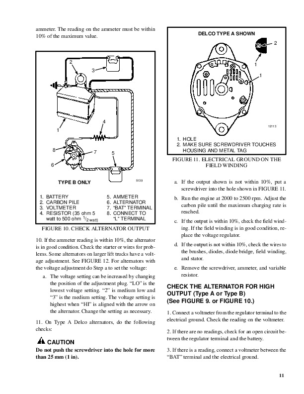
          Charging System – General…45
          Charging System – Regulator…45
          Charging System – Theory…45
        Engine Fuel System/Exhaust and Emissions…46
          Introduction…46
          Gasoline System Components – Fuel Tank…46
          Electronic Fuel Injector (EFI) – General Description…46
          Port Fuel System Components – ECU…46
          Port Fuel System Components – Fuel Pump/Filter…46
          Port Fuel System Components – Fuel Rail…46
          Port Fuel System Components – Pressure Regulator…46
          Port Fuel System Components – Fuel Injectors…47
          LPG Systems General Information…47
          LPG Fuel Properties…47
          LPG Fuel Tank…47
          AISAN Closed-Loop System…48
            Filter/Lockoff and Regulator…48
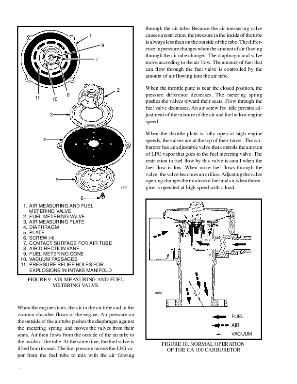
            Carburetor…48
            Start Mode…48
            Idle Mode…49
            Run Mode…49
          Main Fuel Lockoff Solenoid…49
          Injector Fuel Lockoff Solenoid…49
            Oxygen (O 2 ) Sensor…49
          Electronic Control Unit (ECU)…49
          Catalytic Converter/Muffler…49
        Engine Management…49
          Introduction…49
          Ignition and Timing – Conventional Spark…49
          Components – Ignition Coil…50
          Components – Distributor…50
          Spark Timing…50
          Components – Ignition Wires…50
          Components – Spark Plugs…50
          Faulty or Fouled Spark Plugs…51
          Electric Controlled Governing System – Mazda LPG…51
        Engine Identification…52
        Cummins (Diesel) Engine…54
          Description…54
          Diesel Fuel System…55
            Principle of Operation…55
          Fuel Injection Pump and Governor…56
            Description…56
            Principles of Operation…57
          Cummins Engine Control…58
            Engine Speed (RPM) Sensor…59
            Throttle Position Sensor…60
            Electronic Throttle Actuator…61
            Engine Oil Pressure Sensor…61
            Coolant Temperature Sensor…61
            Air Restriction Switch…62
            Fuel Filter/Water Separator…62
            Fuel Level Sensor (In Tank)…62
          Engine Electrical System…63
            Magnetic Valve (Engine Stop Solenoid)…63
            Alternator…63
            Grid Heater…63
            Cold Start Timing Advance (Fuel Injection Pump)…63
        Cummins QSB 3.3L (Diesel) Engine…64
          Description…64
          Diesel Fuel System…65
          Electronics System…68
            Engine Protection…69
            Diagnostics…69
            Grid Heater…69
          Turbocharger and Charge Air Cooler…69
          Cooling System…71
          Crankcase Oil Separator…72
          Lubrication System…73
        Mazda Engine Overview…74
          Description…74
          Fuel System…74
          Engine Controls Unit (ECU) and Emissions…74
          Cooling System…74
          Ignition System…74
        Mazda (LPG) Engine Controls…75
          LPG System (Aisan/E-Controls-Mechanical)…75
            Description…75
            Principles of Operation…76
            Control System…79
            Oxygen (O 2 ) Sensor…80
            Fuel Tank…80
            Regulator…81
              Start Mode…82
              Idle Mode…82
              Run Mode…83
            Resonator…83
            Carburetor…83
              Start Mode…83
              Idle Mode…84
              Run Mode…84
            Governor…85
          LPG System (E-Controls)…85
            Description…85
            Principles of Operation…86
            Manifold Absolute Pressure Sensor…86
            Throttle Position Sensor…86
            Oxygen (O 2 ) Sensor…87
            Engine Coolant Temperature Sensor…87
            Intake Air Temperature Sensor…87
            Engine Control Unit…87
            Accelerator Pedal Position Sensor…87
            Three-Way Catalytic Converter…87
            Camshaft Position Sensor…87
            Electric Controlled Governing System…88
            Electronic Governor Sensor…89
        Mazda (Gasoline) Engine Controls…90
          Gasoline System…90
            Description…90
            Principles of Operation…91
          Control System…93
            Camshaft Position Sensor…94
            Intake Air Temperature Sensor…95
            Mass Air Flow Sensor…96
            Throttle Position Sensor…97
            Electronic Governor Sensor…98
            Electronic Governing System…99
            Manifold Absolute Pressure Sensor/Boost Sensor…99
            Engine Coolant Temperature Sensor…100
          Intake Air System…101
            Throttle Body…101
            Idle Air Control Valve…102
          Fuel System…103
            Fuel Injector…103
            Pressure Regulator…104
          Exhaust System…105
            Heated Oxygen (O 2 ) Sensor…105
            Three-Way Catalytic Converter…106
        GM (LPG) Engine Controls…107
          Engine Control System …107
            Engine Control System Overview…108
            Principles of Operation…108
          Control System…109
            GM/TGFI 2.4L (Four Cylinder) Control System Component Location…109
            GM/TGFI 4.3L (Six Cylinder) Control System Component Location…110
            GM/TGFI 2.4L (Four-Cylinder) LPG System…111
            GM/TGFI 4.3L (Six-Cylinder) LPG System…113
            Fuel Tank…115
            Engine Control Unit…115
            Electronic Throttle Body/Throttle Position Sensor…116
            Manifold Absolute Pressure/Manifold Air Temperature Sensor…116
            Propane Injectors…117
            Engine Coolant Temperature Sensor…119
            Oxygen (O 2 ) Sensor…119
            Crankshaft Position Sensor (Engine Speed Sensor)…120
            Oil Pressure Sensor…120
            Power Latch Relay…120
            GM 2.4L Camshaft Position Sensor…120
            GM 4.3L Camshaft Position Sensor…121
            Injector Driver Module…122
            Vaporizer/Regulator…122
            Accelerator Pedal Position Sensor…125
            Three-Way Catalytic Converter…125
          Ignition System…126
            Ignition Coils…126
            Distributorless Ignition System Module…126
            Electronic Ignition Signals…127
            Distributor Ignition (DI) System…127
            Camshaft Position (CMP) Sensor…128
            Ignition Coil and Ignition Control Module (ICM)…128
            Secondary Ignition Components…128
        GM (Gasoline) Engine Controls…129
          Engine Control System…129
            GM 2.4L (Four Cylinder) Engine Control System…129
            GM 4.3L (Six Cylinder) Engine Control System…130
            Engine Control System Overview…131
            Principles of Operation…131
          Control System…131
            GM/TGFI 2.4L (Four Cylinder) Control System Component Location…131
            GM/TGFI 4.3L (Six Cylinder) Control System Component Location…133
            GM/TGFI 2.4L (Four-Cylinder) Gasoline System Components…134
            GM/TGFI 4.3L (Six Cylinder) Gasoline System Components…136
            Engine Control Unit…138
            Electronic Throttle Body/Throttle Position Sensor…138
            Manifold Absolute Pressure/Manifold Air Temperature Sensor …139
            Fuel Injector…140
            Engine Coolant Temperature Sensor…141
            Oxygen (O 2 ) Sensor…142
            Crankshaft Position Sensor (Engine Speed Sensor)…142
            Oil Pressure Sensor…142
            Power Latch Relay…142
            Camshaft Position Sensor…143
            Accelerator Pedal Position Sensor…144
            Three-Way Catalytic Converter…145
          Ignition System…145
            Ignition Coils…145
            Distributorless Ignition System Module…145
            Electronic Ignition Signals…146
        Yanmar (Diesel) Engine…147
          Description…147
          Diesel Fuel System…148
            Principles of Operation…148
          Fuel Injection Pump and Governor…149
            Description…149
            Principles of Operation…151
            Timer…152
            Feed Pump (Vane Type)…152
            Regulating Valve…153
            Injection Pump Plunger…154
              Suction Process…155
              Injection Process…155
              End of Injection…156
              Uniform Pressure Process…156
            Reverse Rotation Prevention Mechanism…157
            Fuel Injection Volume Adjustment Mechanism…157
            Delivery Valve Assembly…157
            Delivery Valve Holder with Damping Valve…158
            All – Speed Governor…159
            At Start of Engine…161
            During Idle…162
            At Full – Load Maximum Speed Control…163
            At No-Load Maximum Speed Control…164
            Full-Load Position Adjustment Mechanism…165
          Structure and Operation of Timer…166
            Standard Type Automatic Timer…166
          Yanmar Engine Controls…167
            Engine Speed (RPM) Sensor…168
            Throttle Position Sensor…168
            Electronic Throttle Actuator…169
            Engine Oil Pressure Sensor…169
            Coolant Temperature Sensor…170
            Air Filter Restriction Switch…170
            Fuel Filter/Water Separator and Strainer…171
            Fuel Level Sensor…171
          Engine Electrical System…171
            Magnetic Valve (Engine Stop Solenoid)…171
            Alternator…172
            Glow Plugs…172
            Cold Start Timing Advance (Fuel Injection Pump)…172
        Cooling System – All Engines…173
          Description…173
          Radiator…173
            Combination Cooler/Standard Radiator…174
          Radiator Cap…174
          Thermostat…174
          Engine Coolant Pump…175
          Fan…175
          GM Engine Coolant Flow Diagram…175
          Yanmar Diesel Engine Coolant Flow Diagram…176
        Engine Does Not Crank…178
        Engine Does Not Start/Engine is Hard to Start…181
        Engine Idle Speed Incorrect…187
        Engine Idle Speed is Unstable or Engine Stalls at Idle…190
        Engine Cuts Out, Misses, Hesitates, Sags, or Stumbles…195
        Engine Lack of Power…201
        Engine Speed Surge Or Engine Speed Unstable…208
        Engine Backfires…212
        Engine Is Knocking or Pinging…215
        Excessive Engine Vibrations…219
        Abnormal Engine and Exhaust Noises…224
        Fan or Alternator Bearing Noise…228
        Abnormal Engine and Exhaust Smells…230
        High Engine Fuel Consumption…232
        Fuel Leaks…235
        High Engine Oil Consumption…238
        Engine Oil Leaks…240
        Engine Oil is Discolored…245
        Engine Coolant Leaks…247
        Engine Coolant is Discolored…250
        Engine Exhaust is Discolored…251
        Engine Fails Emission Compliance Check…255
        Alternator Light is Illuminated…259
        Engine is Overheating…260
        Air Intake Manifold Temperature too High (Cummins QSB 3.3L Only)…263
        Air Intake Manifold Pressure (Boost) is Below Normal (Cummins QS…264
        Engine Coolant Temperature is Low…265
        Engine Oil Pressure is Low…266
        Radiator Bubble Test…268
        Engine Compression Test (GM and Mazda)…269
        Engine Compression Test (Yanmar Diesel)…270
        Engine Oil Pressure Test…271
        Fuel System Pressure Test (Gasoline Engines Only)…273
        Fuel Injection Nozzle Test (Yanmar Diesel)…275
        Vacuum Leak…276
          Vacuum Leak Detection…276
          Vacuum Leak Repairs…276
        Coolant System Test…277
      Electrical System…278
        Troubleshooting Guidelines and Procedures…292
          Troubleshooting Guidelines…292
          Troubleshooting Procedures…295
            Troubleshooting Procedures, Identification…295
            Troubleshooting Procedures, Location…295
            Troubleshooting Procedures, Structure…295
            Troubleshooting Procedures, Performance…296
        Diagnostic Trouble Codes…297
          Diagnostic Trouble Codes…297
        Wiring Reference Data…311
        Post 2007 Engine Connections…315
          Cummins 4.5L…315
          GM 2.4L (GAS/LPG)…316
          GM 4.3L (GAS/LPG)…317
          Mazda 2.0/2.2L (GAS/LPG)…318
          Yanmar 2.6/3.3L…319
        Harness Assembly Data…320
        Electrical System…366
          General Description…366
          Description…367
          Principles of Operation, Components…371
          Principles Of Operation, System…379
        100-2…386
        100-2…386
        100-3…386
        523859-3…386
        524223-3…386
        524224-3…386
        524225-3…386
        524282-3…386
        523958-3…386
        523959-3…386
        100-4…394
        523859-4…394
        523958-4…394
        523959-4…394
        524223-4…394
        524224-4…394
        524225-4…394
        524282-4…394
        524223-0…402
        524224-0…402
        524225-0…402
        524229-0…402
        524270-0…402
        524276-0…402
        524223-1…406
        524224-1…406
        524225-1…406
        524229-1…406
        524270-1…406
        524276-1…406
        110-3…410
        110-3…410
        110-5…410
        177-3…410
        522231-3…410
        522555-3…410
        522603-3…410
        524235-3…410
        110-4…418
        110-4…418
        177-4…418
        522231-4…418
        522555-4…418
        522603-4…418
        524235-4…418
        110-2…426
        110-2…426
        110-10…429
        522712-3…434
        522713-3…434
        522712-4…441
        522713-4…441
        51-2…448
        51-7…448
        91-2…456
        91-2…456
        522708-3…460
        522710-3…460
        522711-3…460
        522714-3…460
        522708-4…467
        522710-4…467
        522711-4…467
        522714-4…467
        515-0…474
        523780-3…476
        523860-3…476
        524245-3…476
        524275-3…476
        523780-4…482
        523860-4…482
        524245-4…482
        524275-4…482
        677-3…487
        2350-3…487
        522754-3…487
        522755-3…487
        522764-3…487
        522766-3…487
        524230-3…487
        SYMPTOMS WARNING…487
        677-4…493
        2350-4…493
        522754-4…493
        522755-4…493
        522764-4…493
        522766-4…493
        524230-4…493
        676-3…497
        524195-3…497
        524269-3…497
        676-4…503
        524195-4…503
        524269-4…503
        524269-7…509
        524215-3…511
        524215-6…511
        524237-3…515
        524238-3…515
        524240-3…515
        524237-4…520
        524238-4…520
        524240-4…520
        879-3…525
        880-3…525
        881-3…525
        882-3…525
        522772-3…525
        879-4…529
        880-4…529
        881-4…529
        882-4…529
        522772-4…529
        168-0…533
        168-3…533
        521982-3…536
        522760-3…536
        522761-3…536
        522762-3…536
        522128-3…545
        524251-0…545
        524260-0…545
        524260-3…545
        524261-0…545
        524261-3…545
        168-1…554
        168-4…554
        521982-4…557
        522760-4…557
        522761-4…557
        522761-6…557
        522762-4…557
        522128-4…564
        524251-1…564
        524260-1…564
        524260-4…564
        524261-1…564
        524261-4…564
        524260-2…574
        524260-11…574
        524261-2…574
        524261-11…574
        96-3…578
        96-4…578
        522810-4…582
        524213-1…586
        524213-3…586
        524213-4…586
        523920-3…589
        523925-3…589
        523930-3…589
        523977-3…589
        523978-3…589
        523986-3…589
        524284-3…589
        524285-3…589
        523920-4…595
        523925-4…595
        523930-4…595
        523977-4…595
        523978-4…595
        523986-4…595
        524284-4…595
        524285-4…595
        523920-6…600
        523925-6…600
        523930-6…600
        523977-6…600
        523978-6…600
        523986-6…600
        524284-6…600
        524285-6…600
        105-3…604
        105-3…604
        522570-3…604
        105-4…609
        105-4…609
        522570-4…609
        105-5…613
        106-3…616
        106-4…620
        106-0…624
        106-1…624
        106-2…624
        106-14…624
        522739-3…627
        522740-3…627
        522739-5…632
        522740-5…632
        522739-6…636
        522740-6…636
        522735-2…640
        522735-4…643
        522735-5…646
        522735-6…649
        522630-2…653
        522631-2…653
        522632-2…653
        522633-2…653
        522635-3…653
        522636-4…653
        522637-3…653
        522638-4…653
        522606-10…657
        522737-10…657
        651-3…660
        652-3…660
        653-3…660
        654-3…660
        655-3…660
        656-3…660
        522599-3…660
        522600-3…660
        522601-3…660
        522602-3…660
        522721-3…660
        522722-3…660
        522723-3…660
        522724-3…660
        522725-3…660
        522726-3…660
        522599-3…660
        522600-3…660
        522601-3…660
        522602-3…660
        651-5…668
        651-5…668
        652-5…668
        652-5…668
        653-5…668
        653-5…668
        654-5…668
        654-5…668
        655-5…668
        656-5…668
        522721-5…668
        522722-5…668
        522723-5…668
        522724-5…668
        522725-5…668
        522726-5…668
        651-6…673
        652-6…673
        653-6…673
        654-6…673
        655-6…673
        656-6…673
        522599-4…673
        522600-4…673
        522601-4…673
        522602-4…673
        522721-6…673
        522722-6…673
        522723-6…673
        522724-6…673
        522725-6…673
        522726-6…673
        2000-9…681
        2000-12…681
        2000-12…681
        2000-12…681
        2000-12…681
        2000-14…681
        2003-12…681
        2023-12…681
        2039-2…681
        2039-12…681
        2235-12…681
        2236-12…681
        2238-12…681
        521670-12…681
        524258-2…681
        522215-12…689
        522215-14…689
        524236-14…689
        524262-12…689
        524262-14…689
        524263-1…689
        524268-12…689
        628-12…691
        630-12…691
        522690-2…691
        522690-12…691
        522691-2…691
        522691-12…691
        522692-2…691
        522693-12…691
        522694-12…691
        522695-2…691
        522696-2…691
        522697-12…691
        522698-2…691
        522699-2…691
        522700-2…691
        190-2…693
        190-2…693
        190-7…693
        522120-1…693
        522585-2…693
        522752-9…699
        524249-2…703
        524250-2…703
        524264-2…703
        524264-14…703
        524265-2…703
        524271-2…703
        524225-14…703
        628-12…708
        630-12…708
        2660-3…708
        2660-4…708
        2661-3…708
        2661-4…708
        2802-12…708
        523510-12…708
        523511-12…708
        523515-3…708
        523515-4…708
        523519-3…708
        523519-4…708
        2802-12…710
        628-12…710
        630-12…710
        523261-3…710
        523261-4…710
        523257-3…710
        523257-4…710
        523253-3…710
        523253-4…710
        523249-3…710
        523249-4…710
        522780-3…712
        522781-3…712
        522780-4…716
        522781-4…716
        522780-2…719
        522781-2…719
        111-1…722
        524252-2…726
        524253-14…728
        524255-2…729
        108-0…730
        108-1…730
        522655-0…733
        522655-1…733
        522660-0…733
        522660-1…733
        524212-2…737
        524211-2…737
        524210-2…737
        524209-2…737
        524208-2…737
        524207-2…737
        524206-2…737
        524205-2…737
        524204-2…737
        524203-2…737
        524202-2…737
        524201-2…737
        524200-2…737
        524199-2…737
        524198-2…737
        524197-2…737
        522800-13…739
        522801-13…741
        522130-0…742
        522131-0…742
        522132-0…742
        522133-0…742
        522134-0…742
        522130-1…746
        522131-1…746
        522132-1…746
        522133-1…746
        522134-1…746
        522130-3…751
        522131-3…751
        522132-3…751
        522133-3…751
        522134-3…751
        522130-4…756
        522131-4…756
        522132-4…756
        522133-4…756
        522134-4…756
        522135-0…760
        522137-0…760
        522138-0…760
        522135-1…764
        522137-1…764
        522138-1…764
        522135-3…768
        522137-3…768
        522138-3…768
        522135-4…772
        522137-4…772
        522138-4…772
        522155-2…776
        522157-2…776
        522122-0…783
        522124-0…783
        522125-0…783
        522126-0…783
        522127-0…783
        522122-1…787
        522124-1…787
        522125-1…787
        522126-1…787
        522127-1…787
        522122-6…791
        522124-6…791
        522125-6…791
        522126-6…791
        522127-6…791
        522122-8…796
        522124-8…796
        522125-8…796
        522126-8…796
        522127-8…796
        522129-3…800
        522129-4…800
        522197-0…802
        522198-0…802
        522199-0…802
        522200-0…802
        522201-0…802
        522197-1…805
        522198-1…805
        522199-1…805
        522200-1…805
        522201-1…805
        522197-6…806
        522198-6…806
        522199-6…806
        522200-6…806
        522201-6…806
        522197-7…807
        522198-7…807
        522199-7…807
        522200-7…807
        522201-7…807
        522197-8…808
        522198-8…808
        522199-8…808
        522200-8…808
        522201-8…808
        522197-14…810
        522198-14…810
        522199-14…810
        522200-14…810
        522201-14…810
        522197-27…811
        522198-27…811
        522199-27…811
        522200-27…811
        522201-27…811
        2039-2…814
        522540-3…817
        522540-4…821
        522604-3…826
        522604-4…830
        522604-5…834
        522697-12…839
        190-2…840
        190-4…840
        190-8…840
        522752-2…840
        522752-4…840
        522752-5…846
        522598-3…849
        522598-4…853
        522592-0…857
        522592-1…859
        522593-12…861
        522594-12…865
        522595-12…865
        522596-12…865
        522597-12…865
        522614-7…868
        522616-8…868
        522617-5…868
        524226-3…869
        524226-4…871
        524239…873
        524241…873
        524246…873
        524267…873
        524248…873
        524746-2…876
        Engine Continues to Run When Engine Cover is Raised…878
        Engine Stops or Fails to Start…880
        Electrical Functions Do Not Operate…882
        Electrical Function Does Not Turn Off…887
        Electro-Hydraulics Do Not Function With Armrest Down …893
        Electro-Hydraulics Can Still Function With Armrest Raised…896
        Vehicle Does Not Power On…899
        Heater Fan Does Not Operate Properly…904
        Heater Airflow Does Not Reach Desired Temperature…907
        Heater Output Has Insufficient Airflow…908
        Circulating (Accessory) Fan Inoperative…909
        Dome Light Inoperative…912
        Horn Failure…915
      Drive Train…918
        Mechanical Overview…922
        Engine…922
          Description…922
        Torque Converter…922
          Description…922
            Stator…923
            Turbine…923
        Pump PTO…924
          Chain Drive PTO…924
          Spur Gear PTO…925
        Transmission…926
          Description…926
          1.0-5.5 Ton Lift Truck Transmissions…929
            Description…929
              Single-Speed…929
              Two-Speed…930
            Clutch Pack…931
            Power Flow…933
              Single-Speed…933
              Two-Speed…934
            Transmission Hydraulic Schematic…936
            Transmission Oil Flow…937
            Control Valve Oil Flow…937
          6.0-7.0 Ton Lift Truck Transmissions…939
            Description…939
              Two-Speed…939
              Three-Speed…939
            Clutch Pack…941
              Input Shaft and Range Clutches…941
              Directional Clutches…941
              Output Section…942
            Power Flow…943
              Two-Speed and Three-Speed…943
            Transmission Hydraulic Schematic…947
              Two-Speed…947
              Three-Speed…948
        Transmission Control System Overview…950
          Transmission Control System…950
        Transmission Control Software…953
          Transmission Control Modes…953
            Neutral…953
            Gear Engagement Control…953
              Basic Powershift Gear Engagement Mode…953
              DuraMatch™ and Electronic Extended Features Gear Engagement Mo…953
            Normal Forward or Reverse…953
              Basic Powershift…953
              DuraMatch™ and Electronic Extended Features Transmission…953
            Auto-Shift…953
            1st Gear Lock…954
            Inching…954
              Basic Powershift Inching Mode…954
              DuraMatch™ Inching Mode…954
              Electronic Extended Features Inching Mode…954
            Inch/Brake Overlap Adjustment…954
            Brake Wear Compensation…954
            Auto Decel…955
            Controlled Power Reversal…955
              Basic Multi-Speed…955
              Electronic Extended Features…955
            Controlled Creep…955
              Basic Powershift…955
              DuraMatch™ and Electronic Extended Features…956
            Controlled Roll Back…956
              DuraMatch™ …956
              Electronic Extended Features…956
            Travel Speed Limit (Optional)…956
            Extended Drawbar Pull ( Electronic Extended Features Multi-Speed…956
            Auto-Speed Hydraulics ( Electronic Extended Features Transmissio…956
            Throttle Response Management ( Electronic Extended Features Tran…957
              Steady Travel Speed…957
        Transmission Control Hardware…957
          Control Valve and Sensors…957
            Description…957
            Principles of Operation…959
          Transmission Proportional Valve…960
            Description…960
            Neutral…960
            Proportional Control…960
          MONOTROL® Pedal…961
            Description…961
            Principles of Operation…961
          Directional Control Lever…961
            Principles of Operation…961
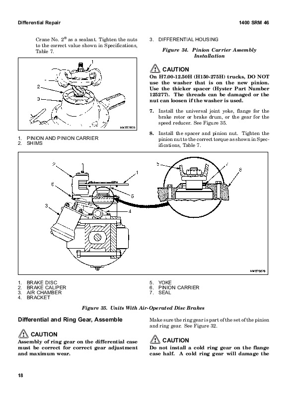
        Driveshaft, Differential, Drive Axle, and Brakes (Dry Brake Only…962
          Driveshaft…962
          Differential and Drive Axle…962
          Brake System…964
            Description…964
            Service Brakes…964
            Master Cylinder…964
            Brake Position Sensor…965
            Parking Brake…965
        Driveshaft, Differential, Drive Axle, and Brakes (Wet Brake Only…965
          Driveshaft…965
          Differential…966
          Brake System…968
            Description…968
            Service Brakes, 2.0-3.5 Ton Only…968
            Service Brakes, 4.0-7.0 Ton…970
            Brake Adjustment and Service…970
            Parking Brake…970
        Overheating Brakes (Dry Brake Axle Only)…974
        Overheating Brakes (Wet Brake Axle Only)…976
        Poor Brake Performance (Dry Brake Axle Only)…979
        Poor Brake Performance (Wet Brake Axle Only)…982
        Brakes Make Too Much Noise (Dry Brake Axle Only)…984
        Brakes Pull To One Side (Dry Brake Axle Only)…985
        Parking Brake Will Not Release…988
        Parking Brake Will Not Hold Lift Truck (Dry Brake Axle Only)…989
        Parking Brake Will Not Hold Lift Truck (Wet Brake Axle Only)…990
        Abnormal Drive Axle Noise…991
        Discolored Drive Axle Oil…994
        Lift Truck Does Not Move (Drive Axle)…996
        Abnormal Transmission Noise…999
        Bubbles or Foaming In Transmission Dipstick Tube…1001
        Inching Operation Is Not Smooth or Chatters…1003
        Lift Truck Does Not Move In One or Both Directions (Transmission…1005
        Loss of Power/Drivetrain Performance…1008
        Transmission Is Too Hot…1011
        Transmission Will Not Shift To Forward High Range…1014
        Transmission Warmup Procedure…1016
        Transmission Pressure Test…1016
          Transmission Charge Pump Pressure Test…1018
          Clutch Pack Pressure Test (Proportional Solenoid Valves)…1018
          Torque Converter Pressure Test…1019
          Lubrication Pressure Test…1019
        Transmission Clutch Drag Test (1.0-5.5 Ton Trucks Only)…1020
        Torque Converter Stall Test…1020
      Hydraulic Systems…1024
        Main Hydraulic System…1028
          Description…1028
          Principles of Operation…1031
          Hydraulic Schematics…1032
            Manual Control Valve Schematics…1032
            Electro-Hydraulic Control Valve Schematics…1037
        Manual Hydraulic Control Valve…1041
          Description…1041
          Principles of Operation…1043
            Lift Section…1043
              Lift Operation…1043
              Lower Operation…1043
            Tilt Section…1044
              Tilt Backward…1044
              Tilt Forward…1044
            Auxiliary Section…1046
            Anti-stall Feature…1047
            Relief Valves…1047
              Main Relief Valve…1047
              Secondary Relief Valve…1047
        Electro-Hydraulic Control Valve…1048
          Description…1048
          Principles of Operation…1049
            Inlet Pressure Compensator/Unloader…1049
            Lift/Lower EHPVs…1051
              EHPV Operation…1052
            Tilt and Auxiliary Spool Functions…1053
            Tilt Forward Function…1055
            Main Relief Valve …1056
            Secondary Relief Valve…1056
            Secondary Function Anti-stall Valve…1057
            Emergency Lowering Valve…1058
        Steering System…1058
          Component Locations…1058
            Description…1058
            Steering Axle Assembly…1058
            Steering Control Unit…1058
          Steering Schematic…1060
            Principles of Operation…1061
            Steering Control Unit…1061
        Actuation Functions With Armrest Up (E-Valve)…1062
        Cycle Times Too Fast – Fast Actuation (E-Valve)…1063
        Jump/Delay In Lift or Lower Activation After Moving Joystick or …1065
        Jump/Delay In Secondary Function Actuation After Moving Joystick…1068
        Jump/Delay In Tilt Forward Actuation (E-Valve)…1070
        Forks Drop Slightly Before Lifting (E-Valve)…1072
        Forks Lower Without Command (E-Valve)…1073
        Forks Raise or Actuate Without Command (E-Valve)…1075
        Forks Tilt Forward Without Command (E-Valve)…1077
        Intermittent Activation (E-Valve) While Commanding Function…1079
        Lift/Lower Function Maximum Speed Too Slow (E-Valve)…1081
        Lift Function Will Not Move With Joystick or MLM Movement (E-Val…1084
        Lift/Lower Continues To Move For Awhile After Joystick or MLM Is…1088
        Lift/Lower/Secondary Function Suddenly Jumps In Middle of Stroke…1089
        Lower Function Will Not Move With Joystick or MLM Movement (E-Va…1090
        Poor Metering on Lift or Lower Functions (E-Valve)…1092
        Secondary Function Continues to Move for Awhile After Joystick o…1095
        Secondary Function Exhibits Slight Movement in Opposite Directio…1096
        Secondary Function Maximum Speed Too Slow (E-Valve)…1097
        Secondary Function or Tilt Back Moves Without Command (E-Valve)…1100
        Secondary Function and Tilt Back Will Not Move With Joystick or …1102
        Tilt Forward Function Continues to Move for Awhile When Joystick…1106
        Tilt Forward Will Not Move Upon Joystick or MLM Movement (E-Valv…1107
        Too Much Joystick or MLM Movement (Deadband) to Start Function M…1109
        Wrong Actuation Operates or Actuation is Backward (E-Valve)…1110
        Actuation Exhibits Slight Movement in Opposite Direction Before …1111
        Auxiliary Function is Slow or Does Not Function (Manual Valve)…1112
        Cycle Times Too Fast – Fast Actuation (Manual Valve)…1114
        Function Continues to Activate After Returning to Neutral…1115
        Lift Function Is Slow or Does Not Function (Manual Valve)…1116
        Tilt Back Function Will Not Operate (Manual Valve)…1118
        Tilt Forward Functions When Spool is Activated Forward With Engi…1119
        Tilt Forward Will Not Function When Activated (Manual Valve)…1120
        Abnormal Steer Axle Noise…1121
        Abnormal Steering Wheel Vibration…1123
        Back Lash/Kick Back in Steering Wheel…1124
        No Steering (All Other Hydraulic Functions OK)…1126
        Steering Is Slow or Difficult…1128
        Steering Operation Is Not Smooth…1130
        Steering Wheel End Lock Position Cannot Be Felt by Operator…1132
        Steering Wheel Turns By Itself or Does Not Return To Neutral…1133
        Steering Wheel Turns the Tires in the Wrong Direction…1134
        Abnormal Hydraulic Noise and/or Vibration…1135
        Abnormal Smell/Discoloration/Foaming of Oil…1138
        Actuations Do Not Act Simultaneously…1139
        Oil Leaking/Component Life Too Short…1140
        Hydraulic Warmup Procedure…1144
        Main Relief Valve Test and Adjustment…1145
        Secondary Relief Valve Test and Adjustment…1147
        Hydraulic Pump Flow Test…1149
        Main Control Valve LS Leakage Test (E-Valve)…1151
        Main Control Valve Unloader Margin Test…1152
        Electro-Hydraulic Poppet Valve (EHPV) Leakage Test…1153
        PPRV Pilot Pressure Test…1156
        Steering Relief Pressure Test and Adjustment…1157
        Steering Control Unit LS Pressure Test…1158
        Lift Cylinder Leakage Test…1160
        Tilt Cylinder Leakage Test…1161
        Steering Cylinder Leakage Test…1162
      Operators Station…1164
        Operator Station General Description and Principles of Operation…1166
          General Description and Location…1166
        Display Switch Cluster (DSC)…1168
          Detailed Description…1168
          Control Inputs, Right Side…1169
          Right Indicator and Warning Group…1171
          LCD Display…1172
          Left Indicator and Warning Group…1173
          Control Inputs, Left Side (Cab Option Only)…1174
        Transmission Control and Braking…1175
          Description…1175
            Vehicle System Manager (VSM)…1176
            Display Switch Cluster…1176
              Interlock and Switching Features…1176
            MONOTROL® Directional Control…1176
            Inch Brake/Service Brake Pedal…1176
            Parking Brake…1177
        Programming – Menus…1177
          Menus…1177
            Main Menu…1180
            Save and Exit or Exit Without Saving…1180
            Back One Level…1180
            Hourmeters…1180
            View Versions…1181
            Passwords…1181
            Diagnostics…1181
            Setup Travel and Braking…1181
            Setup Hydraulics…1181
            Setup Display…1181
            Setup General Items…1181
            Calibrations…1181
        Manual Hydraulic Control Levers…1182
          General Description…1182
          System Components…1182
            Lift/Lower…1182
            Tilt…1182
            Auxiliary 1…1182
            Auxiliary 2…1182
        E-Hydraulic System Interface…1183
          General Description…1183
          System Components…1183
          E-Hydraulic Control Input Device…1183
            Joystick…1183
              Lift/Lower…1184
              Tilt…1184
              Auxiliary 1…1184
              Auxiliary 2…1184
              Push Button…1184
            Mini Lever Module (MLM)…1185
              Lever 1…1185
              Lever 2…1185
              Lever 3…1186
              Lever 4…1186
          System Modes…1186
            Hydraulic Interlock Mode…1186
            Fault Mode…1186
            Engine Off Mode…1186
          Normal Operation…1186
            Normal Operation Mode…1186
            Lifting Control…1186
            Lowering Control…1187
            Tilt Control (Forward and Backward)…1187
            Auxiliary Control…1187
        Lighting Control…1187
          Description…1187
            Front Work Lights…1190
            Front Marker Lights (if equipped)…1190
            Front/Rear Turn Signal Lights…1190
            Rear Tail/Marker Lights…1190
            Rear Work Light…1190
            Rear Backup Lights…1190
            Rear Stop Lights…1190
            Strobe Light(s)…1190
            Spot Light (if equipped)…1190
        Cab…1190
          Description…1190
          Component Descriptions…1192
            Cab Heating System…1192
            Lighting Control System…1192
            Wiper/Washer System…1192
          Cab Systems Operation…1193
      Front End (Mast) and Chassis…1196
        Front End, Mast…1198
          Description…1198
        Carriages…1198
          Description…1198
          Principles of Operation…1199
            Integral Sideshift Carriage…1199
        Mast Mounts…1201
          Description…1201
          Principles of Operation…1201
        Two-Stage Limited Free-Lift (LFL) Mast…1203
          Description…1203
          Principles of Operation…1204
        Two-Stage Full Free-Lift (FFL) Mast…1205
          Description…1205
          Principles of Operation…1206
        Three-Stage Full Free-Lift (FFL) Mast…1207
          Description…1207
          Principles of Operation…1207
        Four-Stage Full Free-Lift (FFL) Mast…1209
          Description…1209
          Principles of Operation…1210
        Cylinder Cushion During Lifting Sequence…1212
          Description…1212
          Principles of Operation…1212
        Cylinder Cushion During Lowering Sequence…1213
          Description…1213
          Principles of Operation…1213
        Tilt and Sideshift Cylinders…1213
          Description…1213
            Tilt Cylinder…1213
            Sideshift Cylinder…1213
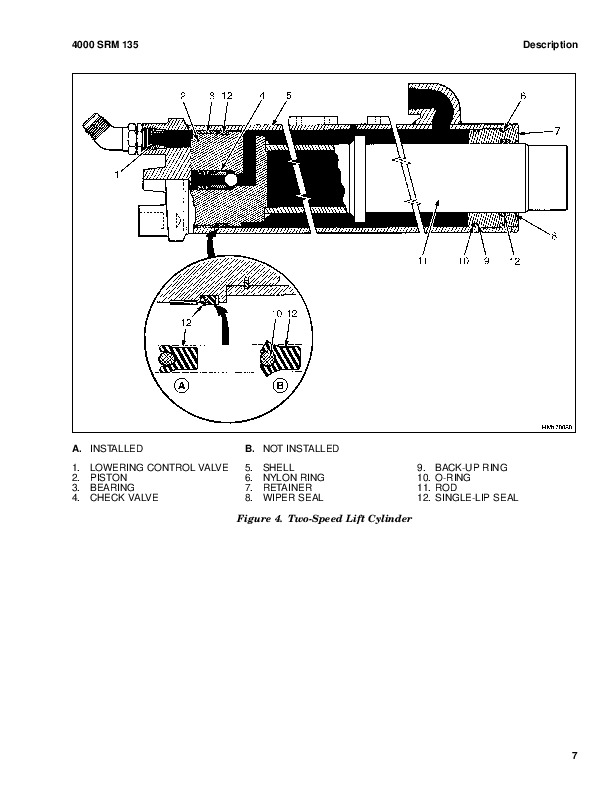
        Lowering Control Valves…1214
          Description…1214
          Principles of Operation…1214
        Chassis…1216
          Description…1216
        Abnormal Channel Wear…1218
        Abnormal Hose Wear…1220
        Abnormal Mast Noise…1222
        Body Panels Making Noise…1226
        External Leakage From Free-Lift or Main Lift Cylinders…1227
        FFL Mast Banging During Phasing…1228
        High Tire Wear – Drive Axle…1230
        High Tire Wear – Steer Axle…1232
        Hoses Not Tracking Correctly…1234
        Integral Sideshift Moving Too Fast…1235
        Integral Sideshift Not Moving or Slow…1236
        LP Tank Bracket Disengages…1239
        LP Tank Rattles and Does Not Stay Latched…1240
        Mast is Loose…1241
        Mast Lift Chains Are Loose…1243
        Mast or Carriage Binding…1244
        Mast/Carriage Bounces or is Spongy…1246
        Misphasing of Full Free-Lift Mast…1247
        Overhead Guard Loose or Damaged…1249
        Racking During Lift…1250
        Racking During Tilt…1252
        Truck Feels Unstable…1253
        Truck Wanders, Does Not Track Straight or Steer Well…1255
        Wheels Appear Tipped or Misaligned…1257
        Wheels Spinning On Uneven Floors…1259
        Wheel Studs Breaking…1260
      Supplementary Data…1262
        Abbreviations and Acronyms…1264
        Special Tools List…1272
        Fault Mode Indicator (FMI) Reference List…1278
        TSP Reference Tables…1280
    tables…4
      Table 9020-10-1. IAT Ambient Temperature…95
      Table 9020-40-1. Test Specifications…268
      Table 9020-40-2. Test Specifications…269
      Table 9020-40-3. Service Tools…269
      Table 9020-40-4. Test Specifications…270
      Table 9020-40-5. Service Tools…270
      Table 9020-40-6. Test Specifications…271
      Table 9020-40-7. Service Tools…272
      Table 9020-40-8. Test Specifications – Mazda…273
      Table 9020-40-9. Test Specifications – GM…273
      Table 9020-40-10. Service Tools…273
      Table 9020-40-11. Test Specifications…275
      Table 9020-40-12. Service Tools…275
      Table 9020-40-13. Test Specifications…277
      Table 9020-40-14. Service Tools…277
      Table 9030-03-1. Cummins QSB 3.3L Fault Codes…308
      Table 9030-03-2. Circuit Group Identification…311
      Table 9030-03-3. Hyster Wiring Color Codes…312
      Table 9040-10-1. Two-Speed Transmission Clutch Pack Solenoid Val…948
      Table 9040-10-2. Three-Speed Transmission Electronic Proportiona…949
      Table 9040-10-3. Transmission Control Mode…951
      Table 9040-40-1. Test Specifications…1016
      Table 9040-40-2. Service Tools…1016
      Table 9040-40-3. Service Tools…1016
      Table 9040-40-4. Test Specifications…1018
      Table 9040-40-5. Test Specifications…1018
      Table 9040-40-6. Test Specifications…1019
      Table 9040-40-7. Test Specifications…1019
      Table 9040-40-8. Test Specifications…1020
      Table 9040-40-9. Service Tools…1020
      Table 9040-40-10. Stall Speeds…1021
      Table 9050-10-1. Standby Pressure Table…1050
      Table 9050-40-1. Test Specifications…1144
      Table 9050-40-2. Service Tools…1144
      Table 9050-40-3. Test Specifications…1145
      Table 9050-40-4. Service Tools…1145
      Table 9050-40-5. Test Specifications…1147
      Table 9050-40-6. Service Tools…1147
      Table 9050-40-7. Test Specifications…1149
      Table 9050-40-8. Service Tools…1150
      Table 9050-40-9. Test Specifications…1151
      Table 9050-40-10. Test Specifications…1152
      Table 9050-40-11. Service Tools…1152
      Table 9050-40-12. Test Specifications…1153
      Table 9050-40-13. Service Tools…1153
      Table 9050-40-14. Test Specifications…1156
      Table 9050-40-15. Service Tools…1156
      Table 9050-40-16. Test Specifications…1157
      Table 9050-40-17. Service Tools…1157
      Table 9050-40-18. Test Specifications…1158
      Table 9050-40-19. Service Tools…1159
      Table 9050-40-20. Test Specifications…1160
      Table 9050-40-21. Service Tools…1160
      Table 9050-40-22. Test Specifications…1161
      Table 9050-40-23. Service Tools…1161
      Table 9050-40-24. Test Specifications…1162
      Table 9050-40-25. Service Tools…1162
      Table 9080-50-1. Abbreviations and Acronyms…1264
      Table 9080-60-1. Special Tools…1272
      Table 9080-70-1. FMI…1278
      Table 9080-80-1. Resistor-Temperature Characteristics …1280
  1580502-0100SRM1120-(01-2007)-UK-EN…1284
    toc…1284
      Frame…1284
      Safety Precautions Maintenance and Repair…1285
      General…1288
      Description…1289
      Hood, Seat, and Side Covers Replacement…1289
        Remove…1289
        Install…1294
      LPG Tank and Bracket Replacement…1296
        Remove…1296
          LPG Tank…1296
          LPG Bracket…1299
        Install…1299
          LPG Bracket…1299
          LPG Tank…1300
      Counterweight Replacement…1301
        Remove…1301
        Install…1302
        Tow Pin, Remove and Install…1303
      Overhead Guard Replacement…1303
        Remove and Install…1303
        LED Tail, Backup, and Brake Lights, Replace…1304
      Operator Restraint System Replacement…1305
        Description…1305
          Automatic Locking Retractor (ALR)…1305
          Emergency Locking Retractor (ELR)…1305
      Engine Replacement…1306
        Remove Engine Only…1306
        Remove Engine and Transmission…1310
        Install Engine Only…1310
        Install Engine and Transmission…1311
      Throttle Pedal and Cable Adjustment…1312
        Mazda Gas/LPG Engines With Basic Power Shift Transmission and Ma…1312
        Mazda Gasoline Engine With Electronic Transmission…1315
        Throttle Pedal Stop Adjustment, Mazda 2007 Emission Compliant En…1316
        Yanmar Diesel Engine With Basic Power Shift Transmission…1316
        Yanmar Diesel Engine With Electronic Throttle…1316
      Exhaust System Repair…1318
        Lift Trucks With Counterweight Exhaust System…1318
          Mazda and GM Gas and LPG Engines…1318
            Remove and Disassemble…1318
            Inspect…1318
            Assemble and Install…1320
          Yanmar Diesel Engine…1322
            Remove and Disassemble…1322
            Inspect…1322
            Assemble and Install…1322
        Lift Trucks With Overhead Exhaust System…1324
          Yanmar Diesel Engine…1324
            Remove and Disassemble…1324
            Inspect…1324
            Assemble and Install…1325
          Mazda Gas and LPG Engines…1327
            Remove and Disassemble…1327
            Inspect…1327
            Assemble and Install…1327
      Cooling System…1331
        Description…1331
      Fuel and Hydraulic Tanks Repair…1331
        Inspect…1331
        Clean…1331
          Steam Method of Cleaning…1331
          Chemical Solution Method of Cleaning…1332
        Additional Preparations for Repair…1332
        Small Leaks, Repair…1333
        Large Leaks, Repair…1333
        Preparations for Use After Repair…1333
      Safety Labels…1333
    tables…1284
      Table 1. Weight of Counterweights, Lift Truck Models S2.0-3.5FT …1302
      Table 2. Weight of Counterweights, Lift Truck Models S30FT, S35F…1302
      Table 3. Weight of Counterweights, Lift Truck Models H1.6FT, H1…1302
      Table 4. Weight of Counterweights, Lift Truck Models H2.0-3.5FT …1302
  1580504-0600SRM1122-(12-2006)-UK-EN…1338
    toc…1338
      Mazda Engine…1338
      Safety Precautions Maintenance and Repair…1339
      General…1342
        Serial Number…1342
      Engine Removal and Installation…1342
      Cylinder Head, Camshaft, and Valve Mechanism Repair…1343
        Remove…1343
        Clean…1345
        Inspect and Repair…1345
          Cylinder Head…1345
          Rocker Shaft Assembly…1345
          Camshaft…1345
          Valve Guides…1347
          Valve Seats…1347
          Valves…1347
          Valve Springs…1348
        Install…1348
      Crankshaft and Main Bearings Repair…1352
        Remove…1352
        Inspect and Repair…1353
          Crankshaft…1353
          Main Bearings…1353
        Install…1354
      Pistons and Connecting Rods Repair…1355
        Remove and Disassemble…1355
        Clean…1355
        Inspect and Repair…1355
          Pistons…1355
          Piston Rings…1355
          Connecting Rods and Bearings…1356
        Assemble and Install…1356
      Cylinder Block Repair…1358
      Oil Pump Repair…1358
        Remove…1358
        Disassemble…1360
        Clean…1360
        Inspect…1360
        Assemble…1361
        Install…1361
      Cooling System Repair…1363
        Thermostat…1363
          Replace…1363
        Fan Assembly…1363
          Remove and Disassemble…1363
          Assemble and Install…1363
        Water Pump…1364
          Remove…1364
          Install…1365
      Flywheel and Ring Gear Repair…1365
        Remove…1365
        Install…1365
      Valve Adjustment…1366
      Compression Pressure Check…1367
      Engine Timing Adjustment…1368
      Engine Specifications…1368
        Engine Data…1368
        Engine Speeds…1368
          2007 Emission Compliant Engines…1368
          All Engines Except 2007 Emission Compliant Engines…1369
        Thermostat…1369
        Cylinder Head…1369
        Valve Mechanism…1369
        Camshaft…1370
        Crankshaft…1370
        Connecting Rods…1371
        Cylinder Block…1371
        Pistons…1371
        Oil Pump…1372
      Torque Specifications…1372
    tables…1338
      Table 1. Pressure Specifications…1367
  1580505-0700SRM1123-(04-2008)-UK-EN…1376
    toc…1376
      Cooling System…1376
      Safety Precautions Maintenance and Repair…1377
      General…1380
      Cooling System Checks…1380
        Exhaust Leaks Into Cooling System…1380
        Water Flow Restrictions in Radiator…1380
        Radiator Hoses…1380
        Water Pump…1380
      Flushing the Cooling System…1381
        Cooling System, Clean…1381
      Radiator Replacement…1382
        Radiator, Remove for Lift Trucks Models S30FT, S35FT, S40FTS (E0…1382
        Radiator, Remove for Lift Truck Models S6.0FT, S7.0FT (S135FT, S…1390
        Radiator, Remove for Lift Truck Models H6.0FT, H7.0FT (H135FT, H…1391
        Radiator, Install for Lift Truck Models S30FT, S35FT, S40FTS (E0…1393
        Radiator, Install for Lift Truck Models S6.0FT, S7.0FT (S135FT, …1395
        Radiator, Install for Lift Truck Models H6.0FT, H7.0FT (H135FT, …1397
      Fan Assembly Replacement…1401
        Fan Removal…1401
        Inspect…1405
        Fan Installation…1407
  1580507-0900SRM1125-(05-2005)-UK-EN…1412
    toc…1412
      LPG Fuel System…1412
      Safety Precautions Maintenance and Repair…1413
      General…1416
      Hoses Replacement…1416
      LPG Tank Replacement…1416
        Remove…1416
        Install…1416
      Fuel Filter…1418
        Remove…1418
        Clean and Inspect…1419
        Install…1420
      Relief Valve Replacement…1421
        Remove and Install…1421
      Carburetor Repair…1421
        Remove…1421
        Disassemble…1421
        Clean…1423
        Assemble…1423
        Install…1423
      Fuel Injector Repair…1424
        Remove…1424
        Clean and Inspect…1424
        Install…1424
      Governor Repair…1424
        Remove…1424
        Install…1424
      Regulator Repair…1425
        Remove…1425
        Install…1426
      Control System…1426
        Engine Control Unit (ECU)…1426
          Remove…1426
          Install…1426
        Engine Coolant Temperature (ECT) Sensor…1427
          Remove…1427
          Install…1427
        Camshaft Position (CMP) Sensor…1427
          Voltage Check…1427
        Intake Air Temperature (IAT) Sensor…1428
          Remove…1428
          Install…1428
        Manifold Absolute Pressure (MAP) Sensor…1429
          Remove…1429
          Install…1429
        Oxygen Sensor…1429
          Remove…1429
          Install…1429
        Throttle Position (TP) Sensor…1430
          Remove…1430
          Install…1430
  1580510-1300SRM1129-(07-2008)-UK-EN…1434
    toc…1434
      Powershift Transmission…1434
      Safety Precautions Maintenance and Repair…1435
      General…1438
        Serial Number…1438
      Charge Pump Repair…1439
        Remove…1439
        Inspect…1439
        Install…1439
      Torque Converter Replace…1440
        Remove…1440
        Install…1444
      Front Cover Housing and Chain Drive Repair…1450
        Remove…1450
        Clean…1457
        Inspect…1457
        Install…1457
      Clutch Packs Repair…1463
        Remove and Disassemble…1463
          Transmission, Remove and Disassemble…1463
          Clutch Assemblies, Remove and Disassemble…1474
        Clean…1480
        Inspect…1480
        Assemble and Install…1481
          Clutch Assemblies, Assemble and Install…1481
          Transmission, Assemble and Install…1489
      Control Valve Repair…1494
        Remove and Disassemble…1494
        Clean…1495
        Inspect…1495
        Assemble and Install…1497
      MONOTROL® Pedal Repair…1498
        Remove and Disassemble…1498
        Assemble and Install…1501
      Direction Control Lever…1502
        Remove…1502
        Install…1502
  1580512-1600SRM1133-(07-2008)-UK-EN…1506
    toc…1506
      Steering Axle…1506
      Safety Precautions Maintenance and Repair…1507
      General…1510
      Steering Axle Assembly Repair…1511
        Remove…1511
        Disassemble…1512
        Clean…1512
        Inspect…1512
        Assemble…1519
        Install…1524
      Spindles, Bearings, and Tie Rods Repair…1525
        Spindles and Bearings…1525
          S2.0-3.5FT (S40-70FT, S55FTS) (F187), S4.0, 4.5, 5.5FT, S5.5FTS,…1525
            Remove…1525
            Disassemble…1526
            Clean…1527
            Inspect…1527
            Assemble…1527
            Install…1528
        Spindles and Bearings…1531
          S30FT, S35FT, S40FTS (E010), H1.6FT, H1.8FT, H2.0FTS (H30FT, H35…1531
            Remove and Disassemble…1531
            Assemble and Install…1531
        Tie Rods…1532
          S2.0-3.5FT (S40-70FT, S55FTS) (F187), and S4.0, 4.5, 5.5FT, S5.5…1532
            Remove…1532
            Install…1533
        Tie Rods…1534
          S30FT, S35FT, S40FTS (E010), H1.6FT, H1.8FT, H2.0FTS (H30FT, H35…1534
            Remove…1534
            Install…1534
      Steering Cylinder Repair…1537
        Remove and Disassemble…1537
        Clean and Inspect…1538
        Assemble and Install…1538
      Torque Specifications…1539
  1580513-1800SRM1135-(10-2006)-UK-EN…1544
    toc…1544
      Brake System…1544
      Safety Precautions Maintenance and Repair…1545
      General…1548
        Dry Brake System…1548
        Wet Brake System…1548
      Service Brakes Repair (Dry Brake)…1549
        Remove and Disassemble…1549
        Clean…1554
        Inspect…1555
        Assemble and Install…1555
        Adjust…1562
      Parking Brake Repair…1563
        Remove and Disassemble…1563
        Assemble and Install…1563
        Adjust…1566
      Master Cylinder Repair…1566
        Remove (Dry Brake)…1566
        Disassemble (Dry Brake)…1567
        Clean and Inspect (Dry Brake)…1569
        Assemble (Dry Brake)…1569
        Bench Bleed Master Cylinder (Dry Brake)…1569
        Install and Adjust (Dry Brake)…1569
        Remove (Wet Brake)…1570
        Disassemble (Wet Brake)…1571
        Clean and Inspect (Wet Brake)…1572
        Assemble (Wet Brake)…1572
        Install and Adjust (Wet Brake)…1572
      Service Brakes Adjustment (Dry Brake)…1573
      Brake System Air Removal…1574
        Using Pressure Bleed System…1574
        Using Brake Pedal Pressure…1574
      Brake Pedal Adjustment…1575
      Free Pedal Adjustment…1576
      Torque Specifications…1577
  1580514-1900SRM1136-(07-2008)-UK-EN…1580
    toc…1580
      Hydraulic Gear Pump…1580
      Safety Precautions Maintenance and Repair…1581
      General…1584
      Single Gear Pump Assembly Repair…1584
        Remove…1584
        Disassemble…1585
        Clean…1585
        Inspect…1585
        Assemble…1585
        Install…1589
      Tandem Gear Pump Assembly…1590
        Remove…1590
        Disassemble…1592
        Clean…1594
        Inspect…1594
        Assemble…1594
        Install…1595
      Gear Pump Specifications…1595
      Torque Specifications…1599
    tables…1580
      Table 1. Standard Gear Pump for Lift Truck Models S30FT, S35FT, …1595
      Table 2. High Pressure Gear Pump for Lift Truck Models S30FT, S3…1596
      Table 3. Standard Gear Pump for Lift Truck Models S4.0, 4.5, 5.5…1597
      Table 4. High Pressure Gear Pump for Lift Truck Models S4.0, 4.5…1597
      Table 5. Standard Gear Pump for Lift Truck Models S6.0FT, S7.0FT…1598
      Table 6. High Pressure Gear Pump for Lift Truck Models S6.0FT, S…1598
  1580515-2000SRM1137-(07-2008)-UK-EN…1602
    toc…1602
      Main Control Valve…1602
      Safety Precautions Maintenance and Repair…1603
      General…1608
      Electro-Hydraulic Main Control Valve…1609
        Description…1609
        Remove…1612
        Electro-Hydraulic Control Valve Sections…1616
          General…1616
          Outlet Control Valve Section…1616
            Remove…1616
            Disassemble…1616
            Clean…1616
            Inspect…1616
            Assemble…1618
            Install…1618
          Auxiliary Control Valve Sections…1618
            Remove…1618
            Disassemble…1620
            Clean…1621
            Inspect…1621
            Assemble…1621
            Install…1621
          Tilt Control Valve Section…1622
            Remove…1622
            Disassemble…1622
            Clean…1622
            Inspect…1625
            Assemble…1625
            Install…1625
          Lift/Lower Control Valve Section…1625
            Remove…1625
            Disassemble…1625
            Clean…1628
            Inspect…1628
            Assemble…1628
            Install…1629
          Mid-Inlet Section…1629
            Remove…1629
            Clean…1630
            Inspect…1630
            Install…1630
        Install…1630
        Electro Hydraulic Poppet Valve (EHPV) Pilot Pin Adjustment…1634
          Lift Pilot Pin…1634
          Lower Pilot Pin…1636
          Abnormal/Erroneous EHPV Adjustment…1638
      Manual Main Control Valve…1638
        Description…1638
        Remove…1639
        Manual Control Valve Sections…1644
          General…1644
          Outlet Control Valve Section…1644
            Remove…1644
            Disassemble…1644
            Clean…1646
            Inspect…1646
            Assemble…1646
            Install…1646
          Auxiliary Control Valve Sections…1646
            Remove…1646
            Disassemble…1647
            Clean…1647
            Inspect…1647
            Assemble…1647
            Install…1649
          Lift/Tilt Control Valve Section…1649
            Remove…1649
            Disassemble…1649
            Clean…1652
            Inspect…1652
            Assemble…1652
            Install…1653
          Mid-Inlet Section…1653
            Remove…1653
            Clean…1654
            Inspect…1654
            Install…1654
        Install…1654
      Pressure Relief Valve Check and Adjustment…1658
        Primary Relief Valve…1658
        Secondary Relief Valve…1659
      Steering Control Unit Repair…1662
        Steering Control Unit, Remove…1662
        Steering Control Unit, Disassemble…1665
        Steering Control Unit, Clean…1665
        Steering Control Unit, Inspect…1665
        Steering Control Unit, Assemble…1667
        Relief Valve, Disassemble…1667
        Relief Valve, Clean…1668
        Relief Valve, Inspect…1668
        Relief Valve, Assemble…1668
        Steering Control Unit, Install…1668
    tables…1602
      Table 1. Relief Valve Settings…1659
      Table 2. Steering Relief Pressures…1669
  1580516-2100SRM1139-(07-2008)-UK-EN…1672
    toc…1672
      Cylinder Repair…1672
      Safety Precautions Maintenance and Repair…1673
      General…1676
      Description…1676
      Safety Procedures When Working Near Mast…1677
      Tilt Cylinder Repair…1679
        Remove…1679
        Disassemble…1679
        Inspect…1680
        Clean…1680
        Assemble…1680
        Install…1683
        Tilt Cylinders, Adjust…1683
        Tilt Cylinder Leak Check…1685
        Torque Specifications…1686
          Piston Rod Nut…1686
          Gland…1686
          Tilt Cylinder Mounting Capscrew…1687
          Tilt Cylinder Rod End Capscrew…1687
      Lift Cylinder Repair…1687
        Main Lift Cylinders…1687
          Remove…1687
          Disassemble…1688
          Clean…1689
          Inspect…1689
          Assemble…1689
          Install…1690
        Two-Stage FFL Left Side Main Lift Cylinder…1691
          Disassemble…1691
          Clean…1693
          Inspect…1693
          Assemble…1693
          Install…1693
        Free-Lift Cylinder…1693
          Remove…1693
          Disassemble…1696
          Clean…1697
          Inspect…1697
          Assemble…1697
          Install…1698
        Torque Specifications…1698
        Lift Cylinders Leak Check…1699
    tables…1672
      Table 1. Movement Rates (Maximum) for Tilt Cylinders…1686
  1580517-2200SRM1128-(08-2008)-UK-EN…1702
    toc…1702
      Wire Harness Repair…1702
      Safety Precautions Maintenance and Repair…1703
      General…1708
      Deutsch Crimping Tool…1708
        How to Strip a Wire for Use With Deutsch Crimping Tool…1708
        How to Crimp With the Deutsch Crimping Tool…1709
        Calibration Test for the Deutsch Crimping Tool…1710
      Deutsch Connectors…1712
        DT, DTM, and DTP Series Connectors…1712
          Connector Receptacle Replacement…1720
          Connector Plug Replacement…1725
          Connector Receptacle Pin Replacement…1731
          Connector Plug Socket Replacement…1737
        HD Series Connectors…1745
          Connector Receptacle Replacement…1747
          Connector Plug Replacement…1750
          Connector Receptacle Pin Replacement…1753
          Connector Plug Socket Replacement…1758
        Sealing Plugs…1762
      Metri-Pack Connectors…1764
        Remove and Install…1764
      Micro-Pack Connectors…1766
      Weather-Pack Connectors…1767
        Weather-Pack Terminal Repair…1767
      AMPSEAL Crimping Tools…1768
        AMP Hand Crimping Tool With Certi-Crimp…1768
          Description…1768
          Stripping Wire for Use With AMP Hand Crimping Tool…1769
          Insulation Crimp Adjustment…1769
          Maintenance and Inspection for AMP Hand Crimping Tool…1770
            AMP Hand Crimping Tool…1770
            Crimp Height Inspection…1770
        How to Use AMP Hand Crimping Tool…1771
        AMP Pro-Crimper II Tool…1771
          Description…1771
            Remove and Install Die Set and Locator Assembly…1772
          Stripping Wire for Use With AMP PRO-CRIMPER II Tool…1773
          Contact Support Adjustment…1773
          Crimp Height Adjustment…1774
          Maintenance and Inspection Procedures…1774
            PRO-CRIMPER II Tool…1774
            Crimp Height Inspection…1774
        How to Use AMP PRO-CRIMPER II Tool…1775
      AMPSEAL Connector Assemblies…1776
        Description for Plug Connector Assembly…1776
          Seal Plug…1776
          Contact Crimping…1777
          Contact Removal…1777
          Contact Insertion…1779
        Description for Plug Connector and Header Assembly…1781
          Voltage Reading…1782
          Seal Plug…1782
          Contact Crimping…1783
          Contact Removal…1785
          Contact Insertion…1787
      AMP Superseal 1.5 Crimping Tools…1789
        Mini Mic Receptacle and Tab Contacts…1789
          Description…1789
          Crimping Conditions and Measurements…1789
          Insertion of Rubber Seal on Cable…1791
          Correction or Replacement of Parts…1792
        AMP Hand Application Tool…1796
          Description…1796
          Maintenance and Inspection…1796
            Crimp Height Inspection…1796
          Crimp Height Adjustment…1797
        How to Use AMP Hand Application Tool…1797
        AMP Pro-Crimper II Tool…1798
          Description…1798
            Remove and Install Die Set and Locator Assembly…1798
          Adjustments…1799
            Contact Support…1799
            Crimp Height…1799
          Inspections and Maintenance…1801
            Crimp Height Inspection…1801
            Visual Inspection…1801
            Maintenance…1801
        How to Use Pro-Crimper II Tool…1801
      AMP Superseal 1.5 Connector Assemblies…1802
        Description…1802
          Harness Assembly…1802
            Positioning of anti-backout device…1803
            Removal of Contacts…1805
        Repair and Maintenance…1809
        Panel Mount Option…1809
      AMP Fastin-Faston Hand Tools…1809
        Description – AMP Double Action Hand Tool…1809
        Maintenance and Inspection Procedures…1811
          Daily Maintenance…1811
          Periodic Tool Inspection…1811
            Lubrication…1811
            Visual Inspection…1811
          Crimp Height Inspection…1812
          Certi-Crimp Ratchet Inspection…1812
        How to Use AMP Double Action Hand Tool…1813
        Description – AMP Extraction Tool…1814
        Maintenance and Inspection…1814
        How to Use AMP Extraction Tool…1815
      AMP Fastin-Faston Receptacles and Housings…1816
        Description…1816
      Wire Repair…1822
        Wire Splicing Requirements…1822
        Deutsch Jiffy Splice…1823
          Assemble…1823
          Disassemble…1825
        Del-City Crimp-Solder-Shrink Splice…1827
      Twisted/Shielded Cable and Leads Repair…1828
        Twisted/Shielded Cable Repair…1828
        Twisted Leads Repair…1830
      Special Tools…1831
    tables…1702
      Table 1. Wire Strip Length Specifications…1709
      Table 2. Wire Size (AWG)…1770
      Table 3. Crimp Height…1771
      Table 4. Strip Length for PRO-CRIMPER II Tool…1773
      Table 5. Crimp Measurement…1774
      Table 6. Current Rating…1776
      Table 7. Crimp Conditions…1784
      Table 8. Wire Strip Lengths…1796
      Table 9. Wire Strip Lengths…1797
      Table 10. Crimp Height – Dimension …1801
      Table 11. Wire Size and Crimp Height…1812
      Table 12. Wire Strip Length…1813
      Table 13. Wire Strip Length and Crimp Measurements…1818
      Table 14. Crimp Pull-Out Test…1821
      Table 15. Wire Strip Length Specifications…1822
      Table 16. Wire Splice Size…1827
  1580518-2200SRM1130-(08-2008)-UK-EN…1840
    toc…1840
      User Interface…1840
      Safety Precautions Maintenance and Repair…1841
      General…1844
        Description…1844
        Dash Display Menu Access…1844
      Menu Navigation…1845
        Standard Display…1845
      Main Menu…1845
      Passwords Menu…1846
      Password Administration…1846
        Add Password…1846
        Delete Password…1847
        Edit Password…1847
      Other Password Functions…1848
        Operator Passwords – Enable/Disable…1848
        Password Time-Out Delay…1849
        Passwords – Number Wrong to Disable…1849
        Lockout Reset Password…1850
        View Password Log…1850
      View Versions…1851
        VSM Versions…1851
        Dash Display Versions…1852
        Engine Controller Version…1853
        Transmission (Xmsn) Controller Version…1854
        Truck Serial Number…1855
      Diagnostics…1856
        View Fault Log…1856
      Set Travel and Braking…1857
        Speed Limit…1857
        Acceleration Rate…1858
        Auto-Deceleration Rate…1858
        Set Power Reversal Rate…1859
        Set Inching/Brake Overlap…1860
      Setup Display Menu…1861
        Set Operator Language…1861
        Set Units…1862
        Set Time Format (12/24 Hour)…1862
        Set Daylight Saving Time…1863
        Set Time…1865
        Set Date Format…1865
        Set Date…1865
      Setup Hydraulics…1866
        Return to Set Tilt Delay/On/Off…1866
      Setup General Items…1867
        Light Shutdown Time-Out…1867
        Impact Sensor – Enable/Disable…1868
        Impact Sensor – Soft Impact Settings…1869
        Impact Sensor – Hard Impact Settings…1869
        Adjust Impact Sensor Settings…1870
          Initial Adjustment of Soft and Hard Impact Settings…1872
          Readjustment of Soft and Hard Impact Settings…1873
        Impact Sensor – Impact Alarm/Shutdown Reset…1873
        Impact Sensor – Alarm Time Duration and Deactivation…1874
        Impact Sensor – View Impact Event Log…1875
      Operator Checklist…1876
        Operator Checklist Off-On Mode…1876
        Edit Operator Checklist…1876
        Set Operator Checklist Expiration…1877
        View Checklist Log…1877
        Clear Operator Checklist Log…1878
        Clear Operator Checklist Fault…1878
      Calibrations…1879
        Set Tilt Stop Point…1879
        Calibrate Loaded Weight…1879
    tables…1840
      Table 1. Password Screen…1844
      Table 2. Exit Options Menu…1845
      Table 3. Add Password Menu…1846
      Table 4. Delete Password Menu…1847
      Table 5. Edit Password Menu…1848
      Table 6. Operator Passwords Menu…1848
      Table 7. Password Time-Out Delay Menu…1849
      Table 8. Passwords – Number Wrong to Disable Menu…1849
      Table 9. View Password Log Menu…1850
      Table 10. View VSM Versions Menu…1851
      Table 11. View Dash Display Versions Menu…1852
      Table 12. View Engine Controller Versions Menu…1853
      Table 13. View Transmission Controller Versions Menu…1854
      Table 14. View Truck Serial Number Menu…1855
      Table 15. View Fault Log…1856
      Table 16. Speed Limit Menu…1857
      Table 17. Acceleration Rate Menu…1858
      Table 18. Auto-Decel Menu…1858
      Table 19. Power Reversal Menu…1859
      Table 20. Inch/Brake Overlap Menu…1860
      Table 21. Set Language Menu…1861
      Table 22. Set Units Menu…1862
      Table 23. Set Time Format Menu…1862
      Table 24. Set Daylight Saving Time Menu…1863
      Table 25. Set Time Menu…1865
      Table 26. Set Date Format Menu…1865
      Table 27. Set Date Menu…1865
      Table 28. Tilt Delay Menu…1866
      Table 29. Light Time-Out Menu…1867
      Table 30. Impact Sensor Enable/Disable…1868
      Table 31. Soft Impact Settings Menu…1869
      Table 32. Hard Impact Settings Menu…1870
      Table 33. Impact Sensor Default Settings…1870
      Table 34. Recommended Starting Values for Impact Sensor Settings…1872
      Table 35. Shutdown Reset Menu…1873
      Table 36. Alarm Duration Menu…1874
      Table 37. View Event Log Menu…1875
      Table 38. Checklist Off-On Mode Menu…1876
      Table 39. Edit Checklist Menu…1876
      Table 40. Checklist Expiration Menu…1877
      Table 41. View Checklist Log Menu…1877
      Table 42. Clear Checklist Log Menu…1878
      Table 43. Clear Checklist Fault Menu…1878
      Table 44. Tilt Stop Point Menu…1879
      Table 45. Calibrate Loaded Weight…1879
  1580519-2200SRM1131-(08-2008)-UK-EN…1882
    toc…1882
      User Interface…1882
      Safety Precautions Maintenance and Repair…1883
      General…1886
        Description…1886
        Dash Display Menu Access…1886
      Menu Navigation…1887
      Main Menu…1888
      Passwords…1888
        Adding Passwords…1889
      Hourmeters…1890
      View Versions…1891
        VSM Versions…1891
        Dash Display Versions…1892
        Engine Controller Version…1893
        Transmission (Xmsn) Controller Version…1894
        Truck Serial Number…1895
        Truck Configuration…1896
      Diagnostics…1897
        Clear Fault Log…1897
        View Fault Log…1898
        No-Run Data Display…1899
        Engine Accelerator and Throttle Data Display…1900
        Engine Speeds and Governor Data Display…1901
        Engine Fuel and Emissions Data Display…1903
        Engine General Data Display…1906
        XMSN/Brake Data Display…1907
        Hydraulic Data Display…1909
        General Truck Data Display…1911
      Set Travel and Braking…1913
        Speed Limit…1913
        Acceleration Rate…1914
        Auto-Deceleration Rate…1914
        Set Power Reversal Rate…1915
        Set Inching/Brake Overlap…1916
      Setup Hydraulics…1917
        Lift Maximum Speed…1917
        Lower Maximum Speed…1918
        Tilt Maximum Speed…1918
        Auxiliary Function One, Direction A, Maximum Speed…1920
        Auxiliary Function One, Direction B, Maximum Speed…1920
        Auxiliary Function Two, Direction A, Maximum Speed…1921
        Auxiliary Function Two, Direction B, Maximum Speed…1921
        Auxiliary Function Three, Direction A, Maximum Speed…1922
        Auxiliary Function Three, Direction B, Maximum Speed…1922
        Lift/Lower Ramp Rate…1923
        Hydraulic Auxiliary Ramp Rate…1924
        Return to Set Tilt Delay/On/Off…1925
      Setup Display…1926
        Set Service Language…1926
      Setup General Items…1927
        Motion Alarm Activation Type…1927
        Light Shutdown Time-Out…1928
        Restore Default Settings…1929
        Restore Engine Controller Default Calibration…1929
        Impact Sensor – Enable/Disable…1930
        Impact Sensor – Soft Impact Settings…1931
        Impact Sensor – Hard Impact Settings…1931
        Adjust Impact Sensor Settings…1932
          Initial Adjustment of Soft and Hard Impact Settings…1934
          Readjustment of Soft and Hard Impact Settings…1935
        Impact Sensor – Impact Alarm/Shutdown Reset…1935
        Impact Sensor – Alarm Time Duration and Deactivation…1936
        Impact Sensor – View Impact Event Log…1937
      Calibrations…1938
        Calibrate Transmission Valve…1940
        Set Tilt Stop Point…1940
        Calibrate Loaded Weight…1941
        Calibrate Travel Speed Sensor…1941
        Calibrate Mazda LP and Gas Accelerator Pedal…1942
    tables…1882
      Table 1. Password Screen…1886
      Table 2. Exit Menu…1887
      Table 3. Add Password Menu…1889
      Table 4. Hourmeters Menu…1890
      Table 5. View VSM Versions Menu…1891
      Table 6. View Dash Display Versions Menu…1892
      Table 7. View Engine Controller Versions Menu…1893
      Table 8. View Transmission Controller Versions Menu…1894
      Table 9. View Truck Serial Number Menu…1895
      Table 10. View Truck Configuration Menu…1896
      Table 11. Clear Fault Log…1897
      Table 12. View Fault Log…1898
      Table 13. No-Run Data Display…1899
      Table 14. Engine Accelerator and Throttle Data Display…1900
      Table 15. Engine Speeds and Governor Data Display…1902
      Table 16. Engine Fuel and Emissions Data Display…1904
      Table 17. Engine General Data Display…1906
      Table 18. XMSN Brake Data Display…1907
      Table 19. Hydraulic Data Display…1909
      Table 20. General Truck Data Display…1911
      Table 21. Speed Limit Menu…1913
      Table 22. Acceleration Rate Menu…1914
      Table 23. Auto-Decel Menu…1914
      Table 24. Power Reversal Menu…1915
      Table 25. Inch/Brake Overlap Menu…1916
      Table 26. Lift Speed Menu…1917
      Table 27. Lower Speed Menu…1918
      Table 28. Tilt Speed Menu…1918
      Table 29. Auxiliary Function Speed Menu…1920
      Table 30. Auxiliary Function Speed Menu…1920
      Table 31. Auxiliary Function Speed Menu…1921
      Table 32. Auxiliary Function Speed Menu…1921
      Table 33. Auxiliary Function Speed Menu…1922
      Table 34. Auxiliary Function Speed Menu…1922
      Table 35. Lift/Lower Ramp Rate Menu…1923
      Table 36. Hydraulic Auxiliary Ramp Rate Menu…1924
      Table 37. Tilt Delay Menu…1925
      Table 38. Service Language Menu…1926
      Table 39. Alarm Type Menu…1927
      Table 40. Light Time-Out Menu…1928
      Table 41. Restore Defaults Menu…1929
      Table 42. Restore Settings Menu…1929
      Table 43. Impact Sensor Enable/Disable…1930
      Table 44. Soft Impact Settings Menu…1931
      Table 45. Hard Impact Settings Menu…1932
      Table 46. Impact Sensor Default Settings…1932
      Table 47. Recommended Starting Values for Impact Sensor Settings…1934
      Table 48. Shutdown Reset Menu…1935
      Table 49. Alarm Duration Menu…1936
      Table 50. View Event Log Menu…1937
      Table 51. Calibrate Electro-Hydraulic Valve Menu…1939
      Table 52. Calibrate Transmission Valve Menu…1940
      Table 53. Tilt Stop Point Menu…1940
      Table 54. Calibrate Loaded Weight…1941
      Table 55. Travel Speed Menu…1941
      Table 56. Travel Speed Menu…1942
  1580520-2200SRM1142-(09-2008)-UK-EN…1946
    toc…1946
      Electrical System…1946
      Safety Precautions Maintenance and Repair…1947
      General…1956
      Display Switch Cluster…1957
        Remove…1957
        Install…1959
        Direction Control and Turn Signal Levers…1959
          Remove…1959
          Install…1959
        Key Switch…1961
          Remove…1961
          Install…1961
        Display Switch Cluster Panel Bezel and Overlay…1962
          Remove…1962
          Install…1962
      Steering Column Repair…1962
        Remove…1962
        Disassemble…1962
        Assemble…1962
        Install…1963
      Sensors and Switches…1965
        General…1965
          Dash and Kick Panel, Remove and Install…1965
            Remove…1965
            Install…1965
        Accelerator Pedal Position Sensor…1967
          Remove…1967
          Install…1967
        Brake Fluid Level Switch…1970
          Remove…1970
          Install…1970
        Service Brake Pedal Position Sensor…1971
          Remove…1971
          Install…1971
        Parking Brake Sensor…1972
          Remove…1972
          Install…1972
        Service Brake Pressure Sensor…1973
          Remove…1973
          Install…1973
        MONOTROL® Sensor Microswitch…1973
          Remove…1973
          Install…1975
        Low Coolant Level Sensor…1975
          Remove…1977
          Install…1977
        Fuel Level Sensor, Gas and Diesel Engines Only…1977
          Remove…1977
          Install…1977
        Armrest Switch…1978
          Remove…1978
          Install…1978
        Seat Sensor (Operator Presence System)…1980
          Non-Suspension and Semi-Suspension Seats; All Lift truck Models …1980
            Remove…1980
            Install…1980
          Non-Suspension Seats; Lift Truck Models H6.0FT, H7.0FT (H135FT, …1981
            Remove…1981
            Install…1981
          Full Suspension Seats; All Lift Truck Models…1982
            Remove…1982
            Install…1982
        Hood Shut Off Switch…1982
          Remove…1982
          Install…1982
        Hydraulic Filter Pressure Switch…1986
          Remove…1986
          Install…1986
        Transmission Speed Sensor…1986
          Remove…1986
          Install…1987
        Transmission Pressure Sensors…1987
          Remove…1987
          Install…1987
        Transmission Temperature Sensor…1987
          Remove…1987
          Install…1988
        Engine Speed Sensor…1989
          Remove…1989
          Install…1989
        Intermediate Speed Sensor…1989
          Remove…1989
          Install…1989
        Return to Set Tilt (Tilt Angle) Sensor…1989
          Lift Truck Models S30FT, S35FT, S40FTS (E010); H1.6FT, H1.8FT, H…1989
            Remove…1989
            Install…1990
          Lift Truck Models S6.0FT, S7.0FT (S135FT, S155FT) (D024, E024); …1990
            Remove…1990
            Install…1991
        Rear Horn Button Switch…1991
          Remove…1991
          Install…1991
        Impact Sensor…1992
          All Lift Truck Models Except H6.0FT, H7.0FT (H135FT, H155FT) (H0…1992
            Remove…1992
            Install…1992
          Lift Truck Models H6.0FT, H7.0FT (H135FT, H155FT) (H006, J006)…1994
            Remove…1994
            Install…1995
        Load Weight Sensor…1995
          Remove…1995
          Install…1996
        Engine and Fuel Sensors – Mazda 2.0L and 2.2L Gas and LPG Engine…1996
          Oxygen Sensor…1996
            Remove…1996
            Install…1996
          Intake Air Temperature (IAT) Sensor…1997
            Remove…1997
            Install…1997
          Manifold Absolute Pressure (MAP)/Boost Sensor…1997
            Remove…1997
            Install…1997
          Throttle Position (TPS) Sensor…1998
            Remove…1998
            Install…1998
        Engine and Fuel Sensors and Switches – Mazda 2.0L and 2.2L LPG E…1998
          Oil Pressure Sensor…1998
            Remove…1998
            Install…1998
          Low LPG Pressure Switch…1999
            Remove…1999
            Install…1999
          Air Filter Restriction Switch…1999
            Remove…1999
            Install…2000
          Engine Coolant Temperature (ECT) Sensor…2000
            Remove…2000
            Install…2000
        Engine and Fuel Sensors and Switches- Mazda 2.0L and 2.2L Gas En…2000
          Oil Pressure Sensor…2000
            Remove…2000
            Install…2000
          Mass Air Flow (MAF) Sensor…2001
            Remove…2001
            Install…2001
          Air Filter Restriction Switch…2001
            Remove…2001
            Install…2001
          Engine Coolant Temperature (ECT) Sensor…2002
            Remove…2002
            Install…2002
        Engine and Fuel Sensors and Switches – Mazda 2.0L and 2.2L Gas a…2002
          Oil Pressure Sensor…2002
            Remove…2002
            Install…2002
          Air Filter Restriction Switch…2003
            Remove…2003
            Install…2003
          CAM Angle Sensor…2004
            Voltage Check…2004
          Oxygen Sensor…2005
            Remove…2005
            Install…2005
        Engine and Fuel Sensors and Switches – Mazda 2.0L and 2.2L LPG E…2005
          Engine Coolant Temperature (ECT) Sensor…2005
            Remove…2005
            Install…2006
          Manifold Absolute Pressure (MAP) Sensor…2007
            Remove…2007
            Install…2007
          Intake Air Temperature (IAT) Sensor…2007
            Remove…2007
            Install…2007
          Fuel Temperature Sensor…2008
            Remove…2008
            Install…2008
          Low LPG Pressure Switch…2009
            Remove…2009
            Install…2009
        Engine and Fuel Sensors and Switches- Mazda 2.0L and 2.2L Gas En…2010
          Intake Air Temperature (IAT) Sensor…2010
            Remove…2010
            Install…2010
          Engine Coolant Temperature (ECT) Sensor…2011
            Remove…2011
            Install…2011
          Manifold Absolute Pressure (MAP) Sensor…2012
            Remove…2012
            Install…2012
        Engine and Fuel Sensors and Switches, GM 2.4L and 4.3L Gas and L…2013
          Crankshaft Sensor…2013
            Remove…2013
            Install…2013
          Camshaft Position (CMP) Sensor…2014
            Remove…2014
            Install…2014
          Camshaft Position (CMP) Sensor Assembly…2015
            Remove…2015
            Install…2015
          Oil Pressure Sensor…2015
            Remove…2015
            Install…2015
          Manifold Absolute Pressure (MAP)/Manifold Air Temperature (MAT) …2016
            Remove…2016
            Install…2016
          Engine Coolant Temperature (ECT) Sensor…2017
            Remove…2017
            Install…2017
          Air Flow Restriction Switch…2017
            Remove…2017
            Install…2018
          Oxygen Sensor…2018
            Remove…2018
            Install…2021
        Engine and Fuel Switches, GM 2.4L and GM 4.3L LPG Trucks Only…2022
          Low LPG Pressure Switch…2022
            Remove…2022
            Install…2022
          LPG Pressure Sensor, GM 4.3L Engine Only…2023
            Remove…2023
            Install…2023
        Engine and Fuel Sensors and Switches, Yanmar Diesel Trucks…2023
          Air Filter Restriction Switch…2023
            Remove…2023
            Install…2023
          Oil Pressure Sensor…2023
            Remove…2023
            Install…2023
          Engine Speed Sensor…2023
            Remove…2023
            Install…2023
          Engine Coolant Temperature (ECT) Sensor…2025
            Remove…2025
            Install…2025
          Throttle Position Sensor (TPS)…2025
            Remove…2025
            Install…2025
          Fuel/Water Separator Sensor…2026
            Remove…2026
            Install…2026
          Glow Plug Relay…2027
            Remove…2027
            Install…2029
        Engine and Fuel Sensors and Switches, Cummins Diesel Engines…2029
          Air Filter Restriction Switch…2029
            Remove…2029
            Install…2029
          Oil Pressure Sensor…2031
            Remove…2031
            Install…2031
          Engine Speed Sensor (Cummins 4.5L Only)…2031
            Remove…2031
            Install…2031
          Engine Coolant Temperature (ECT) Sensor…2032
            Remove…2032
            Install…2032
          Throttle Position Sensor (TPS) (Cummins 4.5L Only)…2032
            Remove…2032
            Install…2033
          Fuel/Water Separator Sensor…2033
            Remove…2033
            Install…2033
      Vehicle System Manager (VSM)…2034
        General…2034
        VSM Replacement…2034
          Remove…2034
          Install…2035
        Programming a New VSM and/or Display Switch Cluster…2036
          General…2036
          PC Service Tool Software…2036
          Data Transferring…2037
            New or Used VSM…2037
            New (Blank) Display Switch Cluster…2037
            Used (Non-Blank) Display Switch Cluster…2037
      Power Distribution Module (PDM) and Component Parts…2038
        Remove…2038
          PDM as a Unit…2038
        Install…2041
          PDM as a Unit…2041
        Remove and Install…2041
          PDM Component Parts…2041
      Transmission Control Unit…2042
        Remove S6.0FT, S7.0FT, (S135FT,S155FT) (D024, E024) and H6.0FT, …2042
        Install S6.0FT, S7.0FT, (S135FT,S155FT) (D024, E024) and H6.0FT,…2043
      Battery…2043
        Remove…2043
        Install…2043
      Lights…2043
        Work Lights (Front and Rear)…2043
          Remove…2043
          Install…2043
        Strobe Light…2044
          Remove…2044
          Install…2045
        LED Tail, Backup, and Brake Lights…2045
          Remove…2045
          Install…2045
      Electronic-Hydraulic Controls…2047
        General…2047
        Mini-Lever Replacement…2047
          Remove…2047
          Clean and Inspect…2048
          Install…2048
        Push Button Switch Replacement…2049
          Remove…2049
          Install…2050
        Test…2051
          Mini-Levers…2051
          Full Stroke Test…2051
          Function Returns to Neutral Test…2051
          Push Button Switch…2051
        Mini-Lever Module (MLM)…2052
          Remove…2052
          Install…2052
    tables…1946
      Table 1. VSM and Display Switch Cluster Replacement…2038
  1580521-2200SRM1143-(05-2005)-UK-EN…2056
    toc…2056
      Electrical System…2056
      Safety Precautions Maintenance and Repair…2057
      Ignition System…2060
        General…2060
        Ignition Timing Adjustment, Gasoline and LPG…2060
        Spark Plugs Check…2060
        Spark Plug Wires Check…2060
      Distributor Repair…2063
        Remove…2063
        Disassemble…2064
        Inspect…2064
        Assemble…2065
        Install…2065
        Igniter…2066
          Remove…2066
          Test…2066
          Install…2066
        Camshaft Position (CMP) Sensor…2067
          Voltage Check…2067
      Ignition Coil Check…2068
        Primary Coil Winding…2068
        Secondary Coil Winding…2068
      Starter Repair…2069
        General…2069
        Remove…2069
        No-Load Test…2070
        Magnetic Switch Test…2070
          Pull-Out Test…2070
          Holding Coil Test…2071
          Return Test…2071
          Pinion Movement Inspection…2071
        Install…2071
      Alternator Repair…2072
        General…2072
        Charging System Inspection…2072
        Output Current Check…2073
        No-Load Adjusted Voltage Check…2073
        Remove…2074
        Inspect…2074
          Rectifier Check…2074
        Install…2075
    tables…2056
      Table 1. Spark Plug Wire…2060
      Table 2. Starter Specifications…2069
      Table 3. Problem Diagnosis Chart…2070
      Table 4. Specifications…2073
      Table 5. Rectifier Check Table…2074
  1580524-4000SRM1148-(11-2008)-UK-EN…2078
    toc…2078
      Mast Repairs…2078
      Safety Precautions Maintenance and Repair…2079
      General…2082
      Safety Procedures When Working Near Mast…2082
      Fork Repair…2084
        Remove…2084
        Install…2084
        Checks…2085
      Carriages Repair…2086
        Standard Carriage…2086
          Remove…2086
          Repair…2087
          Install…2087
        Integral Sideshift Carriage…2087
          Remove…2087
          Clean and Inspect…2090
          Repair…2091
          Install…2092
      Mast Repair…2092
        Mast, Remove…2092
        Two-Stage LFL and Two-Stage FFL Masts, Disassemble…2096
        Clean and Inspect…2102
        Three-Stage FFL Mast…2103
          Disassemble…2103
          Clean and Inspect…2107
        Two-Stage LFL and Two-Stage FFL Mast, Assemble…2108
        Three-Stage FFL Mast, Assemble…2109
        Four-Stage FFL, Disassemble…2111
        Clean and Inspect…2115
        Four-Stage FFL, Assemble…2117
        Mast, Install…2119
      Header Hose Arrangement…2122
        Two-Stage LFL…2122
        Two-Stage FFL…2129
        Three-Stage FFL…2141
        Four-Stage FFL…2156
        Adjustment…2164
      Lift Chains Adjustment…2165
      Carriage Adjustments…2167
      Tilt Cylinders Adjustment…2167
      Mast Adjustments…2171
        Load Roller Adjustment…2171
        Mast Side Kicking Adjustment…2173
    tables…2078
      Table 1. Fork Tip Alignment…2085
      Table 2. Pneumatic Tire Trucks…2125
      Table 3. Cushion Tire Trucks…2125
      Table 4. Standard Two-Stage Hose Dimensions…2128
      Table 5. Pneumatic Tire Trucks…2132
      Table 6. Cushion Tire Trucks…2132
      Table 7. Pneumatic Tire Trucks…2150
      Table 8. Cushion Tire Trucks…2150
      Table 9. Standard Three-Stage Hose Dimensions…2152
      Table 10. Standard Four-Stage Hose Dimensions…2157
      Table 11. Hook-Type Carriage Chain Adjustment…2165
      Table 12. Pin-Type Carriage Chain Adjustment…2166
  1580528-8000SRM1134-(07-2008)-UK-EN…2176
    toc…2176
      Calibration Procedures…2176
      Safety Precautions Maintenance and Repair…2177
      Description…2182
      Proc_Cal_001: Service Password Entry…2185
        When to Perform…2185
        Why Perform…2185
        How to Perform…2185
      Proc_Cal_002: Hydraulic Valve Calibration Warm Up and Air Bleed…2187
        When to Perform…2187
        Calibration Order…2187
        Why Perform…2187
        How to Perform…2187
      Proc_Cal_003: Save and Exit…2189
        When to Perform…2189
        Why Perform…2189
        How to Perform…2189
      Proc_Cal_004: Lift Valve Output Threshold…2191
        When to Perform…2191
        Calibration Order…2191
        Why Perform…2191
        How to Perform…2191
      Proc_Cal_005: Lower Valve Output Threshold…2193
        When to Perform…2193
        Calibration Order…2193
        Why Perform…2193
        How to Perform…2193
      Proc_Cal_006: Tilt Back Valve Output Threshold…2197
        When to Perform…2197
        Calibration Order…2197
        Why Perform…2197
        How to Perform…2197
      Proc_Cal_007: Tilt Forward Valve Output Threshold…2199
        When to Perform…2199
        Calibration Order…2199
        Why Perform…2199
        How to Perform…2200
      Proc_Cal_008: Aux 1 Dir A Valve Output Threshold…2203
        When to Perform…2203
        Calibration Order…2203
        Why Perform…2203
        How to Perform…2203
      Proc_Cal_009: Aux 1 Dir B Valve Output Threshold…2205
        When to Perform…2205
        Calibration Order…2205
        Why Perform…2205
        How to Perform…2205
      Proc_Cal_010: Aux 2 Dir A Valve Output Threshold…2209
        When to Perform…2209
        Calibration Order…2209
        Why Perform…2209
        How to Perform…2209
      Proc_Cal_011: Aux 2 Dir B Valve Output Threshold…2211
        When to Perform…2211
        Calibration Order…2211
        Why Perform…2211
        How to Perform…2212
      Proc_Cal_012: Aux 3 Dir A Valve Output Threshold…2215
        When to Perform…2215
        Calibration Order…2215
        Why Perform…2215
        How to Perform…2215
      Proc_Cal_013: Aux 3 Dir B Valve Output Threshold…2217
        When to Perform…2217
        Calibration Order…2217
        Why Perform…2217
        How to Perform…2218
      Proc_Cal_014: Load Weight Zero Point…2221
        When to Perform…2221
        Calibration Order…2221
        Why Perform…2221
        How to Perform…2221
      Proc_Cal_015: Loaded Weight Calibration…2223
        When to Perform…2223
        Calibration Order…2223
        Why Perform…2223
        How to Perform…2223
      Proc_Cal_016: Transmission Valve Calibration…2225
        Applicable System/Option…2225
        When to Perform…2225
        Calibration Order…2225
        Why Perform…2226
        How to Perform…2226
        Applicable System/Option…2227
        When to Perform…2227
        Calibration Order…2227
        Why Perform…2227
        How to Perform…2227
      Proc_Cal_016A: Transmission Valve Calibration-Electronic Extende…2229
        Applicable System/Option…2229
        When to Perform…2229
        Calibration Order…2229
        Why Perform…2229
        How to Perform…2229
      Proc_Cal_016B: Trans. Valve Calibration-Electronic and Electroni…2231
        Applicable System/Option…2231
        When to Perform…2231
        Calibration Order…2231
        Why Perform…2231
        How to Perform…2231
      Proc_Cal_019: Mazda LP and Gas Accelerator Pedal Adjustment…2233
        Required Tools…2233
        When to Perform…2233
        Calibration Order…2233
        Why Perform…2233
        How to Perform…2233
      Proc_Cal_025: Hydraulic Valve Pressure Gage Installation…2235
        When to Perform…2235
        Why Perform…2235
        How to Perform…2235
      Proc_Cal_026: Travel Speed Calibration…2237
        When to Perform…2237
        Calibration Order…2237
        Why Perform…2237
        How to Perform…2237
    tables…2176
      Table 1. Calibration Procedures…2182
      Table 2. How to Read Calibration Procedure…2183
      Table 3. Proc_Cal_001: Service Password Entry…2186
      Table 4. Proc_Cal_002: Hydraulic Valve Calibration Warm Up and A…2187
      Table 5. Proc_Cal_003: Save and Exit…2190
      Table 6. Proc_Cal_004: Lift Valve Output Threshold…2191
      Table 7. Proc_Cal_005: Lower Valve Output Threshold…2194
      Table 8. Proc_Cal_006: Tilt Back Valve Output Threshold…2197
      Table 9. Proc_Cal_007: Tilt Forward Valve Output Threshold…2200
      Table 10. Proc_Cal_008: Aux 1 Dir A Valve Output Threshold…2203
      Table 11. Proc_Cal_009: Aux 1 Dir B Valve Output Threshold…2206
      Table 12. Proc_Cal_010: Aux 2 Dir A Valve Output Threshold…2209
      Table 13. Proc_Cal_011: Aux 2 Dir B Valve Output Threshold…2212
      Table 14. Proc_Cal_012: Aux 3 Dir A Valve Output Threshold…2215
      Table 15. Proc_Cal_013: Aux 3 Dir B Valve Output Threshold…2218
      Table 16. Proc_Cal_014: Load Weight Zero Point…2221
      Table 17. Proc_Cal_015: Loaded Weight Calibration…2223
      Table 18. Proc_Cal_016: Transmission Valve Calibration…2226
      Table 19. Proc_Cal_016: Transmission Valve Calibration ( S6.0FT,…2228
      Table 20. Proc_Cal_016A: Transmission Valve Calibration…2230
      Table 21. Proc_Cal_016B: Transmission Valve Calibration…2232
      Table 22. Proc_Cal_019: Mazda LP and Gas Accelerator Pedal Adjus…2234
      Table 23. Proc_Cal_025: Hydraulic Valve Pressure Gage Installati…2236
      Table 24. Proc_Cal_026: Travel Speed Calibration…2237
  1598588-0600SRM1205-(03-2007)-UK-EN…2242
    toc…2242
      Yanmar Diesel Engines…2242
      Safety Precautions Maintenance and Repair…2243
      General…2248
        Engine Identification…2248
          Major Engine Component Identification…2248
          Location of Labels…2248
      Engine Removal and Installation…2249
      Cylinder Head Assembly Repair…2249
        Glow Plugs…2251
          Remove…2251
          Install…2251
        Valve Cover…2251
          Remove…2251
          Clean and Inspect…2251
          Install…2252
        Rocker Arm Assembly…2252
          Remove…2252
          Disassemble…2253
          Clean and Inspect…2253
            Push Rods…2253
            Rocker Arm Assembly…2253
          Assemble…2254
          Install…2254
        Valve Clearance Adjustments…2254
        Cylinder Head Assembly…2256
          Remove…2256
          Disassemble…2259
            Valves and Valve Springs, Remove…2259
            Valve Guides, Remove…2260
          Clean and Inspect…2260
            Cylinder Head…2261
            Valve Guides…2261
            Valves…2261
            Valve Sink…2261
            Valve Seat…2262
            Valve Springs…2262
          Assemble…2263
            Valve Guides, Install…2263
            Valves and Valve Springs, Install…2263
          Install…2264
      Timing Gear Case and Timing Gears Repair…2265
        Timing Gear Case Cover…2265
          Remove…2265
          Clean and Inspect…2266
          Install…2266
        Timing Gears…2267
          Crankshaft Gear…2267
            Remove…2267
            Install…2267
          Idler Gear…2267
            Remove…2267
            Inspect…2268
            Install…2268
          Camshaft Gear…2268
            Remove…2268
            Install…2269
        Timing Gear Case…2269
          Remove…2269
          Clean and Inspect…2269
          Install…2269
      Drive Train, Camshaft, and Cylinder Block Repair…2270
        Remove…2270
        Disassemble…2270
          Pistons and Connecting Rods…2270
          Crankshaft…2271
          Camshaft…2273
        Clean and Inspect…2274
          Cylinder Block…2274
            Honing and Boring…2277
          Pistons…2278
          Piston Pin…2278
          Connecting Rod…2279
          Tappets…2279
          Crankshaft…2279
          Camshaft…2281
          Camshaft Bushing…2281
        Assemble…2281
          Camshaft…2281
          Crankshaft…2282
          Pistons and Connecting Rods…2282
        Install…2283
      Lubrication System Repair…2284
        Engine Oil and Oil Filter Change…2284
        Oil Pan…2284
          Remove…2284
          Install…2285
        Oil Suction Tube…2285
          Remove…2285
          Clean…2285
          Install…2286
        Oil Pump…2286
          Remove…2286
          Clean and Inspect…2286
            Outer Rotor Outside Clearance…2287
            Outer Rotor to Inner Rotor Tip Clearance…2287
            Outer Rotor Side Clearance…2287
            Rotor Shaft Clearance…2287
          Install…2288
      Fuel System Repair…2288
        Fuel Injectors…2288
          Remove…2288
          Inspect…2289
          Clean…2289
          Test…2290
          Install…2292
        Electronic Throttle System…2292
          Remove…2292
          Install…2295
          Inspect…2296
          Adjust…2296
        Fuel Injection Pump…2296
          Remove…2296
          Clean and Inspect…2299
          Install…2299
          Check/Adjust Fuel Injection Timing…2300
      Cooling System Repair…2302
        V-Belt…2302
          Remove…2302
          Inspect…2302
          Install…2302
          Adjust…2302
        Water Pump…2303
          4TNE92-NMHA Engines…2303
            Remove…2303
            Install…2304
          4TNE92-NMH and 4TNE98-NMH Engines…2305
            Remove…2305
            Install…2306
        Thermostat…2307
          Remove…2307
          Inspect…2307
          Install…2308
      Flywheel and Flywheel Housing…2309
        Flywheel…2309
          Remove…2309
          Install…2309
        Flywheel Housing…2310
          Remove…2310
          Install…2310
      Electrical Equipment Repair…2311
        Alternator…2311
          Remove…2311
          Bench Test…2313
          Regulate Voltage Check…2313
          No Load Test…2315
          Output Test…2315
          Install…2315
        Starter…2315
          Remove…2317
          No Load Test…2317
          Install…2317
      Engine Specifications…2318
        Engine Data…2318
        Engine Tuning…2321
        Cylinder Head…2322
        Intake/Exhaust Valve and Guide…2322
        Valve Spring…2323
        Rocker Arm and Shaft…2323
        Push Rod…2323
        Gear Train and Camshaft…2323
          Camshaft…2323
          Idle Gear Shaft and Bushing…2324
          Backlash of Each Gear…2324
        Cylinder Block…2325
        Crankshaft…2325
        Thrust Bearing…2325
        Piston…2325
        Piston Ring…2326
        Connecting Rod…2326
          Rod Small End…2327
          Tappet…2327
        Oil Pump…2327
          Engine Oil Pressure…2327
          Outer Rotor Outside Clearance…2327
          Outer Rotor Side Clearance…2327
          Outer Rotor to Inner Rotor Tip Clearance…2327
          Rotor Shaft Clearance…2328
      Standard Torque Specifications…2328
        Standard Torque Chart…2328
      Special Torque Specifications…2329
      Special Tools…2330
    tables…2242
      Table 1. Cylinder Measurement Worksheet…2276
      Table 2. Fuel Injector Spray Patterns…2291
      Table 3. V-Belt Deflection Table…2302
      Table 4. Alternator Specifications…2311
      Table 5. Starter Specifications…2316
      Table 6. No Load Test Specifications…2317
      Table 7. 4TNE92-NMH Engine…2318
      Table 8. 4TNE92-NMHA Engine…2319
      Table 9. 4TNE98-NMH Engine…2320
  1598589-1400SRM1206-(11-2008)-UK-EN…2338
    toc…2338
      Drive Axle and Differential Assembly Repair…2338
      Safety Precautions Maintenance and Repair…2339
      General…2342
      Drive Axle Repair…2342
        Remove and Disassemble…2342
        Clean and Inspect…2344
        Assemble and Install…2344
      Differential Repair…2347
        Remove…2347
          Differential Assembly From Center Section Assembly…2347
          Drive Pinion, Pinion Gear, and Bearings From Center Section…2351
        Disassemble…2356
          Differential Assembly…2356
          Drop Box Housing…2360
          Center Section…2361
        Clean and Inspect…2363
        Assemble…2363
          Center Section…2363
          Drop Box Housing…2366
          Differential Assembly…2367
        Install…2371
          Pinion Inner Shim Set, Adjust Thickness (Depth of Pinion)…2371
          Drive Pinion, Pinion Gear, and Bearings Into Center Section…2373
          Differential Assembly Into Center Section…2376
          Ring Gear Backlash, Adjust…2381
          Ring Gear, Runout Check…2383
          Gear Set, Tooth Contact Pattern Check…2383
      Torque Specifications…2386
    tables…2338
      Table 1. Pinion Variation Numbers Examples…2372
      Table 2. Ring and Pinion Tooth Contact Adjustment…2383
      Table 3. Correct Tooth Contact…2384
      Table 4. Incorrect Tooth Contact…2385
  1598591-8000SRM1208-(06-2007)-UK-EN…2390
    toc…2390
      Capacities and Specifications…2390
      Safety Precautions Maintenance and Repair…2391
      Lift Truck Lifting Capacity…2394
      Counterweight Weights…2394
      Tire Sizes…2394
      Capacities…2394
      Electrical System…2397
      Transmission Oil Pressures…2398
      Hydraulic System Relief Pressures…2399
      Steering System…2399
      Stall Speeds (in RPM ±100 rpm)…2400
        Mazda (Except 2007 Emission Compliant Engines)…2400
        Mazda (2007 Emission Compliant Engines Only)…2400
        Yanmar 2.6L…2400
      Mast Speeds …2400
      Tilt Angles…2401
      Front End Equipment – Mast Creep…2402
        Mast Creep…2402
      Engine Specifications…2402
      Torque Specifications…2404
        Frame…2404
        Mast…2404
        Steering System, Cushion Tire Trucks…2404
        Steering System, Pneumatic Tire Trucks…2404
        Drive Axle…2404
        Transmission…2405
        Engine – Mazda 2.0L…2405
        Engine – Yanmar 2.6L Diesel…2406
    tables…2390
      Table 1. Lift Truck Models S30FT, S35FT, S40FTS (E010) With Mazd…2400
      Table 2. Lift Truck Models H1.6FT, H1.8FT, H2.0FTS (H30FT, H35FT…2401
      Table 3. Lift Truck Models H1.6FT, H1.8FT, H2.0FTS (H30FT, H35FT…2401
      Table 4. S30FT, S35FT, S40FTS (E010) Lift Truck Models…2401
      Table 5. H1.6FT, H1.8FT, H2.0FTS (H30FT, H35FT, H40FTS) (F001) L…2401
      Table 6. S30FT, S35FT, S40FTS (E010) Lift Truck Models…2402
      Table 7. H1.6FT, H1.8FT, H2.0FTS (H30FT, H35FT, H40FTS) (F001) L…2402
  1602994-8000SRM1207-(07-2008)-UK-EN…2410
    toc…2410
      Periodic Maintenance…2410
      Safety Precautions Maintenance and Repair…2411
      General…2416
        Serial Number Data…2416
        How to Move Disabled Lift Truck…2416
          How to Tow Lift Truck…2416
        How to Put Lift Truck on Blocks…2417
          How to Raise Drive Tires…2417
          How to Raise Steering Tires…2418
      Maintenance Schedule…2418
      Maintenance Procedures Every 8 Hours or Daily…2426
        How to Make Checks With Engine Stopped…2426
          Tires and Wheels…2426
          Safety Labels…2426
          Mast, Carriage, Lift Chains, Header Hoses, Attachment…2427
          Operator Restraint System…2427
            Emergency Locking Retractor (ELR)…2427
          Hood and Seat Latches…2428
          Engine Compartment…2428
          Fuel, Oil, and Coolant Leaks, Check…2429
          Hydraulic Hoses…2429
          Coolant Hoses…2429
          Steering Column Gas Cylinder…2429
          Transmission…2429
          Hydraulic System Oil…2429
          Engine Oil…2430
          Air Filter…2431
          Forks…2431
            Remove…2431
            Inspect…2431
            Install…2432
            Adjust…2432
        How to Make Checks With Engine Running…2433
          Indicator Lights, Horn, Fuses, and Relays…2433
          Service Brakes…2435
            Brake Fluid Level…2435
            Operation, Check…2436
          Parking Brake…2436
          Engine Oil Pressure…2436
          Cooling System…2437
          Steering System…2437
          Control Levers and Pedals…2437
          Lift System, Operate…2438
      First Service After First 100 Hours of Operation…2438
        Mazda Engine Oil Filter…2438
        Yanmar Engine Oil Filter…2439
        Hydraulic System…2439
          Hydraulic Filter, Replace…2439
        Transmission Oil Filter, Replace…2440
      Maintenance Procedures Every 500 Hours or 6 Months…2441
        Hydraulic System Oil…2441
        Hydraulic Tank Breather…2441
          Inspect…2441
        Battery…2442
        Engine Oil and Filter, Mazda and Yanmar Engines…2442
        Drive Belt…2443
          Mazda 2.0L Engines…2443
            Fan and Alternator Drive Belt…2443
          Yanmar Diesel Engine…2444
            Fan and Alternator Drive Belt…2444
        PCV Valve…2444
        Clean Debris From Radiator Core…2445
        Transmission Oil Level…2445
        Forks…2445
        Mast Lubrication…2446
        Header Hose Checks…2448
        Lift Chain Lubrication…2449
        Tilt Cylinder Lubrication…2449
        Master Brake Cylinder Rod End Pin Lubrication…2450
        Manual Hydraulic Levers Lubrication…2450
        Brake Fluid…2451
        Drain Tar From LPG Regulator…2451
        Tie Rod Lubrication …2451
        Differential and Drive Axle Oil (Dry Brake)…2452
      Maintenance Procedures Every 1000 Hours or 6 Months…2453
        Valve Clearance, Check and Adjust…2453
        Ignition System…2453
          Mazda 2.0L Engines…2453
        LPG Vapor Fuel Filter Replace, Mazda Engines …2453
        Fuel Filter Replacement, Yanmar Engine…2453
        Priming the Fuel System (Yanmar)…2455
        Lift Chains Wear Check…2456
        Lift Chain Lubrication…2456
        Integral Sideshift Carriage, Check Bearings…2456
        Steering Axle…2457
        Control Levers and Pedals…2457
      Maintenance Procedures Every 2000 Hours or Annually…2457
        Hydraulic System…2457
          Hydraulic Filter, Replace…2457
          Hydraulic Tank Breather, Replace…2459
        Air Filter…2459
        PCV Valve…2460
        Oxygen Sensor…2461
        LPG Regulator Fuel Filter, Mazda Engines (Except 2007 Mazda Emis…2461
          Remove and Replace…2461
        Timing Belt…2461
          Mazda Engines…2461
        LPG Fuel Injector, Mazda Engines (Except 2007 Mazda Emission Com…2461
        Fuel Injector, Yanmar Engines…2461
        Forks…2462
        Integral Sideshift Carriage…2462
          Bearings, Replace…2462
        Transmission Oil and Filter (Dry Brake), Replace…2462
        Brake Fluid (Master Cylinder), Change…2463
        Brake Fluid (Dry Brake), Remove…2464
        Service Brakes (Dry Brake)…2464
        Differential (Dry Brake)…2464
        Valve Clearance, Check and Adjust for Cummins QSB 3.3L Diesel En…2465
      Maintenance Procedures Every 4000 Hours or 2 Years…2466
        Hydraulic Oil, Replace…2466
        Cooling System…2467
      Safety Procedures When Working Near Mast…2468
      Hood Latch Check…2471
      Lift Chain Adjustments…2472
      Jump-Starting the Lift Truck…2473
        Jump-Starting Using a Battery Charger…2473
        Jump-Starting a Lift Truck Using Another Lift Truck…2473
      Welding Repairs…2474
      Overhead Guard Changes…2474
      Wheel Repair…2475
        General…2475
        Pneumatic Tire With Tube, Repair…2475
          Remove Wheels From Lift Truck…2475
          Remove Tire From Wheel…2475
            Remove Tire From Two-Piece Wheel…2476
            Remove Tire From Three- and Four-Piece Wheels…2477
          Install Wheel in Tire…2478
            Install Two-Piece Wheel in Tire…2479
            Install Three- or Four-Piece Wheel in Tire…2480
          Add Air to Pneumatic Tires With Tube…2481
          Wheels, Install…2481
        Pneumatic Tubeless Tire, Repair…2481
          Remove Wheels From Lift Truck…2481
          Remove Tire From Wheel…2482
          Install Tire on Wheel…2484
          Add Air to Pneumatic Tubeless Tire…2486
          Wheels, Install…2487
        Solid Rubber Tires on Pneumatic Wheels, Change…2487
          Remove Tire From Wheel…2487
          Install Tire on Wheel…2489
        Snap-On-Tire, Change…2491
          Remove Snap-On-Tire, Solid Tire From Wheel…2491
          Install Snap-On-Tire, Solid Tire on Wheel…2492
      Adhesives and Sealants…2493
    tables…2410
      Table 1. Maintenance Schedule…2421
      Table 2. V-Belt Deflection Table…2444
      Table 3. Carriage Chain Adjustment, Forks Not Installed…2473
  1673866-0100SRM1290-(07-2008)-UK-EN…2496
    toc…2496
      Operator's Cab…2496
      Safety Precautions Maintenance and Repair…2497
      General…2502
      Cab Replacement…2503
        Remove, for Lift Truck Models H1.6FT, H1.8FT, 2.0FTS (F001); H2…2503
        Install, for Lift Truck Models H1.6FT, H1.8FT, 2.0FTS (F001); H2…2514
        Remove, for Lift Truck Models H6.0FT, H7.0FT (H135FT, H155FT) (H…2515
        Install, for Lift Truck Models H6.0FT, H7.0FT (H135FT, H155FT) (…2519
      Door Assemblies…2520
        Right Side Door Assembly, Lift Truck Models H1.6FT, H1.8FT, 2.0F…2520
          Remove…2520
          Disassemble…2525
            Door Cover…2525
            Heater Assembly…2527
            Door Lock Assembly…2528
            Windows…2529
          Clean…2529
          Inspect…2529
          Assemble…2529
            Windows…2529
            Door Lock Assembly…2529
            Heater Assembly…2530
            Door Cover…2530
          Install…2530
        Left Side Door Assembly, Lift Truck Models H1.6FT, H1.8FT, 2.0FT…2530
          Remove…2530
          Disassemble…2530
            Door Cover…2530
            Door Lock Assembly…2532
            Windows…2532
          Clean…2532
          Inspect…2532
          Assemble…2532
            Windows…2532
            Door Lock Assembly…2532
            Door Cover…2532
          Install…2532
        Right and Left Side Door Assemblies, Lift Truck Models H6.0FT, H…2533
          Remove…2533
          Disassemble…2533
            Door Cover…2533
            Door Lock Assembly…2535
            Windows…2535
          Clean…2535
          Inspect…2535
          Assemble…2536
            Windows…2536
            Door Lock Assembly…2536
            Door Cover…2536
          Install…2537
      Window Wipers Replacement…2537
        General…2537
        Front Wiper Assembly and Motor…2537
          Remove, Lift Truck Models H1.6FT, H1.8FT, 2.0FTS (F001) and H2.0…2537
          Install, Lift Truck Models H1.6FT, H1.8FT, 2.0FTS (F001) and H2…2537
          Remove, Lift Truck Models H4.0FT5/FT6, H4.5FTS5, H4.5FT6, H5.0-5…2539
          Install, Lift Truck Models H4.0FT5/FT6, H4.5FTS5, H4.5FT6, H5.0-…2539
        Rear Wiper Assembly and Motor…2541
          Remove, Lift Truck Models H1.6FT, H1.8FT, 2.0FTS (F001)…2541
          Install, Lift Truck Models H1.6FT, H1.8FT, 2.0FTS (F001)…2541
          Remove, Lift Truck Models H2.0-3.5FT (H40-70FT) (L177)…2543
          Install, Lift Truck Models H2.0-3.5FT (H40-70FT) (L177)…2543
          Remove, Lift Truck Models H4.0FT5/FT6, H4.5FTS5, H4.5FT6, H5.0-5…2546
          Install, Lift Truck Models H4.0FT5/FT6, H4.5FTS5, H4.5FT6, H5.0-…2546
          Remove, Lift Truck Models H6.0FT, H7.0FT (H135FT, H155FT) (H006,…2548
          Install, Lift Truck Models H4.0FT5/FT6, H4.5FTS5, H4.5FT6, H5.0-…2548
      Window Replacement…2550
        General…2550
        Remove Door Window, Lift Truck Models H1.6FT, H1.8FT, 2.0FTS (F0…2550
        Install Door Windows, Lift Truck Models H1.6FT, H1.8FT, 2.0FTS (…2551
        Remove Door Window, Lift Truck Models H6.0FT, H7.0FT (H135FT, H1…2552
        Install Door Window, Lift Truck Models H6.0FT, H7.0FT (H135FT, H…2553
      Heater Replacement…2553
        Remove, for Lift Truck Models H6.0FT, H7.0FT (H135FT, H155FT) (H…2553
        Install, for Lift truck Models H6.0FT, H7.0FT (H135FT, H155FT) (…2556
      Light Replacement…2557
        Work Lights (Front and Rear)…2557
          Remove…2557
          Install…2557
        Strobe Light…2559
          Remove…2559
          Install…2559
        Turn, Stop, Tail, and Backup Light…2560
          Remove…2560
          Install…2560
        Front Marker/Turn Signal Lights…2560
          Remove…2560
          Install…2560
      Display Switches…2561
      Electrical Schematics…2565
      Optional Equipment…2568
        Heavy Duty Pre-Cleaner…2568
          Remove…2568
          Clean…2569
          Inspect…2569
          Install…2569
        Fan…2569
          Remove…2569
          Install…2569
        Mirror…2569
          Remove…2569
          Install…2569
      Label Replacement…2569
  1698613-8000SRM1387-(07-2008)-UK-EN…2574
    toc…2574
      Diagrams and Schematics…2574
      Safety Precautions Maintenance and Repair…2575
      General Information About Diagrams and Schematics…2578
        Symbol Definitions…2578
    tables…2574
      Table 1. Wire Colors…2578
      Table 2. Symbol Definitions…2578
  9000SRM1112_DTC 110-6 chg DTC 110-16…2640
  9000SRM1112_Operational Checkout…2641
    toc…0
      Operational Diagnostic Procedures…0
        Operational Checkout Procedures…2641
          DTC Check…2642
          Horn Circuit Check…2642
          Light Circuit Check…2642
          Windshield Washer Wiper Check (If equipped)…2642
          Heater Check (If equipped)…2643
          Dome Light Check (If equipped)…2643
          Circulating (Accessory) Fan Check (If equipped)…2644
          Indicator Light Power Check…2645
          Engine Malfunction Indicator Check…2646
          Cold Start Check (Cummins and Yanmar)…2646
          Brake Pedal Check…2646
          Backup Alarm Check (If equipped)…2647
          Operator Presence System Check…2647
          Hydraulic Interlock Check…2647
          Armrest Hydraulic Interlock Check (If equipped and with original…2647
          Engine Cover Latch Sensor Check (If equipped)…2648
          Brake and Inching Pedal Check…2648
          Park Brake Sensor Check…2648
          Park Brake Check…2649
          Engine Speed Check (All Cummins, Yanmar, and Mazda Engines Excep…2649
          Engine Power Check…2650
          Transmission Clutch Check…2650
          Transmission Check…2651
          Transmission Speed Selection Check (If equipped)…2651
          Brake and Axle Drag Check…2651
          Hydraulic Pump Flow Check…2652
          Priority Flow Divider Valve Check…2653
          Steering Relief Valve Low Pressure Check…2653
          Steering Relief Valve High Pressure Check…2654
          Control Valve Load Check Valve (Manual Valve)…2654
        Lift E-Valve Check…2654
          Lift Check (E-Valve)…2654
          Tilt Function Counterbalance Check…2655
          Lift Drift Check…2655
          Tilt Function Drift Check…2656
          Mast Cushion Check (All Except 2-Stage Mast)…2656
          Lift/Tilt Mast Adjustment Check…2656
          Tilt Racking Check…2657
          Chain and Header Hose Adjustment Check…2657
          Mast Mounting Check…2658
          Mast Channel Check…2658
          Carriage Adjustment Check…2659
          Chain Sheave Check…2659
          Carriage Adjustment Check (Standard and Integral Side Shift)…2659
  9000SRM1112_Speed Sensor Direction or Direction Check Logical Failure…2660
    toc…0
      522155-2…2660
      522157-2…2660
  9000SRM1112_TOSS_TISS Sensor 1 & 2 No Output…2667
  9000SRM1112_TSP MLM Data Error.pdf…2668
    toc…0
      Electrical System…0
        2802-12…2668
        628-12…2668
        523261-3…2668
        523261-4…2668
        523257-3…2668
        523257-4…2668
        523253-3…2668
        523253-4…2668
        523249-3…2668
        523249-4…2668
        630-12…2668
  9000SRM1112_UPDATE CUMMINS QSB 3.3L FAULT CODES  DTC 627-12…2670
  910442-8000SRM0231-(12-2004)-UK-EN…2671
    toc…2671
      Metric and Inch (SAE) Fasteners…2671
      Safety Precautions Maintenance and Repair…2672
      General…2675
        Threaded Fasteners…2675
        Nomenclature, Threads…2675
        Strength Identification…2676
        Cotter (Split) Pins…2676
        Fastener Torque Tables…2681
        Conversion Table…2683
    tables…2671
      Table 1. Bolts and Screws…2677
      Table 2. Studs and Nuts…2678
      Table 3. Torque Nuts…2679
      Table 4. Torque Nuts With Nylon Insert…2680
      Table 5. Torque Values for Metric Fasteners*…2681
      Table 6. Torque Values for Inch Fasteners*…2682
      Table 7. Conversion Table for Metric and English Units…2683
      Table 8. Cotter Pin Dimensional Data…2684
      Table 9. Cotter Pin Dimensional Data…2685
      Table 10. Cotter Pin Dimensional Data…2686
      Table 11. Cotter Pin Dimensional Data…2688
F001 (H30-35FT, H40FTS)…2693
  1579259-9000SRM1112-(07-2008)-US-EN…2695
    toc…2695
      Diagnostic Troubleshooting Manual…2695
      Safety Precautions TROUBLESHOOTING PROCEDURES…2696
      How To Use This Troubleshooting Manual…2698
        General Instructions and Safety Information…2698
        How to Use Diagnostic Troubleshooting Manual…2698
        General Instructions…2699
      Operational Diagnostic Procedures…2701
        Operational Checkout Procedures…2703
          DTC Check…2704
          Horn Circuit Check…2704
          Light Circuit Check…2704
          Windshield Washer Wiper Check (If equipped)…2704
          Heater Check (If equipped)…2705
          Dome Light Check (If equipped)…2705
          Circulating (Accessory) Fan Check (If equipped)…2706
          Indicator Light Power Check…2707
          Operator Presence System Check…2708
          Engine Malfunction Indicator Check…2708
          Cold Start Check (Cummins and Yanmar)…2708
          Brake Pedal Check…2709
          Backup Alarm Check (If equipped)…2709
          Armrest Hydraulic Interlock Check (If equipped and with original…2709
          Engine Cover Latch Sensor Check (If equipped)…2710
          Brake and Inching Pedal Check…2710
          Park Brake Sensor Check…2710
          Park Brake Check…2711
          Engine Speed Check (All Cummins, Yanmar, and Mazda Engines Excep…2711
          Engine Power Check…2712
          Transmission Clutch Check…2712
          Transmission Check…2713
          Transmission Speed Selection Check (If equipped)…2713
          Brake and Axle Drag Check…2713
          Hydraulic Pump Flow Check…2714
          Priority Flow Divider Valve Check…2715
          Steering Relief Valve Low Pressure Check…2715
          Steering Relief Valve High Pressure Check…2716
          Control Valve Load Check Valve (Manual Valve)…2716
        Lift E-Valve Check…2716
          Lift Check (E-Valve)…2716
          Tilt Function Counterbalance Check…2717
          Lift Drift Check…2717
          Tilt Function Drift Check…2718
          Mast Cushion Check (All Except 2-Stage Mast)…2718
          Lift/Tilt Mast Adjustment Check…2718
          Tilt Racking Check…2719
          Chain and Header Hose Adjustment Check…2719
          Mast Mounting Check…2720
          Mast Channel Check…2720
          Carriage Adjustment Check…2721
          Chain Sheave Check…2721
          Carriage Adjustment Check (Standard and Integral Side Shift)…2721
      Engine…2723
        Engine Basics…2729
          General Terminology…2729
          Combustion Theory…2729
          Engine Components – Cylinder Block…2730
          Camshaft and Timing Set…2731
          Cylinder Head Assembly…2731
          Valve Train Assembly…2731
          Air Cleaner/Filter…2731
          Carburetion…2731
          Electronic Fuel Injection (EFI)…2731
          Positive Crankcase Ventilation (PCV)…2732
        Engine Electrical…2732
          Introduction…2732
          Battery Construction…2732
          Conventional Standard Battery…2733
          Maintenance-Free Battery…2733
          Battery Charging…2733
          Battery Fast Charging…2734
          Battery Slow Charging…2734
          Starting System Principles of Operation…2734
          Starting System Components – Ignition Switch…2735
          Starting System Components – Starter Solenoid…2735
          Starting System Components – Flywheel and Ring Gear…2735
          Starting System Components – Starter Motor and Drive…2735
          Charging System – General…2736
          Charging System – Regulator…2736
          Charging System – Theory…2736
        Engine Fuel System/Exhaust and Emissions…2737
          Introduction…2737
          Gasoline System Components – Fuel Tank…2737
          Electronic Fuel Injector (EFI) – General Description…2737
          Port Fuel System Components – ECU…2737
          Port Fuel System Components – Fuel Pump/Filter…2737
          Port Fuel System Components – Fuel Rail…2737
          Port Fuel System Components – Pressure Regulator…2737
          Port Fuel System Components – Fuel Injectors…2738
          LPG Systems General Information…2738
          LPG Fuel Properties…2738
          LPG Fuel Tank…2738
          AISAN Closed-Loop System…2739
            Filter/Lockoff and Regulator…2739
            Carburetor…2739
            Start Mode…2739
            Idle Mode…2740
            Run Mode…2740
          Main Fuel Lockoff Solenoid…2740
          Injector Fuel Lockoff Solenoid…2740
            Oxygen (O 2 ) Sensor…2740
          Electronic Control Unit (ECU)…2740
          Catalytic Converter/Muffler…2740
        Engine Management…2740
          Introduction…2740
          Ignition and Timing – Conventional Spark…2740
          Components – Ignition Coil…2741
          Components – Distributor…2741
          Spark Timing…2741
          Components – Ignition Wires…2741
          Components – Spark Plugs…2741
          Faulty or Fouled Spark Plugs…2742
          Electric Controlled Governing System – Mazda LPG…2742
        Engine Identification…2743
        Cummins (Diesel) Engine…2745
          Description…2745
          Diesel Fuel System…2746
            Principle of Operation…2746
          Fuel Injection Pump and Governor…2747
            Description…2747
            Principles of Operation…2748
          Cummins Engine Control…2749
            Engine Speed (RPM) Sensor…2750
            Throttle Position Sensor…2751
            Electronic Throttle Actuator…2752
            Engine Oil Pressure Sensor…2752
            Coolant Temperature Sensor…2752
            Air Restriction Switch…2753
            Fuel Filter/Water Separator…2753
            Fuel Level Sensor (In Tank)…2753
          Engine Electrical System…2754
            Magnetic Valve (Engine Stop Solenoid)…2754
            Alternator…2754
            Grid Heater…2754
            Cold Start Timing Advance (Fuel Injection Pump)…2754
        Cummins QSB 3.3L (Diesel) Engine…2755
          Description…2755
          Diesel Fuel System…2756
          Electronics System…2759
            Engine Protection…2760
            Diagnostics…2760
            Grid Heater…2760
          Turbocharger and Charge Air Cooler…2760
          Cooling System…2762
          Crankcase Oil Separator…2763
          Lubrication System…2764
        Mazda Engine Overview…2765
          Description…2765
          Fuel System…2765
          Engine Controls Unit (ECU) and Emissions…2765
          Cooling System…2765
          Ignition System…2765
        Mazda (LPG) Engine Controls…2766
          LPG System (Aisan/E-Controls-Mechanical)…2766
            Description…2766
            Principles of Operation…2767
            Control System…2770
            Oxygen (O 2 ) Sensor…2771
            Fuel Tank…2771
            Regulator…2772
              Start Mode…2773
              Idle Mode…2773
              Run Mode…2774
            Resonator…2774
            Carburetor…2774
              Start Mode…2774
              Idle Mode…2775
              Run Mode…2775
            Governor…2776
          LPG System (E-Controls)…2776
            Description…2776
            Principles of Operation…2777
            Manifold Absolute Pressure Sensor…2777
            Throttle Position Sensor…2777
            Oxygen (O 2 ) Sensor…2778
            Engine Coolant Temperature Sensor…2778
            Intake Air Temperature Sensor…2778
            Engine Control Unit…2778
            Accelerator Pedal Position Sensor…2778
            Three-Way Catalytic Converter…2778
            Camshaft Position Sensor…2778
            Electric Controlled Governing System…2779
            Electronic Governor Sensor…2780
        Mazda (Gasoline) Engine Controls…2781
          Gasoline System…2781
            Description…2781
            Principles of Operation…2782
          Control System…2784
            Camshaft Position Sensor…2785
            Intake Air Temperature Sensor…2786
            Mass Air Flow Sensor…2787
            Throttle Position Sensor…2788
            Electronic Governor Sensor…2789
            Electronic Governing System…2790
            Manifold Absolute Pressure Sensor/Boost Sensor…2790
            Engine Coolant Temperature Sensor…2791
          Intake Air System…2792
            Throttle Body…2792
            Idle Air Control Valve…2793
          Fuel System…2794
            Fuel Injector…2794
            Pressure Regulator…2795
          Exhaust System…2796
            Heated Oxygen (O 2 ) Sensor…2796
            Three-Way Catalytic Converter…2797
        GM (LPG) Engine Controls…2798
          Engine Control System …2798
            Engine Control System Overview…2799
            Principles of Operation…2799
          Control System…2800
            GM/TGFI 2.4L (Four Cylinder) Control System Component Location…2800
            GM/TGFI 4.3L (Six Cylinder) Control System Component Location…2801
            GM/TGFI 2.4L (Four-Cylinder) LPG System…2802
            GM/TGFI 4.3L (Six-Cylinder) LPG System…2804
            Fuel Tank…2806
            Engine Control Unit…2806
            Electronic Throttle Body/Throttle Position Sensor…2807
            Manifold Absolute Pressure/Manifold Air Temperature Sensor…2807
            Propane Injectors…2808
            Engine Coolant Temperature Sensor…2810
            Oxygen (O 2 ) Sensor…2810
            Crankshaft Position Sensor (Engine Speed Sensor)…2811
            Oil Pressure Sensor…2811
            Power Latch Relay…2811
            GM 2.4L Camshaft Position Sensor…2811
            GM 4.3L Camshaft Position Sensor…2812
            Injector Driver Module…2813
            Vaporizer/Regulator…2813
            Accelerator Pedal Position Sensor…2816
            Three-Way Catalytic Converter…2816
          Ignition System…2817
            Ignition Coils…2817
            Distributorless Ignition System Module…2817
            Electronic Ignition Signals…2818
            Distributor Ignition (DI) System…2818
            Camshaft Position (CMP) Sensor…2819
            Ignition Coil and Ignition Control Module (ICM)…2819
            Secondary Ignition Components…2819
        GM (Gasoline) Engine Controls…2820
          Engine Control System…2820
            GM 2.4L (Four Cylinder) Engine Control System…2820
            GM 4.3L (Six Cylinder) Engine Control System…2821
            Engine Control System Overview…2822
            Principles of Operation…2822
          Control System…2822
            GM/TGFI 2.4L (Four Cylinder) Control System Component Location…2822
            GM/TGFI 4.3L (Six Cylinder) Control System Component Location…2824
            GM/TGFI 2.4L (Four-Cylinder) Gasoline System Components…2825
            GM/TGFI 4.3L (Six Cylinder) Gasoline System Components…2827
            Engine Control Unit…2829
            Electronic Throttle Body/Throttle Position Sensor…2829
            Manifold Absolute Pressure/Manifold Air Temperature Sensor …2830
            Fuel Injector…2831
            Engine Coolant Temperature Sensor…2832
            Oxygen (O 2 ) Sensor…2833
            Crankshaft Position Sensor (Engine Speed Sensor)…2833
            Oil Pressure Sensor…2833
            Power Latch Relay…2833
            Camshaft Position Sensor…2834
            Accelerator Pedal Position Sensor…2835
            Three-Way Catalytic Converter…2836
          Ignition System…2836
            Ignition Coils…2836
            Distributorless Ignition System Module…2836
            Electronic Ignition Signals…2837
        Yanmar (Diesel) Engine…2838
          Description…2838
          Diesel Fuel System…2839
            Principles of Operation…2839
          Fuel Injection Pump and Governor…2840
            Description…2840
            Principles of Operation…2842
            Timer…2843
            Feed Pump (Vane Type)…2843
            Regulating Valve…2844
            Injection Pump Plunger…2845
              Suction Process…2846
              Injection Process…2846
              End of Injection…2847
              Uniform Pressure Process…2847
            Reverse Rotation Prevention Mechanism…2848
            Fuel Injection Volume Adjustment Mechanism…2848
            Delivery Valve Assembly…2848
            Delivery Valve Holder with Damping Valve…2849
            All – Speed Governor…2850
            At Start of Engine…2852
            During Idle…2853
            At Full – Load Maximum Speed Control…2854
            At No-Load Maximum Speed Control…2855
            Full-Load Position Adjustment Mechanism…2856
          Structure and Operation of Timer…2857
            Standard Type Automatic Timer…2857
          Yanmar Engine Controls…2858
            Engine Speed (RPM) Sensor…2859
            Throttle Position Sensor…2859
            Electronic Throttle Actuator…2860
            Engine Oil Pressure Sensor…2860
            Coolant Temperature Sensor…2861
            Air Filter Restriction Switch…2861
            Fuel Filter/Water Separator and Strainer…2862
            Fuel Level Sensor…2862
          Engine Electrical System…2862
            Magnetic Valve (Engine Stop Solenoid)…2862
            Alternator…2863
            Glow Plugs…2863
            Cold Start Timing Advance (Fuel Injection Pump)…2863
        Cooling System – All Engines…2864
          Description…2864
          Radiator…2864
            Combination Cooler/Standard Radiator…2865
          Radiator Cap…2865
          Thermostat…2865
          Engine Coolant Pump…2866
          Fan…2866
          GM Engine Coolant Flow Diagram…2866
          Yanmar Diesel Engine Coolant Flow Diagram…2867
        Engine Does Not Crank…2869
        Engine Does Not Start/Engine is Hard to Start…2872
        Engine Idle Speed Incorrect…2878
        Engine Idle Speed is Unstable or Engine Stalls at Idle…2881
        Engine Cuts Out, Misses, Hesitates, Sags, or Stumbles…2886
        Engine Lack of Power…2892
        Engine Speed Surge Or Engine Speed Unstable…2899
        Engine Backfires…2903
        Engine Is Knocking or Pinging…2906
        Excessive Engine Vibrations…2910
        Abnormal Engine and Exhaust Noises…2915
        Fan or Alternator Bearing Noise…2919
        Abnormal Engine and Exhaust Smells…2921
        High Engine Fuel Consumption…2923
        Fuel Leaks…2926
        High Engine Oil Consumption…2929
        Engine Oil Leaks…2931
        Engine Oil is Discolored…2936
        Engine Coolant Leaks…2938
        Engine Coolant is Discolored…2941
        Engine Exhaust is Discolored…2942
        Engine Fails Emission Compliance Check…2946
        Alternator Light is Illuminated…2950
        Engine is Overheating…2951
        Air Intake Manifold Temperature too High (Cummins QSB 3.3L Only)…2954
        Air Intake Manifold Pressure (Boost) is Below Normal (Cummins QS…2955
        Engine Coolant Temperature is Low…2956
        Engine Oil Pressure is Low…2957
        Radiator Bubble Test…2959
        Engine Compression Test (GM and Mazda)…2960
        Engine Compression Test (Yanmar Diesel)…2961
        Engine Oil Pressure Test…2962
        Fuel System Pressure Test (Gasoline Engines Only)…2964
        Fuel Injection Nozzle Test (Yanmar Diesel)…2966
        Vacuum Leak…2967
          Vacuum Leak Detection…2967
          Vacuum Leak Repairs…2967
        Coolant System Test…2968
      Electrical System…2969
        Troubleshooting Guidelines and Procedures…2983
          Troubleshooting Guidelines…2983
          Troubleshooting Procedures…2986
            Troubleshooting Procedures, Identification…2986
            Troubleshooting Procedures, Location…2986
            Troubleshooting Procedures, Structure…2986
            Troubleshooting Procedures, Performance…2987
        Diagnostic Trouble Codes…2988
          Diagnostic Trouble Codes…2988
        Wiring Reference Data…3002
        Post 2007 Engine Connections…3006
          Cummins 4.5L…3006
          GM 2.4L (GAS/LPG)…3007
          GM 4.3L (GAS/LPG)…3008
          Mazda 2.0/2.2L (GAS/LPG)…3009
          Yanmar 2.6/3.3L…3010
        Harness Assembly Data…3011
        Electrical System…3057
          General Description…3057
          Description…3058
          Principles of Operation, Components…3062
          Principles Of Operation, System…3070
        100-2…3077
        100-2…3077
        100-3…3077
        523859-3…3077
        524223-3…3077
        524224-3…3077
        524225-3…3077
        524282-3…3077
        523958-3…3077
        523959-3…3077
        100-4…3085
        523859-4…3085
        523958-4…3085
        523959-4…3085
        524223-4…3085
        524224-4…3085
        524225-4…3085
        524282-4…3085
        524223-0…3093
        524224-0…3093
        524225-0…3093
        524229-0…3093
        524270-0…3093
        524276-0…3093
        524223-1…3097
        524224-1…3097
        524225-1…3097
        524229-1…3097
        524270-1…3097
        524276-1…3097
        110-3…3101
        110-3…3101
        110-5…3101
        177-3…3101
        522231-3…3101
        522555-3…3101
        522603-3…3101
        524235-3…3101
        110-4…3109
        110-4…3109
        177-4…3109
        522231-4…3109
        522555-4…3109
        522603-4…3109
        524235-4…3109
        110-2…3117
        110-2…3117
        110-10…3120
        522712-3…3125
        522713-3…3125
        522712-4…3132
        522713-4…3132
        51-2…3139
        51-7…3139
        91-2…3147
        91-2…3147
        522708-3…3151
        522710-3…3151
        522711-3…3151
        522714-3…3151
        522708-4…3158
        522710-4…3158
        522711-4…3158
        522714-4…3158
        515-0…3165
        523780-3…3167
        523860-3…3167
        524245-3…3167
        524275-3…3167
        523780-4…3173
        523860-4…3173
        524245-4…3173
        524275-4…3173
        677-3…3178
        2350-3…3178
        522754-3…3178
        522755-3…3178
        522764-3…3178
        522766-3…3178
        524230-3…3178
        SYMPTOMS WARNING…3178
        677-4…3184
        2350-4…3184
        522754-4…3184
        522755-4…3184
        522764-4…3184
        522766-4…3184
        524230-4…3184
        676-3…3188
        524195-3…3188
        524269-3…3188
        676-4…3194
        524195-4…3194
        524269-4…3194
        524269-7…3200
        524215-3…3202
        524215-6…3202
        524237-3…3206
        524238-3…3206
        524240-3…3206
        524237-4…3211
        524238-4…3211
        524240-4…3211
        879-3…3216
        880-3…3216
        881-3…3216
        882-3…3216
        522772-3…3216
        879-4…3220
        880-4…3220
        881-4…3220
        882-4…3220
        522772-4…3220
        168-0…3224
        168-3…3224
        521982-3…3227
        522760-3…3227
        522761-3…3227
        522762-3…3227
        522128-3…3236
        524251-0…3236
        524260-0…3236
        524260-3…3236
        524261-0…3236
        524261-3…3236
        168-1…3245
        168-4…3245
        521982-4…3248
        522760-4…3248
        522761-4…3248
        522761-6…3248
        522762-4…3248
        522128-4…3255
        524251-1…3255
        524260-1…3255
        524260-4…3255
        524261-1…3255
        524261-4…3255
        524260-2…3265
        524260-11…3265
        524261-2…3265
        524261-11…3265
        96-3…3269
        96-4…3269
        522810-4…3273
        524213-1…3277
        524213-3…3277
        524213-4…3277
        523920-3…3280
        523925-3…3280
        523930-3…3280
        523977-3…3280
        523978-3…3280
        523986-3…3280
        524284-3…3280
        524285-3…3280
        523920-4…3286
        523925-4…3286
        523930-4…3286
        523977-4…3286
        523978-4…3286
        523986-4…3286
        524284-4…3286
        524285-4…3286
        523920-6…3291
        523925-6…3291
        523930-6…3291
        523977-6…3291
        523978-6…3291
        523986-6…3291
        524284-6…3291
        524285-6…3291
        105-3…3295
        105-3…3295
        522570-3…3295
        105-4…3300
        105-4…3300
        522570-4…3300
        105-5…3304
        106-3…3307
        106-4…3311
        106-0…3315
        106-1…3315
        106-2…3315
        106-14…3315
        522739-3…3318
        522740-3…3318
        522739-5…3323
        522740-5…3323
        522739-6…3327
        522740-6…3327
        522735-2…3331
        522735-4…3334
        522735-5…3337
        522735-6…3340
        522630-2…3344
        522631-2…3344
        522632-2…3344
        522633-2…3344
        522635-3…3344
        522636-4…3344
        522637-3…3344
        522638-4…3344
        522606-10…3348
        522737-10…3348
        651-3…3351
        652-3…3351
        653-3…3351
        654-3…3351
        655-3…3351
        656-3…3351
        522599-3…3351
        522600-3…3351
        522601-3…3351
        522602-3…3351
        522721-3…3351
        522722-3…3351
        522723-3…3351
        522724-3…3351
        522725-3…3351
        522726-3…3351
        522599-3…3351
        522600-3…3351
        522601-3…3351
        522602-3…3351
        651-5…3359
        651-5…3359
        652-5…3359
        652-5…3359
        653-5…3359
        653-5…3359
        654-5…3359
        654-5…3359
        655-5…3359
        656-5…3359
        522721-5…3359
        522722-5…3359
        522723-5…3359
        522724-5…3359
        522725-5…3359
        522726-5…3359
        651-6…3364
        652-6…3364
        653-6…3364
        654-6…3364
        655-6…3364
        656-6…3364
        522599-4…3364
        522600-4…3364
        522601-4…3364
        522602-4…3364
        522721-6…3364
        522722-6…3364
        522723-6…3364
        522724-6…3364
        522725-6…3364
        522726-6…3364
        2000-9…3372
        2000-12…3372
        2000-12…3372
        2000-12…3372
        2000-12…3372
        2000-14…3372
        2003-12…3372
        2023-12…3372
        2039-2…3372
        2039-12…3372
        2235-12…3372
        2236-12…3372
        2238-12…3372
        521670-12…3372
        524258-2…3372
        522215-12…3380
        522215-14…3380
        524236-14…3380
        524262-12…3380
        524262-14…3380
        524263-1…3380
        524268-12…3380
        628-12…3382
        630-12…3382
        522690-2…3382
        522690-12…3382
        522691-2…3382
        522691-12…3382
        522692-2…3382
        522693-12…3382
        522694-12…3382
        522695-2…3382
        522696-2…3382
        522697-12…3382
        522698-2…3382
        522699-2…3382
        522700-2…3382
        190-2…3384
        190-2…3384
        190-7…3384
        522120-1…3384
        522585-2…3384
        522752-9…3390
        524249-2…3394
        524250-2…3394
        524264-2…3394
        524264-14…3394
        524265-2…3394
        524271-2…3394
        524225-14…3394
        628-12…3399
        630-12…3399
        2660-3…3399
        2660-4…3399
        2661-3…3399
        2661-4…3399
        2802-12…3399
        523510-12…3399
        523511-12…3399
        523515-3…3399
        523515-4…3399
        523519-3…3399
        523519-4…3399
        2802-12…3401
        628-12…3401
        630-12…3401
        523261-3…3401
        523261-4…3401
        523257-3…3401
        523257-4…3401
        523253-3…3401
        523253-4…3401
        523249-3…3401
        523249-4…3401
        522780-3…3403
        522781-3…3403
        522780-4…3407
        522781-4…3407
        522780-2…3410
        522781-2…3410
        111-1…3413
        524252-2…3417
        524253-14…3419
        524255-2…3420
        108-0…3421
        108-1…3421
        522655-0…3424
        522655-1…3424
        522660-0…3424
        522660-1…3424
        524212-2…3428
        524211-2…3428
        524210-2…3428
        524209-2…3428
        524208-2…3428
        524207-2…3428
        524206-2…3428
        524205-2…3428
        524204-2…3428
        524203-2…3428
        524202-2…3428
        524201-2…3428
        524200-2…3428
        524199-2…3428
        524198-2…3428
        524197-2…3428
        522800-13…3430
        522801-13…3432
        522130-0…3433
        522131-0…3433
        522132-0…3433
        522133-0…3433
        522134-0…3433
        522130-1…3437
        522131-1…3437
        522132-1…3437
        522133-1…3437
        522134-1…3437
        522130-3…3442
        522131-3…3442
        522132-3…3442
        522133-3…3442
        522134-3…3442
        522130-4…3447
        522131-4…3447
        522132-4…3447
        522133-4…3447
        522134-4…3447
        522135-0…3451
        522137-0…3451
        522138-0…3451
        522135-1…3455
        522137-1…3455
        522138-1…3455
        522135-3…3459
        522137-3…3459
        522138-3…3459
        522135-4…3463
        522137-4…3463
        522138-4…3463
        522155-2…3467
        522157-2…3467
        522122-0…3474
        522124-0…3474
        522125-0…3474
        522126-0…3474
        522127-0…3474
        522122-1…3478
        522124-1…3478
        522125-1…3478
        522126-1…3478
        522127-1…3478
        522122-6…3482
        522124-6…3482
        522125-6…3482
        522126-6…3482
        522127-6…3482
        522122-8…3487
        522124-8…3487
        522125-8…3487
        522126-8…3487
        522127-8…3487
        522129-3…3491
        522129-4…3491
        522197-0…3493
        522198-0…3493
        522199-0…3493
        522200-0…3493
        522201-0…3493
        522197-1…3496
        522198-1…3496
        522199-1…3496
        522200-1…3496
        522201-1…3496
        522197-6…3497
        522198-6…3497
        522199-6…3497
        522200-6…3497
        522201-6…3497
        522197-7…3498
        522198-7…3498
        522199-7…3498
        522200-7…3498
        522201-7…3498
        522197-8…3499
        522198-8…3499
        522199-8…3499
        522200-8…3499
        522201-8…3499
        522197-14…3501
        522198-14…3501
        522199-14…3501
        522200-14…3501
        522201-14…3501
        522197-27…3502
        522198-27…3502
        522199-27…3502
        522200-27…3502
        522201-27…3502
        2039-2…3505
        522540-3…3508
        522540-4…3512
        522604-3…3517
        522604-4…3521
        522604-5…3525
        522697-12…3530
        190-2…3531
        190-4…3531
        190-8…3531
        522752-2…3531
        522752-4…3531
        522752-5…3537
        522598-3…3540
        522598-4…3544
        522592-0…3548
        522592-1…3550
        522593-12…3552
        522594-12…3556
        522595-12…3556
        522596-12…3556
        522597-12…3556
        522614-7…3559
        522616-8…3559
        522617-5…3559
        524226-3…3560
        524226-4…3562
        524239…3564
        524241…3564
        524246…3564
        524267…3564
        524248…3564
        524746-2…3567
        Engine Continues to Run When Engine Cover is Raised…3569
        Engine Stops or Fails to Start…3571
        Electrical Functions Do Not Operate…3573
        Electrical Function Does Not Turn Off…3578
        Electro-Hydraulics Do Not Function With Armrest Down …3584
        Electro-Hydraulics Can Still Function With Armrest Raised…3587
        Vehicle Does Not Power On…3590
        Heater Fan Does Not Operate Properly…3595
        Heater Airflow Does Not Reach Desired Temperature…3598
        Heater Output Has Insufficient Airflow…3599
        Circulating (Accessory) Fan Inoperative…3600
        Dome Light Inoperative…3603
        Horn Failure…3606
      Drive Train…3609
        Mechanical Overview…3613
        Engine…3613
          Description…3613
        Torque Converter…3613
          Description…3613
            Stator…3614
            Turbine…3614
        Pump PTO…3615
          Chain Drive PTO…3615
          Spur Gear PTO…3616
        Transmission…3617
          Description…3617
          1.0-5.5 Ton Lift Truck Transmissions…3620
            Description…3620
              Single-Speed…3620
              Two-Speed…3621
            Clutch Pack…3622
            Power Flow…3624
              Single-Speed…3624
              Two-Speed…3625
            Transmission Hydraulic Schematic…3627
            Transmission Oil Flow…3628
            Control Valve Oil Flow…3628
          6.0-7.0 Ton Lift Truck Transmissions…3630
            Description…3630
              Two-Speed…3630
              Three-Speed…3630
            Clutch Pack…3632
              Input Shaft and Range Clutches…3632
              Directional Clutches…3632
              Output Section…3633
            Power Flow…3634
              Two-Speed and Three-Speed…3634
            Transmission Hydraulic Schematic…3638
              Two-Speed…3638
              Three-Speed…3639
        Transmission Control System Overview…3641
          Transmission Control System…3641
        Transmission Control Software…3644
          Transmission Control Modes…3644
            Neutral…3644
            Gear Engagement Control…3644
              Basic Powershift Gear Engagement Mode…3644
              DuraMatch™ and Electronic Extended Features Gear Engagement Mo…3644
            Normal Forward or Reverse…3644
              Basic Powershift…3644
              DuraMatch™ and Electronic Extended Features Transmission…3644
            Auto-Shift…3644
            1st Gear Lock…3645
            Inching…3645
              Basic Powershift Inching Mode…3645
              DuraMatch™ Inching Mode…3645
              Electronic Extended Features Inching Mode…3645
            Inch/Brake Overlap Adjustment…3645
            Brake Wear Compensation…3645
            Auto Decel…3646
            Controlled Power Reversal…3646
              Basic Multi-Speed…3646
              Electronic Extended Features…3646
            Controlled Creep…3646
              Basic Powershift…3646
              DuraMatch™ and Electronic Extended Features…3647
            Controlled Roll Back…3647
              DuraMatch™ …3647
              Electronic Extended Features…3647
            Travel Speed Limit (Optional)…3647
            Extended Drawbar Pull ( Electronic Extended Features Multi-Speed…3647
            Auto-Speed Hydraulics ( Electronic Extended Features Transmissio…3647
            Throttle Response Management ( Electronic Extended Features Tran…3648
              Steady Travel Speed…3648
        Transmission Control Hardware…3648
          Control Valve and Sensors…3648
            Description…3648
            Principles of Operation…3650
          Transmission Proportional Valve…3651
            Description…3651
            Neutral…3651
            Proportional Control…3651
          MONOTROL® Pedal…3652
            Description…3652
            Principles of Operation…3652
          Directional Control Lever…3652
            Principles of Operation…3652
        Driveshaft, Differential, Drive Axle, and Brakes (Dry Brake Only…3653
          Driveshaft…3653
          Differential and Drive Axle…3653
          Brake System…3655
            Description…3655
            Service Brakes…3655
            Master Cylinder…3655
            Brake Position Sensor…3656
            Parking Brake…3656
        Driveshaft, Differential, Drive Axle, and Brakes (Wet Brake Only…3656
          Driveshaft…3656
          Differential…3657
          Brake System…3659
            Description…3659
            Service Brakes, 2.0-3.5 Ton Only…3659
            Service Brakes, 4.0-7.0 Ton…3661
            Brake Adjustment and Service…3661
            Parking Brake…3661
        Overheating Brakes (Dry Brake Axle Only)…3665
        Overheating Brakes (Wet Brake Axle Only)…3667
        Poor Brake Performance (Dry Brake Axle Only)…3670
        Poor Brake Performance (Wet Brake Axle Only)…3673
        Brakes Make Too Much Noise (Dry Brake Axle Only)…3675
        Brakes Pull To One Side (Dry Brake Axle Only)…3676
        Parking Brake Will Not Release…3679
        Parking Brake Will Not Hold Lift Truck (Dry Brake Axle Only)…3680
        Parking Brake Will Not Hold Lift Truck (Wet Brake Axle Only)…3681
        Abnormal Drive Axle Noise…3682
        Discolored Drive Axle Oil…3685
        Lift Truck Does Not Move (Drive Axle)…3687
        Abnormal Transmission Noise…3690
        Bubbles or Foaming In Transmission Dipstick Tube…3692
        Inching Operation Is Not Smooth or Chatters…3694
        Lift Truck Does Not Move In One or Both Directions (Transmission…3696
        Loss of Power/Drivetrain Performance…3699
        Transmission Is Too Hot…3702
        Transmission Will Not Shift To Forward High Range…3705
        Transmission Warmup Procedure…3707
        Transmission Pressure Test…3707
          Transmission Charge Pump Pressure Test…3709
          Clutch Pack Pressure Test (Proportional Solenoid Valves)…3709
          Torque Converter Pressure Test…3710
          Lubrication Pressure Test…3710
        Transmission Clutch Drag Test (1.0-5.5 Ton Trucks Only)…3711
        Torque Converter Stall Test…3711
      Hydraulic Systems…3715
        Main Hydraulic System…3719
          Description…3719
          Principles of Operation…3722
          Hydraulic Schematics…3723
            Manual Control Valve Schematics…3723
            Electro-Hydraulic Control Valve Schematics…3728
        Manual Hydraulic Control Valve…3732
          Description…3732
          Principles of Operation…3734
            Lift Section…3734
              Lift Operation…3734
              Lower Operation…3734
            Tilt Section…3735
              Tilt Backward…3735
              Tilt Forward…3735
            Auxiliary Section…3737
            Anti-stall Feature…3738
            Relief Valves…3738
              Main Relief Valve…3738
              Secondary Relief Valve…3738
        Electro-Hydraulic Control Valve…3739
          Description…3739
          Principles of Operation…3740
            Inlet Pressure Compensator/Unloader…3740
            Lift/Lower EHPVs…3742
              EHPV Operation…3743
            Tilt and Auxiliary Spool Functions…3744
            Tilt Forward Function…3746
            Main Relief Valve …3747
            Secondary Relief Valve…3747
            Secondary Function Anti-stall Valve…3748
            Emergency Lowering Valve…3749
        Steering System…3749
          Component Locations…3749
            Description…3749
            Steering Axle Assembly…3749
            Steering Control Unit…3749
          Steering Schematic…3751
            Principles of Operation…3752
            Steering Control Unit…3752
        Actuation Functions With Armrest Up (E-Valve)…3753
        Cycle Times Too Fast – Fast Actuation (E-Valve)…3754
        Jump/Delay In Lift or Lower Activation After Moving Joystick or …3756
        Jump/Delay In Secondary Function Actuation After Moving Joystick…3759
        Jump/Delay In Tilt Forward Actuation (E-Valve)…3761
        Forks Drop Slightly Before Lifting (E-Valve)…3763
        Forks Lower Without Command (E-Valve)…3764
        Forks Raise or Actuate Without Command (E-Valve)…3766
        Forks Tilt Forward Without Command (E-Valve)…3768
        Intermittent Activation (E-Valve) While Commanding Function…3770
        Lift/Lower Function Maximum Speed Too Slow (E-Valve)…3772
        Lift Function Will Not Move With Joystick or MLM Movement (E-Val…3775
        Lift/Lower Continues To Move For Awhile After Joystick or MLM Is…3779
        Lift/Lower/Secondary Function Suddenly Jumps In Middle of Stroke…3780
        Lower Function Will Not Move With Joystick or MLM Movement (E-Va…3781
        Poor Metering on Lift or Lower Functions (E-Valve)…3783
        Secondary Function Continues to Move for Awhile After Joystick o…3786
        Secondary Function Exhibits Slight Movement in Opposite Directio…3787
        Secondary Function Maximum Speed Too Slow (E-Valve)…3788
        Secondary Function or Tilt Back Moves Without Command (E-Valve)…3791
        Secondary Function and Tilt Back Will Not Move With Joystick or …3793
        Tilt Forward Function Continues to Move for Awhile When Joystick…3797
        Tilt Forward Will Not Move Upon Joystick or MLM Movement (E-Valv…3798
        Too Much Joystick or MLM Movement (Deadband) to Start Function M…3800
        Wrong Actuation Operates or Actuation is Backward (E-Valve)…3801
        Actuation Exhibits Slight Movement in Opposite Direction Before …3802
        Auxiliary Function is Slow or Does Not Function (Manual Valve)…3803
        Cycle Times Too Fast – Fast Actuation (Manual Valve)…3805
        Function Continues to Activate After Returning to Neutral…3806
        Lift Function Is Slow or Does Not Function (Manual Valve)…3807
        Tilt Back Function Will Not Operate (Manual Valve)…3809
        Tilt Forward Functions When Spool is Activated Forward With Engi…3810
        Tilt Forward Will Not Function When Activated (Manual Valve)…3811
        Abnormal Steer Axle Noise…3812
        Abnormal Steering Wheel Vibration…3814
        Back Lash/Kick Back in Steering Wheel…3815
        No Steering (All Other Hydraulic Functions OK)…3817
        Steering Is Slow or Difficult…3819
        Steering Operation Is Not Smooth…3821
        Steering Wheel End Lock Position Cannot Be Felt by Operator…3823
        Steering Wheel Turns By Itself or Does Not Return To Neutral…3824
        Steering Wheel Turns the Tires in the Wrong Direction…3825
        Abnormal Hydraulic Noise and/or Vibration…3826
        Abnormal Smell/Discoloration/Foaming of Oil…3829
        Actuations Do Not Act Simultaneously…3830
        Oil Leaking/Component Life Too Short…3831
        Hydraulic Warmup Procedure…3835
        Main Relief Valve Test and Adjustment…3836
        Secondary Relief Valve Test and Adjustment…3838
        Hydraulic Pump Flow Test…3840
        Main Control Valve LS Leakage Test (E-Valve)…3842
        Main Control Valve Unloader Margin Test…3843
        Electro-Hydraulic Poppet Valve (EHPV) Leakage Test…3844
        PPRV Pilot Pressure Test…3847
        Steering Relief Pressure Test and Adjustment…3848
        Steering Control Unit LS Pressure Test…3849
        Lift Cylinder Leakage Test…3851
        Tilt Cylinder Leakage Test…3852
        Steering Cylinder Leakage Test…3853
      Operators Station…3855
        Operator Station General Description and Principles of Operation…3857
          General Description and Location…3857
        Display Switch Cluster (DSC)…3859
          Detailed Description…3859
          Control Inputs, Right Side…3860
          Right Indicator and Warning Group…3862
          LCD Display…3863
          Left Indicator and Warning Group…3864
          Control Inputs, Left Side (Cab Option Only)…3865
        Transmission Control and Braking…3866
          Description…3866
            Vehicle System Manager (VSM)…3867
            Display Switch Cluster…3867
              Interlock and Switching Features…3867
            MONOTROL® Directional Control…3867
            Inch Brake/Service Brake Pedal…3867
            Parking Brake…3868
        Programming – Menus…3868
          Menus…3868
            Main Menu…3871
            Save and Exit or Exit Without Saving…3871
            Back One Level…3871
            Hourmeters…3871
            View Versions…3872
            Passwords…3872
            Diagnostics…3872
            Setup Travel and Braking…3872
            Setup Hydraulics…3872
            Setup Display…3872
            Setup General Items…3872
            Calibrations…3872
        Manual Hydraulic Control Levers…3873
          General Description…3873
          System Components…3873
            Lift/Lower…3873
            Tilt…3873
            Auxiliary 1…3873
            Auxiliary 2…3873
        E-Hydraulic System Interface…3874
          General Description…3874
          System Components…3874
          E-Hydraulic Control Input Device…3874
            Joystick…3874
              Lift/Lower…3875
              Tilt…3875
              Auxiliary 1…3875
              Auxiliary 2…3875
              Push Button…3875
            Mini Lever Module (MLM)…3876
              Lever 1…3876
              Lever 2…3876
              Lever 3…3877
              Lever 4…3877
          System Modes…3877
            Hydraulic Interlock Mode…3877
            Fault Mode…3877
            Engine Off Mode…3877
          Normal Operation…3877
            Normal Operation Mode…3877
            Lifting Control…3877
            Lowering Control…3878
            Tilt Control (Forward and Backward)…3878
            Auxiliary Control…3878
        Lighting Control…3878
          Description…3878
            Front Work Lights…3881
            Front Marker Lights (if equipped)…3881
            Front/Rear Turn Signal Lights…3881
            Rear Tail/Marker Lights…3881
            Rear Work Light…3881
            Rear Backup Lights…3881
            Rear Stop Lights…3881
            Strobe Light(s)…3881
            Spot Light (if equipped)…3881
        Cab…3881
          Description…3881
          Component Descriptions…3883
            Cab Heating System…3883
            Lighting Control System…3883
            Wiper/Washer System…3883
          Cab Systems Operation…3884
      Front End (Mast) and Chassis…3887
        Front End, Mast…3889
          Description…3889
        Carriages…3889
          Description…3889
          Principles of Operation…3890
            Integral Sideshift Carriage…3890
        Mast Mounts…3892
          Description…3892
          Principles of Operation…3892
        Two-Stage Limited Free-Lift (LFL) Mast…3894
          Description…3894
          Principles of Operation…3895
        Two-Stage Full Free-Lift (FFL) Mast…3896
          Description…3896
          Principles of Operation…3897
        Three-Stage Full Free-Lift (FFL) Mast…3898
          Description…3898
          Principles of Operation…3898
        Four-Stage Full Free-Lift (FFL) Mast…3900
          Description…3900
          Principles of Operation…3901
        Cylinder Cushion During Lifting Sequence…3903
          Description…3903
          Principles of Operation…3903
        Cylinder Cushion During Lowering Sequence…3904
          Description…3904
          Principles of Operation…3904
        Tilt and Sideshift Cylinders…3904
          Description…3904
            Tilt Cylinder…3904
            Sideshift Cylinder…3904
        Lowering Control Valves…3905
          Description…3905
          Principles of Operation…3905
        Chassis…3907
          Description…3907
        Abnormal Channel Wear…3909
        Abnormal Hose Wear…3911
        Abnormal Mast Noise…3913
        Body Panels Making Noise…3917
        External Leakage From Free-Lift or Main Lift Cylinders…3918
        FFL Mast Banging During Phasing…3919
        High Tire Wear – Drive Axle…3921
        High Tire Wear – Steer Axle…3923
        Hoses Not Tracking Correctly…3925
        Integral Sideshift Moving Too Fast…3926
        Integral Sideshift Not Moving or Slow…3927
        LP Tank Bracket Disengages…3930
        LP Tank Rattles and Does Not Stay Latched…3931
        Mast is Loose…3932
        Mast Lift Chains Are Loose…3934
        Mast or Carriage Binding…3935
        Mast/Carriage Bounces or is Spongy…3937
        Misphasing of Full Free-Lift Mast…3938
        Overhead Guard Loose or Damaged…3940
        Racking During Lift…3941
        Racking During Tilt…3943
        Truck Feels Unstable…3944
        Truck Wanders, Does Not Track Straight or Steer Well…3946
        Wheels Appear Tipped or Misaligned…3948
        Wheels Spinning On Uneven Floors…3950
        Wheel Studs Breaking…3951
      Supplementary Data…3953
        Abbreviations and Acronyms…3955
        Special Tools List…3963
        Fault Mode Indicator (FMI) Reference List…3969
        TSP Reference Tables…3971
    tables…2695
      Table 9020-10-1. IAT Ambient Temperature…2786
      Table 9020-40-1. Test Specifications…2959
      Table 9020-40-2. Test Specifications…2960
      Table 9020-40-3. Service Tools…2960
      Table 9020-40-4. Test Specifications…2961
      Table 9020-40-5. Service Tools…2961
      Table 9020-40-6. Test Specifications…2962
      Table 9020-40-7. Service Tools…2963
      Table 9020-40-8. Test Specifications – Mazda…2964
      Table 9020-40-9. Test Specifications – GM…2964
      Table 9020-40-10. Service Tools…2964
      Table 9020-40-11. Test Specifications…2966
      Table 9020-40-12. Service Tools…2966
      Table 9020-40-13. Test Specifications…2968
      Table 9020-40-14. Service Tools…2968
      Table 9030-03-1. Cummins QSB 3.3L Fault Codes…2999
      Table 9030-03-2. Circuit Group Identification…3002
      Table 9030-03-3. Hyster Wiring Color Codes…3003
      Table 9040-10-1. Two-Speed Transmission Clutch Pack Solenoid Val…3639
      Table 9040-10-2. Three-Speed Transmission Electronic Proportiona…3640
      Table 9040-10-3. Transmission Control Mode…3642
      Table 9040-40-1. Test Specifications…3707
      Table 9040-40-2. Service Tools…3707
      Table 9040-40-3. Service Tools…3707
      Table 9040-40-4. Test Specifications…3709
      Table 9040-40-5. Test Specifications…3709
      Table 9040-40-6. Test Specifications…3710
      Table 9040-40-7. Test Specifications…3710
      Table 9040-40-8. Test Specifications…3711
      Table 9040-40-9. Service Tools…3711
      Table 9040-40-10. Stall Speeds…3712
      Table 9050-10-1. Standby Pressure Table…3741
      Table 9050-40-1. Test Specifications…3835
      Table 9050-40-2. Service Tools…3835
      Table 9050-40-3. Test Specifications…3836
      Table 9050-40-4. Service Tools…3836
      Table 9050-40-5. Test Specifications…3838
      Table 9050-40-6. Service Tools…3838
      Table 9050-40-7. Test Specifications…3840
      Table 9050-40-8. Service Tools…3841
      Table 9050-40-9. Test Specifications…3842
      Table 9050-40-10. Test Specifications…3843
      Table 9050-40-11. Service Tools…3843
      Table 9050-40-12. Test Specifications…3844
      Table 9050-40-13. Service Tools…3844
      Table 9050-40-14. Test Specifications…3847
      Table 9050-40-15. Service Tools…3847
      Table 9050-40-16. Test Specifications…3848
      Table 9050-40-17. Service Tools…3848
      Table 9050-40-18. Test Specifications…3849
      Table 9050-40-19. Service Tools…3850
      Table 9050-40-20. Test Specifications…3851
      Table 9050-40-21. Service Tools…3851
      Table 9050-40-22. Test Specifications…3852
      Table 9050-40-23. Service Tools…3852
      Table 9050-40-24. Test Specifications…3853
      Table 9050-40-25. Service Tools…3853
      Table 9080-50-1. Abbreviations and Acronyms…3955
      Table 9080-60-1. Special Tools…3963
      Table 9080-70-1. FMI…3969
      Table 9080-80-1. Resistor-Temperature Characteristics …3971
  1580502-0100SRM1120-(01-2007)-US-EN…3975
    toc…3975
      Frame…3975
      Safety Precautions Maintenance and Repair…3976
      General…3979
      Description…3980
      Hood, Seat, and Side Covers Replacement…3980
        Remove…3980
        Install…3985
      LPG Tank and Bracket Replacement…3987
        Remove…3987
          LPG Tank…3987
          LPG Bracket…3990
        Install…3990
          LPG Bracket…3990
          LPG Tank…3991
      Counterweight Replacement…3992
        Remove…3992
        Install…3993
        Tow Pin, Remove and Install…3994
      Overhead Guard Replacement…3994
        Remove and Install…3994
        LED Tail, Backup, and Brake Lights, Replace…3995
      Operator Restraint System Replacement…3996
        Description…3996
          Automatic Locking Retractor (ALR)…3996
          Emergency Locking Retractor (ELR)…3996
      Engine Replacement…3997
        Remove Engine Only…3997
        Remove Engine and Transmission…4001
        Install Engine Only…4001
        Install Engine and Transmission…4002
      Throttle Pedal and Cable Adjustment…4003
        Mazda Gas/LPG Engines With Basic Power Shift Transmission and Ma…4003
        Mazda Gasoline Engine With Electronic Transmission…4006
        Throttle Pedal Stop Adjustment, Mazda 2007 Emission Compliant En…4007
        Yanmar Diesel Engine With Basic Power Shift Transmission…4007
        Yanmar Diesel Engine With Electronic Throttle…4007
      Exhaust System Repair…4009
        Lift Trucks With Counterweight Exhaust System…4009
          Mazda and GM Gas and LPG Engines…4009
            Remove and Disassemble…4009
            Inspect…4009
            Assemble and Install…4011
          Yanmar Diesel Engine…4013
            Remove and Disassemble…4013
            Inspect…4013
            Assemble and Install…4013
        Lift Trucks With Overhead Exhaust System…4015
          Yanmar Diesel Engine…4015
            Remove and Disassemble…4015
            Inspect…4015
            Assemble and Install…4016
          Mazda Gas and LPG Engines…4018
            Remove and Disassemble…4018
            Inspect…4018
            Assemble and Install…4018
      Cooling System…4022
        Description…4022
      Fuel and Hydraulic Tanks Repair…4022
        Inspect…4022
        Clean…4022
          Steam Method of Cleaning…4022
          Chemical Solution Method of Cleaning…4023
        Additional Preparations for Repair…4023
        Small Leaks, Repair…4024
        Large Leaks, Repair…4024
        Preparations for Use After Repair…4024
      Safety Labels…4024
    tables…3975
      Table 1. Weight of Counterweights, Lift Truck Models S2.0-3.5FT …3993
      Table 2. Weight of Counterweights, Lift Truck Models S30FT, S35F…3993
      Table 3. Weight of Counterweights, Lift Truck Models H1.6FT, H1…3993
      Table 4. Weight of Counterweights, Lift Truck Models H2.0-3.5FT …3993
  1580504-0600SRM1122-(12-2006)-US-EN…4029
    toc…4029
      Mazda Engine…4029
      Safety Precautions Maintenance and Repair…4030
      General…4033
        Serial Number…4033
      Engine Removal and Installation…4033
      Cylinder Head, Camshaft, and Valve Mechanism Repair…4034
        Remove…4034
        Clean…4036
        Inspect and Repair…4036
          Cylinder Head…4036
          Rocker Shaft Assembly…4036
          Camshaft…4036
          Valve Guides…4038
          Valve Seats…4038
          Valves…4038
          Valve Springs…4039
        Install…4039
      Crankshaft and Main Bearings Repair…4043
        Remove…4043
        Inspect and Repair…4044
          Crankshaft…4044
          Main Bearings…4044
        Install…4045
      Pistons and Connecting Rods Repair…4046
        Remove and Disassemble…4046
        Clean…4046
        Inspect and Repair…4046
          Pistons…4046
          Piston Rings…4046
          Connecting Rods and Bearings…4047
        Assemble and Install…4047
      Cylinder Block Repair…4049
      Oil Pump Repair…4049
        Remove…4049
        Disassemble…4051
        Clean…4051
        Inspect…4051
        Assemble…4052
        Install…4052
      Cooling System Repair…4054
        Thermostat…4054
          Replace…4054
        Fan Assembly…4054
          Remove and Disassemble…4054
          Assemble and Install…4054
        Water Pump…4055
          Remove…4055
          Install…4056
      Flywheel and Ring Gear Repair…4056
        Remove…4056
        Install…4056
      Valve Adjustment…4057
      Compression Pressure Check…4058
      Engine Timing Adjustment…4059
      Engine Specifications…4059
        Engine Data…4059
        Engine Speeds…4059
          2007 Emission Compliant Engines…4059
          All Engines Except 2007 Emission Compliant Engines…4060
        Thermostat…4060
        Cylinder Head…4060
        Valve Mechanism…4060
        Camshaft…4061
        Crankshaft…4061
        Connecting Rods…4062
        Cylinder Block…4062
        Pistons…4062
        Oil Pump…4063
      Torque Specifications…4063
    tables…4029
      Table 1. Pressure Specifications…4058
  1580505-0700SRM1123-(04-2008)-US-EN…4067
    toc…4067
      Cooling System…4067
      Safety Precautions Maintenance and Repair…4068
      General…4071
      Cooling System Checks…4071
        Exhaust Leaks Into Cooling System…4071
        Water Flow Restrictions in Radiator…4071
        Radiator Hoses…4071
        Water Pump…4071
      Flushing the Cooling System…4072
        Cooling System, Clean…4072
      Radiator Replacement…4073
        Radiator, Remove for Lift Trucks Models S30FT, S35FT, S40FTS (E0…4073
        Radiator, Remove for Lift Truck Models S6.0FT, S7.0FT (S135FT, S…4081
        Radiator, Remove for Lift Truck Models H6.0FT, H7.0FT (H135FT, H…4082
        Radiator, Install for Lift Truck Models S30FT, S35FT, S40FTS (E0…4084
        Radiator, Install for Lift Truck Models S6.0FT, S7.0FT (S135FT, …4086
        Radiator, Install for Lift Truck Models H6.0FT, H7.0FT (H135FT, …4088
      Fan Assembly Replacement…4092
        Fan Removal…4092
        Inspect…4096
        Fan Installation…4098
  1580507-0900SRM1125-(05-2005)-US-EN…4103
    toc…4103
      LPG Fuel System…4103
      Safety Precautions Maintenance and Repair…4104
      General…4107
      Hoses Replacement…4107
      LPG Tank Replacement…4107
        Remove…4107
        Install…4107
      Fuel Filter…4109
        Remove…4109
        Clean and Inspect…4110
        Install…4111
      Relief Valve Replacement…4112
        Remove and Install…4112
      Carburetor Repair…4112
        Remove…4112
        Disassemble…4112
        Clean…4114
        Assemble…4114
        Install…4114
      Fuel Injector Repair…4115
        Remove…4115
        Clean and Inspect…4115
        Install…4115
      Governor Repair…4115
        Remove…4115
        Install…4115
      Regulator Repair…4116
        Remove…4116
        Install…4117
      Control System…4117
        Engine Control Unit (ECU)…4117
          Remove…4117
          Install…4117
        Engine Coolant Temperature (ECT) Sensor…4118
          Remove…4118
          Install…4118
        Camshaft Position (CMP) Sensor…4118
          Voltage Check…4118
        Intake Air Temperature (IAT) Sensor…4119
          Remove…4119
          Install…4119
        Manifold Absolute Pressure (MAP) Sensor…4120
          Remove…4120
          Install…4120
        Oxygen Sensor…4120
          Remove…4120
          Install…4120
        Throttle Position (TP) Sensor…4121
          Remove…4121
          Install…4121
  1580509-0900SRM1127-(05-2005)-US-EN…4125
    toc…4125
      Gasoline Fuel System…4125
      Safety Precautions Maintenance and Repair…4126
      General…4129
      Abbreviations…4129
      Engine Tune-up…4129
        Engine Tune-Up Preparation…4129
        Idle Speed Adjustment…4129
        Idle-Up Speed Check…4129
      Intake-Air System…4131
        Intake-Air System Manifold Vacuum Check…4131
        Throttle Body…4132
          Remove…4132
          Install…4132
        Electronic Governor…4132
          Remove…4132
          Install…4132
        Intake-Air Control (IAC) Valve…4132
          Remove…4132
          Install…4134
        Intake Manifold…4134
          Remove…4134
          Install…4134
      Fuel System…4135
        Before Repair Procedure…4135
          Fuel Line Safety Procedure…4135
        After Repair Procedure…4135
          Fuel Hose, Install…4135
          Fuel Leakage Check…4136
        Fuel Line Pressure Check…4136
        Fuel Injector…4137
          Remove…4137
          Install…4137
        Pressure Regulator…4138
          Remove…4138
          Install…4139
      Exhaust System…4140
        Exhaust System, Inspect…4140
        Three-Way Catalytic (TWC) Converter…4140
          Remove and Install…4140
        Exhaust Manifold…4140
          Remove…4140
          Install…4140
        Positive Crankcase Ventilation (PCV) Valve…4142
          Remove…4142
          Inspect…4142
          Install…4142
      Control System…4142
        Engine Control Unit (ECU)…4142
          Remove…4142
          Install…4144
        Intake Air Temperature (IAT) Sensor…4145
          Remove…4145
          Install…4145
        Mass Air Flow (MAF) Sensor…4145
          Remove…4145
          Install…4145
        Throttle Position (TP) Sensor…4146
          TP Sensor, Adjust…4146
          Remove…4147
          Install…4147
        Engine Coolant Temperature (ECT) Sensor…4147
          Remove…4147
          Install…4148
        Camshaft Position (CMP) Sensor…4148
          Voltage Check…4148
        Oxygen Sensor…4148
          Remove…4148
          Install…4148
        Manifold Absolute Pressure (MAP)/Boost Sensor…4149
          Remove…4149
          Install…4149
      Technical Data…4150
    tables…4125
      Table 1. PCV Valve Specifications…4142
      Table 2. Closed Throttle Position Specifications…4147
      Table 3. Gasoline Fuel Systems Technical Data…4150
  1580510-1300SRM1129-(07-2008)-US-EN…4153
    toc…4153
      Powershift Transmission…4153
      Safety Precautions Maintenance and Repair…4154
      General…4157
        Serial Number…4157
      Charge Pump Repair…4158
        Remove…4158
        Inspect…4158
        Install…4158
      Torque Converter Replace…4159
        Remove…4159
        Install…4163
      Front Cover Housing and Chain Drive Repair…4169
        Remove…4169
        Clean…4176
        Inspect…4176
        Install…4176
      Clutch Packs Repair…4182
        Remove and Disassemble…4182
          Transmission, Remove and Disassemble…4182
          Clutch Assemblies, Remove and Disassemble…4193
        Clean…4199
        Inspect…4199
        Assemble and Install…4200
          Clutch Assemblies, Assemble and Install…4200
          Transmission, Assemble and Install…4208
      Control Valve Repair…4213
        Remove and Disassemble…4213
        Clean…4214
        Inspect…4214
        Assemble and Install…4216
      MONOTROL® Pedal Repair…4217
        Remove and Disassemble…4217
        Assemble and Install…4220
      Direction Control Lever…4221
        Remove…4221
        Install…4221
  1580512-1600SRM1133-(07-2008)-US-EN…4225
    toc…4225
      Steering Axle…4225
      Safety Precautions Maintenance and Repair…4226
      General…4229
      Steering Axle Assembly Repair…4230
        Remove…4230
        Disassemble…4231
        Clean…4231
        Inspect…4231
        Assemble…4238
        Install…4243
      Spindles, Bearings, and Tie Rods Repair…4244
        Spindles and Bearings…4244
          S2.0-3.5FT (S40-70FT, S55FTS) (F187), S4.0, 4.5, 5.5FT, S5.5FTS,…4244
            Remove…4244
            Disassemble…4245
            Clean…4246
            Inspect…4246
            Assemble…4246
            Install…4247
        Spindles and Bearings…4250
          S30FT, S35FT, S40FTS (E010), H1.6FT, H1.8FT, H2.0FTS (H30FT, H35…4250
            Remove and Disassemble…4250
            Assemble and Install…4250
        Tie Rods…4251
          S2.0-3.5FT (S40-70FT, S55FTS) (F187), and S4.0, 4.5, 5.5FT, S5.5…4251
            Remove…4251
            Install…4252
        Tie Rods…4253
          S30FT, S35FT, S40FTS (E010), H1.6FT, H1.8FT, H2.0FTS (H30FT, H35…4253
            Remove…4253
            Install…4253
      Steering Cylinder Repair…4256
        Remove and Disassemble…4256
        Clean and Inspect…4257
        Assemble and Install…4257
      Torque Specifications…4258
  1580513-1800SRM1135-(10-2006)-US-EN…4263
    toc…4263
      Brake System…4263
      Safety Precautions Maintenance and Repair…4264
      General…4267
        Dry Brake System…4267
        Wet Brake System…4267
      Service Brakes Repair (Dry Brake)…4268
        Remove and Disassemble…4268
        Clean…4273
        Inspect…4274
        Assemble and Install…4274
        Adjust…4281
      Parking Brake Repair…4282
        Remove and Disassemble…4282
        Assemble and Install…4282
        Adjust…4285
      Master Cylinder Repair…4285
        Remove (Dry Brake)…4285
        Disassemble (Dry Brake)…4286
        Clean and Inspect (Dry Brake)…4288
        Assemble (Dry Brake)…4288
        Bench Bleed Master Cylinder (Dry Brake)…4288
        Install and Adjust (Dry Brake)…4288
        Remove (Wet Brake)…4289
        Disassemble (Wet Brake)…4290
        Clean and Inspect (Wet Brake)…4291
        Assemble (Wet Brake)…4291
        Install and Adjust (Wet Brake)…4291
      Service Brakes Adjustment (Dry Brake)…4292
      Brake System Air Removal…4293
        Using Pressure Bleed System…4293
        Using Brake Pedal Pressure…4293
      Brake Pedal Adjustment…4294
      Free Pedal Adjustment…4295
      Torque Specifications…4296
  1580514-1900SRM1136-(07-2008)-US-EN…4299
    toc…4299
      Hydraulic Gear Pump…4299
      Safety Precautions Maintenance and Repair…4300
      General…4303
      Single Gear Pump Assembly Repair…4303
        Remove…4303
        Disassemble…4304
        Clean…4304
        Inspect…4304
        Assemble…4304
        Install…4308
      Tandem Gear Pump Assembly…4309
        Remove…4309
        Disassemble…4311
        Clean…4313
        Inspect…4313
        Assemble…4313
        Install…4314
      Gear Pump Specifications…4314
      Torque Specifications…4318
    tables…4299
      Table 1. Standard Gear Pump for Lift Truck Models S30FT, S35FT, …4314
      Table 2. High Pressure Gear Pump for Lift Truck Models S30FT, S3…4315
      Table 3. Standard Gear Pump for Lift Truck Models S4.0, 4.5, 5.5…4316
      Table 4. High Pressure Gear Pump for Lift Truck Models S4.0, 4.5…4316
      Table 5. Standard Gear Pump for Lift Truck Models S6.0FT, S7.0FT…4317
      Table 6. High Pressure Gear Pump for Lift Truck Models S6.0FT, S…4317
  1580515-2000SRM1137-(07-2008)-US-EN…4321
    toc…4321
      Main Control Valve…4321
      Safety Precautions Maintenance and Repair…4322
      General…4327
      Electro-Hydraulic Main Control Valve…4328
        Description…4328
        Remove…4331
        Electro-Hydraulic Control Valve Sections…4335
          General…4335
          Outlet Control Valve Section…4335
            Remove…4335
            Disassemble…4335
            Clean…4335
            Inspect…4335
            Assemble…4337
            Install…4337
          Auxiliary Control Valve Sections…4337
            Remove…4337
            Disassemble…4339
            Clean…4340
            Inspect…4340
            Assemble…4340
            Install…4340
          Tilt Control Valve Section…4341
            Remove…4341
            Disassemble…4341
            Clean…4341
            Inspect…4344
            Assemble…4344
            Install…4344
          Lift/Lower Control Valve Section…4344
            Remove…4344
            Disassemble…4344
            Clean…4347
            Inspect…4347
            Assemble…4347
            Install…4348
          Mid-Inlet Section…4348
            Remove…4348
            Clean…4349
            Inspect…4349
            Install…4349
        Install…4349
        Electro Hydraulic Poppet Valve (EHPV) Pilot Pin Adjustment…4353
          Lift Pilot Pin…4353
          Lower Pilot Pin…4355
          Abnormal/Erroneous EHPV Adjustment…4357
      Manual Main Control Valve…4357
        Description…4357
        Remove…4358
        Manual Control Valve Sections…4363
          General…4363
          Outlet Control Valve Section…4363
            Remove…4363
            Disassemble…4363
            Clean…4365
            Inspect…4365
            Assemble…4365
            Install…4365
          Auxiliary Control Valve Sections…4365
            Remove…4365
            Disassemble…4366
            Clean…4366
            Inspect…4366
            Assemble…4366
            Install…4368
          Lift/Tilt Control Valve Section…4368
            Remove…4368
            Disassemble…4368
            Clean…4371
            Inspect…4371
            Assemble…4371
            Install…4372
          Mid-Inlet Section…4372
            Remove…4372
            Clean…4373
            Inspect…4373
            Install…4373
        Install…4373
      Pressure Relief Valve Check and Adjustment…4377
        Primary Relief Valve…4377
        Secondary Relief Valve…4378
      Steering Control Unit Repair…4381
        Steering Control Unit, Remove…4381
        Steering Control Unit, Disassemble…4384
        Steering Control Unit, Clean…4384
        Steering Control Unit, Inspect…4384
        Steering Control Unit, Assemble…4386
        Relief Valve, Disassemble…4386
        Relief Valve, Clean…4387
        Relief Valve, Inspect…4387
        Relief Valve, Assemble…4387
        Steering Control Unit, Install…4387
    tables…4321
      Table 1. Relief Valve Settings…4378
      Table 2. Steering Relief Pressures…4388
  1580516-2100SRM1139-(07-2008)-US-EN…4391
    toc…4391
      Cylinder Repair…4391
      Safety Precautions Maintenance and Repair…4392
      General…4395
      Description…4395
      Safety Procedures When Working Near Mast…4396
      Tilt Cylinder Repair…4398
        Remove…4398
        Disassemble…4398
        Inspect…4399
        Clean…4399
        Assemble…4399
        Install…4402
        Tilt Cylinders, Adjust…4402
        Tilt Cylinder Leak Check…4404
        Torque Specifications…4405
          Piston Rod Nut…4405
          Gland…4405
          Tilt Cylinder Mounting Capscrew…4406
          Tilt Cylinder Rod End Capscrew…4406
      Lift Cylinder Repair…4406
        Main Lift Cylinders…4406
          Remove…4406
          Disassemble…4407
          Clean…4408
          Inspect…4408
          Assemble…4408
          Install…4409
        Two-Stage FFL Left Side Main Lift Cylinder…4410
          Disassemble…4410
          Clean…4412
          Inspect…4412
          Assemble…4412
          Install…4412
        Free-Lift Cylinder…4412
          Remove…4412
          Disassemble…4415
          Clean…4416
          Inspect…4416
          Assemble…4416
          Install…4417
        Torque Specifications…4417
        Lift Cylinders Leak Check…4418
    tables…4391
      Table 1. Movement Rates (Maximum) for Tilt Cylinders…4405
  1580517-2200SRM1128-(08-2008)-US-EN…4421
    toc…4421
      Wire Harness Repair…4421
      Safety Precautions Maintenance and Repair…4422
      General…4427
      Deutsch Crimping Tool…4427
        How to Strip a Wire for Use With Deutsch Crimping Tool…4427
        How to Crimp With the Deutsch Crimping Tool…4428
        Calibration Test for the Deutsch Crimping Tool…4429
      Deutsch Connectors…4431
        DT, DTM, and DTP Series Connectors…4431
          Connector Receptacle Replacement…4439
          Connector Plug Replacement…4444
          Connector Receptacle Pin Replacement…4450
          Connector Plug Socket Replacement…4456
        HD Series Connectors…4464
          Connector Receptacle Replacement…4466
          Connector Plug Replacement…4469
          Connector Receptacle Pin Replacement…4472
          Connector Plug Socket Replacement…4477
        Sealing Plugs…4481
      Metri-Pack Connectors…4483
        Remove and Install…4483
      Micro-Pack Connectors…4485
      Weather-Pack Connectors…4486
        Weather-Pack Terminal Repair…4486
      AMPSEAL Crimping Tools…4487
        AMP Hand Crimping Tool With Certi-Crimp…4487
          Description…4487
          Stripping Wire for Use With AMP Hand Crimping Tool…4488
          Insulation Crimp Adjustment…4488
          Maintenance and Inspection for AMP Hand Crimping Tool…4489
            AMP Hand Crimping Tool…4489
            Crimp Height Inspection…4489
        How to Use AMP Hand Crimping Tool…4490
        AMP Pro-Crimper II Tool…4490
          Description…4490
            Remove and Install Die Set and Locator Assembly…4491
          Stripping Wire for Use With AMP PRO-CRIMPER II Tool…4492
          Contact Support Adjustment…4492
          Crimp Height Adjustment…4493
          Maintenance and Inspection Procedures…4493
            PRO-CRIMPER II Tool…4493
            Crimp Height Inspection…4493
        How to Use AMP PRO-CRIMPER II Tool…4494
      AMPSEAL Connector Assemblies…4495
        Description for Plug Connector Assembly…4495
          Seal Plug…4495
          Contact Crimping…4496
          Contact Removal…4496
          Contact Insertion…4498
        Description for Plug Connector and Header Assembly…4500
          Voltage Reading…4501
          Seal Plug…4501
          Contact Crimping…4502
          Contact Removal…4504
          Contact Insertion…4506
      AMP Superseal 1.5 Crimping Tools…4508
        Mini Mic Receptacle and Tab Contacts…4508
          Description…4508
          Crimping Conditions and Measurements…4508
          Insertion of Rubber Seal on Cable…4510
          Correction or Replacement of Parts…4511
        AMP Hand Application Tool…4515
          Description…4515
          Maintenance and Inspection…4515
            Crimp Height Inspection…4515
          Crimp Height Adjustment…4516
        How to Use AMP Hand Application Tool…4516
        AMP Pro-Crimper II Tool…4517
          Description…4517
            Remove and Install Die Set and Locator Assembly…4517
          Adjustments…4518
            Contact Support…4518
            Crimp Height…4518
          Inspections and Maintenance…4520
            Crimp Height Inspection…4520
            Visual Inspection…4520
            Maintenance…4520
        How to Use Pro-Crimper II Tool…4520
      AMP Superseal 1.5 Connector Assemblies…4521
        Description…4521
          Harness Assembly…4521
            Positioning of anti-backout device…4522
            Removal of Contacts…4524
        Repair and Maintenance…4528
        Panel Mount Option…4528
      AMP Fastin-Faston Hand Tools…4528
        Description – AMP Double Action Hand Tool…4528
        Maintenance and Inspection Procedures…4530
          Daily Maintenance…4530
          Periodic Tool Inspection…4530
            Lubrication…4530
            Visual Inspection…4530
          Crimp Height Inspection…4531
          Certi-Crimp Ratchet Inspection…4531
        How to Use AMP Double Action Hand Tool…4532
        Description – AMP Extraction Tool…4533
        Maintenance and Inspection…4533
        How to Use AMP Extraction Tool…4534
      AMP Fastin-Faston Receptacles and Housings…4535
        Description…4535
      Wire Repair…4541
        Wire Splicing Requirements…4541
        Deutsch Jiffy Splice…4542
          Assemble…4542
          Disassemble…4544
        Del-City Crimp-Solder-Shrink Splice…4546
      Twisted/Shielded Cable and Leads Repair…4547
        Twisted/Shielded Cable Repair…4547
        Twisted Leads Repair…4549
      Special Tools…4550
    tables…4421
      Table 1. Wire Strip Length Specifications…4428
      Table 2. Wire Size (AWG)…4489
      Table 3. Crimp Height…4490
      Table 4. Strip Length for PRO-CRIMPER II Tool…4492
      Table 5. Crimp Measurement…4493
      Table 6. Current Rating…4495
      Table 7. Crimp Conditions…4503
      Table 8. Wire Strip Lengths…4515
      Table 9. Wire Strip Lengths…4516
      Table 10. Crimp Height – Dimension …4520
      Table 11. Wire Size and Crimp Height…4531
      Table 12. Wire Strip Length…4532
      Table 13. Wire Strip Length and Crimp Measurements…4537
      Table 14. Crimp Pull-Out Test…4540
      Table 15. Wire Strip Length Specifications…4541
      Table 16. Wire Splice Size…4546
  1580518-2200SRM1130-(08-2008)-US-EN…4559
    toc…4559
      User Interface…4559
      Safety Precautions Maintenance and Repair…4560
      General…4563
        Description…4563
        Dash Display Menu Access…4563
      Menu Navigation…4564
        Standard Display…4564
      Main Menu…4564
      Passwords Menu…4565
      Password Administration…4565
        Add Password…4565
        Delete Password…4566
        Edit Password…4566
      Other Password Functions…4567
        Operator Passwords – Enable/Disable…4567
        Password Time-Out Delay…4568
        Passwords – Number Wrong to Disable…4568
        Lockout Reset Password…4569
        View Password Log…4569
      View Versions…4570
        VSM Versions…4570
        Dash Display Versions…4571
        Engine Controller Version…4572
        Transmission (Xmsn) Controller Version…4573
        Truck Serial Number…4574
      Diagnostics…4575
        View Fault Log…4575
      Set Travel and Braking…4576
        Speed Limit…4576
        Acceleration Rate…4577
        Auto-Deceleration Rate…4577
        Set Power Reversal Rate…4578
        Set Inching/Brake Overlap…4579
      Setup Display Menu…4580
        Set Operator Language…4580
        Set Units…4581
        Set Time Format (12/24 Hour)…4581
        Set Daylight Saving Time…4582
        Set Time…4584
        Set Date Format…4584
        Set Date…4584
      Setup Hydraulics…4585
        Return to Set Tilt Delay/On/Off…4585
      Setup General Items…4586
        Light Shutdown Time-Out…4586
        Impact Sensor – Enable/Disable…4587
        Impact Sensor – Soft Impact Settings…4588
        Impact Sensor – Hard Impact Settings…4588
        Adjust Impact Sensor Settings…4589
          Initial Adjustment of Soft and Hard Impact Settings…4591
          Readjustment of Soft and Hard Impact Settings…4592
        Impact Sensor – Impact Alarm/Shutdown Reset…4592
        Impact Sensor – Alarm Time Duration and Deactivation…4593
        Impact Sensor – View Impact Event Log…4594
      Operator Checklist…4595
        Operator Checklist Off-On Mode…4595
        Edit Operator Checklist…4595
        Set Operator Checklist Expiration…4596
        View Checklist Log…4596
        Clear Operator Checklist Log…4597
        Clear Operator Checklist Fault…4597
      Calibrations…4598
        Set Tilt Stop Point…4598
        Calibrate Loaded Weight…4598
    tables…4559
      Table 1. Password Screen…4563
      Table 2. Exit Options Menu…4564
      Table 3. Add Password Menu…4565
      Table 4. Delete Password Menu…4566
      Table 5. Edit Password Menu…4567
      Table 6. Operator Passwords Menu…4567
      Table 7. Password Time-Out Delay Menu…4568
      Table 8. Passwords – Number Wrong to Disable Menu…4568
      Table 9. View Password Log Menu…4569
      Table 10. View VSM Versions Menu…4570
      Table 11. View Dash Display Versions Menu…4571
      Table 12. View Engine Controller Versions Menu…4572
      Table 13. View Transmission Controller Versions Menu…4573
      Table 14. View Truck Serial Number Menu…4574
      Table 15. View Fault Log…4575
      Table 16. Speed Limit Menu…4576
      Table 17. Acceleration Rate Menu…4577
      Table 18. Auto-Decel Menu…4577
      Table 19. Power Reversal Menu…4578
      Table 20. Inch/Brake Overlap Menu…4579
      Table 21. Set Language Menu…4580
      Table 22. Set Units Menu…4581
      Table 23. Set Time Format Menu…4581
      Table 24. Set Daylight Saving Time Menu…4582
      Table 25. Set Time Menu…4584
      Table 26. Set Date Format Menu…4584
      Table 27. Set Date Menu…4584
      Table 28. Tilt Delay Menu…4585
      Table 29. Light Time-Out Menu…4586
      Table 30. Impact Sensor Enable/Disable…4587
      Table 31. Soft Impact Settings Menu…4588
      Table 32. Hard Impact Settings Menu…4589
      Table 33. Impact Sensor Default Settings…4589
      Table 34. Recommended Starting Values for Impact Sensor Settings…4591
      Table 35. Shutdown Reset Menu…4592
      Table 36. Alarm Duration Menu…4593
      Table 37. View Event Log Menu…4594
      Table 38. Checklist Off-On Mode Menu…4595
      Table 39. Edit Checklist Menu…4595
      Table 40. Checklist Expiration Menu…4596
      Table 41. View Checklist Log Menu…4596
      Table 42. Clear Checklist Log Menu…4597
      Table 43. Clear Checklist Fault Menu…4597
      Table 44. Tilt Stop Point Menu…4598
      Table 45. Calibrate Loaded Weight…4598
  1580519-2200SRM1131-(08-2008)-US-EN…4601
    toc…4601
      User Interface…4601
      Safety Precautions Maintenance and Repair…4602
      General…4605
        Description…4605
        Dash Display Menu Access…4605
      Menu Navigation…4606
      Main Menu…4607
      Passwords…4607
        Adding Passwords…4608
      Hourmeters…4609
      View Versions…4610
        VSM Versions…4610
        Dash Display Versions…4611
        Engine Controller Version…4612
        Transmission (Xmsn) Controller Version…4613
        Truck Serial Number…4614
        Truck Configuration…4615
      Diagnostics…4616
        Clear Fault Log…4616
        View Fault Log…4617
        No-Run Data Display…4618
        Engine Accelerator and Throttle Data Display…4619
        Engine Speeds and Governor Data Display…4620
        Engine Fuel and Emissions Data Display…4622
        Engine General Data Display…4625
        XMSN/Brake Data Display…4626
        Hydraulic Data Display…4628
        General Truck Data Display…4630
      Set Travel and Braking…4632
        Speed Limit…4632
        Acceleration Rate…4633
        Auto-Deceleration Rate…4633
        Set Power Reversal Rate…4634
        Set Inching/Brake Overlap…4635
      Setup Hydraulics…4636
        Lift Maximum Speed…4636
        Lower Maximum Speed…4637
        Tilt Maximum Speed…4637
        Auxiliary Function One, Direction A, Maximum Speed…4639
        Auxiliary Function One, Direction B, Maximum Speed…4639
        Auxiliary Function Two, Direction A, Maximum Speed…4640
        Auxiliary Function Two, Direction B, Maximum Speed…4640
        Auxiliary Function Three, Direction A, Maximum Speed…4641
        Auxiliary Function Three, Direction B, Maximum Speed…4641
        Lift/Lower Ramp Rate…4642
        Hydraulic Auxiliary Ramp Rate…4643
        Return to Set Tilt Delay/On/Off…4644
      Setup Display…4645
        Set Service Language…4645
      Setup General Items…4646
        Motion Alarm Activation Type…4646
        Light Shutdown Time-Out…4647
        Restore Default Settings…4648
        Restore Engine Controller Default Calibration…4648
        Impact Sensor – Enable/Disable…4649
        Impact Sensor – Soft Impact Settings…4650
        Impact Sensor – Hard Impact Settings…4650
        Adjust Impact Sensor Settings…4651
          Initial Adjustment of Soft and Hard Impact Settings…4653
          Readjustment of Soft and Hard Impact Settings…4654
        Impact Sensor – Impact Alarm/Shutdown Reset…4654
        Impact Sensor – Alarm Time Duration and Deactivation…4655
        Impact Sensor – View Impact Event Log…4656
      Calibrations…4657
        Calibrate Transmission Valve…4659
        Set Tilt Stop Point…4659
        Calibrate Loaded Weight…4660
        Calibrate Travel Speed Sensor…4660
        Calibrate Mazda LP and Gas Accelerator Pedal…4661
    tables…4601
      Table 1. Password Screen…4605
      Table 2. Exit Menu…4606
      Table 3. Add Password Menu…4608
      Table 4. Hourmeters Menu…4609
      Table 5. View VSM Versions Menu…4610
      Table 6. View Dash Display Versions Menu…4611
      Table 7. View Engine Controller Versions Menu…4612
      Table 8. View Transmission Controller Versions Menu…4613
      Table 9. View Truck Serial Number Menu…4614
      Table 10. View Truck Configuration Menu…4615
      Table 11. Clear Fault Log…4616
      Table 12. View Fault Log…4617
      Table 13. No-Run Data Display…4618
      Table 14. Engine Accelerator and Throttle Data Display…4619
      Table 15. Engine Speeds and Governor Data Display…4621
      Table 16. Engine Fuel and Emissions Data Display…4623
      Table 17. Engine General Data Display…4625
      Table 18. XMSN Brake Data Display…4626
      Table 19. Hydraulic Data Display…4628
      Table 20. General Truck Data Display…4630
      Table 21. Speed Limit Menu…4632
      Table 22. Acceleration Rate Menu…4633
      Table 23. Auto-Decel Menu…4633
      Table 24. Power Reversal Menu…4634
      Table 25. Inch/Brake Overlap Menu…4635
      Table 26. Lift Speed Menu…4636
      Table 27. Lower Speed Menu…4637
      Table 28. Tilt Speed Menu…4637
      Table 29. Auxiliary Function Speed Menu…4639
      Table 30. Auxiliary Function Speed Menu…4639
      Table 31. Auxiliary Function Speed Menu…4640
      Table 32. Auxiliary Function Speed Menu…4640
      Table 33. Auxiliary Function Speed Menu…4641
      Table 34. Auxiliary Function Speed Menu…4641
      Table 35. Lift/Lower Ramp Rate Menu…4642
      Table 36. Hydraulic Auxiliary Ramp Rate Menu…4643
      Table 37. Tilt Delay Menu…4644
      Table 38. Service Language Menu…4645
      Table 39. Alarm Type Menu…4646
      Table 40. Light Time-Out Menu…4647
      Table 41. Restore Defaults Menu…4648
      Table 42. Restore Settings Menu…4648
      Table 43. Impact Sensor Enable/Disable…4649
      Table 44. Soft Impact Settings Menu…4650
      Table 45. Hard Impact Settings Menu…4651
      Table 46. Impact Sensor Default Settings…4651
      Table 47. Recommended Starting Values for Impact Sensor Settings…4653
      Table 48. Shutdown Reset Menu…4654
      Table 49. Alarm Duration Menu…4655
      Table 50. View Event Log Menu…4656
      Table 51. Calibrate Electro-Hydraulic Valve Menu…4658
      Table 52. Calibrate Transmission Valve Menu…4659
      Table 53. Tilt Stop Point Menu…4659
      Table 54. Calibrate Loaded Weight…4660
      Table 55. Travel Speed Menu…4660
      Table 56. Travel Speed Menu…4661
  1580520-2200SRM1142-(09-2008)-US-EN…4665
    toc…4665
      Electrical System…4665
      Safety Precautions Maintenance and Repair…4666
      General…4675
      Display Switch Cluster…4676
        Remove…4676
        Install…4678
        Direction Control and Turn Signal Levers…4678
          Remove…4678
          Install…4678
        Key Switch…4680
          Remove…4680
          Install…4680
        Display Switch Cluster Panel Bezel and Overlay…4681
          Remove…4681
          Install…4681
      Steering Column Repair…4681
        Remove…4681
        Disassemble…4681
        Assemble…4681
        Install…4682
      Sensors and Switches…4684
        General…4684
          Dash and Kick Panel, Remove and Install…4684
            Remove…4684
            Install…4684
        Accelerator Pedal Position Sensor…4686
          Remove…4686
          Install…4686
        Brake Fluid Level Switch…4689
          Remove…4689
          Install…4689
        Service Brake Pedal Position Sensor…4690
          Remove…4690
          Install…4690
        Parking Brake Sensor…4691
          Remove…4691
          Install…4691
        Service Brake Pressure Sensor…4692
          Remove…4692
          Install…4692
        MONOTROL® Sensor Microswitch…4692
          Remove…4692
          Install…4694
        Low Coolant Level Sensor…4694
          Remove…4696
          Install…4696
        Fuel Level Sensor, Gas and Diesel Engines Only…4696
          Remove…4696
          Install…4696
        Armrest Switch…4697
          Remove…4697
          Install…4697
        Seat Sensor (Operator Presence System)…4699
          Non-Suspension and Semi-Suspension Seats; All Lift truck Models …4699
            Remove…4699
            Install…4699
          Non-Suspension Seats; Lift Truck Models H6.0FT, H7.0FT (H135FT, …4700
            Remove…4700
            Install…4700
          Full Suspension Seats; All Lift Truck Models…4701
            Remove…4701
            Install…4701
        Hood Shut Off Switch…4701
          Remove…4701
          Install…4701
        Hydraulic Filter Pressure Switch…4705
          Remove…4705
          Install…4705
        Transmission Speed Sensor…4705
          Remove…4705
          Install…4706
        Transmission Pressure Sensors…4706
          Remove…4706
          Install…4706
        Transmission Temperature Sensor…4706
          Remove…4706
          Install…4707
        Engine Speed Sensor…4708
          Remove…4708
          Install…4708
        Intermediate Speed Sensor…4708
          Remove…4708
          Install…4708
        Return to Set Tilt (Tilt Angle) Sensor…4708
          Lift Truck Models S30FT, S35FT, S40FTS (E010); H1.6FT, H1.8FT, H…4708
            Remove…4708
            Install…4709
          Lift Truck Models S6.0FT, S7.0FT (S135FT, S155FT) (D024, E024); …4709
            Remove…4709
            Install…4710
        Rear Horn Button Switch…4710
          Remove…4710
          Install…4710
        Impact Sensor…4711
          All Lift Truck Models Except H6.0FT, H7.0FT (H135FT, H155FT) (H0…4711
            Remove…4711
            Install…4711
          Lift Truck Models H6.0FT, H7.0FT (H135FT, H155FT) (H006, J006)…4713
            Remove…4713
            Install…4714
        Load Weight Sensor…4714
          Remove…4714
          Install…4715
        Engine and Fuel Sensors – Mazda 2.0L and 2.2L Gas and LPG Engine…4715
          Oxygen Sensor…4715
            Remove…4715
            Install…4715
          Intake Air Temperature (IAT) Sensor…4716
            Remove…4716
            Install…4716
          Manifold Absolute Pressure (MAP)/Boost Sensor…4716
            Remove…4716
            Install…4716
          Throttle Position (TPS) Sensor…4717
            Remove…4717
            Install…4717
        Engine and Fuel Sensors and Switches – Mazda 2.0L and 2.2L LPG E…4717
          Oil Pressure Sensor…4717
            Remove…4717
            Install…4717
          Low LPG Pressure Switch…4718
            Remove…4718
            Install…4718
          Air Filter Restriction Switch…4718
            Remove…4718
            Install…4719
          Engine Coolant Temperature (ECT) Sensor…4719
            Remove…4719
            Install…4719
        Engine and Fuel Sensors and Switches- Mazda 2.0L and 2.2L Gas En…4719
          Oil Pressure Sensor…4719
            Remove…4719
            Install…4719
          Mass Air Flow (MAF) Sensor…4720
            Remove…4720
            Install…4720
          Air Filter Restriction Switch…4720
            Remove…4720
            Install…4720
          Engine Coolant Temperature (ECT) Sensor…4721
            Remove…4721
            Install…4721
        Engine and Fuel Sensors and Switches – Mazda 2.0L and 2.2L Gas a…4721
          Oil Pressure Sensor…4721
            Remove…4721
            Install…4721
          Air Filter Restriction Switch…4722
            Remove…4722
            Install…4722
          CAM Angle Sensor…4723
            Voltage Check…4723
          Oxygen Sensor…4724
            Remove…4724
            Install…4724
        Engine and Fuel Sensors and Switches – Mazda 2.0L and 2.2L LPG E…4724
          Engine Coolant Temperature (ECT) Sensor…4724
            Remove…4724
            Install…4725
          Manifold Absolute Pressure (MAP) Sensor…4726
            Remove…4726
            Install…4726
          Intake Air Temperature (IAT) Sensor…4726
            Remove…4726
            Install…4726
          Fuel Temperature Sensor…4727
            Remove…4727
            Install…4727
          Low LPG Pressure Switch…4728
            Remove…4728
            Install…4728
        Engine and Fuel Sensors and Switches- Mazda 2.0L and 2.2L Gas En…4729
          Intake Air Temperature (IAT) Sensor…4729
            Remove…4729
            Install…4729
          Engine Coolant Temperature (ECT) Sensor…4730
            Remove…4730
            Install…4730
          Manifold Absolute Pressure (MAP) Sensor…4731
            Remove…4731
            Install…4731
        Engine and Fuel Sensors and Switches, GM 2.4L and 4.3L Gas and L…4732
          Crankshaft Sensor…4732
            Remove…4732
            Install…4732
          Camshaft Position (CMP) Sensor…4733
            Remove…4733
            Install…4733
          Camshaft Position (CMP) Sensor Assembly…4734
            Remove…4734
            Install…4734
          Oil Pressure Sensor…4734
            Remove…4734
            Install…4734
          Manifold Absolute Pressure (MAP)/Manifold Air Temperature (MAT) …4735
            Remove…4735
            Install…4735
          Engine Coolant Temperature (ECT) Sensor…4736
            Remove…4736
            Install…4736
          Air Flow Restriction Switch…4736
            Remove…4736
            Install…4737
          Oxygen Sensor…4737
            Remove…4737
            Install…4740
        Engine and Fuel Switches, GM 2.4L and GM 4.3L LPG Trucks Only…4741
          Low LPG Pressure Switch…4741
            Remove…4741
            Install…4741
          LPG Pressure Sensor, GM 4.3L Engine Only…4742
            Remove…4742
            Install…4742
        Engine and Fuel Sensors and Switches, Yanmar Diesel Trucks…4742
          Air Filter Restriction Switch…4742
            Remove…4742
            Install…4742
          Oil Pressure Sensor…4742
            Remove…4742
            Install…4742
          Engine Speed Sensor…4742
            Remove…4742
            Install…4742
          Engine Coolant Temperature (ECT) Sensor…4744
            Remove…4744
            Install…4744
          Throttle Position Sensor (TPS)…4744
            Remove…4744
            Install…4744
          Fuel/Water Separator Sensor…4745
            Remove…4745
            Install…4745
          Glow Plug Relay…4746
            Remove…4746
            Install…4748
        Engine and Fuel Sensors and Switches, Cummins Diesel Engines…4748
          Air Filter Restriction Switch…4748
            Remove…4748
            Install…4748
          Oil Pressure Sensor…4750
            Remove…4750
            Install…4750
          Engine Speed Sensor (Cummins 4.5L Only)…4750
            Remove…4750
            Install…4750
          Engine Coolant Temperature (ECT) Sensor…4751
            Remove…4751
            Install…4751
          Throttle Position Sensor (TPS) (Cummins 4.5L Only)…4751
            Remove…4751
            Install…4752
          Fuel/Water Separator Sensor…4752
            Remove…4752
            Install…4752
      Vehicle System Manager (VSM)…4753
        General…4753
        VSM Replacement…4753
          Remove…4753
          Install…4754
        Programming a New VSM and/or Display Switch Cluster…4755
          General…4755
          PC Service Tool Software…4755
          Data Transferring…4756
            New or Used VSM…4756
            New (Blank) Display Switch Cluster…4756
            Used (Non-Blank) Display Switch Cluster…4756
      Power Distribution Module (PDM) and Component Parts…4757
        Remove…4757
          PDM as a Unit…4757
        Install…4760
          PDM as a Unit…4760
        Remove and Install…4760
          PDM Component Parts…4760
      Transmission Control Unit…4761
        Remove S6.0FT, S7.0FT, (S135FT,S155FT) (D024, E024) and H6.0FT, …4761
        Install S6.0FT, S7.0FT, (S135FT,S155FT) (D024, E024) and H6.0FT,…4762
      Battery…4762
        Remove…4762
        Install…4762
      Lights…4762
        Work Lights (Front and Rear)…4762
          Remove…4762
          Install…4762
        Strobe Light…4763
          Remove…4763
          Install…4764
        LED Tail, Backup, and Brake Lights…4764
          Remove…4764
          Install…4764
      Electronic-Hydraulic Controls…4766
        General…4766
        Mini-Lever Replacement…4766
          Remove…4766
          Clean and Inspect…4767
          Install…4767
        Push Button Switch Replacement…4768
          Remove…4768
          Install…4769
        Test…4770
          Mini-Levers…4770
          Full Stroke Test…4770
          Function Returns to Neutral Test…4770
          Push Button Switch…4770
        Mini-Lever Module (MLM)…4771
          Remove…4771
          Install…4771
    tables…4665
      Table 1. VSM and Display Switch Cluster Replacement…4757
  1580521-2200SRM1143-(05-2005)-US-EN…4775
    toc…4775
      Electrical System…4775
      Safety Precautions Maintenance and Repair…4776
      Ignition System…4779
        General…4779
        Ignition Timing Adjustment, Gasoline and LPG…4779
        Spark Plugs Check…4779
        Spark Plug Wires Check…4779
      Distributor Repair…4782
        Remove…4782
        Disassemble…4783
        Inspect…4783
        Assemble…4784
        Install…4784
        Igniter…4785
          Remove…4785
          Test…4785
          Install…4785
        Camshaft Position (CMP) Sensor…4786
          Voltage Check…4786
      Ignition Coil Check…4787
        Primary Coil Winding…4787
        Secondary Coil Winding…4787
      Starter Repair…4788
        General…4788
        Remove…4788
        No-Load Test…4789
        Magnetic Switch Test…4789
          Pull-Out Test…4789
          Holding Coil Test…4790
          Return Test…4790
          Pinion Movement Inspection…4790
        Install…4790
      Alternator Repair…4791
        General…4791
        Charging System Inspection…4791
        Output Current Check…4792
        No-Load Adjusted Voltage Check…4792
        Remove…4793
        Inspect…4793
          Rectifier Check…4793
        Install…4794
    tables…4775
      Table 1. Spark Plug Wire…4779
      Table 2. Starter Specifications…4788
      Table 3. Problem Diagnosis Chart…4789
      Table 4. Specifications…4792
      Table 5. Rectifier Check Table…4793
  1580524-4000SRM1148-(11-2008)-US-EN…4797
    toc…4797
      Mast Repairs…4797
      Safety Precautions Maintenance and Repair…4798
      General…4801
      Safety Procedures When Working Near Mast…4801
      Fork Repair…4803
        Remove…4803
        Install…4803
        Checks…4804
      Carriages Repair…4805
        Standard Carriage…4805
          Remove…4805
          Repair…4806
          Install…4806
        Integral Sideshift Carriage…4806
          Remove…4806
          Clean and Inspect…4809
          Repair…4810
          Install…4811
      Mast Repair…4811
        Mast, Remove…4811
        Two-Stage LFL and Two-Stage FFL Masts, Disassemble…4815
        Clean and Inspect…4821
        Three-Stage FFL Mast…4822
          Disassemble…4822
          Clean and Inspect…4826
        Two-Stage LFL and Two-Stage FFL Mast, Assemble…4827
        Three-Stage FFL Mast, Assemble…4828
        Four-Stage FFL, Disassemble…4830
        Clean and Inspect…4834
        Four-Stage FFL, Assemble…4836
        Mast, Install…4838
      Header Hose Arrangement…4841
        Two-Stage LFL…4841
        Two-Stage FFL…4848
        Three-Stage FFL…4860
        Four-Stage FFL…4875
        Adjustment…4883
      Lift Chains Adjustment…4884
      Carriage Adjustments…4886
      Tilt Cylinders Adjustment…4886
      Mast Adjustments…4890
        Load Roller Adjustment…4890
        Mast Side Kicking Adjustment…4892
    tables…4797
      Table 1. Fork Tip Alignment…4804
      Table 2. Pneumatic Tire Trucks…4844
      Table 3. Cushion Tire Trucks…4844
      Table 4. Standard Two-Stage Hose Dimensions…4847
      Table 5. Pneumatic Tire Trucks…4851
      Table 6. Cushion Tire Trucks…4851
      Table 7. Pneumatic Tire Trucks…4869
      Table 8. Cushion Tire Trucks…4869
      Table 9. Standard Three-Stage Hose Dimensions…4871
      Table 10. Standard Four-Stage Hose Dimensions…4876
      Table 11. Hook-Type Carriage Chain Adjustment…4884
      Table 12. Pin-Type Carriage Chain Adjustment…4885
  1580528-8000SRM1134-(07-2008)-US-EN…4895
    toc…4895
      Calibration Procedures…4895
      Safety Precautions Maintenance and Repair…4896
      Description…4901
      Proc_Cal_001: Service Password Entry…4904
        When to Perform…4904
        Why Perform…4904
        How to Perform…4904
      Proc_Cal_002: Hydraulic Valve Calibration Warm Up and Air Bleed…4906
        When to Perform…4906
        Calibration Order…4906
        Why Perform…4906
        How to Perform…4906
      Proc_Cal_003: Save and Exit…4908
        When to Perform…4908
        Why Perform…4908
        How to Perform…4908
      Proc_Cal_004: Lift Valve Output Threshold…4910
        When to Perform…4910
        Calibration Order…4910
        Why Perform…4910
        How to Perform…4910
      Proc_Cal_005: Lower Valve Output Threshold…4912
        When to Perform…4912
        Calibration Order…4912
        Why Perform…4912
        How to Perform…4912
      Proc_Cal_006: Tilt Back Valve Output Threshold…4916
        When to Perform…4916
        Calibration Order…4916
        Why Perform…4916
        How to Perform…4916
      Proc_Cal_007: Tilt Forward Valve Output Threshold…4918
        When to Perform…4918
        Calibration Order…4918
        Why Perform…4918
        How to Perform…4919
      Proc_Cal_008: Aux 1 Dir A Valve Output Threshold…4922
        When to Perform…4922
        Calibration Order…4922
        Why Perform…4922
        How to Perform…4922
      Proc_Cal_009: Aux 1 Dir B Valve Output Threshold…4924
        When to Perform…4924
        Calibration Order…4924
        Why Perform…4924
        How to Perform…4924
      Proc_Cal_010: Aux 2 Dir A Valve Output Threshold…4928
        When to Perform…4928
        Calibration Order…4928
        Why Perform…4928
        How to Perform…4928
      Proc_Cal_011: Aux 2 Dir B Valve Output Threshold…4930
        When to Perform…4930
        Calibration Order…4930
        Why Perform…4930
        How to Perform…4931
      Proc_Cal_012: Aux 3 Dir A Valve Output Threshold…4934
        When to Perform…4934
        Calibration Order…4934
        Why Perform…4934
        How to Perform…4934
      Proc_Cal_013: Aux 3 Dir B Valve Output Threshold…4936
        When to Perform…4936
        Calibration Order…4936
        Why Perform…4936
        How to Perform…4937
      Proc_Cal_014: Load Weight Zero Point…4940
        When to Perform…4940
        Calibration Order…4940
        Why Perform…4940
        How to Perform…4940
      Proc_Cal_015: Loaded Weight Calibration…4942
        When to Perform…4942
        Calibration Order…4942
        Why Perform…4942
        How to Perform…4942
      Proc_Cal_016: Transmission Valve Calibration…4944
        Applicable System/Option…4944
        When to Perform…4944
        Calibration Order…4944
        Why Perform…4945
        How to Perform…4945
        Applicable System/Option…4946
        When to Perform…4946
        Calibration Order…4946
        Why Perform…4946
        How to Perform…4946
      Proc_Cal_016A: Transmission Valve Calibration-Electronic Extende…4948
        Applicable System/Option…4948
        When to Perform…4948
        Calibration Order…4948
        Why Perform…4948
        How to Perform…4948
      Proc_Cal_016B: Trans. Valve Calibration-Electronic and Electroni…4950
        Applicable System/Option…4950
        When to Perform…4950
        Calibration Order…4950
        Why Perform…4950
        How to Perform…4950
      Proc_Cal_019: Mazda LP and Gas Accelerator Pedal Adjustment…4952
        Required Tools…4952
        When to Perform…4952
        Calibration Order…4952
        Why Perform…4952
        How to Perform…4952
      Proc_Cal_025: Hydraulic Valve Pressure Gage Installation…4954
        When to Perform…4954
        Why Perform…4954
        How to Perform…4954
      Proc_Cal_026: Travel Speed Calibration…4956
        When to Perform…4956
        Calibration Order…4956
        Why Perform…4956
        How to Perform…4956
    tables…4895
      Table 1. Calibration Procedures…4901
      Table 2. How to Read Calibration Procedure…4902
      Table 3. Proc_Cal_001: Service Password Entry…4905
      Table 4. Proc_Cal_002: Hydraulic Valve Calibration Warm Up and A…4906
      Table 5. Proc_Cal_003: Save and Exit…4909
      Table 6. Proc_Cal_004: Lift Valve Output Threshold…4910
      Table 7. Proc_Cal_005: Lower Valve Output Threshold…4913
      Table 8. Proc_Cal_006: Tilt Back Valve Output Threshold…4916
      Table 9. Proc_Cal_007: Tilt Forward Valve Output Threshold…4919
      Table 10. Proc_Cal_008: Aux 1 Dir A Valve Output Threshold…4922
      Table 11. Proc_Cal_009: Aux 1 Dir B Valve Output Threshold…4925
      Table 12. Proc_Cal_010: Aux 2 Dir A Valve Output Threshold…4928
      Table 13. Proc_Cal_011: Aux 2 Dir B Valve Output Threshold…4931
      Table 14. Proc_Cal_012: Aux 3 Dir A Valve Output Threshold…4934
      Table 15. Proc_Cal_013: Aux 3 Dir B Valve Output Threshold…4937
      Table 16. Proc_Cal_014: Load Weight Zero Point…4940
      Table 17. Proc_Cal_015: Loaded Weight Calibration…4942
      Table 18. Proc_Cal_016: Transmission Valve Calibration…4945
      Table 19. Proc_Cal_016: Transmission Valve Calibration ( S6.0FT,…4947
      Table 20. Proc_Cal_016A: Transmission Valve Calibration…4949
      Table 21. Proc_Cal_016B: Transmission Valve Calibration…4951
      Table 22. Proc_Cal_019: Mazda LP and Gas Accelerator Pedal Adjus…4953
      Table 23. Proc_Cal_025: Hydraulic Valve Pressure Gage Installati…4955
      Table 24. Proc_Cal_026: Travel Speed Calibration…4956
  1598588-0600SRM1205-(03-2007)-US-EN…4961
    toc…4961
      Yanmar Diesel Engines…4961
      Safety Precautions Maintenance and Repair…4962
      General…4967
        Engine Identification…4967
          Major Engine Component Identification…4967
          Location of Labels…4967
      Engine Removal and Installation…4968
      Cylinder Head Assembly Repair…4968
        Glow Plugs…4970
          Remove…4970
          Install…4970
        Valve Cover…4970
          Remove…4970
          Clean and Inspect…4970
          Install…4971
        Rocker Arm Assembly…4971
          Remove…4971
          Disassemble…4972
          Clean and Inspect…4972
            Push Rods…4972
            Rocker Arm Assembly…4972
          Assemble…4973
          Install…4973
        Valve Clearance Adjustments…4973
        Cylinder Head Assembly…4975
          Remove…4975
          Disassemble…4978
            Valves and Valve Springs, Remove…4978
            Valve Guides, Remove…4979
          Clean and Inspect…4979
            Cylinder Head…4980
            Valve Guides…4980
            Valves…4980
            Valve Sink…4980
            Valve Seat…4981
            Valve Springs…4981
          Assemble…4982
            Valve Guides, Install…4982
            Valves and Valve Springs, Install…4982
          Install…4983
      Timing Gear Case and Timing Gears Repair…4984
        Timing Gear Case Cover…4984
          Remove…4984
          Clean and Inspect…4985
          Install…4985
        Timing Gears…4986
          Crankshaft Gear…4986
            Remove…4986
            Install…4986
          Idler Gear…4986
            Remove…4986
            Inspect…4987
            Install…4987
          Camshaft Gear…4987
            Remove…4987
            Install…4988
        Timing Gear Case…4988
          Remove…4988
          Clean and Inspect…4988
          Install…4988
      Drive Train, Camshaft, and Cylinder Block Repair…4989
        Remove…4989
        Disassemble…4989
          Pistons and Connecting Rods…4989
          Crankshaft…4990
          Camshaft…4992
        Clean and Inspect…4993
          Cylinder Block…4993
            Honing and Boring…4996
          Pistons…4997
          Piston Pin…4997
          Connecting Rod…4998
          Tappets…4998
          Crankshaft…4998
          Camshaft…5000
          Camshaft Bushing…5000
        Assemble…5000
          Camshaft…5000
          Crankshaft…5001
          Pistons and Connecting Rods…5001
        Install…5002
      Lubrication System Repair…5003
        Engine Oil and Oil Filter Change…5003
        Oil Pan…5003
          Remove…5003
          Install…5004
        Oil Suction Tube…5004
          Remove…5004
          Clean…5004
          Install…5005
        Oil Pump…5005
          Remove…5005
          Clean and Inspect…5005
            Outer Rotor Outside Clearance…5006
            Outer Rotor to Inner Rotor Tip Clearance…5006
            Outer Rotor Side Clearance…5006
            Rotor Shaft Clearance…5006
          Install…5007
      Fuel System Repair…5007
        Fuel Injectors…5007
          Remove…5007
          Inspect…5008
          Clean…5008
          Test…5009
          Install…5011
        Electronic Throttle System…5011
          Remove…5011
          Install…5014
          Inspect…5015
          Adjust…5015
        Fuel Injection Pump…5015
          Remove…5015
          Clean and Inspect…5018
          Install…5018
          Check/Adjust Fuel Injection Timing…5019
      Cooling System Repair…5021
        V-Belt…5021
          Remove…5021
          Inspect…5021
          Install…5021
          Adjust…5021
        Water Pump…5022
          4TNE92-NMHA Engines…5022
            Remove…5022
            Install…5023
          4TNE92-NMH and 4TNE98-NMH Engines…5024
            Remove…5024
            Install…5025
        Thermostat…5026
          Remove…5026
          Inspect…5026
          Install…5027
      Flywheel and Flywheel Housing…5028
        Flywheel…5028
          Remove…5028
          Install…5028
        Flywheel Housing…5029
          Remove…5029
          Install…5029
      Electrical Equipment Repair…5030
        Alternator…5030
          Remove…5030
          Bench Test…5032
          Regulate Voltage Check…5032
          No Load Test…5034
          Output Test…5034
          Install…5034
        Starter…5034
          Remove…5036
          No Load Test…5036
          Install…5036
      Engine Specifications…5037
        Engine Data…5037
        Engine Tuning…5040
        Cylinder Head…5041
        Intake/Exhaust Valve and Guide…5041
        Valve Spring…5042
        Rocker Arm and Shaft…5042
        Push Rod…5042
        Gear Train and Camshaft…5042
          Camshaft…5042
          Idle Gear Shaft and Bushing…5043
          Backlash of Each Gear…5043
        Cylinder Block…5044
        Crankshaft…5044
        Thrust Bearing…5044
        Piston…5044
        Piston Ring…5045
        Connecting Rod…5045
          Rod Small End…5046
          Tappet…5046
        Oil Pump…5046
          Engine Oil Pressure…5046
          Outer Rotor Outside Clearance…5046
          Outer Rotor Side Clearance…5046
          Outer Rotor to Inner Rotor Tip Clearance…5046
          Rotor Shaft Clearance…5047
      Standard Torque Specifications…5047
        Standard Torque Chart…5047
      Special Torque Specifications…5048
      Special Tools…5049
    tables…4961
      Table 1. Cylinder Measurement Worksheet…4995
      Table 2. Fuel Injector Spray Patterns…5010
      Table 3. V-Belt Deflection Table…5021
      Table 4. Alternator Specifications…5030
      Table 5. Starter Specifications…5035
      Table 6. No Load Test Specifications…5036
      Table 7. 4TNE92-NMH Engine…5037
      Table 8. 4TNE92-NMHA Engine…5038
      Table 9. 4TNE98-NMH Engine…5039
  1598589-1400SRM1206-(11-2008)-US-EN…5057
    toc…5057
      Drive Axle and Differential Assembly Repair…5057
      Safety Precautions Maintenance and Repair…5058
      General…5061
      Drive Axle Repair…5061
        Remove and Disassemble…5061
        Clean and Inspect…5063
        Assemble and Install…5063
      Differential Repair…5066
        Remove…5066
          Differential Assembly From Center Section Assembly…5066
          Drive Pinion, Pinion Gear, and Bearings From Center Section…5070
        Disassemble…5075
          Differential Assembly…5075
          Drop Box Housing…5079
          Center Section…5080
        Clean and Inspect…5082
        Assemble…5082
          Center Section…5082
          Drop Box Housing…5085
          Differential Assembly…5086
        Install…5090
          Pinion Inner Shim Set, Adjust Thickness (Depth of Pinion)…5090
          Drive Pinion, Pinion Gear, and Bearings Into Center Section…5092
          Differential Assembly Into Center Section…5095
          Ring Gear Backlash, Adjust…5100
          Ring Gear, Runout Check…5102
          Gear Set, Tooth Contact Pattern Check…5102
      Torque Specifications…5105
    tables…5057
      Table 1. Pinion Variation Numbers Examples…5091
      Table 2. Ring and Pinion Tooth Contact Adjustment…5102
      Table 3. Correct Tooth Contact…5103
      Table 4. Incorrect Tooth Contact…5104
  1598590-8000SRM1207-(07-2008)-US-EN…5109
    toc…5109
      Periodic Maintenance…5109
      Safety Precautions Maintenance and Repair…5110
      General…5115
        Serial Number Data…5115
        How to Move Disabled Lift Truck…5115
          How to Tow Lift Truck…5115
        How to Put Lift Truck on Blocks…5116
          How to Raise Drive Tires…5116
          How to Raise Steering Tires…5117
      Maintenance Schedule…5117
      Maintenance Procedures Every 8 Hours or Daily…5130
        How to Make Checks With Engine Stopped…5130
          Tires and Wheels…5130
          Safety Labels…5130
          Mast, Carriage, Lift Chains, Header Hoses, Attachment…5131
          Operator Restraint System…5131
            Emergency Locking Retractor (ELR)…5131
          Hood and Seat Latches…5132
          Engine Compartment…5132
          Fuel, Oil, and Coolant Leaks, Check…5133
          Hydraulic Hoses…5133
          Coolant Hoses…5133
          Steering Column Gas Cylinder…5133
          Transmission…5133
          Hydraulic System Oil…5133
          Engine Oil…5134
          Air Filter…5137
          Forks…5137
            Remove…5137
            Inspect…5137
            Install…5138
            Adjust…5138
        How to Make Checks With Engine Running…5139
          Indicator Lights, Horn, Fuses, and Relays…5139
          Service Brakes…5141
            Brake Fluid Level…5141
            Operation, Check…5142
          Parking Brake…5142
          Engine Oil Pressure…5142
          Cooling System…5143
          Steering System…5143
          Control Levers and Pedals…5143
          Lift System, Operate…5144
      First Service After First 100 Hours of Operation…5144
        Mazda Engine Oil Filter…5144
        Yanmar Engine Oil Filter…5145
        Hydraulic System…5145
          Hydraulic Filter, Replace…5145
        Transmission Oil Filter, Replace…5146
      Maintenance Procedures Every 250 Hours or 6 months…5147
        Mazda Engine Oil and Filter…5147
        Drive Belt…5148
          Mazda 2.0L Engines…5148
            Fan and Alternator Drive Belt…5148
        Drain Tar From LPG Regulator (Except 2007 Mazda Emission Complia…5148
        Drain Tar From LPG Regulator (2007 Mazda Emission Compliant Engi…5149
      Maintenance Procedures Every 500 Hours or 6 Months…5150
        Hydraulic System Oil…5150
        Hydraulic Tank Breather…5150
          Inspect…5150
        Battery…5151
        Yanmar Engine Oil and Filter…5151
        Drive Belt…5151
          Yanmar Diesel Engine…5151
            Fan and Alternator Drive Belt…5151
        PCV Valve…5152
        Clean Debris From Radiator Core…5152
        Transmission Oil Level…5152
        Forks…5153
        Mast Lubrication…5153
        Header Hose Checks…5156
        Lift Chain Lubrication…5157
        Tilt Cylinder Lubrication…5157
        Master Brake Cylinder Rod End Pin Lubrication…5158
        Manual Hydraulic Levers Lubrication…5158
        Brake Fluid…5159
        Tie Rod Lubrication…5159
        Differential and Drive Axle Oil (Dry Brake)…5160
      Maintenance Procedures Every 1000 Hours or 6 Months…5161
        Valve Clearance, Check and Adjust…5161
        Ignition System…5161
          Mazda 2.0L Engines…5161
        LPG Vapor Fuel Filter Replace, Mazda Engines (Except 2007 Mazda …5161
        LPG Fuel Filter Replace, Mazda 2007 Emission Compliant Engines O…5162
          Remove…5162
          Clean/Inspect…5162
          Install…5162
        Gasoline Fuel Filter Replacement, Mazda 2007 Emission Compliant …5162
          Remove and Replace…5162
        Fuel Filter Replacement, Yanmar Engine…5163
        Priming the Fuel System (Yanmar)…5164
        Lift Chains Wear Check…5165
        Lift Chain Lubrication…5166
        Integral Sideshift Carriage, Check Bearings…5166
        Steering Axle…5166
        Control Levers and Pedals…5166
      Maintenance Procedures Every 2000 Hours or Annually…5168
        Hydraulic System…5168
          Hydraulic Filter, Replace…5168
          Hydraulic Tank Breather, Replace…5169
        Air Filter…5169
        PCV Valve…5171
        Oxygen Sensor…5171
        LPG Regulator Fuel Filter, Mazda Engines (Except 2007 Mazda Emis…5172
          Remove and Replace…5172
        Gasoline Fuel Filter…5172
          Remove and Replace…5172
        Timing Belt…5172
          Mazda Engines…5172
        LPG Fuel Injector, Mazda Engines (Except 2007 Mazda Emission Com…5172
        Gasoline Fuel Injector, Mazda Engines…5172
        Fuel Injector, Yanmar Engines…5173
        Forks…5173
        Integral Sideshift Carriage…5173
          Bearings, Replace…5173
        Transmission Oil and Filter (Dry Brake), Replace…5173
        Brake Fluid (Master Cylinder), Change…5174
        Brake Fluid (Dry Brake), Remove…5175
        Service Brakes (Dry Brake)…5175
        Differential (Dry Brake)…5175
        Valve Clearance, Check and Adjust for Cummins QSB 3.3L Diesel En…5176
      Maintenance Procedures Every 4000 Hours or 2 Years…5178
        Hydraulic Oil, Replace…5178
        Cooling System…5178
      Safety Procedures When Working Near Mast…5179
      Hood Latch Check…5182
      Lift Chain Adjustments…5183
      Jump-Starting the Lift Truck…5184
        Jump-Starting Using a Battery Charger…5184
        Jump-Starting a Lift Truck Using Another Lift Truck…5184
      Welding Repairs…5185
      Overhead Guard Changes…5185
      Wheel Repair…5186
        General…5186
        How to Change Solid Rubber Tire (S Series)…5186
          Remove and Install Tire on Wheel…5186
        Pneumatic Tire With Tube, Repair…5187
          Remove Wheels From Lift Truck…5187
          Remove Tire From Wheel…5187
            Remove Tire From Two-Piece Wheel…5188
            Remove Tire From Three- and Four-Piece Wheels…5189
          Install Wheel in Tire…5190
            Install Two-Piece Wheel in Tire…5191
            Install Three- or Four-Piece Wheel in Tire…5192
          Add Air to Pneumatic Tires With Tube…5193
          Wheels, Install…5193
        Pneumatic Tubeless Tire, Repair…5193
          Remove Wheels From Lift Truck…5193
          Remove Tire From Wheel…5194
          Install Tire on Wheel…5196
          Add Air to Pneumatic Tubeless Tire…5198
          Wheels, Install…5199
        Solid Rubber Tires on Pneumatic Wheels, Change…5199
          Remove Tire From Wheel…5199
          Install Tire on Wheel…5201
      Adhesives and Sealants…5203
    tables…5109
      Table 1. Maintenance Schedule…5123
      Table 2. V-Belt Deflection Table…5151
      Table 3. Carriage Chain Adjustment, Forks Not Installed…5184
  1598591-8000SRM1208-(06-2007)-US-EN…5207
    toc…5207
      Capacities and Specifications…5207
      Safety Precautions Maintenance and Repair…5208
      Lift Truck Lifting Capacity…5211
      Counterweight Weights…5211
      Tire Sizes…5211
      Capacities…5211
      Electrical System…5214
      Transmission Oil Pressures…5215
      Hydraulic System Relief Pressures…5216
      Steering System…5216
      Stall Speeds (in RPM ±100 rpm)…5217
        Mazda (Except 2007 Emission Compliant Engines)…5217
        Mazda (2007 Emission Compliant Engines Only)…5217
        Yanmar 2.6L…5217
      Mast Speeds …5217
      Tilt Angles…5218
      Front End Equipment – Mast Creep…5219
        Mast Creep…5219
      Engine Specifications…5219
      Torque Specifications…5221
        Frame…5221
        Mast…5221
        Steering System, Cushion Tire Trucks…5221
        Steering System, Pneumatic Tire Trucks…5221
        Drive Axle…5221
        Transmission…5222
        Engine – Mazda 2.0L…5222
        Engine – Yanmar 2.6L Diesel…5223
    tables…5207
      Table 1. Lift Truck Models S30FT, S35FT, S40FTS (E010) With Mazd…5217
      Table 2. Lift Truck Models H1.6FT, H1.8FT, H2.0FTS (H30FT, H35FT…5218
      Table 3. Lift Truck Models H1.6FT, H1.8FT, H2.0FTS (H30FT, H35FT…5218
      Table 4. S30FT, S35FT, S40FTS (E010) Lift Truck Models…5218
      Table 5. H1.6FT, H1.8FT, H2.0FTS (H30FT, H35FT, H40FTS) (F001) L…5218
      Table 6. S30FT, S35FT, S40FTS (E010) Lift Truck Models…5219
      Table 7. H1.6FT, H1.8FT, H2.0FTS (H30FT, H35FT, H40FTS) (F001) L…5219
  1653957-0900SRM1325-(12-2006)-US-EN…5227
    toc…5227
      Gasoline Fuel System…5227
      Safety Precautions Maintenance and Repair…5228
      General…5231
      Abbreviations…5231
      Intake-Air System…5231
        Intake-Air System Manifold Vacuum Check…5231
        Throttle Body…5232
          Remove…5233
          Install…5233
        Intake Manifold…5233
          Remove…5233
          Install…5234
      Fuel System…5234
        Before Repair Procedure…5234
          Fuel Line Safety Procedure…5234
        After Repair Procedure…5236
          Fuel Hose, Install…5236
          Fuel Leakage Check…5236
        Fuel Line Pressure Check…5237
        Fuel Injectors…5238
          Remove…5238
          Install…5238
        Pressure Regulator…5240
          Remove…5240
          Install…5240
      Exhaust System…5241
        Exhaust System, Inspect…5241
        Three-Way Catalytic (TWC) Converter…5241
          Remove and Install…5241
        Exhaust Manifold…5241
          Remove…5241
          Install…5241
        Positive Crankcase Ventilation (PCV) Valve…5243
          Remove…5243
          Inspect…5243
          Install…5243
      Control System…5243
        Engine Control Unit (ECU)…5243
          Remove…5243
          Install…5243
        Intake Air Temperature (IAT) Sensor…5246
          Remove…5246
          Install…5246
        Engine Coolant Temperature (ECT) Sensor…5247
          Remove…5247
          Install…5248
        CAM Angle Sensor…5248
          Voltage Check…5248
        Manifold Absolute Pressure (MAP) Sensor…5249
          Remove…5249
          Install…5249
        Oxygen Sensor…5250
          Remove…5250
          Install…5250
      Technical Data…5251
    tables…5227
      Table 1. PCV Valve Specifications…5243
      Table 2. Gasoline Fuel Systems Technical Data…5251
  1653958-0900SRM1326-(03-2007)-US-EN…5255
    toc…5255
      LPG Fuel System…5255
      Safety Precautions Maintenance and Repair…5256
      General…5259
      LPG Tank Replacement…5259
        Remove…5259
        Install…5261
      Fuel Filter Unit Repair…5262
        Fuel Filter Element…5262
          Remove…5262
          Clean/Inspect…5262
          Install…5262
        Fuel Filter Housing…5263
          Remove…5263
          Disassemble…5264
          Assemble…5264
          Install…5265
      Electronic Throttle Body Repair…5265
        Remove…5265
        Install…5266
      Electronic Pressure Regulator (EPR) Repair…5267
        Remove…5267
        Disassemble…5268
        Assemble…5270
        Install…5272
      LPG Shutoff Valve Assembly…5273
        Remove…5273
        Install…5273
      Fuel Mixer Repair…5275
        Remove…5275
        Install…5276
      Control System…5278
        Engine Control Unit (ECU)…5278
          Remove…5278
          Install…5279
        Engine Coolant Temperature (ECT) Sensor…5280
          Remove…5280
          Install…5280
        CAM Angle Sensor…5281
          Voltage Check…5281
        Manifold Absolute Pressure (MAP) Sensor…5282
          Remove…5282
          Install…5282
        Intake Air Temperature (IAT) Sensor…5282
          Remove…5282
          Install…5282
        Fuel Temperature Sensor…5283
          Remove…5283
          Install…5283
        Oxygen Sensor…5284
          Remove…5284
          Install…5284
      Exhaust System…5285
        Exhaust System, Inspect…5285
        Three-Way Catalytic (TWC) Converter…5285
          Remove and Install…5285
        Exhaust Manifold…5285
          Remove…5285
          Install…5285
        Positive Crankcase Ventilation (PCV) Valve…5287
          Remove…5287
          Inspect…5287
          Install…5287
    tables…5255
      Table 1. PCV Valve Specifications…5287
  1653959-2200SRM1327-(03-2007)-US-EN…5291
    toc…5291
      Electrical System…5291
      Safety Precautions Maintenance and Repair…5292
      Ignition System…5295
        General…5295
        Ignition Timing Adjustment, Gasoline and LPG…5295
        Spark Plugs Check…5298
        Spark Plug Wires Check…5298
      CAM Angle Sensor Repair…5298
        Remove…5298
        Install…5299
      Coil Replacement…5300
        Remove…5300
        Inspect…5301
        Install…5301
      Starter Repair…5302
        General…5302
        Remove…5303
        No-Load Test…5303
        Magnetic Switch Test…5304
          Pull-Out Test…5304
          Holding Coil Test…5304
          Return Test…5304
          Pinion Movement Inspection…5304
        Install…5305
      Alternator Repair…5305
        General…5305
        Charging System Inspection…5306
        Output Current Check…5306
        No-Load Adjusted Voltage Check…5307
        Remove…5307
        Inspect…5307
          Rectifier Check…5307
        Install…5308
    tables…5291
      Table 1. Spark Plug Wires…5298
      Table 2. Coil Inspection…5301
      Table 3. Starter Specifications…5302
      Table 4. Problem Diagnosis Chart…5303
      Table 5. Specifications…5306
      Table 6. Rectifier Check Table…5307
  1673866-0100SRM1290-(07-2008)-US-EN…5311
    toc…5311
      Operator's Cab…5311
      Safety Precautions Maintenance and Repair…5312
      General…5317
      Cab Replacement…5318
        Remove, for Lift Truck Models H1.6FT, H1.8FT, 2.0FTS (F001); H2…5318
        Install, for Lift Truck Models H1.6FT, H1.8FT, 2.0FTS (F001); H2…5329
        Remove, for Lift Truck Models H6.0FT, H7.0FT (H135FT, H155FT) (H…5330
        Install, for Lift Truck Models H6.0FT, H7.0FT (H135FT, H155FT) (…5334
      Door Assemblies…5335
        Right Side Door Assembly, Lift Truck Models H1.6FT, H1.8FT, 2.0F…5335
          Remove…5335
          Disassemble…5340
            Door Cover…5340
            Heater Assembly…5342
            Door Lock Assembly…5343
            Windows…5344
          Clean…5344
          Inspect…5344
          Assemble…5344
            Windows…5344
            Door Lock Assembly…5344
            Heater Assembly…5345
            Door Cover…5345
          Install…5345
        Left Side Door Assembly, Lift Truck Models H1.6FT, H1.8FT, 2.0FT…5345
          Remove…5345
          Disassemble…5345
            Door Cover…5345
            Door Lock Assembly…5347
            Windows…5347
          Clean…5347
          Inspect…5347
          Assemble…5347
            Windows…5347
            Door Lock Assembly…5347
            Door Cover…5347
          Install…5347
        Right and Left Side Door Assemblies, Lift Truck Models H6.0FT, H…5348
          Remove…5348
          Disassemble…5348
            Door Cover…5348
            Door Lock Assembly…5350
            Windows…5350
          Clean…5350
          Inspect…5350
          Assemble…5351
            Windows…5351
            Door Lock Assembly…5351
            Door Cover…5351
          Install…5352
      Window Wipers Replacement…5352
        General…5352
        Front Wiper Assembly and Motor…5352
          Remove, Lift Truck Models H1.6FT, H1.8FT, 2.0FTS (F001) and H2.0…5352
          Install, Lift Truck Models H1.6FT, H1.8FT, 2.0FTS (F001) and H2…5352
          Remove, Lift Truck Models H4.0FT5/FT6, H4.5FTS5, H4.5FT6, H5.0-5…5354
          Install, Lift Truck Models H4.0FT5/FT6, H4.5FTS5, H4.5FT6, H5.0-…5354
        Rear Wiper Assembly and Motor…5356
          Remove, Lift Truck Models H1.6FT, H1.8FT, 2.0FTS (F001)…5356
          Install, Lift Truck Models H1.6FT, H1.8FT, 2.0FTS (F001)…5356
          Remove, Lift Truck Models H2.0-3.5FT (H40-70FT) (L177)…5358
          Install, Lift Truck Models H2.0-3.5FT (H40-70FT) (L177)…5358
          Remove, Lift Truck Models H4.0FT5/FT6, H4.5FTS5, H4.5FT6, H5.0-5…5361
          Install, Lift Truck Models H4.0FT5/FT6, H4.5FTS5, H4.5FT6, H5.0-…5361
          Remove, Lift Truck Models H6.0FT, H7.0FT (H135FT, H155FT) (H006,…5363
          Install, Lift Truck Models H4.0FT5/FT6, H4.5FTS5, H4.5FT6, H5.0-…5363
      Window Replacement…5365
        General…5365
        Remove Door Window, Lift Truck Models H1.6FT, H1.8FT, 2.0FTS (F0…5365
        Install Door Windows, Lift Truck Models H1.6FT, H1.8FT, 2.0FTS (…5366
        Remove Door Window, Lift Truck Models H6.0FT, H7.0FT (H135FT, H1…5367
        Install Door Window, Lift Truck Models H6.0FT, H7.0FT (H135FT, H…5368
      Heater Replacement…5368
        Remove, for Lift Truck Models H6.0FT, H7.0FT (H135FT, H155FT) (H…5368
        Install, for Lift truck Models H6.0FT, H7.0FT (H135FT, H155FT) (…5371
      Light Replacement…5372
        Work Lights (Front and Rear)…5372
          Remove…5372
          Install…5372
        Strobe Light…5374
          Remove…5374
          Install…5374
        Turn, Stop, Tail, and Backup Light…5375
          Remove…5375
          Install…5375
        Front Marker/Turn Signal Lights…5375
          Remove…5375
          Install…5375
      Display Switches…5376
      Electrical Schematics…5380
      Optional Equipment…5383
        Heavy Duty Pre-Cleaner…5383
          Remove…5383
          Clean…5384
          Inspect…5384
          Install…5384
        Fan…5384
          Remove…5384
          Install…5384
        Mirror…5384
          Remove…5384
          Install…5384
      Label Replacement…5384
  1698613-8000SRM1387-(07-2008)-US-EN…5389
    toc…5389
      Diagrams and Schematics…5389
      Safety Precautions Maintenance and Repair…5390
      General Information About Diagrams and Schematics…5393
        Symbol Definitions…5393
    tables…5389
      Table 1. Wire Colors…5393
      Table 2. Symbol Definitions…5393
  9000SRM1112_DTC 110-6 chg DTC 110-16…5455
  9000SRM1112_Operational Checkout…5456
    toc…0
      Operational Diagnostic Procedures…0
        Operational Checkout Procedures…5456
          DTC Check…5457
          Horn Circuit Check…5457
          Light Circuit Check…5457
          Windshield Washer Wiper Check (If equipped)…5457
          Heater Check (If equipped)…5458
          Dome Light Check (If equipped)…5458
          Circulating (Accessory) Fan Check (If equipped)…5459
          Indicator Light Power Check…5460
          Engine Malfunction Indicator Check…5461
          Cold Start Check (Cummins and Yanmar)…5461
          Brake Pedal Check…5461
          Backup Alarm Check (If equipped)…5462
          Operator Presence System Check…5462
          Hydraulic Interlock Check…5462
          Armrest Hydraulic Interlock Check (If equipped and with original…5462
          Engine Cover Latch Sensor Check (If equipped)…5463
          Brake and Inching Pedal Check…5463
          Park Brake Sensor Check…5463
          Park Brake Check…5464
          Engine Speed Check (All Cummins, Yanmar, and Mazda Engines Excep…5464
          Engine Power Check…5465
          Transmission Clutch Check…5465
          Transmission Check…5466
          Transmission Speed Selection Check (If equipped)…5466
          Brake and Axle Drag Check…5466
          Hydraulic Pump Flow Check…5467
          Priority Flow Divider Valve Check…5468
          Steering Relief Valve Low Pressure Check…5468
          Steering Relief Valve High Pressure Check…5469
          Control Valve Load Check Valve (Manual Valve)…5469
        Lift E-Valve Check…5469
          Lift Check (E-Valve)…5469
          Tilt Function Counterbalance Check…5470
          Lift Drift Check…5470
          Tilt Function Drift Check…5471
          Mast Cushion Check (All Except 2-Stage Mast)…5471
          Lift/Tilt Mast Adjustment Check…5471
          Tilt Racking Check…5472
          Chain and Header Hose Adjustment Check…5472
          Mast Mounting Check…5473
          Mast Channel Check…5473
          Carriage Adjustment Check…5474
          Chain Sheave Check…5474
          Carriage Adjustment Check (Standard and Integral Side Shift)…5474
  9000SRM1112_Speed Sensor Direction or Direction Check Logical Failure…5475
    toc…0
      522155-2…5475
      522157-2…5475
  9000SRM1112_TOSS_TISS Sensor 1 & 2 No Output…5482
  9000SRM1112_TSP MLM Data Error.pdf…5483
    toc…0
      Electrical System…0
        2802-12…5483
        628-12…5483
        523261-3…5483
        523261-4…5483
        523257-3…5483
        523257-4…5483
        523253-3…5483
        523253-4…5483
        523249-3…5483
        523249-4…5483
        630-12…5483
  9000SRM1112_UPDATE CUMMINS QSB 3.3L FAULT CODES  DTC 627-12…5485
  910442-8000SRM0231-(12-2004)-US-EN…5486
    toc…5486
      Metric and Inch (SAE) Fasteners…5486
      Safety Precautions Maintenance and Repair…5487
      General…5490
        Threaded Fasteners…5490
        Nomenclature, Threads…5490
        Strength Identification…5491
        Cotter (Split) Pins…5491
        Fastener Torque Tables…5496
        Conversion Table…5498
    tables…5486
      Table 1. Bolts and Screws…5492
      Table 2. Studs and Nuts…5493
      Table 3. Torque Nuts…5494
      Table 4. Torque Nuts With Nylon Insert…5495
      Table 5. Torque Values for Metric Fasteners*…5496
      Table 6. Torque Values for Inch Fasteners*…5497
      Table 7. Conversion Table for Metric and English Units…5498
      Table 8. Cotter Pin Dimensional Data…5499
      Table 9. Cotter Pin Dimensional Data…5500
      Table 10. Cotter Pin Dimensional Data…5501
      Table 11. Cotter Pin Dimensional Data…5503

Hyster Forklift Trucks F001 (H1.6-1.8FT, H2.0FTS Europe & H30-35FT, H40FTS) Repair Service Manuals


INSTANT DOWNLOAD


Posted on

Hyster Forklift Trucks E117 (H1050HD-CH, H1150HD-CH) Repair Service Manuals


INSTANT DOWNLOAD


Complete service repair manual for Hyster E117 (H1050HD-CH, H1150HD-CH) Forklift Trucks, with all the shop information to maintain, diagnose, repair, and rebuild like professional mechanics.

Hyster E117 (H1050HD-CH, H1150HD-CH) workshop service repair manual includes:
* Numbered table of contents easy to use so that you can find the information you need fast.
* Detailed sub-steps expand on repair procedure information
* Numbered instructions guide you through every repair procedure step by step.
* Troubleshooting and electrical service procedures are combined with detailed wiring diagrams for ease of use.
* Notes, cautions and warnings throughout each chapter pinpoint critical information.
* Bold figure number help you quickly match illustrations with instructions.
* Detailed illustrations, drawings and photos guide you through every procedure.
* Enlarged inset helps you identify and examine parts in detail.

Hyster E117 (H1050HD-CH, H1150HD-CH) Service Manual.pdf

Total Pages: 1,015 pages
File Format: PDF (Bookmarked, Table of Contents, Searchable, Printable, high quality)
Language: English

897948-1300SRM0634-(03-2005)-US-EN.pdf
897949-1300SRM0635-(06-2007)-US-EN.pdf
910072-1400SRM0046-(07-2007)-US-EN.pdf
910091-1900SRM0097-(07-2006)-US-EN.pdf
910442-8000SRM0231-(12-2004)-US-EN.pdf
1462736-5000SRM0723-(08-2005)-US-EN.pdf
1529749-1800SRM1036-(07-2007)-US-EN.pdf
1531822-1800SRM1038-(07-2007)-US-EN.pdf
1565180-1900SRM1102-(08-2004)-US-EN.pdf
1565181-2000SRM1108-(08-2004)-US-EN.pdf
1565182-1600SRM1109-(07-2007)-US-EN.pdf
1565183-2200SRM1110-(08-2004)-US-EN.pdf
1565184-0100SRM1111-(09-2006)-US-EN.pdf
1565582-1600SRM1114-(07-2007)-US-EN.pdf
1565653-2100SRM1116-(01-2007)-US-EN.pdf
1565789-1800SRM1117-(07-2007)-US-EN.pdf
1566270-0100SRM1118-(08-2004)-US-EN.pdf
1566278-8000SRM1154-(08-2005)-US-EN.pdf
1566279-8000SRM1155-(02-2005)-US-EN.pdf
1566449-1300SRM1156-(08-2004)-US-EN.pdf
1567897-8000SRM1153-(09-2005)-US-EN.pdf
1568204-0700SRM1159-(07-2007)-US-EN.pdf
1569718-4000SRM1160-(01-2007)-US-EN.pdf
1572882-8000SRM1173-(12-2005)-US-EN.pdf
1573930-0600SRM1172-(03-2005)-US-EN.pdf
1574068-1400SRM1171-(02-2008)-US-EN.pdf
1578950-2200SRM1119-(08-2004)-US-EN.pdf
Aurora_AC.pdf

Extendable Container Attachment (Elme)…2
Safety Precautions Maintenance and Repair…3
General…8
Description…8
Operation…8
Extend and Retract Circuit…10
Twist Lock Circuit…10
Seated Signal…10
Slew Circuit…11
Rotation Circuit…11
Stop Cylinder…11
Electrical System…11
Fault Finding…12
Additional Functions…12
Automatic Locking…12
Over Lowering Interrupt …12
Lift Interrupt…13
Container Attachment Repair…13
Remove…13
Install…13
Models 812/813…13
Model 815…14
Model 818…14
Slew Cylinder Repair…14
Remove…14
Disassemble…15
Clean…15
Inspect…15
Assemble…16
Install…16
Extension Cylinders Repair…16
Remove…16
Disassemble…18
Clean…18
Inspect…18
Assemble…18
Install…19
Sideshift Cylinder Repair…19
Remove…19
Disassemble…20
Clean…20
Inspect…20
Assemble…21
Install…21
Pendular Twist Locks Repair…21
Disassemble…21
Clean…22
Inspect…22
Assemble…23
Fixed Twist lock Repair…24
Remove…24
Install…24
Adjustments…25
Twist Lock Angle Adjustments…25
LOCKED/NOT LOCKED Proximity Switches Adjustment…25
SEATED Signal Adjustment…26
Maintenance…26
General Maintenance…26
Additional Spreader Maintenance…27
Maintenance Schedule…27
Container Attachment…27
Torque Specifications…30
Troubleshooting…30
tables…2
Table 1. Maintenance Schedule…28
Table 2. ELME Schematic Overview…33
1529749-1800SRM1036-(07-2007)-US-EN…126
toc…126
Brake Accumulator…126
Safety Precautions Maintenance and Repair…127
General…130
Description and Operation…130
Accumulator Maintenance…130
Precharge Check…130
Precharge Filling…131
Remove…132
Disassemble…132
Clean…134
Inspect…134
Repair…134
Assemble…134
Replace…134
tables…126
Table 1. Accumulator Pressures…131
1531822-1800SRM1038-(07-2007)-US-EN…138
toc…138
Service Brake…138
Safety Precautions Maintenance and Repair…139
General…142
Description and Operation…142
A917, E117, and F117 Only…142
B222 Only…142
Repair…144
General…144
Remove…144
Drive Wheels and Tires…144
Brake Housing…145
Spindle and Brake Cover…147
Disassemble…148
Clean…150
Ground and Polished Parts…150
Parts With Rough Finish…150
Wet Disc Brake and Axle Assembly…150
Inspect…150
Face Seals…150
Disc…151
Wear Limits…151
Replace…151
Parts…151
Assemble…152
Brake Housings…152
Install…154
Hub Oil Seals…154
Double Seals…154
Single Seal…155
Spindle and Brake Cover…156
Brake Housing…157
Drive Wheels and Tires…160
Pressure Switch…164
Replace…164
Accumulator…164
Brake Pedal Valves (Treadle Valves) Repair…164
All Models Except A917, B222, E117, and F117…164
Remove…164
Clean and Inspect…164
Install…165
A917, B222, E117, and F117…168
Remove…168
Clean and Inspect…168
Install…168
Brake System Air Removal…168
Specifications…169
Brake Coolant…172
Coolant Change Intervals…172
Normal Maintenance…172
Hydraulic Fluid…172
Troubleshooting…173
tables…138
Table 1. Friction Disc…151
Table 2. Stationary Disc…151
Table 3. Wheel Hub and Brake Housing Torque Chart…170
Table 4. Brake Housing Cover Torque Chart…172
1565180-1900SRM1102-(08-2004)-US-EN…178
toc…178
Hydraulic System…178
Safety Precautions Maintenance and Repair…179
General…184
Description and Operation…184
Hydraulic Plate…184
Hydraulic Pumps…185
Cab Manifold…185
Oil Cooled Brakes (Service Brakes)…185
Lift/Tilt Functions…185
Over Lower Interrupt…186
Lift Interrupt…186
Heat Exchanger System…186
Steering Control System…186
Brake System…186
Hydraulic Pump Repair…187
Remove…187
Disassemble…187
Tandem Gear Pump…187
Tri-Section Gear Pump…187
Clean and Inspect…188
Assemble…189
Tandem Gear Pump…189
Tri-Section Gear Pump…190
Install…190
Pump Output Check…190
First Method…190
Second Method…191
Cab Manifold…192
Remove…192
Disassemble Valves and Pressure Switches…193
Clean and Inspect…193
Assemble Valves and Pressure Switches…193
Install…193
Lift and Lower Circuit…195
Description…195
Operation…195
Lift Circuit…196
Lowering…196
Lowering Control Valves…196
Repairs…196
General…196
Remote Control Valve…197
Description and Operation…197
Remove…197
Disassemble…197
Clean and Inspect…198
Assemble…198
Install…199
Adjust…199
Lift Manifold…199
Description and Operation…199
Remove…199
Clean and Inspect…199
Assemble and Install…199
Checks and Adjustments…201
Tilt Control Circuit…202
Description…202
Operation…202
Tilt/Lift Spool…203
Relief Valves in Main Control Valve…203
Relief Valves, Tilt Lock…203
Repairs…203
General…203
Relief Valves, Tilt Lock, Disassemble…203
Clean and Inspect…204
Checks and Adjustments…204
Attachment Circuit Valves…204
General…204
Selector Valves Auxiliary Functions…204
Carriage Solenoid Valve…204
Repairs…204
Carriage Solenoid Valve…204
Remove…204
Disassemble…206
Clean and Inspect…206
Assemble…206
Install…206
Checks and Adjustments…206
Other Hydraulic Components…207
Description and Operation…207
Relief Valves in Steering and Lift Circuits…207
Reducer Valve…207
Hydraulic Filters…207
Suction Filters…207
High Pressure Filter…208
Brake Filter…208
Return Line Filters…209
Hydraulic Hose Repair…210
Checks and Adjustments…210
Pilot Setting, Check…210
Return Pressure, Check…210
Main Function Relief Valve Pressure, Check…210
Hydraulic Tank Breathers…211
Specifications…212
Hydraulic Pumps Output at 2100 rpm (Governed Speed)…212
Cummins 290 Hp (216 kW) Engine…212
Cummins 330 Hp (246 kW) Engine…212
Relief Valves (Approximate Operating Pressures)…212
Check Port Pressures…213
Main Hydraulic Filters…213
Tank Capacity…213
Torque Specifications…213
Remote Control Valves…213
Attachment Control Valve…213
Carriage Solenoid Valve…214
Troubleshooting…214
Lift and Lower Circuit…214
Tilt Circuit…217
Attachment Circuit Valves…219
Attachment Control Valve…220
Carriage Solenoid Valve…220
Other Hydraulic Components…221
Accumulator Circuit…221
5 MPa ( 725 psi) Pilot Circuit…221
Park Brake Circuit…222
tables…178
Table 1. Brake Treadle Settings…186
Table 2. Gauge Ranges…210
Table 3. Pressure Settings…211
1565181-2000SRM1108-(08-2004)-US-EN…230
toc…230
Hydraulic Plate…230
Safety Precautions Maintenance and Repair…231
General…234
Description and Operation…235
Hydraulic Oil Supply…235
Manifold, Section 1 of Hydraulic Plate…235
Main Control Valve, Section 2 of Hydraulic Plate…235
Description…235
Operation…236
Auxiliary Section…236
Tilt Section…236
Lift Section…236
Return Manifold, Section 3 of Hydraulic Plate…236
Brake Manifold, Section 4 of Hydraulic Plate…240
Cooling Circuit…240
Service Brake…240
Parking Brake…240
Flow Amplifier, Section 5 of Hydraulic Plate…240
Manifold, Section 1 of Hydraulic Plate…241
General…241
Valves and Pressure Switches…241
Main Control Valve, Section 2 of Hydraulic Plate…244
Remove…244
Disassemble…244
Auxiliary Section…244
Lift Section…246
Lift/Tilt Section…247
Clean and Inspect…248
Assemble…248
Auxiliary Section…248
Lift Section…248
Lift/Tilt Section…249
Install…249
Return Manifold, Section 3 of Hydraulic Plate…250
Remove…250
Disassemble…250
Clean and Inspect…251
Assemble…251
Install…251
Brake Manifold, Section 4 of Hydraulic Plate…252
Remove…252
Clean and Inspect…252
Install…252
Flow Amplifier, Section 5 of Hydraulic Plate…253
Hydraulic Hose Repair…253
Hydraulic Hose Identification…253
Torque Values…254
Measurements and Adjustments…256
Measurements…256
Adjustments…256
Troubleshooting…256
tables…230
Table 1. Pilot Hoses…254
Table 2. Brake Hoses…254
Table 3. Auxiliary Hoses With Alternating P and T…254
Table 4. Steer Hoses…254
Table 5. Pressure Settings at 2100 RPM…256
1565182-1600SRM1109-(07-2007)-US-EN…264
toc…264
Steering System…264
Safety Precautions Maintenance and Repair…265
General…268
Description…268
Steering Wheel and Column Assembly Repair…270
General…270
Steering Wheel and Horn…270
Remove…270
Install…270
Steering Column…272
Remove…272
Install…272
Steering Control Unit Repair…273
General…273
Description…273
Operation…273
Remove…273
Disassemble…275
Clean…278
Assemble…278
Install…284
Steering System Air Removal…284
Steering Relief Pressure Check and Adjustments…284
Flow Amplifier Repair…286
General…286
Description…286
Operation…286
Neutral Position…286
During Steering Function…286
Manual Steering Function…288
Disassemble…288
Pressure Relief Valve…288
End Cover at PP Port…288
End Cover at LS Port…288
Spools…289
Directional Valve Spool…289
Priority Valve Spool…289
Pressure Control/Amplifier Valve Spool…289
Check Valve…290
Cushion/Suction Valves…290
Clean…291
Assemble…291
Troubleshooting…292
1565183-2200SRM1110-(08-2004)-US-EN…296
toc…296
Instrument Panel Indicators and Senders…296
Safety Precautions Maintenance and Repair…297
General…300
Description…300
General…300
Instrument Panel Meters, Indicators, and LCD Display…300
Error Code Display…305
Connector…307
Seat Switch Logic…307
Central Warning Light Output…309
Buzzer Output…309
Instrument Panel Component Replacement…311
Instrument Panel…312
Remove…312
Light…312
Replace…312
Sender Replacement…313
Fuel Level Sender…313
Pressure Sender…313
Temperature Sender…313
Low Coolant Sender…314
Vacuum Switch…314
Crankshaft Position Sensor…315
tables…296
Table 1. Instrument Panel and Indicators…301
Table 2. Switches Description…306
Table 3. Pin Description…308
Table 4. Sender Description…309
1565184-0100SRM1111-(09-2006)-US-EN…318
toc…318
Operator's Cab…318
Safety Precautions Maintenance and Repair…319
General…322
Cab Repair…323
Rear Cab Assembly…323
Bottom Cab Assembly…324
Cab Repair…324
Remove…324
Install…325
Declutch (E117), Inching (F117), and Brake Pedals…326
Brake Pedal, Adjust…326
Declutch Pedal, Adjust (E117 Only)…326
Inching Pedal, Adjust (F117 Only)…326
Inching Pedal Sensor, Adjust (F117 Only)…326
Throttle Pedal Sensor Adjustment…327
Cable Alignment…327
Engine Side…327
Pedal Housing Side…327
Check…328
Adjust…328
Seat Assembly Removal…328
Power Assist Armrest…329
Adjust…329
Steering Column Repair…330
Remove…330
Install…330
Window Wipers Replacement…331
Window Wiper Assembly, Replace…331
Front Window Wiper Motor Assembly, Replace…331
Rear Window Wiper Motor Assembly, Replace…331
Top Window Wiper Motor Assembly, Replace…332
Window Washer Motors and Pumps…332
Window Wiper and Washer Operating Switches…333
Window Replacement…333
Front Window, Replace…335
Rear Window, Replace…335
Top Window, Replace…335
Door Window, Replace…335
Heater and Air Conditioning Assembly…336
Heater Parts, Replace…338
Heat Control Knob/Switches…339
Heat Control Knob/Cable…339
Adjust…339
Air Control Knob/Cable…340
Adjust…340
Air Filter, Replace…340
Air Conditioning Condenser Fan(s)…341
Remove…341
Install…341
Instruments, Switches, and Controls…341
Switches…341
Controls…342
Fuses, Relays, And Power Sources…344
Fuse Panel…344
Fuses…345
Relays…346
Power Sources…347
Label Replacement…347
1565582-1600SRM1114-(07-2007)-US-EN…350
toc…350
Steering Axle…350
Safety Precautions Maintenance and Repair…351
General…354
Description…354
How To Put Lift Truck On Blocks…355
How to Lift Steer Tires…355
Steering Axle Assembly…357
Remove…357
Install…358
Wheels and Hubs…359
Remove and Disassemble…359
Clean…359
Assemble and Install…360
Spindles, Bearings, and Tie Rods…361
Remove…361
Install…362
Steering Cylinder…364
Remove and Disassemble…364
Clean and Inspect…365
Assemble and Install…365
Torque Specifications…366
Troubleshooting…366
1565653-2100SRM1116-(01-2007)-US-EN…370
toc…370
Tilt Cylinders…370
Safety Precautions Maintenance and Repair…371
General…374
Description…374
Tilt Cylinder Repair…374
Remove…374
Disassemble…376
Clean…377
Inspect…377
Assemble…377
Install…377
Tilt Cylinder Leak Check…377
Tilt Cylinder Stroke and Mast Tilt Angle Adjustment…378
Torque Specifications…379
Troubleshooting…379
tables…370
Table 1. Movement Rate (Maximum) for Tilt Cylinders…378
1565789-1800SRM1117-(07-2007)-US-EN…382
toc…382
Parking Brake…382
Safety Precautions Maintenance and Repair…383
General…386
Description and Operation…386
Parking Brake Valve Replacement…386
Remove…386
Clean and Inspect…387
Install…387
Parking Brake Caliper Repair…387
Remove…387
Disassemble…387
Inspect…387
Install…388
Bleed Brakes…390
Adjust…390
Brake Pad Repair…391
Inspect…391
Remove…391
Install…392
Seals Repair…392
Remove…392
Install…392
Specifications…393
Torque Requirements…393
Wear Limits…393
Lining to Disc Clearance…393
Troubleshooting…394
tables…382
Table 1. Brake Pad Adjustment…391
Table 2. Torque Requirements…393
Table 3. Wear Limits…393
Table 4. Lining to Disc Clearance…393
1566270-0100SRM1118-(08-2004)-US-EN…398
toc…398
Frame…398
Safety Precautions Maintenance and Repair…399
General…402
Description…402
Counterweight Repair…403
Main Counterweight (Cast)…403
Cover…403
Remove…403
Install…403
Counterweight…403
Remove…403
Install…404
Rear Counterweight (Cast)…405
Remove…405
Install…405
Main Counterweight (Fabricated)…405
Remove…405
Install…405
Covers…406
Remove…406
Install…407
Floor Plates, Handrails, and Steps…408
Hydraulic Tank Repair…409
Remove…409
Repair…411
Small Leaks…411
Large Leaks…411
Clean…411
Steam Method…411
Chemical Solution Method…412
Other Methods of Preparation for Repair…412
Install…412
Suction Filters and Inspection Cover…413
Remove…413
Clean and Inspect…414
Install…414
Fuel Tank Repair…414
Remove…414
Repair…416
Install…416
Engine Repair…416
Remove…416
Install…419
Label Replacement…420
1566278-8000SRM1154-(08-2005)-US-EN…426
toc…426
Periodic Maintenance…426
Safety Precautions Maintenance and Repair…427
General…432
Serial Number Data…432
How to Move Disabled Lift Truck…432
How to Tow Lift Truck…433
How to Put Lift Truck on Blocks…433
How to Raise Drive Tires…433
How to Raise Steering Tires…434
Maintenance Schedule…435
Spreader Maintenance…443
Maintenance Procedures Every 8 Hours or Daily…444
How to Make Checks With Engine Stopped…444
Safety Labels…444
Operator Restraint System…444
Safety Belt and Seat Rails…444
Steering Column Latch…445
Tires and Wheels…445
Inspection of Mast and Lift Chains…446
Drive Belt…446
Crankcase Breather Tube…447
Air Intake Piping and Charge Air Piping…447
Cooling Fan…447
Pre-Cleaner for Air Filter…448
Fuel, Oil, or Coolant Leak Check…448
Hydraulic Tank Breather…448
Engine Oil…448
Hydraulic System Oil…449
Hydraulic High Pressure Oil Filter…450
Battery…450
Fuel Filter/Water Separator…451
How to Add Fuel to Lift Truck…451
How to Make Checks With Engine Running…452
Gauges, Lights, Horn, Fuses, and Relays…452
Sealed Fuses…453
Transmission Oil…453
Cooling System…454
Engine Air Filter…454
Engine Oil Pressure…454
Electrical System…455
Steering System…455
Service Brakes…455
Parking Brake…455
Control Levers and Pedals…455
Lift System Operation…455
Attachments…455
First Inspection After First 100 Hours of Operation…456
Engine Oil Filter…456
Drive Axle and Differential…456
Lift Chains…456
Transmission Oil Filter…456
Air Conditioning…456
Steer Wheel Hubs…456
Maintenance Procedures Every 250 Hours Or Monthly…456
Twist Locks…456
Gantry Carriage and Container Attachments…457
Maintenance Procedures Every 500 Hours or 3 Months…457
Drive Belt…457
Lift Chains…457
Hydraulic Return Line Oil Filter…457
Air Conditioning…457
Wheel Nuts…458
Heater Air Filter…458
Steering Axle Kingpins…458
Steering Axle Tie Rods…458
Drive Shaft…458
Steering Axle Pivots…458
Mast and Carriage Load Rollers…458
Mast Pivots, Sliding Surfaces…459
Sideshift Carriage…459
Maintenance Procedures Every 500 Hours or 6 Months…459
Fuel Filter…459
Engine Oil and Filter…459
Oil Filter for Oil Cooled Brakes (Brake Filter)…459
Change Transmission Oil…459
Maintenance Procedures Every 1000 Hours or 6 Months…460
Drive Axle and Differential Oil…460
Service Brake System…460
Brake System Accumulator…460
Hub Bearings, Steer Wheels…460
General Lubrication…460
Maintenance Procedures Every 1500 Hours or 1 Year…460
Engine…460
Water Pump…460
Turbocharger…460
Engine Mounting Bolts…461
Air Leaks, Air Intake and Exhaust…461
Valve and Injector Adjustments…463
General…463
Adjust…464
Injector Adjustment…464
Valve Adjustment…465
Maintenance Procedures Every 2000 Hours or 1 Year…467
Hydraulic High Pressure Oil Filter…467
Parking Brake Assembly…467
Clean…468
Inspect…468
Maintenance Procedures Every 4000 Hours or 2 Years…469
Hydraulic Suction Oil Filters…469
Maintenance Procedures Every 5000 Hours…470
Container Attachment…470
Maintenance Procedures Every 6000 Hours or 2 Years…470
Vibration Damper…470
Fan Drive Idler Pulley…470
Fan Hub…471
Turbocharger…472
Cooling System Fluid…472
Safety Procedures When Working Near Mast…472
Lift and Tilt System Leaks Check…474
Lift System…474
Tilt System…474
Pneumatic Tires and Wheels…475
Remove Wheels From Lift Truck…475
Remove Tire From Wheel…475
Remove Tire From Five-Piece Wheel…476
Install Tire on Wheel…477
Install Tire on Five-Piece Wheel…478
Add Air Pressure to Tires…479
Install Wheels on Lift Truck…480
tables…426
Table 1. Daily Inspections − Condition Check…436
Table 2. Daily Inspections − Fluid Level Check…436
Table 3. Daily Inspections − Checks With the Engine Running…437
Table 4. First Inspection After First 100 Hours of Operation…438
Table 5. Periodic Maintenance Schedule − Inspect and Adjust…439
Table 6. Periodic Maintenance Schedule − Lubricate…441
Table 7. Periodic Maintenance Schedule − Change…442
Table 8. Container Attachment Maintenance – Lubricate…443
Table 9. Container Attachment Maintenance − Replace…444
Table 10. Valve and Injector Adjustment Specifications…463
Table 11. Injector and Valve Measurement Sequence…464
1566279-8000SRM1155-(02-2005)-US-EN…484
toc…484
Capacities and Specifications…484
Safety Precautions Maintenance and Repair…485
Counterweight Weights…488
Container Attachment Weights…488
Carriage Weights…488
Vehicle Weights…489
Capacities…489
Electrical System…489
Engine Specifications (Cummins QSM 11)…490
Mast Weights…490
Lifting and Lowering Speeds…491
Tires…491
Hydraulic System Specifications…492
Torque Specifications…493
Control Valves…493
Electrical System…493
Counterweight (Cast)…493
Counterweight (Fabricated)…493
Counterweight (Slab)…493
Drive Axle…493
Wheel Bearing Adjusting Nut…493
Differential…494
Transmission…494
Torque Converter…494
Steering…494
Wheel Nuts…494
Carriages (All)…494
Attachment – 20- to 40-Foot…494
tables…484
Table 1. Fabricated Type…488
Table 2. Cast Type…488
1566449-1300SRM1156-(08-2004)-US-EN…498
toc…498
Four-Speed Powershift Transmission…498
Safety Precautions Maintenance and Repair…499
Description of Operation…502
General…502
Torque Convertor, Pump Drive, and Pressure Regulating Valve…502
Input Shaft and Directional Clutches…502
Range Clutches…503
Output Section…505
Transmission Controls…505
Valve Operation…505
Range Selection…505
Electric Solenoid Controls…506
Transmission Specifications…530
Transmission Identification…530
Weight, Dimensions, and Oil Capacity…530
Automatic Powershift Control (APC 100)…531
Transmission Control System…531
Functional Description…532
Fuses…534
Transmission Control Lever…534
Transmission Repair…535
Remove…535
Disassemble…537
Transmission Case, Disassemble…537
Torque Convertor Housing, Disassemble…557
Reverse and Second-Speed Clutch…558
Reverse Clutch, Disassemble…558
Second-Speed Clutch, Disassemble…563
Forward Clutch, Disassemble…566
Low (First-Speed) Clutch, Disassemble…571
Third-Speed Clutch, Disassemble…576
Fourth-Speed Clutch, Disassemble…581
Output Shaft, Disassemble…585
Turbine Shaft, Disassemble…586
Impeller and Oil Baffle, Disassemble…588
Impeller Cover and Turbine, Disassemble…591
Pump Drive Gear, Disassemble…592
Clean and Inspect…593
Housings…593
Oil Seals and Gaskets…593
Bearings…593
Gears and Shafts…594
Assemble…594
Pump Drive Gear, Assemble…594
Impeller Cover and Turbine, Assemble…595
Impeller and Oil Baffle, Assemble…596
Turbine Shaft, Assemble…599
Output Shaft, Assemble…601
Fourth Speed Clutch, Assemble…603
Third-Speed Clutch, Assemble…607
Low (First-Speed) Clutch, Assemble…612
Forward Clutch, Assemble…619
Reverse and Second-Speed Clutch…626
Second-Speed Clutch, Assemble…626
Reverse Clutch, Assemble…629
Torque Convertor Housing, Assemble…634
Transmission Case, Assemble…637
Speed Sensor Installation…655
Install…655
Low (1st) Speed Shaft Bearing Adjustment…658
Control Valve Repair…661
Remove…661
Disassemble and Assemble…661
Clean and Inspect…661
Housings…661
Oil Seals and Gaskets…663
Install…663
Limp Home Function…663
Stall Test…664
Transmission Oil Pressure Check…665
Pressure and Temperature Specifications…665
Electrical Wiring and Specifications…667
Electrical Wiring…667
Electrical Specifications…667
Hydraulic Cooler and Filter Lines Specifications…668
Torque Specifications…668
Torque Specifications for Lubricated or Plated Screw Threads…668
Troubleshooting…670
tables…498
Table 1. Solenoid Controls…506
Table 2. APC 100 Control Module (Pin Connections)…533
Table 3. Example Torque Values at Dimensions Shown…659
Table 4. Speed and Energized Wires…668
Table 5. Wire Numbers and Color Codes…668
Table 6. Grade 5…668
Table 7. Grade 8…669
Table 8. Grades 8.8, 10.9, and 12.9…669
Table 9. Elastic Stop Nut Torque…670
Table 10. O-ring Port Plug Torque Chart…670
Table 11. Pipe Plug Torque Chart…670
1567897-8000SRM1153-(09-2005)-US-EN…674
toc…674
Diagrams…674
Safety Precautions Maintenance and Repair…675
1568204-0700SRM1159-(07-2007)-US-EN…710
toc…710
Multiple Aligned Cooling System…710
Safety Precautions Maintenance and Repair…711
General…714
Description…716
Radiator…716
Radiator Cap…716
Thermostat…716
Water Pump…717
Fan and Fan Shroud…717
Cooling System Checks…717
Radiator…717
Thermostat…717
Water Pump…718
Exhaust Leaks…718
Fan and Fan Shroud…718
Cooling System Repair…718
Remove…718
Install…719
Core Repair…720
Remove…720
Install…720
Radiator Cleaning…721
Drain…721
Clean…721
Fill…721
Troubleshooting…722
1569718-4000SRM1160-(01-2007)-US-EN…726
toc…726
Mast…726
Safety Precautions Maintenance and Repair…727
General…730
Description and Operation…730
General…730
Lifting…731
Lowering…731
Safety Procedures When Working Near Mast…731
Forks Repair…732
Adjust…732
Remove…732
Install…732
Low-Mount Fork…732
Carriage Repair…733
General…733
Remove…733
Disassemble…736
Clean and Inspect…738
Assemble…738
Install…740
Carriage Side Blocks…740
Adjust…740
Mast Repair…741
Remove…741
Disassemble…742
Clean and Inspect…744
Assemble…745
Install…747
Lift Cylinders Repair…747
Remove…747
Disassemble…747
Clean and Inspect…748
Assemble…748
Install…748
Fork Positioner Cylinders Repair…749
Remove…749
Disassemble…749
Clean and Inspect…749
Assemble…749
Install…749
Sideshift Cylinder Repair…750
Remove…750
Disassemble…750
Clean and Inspect…750
Assemble…750
Install…750
Header Hoses Replacement…750
Carriage Side Blocks Adjustment…752
Mast Side Blocks Adjustment…752
Mast Load Rollers Adjustment…752
Lift Chains Adjustment…753
Lift and Tilt Cylinders Leak Check…753
Troubleshooting…754
1572882-8000SRM1173-(12-2005)-US-EN…758
toc…758
Assembly Guide…758
Safety Precautions Maintenance and Repair…759
List of All Special Tools and Equipment Needed for the Assembly…762
General Considerations Before Starting the Job…762
Preparation of the Components Before Assembly…763
Checking of the Wheels…763
Air Pressure…763
Drive Wheels…764
Steer Wheels…769
Wheel Nut Torque…773
Installation of the Cab…775
Preparation Of The Mast…778
Mast…778
Mast Label Placement…779
Safety Procedures When Working Near Mast…780
Mast Installation…781
Mast…781
Tilt Cylinder Pin Installation…783
Truck Header Hoses and Electrical Cable Connections…785
Installation of the Dedicated Carriage/Gantry…787
Install…787
Carriage Side Blocks…787
Adjust…787
Connection of the Hoses and Cables to the Carriages…788
Installation of the Container Attachment on the Dedicated Carria…793
Installation of the Container Attachment on the Gantry…795
Lights Installation – Operator Compartment…797
General Procedures After Assembly…798
Hydraulic Oil Check…798
Lubrication Points…799
Check Points…799
Checkpoint 1…799
Checkpoint 2…799
Checkpoint 3…799
Checkpoint 4…799
Checkpoint 5…799
General Truck Install Procedures…799
tables…758
Table 1. Wire Connections…793
1573930-0600SRM1172-(03-2005)-US-EN…804
toc…804
Cummins Diesel Engine Fault Code Guide…804
Safety Precautions Maintenance and Repair…805
General…808
Description…808
Base Control System…808
Fault Code Snapshot Data…808
Maintenance Monitor (A222 Only)…809
General…809
Electronic Throttle Calibration…809
Electronic Throttle Calibration Procedure…809
Fault Codes…809
General…809
E117…810
Access…810
Exit…811
A222…811
Access…811
Exit…811
tables…804
Table 1. Error Code Descriptions…812
1574068-1400SRM1171-(02-2008)-US-EN…826
toc…826
Planetary Gear Axle…826
Safety Precautions Maintenance and Repair…827
General…830
Description…830
Operation…830
Planetary Gear Axle Repair…834
Remove…834
Drive Wheels and Tires…834
Disassemble…835
Drive Axle…835
Planetary Gear Carrier…836
Ring Gear, Ring Gear Hub, and Wheel Hub…837
Hub Oil Seal and Bearings…839
Axle Shaft…839
Spindle…839
Repair…840
Repairing or Replacing Parts…840
Welding…840
Clean…841
Ground or Polished Parts…841
Parts With Rough Finishes…841
Axle Assemblies…841
Drying Cleaned Parts…841
Preventing Corrosion…841
Parts Inspection…841
Assemble…842
Spindle…842
Axle Shaft…842
Hub Oil Seal and Bearings…842
Ring Gear, Ring Gear Hub, and Wheel Hub…843
Wheel Bearing Preload…843
Adjust…843
Planetary Gear Carrier…844
Drive Axle…845
Wheel Ends…846
Fill…846
Install…846
Drive Wheels and Tires…846
Torque Specifications…850
Troubleshooting…851
tables…826
Table 1. Wheel Bearing Adjustment Torque…843
Table 2. Planetary Gear Carrier Capscrew and Stud Torque Specifi…845
Table 3. Standard Torque Values for Axle Fasteners…850
1578950-2200SRM1119-(08-2004)-US-EN…854
toc…854
Electrical System…854
Safety Precautions Maintenance and Repair…855
General…858
Description…858
Warning Devices…860
General…860
Description…860
Operator-Controlled Horns…860
Reverse Warning Horns/Lights…861
Warning Lights…861
Beacon Lights…861
Brake Lights…863
Hazard Lights…863
Replace…863
General…863
Horns…863
Horn Relay…863
Warning Lights/Bulbs…863
Light Assemblies…864
Flashing Unit…864
Meters, Senders, System Warning Lights, and Switches…864
General…864
Alternator…865
General…865
Description…865
Charging System Indicator and Accessory Power Supply…865
Remove…866
Install…866
Troubleshooting…867
897948-1300SRM0634-(03-2005)-US-EN…874
toc…874
Four-Speed Powershift Transmission…874
Safety Precautions Maintenance and Repair…875
General…878
Automatic Powershift Control…879
Transmission Control System…879
Transmission Control Lever…879
Mechanical Description and Operation…881
General…881
Torque Converter…881
Description…881
Operation…881
Clutch Assemblies…882
Description…882
Operation…882
Transmission Operation in Neutral…884
Input Shaft, Forward Shaft, and Clutch Assembly…886
Description…886
Operation…886
Reverse, Second-Speed, and First-Speed Shaft and Clutch Assembli…890
Description…890
Operation…890
Third-Speed Shaft, Gear, and Clutch Assembly…890
Description…890
Operation…890
Fourth-Speed Shaft and Clutch…891
Description…891
Operation…891
Output Shaft…891
Description…891
Operation…891
Hydraulic Description and Operation…891
Sump, Filter, and Pump…891
Transmission Charge Pump…893
Pressure Regulator Valve…893
Relief Valve…893
Transmission Control Valve…893
Solenoid Valves…893
Direction Spools…894
Range Spools…894
Modulator Valves…894
tables…874
Table 1. Solenoid Controls…884
897949-1300SRM0635-(06-2007)-US-EN…900
toc…900
Four-Speed Powershift Transmission…900
Safety Precautions Maintenance and Repair…901
General…904
Torque Converter Repair…905
Torque Converter, Remove…905
Torque Converter, Disassemble…905
Clean and Inspect…907
Torque Converter, Assemble…907
Torque Converter (Turbine) Housing, Disassemble…908
Relief Valve for Lube Pressure, Disassemble and Assemble…908
Oil Sealing Rings Sleeve, Replace…908
Torque Converter Housing, Assemble…908
Torque Converter, Install…909
Transmission Repair…909
Remove, Transmission Only…909
Transmission and Engine Assembly, Remove…910
Transmission, Disassemble…911
Output Shaft, Disassemble and Assemble…912
Fourth-Speed Shaft, Disassemble and Assemble…914
Third-Speed Shaft, Disassemble and Assemble…915
Forward Shaft and Clutch, Disassemble and Assemble…918
Reverse and Second-Speed Shaft and Clutch, Disassemble and Assem…920
First-Speed Shaft and Clutch, Disassemble and Assemble…922
Input Shaft, Disassemble and Assemble…924
Speed Sensor, Install…925
Transmission, Clean and Inspect…926
Transmission, Assemble…926
Control Valve…928
Clean and Inspect…928
Assemble and Install…928
Install, Transmission…929
Install, Transmission and Engine Assembly…929
Clean Oil System of Transmission After Major Repair…930
Automatic Powershift Control (APC 100)…930
Functional Description…930
Fuses…933
Transmission Control Lever…933
First-Speed Shaft Bearings Adjustment…936
Torque Converter Stall Speed Check…939
Transmission Oil Pressures Check…939
Clutch Pressures Check…939
Torque Converter (Torque Converter Regulator) Oil Pressure Check…939
Troubleshooting…941
Transmission Controller (APC 100)…943
tables…900
Table 1. Flange Nut Torque…926
Table 2. APC 100 Control Module (Pin Connections)…932
Table 3. Hobbs Gear Selector Connections…935
Table 4. Example Torque Values at Dimensions Shown…936
Table 5. Transmission Pressures…940
910072-1400SRM0046-(07-2007)-US-EN…950
toc…950
Differential…950
Safety Precautions Maintenance and Repair…951
General…954
Description…954
Differential Repair…955
Remove…955
Differential Carrier From Axle Housing, Remove…955
Differential and Ring Gear From Differential Carrier, Remove…957
Drive Pinion and Pinion Carrier From Differential Carrier, Remov…959
Disassemble…960
Differential and Ring Gear Assembly, Disassemble…960
Drive Pinion and Pinion Carrier, Disassemble…962
Clean and Inspect…965
Assemble…966
Pinion, Bearings, and Pinion Carrier, Assemble…966
Pinion Bearings, Adjust Preload…966
Press Method…966
Yoke or Flange Method…967
Triple-Lip Seal, Install…968
Pinion Carrier Shim Set, Adjust Thickness (Depth of Pinion)…969
Differential and Ring Gear, Assemble…971
Differential Gears Rotating Torque, Check…973
Differential and Ring Gear Assembly, Install…974
Differential Bearings, Preload Adjust…976
Ring Gear, Runout Check…977
Ring Gear Backlash, Adjust…977
Gear Set, Tooth Contact Pattern Check…979
Thrust Screw, Install and Adjust…982
Install…982
Differential Assembly Into Axle Housing, Install…982
Specifications…984
Troubleshooting…989
tables…950
Table 1. Ring Gear Backlash Adjustment Specifications…979
Table 2. Ring and Pinion Tooth Contact Adjustment…980
Table 3. General Specifications…984
Table 4. Rivet Installation Pressure…984
Table 5. Pinion Adjustment…985
Table 6. Pinion Preload Pressure…985
Table 7. Torque Specifications…986
Table 8. Torque Specifications for Metric Hardware…987
Table 9. Torque Specifications for Metric (Fine) Hardware…988
910091-1900SRM0097-(07-2006)-US-EN…992
toc…992
Hydraulic Gear Pumps…992
Safety Precautions Maintenance and Repair…993
Description…996
Operation…997
Flow Control Valve…997
Relief Valve…998
Hydraulic Gear Pump Repair…998
Remove…998
Disassemble…999
Clean…999
Inspect…1000
Assemble…1003
Install…1005
Pump Output Check…1005
Method No. 1…1005
Method No. 2…1006
Hydraulic System Air Check…1007
Troubleshooting…1008
910442-8000SRM0231-(12-2004)-US-EN…1014
toc…1014
Metric and Inch (SAE) Fasteners…1014
Safety Precautions Maintenance and Repair…1015
General…1018
Threaded Fasteners…1018
Nomenclature, Threads…1018
Strength Identification…1019
Cotter (Split) Pins…1019
Fastener Torque Tables…1024
Conversion Table…1026
tables…1014
Table 1. Bolts and Screws…1020
Table 2. Studs and Nuts…1021
Table 3. Torque Nuts…1022
Table 4. Torque Nuts With Nylon Insert…1023
Table 5. Torque Values for Metric Fasteners*…1024
Table 6. Torque Values for Inch Fasteners*…1025
Table 7. Conversion Table for Metric and English Units…1026
Table 8. Cotter Pin Dimensional Data…1027
Table 9. Cotter Pin Dimensional Data…1028
Table 10. Cotter Pin Dimensional Data…1029
Table 11. Cotter Pin Dimensional Data…1031
Aurora_AC…1036
912-100-0148_engl_1.pdf…0
Compressors – Applications, Conditions of Use and Liability…1037
…0
Filling procedure for refrigerants…0
Do not exceed the maximum operating pressure of the compressor. (see type label)…1043
Compressors are machines under pressure and as such require special care in handling…1043
Only qualified personnel are allowed to perform any work on refrigeration compressors…1043
The national safety regulations, accident prevention regulations, technical rules and specific regulations must be taken into account abolutely…1043
Never put the safety switch out of action…1043
Prior to commissioning, check wether all teh components installed by the user have been fastened expertly and connected pressure-tight with the compressor…1043
Prior to starting the compressor open discharge shut-off valve and suction shut-off valve…1043
Do not start the cmpressor in vacuum. Operate the compressor only when the system is charged…1043
Caution! Danger of burning because of high surface temperatures…1043
Never grab rotating parts during operation. Danger of injury!…1043
Avoid all contact with the liquid refrigerant. Any parts of skin that come into contact with it must be treated like chilblains. Wear goggles to protect eyes. If refrigerant nevertheless gets into the eyes, consult a doctor immediately. Wear leather glov…1043
Before repairing refrigerant circuits, all refrigerant must be suctioned off as instructed. Note: Even when the unit is empty, there may be some residual pressure. It is advisable to loosen the screws slowly to allow residual pressure to subside. Refri…1043
No welding may be performed on any part of the unit or in the near vicinity while it is closed. Regardless whether the unit is filled with refrigerant or empty, heating causes excess pressure which can damage the unit or cause an explosion…1043
Full bottles of refrigerant must not be thrown or…1043
It is essential to ensure that the refrigerant system is does not become contaminated with chlorine, substances containing chlorine, oil or grease. Evacuation and filling units must be used for R 134a only…1043
4. Troubleshooting…1044
Check refrigerant level and pressure as instructed in the Technical Information sheet for the unit…1044
By wrong refrigerant level there is a danger of compressor malfunction…1044
The outcome of too much refrigerant is a oil attenuation and reflux of the refrigerant can cause damages on the valve plate…1044
With undercharged refrigerant the compressor will become hotwhich caused a failure. The sealing will be damaged…1044
Faulty shaft seals:On older compressors the shaft seal can be damaged when the unit is switched on for first time after a prolonged period of disuse, e.g. if the air-conditioner has not been used during the winter. Seals may become brittle as a result o…1044
NoisesMechanical faults in compressors are generally indicated by unusual noises or by unusually quiet or noisy operation. The normal noise made by the seals during operation does not indicate a fault. The most common noises are caused by problems with…1044
Electrical faultsA 5A fuse is used for the magnetic coupling on the compressor. The magnetic coupling can be checked by applying the required voltage to the connection socket while the vehicle engine is running. The coupling should start up with a click…1044
912-100-0007_e.pdf…0
Technical modifications reserved…1045
912-100-0258_e.pdf…0
Condenser unit, 24V…1056
– we reserve the right to make technical modifications -…1056
1Safety advices…1057
Maintenance work on the refrigeration circuit:…1057
…1058
2.2Condenser blowers…1058
5Electrical connection…1059
every six months – authorised workshop:…1060
State of the refrigerant hoses…1060
State of the condenser…1060
A contaminated condenser has a minimised condensing performance. The cleaning is carried out by blow-out or spraying (do not use a high-pressure cleaner)…1060
every month sight checks – Operator…1061
State of the refrigerant hoses…1061
State of the condenser…1061
Check condenser of contamination by dust, insects or parts of plants…1061
A contaminated condenser has a minimised condensing performance. The cleaning is carried out by blow-out or spraying (do not use a high-pressure cleaner)…1061
Installation of replacement parts…1061
8Technical data…1061
9Fault diagnosis…1062

Hyster Forklift Trucks E117 (H1050HD-CH, H1150HD-CH) Repair Service Manuals


INSTANT DOWNLOAD


Posted on

Hyster H360-650C (C008) & H370-700C (C008) Service Repair Manual


INSTANT DOWNLOAD


Complete service repair manual with electrical wiring diagrams for Hyster H360-650C TO S/N1550 (C008) & H370-700C S/N1550-UP (C008), with all the workshop information to maintain, diagnose, repair, and service like professional mechanics.

Hyster H360C-H650C (C008) & H370C-H700C workshop service repair manual includes:
* Numbered table of contents easy to use so that you can find the information you need fast.
* Detailed sub-steps expand on repair procedure information
* Numbered instructions guide you through every repair procedure step by step.
* Troubleshooting and electrical service procedures are combined with detailed wiring diagrams for ease of use.
* Notes, cautions and warnings throughout each chapter pinpoint critical information.
* Bold figure number help you quickly match illustrations with instructions.
* Detailed illustrations, drawings and photos guide you through every procedure.
* Enlarged inset helps you identify and examine parts in detail.

599974 – Hyster H360-650C TO S/N1550 (C008) & H370-700C S/N1550-UP (C008) Service Repair Manual.pdf

Total Pages: 804 pages
File Format: PDF (Internal Links, Bookmarked, Table of Contents, Searchable, Printable, high quality)
Language: English

Section
Part No.
SRM Number Rev Date
FRAME
910467
0100 SRM 0267
02/97
PERKINS DIESEL ENGINES TV8.540, TV8.640
910760
0600 SRM  0269
08/87
COOLING SYSTEM
897934
0700 SRM 0626
11/01
THREE-SPEED PS TRANS-DESCR /OPER (HYSTER)
910188
1300 SRM 0017
06/84
THREE-SPEED PS TRANS-REPAIR (HYSTER)
910015
1300 SRM 0171
06/84
THREE-SPEED PS TRANS-REPAIR (HYSTER)
897240
1300 SRM 0375
11/01
THREE-SPEED PS TRANS-REPAIR (CLARK)
897241
1300 SRM 0376
09/97
DIFFERENTIAL
910072
1400 SRM 0046
11/03
PLANETARY GEAR AXLE
910030
1400 SRM 0047
11/03
STEERING CONTROL UNIT
899776
1600 SRM 0058
07/80
STEERING AXLE
910031
1600 SRM 0071
07/97
BRAKE SYSTEM (TO S/N 1550)
910755
1800 SRM 0273
02/97
BRAKE SYSTEM (S/N 1550-UP)
897359
1800 SRM 0425
06/89
HYDRAULIC GEAR PUMPS
910091
1900 SRM 0097
10/03
HYDRAULIC SYSTEM
910462
1900 SRM 0253
01/97
REMOTE CONTROL VALVE
910450
2000 SRM 0249
01/97
MAIN CONTROL VALVE
910451
2000 SRM 0250
01/97
ATACHMENT CONTROL VALVE
910452
2000 SRM 0251
01/97
FLOW CONTROL VALVE
910463
2000 SRM 0252
01/97
TILT CONTROL VALVE
910101
2100 SRM 0102
07/94
TILT CYLINDERS
910102
2100 SRM 0103
10/03
ALTERNATOR
899784
2200 SRM 0002
10/03
STARTER
910107
2200 SRM 0106
02/01
INSTRUMENT PANEL INDICATORS and SENDERS
910110
2200 SRM 0143
12/03
UPRIGHT
910468
4000 SRM 0268
02/97
EXTENDABLE CONTAINER ATTACHMENT
910457
5000 SRM 0265
11/97
FIXED CONTAINER ATTACHMENT
910466
5000 SRM 0266
11/97
INCH (SAE) and METRIC FASTENERS
910442
8000 SRM 0231
03/03
PERIODIC MAINTENANCE (TO S/N 1550)
910752
8000 SRM 0271
05/84
DIAGRAMS
910751
8000 SRM 0276
01/97
CAPACITIES and SPECIFICATIONS (TO S/N 1550)
910758
8000 SRM 0277
07/87
PERIODIC MAINTENANCE (S/N 1550-UP)
897381
8000 SRM 0440
08/89
CAPACITIES and SPECIFICATIONS (S/N 1550-UP)
897387
8000 SRM 0446
07/89
 
PART NO. 599974
Rev. 12/03

C008 (H17.00-32.00C Europe)…2
  100267…4
    INTRODUCTION…4
      GENERAL…4
      DESCRIPTION…4
    REPAIRS…4
      COUNTERWEIGHT…4
        Removal…4
        Installation…4
      FENDERS…4
        Installation…5
      HOOD AND BALLAST COVER…5
      HYDRAULIC TANK…5
        Removal, H16.00-32.00C (H360-650, H370-700C)…5
        Removal, H46.00-44.00B (H700-920B)…6
        Repairs, All Units…6
        Steam Method of Cleaning…6
        Chemical Solution Method of Cleaning…7
        Other Methods Of Preparation For Repair…7
        Installation, H16.00-32.00C (H360-650C, H370-700C)…7
        Installation, H36.00-44.00B (H700-920B)…7
      FUEL TANK…7
        Removal, H16.00-32.00C (H360-650C, H370-700C)…7
        Removal, H36.00-44.00B (H700-920B)…7
        Repair, All Units…7
        Installation, H16.00-32.00C (H360-650C, H370-700C)…7
        Installation, H36.00-44.00B (H700-920B)…8
      RADIATOR…8
        Removal, H16.00-32.00C (H360-650C, H370-700C)…8
        Removal, H36.00-44.00B (H700-920B)…8
        Installation, H16.00-32.00C (H360-650C, H370-700C)…8
        Installation, H36.00-44.00B (H700-920B)…8
      ENGINE…8
        Removal, H16.00-32.00C (H360-650C, H370-700C)…8
        Installation, H16.00-32.00C (H360-650C, H370-700C)…9
        Removal, H36.00-44.00B (H700-920B)…9
        Installation, H36.00-44.00B (H700-920B)…10
      OPERATOR'S COMPARTMENT AND CAB (See FIGURE 2.)…10
        General…10
        Removal…11
        Repairs…13
        Installation…14
      LABEL REPLACEMENT…16
  130017…18
    INTRODUCTION…18
      General…18
    MECHANICAL DESCRIPTION…18
      General…18
      Torque Converter…18
        Description…18
        Operation…19
      Clutch Assemblies…20
        Description…20
        Operation…21
      First Stage Shaft…21
      Second Stage Shaft…22
      Third Stage Shaft…23
      Inching Clutch…24
    HYDRAULIC OPERATION…25
      Sump, Filter and Pump…25
      Control Valve, H360-620B…26
      Control Valve, H360-650C…28
      Inching Valve…30
        Description…30
        Operation…30
    TRANSMISSION CONTROL CIRCUIT, H360-650C…33
    HYDRAULIC CIRCUITS…33
      Cooling and Lubrication…33
    NEUTRAL-FIRST, H360-620B…33
    NEUTRAL, H360-650C…35
    FORWARD-FIRST, H360-620B…35
    FORWARD-FIRST, H360-650C…37
    REVERSE-FIRST, H360-620B…39
    REVERSE-FIRST, H360-650C…40
    SHIFT FROM FIRST TO SECOND SPEED, H360-620B…40
    SHIFT FROM FIRST TO SECOND SPEED, H360-650C…40
  1300171…42
    INTRODUCTION…42
      General…42
    TRANSMISSION…42
      Removal…42
      Disassembly…43
      Cleaning and Inspection…53
      Assembly…53
      Installation…67
    TORQUE CONVERTOR…69
      Removal and Disassembly…69
      Cleaning and Inspection…71
      Assembly and Installation…71
    INCHING CLUTCH…74
      Removal and Disassembly…74
      Cleaning and Inspection…76
      Assembly and Inspection…76
    CONTROL VALVE…80
      Removal…80
      Disassembly…80
      Cleaning and Inspection…81
      Assembly…81
    INCHING VALVE…82
      Removal…82
      Disassembly…82
      Cleaning…82
      Assembly…82
      Installation…83
    OIL PUMP…84
      Removal…84
      Disassembly…84
      Cleaning and Inspection…85
      Assembly…85
      Installation…86
    RANGE SELECTOR ASSEMBLY, H360-650C…86
      Removal and Disassembly…86
      Assembly and Installation…88
  1300375…100
    INTRODUCTION…100
      General…100
    MECHANICAL DESCRIPTION…101
      General…101
      Torque Converter…101
        Description…101
        Operation…102
      Clutch Assemblies…102
        Description…102
        Operation…103
      Forward Shaft…104
      Reverse Shaft…104
      First Speed Shaft…104
      Output Shaft…104
    HYDRAULIC OPERATION…105
      Sump, Filter And Operation…105
      Shift Control Valve…107
        Solenoid Valves…107
        Inching Spool…107
        Direction Spools…107
        Range Spools…107
      Modulator Valve And Manifold Block…108
        Operation…109
      Transmission Control System, H17.00-32.00C(H370-700C)…111
      Transmission Control System, H20.00-32.00F(H440-700F)…112
      Hydraulic Circuits…114
        Cooling and Lubrication…114
        Operation Of The Transmission, NEUTRAL…115
        Operation Of The Transmission, FORWARD-FIRST…116
        Operation Of The Transmission, REVERSE-FIRST…117
        Operation Of The Transmission, FORWARD-SECOND…118
        Operation Of The Transmission, FORWARD-THIRD-INCHING…119
  1300376…120
    INTRODUCTION…120
      General…120
      Transmission…120
        Removal…120
        Transmission, Disassembly…122
        Cleaning…138
        Inspection…138
        Transmission, Assembly…141
        Installation…160
      Modulator Valve And Manifold Block…164
        Removal…164
        Disassembly…164
        Cleaning And Inspection…164
        Assembly…165
        Installation…165
      Shift Control Valve…166
        Removal…166
        Disassembly…166
        Cleaning And Inspection…167
        Assembly…167
        Installation…167
      Oil Pump…168
        Removal…168
        Disassembly…168
        Cleaning And Inspection…169
        Assembly And Installation…169
      Transmission Control Assembly H17.00-32.00C (H360-700C)…170
        Removal And Disassembly…170
        Assembly And Installation…171
      Transmission Control Assembly H20.00-32.00 (H440-700F/FS)…172
        Removal And Disassembly…172
        Assembly And Installation…174
    CHECKS AND ADJUSTMENTS…174
      Check The Stall Speed Of The Torque Converter…174
      Check The Oil Pressure Of The Transmission…175
    TROUBLESHOOTING…176
  140046…178
    DIFFERENTIAL…178
      GENERAL…178
      DESCRIPTION…178
    REPAIRS…179
      REMOVAL…179
      DISASSEMBLY…179
      ASSEMBLY…179
        Assemble The Pinion, Bearings And Pinion Carrier…179
        Adjust Preload For Pinion Bearings…179
        Adjust Thickness Of Shim Set For The Pinion Carrier (Depth Of Pinion)…180
        Assemble The Differential And Ring Gear…182
        Assemble Differential Pinion And Side Gear Assembly…183
        Check The Rotating Torque Of Differential Gears…184
        Install The Differential And Ring Gear Assembly…185
        Adjust Preload Of The Differential Bearings…186
        Check Runout Of Ring Gear…186
        Adjust The Gear Clearance…186
        Check Tooth Contact Pattern Of The Gear Set…187
        Installation Into The Axle Housing…187
    SPECIFICATIONS…190
      TABLE 1. GENERAL SPECIFICATIONS…190
      TABLE 2. RIVET INSTALLATION PRESSURE…190
      TABLE 3. PINION PRELOAD PRESSURE…190
      TABLE 4. PINION ADJUSTMENT…190
      TABLE 5. TORQUE SPECIFICATIONS…191
    TROUBLESHOOTING…192
  140047…193
    INTRODUCTION…193
      GENERAL…193
      DESCRIPTION…193
      OPERATION…193
    REPAIRS…194
      REMOVAL…194
      DISASSEMBLY…197
      ASSEMBLY AND INSTALLATION…199
    TROUBLESHOOTING…202
  160058…205
    INTRODUCTION…205
      General…205
      Description…207
      Operation…207
    REPAIRS…208
      Removal…208
      Disassembly…208
      Inspection…213
      Assembly…213
      Installation…213
    CHECKS AND ADJUSTMENTS…219
    TROUBLESHOOTING…220
  160071…221
    INTRODUCTION…221
      GENERAL …221
      DESCRIPTION…221
    REPAIRS…222
      STEERING AXLE…222
        Removal…222
        Installation…222
      STEERING CYLINDER…222
        Removal…222
        Inspection…224
        Assembly…224
        Installation…224
      HUBS, H7.00-12.50H (H150-275H), H13.50-16.00B (H300-350B), P7.00-9.00B (P150-200B)…225
        Removal…225
        Installation…225
      HUBS, H360-620B, H16.00-30.00C, H17.00-32.00C, H700-800A, H36.00-44.00B, H36.00-48.00C, H20.00-32.00F…226
        Removal…226
        Installation…226
      SPINDLES…226
        Removal…226
        Installation…226
    CHECKS AND ADJUSTMENTS…228
      REMOVE THE AIR FROM THE STEERING SYSTEM…228
      ADJUST THE CYLINDER STOPS…228
  1800273…229
    INTRODUCTION…229
      GENERAL…229
      DESCRIPTION…229
      OPERATION…231
        Service Brakes…231
        Parking Brake…231
    REPAIRS…232
      AIR TANKS…232
        Relief Valve…232
        Drain Valve…232
      BRAKE PEDAL VALVE…233
        Removal…233
        Disassembly and Repair…233
        Assembly…233
        Installation…233
      PARKING BRAKE VALVE…233
        Removal…233
        Disassembly and Repair…234
        Assembly…234
        Installation…234
      AIR CHAMBERS…234
        Removal…234
        Disassembly…235
        Inspection…236
        Assembly…236
        Installation…237
      ACTUATOR ARMS…237
        Removal…237
        Installation…237
      BRAKE SHOES…237
        Removal…238
        Cleaning…238
        Repair…239
        Installation…239
      BRAKE DRUMS (SERVICE BRAKES)…239
      DISC BRAKE ASSEMBLY (SERVICE BRAKES)…239
        Brake Pads Replacement…239
        Brake Caliper, Removal…240
        Brake Caliper, Disassembly…240
        Brake Caliper, Repair…241
        Brake Caliper, Assembly…241
        Brake Caliper, Installation…241
        Brake Rotor, Removal…241
        Brake Rotor, Installation…241
        Brake Booster, Removal…241
        Brake Booster, Disassembly…241
        Brake Booster, Inspection…241
        Brake Booster, Assembly…242
        Brake Booster, Installation…242
      DISC BRAKE ASSEMBLY (PARKING BRAKE)…242
        Brake Pads, Replacement…242
        Brake Caliper, Removal And Disassembly…243
        Brake Caliper, Cleaning…243
        Air Chamber, Service…244
    CHECKS AND ADJUSTMENTS…244
      REMOVING AIR FROM THE BRAKE SYSTEM…244
      CHECK AND ADJUST THE GOVERNOR FOR THE AIR COMPRESSOR…244
      ADJUSTMENT OF THE BRAKE SHOES…245
      CHECK WEAR ADJUSTMENT FOR THE PARKING BRAKE…245
    TROUBLESHOOTING…246
  1800425…248
    INTRODUCTION…248
      GENERAL…248
      DESCRIPTION…248
        H26.00-32.00C (H550-700C)…248
        H36.00-44.00B (H700-920B), H36.00-48.00C (H800-1050C)…248
      OPERATION…248
        Service Brakes, H26.00-32.00C (H550-700C)…248
        Service Brakes, H36.00-44.00B (H700-920B), H36.00-48.00C (H800-1050C)…252
        Parking Brake, H26.00-32.00C (H550-700C)…252
        Parking Brake, H36.00-44.00B (H700-920B), H36.00-48.00C (H800-1050C)…253
    REPAIRS…254
      AIR TANKS…254
        Relief Valve…254
        Drain Valve…254
      BRAKE PEDAL VALVES…254
        Removal…254
        Disassembly and Repair…255
        Assembly…255
        Installation…255
      PARKING BRAKE VALVE…256
        Removal…256
        Disassembly and Repair…256
        Assembly…256
        Installation…257
      PARKING BRAKE ACTUATOR, H26.00-32.00C (H550-700C)…257
        Removal…257
        Disassembly…257
        Inspection…258
        Assembly…258
        Installation…258
      PARKING BRAKE ACTUATOR, H36.00-44.00B (H700-920B), H36.00-48.00C (H800-1050C)…258
        Removal…258
        Disassembly…258
        Inspection…259
        Assembly…259
        Installation…260
      PARKING BRAKE ASSEMBLY…260
        Removal and Installation…260
        Cleaning…260
        Inspection…260
        Assembly and Installation…260
      SERVICE BRAKE ACTUATORS…261
        Removal…261
        Disassembly…261
        Cleaning and Inspection…261
        Assembly…261
        Installation…261
      BRAKE CALIPERS…262
        Removal…262
        Disassembly…263
        Cleaning…263
        Inspection…264
        Assembly…264
        Installation…265
      INCHING VALVE ACTUATOR, H36.00-44.00B (H700-920B)…265
        Removal…266
        Disassembly…266
        Cleaning and Inspection…266
        Assembly…266
        Installation…266
      CHECKS AND ADJUSTMENTS…267
        REMOVE THE AIR FROM THE BRAKE SYSTEM…267
        INCHING ADJUSTMENT…267
        CHECK AND ADJUST THE GOVERNOR FOR THE AIR COMPRESSOR…267
        CHECK AND ADJUST THE PRESSURE REGULATORS FOR THE PARKING BRAKE, H36.00-44.00B (H700-920B), H36.00-48.00C (H800-1050C)…267
      TROUBLESHOOTING…269
  1900253…271
    INTRODUCTION H16.00-30.00C (H360-650C), H17.00-32.00C (H370-700C)…271
    GENERAL…271
    DESCRIPTION AND OPERATION…271
      Right-Hand Hydraulic Pump…271
      Left-Hand Hydraulic Pump…271
      Auxiliary Hydraulic Pump (Left-Hand)…271
      Auxiliary Hydraulic Pump (Right-Hand)…271
      Main Control Valve…273
      Attachment Control Valve…273
      Remote Control Valve…273
      Pressure Reduction Valve…273
      Solenoid Valves…273
      Steering Control Unit…273
    INTRODUCTION H36.00-44.00B (H700-920B)…279
    GENERAL…279
    DESCRIPTION AND OPERATION…279
      Main Control Valve…279
      Attachment Control Valve…279
      Remote Control Valve…279
      Pressure Reduction Valve…279
      Solenoid Valves…280
      Steering Control Unit…281
    TROUBLESHOOTING…286
    SPECIFICATIONS H16.00-30.00C (H360-650C), H17.00-32.00C (H370-700C)…289
    SPECIFICATIONS H36.00-44.00B (H700-920B)…290
  190097…291
    INTRODUCTION…291
      DESCRIPTION…291
      OPERATION…291
        Flow Control Valve…293
        Relief Valve…293
    REPAIRS…294
      REMOVAL…294
      DISASSEMBLY…294
      CLEANING…296
      INSPECTION…296
      ASSEMBLY…297
      INSTALLATION…298
    CHECKS AND ADUSTMENTS…299
      CHECK THE OUTPUT OF THE PUMP…299
      CHECK FOR AIR IN THE HYDRAULIC SYSTEM…299
    TROUBLESHOOTING…301
  2000249…304
    INTRODUCTION…304
      GENERAL…304
      DESCRIPTION…304
      OPERATION…304
    REPAIRS…307
      REMOVAL…307
      DISASSEMBLY…307
      INSPECTION…308
      ASSEMBLY…308
      INSTALLATION…310
      ADJUSTMENT…311
    TROUBLESHOOTING…311
  2000250…312
    INTRODUCTION…312
      GENERAL…312
      DESCRIPTION…312
      OPERATION…312
        Lift Circuit, High Speed (Light Load or No Load)…312
        Lift Circuit, Normal Speed (Heavy Load)…313
        Lowering…314
        Two Speed Spool…315
        Tilt Circuit…315
        Relief Valve…316
    REPAIRS…317
      REMOVAL…317
      DISASSEMBLY…317
      CLEANING AND INSPECTION…317
      ASSEMBLY…317
      INSTALLATION…318
    CHECKS AND ADJUSTMENTS…318
      CHECKING THE RELIEF PRESSURE…318
      CHECKING THE PRESSURE OF THE TWO SPEED CARTRIDGE…318
    TROUBLESHOOTING…319
  2000251…321
    INTRODUCTION…321
      GENERAL…321
      DESCRIPTION…321
      OPERATION…321
    REPAIRS…322
      REMOVAL…322
      DISASSEMBLY…322
      CLEANING AND INSPECTION…322
      ASSEMBLY…323
      INSTALLATION…323
    CHECKS AND ADJUSTMENTS…324
      CHECK AND ADJUST THE RELIEF VALVE…324
    TROUBLESHOOTING…325
  2000252…326
    INTRODUCTION…326
      GENERAL…326
    DESCRIPTION AND OPERATION…326
      FLOW REGULATORS…326
      RELIEF VALVE…327
      PRESSURE REDUCTION VALVE…327
      TWIST LOCK SOLENOID VALVE…329
      LOCK OUT SOLENOID VALVE…329
    REPAIRS…330
      FLOW REGULATORS…330
        Removal…330
        Disassembly…330
        Cleaning and Inspection…330
        Assembly…330
        Installation…330
      RELIEF VALVE…330
      PRESSURE REDUCTION VALVE…330
      TWIST LOCK SOLENOID VALVE AND LOCK OUT SOLENOID VALVE…330
    CHECKS AND ADJUSTMENTS…331
      CHECK THE CONTROLLED FLOW OF THE FLOW REGULATORS…331
      CHECK AND ADJUST THE RELIEF VALVE (STEERING SYSTEM)…331
      CHECK THE PRESSURE REDUCTION VALVE…332
    TROUBLESHOOTING…333
  2100102…335
    INTRODUCTION…335
      GENERAL…335
      DESCRIPTION AND OPERATION…335
        Tilt Forward…335
        Tilt Backward…336
    REPAIRS…338
      REMOVAL…338
      DISASSEMBLY…338
      CLEANING…338
      ASSEMBLY…338
      INSTILLATION…339
    TROUBLESHOOTING…339
  2100103…340
    INTRODUCTION…343
      GENERAL…343
      DESCRIPTION…343
    REPAIRS…343
      REMOVAL…343
      DISASSEMBLY…343
      CLEANING…343
      ASSEMBLY…343
        Tilt Cylinders for the XM and XMS Models…343
        Tilt Cylinders with O-Ring or Single Lip Seals…345
        Tilt Cylinders for H700-800A and Early Model H700-920B…345
      INSTALLATION…345
        Tilt Cylinders with Chevron Packing…345
    CHECKS AND ADJUSTMENTS…349
      CHECK THE TILT CYLINDERS FOR LEAKS…349
      ADJUST THE TILT CYLINDER STROKE AND THE MAST TILT ANGLE…349
    TROUBLESHOOTING…352
  2200106…355
    INTRODUCTION…355
      GENERAL…355
      DESCRIPTION AND OPERATION…355
    REPAIRS…357
      REMOVAL…357
      DISSASEMBLY…357
      CLEANING…358
      ASSEMBLY…358
      INSTALLATION…358
    CHECKS AND ADJUSTMENTS…359
      GENERAL…359
    TROUBLESHOOTING…361
  2200143…363
    INTRODUCTION…363
      GENERAL…363
    DESCRIPTION…363
      GENERAL…363
      STEERING COLUMN GAUGES, METERS AND INDICATORS…366
      LED DISPLAY PANEL…366
        Battery Discharge Indicators …366
        Brush Wear Indicators…367
        Motor Temperature Indicators…368
      "LX" SERIES INSTRUMENT PANEL DISPLAY…369
        Hourmeter Functions…370
        Battery Indicator Function…370
        Status Code Function…370
    CHECKS AND ADJUSTMENTS…370
      GENERAL…370
    REPLACEMENT…371
      GENERAL…371
      METER REPLACEMENT…371
      SENDER REPLACEMENT…372
        Fuel Level Sender…372
        Pressure And Temperature Sender…373
      I.T.W. DISPLAY PANEL…373
        Removal…373
    SPECIFICATIONS…374
    TROUBLESHOOTING…375
  2200144…376
    ELECTRICAL WARNING DEVICES…376
      GENERAL…376
      DESCRIPTION…376
        Operator Controlled Horns…376
        System Warning Lights, Buzzers and Bells…376
        Reverse Warning Horns…377
        Warning Lights…377
      REPLACEMENT…378
        General…378
        Replacing Horns or Bells…378
        Replacing Horn Relay or Buzzer…378
        Replacing Warning Lights…378
        Light Assemblies…379
        Replacing Flashing Units…379
  22002…380
    INTRODUCTION…380
      GENERAL…380
      DESCRIPTION…380
    REPAIRS…382
      GENERAL…382
      REMOVAL AND DISASSEMBLY (Type A)…382
      CLEANING…382
      ASSEMBLY (Type A)…383
      REMOVAL AND DISAASSEMBLY (Type B)…385
      CLEANING…387
      ASSEMBLY (Type B)…387
      INSTALLATION (Type A and Type B)…388
    CHECKS AND ADJUSTMENTS…388
      GENERAL…388
      CHECK THE ALTERNATOR FOR LOW OUTPUT (Type A or Type B)…389
      CHECK THE ALTERNATOR FOR HIGH OUTPUT (Type A or Type B)…390
      CHECK THE CIRCUIT FOR THE BRUSHES…392
        Delco Alternators…392
        Motorola Alternators…392
      CHECK THE DIODES…392
      CHECK THE DIODE BRIDGE…392
        Delco and Leece–Neville Alternators…392
        Motorola Alternators…392
      CHECK THE FIELD WINDING FOR THE ROTOR…393
      CHECK THE WINDINGS IN THE STATOR…393
      CHECK THE VOLTAGE REGULATOR…394
    TROUBLESHOOTING…394
  4000135…395
    SAFETY PROCEDURES WHEN WORKING NEAR THE MAST…395
      SAFETY PROCEDURES WHEN WORKING NEAR THE MAST…395
    LIFT CYLINDERS…398
      GENERAL…398
      DESCRIPTION…398
        Lowering Control Valve…398
        Cylinders (General)…401
        Cylinders (H520-620B,H700-800A)…403
        Cylinders (H360-460B)…404
        Cylinders (Two-Speed)…404
    REPAIRS…405
      REMOVAL OF THE LIFT CYLINDER WITHOUT REMOVING THE MAST…405
        Standard Masts with the Main Lift Cylinder Fastened to the Crossmember of the Inner Mast…405
        Standard and Full Free-Lift Masts with the Lift Cylinder to a Crosshead…409
        Masts that have Two Cylinders, A Main Lift Cylinder  and a Free-Lift Cylinder…407
      DISASSEMBLY…407
      ASSEMBLY…409
      INSTALLATION OF THE LIFT CYLINDER IN THE MAST…409
        Standard Masts with the Main Lift Cylinder Fastened to the Crossmember of the Inner Mast…409
        Standard and Full-Free-Lift Masts with the Lift Cylinder Fastened to a Crosshead…409
      CHEVRON PACKING…410
    LIFT CYLINDERS FOR VISTA MASTS…413
      DESCRIPTION…413
        Lowering Control Valve…415
      REMOVAL…416
      DISASSEMBLY…416
      ASSEMBLY…416
      INSTALLATION…417
        Main Lift Cylinders…417
        Free-Lift Cylinders…417
    CHECKS AND ADJUSTMENTS…418
      CHECK FOR LEAKS IN LIFT SYSTEM…418
    TROUBLESHOOTING…419
    SPECIFICATIONS…420
  4000268…421
    INTRODUCTION…421
      GENERAL…421
      DESCRIPTION AND OPERATION…421
        General…421
        Lifting – High Speed…421
        Lifting – Low Speed…422
        Lowering…423
    REPAIRS…423
      FORKS…423
        Removal…423
          Low Mount Forks…423
          Hight Mount Forks…423
        Installation…423
          Low Mount Forks…423
          High Mount Forks…424
      CARRIAGE…424
        Removal…424
        Disassembly…426
        Cleaning and Inspection…427
        Assembly…427
        Installation…430
      MAST…430
        Removal…430
        Disassembly…431
        Cleaning and Inspection…433
        Assembly…433
        Installation…434
      LIFT CYLINDERS…435
        Removal…435
        Disassembly…435
        Cleaning and Inspection…435
        Assembly…435
        Installation…436
      SIDE-SHIFT CYLINDER…436
        Removal…436
        Disassembly…436
        Cleaning and Inspection…437
        Assembly…437
        Installation…437
      FORK POSITIONER CYLINDERS…437
        Removal…437
        Disassembly…437
        Cleaning and Inspection…437
        Assembly…437
        Installation…438
      SLEW CYLINDERS…438
        Removal…438
        Disassembly…438
        Assembly…438
        Installation…438
      ATTACHMENT CONNECTOR…438
      HEADER HOSES…439
        Replacement…439
    CHECKS AND ADJUSTMENTS…440
      ADJUST THE SIDE ROLLERS ON THE CARRIAGE…440
      ADJUST THE SIDE ROLLERS ON THE MAST…440
      ADJUST THE LIFT CHAINS…440
  5000265…442
    INTRODUCTION…442
      GENERAL…442
      DESCRIPTION…442
      OPERATION…442
        Extend And Retract Circuit…442
        Twist Lock Circuit…443
        Slew Circuit…444
    REPAIRS…446
      CONTAINER ATTACHMENT…446
        Removal…446
        Installation…446
      HYDRAULIC VALVES…446
        Removal…446
        Disassembly…447
        Cleaning And Inspection…447
        Assembly…448
        Installation…449
      FORK ROLLERS…449
        Removal and Disassembly…449
        Ceaning and Inspection…450
        Assembly and Installation…450
      SLEW CYLINDERS…450
        Removal…450
        Disassembly…450
        Assembly…450
        Installation…451
      BOOM SECTIONS…451
        Disassembly…451
        Cleaning and Inspection…451
        Assembly…452
      TWIST LOCKS…455
        Disassembly…455
        Assembly…455
    CHECKS AND ADJUSTMENTS…460
      ADJUST THE WIDTH OF THE ATTACHMENT…460
      CHECK THE PRESSURE OF THE RELIEF VALVES…462
    TROUBLESHOOTING…463
  5000266…465
    INTRODUCTION…465
      GENERAL…465
      DESCRIPTION…465
      OPERATION…465
        Slew Circuit…468
        Twist Lock Circuit…465
    REPAIRS…469
      CONTAINER ATTACHMENT…469
        Removal …469
        Installation…469
      HYDRAULIC VALVES…469
        Disassembly…469
        Cleaning and Inspection…469
        Assembly…469
        Installation…469
      FORK ROLLERS…472
        Removal and Disassembly…472
        Cleaning and Inspection…472
        Removal…472
        Assembly and Installation…472
      SLEW CYLINDERS…472
        Removal…472
        Disassembly…472
        Assembly…472
        Installation…472
      TWIST LOCKS…473
        Disassembly…473
        Assembly…474
    CHECKS AND ADJUSTMENTS…479
      CHECK THE PRESSURE OF THE RELIEF VALVES…479
    TROUBLESHOOTING…480
  600269…482
    INTRODUCTION…482
      General…482
      Description…482
    CYLINDER HEAD AND VALVE MECHANISM…482
      Cylinder Head…482
      Valve Mechanism…484
    LUBRICATION SYSTEM…487
      Oil Pump…487
      Idler Gear for the Oil Pump…488
      Relief Valve for Oil Pressure…488
      Relief Valve for Cold Oil…489
      Oil Cooler…489
      Control Valve for the Piston Cooling Jets…490
      Piston Cooling Jets…490
    TIMING GEARS AND CAMSHAFT…491
      Timing Gear Case…491
      Camshaft Gear…491
      Camshaft…492
      Camshaft Idler Gear…492
    CRANKSHAFT…493
      Removal…493
      Repair…494
      Installation…494
    PISTON AND CONNECTING RODS…496
      Removal…496
      Repairs…496
      Installation…497
    CYLINDER LINERS…499
      Removal and Installation…499
    FLYWHEEL AND FLYWHEEL HOUSING…500
      Removal…500
      Repairs…500
      Installation…500
    FUEL SYSTEM…501
      Fuel Pump…501
      Fuel Injection Pump…502
      Fuel Injectors…503
    TURBOCHARGER…503
      Removal…503
      Disassembly…503
      Cleaning and Inspection…504
      Assembly…504
    COOLING SYSTEM…505
      Water Pump…505
    AIR COMPRESSOR…506
      Removal…506
      Disassembly…506
      Inspection…507
      Assembly…507
      Installation…508
    CHECKS AND ADJUSTMENTS…508
      Removing Air from the Fuel System…508
      Timing the Fuel Injection Pump…509
      Adjusting the Clearance of the Valves…510
      Adjusting the Idle Speed…511
      Adjusting the Stall Device…511
    TROUBLESHOOTING…512
    SPECIFICATIONS…513
  700626…518
    COOLING SYSTEM…518
      INTRODUCTION…518
      DESCRIPTION…518
      RADIATOR…518
      RADIATOR CAP…518
      THERMOSTAT…518
      WATER PUMP…519
      FAN AND FAN SHROUD …519
    REPAIRS…519
      COOLING SYSTEM CHECKS…519
        Exhaust Leaks…519
      RADIATOR…519
        Checks…519
        Cleaning The Radiator…519
        Drain The Cooling System…521
        Fill The Cooling System…521
      WATER PUMP…521
        Checks…521
      THERMOSTAT…522
        Checks…522
      FAN AND FAN SHROUD …522
    TROUBLESHOOTING…523
  8000231…524
    INTRODUCTION…524
      NOMENCLATURE, THREADS…524
      STRENGTH IDENTIFICATION…525
    TABLE 1. BOLTS AND SCREWS…525
    TABLE 2. STUDS AND NUTS…526
    TABLE 3. TORQUE NUTS…527
    TABLE 4. TORQUE NUTS WITH NYLON INSERT…528
    TABLE 5. TORQUE VALUES FOR INCH FASTENERS…529
    TABLE 6. TORQUE VALUES FOR METRIC FASTENERS…530
  8000271…533
    INTRODUCTION…533
      General…533
      Maintenance Schedule…533
    MAINTENANCE PROCEDURES…536
      Every 8 Hours or Daily…536
        Checks With The Engine Stopped…536
        Checks With The Engine Running…539
      Every 150 Hours or Monthly…541
      Every 350 Hours or Monthly…544
      Every 2000 Hours or Yearly…545
  8000276…550
    FIGURE 1. HYDRAULIC SYSTEM SCHEMATIC EARLY MODEL H16.00-30.00C (H360-650C)…550
    FIGURE 2. HYDRAULIC SYSTEM SCHEMATIC LATE MODEL H17.00-32.00C (H370-700C)…552
    FIGURE 3. ELECTRICAL SYSTEM SCHEMATIC EARLY MODEL H16.00-30.00C (H360-650C)…554
    FIGURE 4. ELECTRICAL SYSTEM SCHEMATIC LATE MODEL H17.00-32.00C (H370-700C)…556
    FIGURE 5. ELECTRICAL SYSTEM SCHEMATIC U.S. LIGHT SYSTEM…558
    FIGURE 6. ELETRICAL SYSTEM SCHEMATIC EUROPEAN LIGHT SYSTEM…559
    FIGURE 7. ELECTRICAL SYSTEM SCHEMATIC CAB…560
    FIGURE 8. ELECTRICAL SYSTEM SCHEMATIC CONTAINER ATTACHMENT…561
  8000277…562
  8000440…568
    INTRODUCTION…568
      General…568
      Welding Repairs…568
      How to Move a Disabled Lift Truck…568
      How to Put a Lift Truck on Blocks…569
    MAINTENANCE SCHEDULE…570
    MAINTENANCE PROCEDURES…573
    EVERY 8 HOURS OR DAILY…573
      How To Make Checks with the Engine Stopped…573
        Hydraulic Sytem Oil…573
        Air Filter…574
        Engine Oil…574
        Battery…574
        Cooling System…575
        Fuel System…575
        Drive Belts…575
        Upright, Forks and Lift Chains…575
        Tires and Wheels…577
        Operator Restraint System…578
      How To Make Checks With The Engine Running…578
        Guages, Lights, Horn, Fuses, Control Levers and Pedals…579
        Transmission Oil…579
        Lift System Operation…579
        Attachment…579
        Hydraulic Oil Filters…579
        Brakes…580
        Steering System…580
    EVERY 150 HOURS OR MONTHLY…580
      Engine Oil and Filters…580
      Fuel Filters…580
      Drive Shafts…580
      Steering Axle…580
      Brake Fluid Reservoir…580
      Shafts for Brake Actuators…581
      Brake Actuator Arms…581
      Air Tanks…581
      Upright…581
      Lift Chains…581
      Wheel Nuts…582
      Steer Wheel Hubs…582
      Drive Axle and Differential…582
      Hydraulic Tank Breather…583
      Container Attachments…583
    EVERY 350 HOURS OR TWO MONTHS…583
      Upright Pivots…583
      Fork Pins and Fork Guides…583
      Forks…583
      Lift Chains…583
      Drive Belts…584
      Other Lubrication…584
      Fuel Sytem…584
    EVERY 500 HOURS…585
      Transmission Oil Filter…585
    EVERY 1000 HOURS…585
      Transmission oil…585
    EVERY 2000 HOURS OR YEARLY…585
      Hydraulic System…585
      Differential and Drive Axle…585
      Drive Wheel Bearings…586
      Service Brakes…586
    GENERAL PROCEDURES…586
      Check the Lift and Tilt System…586
      Remove Air From The Perkins Diesel Fuel System…587
    REPAIR OF TIRES AND WHEELS…588
      Remove Wheels from the Lift Truck…588
      Remove the Wheel from the Tire…589
      Install the Wheel in the Tire…589
      Add Air to the Tires…590
      Install the Wheels…591
  8000446…593
C008 (H360-700C)…599
  100267…601
    INTRODUCTION…601
      GENERAL…601
      DESCRIPTION…601
    REPAIRS…601
      COUNTERWEIGHT…601
        Removal…601
        Installation…601
      FENDERS…601
        Installation…602
      HOOD AND BALLAST COVER…602
      HYDRAULIC TANK…602
        Removal, H16.00-32.00C (H360-650, H370-700C)…602
        Removal, H46.00-44.00B (H700-920B)…603
        Repairs, All Units…603
        Steam Method of Cleaning…603
        Chemical Solution Method of Cleaning…604
        Other Methods Of Preparation For Repair…604
        Installation, H16.00-32.00C (H360-650C, H370-700C)…604
        Installation, H36.00-44.00B (H700-920B)…604
      FUEL TANK…604
        Removal, H16.00-32.00C (H360-650C, H370-700C)…604
        Removal, H36.00-44.00B (H700-920B)…604
        Repair, All Units…604
        Installation, H16.00-32.00C (H360-650C, H370-700C)…604
        Installation, H36.00-44.00B (H700-920B)…605
      RADIATOR…605
        Removal, H16.00-32.00C (H360-650C, H370-700C)…605
        Removal, H36.00-44.00B (H700-920B)…605
        Installation, H16.00-32.00C (H360-650C, H370-700C)…605
        Installation, H36.00-44.00B (H700-920B)…605
      ENGINE…605
        Removal, H16.00-32.00C (H360-650C, H370-700C)…605
        Installation, H16.00-32.00C (H360-650C, H370-700C)…606
        Removal, H36.00-44.00B (H700-920B)…606
        Installation, H36.00-44.00B (H700-920B)…607
      OPERATOR'S COMPARTMENT AND CAB (See FIGURE 2.)…607
        General…607
        Removal…608
        Repairs…610
        Installation…611
      LABEL REPLACEMENT…613
  130017…615
    INTRODUCTION…615
      General…615
    MECHANICAL DESCRIPTION…615
      General…615
      Torque Converter…615
        Description…615
        Operation…616
      Clutch Assemblies…617
        Description…617
        Operation…618
      First Stage Shaft…618
      Second Stage Shaft…619
      Third Stage Shaft…620
      Inching Clutch…621
    HYDRAULIC OPERATION…622
      Sump, Filter and Pump…622
      Control Valve, H360-620B…623
      Control Valve, H360-650C…625
      Inching Valve…627
        Description…627
        Operation…627
    TRANSMISSION CONTROL CIRCUIT, H360-650C…630
    HYDRAULIC CIRCUITS…630
      Cooling and Lubrication…630
    NEUTRAL-FIRST, H360-620B…630
    NEUTRAL, H360-650C…632
    FORWARD-FIRST, H360-620B…632
    FORWARD-FIRST, H360-650C…634
    REVERSE-FIRST, H360-620B…636
    REVERSE-FIRST, H360-650C…637
    SHIFT FROM FIRST TO SECOND SPEED, H360-620B…637
    SHIFT FROM FIRST TO SECOND SPEED, H360-650C…637
  1300171…639
    INTRODUCTION…639
      General…639
    TRANSMISSION…639
      Removal…639
      Disassembly…640
      Cleaning and Inspection…650
      Assembly…650
      Installation…664
    TORQUE CONVERTOR…666
      Removal and Disassembly…666
      Cleaning and Inspection…668
      Assembly and Installation…668
    INCHING CLUTCH…671
      Removal and Disassembly…671
      Cleaning and Inspection…673
      Assembly and Inspection…673
    CONTROL VALVE…677
      Removal…677
      Disassembly…677
      Cleaning and Inspection…678
      Assembly…678
    INCHING VALVE…679
      Removal…679
      Disassembly…679
      Cleaning…679
      Assembly…679
      Installation…680
    OIL PUMP…681
      Removal…681
      Disassembly…681
      Cleaning and Inspection…682
      Assembly…682
      Installation…683
    RANGE SELECTOR ASSEMBLY, H360-650C…683
      Removal and Disassembly…683
      Assembly and Installation…685
  1300375…697
    INTRODUCTION…697
      General…697
    MECHANICAL DESCRIPTION…698
      General…698
      Torque Converter…698
        Description…698
        Operation…699
      Clutch Assemblies…699
        Description…699
        Operation…700
      Forward Shaft…701
      Reverse Shaft…701
      First Speed Shaft…701
      Output Shaft…701
    HYDRAULIC OPERATION…702
      Sump, Filter And Operation…702
      Shift Control Valve…704
        Solenoid Valves…704
        Inching Spool…704
        Direction Spools…704
        Range Spools…704
      Modulator Valve And Manifold Block…705
        Operation…706
      Transmission Control System, H17.00-32.00C(H370-700C)…708
      Transmission Control System, H20.00-32.00F(H440-700F)…709
      Hydraulic Circuits…711
        Cooling and Lubrication…711
        Operation Of The Transmission, NEUTRAL…712
        Operation Of The Transmission, FORWARD-FIRST…713
        Operation Of The Transmission, REVERSE-FIRST…714
        Operation Of The Transmission, FORWARD-SECOND…715
        Operation Of The Transmission, FORWARD-THIRD-INCHING…716
  1300376…717
    INTRODUCTION…717
      General…717
      Transmission…717
        Removal…717
        Transmission, Disassembly…719
        Cleaning…735
        Inspection…735
        Transmission, Assembly…738
        Installation…757
      Modulator Valve And Manifold Block…761
        Removal…761
        Disassembly…761
        Cleaning And Inspection…761
        Assembly…762
        Installation…762
      Shift Control Valve…763
        Removal…763
        Disassembly…763
        Cleaning And Inspection…764
        Assembly…764
        Installation…764
      Oil Pump…765
        Removal…765
        Disassembly…765
        Cleaning And Inspection…766
        Assembly And Installation…766
      Transmission Control Assembly H17.00-32.00C (H360-700C)…767
        Removal And Disassembly…767
        Assembly And Installation…768
      Transmission Control Assembly H20.00-32.00 (H440-700F/FS)…769
        Removal And Disassembly…769
        Assembly And Installation…771
    CHECKS AND ADJUSTMENTS…771
      Check The Stall Speed Of The Torque Converter…771
      Check The Oil Pressure Of The Transmission…772
    TROUBLESHOOTING…773
  140046…775
    General…777
    Description…777
    Differential Repair…777
      Remove…777
      Disassemble…777
      Assemble…777
        Pinion, Bearings, and Pinion Carrier, Assemble…777
        Pinion Bearings, Adjust Preload…779
        Pinion Carrier Shim Set, Adjust Thickness (Depth of Pinion)…779
        Differential and Ring Gear, Assemble…781
        Differential Pinion and Side Gear Assembly, Assemble…783
        Differential Gears Rotating Torque, Check…784
        Differential and Ring Gear Assembly, Install…785
        Differential Bearings, Preload Adjust…786
        Ring Gear, Runout Check…786
        Gear Clearance, Adjust…787
        Gear Set, Tooth Contact Pattern Check…787
        Install into Axle Housing…787
    Specifications…790
      General Specifications…790
      Rivet Installation Pressure…790
      Pinion Preload Pressure…790
      Pinion Adjustment…790
    Troubleshooting…793
  160071…795
    INTRODUCTION…795
      GENERAL …795
      DESCRIPTION…795
    REPAIRS…796
      STEERING AXLE…796
        Removal…796
        Installation…796
      STEERING CYLINDER…796
        Removal…796
        Inspection…798
        Assembly…798
        Installation…798
      HUBS, H7.00-12.50H (H150-275H), H13.50-16.00B (H300-350B), P7.00-9.00B (P150-200B)…799
        Removal…799
        Installation…799
      HUBS, H360-620B, H16.00-30.00C, H17.00-32.00C, H700-800A, H36.00-44.00B, H36.00-48.00C, H20.00-32.00F…800
        Removal…800
        Installation…800
      SPINDLES…800
        Removal…800
        Installation…800
    CHECKS AND ADJUSTMENTS…802
      REMOVE THE AIR FROM THE STEERING SYSTEM…802
      ADJUST THE CYLINDER STOPS…802
  1800273…803
    INTRODUCTION…803
      GENERAL…803
      DESCRIPTION…803
      OPERATION…805
        Service Brakes…805
        Parking Brake…805
    REPAIRS…806
      AIR TANKS…806
        Relief Valve…806
        Drain Valve…806
      BRAKE PEDAL VALVE…807
        Removal…807
        Disassembly and Repair…807
        Assembly…807
        Installation…807
      PARKING BRAKE VALVE…807
        Removal…807
        Disassembly and Repair…808
        Assembly…808
        Installation…808
      AIR CHAMBERS…808
        Removal…808
        Disassembly…809
        Inspection…810
        Assembly…810
        Installation…811
      ACTUATOR ARMS…811
        Removal…811
        Installation…811
      BRAKE SHOES…811
        Removal…812
        Cleaning…812
        Repair…813
        Installation…813
      BRAKE DRUMS (SERVICE BRAKES)…813
      DISC BRAKE ASSEMBLY (SERVICE BRAKES)…813
        Brake Pads Replacement…813
        Brake Caliper, Removal…814
        Brake Caliper, Disassembly…814
        Brake Caliper, Repair…815
        Brake Caliper, Assembly…815
        Brake Caliper, Installation…815
        Brake Rotor, Removal…815
        Brake Rotor, Installation…815
        Brake Booster, Removal…815
        Brake Booster, Disassembly…815
        Brake Booster, Inspection…815
        Brake Booster, Assembly…816
        Brake Booster, Installation…816
      DISC BRAKE ASSEMBLY (PARKING BRAKE)…816
        Brake Pads, Replacement…816
        Brake Caliper, Removal And Disassembly…817
        Brake Caliper, Cleaning…817
        Air Chamber, Service…818
    CHECKS AND ADJUSTMENTS…818
      REMOVING AIR FROM THE BRAKE SYSTEM…818
      CHECK AND ADJUST THE GOVERNOR FOR THE AIR COMPRESSOR…818
      ADJUSTMENT OF THE BRAKE SHOES…819
      CHECK WEAR ADJUSTMENT FOR THE PARKING BRAKE…819
    TROUBLESHOOTING…820
  1800425…822
    INTRODUCTION…822
      GENERAL…822
      DESCRIPTION…822
        H26.00-32.00C (H550-700C)…822
        H36.00-44.00B (H700-920B), H36.00-48.00C (H800-1050C)…822
      OPERATION…822
        Service Brakes, H26.00-32.00C (H550-700C)…822
        Service Brakes, H36.00-44.00B (H700-920B), H36.00-48.00C (H800-1050C)…826
        Parking Brake, H26.00-32.00C (H550-700C)…826
        Parking Brake, H36.00-44.00B (H700-920B), H36.00-48.00C (H800-1050C)…827
    REPAIRS…828
      AIR TANKS…828
        Relief Valve…828
        Drain Valve…828
      BRAKE PEDAL VALVES…828
        Removal…828
        Disassembly and Repair…829
        Assembly…829
        Installation…829
      PARKING BRAKE VALVE…830
        Removal…830
        Disassembly and Repair…830
        Assembly…830
        Installation…831
      PARKING BRAKE ACTUATOR, H26.00-32.00C (H550-700C)…831
        Removal…831
        Disassembly…831
        Inspection…832
        Assembly…832
        Installation…832
      PARKING BRAKE ACTUATOR, H36.00-44.00B (H700-920B), H36.00-48.00C (H800-1050C)…832
        Removal…832
        Disassembly…832
        Inspection…833
        Assembly…833
        Installation…834
      PARKING BRAKE ASSEMBLY…834
        Removal and Installation…834
        Cleaning…834
        Inspection…834
        Assembly and Installation…834
      SERVICE BRAKE ACTUATORS…835
        Removal…835
        Disassembly…835
        Cleaning and Inspection…835
        Assembly…835
        Installation…835
      BRAKE CALIPERS…836
        Removal…836
        Disassembly…837
        Cleaning…837
        Inspection…838
        Assembly…838
        Installation…839
      INCHING VALVE ACTUATOR, H36.00-44.00B (H700-920B)…839
        Removal…840
        Disassembly…840
        Cleaning and Inspection…840
        Assembly…840
        Installation…840
      CHECKS AND ADJUSTMENTS…841
        REMOVE THE AIR FROM THE BRAKE SYSTEM…841
        INCHING ADJUSTMENT…841
        CHECK AND ADJUST THE GOVERNOR FOR THE AIR COMPRESSOR…841
        CHECK AND ADJUST THE PRESSURE REGULATORS FOR THE PARKING BRAKE, H36.00-44.00B (H700-920B), H36.00-48.00C (H800-1050C)…841
      TROUBLESHOOTING…843
  1900253…845
    INTRODUCTION H16.00-30.00C (H360-650C), H17.00-32.00C (H370-700C)…845
    GENERAL…845
    DESCRIPTION AND OPERATION…845
      Right-Hand Hydraulic Pump…845
      Left-Hand Hydraulic Pump…845
      Auxiliary Hydraulic Pump (Left-Hand)…845
      Auxiliary Hydraulic Pump (Right-Hand)…845
      Main Control Valve…847
      Attachment Control Valve…847
      Remote Control Valve…847
      Pressure Reduction Valve…847
      Solenoid Valves…847
      Steering Control Unit…847
    INTRODUCTION H36.00-44.00B (H700-920B)…853
    GENERAL…853
    DESCRIPTION AND OPERATION…853
      Main Control Valve…853
      Attachment Control Valve…853
      Remote Control Valve…853
      Pressure Reduction Valve…853
      Solenoid Valves…854
      Steering Control Unit…855
    TROUBLESHOOTING…860
    SPECIFICATIONS H16.00-30.00C (H360-650C), H17.00-32.00C (H370-700C)…863
    SPECIFICATIONS H36.00-44.00B (H700-920B)…864
  190097…865
    INTRODUCTION…865
      DESCRIPTION…865
      OPERATION…865
        Flow Control Valve…867
        Relief Valve…867
    REPAIRS…868
      REMOVAL…868
      DISASSEMBLY…868
      CLEANING…870
      INSPECTION…870
      ASSEMBLY…871
      INSTALLATION…872
    CHECKS AND ADUSTMENTS…873
      CHECK THE OUTPUT OF THE PUMP…873
      CHECK FOR AIR IN THE HYDRAULIC SYSTEM…873
    TROUBLESHOOTING…875
  2000249…878
    INTRODUCTION…878
      GENERAL…878
      DESCRIPTION…878
      OPERATION…878
    REPAIRS…881
      REMOVAL…881
      DISASSEMBLY…881
      INSPECTION…882
      ASSEMBLY…882
      INSTALLATION…884
      ADJUSTMENT…885
    TROUBLESHOOTING…885
  2000250…886
    INTRODUCTION…886
      GENERAL…886
      DESCRIPTION…886
      OPERATION…886
        Lift Circuit, High Speed (Light Load or No Load)…886
        Lift Circuit, Normal Speed (Heavy Load)…887
        Lowering…888
        Two Speed Spool…889
        Tilt Circuit…889
        Relief Valve…890
    REPAIRS…891
      REMOVAL…891
      DISASSEMBLY…891
      CLEANING AND INSPECTION…891
      ASSEMBLY…891
      INSTALLATION…892
    CHECKS AND ADJUSTMENTS…892
      CHECKING THE RELIEF PRESSURE…892
      CHECKING THE PRESSURE OF THE TWO SPEED CARTRIDGE…892
    TROUBLESHOOTING…893
  2000251…895
    INTRODUCTION…895
      GENERAL…895
      DESCRIPTION…895
      OPERATION…895
    REPAIRS…896
      REMOVAL…896
      DISASSEMBLY…896
      CLEANING AND INSPECTION…896
      ASSEMBLY…897
      INSTALLATION…897
    CHECKS AND ADJUSTMENTS…898
      CHECK AND ADJUST THE RELIEF VALVE…898
    TROUBLESHOOTING…899
  2000252…900
    INTRODUCTION…900
      GENERAL…900
    DESCRIPTION AND OPERATION…900
      FLOW REGULATORS…900
      RELIEF VALVE…901
      PRESSURE REDUCTION VALVE…901
      TWIST LOCK SOLENOID VALVE…903
      LOCK OUT SOLENOID VALVE…903
    REPAIRS…904
      FLOW REGULATORS…904
        Removal…904
        Disassembly…904
        Cleaning and Inspection…904
        Assembly…904
        Installation…904
      RELIEF VALVE…904
      PRESSURE REDUCTION VALVE…904
      TWIST LOCK SOLENOID VALVE AND LOCK OUT SOLENOID VALVE…904
    CHECKS AND ADJUSTMENTS…905
      CHECK THE CONTROLLED FLOW OF THE FLOW REGULATORS…905
      CHECK AND ADJUST THE RELIEF VALVE (STEERING SYSTEM)…905
      CHECK THE PRESSURE REDUCTION VALVE…906
    TROUBLESHOOTING…907
  2100102…909
    INTRODUCTION…909
      GENERAL…909
      DESCRIPTION AND OPERATION…909
        Tilt Forward…909
        Tilt Backward…910
    REPAIRS…912
      REMOVAL…912
      DISASSEMBLY…912
      CLEANING…912
      ASSEMBLY…912
      INSTILLATION…913
    TROUBLESHOOTING…913
  2100103…914
    General…916
    Description…916
    Tilt Cylinder…916
      Remove…916
      Disassemble…916
      Clean…916
      Assemble…916
        Tilt Cylinders with O-Ring or Single-Lip Seals…916
        Tilt Cylinders for XM and XMS Models…918
        Tilt Cylinders for H700-800A and Early Model H700-920B…919
      Install…920
        Tilt Cylinders Using Chevron Packing…921
          Install…922
    Tilt Cylinder Leak Check…924
    Tilt Cylinder Stroke and Mast Tilt Angle Adjustment…925
    Torque Specifications…925
      Piston Rod Nut…925
      Retainer…927
    Troubleshooting…928
  2200106…931
    General…933
    Description and Operation…933
    Starter Repair…935
      Remove…935
      Disassemble…935
      Clean…936
      Assemble…936
      Install…937
    General Checks and Adjustments…937
    Troubleshooting…940
  2200143…944
    INTRODUCTION…944
      GENERAL…944
    DESCRIPTION…944
      GENERAL…944
      STEERING COLUMN GAUGES, METERS AND INDICATORS…947
      LED DISPLAY PANEL…947
        Battery Discharge Indicators…947
        Brush Wear Indicators…948
        Motor Temperature Indicators…949
      "LX" SERIES DISPLAY PANEL…950
        Hourmeter Functions…951
        Battery Indicator Function…951
        Status Code Function…951
      "ZX" SERIES DISPLAY PANELS…951
        Display Panel…952
        Basic Display Panels…952
        Performance Display…954
        Brush Wear Indicators…957
    CHECKS AND ADJUSTMENTS…957
      GENERAL…957
    REPLACEMENT…958
      GENERAL…958
      METER REPLACEMENT…958
      SENDER REPLACEMENT…959
        Fuel Level Sender…959
        Pressure And Temperature Sender…959
      I.T.W. DISPLAY PANEL…960
        Removal…960
      DISPLAY PANELS FOR THE EV – 100/200ZX MOTOR CONTROLLERS, COLUMN MOUNT…961
        Removal…961
        Replacing Display Panel Assembly…961
        Indicator LEDs…961
        Battery Indicators…961
        Digital Display (Performance Disply Panel Only)…961
        Status Code Or Performance Level Switches And Indicator LEDs (Performance Display Panel Only)…961
        Replacing Parts Of The Basic Display Panel…962
        Replacing Parts Of The Performance Display Panel…964
      DISPLAY PANELS FOR THE EV-100/200ZX MOTOR CONTROLLERS, DASH MOUNT…964
        Removal And Replacement…964
    SPECIFICATIONS…965
    TROUBLESHOOTING…966
  2200144…967
    ELECTRICAL WARNING DEVICES…967
      GENERAL…967
      DESCRIPTION…967
        Operator Controlled Horns…967
        System Warning Lights, Buzzers and Bells…967
        Reverse Warning Horns…968
        Warning Lights…968
      REPLACEMENT…969
        General…969
        Replacing Horns or Bells…969
        Replacing Horn Relay or Buzzer…969
        Replacing Warning Lights…969
        Light Assemblies…970
        Replacing Flashing Units…970
  22002…971
    General…973
    Description…973
    Alternator Repair…975
      Alternator Type A…975
        Remove and Disassemble…975
        Clean…976
        Assemble…976
        Install…977
      Alternator Type B…980
        Remove and Disassemble…980
        Clean…980
        Assemble…981
        Install…982
    General Check and Adjustment…983
    Low Output Check (Type A or Type B)…983
    High Output Check (Type A or Type B)…985
    Brushes Circuit Check…986
      Delco Alternators…986
      Motorola Alternators…987
    Diodes Check…988
    Diodes Bridge Check…988
      Delco and Leece-Neville Alternators…988
      Motorola Alternators…988
    Rotor Field Winding Check…989
    Stator Windings Check…990
    Voltage Regulator Check…990
    Troubleshooting…991
  4000135…993
    Safety Procedures When Working Near Mast…995
    General…1000
    Description…1000
      Lowering Control Valve…1000
      Cylinders (General)…1003
      Cylinders (H520-620B, H700-800A)…1003
        Retainer, Install…1003
      Cylinders (H360-460B)…1005
      Cylinders (Two-Speed)…1008
    Lift Cylinder Repair…1009
      Lift Cylinder Removal Without Removing Mast…1009
        Standard Masts With Main Lift Cylinders Fastened to Crossmember of Inner Mast…1009
        Standard and Full Free-Lift Masts With Lift Cylinder Fastened to Crosshead…1010
        Masts That Have Two Cylinders, Main Lift Cylinder and Free-Lift Cylinder…1011
      Disasemble…1011
      Assemble…1011
      Lift Cylinder Installation in Mast…1013
        Standard Masts With Main Lift Cylinder Fastened to Crossmember of Inner Mast…1013
        Standard and Full Free-Lift Masts With Lift Cylinder Fastened to Crosshead…1013
      Chevron-Style Packing…1013
        Chevron-Style Packing Installation on Piston…1014
        Chevron-Style Packing Installation in Packing Gland…1016
    Lift Cylinders for Vista Masts…1017
      Description…1017
        Lowering Control Valve…1017
      Remove…1019
      Disassemble…1020
      Assemble…1021
      Install…1022
        Main Lift Cylinders…1022
        Free-Lift Cylinder…1022
    Lift System Leak Check…1022
    Specifications…1023
    Troubleshooting…1024
  4000268…1027
    INTRODUCTION…1027
      GENERAL…1027
      DESCRIPTION AND OPERATION…1027
        General…1027
        Lifting – High Speed…1027
        Lifting – Low Speed…1028
        Lowering…1029
    REPAIRS…1029
      FORKS…1029
        Removal…1029
          Low Mount Forks…1029
          Hight Mount Forks…1029
        Installation…1029
          Low Mount Forks…1029
          High Mount Forks…1030
      CARRIAGE…1030
        Removal…1030
        Disassembly…1032
        Cleaning and Inspection…1033
        Assembly…1033
        Installation…1036
      MAST…1036
        Removal…1036
        Disassembly…1037
        Cleaning and Inspection…1039
        Assembly…1039
        Installation…1040
      LIFT CYLINDERS…1041
        Removal…1041
        Disassembly…1041
        Cleaning and Inspection…1041
        Assembly…1041
        Installation…1042
      SIDE-SHIFT CYLINDER…1042
        Removal…1042
        Disassembly…1042
        Cleaning and Inspection…1043
        Assembly…1043
        Installation…1043
      FORK POSITIONER CYLINDERS…1043
        Removal…1043
        Disassembly…1043
        Cleaning and Inspection…1043
        Assembly…1043
        Installation…1044
      SLEW CYLINDERS…1044
        Removal…1044
        Disassembly…1044
        Assembly…1044
        Installation…1044
      ATTACHMENT CONNECTOR…1044
      HEADER HOSES…1045
        Replacement…1045
    CHECKS AND ADJUSTMENTS…1046
      ADJUST THE SIDE ROLLERS ON THE CARRIAGE…1046
      ADJUST THE SIDE ROLLERS ON THE MAST…1046
      ADJUST THE LIFT CHAINS…1046
  5000265…1048
    INTRODUCTION…1048
      GENERAL…1048
      DESCRIPTION…1048
      OPERATION…1048
        Extend And Retract Circuit…1048
        Twist Lock Circuit…1049
        Slew Circuit…1050
    REPAIRS…1052
      CONTAINER ATTACHMENT…1052
        Removal…1052
        Installation…1052
      HYDRAULIC VALVES…1052
        Removal…1052
        Disassembly…1053
        Cleaning And Inspection…1053
        Assembly…1054
        Installation…1055
      FORK ROLLERS…1055
        Removal and Disassembly…1055
        Ceaning and Inspection…1056
        Assembly and Installation…1056
      SLEW CYLINDERS…1056
        Removal…1056
        Disassembly…1056
        Assembly…1056
        Installation…1057
      BOOM SECTIONS…1057
        Disassembly…1057
        Cleaning and Inspection…1057
        Assembly…1058
      TWIST LOCKS…1061
        Disassembly…1061
        Assembly…1061
    CHECKS AND ADJUSTMENTS…1066
      ADJUST THE WIDTH OF THE ATTACHMENT…1066
      CHECK THE PRESSURE OF THE RELIEF VALVES…1068
    TROUBLESHOOTING…1069
  5000266…1071
    INTRODUCTION…1071
      GENERAL…1071
      DESCRIPTION…1071
      OPERATION…1071
        Slew Circuit…1074
        Twist Lock Circuit…1071
    REPAIRS…1075
      CONTAINER ATTACHMENT…1075
        Removal …1075
        Installation…1075
      HYDRAULIC VALVES…1075
        Disassembly…1075
        Cleaning and Inspection…1075
        Assembly…1075
        Installation…1075
      FORK ROLLERS…1078
        Removal and Disassembly…1078
        Cleaning and Inspection…1078
        Removal…1078
        Assembly and Installation…1078
      SLEW CYLINDERS…1078
        Removal…1078
        Disassembly…1078
        Assembly…1078
        Installation…1078
      TWIST LOCKS…1079
        Disassembly…1079
        Assembly…1080
    CHECKS AND ADJUSTMENTS…1085
      CHECK THE PRESSURE OF THE RELIEF VALVES…1085
    TROUBLESHOOTING…1086
  600269…1088
    INTRODUCTION…1088
      General…1088
      Description…1088
    CYLINDER HEAD AND VALVE MECHANISM…1088
      Cylinder Head…1088
      Valve Mechanism…1090
    LUBRICATION SYSTEM…1093
      Oil Pump…1093
      Idler Gear for the Oil Pump…1094
      Relief Valve for Oil Pressure…1094
      Relief Valve for Cold Oil…1095
      Oil Cooler…1095
      Control Valve for the Piston Cooling Jets…1096
      Piston Cooling Jets…1096
    TIMING GEARS AND CAMSHAFT…1097
      Timing Gear Case…1097
      Camshaft Gear…1097
      Camshaft…1098
      Camshaft Idler Gear…1098
    CRANKSHAFT…1099
      Removal…1099
      Repair…1100
      Installation…1100
    PISTON AND CONNECTING RODS…1102
      Removal…1102
      Repairs…1102
      Installation…1103
    CYLINDER LINERS…1105
      Removal and Installation…1105
    FLYWHEEL AND FLYWHEEL HOUSING…1106
      Removal…1106
      Repairs…1106
      Installation…1106
    FUEL SYSTEM…1107
      Fuel Pump…1107
      Fuel Injection Pump…1108
      Fuel Injectors…1109
    TURBOCHARGER…1109
      Removal…1109
      Disassembly…1109
      Cleaning and Inspection…1110
      Assembly…1110
    COOLING SYSTEM…1111
      Water Pump…1111
    AIR COMPRESSOR…1112
      Removal…1112
      Disassembly…1112
      Inspection…1113
      Assembly…1113
      Installation…1114
    CHECKS AND ADJUSTMENTS…1114
      Removing Air from the Fuel System…1114
      Timing the Fuel Injection Pump…1115
      Adjusting the Clearance of the Valves…1116
      Adjusting the Idle Speed…1117
      Adjusting the Stall Device…1117
    TROUBLESHOOTING…1118
    SPECIFICATIONS…1119
  700626…1124
    General…1126
    Description…1127
      Radiator…1127
      Radiator Cap…1127
      Thermostat…1127
      Water Pump…1128
      Fan and Fan Shroud…1128
    Cooling System Checks…1128
      Radiator…1128
      Thermostat…1128
      Water Pump…1129
      Exhaust Leaks…1129
      Fan and Fan Shroud…1129
    Radiator Cleaning…1129
      Drain…1129
      Clean…1129
      Fill…1130
    Troubleshooting…1131
  8000231…1133
    General…1135
      Nomenclature, Threads…1135
      Strength Identification…1136
      Fastener Torque Tables…1140
      Conversion Table…1142
  8000271…1144
    INTRODUCTION…1144
      General…1144
      Maintenance Schedule…1144
    MAINTENANCE PROCEDURES…1147
      Every 8 Hours or Daily…1147
        Checks With The Engine Stopped…1147
        Checks With The Engine Running…1150
      Every 150 Hours or Monthly…1152
      Every 350 Hours or Monthly…1155
      Every 2000 Hours or Yearly…1156
  8000276…1161
    FIGURE 1. HYDRAULIC SYSTEM SCHEMATIC EARLY MODEL H16.00-30.00C (H360-650C)…1161
    FIGURE 2. HYDRAULIC SYSTEM SCHEMATIC LATE MODEL H17.00-32.00C (H370-700C)…1163
    FIGURE 3. ELECTRICAL SYSTEM SCHEMATIC EARLY MODEL H16.00-30.00C (H360-650C)…1165
    FIGURE 4. ELECTRICAL SYSTEM SCHEMATIC LATE MODEL H17.00-32.00C (H370-700C)…1167
    FIGURE 5. ELECTRICAL SYSTEM SCHEMATIC U.S. LIGHT SYSTEM…1169
    FIGURE 6. ELETRICAL SYSTEM SCHEMATIC EUROPEAN LIGHT SYSTEM…1170
    FIGURE 7. ELECTRICAL SYSTEM SCHEMATIC CAB…1171
    FIGURE 8. ELECTRICAL SYSTEM SCHEMATIC CONTAINER ATTACHMENT…1172
  8000277…1173
  8000440…1179
    INTRODUCTION…1179
      General…1179
      Welding Repairs…1179
      How to Move a Disabled Lift Truck…1179
      How to Put a Lift Truck on Blocks…1180
    MAINTENANCE SCHEDULE…1181
    MAINTENANCE PROCEDURES…1184
    EVERY 8 HOURS OR DAILY…1184
      How To Make Checks with the Engine Stopped…1184
        Hydraulic Sytem Oil…1184
        Air Filter…1185
        Engine Oil…1185
        Battery…1185
        Cooling System…1186
        Fuel System…1186
        Drive Belts…1186
        Upright, Forks and Lift Chains…1186
        Tires and Wheels…1188
        Operator Restraint System…1189
      How To Make Checks With The Engine Running…1189
        Guages, Lights, Horn, Fuses, Control Levers and Pedals…1190
        Transmission Oil…1190
        Lift System Operation…1190
        Attachment…1190
        Hydraulic Oil Filters…1190
        Brakes…1191
        Steering System…1191
    EVERY 150 HOURS OR MONTHLY…1191
      Engine Oil and Filters…1191
      Fuel Filters…1191
      Drive Shafts…1191
      Steering Axle…1191
      Brake Fluid Reservoir…1191
      Shafts for Brake Actuators…1192
      Brake Actuator Arms…1192
      Air Tanks…1192
      Upright…1192
      Lift Chains…1192
      Wheel Nuts…1193
      Steer Wheel Hubs…1193
      Drive Axle and Differential…1193
      Hydraulic Tank Breather…1194
      Container Attachments…1194
    EVERY 350 HOURS OR TWO MONTHS…1194
      Upright Pivots…1194
      Fork Pins and Fork Guides…1194
      Forks…1194
      Lift Chains…1194
      Drive Belts…1195
      Other Lubrication…1195
      Fuel Sytem…1195
    EVERY 500 HOURS…1196
      Transmission Oil Filter…1196
    EVERY 1000 HOURS…1196
      Transmission oil…1196
    EVERY 2000 HOURS OR YEARLY…1196
      Hydraulic System…1196
      Differential and Drive Axle…1196
      Drive Wheel Bearings…1197
      Service Brakes…1197
    GENERAL PROCEDURES…1197
      Check the Lift and Tilt System…1197
      Remove Air From The Perkins Diesel Fuel System…1198
    REPAIR OF TIRES AND WHEELS…1199
      Remove Wheels from the Lift Truck…1199
      Remove the Wheel from the Tire…1200
      Install the Wheel in the Tire…1200
      Add Air to the Tires…1201
      Install the Wheels…1202
  8000446…1204
  myManual[2]…1210
    INTRODUCTION…1210
      General…1210
      Description…1212
      Operation…1212
    REPAIRS…1213
      Removal…1213
      Disassembly…1213
      Inspection…1218
      Assembly…1218
      Installation…1218
    CHECKS AND ADJUSTMENTS…1224
    TROUBLESHOOTING…1225

Hyster H360-650C (C008) & H370-700C (C008) Service Repair Manual


INSTANT DOWNLOAD


Posted on

Hyster C007 (H150-275HP150-200B & H7.00-12.50HP7.00-9.00B Europe) Repair Service Manuals


INSTANT DOWNLOAD


Complete service repair manual for Hyster C007 (H150-275HP150-200B & H7.00-12.50HP7.00-9.00B Europe), with all the shop information to maintain, diagnostic, repair, refurbish/rebuild like professional mechanics.

Hyster C007 (H150-275HP150-200B & H7.00-12.50HP7.00-9.00B Europe) workshop service & repair manual includes:
* Numbered table of contents easy to use so that you can find the information you need fast.
* Detailed sub-steps expand on repair procedure information
* Numbered instructions guide you through every repair procedure step by step.
* Troubleshooting and electrical service procedures are combined with detailed wiring diagrams for ease of use.
* Notes, cautions and warnings throughout each chapter pinpoint critical information.
* Bold figure number help you quickly match illustrations with instructions.
* Detailed illustrations, drawings and photos guide you through every procedure.
* Enlarged inset helps you identify and examine parts in detail.

Total Pages: 1,076 pages
File Format: PDF
Language: English

Hyster C007 (H150-275HP150-200B & H7.00-12.50HP7.00-9.00B Europe) Service Manual.pdf

C007 (H150-275HP150-200B)….2
100141….4
INTRODUCTION….4
General….4
Description….4
Frame….4
Fuel Tank….4
Hydraulic tank….4
REPAIRS….5
Counterweight….5
Removal….5
Installation….5
Fenders….6
Removal….6
Installation….6
Seat….6
Removal….6
Installation….6
Hood….6
Hydraulic Tank….7
Removal….7
Service Procedures….7
Installation….8
Fuel Tank….8
Removal….8
Service Procedures….8
Installation….8
Housing (Steering Control Unit)….8
Removal….8
Installation….8
Painting Instructions….9
Decal Installation….9
Cab….9
120022….13
INTRODUCTION….13
GENERAL….13
DESCRIPTION….13
Oil Clutch….13
Jet Pump….13
REPAIRS….14
OIL CLUTCH ASSEMBLY….14
Removal And Disassembly….14
Cleaning….14
Inspection….14
Assembly And Installation….15
JET PUMP….15
Removal And Disassembly….15
CLEANING….15
Assembly And Installation….15
CHECKS AND ADJUSTMENTS….15
ADJUSTING THE LINKAGE FOR THE CLUTCH PEDAL….15
CHECKING THE ALIGNMENT OF THE CLUTCH DISC….16
TROUBLESHOOTING….17
1300142….18
INTRODUCTION….18
General….18
REPAIRS….18
Torque Converter….18
Transmission….18
Control Valve….33
Monotrol Pedal….35
CHECKS AND ADJUSTMENTS….36
Stall Speed of the Torque Converter….36
Leakage in the Monotrol Pedal….36
Oil Pressure of the Transmission….36
Linkages….39
TROUBLESHOOTING….41
SPECIFICATIONS….44
130033….46
INTRODUCTION….47
MECHANICAL SECTION….48
TORQUE CONVERTER….49
FORWARD-REVERSE SECTION….49
PLANETARY GEARS: HOW THEY WORK….51
WHEN THE SUN GEAR IS DRIVEN….51
WHEN PLANET PINION CARRIER IS DRIVEN….51
DOUBLE PLANET PINION SET….51
REVERSE….52
FORWARD….52
RANGE SECTION….53
LOW….53
MEDIUM….53
HIGH….56
HYDRAULIC SYSTEM….57
INTRODUCTION TO HYDRAULIC SYSTEM….57
PUMP AND SUMP….58
OIL FILTER….58
MONOTROL ASSEMBLY….59
OIL COOLERS….60
CONTROL VALVE ASSEMBLY….61
RANGE SPOOL….61
INCHING VALVE….61
DIRECTIONAL SPOOL….64
PRESSURE REGULATORS….66
CUSHION VALVE….66
SCHEMATIC AND FLOW DIAGRAMS….68
NEUTRAL-REVERSE….68
DRIVE-HIGH-REVERSE….71
DRIVE-MEDIUM-FORWARD….72
INCHING-LOW-FORWARD….73
130039….74
INTRODUCTION….74
General….74
Description….74
REPAIRS….75
Removal….75
Disassembly….75
Cleaning….75
Installation….75
CHECKS AND ADJUSTMENTS….85
Forward/Reverse Linkage….85
TROUBLESHOOTING….85
130044….87
INTRODUCTION….87
GENERAL….87
DESCRIPTION….87
REPAIRS….87
REMOVAL….87
DISASSEMBLY….88
CLEANING….88
ASSEMBLY AND INSTALLATION….88
TROUBLESHOOTING….88
140046….89
General….91
Description….91
Differential Repair….91
Remove….91
Disassemble….91
Assemble….91
Pinion, Bearings, and Pinion Carrier, Assemble….91
Pinion Bearings, Adjust Preload….93
Pinion Carrier Shim Set, Adjust Thickness (Depth of Pinion)….93
Differential and Ring Gear, Assemble….95
Differential Pinion and Side Gear Assembly, Assemble….97
Differential Gears Rotating Torque, Check….98
Differential and Ring Gear Assembly, Install….99
Differential Bearings, Preload Adjust….100
Ring Gear, Runout Check….100
Gear Clearance, Adjust….101
Gear Set, Tooth Contact Pattern Check….101
Install into Axle Housing….101
Specifications….104
General Specifications….104
Rivet Installation Pressure….104
Pinion Preload Pressure….104
Pinion Adjustment….104
Troubleshooting….107
160054….109
INTRODUCTION….109
GENERAL….109
DESCRIPTION….109
OPERATION….109
REPAIRS….109
STEERING WHEEL AND COLUMN ASSEMBLY….109
TYPE "A" STEERING COLUMN ASSEMBLY….111
Removal And Disassembly….111
Assembly And Installation….111
TYPE "A" STEERING COLUMN….112
TYPE "A" STEERING COLUMN….113
TYPE "B" STEERING COLUMN….114
Removal And Disassembly….114
Assembly And Installation….114
TYPE "B" STEERING COLUMN….115
Disassembly of Steering Control Unit….116
Cleaning of Steering Control Unit….116
Assembly of Steering Control Unit….118
CHECKS AND ADJUSTMENTS….121
REMOVE AIR FROM THE SYSTEM….121
TROUBLESHOOTING….122
160071….123
INTRODUCTION….123
GENERAL ….123
DESCRIPTION….123
REPAIRS….124
STEERING AXLE….124
Removal….124
Installation….124
STEERING CYLINDER….124
Removal….124
Inspection….126
Assembly….126
Installation….126
HUBS, H7.00-12.50H (H150-275H), H13.50-16.00B (H300-350B), P7.00-9.00B (P150-200B)….127
Removal….127
Installation….127
HUBS, H360-620B, H16.00-30.00C, H17.00-32.00C, H700-800A, H36.00-44.00B, H36.00-48.00C, H20.00-32.00F….128
Removal….128
Installation….128
SPINDLES….128
Removal….128
Installation….128
CHECKS AND ADJUSTMENTS….130
REMOVE THE AIR FROM THE STEERING SYSTEM….130
ADJUST THE CYLINDER STOPS….130
1800146….131
INTRODUCTION….131
General….131
Description….131
REPAIRS….131
Removal and Disassembly….131
Cleaning….132
Assembly and Installation….132
1800150….134
INTRODUCTION….134
General….134
Description….134
Operation….134
REPAIRS….134
Removal….134
Disassembly….134
Cleaning….135
Assembly….135
Installation….137
TROUBLESHOOTING….138
180083….140
INTRODUCTION….140
GENERAL….140
DESCRIPTION….140
CONTROL VALVE OPERATION….141
REPAIRS….141
BRAKE SHOE ASSEMBLIES….141
Removal….141
Cleaning….141
Inspection….142
Installation….142
AIR CHAMBER….143
Removal and Disassembly….143
Assembly and Installation….143
CONTROL VALVE….143
Removal….143
Disassembly….144
Assembly….145
Installation….145
AIR TANK….145
CHECKS AND ADJUSTMENTS….146
ADJUSTING THE BRAKES….146
RELIEF VALVE….146
TROUBLESHOOTING….147
180084….149
INTRODUCTION….149
General….149
Description….149
Brake Valve….149
Service Brake Assembly….152
REPAIRS….153
Brake Shoe Assemblies….153
Removal….153
Cleaning….154
Assembly….154
Brake Valve Assemblies….155
Master Cylinder….156
Removal….156
Disassembly….157
Assembly….157
Relief Valve Assembly….158
Disassembly….158
Assembly….158
Actuator….159
Disassembly….160
Assembly….160
CHECKS AND ADJUSTMENTS….161
Adjust the Brake Shoes….161
Adjust the Brake Pedal….161
Remove Air from the Brake System….162
Adjust the Relief Valve In The Actuator….162
SPECIFICATIONS….163
TROUBLESHOOTING….163
1900147….166
190097….168
INTRODUCTION….168
DESCRIPTION….168
OPERATION….168
Flow Control Valve….170
Relief Valve….170
REPAIRS….171
REMOVAL….171
DISASSEMBLY….171
CLEANING….173
INSPECTION….173
ASSEMBLY….174
INSTALLATION….175
CHECKS AND ADUSTMENTS….176
CHECK THE OUTPUT OF THE PUMP….176
CHECK FOR AIR IN THE HYDRAULIC SYSTEM….176
TROUBLESHOOTING….178
2000100….181
INTRODUCTION….181
GENERAL….181
DESCRIPTION….181
OPERATION….182
Lifting, No Load or Light Load….182
Lifting, Capacity Load….182
Lowering….183
Tilting….184
Relief Valve….184
By-Pass Fitting….184
Flow Control Fitting….184
REPAIRS….185
REMOVAL AND DISASSEMBLY….185
CLEANING….185
ASSEMBLY….185
INSTALLATION….186
CHECKS AND ADJUSTMENTS….186
ADJUSTING THE PRESSURE OF THE RELIEF VALVE….186
CHECK AND ADJUST THE PRESSURE OF THE TWO SPEED VALVE….187
TROUBLESHOOTING….187
200099….188
INTRODUCTION….188
GENERAL….188
DESCRIPTION….188
OPERATION….189
LIFTING, NO LOAD OR LIGHT LOAD….189
LIFTING, CAPACITY LOAD….189
LOWERING….189
TILTING….190
RELIEF VALVE….190
BY-PASS FITTING….190
FLOW CONTROL FITTING….191
REPAIRS….191
REMOVAL AND DISASSEMBLY….191
CLEANING….192
ASSEMBLY….192
INSTALLATION….193
CHECKS AND ADJUSTMENTS….193
ADJUSTING THE PRESSURE OF THE RELIEF VALVE….193
SETTINGS FOR THE PRESSURE OF THE RELIEF VALVE….193
CHECKING AND ADJUSTING THE PRESSURE OF THE TWO SPEED VALVE….193
TROUBLESHOOTING….195
2100102….196
INTRODUCTION….196
GENERAL….196
DESCRIPTION AND OPERATION….196
Tilt Forward….196
Tilt Backward….197
REPAIRS….199
REMOVAL….199
DISASSEMBLY….199
CLEANING….199
ASSEMBLY….199
INSTILLATION….200
TROUBLESHOOTING….200
2100103….201
General….203
Description….203
Tilt Cylinder….203
Remove….203
Disassemble….203
Clean….203
Assemble….203
Tilt Cylinders with O-Ring or Single-Lip Seals….203
Tilt Cylinders for XM and XMS Models….205
Tilt Cylinders for H700-800A and Early Model H700-920B….206
Install….207
Tilt Cylinders Using Chevron Packing….208
Install….209
Tilt Cylinder Leak Check….211
Tilt Cylinder Stroke and Mast Tilt Angle Adjustment….212
Torque Specifications….212
Piston Rod Nut….212
Retainer….214
Troubleshooting….215
2200106….218
General….220
Description and Operation….220
Starter Repair….222
Remove….222
Disassemble….222
Clean….223
Assemble….223
Install….224
General Checks and Adjustments….224
Troubleshooting….227
2200107….231
toc….231
High Energy Ignition (HEI) System….231
Safety Precautions Maintenance and Repair….232
Description….235
Distributor Repair….237
Remove….237
Disassemble….237
Assemble….242
Install, If Crankshaft WAS NOT Rotated when Distributor was Remo….243
Install, If Crankshaft WAS Rotated when Distributor was Removed….243
Ignition Coil Replacement….244
Some Four- and Six-Cylinder Models….244
Remove….244
Install….245
V8, Some Four- and Six-Cylinder Models….245
Remove….245
Install….246
Electronic Module Replacement….247
Remove….247
Install….247
Sensing Coil Replacement….248
Remove….248
Install….248
Spark Plugs Replacement….248
Remove….248
Install….249
Visual Check….249
High Voltage Wires Check….249
Ignition Coil Check….250
Coil in Distributor Cap Design….250
Separate Coil Design….250
Sensing Coil, Check….251
Electronic Module Check….251
Ignition Timing Adjustment….251
GM V8-366 (6-liter) Ignition System Check….253
GM V6-LPG (4.3 liter) GM V6-LPG (4.3 liter) Ignition Timing and ….253
Specifications….253
Troubleshooting….254
2200143….259
INTRODUCTION….259
GENERAL….259
DESCRIPTION….259
GENERAL….259
STEERING COLUMN GAUGES, METERS AND INDICATORS….262
LED DISPLAY PANEL….262
Battery Discharge Indicators….262
Brush Wear Indicators….263
Motor Temperature Indicators….264
"LX" SERIES DISPLAY PANEL….265
Hourmeter Functions….266
Battery Indicator Function….266
Status Code Function….266
"ZX" SERIES DISPLAY PANELS….266
Display Panel….267
Basic Display Panels….267
Performance Display….269
Brush Wear Indicators….272
CHECKS AND ADJUSTMENTS….272
GENERAL….272
REPLACEMENT….273
GENERAL….273
METER REPLACEMENT….273
SENDER REPLACEMENT….274
Fuel Level Sender….274
Pressure And Temperature Sender….274
I.T.W. DISPLAY PANEL….275
Removal….275
DISPLAY PANELS FOR THE EV – 100/200ZX MOTOR CONTROLLERS, COLUMN MOUNT….276
Removal….276
Replacing Display Panel Assembly….276
Indicator LEDs….276
Battery Indicators….276
Digital Display (Performance Disply Panel Only)….276
Status Code Or Performance Level Switches And Indicator LEDs (Performance Display Panel Only)….276
Replacing Parts Of The Basic Display Panel….277
Replacing Parts Of The Performance Display Panel….279
DISPLAY PANELS FOR THE EV-100/200ZX MOTOR CONTROLLERS, DASH MOUNT….279
Removal And Replacement….279
SPECIFICATIONS….280
TROUBLESHOOTING….281
2200144….282
ELECTRICAL WARNING DEVICES….282
GENERAL….282
DESCRIPTION….282
Operator Controlled Horns….282
System Warning Lights, Buzzers and Bells….282
Reverse Warning Horns….283
Warning Lights….283
REPLACEMENT….284
General….284
Replacing Horns or Bells….284
Replacing Horn Relay or Buzzer….284
Replacing Warning Lights….284
Light Assemblies….285
Replacing Flashing Units….285
2200153….286
ELECTRICAL SYSTEM COMPLETELY DEAD….286
STARTER DOES NOT CRANK AND SOLENOID DOES NOT PULL IN ….287
STARTER DOES NOT CRANK; SOLENOID PULLS IN, DOES NOT CHATTER….289
STARTER SOLENOID CLICKS IN AND OUT WHILE ATTEMPTING TO CRANK….290
STARTER CRANKS SLOWLY….292
STARTER CRANKS AT NORMAL SPEED, BUT ENGINE DOES NOT START….293
BATTERY GOES DEAD OVERNIGHT OR OVER WEEKEND….295
CHARGING SYSTEM DOES NOT FUNCTION….296
ALTERNATOR CHARGES AT A RATE ALTHOUGH BATTERY IS LOW….299
BATTERY IS BEING OVERCHARGED….302
ONE OR MORE DASH GAUGES DO NOT WORK….303
HORN DOES NOT BLOW….307
POWERSHIFT TRANSMISSION WILL NOT ENGAGE….308
ELECTRICAL SCHEMATIC S20-30A, H20-30E….309
ELECTRICAL S30-50C….310
ELECTRICAL SCHEMATIC H30-60H GASOLINE & LPG….311
ELECTRICAL SCHEMATIC H30-60H DIESEL….313
ELECTRICAL SCHEMATIC H60-90C GASOLINE & LPG….315
ELECTRICAL SCHEMATIC H60-90C DIESEL….316
ELECTRICAL SCHEMATIC S30-60ES….317
ELECTRICAL SCHEMATIC S60-120E….318
ELECTRICAL SCHEMATIC S125-150A GASOLINE & LPG….319
ELECTRICAL SCHEMATIC S125-150A DIESEL….320
ELECTRICAL SCHEMATIC H110-150F GASOLINE & LPG….321
ELECTRICAL SCHEMATIC H110-150F DIESEL….322
ELECTRICAL SCHEMATIC H150-275H, P150200B GASOLINE & LPG….323
ELECTRICAL SCHEMATIC H150-275H, P150-200B DIESEL….324
ELECTRICAL SCHEMATIC H300A….325
ELECTRICAL SCHEMATIC H300-350B….326
ELECTRICAL SCHEMATIC H360-620B PERKINS DIESEL….327
ELECTRICAL SCHEMATIC H360-620B DETROIT DIESEL….328
ELECTRICAL SCHEMATIC H700-800A….329
ELECTRICAL SCHEMATIC P40-50A GASOLINE….331
ELECTRICAL SCHEMATIC P40-50A DIESEL….332
ELECTRICAL SCHEMATIC P60-80A GASOLINE….333
ELECTRICAL SCHEMATIC P60-80A DIESEL….334
ELECTRICAL SCHEMATIC KE GAS GASOLINE….335
ELECTRICAL SCHEMATIC KE DIESEL….336
ELECTRICAL SCHEMATIC M200-400H GASOLINE….337
ELECTRICAL SCHEMATIC M200-400H DIESEL….339
ELECTRICAL SCHEMATIC M600A….341
22002….343
General….345
Description….345
Alternator Repair….347
Alternator Type A….347
Remove and Disassemble….347
Clean….348
Assemble….348
Install….349
Alternator Type B….352
Remove and Disassemble….352
Clean….352
Assemble….353
Install….354
General Check and Adjustment….355
Low Output Check (Type A or Type B)….355
High Output Check (Type A or Type B)….357
Brushes Circuit Check….358
Delco Alternators….358
Motorola Alternators….359
Diodes Check….360
Diodes Bridge Check….360
Delco and Leece-Neville Alternators….360
Motorola Alternators….360
Rotor Field Winding Check….361
Stator Windings Check….362
Voltage Regulator Check….362
Troubleshooting….363
4000127….365
INTRODUCTION….365
General….365
Description….365
Upright….365
Carriage….365
Lift Cylinder….365
REPAIRS….366
Upright….366
Removal….366
Disassembly….367
Cleaning….367
Assembly….367
Installation….368
Carriage….369
Removal….369
Installation….369
Lift Cylinder….370
Removal….370
Disassembly….371
Assembly….371
Installation….372
Forks….373
Removal….373
Intallation….373
LAYDOWN TILT….373
General….373
Lowering Procedure….373
Transportation….375
Raising Procedure….375
Special Equipment….376
CHECKS AND ADJUSTMENTS….378
Lift Chains….378
Checking and Adjusting the Side Rollers….378
Checking and Adjusting the Back Rollers….379
SPECIFICATIONS….380
5000154….382
INTRODUCTION….382
General….382
Description….382
REPAIRS….385
Removal….385
Disassembly….385
Cleaning….385
Assembly….385
Installation….385
CHECKS AND ADJUSTMENTS….385
The Lifting Chains….385
Checking and Adjusting The Side Rollers….386
Checking and Adjusting The Bumper Roller….386
600104….387
GM 4.3 LITRE V-6 AND 5.7 LITRE V-8 ENGINES….387
DESCRIPTION….387
ENGINE, REMOVAL AND INSTALLATION….387
CYLINDER HEAD….387
Removal And Disassembly….387
Cleaning And Inspection….387
Repairs, Valve Guides and Seats….387
Studs For The Rocker Arms….388
Valve Springs….388
ASSEMBLY AND INSTALLATION….389
CYLINDER BLOCK, CLEANING AND INSPECTION….390
PISTON BORE PREPARTION….390
ENGINE MOUNTS….390
LUBRICATION SYSTEM….390
Oil Pump, Removal and Disassembly….390
Cleaning and Inspection….390
Oil Pump, Assembly and Installation….390
TIMING COVER, TIMING SPROCKETS, CAMSHAFT AND CAM FOLLOWERS….391
Timing Cover, Removal….391
Installation….391
Timing Sprockets, Removal….392
Timing Sprockets, Installation….392
Camshaft, Removal….392
Camshaft, Inspection….392
Camshaft, Installation….393
Hydraulic Valve Lifters, Removal….393
Hydraulic Valve Lifters, Disassembly….393
Hydraulic Valve Lifters, Cleaning And Inspection….393
Hydraulic Valve Lifters, Assembly….394
CRANKSHAFT….394
Removal….394
Inspection and Repair….395
How To Check The Clearance Between The Main Bearings And Their Journals….395
Installation….396
PISTON AND CONNECTING ROD ASSEMBLIES….397
Connecting Rod Bearings, Replacement….397
Piston And Connecting Rod Assemblies, Removal….398
Disassembly….398
Piston, Cleaning And Inspection….399
Cylinder Bores, Inspection And Repair….399
Piston Rings….400
Assembly….400
Piston And Connecting Rod Assemblies, Installation….401
FLYWHEEL AND FLYWEEL HOUSING….401
Flywheel Repair For V-6 Engines….401
Flywheel For V-6 Engines, Installation….401
Flywheel Housing, H3.5-5.00XL (H70-110XL)….401
Engine Adapter, H6.00-7.00XL (H135-155XL)….401
Ring Gear Replacement (Flywheel) For V-8 Engines….402
Flywheel For V-8 Engines, Flywheel Housing….402
COOLANT PUMP….403
FAN MOUNT….403
CHECKS AND ADJUSTEMENTS….404
Valve Clearance Adjustment….404
ENGINE SPECIFICATIONS….404
Engine Data….404
Cylinder head….404
Hydraulic Valve Lifter….405
Camshaft….405
Pistons….405
Crankshaft….406
Connecting Rods….406
Cooling System….406
Lubrication System….406
TORQUE SPECIFICATIONS FOR CAPSCREWS AND BOLTS….407
TROUBLESHOOTING….408
6007….410
INTRODUCTION….410
GENERAL….410
DESCRIPTION….410
CYLINDER HEAD AND VALVE MECHANISM….411
CYLINDER HEAD….411
Removal….411
Repairs….412
Installation….412
VALVE MECHANISM….414
Repairs….414
LUBRICATION SYSTEM….415
OIL PUMP….415
Removal And Disassembly….415
Repairs….415
Assembly And Installation….415
Relief Valve For The Oil Pressure….416
Oil Cooler (T6.3544 Engine Only)….416
Cooling Jets For The Pistons….417
TIMING GEARS AND CAMSHAFT….418
TIMING GEAR CASE….418
Removal….418
Installation….418
Idler Gears And Hubs Removal….421
Camshaft And Cam Followers….421
Auxiliary Drive Shaft And The Drive Shaft For The Fuel Injection Pump….422
CRANKSHAFT….424
REMOVAL….424
REPAIR….425
INSTALLATION….425
PISTONS AND PISTON RODS….427
REMOVAL….427
DISASSEMBLY….427
REPAIRS….428
ASSEMBLY….428
INSTALLATION….429
CYLINDER LINERS….430
REMOVAL AND INSTALLATION….430
FLYWHEEL AND FLYWHEEL HOUSING….430
REPAIRS….430
INSTALLATION….430
TURBOCHARGER….431
REMOVAL….431
DISASSEMBLY….431
INSPECTION….431
ASSEMBLY….431
INSTALLATION….432
FUEL SYSTEM….432
FUEL PUMP….433
Removal….433
Disassembly….433
Assembly….433
Installation….433
FUEL INJECTION PUMP….433
Removal….433
Repairs….434
Installation….434
FUEL INJECTORS….434
Checks….434
Removal….434
Repairs….434
Installation….434
COLD START AID….435
Description….435
Removal….435
Installation….435
COOLING SYSTEM….435
THERMOSTATS….435
Removal….435
Installation….435
WATER PUMP….435
Removal….435
Disassembly….435
Assembly….436
Installation….437
CHECKS AND ADJUSTMENTS….437
REMOVING AIR FROM FUEL SYSTEM….437
TIMING….438
Fuel Injection Pump….438
Checking The Timing Angle For The Fuel Injection Pump (Using The Timing Tool)….440
VALVE CLEARANCE ADJUSTMENT….441
ADJUSTING THE THROTTLE LINKAGE….442
CHECKING THE FUEL INJECTORS….443
TROUBLESHOOTING….444
SPECIFICATIONS….445
TORQUE SPECIFICATIONS….449
700626….450
General….452
Description….453
Radiator….453
Radiator Cap….453
Thermostat….453
Water Pump….454
Fan and Fan Shroud….454
Cooling System Checks….454
Radiator….454
Thermostat….454
Water Pump….455
Exhaust Leaks….455
Fan and Fan Shroud….455
Radiator Cleaning….455
Drain….455
Clean….455
Fill….456
Troubleshooting….457
8000148….459
FIGURE 1. GRAPHIC SYMBOLS (Sheet 1 of 2)….459
FIGURE 1. GRAPHIC SYMBOLS (Sheet 2 of 2)….460
FIGURE 2. HYDRAULIC SYSTEM SCHEMATIC….461
FIGURE 3. POWERSHIFT TRANSMISSION….462
FIGURE 4. ELECTRICAL WIRING DIAGRAM….463
FIGURE 5. INSTRUMENT PANEL ELECTRICAL CONNECTIONS….464
FIGURE 6. ENGINE CABLING DIAGRAM….466
FIGURE 7. CAB ELETRICAL AND HEATER CONNECTIONS….467
8000151….468
INTRODUCTION….468
General….468
How To Move A Disabled Lift Truck….468
How To Put A Lift Truck On Blocks….469
MAINTENANCE SCHEDULE….470
MAINTENANCE PROCEDURES EVERY 8 HOURS OR DAILY….474
How To Make Checks With The Engine Stopped….474
Engine Oil ….474
Fuel System….474
Drive Belts….475
Battery….475
Primary Fuel Filter, Diesel….476
Upright, Forks, And Lift Chains….476
Lift Chain Adjustments….476
Tires And Wheels….478
Operator Restraint System….479
How To Make Checks With The Engine Running….480
Guages, Lights, Horn And Fuses….480
Control Levers And Pedals….480
Lift System Operation….480
Service Brakes….480
Parking Brake….481
Steering System….481
FIRST 100 HOURS ON NEW LIFT TRUCKS….481
EVERY 150 HOURS OR MONTHLY….482
Engine Oil And Filter….482
Lift Chains….482
Lubrication….482
Air Cleaner….483
EVERY 350 HOURS OR 2 MONTHS….483
Forks….483
Brake Fluid….483
Pedal Adjustment….483
Engine Speed….486
Accelerator Linkage Adjustment, Diesel….486
Governor Adjustment, Gasoline And LPG Engines….488
Accelerator Linkage Adjustment, Gasoline And LPG Engines….488
Battery….488
Wheel Nuts….489
Upright Lubrication….489
Fork Pins And Fork Guides….489
Other Lubrication….490
Fuel Filters, Diesel….490
EVERY 1000 HOURS OR 6 MONTHS….492
Checks For Leaks In The Lift And Tilt System….492
Ignition System, GM V8-350….492
Timing, Diesel Engines….493
Oil Level, Manual Transmission….493
Oil Level, Final Drives….494
Valve Clearance Adjustment….494
Check The PCV Valve, GM V8-350….494
Primary Fuel Filter, Diesel….495
EVERY 2000 HOURS OR YEARLY….495
Fuel Filter, Gasoline And LPG….495
Changing The Coolant In The Coolant System….495
Changing The Hydraulic Oil, Hydraulic Filter, And The Hydraulic Tank Breather….496
Changing The Oil In The Final Drive….496
Changing The Oil And Filter In The Powershift Transmission….496
Change The Oil In the Manual Transmission….497
Lubricate the Wheel Bearings, Steering Axle….497
Lubricate The Wheel Bearings, Hypoid Drive Axle….497
GENERAL PROCEDURES….499
Checking The Fuel Injectors….499
Wheels And Tires….499
8000152….504
8000231….510
General….512
Nomenclature, Threads….512
Strength Identification….513
Fastener Torque Tables….517
Conversion Table….519
90012….521
INTRODUCTION….521
GENERAL….521
DESCRIPTION….521
CARBURETOR….521
GOVERNOR….521
REPAIRS….521
CARBURETOR….521
REMOVAL AND DISASSEMBLY….521
CLEANING….521
ASSEMBLY….521
INSTALLATION….523
GOVENOR….523
CHECKS AND ADJUSTMENTS….523
ADJUSTING THE CARBURETOR….523
ADJUSTING THE GOVERNOR….524
ADJUSTING THE THROTTLE LINKAGE….524
TROUBLESHOOTING….525
90016….526
INTRODUCTION….526
GENERAL….526
DESCRIPTION….526
PROCEDURES FOR LPG FUEL TANKS….527
Installation….527
HYDROSTATIC RELIEF VALVE….527
Removal and Installation….527
CARBURETOR….528
Removal and Dissembly….528
Cleaning….528
Assembly and Installation….528
GOVERNOR….529
FUEL FILTER AND SHUT-OFF VALVE….529
Replace The Filter Element….529
Install A New Diaphragm and Fuel Valve….529
Check The Filter Unit….530
VAPORIZER….531
Description….531
Removal….532
Disassembly….532
Cleaning….534
Inspection….534
Assembly….534
Installation….534
Check The Pressure Reducer Valve….534
Check The Vapor Valve….534
INSTALLATION OF NEW HOSES….534
CHECKS AND ADJUSTMENTS….537
CHECK THE FILTER AND SHUT-OFF VALVE….537
CHECK THE VAPORIZER/REGULATOR….537
Pressure Reducer Valve….537
Check the Low Pressure Valve….537
Check the Low Pressure Diaphragm….537
ADJUST THE CARBURETOR….537
Idle Mixture….537
Idle Speed….537
Power Mixture….537
ADJUST THE GOVERNOR….538
ADJUST THE THROTTLE LINKAGE….538
TROUBLESHOOTING….539
900347….543
WEBER CARBURETOR WITH GOVERNOR….543
GENERAL….543
DESCRIPTION….543
Carburetor….543
Governor….543
OPERATION….544
Carburetor, Float System….544
Carburetor, Idle System….544
Carburetor, Main Metering System….544
Carburetor, Power System….545
Carburetor, Accelerator Pump System….545
Carburetor, Choke System….546
GOVERNOR….547
REPAIRS….548
CARBURETOR….548
Removal….548
Disassembly….548
Cleaning….548
Assembly….548
Installation….549
GOVERNOR….549
CHECKS AND ADJUSTMENTS….550
GENERAL….550
CHOKE SYSTEM….550
ELECTRIC CHOKE….550
IDLE MIXTURE ADJUSTMENT….551
IDLE SPEED ADJUSTMENT….551
THROTTLE LINKAGE ADJUSTMENT….552
TROUBLESHOOTING….553
myManual[1]….554
INTRODUCTION….554
GENERAL….554
DESCRIPTION….554
REPAIRS….554
DISASSEMBLY….555
CLEANING….557
ASSEMBLY….557
TROUBLESHOOTING….559
C007 (H7.00-12.50HP7.00-9.00B Europe)….560
100141….562
INTRODUCTION….562
General….562
Description….562
Frame….562
Fuel Tank….562
Hydraulic tank….562
REPAIRS….563
Counterweight….563
Removal….563
Installation….563
Fenders….564
Removal….564
Installation….564
Seat….564
Removal….564
Installation….564
Hood….564
Hydraulic Tank….565
Removal….565
Service Procedures….565
Installation….566
Fuel Tank….566
Removal….566
Service Procedures….566
Installation….566
Housing (Steering Control Unit)….566
Removal….566
Installation….566
Painting Instructions….567
Decal Installation….567
Cab….567
120022….571
INTRODUCTION….571
GENERAL….571
DESCRIPTION….571
Oil Clutch….571
Jet Pump….571
REPAIRS….572
OIL CLUTCH ASSEMBLY….572
Removal And Disassembly….572
Cleaning….572
Inspection….572
Assembly And Installation….573
JET PUMP….573
Removal And Disassembly….573
CLEANING….573
Assembly And Installation….573
CHECKS AND ADJUSTMENTS….573
ADJUSTING THE LINKAGE FOR THE CLUTCH PEDAL….573
CHECKING THE ALIGNMENT OF THE CLUTCH DISC….574
TROUBLESHOOTING….575
1300142….576
INTRODUCTION….576
General….576
REPAIRS….576
Torque Converter….576
Transmission….576
Control Valve….591
Monotrol Pedal….593
CHECKS AND ADJUSTMENTS….594
Stall Speed of the Torque Converter….594
Leakage in the Monotrol Pedal….594
Oil Pressure of the Transmission….594
Linkages….597
TROUBLESHOOTING….599
SPECIFICATIONS….602
130033….604
INTRODUCTION….605
MECHANICAL SECTION….606
TORQUE CONVERTER….607
FORWARD-REVERSE SECTION….607
PLANETARY GEARS: HOW THEY WORK….609
WHEN THE SUN GEAR IS DRIVEN….609
WHEN PLANET PINION CARRIER IS DRIVEN….609
DOUBLE PLANET PINION SET….609
REVERSE….610
FORWARD….610
RANGE SECTION….611
LOW….611
MEDIUM….611
HIGH….614
HYDRAULIC SYSTEM….615
INTRODUCTION TO HYDRAULIC SYSTEM….615
PUMP AND SUMP….616
OIL FILTER….616
MONOTROL ASSEMBLY….617
OIL COOLERS….618
CONTROL VALVE ASSEMBLY….619
RANGE SPOOL….619
INCHING VALVE….619
DIRECTIONAL SPOOL….622
PRESSURE REGULATORS….624
CUSHION VALVE….624
SCHEMATIC AND FLOW DIAGRAMS….626
NEUTRAL-REVERSE….626
DRIVE-HIGH-REVERSE….629
DRIVE-MEDIUM-FORWARD….630
INCHING-LOW-FORWARD….631
130039….632
INTRODUCTION….632
General….632
Description….632
REPAIRS….633
Removal….633
Disassembly….633
Cleaning….633
Installation….633
CHECKS AND ADJUSTMENTS….643
Forward/Reverse Linkage….643
TROUBLESHOOTING….643
130044….645
INTRODUCTION….645
GENERAL….645
DESCRIPTION….645
REPAIRS….645
REMOVAL….645
DISASSEMBLY….646
CLEANING….646
ASSEMBLY AND INSTALLATION….646
TROUBLESHOOTING….646
140046….647
DIFFERENTIAL….647
GENERAL….647
DESCRIPTION….647
REPAIRS….648
REMOVAL….648
DISASSEMBLY….648
ASSEMBLY….648
Assemble The Pinion, Bearings And Pinion Carrier….648
Adjust Preload For Pinion Bearings….648
Adjust Thickness Of Shim Set For The Pinion Carrier (Depth Of Pinion)….649
Assemble The Differential And Ring Gear….651
Assemble Differential Pinion And Side Gear Assembly….652
Check The Rotating Torque Of Differential Gears….653
Install The Differential And Ring Gear Assembly….654
Adjust Preload Of The Differential Bearings….655
Check Runout Of Ring Gear….655
Adjust The Gear Clearance….655
Check Tooth Contact Pattern Of The Gear Set….656
Installation Into The Axle Housing….656
SPECIFICATIONS….659
TABLE 1. GENERAL SPECIFICATIONS….659
TABLE 2. RIVET INSTALLATION PRESSURE….659
TABLE 3. PINION PRELOAD PRESSURE….659
TABLE 4. PINION ADJUSTMENT….659
TABLE 5. TORQUE SPECIFICATIONS….660
TROUBLESHOOTING….661
140047….662
INTRODUCTION….662
GENERAL….662
DESCRIPTION….662
OPERATION….662
REPAIRS….663
REMOVAL….663
DISASSEMBLY….666
ASSEMBLY AND INSTALLATION….668
TROUBLESHOOTING….671
140049….674
INTRODUCTION….674
GENERAL….674
DESCRIPTION….674
REPAIRS….674
DISASSEMBLY….675
CLEANING….677
ASSEMBLY….677
TROUBLESHOOTING….679
160054….680
INTRODUCTION….680
GENERAL….680
DESCRIPTION….680
OPERATION….680
REPAIRS….680
STEERING WHEEL AND COLUMN ASSEMBLY….680
TYPE "A" STEERING COLUMN ASSEMBLY….682
Removal And Disassembly….682
Assembly And Installation….682
TYPE "A" STEERING COLUMN….683
TYPE "A" STEERING COLUMN….684
TYPE "B" STEERING COLUMN….685
Removal And Disassembly….685
Assembly And Installation….685
TYPE "B" STEERING COLUMN….686
Disassembly of Steering Control Unit….687
Cleaning of Steering Control Unit….687
Assembly of Steering Control Unit….689
CHECKS AND ADJUSTMENTS….692
REMOVE AIR FROM THE SYSTEM….692
TROUBLESHOOTING….693
160071….694
INTRODUCTION….694
GENERAL ….694
DESCRIPTION….694
REPAIRS….695
STEERING AXLE….695
Removal….695
Installation….695
STEERING CYLINDER….695
Removal….695
Inspection….697
Assembly….697
Installation….697
HUBS, H7.00-12.50H (H150-275H), H13.50-16.00B (H300-350B), P7.00-9.00B (P150-200B)….698
Removal….698
Installation….698
HUBS, H360-620B, H16.00-30.00C, H17.00-32.00C, H700-800A, H36.00-44.00B, H36.00-48.00C, H20.00-32.00F….699
Removal….699
Installation….699
SPINDLES….699
Removal….699
Installation….699
CHECKS AND ADJUSTMENTS….701
REMOVE THE AIR FROM THE STEERING SYSTEM….701
ADJUST THE CYLINDER STOPS….701
1800146….702
INTRODUCTION….702
General….702
Description….702
REPAIRS….702
Removal and Disassembly….702
Cleaning….703
Assembly and Installation….703
1800150….705
INTRODUCTION….705
General….705
Description….705
Operation….705
REPAIRS….705
Removal….705
Disassembly….705
Cleaning….706
Assembly….706
Installation….708
TROUBLESHOOTING….709
180083….711
INTRODUCTION….711
GENERAL….711
DESCRIPTION….711
CONTROL VALVE OPERATION….712
REPAIRS….712
BRAKE SHOE ASSEMBLIES….712
Removal….712
Cleaning….712
Inspection….713
Installation….713
AIR CHAMBER….714
Removal and Disassembly….714
Assembly and Installation….714
CONTROL VALVE….714
Removal….714
Disassembly….715
Assembly….716
Installation….716
AIR TANK….716
CHECKS AND ADJUSTMENTS….717
ADJUSTING THE BRAKES….717
RELIEF VALVE….717
TROUBLESHOOTING….718
180084….720
INTRODUCTION….720
General….720
Description….720
Brake Valve….720
Service Brake Assembly….723
REPAIRS….724
Brake Shoe Assemblies….724
Removal….724
Cleaning….725
Assembly….725
Brake Valve Assemblies….726
Master Cylinder….727
Removal….727
Disassembly….728
Assembly….728
Relief Valve Assembly….729
Disassembly….729
Assembly….729
Actuator….730
Disassembly….731
Assembly….731
CHECKS AND ADJUSTMENTS….732
Adjust the Brake Shoes….732
Adjust the Brake Pedal….732
Remove Air from the Brake System….733
Adjust the Relief Valve In The Actuator….733
SPECIFICATIONS….734
TROUBLESHOOTING….734
1900147….737
190097….739
INTRODUCTION….739
DESCRIPTION….739
OPERATION….739
Flow Control Valve….741
Relief Valve….741
REPAIRS….742
REMOVAL….742
DISASSEMBLY….742
CLEANING….744
INSPECTION….744
ASSEMBLY….745
INSTALLATION….746
CHECKS AND ADUSTMENTS….747
CHECK THE OUTPUT OF THE PUMP….747
CHECK FOR AIR IN THE HYDRAULIC SYSTEM….747
TROUBLESHOOTING….749
2000100….752
INTRODUCTION….752
GENERAL….752
DESCRIPTION….752
OPERATION….753
Lifting, No Load or Light Load….753
Lifting, Capacity Load….753
Lowering….754
Tilting….755
Relief Valve….755
By-Pass Fitting….755
Flow Control Fitting….755
REPAIRS….756
REMOVAL AND DISASSEMBLY….756
CLEANING….756
ASSEMBLY….756
INSTALLATION….757
CHECKS AND ADJUSTMENTS….757
ADJUSTING THE PRESSURE OF THE RELIEF VALVE….757
CHECK AND ADJUST THE PRESSURE OF THE TWO SPEED VALVE….758
TROUBLESHOOTING….758
200099….759
INTRODUCTION….759
GENERAL….759
DESCRIPTION….759
OPERATION….760
LIFTING, NO LOAD OR LIGHT LOAD….760
LIFTING, CAPACITY LOAD….760
LOWERING….760
TILTING….761
RELIEF VALVE….761
BY-PASS FITTING….761
FLOW CONTROL FITTING….762
REPAIRS….762
REMOVAL AND DISASSEMBLY….762
CLEANING….763
ASSEMBLY….763
INSTALLATION….764
CHECKS AND ADJUSTMENTS….764
ADJUSTING THE PRESSURE OF THE RELIEF VALVE….764
SETTINGS FOR THE PRESSURE OF THE RELIEF VALVE….764
CHECKING AND ADJUSTING THE PRESSURE OF THE TWO SPEED VALVE….764
TROUBLESHOOTING….766
2100102….767
INTRODUCTION….767
GENERAL….767
DESCRIPTION AND OPERATION….767
Tilt Forward….767
Tilt Backward….768
REPAIRS….770
REMOVAL….770
DISASSEMBLY….770
CLEANING….770
ASSEMBLY….770
INSTILLATION….771
TROUBLESHOOTING….771
2100103….772
INTRODUCTION….775
GENERAL….775
DESCRIPTION….775
REPAIRS….775
REMOVAL….775
DISASSEMBLY….775
CLEANING….775
ASSEMBLY….775
Tilt Cylinders for the XM and XMS Models….775
Tilt Cylinders with O-Ring or Single Lip Seals….777
Tilt Cylinders for H700-800A and Early Model H700-920B….777
INSTALLATION….777
Tilt Cylinders with Chevron Packing….777
CHECKS AND ADJUSTMENTS….781
CHECK THE TILT CYLINDERS FOR LEAKS….781
ADJUST THE TILT CYLINDER STROKE AND THE MAST TILT ANGLE….781
TROUBLESHOOTING….784
2200106….787
INTRODUCTION….787
GENERAL….787
DESCRIPTION AND OPERATION….787
REPAIRS….789
REMOVAL….789
DISSASEMBLY….789
CLEANING….790
ASSEMBLY….790
INSTALLATION….790
CHECKS AND ADJUSTMENTS….791
GENERAL….791
TROUBLESHOOTING….793
2200107….795
HIGH ENERGY IGNITION (HEI)….795
DESCRIPTION….795
REPAIRS….797
DISTRIBUTOR….797
Removal….797
Disassembly….797
Assembly….802
INSTALLATION, IF THE CRANKSHAFT WAS NOT ROTATED WHEN DISTRIBUTOR WAS REMOVED….803
INSTALLATION, IF THE CRANKSHAFT WAS ROTATED WHEN THE DISTRIBUTOR WAS REMOVED….804
IGNITION COIL….804
Removal, Some 4 and 6 Cylinder Models….804
Installation, Some 4 and 6 Cylinder Models….805
Removal, V8, Some 4 and 6 Cylinder Models….805
Installation, V8, Some 4 and 6 Cylinder Models….806
ELECTRONIC MODULE….807
Removal….807
Installation….807
SENSING COIL….808
Removal….808
Installation….808
SPARK PLUGS….808
Removal….808
Installation….809
CHECKS AND ADJUSTMENTS….809
Visual Checks….809
Check The High Voltage Wires….809
Checking The Ignition Coil….809
Coil In Distributor Cap Design….809
Separate Coil Design….810
Checking The Sensing Coil….810
Check The Electronic Module….811
Ignition Timing Adjustment….811
Ignition System, GM V8-366 (6-litre)….812
Ignition Timing and Idle Speed Adjustment, GM V6-LPG (4.3-litre)….812
SPECIFICATIONS….812
TROUBLESHOOTING….813
2200143….814
INTRODUCTION….814
GENERAL….814
DESCRIPTION….814
GENERAL….814
STEERING COLUMN GAUGES, METERS AND INDICATORS….817
LED DISPLAY PANEL….817
Battery Discharge Indicators ….817
Brush Wear Indicators….818
Motor Temperature Indicators….819
"LX" SERIES INSTRUMENT PANEL DISPLAY….820
Hourmeter Functions….821
Battery Indicator Function….821
Status Code Function….821
CHECKS AND ADJUSTMENTS….821
GENERAL….821
REPLACEMENT….822
GENERAL….822
METER REPLACEMENT….822
SENDER REPLACEMENT….823
Fuel Level Sender….823
Pressure And Temperature Sender….824
I.T.W. DISPLAY PANEL….824
Removal….824
SPECIFICATIONS….825
TROUBLESHOOTING….826
2200144….827
ELECTRICAL WARNING DEVICES….827
GENERAL….827
DESCRIPTION….827
Operator Controlled Horns….827
System Warning Lights, Buzzers and Bells….827
Reverse Warning Horns….828
Warning Lights….828
REPLACEMENT….829
General….829
Replacing Horns or Bells….829
Replacing Horn Relay or Buzzer….829
Replacing Warning Lights….829
Light Assemblies….830
Replacing Flashing Units….830
2200153….831
ELECTRICAL SYSTEM COMPLETELY DEAD….831
STARTER DOES NOT CRANK AND SOLENOID DOES NOT PULL IN ….832
STARTER DOES NOT CRANK; SOLENOID PULLS IN, DOES NOT CHATTER….834
STARTER SOLENOID CLICKS IN AND OUT WHILE ATTEMPTING TO CRANK….835
STARTER CRANKS SLOWLY….837
STARTER CRANKS AT NORMAL SPEED, BUT ENGINE DOES NOT START….838
BATTERY GOES DEAD OVERNIGHT OR OVER WEEKEND….840
CHARGING SYSTEM DOES NOT FUNCTION….841
ALTERNATOR CHARGES AT A RATE ALTHOUGH BATTERY IS LOW….844
BATTERY IS BEING OVERCHARGED….847
ONE OR MORE DASH GAUGES DO NOT WORK….848
HORN DOES NOT BLOW….852
POWERSHIFT TRANSMISSION WILL NOT ENGAGE….853
ELECTRICAL SCHEMATIC S20-30A, H20-30E….854
ELECTRICAL S30-50C….855
ELECTRICAL SCHEMATIC H30-60H GASOLINE & LPG….856
ELECTRICAL SCHEMATIC H30-60H DIESEL….858
ELECTRICAL SCHEMATIC H60-90C GASOLINE & LPG….860
ELECTRICAL SCHEMATIC H60-90C DIESEL….861
ELECTRICAL SCHEMATIC S30-60ES….862
ELECTRICAL SCHEMATIC S60-120E….863
ELECTRICAL SCHEMATIC S125-150A GASOLINE & LPG….864
ELECTRICAL SCHEMATIC S125-150A DIESEL….865
ELECTRICAL SCHEMATIC H110-150F GASOLINE & LPG….866
ELECTRICAL SCHEMATIC H110-150F DIESEL….867
ELECTRICAL SCHEMATIC H150-275H, P150200B GASOLINE & LPG….868
ELECTRICAL SCHEMATIC H150-275H, P150-200B DIESEL….869
ELECTRICAL SCHEMATIC H300A….870
ELECTRICAL SCHEMATIC H300-350B….871
ELECTRICAL SCHEMATIC H360-620B PERKINS DIESEL….872
ELECTRICAL SCHEMATIC H360-620B DETROIT DIESEL….873
ELECTRICAL SCHEMATIC H700-800A….874
ELECTRICAL SCHEMATIC P40-50A GASOLINE….876
ELECTRICAL SCHEMATIC P40-50A DIESEL….877
ELECTRICAL SCHEMATIC P60-80A GASOLINE….878
ELECTRICAL SCHEMATIC P60-80A DIESEL….879
ELECTRICAL SCHEMATIC KE GAS GASOLINE….880
ELECTRICAL SCHEMATIC KE DIESEL….881
ELECTRICAL SCHEMATIC M200-400H GASOLINE….882
ELECTRICAL SCHEMATIC M200-400H DIESEL….884
ELECTRICAL SCHEMATIC M600A….886
22002….888
INTRODUCTION….888
GENERAL….888
DESCRIPTION….888
REPAIRS….890
GENERAL….890
REMOVAL AND DISASSEMBLY (Type A)….890
CLEANING….890
ASSEMBLY (Type A)….891
REMOVAL AND DISAASSEMBLY (Type B)….893
CLEANING….895
ASSEMBLY (Type B)….895
INSTALLATION (Type A and Type B)….896
CHECKS AND ADJUSTMENTS….896
GENERAL….896
CHECK THE ALTERNATOR FOR LOW OUTPUT (Type A or Type B)….897
CHECK THE ALTERNATOR FOR HIGH OUTPUT (Type A or Type B)….898
CHECK THE CIRCUIT FOR THE BRUSHES….900
Delco Alternators….900
Motorola Alternators….900
CHECK THE DIODES….900
CHECK THE DIODE BRIDGE….900
Delco and Leece–Neville Alternators….900
Motorola Alternators….900
CHECK THE FIELD WINDING FOR THE ROTOR….901
CHECK THE WINDINGS IN THE STATOR….901
CHECK THE VOLTAGE REGULATOR….902
TROUBLESHOOTING….902
4000127….903
INTRODUCTION….903
General….903
Description….903
Upright….903
Carriage….903
Lift Cylinder….903
REPAIRS….904
Upright….904
Removal….904
Disassembly….905
Cleaning….905
Assembly….905
Installation….906
Carriage….907
Removal….907
Installation….907
Lift Cylinder….908
Removal….908
Disassembly….909
Assembly….909
Installation….910
Forks….911
Removal….911
Intallation….911
LAYDOWN TILT….911
General….911
Lowering Procedure….911
Transportation….913
Raising Procedure….913
Special Equipment….914
CHECKS AND ADJUSTMENTS….916
Lift Chains….916
Checking and Adjusting the Side Rollers….916
Checking and Adjusting the Back Rollers….917
SPECIFICATIONS….918
5000154….920
INTRODUCTION….920
General….920
Description….920
REPAIRS….923
Removal….923
Disassembly….923
Cleaning….923
Assembly….923
Installation….923
CHECKS AND ADJUSTMENTS….923
The Lifting Chains….923
Checking and Adjusting The Side Rollers….924
Checking and Adjusting The Bumper Roller….924
600104….925
GM 4.3 LITRE V-6 AND 5.7 LITRE V-8 ENGINES….925
DESCRIPTION….925
ENGINE, REMOVAL AND INSTALLATION….925
CYLINDER HEAD….925
Removal And Disassembly….925
Cleaning And Inspection….925
Repairs, Valve Guides and Seats….925
Studs For The Rocker Arms….926
Valve Springs….926
ASSEMBLY AND INSTALLATION….927
CYLINDER BLOCK, CLEANING AND INSPECTION….928
PISTON BORE PREPARTION….928
ENGINE MOUNTS….928
LUBRICATION SYSTEM….928
Oil Pump, Removal and Disassembly….928
Cleaning and Inspection….928
Oil Pump, Assembly and Installation….928
TIMING COVER, TIMING SPROCKETS, CAMSHAFT AND CAM FOLLOWERS….929
Timing Cover, Removal….929
Installation….929
Timing Sprockets, Removal….930
Timing Sprockets, Installation….930
Camshaft, Removal….930
Camshaft, Inspection….930
Camshaft, Installation….931
Hydraulic Valve Lifters, Removal….931
Hydraulic Valve Lifters, Disassembly….931
Hydraulic Valve Lifters, Cleaning And Inspection….931
Hydraulic Valve Lifters, Assembly….932
CRANKSHAFT….932
Removal….932
Inspection and Repair….933
How To Check The Clearance Between The Main Bearings And Their Journals….933
Installation….934
PISTON AND CONNECTING ROD ASSEMBLIES….935
Connecting Rod Bearings, Replacement….935
Piston And Connecting Rod Assemblies, Removal….936
Disassembly….936
Piston, Cleaning And Inspection….937
Cylinder Bores, Inspection And Repair….937
Piston Rings….938
Assembly….938
Piston And Connecting Rod Assemblies, Installation….939
FLYWHEEL AND FLYWEEL HOUSING….939
Flywheel Repair For V-6 Engines….939
Flywheel For V-6 Engines, Installation….939
Flywheel Housing, H3.5-5.00XL (H70-110XL)….939
Engine Adapter, H6.00-7.00XL (H135-155XL)….939
Ring Gear Replacement (Flywheel) For V-8 Engines….940
Flywheel For V-8 Engines, Flywheel Housing….940
COOLANT PUMP….941
FAN MOUNT….941
CHECKS AND ADJUSTEMENTS….942
Valve Clearance Adjustment….942
ENGINE SPECIFICATIONS….942
Engine Data….942
Cylinder head….942
Hydraulic Valve Lifter….943
Camshaft….943
Pistons….943
Crankshaft….944
Connecting Rods….944
Cooling System….944
Lubrication System….944
TORQUE SPECIFICATIONS FOR CAPSCREWS AND BOLTS….945
TROUBLESHOOTING….946
6007….948
INTRODUCTION….948
GENERAL….948
DESCRIPTION….948
CYLINDER HEAD AND VALVE MECHANISM….949
CYLINDER HEAD….949
Removal….949
Repairs….950
Installation….950
VALVE MECHANISM….952
Repairs….952
LUBRICATION SYSTEM….953
OIL PUMP….953
Removal And Disassembly….953
Repairs….953
Assembly And Installation….953
Relief Valve For The Oil Pressure….954
Oil Cooler (T6.3544 Engine Only)….954
Cooling Jets For The Pistons….955
TIMING GEARS AND CAMSHAFT….956
TIMING GEAR CASE….956
Removal….956
Installation….956
Idler Gears And Hubs Removal….959
Camshaft And Cam Followers….959
Auxiliary Drive Shaft And The Drive Shaft For The Fuel Injection Pump….960
CRANKSHAFT….962
REMOVAL….962
REPAIR….963
INSTALLATION….963
PISTONS AND PISTON RODS….965
REMOVAL….965
DISASSEMBLY….965
REPAIRS….966
ASSEMBLY….966
INSTALLATION….967
CYLINDER LINERS….968
REMOVAL AND INSTALLATION….968
FLYWHEEL AND FLYWHEEL HOUSING….968
REPAIRS….968
INSTALLATION….968
TURBOCHARGER….969
REMOVAL….969
DISASSEMBLY….969
INSPECTION….969
ASSEMBLY….969
INSTALLATION….970
FUEL SYSTEM….970
FUEL PUMP….971
Removal….971
Disassembly….971
Assembly….971
Installation….971
FUEL INJECTION PUMP….971
Removal….971
Repairs….972
Installation….972
FUEL INJECTORS….972
Checks….972
Removal….972
Repairs….972
Installation….972
COLD START AID….973
Description….973
Removal….973
Installation….973
COOLING SYSTEM….973
THERMOSTATS….973
Removal….973
Installation….973
WATER PUMP….973
Removal….973
Disassembly….973
Assembly….974
Installation….975
CHECKS AND ADJUSTMENTS….975
REMOVING AIR FROM FUEL SYSTEM….975
TIMING….976
Fuel Injection Pump….976
Checking The Timing Angle For The Fuel Injection Pump (Using The Timing Tool)….978
VALVE CLEARANCE ADJUSTMENT….979
ADJUSTING THE THROTTLE LINKAGE….980
CHECKING THE FUEL INJECTORS….981
TROUBLESHOOTING….982
SPECIFICATIONS….983
TORQUE SPECIFICATIONS….987
700626….988
COOLING SYSTEM….988
INTRODUCTION….988
DESCRIPTION….988
RADIATOR….988
RADIATOR CAP….988
THERMOSTAT….988
WATER PUMP….989
FAN AND FAN SHROUD ….989
REPAIRS….989
COOLING SYSTEM CHECKS….989
Exhaust Leaks….989
RADIATOR….989
Checks….989
Cleaning The Radiator….989
Drain The Cooling System….991
Fill The Cooling System….991
WATER PUMP….991
Checks….991
THERMOSTAT….992
Checks….992
FAN AND FAN SHROUD ….992
TROUBLESHOOTING….993
8000148….994
FIGURE 1. GRAPHIC SYMBOLS (Sheet 1 of 2)….994
FIGURE 1. GRAPHIC SYMBOLS (Sheet 2 of 2)….995
FIGURE 2. HYDRAULIC SYSTEM SCHEMATIC….996
FIGURE 3. POWERSHIFT TRANSMISSION….997
FIGURE 4. ELECTRICAL WIRING DIAGRAM….998
FIGURE 5. INSTRUMENT PANEL ELECTRICAL CONNECTIONS….999
FIGURE 6. ENGINE CABLING DIAGRAM….1001
FIGURE 7. CAB ELETRICAL AND HEATER CONNECTIONS….1002
8000151….1003
INTRODUCTION….1003
General….1003
How To Move A Disabled Lift Truck….1003
How To Put A Lift Truck On Blocks….1004
MAINTENANCE SCHEDULE….1005
MAINTENANCE PROCEDURES EVERY 8 HOURS OR DAILY….1009
How To Make Checks With The Engine Stopped….1009
Engine Oil ….1009
Fuel System….1009
Drive Belts….1010
Battery….1010
Primary Fuel Filter, Diesel….1011
Upright, Forks, And Lift Chains….1011
Lift Chain Adjustments….1011
Tires And Wheels….1013
Operator Restraint System….1014
How To Make Checks With The Engine Running….1015
Guages, Lights, Horn And Fuses….1015
Control Levers And Pedals….1015
Lift System Operation….1015
Service Brakes….1015
Parking Brake….1016
Steering System….1016
FIRST 100 HOURS ON NEW LIFT TRUCKS….1016
EVERY 150 HOURS OR MONTHLY….1017
Engine Oil And Filter….1017
Lift Chains….1017
Lubrication….1017
Air Cleaner….1018
EVERY 350 HOURS OR 2 MONTHS….1018
Forks….1018
Brake Fluid….1018
Pedal Adjustment….1018
Engine Speed….1021
Accelerator Linkage Adjustment, Diesel….1021
Governor Adjustment, Gasoline And LPG Engines….1023
Accelerator Linkage Adjustment, Gasoline And LPG Engines….1023
Battery….1023
Wheel Nuts….1024
Upright Lubrication….1024
Fork Pins And Fork Guides….1024
Other Lubrication….1025
Fuel Filters, Diesel….1025
EVERY 1000 HOURS OR 6 MONTHS….1027
Checks For Leaks In The Lift And Tilt System….1027
Ignition System, GM V8-350….1027
Timing, Diesel Engines….1028
Oil Level, Manual Transmission….1028
Oil Level, Final Drives….1029
Valve Clearance Adjustment….1029
Check The PCV Valve, GM V8-350….1029
Primary Fuel Filter, Diesel….1030
EVERY 2000 HOURS OR YEARLY….1030
Fuel Filter, Gasoline And LPG….1030
Changing The Coolant In The Coolant System….1030
Changing The Hydraulic Oil, Hydraulic Filter, And The Hydraulic Tank Breather….1031
Changing The Oil In The Final Drive….1031
Changing The Oil And Filter In The Powershift Transmission….1031
Change The Oil In the Manual Transmission….1032
Lubricate the Wheel Bearings, Steering Axle….1032
Lubricate The Wheel Bearings, Hypoid Drive Axle….1032
GENERAL PROCEDURES….1034
Checking The Fuel Injectors….1034
Wheels And Tires….1034
8000152….1039
8000231….1045
INTRODUCTION….1045
NOMENCLATURE, THREADS….1045
STRENGTH IDENTIFICATION….1046
TABLE 1. BOLTS AND SCREWS….1046
TABLE 2. STUDS AND NUTS….1047
TABLE 3. TORQUE NUTS….1048
TABLE 4. TORQUE NUTS WITH NYLON INSERT….1049
TABLE 5. TORQUE VALUES FOR INCH FASTENERS….1050
TABLE 6. TORQUE VALUES FOR METRIC FASTENERS….1051
90012….1054
INTRODUCTION….1054
GENERAL….1054
DESCRIPTION….1054
CARBURETOR….1054
GOVERNOR….1054
REPAIRS….1054
CARBURETOR….1054
REMOVAL AND DISASSEMBLY….1054
CLEANING….1054
ASSEMBLY….1054
INSTALLATION….1056
GOVENOR….1056
CHECKS AND ADJUSTMENTS….1056
ADJUSTING THE CARBURETOR….1056
ADJUSTING THE GOVERNOR….1057
ADJUSTING THE THROTTLE LINKAGE….1057
TROUBLESHOOTING….1058
90016….1059
INTRODUCTION….1059
GENERAL….1059
DESCRIPTION….1059
PROCEDURES FOR LPG FUEL TANKS….1060
Installation….1060
HYDROSTATIC RELIEF VALVE….1060
Removal and Installation….1060
CARBURETOR….1061
Removal and Dissembly….1061
Cleaning….1061
Assembly and Installation….1061
GOVERNOR….1062
FUEL FILTER AND SHUT-OFF VALVE….1062
Replace The Filter Element….1062
Install A New Diaphragm and Fuel Valve….1062
Check The Filter Unit….1063
VAPORIZER….1064
Description….1064
Removal….1065
Disassembly….1065
Cleaning….1067
Inspection….1067
Assembly….1067
Installation….1067
Check The Pressure Reducer Valve….1067
Check The Vapor Valve….1067
INSTALLATION OF NEW HOSES….1067
CHECKS AND ADJUSTMENTS….1070
CHECK THE FILTER AND SHUT-OFF VALVE….1070
CHECK THE VAPORIZER/REGULATOR….1070
Pressure Reducer Valve….1070
Check the Low Pressure Valve….1070
Check the Low Pressure Diaphragm….1070
ADJUST THE CARBURETOR….1070
Idle Mixture….1070
Idle Speed….1070
Power Mixture….1070
ADJUST THE GOVERNOR….1071
ADJUST THE THROTTLE LINKAGE….1071
TROUBLESHOOTING….1072
900347….1076
WEBER CARBURETOR WITH GOVERNOR….1076
GENERAL….1076
DESCRIPTION….1076
Carburetor….1076
Governor….1076
OPERATION….1077
Carburetor, Float System….1077
Carburetor, Idle System….1077
Carburetor, Main Metering System….1077
Carburetor, Power System….1078
Carburetor, Accelerator Pump System….1078
Carburetor, Choke System….1079
GOVERNOR….1080
REPAIRS….1081
CARBURETOR….1081
Removal….1081
Disassembly….1081
Cleaning….1081
Assembly….1081
Installation….1082
GOVERNOR….1082
CHECKS AND ADJUSTMENTS….1083
GENERAL….1083
CHOKE SYSTEM….1083
ELECTRIC CHOKE….1083
IDLE MIXTURE ADJUSTMENT….1084
IDLE SPEED ADJUSTMENT….1084
THROTTLE LINKAGE ADJUSTMENT….1085
TROUBLESHOOTING….1086

Hyster C007 (H150-275HP150-200B & H7.00-12.50HP7.00-9.00B Europe) Repair Service Manuals


INSTANT DOWNLOAD