Posted on

Hyster A917 (H40.00XM-12, H44.00XM-12, H48.00XM-12 Europe & H800-900-1050HD, H800-900-970-1050HDS) Repair Service Manuals


INSTANT DOWNLOAD


Complete service repair manual for Hyster A917 (H40.00XM-12, H44.00XM-12, H48.00XM-12 Europe & H800-900-1050HD, H800-900-970-1050HDS), with all the shop information to maintain, diagnostic, repair, refurbish/rebuild like professional mechanics.

Hyster A917 (H40.00XM-12, H44.00XM-12, H48.00XM-12 Europe & H800-900-1050HD, H800-900-970-1050HDS) workshop service & repair manual includes:
* Numbered table of contents easy to use so that you can find the information you need fast.
* Detailed sub-steps expand on repair procedure information
* Numbered instructions guide you through every repair procedure step by step.
* Troubleshooting and electrical service procedures are combined with detailed wiring diagrams for ease of use.
* Notes, cautions and warnings throughout each chapter pinpoint critical information.
* Bold figure number help you quickly match illustrations with instructions.
* Detailed illustrations, drawings and photos guide you through every procedure.
* Enlarged inset helps you identify and examine parts in detail.

Total Pages: 2,371 pages
File Format: PDF (Internal Links, Bookmarked, Table of Contents, Searchable, Printable, high quality)
Language: English

Hyster A917 (H40.00XM-12, H44.00XM-12, H48.00XM-12 Europe & H800-900-1050HD, H800-900-970-1050HDS) Service Manual.pdf

A917 (H40.00XM-12, H44.00XM-12, H48.00XM-12 Europe)…2
1529749-1800SRM1036-(07-2007)-UK-EN…4
toc…4
Brake Accumulator…4
Safety Precautions Maintenance and Repair…5
General…8
Description and Operation…8
Accumulator Maintenance…8
Precharge Check…8
Precharge Filling…9
Remove…10
Disassemble…10
Clean…12
Inspect…12
Repair…12
Assemble…12
Replace…12
tables…4
Table 1. Accumulator Pressures…9
1531822-1800SRM1038-(07-2007)-UK-EN…16
toc…16
Service Brake…16
Safety Precautions Maintenance and Repair…17
General…20
Description and Operation…20
A917, E117, and F117 Only…20
B222 Only…20
Repair…22
General…22
Remove…22
Drive Wheels and Tires…22
Brake Housing…23
Spindle and Brake Cover…25
Disassemble…26
Clean…28
Ground and Polished Parts…28
Parts With Rough Finish…28
Wet Disc Brake and Axle Assembly…28
Inspect…28
Face Seals…28
Disc…29
Wear Limits…29
Replace…29
Parts…29
Assemble…30
Brake Housings…30
Install…32
Hub Oil Seals…32
Double Seals…32
Single Seal…33
Spindle and Brake Cover…34
Brake Housing…35
Drive Wheels and Tires…38
Pressure Switch…42
Replace…42
Accumulator…42
Brake Pedal Valves (Treadle Valves) Repair…42
All Models Except A917, B222, E117, and F117…42
Remove…42
Clean and Inspect…42
Install…43
A917, B222, E117, and F117…46
Remove…46
Clean and Inspect…46
Install…46
Brake System Air Removal…46
Specifications…47
Brake Coolant…50
Coolant Change Intervals…50
Normal Maintenance…50
Hydraulic Fluid…50
Troubleshooting…51
tables…16
Table 1. Friction Disc…29
Table 2. Stationary Disc…29
Table 3. Wheel Hub and Brake Housing Torque Chart…48
Table 4. Brake Housing Cover Torque Chart…50
1564053-0600SRM1101-(11-2007)-UK-EN…56
toc…56
Cummins Diesel/LPG Engine Fault Code Guide…56
Safety Precautions Maintenance and Repair…57
General…60
Fault Codes…60
Normal Mode…60
Fault Log Mode…60
Access…60
Exit…61
Clear…61
Electronic Throttle Calibration…61
Electronic Throttle Calibration Procedure…61
tables…56
Table 1. Error Code Descriptions…62
1565182-1600SRM1109-(07-2007)-UK-EN…78
toc…78
Steering System…78
Safety Precautions Maintenance and Repair…79
General…82
Description…82
Steering Wheel and Column Assembly Repair…84
General…84
Steering Wheel and Horn…84
Remove…84
Install…84
Steering Column…86
Remove…86
Install…86
Steering Control Unit Repair…87
General…87
Description…87
Operation…87
Remove…87
Disassemble…89
Clean…92
Assemble…92
Install…98
Steering System Air Removal…98
Steering Relief Pressure Check and Adjustments…98
Flow Amplifier Repair…100
General…100
Description…100
Operation…100
Neutral Position…100
During Steering Function…100
Manual Steering Function…102
Disassemble…102
Pressure Relief Valve…102
End Cover at PP Port…102
End Cover at LS Port…102
Spools…103
Directional Valve Spool…103
Priority Valve Spool…103
Pressure Control/Amplifier Valve Spool…103
Check Valve…104
Cushion/Suction Valves…104
Clean…105
Assemble…105
Troubleshooting…106
1565582-1600SRM1114-(07-2007)-UK-EN…110
toc…110
Steering Axle…110
Safety Precautions Maintenance and Repair…111
General…114
Description…114
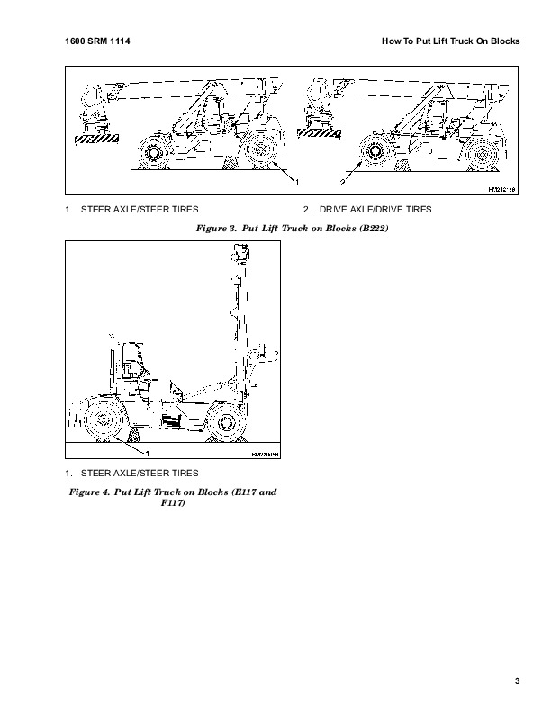
How To Put Lift Truck On Blocks…115
How to Lift Steer Tires…115
Steering Axle Assembly…117
Remove…117
Install…118
Wheels and Hubs…119
Remove and Disassemble…119
Clean…119
Assemble and Install…120
Spindles, Bearings, and Tie Rods…121
Remove…121
Install…122
Steering Cylinder…124
Remove and Disassemble…124
Clean and Inspect…125
Assemble and Install…125
Torque Specifications…126
Troubleshooting…126
1565653-2100SRM1116-(01-2007)-UK-EN…130
toc…130
Tilt Cylinders…130
Safety Precautions Maintenance and Repair…131
General…134
Description…134
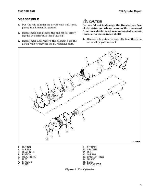
Tilt Cylinder Repair…134
Remove…134
Disassemble…136
Clean…137
Inspect…137
Assemble…137
Install…137
Tilt Cylinder Leak Check…137
Tilt Cylinder Stroke and Mast Tilt Angle Adjustment…138
Torque Specifications…139
Troubleshooting…139
tables…130
Table 1. Movement Rate (Maximum) for Tilt Cylinders…138
1565789-1800SRM1117-(07-2007)-UK-EN…142
toc…142
Parking Brake…142
Safety Precautions Maintenance and Repair…143
General…146
Description and Operation…146
Parking Brake Valve Replacement…146
Remove…146
Clean and Inspect…147
Install…147
Parking Brake Caliper Repair…147
Remove…147
Disassemble…147
Inspect…147
Install…148
Bleed Brakes…150
Adjust…150
Brake Pad Repair…151
Inspect…151
Remove…151
Install…152
Seals Repair…152
Remove…152
Install…152
Specifications…153
Torque Requirements…153
Wear Limits…153
Lining to Disc Clearance…153
Troubleshooting…154
tables…142
Table 1. Brake Pad Adjustment…151
Table 2. Torque Requirements…153
Table 3. Wear Limits…153
Table 4. Lining to Disc Clearance…153
1569718-4000SRM1160-(01-2007)-UK-EN…158
toc…158
Mast…158
Safety Precautions Maintenance and Repair…159
General…162
Description and Operation…162
General…162
Lifting…163
Lowering…163
Safety Procedures When Working Near Mast…163
Forks Repair…164
Adjust…164
Remove…164
Install…164
Low-Mount Fork…164
Carriage Repair…165
General…165
Remove…165
Disassemble…168
Clean and Inspect…170
Assemble…170
Install…172
Carriage Side Blocks…172
Adjust…172
Mast Repair…173
Remove…173
Disassemble…174
Clean and Inspect…176
Assemble…177
Install…179
Lift Cylinders Repair…179
Remove…179
Disassemble…179
Clean and Inspect…180
Assemble…180
Install…180
Fork Positioner Cylinders Repair…181
Remove…181
Disassemble…181
Clean and Inspect…181
Assemble…181
Install…181
Sideshift Cylinder Repair…182
Remove…182
Disassemble…182
Clean and Inspect…182
Assemble…182
Install…182
Header Hoses Replacement…182
Carriage Side Blocks Adjustment…184
Mast Side Blocks Adjustment…184
Mast Load Rollers Adjustment…184
Lift Chains Adjustment…185
Lift and Tilt Cylinders Leak Check…185
Troubleshooting…186
1574068-1400SRM1171-(02-2008)-UK-EN…190
toc…190
Planetary Gear Axle…190
Safety Precautions Maintenance and Repair…191
General…194
Description…194
Operation…194
Planetary Gear Axle Repair…198
Remove…198
Drive Wheels and Tires…198
Disassemble…199
Drive Axle…199
Planetary Gear Carrier…200
Ring Gear, Ring Gear Hub, and Wheel Hub…201
Hub Oil Seal and Bearings…203
Axle Shaft…203
Spindle…203
Repair…204
Repairing or Replacing Parts…204
Welding…204
Clean…205
Ground or Polished Parts…205
Parts With Rough Finishes…205
Axle Assemblies…205
Drying Cleaned Parts…205
Preventing Corrosion…205
Parts Inspection…205
Assemble…206
Spindle…206
Axle Shaft…206
Hub Oil Seal and Bearings…206
Ring Gear, Ring Gear Hub, and Wheel Hub…207
Wheel Bearing Preload…207
Adjust…207
Planetary Gear Carrier…209
Drive Axle…210
Wheel Ends…211
Fill…211
Install…211
Drive Wheels and Tires…211
Torque Specifications…215
Troubleshooting…216
tables…190
Table 1. Wheel Bearing Adjustment Torque…208
Table 2. Planetary Gear Carrier Capscrew and Stud Torque Specifi…210
Table 3. Standard Torque Values for Axle Fasteners…215
1616438-2000SRM1233-(01-2007)-UK-EN…220
toc…220
Hydraulic Plate…220
Safety Precautions Maintenance and Repair…221
General…224
Description and Operation…225
Hydraulic Oil Supply…225
Manifold, Section 1 of Hydraulic Plate…225
Main Control Valve, Section 2 of Hydraulic Plate…225
Description…225
Operation…226
Auxiliary Section…226
Tilt Section…226
Lift Section…226
Return Manifold, Section 3 of Hydraulic Plate…226
Brake Manifold, Section 4 of Hydraulic Plate…230
Cooling Circuit…230
Service Brake…230
Parking Brake…230
Flow Amplifier, Section 5 of Hydraulic Plate…230
Manifold, Section 1 of Hydraulic Plate…230
General…230
Valves and Pressure Switches…231
Main Control Valve, Section 2 of Hydraulic Plate…234
Remove…234
Disassemble…234
Auxiliary Section…234
Lift Section…235
Lift/Tilt Section…237
Clean and Inspect…238
Assemble…238
Auxiliary Section…238
Lift Section…238
Lift/Tilt Section…239
Install…239
Return Manifold, Section 3 of Hydraulic Plate…240
Remove…240
Disassemble…240
Clean and Inspect…241
Assemble…241
Install…241
Brake Manifold, Section 4 of Hydraulic Plate…242
Remove…242
Clean and Inspect…242
Install…242
Flow Amplifier, Section 5 of Hydraulic Plate…243
Hydraulic Hose Repair…243
Hydraulic Hose Identification…243
Torque Values…245
Measurements and Adjustments…246
Measurements…246
Adjustments…246
Troubleshooting…247
tables…220
Table 1. Pilot Hoses…244
Table 2. Brake Hoses…244
Table 3. Auxiliary Hoses With Alternating P and T…244
Table 4. Steer Hoses…244
Table 5. Pressure Settings at 2100 RPM…246
1616439-2200SRM1234-(07-2007)-UK-EN…256
toc…256
Instrument Panel Indicators and Senders…256
Safety Precautions Maintenance and Repair…257
General…260
Description…260
General…260
Instrument Panel Meters, Indicators, and LCD Display…260
Connector…265
Seat Switch Logic…266
Central Warning Light Output…266
Buzzer Output…266
Instrument Panel Component Replacement…268
Instrument Panel…268
Remove…268
Light…269
Replace…269
Sender Replacement…269
Fuel Level Sender…269
Pressure Sender…270
Temperature Sender…270
Low Coolant Sender…271
Vacuum Switch…271
Crankshaft Position Sensor…271
tables…256
Table 1. Instrument Panel and Indicators…261
Table 2. Pin Description…265
Table 3. Sender Description…266
1616442-8000SRM1236-(03-2007)-UK-EN…274
toc…274
Diagrams…274
Safety Precautions Maintenance and Repair…275
1616443-8000SRM1237-(01-2007)-UK-EN…338
toc…338
Periodic Maintenance…338
Safety Precautions Maintenance and Repair…339
General…344
Serial Number Data…344
How to Move Disabled Lift Truck…344
How to Tow Lift Truck…345
How to Put Lift Truck on Blocks…345
How to Raise Drive Tires…345
How to Raise Steering Tires…346
Maintenance Schedule…347
Spreader Maintenance…357
Maintenance Procedures Every 8 Hours or Daily…358
How to Make Checks With the Engine Stopped…358
Safety Labels…358
Operator Restraint System…359
Safety Belt and Seat Rails…359
Steering Column Latch…359
Tires and Wheels…359
Forks…360
Adjust…360
Remove…360
Low Mount Forks, Install…360
Forks, Mast, and Lift Chains, Inspect…361
Drive Belt…362
Crankcase Breather Tube…362
Air Intake Piping and Charge Air Piping…362
Cooling Fan…363
Pre-Cleaner for Air Filter…363
Fuel, Oil, or Coolant Leaks…364
Hydraulic Tank Breather…364
Engine Oil…364
Hydraulic System Oil…365
Hydraulic High Pressure Oil Filter…365
Battery…366
Fuel Filter/Water Separator…366
Cooling System…367
How to Add Fuel to Lift Truck…368
How to Make Checks With Engine Running…368
Gauges, Lights, Horn, Fuses, and Relays…368
Sealed Fuses…371
Transmission Oil…371
Engine Air Filter…371
Engine Oil Pressure…372
Electrical System…372
Steering System…372
Service Brakes…372
Parking Brake…372
Control Levers and Pedals…372
Lift System Operation…372
Attachments…373
First Inspection After First 100 Hours of Operation…373
Engine Oil Filter…373
Drive Axle and Differential…373
Lift Chains…373
Transmission Oil Filter…373
Air Conditioning…373
Steer Wheel Hubs…373
Maintenance Procedures Every 250 Hours Or Monthly…374
Transmission Oil Filter…374
Twist Locks (F117 Only)…374
Gantry Carriage and Container Attachments (F117 Only)…374
Maintenance Procedures Every 500 Hours or 3 Months…374
Drive Belt…374
Lift Chains…374
Hydraulic Return Line Oil Filter…375
Air Conditioning…375
Wheel Nuts…375
Heater Air Filter…375
Steering Axle Kingpins…375
Steering Axle Tie Rods…376
Drive Shaft…376
Steering Axle Pivots…376
Mast and Carriage Load Rollers…376
Mast Pivots, Sliding Surfaces…376
Sideshift Carriage…376
Maintenance Procedures Every 500 Hours or 6 Months…377
Fuel Filter…377
Engine Oil and Filter…377
Oil Filter for Oil-Cooled Brakes (Brake Filter)…377
Transmission Oil…377
Change…377
Maintenance Procedures Every 1000 Hours or 6 Months…378
Drive Axle and Differential Oil…378
Service Brake System…378
Brake System Accumulator…378
Hub Bearings, Steer Wheel s…378
General Lubrication…378
Maintenance Procedures Every 1500 Hours or 1 Year…378
Engine…378
Water Pump…378
Turbocharger…379
Engine Mounting Bolts…379
Air Leaks, Air Intake and Exhaust…380
Valve and Injector Adjustments…381
General…381
Adjust…382
Injector Adjustment…382
Valve Adjustment…383
Maintenance Procedures Every 2000 Hours or 1 Year…385
Parking Brake Assembly…385
Clean…385
Inspect…385
Maintenance Procedures Every 3000 Hours or 18 Months…387
Hydraulic Suction Oil Filters…387
Maintenance Procedures Every 5000 Hours…387
Container Attachment (F117)…387
Maintenance Procedures Every 6000 Hours or 2 Years…387
Vibration Damper…387
Fan Drive Idler Pulley…388
Fan Hub…389
Turbocharger…389
Cooling System Fluid…389
Maintenance Procedures Every 10,000 Hours or 5 Years…390
High Pressure Hydraulic Oil Filter…390
Safety Procedures When Working Near Mast…391
Lift and Tilt System Leaks Check…392
Lift System…392
Tilt System…392
Pneumatic Tires and Wheels…393
Remove Wheels From Lift Truck…393
Remove Tire From Wheel…393
Remove Tire From Five-Piece Wheel…394
Install Tire on Wheel…395
Install Tire on Five-Piece Wheel…396
Add Air Pressure to Tires…397
Install Wheels on Lift Truck…398
tables…338
Table 1. Condition Check…349
Table 2. Daily Inspections − Fluid Level Check…350
Table 3. Daily Inspections − Checks With the Engine Running…351
Table 4. First Inspection After First 100 Hours of Operation…352
Table 5. Periodic Maintenance Schedule − Inspect and Adjust…353
Table 6. Periodic Maintenance Schedule − Lubricate…355
Table 7. Periodic Maintenance Schedule − Change…356
Table 8. Container Attachment Maintenance – Lubricate…358
Table 9. Container Attachment Maintenance − Replace…358
Table 10. Valve and Injector Adjustment Specifications…381
Table 11. Injector and Valve Measurement Sequence…382
1616703-1300SRM1220-(07-2007)-UK-EN…402
toc…402
Transmission…402
Safety Precautions Maintenance and Repair…403
Description of Operation…408
General…408
Torque Convertor, Pump Drive, and Pressure Regulating Valve…409
Input Shaft and Directional Clutches…409
Range Clutches…410
Output Section…410
Transmission Controls…411
Valve Operation…411
Directional Selection…411
Range Selection…412
Neutral Selection…412
Total Neutral Selection…412
Pressure Switch…413
Electric Solenoid Controls…413
Transmission Specifications…442
Transmission Identification…442
Weight, Dimensions, and Oil Capacity…442
Transmission Repair…443
Remove…443
Disassemble…445
Transmission Case, Disassemble…445
Converter Housing, Disassemble…469
Reverse and Second-Speed Clutch…471
Reverse, Disassemble…471
Second-Speed Clutch, Disassemble…475
Forward Clutch, Disassemble…477
Third-Speed Clutch, Disassemble…483
Fourth-Speed Clutch, Disassemble…487
First-Speed Clutch, Disassemble…490
Output Shaft, Disassemble…496
Turbine Shaft, Disassemble…497
Impeller and Baffle, Disassemble…499
Impeller Cover and Turbine Assembly, Disassemble…502
Pump Drive Gear, Disassemble…503
Clean and Inspect…504
Housings…504
Oil Seals and Gaskets…504
Bearings…505
Gears and Shafts…505
Assemble…505
Pump Drive Gear, Assemble…505
Impeller Cover and Turbine, Assemble…506
Impeller and Baffle, Assemble…508
Turbine Shaft, Assemble…511
Output Shaft, Assemble…512
First-Speed Clutch, Assemble…514
Fourth-Speed Clutch, Assemble…521
Third-Speed Clutch, Assemble…525
Forward Clutch, Assemble…531
Reverse and Second-Speed Clutch…537
Second-Speed Clutch, Assemble…537
Reverse Clutch, Assemble…541
Converter Housing, Assemble…547
Transmission Case, Assemble…550
Install…571
Speed Sensors…574
Type of Sensors…574
Speed Sensor With 2-Pin Connector…574
Speed Sensor With 3-Pin Connector…574
Speed Sensor, Install…575
Control Valve Repair…576
Remove…576
Disassemble and Assemble…576
Clean and Inspect…576
Housings…578
Oil Seals and Gaskets…578
Install…578
Stall Test…580
Transmission Calibration and Electrical Troubleshooting…581
Userlink®…581
Connection…581
Clutch Filling Calibration…581
Purpose…581
Clutch Filling Calibration Procedure…581
Alternative Clutch Filling Calibration Procedure…582
Heat-up Mode…583
Heat-up Mode Stall Test…583
Inching Pedal Calibration…584
Purpose…584
Brake Pedal Adjustment…584
Inching Pedal Adjustment (Except for C227)…584
Inching Pedal Sensor Adjustment (Except for C227)…585
Inching Pedal Calibration Procedure (Except for C227)…585
Verification/Adjustment of Inching Pedal Sensor When Pedal is Fu…586
Manual Inching Pedal Sensor Calibration Procedure (Except for C2…586
Troubleshooting…586
Transmission Display Warning Codes…587
Access…587
Clear…587
Exit…587
Limp Home Mode…623
Shutdown Mode…624
Pressure Feedback Sensor…624
Transmission Oil Pressure Check…624
Pressure and Temperature Specifications…624
Clutch Discs…628
Electrical Specifications…630
Hydraulic Cooler Lines Specifications…630
Torque Specifications…631
Torque Specifications for Lubricated or Plated Screw Threads…631
Troubleshooting…633
tables…402
Table 1. Electric Solenoid Controls…414
Table 2. 2-Pin Connector Wiring…574
Table 3. 3-Pin Connector Wiring…574
Table 4. Controller Connector J2 Wire to Pin Number Cross Refere…588
Table 5. Controller Connector J1 Wire to Pin Number Cross Refere…589
Table 6. Common Calibration Condition Messages…591
Table 7. Calibration Codes During Calibration…592
Table 8. Error Codes During Calibration…592
Table 9. Display Warning Codes…593
Table 10. Display Warning Exceed Codes…622
Table 11. Type of Warning Codes…623
Table 12. Forward/Reverse Clutch…628
Table 13. First-Speed Clutch…628
Table 14. Second-Speed Clutch…629
Table 15. Third-Speed Clutch…629
Table 16. Fourth-Speed Clutch…630
Table 17. Grade 5…631
Table 18. Grade 8…631
Table 19. Grades 8.8, 10.9, and 12.9…632
Table 20. Elastic Stop Nut Torque…633
Table 21. O-ring Port Plug Torque Chart…633
Table 22. Pipe Plug Torque Chart…633
Table 23. Pipe Plug Torque Chart…633
1616924-1900SRM1239-(01-2007)-UK-EN…638
toc…638
Hydraulic System…638
Safety Precautions Maintenance and Repair…639
General…644
Description and Operation…644
Hydraulic Plate…644
Hydraulic Pumps…645
Cab Manifold…645
Oil Cooled Brakes (Service Brakes)…645
Lift/Tilt Functions…645
Over Lower Interrupt…646
Lift Interrupt…646
Accumulator Charge Disabling Solenoid (ACDS)…646
Heat Exchanger System…646
Steering Control System…646
Brake System…646
Hydraulic Pump Repair…647
Remove…647
Disassemble…647
Tandem Gear Pump…647
Tri-Section Gear Pump…648
Clean and Inspect…649
Assemble…649
Tandem Gear Pump…649
Tri-Section Gear Pump…650
Install…650
Pump Output Check…650
First Method…650
Second Method…651
Cab Manifold…653
Remove…653
Disassemble Valves and Pressure Switches…653
Clean and Inspect…655
Assemble Valves and Pressure Switches…655
Install…655
Lift and Lower Circuit…656
Description…656
Operation…656
Lift Circuit…657
Lowering…657
Lowering Control Valves…657
Repairs…657
General…657
Remote Control Valve…657
Description and Operation…657
Remove…657
Disassemble…658
Clean and Inspect…659
Assemble…659
Install…659
Adjust…660
Lift Manifold…660
Description and Operation…660
Remove…660
Clean and Inspect…660
Assemble and Install…660
Checks and Adjustments…662
Tilt Control Circuit…663
Description…663
Operation…663
Tilt /Lift Spool…663
Relief Valves in Main Control Valve…664
Relief Valves, Tilt Lock…664
Repairs…664
General…664
Relief Valves, Tilt Lock, Disassemble…664
Clean and Inspect…664
Checks and Adjustments…665
Attachment Circuit Valves…665
General…665
Selector Valves Auxiliary Functions…665
Carriage Solenoid Valve…665
Repairs…665
Carriage Solenoid Valve…665
Remove…665
Disassemble…665
Clean and Inspect…667
Assemble…667
Install…667
Checks and Adjustments…667
Other Hydraulic Components…667
Description and Operation…667
Relief Valves in Steering and Lift Circuits…667
Reducer Valve…667
Hydraulic Filters…667
Hydraulic Filters…668
Suction Filters…668
High Pressure Filter…669
Brake Filter…669
Return Line Filters…670
Hydraulic Hose Repair…671
Checks and Adjustments…671
Pilot Setting, Check…671
Return Pressure, Check…671
Main Function Relief Valve Pressure, Check…671
Hydraulic Tank Breathers…673
Specifications…673
Hydraulic Pumps Output at 2100 rpm (Governed Speed)…673
Cummins 300 Hp (224 kW)/335 Hp (250 kW) Engine…673
Relief Valves (Approximate Operating Pressures)…674
Check Port Pressures…674
Main Hydraulic Filters…674
Tank Capacity…674
Torque Specifications…675
Remote Control Valves…675
Attachment Control Valve…675
Carriage Solenoid Valve…675
Troubleshooting…676
Lift and Lower Circuit…676
Tilt Circuit…679
Attachment Circuit Valves…681
Attachment Control Valve…682
Carriage Solenoid Valve…682
Other Hydraulic Components…683
Accumulator Circuit…683
5 MPa ( 725 psi) Pilot Circuit…683
Park Brake Circuit…684
tables…638
Table 1. Brake Treadle Settings…647
Table 2. Gauge Ranges…672
Table 3. Pressure Settings…672
1648455-0100SRM1301-(01-2007)-UK-EN…694
toc…694
Operator's Cab…694
Safety Precautions Maintenance and Repair…695
General…698
Cab Repair…700
Rear Cab Assembly…700
Bottom Cab Assembly…701
Raising and Lowering…701
Raise Cab…701
Lower Cab…702
Cab Repair…702
Remove…702
Install…703
Oil Filling for Tilt System…704
Inching/Brake and Brake Pedals…705
Brake Pedal, Adjust…705
Inching Pedal, Adjust…705
Inching Pedal Sensor, Adjust…705
Inching Cable, Adjust…706
Throttle Pedal Sensor Adjustment…706
Cable Alignment…706
Engine Side…706
Pedal Housing Side…707
Check…707
Adjust…707
Seat Assembly Removal…707
Power-Assist Armrest…708
Adjust…708
Steering Column Repair…709
Remove…709
Install…709
Window Wipers Replacement…710
Window Wiper Assembly, Replace…710
Front Window Wiper Motor Assembly, Replace…710
Rear Window Wiper Motor Assembly, Replace…711
Top Window Wiper Motor Assembly, Replace…711
Window Washer Motors and Pumps…712
Window Wiper and Washer Operating Switches…712
Window Replacement…713
Front Window, Replace…714
Rear Window, Replace…714
Top Window, Replace…714
Door Window, Replace…715
Heater and Air Conditioning Assembly…715
Heater Parts, Replace…717
Heat Control Knob/Switches…718
Heat Control Knob/Cable…718
Adjust…718
Air Control Knob/Cable…719
Adjust…719
Air Filter, Replace…719
Air Conditioning Condenser Fan(s)…719
Remove…719
Install…719
Instruments, Switches, and Controls…720
Switches…720
Controls…721
Fuses, Relays, and Power Sources…723
Fuse Panel…723
Fuses…723
Relays…724
Power Sources…725
Label Replacement…726
1648456-0100SRM1302-(01-2007)-UK-EN…730
toc…730
Frame…730
Safety Precautions Maintenance and Repair…731
General…734
Description…734
Counterweight Repair…735
General…735
Remove…735
Install…736
Covers…737
Remove…737
Install…737
Floor Plates, Handrails, and Steps…739
Hydraulic Tank Repair…741
Remove…741
Repair…743
Small Leaks…743
Large Leaks…743
Clean…743
Steam Method…743
Chemical Solution Method…743
Other Methods of Preparation for Repair…744
Install…744
Suction Screen and Inspection Cover…745
Remove…745
Clean and Inspect…745
Install…746
Fuel Tank Repair…746
Remove…746
Repair…746
Install…746
Exhaust System Repair…749
Remove…749
Install…750
Engine Repair…750
Remove…750
Install…751
Label Replacement…753
tables…730
Table 1. Counterweight Weights (Up to February 2007)…735
Table 2. Counterweight Weights (February 2007 and Up)…735
Table 3. Counterweight Weights…735
1648457-0700SRM1303-(01-2007)-UK-EN…756
toc…756
Multiple Aligned Cooling System…756
Safety Precautions Maintenance and Repair…757
General…760
Description…761
Radiator…761
Radiator Cap…761
Thermostat…761
Water Pump…762
Fan and Fan Shroud…762
Cooling System Checks…762
Radiator…762
Thermostat…762
Water Pump…763
Exhaust Leaks…763
Fan and Fan Shroud…763
Cooling System Repair…763
Remove…763
Install…765
Core Repair…765
Remove…765
Install…765
Radiator Cleaning…766
Drain…766
Clean…766
Fill…766
Troubleshooting…767
1648458-2200SRM1304-(01-2007)-UK-EN…770
toc…770
Electrical System…770
Safety Precautions Maintenance and Repair…771
Description…774
Warning Devices…778
General…778
Description…778
Operator-Controlled Air Horn…778
Reverse Warning Horns/Lights…779
Warning Lights…779
Strobe Lights…779
Brake Lights…779
Hazard Lights…779
Replace…781
General…781
Horns…781
Horn Relay…781
Light Assemblies…781
Flashing Unit…781
Meters, Senders, and Switches…782
General…782
1648459-8000SRM1305-(01-2007)-UK-EN…790
toc…790
Capacities and Specifications…790
Safety Precautions Maintenance and Repair…791
Counterweight Weights…794
Carriage Weights…795
Vehicle Weight…795
Capacities…795
Electrical System…795
Engine Specifications (Cummins QSM11)…796
Mast Weights…796
Lifting and Lowering Speeds…797
Tires…797
Forks…797
Hydraulic System Specifications…798
Torque Specifications…799
Control Valves…799
Electrical System…799
Counterweight (Fabricated)…799
Counterweight (Secondary)…799
Counterweight (Slab)…799
Drive Axle…799
Wheel Bearing Adjusting Nut…799
Differential…799
Transmission…799
Torque Converter…799
Steering…799
Wheel Nuts…800
Carriages (All)…800
tables…790
Table 1. Up to February 2007…794
Table 2. February 2007 and Up…794
Table 3. March 2007 and Up…794
Table 4. Slab Counterweight (Up to February 2007)…794
1648460-8000SRM1306-(01-2007)-UK-EN…804
toc…804
Assembly Guide…804
Safety Precautions Maintenance and Repair…805
List of All Special Tools and Equipment Needed for the Assembly…808
General Considerations Before Starting the Job…808
Preparation of the Components Before Assembly…809
Wheels Check…809
Air Pressure…809
Drive Wheels…810
Steer Wheels…815
Wheel Nut Torque…818
Installation of the Exhaust Extension Pipe…820
Preparation of the Mast…821
Mast…821
Mast Label Placement…823
Safety Procedures When Working Near Mast…824
Mast Installation…824
Mast…824
Tilt Cylinder Pin Installation…826
Truck Header Hoses and Electrical Cable Connections…827
Lights Installation – Operator Compartment…830
General Procedures After Assembly…831
Hydraulic Oil Check…831
Lubrication Points…832
Check Points…832
Checkpoint 1…832
Checkpoint 2…832
Checkpoint 3…832
Checkpoint 4…832
Checkpoint 5…832
General Truck Install Procedures…832
910072-1400SRM0046-(07-2007)-UK-EN…838
toc…838
Differential…838
Safety Precautions Maintenance and Repair…839
General…842
Description…842
Differential Repair…843
Remove…843
Differential Carrier From Axle Housing, Remove…843
Differential and Ring Gear From Differential Carrier, Remove…845
Drive Pinion and Pinion Carrier From Differential Carrier, Remov…847
Disassemble…848
Differential and Ring Gear Assembly, Disassemble…848
Drive Pinion and Pinion Carrier, Disassemble…850
Clean and Inspect…853
Assemble…854
Pinion, Bearings, and Pinion Carrier, Assemble…854
Pinion Bearings, Adjust Preload…854
Press Method…854
Yoke or Flange Method…855
Triple-Lip Seal, Install…856
Pinion Carrier Shim Set, Adjust Thickness (Depth of Pinion)…857
Differential and Ring Gear, Assemble…859
Differential Gears Rotating Torque, Check…861
Differential and Ring Gear Assembly, Install…862
Differential Bearings, Preload Adjust…864
Ring Gear, Runout Check…865
Ring Gear Backlash, Adjust…865
Gear Set, Tooth Contact Pattern Check…867
Thrust Screw, Install and Adjust…870
Install…870
Differential Assembly Into Axle Housing, Install…870
Specifications…872
Troubleshooting…877
tables…838
Table 1. Ring Gear Backlash Adjustment Specifications…867
Table 2. Ring and Pinion Tooth Contact Adjustment…868
Table 3. General Specifications…872
Table 4. Rivet Installation Pressure…872
Table 5. Pinion Adjustment…873
Table 6. Pinion Preload Pressure…873
Table 7. Torque Specifications…874
Table 8. Torque Specifications for Metric Hardware…875
Table 9. Torque Specifications for Metric (Fine) Hardware…876
910091-1900SRM0097-(07-2006)-UK-EN…880
toc…880
Hydraulic Gear Pumps…880
Safety Precautions Maintenance and Repair…881
Description…884
Operation…885
Flow Control Valve…885
Relief Valve…886
Hydraulic Gear Pump Repair…886
Remove…886
Disassemble…887
Clean…887
Inspect…888
Assemble…891
Install…893
Pump Output Check…893
Method No. 1…893
Method No. 2…894
Hydraulic System Air Check…895
Troubleshooting…896
910442-8000SRM0231-(12-2004)-UK-EN…902
toc…902
Metric and Inch (SAE) Fasteners…902
Safety Precautions Maintenance and Repair…903
General…906
Threaded Fasteners…906
Nomenclature, Threads…906
Strength Identification…907
Cotter (Split) Pins…907
Fastener Torque Tables…912
Conversion Table…914
tables…902
Table 1. Bolts and Screws…908
Table 2. Studs and Nuts…909
Table 3. Torque Nuts…910
Table 4. Torque Nuts With Nylon Insert…911
Table 5. Torque Values for Metric Fasteners*…912
Table 6. Torque Values for Inch Fasteners*…913
Table 7. Conversion Table for Metric and English Units…914
Table 8. Cotter Pin Dimensional Data…915
Table 9. Cotter Pin Dimensional Data…916
Table 10. Cotter Pin Dimensional Data…917
Table 11. Cotter Pin Dimensional Data…919
ACCUMULATOR…924
toc…924
Brake Accumulator…924
Safety Precautions Maintenance and Repair…925
General…928
Description and Operation…928
Accumulator Maintenance…928
Precharge Check…928
Precharge Filling…929
Remove…930
Disassemble…930
Clean…932
Inspect…932
Repair…932
Assemble…932
Replace…932
tables…924
Table 1. Accumulator Pressures…929
Aurora_AC…936
912-100-0148_engl_1.pdf…0
Compressors – Applications, Conditions of Use and Liability…937
…0
Filling procedure for refrigerants…0
Do not exceed the maximum operating pressure of the compressor. (see type label)…943
Compressors are machines under pressure and as such require special care in handling…943
Only qualified personnel are allowed to perform any work on refrigeration compressors…943
The national safety regulations, accident prevention regulations, technical rules and specific regulations must be taken into account abolutely…943
Never put the safety switch out of action…943
Prior to commissioning, check wether all teh components installed by the user have been fastened expertly and connected pressure-tight with the compressor…943
Prior to starting the compressor open discharge shut-off valve and suction shut-off valve…943
Do not start the cmpressor in vacuum. Operate the compressor only when the system is charged…943
Caution! Danger of burning because of high surface temperatures…943
Never grab rotating parts during operation. Danger of injury!…943
Avoid all contact with the liquid refrigerant. Any parts of skin that come into contact with it must be treated like chilblains. Wear goggles to protect eyes. If refrigerant nevertheless gets into the eyes, consult a doctor immediately. Wear leather glov…943
Before repairing refrigerant circuits, all refrigerant must be suctioned off as instructed. Note: Even when the unit is empty, there may be some residual pressure. It is advisable to loosen the screws slowly to allow residual pressure to subside. Refri…943
No welding may be performed on any part of the unit or in the near vicinity while it is closed. Regardless whether the unit is filled with refrigerant or empty, heating causes excess pressure which can damage the unit or cause an explosion…943
Full bottles of refrigerant must not be thrown or…943
It is essential to ensure that the refrigerant system is does not become contaminated with chlorine, substances containing chlorine, oil or grease. Evacuation and filling units must be used for R 134a only…943
4. Troubleshooting…944
…944
…944
Check refrigerant level and pressure as instructed in the Technical Information sheet for the unit…944
By wrong refrigerant level there is a danger of compressor malfunction…944
The outcome of too much refrigerant is a oil attenuation and reflux of the refrigerant can cause damages on the valve plate…944
With undercharged refrigerant the compressor will become hotwhich caused a failure. The sealing will be damaged…944
Faulty shaft seals:On older compressors the shaft seal can be damaged when the unit is switched on for first time after a prolonged period of disuse, e.g. if the air-conditioner has not been used during the winter. Seals may become brittle as a result o…944
NoisesMechanical faults in compressors are generally indicated by unusual noises or by unusually quiet or noisy operation. The normal noise made by the seals during operation does not indicate a fault. The most common noises are caused by problems with…944
Electrical faultsA 5A fuse is used for the magnetic coupling on the compressor. The magnetic coupling can be checked by applying the required voltage to the connection socket while the vehicle engine is running. The coupling should start up with a click…944
912-100-0007_e.pdf…0
Technical modifications reserved…945
912-100-0258_e.pdf…0
Condenser unit, 24V…956
…956
…956
…956
…956
part no.:175-FR2-0002…956
Safety advices…956
– we reserve the right to make technical modifications -…956
1Safety advices…957
Maintenance work on the refrigeration circuit:…957
…958
2.2Condenser blowers…958
5Electrical connection…959
every six months – authorised workshop:…960
…960
…960
…960
State of the refrigerant hoses…960
State of the condenser…960
A contaminated condenser has a minimised condensing performance. The cleaning is carried out by blow-out or spraying (do not use a high-pressure cleaner)…960
every month sight checks – Operator…961
…961
…961
…961
State of the refrigerant hoses…961
State of the condenser…961
Check condenser of contamination by dust, insects or parts of plants…961
A contaminated condenser has a minimised condensing performance. The cleaning is carried out by blow-out or spraying (do not use a high-pressure cleaner)…961
Installation of replacement parts…961
8Technical data…961
9Fault diagnosis…962
CUMMINS DIESEL ENGINE FAULT CODE GUIDE…967
toc…967
Cummins Diesel/LPG Engine Fault Code Guide…967
Safety Precautions Maintenance and Repair…968
General…971
Fault Codes…971
Normal Mode…971
Fault Log Mode…971
Access…971
Exit…972
Clear…972
Electronic Throttle Calibration…972
Electronic Throttle Calibration Procedure…972
tables…967
Table 1. Error Code Descriptions…973
DIFFERENTIAL…989
toc…989
Differential…989
Safety Precautions Maintenance and Repair…990
General…993
Description…993
Differential Repair…994
Remove…994
Differential Carrier From Axle Housing, Remove…994
Differential and Ring Gear From Differential Carrier, Remove…996
Drive Pinion and Pinion Carrier From Differential Carrier, Remov…998
Disassemble…999
Differential and Ring Gear Assembly, Disassemble…999
Drive Pinion and Pinion Carrier, Disassemble…1001
Clean and Inspect…1004
Assemble…1005
Pinion, Bearings, and Pinion Carrier, Assemble…1005
Pinion Bearings, Adjust Preload…1005
Press Method…1005
Yoke or Flange Method…1006
Triple-Lip Seal, Install…1007
Pinion Carrier Shim Set, Adjust Thickness (Depth of Pinion)…1008
Differential and Ring Gear, Assemble…1010
Differential Gears Rotating Torque, Check…1012
Differential and Ring Gear Assembly, Install…1013
Differential Bearings, Preload Adjust…1015
Ring Gear, Runout Check…1016
Ring Gear Backlash, Adjust…1016
Gear Set, Tooth Contact Pattern Check…1018
Thrust Screw, Install and Adjust…1021
Install…1021
Differential Assembly Into Axle Housing, Install…1021
Specifications…1023
Troubleshooting…1028
tables…989
Table 1. Ring Gear Backlash Adjustment Specifications…1018
Table 2. Ring and Pinion Tooth Contact Adjustment…1019
Table 3. General Specifications…1023
Table 4. Rivet Installation Pressure…1023
Table 5. Pinion Adjustment…1024
Table 6. Pinion Preload Pressure…1024
Table 7. Torque Specifications…1025
Table 8. Torque Specifications for Metric Hardware…1026
Table 9. Torque Specifications for Metric (Fine) Hardware…1027
FRAME…1031
toc…1031
Frame…1031
Safety Precautions Maintenance and Repair…1032
General…1035
Description…1035
Counterweight Repair…1036
General…1036
Remove…1036
Install…1037
Covers…1038
Remove…1038
Install…1038
Floor Plates, Handrails, and Steps…1040
Hydraulic Tank Repair…1042
Remove…1042
Repair…1044
Small Leaks…1044
Large Leaks…1044
Clean…1044
Steam Method…1044
Chemical Solution Method…1044
Other Methods of Preparation for Repair…1045
Install…1045
Suction Screen and Inspection Cover…1046
Remove…1046
Clean and Inspect…1046
Install…1047
Fuel Tank Repair…1047
Remove…1047
Repair…1047
Install…1047
Exhaust System Repair…1050
Remove…1050
Install…1051
Engine Repair…1051
Remove…1051
Install…1052
Label Replacement…1054
tables…1031
Table 1. Counterweight Weights (Up to February 2007)…1036
Table 2. Counterweight Weights (February 2007 and Up)…1036
Table 3. Counterweight Weights…1036
MULTIPLE ALIGNED COOLING SYSTEM…1057
toc…1057
Multiple Aligned Cooling System…1057
Safety Precautions Maintenance and Repair…1058
General…1061
Description…1062
Radiator…1062
Radiator Cap…1062
Thermostat…1062
Water Pump…1063
Fan and Fan Shroud…1063
Cooling System Checks…1063
Radiator…1063
Thermostat…1063
Water Pump…1064
Exhaust Leaks…1064
Fan and Fan Shroud…1064
Cooling System Repair…1064
Remove…1064
Install…1066
Core Repair…1066
Remove…1066
Install…1066
Radiator Cleaning…1067
Drain…1067
Clean…1067
Fill…1067
Troubleshooting…1068
OPERATOR''S CAB…1071
toc…1071
Operator's Cab…1071
Safety Precautions Maintenance and Repair…1072
General…1075
Cab Repair…1077
Rear Cab Assembly…1077
Bottom Cab Assembly…1078
Raising and Lowering…1078
Raise Cab…1078
Lower Cab…1079
Cab Repair…1079
Remove…1079
Install…1080
Oil Filling for Tilt System…1081
Inching/Brake and Brake Pedals…1082
Brake Pedal, Adjust…1082
Inching Pedal, Adjust…1082
Inching Pedal Sensor, Adjust…1082
Inching Cable, Adjust…1083
Throttle Pedal Sensor Adjustment…1083
Cable Alignment…1083
Engine Side…1083
Pedal Housing Side…1084
Check…1084
Adjust…1084
Seat Assembly Removal…1084
Power-Assist Armrest…1085
Adjust…1085
Steering Column Repair…1086
Remove…1086
Install…1086
Window Wipers Replacement…1087
Window Wiper Assembly, Replace…1087
Front Window Wiper Motor Assembly, Replace…1087
Rear Window Wiper Motor Assembly, Replace…1088
Top Window Wiper Motor Assembly, Replace…1088
Window Washer Motors and Pumps…1089
Window Wiper and Washer Operating Switches…1089
Window Replacement…1090
Front Window, Replace…1091
Rear Window, Replace…1091
Top Window, Replace…1091
Door Window, Replace…1092
Heater and Air Conditioning Assembly…1092
Heater Parts, Replace…1094
Heat Control Knob/Switches…1095
Heat Control Knob/Cable…1095
Adjust…1095
Air Control Knob/Cable…1096
Adjust…1096
Air Filter, Replace…1096
Air Conditioning Condenser Fan(s)…1096
Remove…1096
Install…1096
Instruments, Switches, and Controls…1097
Switches…1097
Controls…1098
Fuses, Relays, and Power Sources…1100
Fuse Panel…1100
Fuses…1100
Relays…1101
Power Sources…1102
Label Replacement…1103
PLANETARY GEAR AXLE…1107
toc…1107
Planetary Gear Axle…1107
Safety Precautions Maintenance and Repair…1108
General…1111
Description…1111
Operation…1111
Planetary Gear Axle Repair…1115
Remove…1115
Drive Wheels and Tires…1115
Disassemble…1116
Drive Axle…1116
Planetary Gear Carrier…1117
Ring Gear, Ring Gear Hub, and Wheel Hub…1118
Hub Oil Seal and Bearings…1120
Axle Shaft…1120
Spindle…1120
Repair…1121
Repairing or Replacing Parts…1121
Welding…1121
Clean…1122
Ground or Polished Parts…1122
Parts With Rough Finishes…1122
Axle Assemblies…1122
Drying Cleaned Parts…1122
Preventing Corrosion…1122
Parts Inspection…1122
Assemble…1123
Spindle…1123
Axle Shaft…1123
Hub Oil Seal and Bearings…1123
Ring Gear, Ring Gear Hub, and Wheel Hub…1124
Wheel Bearing Preload…1124
Adjust…1124
Planetary Gear Carrier…1126
Drive Axle…1127
Wheel Ends…1128
Fill…1128
Install…1128
Drive Wheels and Tires…1128
Torque Specifications…1132
Troubleshooting…1133
tables…1107
Table 1. Wheel Bearing Adjustment Torque…1125
Table 2. Planetary Gear Carrier Capscrew and Stud Torque Specifi…1127
Table 3. Standard Torque Values for Axle Fasteners…1132
STEERING AXLE…1137
toc…1137
Steering Axle…1137
Safety Precautions Maintenance and Repair…1138
General…1141
Description…1141
How To Put Lift Truck On Blocks…1142
How to Lift Steer Tires…1142
Steering Axle Assembly…1144
Remove…1144
Install…1145
Wheels and Hubs…1146
Remove and Disassemble…1146
Clean…1146
Assemble and Install…1147
Spindles, Bearings, and Tie Rods…1148
Remove…1148
Install…1149
Steering Cylinder…1151
Remove and Disassemble…1151
Clean and Inspect…1152
Assemble and Install…1152
Torque Specifications…1153
Troubleshooting…1153
STEERING SYSTEM…1157
toc…1157
Steering System…1157
Safety Precautions Maintenance and Repair…1158
General…1161
Description…1161
Steering Wheel and Column Assembly Repair…1163
General…1163
Steering Wheel and Horn…1163
Remove…1163
Install…1163
Steering Column…1165
Remove…1165
Install…1165
Steering Control Unit Repair…1166
General…1166
Description…1166
Operation…1166
Remove…1166
Disassemble…1168
Clean…1171
Assemble…1171
Install…1177
Steering System Air Removal…1177
Steering Relief Pressure Check and Adjustments…1177
Flow Amplifier Repair…1179
General…1179
Description…1179
Operation…1179
Neutral Position…1179
During Steering Function…1179
Manual Steering Function…1181
Disassemble…1181
Pressure Relief Valve…1181
End Cover at PP Port…1181
End Cover at LS Port…1181
Spools…1182
Directional Valve Spool…1182
Priority Valve Spool…1182
Pressure Control/Amplifier Valve Spool…1182
Check Valve…1183
Cushion/Suction Valves…1183
Clean…1184
Assemble…1184
Troubleshooting…1185
TRANSMISSION TE27 AND TE32…1189
toc…1189
Transmission…1189
Safety Precautions Maintenance and Repair…1190
Description of Operation…1195
General…1195
Torque Convertor, Pump Drive, and Pressure Regulating Valve…1196
Input Shaft and Directional Clutches…1196
Range Clutches…1197
Output Section…1197
Transmission Controls…1198
Valve Operation…1198
Directional Selection…1198
Range Selection…1199
Neutral Selection…1199
Total Neutral Selection…1199
Pressure Switch…1200
Electric Solenoid Controls…1200
Transmission Specifications…1229
Transmission Identification…1229
Weight, Dimensions, and Oil Capacity…1229
Transmission Repair…1230
Remove…1230
Disassemble…1232
Transmission Case, Disassemble…1232
Converter Housing, Disassemble…1256
Reverse and Second-Speed Clutch…1258
Reverse, Disassemble…1258
Second-Speed Clutch, Disassemble…1262
Forward Clutch, Disassemble…1264
Third-Speed Clutch, Disassemble…1270
Fourth-Speed Clutch, Disassemble…1274
First-Speed Clutch, Disassemble…1277
Output Shaft, Disassemble…1283
Turbine Shaft, Disassemble…1284
Impeller and Baffle, Disassemble…1286
Impeller Cover and Turbine Assembly, Disassemble…1289
Pump Drive Gear, Disassemble…1290
Clean and Inspect…1291
Housings…1291
Oil Seals and Gaskets…1291
Bearings…1292
Gears and Shafts…1292
Assemble…1292
Pump Drive Gear, Assemble…1292
Impeller Cover and Turbine, Assemble…1293
Impeller and Baffle, Assemble…1295
Turbine Shaft, Assemble…1298
Output Shaft, Assemble…1299
First-Speed Clutch, Assemble…1301
Fourth-Speed Clutch, Assemble…1308
Third-Speed Clutch, Assemble…1312
Forward Clutch, Assemble…1318
Reverse and Second-Speed Clutch…1324
Second-Speed Clutch, Assemble…1324
Reverse Clutch, Assemble…1328
Converter Housing, Assemble…1334
Transmission Case, Assemble…1337
Install…1358
Speed Sensors…1361
Type of Sensors…1361
Speed Sensor With 2-Pin Connector…1361
Speed Sensor With 3-Pin Connector…1361
Speed Sensor, Install…1362
Control Valve Repair…1363
Remove…1363
Disassemble and Assemble…1363
Clean and Inspect…1363
Housings…1365
Oil Seals and Gaskets…1365
Install…1365
Stall Test…1367
Transmission Calibration and Electrical Troubleshooting…1368
Userlink®…1368
Connection…1368
Clutch Filling Calibration…1368
Purpose…1368
Clutch Filling Calibration Procedure…1368
Alternative Clutch Filling Calibration Procedure…1369
Heat-up Mode…1370
Heat-up Mode Stall Test…1370
Inching Pedal Calibration…1371
Purpose…1371
Brake Pedal Adjustment…1371
Inching Pedal Adjustment (Except for C227)…1371
Inching Pedal Sensor Adjustment (Except for C227)…1372
Inching Pedal Calibration Procedure (Except for C227)…1372
Verification/Adjustment of Inching Pedal Sensor When Pedal is Fu…1373
Manual Inching Pedal Sensor Calibration Procedure (Except for C2…1373
Troubleshooting…1373
Transmission Display Warning Codes…1374
Access…1374
Clear…1374
Exit…1374
Limp Home Mode…1410
Shutdown Mode…1411
Pressure Feedback Sensor…1411
Transmission Oil Pressure Check…1411
Pressure and Temperature Specifications…1411
Clutch Discs…1415
Electrical Specifications…1417
Hydraulic Cooler Lines Specifications…1417
Torque Specifications…1418
Torque Specifications for Lubricated or Plated Screw Threads…1418
Troubleshooting…1420
tables…1189
Table 1. Electric Solenoid Controls…1201
Table 2. 2-Pin Connector Wiring…1361
Table 3. 3-Pin Connector Wiring…1361
Table 4. Controller Connector J2 Wire to Pin Number Cross Refere…1375
Table 5. Controller Connector J1 Wire to Pin Number Cross Refere…1376
Table 6. Common Calibration Condition Messages…1378
Table 7. Calibration Codes During Calibration…1379
Table 8. Error Codes During Calibration…1379
Table 9. Display Warning Codes…1380
Table 10. Display Warning Exceed Codes…1409
Table 11. Type of Warning Codes…1410
Table 12. Forward/Reverse Clutch…1415
Table 13. First-Speed Clutch…1415
Table 14. Second-Speed Clutch…1416
Table 15. Third-Speed Clutch…1416
Table 16. Fourth-Speed Clutch…1417
Table 17. Grade 5…1418
Table 18. Grade 8…1418
Table 19. Grades 8.8, 10.9, and 12.9…1419
Table 20. Elastic Stop Nut Torque…1420
Table 21. O-ring Port Plug Torque Chart…1420
Table 22. Pipe Plug Torque Chart…1420
Table 23. Pipe Plug Torque Chart…1420
A917 (H800-900-1050HD, H800-900-970-1050HDS)…1425
1529749-1800SRM1036-(07-2007)-US-EN…1426
toc…1426
Brake Accumulator…1426
Safety Precautions Maintenance and Repair…1427
General…1430
Description and Operation…1430
Accumulator Maintenance…1430
Precharge Check…1430
Precharge Filling…1431
Remove…1432
Disassemble…1432
Clean…1434
Inspect…1434
Repair…1434
Assemble…1434
Replace…1434
tables…1426
Table 1. Accumulator Pressures…1431
1531822-1800SRM1038-(07-2007)-US-EN…1438
toc…1438
Service Brake…1438
Safety Precautions Maintenance and Repair…1439
General…1442
Description and Operation…1442
A917, E117, and F117 Only…1442
B222 Only…1442
Repair…1444
General…1444
Remove…1444
Drive Wheels and Tires…1444
Brake Housing…1445
Spindle and Brake Cover…1447
Disassemble…1448
Clean…1450
Ground and Polished Parts…1450
Parts With Rough Finish…1450
Wet Disc Brake and Axle Assembly…1450
Inspect…1450
Face Seals…1450
Disc…1451
Wear Limits…1451
Replace…1451
Parts…1451
Assemble…1452
Brake Housings…1452
Install…1454
Hub Oil Seals…1454
Double Seals…1454
Single Seal…1455
Spindle and Brake Cover…1456
Brake Housing…1457
Drive Wheels and Tires…1460
Pressure Switch…1464
Replace…1464
Accumulator…1464
Brake Pedal Valves (Treadle Valves) Repair…1464
All Models Except A917, B222, E117, and F117…1464
Remove…1464
Clean and Inspect…1464
Install…1465
A917, B222, E117, and F117…1468
Remove…1468
Clean and Inspect…1468
Install…1468
Brake System Air Removal…1468
Specifications…1469
Brake Coolant…1472
Coolant Change Intervals…1472
Normal Maintenance…1472
Hydraulic Fluid…1472
Troubleshooting…1473
tables…1438
Table 1. Friction Disc…1451
Table 2. Stationary Disc…1451
Table 3. Wheel Hub and Brake Housing Torque Chart…1470
Table 4. Brake Housing Cover Torque Chart…1472
1564053-0600SRM1101-(11-2007)-US-EN…1478
toc…1478
Cummins Diesel/LPG Engine Fault Code Guide…1478
Safety Precautions Maintenance and Repair…1479
General…1482
Fault Codes…1482
Normal Mode…1482
Fault Log Mode…1482
Access…1482
Exit…1483
Clear…1483
Electronic Throttle Calibration…1483
Electronic Throttle Calibration Procedure…1483
tables…1478
Table 1. Error Code Descriptions…1484
1565182-1600SRM1109-(07-2007)-US-EN…1500
toc…1500
Steering System…1500
Safety Precautions Maintenance and Repair…1501
General…1504
Description…1504
Steering Wheel and Column Assembly Repair…1506
General…1506
Steering Wheel and Horn…1506
Remove…1506
Install…1506
Steering Column…1508
Remove…1508
Install…1508
Steering Control Unit Repair…1509
General…1509
Description…1509
Operation…1509
Remove…1509
Disassemble…1511
Clean…1514
Assemble…1514
Install…1520
Steering System Air Removal…1520
Steering Relief Pressure Check and Adjustments…1520
Flow Amplifier Repair…1522
General…1522
Description…1522
Operation…1522
Neutral Position…1522
During Steering Function…1522
Manual Steering Function…1524
Disassemble…1524
Pressure Relief Valve…1524
End Cover at PP Port…1524
End Cover at LS Port…1524
Spools…1525
Directional Valve Spool…1525
Priority Valve Spool…1525
Pressure Control/Amplifier Valve Spool…1525
Check Valve…1526
Cushion/Suction Valves…1526
Clean…1527
Assemble…1527
Troubleshooting…1528
1565582-1600SRM1114-(07-2007)-US-EN…1532
toc…1532
Steering Axle…1532
Safety Precautions Maintenance and Repair…1533
General…1536
Description…1536
How To Put Lift Truck On Blocks…1537
How to Lift Steer Tires…1537
Steering Axle Assembly…1539
Remove…1539
Install…1540
Wheels and Hubs…1541
Remove and Disassemble…1541
Clean…1541
Assemble and Install…1542
Spindles, Bearings, and Tie Rods…1543
Remove…1543
Install…1544
Steering Cylinder…1546
Remove and Disassemble…1546
Clean and Inspect…1547
Assemble and Install…1547
Torque Specifications…1548
Troubleshooting…1548
1565653-2100SRM1116-(01-2007)-US-EN…1552
toc…1552
Tilt Cylinders…1552
Safety Precautions Maintenance and Repair…1553
General…1556
Description…1556
Tilt Cylinder Repair…1556
Remove…1556
Disassemble…1558
Clean…1559
Inspect…1559
Assemble…1559
Install…1559
Tilt Cylinder Leak Check…1559
Tilt Cylinder Stroke and Mast Tilt Angle Adjustment…1560
Torque Specifications…1561
Troubleshooting…1561
tables…1552
Table 1. Movement Rate (Maximum) for Tilt Cylinders…1560
1565789-1800SRM1117-(07-2007)-US-EN…1564
toc…1564
Parking Brake…1564
Safety Precautions Maintenance and Repair…1565
General…1568
Description and Operation…1568
Parking Brake Valve Replacement…1568
Remove…1568
Clean and Inspect…1569
Install…1569
Parking Brake Caliper Repair…1569
Remove…1569
Disassemble…1569
Inspect…1569
Install…1570
Bleed Brakes…1572
Adjust…1572
Brake Pad Repair…1573
Inspect…1573
Remove…1573
Install…1574
Seals Repair…1574
Remove…1574
Install…1574
Specifications…1575
Torque Requirements…1575
Wear Limits…1575
Lining to Disc Clearance…1575
Troubleshooting…1576
tables…1564
Table 1. Brake Pad Adjustment…1573
Table 2. Torque Requirements…1575
Table 3. Wear Limits…1575
Table 4. Lining to Disc Clearance…1575
1569718-4000SRM1160-(01-2007)-US-EN…1580
toc…1580
Mast…1580
Safety Precautions Maintenance and Repair…1581
General…1584
Description and Operation…1584
General…1584
Lifting…1585
Lowering…1585
Safety Procedures When Working Near Mast…1585
Forks Repair…1586
Adjust…1586
Remove…1586
Install…1586
Low-Mount Fork…1586
Carriage Repair…1587
General…1587
Remove…1587
Disassemble…1590
Clean and Inspect…1592
Assemble…1592
Install…1594
Carriage Side Blocks…1594
Adjust…1594
Mast Repair…1595
Remove…1595
Disassemble…1596
Clean and Inspect…1598
Assemble…1599
Install…1601
Lift Cylinders Repair…1601
Remove…1601
Disassemble…1601
Clean and Inspect…1602
Assemble…1602
Install…1602
Fork Positioner Cylinders Repair…1603
Remove…1603
Disassemble…1603
Clean and Inspect…1603
Assemble…1603
Install…1603
Sideshift Cylinder Repair…1604
Remove…1604
Disassemble…1604
Clean and Inspect…1604
Assemble…1604
Install…1604
Header Hoses Replacement…1604
Carriage Side Blocks Adjustment…1606
Mast Side Blocks Adjustment…1606
Mast Load Rollers Adjustment…1606
Lift Chains Adjustment…1607
Lift and Tilt Cylinders Leak Check…1607
Troubleshooting…1608
1574068-1400SRM1171-(02-2008)-US-EN…1612
toc…1612
Planetary Gear Axle…1612
Safety Precautions Maintenance and Repair…1613
General…1616
Description…1616
Operation…1616
Planetary Gear Axle Repair…1620
Remove…1620
Drive Wheels and Tires…1620
Disassemble…1621
Drive Axle…1621
Planetary Gear Carrier…1622
Ring Gear, Ring Gear Hub, and Wheel Hub…1623
Hub Oil Seal and Bearings…1625
Axle Shaft…1625
Spindle…1625
Repair…1626
Repairing or Replacing Parts…1626
Welding…1626
Clean…1627
Ground or Polished Parts…1627
Parts With Rough Finishes…1627
Axle Assemblies…1627
Drying Cleaned Parts…1627
Preventing Corrosion…1627
Parts Inspection…1627
Assemble…1628
Spindle…1628
Axle Shaft…1628
Hub Oil Seal and Bearings…1628
Ring Gear, Ring Gear Hub, and Wheel Hub…1629
Wheel Bearing Preload…1629
Adjust…1629
Planetary Gear Carrier…1630
Drive Axle…1631
Wheel Ends…1632
Fill…1632
Install…1632
Drive Wheels and Tires…1632
Torque Specifications…1636
Troubleshooting…1637
tables…1612
Table 1. Wheel Bearing Adjustment Torque…1629
Table 2. Planetary Gear Carrier Capscrew and Stud Torque Specifi…1631
Table 3. Standard Torque Values for Axle Fasteners…1636
1616438-2000SRM1233-(01-2007)-US-EN…1640
toc…1640
Hydraulic Plate…1640
Safety Precautions Maintenance and Repair…1641
General…1644
Description and Operation…1645
Hydraulic Oil Supply…1645
Manifold, Section 1 of Hydraulic Plate…1645
Main Control Valve, Section 2 of Hydraulic Plate…1645
Description…1645
Operation…1646
Auxiliary Section…1646
Tilt Section…1646
Lift Section…1646
Return Manifold, Section 3 of Hydraulic Plate…1646
Brake Manifold, Section 4 of Hydraulic Plate…1650
Cooling Circuit…1650
Service Brake…1650
Parking Brake…1650
Flow Amplifier, Section 5 of Hydraulic Plate…1650
Manifold, Section 1 of Hydraulic Plate…1650
General…1650
Valves and Pressure Switches…1651
Main Control Valve, Section 2 of Hydraulic Plate…1654
Remove…1654
Disassemble…1654
Auxiliary Section…1654
Lift Section…1655
Lift/Tilt Section…1657
Clean and Inspect…1658
Assemble…1658
Auxiliary Section…1658
Lift Section…1658
Lift/Tilt Section…1659
Install…1659
Return Manifold, Section 3 of Hydraulic Plate…1660
Remove…1660
Disassemble…1660
Clean and Inspect…1661
Assemble…1661
Install…1661
Brake Manifold, Section 4 of Hydraulic Plate…1662
Remove…1662
Clean and Inspect…1662
Install…1662
Flow Amplifier, Section 5 of Hydraulic Plate…1663
Hydraulic Hose Repair…1663
Hydraulic Hose Identification…1663
Torque Values…1665
Measurements and Adjustments…1666
Measurements…1666
Adjustments…1666
Troubleshooting…1667
tables…1640
Table 1. Pilot Hoses…1664
Table 2. Brake Hoses…1664
Table 3. Auxiliary Hoses With Alternating P and T…1664
Table 4. Steer Hoses…1664
Table 5. Pressure Settings at 2100 RPM…1666
1616439-2200SRM1234-(07-2007)-US-EN…1676
toc…1676
Instrument Panel Indicators and Senders…1676
Safety Precautions Maintenance and Repair…1677
General…1680
Description…1680
General…1680
Instrument Panel Meters, Indicators, and LCD Display…1680
Connector…1685
Seat Switch Logic…1686
Central Warning Light Output…1686
Buzzer Output…1686
Instrument Panel Component Replacement…1688
Instrument Panel…1688
Remove…1688
Light…1689
Replace…1689
Sender Replacement…1689
Fuel Level Sender…1689
Pressure Sender…1690
Temperature Sender…1690
Low Coolant Sender…1691
Vacuum Switch…1691
Crankshaft Position Sensor…1691
tables…1676
Table 1. Instrument Panel and Indicators…1681
Table 2. Pin Description…1685
Table 3. Sender Description…1686
1616442-8000SRM1236-(03-2007)-US-EN…1694
toc…1694
Diagrams…1694
Safety Precautions Maintenance and Repair…1695
1616443-8000SRM1237-(01-2007)-US-EN…1758
toc…1758
Periodic Maintenance…1758
Safety Precautions Maintenance and Repair…1759
General…1764
Serial Number Data…1764
How to Move Disabled Lift Truck…1764
How to Tow Lift Truck…1765
How to Put Lift Truck on Blocks…1765
How to Raise Drive Tires…1765
How to Raise Steering Tires…1766
Maintenance Schedule…1767
Spreader Maintenance…1777
Maintenance Procedures Every 8 Hours or Daily…1778
How to Make Checks With the Engine Stopped…1778
Safety Labels…1778
Operator Restraint System…1779
Safety Belt and Seat Rails…1779
Steering Column Latch…1779
Tires and Wheels…1779
Forks…1780
Adjust…1780
Remove…1780
Low Mount Forks, Install…1780
Forks, Mast, and Lift Chains, Inspect…1781
Drive Belt…1782
Crankcase Breather Tube…1782
Air Intake Piping and Charge Air Piping…1782
Cooling Fan…1783
Pre-Cleaner for Air Filter…1783
Fuel, Oil, or Coolant Leaks…1784
Hydraulic Tank Breather…1784
Engine Oil…1784
Hydraulic System Oil…1785
Hydraulic High Pressure Oil Filter…1785
Battery…1786
Fuel Filter/Water Separator…1786
Cooling System…1787
How to Add Fuel to Lift Truck…1788
How to Make Checks With Engine Running…1788
Gauges, Lights, Horn, Fuses, and Relays…1788
Sealed Fuses…1791
Transmission Oil…1791
Engine Air Filter…1791
Engine Oil Pressure…1792
Electrical System…1792
Steering System…1792
Service Brakes…1792
Parking Brake…1792
Control Levers and Pedals…1792
Lift System Operation…1792
Attachments…1793
First Inspection After First 100 Hours of Operation…1793
Engine Oil Filter…1793
Drive Axle and Differential…1793
Lift Chains…1793
Transmission Oil Filter…1793
Air Conditioning…1793
Steer Wheel Hubs…1793
Maintenance Procedures Every 250 Hours Or Monthly…1794
Transmission Oil Filter…1794
Twist Locks (F117 Only)…1794
Gantry Carriage and Container Attachments (F117 Only)…1794
Maintenance Procedures Every 500 Hours or 3 Months…1794
Drive Belt…1794
Lift Chains…1794
Hydraulic Return Line Oil Filter…1795
Air Conditioning…1795
Wheel Nuts…1795
Heater Air Filter…1795
Steering Axle Kingpins…1795
Steering Axle Tie Rods…1796
Drive Shaft…1796
Steering Axle Pivots…1796
Mast and Carriage Load Rollers…1796
Mast Pivots, Sliding Surfaces…1796
Sideshift Carriage…1796
Maintenance Procedures Every 500 Hours or 6 Months…1797
Fuel Filter…1797
Engine Oil and Filter…1797
Oil Filter for Oil-Cooled Brakes (Brake Filter)…1797
Transmission Oil…1797
Change…1797
Maintenance Procedures Every 1000 Hours or 6 Months…1798
Drive Axle and Differential Oil…1798
Service Brake System…1798
Brake System Accumulator…1798
Hub Bearings, Steer Wheel s…1798
General Lubrication…1798
Maintenance Procedures Every 1500 Hours or 1 Year…1798
Engine…1798
Water Pump…1798
Turbocharger…1799
Engine Mounting Bolts…1799
Air Leaks, Air Intake and Exhaust…1800
Valve and Injector Adjustments…1801
General…1801
Adjust…1802
Injector Adjustment…1802
Valve Adjustment…1803
Maintenance Procedures Every 2000 Hours or 1 Year…1805
Parking Brake Assembly…1805
Clean…1805
Inspect…1805
Maintenance Procedures Every 3000 Hours or 18 Months…1807
Hydraulic Suction Oil Filters…1807
Maintenance Procedures Every 5000 Hours…1807
Container Attachment (F117)…1807
Maintenance Procedures Every 6000 Hours or 2 Years…1807
Vibration Damper…1807
Fan Drive Idler Pulley…1808
Fan Hub…1809
Turbocharger…1809
Cooling System Fluid…1809
Maintenance Procedures Every 10,000 Hours or 5 Years…1810
High Pressure Hydraulic Oil Filter…1810
Safety Procedures When Working Near Mast…1811
Lift and Tilt System Leaks Check…1812
Lift System…1812
Tilt System…1812
Pneumatic Tires and Wheels…1813
Remove Wheels From Lift Truck…1813
Remove Tire From Wheel…1813
Remove Tire From Five-Piece Wheel…1814
Install Tire on Wheel…1815
Install Tire on Five-Piece Wheel…1816
Add Air Pressure to Tires…1817
Install Wheels on Lift Truck…1818
tables…1758
Table 1. Condition Check…1769
Table 2. Daily Inspections − Fluid Level Check…1770
Table 3. Daily Inspections − Checks With the Engine Running…1771
Table 4. First Inspection After First 100 Hours of Operation…1772
Table 5. Periodic Maintenance Schedule − Inspect and Adjust…1773
Table 6. Periodic Maintenance Schedule − Lubricate…1775
Table 7. Periodic Maintenance Schedule − Change…1776
Table 8. Container Attachment Maintenance – Lubricate…1778
Table 9. Container Attachment Maintenance − Replace…1778
Table 10. Valve and Injector Adjustment Specifications…1801
Table 11. Injector and Valve Measurement Sequence…1802
1616703-1300SRM1220-(07-2007)-US-EN…1822
toc…1822
Transmission…1822
Safety Precautions Maintenance and Repair…1823
Description of Operation…1828
General…1828
Torque Convertor, Pump Drive, and Pressure Regulating Valve…1829
Input Shaft and Directional Clutches…1829
Range Clutches…1830
Output Section…1830
Transmission Controls…1831
Valve Operation…1831
Directional Selection…1831
Range Selection…1832
Neutral Selection…1832
Total Neutral Selection…1832
Pressure Switch…1833
Electric Solenoid Controls…1833
Transmission Specifications…1862
Transmission Identification…1862
Weight, Dimensions, and Oil Capacity…1862
Transmission Repair…1863
Remove…1863
Disassemble…1865
Transmission Case, Disassemble…1865
Converter Housing, Disassemble…1889
Reverse and Second-Speed Clutch…1891
Reverse, Disassemble…1891
Second-Speed Clutch, Disassemble…1895
Forward Clutch, Disassemble…1897
Third-Speed Clutch, Disassemble…1903
Fourth-Speed Clutch, Disassemble…1907
First-Speed Clutch, Disassemble…1910
Output Shaft, Disassemble…1916
Turbine Shaft, Disassemble…1917
Impeller and Baffle, Disassemble…1919
Impeller Cover and Turbine Assembly, Disassemble…1922
Pump Drive Gear, Disassemble…1923
Clean and Inspect…1924
Housings…1924
Oil Seals and Gaskets…1924
Bearings…1925
Gears and Shafts…1925
Assemble…1925
Pump Drive Gear, Assemble…1925
Impeller Cover and Turbine, Assemble…1926
Impeller and Baffle, Assemble…1928
Turbine Shaft, Assemble…1931
Output Shaft, Assemble…1932
First-Speed Clutch, Assemble…1934
Fourth-Speed Clutch, Assemble…1941
Third-Speed Clutch, Assemble…1945
Forward Clutch, Assemble…1951
Reverse and Second-Speed Clutch…1957
Second-Speed Clutch, Assemble…1957
Reverse Clutch, Assemble…1961
Converter Housing, Assemble…1967
Transmission Case, Assemble…1970
Install…1991
Speed Sensors…1994
Type of Sensors…1994
Speed Sensor With 2-Pin Connector…1994
Speed Sensor With 3-Pin Connector…1994
Speed Sensor, Install…1995
Control Valve Repair…1996
Remove…1996
Disassemble and Assemble…1996
Clean and Inspect…1996
Housings…1998
Oil Seals and Gaskets…1998
Install…1998
Stall Test…2000
Transmission Calibration and Electrical Troubleshooting…2001
Userlink®…2001
Connection…2001
Clutch Filling Calibration…2001
Purpose…2001
Clutch Filling Calibration Procedure…2001
Alternative Clutch Filling Calibration Procedure…2002
Heat-up Mode…2003
Heat-up Mode Stall Test…2003
Inching Pedal Calibration…2004
Purpose…2004
Brake Pedal Adjustment…2004
Inching Pedal Adjustment (Except for C227)…2004
Inching Pedal Sensor Adjustment (Except for C227)…2005
Inching Pedal Calibration Procedure (Except for C227)…2005
Verification/Adjustment of Inching Pedal Sensor When Pedal is Fu…2006
Manual Inching Pedal Sensor Calibration Procedure (Except for C2…2006
Troubleshooting…2006
Transmission Display Warning Codes…2007
Access…2007
Clear…2007
Exit…2007
Limp Home Mode…2043
Shutdown Mode…2044
Pressure Feedback Sensor…2044
Transmission Oil Pressure Check…2044
Pressure and Temperature Specifications…2044
Clutch Discs…2048
Electrical Specifications…2050
Hydraulic Cooler Lines Specifications…2050
Torque Specifications…2051
Torque Specifications for Lubricated or Plated Screw Threads…2051
Troubleshooting…2053
tables…1822
Table 1. Electric Solenoid Controls…1834
Table 2. 2-Pin Connector Wiring…1994
Table 3. 3-Pin Connector Wiring…1994
Table 4. Controller Connector J2 Wire to Pin Number Cross Refere…2008
Table 5. Controller Connector J1 Wire to Pin Number Cross Refere…2009
Table 6. Common Calibration Condition Messages…2011
Table 7. Calibration Codes During Calibration…2012
Table 8. Error Codes During Calibration…2012
Table 9. Display Warning Codes…2013
Table 10. Display Warning Exceed Codes…2042
Table 11. Type of Warning Codes…2043
Table 12. Forward/Reverse Clutch…2048
Table 13. First-Speed Clutch…2048
Table 14. Second-Speed Clutch…2049
Table 15. Third-Speed Clutch…2049
Table 16. Fourth-Speed Clutch…2050
Table 17. Grade 5…2051
Table 18. Grade 8…2051
Table 19. Grades 8.8, 10.9, and 12.9…2052
Table 20. Elastic Stop Nut Torque…2053
Table 21. O-ring Port Plug Torque Chart…2053
Table 22. Pipe Plug Torque Chart…2053
Table 23. Pipe Plug Torque Chart…2053
1616924-1900SRM1239-(01-2007)-US-EN…2058
toc…2058
Hydraulic System…2058
Safety Precautions Maintenance and Repair…2059
General…2064
Description and Operation…2064
Hydraulic Plate…2064
Hydraulic Pumps…2065
Cab Manifold…2065
Oil Cooled Brakes (Service Brakes)…2065
Lift/Tilt Functions…2065
Over Lower Interrupt…2066
Lift Interrupt…2066
Accumulator Charge Disabling Solenoid (ACDS)…2066
Heat Exchanger System…2066
Steering Control System…2066
Brake System…2066
Hydraulic Pump Repair…2067
Remove…2067
Disassemble…2067
Tandem Gear Pump…2067
Tri-Section Gear Pump…2068
Clean and Inspect…2069
Assemble…2069
Tandem Gear Pump…2069
Tri-Section Gear Pump…2070
Install…2070
Pump Output Check…2070
First Method…2070
Second Method…2071
Cab Manifold…2073
Remove…2073
Disassemble Valves and Pressure Switches…2073
Clean and Inspect…2075
Assemble Valves and Pressure Switches…2075
Install…2075
Lift and Lower Circuit…2076
Description…2076
Operation…2076
Lift Circuit…2077
Lowering…2077
Lowering Control Valves…2077
Repairs…2077
General…2077
Remote Control Valve…2077
Description and Operation…2077
Remove…2077
Disassemble…2078
Clean and Inspect…2079
Assemble…2079
Install…2079
Adjust…2080
Lift Manifold…2080
Description and Operation…2080
Remove…2080
Clean and Inspect…2080
Assemble and Install…2080
Checks and Adjustments…2082
Tilt Control Circuit…2083
Description…2083
Operation…2083
Tilt /Lift Spool…2083
Relief Valves in Main Control Valve…2084
Relief Valves, Tilt Lock…2084
Repairs…2084
General…2084
Relief Valves, Tilt Lock, Disassemble…2084
Clean and Inspect…2084
Checks and Adjustments…2085
Attachment Circuit Valves…2085
General…2085
Selector Valves Auxiliary Functions…2085
Carriage Solenoid Valve…2085
Repairs…2085
Carriage Solenoid Valve…2085
Remove…2085
Disassemble…2085
Clean and Inspect…2087
Assemble…2087
Install…2087
Checks and Adjustments…2087
Other Hydraulic Components…2087
Description and Operation…2087
Relief Valves in Steering and Lift Circuits…2087
Reducer Valve…2087
Hydraulic Filters…2087
Hydraulic Filters…2088
Suction Filters…2088
High Pressure Filter…2089
Brake Filter…2089
Return Line Filters…2090
Hydraulic Hose Repair…2091
Checks and Adjustments…2091
Pilot Setting, Check…2091
Return Pressure, Check…2091
Main Function Relief Valve Pressure, Check…2091
Hydraulic Tank Breathers…2093
Specifications…2093
Hydraulic Pumps Output at 2100 rpm (Governed Speed)…2093
Cummins 300 Hp (224 kW)/335 Hp (250 kW) Engine…2093
Relief Valves (Approximate Operating Pressures)…2094
Check Port Pressures…2094
Main Hydraulic Filters…2094
Tank Capacity…2094
Torque Specifications…2095
Remote Control Valves…2095
Attachment Control Valve…2095
Carriage Solenoid Valve…2095
Troubleshooting…2096
Lift and Lower Circuit…2096
Tilt Circuit…2099
Attachment Circuit Valves…2101
Attachment Control Valve…2102
Carriage Solenoid Valve…2102
Other Hydraulic Components…2103
Accumulator Circuit…2103
5 MPa ( 725 psi) Pilot Circuit…2103
Park Brake Circuit…2104
tables…2058
Table 1. Brake Treadle Settings…2067
Table 2. Gauge Ranges…2092
Table 3. Pressure Settings…2092
1648455-0100SRM1301-(01-2007)-US-EN…2114
toc…2114
Operator's Cab…2114
Safety Precautions Maintenance and Repair…2115
General…2118
Cab Repair…2120
Rear Cab Assembly…2120
Bottom Cab Assembly…2121
Raising and Lowering…2121
Raise Cab…2121
Lower Cab…2122
Cab Repair…2122
Remove…2122
Install…2123
Oil Filling for Tilt System…2124
Inching/Brake and Brake Pedals…2125
Brake Pedal, Adjust…2125
Inching Pedal, Adjust…2125
Inching Pedal Sensor, Adjust…2125
Inching Cable, Adjust…2126
Throttle Pedal Sensor Adjustment…2126
Cable Alignment…2126
Engine Side…2126
Pedal Housing Side…2127
Check…2127
Adjust…2127
Seat Assembly Removal…2127
Power-Assist Armrest…2128
Adjust…2128
Steering Column Repair…2129
Remove…2129
Install…2129
Window Wipers Replacement…2130
Window Wiper Assembly, Replace…2130
Front Window Wiper Motor Assembly, Replace…2130
Rear Window Wiper Motor Assembly, Replace…2131
Top Window Wiper Motor Assembly, Replace…2131
Window Washer Motors and Pumps…2132
Window Wiper and Washer Operating Switches…2132
Window Replacement…2133
Front Window, Replace…2134
Rear Window, Replace…2134
Top Window, Replace…2134
Door Window, Replace…2135
Heater and Air Conditioning Assembly…2135
Heater Parts, Replace…2137
Heat Control Knob/Switches…2138
Heat Control Knob/Cable…2138
Adjust…2138
Air Control Knob/Cable…2139
Adjust…2139
Air Filter, Replace…2139
Air Conditioning Condenser Fan(s)…2139
Remove…2139
Install…2139
Instruments, Switches, and Controls…2140
Switches…2140
Controls…2141
Fuses, Relays, and Power Sources…2143
Fuse Panel…2143
Fuses…2143
Relays…2144
Power Sources…2145
Label Replacement…2146
1648456-0100SRM1302-(01-2007)-US-EN…2150
toc…2150
Frame…2150
Safety Precautions Maintenance and Repair…2151
General…2154
Description…2154
Counterweight Repair…2155
General…2155
Remove…2155
Install…2156
Covers…2157
Remove…2157
Install…2157
Floor Plates, Handrails, and Steps…2159
Hydraulic Tank Repair…2161
Remove…2161
Repair…2163
Small Leaks…2163
Large Leaks…2163
Clean…2163
Steam Method…2163
Chemical Solution Method…2163
Other Methods of Preparation for Repair…2164
Install…2164
Suction Screen and Inspection Cover…2165
Remove…2165
Clean and Inspect…2165
Install…2166
Fuel Tank Repair…2166
Remove…2166
Repair…2166
Install…2166
Exhaust System Repair…2169
Remove…2169
Install…2170
Engine Repair…2170
Remove…2170
Install…2171
Label Replacement…2173
tables…2150
Table 1. Counterweight Weights (Up to February 2007)…2155
Table 2. Counterweight Weights (February 2007 and Up)…2155
Table 3. Counterweight Weights…2155
1648457-0700SRM1303-(01-2007)-US-EN…2176
toc…2176
Multiple Aligned Cooling System…2176
Safety Precautions Maintenance and Repair…2177
General…2180
Description…2181
Radiator…2181
Radiator Cap…2181
Thermostat…2181
Water Pump…2182
Fan and Fan Shroud…2182
Cooling System Checks…2182
Radiator…2182
Thermostat…2182
Water Pump…2183
Exhaust Leaks…2183
Fan and Fan Shroud…2183
Cooling System Repair…2183
Remove…2183
Install…2185
Core Repair…2185
Remove…2185
Install…2185
Radiator Cleaning…2186
Drain…2186
Clean…2186
Fill…2186
Troubleshooting…2187
1648458-2200SRM1304-(01-2007)-US-EN…2190
toc…2190
Electrical System…2190
Safety Precautions Maintenance and Repair…2191
Description…2194
Warning Devices…2198
General…2198
Description…2198
Operator-Controlled Air Horn…2198
Reverse Warning Horns/Lights…2199
Warning Lights…2199
Strobe Lights…2199
Brake Lights…2199
Hazard Lights…2199
Replace…2201
General…2201
Horns…2201
Horn Relay…2201
Light Assemblies…2201
Flashing Unit…2201
Meters, Senders, and Switches…2202
General…2202
1648459-8000SRM1305-(01-2007)-US-EN…2210
toc…2210
Capacities and Specifications…2210
Safety Precautions Maintenance and Repair…2211
Counterweight Weights…2214
Carriage Weights…2215
Vehicle Weight…2215
Capacities…2215
Electrical System…2215
Engine Specifications (Cummins QSM11)…2216
Mast Weights…2216
Lifting and Lowering Speeds…2217
Tires…2217
Forks…2217
Hydraulic System Specifications…2218
Torque Specifications…2219
Control Valves…2219
Electrical System…2219
Counterweight (Fabricated)…2219
Counterweight (Secondary)…2219
Counterweight (Slab)…2219
Drive Axle…2219
Wheel Bearing Adjusting Nut…2219
Differential…2219
Transmission…2219
Torque Converter…2219
Steering…2219
Wheel Nuts…2220
Carriages (All)…2220
tables…2210
Table 1. Up to February 2007…2214
Table 2. February 2007 and Up…2214
Table 3. March 2007 and Up…2214
Table 4. Slab Counterweight (Up to February 2007)…2214
1648460-8000SRM1306-(01-2007)-US-EN…2224
toc…2224
Assembly Guide…2224
Safety Precautions Maintenance and Repair…2225
List of All Special Tools and Equipment Needed for the Assembly…2228
General Considerations Before Starting the Job…2228
Preparation of the Components Before Assembly…2229
Wheels Check…2229
Air Pressure…2229
Drive Wheels…2230
Steer Wheels…2235
Wheel Nut Torque…2238
Installation of the Exhaust Extension Pipe…2240
Preparation of the Mast…2241
Mast…2241
Mast Label Placement…2243
Safety Procedures When Working Near Mast…2244
Mast Installation…2244
Mast…2244
Tilt Cylinder Pin Installation…2246
Truck Header Hoses and Electrical Cable Connections…2247
Lights Installation – Operator Compartment…2250
General Procedures After Assembly…2251
Hydraulic Oil Check…2251
Lubrication Points…2252
Check Points…2252
Checkpoint 1…2252
Checkpoint 2…2252
Checkpoint 3…2252
Checkpoint 4…2252
Checkpoint 5…2252
General Truck Install Procedures…2252
910072-1400SRM0046-(07-2007)-US-EN…2258
toc…2258
Differential…2258
Safety Precautions Maintenance and Repair…2259
General…2262
Description…2262
Differential Repair…2263
Remove…2263
Differential Carrier From Axle Housing, Remove…2263
Differential and Ring Gear From Differential Carrier, Remove…2265
Drive Pinion and Pinion Carrier From Differential Carrier, Remov…2267
Disassemble…2268
Differential and Ring Gear Assembly, Disassemble…2268
Drive Pinion and Pinion Carrier, Disassemble…2270
Clean and Inspect…2273
Assemble…2274
Pinion, Bearings, and Pinion Carrier, Assemble…2274
Pinion Bearings, Adjust Preload…2274
Press Method…2274
Yoke or Flange Method…2275
Triple-Lip Seal, Install…2276
Pinion Carrier Shim Set, Adjust Thickness (Depth of Pinion)…2277
Differential and Ring Gear, Assemble…2279
Differential Gears Rotating Torque, Check…2281
Differential and Ring Gear Assembly, Install…2282
Differential Bearings, Preload Adjust…2284
Ring Gear, Runout Check…2285
Ring Gear Backlash, Adjust…2285
Gear Set, Tooth Contact Pattern Check…2287
Thrust Screw, Install and Adjust…2290
Install…2290
Differential Assembly Into Axle Housing, Install…2290
Specifications…2292
Troubleshooting…2297
tables…2258
Table 1. Ring Gear Backlash Adjustment Specifications…2287
Table 2. Ring and Pinion Tooth Contact Adjustment…2288
Table 3. General Specifications…2292
Table 4. Rivet Installation Pressure…2292
Table 5. Pinion Adjustment…2293
Table 6. Pinion Preload Pressure…2293
Table 7. Torque Specifications…2294
Table 8. Torque Specifications for Metric Hardware…2295
Table 9. Torque Specifications for Metric (Fine) Hardware…2296
910091-1900SRM0097-(07-2006)-US-EN…2300
toc…2300
Hydraulic Gear Pumps…2300
Safety Precautions Maintenance and Repair…2301
Description…2304
Operation…2305
Flow Control Valve…2305
Relief Valve…2306
Hydraulic Gear Pump Repair…2306
Remove…2306
Disassemble…2307
Clean…2307
Inspect…2308
Assemble…2311
Install…2313
Pump Output Check…2313
Method No. 1…2313
Method No. 2…2314
Hydraulic System Air Check…2315
Troubleshooting…2316
910442-8000SRM0231-(12-2004)-US-EN…2322
toc…2322
Metric and Inch (SAE) Fasteners…2322
Safety Precautions Maintenance and Repair…2323
General…2326
Threaded Fasteners…2326
Nomenclature, Threads…2326
Strength Identification…2327
Cotter (Split) Pins…2327
Fastener Torque Tables…2332
Conversion Table…2334
tables…2322
Table 1. Bolts and Screws…2328
Table 2. Studs and Nuts…2329
Table 3. Torque Nuts…2330
Table 4. Torque Nuts With Nylon Insert…2331
Table 5. Torque Values for Metric Fasteners*…2332
Table 6. Torque Values for Inch Fasteners*…2333
Table 7. Conversion Table for Metric and English Units…2334
Table 8. Cotter Pin Dimensional Data…2335
Table 9. Cotter Pin Dimensional Data…2336
Table 10. Cotter Pin Dimensional Data…2337
Table 11. Cotter Pin Dimensional Data…2339
Aurora_AC…2344
912-100-0148_engl_1.pdf…0
Compressors – Applications, Conditions of Use and Liability…2345
…0
Filling procedure for refrigerants…0
Do not exceed the maximum operating pressure of the compressor. (see type label)…2351
Compressors are machines under pressure and as such require special care in handling…2351
Only qualified personnel are allowed to perform any work on refrigeration compressors…2351
The national safety regulations, accident prevention regulations, technical rules and specific regulations must be taken into account abolutely…2351
Never put the safety switch out of action…2351
Prior to commissioning, check wether all teh components installed by the user have been fastened expertly and connected pressure-tight with the compressor…2351
Prior to starting the compressor open discharge shut-off valve and suction shut-off valve…2351
Do not start the cmpressor in vacuum. Operate the compressor only when the system is charged…2351
Caution! Danger of burning because of high surface temperatures…2351
Never grab rotating parts during operation. Danger of injury!…2351
Avoid all contact with the liquid refrigerant. Any parts of skin that come into contact with it must be treated like chilblains. Wear goggles to protect eyes. If refrigerant nevertheless gets into the eyes, consult a doctor immediately. Wear leather glov…2351
Before repairing refrigerant circuits, all refrigerant must be suctioned off as instructed. Note: Even when the unit is empty, there may be some residual pressure. It is advisable to loosen the screws slowly to allow residual pressure to subside. Refri…2351
No welding may be performed on any part of the unit or in the near vicinity while it is closed. Regardless whether the unit is filled with refrigerant or empty, heating causes excess pressure which can damage the unit or cause an explosion…2351
Full bottles of refrigerant must not be thrown or…2351
It is essential to ensure that the refrigerant system is does not become contaminated with chlorine, substances containing chlorine, oil or grease. Evacuation and filling units must be used for R 134a only…2351
4. Troubleshooting…2352
…2352
…2352
Check refrigerant level and pressure as instructed in the Technical Information sheet for the unit…2352
By wrong refrigerant level there is a danger of compressor malfunction…2352
The outcome of too much refrigerant is a oil attenuation and reflux of the refrigerant can cause damages on the valve plate…2352
With undercharged refrigerant the compressor will become hotwhich caused a failure. The sealing will be damaged…2352
Faulty shaft seals:On older compressors the shaft seal can be damaged when the unit is switched on for first time after a prolonged period of disuse, e.g. if the air-conditioner has not been used during the winter. Seals may become brittle as a result o…2352
NoisesMechanical faults in compressors are generally indicated by unusual noises or by unusually quiet or noisy operation. The normal noise made by the seals during operation does not indicate a fault. The most common noises are caused by problems with…2352
Electrical faultsA 5A fuse is used for the magnetic coupling on the compressor. The magnetic coupling can be checked by applying the required voltage to the connection socket while the vehicle engine is running. The coupling should start up with a click…2352
912-100-0007_e.pdf…0
Technical modifications reserved…2353
912-100-0258_e.pdf…0
Condenser unit, 24V…2364
part no.:175-FR2-0002…2364
Safety advices…2364
– we reserve the right to make technical modifications -…2364
1Safety advices…2365
Maintenance work on the refrigeration circuit:…2365
…2366
2.2Condenser blowers…2366
5Electrical connection…2367
every six months – authorised workshop:…2368
State of the refrigerant hoses…2368
State of the condenser…2368
A contaminated condenser has a minimised condensing performance. The cleaning is carried out by blow-out or spraying (do not use a high-pressure cleaner)…2368
every month sight checks – Operator…2369
…2369
…2369
…2369
State of the refrigerant hoses…2369
State of the condenser…2369
Check condenser of contamination by dust, insects or parts of plants…2369
A contaminated condenser has a minimised condensing performance. The cleaning is carried out by blow-out or spraying (do not use a high-pressure cleaner)…2369
Installation of replacement parts…2369
8Technical data…2369
9Fault diagnosis…2370

Hyster A917 (H40.00XM-12, H44.00XM-12, H48.00XM-12 Europe & H800-900-1050HD, H800-900-970-1050HDS) Repair Service Manual


INSTANT DOWNLOAD


Posted on

Hyster A236 (H16.00XM-12, H16.00XMS-12, H18.00XM-12, H18.00XMS-12 Europe & H400HD, H400HDS, H450HD, H450HDS) Repair Service Manuals


INSTANT DOWNLOAD


Complete service repair manual for Hyster A236 (H16.00XM-12, H16.00XMS-12, H18.00XM-12, H18.00XMS-12 Europe & H400HD, H400HDS, H450HD, H450HDS), with all the shop information to maintain, diagnose, repair, and rebuild like professional mechanics.

Hyster A236 (H16.00XM-12, H16.00XMS-12, H18.00XM-12, H18.00XMS-12 Europe & H400HD, H400HDS, H450HD, H450HDS) workshop service & repair manual includes:
* Numbered table of contents easy to use so that you can find the information you need fast.
* Detailed sub-steps expand on repair procedure information
* Numbered instructions guide you through every repair procedure step by step.
* Troubleshooting and electrical service procedures are combined with detailed wiring diagrams for ease of use.
* Notes, cautions and warnings throughout each chapter pinpoint critical information.
* Bold figure number help you quickly match illustrations with instructions.
* Detailed illustrations, drawings and photos guide you through every procedure.
* Enlarged inset helps you identify and examine parts in detail.

Hyster A236 (H16.00XM-12, H16.00XMS-12, H18.00XM-12, H18.00XMS-12 Europe & H400HD, H400HDS, H450HD, H450HDS Service Manual.pdf

Total Pages: 1,520 pages
File Format: PDF
Language: English

TABLE OF CONTENTS

 A236 (H16.00XM-12, H16.00XMS-12, H18.00XM-12, H18.00XMS-12 Europe)
    ACCUMULATOR.pdf
    ASSEMBLY GUIDE.pdf
    BRAKE SYSTEM (WET).pdf
    CAPACITIES AND SPECIFICATIONS.pdf
    COOLING SYSTEM.pdf
    CUMMINS DIESEL ENGINE FAULT CODE GUIDE.pdf
    DIAGRAMS.pdf
    DIFFERENTIAL.pdf
    ELECTRICAL SYSTEM.pdf
    FRAME.pdf
    HYDRAULIC PLATE.pdf
    HYDRAULIC SYSTEM.pdf
    INSTRUMENT PANEL INDICATORS AND SENDERS.pdf
    LIFT CYLINDERS (OLD MAST).pdf
    MAST-FORK LIFT TRUCK.pdf
    METRIC AND INCH (SAE) FASTENERS.pdf
    PARKING BRAKE.pdf
    PERIODIC MAINTENANCE.pdf
    PLANETARY GEAR AXLE.pdf
    STEERING AXLE.pdf
    STEERING SYSTEM.pdf
    TE1317 TRANSMISSION.pdf
    TILT CYLINDERS.pdf
A236 (H400HD, H400HDS, H450HD, H450HDS)
     ACCUMULATOR.pdf
     ASSEMBLY GUIDE.pdf
     BRAKE SYSTEM (WET).pdf
     CAPACITIES AND SPECIFICATIONS.pdf
     COOLING SYSTEM.pdf
     CUMMINS DIESELLPG ENGINE FAULT CODE GUIDE.pdf
     DIAGRAMS.pdf
     DIFFERENTIAL.pdf
     ELECTRICAL SYSTEM.pdf
     FRAME.pdf
     HYDRAULIC PLATE.pdf
     HYDRAULIC SYSTEM.pdf
     INSTRUMENT PANEL INDICATORS AND SENDERS.pdf
     LIFT CYLINDERS.pdf
     MAST-FORK LIFT TRUCK.pdf
     METRIC AND INCH (SAE) FASTENERS.pdf
     OPERATOR”S CAB.pdf
     PARKING BRAKE.pdf
     PERIODIC MAINTENANCE.pdf
     PLANETARY GEAR AXLE.pdf
     STEERING AXLE.pdf
     STEERING SYSTEM.pdf
     TE1317 TRANSMISSION.pdf
     TILT CYLINDERS.pdf

A236 (H16.00XM-12, H16.00XMS-12, H18.00XM-12, H18.00XMS-12 Europe)…2
  ACCUMULATOR…3
      Brake Accumulator…3
      Safety Precautions Maintenance and Repair…4
      General…7
      Description and Operation…7
      Accumulator Maintenance…7
        Precharge Check…7
        Precharge Filling…8
        Remove…9
        Disassemble…9
        Clean…11
        Inspect…11
        Repair…11
        Assemble…11
        Replace…11
    tables…3
      Table 1. Accumulator Pressures…8
  ASSEMBLY GUIDE…15
    toc…15
      Assembly Guide…15
      Safety Precautions Maintenance and Repair…16
      List of All Special Tools and Equipment Needed for the Assembly…19
      General Considerations Before Starting the Job…21
      Preparation of the Components Before Assembly…21
      Checking of the Wheels…22
        Air Pressure…22
        Drive Wheels…22
        Steer Wheels…26
        Wheel Nut Torque…29
      Label Placement…30
        Mast Labels…30
      Safety Procedures When Working Near Mast…31
      Mast Installation…32
        Mast…32
        Truck Header Hoses-Part 1…34
        Mast Pin Installation…35
        Tilt Cylinder Pin Installation…37
        Truck Header Hoses-Part 2…39
        Carriage Connection…41
      Exhaust Installation…43
      Lights Installation…44
        Flood…44
        Beacon…44
      Hydraulic Oil Check…45
      Lubrication Points…46
      Check Points…47
        Checkpoint 1…47
        Checkpoint 2…47
        Checkpoint 3…47
        Checkpoint 4…47
        Checkpoint 5…47
      General Truck Installation Procedures…47
    tables…15
      Table 1. Basic Truck Chart…19
      Table 2. Mast Chart…20
      Table 3. Mast Chart…20
      Table 4. Carriage Chart…20
  BRAKE SYSTEM (WET)…51
    toc…51
      Wet Brake System…51
      Safety Precautions Maintenance and Repair…52
      General…55
      Description and Operation…55
        Service Brakes…55
        Parking Brake…55
        Oil Cooler Circuit…55
      Pressure Switch Replacement…59
      Accumulators Replacement…59
      Brake Treadle Valve Repair…59
        Remove and Disassemble…59
        Clean and Inspect…60
        Assemble and Install…60
      Parking Brake Valve Repair…60
        Remove…60
        Clean and Inspect…60
        Repair…60
        Install…60
      Parking Brake Caliper Repair…61
        Remove…61
        Disassemble…63
        Inspect…63
        Install…63
        Adjust…63
      Brake Pad Repair…64
        Inspect…64
        Remove…64
        Install…64
      Seals Repair…64
        Remove…64
        Install…65
      Service Brake Repair…65
        Remove and Disassemble…65
          Drain Lubricating Oil…65
          Drain Coolant Oil…72
          Disconnect Brake Lines…72
          Wheel End With Outer Bearing on Ring Gear Hub Journal H13.00-14…72
          Wheel End With Outer Bearing on Spindle Journal H8.00-12.00XM (H…73
          Brake Disc Housing Assembly Wheel End…74
          Brake Piston Housing…75
          Brake Piston Housing and Wheel Spindle…76
        Inspect…76
        Clean…78
        Assemble…79
          Wheel Spindle…79
          Brake Piston Housing…79
          Piston Assembly…81
          Brake Disc Housing…81
          Duo-Cone Face Seal Into Brake Disc Housing and Into Hub…83
          Check for Correct Installation of Duo-Cone Seal…84
          Wheel Hub to Brake Disc Housing…85
        Adjust…86
          Fill Brake System With Coolant Oil…86
          System Air Removal…87
          Adjust Brake With New Disc Pack…87
          Coolant Change Intervals…88
          Coolant Draining and Filling…88
      Specifications…90
        Minimum Brake Disc Thickness…93
        Hydraulic Fluid for Brake Actuation…93
        Brake Coolant Specifications…93
        Coolant Change Intervals…93
        Hydraulic Fluid Specifications…93
      Troubleshooting…93
        Brake Does Not Apply…93
        Brake Does Not Release…94
        Brake Performance…94
        Brake Leaks Actuation Fluid…95
        Brake Cooling Fluid Leakage…96
        Brake Noise and Vibration…96
        Brake Overheats…96
    tables…51
      Table 1. Brake Pad Adjustment…63
      Table 2. Minimum Brake Disc Thickness…77
      Table 3. Formed Seal Wear Chart…77
  CAPACITIES AND SPECIFICATIONS…101
    toc…101
      Capacities and Specifications…101
      Safety Precautions Maintenance and Repair…102
      Counterweight Weights…105
      Vehicle Weights…105
      Capacities…106
      Electrical System…106
      Engine Specifications…106
      Function Speeds…107
      Steering…108
      Tire Sizes…108
      Hydraulic System Specifications…109
      Torque Specifications…110
        Main Control Valve…110
        Engine…110
        Electrical System…110
          Alternator…110
        Counterweight…110
        Drive Axle…110
        Planetary Gear Axle…110
        Steering Axle…110
        Wheel Bearing Adjusting Nut (PRC1756-W3H)…110
        Differential…110
        Transmission…110
        Torque Converter…111
        Steering…111
        Wheel Nuts…111
    tables…101
      Table 1. Lifting Speeds…107
      Table 2. Lowering Speeds…107
  COOLING SYSTEM…115
    toc…115
      Multiple Aligned Cooling System…115
      Safety Precautions Maintenance and Repair…116
      General…119
      Description…120
        Radiator…120
        Radiator Cap…120
        Thermostat…120
        Water Pump…121
        Fan and Fan Shroud…121
      Cooling System Checks…121
        Radiator…121
        Thermostat…121
        Water Pump…122
        Exhaust Leaks…122
        Fan and Fan Shroud…122
      Cooling System Repair…122
        Remove…122
        Install…123
      Core Repair…123
        Remove…123
        Install…123
      Radiator Cleaning…124
        Drain…124
        Clean…124
        Fill…124
      Troubleshooting…125
  CUMMINS DIESEL ENGINE FAULT CODE GUIDE…129
    toc…129
      Cummins Diesel/LPG Engine Fault Code Guide…129
      Safety Precautions Maintenance and Repair…130
      General…133
      Fault Codes…133
        Normal Mode…133
        Fault Log Mode…133
          Access…133
          Exit…134
          Clear…134
        Electronic Throttle Calibration…134
          Electronic Throttle Calibration Procedure…134
    tables…129
      Table 1. Error Code Descriptions…135
  DIAGRAMS…151
    toc…151
      Diagrams…151
      Safety Precautions Maintenance and Repair…152
  DIFFERENTIAL…179
    toc…179
      Differential…179
      Safety Precautions Maintenance and Repair…180
      General…183
      Description…183
      Differential Repair…184
        Remove…184
          Differential Carrier From Axle Housing, Remove…184
          Differential and Ring Gear From Differential Carrier, Remove…186
          Drive Pinion and Pinion Carrier From Differential Carrier, Remov…188
        Disassemble…189
          Differential and Ring Gear Assembly, Disassemble…189
          Drive Pinion and Pinion Carrier, Disassemble…191
        Clean and Inspect…194
        Assemble…195
          Pinion, Bearings, and Pinion Carrier, Assemble…195
          Pinion Bearings, Adjust Preload…195
            Press Method…195
            Yoke or Flange Method…196
          Triple-Lip Seal, Install…197
          Pinion Carrier Shim Set, Adjust Thickness (Depth of Pinion)…198
          Differential and Ring Gear, Assemble…200
          Differential Gears Rotating Torque, Check…202
          Differential and Ring Gear Assembly, Install…203
          Differential Bearings, Preload Adjust…205
          Ring Gear, Runout Check…206
          Ring Gear Backlash, Adjust…206
          Gear Set, Tooth Contact Pattern Check…208
          Thrust Screw, Install and Adjust…211
        Install…211
          Differential Assembly Into Axle Housing, Install…211
      Specifications…213
      Troubleshooting…218
    tables…179
      Table 1. Ring Gear Backlash Adjustment Specifications…208
      Table 2. Ring and Pinion Tooth Contact Adjustment…209
      Table 3. General Specifications…213
      Table 4. Rivet Installation Pressure…213
      Table 5. Pinion Adjustment…214
      Table 6. Pinion Preload Pressure…214
      Table 7. Torque Specifications…215
      Table 8. Torque Specifications for Metric Hardware…216
      Table 9. Torque Specifications for Metric (Fine) Hardware…217
  ELECTRICAL SYSTEM…221
    toc…221
      Electrical System…221
      Safety Precautions Maintenance and Repair…222
      Description…225
      Warning Devices…230
        General…230
        Description…230
          Operator-Controlled Horn…230
          Reverse Warning Horns/Lights…230
          Warning Lights…230
            Strobe Light…231
            Brake Lights…232
            Hazard Lights…232
          Replace…232
            General…232
            Horns…232
            Horn Relay…232
            Light Assemblies…233
            Flashing Unit…233
      Meters, Senders, and Switches…233
        General…233
  FRAME…243
    toc…243
      Frame…243
      Safety Precautions Maintenance and Repair…244
      General…247
      Description…247
      Counterweight Repair…248
        General…248
        Remove…248
        Install…249
      Air Cleaner Repair…249
        Remove…249
        Install…249
      Hoods…250
        Remove…250
        Install…250
      Floor Plates and Covers…252
      Hydraulic Tank Repair…253
        Remove…253
        Repair…255
          Small Leaks…255
          Large Leaks…255
        Clean…255
          Steam Method…255
          Chemical Solution Method…256
        Other Methods of Preparation for Repair…256
        Install…256
      Fuel Tank Repair…257
        Remove…257
        Repair…259
        Install…259
      Exhaust System Repair…259
        Remove…259
        Install…259
      Engine Repair…261
        Remove…261
        Install…262
      Label Replacement…264
    tables…243
      Table 1. Counterweight Weights…248
  HYDRAULIC PLATE…267
    toc…267
      Hydraulic Plate…267
      Safety Precautions Maintenance and Repair…268
      General…271
      Description and Operation…272
        Hydraulic Oil Supply…272
        Main Control Valve, Section 1 of Hydraulic Plate…272
          Description…272
          Operation…272
            Lift Section…273
            Tilt Section…273
            Auxiliary Section…273
        Combination Manifold, Section 2 of Hydraulic Plate…273
      Main Control Valve, Section 1 of Hydraulic Plate…275
        Remove…275
        Disassemble…276
          Lift Section…276
          Tilt Section…277
          Auxiliary Section…277
          Spool…277
          Relief Valve…277
        Clean and Inspect…278
        Assemble…278
          Relief Valve…278
          Spool…278
          Auxiliary Section…278
          Tilt Section…279
          Lift Section…279
        Install…279
      Combination Manifold, Section 2 of Hydraulic Plate…280
        General…280
        Valves and Pressure Switches…280
      Hydraulic Hose Repair…281
      Hydraulic Hose Identification…281
      Torque Values…282
      Measurements and Adjustments…283
        Measurements…283
        Adjustments…283
      Troubleshooting…284
    tables…267
      Table 1. Pilot Hoses…281
      Table 2. Brake Hoses…281
      Table 3. Steer Hoses…281
      Table 4. Pressure Settings at 2100 RPM…283
  HYDRAULIC SYSTEM…289
    toc…289
      Hydraulic System…289
      Safety Precautions Maintenance and Repair…290
      General…293
      Description and Operation…293
        Hydraulic Plate…293
        Hydraulic Pumps…294
        Steering Control System…294
        Brake System…294
        Tilt Control Valve…295
      Hydraulic Pump Repair…295
        General…295
        Remove…295
        Disassemble…295
        Clean and Inspect…296
        Assemble…298
        Install…299
        Pump Output Check…299
          First Method…299
          Second Method…300
      Lift and Lower Circuit…301
        Description…301
        Operation…302
          Lift Circuit…303
          Lowering…303
          Lowering Control Valves…303
        Repairs…303
          General…303
          Remote Control Valve…303
            Description and Operation…303
            Remove…303
            Disassemble…304
            Clean and Inspect…305
            Assemble…305
            Install…305
            Adjust…306
      Tilt Circuit…306
        Description…306
        Operation…306
          Tilt Spool…307
          Relief Valves in Main Control Valve…307
          Tilt Control Valves…307
        Repairs…308
          General…308
          Valves, Tilt Control Valves…308
            Disassemble…308
            Clean and Inspect…308
            Assemble…308
            Checks and Adjustments…308
      Attachment Circuit Valves…308
        Description and Operation…308
      Other Hydraulic Components…309
        Description and Operation…309
          Relief Valves in Steering System…309
          Hydraulic Filters…309
        Hydraulic Filters…309
          High Pressure Filter…309
          Brake Filter…310
          Return Line Filter…310
        Hydraulic Tank Breather…311
        Hydraulic Hose Repair…312
        Checks and Adjustments…312
          Main Function Relief Valve Pressure, Check…312
          Oil Level, Check…313
      Specifications…314
        Hydraulic Pumps Output at 2200 rpm (Governed Speed)…314
          Cummins 142Hp (190 kW)/164 Hp (220 kW) Engine…314
        Relief Valves (Approximate Operating Pressures)…314
        Check Port Pressures…314
        Main Hydraulic Filters…314
        Tank Capacity…314
      Torque Specifications…315
        Pump…315
        Tilt Control Valve…315
        Hydraulic Filters…315
        Remote Control Valves…315
      Troubleshooting…316
        Lift and Lower Circuit…316
        Tilt Circuit…318
        Attachment Circuit Valves…321
        Attachment Control Valve…322
        Carriage Solenoid Valve…322
        Pump…322
        Other Hydraulic Components…324
        Accumulator Circuit…324
        Pilot Circuit…324
        Park Brake Circuit…325
    tables…289
      Table 1. Brake Treadle Settings…295
      Table 2. Gauge Ranges…313
      Table 3. Pressure Settings…313
  INSTRUMENT PANEL INDICATORS AND SENDERS…329
    toc…329
      Instrument Panel Indicators and Senders…329
      Safety Precautions Maintenance and Repair…330
      General…333
      Description…333
        General…333
        Instrument Panel Meters, Indicators, and LCD Display…333
        Connector…339
        Seat Switch Logic…340
        Central Warning Light Output…340
        Buzzer Output…340
      Instrument Panel…341
        Remove…342
      Sender Replacement…343
        Fuel Level Sender…343
        Pressure Sender…343
        Brake Pressure Sender…344
        Low Coolant Sender…344
        Vacuum Switch…344
      Specifications…345
      Troubleshooting…346
    tables…329
      Table 1. Instrument Panel and Indicators…334
      Table 2. Pin Description…339
      Table 3. Sender Description…340
  LIFT CYLINDERS (OLD MAST)…349
    toc…349
      Lift Cylinders…349
      Safety Precautions Maintenance and Repair…350
      Safety Procedures When Working Near Mast…353
      General…357
      Description…357
        Lowering Control Valve…357
        Cylinders (General)…360
        Cylinders (H520-620B, H700-800A)…360
          Retainer, Install…360
        Cylinders (H360-460B)…362
        Cylinders (Two-Speed)…364
      Lift Cylinder Repair…366
        Lift Cylinder Removal Without Removing Mast…366
          Standard Masts With Main Lift Cylinder Fastened to Crossmember o…366
          Standard and Full Free-Lift Masts With Lift Cylinder Fastened to…366
          Masts That Have Two Cylinders, Main Lift Cylinder and Free-Lift …366
        Disassemble…368
        Assemble…368
        Lift Cylinder Installation in Mast…370
          Standard Masts With Main Lift Cylinder Fastened to Crossmember o…370
          Standard and Full Free-Lift Masts With Lift Cylinder Fastened to…370
        Chevron-Style Packing…370
          Chevron-Style Packing Installation on Piston…371
          Chevron-Style Packing Installation in Packing Gland…373
      Lift Cylinders for VISTA® Masts…374
        Description…374
          Lowering Control Valve…374
        Remove…376
        Disassemble…377
        Assemble…378
        Install…379
          Main Lift Cylinders…379
          Free-Lift Cylinder…379
      Lift System Leak Check…380
      Specifications…381
      Troubleshooting…382
    tables…349
      Table 1. Lift Trucks with Two-Speed Lift Cylinders…365
      Table 2. Cylinder Retainer Torque Specifications and Weight Guid…381
  MAST-FORK LIFT TRUCK…385
    toc…385
      Mast…385
      Safety Precautions Maintenance and Repair…386
      General…389
      Description…389
      Operation…389
        Control Valve, Carriage/Attachment…390
        Selector Valve…390
      Safety Procedures When Working Near Mast…391
      Carriage Repair…393
        Remove…393
        Disassemble…393
        Assemble…395
        Install…395
        Selector Valve…396
          Remove and Disassemble…396
          Clean and Inspect…396
          Assemble…396
          Install…396
      Tilt Cylinders Repair…397
        Remove…397
        Disassemble…397
        Clean…398
        Assemble…398
        Install…399
      Mast Repair…399
        Remove…399
        Disassemble…402
        Clean and Inspect…402
        Assemble…404
        Install…405
      Lift Cylinders Repair…407
        Description and Operation…407
        Remove…408
        Disassemble…408
        Clean and Inspect…408
        Assemble…408
        Install…410
      Mast Operation Check…411
      Lift and Tilt System Leaks Check…411
        Lift System…411
        Tilt System…411
      Tilt Cylinder Stroke and Backward Tilt Angle Adjustments…413
      Carriage Adjustments…414
        Lift Chain Adjustments…414
        Bearing Blocks…414
      Mast Adjustments…414
        Bearing Blocks…414
        Wear Plates…414
      Troubleshooting…416
    tables…385
      Table 1. Lift Height and Mast Weights…401
      Table 2. Allowable Mast Movement from Internal Leakage [Hydrauli…412
      Table 3. Allowable Mast Movement from Internal Leakage [Hydrauli…412
  METRIC AND INCH (SAE) FASTENERS…421
    toc…421
      Metric and Inch (SAE) Fasteners…421
      Safety Precautions Maintenance and Repair…422
      General…425
        Threaded Fasteners…425
        Nomenclature, Threads…425
        Strength Identification…426
        Cotter (Split) Pins…426
        Fastener Torque Tables…431
        Conversion Table…433
    tables…421
      Table 1. Bolts and Screws…427
      Table 2. Studs and Nuts…428
      Table 3. Torque Nuts…429
      Table 4. Torque Nuts With Nylon Insert…430
      Table 5. Torque Values for Metric Fasteners*…431
      Table 6. Torque Values for Inch Fasteners*…432
      Table 7. Conversion Table for Metric and English Units…433
      Table 8. Cotter Pin Dimensional Data…434
      Table 9. Cotter Pin Dimensional Data…435
      Table 10. Cotter Pin Dimensional Data…436
      Table 11. Cotter Pin Dimensional Data…438
  PARKING BRAKE…443
    toc…443
      Parking Brake…443
      Safety Precautions Maintenance and Repair…444
      General…447
      Description and Operation…447
      Parking Brake Valve Replacement…447
        Remove…447
        Clean and Inspect…448
        Install…448
      Parking Brake Caliper Repair…448
        Remove…448
        Disassemble…448
        Inspect…448
        Install…449
        Bleed Brakes…451
        Adjust…451
      Brake Pad Repair…452
        Inspect…452
        Remove…452
        Install…453
      Seals Repair…453
        Remove…453
        Install…453
      Specifications…454
        Torque Requirements…454
        Wear Limits…454
        Lining to Disc Clearance…454
      Troubleshooting…455
    tables…443
      Table 1. Brake Pad Adjustment…452
      Table 2. Torque Requirements…454
      Table 3. Wear Limits…454
      Table 4. Lining to Disc Clearance…454
  PERIODIC MAINTENANCE…459
    toc…459
      Periodic Maintenance…459
      Safety Precautions Maintenance and Repair…460
      General…465
        Serial Number Data…465
        How to Move a Disabled Lift Truck…465
          How to Tow the Lift Truck…466
        How to Put Lift Truck on Blocks…466
          How to Raise the Drive Tires…467
          How to Raise the Steer Tires…467
      Maintenance Schedule…468
      Maintenance Procedures Every 8 Hours or Daily…477
        How to Make Checks With the Engine Stopped…477
          Safety Labels…477
          Operator Restraint System…477
            Seat Belt and Seat Rails…477
            Steering Column Latch…477
          Tires and Wheels…478
          Forks…478
            Adjust…478
            Remove…478
            Install…479
          Forks, Mast, and Lift Chains, Inspect…479
          Drive Belt…481
          Crankcase Breather Tube…481
          Air Intake Piping and Charge Air Piping…481
          Cooling Fan…481
          Pre-Cleaner for Air Filter…482
          Fuel, Oil, or Coolant Leaks…482
          Hydraulic Tank Breather…482
          Engine Oil…482
          Hydraulic System Oil…483
          Brake Filter…484
          Battery…484
          Fuel Filter/Water Separator…484
          Cooling System…485
        How to Add Fuel to Lift Truck…485
        How to Make Checks With Engine Running…486
          Gauges, Lights, Horn, Fuses, and Relays…486
            Sealed Fuses…488
          Transmission Oil…488
          Engine Air Filter…488
          Engine Oil Pressure…489
          Electrical System…489
          Steering System…489
          Service Brakes…489
          Parking Brake…489
          Control Levers and Pedals…489
          Lift System Operation…489
      First Inspection After First 100 Hours of Operation…490
        Engine Oil Filter…490
        Drive Axle and Differential…490
        Lift Chains…490
        Transmission Oil Filter…490
        Air Conditioning…490
        Steer Wheel Hubs…490
      Maintenance Procedures Every 250 Hours Or Monthly…491
        Drive Belt…491
        Lift Chains…491
        Wheel Nuts…492
        Drive Axle and Differential Oil…492
        Steering Axle Tie Rods…492
        Drive Shaft…492
        Mast Pivots, Sliding Surfaces…492
      Maintenance Procedures Every 500 Hours or 3 Months…492
        Air Conditioning…492
      Maintenance Procedures Every 500 Hours or 6 Months…493
        Fuel Filter…493
        Engine Oil and Filter…493
      Maintenance Procedures Every 1000 Hours or 6 Months…493
        Brake System Accumulator…493
        Steering Axle Kingpins…493
        Mast and Carriage Load Rollers…493
        Brake Filter…494
        Change Transmission Oil and Filter…494
        Fan Drive Idler Pulley…494
        Fan Hub…495
      Maintenance Procedures Every 1500 Hours or 1 Year…496
        Engine…496
        Water Pump…496
        Turbocharger…497
        Engine Mounting Bolts…497
        Air Leaks, Air Intake and Exhaust…497
        Valve and Injector Adjustments…499
          General…499
          Adjust…500
      Maintenance Procedures Every 2000 Hours or 1 Year…501
        Drive Axle and Differential Oil…501
        Hub Bearings, Steer Wheels…501
        Parking Brake Assembly…501
          Clean…501
          Inspect…502
        Vibration Damper…503
        Cooling System Fluid…504
      Maintenance Procedures Every 3000 Hours or 18 Months…504
        Hydraulic System Oil…504
        Hydraulic Return Line Oil Filter…505
      Maintenance Procedures Every 6000 Hours or 2 Years…505
        Turbocharger…505
      Safety Procedures When Working Near Mast…506
      Lift and Tilt System Leaks Check…507
        Lift System…507
        Tilt System…507
      Wheel and Tire Replacement…508
        Remove Wheels From Lift Truck…508
        Pneumatic Tires…508
          Remove Tire From Wheel…508
            Remove Tire From Three- and Four-Piece Wheel…509
          Install Tire on Wheel…510
            Install Three- or Four-Piece Wheel in Tire…510
        Add Air to Tires…511
        Solid Rubber Tires…512
          Remove Tire From Wheel…512
          Install Tire on Wheel…514
        Wheels, Install…515
    tables…459
      Table 1. Condition Check…470
      Table 2. Fluid Level Check…471
      Table 3. Daily Inspections − Checks With the Engine Running…471
      Table 4. First Inspection − Initial 100 – Hour Check or Change…472
      Table 5. Periodic Maintenance Schedule − Inspect and Adjust…473
      Table 6. Periodic Maintenance Schedule − Lubricate…474
      Table 7. Periodic Maintenance Schedule − Change…475
      Table 8. Valve and Injector Adjustment Specifications…499
  PLANETARY GEAR AXLE…519
    toc…519
      Planetary Gear Axle…519
      Safety Precautions Maintenance and Repair…520
      General…523
      Description…523
      Operation…523
      Planetary Gear Axle Repair…526
        Remove…526
          Drive Wheels and Tires…526
        Disassemble…527
          Drive Axle…527
          Planetary Gear Carrier…528
          Ring Gear, Ring Gear Hub, and Wheel Hub…529
          Hub Oil Seal and Bearings…531
          Axle Shaft…531
          Spindle…531
        Repair…532
          Repairing or Replacing Parts…532
          Welding…532
        Clean…533
          Ground or Polished Parts…533
          Parts With Rough Finishes…533
          Axle Assemblies…533
          Drying Cleaned Parts…533
        Preventing Corrosion…533
        Parts Inspection…534
        Assemble…534
          Spindle…534
          Axle Shaft…534
          Hub Oil Seal and Bearings…534
          Ring Gear, Ring Gear Hub, and Wheel Hub…535
          Wheel Bearing Preload…535
            Adjust…535
          Planetary Gear Carrier…536
          Drive Axle…537
          Wheel Ends…538
            Fill…538
        Install…538
          Drive Wheels and Tires…538
      Torque Specifications…540
      Troubleshooting…541
    tables…519
      Table 1. Wheel Bearing Adjustment Torque…535
      Table 2. Planetary Gear Carrier Capscrew and Stud Torque Specifi…537
      Table 3. Standard Torque Values for Axle Fasteners…540
  STEERING AXLE…545
    toc…545
      Steering Axle…545
      Safety Precautions Maintenance and Repair…546
      General…549
      Description…549
      Steering Axle Repair…549
        Remove…549
        Install…550
      Wheels and Hubs Repair…551
        Remove and Disassemble…551
        Clean…551
        Assemble and Install…551
      Spindles and Bearings Repair…552
        Remove…552
        Clean…552
        Assemble and Install…552
      Steering Cylinder Repair…553
        Remove and Disassemble…553
        Clean and Inspect…553
        Assemble and Install…554
      Troubleshooting…556
  STEERING SYSTEM…559
    toc…559
      Steering System…559
      Safety Precautions Maintenance and Repair…560
      General…563
      Description…563
      Steering Wheel and Column Assembly Repair…565
        General…565
        Steering Wheel and Horn…565
          Remove…565
          Install…565
      Steering Column…567
        Remove…567
        Install…567
      Steering Control Unit Repair…568
        General…568
        Description…568
        Operation…568
        Remove…570
        Disassemble…571
        Clean…574
        Assemble…574
        Install…579
      Steering System Air Removal…579
      Troubleshooting…580
  TE1317 TRANSMISSION…585
    toc…585
      Transmission…585
      Safety Precautions Maintenance and Repair…586
      Description of Operation…589
        General…589
        Torque Convertor, Pump Drive, and Pressure Regulating Valve…589
        Input Shaft and Range Clutches…591
        Directional Clutches…592
        Output Section…592
        Transmission Controls…592
          General…592
          Operation of the Valve…592
          Directional Selection…593
          Range Selection…593
          Neutral Selection…598
          Total Neutral Selection…598
          Pressure Switch…598
        Electric Solenoid Controls…598
        Transmission Specifications…609
          Transmission Identification…609
          Weight, Dimensions, and Oil Capacity…609
      Transmission Repair…610
        Remove…610
        Disassemble…611
          Transmission Case…611
          1st Clutch Drum and Turbine Shaft…632
          Reverse Clutch Drum…638
          2nd Clutch Drum…642
          3rd Clutch Drum…645
          FWD Clutch Drum…650
          Output Shaft…653
        Clean and Inspect…655
          Housings…655
          Oil Seals and Gaskets…655
          Bearings…655
          Gears and Shafts…656
        Assemble…656
          Output Shaft…656
          FWD Clutch Drum…658
          3rd Clutch Drum…663
          2nd Clutch Drum…669
          REV Clutch Drum…674
          1st Clutch Drum and Turbine Shaft…679
          Transmission Case…685
        Install…706
      Stall Test…710
      Transmission Calibration and Electrical Troubleshooting…711
        Userlink®…711
        Connection…711
        Clutch Filling Calibration…711
          Purpose…711
          Clutch Filling Calibration Procedure…712
          Alternative Clutch Filling Calibration Procedure…712
          Heat-up Mode…713
          Heat-up Mode Stall Test…713
        Inching Pedal Calibration…714
          Purpose…714
          Brake Pedal Adjustment…714
          Inching Pedal Adjustment…714
          Inching Pedal Sensor Adjustment…715
          Inching Pedal Calibration Procedure…715
          Verification/Adjustment of Inching Pedal Sensor When Pedal is Fu…715
          Manual Inching Pedal Sensor Calibration Procedure…716
        Troubleshooting…716
        Transmission Display Warning Codes…717
          Access…717
          Clear…717
          Exit…717
          Limp Home Mode…753
          Shutdown Mode…753
          Pressure Feedback Sensor…753
      Transmission Oil Pressure Check…753
        Pressure and Temperature Specifications…753
      Electrical Specifications…755
      Hydraulic Cooler Lines Specifications…755
      Torque Specifications…755
        Torque Specifications for Lubricated or Plated Screw Threads…755
    tables…585
      Table 1. Controller Connector J2 Wire to Pin Number Cross Refere…718
      Table 2. Controller Connector J1 Wire to Pin Number Cross Refere…718
      Table 3. Common Calibration Condition Messages…720
      Table 4. Calibration Codes During Calibration…721
      Table 5. Error Codes During Calibration…721
      Table 6. Display Warning Codes…722
      Table 7. Display Warning Exceed Codes…751
      Table 8. Type of Warning Codes…752
      Table 9. Grade 5…755
      Table 10. Grade 8…756
      Table 11. Grades 8.8, 10.9, and 12.9…756
      Table 12. Grades 8.8, 10.9, and 12.9…757
      Table 13. Elastic Stop Nut Torque…758
      Table 14. O-ring Port Plug Torque Chart…758
      Table 15. Pipe Plug Torque Chart…758
      Table 16. Pipe Plug Torque Chart…758
  TILT CYLINDERS…765
    toc…765
      Tilt Cylinders…765
      Safety Precautions Maintenance and Repair…766
      General…769
      Description…769
      Tilt Cylinder Repair…769
        Remove…769
        Disassemble…771
        Clean…772
        Inspect…772
        Assemble…772
        Install…772
      Tilt Cylinder Leak Check…772
      Tilt Cylinder Stroke and Mast Tilt Angle Adjustment…773
      Torque Specifications…774
      Troubleshooting…774
    tables…765
      Table 1. Movement Rate (Maximum) for Tilt Cylinders…773
A236 (H400HD, H400HDS, H450HD, H450HDS)…777
  ACCUMULATOR…778
    toc…778
      Brake Accumulator…778
      Safety Precautions Maintenance and Repair…779
      General…782
      Description and Operation…782
      Accumulator Maintenance…782
        Precharge Check…782
        Precharge Filling…783
        Remove…784
        Disassemble…784
        Clean…786
        Inspect…786
        Repair…786
        Assemble…786
        Replace…786
    tables…778
      Table 1. Accumulator Pressures…783
  ASSEMBLY GUIDE…790
    toc…790
      Assembly Guide…790
      Safety Precautions Maintenance and Repair…791
      List of All Special Tools and Equipment Needed for the Assembly…794
      General Considerations Before Starting the Job…796
      Preparation of the Components Before Assembly…796
      Checking of the Wheels…797
        Air Pressure…797
        Drive Wheels…797
        Steer Wheels…801
        Wheel Nut Torque…804
      Label Placement…805
        Mast Labels…805
      Safety Procedures When Working Near Mast…806
      Mast Installation…807
        Mast…807
        Truck Header Hoses-Part 1…809
        Mast Pin Installation…810
        Tilt Cylinder Pin Installation…812
        Truck Header Hoses-Part 2…814
        Carriage Connection…816
      Exhaust Installation…818
      Lights Installation…819
        Flood…819
        Beacon…819
      Hydraulic Oil Check…820
      Lubrication Points…821
      Check Points…822
        Checkpoint 1…822
        Checkpoint 2…822
        Checkpoint 3…822
        Checkpoint 4…822
        Checkpoint 5…822
      General Truck Installation Procedures…822
    tables…790
      Table 1. Basic Truck Chart…794
      Table 2. Mast Chart…795
      Table 3. Mast Chart…795
      Table 4. Carriage Chart…795
  BRAKE SYSTEM (WET)…826
    toc…826
      Wet Brake System…826
      Safety Precautions Maintenance and Repair…827
      General…830
      Description and Operation…830
        Service Brakes…830
        Parking Brake…830
        Oil Cooler Circuit…830
      Pressure Switch Replacement…834
      Accumulators Replacement…834
      Brake Treadle Valve Repair…834
        Remove and Disassemble…834
        Clean and Inspect…835
        Assemble and Install…835
      Parking Brake Valve Repair…835
        Remove…835
        Clean and Inspect…835
        Repair…835
        Install…835
      Parking Brake Caliper Repair…836
        Remove…836
        Disassemble…838
        Inspect…838
        Install…838
        Adjust…838
      Brake Pad Repair…839
        Inspect…839
        Remove…839
        Install…839
      Seals Repair…839
        Remove…839
        Install…840
      Service Brake Repair…840
        Remove and Disassemble…840
          Drain Lubricating Oil…840
          Drain Coolant Oil…847
          Disconnect Brake Lines…847
          Wheel End With Outer Bearing on Ring Gear Hub Journal H13.00-14…847
          Wheel End With Outer Bearing on Spindle Journal H8.00-12.00XM (H…848
          Brake Disc Housing Assembly Wheel End…849
          Brake Piston Housing…850
          Brake Piston Housing and Wheel Spindle…851
        Inspect…851
        Clean…853
        Assemble…854
          Wheel Spindle…854
          Brake Piston Housing…854
          Piston Assembly…856
          Brake Disc Housing…856
          Duo-Cone Face Seal Into Brake Disc Housing and Into Hub…858
          Check for Correct Installation of Duo-Cone Seal…859
          Wheel Hub to Brake Disc Housing…860
        Adjust…861
          Fill Brake System With Coolant Oil…861
          System Air Removal…862
          Adjust Brake With New Disc Pack…862
          Coolant Change Intervals…863
          Coolant Draining and Filling…863
      Specifications…865
        Minimum Brake Disc Thickness…868
        Hydraulic Fluid for Brake Actuation…868
        Brake Coolant Specifications…868
        Coolant Change Intervals…868
        Hydraulic Fluid Specifications…868
      Troubleshooting…868
        Brake Does Not Apply…868
        Brake Does Not Release…869
        Brake Performance…869
        Brake Leaks Actuation Fluid…870
        Brake Cooling Fluid Leakage…871
        Brake Noise and Vibration…871
        Brake Overheats…871
    tables…826
      Table 1. Brake Pad Adjustment…838
      Table 2. Minimum Brake Disc Thickness…852
      Table 3. Formed Seal Wear Chart…852
  CAPACITIES AND SPECIFICATIONS…876
    toc…876
      Capacities and Specifications…876
      Safety Precautions Maintenance and Repair…877
      Counterweight Weights…880
      Vehicle Weights…880
      Capacities…881
      Electrical System…881
      Engine Specifications…881
      Function Speeds…882
      Steering…883
      Tire Sizes…883
      Hydraulic System Specifications…884
      Torque Specifications…885
        Main Control Valve…885
        Engine…885
        Electrical System…885
          Alternator…885
        Counterweight…885
        Drive Axle…885
        Planetary Gear Axle…885
        Steering Axle…885
        Wheel Bearing Adjusting Nut (PRC1756-W3H)…885
        Differential…885
        Transmission…885
        Torque Converter…886
        Steering…886
        Wheel Nuts…886
    tables…876
      Table 1. Lifting Speeds…882
      Table 2. Lowering Speeds…882
  COOLING SYSTEM…890
    toc…890
      Multiple Aligned Cooling System…890
      Safety Precautions Maintenance and Repair…891
      General…894
      Description…895
        Radiator…895
        Radiator Cap…895
        Thermostat…895
        Water Pump…896
        Fan and Fan Shroud…896
      Cooling System Checks…896
        Radiator…896
        Thermostat…896
        Water Pump…897
        Exhaust Leaks…897
        Fan and Fan Shroud…897
      Cooling System Repair…897
        Remove…897
        Install…898
      Core Repair…898
        Remove…898
        Install…898
      Radiator Cleaning…899
        Drain…899
        Clean…899
        Fill…899
      Troubleshooting…900
  CUMMINS DIESELLPG ENGINE FAULT CODE GUIDE…904
    toc…904
      Cummins Diesel/LPG Engine Fault Code Guide…904
      Safety Precautions Maintenance and Repair…905
      General…908
      Fault Codes…908
        Normal Mode…908
        Fault Log Mode…908
          Access…908
          Exit…909
          Clear…909
        Electronic Throttle Calibration…909
          Electronic Throttle Calibration Procedure…909
    tables…904
      Table 1. Error Code Descriptions…910
  DIAGRAMS…926
    toc…926
      Diagrams…926
      Safety Precautions Maintenance and Repair…927
  DIFFERENTIAL…954
    toc…954
      Differential…954
      Safety Precautions Maintenance and Repair…955
      General…958
      Description…958
      Differential Repair…959
        Remove…959
          Differential Carrier From Axle Housing, Remove…959
          Differential and Ring Gear From Differential Carrier, Remove…961
          Drive Pinion and Pinion Carrier From Differential Carrier, Remov…963
        Disassemble…964
          Differential and Ring Gear Assembly, Disassemble…964
          Drive Pinion and Pinion Carrier, Disassemble…966
        Clean and Inspect…969
        Assemble…970
          Pinion, Bearings, and Pinion Carrier, Assemble…970
          Pinion Bearings, Adjust Preload…970
            Press Method…970
            Yoke or Flange Method…971
          Triple-Lip Seal, Install…972
          Pinion Carrier Shim Set, Adjust Thickness (Depth of Pinion)…973
          Differential and Ring Gear, Assemble…975
          Differential Gears Rotating Torque, Check…977
          Differential and Ring Gear Assembly, Install…978
          Differential Bearings, Preload Adjust…980
          Ring Gear, Runout Check…981
          Ring Gear Backlash, Adjust…981
          Gear Set, Tooth Contact Pattern Check…983
          Thrust Screw, Install and Adjust…986
        Install…986
          Differential Assembly Into Axle Housing, Install…986
      Specifications…988
      Troubleshooting…993
    tables…954
      Table 1. Ring Gear Backlash Adjustment Specifications…983
      Table 2. Ring and Pinion Tooth Contact Adjustment…984
      Table 3. General Specifications…988
      Table 4. Rivet Installation Pressure…988
      Table 5. Pinion Adjustment…989
      Table 6. Pinion Preload Pressure…989
      Table 7. Torque Specifications…990
      Table 8. Torque Specifications for Metric Hardware…991
      Table 9. Torque Specifications for Metric (Fine) Hardware…992
  ELECTRICAL SYSTEM…996
    toc…996
      Electrical System…996
      Safety Precautions Maintenance and Repair…997
      Description…1000
      Warning Devices…1005
        General…1005
        Description…1005
          Operator-Controlled Horn…1005
          Reverse Warning Horns/Lights…1005
          Warning Lights…1005
            Strobe Light…1006
            Brake Lights…1007
            Hazard Lights…1007
          Replace…1007
            General…1007
            Horns…1007
            Horn Relay…1007
            Light Assemblies…1008
            Flashing Unit…1008
      Meters, Senders, and Switches…1008
        General…1008
  FRAME…1018
    toc…1018
      Frame…1018
      Safety Precautions Maintenance and Repair…1019
      General…1022
      Description…1022
      Counterweight Repair…1023
        General…1023
        Remove…1023
        Install…1024
      Air Cleaner Repair…1024
        Remove…1024
        Install…1024
      Hoods…1025
        Remove…1025
        Install…1025
      Floor Plates and Covers…1027
      Hydraulic Tank Repair…1028
        Remove…1028
        Repair…1030
          Small Leaks…1030
          Large Leaks…1030
        Clean…1030
          Steam Method…1030
          Chemical Solution Method…1031
        Other Methods of Preparation for Repair…1031
        Install…1031
      Fuel Tank Repair…1032
        Remove…1032
        Repair…1034
        Install…1034
      Exhaust System Repair…1034
        Remove…1034
        Install…1034
      Engine Repair…1036
        Remove…1036
        Install…1037
      Label Replacement…1039
    tables…1018
      Table 1. Counterweight Weights…1023
  HYDRAULIC PLATE…1042
    toc…1042
      Hydraulic Plate…1042
      Safety Precautions Maintenance and Repair…1043
      General…1046
      Description and Operation…1047
        Hydraulic Oil Supply…1047
        Main Control Valve, Section 1 of Hydraulic Plate…1047
          Description…1047
          Operation…1047
            Lift Section…1048
            Tilt Section…1048
            Auxiliary Section…1048
        Combination Manifold, Section 2 of Hydraulic Plate…1048
      Main Control Valve, Section 1 of Hydraulic Plate…1050
        Remove…1050
        Disassemble…1051
          Lift Section…1051
          Tilt Section…1052
          Auxiliary Section…1052
          Spool…1052
          Relief Valve…1052
        Clean and Inspect…1053
        Assemble…1053
          Relief Valve…1053
          Spool…1053
          Auxiliary Section…1053
          Tilt Section…1054
          Lift Section…1054
        Install…1054
      Combination Manifold, Section 2 of Hydraulic Plate…1055
        General…1055
        Valves and Pressure Switches…1055
      Hydraulic Hose Repair…1056
      Hydraulic Hose Identification…1056
      Torque Values…1057
      Measurements and Adjustments…1058
        Measurements…1058
        Adjustments…1058
      Troubleshooting…1059
    tables…1042
      Table 1. Pilot Hoses…1056
      Table 2. Brake Hoses…1056
      Table 3. Steer Hoses…1056
      Table 4. Pressure Settings at 2100 RPM…1058
  HYDRAULIC SYSTEM…1064
    toc…1064
      Hydraulic System…1064
      Safety Precautions Maintenance and Repair…1065
      General…1068
      Description and Operation…1068
        Hydraulic Plate…1068
        Hydraulic Pumps…1069
        Steering Control System…1069
        Brake System…1069
        Tilt Control Valve…1070
      Hydraulic Pump Repair…1070
        General…1070
        Remove…1070
        Disassemble…1070
        Clean and Inspect…1071
        Assemble…1073
        Install…1074
        Pump Output Check…1074
          First Method…1074
          Second Method…1075
      Lift and Lower Circuit…1076
        Description…1076
        Operation…1077
          Lift Circuit…1078
          Lowering…1078
          Lowering Control Valves…1078
        Repairs…1078
          General…1078
          Remote Control Valve…1078
            Description and Operation…1078
            Remove…1078
            Disassemble…1079
            Clean and Inspect…1080
            Assemble…1080
            Install…1080
            Adjust…1081
      Tilt Circuit…1081
        Description…1081
        Operation…1081
          Tilt Spool…1082
          Relief Valves in Main Control Valve…1082
          Tilt Control Valves…1082
        Repairs…1083
          General…1083
          Valves, Tilt Control Valves…1083
            Disassemble…1083
            Clean and Inspect…1083
            Assemble…1083
            Checks and Adjustments…1083
      Attachment Circuit Valves…1083
        Description and Operation…1083
      Other Hydraulic Components…1084
        Description and Operation…1084
          Relief Valves in Steering System…1084
          Hydraulic Filters…1084
        Hydraulic Filters…1084
          High Pressure Filter…1084
          Brake Filter…1085
          Return Line Filter…1085
        Hydraulic Tank Breather…1086
        Hydraulic Hose Repair…1087
        Checks and Adjustments…1087
          Main Function Relief Valve Pressure, Check…1087
          Oil Level, Check…1088
      Specifications…1089
        Hydraulic Pumps Output at 2200 rpm (Governed Speed)…1089
          Cummins 142Hp (190 kW)/164 Hp (220 kW) Engine…1089
        Relief Valves (Approximate Operating Pressures)…1089
        Check Port Pressures…1089
        Main Hydraulic Filters…1089
        Tank Capacity…1089
      Torque Specifications…1090
        Pump…1090
        Tilt Control Valve…1090
        Hydraulic Filters…1090
        Remote Control Valves…1090
      Troubleshooting…1091
        Lift and Lower Circuit…1091
        Tilt Circuit…1093
        Attachment Circuit Valves…1096
        Attachment Control Valve…1097
        Carriage Solenoid Valve…1097
        Pump…1097
        Other Hydraulic Components…1099
        Accumulator Circuit…1099
        Pilot Circuit…1099
        Park Brake Circuit…1100
    tables…1064
      Table 1. Brake Treadle Settings…1070
      Table 2. Gauge Ranges…1088
      Table 3. Pressure Settings…1088
  INSTRUMENT PANEL INDICATORS AND SENDERS…1104
    toc…1104
      Instrument Panel Indicators and Senders…1104
      Safety Precautions Maintenance and Repair…1105
      General…1108
      Description…1108
        General…1108
        Instrument Panel Meters, Indicators, and LCD Display…1108
        Connector…1114
        Seat Switch Logic…1115
        Central Warning Light Output…1115
        Buzzer Output…1115
      Instrument Panel…1116
        Remove…1117
      Sender Replacement…1118
        Fuel Level Sender…1118
        Pressure Sender…1118
        Brake Pressure Sender…1119
        Low Coolant Sender…1119
        Vacuum Switch…1119
      Specifications…1120
      Troubleshooting…1121
    tables…1104
      Table 1. Instrument Panel and Indicators…1109
      Table 2. Pin Description…1114
      Table 3. Sender Description…1115
  LIFT CYLINDERS…1124
    toc…1124
      Lift Cylinders…1124
      Safety Precautions Maintenance and Repair…1125
      Safety Procedures When Working Near Mast…1128
      General…1132
      Description…1132
        Lowering Control Valve…1132
        Cylinders (General)…1135
        Cylinders (H520-620B, H700-800A)…1135
          Retainer, Install…1135
        Cylinders (H360-460B)…1137
        Cylinders (Two-Speed)…1139
      Lift Cylinder Repair…1141
        Lift Cylinder Removal Without Removing Mast…1141
          Standard Masts With Main Lift Cylinder Fastened to Crossmember o…1141
          Standard and Full Free-Lift Masts With Lift Cylinder Fastened to…1141
          Masts That Have Two Cylinders, Main Lift Cylinder and Free-Lift …1141
        Disassemble…1143
        Assemble…1143
        Lift Cylinder Installation in Mast…1145
          Standard Masts With Main Lift Cylinder Fastened to Crossmember o…1145
          Standard and Full Free-Lift Masts With Lift Cylinder Fastened to…1145
        Chevron-Style Packing…1145
          Chevron-Style Packing Installation on Piston…1146
          Chevron-Style Packing Installation in Packing Gland…1148
      Lift Cylinders for VISTA® Masts…1149
        Description…1149
          Lowering Control Valve…1149
        Remove…1151
        Disassemble…1152
        Assemble…1153
        Install…1154
          Main Lift Cylinders…1154
          Free-Lift Cylinder…1154
      Lift System Leak Check…1155
      Specifications…1156
      Troubleshooting…1157
    tables…1124
      Table 1. Lift Trucks with Two-Speed Lift Cylinders…1140
      Table 2. Cylinder Retainer Torque Specifications and Weight Guid…1156
  MAST-FORK LIFT TRUCK…1160
    toc…1160
      Mast…1160
      Safety Precautions Maintenance and Repair…1161
      General…1164
      Description…1164
      Operation…1164
        Control Valve, Carriage/Attachment…1165
        Selector Valve…1165
      Safety Procedures When Working Near Mast…1166
      Carriage Repair…1168
        Remove…1168
        Disassemble…1168
        Assemble…1170
        Install…1170
        Selector Valve…1171
          Remove and Disassemble…1171
          Clean and Inspect…1171
          Assemble…1171
          Install…1171
      Tilt Cylinders Repair…1172
        Remove…1172
        Disassemble…1172
        Clean…1173
        Assemble…1173
        Install…1174
      Mast Repair…1174
        Remove…1174
        Disassemble…1177
        Clean and Inspect…1177
        Assemble…1179
        Install…1180
      Lift Cylinders Repair…1182
        Description and Operation…1182
        Remove…1183
        Disassemble…1183
        Clean and Inspect…1183
        Assemble…1183
        Install…1185
      Mast Operation Check…1186
      Lift and Tilt System Leaks Check…1186
        Lift System…1186
        Tilt System…1186
      Tilt Cylinder Stroke and Backward Tilt Angle Adjustments…1188
      Carriage Adjustments…1189
        Lift Chain Adjustments…1189
        Bearing Blocks…1189
      Mast Adjustments…1189
        Bearing Blocks…1189
        Wear Plates…1189
      Troubleshooting…1191
    tables…1160
      Table 1. Lift Height and Mast Weights…1176
      Table 2. Allowable Mast Movement from Internal Leakage [Hydrauli…1187
      Table 3. Allowable Mast Movement from Internal Leakage [Hydrauli…1187
  METRIC AND INCH (SAE) FASTENERS…1196
    toc…1196
      Metric and Inch (SAE) Fasteners…1196
      Safety Precautions Maintenance and Repair…1197
      General…1200
        Threaded Fasteners…1200
        Nomenclature, Threads…1200
        Strength Identification…1201
        Cotter (Split) Pins…1201
        Fastener Torque Tables…1206
        Conversion Table…1208
    tables…1196
      Table 1. Bolts and Screws…1202
      Table 2. Studs and Nuts…1203
      Table 3. Torque Nuts…1204
      Table 4. Torque Nuts With Nylon Insert…1205
      Table 5. Torque Values for Metric Fasteners*…1206
      Table 6. Torque Values for Inch Fasteners*…1207
      Table 7. Conversion Table for Metric and English Units…1208
      Table 8. Cotter Pin Dimensional Data…1209
      Table 9. Cotter Pin Dimensional Data…1210
      Table 10. Cotter Pin Dimensional Data…1211
      Table 11. Cotter Pin Dimensional Data…1213
  OPERATOR''S CAB…1218
    toc…1218
      Operator's Cab…1218
      Safety Precautions Maintenance and Repair…1219
      General…1222
      Cab Repair…1223
        Rear Cab Assembly…1223
        Bottom Cab Assembly…1224
        Raising and Lowering Cab…1225
          Raise Cab…1225
          Lower Cab…1225
        Cab Repair…1225
          Remove…1225
          Install…1226
      Oil Filling for Tilt System…1229
      Inching and Brake Pedals…1229
        Brake Pedal, Adjust…1229
        Inching Pedal, Adjust…1230
        Inching Pedal Sensor, Adjust…1230
      Throttle Pedal Sensor…1230
        Check…1230
        Adjust…1230
      Seat Assembly Removal…1231
      Power Assist Armrest…1232
        Adjust…1232
      Steering Column Repair…1233
        Remove…1233
        Install…1233
      Window Washer Motors and Pumps…1234
        Window Wiper and Washer Operating Switches…1234
      Window Replacement…1235
        Front Window, Replace…1236
        Rear Window, Replace…1236
        Top Window, Replace…1236
        Door Window, Replace…1237
      Heater and Air Conditioning Assembly…1238
        Heater Parts, Replace…1239
        Heat Control Knob/Switches…1239
        Heat Control Knob/Cable…1239
          Adjust…1239
        Air Control Knob/Cable…1240
          Adjust…1240
        Air Filter, Replace…1240
        Air Conditioning Condenser Fan(s)…1241
          Remove…1241
          Install…1241
      Instruments, Switches, and Controls…1241
        Switches…1241
        Controls…1242
      Fuses and Relays…1245
        Fuse Panel…1245
        Fuses…1246
        Relays…1247
      Label Replacement…1247
      Electrical Schematics…1247
  PARKING BRAKE…1250
    toc…1250
      Parking Brake…1250
      Safety Precautions Maintenance and Repair…1251
      General…1254
      Description and Operation…1254
      Parking Brake Valve Replacement…1254
        Remove…1254
        Clean and Inspect…1255
        Install…1255
      Parking Brake Caliper Repair…1255
        Remove…1255
        Disassemble…1255
        Inspect…1255
        Install…1256
        Bleed Brakes…1258
        Adjust…1258
      Brake Pad Repair…1259
        Inspect…1259
        Remove…1259
        Install…1260
      Seals Repair…1260
        Remove…1260
        Install…1260
      Specifications…1261
        Torque Requirements…1261
        Wear Limits…1261
        Lining to Disc Clearance…1261
      Troubleshooting…1262
    tables…1250
      Table 1. Brake Pad Adjustment…1259
      Table 2. Torque Requirements…1261
      Table 3. Wear Limits…1261
      Table 4. Lining to Disc Clearance…1261
  PERIODIC MAINTENANCE…1266
    toc…1266
      Periodic Maintenance…1266
      Safety Precautions Maintenance and Repair…1267
      General…1272
        Serial Number Data…1272
        How to Move a Disabled Lift Truck…1272
          How to Tow the Lift Truck…1273
        How to Put Lift Truck on Blocks…1273
          How to Raise the Drive Tires…1274
          How to Raise the Steer Tires…1274
      Maintenance Schedule…1275
      Maintenance Procedures Every 8 Hours or Daily…1284
        How to Make Checks With the Engine Stopped…1284
          Safety Labels…1284
          Operator Restraint System…1284
            Seat Belt and Seat Rails…1284
            Steering Column Latch…1284
          Tires and Wheels…1285
          Forks…1285
            Adjust…1285
            Remove…1285
            Install…1286
          Forks, Mast, and Lift Chains, Inspect…1286
          Drive Belt…1288
          Crankcase Breather Tube…1288
          Air Intake Piping and Charge Air Piping…1288
          Cooling Fan…1288
          Pre-Cleaner for Air Filter…1289
          Fuel, Oil, or Coolant Leaks…1289
          Hydraulic Tank Breather…1289
          Engine Oil…1289
          Hydraulic System Oil…1290
          Brake Filter…1291
          Battery…1291
          Fuel Filter/Water Separator…1291
          Cooling System…1292
        How to Add Fuel to Lift Truck…1292
        How to Make Checks With Engine Running…1293
          Gauges, Lights, Horn, Fuses, and Relays…1293
            Sealed Fuses…1295
          Transmission Oil…1295
          Engine Air Filter…1295
          Engine Oil Pressure…1296
          Electrical System…1296
          Steering System…1296
          Service Brakes…1296
          Parking Brake…1296
          Control Levers and Pedals…1296
          Lift System Operation…1296
      First Inspection After First 100 Hours of Operation…1297
        Engine Oil Filter…1297
        Drive Axle and Differential…1297
        Lift Chains…1297
        Transmission Oil Filter…1297
        Air Conditioning…1297
        Steer Wheel Hubs…1297
      Maintenance Procedures Every 250 Hours Or Monthly…1298
        Drive Belt…1298
        Lift Chains…1298
        Wheel Nuts…1299
        Drive Axle and Differential Oil…1299
        Steering Axle Tie Rods…1299
        Drive Shaft…1299
        Mast Pivots, Sliding Surfaces…1299
      Maintenance Procedures Every 500 Hours or 3 Months…1299
        Air Conditioning…1299
      Maintenance Procedures Every 500 Hours or 6 Months…1300
        Fuel Filter…1300
        Engine Oil and Filter…1300
      Maintenance Procedures Every 1000 Hours or 6 Months…1300
        Brake System Accumulator…1300
        Steering Axle Kingpins…1300
        Mast and Carriage Load Rollers…1300
        Brake Filter…1301
        Change Transmission Oil and Filter…1301
        Fan Drive Idler Pulley…1301
        Fan Hub…1302
      Maintenance Procedures Every 1500 Hours or 1 Year…1303
        Engine…1303
        Water Pump…1303
        Turbocharger…1304
        Engine Mounting Bolts…1304
        Air Leaks, Air Intake and Exhaust…1304
        Valve and Injector Adjustments…1306
          General…1306
          Adjust…1307
      Maintenance Procedures Every 2000 Hours or 1 Year…1308
        Drive Axle and Differential Oil…1308
        Hub Bearings, Steer Wheels…1308
        Parking Brake Assembly…1308
          Clean…1308
          Inspect…1309
        Vibration Damper…1310
        Cooling System Fluid…1311
      Maintenance Procedures Every 3000 Hours or 18 Months…1311
        Hydraulic System Oil…1311
        Hydraulic Return Line Oil Filter…1312
      Maintenance Procedures Every 6000 Hours or 2 Years…1312
        Turbocharger…1312
      Safety Procedures When Working Near Mast…1313
      Lift and Tilt System Leaks Check…1314
        Lift System…1314
        Tilt System…1314
      Wheel and Tire Replacement…1315
        Remove Wheels From Lift Truck…1315
        Pneumatic Tires…1315
          Remove Tire From Wheel…1315
            Remove Tire From Three- and Four-Piece Wheel…1316
          Install Tire on Wheel…1317
            Install Three- or Four-Piece Wheel in Tire…1317
        Add Air to Tires…1318
        Solid Rubber Tires…1319
          Remove Tire From Wheel…1319
          Install Tire on Wheel…1321
        Wheels, Install…1322
    tables…1266
      Table 1. Condition Check…1277
      Table 2. Fluid Level Check…1278
      Table 3. Daily Inspections − Checks With the Engine Running…1278
      Table 4. First Inspection − Initial 100 – Hour Check or Change…1279
      Table 5. Periodic Maintenance Schedule − Inspect and Adjust…1280
      Table 6. Periodic Maintenance Schedule − Lubricate…1281
      Table 7. Periodic Maintenance Schedule − Change…1282
      Table 8. Valve and Injector Adjustment Specifications…1306
  PLANETARY GEAR AXLE…1326
    toc…1326
      Planetary Gear Axle…1326
      Safety Precautions Maintenance and Repair…1327
      General…1330
      Description…1330
      Operation…1330
      Planetary Gear Axle Repair…1333
        Remove…1333
          Drive Wheels and Tires…1333
        Disassemble…1334
          Drive Axle…1334
          Planetary Gear Carrier…1335
          Ring Gear, Ring Gear Hub, and Wheel Hub…1336
          Hub Oil Seal and Bearings…1338
          Axle Shaft…1338
          Spindle…1338
        Repair…1339
          Repairing or Replacing Parts…1339
          Welding…1339
        Clean…1340
          Ground or Polished Parts…1340
          Parts With Rough Finishes…1340
          Axle Assemblies…1340
          Drying Cleaned Parts…1340
        Preventing Corrosion…1340
        Parts Inspection…1341
        Assemble…1341
          Spindle…1341
          Axle Shaft…1341
          Hub Oil Seal and Bearings…1341
          Ring Gear, Ring Gear Hub, and Wheel Hub…1342
          Wheel Bearing Preload…1342
            Adjust…1342
          Planetary Gear Carrier…1343
          Drive Axle…1344
          Wheel Ends…1345
            Fill…1345
        Install…1345
          Drive Wheels and Tires…1345
      Torque Specifications…1347
      Troubleshooting…1348
    tables…1326
      Table 1. Wheel Bearing Adjustment Torque…1342
      Table 2. Planetary Gear Carrier Capscrew and Stud Torque Specifi…1344
      Table 3. Standard Torque Values for Axle Fasteners…1347
  STEERING AXLE…1352
    toc…1352
      Steering Axle…1352
      Safety Precautions Maintenance and Repair…1353
      General…1356
      Description…1356
      Steering Axle Repair…1356
        Remove…1356
        Install…1357
      Wheels and Hubs Repair…1358
        Remove and Disassemble…1358
        Clean…1358
        Assemble and Install…1358
      Spindles and Bearings Repair…1359
        Remove…1359
        Clean…1359
        Assemble and Install…1359
      Steering Cylinder Repair…1360
        Remove and Disassemble…1360
        Clean and Inspect…1360
        Assemble and Install…1361
      Troubleshooting…1363
  STEERING SYSTEM…1366
    toc…1366
      Steering System…1366
      Safety Precautions Maintenance and Repair…1367
      General…1370
      Description…1370
      Steering Wheel and Column Assembly Repair…1372
        General…1372
        Steering Wheel and Horn…1372
          Remove…1372
          Install…1372
      Steering Column…1374
        Remove…1374
        Install…1374
      Steering Control Unit Repair…1375
        General…1375
        Description…1375
        Operation…1375
        Remove…1377
        Disassemble…1378
        Clean…1381
        Assemble…1381
        Install…1386
      Steering System Air Removal…1386
      Troubleshooting…1387
  TE1317 TRANSMISSION…1392
    toc…1392
      Transmission…1392
      Safety Precautions Maintenance and Repair…1393
      Description of Operation…1396
        General…1396
        Torque Convertor, Pump Drive, and Pressure Regulating Valve…1396
        Input Shaft and Range Clutches…1398
        Directional Clutches…1399
        Output Section…1399
        Transmission Controls…1399
          General…1399
          Operation of the Valve…1399
          Directional Selection…1400
          Range Selection…1400
          Neutral Selection…1405
          Total Neutral Selection…1405
          Pressure Switch…1405
        Electric Solenoid Controls…1405
        Transmission Specifications…1416
          Transmission Identification…1416
          Weight, Dimensions, and Oil Capacity…1416
      Transmission Repair…1417
        Remove…1417
        Disassemble…1418
          Transmission Case…1418
          1st Clutch Drum and Turbine Shaft…1439
          Reverse Clutch Drum…1445
          2nd Clutch Drum…1449
          3rd Clutch Drum…1452
          FWD Clutch Drum…1457
          Output Shaft…1460
        Clean and Inspect…1462
          Housings…1462
          Oil Seals and Gaskets…1462
          Bearings…1462
          Gears and Shafts…1463
        Assemble…1463
          Output Shaft…1463
          FWD Clutch Drum…1465
          3rd Clutch Drum…1470
          2nd Clutch Drum…1476
          REV Clutch Drum…1481
          1st Clutch Drum and Turbine Shaft…1486
          Transmission Case…1492
        Install…1513
      Stall Test…1517
      Transmission Calibration and Electrical Troubleshooting…1518
        Userlink®…1518
        Connection…1518
        Clutch Filling Calibration…1518
          Purpose…1518
          Clutch Filling Calibration Procedure…1519
          Alternative Clutch Filling Calibration Procedure…1519
          Heat-up Mode…1520
          Heat-up Mode Stall Test…1520
        Inching Pedal Calibration…1521
          Purpose…1521
          Brake Pedal Adjustment…1521
          Inching Pedal Adjustment…1521
          Inching Pedal Sensor Adjustment…1522
          Inching Pedal Calibration Procedure…1522
          Verification/Adjustment of Inching Pedal Sensor When Pedal is Fu…1522
          Manual Inching Pedal Sensor Calibration Procedure…1523
        Troubleshooting…1523
        Transmission Display Warning Codes…1524
          Access…1524
          Clear…1524
          Exit…1524
          Limp Home Mode…1560
          Shutdown Mode…1560
          Pressure Feedback Sensor…1560
      Transmission Oil Pressure Check…1560
        Pressure and Temperature Specifications…1560
      Electrical Specifications…1562
      Hydraulic Cooler Lines Specifications…1562
      Torque Specifications…1562
        Torque Specifications for Lubricated or Plated Screw Threads…1562
    tables…1392
      Table 1. Controller Connector J2 Wire to Pin Number Cross Refere…1525
      Table 2. Controller Connector J1 Wire to Pin Number Cross Refere…1525
      Table 3. Common Calibration Condition Messages…1527
      Table 4. Calibration Codes During Calibration…1528
      Table 5. Error Codes During Calibration…1528
      Table 6. Display Warning Codes…1529
      Table 7. Display Warning Exceed Codes…1558
      Table 8. Type of Warning Codes…1559
      Table 9. Grade 5…1562
      Table 10. Grade 8…1563
      Table 11. Grades 8.8, 10.9, and 12.9…1563
      Table 12. Grades 8.8, 10.9, and 12.9…1564
      Table 13. Elastic Stop Nut Torque…1565
      Table 14. O-ring Port Plug Torque Chart…1565
      Table 15. Pipe Plug Torque Chart…1565
      Table 16. Pipe Plug Torque Chart…1565
  TILT CYLINDERS…1572
    toc…1572
      Tilt Cylinders…1572
      Safety Precautions Maintenance and Repair…1573
      General…1576
      Description…1576
      Tilt Cylinder Repair…1576
        Remove…1576
        Disassemble…1578
        Clean…1579
        Inspect…1579
        Assemble…1579
        Install…1579
      Tilt Cylinder Leak Check…1579
      Tilt Cylinder Stroke and Mast Tilt Angle Adjustment…1580
      Torque Specifications…1581
      Troubleshooting…1581
    tables…1572
      Table 1. Movement Rate (Maximum) for Tilt Cylinders…1580

Hyster A236 (H16.00XM-12, H16.00XMS-12, H18.00XM-12, H18.00XMS-12 Europe & H400HD, H400HDS, H450HD, H450HDS) Repair Service Manuals


INSTANT DOWNLOAD


Posted on

Hyster A222 (RS45-27IH, -30CH; RS46-30IH, -33CH, -33IH, -36CH) Repair Service Manuals


INSTANT DOWNLOAD


Complete service repair manual for Hyster A222 (RS45-27IH, -30CH; RS46-30IH, -33CH, -33IH, -36CH), with all the technical information to maintain, diagnose, repair, and rebuild like professional mechanics.

Hyster A222 (RS45-27IH, -30CH; RS46-30IH, -33CH, -33IH, -36CH) workshop service & repair manual includes:
* Numbered table of contents easy to use so that you can find the information you need fast.
* Detailed sub-steps expand on repair procedure information
* Numbered instructions guide you through every repair procedure step by step.
* Troubleshooting and electrical service procedures are combined with detailed wiring diagrams for ease of use.
* Notes, cautions and warnings throughout each chapter pinpoint critical information.
* Bold figure number help you quickly match illustrations with instructions.
* Detailed illustrations, drawings and photos guide you through every procedure.
* Enlarged inset helps you identify and examine parts in detail.

Total Pages: 1,321 pages
File Format: PDF (Internal Links, Bookmarked, Table of Contents, Searchable, Printable, high quality)
Language: English

Hyster A222 (RS45-27IH, -30CH; RS46-30IH, -33CH, -33IH, -36CH) Service Manual.pdf

3B6 LOAD LIMITER SYSTEM (FIRST USED ON 1537 AND UP).pdf
ACCUMULATOR.pdf
ASSEMBLY GUIDE (FIRST USED ON 1563, 1566, 1567, 1568, 1570 AND UP).pdf
AUXILIARY BRAKE CALIPER (UP TO 1528, 1530, 1531 AND 1532).pdf
BOOM.pdf
BRAKE SYSTEM (FIRST USED ON 1529, 1533 AND UP).pdf
BRAKE SYSTEM (UP TO 1528, 1530, 1531 AND 1532).pdf
CAPACITIES AND SPECIFICATION (FIRST USED ON 1529, 1533 AND UP).pdf
CAPACITIES AND SPECIFICATIONS (UP TO 1528, 1530, 1531 AND 1532).pdf
CONTAINER ATTACHMENT (UP TO 1528, 1530, 1531 AND 1532).pdf
COOLING SYSTEM (FIRST USED ON 1563, 1566, 1567, 1568, 1570 AND UP).pdf
DIAGRAMS TIER 1 (FIRST USED ON 1529, 1533 UP TO 1562, 1564, 1565 AND 1569).pdf
DIAGRAMS TIER 2 (FIRST USED ON 1563, 1566, 1567, 1568, 1570 AND UP).pdf
DIAGRAMS (UP TO 1528, 1530, 1531 AND 1532).pdf
DIFFERENTIAL.pdf
ELECTRICAL SYSTEM (FIRST USED ON 1563, 1566, 1567, 1568, 1570 AND UP).pdf
EXTENDABLE CONTAINER ATTACHMENT,.pdf
FOUR-SPEED POWERSHIFT TRANSMISSION-DESCRIPTION AND OPERATION.pdf
FOUR-SPEED POWERSHIFT TRANSMISSION-REPAIR.pdf
FRAME (FIRST USED ON 1563, 1566, 1567, 1568, 1570 AND UP.pdf
FRAME (UP TO 1562, 1564, 1565, AND 1569).pdf
HYDRAULIC PUMPS.pdf
HYDRAULIC SYSTEM.pdf
HYDRAULIC SYSTEM (FIRST USED ON 1529, 1533 UP TO 1562, 1564, 1565 AND 1569).pdf
HYDRAULIC SYSTEM (UP TO 1528, 1530, 1531 AND 1532).pdf
INTERMODAL CONTAINER ATTACHMENT.pdf
METRIC AND INCH (SAE) FASTENERS.pdf
OPERATOR”S CAB (FIRST USED ON 1563, 1566, 1567, 1568, 1570 AND UP).pdf
PARKING BRAKE.pdf
PERIODIC MAINTENANCE (FIRST USED ON 1529, 1533 UP TO 1562, 1564, 1565 AND 1569).pdf
PERIODIC MAINTENANCE (UP TO 1528, 1530, 1531 AND 1532).pdf
PLANETARY GEAR AXLE.pdf
SERVICE BRAKE.pdf
STEERING AXLE.pdf
STEERING SYSTEM (FIRST USED ON 1563, 1566, 1567, 1568, 1570 AND UP).pdf
STEERING SYSTEM (UP TO 1562, 1564, 1565, AND 1569).pdf
TROUBLESHOOTING AND ADJUSTMENTS FOR MARK 3E2 LOAD SENSING SYSTEMS (UP TO 1536).pdf

3B6 LOAD LIMITER SYSTEM (FIRST USED ON 1537 AND UP)……3
3B6 Load Limiter System……3
Safety Precautions Maintenance and Repair……4
General……7
Description……7
System Components……8
Main Unit……8
Load Limiter System (Compact Display Panel)……8
Compact Integrated Transducer (Boom Length and Angle Transducer)……9
Pressure Transducers……9
Operation (Compact Display Panel)……10
Display……10
Displays for the Operator……10
Replace and Adjust……11
General……11
Main Unit……11
Remove……11
Install……12
Load Limiter System Display……12
Remove……12
Install……12
Compact Integrated Transducer……12
Remove……12
Install……12
Pressure Transducers……12
Remove……12
Install……13
Angle Potentiometer……13
Boom Angle Calibration……13
Length Potentiometer……13
Boom Length Calibration……13
Diagnostics……14
Printer Options……14
Troubleshooting……14
ACCUMULATOR……17
toc……17
Brake Accumulator……17
Safety Precautions Maintenance and Repair……18
General……21
Description and Operation……21
Accumulator Maintenance……21
Precharge Check……21
Precharge Filling……22
Remove……23
Disassemble……23
Clean……25
Inspect……25
Repair……25
Assemble……25
Replace……25
tables……17
Table 1. Accumulator Pressures……22
ASSEMBLY GUIDE (FIRST USED ON 1563, 1566, 1567, 1568, 1570 AND UP)……29
toc……29
Assembly Guide……29
Safety Precautions Maintenance and Repair……30
List of All Special Tools and Equipment Needed for the Assembly……33
General Considerations Before Starting the Job……33
Preparation of the Components Before Assembly……34
Checking of the Wheels……34
Air Pressure……34
Drive Wheels……35
Steer Wheels……40
Wheel Nut Torque……42
Preparation of the Extendable/Intermodal Container Attachment……44
Label Attachment……44
Installation of the Extendable/Intermodel Container Attachment……44
Install……44
General Procedures After Assembly……45
AUXILIARY BRAKE CALIPER (UP TO 1528, 1530, 1531 AND 1532)……49
toc……49
Auxiliary Brake Caliper……49
Safety Precautions Maintenance and Repair……50
General……53
Description and Operation……53
Auxiliary Brake Caliper Repair……54
Brake Linings……54
Remove……54
Clean and Inspect……54
Install……55
Auxiliary Caliper……55
Remove……55
Disassemble……56
Caliper……56
Piston Subassembly……56
Clean……58
Inspect……59
Caliper……59
Rotor……59
Piston Return Spring……59
Piston Assembly Return Spring Force and Built-In Clearance……60
Piston Assembly Adjuster Grip Force……61
Grip Force Adjuster Grip Assembly……63
Assemble……64
Piston Subassembly……64
Caliper……65
Install……65
Bleed Brakes……66
Adjust……67
Troubleshooting……67
tables……49
Table 1. Rotor Wear Limits……59
BOOM……71
toc……71
Boom……71
Safety Precautions Maintenance and Repair……72
General……75
Description and Operation……75
Boom……75
Hydraulic System……75
Boom Repair……79
Models Up to S/N 1611……79
Remove……79
Disassemble……82
Clean and Inspect……83
Assemble……83
Install……84
Models Starting With S/N 1612……86
Remove……86
Disassemble……88
Clean and Inspect……90
Assemble……90
Install……91
Dampening Cylinder Repair……92
Models Up to S/N 1611……92
Remove……92
Disassemble……93
Clean……95
Inspect……95
Assemble……95
Install……95
Models Starting With S/N 1612……96
Remove……96
Disassemble……96
Clean……97
Inspect……98
Assemble……98
Install……98
Extension Cylinder Repair……99
Remove……99
Disassemble……99
Clean……101
Inspect……101
Assemble……101
Install……102
Lift Cylinders Repair……102
Remove……102
Disassemble……103
Clean……105
Inspect……105
Assemble……105
Install……106
Troubleshooting……107
Schematics……108
BRAKE SYSTEM (FIRST USED ON 1529, 1533 AND UP)……111
toc……111
Brake System……111
Safety Precautions Maintenance and Repair……112
General……115
Description and Operation……116
Accumulator Charge Valve……116
Relief Valves……118
Check Valve……118
Throttle Treadle……118
Operation……118
Brake Pedal Valves……118
Operation……118
Shuttle Valve……120
Solenoid Valve for Park Brake……120
Thermostatic Bypass Valve……120
Parking Brake……120
Oil-Cooled Service Brakes……121
Pressure Switches Replacement……122
Accumulator Charge Valve Repair……122
Remove and Disassemble……122
Clean and Inspect……122
Assemble and Install……122
Adjust……124
Accumulator Replacement……125
Relief Valves Repair……125
Remove and Disassemble……125
Clean and Inspect……125
Assemble and Install……125
Shuttle Valve Repair……126
Remove and Disassemble……126
Clean and Inspect……127
Assemble and Install……127
Brake Pedal Valves (Treadle Valves) Repair……127
Remove and Disassemble……127
Clean and Inspect……127
Assemble and Install……127
Parking Brake Valve Repair……128
Remove……128
Disassemble……128
Clean and Inspect……129
Assemble……129
Install……129
Parking Brake Caliper Repair……129
Remove……129
Disassemble……130
Clean……130
Inspect……131
Assemble……131
Install and Adjust……132
Service Brake Assemblies Repair……132
Remove……132
Disassemble……134
Clean……134
Inspect……134
Assemble……135
Install……135
Brake System Air Removal……135
Service Brakes Wear Check……135
Throttle Lever Adjustment……136
Pressure Checkports……137
Troubleshooting……137
Accumulator Charge Valve (See Figure 8 )……139
BRAKE SYSTEM (UP TO 1528, 1530, 1531 AND 1532)……147
toc……147
Brake System……147
Safety Precautions Maintenance and Repair……148
General……151
Description and Operation……152
Accumulator Charge Valve……152
Relief Valves……154
Flow Regulator Valve……154
Check Valve……154
Brake Pedal Valves……155
Operation……155
Shuttle Valve……156
Solenoid Valve for Park Brake……156
Thermostatic Bypass Valve……156
Parking Brake……156
Auxiliary Brake……157
Oil-Cooled Service Brakes……157
Disc Service Brakes……158
Pressure Switch Replacement……159
Accumulator Charge Valve Repair……159
Remove and Disassemble……159
Clean and Inspect……159
Assemble and Install……161
Adjust……162
Accumulator Replacement……162
Relief Valves Repair……162
Remove and Disassemble……162
Clean and Inspect……163
Assemble and Install……163
Relay Valve Repair……163
Remove and Disassemble……163
Clean and Inspect……164
Assemble……164
Install……164
Shuttle Valve Repair……164
Remove and Disassemble……164
Clean and Inspect……165
Assemble and Install……165
Brake Pedal Valves (Treadle Valves) Repair……165
Remove and Disassemble……165
Clean and Inspect……167
Assemble and Install……167
Inching Valve Repair……167
Remove……167
Disassemble……167
Clean and Inspect……169
Assemble……169
Install……169
Parking Brake Valve Repair……169
Remove……169
Disassemble……169
Clean and Inspect……169
Assemble……169
Install……170
Parking Brake Caliper Repair……170
Remove……170
Disassemble……171
Clean……172
Inspect……172
Assemble……172
Install and Adjust……172
Oil Brake Assembly Repair……173
Remove……173
Disassemble……173
Clean……173
Inspect……173
Assemble……173
Install……174
Service Brake Calipers……176
Remove……176
Disassemble……177
Clean……178
Inspect……178
Assemble……179
Install……180
Auxiliary Brake Caliper……181
Remove……181
Disassemble……181
Clean……182
Inspect……182
Assemble……184
Install……184
Remove Air From Brake System……184
Inching Adjustment……184
Service Brakes Wear Check……185
Troubleshooting……185
Accumulator Charge Valve (See Figure 9 )……188
CAPACITIES AND SPECIFICATION (FIRST USED ON 1529, 1533 AND UP)……195
toc……195
Capacities and Specifications……195
Safety Precautions Maintenance and Repair……196
Counterweight Weights……199
Container Attachment Weights……199
Vehicle Weights……200
Capacities……200
Electrical System……200
Engine Specifications……201
Tire Sizes……201
Hydraulic System Specifications……202
Torque Specifications……203
Control Valves……203
Electrical System……203
Counterweight (Cast)……203
Counterweight (Fabricated)……203
Counterweight (Slab)……203
Drive Axle……203
Drive Axle Rod……203
Drive Shaft……203
Service Brakes……204
Wheel Bearing Adjusting Nut……204
Differential……204
Transmission……204
Torque Converter……204
Steering……204
Wheel Nuts……204
20- to 40-ft Attachment……204
Container Spreader Without Powered Pile Slope Lifting Capacities……205
Container Spreader With Powered Pile Slope Lifting Capacities……209
Intermodal Spreader Lifting Capacities……212
tables……195
Table 1. Fabricated……199
Table 2. Cast……199
Table 3. Attachment With 1 Dampening Cylinder……199
Table 4. Attachment With 2 Dampening Cylinders……199
CAPACITIES AND SPECIFICATIONS (UP TO 1528, 1530, 1531 AND 1532)……217
toc……217
Capacities and Specifications……217
Safety Precautions Maintenance and Repair……218
Vehicle Weights……221
Capacities……221
Electrical System……221
Engine Specifications……221
Tire Sizes……222
Torque Specifications……222
Counterweight……222
Drive Axle……222
Drive Shaft……222
Steering Axle……222
Wheel Nuts……222
Lifting Capacties……223
Container Spreader……223
Intermodel Spreader……225
CONTAINER ATTACHMENT (UP TO 1528, 1530, 1531 AND 1532)……229
toc……229
Container Attachment……229
Safety Precautions Maintenance and Repair……230
General……233
Description and Operation……233
Container Attachment……233
Rotator……235
Extend/Retract Mechanism……235
Electrical Control System……236
Twist Lock Circuit……236
Sideshift Circuit……236
Rotator Repair……236
Remove……236
Disassemble……240
Clean and Inspect……240
Assemble……240
Install……241
Dampening Cylinder Repair……241
Disassemble……241
Clean and Inspect……241
Assemble……242
Sideshift Cylinders Repair……243
Disassemble……243
Clean and Inspect……244
Assemble……244
Power Tilt Cylinders Repair……245
Disassemble……245
Clean and Inspect……245
Assemble……246
Hydraulic Motor and Gear Reducer Repair……246
Disassemble……246
Clean and Inspect……247
Assemble……247
Extend/Retract Mechanism Repair……249
Extend/Retract Mechanism, Remove……249
Attachment, Disassemble……251
Attachment, Clean and Inspect……253
Extend/Retract Mechanism, Assemble……254
Attachment, Install……254
Twist Lock Mechanism Repair……255
Disassemble……255
Clean and Inspect……257
Assemble……257
Twist Lock Cylinders……257
Disassemble……257
Clean and Inspect……257
Assemble……257
Install……258
Hydraulic System Repair……259
Hydraulic Valves……259
Disassemble……259
Clean and Inspect……259
Install……259
Attachment Relief Valve Pressure Check……260
Motion Control Valve and Flow Regulator Valve for Rotator……260
Adjust Flow Regulator for Park Brake Delay……260
Adjust Relief Valves of Motion Control Valve……261
Flow Regulator Valves Adjustment for Attachment Rotation Speed……262
Speed Control Valve Adjustment of Slow Start/Stop Valve Assembly……262
Relief Valve Adjustment of Dampening Cylinder Circuit……263
Flow Control Valve Adjustment of Dampening Cylinder Circuit……263
Heater Thermostat Adjustment……264
Troubleshooting……264
Attachment Control System……264
Hydraulic System……276
Troubleshooting Chart……277
Hydraulic System……277
COOLING SYSTEM (FIRST USED ON 1563, 1566, 1567, 1568, 1570 AND UP)……283
toc……283
Cooling System……283
Safety Precautions Maintenance and Repair……284
General……287
Description……287
Radiator……288
Radiator Cap……288
Thermostat……288
Water Pump……288
Fan and Fan Shroud……288
Cooling System Checks……289
Radiator……289
Thermostat……289
Water Pump……289
Exhaust Leaks Into Cooling System……290
Fan and Fan Shroud……290
Radiator Hoses……290
Cooling System Repair……290
Remove……290
Install……291
Radiator Cleaning……292
Drain……292
Clean……292
Fill……292
Troubleshooting……293
DIAGRAMS (UP TO 1528, 1530, 1531 AND 1532)……297
toc……297
Diagrams……297
Safety Precautions Maintenance and Repair……298
DIAGRAMS TIER 1 (FIRST USED ON 1529, 1533 UP TO 1562, 1564, 1565 AND 1569)……365
toc……365
Diagrams……365
Safety Precautions Maintenance and Repair……366
General……369
Description……369
DIAGRAMS TIER 2 (FIRST USED ON 1563, 1566, 1567, 1568, 1570 AND UP)……405
toc……405
Diagrams……405
Safety Precautions Maintenance and Repair……406
DIFFERENTIAL……461
toc……461
Differential……461
Safety Precautions Maintenance and Repair……462
General……465
Description……465
Differential Repair……466
Remove……466
Differential Carrier From Axle Housing, Remove……466
Differential and Ring Gear From Differential Carrier, Remove……468
Drive Pinion and Pinion Carrier From Differential Carrier, Remov……470
Disassemble……471
Differential and Ring Gear Assembly, Disassemble……471
Drive Pinion and Pinion Carrier, Disassemble……473
Clean and Inspect……476
Assemble……477
Pinion, Bearings, and Pinion Carrier, Assemble……477
Pinion Bearings, Adjust Preload……477
Press Method……477
Yoke or Flange Method……478
Triple-Lip Seal, Install……479
Pinion Carrier Shim Set, Adjust Thickness (Depth of Pinion)……480
Differential and Ring Gear, Assemble……482
Differential Gears Rotating Torque, Check……484
Differential and Ring Gear Assembly, Install……485
Differential Bearings, Preload Adjust……487
Ring Gear, Runout Check……488
Ring Gear Backlash, Adjust……488
Gear Set, Tooth Contact Pattern Check……490
Thrust Screw, Install and Adjust……493
Install……493
Differential Assembly Into Axle Housing, Install……493
Specifications……495
Troubleshooting……500
tables……461
Table 1. Ring Gear Backlash Adjustment Specifications……490
Table 2. Ring and Pinion Tooth Contact Adjustment……491
Table 3. General Specifications……495
Table 4. Rivet Installation Pressure……495
Table 5. Pinion Adjustment……496
Table 6. Pinion Preload Pressure……496
Table 7. Torque Specifications……497
Table 8. Torque Specifications for Metric Hardware……498
Table 9. Torque Specifications for Metric (Fine) Hardware……499
ELECTRICAL SYSTEM (FIRST USED ON 1563, 1566, 1567, 1568, 1570 AND UP)……503
toc……503
Electrical System……503
Safety Precautions Maintenance and Repair……504
General……507
Description……507
Main Control Box……507
Amplifier……507
Electrical Wiring Harnesses……507
Warning Devices……511
General……511
Description……511
Operator-Controlled Horn……511
Reverse Warning Horn/Lights……512
Warning Lights……512
Beacon Lights……512
Brake Lights……512
Replace……512
General……512
Horns……513
Horn Relay……513
Warning Lights/Bulbs……514
Light Assemblies……514
Flashing Unit……515
Backup Alarm/Light Relay……515
Meters, Senders, System Warning Lights, and Switches……515
General……515
3B6 Load Limiter System……515
Alternator……516
General……516
Description……516
Remove……516
Install……517
Adjustments……518
Amplifier……518
Troubleshooting……519
Starting System……519
Charging System……520
Electrical System……522
Schematics……523
EXTENDABLE CONTAINER ATTACHMENT,……527
toc……527
Extendable Container Attachment (Elme)……527
Safety Precautions Maintenance and Repair……528
General……531
Description……531
Operation……534
General……534
Pressure Valve……534
Damping……534
Optional Power Damping……535
Rotator Circuit……536
Rotator Transmission……536
Optional Powered Pile Slope……536
Optional Tilt Float……537
Extend and Retract Circuit……537
Twist Lock Circuit……537
Seated Signal……537
Electrical Circuit……539
Fault Finding……539
Additional Functions……540
Automatic Locking……540
Container Attachment Repair……540
Remove……540
Install……541
Swivel Repair……542
Extension Cylinders Repair……543
Remove……543
Disassemble……545
Clean……545
Inspect……545
Assemble……545
Install……546
Sideshift Cylinder Repair……546
Remove……546
Disassemble……547
Clean……547
Inspect……548
Assemble……548
Install……548
Power Pile Slope Cylinder Repair……548
Remove……548
Disassemble……549
Clean……549
Inspect……549
Assemble……550
Install……550
Pendular Twist Locks Repair……550
Disassemble……550
Clean……551
Inspect……551
Assemble……552
Adjustments……553
Twist Lock Angle……553
LOCKED/NOT LOCKED Proximity Switches……554
SEATED Signal……554
Maximum Pressure……554
Swivel Valve……556
Damping Pressure……557
Power Pile Slope Pressure……558
Rotation/Brake Valve……560
Sideshift Valve……561
Extension Valve……562
Maintenance……563
General Maintenance……563
Additional Spreader Maintenance……563
Torque Specifications……564
Maintenance Schedule……564
Troubleshooting……567
Schematics and Diagrams……571
tables……527
Table 1. Maintenance Schedule……565
Table 2. Elme Schematic Overview……571
FOUR-SPEED POWERSHIFT TRANSMISSION-DESCRIPTION AND OPERATION……743
toc……743
Four-Speed Powershift Transmission……743
Safety Precautions Maintenance and Repair……744
General……747
Automatic Powershift Control……748
Transmission Control System……748
Transmission Control Lever……748
Mechanical Description and Operation……750
General……750
Torque Converter……750
Description……750
Operation……750
Clutch Assemblies……751
Description……751
Operation……751
Transmission Operation in Neutral……753
Input Shaft, Forward Shaft, and Clutch Assembly……755
Description……755
Operation……755
Reverse, Second-Speed, and First-Speed Shaft and Clutch Assembli……759
Description……759
Operation……759
Third-Speed Shaft, Gear, and Clutch Assembly……759
Description……759
Operation……759
Fourth-Speed Shaft and Clutch……760
Description……760
Operation……760
Output Shaft……760
Description……760
Operation……760
Hydraulic Description and Operation……760
Sump, Filter, and Pump……760
Transmission Charge Pump……762
Pressure Regulator Valve……762
Relief Valve……762
Transmission Control Valve……762
Solenoid Valves……762
Direction Spools……763
Range Spools……763
Modulator Valves……763
tables……743
Table 1. Solenoid Controls……753
FOUR-SPEED POWERSHIFT TRANSMISSION-REPAIR……769
toc……769
Four-Speed Powershift Transmission……769
Safety Precautions Maintenance and Repair……770
General……773
Torque Converter Repair……774
Torque Converter, Remove……774
Torque Converter, Disassemble……774
Clean and Inspect……776
Torque Converter, Assemble……776
Torque Converter (Turbine) Housing, Disassemble……777
Relief Valve for Lube Pressure, Disassemble and Assemble……777
Oil Sealing Rings Sleeve, Replace……777
Torque Converter Housing, Assemble……777
Torque Converter, Install……778
Transmission Repair……778
Remove, Transmission Only……778
Transmission and Engine Assembly, Remove……779
Transmission, Disassemble……780
Output Shaft, Disassemble and Assemble……781
Fourth-Speed Shaft, Disassemble and Assemble……783
Third-Speed Shaft, Disassemble and Assemble……784
Forward Shaft and Clutch, Disassemble and Assemble……787
Reverse and Second-Speed Shaft and Clutch, Disassemble and Assem……789
First-Speed Shaft and Clutch, Disassemble and Assemble……791
Input Shaft, Disassemble and Assemble……793
Speed Sensor, Install……794
Transmission, Clean and Inspect……795
Transmission, Assemble……795
Control Valve……797
Clean and Inspect……797
Assemble and Install……797
Install, Transmission……798
Install, Transmission and Engine Assembly……798
Clean Oil System of Transmission After Major Repair……799
Automatic Powershift Control (APC 100)……799
Functional Description……799
Fuses……802
Transmission Control Lever……802
First-Speed Shaft Bearings Adjustment……805
Torque Converter Stall Speed Check……808
Transmission Oil Pressures Check……808
Clutch Pressures Check……808
Torque Converter (Torque Converter Regulator) Oil Pressure Check……808
Troubleshooting……810
Transmission Controller (APC 100)……812
tables……769
Table 1. Flange Nut Torque……795
Table 2. APC 100 Control Module (Pin Connections)……801
Table 3. Hobbs Gear Selector Connections……804
Table 4. Example Torque Values at Dimensions Shown……805
Table 5. Transmission Pressures……809
FRAME (FIRST USED ON 1563, 1566, 1567, 1568, 1570 AND UP……819
toc……819
Frame……819
Safety Precautions Maintenance and Repair……820
General……823
Description……823
Counterweight Repair……824
Rear Counterweight (Cast)……824
Up To May 2005……824
Remove……824
Install……825
Main Counterweight (Cast)……825
Up To May 2005……825
Remove……825
Install……825
Main Counterweight (Fabricated)……826
Starting With May 2005……826
General……826
Remove……826
Install……826
Hood Panels……827
Standard Cab……827
Hood Panels……827
Remove……827
Install……828
Sliding Cab……828
Hood Panels……828
Remove……828
Install……828
Covers, Fenders, and Rails……830
General……830
Covers……830
Remove……830
Install……830
Front Fender……831
Remove……831
Install……831
Rear Fender……831
Remove……831
Install……831
Rails……832
Remove……832
Install……832
Hydraulic Tank Platform Repair……832
General……832
Remove……832
Repair……833
Small Leaks……833
Large Leaks……833
Clean……834
Steam Method……834
Chemical Solution Method……834
Other Methods of Preparation for Repair……835
Install……835
Fuel Tank Platform Repair……836
General……836
Remove……836
Repair……837
Install……837
Exhaust System Repair……838
Remove……838
Install……838
Engine Repair……839
Remove……839
Install……840
Label Replacement……842
tables……819
Table 1. Main Counterweight Weights Starting With May 2005……826
FRAME (UP TO 1562, 1564, 1565, AND 1569)……847
toc……847
Frame……847
Safety Precautions Maintenance and Repair……848
General……851
Description……851
Counterweight……852
Remove……852
Install……853
Fenders……853
Front Fender……853
Remove……853
Install……854
Rear Fender……854
Remove……854
Install……855
Hydraulic Tank Platform……855
Remove……855
Repair……857
Small Leaks……857
Large Leaks……857
Clean……857
Steam Method……857
Chemical Solution Method……858
Other Methods of Preparation for Repair……858
Install……858
Fuel Tank Platform……858
Remove……858
Repair……860
Install……860
Transmission Oil Cooler……861
Remove……861
Install……862
Radiator Repair……862
Remove……862
Install……862
Exhaust System……863
Remove……863
Install……863
Engine Removal and Installation……864
Remove……864
Install……864
Operator Compartment……865
General……865
Tilting……865
Lowering……865
Remove……866
Install……868
Gauges and Switches……868
Window Wipers……872
Single Arm Unit (Rear Window)……873
Remove……873
Install……873
Single Arm Unit (Top Window)……873
Remove……873
Install……873
Double Arm Unit……873
Remove……873
Install……873
Window Washer Motor/Pumps……874
Remove……874
Install……874
Heater Assembly……874
Remove……874
Install……874
Door Handle Assembly……876
Remove……876
Install……876
Window Replacement……877
Windshield……877
Remove……877
Install……877
Rear Window……877
Remove……877
Install……877
Top Window……877
Remove……877
Install……877
Operator Restraint System……878
Label Replacement……878
HYDRAULIC PUMPS……883
toc……883
Hydraulic Pumps……883
Safety Precautions Maintenance and Repair……884
Description……887
Gear Pump Operation……887
Repairs – General……887
Pilot Pressure Hydraulic Pump Repair……889
Remove……889
Disassemble……890
Clean……891
Inspect……891
Assemble……892
Install……892
Attachment System Hydraulic Pump Repair……892
Remove……892
Disassemble……892
Clean……893
Inspect……893
Assemble……894
Install……894
Brake System Hydraulic Pump……894
Remove……894
Disassemble……895
Clean……895
Inspect……895
Assemble……897
Install……897
Pump Output Check……898
Hydraulic System Air Check……899
Troubleshooting……899
HYDRAULIC SYSTEM (FIRST USED ON 1529, 1533 UP TO 1562, 1564, 1565 AND 1569)……905
toc……905
Hydraulic System……905
Safety Precautions Maintenance and Repair……906
General……909
Description and Operation……909
Main Control Valve……909
Pilot Pressure Valve……909
Boom Hoist Over Center Valve……909
Flow Amplifier……909
Main Control Valve……910
Description……910
Left-Hand Main Valve……911
Right-Hand Main Valve……911
Left- and Right-Hand Main Valve Combined Functions……911
Remove……911
Disassemble……911
Clean……911
Inspect……911
Assemble……912
Install……912
Outlet Section……913
Disassemble……913
Clean……915
Inspect……915
Assemble……915
Control Section……915
Disassemble……915
Clean……917
Inspect……917
Assemble……917
Control Valve Solenoid……917
Disassemble……917
Clean……917
Inspect……918
Assemble……918
Inlet Section……918
Disassemble……918
Clean……920
Inspect……920
Assemble……920
Pilot Pressure Relief Valve……920
Remove……920
Disassemble……920
Clean……921
Inspect……921
Assemble……921
Install……921
Boom Hoist Over Center Valve……921
Description……921
Remove……921
Disassemble……922
Assemble……923
Install……923
Flow Amplifier……923
Description……923
Operation……925
Neutral Position……925
During Steering Function……925
Manual Steering Function……926
Remove……926
Install……926
Pressure Relief Valve……926
Disassemble……926
End Cover at PP Port……926
End Cover at LS Port……926
Spools……927
Directional Valve Spool……927
Priority Valve Spool……927
Pressure Control/Amplifier Valve Spool……927
Check Valve……928
Cushion/Suction Valves……928
Clean……929
Assemble……929
Pressure Checkports……929
Troubleshooting……931
HYDRAULIC SYSTEM (UP TO 1528, 1530, 1531 AND 1532)……941
toc……941
Hydraulic System……941
Safety Precautions Maintenance and Repair……942
General……945
Description and Operation……945
Main Control Valve……945
Pilot Supply Valve……945
Boom Hoist Over Center Valve……945
Flow Amplifier……945
Main Control Valve……947
Description……947
Remove……947
Disassemble……947
Clean……948
Inspect……948
Assemble……949
Install……949
Outlet Section……949
Disassemble……949
Clean……949
Inspect……949
Assemble……951
Control Section……951
Disassemble……951
Clean……951
Inspect……952
Assemble……953
Control Valve Solenoid……953
Disassemble……953
Clean……953
Inspect……953
Assemble……953
Inlet Section……954
Disassemble……954
Clean……956
Inspect……956
Assemble……956
Pilot Pressure Relief Valve……956
Description……956
Remove……956
Disassemble……957
Clean……957
Inspect……957
Assemble……957
Install……957
Boom Hoist Over Center Valve……958
Description……958
Remove……958
Disassemble……958
Assemble……958
Install……958
Flow Amplifier……960
General……960
Description……960
Operation……962
Neutral Position……962
During Steering Function……962
Manual Steering Function……962
Remove……962
Install……962
Disassemble……962
Pressure Relief Valve……962
End Cover at PP Port……963
End Cover at LS Port……963
Spools……963
Directional Valve Spool……963
Priority Valve Spool……964
Pressure Control/Amplifier Valve Spool……964
Check Valve……965
Cushion/Suction Valves……965
Clean……965
Assemble……966
Hydraulic Test Block……966
Remove……966
Clean……966
Inspect……966
Install……966
Troubleshooting……967
HYDRAULIC SYSTEM……977
toc……977
Hydraulic System……977
Safety Precautions Maintenance and Repair……978
General……983
Description and Operation……983
General……983
Hydraulic Pumps……983
Main Control Valves……983
Pilot Pressure Valve……983
Over-Center Valve……983
Heat Exchanger System……984
Steering System……984
Brake System……984
Hydraulic Pump Repair……984
General……984
Remove……984
Disassemble……985
Hydraulic Pump Assembly……985
Variable Displacement Pump……985
Clean and Inspect……986
Hydraulic Gear Pump……986
Assemble……987
Variable Displacement Pump……987
Hydraulic Pump Assembly……988
Install……988
Pump Output Check……988
First Method……988
Second Method……989
Main Control Valve Repair……990
Remove……990
Disassemble……991
Outlet Section……991
Actuator Section……993
Inlet Section……998
Clean and Inspect……1000
Assemble……1000
Inlet Section……1000
Actuator Section……1001
Outlet Section……1002
Install……1003
Control Valve Solenoid……1003
Disassemble……1003
Clean……1004
Inspect……1004
Assemble……1004
Lift and Lower Circuit……1005
Description……1005
Operation……1005
Lift Circuit……1005
Lower Circuit……1005
Lift Cylinders……1005
Repair……1005
Over-Center Valve……1005
Description……1005
Remove……1005
Disassemble……1006
Assemble……1006
Install……1006
Pilot Controlled Over-Center Valve……1007
Remove……1007
Disassemble……1007
Assemble……1007
Install……1007
Telescoping Circuit……1009
Description……1009
Operation……1009
Telescoping In……1009
Telescoping Out……1009
Extension Cylinder……1009
Repair……1009
Pilot-Assisted, Over-Center Valve……1009
Remove……1009
Disassemble……1010
Assemble……1010
Install……1010
Attachment Circuit……1010
Description and Operation……1010
Other Hydraulic Components……1010
Description and Operation……1010
Relief Valves in Steering System……1010
Pilot Pressure Valve……1010
Dampening Cylinder……1011
Hydraulic Filters……1011
Brake Filter……1011
Return Line Filters……1011
Hydraulic Filters……1011
Remove and Replace……1011
Brake Filter……1011
Return Line Filters……1012
Hydraulic Tank Breathers……1012
Remove and Replace……1012
Checks and Adjustments……1013
Pilot Setting……1013
Main Function Relief Valve Pressure……1013
Hydraulic Hose……1014
Replace……1014
Specifications……1014
Hydraulic Pumps Output at 2100 rpm (Governed Speed)……1014
Relief Valves (Approximate Operating Pressures)……1014
Check Port Pressures……1015
Tank Capacity……1015
Torque Specifications……1015
Hydraulic Pump Assembly……1015
Variable Displacement Pump……1015
Main Control Valve……1015
Hydraulic Filters……1016
Troubleshooting……1016
Diagrams, Schematics, or Arrangements……1018
tables……977
Table 1. Check Port Pressures……1013
Table 2. Check Port Pressures Procedures……1014
INTERMODAL CONTAINER ATTACHMENT……1021
toc……1021
Intermodal Container Attachment……1021
Safety Precautions Maintenance and Repair……1022
General……1025
Description……1025
Operation……1028
Extend and Retract Circuit……1028
Twist Lock Circuit……1028
Rotator Circuit……1028
Folding Legs Circuit……1028
Container Attachment Repair……1029
Remove……1029
Install……1029
Dampening Cylinders Repair……1029
Remove……1029
Install……1029
Extension Cylinders Repair……1030
Remove……1030
Install……1030
Twist Locks Repair……1031
Disassemble……1031
Clean and Inspect……1032
Assemble……1032
Adjustments……1033
Twist Lock Angle Adjustment……1033
LOCKED/NOT LOCKED Proximity Switches Adjustment……1033
SEATED Signal Adjustment……1033
DUAL SPEED Rotation Block Adjustment……1033
FOLDING AND CLAMPING BLOCK Handler Legs Adjustment……1036
FOLDING BLOCK Adjustment……1038
Additional Spreader Maintenance……1053
Torque Chart……1053
Maintenance Schedule……1054
Troubleshooting……1056
tables……1021
Table 1. Intermodal Attachment Maintenance Schedule……1055
METRIC AND INCH (SAE) FASTENERS……1063
toc……1063
Metric and Inch (SAE) Fasteners……1063
Safety Precautions Maintenance and Repair……1064
General……1067
Threaded Fasteners……1067
Nomenclature, Threads……1067
Strength Identification……1068
Cotter (Split) Pins……1068
Fastener Torque Tables……1073
Conversion Table……1075
tables……1063
Table 1. Bolts and Screws……1069
Table 2. Studs and Nuts……1070
Table 3. Torque Nuts……1071
Table 4. Torque Nuts With Nylon Insert……1072
Table 5. Torque Values for Metric Fasteners*……1073
Table 6. Torque Values for Inch Fasteners*……1074
Table 7. Conversion Table for Metric and English Units……1075
Table 8. Cotter Pin Dimensional Data……1076
Table 9. Cotter Pin Dimensional Data……1077
Table 10. Cotter Pin Dimensional Data……1078
Table 11. Cotter Pin Dimensional Data……1080
OPERATOR''S CAB (FIRST USED ON 1563, 1566, 1567, 1568, 1570 AND UP)……1085
toc……1085
Operator's Cab……1085
Safety Precautions Maintenance and Repair……1086
General……1089
Cab Repair……1089
Remove……1089
Install……1089
Seat Assembly Removal……1091
Armrest……1091
Adjust……1091
Steering Column Repair……1091
Remove……1091
Disassemble and Assemble……1093
Install……1093
Window Wipers Replacement……1093
Window Wiper Assembly……1093
Replace……1093
Front, Rear, and Top Window Wiper Motor Assembly……1094
Replace……1094
Window Washer Motors and Pumps……1094
Repair……1094
Window Replacement……1094
Front Window, Replace……1094
Rear Window, Replace……1095
Top Window, Replace……1095
Side Window, Replace……1095
Door Window, Replace……1095
Bottom Window……1095
Sliding Window……1095
Door Handle Assembly……1096
Remove……1096
Install……1096
Heater Assembly……1096
Remove……1096
Install……1097
Heater Control Knob……1097
Switches……1097
Cable……1097
Adjust……1097
Heater Components……1097
Replace……1097
Instruments, Switches, and Controls……1098
Label Replacement……1099
PARKING BRAKE……1103
toc……1103
Parking Brake……1103
Safety Precautions Maintenance and Repair……1104
General……1107
Description and Operation……1107
Parking Brake Caliper Repair……1108
Release Brake Manually……1108
Hydraulic Pressure Available……1108
Hydraulic Pressure not Available……1108
Remove……1108
Disassemble……1109
Clean……1111
Inspect……1111
Linings……1111
Disc……1111
Caliper Parts……1112
Assemble……1112
Install……1113
Bleed Brakes……1114
Adjust……1115
Test……1115
Specifications……1116
Troubleshooting……1116
tables……1103
Table 1. Disc Wear Limits……1112
Table 2. Torque Requirements……1116
Table 3. Wear Limits……1116
Table 4. Lining to Disc Clearance……1116
PERIODIC MAINTENANCE (FIRST USED ON 1529, 1533 UP TO 1562, 1564, 1565 AND 1569)……1121
toc……1121
Periodic Maintenance……1121
Safety Precautions Maintenance and Repair……1122
General……1125
Serial Number Data……1125
Engine Shutoff System……1125
How to Move Disabled ReachStacker……1125
How to Tow ReachStacker……1126
How to Put ReachStacker on Blocks……1126
How to Raise Drive Tires……1126
How to Raise Steering Tires……1127
Maintenance Schedule……1127
Maintenance Procedures Every 8 Hours or Daily……1132
How to Make Checks With Engine Stopped……1132
Tires and Wheels……1132
Safety Labels……1132
Check for Fuel, Oil, or Coolant Leaks……1133
Drive Belts……1133
Battery……1133
Engine Oil……1134
Drain Water from Fuel Filter……1134
Hydraulic System……1134
Cooling System……1134
Air Filter……1134
Boom and Spreader……1134
How To Make Checks With Engine Running……1135
Gauges, Indicator Lights, Horn, Fuses, and Relays……1135
Control Levers and Pedals……1136
Electrical System……1136
Transmission Oil……1136
Steering System……1136
Service Brakes……1136
Parking Brake……1136
Engine Oil……1136
Cooling System……1136
Hydraulic System……1136
Boom and Spreader Operation……1136
Maintenance Procedures Every 250 Hours or Monthly……1137
Engine Oil and Filter……1137
Battery……1137
Wheel Nuts……1137
Steering Axle Tie Rods……1137
Drive Shaft Joints……1137
Drive Axle and Differential Oil……1137
General Lubrication……1137
Maintenance Procedures Every 500 Hours or 3 Months……1137
Hydraulic Filter……1137
Fuel Filter/Water Separator……1137
Transmission Oil and Filter……1137
Coolant Filter……1138
Maintenance Procedures Every 1000 Hours or 6 Months……1138
Brake System Oil Filter……1138
Disc Brakes……1138
Inspect……1139
Maintenance Procedures Every 2000 Hours or Every Year……1140
Engine Coolant……1140
Hydraulic Oil……1140
Change Hydraulic Oil……1140
Hydraulic Tank Breather……1140
Drive Axle and Differential Oil……1140
Wheel and Tire Replacement……1141
Remove Wheels……1141
Remove Wheel From Tire……1142
Install Tire on Wheel……1143
Install Wheel in Tire……1143
Add Air to Tires……1144
Install Wheels……1145
How to Store ReachStacker……1145
Short-Term Storage……1145
Long-Term Storage……1146
How to Move ReachStacker on a Transport……1146
Loading……1146
Unloading……1147
Preparation for Use……1147
Preparation After Transport……1147
Preparation After Storage……1147
tables……1121
Table 1. Maintenance Schedule……1128
Table 2. Spreader Maintenance Schedule……1131
PERIODIC MAINTENANCE (UP TO 1528, 1530, 1531 AND 1532)……1151
toc……1151
Periodic Maintenance……1151
Safety Precautions Maintenance and Repair……1152
General……1155
Serial Number Data……1155
Engine Shutoff System……1155
How to Move Disabled ReachStacker……1156
How to Tow ReachStacker……1156
How to Put ReachStacker on Blocks……1156
How to Raise Drive Tires……1156
How to Raise Steering Tires……1157
Maintenance Schedule……1158
Maintenance Procedures Every 8 Hours or Daily……1162
How to Make Checks With Engine Stopped……1162
Tires and Wheels……1162
Safety Labels……1162
Fuel, Oil, or Coolant Leaks Check……1163
Drive Belts……1163
Battery……1163
Engine Oil……1164
Drain Water from Fuel Filter……1164
Hydraulic System……1164
Cooling System……1164
Air Filter……1164
Boom and Spreader……1164
How to Make Checks With Engine Running……1165
Gauges, Indicator Lights, Horn, Fuses, and Relays……1165
Control Levers and Pedals……1165
Electrical System……1165
Transmission Oil……1165
Steering System……1165
Service Brakes……1165
Parking Brake……1166
Engine Oil……1166
Cooling System……1167
Hydraulic System……1167
Boom and Spreader Operation……1167
Maintenance Procedures Every 250 Hours or Monthly……1167
Engine and Oil Filter……1167
Brake System Oil……1167
Battery……1167
Wheel Nuts……1167
Steering Axle Tie Rods……1167
Drive Shaft Joints……1167
Drive Axle and Differential Oil……1167
General Lubrication……1167
Maintenance Procedures Every 500 Hours or 3 Months……1168
Hydraulic Filter……1168
Fuel Filter/Water Separator……1168
Transmission Filter……1168
Coolant Filter……1168
Maintenance Procedures Every 1000 Hours or 6 Months……1169
Transmission Oil……1169
Brake System Filter……1169
Disc Brakes……1169
Cleaning Procedures……1169
Inspect……1169
Maintenance Procedures Every 2000 Hours or Annually……1171
Engine Coolant……1171
Hydraulic Oil……1171
Change Hydraulic Oil……1171
Hydraulic Tank Breather……1171
Drive Axle and Differential Oil……1171
Wheels and Tires……1172
Remove Wheels……1172
Remove Wheel From Tire……1173
Install Tire on Wheel……1174
Install Wheel in Tire……1175
Add Air to Tires……1176
Install Wheels……1176
How to Store ReachStacker……1177
Short-Term Storage……1177
Long-Term Storage……1177
How to Move a ReachStacker on a Transport……1177
Loading……1178
Unloading……1178
Preparation for Use……1178
Preparation After Transport……1178
Preparation After Storage……1178
tables……1151
Table 1. Maintenance Schedule……1158
PLANETARY GEAR AXLE……1181
toc……1181
Planetary Gear Axle……1181
Safety Precautions Maintenance and Repair……1182
General……1185
Description……1185
Operation……1185
Planetary Gear Axle Repair……1189
Remove……1189
Drive Wheels and Tires……1189
Disassemble……1190
Drive Axle……1190
Planetary Gear Carrier……1191
Ring Gear, Ring Gear Hub, and Wheel Hub……1192
Hub Oil Seal and Bearings……1194
Axle Shaft……1194
Spindle……1194
Repair……1195
Repairing or Replacing Parts……1195
Welding……1195
Clean……1196
Ground or Polished Parts……1196
Parts With Rough Finishes……1196
Axle Assemblies……1196
Drying Cleaned Parts……1196
Preventing Corrosion……1196
Parts Inspection……1196
Assemble……1197
Spindle……1197
Axle Shaft……1197
Hub Oil Seal and Bearings……1197
Ring Gear, Ring Gear Hub, and Wheel Hub……1198
Wheel Bearing Preload……1198
Adjust……1198
Planetary Gear Carrier……1200
Drive Axle……1201
Wheel Ends……1202
Fill……1202
Install……1202
Drive Wheels and Tires……1202
Torque Specifications……1206
Troubleshooting……1207
tables……1181
Table 1. Wheel Bearing Adjustment Torque……1199
Table 2. Planetary Gear Carrier Capscrew and Stud Torque Specifi……1201
Table 3. Standard Torque Values for Axle Fasteners……1206
SERVICE BRAKE……1211
toc……1211
Service Brake……1211
Safety Precautions Maintenance and Repair……1212
General……1215
Description and Operation……1215
A917, E117, and F117 Only……1215
B222 Only……1215
Repair……1217
General……1217
Remove……1217
Drive Wheels and Tires……1217
Brake Housing……1218
Spindle and Brake Cover……1220
Disassemble……1221
Clean……1223
Ground and Polished Parts……1223
Parts With Rough Finish……1223
Wet Disc Brake and Axle Assembly……1223
Inspect……1223
Face Seals……1223
Disc……1224
Wear Limits……1224
Replace……1224
Parts……1224
Assemble……1225
Brake Housings……1225
Install……1227
Hub Oil Seals……1227
Double Seals……1227
Single Seal……1228
Spindle and Brake Cover……1229
Brake Housing……1230
Drive Wheels and Tires……1233
Pressure Switch……1237
Replace……1237
Accumulator……1237
Brake Pedal Valves (Treadle Valves) Repair……1237
All Models Except A917, B222, E117, and F117……1237
Remove……1237
Clean and Inspect……1237
Install……1238
A917, B222, E117, and F117……1241
Remove……1241
Clean and Inspect……1241
Install……1241
Brake System Air Removal……1241
Specifications……1242
Brake Coolant……1245
Coolant Change Intervals……1245
Normal Maintenance……1245
Hydraulic Fluid……1245
Troubleshooting……1246
tables……1211
Table 1. Friction Disc……1224
Table 2. Stationary Disc……1224
Table 3. Wheel Hub and Brake Housing Torque Chart……1243
Table 4. Brake Housing Cover Torque Chart……1245
STEERING AXLE……1251
toc……1251
Steering Axle……1251
Safety Precautions Maintenance and Repair……1252
General……1255
Description……1255
How to Put ReachStacker on Blocks……1256
How to Lift Steer Tires……1256
Steering Axle Assembly……1256
Up to 1527……1256
Remove……1256
Install……1257
Starting With 1528……1258
Remove……1258
Install……1259
Wheels and Hubs……1260
Remove and Disassemble……1260
Clean……1260
Assemble and Install……1261
Spindles, Bearings, and Tie Rods……1262
Remove……1262
Install……1263
Steering Cylinder……1264
Up to 1532……1264
Remove and Disassemble……1264
Clean and Inspect……1265
Assemble and Install……1265
Starting With 1533……1265
Remove and Disassemble……1265
Clean and Inspect……1267
Assemble and Install……1267
Torque Specifications……1268
Troubleshooting……1268
STEERING SYSTEM (FIRST USED ON 1563, 1566, 1567, 1568, 1570 AND UP)……1273
toc……1273
Steering System……1273
Safety Precautions Maintenance and Repair……1274
General……1277
Description……1277
Steering Wheel and Column Assembly Repair……1277
General……1277
Transmission and Turn Signal Control Levers……1277
Steering Wheel……1280
Remove……1280
Install……1280
Steering Column……1280
Remove……1280
Disassemble……1280
Assemble……1282
Install……1282
Steering Control Unit Repair……1282
General……1282
Description……1282
Operation……1284
Load Sensing Steering……1284
Remove……1284
Disassemble……1285
Clean……1288
Assemble……1288
Install……1294
Steering System Air Removal……1294
Steering Relief Pressure Check and Adjustments……1295
Flow Amplifier Repair……1295
General……1295
Description……1295
Operation……1297
Neutral Position……1297
During Steering Function……1297
Manual Steering Function……1297
Disassemble……1297
Pressure Relief Valve……1297
End Cover at PP Port……1297
End Cover at LS Port……1298
Spools……1298
Directional Valve Spool……1298
Priority Valve Spool……1298
Pressure Control/Amplifier Valve Spool……1299
Check Valve……1300
Cushion/Suction Valves……1300
Clean……1300
Assemble……1300
Troubleshooting……1301
STEERING SYSTEM (UP TO 1562, 1564, 1565, AND 1569)……1305
toc……1305
Steering System……1305
Safety Precautions Maintenance and Repair……1306
General……1309
General……1309
Description……1309
Steering Wheel and Column Assembly……1309
General……1309
Transmission Control Lever……1309
Turn Signal Control Lever……1309
Steering Wheel……1309
Remove……1309
Install……1309
Steering Column Assembly……1313
Remove……1313
Install……1313
Steering Control Unit……1314
Description……1314
Operation……1314
Load Sensing Steering……1314
Disassemble……1315
Clean……1318
Assemble and Install……1318
Steering System Air Removal……1324
Steering Relief Pressure Check……1325
Troubleshooting……1326
TROUBLESHOOTING AND ADJUSTMENTS FOR MARK 3E2 LOAD SENSING SYSTEMS (UP TO 1536)……1331
toc……1331
Troubleshooting and Adjustments……1331
Safety Precautions Maintenance and Repair……1332
General……1335
Replacement and Adjustment……1336
Load Sensing System……1336
Remove……1336
Install……1336
Pressure Sensors……1336
Remove……1336
Replace……1337
Display Panel Light Bulbs……1337
Remove……1337
Replace……1337
Display Panel Switches……1337
Remove……1337
Replace……1337
Angle Potentiometer……1337
Verify Boom Angle……1337
Adjust……1337
Replace……1339
Length Potentiometer……1339
Verify Boom Length……1339
Adjust……1339
Replace……1340
Troubleshooting……1341
System Errors……1341
Analog Signal Errors……1343
Operating Errors……1352
tables……1331
Table 1. System Errors……1341
Table 2. Analog Signal Errors……1343
Table 3. Operating Errors……1353

Hyster A222 (RS45-27IH, -30CH; RS46-30IH, -33CH, -33IH, -36CH) Repair Service Manuals


INSTANT DOWNLOAD


Posted on

Hyster H360H, H400H, H450H (A214) & H400H-EC5, H450H-EC6 (A214) Repair Service Manual


INSTANT DOWNLOAD


Complete service repair manual for Hyster H360H, H400H, H450H (A214) & H400H-EC5, H450H-EC6 (A214) Lift Trucks, with all the technical information to maintain, diagnose, repair, and rebuild like professional mechanics.

Hyster H360H, H400H, H450H (A214) & H400H-EC5, H450H-EC6 (A214) Lift Trucks workshop service & repair manual includes:
* Numbered table of contents easy to use so that you can find the information you need fast.
* Detailed sub-steps expand on repair procedure information
* Numbered instructions guide you through every repair procedure step by step.
* Troubleshooting and electrical service procedures are combined with detailed wiring diagrams for ease of use.
* Notes, cautions and warnings throughout each chapter pinpoint critical information.
* Bold figure number help you quickly match illustrations with instructions.
* Detailed illustrations, drawings and photos guide you through every procedure.
* Enlarged inset helps you identify and examine parts in detail.

Total Pages: 620 pages
File Format: PDF (Internal Links, Bookmarked, Table of Contents, Searchable, Printable, high quality)
Language: English

1452600 – Hyster H360H, H400H, H450H (A214) & H400H-EC5, H450H-EC6 (A214).pdf
 
Section
Part No.
SRM Number Rev Date
FRAME
897984
0100 SRM 0656 07/02
COOLING SYSTEM
897934
0700 SRM 0626 11/01
ZF THREE-SPEED PS TRANSMISSION
897999
1300 SRM 0669 05/97
DIFFERENTIAL
910072
1400 SRM 0046 11/03
PLANETARY DRIVE AXLE
897985
1400 SRM 0657 05/97
STEERING AXLE
897986
1600 SRM 0658 03/97
STEERING SYSTEM
897993
1600 SRM 0671 09/03
BRAKE SYSTEM
897987
1800 SRM 0659 09/03
ACCUMULATOR
1529749
1800 SRM 1036 09/02
PARKING BRAKE
1531821
1800 SRM 1037 02/03
HYDRAULIC SYSTEM
897994
1900 SRM 0666 09/02
TILT CYLINDERS
910102
2100 SRM 0103 10/03
INSTRUMENT PANEL INDICATORS and SENDERS
910110
2200 SRM 0143 12/03
MAST – FORK LIFT
897988
4000 SRM 0660 04/97
MAST – EMPTY CONTAINER HANDLER
897989
4000 SRM 0661 02/04
EMPTY CONTAINER HNDLG ATTACH ( 572,573,575,578 )
1509204
5000 SRM 0990 09/01
INCH (SAE) and METRIC FASTENERS
910442
8000 SRM 0231 03/03
PERIODIC MAINTENANCE
897990
8000 SRM 0662 05/97
DIAGRAMS
897991
8000 SRM 0663 08/02
CAPACITIES and SPECIFICATIONS
897992
8000 SRM 0664 08/02
PERIODIC MAINTENANCE with TIER 2 EMISSION ENGINE
1529752
8000 SRM 1043 12/03
 
For service and repair information on Cummins diesel engines
see a dealer for Cummins diesel engines.
 
PART NO. 1452600
Rev 02/04

A214 (H14.00-18.00XM-12, -12EC Europe)…2
  897987-1800SRM0659-(09-2003)-UK-EN…4
    toc…4
      Brake System…4
      Safety Precautions Maintenance and Repair…5
      General…8
      Description and Operation…8
        Parking Brake…10
        Brake Pedal Valves…11
      Pilot Supply Valve Repair…11
        Repairs…11
        Checks and Adjustments…11
      Accumulator Replacement…11
      Oil Cooler…13
        Remove…13
        Clean…13
        Install…13
      Brake Pedal Components…13
        Manifold…13
        Shuttle Valve…14
          Remove and Disassemble…14
          Clean and Inspect…14
          Assemble and Install…14
        Brake Pedal Valves…15
          Remove and Disassemble…15
          Clean and Inspect…15
          Assemble…15
          Install…15
      Parking Brake Valve Repair…17
        Remove…17
        Install…17
      Parking Brake Caliper Repair…17
      Brake System Air Removal…17
        Service Brakes Air Removal…17
      Troubleshooting…21
    tables…4
      Table 1. Hydraulic System Check Ports…20
  996-0…32
  996-1…146
  996-10…206
  996-11…216
  996-12…220
  996-13…224
  996-14…227
  996-16…265
  996-2…271
  996-3…293
  996-4…301
  996-5…306
  996-6…362
  996-7…381
  996-8…397
  996-9…411
  996-c…417
  996-e…421
  996-front…431
  996-i…435
  996-l…449
  996-x…454
  ACCUMULATOR…458
    toc…458
      Brake Accumulator…458
      Safety Precautions Maintenance and Repair…459
      General…462
      Description and Operation…462
      Accumulator Maintenance…462
        Precharge Check…462
        Precharge Filling…463
        Remove…464
        Disassemble…464
        Clean…466
        Inspect…466
        Repair…466
        Assemble…466
        Replace…466
    tables…458
      Table 1. Accumulator Pressures…463
  BRAKE SYSTEM…470
    toc…470
      Brake System…470
      Safety Precautions Maintenance and Repair…471
      General…474
      Description and Operation…474
        Parking Brake…476
        Brake Pedal Valves…477
      Pilot Supply Valve Repair…477
        Repairs…477
        Checks and Adjustments…477
      Accumulator Replacement…477
      Oil Cooler…479
        Remove…479
        Clean…479
        Install…479
      Brake Pedal Components…479
        Manifold…479
        Shuttle Valve…480
          Remove and Disassemble…480
          Clean and Inspect…480
          Assemble and Install…480
        Brake Pedal Valves…481
          Remove and Disassemble…481
          Clean and Inspect…481
          Assemble…481
          Install…481
      Parking Brake Valve Repair…483
        Remove…483
        Install…483
      Parking Brake Caliper Repair…483
      Brake System Air Removal…483
        Service Brakes Air Removal…483
      Troubleshooting…487
    tables…470
      Table 1. Hydraulic System Check Ports…486
  CAPACITIES AND SPECIFICATIONS…498
    toc…498
      Capacities and Specifications…498
      Safety Precautions Maintenance and Repair…499
      Lift Truck Weights…502
      Container Attachment Weights…503
      Engine Specifications…503
      Capacities…504
      Hydraulic System…504
      Steering…505
      Electrical System…505
      Mast Speeds…506
      Tire Sizes…506
      Transmission Pressures…507
      Torque Specifications…508
        Container Attachment…508
        Drive Line and Axle…508
        Engine…508
        Frame…508
        Mast…508
        Steering…508
        Transmission…508
    tables…498
      Table 1. Basic Truck as Counterweighted for Standard Pin Fork Op…502
      Table 2. Basic Truck as Counterweighted for Quick Disconnect Hoo…502
  CONTAINER HANDLING ATTACHMENT…512
    EMPTY CONTAINER ATTACHMENT…512
      GENERAL…512
      DESCRIPTION…512
      OPERATION…512
        Selector Valves…512
        Side-Shift Circuit…513
        Extend/Retract Circuit…513
        Lock Pin Circuit…513
    REPAIRS…516
      CARRIAGE…516
        Removal…516
        Disassembly…516
        Assembly…516
        Installation…517
      CONTAINER ATTACHMENT…517
        Removal…517
        Disassembly…517
        Cleaning and Inspection…518
        Assembly…518
        Installation…518
      SIDE-SHIFT CYLINDER…518
        Removal…518
        Disassembly…519
        Cleaning and Inspection…519
        Assembly…519
        Installation…519
      EXTENSION CYLINDERS…520
        Removal…520
        Disassembly…520
        Cleaning and Inspection…520
        Assembly…521
        Installation…521
      END BEAMS…522
        Removal…522
        Disassembly…522
        Cleaning and Inspection…522
        Assembly…522
      LOCK PIN CYLINDER…523
        Removal…523
        Disassembly…523
        Cleaning and Inspection…523
        Assembly…523
      OPERATOR CONTROLS…524
        Repairs…524
    CHECKS AND ADJUSTMENTS…531
      CHECK AND ADJUST THE END BEAM SWITHCES…531
      CHECK THE LOCK PINS…531
      LIFT CHAIN ADJUSTMENTS…531
      CARRIAGE ADJUSTMENTS…531
      CHECK AND ADJUST THE WIDTH OF THE ATTACHMENT…532
    TROUBLESHOOTING…533
  COOLING SYSTEM…535
    toc…535
      Cooling System…535
      Safety Precautions Maintenance and Repair…536
      General…539
      Description…540
        Radiator…540
        Radiator Cap…540
        Thermostat…540
        Water Pump…541
        Fan and Fan Shroud…541
      Cooling System Checks…541
        Radiator…541
        Thermostat…541
        Water Pump…542
        Exhaust Leaks…542
        Fan and Fan Shroud…542
      Radiator Cleaning…542
        Drain…542
        Clean…542
        Fill…543
      Troubleshooting…544
  DIAGRAMS…547
    toc…547
      Diagrams…547
      Safety Precautions Maintenance and Repair…548
  DIFFERENTIAL…597
    toc…597
      Differential…597
      Safety Precautions Maintenance and Repair…598
      General…601
      Description…601
      Differential Repair…602
        Remove…602
          Differential Carrier From Axle Housing, Remove…602
          Differential and Ring Gear From Differential Carrier, Remove…604
          Drive Pinion and Pinion Carrier From Differential Carrier, Remov…606
        Disassemble…607
          Differential and Ring Gear Assembly, Disassemble…607
          Drive Pinion and Pinion Carrier, Disassemble…609
        Clean and Inspect…612
        Assemble…613
          Pinion, Bearings, and Pinion Carrier, Assemble…613
          Pinion Bearings, Adjust Preload…613
            Press Method…613
            Yoke or Flange Method…614
          Triple-Lip Seal, Install…615
          Pinion Carrier Shim Set, Adjust Thickness (Depth of Pinion)…616
          Differential and Ring Gear, Assemble…618
          Differential Gears Rotating Torque, Check…620
          Differential and Ring Gear Assembly, Install…621
          Differential Bearings, Preload Adjust…623
          Ring Gear, Runout Check…624
          Ring Gear Backlash, Adjust…624
          Gear Set, Tooth Contact Pattern Check…626
          Thrust Screw, Install and Adjust…629
        Install…629
          Differential Assembly Into Axle Housing, Install…629
      Specifications…631
      Troubleshooting…636
    tables…597
      Table 1. Ring Gear Backlash Adjustment Specifications…626
      Table 2. Ring and Pinion Tooth Contact Adjustment…627
      Table 3. General Specifications…631
      Table 4. Rivet Installation Pressure…631
      Table 5. Pinion Adjustment…632
      Table 6. Pinion Preload Pressure…632
      Table 7. Torque Specifications…633
      Table 8. Torque Specifications for Metric Hardware…634
      Table 9. Torque Specifications for Metric (Fine) Hardware…635
  EMPTY CONTAINER HANDLING ATTACHMENT…639
    toc…639
      Empty Container Handling Attachment…639
      Safety Precautions Maintenance and Repair…640
      General…643
      Description…643
      Operation…653
        General…653
        Selector Valves…653
        Sideshift Circuit…653
        Extend and Retract Circuit…653
        Twist Lock Circuit and Control…653
          Model 572 – Double Horizontally Mounted…653
          Model 573 – Horizontally Mounted…654
          Model 578 – Vertically Mounted…654
        Lifting Hooks…654
          Model 575…654
        Indicator Lights and LEDs…654
        Lift Interrupt and Override…655
        Overlowering Interrupt and Override…655
        Second Container Detection Sensor (Model 572 Only)…656
      Carriage and Attachment Repair…656
        Remove…656
      Attachment Without Carriage Repair…657
        Remove…657
      Sideshift Cylinders Repair…657
        Remove…657
        Disassemble…657
        Assemble…658
      Extension Cylinders Repair…658
        Remove…658
        Disassemble…658
        Clean and Inspect…659
        Assemble…659
        Install…659
      Floating End Beams Repair…660
        Remove…660
        Install…660
        Hose Replacement In End Beams…660
      Twist Locks Repair for Model 572 and 573…660
        Remove…660
          Model 573…660
          Model 572…660
        Disassemble…661
        Clean and Inspect…661
        Assemble…661
      Hook Replacement for Model 575…662
        Inspect…662
        Remove…662
        Install…662
      Twist Locks Repair for Model 578…663
        Disassemble…663
        Clean and Inspect…663
        Assemble…663
      Extension Beams Repair…664
        LH and RH Extension Beam, Remove…664
        Slave Beam, Remove…664
        Clean and Inspect…665
        Assemble…665
      Bleed the System…666
      Valve Assembly…666
      Slide Pad Replacement…667
      Adjustments…667
        Twist Lock Angle Adjustment…667
          Model 578 Only…667
        LOCKED/NOT LOCKED Sensors Adjustment…668
          Model 573…668
          Model 578…668
        Seated Sensor Adjustment…668
          Model 572 and 573…668
          Model 578…669
        Overlowering Protection Sensor Adjustment (Models 572, 573, and …669
        Torque Chart…670
      Maintenance…670
        Additional Attachment Maintenance…673
        Interface Boxes With LED Indicators…674
          Models 572, 573, 575, and 578: Interface Box With LED Indicators…674
          Models 573 and 578: Two Additional Interface Boxes With LED Indi…674
          Model 572…675
      Troubleshooting…675
    tables…639
      Table 1. Torque Chart…670
      Table 2. Maintenance Schedule…671
  EXTENDABLE CONTAINER ATTACHMENT (ELME) 580 SERIES…705
    toc…705
      Extendable Container Attachment (Elme)…705
      Safety Precautions Maintenance and Repair…706
      General…711
      Description…711
      Operation…715
        General…715
        Optional Powered Pile Slope…715
        Sideshift…716
        Extend and Retract Circuit…717
        Container locking Model 582…719
          Sequence Valve…719
          Pilot Check Valve…720
        Container Locking Model 583…721
        Container Locking Model 584…721
        Container Locking Model 585…722
        Container Locking Models 586, 588, and 589…722
        Electrical System…724
        Indicator Lights…724
        Flashing Indicator Lights…725
        Automatic Locking…725
        Lift Interrupt and Override…725
        Overlowering Interrupt and Override…725
        Second Container Detection Sensor (Model 582 Only)…726
      Carriage and Attachment Removal…726
        Carriage…726
        Spreader…727
      Sideshift Cylinder Removal and Installation…727
        Remove…727
        Install…727
      Extension Cylinder Removal and Installation…728
        Remove…728
          Upper, Right-Hand…728
          Lower, Left-Hand…728
        Install…728
      Floating End Beams Repair…729
        Remove…729
        Install…729
        Hose, Replace…730
      Twist Lock Repair for Model 582…731
        Remove…731
          Upper Twist Lock…731
          Lower Twist Lock…731
        Disassemble…732
        Clean and Inspect…732
        Assemble…733
        Install…733
      Hook Repair for Model 584 and 585…733
        Remove…733
        Inspect…733
        Install…733
      Side Clamp Replacement for Model 584…734
        Remove…734
        Install…735
      Twist Lock Repair for Models 586, 588, and 589…735
        Disassemble…735
        Clean and Inspect…735
        Assemble…736
      Extension Beam Repair…737
        Remove…737
        Inspect…737
        Assemble…738
      Cylinder Repair…739
        Extension Cylinder…739
          Disassemble…739
          Clean and Inspect…739
          Assemble…739
        Guide for Extension Cylinder…740
          Remove…740
          Install…740
        Sideshift Cylinder, Powered Pile Slope Cylinder, Retract Cylinde…740
          Disassemble…740
          Assemble…740
      Wear Pad Replacement…741
        General…741
        Floating End Beam Wear Pads…741
          Upper Wear Pads…741
          Lower Wear Pads…741
        Main Frame Wear Pads at Large (Right-Hand) Extension Beam…741
        Main Frame Wear Pads at Small (Left-Hand) Extension Beam…741
        Guide for Extension Cylinder…742
        Large Extension Beam Internal Wear Pads…743
        Spreader Frame…743
          Upper Wear Pads…743
          Lower Wear Pads…743
        Powered Pile Slope Carriage…743
          Upper Wear Pads…743
          Lower Wear Pads…743
      Adjustments…743
        Twist Lock Angle Adjustment…743
          Model 586, 588 and 589…743
        LOCKED/NOT LOCKED Sensors Adjustment…744
          Model 582…744
          Model 586, 588 and 589…744
        Side Clamp Open/Closed Sensor Adjustment (Model 584)…744
        Hook in Sensor Adjustment (Model 584)…744
        Seated Sensor Adjustment…745
          Model 582…745
          Model 586, 588 and 589…745
        Overlowering Protection Sensor Adjustment (All 580 Models)…745
      Schematics…746
    tables…705
      Table 1. Elme Schematic Overview…746
  FRAME…833
    toc…833
      Frame…833
      Safety Precautions Maintenance and Repair…834
      General…837
      Description…837
      Counterweights…837
        Remove…837
          Center Counterweight…837
          Counterweight…837
          Fender Counterweight…837
        Install…839
      Hood and Air Filter Repair…839
        Remove…839
        Install…839
      Hydraulic Tank Repair…842
        Remove…842
        Repairs, All Units…842
          Small Leaks…842
          Large Leaks…842
        Clean…843
          Steam Method…843
          Chemical Solution Method…843
        Other Methods of Preparation for Repair…844
        Install…844
      Fuel Tank Repair…844
        Remove…844
        Repair…844
        Install…845
      Radiator Repair…845
        Remove…845
        Install…845
      Engine and Transmission Repair…848
        Remove…848
        Install…849
      Operator Compartment Repair…850
        General…850
        Remove…852
        Install…854
        Window Wipers…854
        Window Washer Motors and Pumps…854
        Heater Control Panel Assembly…855
        Blower and Core Assemblies…856
          Remove…856
          Install…856
        Window Replacement…858
          Front and Rear Windows…859
          Lower Door Windows…860
          Upper Door (Sliding) Windows…860
          Top Window…860
        Operator Restraint System…860
      Oil Cooler…861
        Remove…861
        Clean…861
        Install…861
      Label Replacement…862
      Painting Instructions…865
    tables…833
      Table 1. Counterweights…839
      Table 2. Cab Windows Material Specifications…858
  HYDRAULIC SYSTEM…869
    toc…869
      Hydraulic System…869
      Safety Precautions Maintenance and Repair…870
      General…873
      Description and Operation…873
        Main Control Valve…874
        Remote Control Valve…874
        Pilot Supply Valve…875
        Auxiliary Control Valve…875
        Selector Valves…875
        Steering System…875
      Main Control Valve Repair…875
        Description…875
          Lifting…877
          Lowering…877
          Tilt Spool…877
          Priority Valve…877
          Relief Valves…877
        Repairs…877
          Remove…877
          Disassemble…878
          Clean and Inspect…878
          Assemble…878
          Install…878
        Checks and Adjustments…880
          Relief Pressures Check…880
      Remote Control Valve Repair…880
        Description…880
        Operation…880
        Repairs…882
          Remove…882
          Disassemble…882
          Clean and Inspect…884
          Assemble…884
          Install…885
          Adjust…885
      Pilot Supply Valve Repair…885
        Description and Operation…885
        Repairs…886
        Checks and Adjustments…886
          Relief Valve, Check and Adjust…886
          Pressure Reduction Valves, Check…886
      Auxiliary Control Valve Repair…888
        Description and Operation…888
        Repairs…888
          Remove…888
          Disassemble…888
          Clean and Inspect…889
          Assemble…889
          Install…890
          Check and Adjust…890
      Hydraulic Pump Repair…890
        General…890
        Repairs…890
      Specifications…892
      Troubleshooting…900
        Main Control Valve…900
        Remote Control valve…901
        Pilot Supply Valve…902
        Accumulator Charge Valve and Accumulator…902
        Pressure Reduction Valves…902
        Auxiliary Control Valve…903
    tables…869
      Table 1. Hydraulic System Check Ports…892
  INSTRUMENT PANEL INDICATORS AND SENDERS…907
    toc…907
      Instrument Panel Indicators and Senders…907
      Safety Precautions Maintenance and Repair…908
      General…911
      Description…912
        Steering Column Gauges, Meters, and Indicators…912
        LED Display Panel…912
          Battery Discharge Indicators…912
          Brush Wear Indicators…918
          Motor Temperature Indicators…918
        LX Series Display Panel…920
          Hourmeter Functions…921
          Battery Indicator Function…921
          Status Code Function…921
        ZX Series Display Panels…923
          Display Panel…923
          Basic Display Panels…923
          Performance Display…925
          Brush Wear Indicators…929
      Adjustments – General…929
      Replacement – General Information…929
      Meter Replacement…930
      Sender Replacement…931
        Fuel Level Sender…931
        Pressure and Temperature Sender…931
        Seat Sensor, Operator Presence System (OPS)…932
          Remove…932
          Install…932
        Operator Presence System Module Replacement…932
          Remove…933
          Install…934
      ITW Display Panel Replacement…935
        Remove…935
      Column Mount Display Panel (EV-100/200ZX Motor Controllers) Repl…935
        Remove…935
        Display Panel Assembly, Replace…935
        Indicator LEDs…936
        Battery Indicators…936
        Digital Display (Performance Display Panel Only)…936
        Status Code or Performance Level Switches and Indicator LEDs (Pe…937
        Basic Display Panel, Replace Parts…937
        Performance Display Panel, Replace Parts…939
      Dash Mount Display Panel (EV100/200ZX Motor Controllers) Replace…939
        Remove and Replace…939
      Specifications…940
        Meter Specifications…940
        Sender Specifications…940
      Troubleshooting…941
        Meter…941
      Troubleshooting for Operator Presence System…942
    tables…907
      Table 1. Troubleshooting Procedure for Operator Presence Module…942
  LIFT CYLINDERS (OLD MAST)…947
    toc…947
      Lift Cylinders…947
      Safety Precautions Maintenance and Repair…948
      Safety Procedures When Working Near Mast…951
      General…955
      Description…955
        Lowering Control Valve…955
        Cylinders (General)…958
        Cylinders (H520-620B, H700-800A)…958
          Retainer, Install…958
        Cylinders (H360-460B)…960
        Cylinders (Two-Speed)…962
      Lift Cylinder Repair…964
        Lift Cylinder Removal Without Removing Mast…964
          Standard Masts With Main Lift Cylinder Fastened to Crossmember o…964
          Standard and Full Free-Lift Masts With Lift Cylinder Fastened to…964
          Masts That Have Two Cylinders, Main Lift Cylinder and Free-Lift …964
        Disassemble…966
        Assemble…966
        Lift Cylinder Installation in Mast…968
          Standard Masts With Main Lift Cylinder Fastened to Crossmember o…968
          Standard and Full Free-Lift Masts With Lift Cylinder Fastened to…968
        Chevron-Style Packing…968
          Chevron-Style Packing Installation on Piston…969
          Chevron-Style Packing Installation in Packing Gland…971
      Lift Cylinders for VISTA® Masts…972
        Description…972
          Lowering Control Valve…972
        Remove…974
        Disassemble…975
        Assemble…976
        Install…977
          Main Lift Cylinders…977
          Free-Lift Cylinder…977
      Lift System Leak Check…978
      Specifications…979
      Troubleshooting…980
    tables…947
      Table 1. Lift Trucks with Two-Speed Lift Cylinders…963
      Table 2. Cylinder Retainer Torque Specifications and Weight Guid…979
  MAST-EMPTY CONTAINER HANDLER…983
    toc…983
      Mast…983
      Safety Precautions Maintenance and Repair…984
      Safety Procedures When Working Near Mast…987
      General…988
      Description…988
      Operation…989
        Control Valve, Carriage/Attachment…990
      Tilt Cylinders Repair (A214 Only)…990
        Remove…990
        Disassemble…990
        Clean and Inspect…990
        Assemble…991
        Install…991
      Mast Repair…992
        Remove…992
        Disassemble…993
        Clean and Inspect…994
        Assemble…994
        Install…997
      Lift Cylinders Repair…999
        Description…999
        Remove…1000
        Disassemble…1000
        Clean and Inspect…1000
        Assemble…1000
        Install…1000
      Mast Operation Check…1002
      Lift and Tilt System Leaks Check…1002
        Lift System…1002
        Tilt System…1002
      Tilt Cylinder Stroke and Backward Tilt Angle Adjustment…1003
      Lift Chain Adjustments…1004
      Mast Adjustments…1005
        Bearing Blocks…1005
        Wear Plates…1005
      Carriage Adjustment…1007
      Troubleshooting…1007
    tables…983
      Table 1. Mast Weights…992
      Table 2. Allowable Mast Movement from Internal Leakage (Hydrauli…1003
  MAST-FORK LIFT TRUCK…1011
    toc…1011
      Mast…1011
      Safety Precautions Maintenance and Repair…1012
      General…1015
      Description…1015
      Operation…1015
        Control Valve, Carriage/Attachment…1016
        Selector Valve…1016
      Safety Procedures When Working Near Mast…1017
      Carriage Repair…1019
        Remove…1019
        Disassemble…1019
        Assemble…1021
        Install…1021
        Selector Valve…1022
          Remove and Disassemble…1022
          Clean and Inspect…1022
          Assemble…1022
          Install…1022
      Tilt Cylinders Repair…1023
        Remove…1023
        Disassemble…1023
        Clean…1024
        Assemble…1024
        Install…1025
      Mast Repair…1025
        Remove…1025
        Disassemble…1028
        Clean and Inspect…1028
        Assemble…1030
        Install…1031
      Lift Cylinders Repair…1033
        Description and Operation…1033
        Remove…1034
        Disassemble…1034
        Clean and Inspect…1034
        Assemble…1034
        Install…1036
      Mast Operation Check…1037
      Lift and Tilt System Leaks Check…1037
        Lift System…1037
        Tilt System…1037
      Tilt Cylinder Stroke and Backward Tilt Angle Adjustments…1039
      Carriage Adjustments…1040
        Lift Chain Adjustments…1040
        Bearing Blocks…1040
      Mast Adjustments…1040
        Bearing Blocks…1040
        Wear Plates…1040
      Troubleshooting…1042
    tables…1011
      Table 1. Lift Height and Mast Weights…1027
      Table 2. Allowable Mast Movement from Internal Leakage [Hydrauli…1038
      Table 3. Allowable Mast Movement from Internal Leakage [Hydrauli…1038
  METRIC AND INCH (SAE) FASTENERS…1047
    toc…1047
      Metric and Inch (SAE) Fasteners…1047
      Safety Precautions Maintenance and Repair…1048
      General…1051
        Threaded Fasteners…1051
        Nomenclature, Threads…1051
        Strength Identification…1052
        Cotter (Split) Pins…1052
        Fastener Torque Tables…1057
        Conversion Table…1059
    tables…1047
      Table 1. Bolts and Screws…1053
      Table 2. Studs and Nuts…1054
      Table 3. Torque Nuts…1055
      Table 4. Torque Nuts With Nylon Insert…1056
      Table 5. Torque Values for Metric Fasteners*…1057
      Table 6. Torque Values for Inch Fasteners*…1058
      Table 7. Conversion Table for Metric and English Units…1059
      Table 8. Cotter Pin Dimensional Data…1060
      Table 9. Cotter Pin Dimensional Data…1061
      Table 10. Cotter Pin Dimensional Data…1062
      Table 11. Cotter Pin Dimensional Data…1064
  PARKING BRAKE…1069
    toc…1069
      Parking Brake…1069
      Safety Precautions Maintenance and Repair…1070
      General…1073
      Description and Operation…1073
      Parking Brake Caliper Repair…1074
        Release Brake Manually…1074
          Hydraulic Pressure Available…1074
          Hydraulic Pressure not Available…1074
        Remove…1074
        Disassemble…1075
        Clean…1077
        Inspect…1077
          Linings…1077
          Disc…1077
          Caliper Parts…1078
        Assemble…1078
        Install…1079
        Bleed Brakes…1080
        Adjust…1081
        Test…1081
      Specifications…1082
      Troubleshooting…1082
    tables…1069
      Table 1. Disc Wear Limits…1078
      Table 2. Torque Requirements…1082
      Table 3. Wear Limits…1082
      Table 4. Lining to Disc Clearance…1082
  PERIODIC MAINTENANCE-TIER II EMISSION ENGINE…1087
    toc…1087
      Periodic Maintenance…1087
      Safety Precautions Maintenance and Repair…1088
      General…1093
        Serial Number Data…1093
        How to Move Disabled Lift Truck…1093
          How to Tow Lift Truck…1094
        How to Put Lift Truck on Blocks…1094
          How to Raise Drive Tires…1095
          How to Raise Steering Tires…1095
      Maintenance Schedule…1096
        Empty Container Attachment Maintenance…1102
      Maintenance Procedures Every 8 Hours or Daily…1104
        How to Make Checks With Engine Stopped…1104
          Safety Labels…1104
          Forks…1104
            Adjust…1104
            Remove…1104
            Install…1105
          Forks, Mast, and Lift Chains, Inspect…1105
          Operator Restraint System…1106
          Steering Column Latch…1107
          Tires and Wheels…1107
          Air Filter…1107
          Fuel, Oil, or Coolant Leak Check…1108
          Air Intake Piping…1108
          Cooling Fan…1109
          Crankcase Breather Tube…1109
          Cooling System…1109
          Drive Belt…1110
          Battery…1110
          Engine Oil…1111
          Hydraulic System Oil…1112
          Sealed Fuses…1112
        How to Make Checks With Engine Running…1112
          Engine Fault Codes…1112
          Gauges, Lights, Horn, Fuses, and Relays…1118
          Engine Oil Pressure…1119
          Transmission Oil…1119
          Electrical System…1119
          Steering System…1119
          Service Brakes…1119
          Parking Brake…1119
          Fuel System…1119
          Fuel Filter/Water Separator…1120
          Control Levers and Pedals…1120
          Lift System Operation…1120
          Attachments…1120
      Maintenance Procedures Every 250 Hours Or Monthly…1121
        Empty Container Attachment…1121
      Maintenance Procedures Every 250 Hours or 2 Months…1121
        Lift Chains…1121
          Wear Check…1121
          Lubrication…1121
          Adjust…1121
            H14.00-20.00XM (H360-450H)…1123
            H16.00-18.00XM-12EC (H400-450H-EC)…1123
        Drive Shaft…1123
        Steering Axle…1123
        Wheel Nuts…1123
        Differential…1123
        Planetary Drive Axle…1124
        Hydraulic Tank Breather…1124
        Heater Air Filter…1124
        Mast…1124
      Maintenance Procedures Every 500 Hours or 3 Months…1125
        Empty Container Attachment…1125
      Maintenance Procedures Every 500 Hours or 6 Months…1125
        Engine Oil and Filter…1125
        Fuel Filter/Water Separator…1125
        Fuel Pump…1125
      Maintenance Procedures Every 1000 Hours or 6 Months…1126
        General Lubrication…1126
        Steering Axle…1126
        Accumulator…1126
        Mast…1126
        Differential and Planetary Drive Axles…1126
        Transmission Oil and Filter…1126
        Forks, Wear and Damage Check…1126
      Maintenance Procedures Every 1000 Hours or Annually…1127
        Coolant Fan Belt Tensioner…1127
        Belt Driven Fan Hub…1128
        Valve Adjustment…1128
      Maintenance Procedures Every 2000 Hours or Annually…1130
        Hydraulic System…1130
          Hydraulic Oil Filter Change…1130
          Hydraulic Oil Change…1130
        Steer Wheel Bearings…1130
        Brakes…1131
      Maintenance Procedures Every 2000 Hours or 2 Years…1131
        Rubber Vibration Damper…1131
        Engine Coolant…1131
      Maintenance Procedures Every 5000 Hours…1132
        Empty Container Attachment…1132
      System Air Removal…1132
      Lift and Tilt System Leaks Check…1133
      Welding Repairs…1133
      Safety Procedures When Working Near Mast…1134
      Tire and Wheel Replacement…1135
        Pneumatic Tires and Wheels…1135
          Remove Wheels From Lift Truck…1135
          Remove Tire From Wheel…1136
          Install Tire on Wheel…1137
            Install Tire on Wheel Procedures…1138
          Add Air Pressure to Tires…1139
          Wheels, Install…1140
        Solid Rubber Tires…1141
          Remove Wheels From Lift Truck…1141
          Remove Tire From Wheel…1141
          Install Tire on Wheel…1142
          Wheels, Install…1143
    tables…1087
      Table 1. Daily Inspections − Condition Check…1096
      Table 2. Daily Inspections − Fluid Level Check…1097
      Table 3. Daily Inspections − Checks With the Engine Running…1098
      Table 4. First Inspection After First 100 Hours of Operation…1099
      Table 5. Periodic Maintenance Schedule − Inspect and Adjust…1099
      Table 6. Periodic Maintenance Schedule − Lubricate…1100
      Table 7. Periodic Maintenance Schedule − Change…1101
      Table 8. Empty Container Attachment Maintenance − Inspect and …1103
      Table 9. Empty Container Attachment Maintenance − Lubricate…1103
      Table 10. Empty Container Attachment Maintenance − Change…1104
      Table 11. Error Code Descriptions…1113
      Table 12. Nominal Valve Clearance…1129
  PERIODIC MAINTENANCE…1147
    PERIODIC MAINTENANCE…1147
      GENERAL…1147
        Serial Number Data…1147
      HOW TO MOVE A DISABLED LIFT TRUCK…1147
        How to Tow the Lift Truck…1148
      HOW TO PUT A LIFT TRUCK ON BLOCKS …1148
        How to Raise the Drive Tires…1148
        How to Raise the Steering Tires…1148
      MAINTENANCE SCHEDULE…1149
      MAINTENANCE SCHEDULE, EMPTY CONTAINER ATTACHMENT…1152
    MAINTENANCE PROCEDURES…1153
    EVERY 8 HOURS OR DAILY…1153
      HOW TO MAKE THE CHECKS WITH THE ENGINE STOPPED…1153
        Tires and Wheels…1153
        Forks…1153
        Forks, Adjustment…1153
        Forks, Removal…1154
        Forks, Installation…1154
        Inspection of Forks, Mast and Lift Chains…1154
        Safety Labels…1155
        Operator Restraint System…1155
        Steering Column Latch…1156
        Check For Fuel, Oil Or Coolant Leaks…1156
        Drive Belt…1156
        Engine Oil…1156
        Water Separator…1156
        Cooling System…1157
        Hydraulic System Oil…1157
        Battery…1157
        Air Filter…1158
      HOW TO MAKE THE CHECKS WITH THE ENGINE RUNNING…1158
        Gauges, Lights, Horn and Fuses And Relays…1159
        Engine Oil Pressure…1159
        Cooling System…1159
        Electrical System…1159
        Transmission Oil…1159
        Steering System…1160
        Service Brakes…1160
        Parking Brakes…1160
        Fuel System…1160
        Control Levers and Pedals…1160
        Lift System Operation…1160
        Attachments…1161
    EVERY 250 HOURS OR TWO MONTHS…1161
      LIFT CHAINS, LUBRICATION…1161
      LIFT CHAINS, ADJUSTMENT…1161
        H14.00-20.00XM…1161
        H18.00-20.00XM-12EC (H400-450H-EC)…1161
      DRIVE SHAFT…1161
      STEERING AXLE…1161
      WHEEL NUTS…1162
      DIFFERENTIAL…1162
      DRIVE AXLE PLANETARIES…1162
      ENGINE OIL AND FILTER…1162
      FUEL FILTERS…1162
      HYDRAULIC TANK BREATHER…1163
      AIR FILTER, HEATER…1163
      MAST…1163
      EMPTY CONTAINER ATTACHMENT…1163
      FORKS, CHECK FOR WEAR AND DAMAGE…1163
      LIFT CHAINS, CHECK FOR WEAR…1164
      FUEL SYSTEM…1164
    EVERY 1000 HOURS OR SIX MONTHS…1164
      GENERAL LUBRICATION…1164
      STEERING AXLE…1164
      MAST…1164
      TRANSMISSION OIL AND FILTER…1165
      BRAKE SYSTEM OIL FILTER…1165
    EVERY 2000 HOURS OR YEARLY…1165
      HYDRAULIC SYSTEM…1165
        Change the Hydraulic Oil Filter…1165
        Change the Hydraulic Oil…1165
      DIFFERENTIAL AND DRIVE AXLE PLANETARIES…1165
      EMPTY CONTAINER ATTACHMENT…1166
      STEER WHEEL BEARINGS…1166
      BRAKES…1166
    GENERAL PROCEDURES…1167
      CHECK FOR LEAKS IN THE LIFT AND TILT SYSTEM…1167
      WELDING REPAIRS…1167
    SAFETY PROCEDURES WHEN WORKING NEAR THE MAST…1168
    TIRES AND WHEELS…1169
      PNEUMATIC TIRES AND WHEELS…1169
        Remove The Wheels From The Lift Truck…1169
        Remove the Tire from the Wheel…1169
        Install the Tire on the Wheel…1170
        Add Air Pressure To The Tires…1171
        Install The Wheels…1171
      SOLID RUBBER TIRES…1171
        Remove The Wheels From The Lift Truck…1171
        Remove the Tire from the Wheel…1171
        Install the Tire on the Wheel…1173
        Install The Wheels…1173
  PLANETARY DRIVE AXLE…1174
    toc…1174
      Planetary Drive Axle…1174
      Safety Precautions Maintenance and Repair…1175
      General…1178
      Description…1179
      Drive Axle Repair…1179
        Remove…1179
        Install…1181
      Planetary Gear and Service Brake Repair…1182
        Disassemble…1183
        Assemble…1188
      Axle Hardware Torque…1195
      Troubleshooting…1196
    tables…1174
      Table 1. Approximate Weights of Axle Parts…1180
  STEERING AXLE…1200
    toc…1200
      Steering Axle…1200
      Safety Precautions Maintenance and Repair…1201
      General…1204
      Description…1204
      Steering Axle Repair…1204
        Remove…1204
        Install…1205
      Wheels and Hubs Repair…1206
        Remove and Disassemble…1206
        Clean…1206
        Assemble and Install…1206
      Spindles and Bearings Repair…1207
        Remove…1207
        Clean…1207
        Assemble and Install…1207
      Steering Cylinder Repair…1208
        Remove and Disassemble…1208
        Clean and Inspect…1208
        Assemble and Install…1209
      Troubleshooting…1211
  STEERING SYSTEM…1214
    toc…1214
      Steering System…1214
      Safety Precautions Maintenance and Repair…1215
      General…1218
      Description…1218
      Steering Wheel and Column Assembly Repair…1220
        General…1220
        Steering Wheel and Horn…1220
          Remove…1220
          Install…1220
      Steering Control Unit Repair…1222
        Description…1222
        Operation…1222
          Load Sensing Steering…1222
        Remove…1223
        Disassemble…1223
        Clean…1226
        Assemble and Install…1226
      Steering System Air Removal…1232
      Steering Relief Pressure Check…1233
      Troubleshooting…1235
    tables…1214
      Table 1. Hydraulic System Check Ports…1234
  THREE-SPEED POWERSHIFT TRANSMISSION (ZF)…1240
    ZF TRANSMISSION REPAIR…1240
      GENERAL…1240
      TORQUE CONVERTER…1240
        Removal…1240
        Installation…1240
      TRANSMISSION…1240
        Removal…1240
        Disassembly…1240
        Cleaning and Inspection…1248
        Assembly…1248
        Installation…1257
      CONTROL VALVE…1257
        Removal And Disassembly…1257
        Cleaning and Inspection…1257
        Assembly…1258
        Installation…1258
      INCHING VALVE…1260
        Removal…1260
        Disassembly…1260
        Cleaning and Inspection…1260
        Assembly…1261
        Installation…1261
      TRANSMISSION CONTROL LEVER…1261
      TRANSMISSION DISPLAY…1261
        Fault Codes…1261
    CHECKS AND ADJUSTMENTS…1262
      CHECK THE STALL SPEED OF THE TORQUE CONVERTER…1262
      CHECK THE OIL PRESSURE OF THE TRANSMISSION…1262
        Check the Main Regulator…1262
        Check the Clutch Pressure…1262
        Check The Oil Pressure For The Torque Converter …1262
      TRANSMISSION PRESSURES…1263
      CHECK AND ADJUST THE INCHING LINKAGE…1263
    TROUBLESHOOTING…1265
  TILT CYLINDERS…1270
    toc…1270
      Tilt Cylinders…1270
      Safety Precautions Maintenance and Repair…1271
      General…1274
      Description…1274
      Tilt Cylinder Repair…1274
        Remove…1274
        Disassemble…1274
        Clean…1274
        Assemble…1274
          Tilt Cylinders With O-Ring or Single-Lip Seals…1274
          Tilt Cylinders for XM and XMS Models…1276
          Tilt Cylinders for XL, XLS, and XL 3 Models…1277
          Tilt Cylinders for H700-800A and Early Model H700-920B…1279
        Install…1280
          Tilt Cylinders Using Chevron Packing…1280
            Install…1281
      Tilt Cylinder Leak Check…1283
      Tilt Cylinder Stroke and Mast Tilt Angle Adjustment…1285
      Torque Specifications…1285
        Piston Rod Nut…1285
        Retainer…1286
      Troubleshooting…1288
    tables…1270
      Table 1. Movement Rates (Maximum) for Tilt Cylinders…1284
A214 (H360-450H)…1292
  ACCUMULATOR…1293
    toc…1293
      Brake Accumulator…1293
      Safety Precautions Maintenance and Repair…1294
      General…1297
      Description and Operation…1297
      Accumulator Maintenance…1297
        Precharge Check…1297
        Precharge Filling…1298
        Remove…1299
        Disassemble…1299
        Clean…1301
        Inspect…1301
        Repair…1301
        Assemble…1301
        Replace…1301
    tables…1293
      Table 1. Accumulator Pressures…1298
  BRAKE SYSTEM…1305
    toc…1305
      Brake System…1305
      Safety Precautions Maintenance and Repair…1306
      General…1309
      Description and Operation…1309
        Parking Brake…1311
        Brake Pedal Valves…1312
      Pilot Supply Valve Repair…1312
        Repairs…1312
        Checks and Adjustments…1312
      Accumulator Replacement…1312
      Oil Cooler…1314
        Remove…1314
        Clean…1314
        Install…1314
      Brake Pedal Components…1314
        Manifold…1314
        Shuttle Valve…1315
          Remove and Disassemble…1315
          Clean and Inspect…1315
          Assemble and Install…1315
        Brake Pedal Valves…1316
          Remove and Disassemble…1316
          Clean and Inspect…1316
          Assemble…1316
          Install…1316
      Parking Brake Valve Repair…1318
        Remove…1318
        Install…1318
      Parking Brake Caliper Repair…1318
      Brake System Air Removal…1318
        Service Brakes Air Removal…1318
      Troubleshooting…1322
    tables…1305
      Table 1. Hydraulic System Check Ports…1321
  CAPACITIES AND SPECIFICATIONS…1333
    toc…1333
      Capacities and Specifications…1333
      Safety Precautions Maintenance and Repair…1334
      Lift Truck Weights…1337
      Container Attachment Weights…1338
      Engine Specifications…1338
      Capacities…1339
      Hydraulic System…1339
      Steering…1340
      Electrical System…1340
      Mast Speeds…1341
      Tire Sizes…1341
      Transmission Pressures…1342
      Torque Specifications…1343
        Container Attachment…1343
        Drive Line and Axle…1343
        Engine…1343
        Frame…1343
        Mast…1343
        Steering…1343
        Transmission…1343
    tables…1333
      Table 1. Basic Truck as Counterweighted for Standard Pin Fork Op…1337
      Table 2. Basic Truck as Counterweighted for Quick Disconnect Hoo…1337
  COOLING SYSTEM…1347
    toc…1347
      Cooling System…1347
      Safety Precautions Maintenance and Repair…1348
      General…1351
      Description…1352
        Radiator…1352
        Radiator Cap…1352
        Thermostat…1352
        Water Pump…1353
        Fan and Fan Shroud…1353
      Cooling System Checks…1353
        Radiator…1353
        Thermostat…1353
        Water Pump…1354
        Exhaust Leaks…1354
        Fan and Fan Shroud…1354
      Radiator Cleaning…1354
        Drain…1354
        Clean…1354
        Fill…1355
      Troubleshooting…1356
  DIAGRAMS…1359
    toc…1359
      Diagrams…1359
      Safety Precautions Maintenance and Repair…1360
  DIFFERENTIAL…1409
    toc…1409
      Differential…1409
      Safety Precautions Maintenance and Repair…1410
      General…1413
      Description…1413
      Differential Repair…1414
        Remove…1414
          Differential Carrier From Axle Housing, Remove…1414
          Differential and Ring Gear From Differential Carrier, Remove…1416
          Drive Pinion and Pinion Carrier From Differential Carrier, Remov…1418
        Disassemble…1419
          Differential and Ring Gear Assembly, Disassemble…1419
          Drive Pinion and Pinion Carrier, Disassemble…1421
        Clean and Inspect…1424
        Assemble…1425
          Pinion, Bearings, and Pinion Carrier, Assemble…1425
          Pinion Bearings, Adjust Preload…1425
            Press Method…1425
            Yoke or Flange Method…1426
          Triple-Lip Seal, Install…1427
          Pinion Carrier Shim Set, Adjust Thickness (Depth of Pinion)…1428
          Differential and Ring Gear, Assemble…1430
          Differential Gears Rotating Torque, Check…1432
          Differential and Ring Gear Assembly, Install…1433
          Differential Bearings, Preload Adjust…1435
          Ring Gear, Runout Check…1436
          Ring Gear Backlash, Adjust…1436
          Gear Set, Tooth Contact Pattern Check…1438
          Thrust Screw, Install and Adjust…1441
        Install…1441
          Differential Assembly Into Axle Housing, Install…1441
      Specifications…1443
      Troubleshooting…1448
    tables…1409
      Table 1. Ring Gear Backlash Adjustment Specifications…1438
      Table 2. Ring and Pinion Tooth Contact Adjustment…1439
      Table 3. General Specifications…1443
      Table 4. Rivet Installation Pressure…1443
      Table 5. Pinion Adjustment…1444
      Table 6. Pinion Preload Pressure…1444
      Table 7. Torque Specifications…1445
      Table 8. Torque Specifications for Metric Hardware…1446
      Table 9. Torque Specifications for Metric (Fine) Hardware…1447
  EMPTY CONTAINER HANDLING ATTACHMENT…1451
    toc…1451
      Empty Container Handling Attachment…1451
      Safety Precautions Maintenance and Repair…1452
      General…1455
      Description…1455
      Operation…1466
        General…1466
        Selector Valves…1466
        Sideshift Circuit…1466
        Extend and Retract Circuit…1466
        Twist Lock Circuit and Control…1466
          Model 572 – Double Horizontally Mounted…1466
          Model 573 – Horizontally Mounted…1467
          Model 578 – Vertically Mounted…1467
        Lifting Hooks…1467
          Model 575…1467
        Indicator Lights and LEDs…1467
        Lift Interrupt and Override…1468
        Overlowering Interrupt and Override…1468
        Second Container Detection Sensor (Model 572 Only)…1469
      Carriage and Attachment Repair…1469
        Remove…1469
      Attachment Without Carriage Repair…1470
        Remove…1470
      Sideshift Cylinders Repair…1470
        Remove…1470
        Disassemble…1470
        Assemble…1471
      Extension Cylinders Repair…1471
        Remove…1471
        Disassemble…1471
        Clean and Inspect…1472
        Assemble…1472
        Install…1472
      Floating End Beams Repair…1473
        Remove…1473
        Install…1473
        Hose Replacement In End Beams…1473
      Twist Locks Repair for Model 572 and 573…1473
        Remove…1473
          Model 573…1473
          Model 572…1473
        Disassemble…1474
        Clean and Inspect…1474
        Assemble…1474
      Hook Replacement for Model 575…1475
        Inspect…1475
        Remove…1475
        Install…1475
      Twist Locks Repair for Model 578…1476
        Disassemble…1476
        Clean and Inspect…1476
        Assemble…1476
      Extension Beams Repair…1477
        LH and RH Extension Beam, Remove…1477
        Slave Beam, Remove…1477
        Clean and Inspect…1478
        Assemble…1478
      Bleed the System…1479
      Valve Assembly…1479
      Slide Pad Replacement…1480
      Adjustments…1480
        Twist Lock Angle Adjustment…1480
          Model 578 Only…1480
        LOCKED/NOT LOCKED Sensors Adjustment…1481
          Model 573…1481
          Model 578…1481
        Seated Sensor Adjustment…1481
          Model 572 and 573…1481
          Model 578…1482
        Overlowering Protection Sensor Adjustment (Models 572, 573, and …1482
        Torque Chart…1483
      Maintenance…1483
        Additional Attachment Maintenance…1486
        Interface Boxes With LED Indicators…1487
          Models 572, 573, 575, and 578: Interface Box With LED Indicators…1487
          Models 573 and 578: Two Additional Interface Boxes With LED Indi…1487
          Model 572…1488
      Troubleshooting…1488
    tables…1451
      Table 1. Torque Chart…1483
      Table 2. Maintenance Schedule…1484
  EXTENDABLE CONTAINER ATTACHMENT (ELME) 580 SERIES…1519
    toc…1519
      Extendable Container Attachment (Elme)…1519
      Safety Precautions Maintenance and Repair…1520
      General…1525
      Description…1525
      Operation…1529
        General…1529
        Optional Powered Pile Slope…1529
        Sideshift…1530
        Extend and Retract Circuit…1531
        Container locking Model 582…1533
          Sequence Valve…1533
          Pilot Check Valve…1534
        Container Locking Model 583…1535
        Container Locking Model 584…1535
        Container Locking Model 585…1536
        Container Locking Models 586, 588, and 589…1536
        Electrical System…1538
        Indicator Lights…1538
        Flashing Indicator Lights…1539
        Automatic Locking…1539
        Lift Interrupt and Override…1539
        Overlowering Interrupt and Override…1539
        Second Container Detection Sensor (Model 582 Only)…1540
      Carriage and Attachment Removal…1540
        Carriage…1540
        Spreader…1541
      Sideshift Cylinder Removal and Installation…1541
        Remove…1541
        Install…1541
      Extension Cylinder Removal and Installation…1542
        Remove…1542
          Upper, Right-Hand…1542
          Lower, Left-Hand…1542
        Install…1542
      Floating End Beams Repair…1543
        Remove…1543
        Install…1543
        Hose, Replace…1544
      Twist Lock Repair for Model 582…1545
        Remove…1545
          Upper Twist Lock…1545
          Lower Twist Lock…1545
        Disassemble…1546
        Clean and Inspect…1546
        Assemble…1547
        Install…1547
      Hook Repair for Model 584 and 585…1547
        Remove…1547
        Inspect…1547
        Install…1547
      Side Clamp Replacement for Model 584…1548
        Remove…1548
        Install…1549
      Twist Lock Repair for Models 586, 588, and 589…1549
        Disassemble…1549
        Clean and Inspect…1549
        Assemble…1550
      Extension Beam Repair…1551
        Remove…1551
        Inspect…1551
        Assemble…1552
      Cylinder Repair…1553
        Extension Cylinder…1553
          Disassemble…1553
          Clean and Inspect…1553
          Assemble…1553
        Guide for Extension Cylinder…1554
          Remove…1554
          Install…1554
        Sideshift Cylinder, Powered Pile Slope Cylinder, Retract Cylinde…1554
          Disassemble…1554
          Assemble…1554
      Wear Pad Replacement…1555
        General…1555
        Floating End Beam Wear Pads…1555
          Upper Wear Pads…1555
          Lower Wear Pads…1555
        Main Frame Wear Pads at Large (Right-Hand) Extension Beam…1555
        Main Frame Wear Pads at Small (Left-Hand) Extension Beam…1555
        Guide for Extension Cylinder…1556
        Large Extension Beam Internal Wear Pads…1557
        Spreader Frame…1557
          Upper Wear Pads…1557
          Lower Wear Pads…1557
        Powered Pile Slope Carriage…1557
          Upper Wear Pads…1557
          Lower Wear Pads…1557
      Adjustments…1557
        Twist Lock Angle Adjustment…1557
          Model 586, 588 and 589…1557
        LOCKED/NOT LOCKED Sensors Adjustment…1558
          Model 582…1558
          Model 586, 588 and 589…1558
        Side Clamp Open/Closed Sensor Adjustment (Model 584)…1558
        Hook in Sensor Adjustment (Model 584)…1558
        Seated Sensor Adjustment…1559
          Model 582…1559
          Model 586, 588 and 589…1559
        Overlowering Protection Sensor Adjustment (All 580 Models)…1559
      Schematics…1560
    tables…1519
      Table 1. Elme Schematic Overview…1560
  FRAME…1647
    toc…1647
      Frame…1647
      Safety Precautions Maintenance and Repair…1648
      General…1651
      Description…1651
      Counterweights…1651
        Remove…1651
          Center Counterweight…1651
          Counterweight…1651
          Fender Counterweight…1651
        Install…1653
      Hood and Air Filter Repair…1653
        Remove…1653
        Install…1653
      Hydraulic Tank Repair…1656
        Remove…1656
        Repairs, All Units…1656
          Small Leaks…1656
          Large Leaks…1656
        Clean…1657
          Steam Method…1657
          Chemical Solution Method…1657
        Other Methods of Preparation for Repair…1658
        Install…1658
      Fuel Tank Repair…1658
        Remove…1658
        Repair…1658
        Install…1659
      Radiator Repair…1659
        Remove…1659
        Install…1659
      Engine and Transmission Repair…1662
        Remove…1662
        Install…1663
      Operator Compartment Repair…1664
        General…1664
        Remove…1666
        Install…1668
        Window Wipers…1668
        Window Washer Motors and Pumps…1668
        Heater Control Panel Assembly…1669
        Blower and Core Assemblies…1670
          Remove…1670
          Install…1670
        Window Replacement…1672
          Front and Rear Windows…1673
          Lower Door Windows…1674
          Upper Door (Sliding) Windows…1674
          Top Window…1674
        Operator Restraint System…1674
      Oil Cooler…1675
        Remove…1675
        Clean…1675
        Install…1675
      Label Replacement…1676
      Painting Instructions…1679
    tables…1647
      Table 1. Counterweights…1653
      Table 2. Cab Windows Material Specifications…1672
  HYDRAULIC SYSTEM…1683
    toc…1683
      Hydraulic System…1683
      Safety Precautions Maintenance and Repair…1684
      General…1687
      Description and Operation…1687
        Main Control Valve…1688
        Remote Control Valve…1688
        Pilot Supply Valve…1689
        Auxiliary Control Valve…1689
        Selector Valves…1689
        Steering System…1689
      Main Control Valve Repair…1689
        Description…1689
          Lifting…1691
          Lowering…1691
          Tilt Spool…1691
          Priority Valve…1691
          Relief Valves…1691
        Repairs…1691
          Remove…1691
          Disassemble…1692
          Clean and Inspect…1692
          Assemble…1692
          Install…1692
        Checks and Adjustments…1694
          Relief Pressures Check…1694
      Remote Control Valve Repair…1694
        Description…1694
        Operation…1694
        Repairs…1696
          Remove…1696
          Disassemble…1696
          Clean and Inspect…1698
          Assemble…1698
          Install…1699
          Adjust…1699
      Pilot Supply Valve Repair…1699
        Description and Operation…1699
        Repairs…1700
        Checks and Adjustments…1700
          Relief Valve, Check and Adjust…1700
          Pressure Reduction Valves, Check…1700
      Auxiliary Control Valve Repair…1702
        Description and Operation…1702
        Repairs…1702
          Remove…1702
          Disassemble…1702
          Clean and Inspect…1703
          Assemble…1703
          Install…1704
          Check and Adjust…1704
      Hydraulic Pump Repair…1704
        General…1704
        Repairs…1704
      Specifications…1706
      Troubleshooting…1714
        Main Control Valve…1714
        Remote Control valve…1715
        Pilot Supply Valve…1716
        Accumulator Charge Valve and Accumulator…1716
        Pressure Reduction Valves…1716
        Auxiliary Control Valve…1717
    tables…1683
      Table 1. Hydraulic System Check Ports…1706
  INSTRUMENT PANEL INDICATORS AND SENDERS…1721
    toc…1721
      Instrument Panel Indicators and Senders…1721
      Safety Precautions Maintenance and Repair…1722
      General…1725
      Description…1726
        Steering Column Gauges, Meters, and Indicators…1726
        LED Display Panel…1726
          Battery Discharge Indicators…1726
          Brush Wear Indicators…1732
          Motor Temperature Indicators…1732
        LX Series Display Panel…1734
          Hourmeter Functions…1735
          Battery Indicator Function…1735
          Status Code Function…1735
        ZX Series Display Panels…1737
          Display Panel…1737
          Basic Display Panels…1737
          Performance Display…1739
          Brush Wear Indicators…1743
      Adjustments – General…1743
      Replacement – General Information…1743
      Meter Replacement…1744
      Sender Replacement…1745
        Fuel Level Sender…1745
        Pressure and Temperature Sender…1745
        Seat Sensor, Operator Presence System (OPS)…1746
          Remove…1746
          Install…1746
        Operator Presence System Module Replacement…1746
          Remove…1747
          Install…1748
      ITW Display Panel Replacement…1749
        Remove…1749
      Column Mount Display Panel (EV-100/200ZX Motor Controllers) Repl…1749
        Remove…1749
        Display Panel Assembly, Replace…1749
        Indicator LEDs…1750
        Battery Indicators…1750
        Digital Display (Performance Display Panel Only)…1750
        Status Code or Performance Level Switches and Indicator LEDs (Pe…1751
        Basic Display Panel, Replace Parts…1751
        Performance Display Panel, Replace Parts…1753
      Dash Mount Display Panel (EV100/200ZX Motor Controllers) Replace…1753
        Remove and Replace…1753
      Specifications…1754
        Meter Specifications…1754
        Sender Specifications…1754
      Troubleshooting…1755
        Meter…1755
      Troubleshooting for Operator Presence System…1756
    tables…1721
      Table 1. Troubleshooting Procedure for Operator Presence Module…1756
  MAST-EMPTY CONTAINER HANDLER…1761
    toc…1761
      Mast…1761
      Safety Precautions Maintenance and Repair…1762
      Safety Procedures When Working Near Mast…1765
      General…1766
      Description…1766
      Operation…1767
        Control Valve, Carriage/Attachment…1768
      Tilt Cylinders Repair (A214 Only)…1768
        Remove…1768
        Disassemble…1768
        Clean and Inspect…1768
        Assemble…1769
        Install…1769
      Mast Repair…1770
        Remove…1770
        Disassemble…1771
        Clean and Inspect…1772
        Assemble…1772
        Install…1775
      Lift Cylinders Repair…1777
        Description…1777
        Remove…1778
        Disassemble…1778
        Clean and Inspect…1778
        Assemble…1778
        Install…1778
      Mast Operation Check…1780
      Lift and Tilt System Leaks Check…1780
        Lift System…1780
        Tilt System…1780
      Tilt Cylinder Stroke and Backward Tilt Angle Adjustment…1781
      Lift Chain Adjustments…1782
      Mast Adjustments…1783
        Bearing Blocks…1783
        Wear Plates…1783
      Carriage Adjustment…1785
      Troubleshooting…1785
    tables…1761
      Table 1. Mast Weights…1770
      Table 2. Allowable Mast Movement from Internal Leakage (Hydrauli…1781
  MAST-FORK LIFT TRUCK…1789
    toc…1789
      Mast…1789
      Safety Precautions Maintenance and Repair…1790
      General…1793
      Description…1793
      Operation…1793
        Control Valve, Carriage/Attachment…1794
        Selector Valve…1794
      Safety Procedures When Working Near Mast…1795
      Carriage Repair…1797
        Remove…1797
        Disassemble…1797
        Assemble…1799
        Install…1799
        Selector Valve…1800
          Remove and Disassemble…1800
          Clean and Inspect…1800
          Assemble…1800
          Install…1800
      Tilt Cylinders Repair…1801
        Remove…1801
        Disassemble…1801
        Clean…1802
        Assemble…1802
        Install…1803
      Mast Repair…1803
        Remove…1803
        Disassemble…1806
        Clean and Inspect…1806
        Assemble…1808
        Install…1809
      Lift Cylinders Repair…1811
        Description and Operation…1811
        Remove…1812
        Disassemble…1812
        Clean and Inspect…1812
        Assemble…1812
        Install…1814
      Mast Operation Check…1815
      Lift and Tilt System Leaks Check…1815
        Lift System…1815
        Tilt System…1815
      Tilt Cylinder Stroke and Backward Tilt Angle Adjustments…1817
      Carriage Adjustments…1818
        Lift Chain Adjustments…1818
        Bearing Blocks…1818
      Mast Adjustments…1818
        Bearing Blocks…1818
        Wear Plates…1818
      Troubleshooting…1820
    tables…1789
      Table 1. Lift Height and Mast Weights…1805
      Table 2. Allowable Mast Movement from Internal Leakage [Hydrauli…1816
      Table 3. Allowable Mast Movement from Internal Leakage [Hydrauli…1816
  METRIC AND INCH (SAE) FASTENERS…1825
    toc…1825
      Metric and Inch (SAE) Fasteners…1825
      Safety Precautions Maintenance and Repair…1826
      General…1829
        Threaded Fasteners…1829
        Nomenclature, Threads…1829
        Strength Identification…1830
        Cotter (Split) Pins…1830
        Fastener Torque Tables…1835
        Conversion Table…1837
    tables…1825
      Table 1. Bolts and Screws…1831
      Table 2. Studs and Nuts…1832
      Table 3. Torque Nuts…1833
      Table 4. Torque Nuts With Nylon Insert…1834
      Table 5. Torque Values for Metric Fasteners*…1835
      Table 6. Torque Values for Inch Fasteners*…1836
      Table 7. Conversion Table for Metric and English Units…1837
      Table 8. Cotter Pin Dimensional Data…1838
      Table 9. Cotter Pin Dimensional Data…1839
      Table 10. Cotter Pin Dimensional Data…1840
      Table 11. Cotter Pin Dimensional Data…1842
  PARKING BRAKE…1847
    toc…1847
      Parking Brake…1847
      Safety Precautions Maintenance and Repair…1848
      General…1851
      Description and Operation…1851
      Parking Brake Caliper Repair…1852
        Release Brake Manually…1852
          Hydraulic Pressure Available…1852
          Hydraulic Pressure not Available…1852
        Remove…1852
        Disassemble…1853
        Clean…1855
        Inspect…1855
          Linings…1855
          Disc…1855
          Caliper Parts…1856
        Assemble…1856
        Install…1857
        Bleed Brakes…1858
        Adjust…1859
        Test…1859
      Specifications…1860
      Troubleshooting…1860
    tables…1847
      Table 1. Disc Wear Limits…1856
      Table 2. Torque Requirements…1860
      Table 3. Wear Limits…1860
      Table 4. Lining to Disc Clearance…1860
  PERIODIC MAINTENANCE,…1865
    toc…1865
      Periodic Maintenance…1865
      Safety Precautions Maintenance and Repair…1866
      General…1871
        Serial Number Data…1871
        How to Move Disabled Lift Truck…1871
          How to Tow Lift Truck…1872
        How to Put Lift Truck on Blocks…1872
          How to Raise Drive Tires…1873
          How to Raise Steering Tires…1873
      Maintenance Schedule…1874
        Empty Container Attachment Maintenance…1880
      Maintenance Procedures Every 8 Hours or Daily…1882
        How to Make Checks With Engine Stopped…1882
          Safety Labels…1882
          Forks…1882
            Adjust…1882
            Remove…1882
            Install…1883
          Forks, Mast, and Lift Chains, Inspect…1883
          Operator Restraint System…1884
          Steering Column Latch…1885
          Tires and Wheels…1885
          Air Filter…1885
          Fuel, Oil, or Coolant Leak Check…1886
          Air Intake Piping…1886
          Cooling Fan…1887
          Crankcase Breather Tube…1887
          Cooling System…1887
          Drive Belt…1888
          Battery…1888
          Engine Oil…1889
          Hydraulic System Oil…1890
          Sealed Fuses…1890
        How to Make Checks With Engine Running…1890
          Engine Fault Codes…1890
          Gauges, Lights, Horn, Fuses, and Relays…1896
          Engine Oil Pressure…1897
          Transmission Oil…1897
          Electrical System…1897
          Steering System…1897
          Service Brakes…1897
          Parking Brake…1897
          Fuel System…1897
          Fuel Filter/Water Separator…1898
          Control Levers and Pedals…1898
          Lift System Operation…1898
          Attachments…1898
      Maintenance Procedures Every 250 Hours Or Monthly…1899
        Empty Container Attachment…1899
      Maintenance Procedures Every 250 Hours or 2 Months…1899
        Lift Chains…1899
          Wear Check…1899
          Lubrication…1899
          Adjust…1899
            H14.00-20.00XM (H360-450H)…1901
            H16.00-18.00XM-12EC (H400-450H-EC)…1901
        Drive Shaft…1901
        Steering Axle…1901
        Wheel Nuts…1901
        Differential…1901
        Planetary Drive Axle…1902
        Hydraulic Tank Breather…1902
        Heater Air Filter…1902
        Mast…1902
      Maintenance Procedures Every 500 Hours or 3 Months…1903
        Empty Container Attachment…1903
      Maintenance Procedures Every 500 Hours or 6 Months…1903
        Engine Oil and Filter…1903
        Fuel Filter/Water Separator…1903
        Fuel Pump…1903
      Maintenance Procedures Every 1000 Hours or 6 Months…1904
        General Lubrication…1904
        Steering Axle…1904
        Accumulator…1904
        Mast…1904
        Differential and Planetary Drive Axles…1904
        Transmission Oil and Filter…1904
        Forks, Wear and Damage Check…1904
      Maintenance Procedures Every 1000 Hours or Annually…1905
        Coolant Fan Belt Tensioner…1905
        Belt Driven Fan Hub…1906
        Valve Adjustment…1906
      Maintenance Procedures Every 2000 Hours or Annually…1908
        Hydraulic System…1908
          Hydraulic Oil Filter Change…1908
          Hydraulic Oil Change…1908
        Steer Wheel Bearings…1908
        Brakes…1909
      Maintenance Procedures Every 2000 Hours or 2 Years…1909
        Rubber Vibration Damper…1909
        Engine Coolant…1909
      Maintenance Procedures Every 5000 Hours…1910
        Empty Container Attachment…1910
      System Air Removal…1910
      Lift and Tilt System Leaks Check…1911
      Welding Repairs…1911
      Safety Procedures When Working Near Mast…1912
      Tire and Wheel Replacement…1913
        Pneumatic Tires and Wheels…1913
          Remove Wheels From Lift Truck…1913
          Remove Tire From Wheel…1914
          Install Tire on Wheel…1915
            Install Tire on Wheel Procedures…1916
          Add Air Pressure to Tires…1917
          Wheels, Install…1918
        Solid Rubber Tires…1919
          Remove Wheels From Lift Truck…1919
          Remove Tire From Wheel…1919
          Install Tire on Wheel…1920
          Wheels, Install…1921
    tables…1865
      Table 1. Daily Inspections − Condition Check…1874
      Table 2. Daily Inspections − Fluid Level Check…1875
      Table 3. Daily Inspections − Checks With the Engine Running…1876
      Table 4. First Inspection After First 100 Hours of Operation…1877
      Table 5. Periodic Maintenance Schedule − Inspect and Adjust…1877
      Table 6. Periodic Maintenance Schedule − Lubricate…1878
      Table 7. Periodic Maintenance Schedule − Change…1879
      Table 8. Empty Container Attachment Maintenance − Inspect and …1881
      Table 9. Empty Container Attachment Maintenance − Lubricate…1881
      Table 10. Empty Container Attachment Maintenance − Change…1882
      Table 11. Error Code Descriptions…1891
      Table 12. Nominal Valve Clearance…1907
  PERIODIC MAINTENANCE…1925
    …1925
    …1926
    …1927
    …1928
    …1929
    …1930
    …1931
    …1932
    …1933
    …1934
    …1935
    …1936
    …1937
    …1938
    …1939
    …1940
    …1941
    …1942
    …1943
    …1944
    …1945
    …1946
    …1947
    …1948
    …1949
    …1950
    …1951
    …1952
    …1953
    …1954
    …1955
    …1956
  PLANETARY DRIVE AXLE…1957
    toc…1957
      Planetary Drive Axle…1957
      Safety Precautions Maintenance and Repair…1958
      General…1961
      Description…1962
      Drive Axle Repair…1962
        Remove…1962
        Install…1964
      Planetary Gear and Service Brake Repair…1965
        Disassemble…1966
        Assemble…1971
      Axle Hardware Torque…1978
      Troubleshooting…1979
    tables…1957
      Table 1. Approximate Weights of Axle Parts…1963
  STEERING AXLE…1983
    toc…1983
      Steering Axle…1983
      Safety Precautions Maintenance and Repair…1984
      General…1987
      Description…1987
      Steering Axle Repair…1987
        Remove…1987
        Install…1988
      Wheels and Hubs Repair…1989
        Remove and Disassemble…1989
        Clean…1989
        Assemble and Install…1989
      Spindles and Bearings Repair…1990
        Remove…1990
        Clean…1990
        Assemble and Install…1990
      Steering Cylinder Repair…1991
        Remove and Disassemble…1991
        Clean and Inspect…1991
        Assemble and Install…1992
      Troubleshooting…1994
  STEERING SYSTEM…1997
    toc…1997
      Steering System…1997
      Safety Precautions Maintenance and Repair…1998
      General…2001
      Description…2001
      Steering Wheel and Column Assembly Repair…2003
        General…2003
        Steering Wheel and Horn…2003
          Remove…2003
          Install…2003
      Steering Control Unit Repair…2005
        Description…2005
        Operation…2005
          Load Sensing Steering…2005
        Remove…2006
        Disassemble…2006
        Clean…2009
        Assemble and Install…2009
      Steering System Air Removal…2015
      Steering Relief Pressure Check…2016
      Troubleshooting…2018
    tables…1997
      Table 1. Hydraulic System Check Ports…2017
  THREE-SPEED POWERSHIFT TRANSMISSION (ZF)…2023
    toc…2023
      ZF Three-Speed Powershift Transmission…2023
      Safety Precautions Maintenance and Repair…2024
      General…2027
      Torque Converter Repair…2027
        Remove…2027
        Install…2027
      Transmission Repair…2027
        Remove…2027
        Disassemble…2031
        Clean and Inspect…2037
        Assemble…2038
        Install…2054
      Control Valve Repair…2055
        Remove and Disassemble…2055
        Clean and Inspect…2056
        Assemble…2056
        Install…2056
      Inching Valve Repair…2057
        Remove…2057
        Disassemble…2057
        Clean and Inspect…2058
        Assemble…2058
        Install…2059
      Transmission Control Lever Repair…2059
      Transmission Display Repair…2059
        Fault Codes…2059
      Torque Converter Stall Speed Check…2060
      Transmission Oil Pressure Check…2061
        Main Regulator Check…2061
        Clutch Pressure Check…2061
        Oil Pressure Check for Torque Converter (Torque Converter Regula…2061
      Transmission Pressures…2061
      Inching Linkage Check and Adjust…2062
      Troubleshooting…2064
    tables…2023
      Table 1. Clutch Pack Specifications…2053
      Table 2. Transmission Display Fault Codes…2059
      Table 3. Transmission Pressures/Check Ports…2061
  TILT CYLINDERS…2075
    toc…2075
      Tilt Cylinders…2075
      Safety Precautions Maintenance and Repair…2076
      General…2079
      Description…2079
      Tilt Cylinder Repair…2079
        Remove…2079
        Disassemble…2079
        Clean…2079
        Assemble…2079
          Tilt Cylinders With O-Ring or Single-Lip Seals…2079
          Tilt Cylinders for XM and XMS Models…2081
          Tilt Cylinders for XL, XLS, and XL 3 Models…2082
          Tilt Cylinders for H700-800A and Early Model H700-920B…2084
        Install…2085
          Tilt Cylinders Using Chevron Packing…2085
            Install…2086
      Tilt Cylinder Leak Check…2088
      Tilt Cylinder Stroke and Mast Tilt Angle Adjustment…2090
      Torque Specifications…2090
        Piston Rod Nut…2090
        Retainer…2091
      Troubleshooting…2093
    tables…2075
      Table 1. Movement Rates (Maximum) for Tilt Cylinders…2089

Hyster H360H, H400H, H450H (A214) & H400H-EC5, H450H-EC6 (A214) Repair Service Manual


INSTANT DOWNLOAD


Posted on

Hyster A177 (H2.00-3.00XL Europe) & A177 (H40-60XL) Repair Service Manuals


INSTANT DOWNLOAD


Complete service repair manual for Hyster A177 (H2.00-3.00XL Europe) & A177 (H40-60XL), with all the technical information to maintain, diagnose, repair, and rebuild like professional mechanics.

Hyster A177 (H2.00-3.00XL Europe) & A177 (H40-60XL) workshop service & repair manual includes:
* Numbered table of contents easy to use so that you can find the information you need fast.
* Detailed sub-steps expand on repair procedure information
* Numbered instructions guide you through every repair procedure step by step.
* Troubleshooting and electrical service procedures are combined with detailed wiring diagrams for ease of use.
* Notes, cautions and warnings throughout each chapter pinpoint critical information.
* Bold figure number help you quickly match illustrations with instructions.
* Detailed illustrations, drawings and photos guide you through every procedure.
* Enlarged inset helps you identify and examine parts in detail.

Hyster A177 (H2.00-3.00XL Europe) & A177 (H40-60XL) Service Manual.pdf

Total Pages: 1,121 pages
File Format: PDF (Internal Links, Bookmarked, Table of Contents, Searchable, Printable, high quality)
Language: English

TABLE OF CONTENTS

CAPACITIES AND SPECIFICATIONS .pdf
DIAGRAMS.pdf
ELECTRICAL WARNING DEVICES .pdf
INCH (SAE) AND METRIC FASTENERS .pdf
INSTRUMENT PANEL INDICATORS AND SENDERS .pdf
LIFT CYLINDERS .pdf
LIFT CYLINDERS_ .pdf
PERIODIC MAINTENANCE .pdf
THE BRAKE SYSTEM .pdf
THE CARBURETOR .pdf
THE COOLING SYSTEM .pdf
THE DRIVE AXLE .pdf
THE DRIVE AXLE_ .pdf
THE ELECTRICAL SYSTEM (ISUZU) .pdf
THE ELECTRICAL SYSTEM (MAZDA) .pdf
THE FRAME.pdf
THE HYDRAULIC SYSTEM, GEAR PUMP ASSEMBLY .pdf
THE ISUZU C240 ENGINE .pdf
THE LPG FUEL SYSTEM.pdf
THE MAIN CONTROL VALVE .pdf
THE MAZDA M4-121G ENGINE .pdf
THE SINGLE-SPEED POWERSHIFT TRANSMISSION – REPAIRS.pdf
THE SINGLE-SPEED POWERSHIFT TRANSMISSION – REPAIRS .pdf
THE SINGLE-SPEED POWERSHIFT TRANSMISSION – REPAIRS _.pdf
THE STEERING AXLE .pdf
THE STEERING CONTROL UNIT .pdf
THE STEERING CONTROL UNIT_ .pdf
THE TILT CYLINDERS .pdf
UPRIGHTS – DESCRIPTION .pdf
UPRIGHTS – REPAIRS .pdf
VISTA UPRIGHTS – DESCRIPTION .pdf
VISTA UPRIGHTS – REPAIR .pdf
CAPACITIES AND SPECIFICATIONS.pdf
DIAGRAMS.pdf
ELECTRICAL WARNING DEVICES.pdf
INSTRUMENT PANEL INDICATORS AND SENDERS.pdf
LIFT CYLINDERS.pdf
MAZDA M4-121G ENGINE.pdf
METRIC AND INCH (SAE) FASTENERS.pdf
PERIODIC MAINTENANCE.pdf
THE BRAKE SYSTEM.pdf
THE CARBURETOR.pdf
THE COOLING SYSTEM.pdf
THE DRIVE AXLE.pdf
THE ELECTRICAL SYSTEM (ISUZU).pdf
THE ELECTRICAL SYSTEM (MAZDA).pdf
THE FRAME.pdf
THE HYDRAULIC SYSTEM, GEAR PUMP ASSEMBLY.pdf
THE ISUZU C240 ENGINE.pdf
THE LPG FUEL SYSTEM.pdf
THE MAIN CONTROL VALVE.pdf
THE SINGLE-SPEED POWERSHIFT TRANSMISSION – DESCRIPTION AND OPERATION.pdf
THE SINGLE-SPEED POWERSHIFT TRANSMISSION – REPAIRS.pdf
THE STEERING AXLE.pdf
THE STEERING CONTROL UNIT..pdf
THE STEERING CONTROL UNIT.pdf
THE TILT CYLINDERS.pdf
UPRIGHTS – DESCRIPTION.pdf
UPRIGHTS – REPAIRS.pdf
VISTA UPRIGHTS – DESCRIPTION.pdf
VISTA UPRIGHTS – REPAIR.pdf

A177 (H2.00-3.00XL Europe)…2
CAPACITIES AND SPECIFICATIONS …4
LIFT TRUCK WEIGHTS*…4
ENGINE SPECIFICATIONS…4
ENGINE ELECTRICAL SPECIFICATIONS…5
HYDRAULIC SPECIFICATIONS…5
CAPACITIES…6
LIFT TRUCK TRAVEL SPEEDS…6
TIRE SPECIFICATIONS…6
MAST SPEEDS (Early A177* Units)…7
MAST SPEEDS (Later A177* Units)…7
MAST SPEEDS (B177* and C177* with Mazda M4-121G or Isuzu 240 Engines)…8
MAST SPEEDS (C177* with GM 4-181 or Isuzu 4JB1 Engines)…8
TORQUE SPECIFICATIONS…10
TORQUE SPECIFICATIONS…11
DIAGRAMS …13
HYDRAULIC SCHEMATIC SYMBOLS…13
HYDRAULIC SYSTEM SCHEMATIC – FOR UNITS WITH WARNER TRANSMISSION…15
HYDRAULIC SYSTEM SCHEMATIC – FOR UNITS WITH HYSTER T41, T42, T43 TRANSMISSIONS…17
TRANSMISSION HYDRAULIC SCHEMATIC – FOR UNITS WITH WARNER TRANSMISSION…18
TRANSMISSION HYDRAULIC SCHEMATIC – FOR UNITS WITH HYSTER T41, T42, T43 TRANSMISSION…19
GASOLINE/LPG ENGINE WIRING DIAGRAM (G and LPG Rating)…21
GASOLINE/LPG (SAFETY) ENGINE WIRING DIAGRAM (GS and LPS Rating)…23
GASOLINE/LPG ENGINE CABLE DIAGRAM (G and LPG Rating)…25
DIESEL ENGINE WIRING DIAGRAM (D Rating)…27
DIESEL (SAFETY) ENGINE WIRING DIAGRAM (DS Rating)…29
DIESEL ENGINE CABLE DIAGRAM (D Rating)…31
ELECTRICAL DIAGRAM, INSTRUMENT PANEL…32
ELECTRICAL WARNING DEVICES …33
ELECTRICAL WARNING DEVICES…33
GENERAL…33
DESCRIPTION…33
Operator Controlled Horns…33
System Warning Lights, Buzzers and Bells…33
Reverse Warning Horns…34
Warning Lights…34
REPLACEMENT…35
General…35
Replacing Horns or Bells…35
Replacing Horn Relay or Buzzer…35
Replacing Warning Lights…35
Light Assemblies…36
Replacing Flashing Units…36
INCH (SAE) AND METRIC FASTENERS …37
INTRODUCTION…37
NOMENCLATURE, THREADS…37
STRENGTH IDENTIFICATION…38
TABLE 1. BOLTS AND SCREWS…38
TABLE 2. STUDS AND NUTS…39
TABLE 3. TORQUE NUTS…40
TABLE 4. TORQUE NUTS WITH NYLON INSERT…41
TABLE 5. TORQUE VALUES FOR INCH FASTENERS…42
TABLE 6. TORQUE VALUES FOR METRIC FASTENERS…43
INSTRUMENT PANEL INDICATORS AND SENDERS …46
INTRODUCTION…46
GENERAL…46
DESCRIPTION…46
GENERAL…46
STEERING COLUMN GAUGES, METERS AND INDICATORS…49
LED DISPLAY PANEL…49
Battery Discharge Indicators …49
Brush Wear Indicators…50
Motor Temperature Indicators…51
"LX" SERIES INSTRUMENT PANEL DISPLAY…52
Hourmeter Functions…53
Battery Indicator Function…53
Status Code Function…53
CHECKS AND ADJUSTMENTS…53
GENERAL…53
REPLACEMENT…54
GENERAL…54
METER REPLACEMENT…54
SENDER REPLACEMENT…55
Fuel Level Sender…55
Pressure And Temperature Sender…56
I.T.W. DISPLAY PANEL…56
Removal…56
SPECIFICATIONS…57
TROUBLESHOOTING…58
LIFT CYLINDERS …59
SAFETY PROCEDURES WHEN WORKING NEAR THE MAST…59
LIFT CYLINDERS…62
GENERAL…62
DESCRIPTION…62
Lowering Control Valve…62
Cylinders (General)…65
Cylinders (H520-620B,H700-800A)…67
Cylinders (H360-460B)…68
Cylinders (Two-Speed)…68
REPAIRS…69
REMOVAL OF THE LIFT CYLINDER WITHOUT REMOVING THE MAST…69
Standard Masts with the Main Lift Cylinder Fastened to the Crossmember of the Inner Mast…69
Standard and Full Free-Lift Masts with the Lift Cylinder to a Crosshead…73
Masts that have Two Cylinders, A Main Lift Cylinder and a Free-Lift Cylinder…71
DISASSEMBLY…71
ASSEMBLY…73
INSTALLATION OF THE LIFT CYLINDER IN THE MAST…73
Standard Masts with the Main Lift Cylinder Fastened to the Crossmember of the Inner Mast…73
Standard and Full-Free-Lift Masts with the Lift Cylinder Fastened to a Crosshead…73
CHEVRON PACKING…74
LIFT CYLINDERS FOR VISTA MASTS…77
DESCRIPTION…77
Lowering Control Valve…79
REMOVAL…80
DISASSEMBLY…80
ASSEMBLY…80
INSTALLATION…81
Main Lift Cylinders…81
Free-Lift Cylinders…81
CHECKS AND ADJUSTMENTS…82
CHECK FOR LEAKS IN LIFT SYSTEM…82
TROUBLESHOOTING…83
SPECIFICATIONS…84
LIFT CYLINDERS_ …85
SAFETY PROCEDURES WHEN WORKING NEAR THE MAST…85
LIFT CYLINDERS…88
GENERAL…88
DESCRIPTION…88
Lowering Control Valve…88
Cylinders (General)…91
Cylinders (H520-620B,H700-800A)…93
Cylinders (H360-460B)…94
Cylinders (Two-Speed)…94
REPAIRS…95
REMOVAL OF THE LIFT CYLINDER WITHOUT REMOVING THE MAST…95
Standard Masts with the Main Lift Cylinder Fastened to the Crossmember of the Inner Mast…95
Standard and Full Free-Lift Masts with the Lift Cylinder to a Crosshead…99
Masts that have Two Cylinders, A Main Lift Cylinder and a Free-Lift Cylinder…97
DISASSEMBLY…97
ASSEMBLY…99
INSTALLATION OF THE LIFT CYLINDER IN THE MAST…99
Standard Masts with the Main Lift Cylinder Fastened to the Crossmember of the Inner Mast…99
Standard and Full-Free-Lift Masts with the Lift Cylinder Fastened to a Crosshead…99
CHEVRON PACKING…100
LIFT CYLINDERS FOR VISTA MASTS…103
DESCRIPTION…103
Lowering Control Valve…105
REMOVAL…106
DISASSEMBLY…106
ASSEMBLY…106
INSTALLATION…107
Main Lift Cylinders…107
Free-Lift Cylinders…107
CHECKS AND ADJUSTMENTS…108
CHECK FOR LEAKS IN LIFT SYSTEM…108
TROUBLESHOOTING…109
SPECIFICATIONS…110
PERIODIC MAINTENANCE …111
PERIODIC MAINTENANCE…111
GENERAL…111
Serial Number Data…111
HOW TO MOVE A DISABLED LIFT TRUCK…112
How To Tow the Lift Truck…112
HOW TO PUT A LIFT TRUCK ON BLOCKS…112
How To Raise the Drive Tires…112
How To Raise the Steering Tires…113
MAINTENANCE PROCEDURES…117
EVERY 8 HOURS OR DAILY…117
HOW TO MAKE CHECKS WITH THE ENGINE STOPPED…117
Engine Oil…117
Drive Belts…117
Cooling System…117
Battery…118
Fuel System…120
Air Filter…120
Hydraulic System Oil…120
Tires and Wheels…121
Forks…121
Forks, Adjustment…122
Forks, Removal And Installation…122
Inspection Of Forks, Mast, and Lift Chains…123
Safety Labels…124
Operator Restraint System…124
HOW TO MAKE CHECKS WITH THE ENGINE RUNNING…125
Gauges, Lights, Horn, and Fuses…125
Fuel Filter, Diesel Engine…126
How To Drain The Water From The Fuel Filter…126
Oil Level, Powershift Transmission…126
Control Levers and Pedals…126
Lift System Operation…126
Inching/Brake Pedal…127
Service Brakes…127
Parking Brake…127
Steering System…127
EVERY 250 HOURS OR TWO MONTHS…128
ENGINE OIL AND FILTER…128
Mazda, GM, And Later Production Isuzu Engines…128
Earlier Production Isuzu C240 Engines…128
GOVERNOR, MAZDA ENGINE…129
DRIVE BELTS…129
Mazda Engine…129
Isuzu, GM 4-181, And GM 4-153 Engines…129
BRAKE FLUID…130
HYDRAULIC TANK BREATHER, CLEAN AND CHECK…130
FORKS, CHECK FOR WEAR AND DAMAGE…130
LIFT CHAINS…130
Lubrication…130
Check For Wear…130
MAST, LUBRICATION…131
TIE ROD ENDS AND PIVOT SHAFT, STEERING AXLE…131
CONTROL LEVERS AND PEDALS, LUBRICATION…132
FUEL SYSTEM, CHECKS AND ADJUSTMENTS…132
Idle Speed, Diesel…132
LPG Carburetor…133
Gasoline Carburetor…133
EVERY 1000 HOURS OR SIX MONTHS…134
DIESEL FUEL FILTER…134
Filter Replacement, Models Without A Water Separator…135
Filter Replacement, Models With A Water Separator…135
Remove Air from the Diesel Fuel System…135
DIFFERENTIAL…136
VALVE CLEARANCE ADJUSTMENT…136
IGNITION SYSTEM, MAZDA AND GM ENGINES…136
PCV VALVE AND FILTER…138
EVERY 2000 HOURS OR YEARLY…138
HYDRAULIC SYSTEM…138
Replace the Hydraulic Oil and Filter…138
POWERSHIFT TRANSMISSION…138
COOLING SYSTEM…139
SERVICE BRAKES…139
DIFFERENTIAL…139
WHEEL BEARINGS…140
Steering Wheels, lubrication…140
Drive Wheels, Lubrication…140
GASOLINE FUEL FILTER, REPLACEMENT…140
PCV VALVE, GM ENGINES…140
LPG FILTER, REPLACEMENT…140
FILTER FOR THE FUEL INJECTION PUMP, MODEL PE4A…140
GENERAL PROCEDURES…141
CHECK THE HOOD LATCH…141
LIFT CHAIN ADJUSTMENTS…141
SAFETY PROCEDURES WHEN WORKING NEAR THE MAST…143
CHECK FOR LEAKS IN THE LIFT AND TILT SYSTEM…144
Check the Lift Cylinders for Leaks…144
Check the Tilt Cylinders for Leaks…144
FUEL INJECTORS…145
WELDING REPAIRS…145
CHANGES TO THE OVERHEAD GUARD…145
WHEELS AND TIRES…145
Solid Rubber Tires (Press-on)…145
Install The Wheels…146
Pneumatic Tires, Remove The Wheels From The Lift Truck…147
Pneumatic Tires, Remove the Tire From The Wheel…147
Pneumatic Tires, Install The Wheel In The Tire…148
Pneumatic Tires, Add Air To The Tires…149
Pneumatic Tires, Install the Wheels…150
Pneumatic Tires, Installation Procedures, Dual Drive Wheels…150
SOLID RUBBER TIRES THAT LOOK LIKE PNEUMATIC TIRES…151
Remove The Wheels From The Lift Truck…151
Remove The Tire From The Wheel…151
Install The Tire On The Wheel…152
REFERENCE TABLE…153
THE BRAKE SYSTEM …154
INTRODUCTION…154
GENERAL…154
DESCRIPTION AND OPERATION…154
Service and Parking Brakes…156
REPAIRS…156
REMOVAL AND DISASSEMBLY…156
Service and Parking Brakes…156
Master Cylinder…157
CLEANING AND INSPECTION…158
ASSEMBLY AND INSTALLATION…158
Service and Parking Brakes…158
Master Cylinder…163
CHECKS AND ADJUSTMENTS…163
ADJUST THE SERVICE BRAKES…163
ADJUST THE PARKING BRAKE…164
Units with Monotrol Pedal…164
REMOVE THE AIR FROM THE BRAKE SYSTEM…165
ADJUST THE BRAKE PEDAL AND INCHING PEDAL…165
CHECK AND ADJUST THE NEUTRAL START SWITCH (Monotrol Control Only)…169
TROUBLESHOOTING…171
SPECIFICATIONS…172
THE CARBURETOR …173
THE CARBURETOR, (MAZDA M4-121G ENGINE)…173
DESCRIPTION…173
REPAIRS, CARBURETOR…174
Removal…174
Cleaning…177
Inspection…177
Assembly…177
Installation…179
CHECKS AND ADJUSTMENTS…179
Carburetor, Idle Speed And Mixture Adjustment…179
Adjust The Governor…180
ADJUST THE THROTTLE LINKAGE…181
SPECIFICATIONS…181
TROUBLESHOOTING…182
THE COOLING SYSTEM …184
COOLING SYSTEM…184
INTRODUCTION…184
DESCRIPTION…184
RADIATOR…184
RADIATOR CAP…184
THERMOSTAT…184
WATER PUMP…185
FAN AND FAN SHROUD …185
REPAIRS…185
COOLING SYSTEM CHECKS…185
Exhaust Leaks…185
RADIATOR…185
Checks…185
Cleaning The Radiator…185
Drain The Cooling System…187
Fill The Cooling System…187
WATER PUMP…187
Checks…187
THERMOSTAT…188
Checks…188
FAN AND FAN SHROUD …188
TROUBLESHOOTING…189
THE DRIVE AXLE …190
INTRODUCTION…190
GENERAL…190
DESCRIPTION…190
REPAIRS…191
REMOVAL…191
CLEANING…191
INSPECTION…191
ASSEMBLY…191
TROUBLESHOOTING…194
SPECIFICATIONS…194
THE DRIVE AXLE_ …195
INTRODUCTION…195
DESCRIPTION…195
GENERAL…195
REPAIRS…196
STEERING AXLE…196
Removal…196
Installation…197
STEERING CYLINDER…197
Removal…197
Service…198
Installation…198
HUBS…198
Removal…198
Installation…199
SPINDLES…199
Removal…199
Installation…200
CHECKS AND ADJUSTMENTS…200
REMOVE THE AIR FROM THE STEERING SYSTEM…200
SET THE PRESSURE RELIEF VALVE…200
S/H1.25-1.75XL (S/H25-35XL) and H2.00-3.00XL (H40-60XL)…200
H2.00-3.00J (H40-60J) WITH OIL CLUTCH TRANSMISSION…200
H2.00-3.00J (H40-60J) With Powershift Transmission…200
TROUBLESHOOTING…202
THE ELECTRICAL SYSTEM (ISUZU) …203
INTRODUCTION…203
GENERAL…203
DESCRIPTION…203
Starting System…203
Charging System…203
Vacuum Pump On Alternator (On Units With Brake Booster)…205
REPAIRS…206
STARTER…206
Removal And Disassembly…206
Assembly And Installation…206
REPLACING GLOW PLUGS…208
ALTERNATOR (With Vaccum Pump)…208
Removal And Disassembly…208
Cleaning…210
Assembly And Installation…210
ALTERNATOR (Without Vacuum Pump)…211
Removal And Disassembly…211
Cleaning…213
Assembly And Installation…213
REGULATOR REPLACEMENT…214
CHECKS…214
GENERAL…214
STARTER…214
Starter Operation…214
Solenoid Coil Checks…215
Brush Length…215
Brush Holder…215
Armature…215
Field Windings…216
Clutch And Bearings…216
COLD START AID…216
Glow Plugs…216
Resistor…216
CHARGING CIRCUIT…216
Check For Low Output…216
Check Ford High Output…218
ALTERNATOR…218
Rotor Resistance…218
Diodes Circuit…218
Rotor Coil…219
Stator Coil…219
Diode Assembly…219
Brushes And Bearings…220
REGULATOR (At Hydraulic Tank)…220
TROUBLESHOOTING…221
THE ELECTRICAL SYSTEM (MAZDA) …224
INTRODUCTION…224
GENERAL…224
DESCRIPTION…224
Starting System…224
Ignition System…224
Charging System…225
REPAIR…227
STARTER…227
Removal And Disassembly…227
Assembly And Installation…227
BALLAST RESISTOR RELAY (Earlier Production)…229
DISTRIBUTOR (Earlier Production With Contact Points)…229
Removal And Disassembly…229
Assembly And Installation…231
COIL REPLACEMENT…231
DISTRIBUTOR (Later Production with Electronic Ignition System)…231
Removal And Disassembly…231
Assembly And Installation…233
ALTERNATOR (All Models)…233
Removal And Disassembly…233
Assembly And Installation…234
REGULATOR REPLACEMENT (Earlier Production)…235
CHECKS AND ADJUSTMENTS…236
GENERAL…236
STARTER…236
Check Operation…236
Check Brush Length…237
Check Brush Holder…237
Armature…237
Field Windings…237
Clutch And Bearing…237
BALLAST RESISTOR RELAY (Earlier Production)…237
DISTRIBUTOR…238
Distributor Contact Clearance…238
SPARK PLUGS…239
COIL AND BALLAST RESISTOR (Earlier Production)…239
ALTERNATOR…239
Check For Low Output (Alternator With Separate Regulator)…239
Check For Low Output (Alternator With Integral Regulator)…241
Check For High Output (Alternator With Separate Regulator)…242
Check For High Output (Alternator With Integral Regulator)…242
Rotor Resistance (Alternator with Separate Regulator)…242
Diodes Circuit (Alternator with Separate Regulator)…243
Diode Assembly (Alternator With Separate Regulator)…243
Check The Diodes, Diode Trio (Alternator with Integral Regulator)…243
Check The Rectifier Bridge (Alternator with Integral Regulator)…244
Check Field Winding For The Rotor (All Alternators)…244
Check Windings In The Stator (All Alternators)…245
Brushes And Bearings…245
Check The Voltage Regulator (Alternator with Separate Regulator)…245
Check The Voltage Regulator (Alternator with Integral Regulator)…246
ADJUSTMENTS…246
TROBLESHOOTING…247
THE FRAME…249
INTRODUCTION…249
GENERAL…249
DESCRIPTION…249
REPAIRS…249
COUNTERWEIGHT…250
Removal…250
Installation…250
MUFFLER…251
HOOD…251
Removal…251
Installation…251
RADIATOR AND COOLANT SYSTEM…251
Removal…251
Installation…251
OVERHEAD GUARD…252
Removal And Installation…252
OPERATOR RESTRAINT SYSTEM…252
ENGINE REMOVAL AND INSTALLATION…253
Removal of the Engine and Transmission…253
Installation of the Engine and Transmission…257
FUEL AND HYDRAULIC TANKS…259
Inspection…259
Repairs, Small Leaks…259
Repairs, Large Leaks…259
Cleaning…259
Steam Method Of Cleaning…259
Chemical Solution Method of Cleaning…260
Additional Preparations For Repair…260
SAFETY LABELS…260
CAB…262
Cab Replacement…262
Window Replacement…262
Windshield Wipers and Heater…264
THE HYDRAULIC SYSTEM, GEAR PUMP ASSEMBLY …265
INTRODUCTION…265
GENERAL…265
DESCRIPTION…267
Hydraulic System…267
Gear Pump Assembly…267
Flow Control Valve…268
Relief Valve (Early Model)…268
Relief Valve (Later Model)…268
OPERATION…270
Hydraulic System…270
Gear Pump…270
Flow Control Valve…270
Relief Valve (Early Model)…270
Relief Valve (Later Model)…270
REPAIR…272
GEAR PUMP ASSEMBLY…272
Removal and Disassembly…272
Assembly and Installation…273
CHECKS AND ADJUSTMENTS…273
CHECK AND ADJUST STEERING RELIEF PRESSURE…273
CHECK GEAR PUMP FOR CORRECT FLOW…274
TROUBLESHOOTING…274
THE ISUZU C240 ENGINE …276
INTRODUCTION …276
GENERAL …276
DESCRIPTION …276
FUEL SYSTEM …277
Description …277
Operation, Fuel Injection Pump, Model VE …279
Operation, Fuel Injection Pump, Model PE4A …280
Pneumatic Governor For Fuel Injection Pump, Model PE4A …281
Inlet Manifold For Fuel Injection Pump, Model PE4A …282
REPAIRS …283
FUEL INJECTION PUMP (ALL MODELS) …283
Removal …283
Installation …283
REMOVAL AND INSTALLATION OF THE ENGINE …283
CYLINDER HEAD AND VALVE MECHANISM …283
Cylinder Head, Removal …283
Valve Guides, Replacement …284
Cylinder Head, Inspection And Repair …285
Combustion Chamber Plugs, Inspection And Repair …285
Combustion Chamber Plugs, Installation …285
Valves, Inspection And Repair …286
Valve Seat, Inspection …286
Valve Seat, Removal …287
Valve Seat, Installation …287
Valve Spring, Inspection …287
Rocker Arms, Inspection And Assembly …287
Installation Of The Cylinder Head …288
TIMING GEAR CASE …289
Removal …289
Installation …289
CAMSHAFT …291
Removal …291
Inspection …291
Camshaft Bearings …292
Cam Followers …292
CAMSHAFT, INSTALLATION …292
CRANKSHAFT AND MAIN BEARINGS …293
Crankshaft, Removal …293
Crankshaft, Inspection And Repair …293
Main Bearings …293
Pilot Bearing …294
Crankshaft, Installation …294
FLYWHEEL AND RING GEAR, H2.00–3.20XM (H40–65XM) …296
Flywheel, Removal …296
Ring Gear, Replacement …296
Flywheel, Installation …296
PISTONS AND CONNECTING RODS …297
Pistons And Connecting Rods, Removal …297
Disassembly …297
Pistons, Inspection And Repair …298
Piston Rings, Inspection And Repair …298
Piston Pins, Inspection And Repair …299
Connecting Rods, Inspection And Repair …300
Pistons And Connecting Rods, Assembly And Installation …300
CYLINDER BLOCK AND CYLINDER LINERS …300
Cylinder Liners, Inspection …300
Replacement Of A Cylinder Liner …301
LUBRICATION SYSTEM …302
Oil Pump, Removal And Disassembly …302
Oil Pump, Inspection …302
Oil Pump, Assembly And Installation …303
Oil Filter …303
COOLING SYSTEM …304
Coolant Pump, Removal …304
Coolant Pump, Disassembly …304
Coolant Pump, Assembly And Installation …304
Thermostat, Replacement …305
CHECKS AND ADJUSTMENTS …305
VALVE CLEARANCE ADJUSTMENT …305
CHECK THE TIMING OF THE FUEL INJECTION PUMP, MODEL VE …306
CHECK THE TIMING OF THE FUEL INJECTION PUMP, MODEL PE4A …307
FUEL INJECTORS …307
Fuel Injectors, Removal …308
Fuel Injectors, Inspection …308
Fuel Injectors, Installation …309
DIESEL FUEL FILTERS …309
Filter Replacement, Models With A Water Separator …309
Filter Replacement, Models Without A Water Separator …310
Filter For The Fuel Injection Pump, Model PE4A …310
REMOVE AIR FROM THE FUEL SYSTEM …310
Throttle Linkage, Adjustment …311
Idle Speed, Adjustment …311
Check The Elements For The Cold Start Aid System …311
ENGINE SPECIFICATIONS …311
TORQUE SPECIFICATIONS …313
THE LPG FUEL SYSTEM…314
THE LPG FUEL SYSTEM (IMPCO CA 50, CA 100)…314
GENERAL…314
DESCRIPTION…314
Fuel Tank…315
Fuel Filter And Fuel Valve Unit…316
Vaporizer…316
The IMPCO CA 100 Carbureto…318
IMPCO CA 50 Carburetor…320
The Governor (GM Engines Only)…321
Governor With Electronic Controller…322
REPAIRS…323
LPG TANK…323
Removal…323
Installation…324
REPLACE THE HOSES…324
HYDROSTATIC RELIEF VALVE…324
Removal and Installation…324
FILTER UNIT…325
Replacement Of the Fuel Filter Element…325
Replacement of the Diaphragm and Fuel Valve…326
VAPORIZER…326
Removal…326
Disassembly…326
Cleaning…326
Inspection…326
Assembly…328
Installation…328
CARBURETOR (IMPCO CA 100)…330
Removal…330
Disassembly…330
Cleaning…330
Assembly…330
Installation…333
CARBURETER (IMPCO CA 50)…332
Removal…332
Disassembly…332
Cleaning…333
Inspection…333
Assembly (See FIGURE 26.)…333
Installation…333
CHECKS AND ADJUSTMENTS…334
CHECK THE FILTER UNIT…334
CHECK THE VAPORIZER…334
Pressure Reducer Valve…334
Vapor Valve…334
ADJUST THE CARBURETOR…334
Idle Mixture…334
Idle Speed…334
Power Mixture…334
ADJUST THE GOVERNOR (GM Engines Only)…335
Checks…335
Main Adjusting Screw…335
Secondary Adjusting Screw…335
AISAN Governor…336
Adjustment, AISAN Governor…336
TROUBLESHOOTING…337
THE MAIN CONTROL VALVE …341
INTRODUCTION…341
GENERAL…341
DESCRIPTION…341
OPERATION…342
Lift Section…343
Tilt Section…343
Relief Valve…345
SOLENOID VALVE FOR AUXILIARY FUNCTION…346
Operation…346
REPAIRS…346
MAIN CONTROL VALVE…346
Removal and Disassembly…346
Cleaning and Inspection…347
Assembly…347
Installation…347
SOLENOID VALVE FOR AUXILIARY FUNCTION…347
Removal and Disassembly…347
Assembly and Installation…349
CHECKS AND ADJUSTMENTS…349
PRESSURE RELIEF VALVES…349
Primary Relief Valve…349
Seconday Relief Valve…350
CONTROL LEVER ARRANGEMENT…350
TROUBLESHOOTING…353
SPECIFICATIONS…355
THE MAZDA M4-121G ENGINE …356
MAZDA M4-121G ENGINE…356
GENERAL…356
DESCRIPTION…357
REMOVAL AND INSTALLATION OF THE ENGINE…357
CYLINDER HEAD AND VALVE MECHANISM…357
Cylinder Head, Removal…357
Cylinder Head, Inspection and Repairs…358
Rocker Arm Assembly…358
Valve Guides…358
Valve Seats…359
Valves…359
Valve Springs…359
Cylinder Head, Installation…359
TIMING GEAR CASE, REMOVAL…360
TIMING GEAR CASE, INSTALLATION…361
CAMSHAFT…361
Removal…361
Inspection…362
Cam Followers, Inspection…362
Installation…362
CRANKSHAFT AND MAIN BEARINGS…362
Crankshaft, Removal…362
Crankshaft, Inspection And Repair…363
Main Bearings…364
Crankshaft, Installation…364
PISTONS AND CONNECTING RODS…365
Removal…365
Disassembly…365
Pistons, Inspection And Repair…365
Piston Rings…366
Piston Pin and Bushing…366
Connecting Rods and Bearings, Inspection…366
Pistons and Connecting Rods, Assembly…366
Pistons and Connecting Rods, Installation…367
CYLINDER BLOCK AND CYLINDER LINERS…367
Cylinder Block, Repairs…367
Cylinder Liners…367
DISTRIBUTOR…368
Removal…368
Installation…368
OIL PUMP…370
Removal…370
Repairs…370
Installation…371
GOVERNOR…371
Description…371
Removal…371
Disassembly…372
Assembly…373
Installation…374
COOLANT PUMP…374
Removal…374
Disassembly and Repair…375
Assembly…375
Installation…376
FLYWHEEL…376
Repairs…376
Installation…376
CHECKS AND ADJUSTMENTS…376
ADJUST THE VALVES…376
ADJUST THE THROTTLE LINKAGE…377
ENGINE SPECIFICATIONS…377
Engine Data…377
Cooling System…377
Cylinder Head and Valve Mechanism…377
Camshaft…379
Timing Gear…380
Camshaft…380
Connecting Rods…380
Cylinder Liners…380
Pistons…380
Lubrication System…381
Fuel Pump…381
TORQUE SPECIFICATIONS…382
TROUBLESHOOTING…383
THE SINGLE-SPEED POWERSHIFT TRANSMISSION – REPAIRS …387
INTRODUCTION…387
General…387
DESCRIPTION AND OPERATION…387
General…387
Torque Converter…388
Description…388
Operation…388
Clutch Assemblies…390
Description…390
Operation…391
Hydraulic System…391
General…391
Oil Pump and Front Cover…392
Torque Converter Regulator…392
Oil Cooler By-Pass…392
Control Valve…392
General…392
Differential…397
Oil Flow Diagrams…398
Neutral…398
Forward…400
Forward-Inching…402
Reverse…404
THE SINGLE-SPEED POWERSHIFT TRANSMISSION – REPAIRS _…406
INTRODUCTION…406
GENERAL…406
DESCRIPTION AND OPERATION…407
GENERAL…407
TORQE CONVERTER…407
Description…407
Operation…407
CLUTCH ASSEMBLIES…410
Description…410
Operation…412
HYDRAULIC SYSTEM…412
General…412
CONTROL VALVE…412
Regulator for Clutch Pressure…415
Inching Spool Assembly…415
Direction Spool…415
MONOTROL Control Valve…415
Neutral Start Switch, MONOTROL Pedal Only…416
Neutral Start Switch, Direction Control Lever Only…416
Modulator Circuit…416
Regulator for the Toruqe Converter…417
By-Pass Valve for the Oil Cooler…417
DIFFERENTIAL…418
OIL FLOW DIAGRAMS…418
THE SINGLE-SPEED POWERSHIFT TRANSMISSION – REPAIRS…427
INTRODUCTION…427
GENERAL…427
REPAIRS…429
REPAIRS…429
Torque Converter, Removal…429
Torque Converter, Installation…429
Front Cover And Transmission Pump, Removal and Disassembly…430
Front Cover And Transmission Pump, Assembly and Installation…430
Clutch Assemblies, Removal and Disassembly…431
Clutch Assemblies, Inspection…434
Clutch Assemblies, Assembly and Installation…435
Differential, Removal and Disassembly…438
Differential, Inspection…440
Differential, Assembly And Installation…440
CONTROL VALVE…450
Control Valve, Removal and Disassembly…450
Control Valve, Inspection…450
Control Valve, Assembly and Installation…452
MONOTROL Pedal, Removal and Disassembly…454
MONOTROL Pedal, Assembly and Installation…454
CHECKS AND ADJUSTMENTS…456
Stall Test…456
Adjustment Of The Direction Control Linkage…457
Adjustment Of The Brake Pedal And Inching Pedal (Serial Number Codes A177, A187, B10, and C1)…458
Adjustment Of The Direction Control Linkage (Serial Number Codes B177, C177, B187, and C187)…461
Test The Direction Control Linkage (Serial Number Codes B177, C177, B187, and C187)…462
Adjustment Of The Inching/Brake Pedal (Serial Number Codes B177, C177, B187, and C187)…463
Adjustment Of The Neutral Start Switch, MONOTROL Pedal (Serial Number Codes B177, C177, B187 and C187)…467
Test The Neutral Start Switch, MONOTROL Pedal (Serial Number Codes B177, C177, B187, and C187)…468
Check The Oil Pressures…468
Check The Relief Valve for the Transmission Pump…468
Check The Clutch Pressure…468
Check The Torque Converter Regulator…469
Check The Oil Pressure from the Oil Cooler…469
Check The Modulator Pressure…470
TROUBLESHOOTING…470
TROUBLESHOOTING, PRESSURE TESTS…472
THE STEERING AXLE …475
INTRODUCTION…475
DESCRIPTION…475
GENERAL…475
REPAIRS…476
STEERING AXLE…476
Removal…476
Installation…477
STEERING CYLINDER…477
Removal…477
Service…478
Installation…478
HUBS…478
Removal…478
Installation…479
SPINDLES…479
Removal…479
Installation…480
CHECKS AND ADJUSTMENTS…480
REMOVE THE AIR FROM THE STEERING SYSTEM…480
SET THE PRESSURE RELIEF VALVE…480
S/H1.25-1.75XL (S/H25-35XL) and H2.00-3.00XL (H40-60XL)…480
H2.00-3.00J (H40-60J) WITH OIL CLUTCH TRANSMISSION…480
H2.00-3.00J (H40-60J) With Powershift Transmission…480
TROUBLESHOOTING…482
THE STEERING CONTROL UNIT …483
INTRODUCTION…483
GENERAL…483
DESCRIPTION…483
OPERATION…483
REPAIRS…483
STEERING WHEEL AND COLUMN ASSEMBLY…483
TYPE "A" STEERING COLUMN ASSEMBLY…485
Removal And Disassembly…485
Assembly And Installation…485
TYPE "A" STEERING COLUMN…486
TYPE "A" STEERING COLUMN…487
TYPE "B" STEERING COLUMN…488
Removal And Disassembly…488
Assembly And Installation…488
TYPE "B" STEERING COLUMN…489
Disassembly of Steering Control Unit…490
Cleaning of Steering Control Unit…490
Assembly of Steering Control Unit…492
CHECKS AND ADJUSTMENTS…495
REMOVE AIR FROM THE SYSTEM…495
TROUBLESHOOTING…496
THE STEERING CONTROL UNIT_ …497
INTRODUCTION…497
General…497
Description and Operation…497
REPAIRS…500
Removal…500
Disassembly…501
Inspection…505
Assembly…508
Installation…517
CHECKS AND ADJUSTMENTS…517
Adjusting the Rotary Spool…517
Removing the Air from the System…518
Checking the Steering Hydraulic System…519
TROUBLESHOOTING…527
THE TILT CYLINDERS …530
INTRODUCTION…533
GENERAL…533
DESCRIPTION…533
REPAIRS…533
REMOVAL…533
DISASSEMBLY…533
CLEANING…533
ASSEMBLY…533
Tilt Cylinders for the XM and XMS Models…533
Tilt Cylinders with O-Ring or Single Lip Seals…535
Tilt Cylinders for H700-800A and Early Model H700-920B…535
INSTALLATION…535
Tilt Cylinders with Chevron Packing…535
CHECKS AND ADJUSTMENTS…539
CHECK THE TILT CYLINDERS FOR LEAKS…539
ADJUST THE TILT CYLINDER STROKE AND THE MAST TILT ANGLE…539
TROUBLESHOOTING…542
UPRIGHTS – DESCRIPTION …545
INTRODUCTION…545
GENERAL…545
DESCRIPTION…545
Upright Assembly…545
Upright Mounts…546
Carriage…547
OPERATION…547
Standard Upright…547
Three Stage Uprights…547
UPRIGHTS – REPAIRS …550
SAFETY PROCEDURES WHEN WORKING NEAR THE MAST…550
INTRODUCTION…551
GENERAL…551
REPAIR…551
Forks…551
Forks, Adjustment…551
Forks, Removal And Installation…552
Hook Fork, Removal…552
Hook Fork, Installation…552
CARRIAGE…552
Removal…552
Installation…553
MAST…553
Removal…553
Disassembly, Standard Mast…554
Disassembly, Three-Stage Mast…554
Cleaning And Inspection…558
Assembly…559
Installation…559
SIDE-SHIFT CARRIAGE…559
Removal…559
Repairs…561
Installation…561
CHECKS AND ADJUSTMENTS…561
Check For Leaks In The Lift Sytem…561
Leakage Outside the Hydraulic Lift System…561
Leakage Inside the Hydraulic Lift System…561
Check the lift cylinder for inside leakage…561
Check For Leaks In The Tilt System…561
ADJUST THE TILT CYLINDER STROKE AND THE BACKWARD TILT ANGLE…561
LIFT CHAIN ADJUSTMENTS…562
MAST ADJUSTMENTS…563
CARRIAGE ADJUSTMENT…564
HEADER HOSE ARRANGEMENT…564
Three-Stage Header Hoses…564
TROUBLESHOOTING…566
VISTA UPRIGHTS – DESCRIPTION …567
INTRODUCTION…567
GENERAL…567
VISTA TWO-STAGE MASTS…569
DESCRIPTION…569
OPERATION…572
VISTA THREE-STAGE MASTS…572
DESCRIPTION…572
OPERATION…574
SEQUENCE VALVE…576
VISTA UPRIGHTS – REPAIR …579
INTRODUCTION…579
GENERAL…579
SAFETY PROCEDURES WHEN WORKING NEAR THE MAST…579
REPAIRS…580
FORKS…580
Removal…580
CARRIAGE…580
Removal (Two-Stage and Later Production Three-Stage Carriages)…580
Removal (Carriages with Removable Stop Block)…581
Installation (Two-Stage and Later Production Three-Stage Carriages)…582
Installation (Carriages With Removable Stop Block)…582
TWO-STAGE MASTS…584
REMOVAL…584
DISASSEMBLY…585
CLEANING AND INSPECTION…586
ASSEMBLY…587
INSTALLATION…588
THREE-STAGE MASTS…588
REMOVAL…588
DISASSEMBLY…588
CLEANING AND INSPECTION…590
ASSEMBLY…590
INSTALLATION…591
LIFT AND TILT CYLINDERS…592
SIDE SHIFT CARRIAGE…592
Removal…592
Repairs…592
Installation…592
SEQUENCE VALVE…593
Removal and Disassembly…596
Cleaning…596
Assembly and Installation…596
CHECKS AND ADJUSTMENTS…597
CHECKING FOR LEAKS IN THE LIFT SYSTEM…597
ADJUSTING THE TILT CYLINDER STROKE AND THE BACKWARD TILT ANGLE…597
LIFTING CHAIN ADJUSTMENTS…598
MAST ADJUSTMENTS…599
CARRIAGE ADJUSTMENT…600
HEADER HOSE ROLLER ADJUSTMENT, 2-STAGE…601
TROUBLESHOOTING…602
TORQUE SPECIFICATIONS…603
VISTA MASTS…604
A177 (H40-60XL)…605
CAPACITIES AND SPECIFICATIONS…606
LIFT TRUCK WEIGHTS*…606
ENGINE SPECIFICATIONS…606
ENGINE ELECTRICAL SPECIFICATIONS…607
HYDRAULIC SPECIFICATIONS…607
CAPACITIES…608
LIFT TRUCK TRAVEL SPEEDS…608
TIRE SPECIFICATIONS…608
MAST SPEEDS (Early A177* Units)…609
MAST SPEEDS (Later A177* Units)…609
MAST SPEEDS (B177* and C177* with Mazda M4-121G or Isuzu 240 Engines)…610
MAST SPEEDS (C177* with GM 4-181 or Isuzu 4JB1 Engines)…610
TORQUE SPECIFICATIONS…612
TORQUE SPECIFICATIONS…613
DIAGRAMS…615
HYDRAULIC SCHEMATIC SYMBOLS…615
HYDRAULIC SYSTEM SCHEMATIC – FOR UNITS WITH WARNER TRANSMISSION…617
HYDRAULIC SYSTEM SCHEMATIC – FOR UNITS WITH HYSTER T41, T42, T43 TRANSMISSIONS…619
TRANSMISSION HYDRAULIC SCHEMATIC – FOR UNITS WITH WARNER TRANSMISSION…620
TRANSMISSION HYDRAULIC SCHEMATIC – FOR UNITS WITH HYSTER T41, T42, T43 TRANSMISSION…621
GASOLINE/LPG ENGINE WIRING DIAGRAM (G and LPG Rating)…623
GASOLINE/LPG (SAFETY) ENGINE WIRING DIAGRAM (GS and LPS Rating)…625
GASOLINE/LPG ENGINE CABLE DIAGRAM (G and LPG Rating)…627
DIESEL ENGINE WIRING DIAGRAM (D Rating)…629
DIESEL (SAFETY) ENGINE WIRING DIAGRAM (DS Rating)…631
DIESEL ENGINE CABLE DIAGRAM (D Rating)…633
ELECTRICAL DIAGRAM, INSTRUMENT PANEL…634
ELECTRICAL WARNING DEVICES…635
GENERAL…635
DESCRIPTION…635
Operator Controlled Horns…635
System Warning Lights, Buzzers and Bells…635
Reverse Warning Horns…636
Warning Lights…636
REPLACEMENT…637
General…637
Replacing Horns or Bells…637
Replacing Horn Relay or Buzzer…637
Replacing Warning Lights…637
Light Assemblies…638
Replacing Flashing Units…638
INSTRUMENT PANEL INDICATORS AND SENDERS…639
INTRODUCTION…639
GENERAL…639
DESCRIPTION…639
GENERAL…639
STEERING COLUMN GAUGES, METERS AND INDICATORS…642
LED DISPLAY PANEL…642
Battery Discharge Indicators…642
Brush Wear Indicators…643
Motor Temperature Indicators…644
"LX" SERIES DISPLAY PANEL…645
Hourmeter Functions…646
Battery Indicator Function…646
Status Code Function…646
"ZX" SERIES DISPLAY PANELS…646
Display Panel…647
Basic Display Panels…647
Performance Display…649
Brush Wear Indicators…652
CHECKS AND ADJUSTMENTS…652
GENERAL…652
REPLACEMENT…653
GENERAL…653
METER REPLACEMENT…653
SENDER REPLACEMENT…654
Fuel Level Sender…654
Pressure And Temperature Sender…654
I.T.W. DISPLAY PANEL…655
Removal…655
DISPLAY PANELS FOR THE EV – 100/200ZX MOTOR CONTROLLERS, COLUMN MOUNT…656
Removal…656
Replacing Display Panel Assembly…656
Indicator LEDs…656
Battery Indicators…656
Digital Display (Performance Disply Panel Only)…656
Status Code Or Performance Level Switches And Indicator LEDs (Performance Display Panel Only)…656
Replacing Parts Of The Basic Display Panel…657
Replacing Parts Of The Performance Display Panel…659
DISPLAY PANELS FOR THE EV-100/200ZX MOTOR CONTROLLERS, DASH MOUNT…659
Removal And Replacement…659
SPECIFICATIONS…660
TROUBLESHOOTING…661
LIFT CYLINDERS…662
Safety Procedures When Working Near Mast…664
General…669
Description…669
Lowering Control Valve…669
Cylinders (General)…672
Cylinders (H520-620B, H700-800A)…672
Retainer, Install…672
Cylinders (H360-460B)…674
Cylinders (Two-Speed)…677
Lift Cylinder Repair…678
Lift Cylinder Removal Without Removing Mast…678
Standard Masts With Main Lift Cylinders Fastened to Crossmember of Inner Mast…678
Standard and Full Free-Lift Masts With Lift Cylinder Fastened to Crosshead…679
Masts That Have Two Cylinders, Main Lift Cylinder and Free-Lift Cylinder…680
Disasemble…680
Assemble…680
Lift Cylinder Installation in Mast…682
Standard Masts With Main Lift Cylinder Fastened to Crossmember of Inner Mast…682
Standard and Full Free-Lift Masts With Lift Cylinder Fastened to Crosshead…682
Chevron-Style Packing…682
Chevron-Style Packing Installation on Piston…683
Chevron-Style Packing Installation in Packing Gland…685
Lift Cylinders for Vista Masts…686
Description…686
Lowering Control Valve…686
Remove…688
Disassemble…689
Assemble…690
Install…691
Main Lift Cylinders…691
Free-Lift Cylinder…691
Lift System Leak Check…691
Specifications…692
Troubleshooting…693
MAZDA M4-121G ENGINE…696
GENERAL…696
DESCRIPTION…697
REMOVAL AND INSTALLATION OF THE ENGINE…697
CYLINDER HEAD AND VALVE MECHANISM…697
Cylinder Head, Removal…697
Cylinder Head, Inspection and Repairs…698
Rocker Arm Assembly…698
Valve Guides…698
Valve Seats…699
Valves…699
Valve Springs…699
Cylinder Head, Installation…699
TIMING GEAR CASE, REMOVAL…700
TIMING GEAR CASE, INSTALLATION…701
CAMSHAFT…701
Removal…701
Inspection…702
Cam Followers, Inspection…702
Installation…702
CRANKSHAFT AND MAIN BEARINGS…702
Crankshaft, Removal…702
Crankshaft, Inspection And Repair…703
Main Bearings…704
Crankshaft, Installation…704
PISTONS AND CONNECTING RODS…705
Removal…705
Disassembly…705
Pistons, Inspection And Repair…705
Piston Rings…706
Piston Pin and Bushing…706
Connecting Rods and Bearings, Inspection…706
Pistons and Connecting Rods, Assembly…706
Pistons and Connecting Rods, Installation…707
CYLINDER BLOCK AND CYLINDER LINERS…707
Cylinder Block, Repairs…707
Cylinder Liners…707
DISTRIBUTOR…708
Removal…708
Installation…708
OIL PUMP…710
Removal…710
Repairs…710
Installation…711
GOVERNOR…711
Description…711
Removal…711
Disassembly…712
Assembly…713
Installation…714
COOLANT PUMP…714
Removal…714
Disassembly and Repair…715
Assembly…715
Installation…716
FLYWHEEL…716
Repairs…716
Installation…716
CHECKS AND ADJUSTMENTS…716
ADJUST THE VALVES…716
ADJUST THE THROTTLE LINKAGE…717
ENGINE SPECIFICATIONS…717
Engine Data…717
Cooling System…717
Cylinder Head and Valve Mechanism…717
Camshaft…719
Timing Gear…720
Camshaft…720
Connecting Rods…720
Cylinder Liners…720
Pistons…720
Lubrication System…721
Fuel Pump…721
TORQUE SPECIFICATIONS…722
TROUBLESHOOTING…723
METRIC AND INCH (SAE) FASTENERS…727
General…729
Nomenclature, Threads…729
Strength Identification…730
Fastener Torque Tables…734
Conversion Table…736
PERIODIC MAINTENANCE…738
GENERAL…738
Serial Number Data…738
HOW TO MOVE A DISABLED LIFT TRUCK…739
How To Tow the Lift Truck…739
HOW TO PUT A LIFT TRUCK ON BLOCKS…739
How To Raise the Drive Tires…739
How To Raise the Steering Tires…740
MAINTENANCE PROCEDURES…744
EVERY 8 HOURS OR DAILY…744
HOW TO MAKE CHECKS WITH THE ENGINE STOPPED…744
Engine Oil…744
Drive Belts…744
Cooling System…744
Battery…745
Fuel System…747
Air Filter…747
Hydraulic System Oil…747
Tires and Wheels…748
Forks…748
Forks, Adjustment…749
Forks, Removal And Installation…749
Inspection Of Forks, Mast, and Lift Chains…750
Safety Labels…751
Operator Restraint System…751
HOW TO MAKE CHECKS WITH THE ENGINE RUNNING…752
Gauges, Lights, Horn, and Fuses…752
Fuel Filter, Diesel Engine…753
How To Drain The Water From The Fuel Filter…753
Oil Level, Powershift Transmission…753
Control Levers and Pedals…753
Lift System Operation…753
Inching/Brake Pedal…754
Service Brakes…754
Parking Brake…754
Steering System…754
EVERY 250 HOURS OR TWO MONTHS…755
ENGINE OIL AND FILTER…755
Mazda, GM, And Later Production Isuzu Engines…755
Earlier Production Isuzu C240 Engines…755
GOVERNOR, MAZDA ENGINE…756
DRIVE BELTS…756
Mazda Engine…756
Isuzu, GM 4-181, And GM 4-153 Engines…756
BRAKE FLUID…757
HYDRAULIC TANK BREATHER, CLEAN AND CHECK…757
FORKS, CHECK FOR WEAR AND DAMAGE…757
LIFT CHAINS…757
Lubrication…757
Check For Wear…757
MAST, LUBRICATION…758
TIE ROD ENDS AND PIVOT SHAFT, STEERING AXLE…758
CONTROL LEVERS AND PEDALS, LUBRICATION…759
FUEL SYSTEM, CHECKS AND ADJUSTMENTS…759
Idle Speed, Diesel…759
LPG Carburetor…760
Gasoline Carburetor…760
EVERY 1000 HOURS OR SIX MONTHS…761
DIESEL FUEL FILTER…761
Filter Replacement, Models Without A Water Separator…762
Filter Replacement, Models With A Water Separator…762
Remove Air from the Diesel Fuel System…762
DIFFERENTIAL…763
VALVE CLEARANCE ADJUSTMENT…763
IGNITION SYSTEM, MAZDA AND GM ENGINES…763
PCV VALVE AND FILTER…765
EVERY 2000 HOURS OR YEARLY…765
HYDRAULIC SYSTEM…765
Replace the Hydraulic Oil and Filter…765
POWERSHIFT TRANSMISSION…765
COOLING SYSTEM…766
SERVICE BRAKES…766
DIFFERENTIAL…766
WHEEL BEARINGS…767
Steering Wheels, lubrication…767
Drive Wheels, Lubrication…767
GASOLINE FUEL FILTER, REPLACEMENT…767
PCV VALVE, GM ENGINES…767
LPG FILTER, REPLACEMENT…767
FILTER FOR THE FUEL INJECTION PUMP, MODEL PE4A…767
GENERAL PROCEDURES…768
CHECK THE HOOD LATCH…768
LIFT CHAIN ADJUSTMENTS…768
SAFETY PROCEDURES WHEN WORKING NEAR THE MAST…770
CHECK FOR LEAKS IN THE LIFT AND TILT SYSTEM…771
Check the Lift Cylinders for Leaks…771
Check the Tilt Cylinders for Leaks…771
FUEL INJECTORS…772
WELDING REPAIRS…772
CHANGES TO THE OVERHEAD GUARD…772
WHEELS AND TIRES…772
Solid Rubber Tires (Press-on)…772
Install The Wheels…773
Pneumatic Tires, Remove The Wheels From The Lift Truck…774
Pneumatic Tires, Remove the Tire From The Wheel…774
Pneumatic Tires, Install The Wheel In The Tire…775
Pneumatic Tires, Add Air To The Tires…776
Pneumatic Tires, Install the Wheels…777
Pneumatic Tires, Installation Procedures, Dual Drive Wheels…777
SOLID RUBBER TIRES THAT LOOK LIKE PNEUMATIC TIRES…778
Remove The Wheels From The Lift Truck…778
Remove The Tire From The Wheel…778
Install The Tire On The Wheel…779
REFERENCE TABLE…780
THE BRAKE SYSTEM…781
INTRODUCTION…781
GENERAL…781
DESCRIPTION AND OPERATION…781
Service and Parking Brakes…783
REPAIRS…783
REMOVAL AND DISASSEMBLY…783
Service and Parking Brakes…783
Master Cylinder…784
CLEANING AND INSPECTION…785
ASSEMBLY AND INSTALLATION…785
Service and Parking Brakes…785
Master Cylinder…790
CHECKS AND ADJUSTMENTS…790
ADJUST THE SERVICE BRAKES…790
ADJUST THE PARKING BRAKE…791
Units with Monotrol Pedal…791
REMOVE THE AIR FROM THE BRAKE SYSTEM…792
ADJUST THE BRAKE PEDAL AND INCHING PEDAL…792
CHECK AND ADJUST THE NEUTRAL START SWITCH (Monotrol Control Only)…796
TROUBLESHOOTING…798
SPECIFICATIONS…799
THE CARBURETOR…800
THE CARBURETOR, (MAZDA M4-121G ENGINE)…800
DESCRIPTION…800
REPAIRS, CARBURETOR…801
Removal…801
Cleaning…804
Inspection…804
Assembly…804
Installation…806
CHECKS AND ADJUSTMENTS…806
Carburetor, Idle Speed And Mixture Adjustment…806
Adjust The Governor…807
ADJUST THE THROTTLE LINKAGE…808
SPECIFICATIONS…808
TROUBLESHOOTING…809
THE COOLING SYSTEM…811
General…813
Description…814
Radiator…814
Radiator Cap…814
Thermostat…814
Water Pump…815
Fan and Fan Shroud…815
Cooling System Checks…815
Radiator…815
Thermostat…815
Water Pump…816
Exhaust Leaks…816
Fan and Fan Shroud…816
Radiator Cleaning…816
Drain…816
Clean…816
Fill…817
Troubleshooting…818
THE DRIVE AXLE…820
INTRODUCTION…820
GENERAL…820
DESCRIPTION…820
REPAIRS…821
REMOVAL…821
CLEANING…821
INSPECTION…821
ASSEMBLY…821
TROUBLESHOOTING…824
SPECIFICATIONS…824
THE ELECTRICAL SYSTEM (ISUZU)…825
INTRODUCTION…825
GENERAL…825
DESCRIPTION…825
Starting System…825
Charging System…825
Vacuum Pump On Alternator (On Units With Brake Booster)…827
REPAIRS…828
STARTER…828
Removal And Disassembly…828
Assembly And Installation…828
REPLACING GLOW PLUGS…830
ALTERNATOR (With Vaccum Pump)…830
Removal And Disassembly…830
Cleaning…832
Assembly And Installation…832
ALTERNATOR (Without Vacuum Pump)…833
Removal And Disassembly…833
Cleaning…835
Assembly And Installation…835
REGULATOR REPLACEMENT…836
CHECKS…836
GENERAL…836
STARTER…836
Starter Operation…836
Solenoid Coil Checks…837
Brush Length…837
Brush Holder…837
Armature…837
Field Windings…838
Clutch And Bearings…838
COLD START AID…838
Glow Plugs…838
Resistor…838
CHARGING CIRCUIT…838
Check For Low Output…838
Check Ford High Output…840
ALTERNATOR…840
Rotor Resistance…840
Diodes Circuit…840
Rotor Coil…841
Stator Coil…841
Diode Assembly…841
Brushes And Bearings…842
REGULATOR (At Hydraulic Tank)…842
TROUBLESHOOTING…843
THE ELECTRICAL SYSTEM (MAZDA)…846
INTRODUCTION…846
GENERAL…846
DESCRIPTION…846
Starting System…846
Ignition System…846
Charging System…847
REPAIR…849
STARTER…849
Removal And Disassembly…849
Assembly And Installation…849
BALLAST RESISTOR RELAY (Earlier Production)…851
DISTRIBUTOR (Earlier Production With Contact Points)…851
Removal And Disassembly…851
Assembly And Installation…853
COIL REPLACEMENT…853
DISTRIBUTOR (Later Production with Electronic Ignition System)…853
Removal And Disassembly…853
Assembly And Installation…855
ALTERNATOR (All Models)…855
Removal And Disassembly…855
Assembly And Installation…856
REGULATOR REPLACEMENT (Earlier Production)…857
CHECKS AND ADJUSTMENTS…858
GENERAL…858
STARTER…858
Check Operation…858
Check Brush Length…859
Check Brush Holder…859
Armature…859
Field Windings…859
Clutch And Bearing…859
BALLAST RESISTOR RELAY (Earlier Production)…859
DISTRIBUTOR…860
Distributor Contact Clearance…860
SPARK PLUGS…861
COIL AND BALLAST RESISTOR (Earlier Production)…861
ALTERNATOR…861
Check For Low Output (Alternator With Separate Regulator)…861
Check For Low Output (Alternator With Integral Regulator)…863
Check For High Output (Alternator With Separate Regulator)…864
Check For High Output (Alternator With Integral Regulator)…864
Rotor Resistance (Alternator with Separate Regulator)…864
Diodes Circuit (Alternator with Separate Regulator)…865
Diode Assembly (Alternator With Separate Regulator)…865
Check The Diodes, Diode Trio (Alternator with Integral Regulator)…865
Check The Rectifier Bridge (Alternator with Integral Regulator)…866
Check Field Winding For The Rotor (All Alternators)…866
Check Windings In The Stator (All Alternators)…867
Brushes And Bearings…867
Check The Voltage Regulator (Alternator with Separate Regulator)…867
Check The Voltage Regulator (Alternator with Integral Regulator)…868
ADJUSTMENTS…868
TROBLESHOOTING…869
THE FRAME…871
INTRODUCTION…871
GENERAL…871
DESCRIPTION…871
REPAIRS…871
COUNTERWEIGHT…872
Removal…872
Installation…872
MUFFLER…873
HOOD…873
Removal…873
Installation…873
RADIATOR AND COOLANT SYSTEM…873
Removal…873
Installation…873
OVERHEAD GUARD…874
Removal And Installation…874
OPERATOR RESTRAINT SYSTEM…874
ENGINE REMOVAL AND INSTALLATION…875
Removal of the Engine and Transmission…875
Installation of the Engine and Transmission…879
FUEL AND HYDRAULIC TANKS…881
Inspection…881
Repairs, Small Leaks…881
Repairs, Large Leaks…881
Cleaning…881
Steam Method Of Cleaning…881
Chemical Solution Method of Cleaning…882
Additional Preparations For Repair…882
SAFETY LABELS…882
CAB…884
Cab Replacement…884
Window Replacement…884
Windshield Wipers and Heater…886
THE HYDRAULIC SYSTEM, GEAR PUMP ASSEMBLY…887
INTRODUCTION…887
GENERAL…887
DESCRIPTION…889
Hydraulic System…889
Gear Pump Assembly…889
Flow Control Valve…890
Relief Valve (Early Model)…890
Relief Valve (Later Model)…890
OPERATION…892
Hydraulic System…892
Gear Pump…892
Flow Control Valve…892
Relief Valve (Early Model)…892
Relief Valve (Later Model)…892
REPAIR…894
GEAR PUMP ASSEMBLY…894
Removal and Disassembly…894
Assembly and Installation…895
CHECKS AND ADJUSTMENTS…895
CHECK AND ADJUST STEERING RELIEF PRESSURE…895
CHECK GEAR PUMP FOR CORRECT FLOW…896
TROUBLESHOOTING…896
THE ISUZU C240 ENGINE…898
INTRODUCTION …898
GENERAL …898
DESCRIPTION …898
FUEL SYSTEM …899
Description …899
Operation, Fuel Injection Pump, Model VE …901
Operation, Fuel Injection Pump, Model PE4A …902
Pneumatic Governor For Fuel Injection Pump, Model PE4A …903
Inlet Manifold For Fuel Injection Pump, Model PE4A …904
REPAIRS …905
FUEL INJECTION PUMP (ALL MODELS) …905
Removal …905
Installation …905
REMOVAL AND INSTALLATION OF THE ENGINE …905
CYLINDER HEAD AND VALVE MECHANISM …905
Cylinder Head, Removal …905
Valve Guides, Replacement …906
Cylinder Head, Inspection And Repair …907
Combustion Chamber Plugs, Inspection And Repair …907
Combustion Chamber Plugs, Installation …907
Valves, Inspection And Repair …908
Valve Seat, Inspection …908
Valve Seat, Removal …909
Valve Seat, Installation …909
Valve Spring, Inspection …909
Rocker Arms, Inspection And Assembly …909
Installation Of The Cylinder Head …910
TIMING GEAR CASE …911
Removal …911
Installation …911
CAMSHAFT …913
Removal …913
Inspection …913
Camshaft Bearings …914
Cam Followers …914
CAMSHAFT, INSTALLATION …914
CRANKSHAFT AND MAIN BEARINGS …915
Crankshaft, Removal …915
Crankshaft, Inspection And Repair …915
Main Bearings …915
Pilot Bearing …916
Crankshaft, Installation …916
FLYWHEEL AND RING GEAR, H2.00–3.20XM (H40–65XM) …918
Flywheel, Removal …918
Ring Gear, Replacement …918
Flywheel, Installation …918
PISTONS AND CONNECTING RODS …919
Pistons And Connecting Rods, Removal …919
Disassembly …919
Pistons, Inspection And Repair …920
Piston Rings, Inspection And Repair …920
Piston Pins, Inspection And Repair …921
Connecting Rods, Inspection And Repair …922
Pistons And Connecting Rods, Assembly And Installation …922
CYLINDER BLOCK AND CYLINDER LINERS …922
Cylinder Liners, Inspection …922
Replacement Of A Cylinder Liner …923
LUBRICATION SYSTEM …924
Oil Pump, Removal And Disassembly …924
Oil Pump, Inspection …924
Oil Pump, Assembly And Installation …925
Oil Filter …925
COOLING SYSTEM …926
Coolant Pump, Removal …926
Coolant Pump, Disassembly …926
Coolant Pump, Assembly And Installation …926
Thermostat, Replacement …927
CHECKS AND ADJUSTMENTS …927
VALVE CLEARANCE ADJUSTMENT …927
CHECK THE TIMING OF THE FUEL INJECTION PUMP, MODEL VE …928
CHECK THE TIMING OF THE FUEL INJECTION PUMP, MODEL PE4A …929
FUEL INJECTORS …929
Fuel Injectors, Removal …930
Fuel Injectors, Inspection …930
Fuel Injectors, Installation …931
DIESEL FUEL FILTERS …931
Filter Replacement, Models With A Water Separator …931
Filter Replacement, Models Without A Water Separator …932
Filter For The Fuel Injection Pump, Model PE4A …932
REMOVE AIR FROM THE FUEL SYSTEM …932
Throttle Linkage, Adjustment …933
Idle Speed, Adjustment …933
Check The Elements For The Cold Start Aid System …933
ENGINE SPECIFICATIONS …933
TORQUE SPECIFICATIONS …935
THE LPG FUEL SYSTEM…936
THE LPG FUEL SYSTEM (IMPCO CA 50, CA 100)…936
GENERAL…936
DESCRIPTION…936
Fuel Tank…937
Fuel Filter And Fuel Valve Unit…938
Vaporizer…938
The IMPCO CA 100 Carbureto…940
IMPCO CA 50 Carburetor…942
The Governor (GM Engines Only)…943
Governor With Electronic Controller…944
REPAIRS…945
LPG TANK…945
Removal…945
Installation…946
REPLACE THE HOSES…946
HYDROSTATIC RELIEF VALVE…946
Removal and Installation…946
FILTER UNIT…947
Replacement Of the Fuel Filter Element…947
Replacement of the Diaphragm and Fuel Valve…948
VAPORIZER…948
Removal…948
Disassembly…948
Cleaning…948
Inspection…948
Assembly…950
Installation…950
CARBURETOR (IMPCO CA 100)…952
Removal…952
Disassembly…952
Cleaning…952
Assembly…952
Installation…955
CARBURETER (IMPCO CA 50)…954
Removal…954
Disassembly…954
Cleaning…955
Inspection…955
Assembly (See FIGURE 26.)…955
Installation…955
CHECKS AND ADJUSTMENTS…956
CHECK THE FILTER UNIT…956
CHECK THE VAPORIZER…956
Pressure Reducer Valve…956
Vapor Valve…956
ADJUST THE CARBURETOR…956
Idle Mixture…956
Idle Speed…956
Power Mixture…956
ADJUST THE GOVERNOR (GM Engines Only)…957
Checks…957
Main Adjusting Screw…957
Secondary Adjusting Screw…957
AISAN Governor…958
Adjustment, AISAN Governor…958
TROUBLESHOOTING…959
THE MAIN CONTROL VALVE…963
INTRODUCTION…963
GENERAL…963
DESCRIPTION…963
OPERATION…964
Lift Section…965
Tilt Section…965
Relief Valve…967
SOLENOID VALVE FOR AUXILIARY FUNCTION…968
Operation…968
REPAIRS…968
MAIN CONTROL VALVE…968
Removal and Disassembly…968
Cleaning and Inspection…969
Assembly…969
Installation…969
SOLENOID VALVE FOR AUXILIARY FUNCTION…969
Removal and Disassembly…969
Assembly and Installation…971
CHECKS AND ADJUSTMENTS…971
PRESSURE RELIEF VALVES…971
Primary Relief Valve…971
Seconday Relief Valve…972
CONTROL LEVER ARRANGEMENT…972
TROUBLESHOOTING…975
SPECIFICATIONS…977
THE SINGLE-SPEED POWERSHIFT TRANSMISSION – DESCRIPTION AND OPERATION…978
…978
…979
…980
…981
…982
…983
…984
…985
…986
…987
…988
…989
…990
…991
…992
…993
…994
…995
…996
…997
…998
…999
…1000
…1001
…1002
…1003
…1004
…1005
THE SINGLE-SPEED POWERSHIFT TRANSMISSION – REPAIRS…1006
…1006
…1007
…1008
…1009
…1010
…1011
…1012
…1013
…1014
…1015
…1016
…1017
…1018
…1019
…1020
…1021
…1022
…1023
…1024
…1025
…1026
…1027
…1028
…1029
…1030
…1031
…1032
…1033
…1034
…1035
…1036
…1037
…1038
…1039
…1040
…1041
…1042
…1043
…1044
…1045
…1046
…1047
…1048
…1049
…1050
…1051
…1052
…1053
…1054
…1055
…1056
…1057
THE STEERING AXLE…1058
INTRODUCTION…1058
DESCRIPTION…1058
GENERAL…1058
REPAIRS…1059
STEERING AXLE…1059
Removal…1059
Installation…1060
STEERING CYLINDER…1060
Removal…1060
Service…1061
Installation…1061
HUBS…1061
Removal…1061
Installation…1062
SPINDLES…1062
Removal…1062
Installation…1063
CHECKS AND ADJUSTMENTS…1063
REMOVE THE AIR FROM THE STEERING SYSTEM…1063
SET THE PRESSURE RELIEF VALVE…1063
S/H1.25-1.75XL (S/H25-35XL) and H2.00-3.00XL (H40-60XL)…1063
H2.00-3.00J (H40-60J) WITH OIL CLUTCH TRANSMISSION…1063
H2.00-3.00J (H40-60J) With Powershift Transmission…1063
TROUBLESHOOTING…1065
THE STEERING CONTROL UNIT…1066
INTRODUCTION…1066
General…1066
Description and Operation…1066
REPAIRS…1069
Removal…1069
Disassembly…1070
Inspection…1074
Assembly…1077
Installation…1086
CHECKS AND ADJUSTMENTS…1086
Adjusting the Rotary Spool…1086
Removing the Air from the System…1087
Checking the Steering Hydraulic System…1088
TROUBLESHOOTING…1096
THE STEERING CONTROL UNIT…1099
INTRODUCTION…1099
GENERAL…1099
DESCRIPTION…1099
OPERATION…1099
REPAIRS…1099
STEERING WHEEL AND COLUMN ASSEMBLY…1099
TYPE "A" STEERING COLUMN ASSEMBLY…1101
Removal And Disassembly…1101
Assembly And Installation…1101
TYPE "A" STEERING COLUMN…1102
TYPE "A" STEERING COLUMN…1103
TYPE "B" STEERING COLUMN…1104
Removal And Disassembly…1104
Assembly And Installation…1104
TYPE "B" STEERING COLUMN…1105
Disassembly of Steering Control Unit…1106
Cleaning of Steering Control Unit…1106
Assembly of Steering Control Unit…1108
CHECKS AND ADJUSTMENTS…1111
REMOVE AIR FROM THE SYSTEM…1111
TROUBLESHOOTING…1112
THE TILT CYLINDERS…1113
General…1115
Description…1115
Tilt Cylinder…1115
Remove…1115
Disassemble…1115
Clean…1115
Assemble…1115
Tilt Cylinders with O-Ring or Single-Lip Seals…1115
Tilt Cylinders for XM and XMS Models…1117
Tilt Cylinders for H700-800A and Early Model H700-920B…1118
Install…1119
Tilt Cylinders Using Chevron Packing…1120
Install…1121
Tilt Cylinder Leak Check…1123
Tilt Cylinder Stroke and Mast Tilt Angle Adjustment…1124
Torque Specifications…1124
Piston Rod Nut…1124
Retainer…1126
Troubleshooting…1127
UPRIGHTS – DESCRIPTION…1130
INTRODUCTION…1130
GENERAL…1130
DESCRIPTION…1130
Upright Assembly…1130
Upright Mounts…1131
Carriage…1132
OPERATION…1132
Standard Upright…1132
Three Stage Uprights…1132
UPRIGHTS – REPAIRS…1135
SAFETY PROCEDURES WHEN WORKING NEAR THE MAST…1135
INTRODUCTION…1136
GENERAL…1136
REPAIR…1136
Forks…1136
Forks, Adjustment…1136
Forks, Removal And Installation…1137
Hook Fork, Removal…1137
Hook Fork, Installation…1137
CARRIAGE…1137
Removal…1137
Installation…1138
MAST…1138
Removal…1138
Disassembly, Standard Mast…1139
Disassembly, Three-Stage Mast…1139
Cleaning And Inspection…1143
Assembly…1144
Installation…1144
SIDE-SHIFT CARRIAGE…1144
Removal…1144
Repairs…1146
Installation…1146
CHECKS AND ADJUSTMENTS…1146
Check For Leaks In The Lift Sytem…1146
Leakage Outside the Hydraulic Lift System…1146
Leakage Inside the Hydraulic Lift System…1146
Check the lift cylinder for inside leakage…1146
Check For Leaks In The Tilt System…1146
ADJUST THE TILT CYLINDER STROKE AND THE BACKWARD TILT ANGLE…1146
LIFT CHAIN ADJUSTMENTS…1147
MAST ADJUSTMENTS…1148
CARRIAGE ADJUSTMENT…1149
HEADER HOSE ARRANGEMENT…1149
Three-Stage Header Hoses…1149
TROUBLESHOOTING…1151
VISTA UPRIGHTS – DESCRIPTION…1152
INTRODUCTION…1152
GENERAL…1152
VISTA TWO-STAGE MASTS…1154
DESCRIPTION…1154
OPERATION…1157
VISTA THREE-STAGE MASTS…1157
DESCRIPTION…1157
OPERATION…1159
SEQUENCE VALVE…1161
VISTA UPRIGHTS – REPAIR…1164

Hyster A177 (H2.00-3.00XL Europe) & A177 (H40-60XL) Repair Service Manuals


INSTANT DOWNLOAD