Posted on

Hyster S40-65XM (D187) Repair Service Manual


INSTANT DOWNLOAD


Complete service repair manual for Hyster S40-65XM (D187) Lift Trucks, with all the shop information to maintain, diagnose, repair, and rebuild like professional mechanics.

Hyster S40XM-S65XM (D187) workshop service & repair manual includes:
* Numbered table of contents easy to use so that you can find the information you need fast.
* Detailed sub-steps expand on repair procedure information
* Numbered instructions guide you through every repair procedure step by step.
* Troubleshooting and electrical service procedures are combined with detailed wiring diagrams for ease of use.
* Notes, cautions and warnings throughout each chapter pinpoint critical information.
* Bold figure number help you quickly match illustrations with instructions.
* Detailed illustrations, drawings and photos guide you through every procedure.
* Enlarged inset helps you identify and examine parts in detail.

897663 – Hyster Service Manual S40-65XM (D187).pdf

Total Pages: 1,560 pages
File Format: PDF (Internal Links, Bookmarked, Table of Contents, Searchable, Printable, high quality)
Language: English

 
Section Part No. SRM Number Rev Date
FRAME 897486 0100 SRM 0505 11/03
MAZDA M4-2.0G, M4-2.2G ENGINE 897477 0600 SRM 0496 02/01
GM ENGINE REPAIR GM 3.0 LITER ENGINE 1558270 0600 SRM 1020 11/03
COOLING SYSTEM 897934 0700 SRM 0626 11/01
LPG FUEL SYSTEM-GM (except AISAN) 897479 0900 SRM 0498 01/96
GASOLINE FUEL SYSTEM (MAZDA) 897483 0900 SRM 0502 01/01
LPG FUEL SYSTEM-MAZDA (except AISAN) 897508 0900 SRM 0523 01/96
DUAL FUEL-GM 3.0L 897862 0900 SRM 0614 04/96
DUAL FUEL-MAZDA 897863 0900 SRM 0615 04/96
LPG FUEL SYSTEM (AISAN OPEN LOOP SYSTEM) 1488917 0900 SRM 0925 08/02
LPG FUEL SYSTEM (AISAN CLOSED LOOP SYSTEM) 1495954 0900 SRM 0948 02/04
ELECTRONIC CONTROLLED LPG/GASOLINE FUEL SYSTEM
GM 3.0L & 4.3L EPA COMPLIANT ENGINE
1559540 0900 SRM 1088 03/04
SINGLE-SPD POWERSHIFT TRANS-DESCR & OPER 897481 1300 SRM 0500 08/03
SINGLE-SPD POWERSHIFT TRANSMISSION-REPAIR 897482 1300 SRM 0501 08/03
DRIVE AXLE 897480 1400 SRM 0499 01/96
STEERING AXLE 910460 1600 SRM 0258 11/03
STEERING HOUSING and CONTROL UNIT 1459370 1600 SRM 0720 11/03
BRAKE SYSTEM 897487 1800 SRM 0506 12/03
HYDRAULIC SYSTEM and GEAR PUMP 897494 1900 SRM 0513 12/95
MAIN CONTROL VALVE 897497 2000 SRM 0516 11/95
TILT CYLINDERS 910102 2100 SRM 0103 10/03
ALTERNATOR 899784 2200 SRM 0002 10/03
STARTER 910107 2200 SRM 0106 02/01
HIGH ENERGY IGNITION SYSTEM 899788 2200 SRM 0107 03/02
INSTRUMENT CLUSTER 897495 2200 SRM 0514 01/04
ELECTRICAL SYSTEM (MAZDA) 897509 2200 SRM 0524 02/01
MSTS-GM 3.0L (EARLY CONTROL MODULES) 897844 2200 SRM 0603 01/96
MSTS-GM 3.0L (LATER CONTROL MODULES) 1473385 2200 SRM 0765 11/01
GM 3.0L ENG CONTROL-DESC/OPER (EARLY MODULES) 897856 2200 SRM 0612 01/96
GM 3.0L ENGINE CONTROL-REPAIR (EARLY MODULES) 897855 2200 SRM 0611 02/96
GM 3.0L ENG CONTROL-DESC/OPER (LATER MODULES) 1474823 2200 SRM 0781 01/00
GM 3.0L ENGINE CONTROL-REPAIR (LATER MODULES) 1474824 2200 SRM 0782 03/00
ELECTRONIC CONTROL MODULE (ECM) DIAGNOSTIC
TRBLESHT GM 3.0L & 4.3L EPA COMPLIANT ENGINES
1559545 2200 SRM 1090 01/04
MAST-DESCRIPTION 897506 4000 SRM 0521 11/03
MAST-REPAIR 897507 4000 SRM 0522 11/03
METRIC AND INCH (SAE) FASTENERS 910442 8000 SRM 0231 03/03
PERIODIC MAINTENANCE 1456991 8000 SRM 0707 12/03
CAPACITIES and SPECIFICATIONS 1456997 8000 SRM 0708 01/03
DIAGRAMS 1483161 8000 SRM 0807 12/03
 
PART NO. 897663     Rev 03/04

    Periodic Maintenance…………….3
    Safety Precautions Maintenance and Repair…………….4
    General…………….9
      Serial Number…………….9
      How to Move Disabled Lift Truck…………….9
        How to Tow Lift Truck…………….9
      How to Put Lift Truck on Blocks…………….10
        How to Raise Drive Tires…………….10
        How to Raise Steering Tires…………….10
    Maintenance Schedule…………….11
    Maintenance Procedures Every 8 Hours or Daily…………….29
      How to Make Checks With Engine Stopped…………….29
        Tires and Wheels…………….29
        Forks…………….30
          Adjust…………….31
          Remove…………….31
          Install…………….31
        Forks, Mast, and Lift Chains, Inspect…………….31
        Safety Labels…………….32
        Operator Restraint System…………….33
        Steering Column Latch…………….33
        Fuel, Oil, or Coolant Leaks, Check…………….34
        Drive Belt…………….34
        Intake Manifold Rubber Cap…………….34
        Powershift Transmission Oil Temperature…………….34
        Powershift Transmission Oil Level…………….34
        Engine Oil…………….34
        Hydraulic System…………….36
        Air Filter…………….36
      How to Make Checks With Engine Running…………….36
        Gauges, Indicator Lights, Horn, Fuses, and Relays…………….37
        Check Engine Light (Mazda and GM LPG Closed Loop with Low-Emissi…………….38
        Malfunction Indicator Lamp (GM 3.0L Gasoline Engine)…………….38
        Engine Oil Pressure…………….38
        Cooling System…………….39
        Steering System…………….39
        Service Brakes…………….39
          Brake Fluid Level…………….39
          Operation, Check…………….39
        Parking Brake…………….39
        Water Separator, Diesel Engine…………….40
          Drain Water From Water Separator…………….40
        Fuel Filter, Diesel Engine…………….40
        Diesel Fuel System, Remove Air…………….40
        Control Levers and Pedals…………….40
        Lift System, Operate…………….40
        Cooling System…………….41
    Maintenance Procedures Every 250 Hours or 6 Weeks…………….41
      Air Filter…………….41
      Drive Belt…………….42
        Mazda M4-2.0G and M4-2.2G Engines…………….42
          Fan and Alternator Drive Belt…………….42
          Timing Belt…………….42
        GM 3.0L…………….42
        Perkins 704-26 (UB)…………….43
      Engine Oil and Filter…………….43
      Brake Fluid…………….44
      Hydraulic Tank Breather…………….44
      Battery…………….44
      Forks…………….44
      Lift Chains…………….44
        Lubrication…………….44
        Wear, Check…………….44
      Mast…………….45
      Steering Axle…………….45
      Fuel System…………….45
        Engine Speed, Diesel, Perkins 704-26 (UB)…………….46
        Engine Speed, LPG Carburetor, Mazda and GM (Aisan Open-Loop and …………….46
        Engine Speed, LPG Carburetor, Mazda (Impco)…………….46
        Engine Speed, LPG Carburetor, GM 3.0L (Impco)…………….47
        Engine Speed, Mazda Gasoline Carburetor…………….48
      Hydraulic System…………….49
      Cooling System, Clean Debris From Radiator Core…………….49
    Maintenance Procedures Every 500 Hours or 3 Months…………….50
      Drain Tar From Aisan LPG Regulator…………….50
      PCV Valve…………….50
    Maintenance Procedures Every 1000 Hours or 6 Months…………….50
      Diesel Fuel System…………….50
        Fuel Filter, Replace…………….50
        Water Separator, Remove Water…………….51
        Water Separator, Replace…………….51
        Diesel Fuel System Air Removal…………….52
      Differential and Drive Axle, Powershift Transmission…………….53
      Valve Clearance, Check and Adjust…………….53
      Ignition System…………….53
        GM 3.0L LPG (IMPCO)…………….53
        GM 3.0L LPG (Aisan)…………….53
        Mazda M4-2.0G and M4-2.2G …………….53
      Aisan Regulator Pressure/Diaphragm and O-Ring Checks…………….54
      PCV Valve…………….54
      Integral Sideshift Carriage, Check Bearings…………….54
      Control Levers and Pedals…………….54
      Cooling System, GM 3.0L EPA Compliant Engine…………….55
      LPG Fuel Filter (IMPCO), GM 3.0L EPA Compliant Engine, Replace…………….55
      Inspect Engine Electrical System, Connectors, and FCVS Connectio…………….56
    Maintenance Procedures Every 2000 Hours or Yearly…………….56
      Hydraulic System…………….56
        Hydraulic Oil and Filter, Replace…………….56
      Powershift Transmission Oil and Filter…………….56
        Replace…………….56
      Cooling System…………….57
      Service Brakes…………….57
      Differential…………….58
      LPG Fuel Filter Replace, (Pre-2004)…………….58
      Gasoline Fuel Filter…………….58
      Fuel Filter (Aisan LPG System), Replace…………….58
      LPG Fuel Injector (Aisan Closed-Loop Low Emission System)…………….59
      Integral Sideshift Carriage, Replace Bearings…………….59
      Oxygen Sensor, GM 3.0L EPA Compliant Engine…………….59
      Air Filter Element, GM 3.0L EPA Compliant Engine…………….59
      Inspect Low Pressure Regulator (LPR) for Oil Buildup and Leaks…………….59
      Check Throttle Shaft for Sticking…………….60
      Inspect Exhaust Manifold and Piping for Leaks…………….60
      Test LPG/GAS Regulator Pressure…………….61
    Safety Procedures When Working Near Mast…………….61
    Hood Latch Check…………….63
    Lift Chain Adjustments…………….63
    Lift and Tilt System Leak Check…………….65
      Lift Cylinder, Leak Check…………….65
      Tilt Cylinder, Leak Check…………….66
    Charging Battery…………….66
    Diesel Engine Fuel Injector Check…………….66
    Welding Repairs…………….67
    Overhead Guard Changes…………….67
    Wheel and Tire Replacement…………….67
      Solid Rubber Tire, Change S40-65XM Models…………….67
        Remove and Install Tire on Wheel…………….68
      Pneumatic Tire, Repair H45-65XM Models…………….69
        Remove Wheels From Lift Truck…………….69
        Remove Wheel From Tire…………….69
          Remove Tire From Two-Piece Wheel…………….70
          Remove Tire From Three- and Four-Piece Wheels…………….71
        Install Wheel on Tire…………….72
          Install Tire on Three- or Four-Piece Wheels…………….72
          Install Three-Piece or Four-Piece Wheel in Tire…………….72
          Install Tire on Two-Piece Wheel…………….73
          Install Two-Piece Wheel in Tire…………….74
      Add Air to Pneumatic Tires…………….74
        Wheels, Install…………….75
        Dual Drive Wheels, Install…………….75
      Solid Rubber Tire, Change H45-65XM Models…………….75
        Remove Wheel From Tire…………….76
        Install Wheel in Tire…………….77
    Adhesives and Sealants…………….79
  tables…………….3
    Table 1. Maintenance Schedule…………….12
    Table 2. Hook-Type Carriage Chain Adjustment…………….64
    Table 3. Pin-Type Carriage Chain Adjustment…………….64
hyster-1456997-01-03-srm0708…………….83
  toc…………….83
    Capacities and Specifications…………….83
    Safety Precautions Maintenance and Repair…………….84
    Lift Truck Weights…………….87
    Tire Pressure…………….87
    Capacities…………….88
    Tire Sizes…………….89
    Electrical System…………….89
      Gasoline/LPG…………….89
      Diesel…………….89
    Transmission Oil Pressures…………….90
    Hydraulic System…………….90
    Stall Speeds…………….91
      H2.00-3.20XM (H45-65XM)…………….91
      S2.00-3.20XM (S40-65XM)…………….91
    Engine Specifications…………….92
      Gasoline/LPG…………….92
      Diesel…………….93
    Mast Speeds…………….94
      H40-65XM Mast Speeds (US Models) – Mazda M4-2.0G Engine…………….94
      H40-65XM Mast Speeds (US Models) – Mazda M4-2.2G Engine…………….95
      H40-65XM Mast Speeds (US Models) – GM 3.0L Engine…………….96
      H45-65XM Mast Speeds (US Models) – Perkins 704-26 (UB) Diesel En…………….98
      S45-65XM Mast Speeds (US Models) – Mazda M4-2.0G Engine…………….99
      S40-65XM Mast Speeds (US Models) – Mazda M4-2.2G Engine…………….101
      S40-65XM Mast Speeds (US Models) – GM 3.0L Engine…………….102
      H2.00-3.20XM Mast Speeds (European Models) – Mazda M4-2.0G Engin…………….106
      H2.00-3.20XM Mast Speeds (European Models) – Mazda M4-2.2G Engin…………….107
      H2.00-3.20XM Mast Speeds (European Models) – GM 3.0L Engine…………….108
      H2.00-3.20XM Mast Speeds (European Models) – Perkins 704-26 (UB)…………….110
      S2.00-3.20XM Mast Speeds (European Models) – Mazda M4-2.0G Engin…………….111
      S2.00-3.20XM Mast Speeds (European Models) – Mazda M4-2.2G Engin…………….113
      S2.00-3.20XM Mast Speeds (European Models) – GM 3.0L Engine…………….114
    Torque Specifications…………….118
      Frame…………….118
      Brake System…………….118
      Mast…………….118
      Steering System…………….118
      Drive Axle…………….118
      Transmission and Differential…………….119
      Engine – Mazda M4-2.0G and M4-2.2G…………….119
      Engine – GM 3.0L…………….120
      Engine – Perkins 704-26 (UB)…………….120
hyster-1459370-11-03-srm0720…………….125
  toc…………….125
    Steering Housing and Control Unit…………….125
    Safety Precautions Maintenance and Repair…………….126
    General…………….129
    Description…………….129
    Operation…………….130
    Steering Wheel and Column Assembly Repair…………….131
      Assembly Components, Remove…………….131
      Steering Control Unit, Disassemble…………….133
      Steering Control Unit, Clean…………….133
      Steering Control Unit, Assemble…………….135
      Assembly Components, Install…………….138
    System Air Removal…………….140
    Troubleshooting…………….140
hyster-1473385-11-01-srm0765…………….145
  toc…………….145
    Microprocessor Spark Timing System (MSTS)…………….145
    Safety Precautions Maintenance and Repair…………….146
    General…………….149
    Description…………….150
      What MSTS Does…………….150
      How MSTS Begins Operation…………….150
    Operation…………….151
      Distributor…………….151
      Ignition Coil…………….151
      Ignition Module…………….151
      When Engine Is Being Started…………….152
      When Engine Is Running…………….153
      Manifold Absolute Pressure (MAP) Sensor…………….154
      Engine Coolant Temperature (ECT) Sensor…………….154
      MSTS Module Corrections…………….155
    Troubleshooting…………….156
      General…………….156
      Tools and Test Equipment…………….158
      MSTS…………….159
      Troubleshooting Procedure…………….159
        Where to Start…………….159
        Visual/Physical Inspection…………….159
        Knowledge/Tools Required…………….159
        Damage from Static Discharge (Static Electricity)…………….159
      Troubleshooting Information…………….160
        Malfunction Indicator Lamp (MIL)…………….160
        Connecting CodeMate Tester…………….160
        Reading Diagnostic Trouble Codes (DTC)…………….161
        Clearing Diagnostic Trouble Codes (DTC's)…………….162
      On-Board Diagnostic (OBD) System Check…………….162
        Test Description…………….162
    No Malfunction Indicator Lamp…………….164
      Circuit Description…………….164
      Test Description…………….164
    No DTC-12, Malfunction Indicator Lamp ON…………….166
      Circuit Description…………….166
      Test Description…………….166
    Starter Rotates Engine, Engine Does Not Run…………….167
      Test Description…………….167
    DTC-14 Engine Coolant Temperature (ECT) (Low Temperature Indicat…………….171
      Circuit Description…………….171
      Test Description…………….171
    DTC-15 Engine Coolant Temperature Sensor (ECT) (High Temperature…………….173
      Circuit Description…………….173
      Test Description…………….173
    DTC-34 Manifold Absolute Pressure (MAP) Sensor…………….175
      Circuit Description…………….175
      Test Description…………….175
    DTC-41 Electronic Spark Timing (EST) Open Circuit…………….178
      Circuit Description…………….178
      Test Description…………….178
    DTC-42 Electronic Spark Timing (EST) Grounded Circuit…………….180
      Circuit Description…………….180
      Test Description…………….180
    DTC-51 MSTS Failure…………….182
      Circuit Description…………….182
    Distributor Repair…………….182
      Remove…………….182
      Disassemble…………….183
      Inspect…………….183
      Assemble…………….183
      Install…………….184
      Ignition Timing…………….184
    Ignition Module Repair…………….185
      Test For Fault…………….185
      Replace…………….186
    Sensing Coil Repair…………….186
      Test For Fault…………….186
      Replace…………….186
    Ignition Coil Repair…………….187
      Test For Fault…………….187
      Remove…………….187
      Install…………….187
    MSTS Module Repair…………….188
      Remove…………….188
      Install…………….188
    ECT Sensor Replacement…………….188
    MAP Sensor Replacement…………….189
  tables…………….145
    Table 1. MSTS Module Connections…………….157
    Table 2. Pressure Conversion Chart…………….158
    Table 3. MSTS Diagnostic Codes…………….160
        Start Mode…………….404
        Idle Mode…………….404
        Run Mode…………….404
      Resonator…………….404
      Carburetor…………….405
        Start Mode…………….405
        Idle Mode…………….405
        Run Mode…………….405
        Governor…………….406
    Hoses Replacement…………….407
    LPG Tank Repair…………….407
      Remove…………….407
      Install…………….408
    Relief Valve Repair…………….408
      Remove and Install…………….408
    Carburetor Repair…………….408
      Remove…………….408
      Disassemble…………….408
      Clean…………….409
      Assemble…………….410
      Install…………….410
    Governor Repair…………….410
      Remove…………….410
      Inspect…………….410
      Install…………….410
    Regulator Repair…………….411
      Remove…………….411
      Disassemble…………….411
      Clean…………….411
      Inspect…………….411
      Assemble…………….413
      Install…………….414
    Regulator Adjustment…………….414
      Regulator Height Adjustment…………….414
      Regulator Assembly Air Tightness Test…………….415
    Carburetor Adjustment…………….416
      Idle Speed and Fuel Mixture…………….416
      Idle Control Adjustment…………….416
    Governor Adjustment…………….417
      Checks…………….417
      Adjustments…………….417
    Throttle Linkage Adjustment S/H2.00-3.20XM (S/H40-65XM)…………….418
    MONOTROL® Pedal Check…………….419
    Throttle Linkage Adjustment S/H1.50-2.00XMS (S/H25-40XMS)…………….420
    Troubleshooting…………….421
  tables…………….397
    Table 1. Power Adjusting Screw…………….410
    Table 2. Air Adjusting Screw…………….410
    Table 3. Idle Mixture Adjusting Screw…………….413
    Table 4. Idle Mixture Adjusting Screw…………….416
hyster-1495954-02-04-srm0948…………….429
  toc…………….429
    LPG Fuel System…………….429
    Safety Precautions Maintenance and Repair…………….430
    General…………….433
    Description and Operation…………….434
      Fuel Tank…………….434
      Oxygen Sensor…………….435
      Regulator…………….435
        Start Mode…………….438
        Idle Mode…………….438
        Run Mode…………….438
      Resonator…………….438
      Carburetor…………….439
        Start Mode…………….439
        Idle Mode…………….440
        Run Mode…………….440
        Governor…………….440
    Hoses Replacement…………….441
    LPG Tank Repair…………….441
      Remove…………….441
      Install…………….442
    Relief Valve Repair…………….442
      Remove and Install…………….442
    Carburetor Repair…………….442
      Remove…………….442
      Disassemble…………….442
      Clean…………….443
      Assemble…………….443
      Install…………….444
    Fuel Injector Repair…………….444
      Remove…………….444
      Clean and Inspect…………….444
      Install…………….444
    Governor Repair…………….445
      Remove…………….445
      Inspect…………….445
      Install…………….445
    Regulator Repair…………….445
      Remove…………….445
      Install…………….445
    Oxygen Sensor Repair…………….446
      Remove and Install…………….446
    Vacuum Switches Repair…………….446
      Remove and Install…………….446
      Inspect…………….446
    Resistor Repair…………….446
      Remove and Install…………….446
      Inspect…………….446
    Carburetor and New Regulator Adjustment…………….446
      Idle Speed and Fuel Mixture…………….446
      Idle Control Adjustment…………….447
    Governor Checks and Adjustments…………….448
      Checks…………….448
      Adjustments…………….448
    Throttle Linkage Adjustment…………….449
    MONOTROL Pedal Check…………….450
    Check Engine Light…………….450
      Inspect Warning Lamp…………….450
      Check Feedback Operation…………….450
      Check VAC1 and VAC2 Signals…………….450
      Check Resistor…………….450
      Check Fuel Injector…………….451
      Check Oxygen Sensor…………….451
      Check Vacuum Switch 1…………….451
      Check Vacuum Switch 2…………….451
      After Completing Checks…………….451
    Troubleshooting…………….452
  tables…………….429
    Table 1. Adjusting Screw…………….444
hyster-1558270-11-03-srm1020…………….461
  toc…………….461
    GM Engine Repair…………….461
    Safety Precautions Maintenance and Repair…………….462
    General…………….465
    Description…………….465
    Engine Removal and Installation…………….473
    Cylinder Head and Valve Mechanism Repair…………….474
      Cylinder Head, Remove…………….474
      Cylinder Head, Disassemble…………….475
      Clean and Inspect…………….476
      Valves and Valve Seats…………….478
      Studs for Rocker Arms…………….479
      Hydraulic Valve Lifters…………….480
        Replace…………….480
        Clean and Inspect…………….480
      Cylinder Head, Assemble…………….480
      Cylinder Head, Install…………….480
      Valve Clearance, Adjust…………….481
      Rocker Arm Cover, Install…………….482
    Timing Gear Cover Repair…………….482
      Remove…………….482
      Install…………….483
    Camshaft Repair…………….484
      Camshaft, Remove…………….484
      Camshaft, Clean and Inspect…………….484
      Camshaft Bearings, Remove…………….486
      Camshaft Bearings, Clean and Inspect…………….487
      Camshaft Bearings, Install…………….487
      Camshaft, Install…………….487
    Distributor Repair…………….488
      Remove…………….488
      Install…………….488
    Lubrication System Repair…………….490
      Oil Pan…………….490
        Remove…………….490
        Install…………….490
      Oil Pump…………….490
        Remove…………….490
        Disassemble…………….491
        Clean and Inspect…………….492
        Assemble…………….492
        Install…………….492
    Piston and Piston Rod Assemblies Repair…………….492
      Piston Rod Bearings, Replace…………….492
      Piston and Piston Rod Assemblies, Remove…………….494
      Piston and Piston Rod Assemblies, Disassemble…………….494
      Pistons, Clean and Inspect…………….495
      Cylinder Bores, Inspect and Repair…………….495
      Piston Rings, Inspect…………….496
      Piston and Piston Rod Assemblies, Assemble…………….497
      Piston and Piston Rod Assemblies, Install…………….498
    Crankshaft Repair…………….498
      Main Bearings, Replace…………….498
      Oil Seal for Rear Main Bearing, Replace…………….499
      Crankshaft, Remove…………….500
      Inspect and Repair…………….500
      Main Bearing and Journal Clearance, Check…………….501
      Crankshaft, Install…………….502
    Flywheel and Flywheel Housing Repair…………….503
      Flywheel, Remove…………….504
      Ring Gear, Replace…………….504
      Flywheel, Install…………….505
    Cooling System Repair…………….505
      Water Pump…………….505
        Remove…………….505
        Inspect…………….506
        Install…………….506
      Thermostat…………….506
        Remove and Install…………….506
    Alternator Repair…………….506
    Starter Repair…………….506
    Checks and Adjustments…………….508
      Engine Compression Test…………….508
        Test Procedure…………….508
        Test Results…………….508
      Engine Noise Diagnostic Test…………….508
        Description…………….508
        Test Procedure…………….508
    Engine Specifications…………….510
      Engine Data…………….510
      Cylinder Bore…………….510
      Piston…………….510
      Piston Rings…………….510
      Wrist Pin…………….511
      Crankshaft…………….511
      Piston Rod…………….512
      Camshaft…………….512
      Hydraulic Valve System…………….512
      Cylinder Head Warpage…………….513
      Lubrication System…………….513
      Cooling System…………….513
    Torque Specifications…………….514
    Troubleshooting…………….515
hyster-1559540-03-04-srm1088…………….521
  toc…………….521
    Electronic Controlled LPG/Gasoline Fuel System…………….521
    Safety Precautions Maintenance and Repair…………….522
    General…………….527
      Fuel System Warnings and Cautions…………….527
    Glossary…………….528
    Description and Operation of LPG Fuel System…………….532
      Propane Fuel System…………….532
      LPG Fuel Tank…………….532
      Service Line…………….532
      Fuel Filter…………….532
      Low Pressure Lock-Off (LPL)…………….532
      Low Pressure Regulator (LPR)…………….534
      Air Fuel Mixer…………….535
      Throttle Control Device…………….536
        Drive By Cable…………….536
      Three-Way Catalytic (TWC) Muffler…………….537
      Electronic Control Module (ECM)…………….537
      Heated Exhaust Gas Oxygen (HEGO) Sensor…………….539
    Description and Operation of Gasoline Fuel System…………….539
      Gasoline Fuel System Throttle Body Injection (TBI), 3.0L Engine …………….539
      Gasoline Multi-Point Fuel Injection (MPFI) System, 4.3L Only…………….539
      Gasoline Fuel Storage Tank…………….541
      Gasoline Fuel Pump…………….541
      Fuel Filter…………….541
      Fuel Pressure Regulator, 3.0L Only…………….541
      Fuel Rail and Pressure Regulator, 4.3L Only…………….543
      Fuel Injector…………….544
      Throttle Control Device…………….544
        Drive By Cable…………….544
      Three-Way Catalytic Muffler…………….544
      Electronic Control Module (ECM)…………….545
      Heated Exhaust Gas Oxygen (HEGO) Sensor…………….547
    LPG Fuel System Repair…………….547
      Propane Fuel System Pressure Relief…………….547
      Propane Fuel System Leak Test…………….547
      Propane Fuel Filter Replacement…………….548
        Remove…………….548
        Install…………….548
      Low Pressure Lock-Off (LPL) Replacement…………….548
        Remove…………….548
        Install…………….548
      Pressure Trim Valve (PTV) Replacement…………….549
        Remove…………….549
        Install…………….550
      Low Pressure Regulator…………….550
        Remove…………….550
        Install…………….550
      Fuel Trim Valve (FTV) Solenoid Replacement…………….551
        Remove…………….551
        Install…………….552
      Temperature Manifold Absolute Pressure (TMAP)…………….552
        Remove…………….552
        Install…………….552
      Throttle Body Replacement…………….552
        Remove…………….552
        Install…………….553
      Mixer Replacement…………….553
        Remove…………….553
        Install…………….553
      Coolant Hose Replacement…………….553
        Remove…………….553
        Install…………….553
      Vapor Hose Replacement…………….554
        Remove…………….554
        Install…………….554
      Balance Line Hose Replacement…………….554
        Remove…………….554
        Install…………….554
      PTV Hose Replacement…………….554
        Remove…………….554
        Install…………….554
      FTV Hose Replacement…………….554
        Remove…………….554
        Install…………….555
      Throttle Position Sensor (TPS) Replacement…………….555
        Remove…………….555
        Install…………….555
      Foot Pedal Position (FPP) Sensor Replacement…………….555
        Remove…………….555
        Install…………….555
      Electronic Control Module (ECM) Replacement…………….555
        Remove…………….555
        Install…………….556
      Heated Exhaust Gas Oxygen (HEGO) Sensor Replacement…………….556
        Remove…………….556
        Install…………….556
      Three-Way Catalytic Muffler (TWC) Replacement…………….556
        Remove…………….556
        Install…………….556
      Restricted Exhaust System Diagnosis…………….556
        Exhaust System Description…………….556
          Tools Required…………….557
          Diagnostic Tool…………….557
        Check at Heated Exhaust Gas Oxygen Sensor (HEGO)…………….557
    Gasoline Fuel System Repair…………….558
      Gasoline MPFI and TBI Fuel System Pressure Relief…………….558
      Gasoline Fuel System Leak Test…………….558
      Throttle Body Injector (TBI) Assembly Replacement, 3.0L Only…………….558
        Remove…………….558
        Install…………….559
      Throttle Body Assembly Replacement, 3.0L Only…………….559
        Remove…………….559
        Install…………….559
      Throttle Body Assembly Replacement, 4.3L Only…………….560
        Remove…………….560
        Install…………….560
      Fuel Rail Replacement, Gasoline 4.3L Only…………….561
        Remove…………….561
        Install…………….561
      Injector Replacement, Gasoline 4.3L Only…………….561
        Remove…………….561
        Install…………….561
      Injector Replacement, Gasoline 3.0L Only…………….563
        Remove…………….563
        Install…………….563
      Temperature Manifold Absolute Pressure (TMAP) Replacement…………….563
        Remove…………….563
        Install…………….563
      Throttle Position Sensor (TPS) Replacement…………….563
        Remove…………….563
        Install…………….563
      Foot Pedal Position (FPP) Sensor Replacement…………….564
        Remove…………….564
        Install…………….564
      Electronic Control Module (ECM) Replacement…………….564
        Remove…………….564
        Install…………….564
      Heated Exhaust Gas Oxygen (HEGO) Sensor Replacement…………….564
        Remove…………….564
        Install…………….564
      Three-Way Catalytic Muffler (TWC) Replacement…………….565
        Remove…………….565
        Install…………….565
      Restricted Exhaust System Diagnosis…………….565
        Exhaust System Description…………….565
          Tools Required…………….565
          Diagnostic Tool…………….565
        Check at Heated Exhaust Gas Oxygen Sensor (HEGO)…………….565
    LPG System Diagnosis…………….566
      Fuel System Description…………….566
      Diagnostic Aids…………….567
        Tools Required…………….567
        Duty Cycle Monitoring Tool…………….567
        Diagnostic Tool…………….567
        Pressure Gauges…………….567
        Test Description…………….567
    Gasoline System Diagnosis…………….574
      Fuel System Description, 3.0L Only…………….574
      Fuel System Description, 4.3L Only…………….575
      Diagnostic Aids…………….575
        Tools Required…………….576
        Diagnostic Tool…………….576
        Test Description…………….576
    LPG Symptom Diagnosis…………….583
    Gasoline Symptom Diagnosis…………….596
    Wire Harness Repair…………….606
      On Vehicle Service Wiring Harness Repair…………….606
      Connectors and Terminals…………….607
        Twisted/Shielded Cable Repair…………….607
        Twisted Leads Repair…………….608
        Micro-Pack…………….609
        Metri-Pack…………….609
          Remove…………….609
        Weather-Pack…………….611
          Weather-Pack Terminal Repair…………….612
  tables…………….521
    Table 1. LPG Fuel System Diagnosis…………….567
    Table 2. Fuel Control Diagnosis…………….571
    Table 3. Gasoline Fuel System Diagnosis, 3.0L Only…………….577
    Table 4. Gasoline Fuel System Diagnosis, 4.3L Only…………….580
    Table 5. Preliminary Checks…………….583
    Table 6. Intermittent …………….584
    Table 7. No Start…………….585
    Table 8. Hard Start…………….586
    Table 9. Cuts Out or Misses…………….588
    Table 10. Hesitation, Sag, or Stumble…………….589
    Table 11. Backfire…………….590
    Table 12. Lack of Power, Sluggishness, or Sponginess…………….591
    Table 13. Poor Fuel Economy…………….592
    Table 14. Rough, Unstable, Incorrect Idle, or Stalling…………….593
    Table 15. Surges or Chuggles…………….595
    Table 16. Preliminary Checks…………….596
    Table 17. Intermittent…………….597
    Table 18. No Start…………….598
    Table 19. Hard Start…………….599
    Table 20. Cuts Out or Misses…………….600
    Table 21. Hesitation, Sag, or Stumble…………….601
    Table 22. Backfire…………….602
    Table 23. Lack of Power, Sluggishness, or Sponginess…………….603
    Table 24. Poor Fuel Economy…………….604
    Table 25. Rough, Unstable, Incorrect Idle, or Stalling…………….605
    Table 26. Surges or Chuggles…………….606
hyster-1559545-01-04-srm1090…………….617
  toc…………….617
    Electronic Control Module (ECM) Diagnostic Troubleshooting…………….617
    Safety Precautions Maintenance and Repair…………….618
    General…………….625
    Description of ECM Based Diagnostics…………….625
      Definition of Terms…………….625
      Diagnostics Overview of the Spectrum Fuel System…………….625
      Malfunction Indicator Lamp (MIL)…………….626
      Spectrum Diagnostic Trouble Codes (DTC)…………….626
      Using a Laptop Computer to Diagnose the Spectrum System…………….626
        Installing the Spectrum Diagnostic Software…………….626
        Connecting a Laptop Computer to the Spectrum System…………….627
      Diagnostic Trouble Codes…………….627
        Checking Diagnostic Trouble Codes…………….627
        Clearing Diagnostic Trouble Codes…………….628
      DATA Stream…………….628
        Reading Sensor and Actuator Values…………….628
        Graphing and Data Logging…………….629
      Ignition System Test…………….630
        Disabling Ignition Outputs…………….630
      Injector Test…………….631
        Disabling Injectors…………….631
      Throttle Test…………….632
        Using a Diagnostic Jumper to Diagnose the ECI System…………….632
    On-Board Diagnostics System Check/Malfunction indicator lamp…………….633
      Circuit Description…………….633
    Preliminary and Intermittent Checks…………….636
    DTC 111 – IAT High Voltage Bosch® TMAP…………….638
      Circuit Description…………….638
      Conditions for Setting the DTC…………….638
    DTC 111 – IAT High Voltage Motorola® TMAP…………….641
      Circuit Description…………….641
      Conditions for Setting the DTC…………….641
    DTC 112 – IAT Low Voltage Bosch® TMap…………….644
      Circuit Description…………….644
      Conditions for Setting the DTC…………….644
    DTC 112 – IAT Low Voltage Motorola® TMAP…………….646
      Circuit Description…………….646
      Conditions for Setting the DTC…………….646
    DTC 113 – IAT Higher Than Expected 1 Bosch® TMAP…………….649
      Circuit Description…………….649
      Conditions for Setting the DTC…………….649
      Diagnostic Aids…………….649
    DTC 113 – IAT Higher Than Expected 1 Motorola® TMAP…………….650
      Circuit Description…………….650
      Conditions for Setting the DTC…………….650
      Diagnostic Aids…………….650
    DTC 114 – IAT Higher Than Expected 2 Bosch® TMAP…………….651
      Circuit Description…………….651
      Conditions for Setting the DTC…………….651
      Diagnostic Aids…………….651
    DTC 114 – IAT Higher Than Expected 2 Motorola® TMAP…………….652
      Circuit Description…………….652
      Conditions for Setting the DTC…………….652
      Diagnostic Aids…………….652
    DTC 115 – Oil Pressure Low…………….653
      Circuit Description…………….653
      Conditions for Setting the DTC…………….653
    DTC 121 – ECT Voltage High…………….656
      Circuit Description…………….656
      Conditions for Setting the DTC…………….657
    DTC 122 – ECT Low Voltage…………….660
      Circuit Description…………….660
      Conditions for Setting the DTC…………….660
    DTC 123 – ECT Higher Than Expected 1…………….662
      Circuit Description…………….662
      Conditions for Setting the DTC…………….662
    DTC 124 – ECT Higher Than Expected 2…………….664
      Circuit Description…………….664
      Conditions for Setting the DTC…………….664
    DTC 131 – MAP High Pressure Bosch® TMAP…………….665
      Circuit Description…………….665
      Conditions for Setting the DTC…………….665
      Diagnostic Aids…………….666
    DTC 131 – MAP High Pressure Motorola® TMAP…………….668
      Circuit Description…………….668
      Conditions for Setting the DTC…………….668
      Diagnostic Aids…………….669
    DTC 132 – MAP Low Voltage Bosch® TMAP…………….672
      Circuit Description…………….672
      Conditions for Setting the DTC…………….672
    DTC 132 – MAP Low Voltage Motorola® TMAP…………….676
      Circuit Description…………….676
      Conditions for Setting the DTC…………….676
    DTC 134 – BP High Pressure Bosch® TMAP…………….680
      Circuit Description…………….680
      Conditions for Setting the DTC…………….680
    DTC 134 – BP High Pressure Motorola® TMAP…………….682
      Circuit Description…………….682
      Conditions for Setting the DTC…………….682
    DTC 135 – BP Low Pressure Bosch® TMAP…………….684
      Circuit Description…………….684
      Conditions for Setting the DTC…………….684
    DTC 135 – BP Low Pressure Motorola® TMAP…………….688
      Circuit Description…………….688
      Conditions for Setting the DTC…………….688
    DTC 142 – Crank Sync Noise…………….692
      Circuit Description…………….692
      Conditions for setting the DTC…………….692
    DTC 143 – Never Crank Synced At Start…………….695
      Circuit Description…………….695
      Conditions for Setting the DTC…………….695
    DTC 144 – Camshaft Sensor Loss…………….698
      Circuit Description…………….698
      Conditions for Setting the DTC…………….698
    DTC 145 – Camshaft Sensor Noise…………….701
      Circuit Description…………….701
      Conditions for Setting the DTC…………….701
    DTC 211 – Closed Loop Multiplier High (LPG)…………….704
      Circuit Description…………….704
      Conditions for Setting the DTC…………….704
      Diagnostic Aids…………….705
    DTC 212 – HO 2 S Open/Inactive…………….706
      Circuit Description…………….706
      Conditions for Setting the DTC…………….706
    DTC 213 – HO 2 S Open/Inactive (Post-Cat)…………….710
      Circuit Description…………….710
      Conditions for Setting the DTC…………….710
    DTC 221 – Closed Loop Multiplier High (Gasoline)…………….712
      Circuit Description…………….712
      Conditions for Setting the DTC…………….712
      Diagnostic Aids…………….712
    DTC 222 – Closed Loop Multiplier Low (Gasoline)…………….715
      Circuit Description…………….715
      Conditions for Setting the DTC…………….715
      Diagnostic Aids…………….716
    DTC 224 – Closed Loop Multiplier Low (LPG)…………….717
      Circuit Description…………….717
      Conditions for Setting the DTC…………….717
      Diagnostic Aids…………….718
    DTC 241 – Adaptive Lean Fault (High Limit-Gasoline)…………….719
      Circuit Description…………….719
      Conditions for Setting the DTC…………….719
      Diagnostic Aids…………….720
    DTC 242 – Adaptive Rich Fault (Low Limit-Gasoline)…………….722
      Circuit Description…………….722
      Conditions for Setting the DTC…………….722
      Diagnostic Aids…………….722
    DTC 243 – Adaptive Learn High (LPG)…………….724
      Circuit Description…………….724
      Conditions for Setting the DTC…………….724
      Diagnostic Aids…………….725
    DTC 244 – Adaptive Learn Low (LPG)…………….728
      Circuit Description…………….728
      Conditions for Setting the DTC…………….728
      Diagnostic Aids…………….729
    DTC 261 – System Voltage Low…………….731
      Circuit Description…………….731
      Conditions for Setting the DTC…………….731
    DTC 262 – System Voltage High…………….734
      Circuit Description…………….734
      Conditions for Setting the DTC…………….734
    DTC 411 – Injector Driver 1 Open (3.0L only)…………….736
      Circuit Description…………….736
      Conditions for Setting the DTC…………….736
    DTC 412 – Injector Driver 1 Shorted (3.0L only)…………….739
      Circuit Description…………….739
      Conditions for Setting the DTC…………….739
    DTC 511 – COP Failure…………….742
      Circuit Description…………….742
      Conditions for Setting the DTC…………….742
    DTC 512 – Invalid Interrupt…………….744
      Circuit Description…………….744
      Conditions for Setting the DTC…………….744
    DTC 513 – A/D Loss…………….746
      Circuit Description…………….746
      Conditions for Setting the DTC…………….746
    DTC 514 – RTI 1 Loss…………….748
      Circuit Description…………….748
      Conditions for Setting the DTC…………….748
    DTC 515 – Flash Checksum Invalid…………….750
      Circuit Description…………….750
      Conditions for Setting the DTC…………….750
    DTC 516 – Ram Failure…………….752
      Circuit Description…………….752
      Conditions for Setting the DTC…………….752
    DTC 531 – External 5V Ref Lower Than Expected…………….754
      Circuit Description…………….754
      Conditions for Setting the DTC…………….754
    DTC 532 – External 5V Ref Higher Than Expected…………….756
      Circuit Description…………….756
      Conditions for Setting the DTC…………….756
    DTC 555 – RTI 2 Loss…………….758
      Circuit Description…………….758
      Conditions for Setting the DTC…………….758
    DTC 556 – RTI 3 Loss…………….760
      Circuit Description…………….760
      Conditions for Setting the DTC…………….760
    DTC 611 – FPP High Voltage…………….762
      Circuit Description…………….762
      Conditions for Setting the DTC…………….762
    DTC 612 – FPP Low Voltage…………….766
      Circuit Description…………….766
      Conditions for Setting the DTC…………….766
    DTC 631 – TPS1 Signal Voltage High…………….770
      Circuit Description…………….770
      Conditions for Setting the DTC…………….770
    DTC 632 – TPS1 Signal Voltage Low…………….773
      Circuit Description…………….773
      Conditions for Setting the DTC…………….773
    DTC 637 – Throttle Unable To Open…………….776
      Circuit Description…………….776
      Conditions for Setting the DTC…………….776
    DTC 638 – Throttle Unable To Close…………….778
      Circuit Description…………….778
      Conditions for Setting the DTC…………….778
    DTC 651 – Maximum Govern Speed Override…………….782
      Circuit Description…………….782
      Conditions for Setting the DTC…………….782
    DTC 652 – Fuel Rev Limit…………….784
      Circuit Description…………….784
      Conditions for Setting the DTC…………….784
    DTC 653 – Spark Rev Limit…………….787
      Circuit Description…………….787
      Conditions for Setting the DTC…………….787
    Wire Harness Repair…………….789
      On Vehicle Service Wiring Harness Repair…………….789
      Connectors and Terminals…………….790
        Twisted/Shielded Cable Repair…………….790
        Twisted Leads Repair…………….791
        Micro-Pack…………….792
        Metri-Pack…………….792
          Remove…………….792
        Weather-Pack…………….794
          Weather-Pack Terminal Repair…………….794
  tables…………….617
    Table 1. OBD System Check…………….634
    Table 2. Preliminary Checks…………….636
    Table 3. Intermittent Checks…………….637
    Table 4. DTC 111 – IAT Voltage High (Bosch® TMAP)…………….639
    Table 5. DTC 111 – IAT Voltage High (Motorola® TMAP)…………….642
    Table 6. DTC 112 – IAT Low Voltage (Bosch® TMAP)…………….645
    Table 7. DTC 112 – IAT Low Voltage (Motorola® TMAP)…………….647
    Table 8. DTC 115 – Oil Pressure Low…………….654
    Table 9. Temperature Resistance…………….656
    Table 10. DTC 121 – ECT VOLTAGE HIGH…………….657
    Table 11. DTC 122 – ECT Low Voltage…………….661
    Table 12. DTC 123 – ECT Higher Than Expected 1…………….663
    Table 13. DTC 124 – ECT Higher Than Expected 2…………….665
    Table 14. DTC 131 – MAP HIGH PRESSURE (Bosch® TMAP)…………….666
    Table 15. DTC 131 – MAP HIGH PRESSURE (Motorola® TMAP)…………….669
    Table 16. DTC 132 – MAP Low Voltage (Bosch® TMAP)…………….673
    Table 17. DTC 132 – MAP Low Voltage (Motorola® TMAP)…………….677
    Table 18. DTC 134 – BP High Pressure (Bosch® TMAP)…………….681
    Table 19. DTC 134 – BP High Pressure (Motorola® TMAP)…………….683
    Table 20. DTC 135 – BP Low Pressure (Bosch® TMAP)…………….685
    Table 21. DTC 135 – BP Low Pressure (Motorola® TMAP)…………….689
    Table 22. DTC 142 – Crank Sync Noise…………….693
    Table 23. DTC 143 – Never Crank Synced At Start…………….695
    Table 24. DTC 144 – Camshaft Sensor Loss…………….698
    Table 25. DTC 145 – Camshaft Sensor Noise…………….702
    Table 26. DTC 211 – Closed Loop Multiplier High (LPG)…………….705
    Table 27. DTC 212 – HO 2 S Open/Inactive…………….707
    Table 28. DTC 213 – HO 2 S Open/Inactive (Post-Cat)…………….711
    Table 29. DTC 221 – Closed Loop Multiplier High (Gasoline)…………….713
    Table 30. DTC 222 – Closed Loop Multiplier Low (Gasoline)…………….716
    Table 31. DTC 224 – Closed Loop Multiplier Low (LPG)…………….718
    Table 32. DTC 241 – Adaptive Lean Fault (High Limit-Gasoline)…………….720
    Table 33. DTC 242 – Adaptive Rich Fault (Low Limit-Gasoline)…………….723
    Table 34. DTC 243 – Adaptive Learn High (LPG)…………….726
    Table 35. DTC 244 – Adaptive Learn Low (LPG)…………….729
    Table 36. DTC 261 – System Voltage Low…………….732
    Table 37. DTC 262 – System Voltage High…………….735
    Table 38. DTC 411 – Injector Driver 1 Open (3.0L Only)…………….737
    Table 39. DTC 412 – Injector Driver 1 Shorted (3.0L only)…………….740
    Table 40. DTC 511 – COP Failure…………….743
    Table 41. DTC 512 – Invalid Interrupt…………….745
    Table 42. DTC 513 – A/D Loss…………….747
    Table 43. DTC 514 – RTI 1 Loss…………….749
    Table 44. DTC 515 – Flash Checksum Invalid…………….751
    Table 45. DTC 516 – Ram Failure…………….753
    Table 46. DTC 531 – External 5V Ref Lower Than Expected…………….755
    Table 47. DTC 532 – External 5 V Ref Higher Than Expected…………….757
    Table 48. DTC 555 – RTI 2 Loss…………….759
    Table 49. DTC 556 – RTI 3 Loss…………….761
    Table 50. DTC 611 – FPP High Voltage…………….763
    Table 51. DTC 612 – FPP Low Voltage…………….767
    Table 52. DTC 631 – TPS1 Signal Voltage High…………….771
    Table 53. DTC 632 – TPS1 Signal Voltage Low…………….774
    Table 54. DTC 637 – Throttle Unable To Open…………….777
    Table 55. DTC 638 – Throttle Unable To Close…………….779
    Table 56. DTC 651 – Maximum Govern Speed Override…………….783
    Table 57. DTC 652 – Fuel Rev Limit…………….785
    Table 58. DTC 653 – Spark Rev Limit…………….788
hyster-897477-02-01-srm0496…………….799
  toc…………….799
    Mazda Engine…………….799
    Safety Precautions Maintenance and Repair…………….800
    General…………….803
    Description…………….803
    Engine Removal and Installation…………….803
    Cylinder Head, Camshaft, and Valve Mechanism Repair…………….804
      Remove…………….804
      Clean…………….805
      Inspect and Repair…………….806
        Cylinder Head…………….806
        Rocker Shaft Assembly…………….806
        Camshaft…………….806
        Valve Guides…………….807
        Valve Seats…………….808
        Valves…………….808
        Valve Springs…………….809
      Install…………….809
    Crankshaft and Main Bearings Repair…………….812
      Remove…………….812
      Inspect and Repair…………….812
        Crankshaft…………….812
        Main Bearings…………….812
      Install…………….813
    Pistons and Connecting Rods Repair…………….814
      Remove and Disassemble…………….814
      Clean…………….814
      Inspect and Repair…………….814
        Pistons…………….814
        Piston Rings…………….814
        Connecting Rods and Bearings…………….815
      Assemble and Install…………….815
    Cylinder Block Repair…………….817
    Oil Pump Repair…………….817
      Remove…………….817
      Disassemble…………….818
      Clean…………….818
      Inspect…………….819
      Assemble…………….819
      Install…………….820
    Cooling System Repair…………….820
      Thermostat…………….820
        Replace…………….820
      Fan Assembly…………….820
        Remove and Disassemble…………….820
        Assemble and Install…………….821
      Water Pump…………….821
        Remove and Disassemble…………….821
        Assemble and Install…………….822
    Distributor Repair…………….823
      Remove…………….823
      Install…………….823
    Flywheel and Ring Gear Repair S/H2.00-3.20XM (S/H40-65XM)…………….824
      Remove…………….824
      Ring Gear, Replace…………….824
      Install…………….824
    Flywheel Repair H1.50-175XM, H2.00XMS (S/H25-35XM, S/H40XMS)…………….825
      Remove…………….825
      Install…………….825
    Valve Adjustment…………….826
    Compression Pressure Check…………….827
    Engine Timing Adjustment…………….827
    Throttle Linkage Adjustment…………….828
      Gasoline Engines…………….828
      LPG Engines (IMPCO)…………….828
      LPG Engines (AISAN)…………….828
    Engine Specifications…………….828
      Engine Data…………….828
      Thermostat…………….828
      Cylinder Head…………….828
      Valve Mechanism…………….829
      Camshaft…………….829
      Crankshaft…………….829
      Connecting Rods…………….830
      Cylinder Block…………….830
      Pistons…………….830
      Oil Pump…………….830
    Torque Specifications…………….831
    Troubleshooting…………….832
      Direction Control Lever…………….888
      Differential…………….888
    Oil Flow Diagrams…………….890
      Neutral…………….890
      Modulator Operation…………….890
      Forward…………….894
      Forward-Inching…………….894
    Single-Speed Powershift Transmission…………….901
    Safety Precautions Maintenance and Repair…………….902
    General…………….905
    Transmission Removal…………….907
    Torque Converter and Housing Repair…………….909
      Remove…………….909
      Install…………….909
    Transmission Pump Repair…………….911
      Remove…………….911
      Repair…………….911
      Install…………….911
    Front Cover and Pump Drive Repair…………….911
      Remove and Disassemble…………….911
      Assemble and Install…………….911
    Clutch Assemblies Repair…………….914
      Remove and Disassemble…………….917
      Inspect…………….918
      Assemble…………….919
      Install…………….924
    Differential Repair…………….925
      Remove and Disassemble…………….925
      Inspect…………….926
      Assemble and Install…………….927
    Control Valve Repair…………….934
      Remove and Disassemble…………….934
      Inspect…………….937
      Assemble and Install…………….937
    MONOTROL® Pedal Repair…………….938
      Remove and Disassemble…………….938
      Assemble and Install…………….938
    Direction Control Lever Repair…………….942
      Remove and Disassemble…………….942
      Assemble and Install…………….942
    Stall Test…………….943
    Inching/Brake Pedal Adjustment…………….944
    Neutral Start Switch, MONOTROL Pedal Adjustment H2.00-3.20XM (H4…………….948
    Neutral Start Switch, MONOTROL Pedal Adjustment S2.00-3.20XM (S4…………….949
    Neutral Start Switch Test, MONOTROL® Pedal…………….950
    Oil Pressure Checks…………….950
      Relief Valve for Transmission Pump Check, TEST PORT 1…………….950
      Clutch Pressure Check, TEST PORTS 2 and 3…………….950
      Torque Converter Regulator Check, TEST PORT 4…………….951
      Lubrication Circuit Oil Pressure Check, TEST PORT 5…………….951
      Modulator Pressure Check, TEST PORT 6…………….952
    Troubleshooting…………….952
    Troubleshooting – Pressure Tests…………….955
  tables…………….901
    Table 1. Adjustment of Shims for Pinion Assembly…………….928
    Table 2. Ring and Pinion Tooth Contact Adjustment…………….929
    Table 3. Stall Speeds…………….944
    Table 4. Transmission Oil Pressures Test Ports…………….951
hyster-897483-01-01-srm0502…………….959
    General…………….987
    Description…………….987
    Operator Module Repair…………….987
      Remove…………….987
      Install…………….987
    Hood and Side Covers Repair…………….989
      Remove…………….989
      Install…………….990
    Overhead Guard Repair…………….990
      Remove and Install…………….990
    Counterweight Repair…………….991
      Remove…………….991
      Install…………….992
    Exhaust System Repair…………….994
      Muffler, Replace…………….994
    Radiator and Cooling System Repair…………….999
      Remove…………….999
      Install…………….999
    Operator Restraint System Repair…………….1001
    Engine Repair…………….1002
      Remove Engine Only…………….1002
      Remove Engine and Transmission…………….1002
      Install Engine Only…………….1003
      Install Engine and Transmission…………….1004
    Fuel and Hydraulic Tanks Repair…………….1004
      Inspect…………….1004
      Small Leaks, Repair…………….1004
      Large Leaks, Repair…………….1004
      Clean…………….1005
        Steam Method of Cleaning…………….1005
        Chemical Solution Method of Cleaning…………….1005
      Additional Preparations for Repair…………….1005
    Safety Labels…………….1006
  tables…………….983
    Table 1. Weight of Counterweights…………….992
hyster-897487-12-03-srm0506…………….1011
  toc…………….1011
    Brake System…………….1011
    Safety Precautions Maintenance and Repair…………….1012
    General…………….1015
    Description and Operation…………….1015
      Service Brakes…………….1015
      Master Cylinder…………….1016
      Parking Brake…………….1017
    Service Brakes Repair…………….1017
      Remove and Disassemble…………….1017
      Clean…………….1019
      Inspect…………….1019
      Assemble and Install…………….1021
      Adjust…………….1023
    Parking Brake Repair…………….1024
      Remove and Disassemble…………….1024
      Assemble and Install…………….1024
      Adjust…………….1024
    Master Cylinder Repair…………….1025
      Remove…………….1025
      Clean and Inspect…………….1026
      Repair…………….1026
      Install…………….1029
    Service Brakes Adjustment…………….1029
    Brake System Air Removal…………….1030
    Parking Brake Not Applied Switch Test…………….1030
    Parking Brake Switch Test (MONOTROL® Pedal Only)…………….1030
    Inching/Brake Pedal Adjustment…………….1031
    Neutral Start Switch Adjustment, MONOTROL Pedal H2.00-3.20XM (H4…………….1033
    Neutral Start Switch Adjustment, MONOTROL Pedal S2.00-3.20XM (S4…………….1034
    Neutral Start Switch Test (MONOTROL Pedal)…………….1035
    Torque Specifications…………….1036
      H2.00-3.20XM (H40-65XM)…………….1036
      S2.00-3.20XM (S40-65XM)…………….1036
    Troubleshooting…………….1036
        Standard Display Panel…………….1064
        Enhanced Display Panel…………….1065
      Curtis 1215 Display Panel…………….1069
        Description and Features…………….1069
        Operation…………….1069
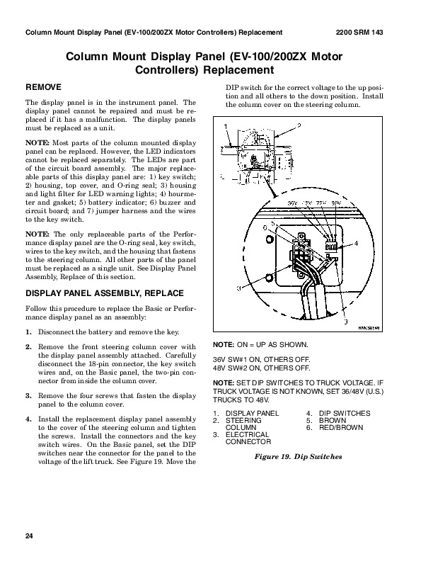
    Cluster-Type Display Panel (Internal Combustion) Replacement…………….1070
      Remove and Disassemble…………….1070
      Assemble and Install…………….1073
    Cluster Display Panel (Electric Lift Truck) Replacement…………….1075
      Display Panel Assembly, Replace…………….1075
      LED Indicators…………….1075
      Battery Indicators…………….1076
      Digital Display (Enhanced Display Panel Only)…………….1076
      Status Code or Performance Level Switches and LED indicators (En…………….1076
      Standard Display Panel Parts, Replace…………….1076
      Enhanced Display Panel Parts, Replace…………….1077
    Curtis 1215 Display Panel Replacement…………….1077
      Remove…………….1077
      Install…………….1077
  tables…………….1055
    Table 1. Instrument Cluster, Internal Combustion…………….1059
hyster-897506-11-03-srm0521…………….1097
  toc…………….1097
    Mast…………….1097
    Safety Precautions Maintenance and Repair…………….1098
    General…………….1101
    Description and Operation…………….1101
      Carriages…………….1101
      Mast Mounts…………….1103
    Two-Stage Mast, Limited Free-Lift (LFL)…………….1104
      Description and Operation…………….1104
    Two-Stage Mast, Full Free-Lift (FFL)…………….1106
      Description and Operation…………….1106
    Three-Stage Mast, Full Free-Lift (FFL)…………….1108
      Description and Operation…………….1108
    Cylinder Cushion During Lifting Sequence…………….1111
    Cylinder Cushion During Lowering Sequence…………….1112
hyster-897507-11-03-srm0522…………….1115
  toc…………….1115
    Mast…………….1115
    Safety Precautions Maintenance and Repair…………….1116
    General…………….1119
    Safety Procedures When Working Near Mast…………….1119
    Forks Repair…………….1121
      Remove…………….1121
      Install…………….1121
    Carriages Repair…………….1122
      Standard Carriage, Remove…………….1122
      Hang-On Sideshift Carriage, Remove…………….1123
      Standard Carriage and Hang-On Sideshift Carriage, Repair…………….1124
      Standard Carriage, Install…………….1124
      Hang-On Sideshift Carriage, Install…………….1125
      Integral Sideshift Carriage…………….1125
        Remove…………….1125
        Clean and Inspect…………….1127
        Repair…………….1127
        Install…………….1128
    Mast Repair…………….1128
      Remove…………….1128
      Two-Stage LFL and Two-Stage FFL Masts, Disassemble…………….1130
      Three-Stage FFL Mast…………….1137
        Disassemble…………….1137
        Mast and Chains, Clean and Inspect…………….1141
      Two-Stage LFL and Two-Stage FFL Mast, Assemble…………….1142
      Three-Stage FFL Mast, Assemble…………….1143
      Install…………….1144
    Lift Cylinders Repair…………….1145
      Main Lift Cylinders, Remove…………….1145
      Free-Lift Cylinder, Remove…………….1146
      Lift Cylinders, Disassemble…………….1146
      Lift Cylinders, Assemble…………….1149
      Main Lift Cylinders, Install…………….1150
      Free-Lift Cylinder, Install…………….1150
    Header Hose Arrangements…………….1151
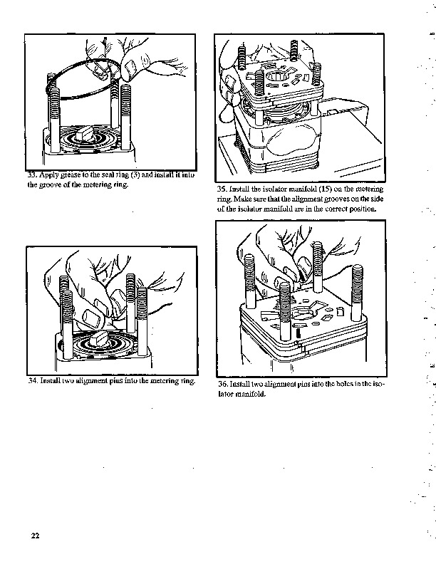
      Two-Stage LFL Mast, New Hose Install…………….1151
      Two-Stage LFL Mast, Adjust Hoses After Installation…………….1156
      Two-Stage FFL Mast, New Hose Install…………….1157
      Two-Stage FFL Mast, Adjust Hoses After Installation…………….1163
      Three-Stage FFL Mast, New Hose Install…………….1163
      Three-Stage FFL Mast, Adjust Hoses After Installation…………….1174
    Header Hose Arrangement…………….1175
      Two-Stage LFL Mast, New Hose Install…………….1175
      Two-Stage LFL Mast, Adjust Hoses After Installation…………….1179
      Two-Stage FFL Mast, New Hose Install…………….1179
      Two-Stage FFL Mast, Adjust Hoses After Installation…………….1184
      Three-Stage FFL Mast, New Hose Install…………….1186
      Three-Stage FFL Mast, Adjust Hoses After Install…………….1194
    Lift and Tilt System Leak Check…………….1195
      Lift Cylinders Leak Check…………….1195
      Tilt Cylinders Leak Check…………….1195
    Tilt Cylinders Adjustment…………….1196
    Lift Chains Adjustment…………….1197
    Mast Adjustment…………….1199
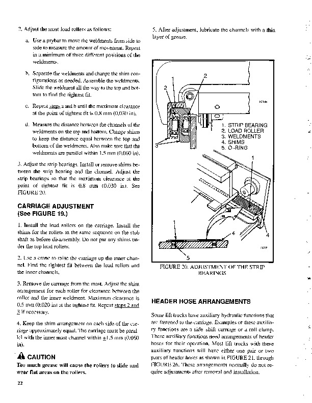
    Carriage Adjustment…………….1201
    Troubleshooting…………….1201
  tables…………….1115
    Table 1. Hook-Type Carriage Chain Adjustment…………….1198
    Table 2. Pin-Type Carriage Chain Adjustment…………….1198
    Electrical System…………….1233
    Safety Precautions Maintenance and Repair…………….1234
    General…………….1237
    Description…………….1237
      Starting System…………….1237
      Ignition System…………….1237
      Charging System…………….1238
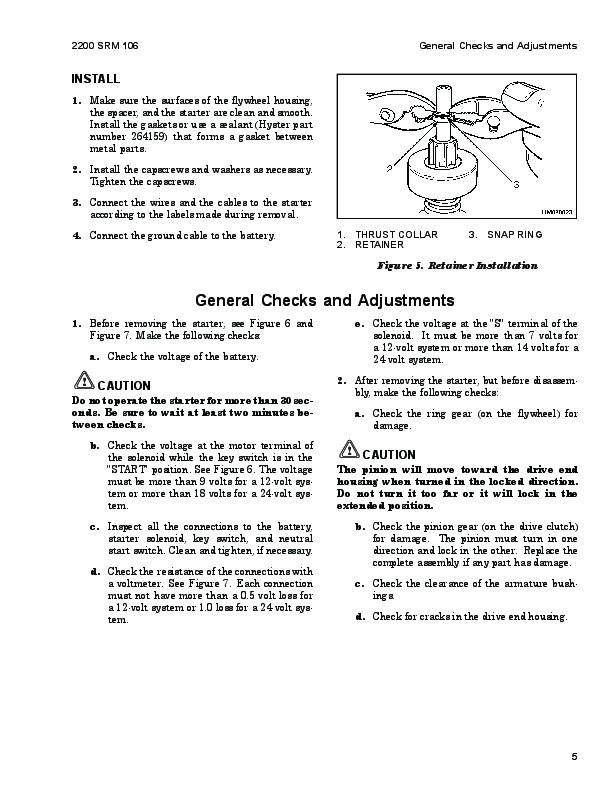
    Starter Repair…………….1239
      Remove and Disassemble…………….1239
      Assemble and Install…………….1239
    Coil Replacement…………….1241
    Distributor Repair H1.50-1.75XM, H2.00XMS (S/H25-35XM, S/H40XMS)…………….1242
      Remove and Disassemble…………….1242
      Assemble and Install…………….1242
    Distributor Repair S/H2.00-3.20XM (S/H40-65XM)…………….1244
      Remove and Disassemble…………….1244
      Assemble and Install…………….1246
    Alternator Repair…………….1246
      Remove and Disassemble…………….1246
      Assemble and Install…………….1248
    General Checks and Adjustments…………….1248
    Starter Checks…………….1248
      Operation, Check…………….1248
      Brush Holder, Check…………….1249
      Armature, Check…………….1249
      Field Windings, Check…………….1249
      Clutch and Bearing, Check…………….1250
    Ignition System Check and Adjustment…………….1250
      Engine Timing, Adjust…………….1250
      Spark Plugs, Check…………….1251
    Charging Circuit Checks…………….1251
      Low Output, Check…………….1251
      High Output, Check…………….1252
      Diodes, Check…………….1252
      Rotor Field Winding, Check…………….1253
      Stator Windings, Check…………….1253
      Brushes and Bearings, Check…………….1254
      Voltage Regulator, Check…………….1254
    Troubleshooting…………….1254
    Alternator with Regulator…………….1439
    Safety Precautions Maintenance and Repair…………….1440
    General…………….1443
    Description…………….1443
    Alternator Repair…………….1445
      Alternator Type A…………….1445
        Remove and Disassemble…………….1445
        Clean…………….1446
        Assemble…………….1447
        Install…………….1447
      Alternator Type B…………….1450
        Remove and Disassemble…………….1450
        Clean…………….1450
        Assemble…………….1451
        Install…………….1452
    General Check and Adjustment…………….1453
    Low Output Check (Type A or Type B)…………….1453
    High Output Check (Type A or Type B)…………….1455
    Brushes Circuit Check…………….1456
      Delco Alternators…………….1456
      Motorola Alternators…………….1457
    Diodes Check…………….1458
    Diode Bridge Check…………….1458
      Delco and Leece-Neville Alternators…………….1458
      Motorola Alternators…………….1458
    Rotor Field Winding Check…………….1459
    Stator Windings Check…………….1460
    Voltage Regulator Check…………….1460
    Troubleshooting…………….1460
hyster-899788-03-02-srm0107…………….1465
  toc…………….1465
    High Energy Ignition (HEI) System…………….1465
    Safety Precautions Maintenance and Repair…………….1466
    Description…………….1469
    Distributor Repair…………….1471
      Remove…………….1471
      Disassemble…………….1471
      Assemble…………….1476
      Install, If Crankshaft WAS NOT Rotated when Distributor was Remo…………….1477
      Install, If Crankshaft WAS Rotated when Distributor was Removed…………….1477
    Ignition Coil Replacement…………….1478
      Some Four- and Six-Cylinder Models…………….1478
        Remove…………….1478
        Install…………….1479
      V8, Some Four- and Six-Cylinder Models…………….1479
        Remove…………….1479
        Install…………….1480
    Electronic Module Replacement…………….1481
      Remove…………….1481
      Install…………….1481
    Sensing Coil Replacement…………….1482
      Remove…………….1482
      Install…………….1482
    Spark Plugs Replacement…………….1482
      Remove…………….1482
      Install…………….1483
    Visual Check…………….1483
    High Voltage Wires Check…………….1483
    Ignition Coil Check…………….1484
      Coil in Distributor Cap Design…………….1484
      Separate Coil Design…………….1484
      Sensing Coil, Check…………….1485
    Electronic Module Check…………….1485
    Ignition Timing Adjustment…………….1485
    GM V8-366 (6-liter) Ignition System Check…………….1487
    GM V6-LPG (4.3 liter) GM V6-LPG (4.3 liter) Ignition Timing and …………….1487
    Specifications…………….1487
    Troubleshooting…………….1488
hyster-910102-10-03-srm0103…………….1493
  toc…………….1493
    Tilt Cylinders…………….1493
    Safety Precautions Maintenance and Repair…………….1494
    General…………….1497
    Description…………….1497
    Tilt Cylinder Repair…………….1497
      Remove…………….1497
      Disassemble…………….1497
      Clean…………….1497
      Assemble…………….1498
        Tilt Cylinders With O-Ring or Single-Lip Seals…………….1498
        Tilt Cylinders for XM and XMS Models…………….1499
        Tilt Cylinders for H700-800A and Early Model H700-920B…………….1500
      Install…………….1501
        Tilt Cylinders Using Chevron Packing…………….1502
          Install…………….1503
    Tilt Cylinder Leak Check…………….1505
    Tilt Cylinder Stroke and Mast Tilt Angle Adjustment…………….1506
    Torque Specifications…………….1507
      Piston Rod Nut…………….1507
      Retainer…………….1508
    Troubleshooting…………….1510
  tables…………….1493
    Table 1. Movement Rates (Maximum) for Tilt Cylinders…………….1506
hyster-910107-02-01-srm0106…………….1513
  toc…………….1513
    Starter…………….1513
    Safety Precautions Maintenance and Repair…………….1514
    General…………….1517
    Description and Operation…………….1517
    Starter Repair…………….1519
      Remove…………….1519
      Disassemble…………….1519
      Clean…………….1520
      Assemble…………….1520
      Install…………….1521
    General Checks and Adjustments…………….1521
    Troubleshooting…………….1524
hyster-910442-03-03-srm0231…………….1529
  toc…………….1529
    Metric and Inch (SAE) Fasteners…………….1529
    Safety Precautions Maintenance and Repair…………….1530
    General…………….1533
      Threaded Fasteners…………….1533
      Nomenclature, Threads…………….1533
      Strength Identification…………….1534
      Cotter (Split) Pins…………….1534
      Fastener Torque Tables…………….1539
      Conversion Table…………….1541
  tables…………….1529
    Table 1. Bolts and Screws…………….1535
    Table 2. Studs and Nuts…………….1536
    Table 3. Torque Nuts…………….1537
    Table 4. Torque Nuts With Nylon Insert…………….1538
    Table 5. Torque Values for Metric Fasteners*…………….1539
    Table 6. Torque Values for Inch Fasteners*…………….1540
    Table 7. Conversion Table for Metric and English units…………….1541
    Table 8. Cotter Pin Dimensional Data…………….1542
hyster-910460-11-03-srm0258…………….1545
  toc…………….1545
    Steering Axle…………….1545
    Safety Precautions Maintenance and Repair…………….1546
    General…………….1549
    Description…………….1549
    Steering Axle Assembly Repair…………….1550
      Remove…………….1550
      Install…………….1550
    Wheels Repair…………….1551
      Remove and Disassemble…………….1551
      Clean…………….1552
      Inspect…………….1552
      Assemble and Install…………….1552
    Spindles, Bearings, and Tie Rods Repair…………….1553
      Remove and Disassemble…………….1553
      Assemble and Install…………….1553
    Steering Cylinder Repair…………….1555
      Remove and Disassemble…………….1555
      Clean and Inspect…………….1555
      Assemble and Install…………….1555
    Torque Specifications…………….1556
    Troubleshooting…………….1556

Hyster S40-65XM (D187) Repair Service Manual


INSTANT DOWNLOAD


Posted on

Hyster H25-35XM, H40XMS (D001) Repair Service Manual


INSTANT DOWNLOAD


Complete service repair manual for Hyster H25-35XM, H40XMS (D001) Forklifts Trucks, with all the technical information to maintain, diagnose, repair,  and rebuild like professional mechanics.

Hyster H25XM, H35XM, H40XMS (D001) workshop service & repair manual includes:
* Numbered table of contents easy to use so that you can find the information you need fast.
* Detailed sub-steps expand on repair procedure information
* Numbered instructions guide you through every repair procedure step by step.
* Troubleshooting and electrical service procedures are combined with detailed wiring diagrams for ease of use.
* Notes, cautions and warnings throughout each chapter pinpoint critical information.
* Bold figure number help you quickly match illustrations with instructions.
* Detailed illustrations, drawings and photos guide you through every procedure.
* Enlarged inset helps you identify and examine parts in detail.

897595 – Hyster H25-35XM, H40XMS (D001) Service Manual.pdf

Total Pages: 685 pages
File Format: PDF (Internal Links, Bookmarked, Table of Contents, Searchable, Printable, high quality)
Language: English

 
Section
Part No.
SRM Number Rev Date
FRAME
897559
  0100 SRM 0545
02/01
MAZDA M4-2.0G ENGINE
897477
  0600 SRM 0496
02/01
MAZDA M4-2.5D ENGINE
897551
  0600 SRM 0538
02/01
COOLING SYSTEM
897934
  0700 SRM 0626
11/01
LPG FUEL SYSTEM (EXCEPT AISAN SYSTEM)
897508
  0900 SRM 0523
01/96
GASOLINE FUEL SYSTEM
897591
  0900 SRM 0547
02/01
LPG FUEL SYSTEM (AISAN SYSTEM)
1488917
  0900 SRM 0925
08/02
SINGLE-SPEED PS TRANS – DESCR/OPER/REPAIR
897557
1300 SRM 0543
12/03
DRIVE AXLE
897556
1400 SRM 0542
12/03
STEERING CONTROL UNIT (ROSS HGF)
910458
1600 SRM 0257
07/00
STEERING AXLE
897545
1600 SRM 0532
02/01
STEERING HOUSING
897649
1600 SRM 0565
 11/94
BRAKE SYSTEM
897554
1800 SRM 0540
02/01
HYDRAULIC SYSTEM and GEAR PUMP
897553
1900 SRM 0539
02/01
MAIN CONTROL VALVE
897555
2000 SRM 0541
02/01
TILT CYLINDERS
910102
2100 SRM 0103
10/03
INSTRUMENT CLUSTER
897495
2200 SRM 0514
01/04
ELECTRICAL SYSTEM  (MAZDA M4-2.0G)
897509
2200 SRM 0524
02/01
ELECTRICAL SYSTEM  (MAZDA M4-2.5D)
897594
2200 SRM 0550
02/01
MAST – DESCRIPTION
897506
4000 SRM 0521
11/03
MAST – REPAIR
897507
4000 SRM 0522
11/03
INCH (SAE) and METRIC FASTENERS
910442
8000 SRM 0231
03/03
PERIODIC MAINTENANCE
1459331
8000 SRM 0531
06/00
DIAGRAMS
897558
8000 SRM 0544
01/03
CAPACITIES and SPECIFICATIONS
897590
8000 SRM 0546
02/01
 
PART NO. 897595
Rev. 01/04


    LPG Fuel System…50
    Safety Precautions Maintenance and Repair…51
    General…54
    Description and Operation…54
      Fuel Tank…55
      Regulator…55
        Start Mode…57
        Idle Mode…57
        Run Mode…57
      Resonator…57
      Carburetor…58
        Start Mode…58
        Idle Mode…58
        Run Mode…58
        Governor…59
    Hoses Replacement…60
    LPG Tank Repair…60
      Remove…60
      Install…61
    Relief Valve Repair…61
      Remove and Install…61
    Carburetor Repair…61
      Remove…61
      Disassemble…61
      Clean…62
      Assemble…63
      Install…63
    Governor Repair…63
      Remove…63
      Inspect…63
      Install…63
    Regulator Repair…64
      Remove…64
      Disassemble…64
      Clean…64
      Inspect…64
      Assemble…66
      Install…67
    Regulator Adjustment…67
      Regulator Height Adjustment…67
      Regulator Assembly Air Tightness Test…68
    Carburetor Adjustment…69
      Idle Speed and Fuel Mixture…69
      Idle Control Adjustment…69
    Governor Adjustment…70
      Checks…70
      Adjustments…70
    Throttle Linkage Adjustment S/H2.00-3.20XM (S/H40-65XM)…71
    MONOTROL® Pedal Check…72
    Throttle Linkage Adjustment S/H1.50-2.00XMS (S/H25-40XMS)…73
    Troubleshooting…74
  tables…50
    Table 1. Power Adjusting Screw…63
    Table 2. Air Adjusting Screw…63
    Table 3. Idle Mixture Adjusting Screw…66
    Table 4. Idle Mixture Adjusting Screw…69
hyster-897477-02-01-srm0496…82
  toc…82
    Mazda Engine…82
    Safety Precautions Maintenance and Repair…83
    General…86
    Description…86
    Engine Removal and Installation…86
    Cylinder Head, Camshaft, and Valve Mechanism Repair…87
      Remove…87
      Clean…88
      Inspect and Repair…89
        Cylinder Head…89
        Rocker Shaft Assembly…89
        Camshaft…89
        Valve Guides…90
        Valve Seats…91
        Valves…91
        Valve Springs…92
      Install…92
    Crankshaft and Main Bearings Repair…95
      Remove…95
      Inspect and Repair…95
        Crankshaft…95
        Main Bearings…95
      Install…96
    Pistons and Connecting Rods Repair…97
      Remove and Disassemble…97
      Clean…97
      Inspect and Repair…97
        Pistons…97
        Piston Rings…97
        Connecting Rods and Bearings…98
      Assemble and Install…98
    Cylinder Block Repair…100
    Oil Pump Repair…100
      Remove…100
      Disassemble…101
      Clean…101
      Inspect…102
      Assemble…102
      Install…103
    Cooling System Repair…103
      Thermostat…103
        Replace…103
      Fan Assembly…103
        Remove and Disassemble…103
        Assemble and Install…104
      Water Pump…104
        Remove and Disassemble…104
        Assemble and Install…105
    Distributor Repair…106
      Remove…106
      Install…106
    Flywheel and Ring Gear Repair S/H2.00-3.20XM (S/H40-65XM)…107
      Remove…107
      Ring Gear, Replace…107
      Install…107
    Flywheel Repair H1.50-175XM, H2.00XMS (S/H25-35XM, S/H40XMS)…108
      Remove…108
      Install…108
    Valve Adjustment…109
    Compression Pressure Check…110
    Engine Timing Adjustment…110
    Throttle Linkage Adjustment…111
      Gasoline Engines…111
      LPG Engines (IMPCO)…111
      LPG Engines (AISAN)…111
    Engine Specifications…111
      Engine Data…111
      Thermostat…111
      Cylinder Head…111
      Valve Mechanism…112
      Camshaft…112
      Crankshaft…112
      Connecting Rods…113
      Cylinder Block…113
      Pistons…113
      Oil Pump…113
    Torque Specifications…114
    Troubleshooting…115
hyster-897495-01-04-srm0514…120
  toc…120
    Instrument Cluster…120
    Safety Precautions Maintenance and Repair…121
    General…124
    Description…124
      Display Panels on Steering Column, Internal Combustion…124
      Display Panels on Steering Column, Electric Lift Trucks…129
        Standard Display Panel…129
        Enhanced Display Panel…130
      Curtis 1215 Display Panel…134
        Description and Features…134
        Operation…134
    Cluster-Type Display Panel (Internal Combustion) Replacement…135
      Remove and Disassemble…135
      Assemble and Install…138
    Cluster Display Panel (Electric Lift Truck) Replacement…140
      Display Panel Assembly, Replace…140
      LED Indicators…140
      Battery Indicators…141
      Digital Display (Enhanced Display Panel Only)…141
      Status Code or Performance Level Switches and LED indicators (En…141
      Standard Display Panel Parts, Replace…141
      Enhanced Display Panel Parts, Replace…142
    Curtis 1215 Display Panel Replacement…142
      Remove…142
      Install…142
  tables…120
    Table 1. Instrument Cluster, Internal Combustion…124
hyster-897506-11-03-srm0521…146
  toc…146
    Mast…146
    Safety Precautions Maintenance and Repair…147
    General…150
    Description and Operation…150
      Carriages…150
      Mast Mounts…152
    Two-Stage Mast, Limited Free-Lift (LFL)…153
      Description and Operation…153
    Two-Stage Mast, Full Free-Lift (FFL)…155
      Description and Operation…155
    Three-Stage Mast, Full Free-Lift (FFL)…157
      Description and Operation…157
    Cylinder Cushion During Lifting Sequence…160
    Cylinder Cushion During Lowering Sequence…161
    Mast…164
    Safety Precautions Maintenance and Repair…165
    General…168
    Safety Procedures When Working Near Mast…168
    Forks Repair…170
      Remove…170
      Install…170
    Carriages Repair…171
      Standard Carriage, Remove…171
      Hang-On Sideshift Carriage, Remove…172
      Standard Carriage and Hang-On Sideshift Carriage, Repair…173
      Standard Carriage, Install…173
      Hang-On Sideshift Carriage, Install…174
      Integral Sideshift Carriage…174
        Remove…174
        Clean and Inspect…176
        Repair…176
        Install…177
    Mast Repair…177
      Remove…177
      Two-Stage LFL and Two-Stage FFL Masts, Disassemble…179
      Three-Stage FFL Mast…186
        Disassemble…186
        Mast and Chains, Clean and Inspect…190
      Two-Stage LFL and Two-Stage FFL Mast, Assemble…191
      Three-Stage FFL Mast, Assemble…192
      Install…193
    Lift Cylinders Repair…194
      Main Lift Cylinders, Remove…194
      Free-Lift Cylinder, Remove…195
      Lift Cylinders, Disassemble…195
      Lift Cylinders, Assemble…198
      Main Lift Cylinders, Install…199
      Free-Lift Cylinder, Install…199
    Header Hose Arrangements…200
      Two-Stage LFL Mast, New Hose Install…200
      Two-Stage LFL Mast, Adjust Hoses After Installation…205
      Two-Stage FFL Mast, New Hose Install…206
      Two-Stage FFL Mast, Adjust Hoses After Installation…212
      Three-Stage FFL Mast, New Hose Install…212
      Three-Stage FFL Mast, Adjust Hoses After Installation…223
    Header Hose Arrangement…224
      Two-Stage LFL Mast, New Hose Install…224
      Two-Stage LFL Mast, Adjust Hoses After Installation…228
      Two-Stage FFL Mast, New Hose Install…228
      Two-Stage FFL Mast, Adjust Hoses After Installation…233
      Three-Stage FFL Mast, New Hose Install…235
      Three-Stage FFL Mast, Adjust Hoses After Install…243
    Lift and Tilt System Leak Check…244
      Lift Cylinders Leak Check…244
      Tilt Cylinders Leak Check…244
    Tilt Cylinders Adjustment…245
    Lift Chains Adjustment…246
    Mast Adjustment…248
    Carriage Adjustment…250
    Troubleshooting…250
  tables…164
    Table 1. Hook-Type Carriage Chain Adjustment…247
    Table 2. Pin-Type Carriage Chain Adjustment…247
    Electrical System…282
    Safety Precautions Maintenance and Repair…283
    General…286
    Description…286
      Starting System…286
      Ignition System…286
      Charging System…287
    Starter Repair…288
      Remove and Disassemble…288
      Assemble and Install…288
    Coil Replacement…290
    Distributor Repair H1.50-1.75XM, H2.00XMS (S/H25-35XM, S/H40XMS)…291
      Remove and Disassemble…291
      Assemble and Install…291
    Distributor Repair S/H2.00-3.20XM (S/H40-65XM)…293
      Remove and Disassemble…293
      Assemble and Install…295
    Alternator Repair…295
      Remove and Disassemble…295
      Assemble and Install…297
    General Checks and Adjustments…297
    Starter Checks…297
      Operation, Check…297
      Brush Holder, Check…298
      Armature, Check…298
      Field Windings, Check…298
      Clutch and Bearing, Check…299
    Ignition System Check and Adjustment…299
      Engine Timing, Adjust…299
      Spark Plugs, Check…300
    Charging Circuit Checks…300
      Low Output, Check…300
      High Output, Check…301
      Diodes, Check…301
      Rotor Field Winding, Check…302
      Stator Windings, Check…302
      Brushes and Bearings, Check…303
      Voltage Regulator, Check…303
    Troubleshooting…303
hyster-897545-02-01-srm0532…308
  toc…308
    Steering Axle…308
    Safety Precautions Maintenance and Repair…309
    General…312
    Description…312
    Steering Axle Assembly Repair…313
      Remove…313
      Install…313
    Wheels and Hubs Repair…313
      Pneumatic Tires, Remove and Disassemble…313
      Cushion Tires, Remove and Disassemble…315
      Pneumatic Tires, Assemble and Install…315
      Cushion Tires, Assemble and Install…315
    Spindles, Bearings, and Tie Rods Repair…316
      Pneumatic Tires, Remove…316
      Cushion Tires, Remove…316
      Pneumatic Tires, Install…316
      Cushion Tires, Install…317
    Steering Cylinder Repair…317
      Remove and Disassemble…317
      Clean and Inspect…317
      Assemble and Install…317
    Torque Specifications…318
    Troubleshooting…319
hyster-897551-02-01-srm0538…322
  toc…322
    Mazda Engine…322
    Safety Precautions Maintenance and Repair…323
    General…326
    Description…326
    Engine Removal and Installation…327
    Cylinder Head and Valve Mechanism Repair…327
      Remove…327
      Clean…328
      Inspect and Repair…328
        Cylinder Head…328
        Rocker Shaft Assembly…328
        Valve Guides…329
        Valve Seats…329
        Valves…329
        Valve Springs…330
        Push Rods…331
      Cylinder Head…331
        Assemble…331
        Install…331
    Timing Gears Repair…333
      Remove…333
      Clean and Inspect…333
      Install…333
    Crankshaft and Main Bearings Repair…335
      Remove…335
      Inspect and Repair…335
        Crankshaft…335
        Main Bearings…336
      Install…336
    Pistons and Connecting Rods Repair…336
      Remove and Disassemble…336
      Clean…337
      Inspect and Repair…337
        Pistons…337
        Piston Rings…337
        Connecting Rods and Bearings…337
      Assemble and Install…338
    Cylinder Block and Liners Repair…339
      Inspect and Repair…339
    Lubrication System Repair…341
      Oil Pump…341
        Remove…341
        Disassemble…341
        Clean…341
        Inspect…341
        Assemble…343
        Install…343
      Oil Filter Mount…343
        Remove…343
        Install…343
    Cooling System Repair…344
      Thermostat…344
        Remove and Install…344
      Water Pump…344
        Remove…344
        Disassemble…344
        Inspect…345
        Assemble…345
        Install…346
    Fuel System Description and Operation…346
    Fuel Injection Pump Repair…348
      Remove…348
      Install…349
    Fuel Filter Repair…349
      New Filter, Install…349
      Water Sensor, Check…349
    Fuel System Air Removal…350
    Fuel Injectors Repair…351
      Remove and Disassemble…351
      Assemble…351
      Inspect and Adjust…351
      Install…352
    Flywheel Repair…353
      Remove…353
      Install…353
    Valves Adjustment…354
    Compression Pressure Check…354
    Throttle Linkage Adjustment…355
    Fuel Injection Pump Timing Check…355
    Engine Specifications…356
      Engine Model M4-2.5D…356
    Torque Specifications…357
    Troubleshooting…358
  tables…322
    Table 1. Crankshaft Journal Diameters…335
hyster-897553-02-01-srm0539…366
  toc…366
    Hydraulic System and Gear Pump Assembly…366
    Safety Precautions Maintenance and Repair…367
    General…370
    Description and Operation…370
      Hydraulic System…370
      Gear Pump Assembly…372
      Pump Drive Shaft…374
      Steering Flow Divider…375
      Relief Valve (Steering)…375
      Relief Valve (Main Hydraulic)…376
    Gear Pump Assembly Repair…377
      Remove and Disassemble…377
      Assemble and Install…377
    Pump Drive Shaft Repair…377
      Disassemble…377
      Assemble and Install…378
    Steering Relief Pressure Check and Adjust…378
    Gear Pump Flow Check…378
    Troubleshooting…379
    Brake System…384
    Safety Precautions Maintenance and Repair…385
    General…388
    Description and Operation…388
      Service Brake…388
      Parking Brake…389
    Service Brakes Repair…389
      Remove and Disassemble…389
      Clean…392
      Inspect…392
      Assemble and Install…393
      Adjust…395
    Parking Brake Repair…396
      Remove and Disassemble…396
      Assemble and Install…397
      Adjust…397
    Master Cylinder Repair…397
      Remove…397
      Disassemble…397
      Clean and Inspect…397
      Assemble…399
      Install…399
    Service Brakes Adjustment…399
    Brake System Air Removal…400
    Parking Brake Not Applied Switch Test…400
    Parking Brake Switch Test (MONOTROL® Pedal Only)…400
    Inching/Brake Pedal Adjustment…401
    Torque Specifications…401
    Troubleshooting…403
    Main Control Valve…408
    Safety Precautions Maintenance and Repair…409
    General…412
    Description…412
    Operation…413
      Lift Section…414
      Tilt Section…414
        Tilt Backward…414
        Tilt Forward…414
      Steering Flow Divider…417
      Relief Valve (Steering)…417
      Relief Valve (Main Hydraulic)…417
    Main Control Valve Repair…418
      Remove…418
      Disassemble…418
      Clean and Inspect…418
      Assemble…418
      Install…418
    Pressure Relief Valve Check and Adjustment…425
      Steering Relief Valve…425
      Main Hydraulic Relief Valve…425
    Troubleshooting…426
    Drive Axle…430
    Safety Precautions Maintenance and Repair…431
    General…434
    Description…435
    Drive Axle Repair…435
      Remove and Disassemble…435
      Clean and Inspect…436
      Assemble and Install…436
    Torque Specifications…438
    Troubleshooting…438
    Single-Speed Powershift Transmission…442
    Safety Precautions Maintenance and Repair…443
    General…446
    Torque Converter Description and Operation…447
      Description…447
      Operation…447
    Clutch Assemblies Description and Operation…449
      Description…449
      Operation…450
    Hydraulic System Operation…451
    Control Valve Operation…453
      Regulator for Clutch Pressure…453
      Inching Spool Assembly…453
      Direction Spool…453
      Modulator Circuit…453
      Regulator for the Torque Converter…453
    MONOTROL® Pedal Operation…454
    Direction Control Lever Operation…454
    Differential Operation…454
    Torque Converter and Transmission Pump Repair…454
      Remove and Disassemble…454
      Inspect…455
      Assemble and Install…455
    Clutch Assemblies Repair…456
      Remove and Disassemble…456
      Inspect…459
      Assemble and Install…459
    Differential Repair…460
      Remove and Disassemble…460
      Inspect…460
      Assemble and Install…460
        New Ring and Pinion Assembly, Install…461
        Pinion Assembly, Install…464
        Differential and Ring Gear Assembly, Assemble…465
    Control Valve Repair…466
      Remove…466
      Disassemble, Earlier Models…466
      Disassemble, Later Models…467
      Inspect…467
      Assemble, Earlier Models…467
      Assemble, Later Models…468
      Install…468
    MONOTROL® Pedal Repair…469
      Remove and Disassemble…469
      Assemble and Install…469
    Direction Control Lever Repair…472
      Remove and Disassemble…472
      Assemble and Install…472
    Torque Converter Stall Test…473
    Transmission Pressure Tests…474
      Transmission Pump Pressure Check, Test Port No. 1…475
      Torque Converter Inlet Pressure Check, Test Port No. 2…475
      Clutch Pressure Check, Test Port No. 3…475
    Inching/Brake Pedal Adjustment…475
    Troubleshooting…475
  tables…442
    Table 1. Pinion Assembly Shims Adjustment…462
    Table 2. Ring and Pinion Tooth Contact Adjustment…463
    Table 3. Stall Speeds…474
    Table 4. Pressure Test Ports…474
hyster-897558-01-03-srm0544…484
  toc…484
    Diagrams…484
    Safety Precautions Maintenance and Repair…485
hyster-897559-02-01-srm0545…514
  toc…514
    Frame…514
    Safety Precautions Maintenance and Repair…515
    General…518
    Description…518
    Operator Module Repair…518
      Remove…518
      Install…519
    Hood and Side Covers Repair…520
      Remove…520
      Install…520
    Overhead Guard Repair…522
      Remove and Install…522
    Counterweight Repair…523
      Remove…523
      Install…524
    Exhaust System Repair…525
      Muffler, Replace…525
    Radiator and Cooling System Repair…529
      Remove…529
      Install…529
    Operator Restraint System Repair…530
    Engine Repair…531
      Remove (Engine Only)…531
      Remove (Engine and Transmission)…531
      Install (Engine Only)…531
      Install (Engine and Transmission)…532
    Fuel and Hydraulic Tanks Repair…533
      Clean…533
        Steam Method of Cleaning…533
        Chemical Solution Method of Cleaning…533
      Inspect…533
      Repair…533
        Small Leaks…533
        Large Leaks…534
    Safety Labels…534
  tables…514
    Table 1. Weight of Counterweights…523
hyster-897590-02-01-srm0546…540
  toc…540
    Capacities and Specifications…540
    Safety Precautions Maintenance and Repair…541
    Engine Specifications…544
    Electrical System…544
    Hydraulic System…545
    Lift Truck Weights…545
    Torque Converter Stall Speeds…545
    Tire Pressure…546
    Capacities…546
    Mast Speeds…547
      Mazda M4-1.5G Engine Mast Speeds…547
      Mazda M4-2.0G Engine Mast Speeds…547
      Mazda M4-2.5D Engine Mast Speeds…548
    Transmission Oil Pressures…548
    Torque Specifications…549
      Brake System…549
      Drive Axle…549
      Engine – Mazda M4-1.5G…549
      Engine – Mazda M4-2.0G…549
      Engine – Mazda M4-2.5D…550
      Frame…551
      Mast…551
      Steering System…551
      Transmission and Differential…551
hyster-897591-02-01-srm0547…554
  toc…554
    Gasoline Fuel System…554
    Safety Precautions Maintenance and Repair…555
    Description…558
      Governor…558
    Carburetor Repair…559
      Remove…559
      Disassemble…561
      Clean…563
      Inspect…563
      Assemble…564
      Install…567
    Carburetor Checks and Adjustments…567
      Idle Speed and Mixture, Adjust…567
      Throttle Linkage, Adjust…567
    Governor Checks and Adjustments…569
    Troubleshooting…570
hyster-897594-02-01-srm0550…576
  toc…576
    Electrical System…576
    Safety Precautions Maintenance and Repair…577
    General…580
    Description…580
      Starting Circuit…580
      Charging System…581
    Starter Repair…582
      Remove and Disassemble…582
      Assemble and Install…582
    Alternator Repair…584
      Remove and Disassemble…584
      Assemble and Install…585
    General Checks and Adjustments…586
    Starter Checks…586
      Operation Check…586
      Solenoid Coil Checks…587
      Brush Holder Check…587
      Armature Check…587
      Field Windings Check…587
      Clutch and Bearing Check…587
    Cold Start Aid Checks…588
      Glow Plugs…588
      Fuse…588
      Relay and Controller…588
    Charging Circuit Checks…589
      Low-Output Check…589
      High-Output Check…590
      Diodes Check…590
      Rotor Field Winding Check…591
      Stator Windings Check…592
      Brushes and Bearings…592
      Voltage Regulator Check…592
    Troubleshooting…593
hyster-897649-11-94-srm0565…598
  …598
  …599
  …600
  …601
  …602
  …603
  …604
  …605
hyster-897934-11-01-srm0626…606
  toc…606
    Cooling System…606
    Safety Precautions Maintenance and Repair…607
    General…610
    Description…611
      Radiator…611
      Radiator Cap…611
      Thermostat…611
      Water Pump…612
      Fan and Fan Shroud…612
    Cooling System Checks…612
      Radiator…612
      Thermostat…612
      Water Pump…613
      Exhaust Leaks…613
      Fan and Fan Shroud…613
    Radiator Cleaning…613
      Drain…613
      Clean…613
      Fill…614
    Troubleshooting…615
hyster-910102-10-03-srm0103…618
  toc…618
    Tilt Cylinders…618
    Safety Precautions Maintenance and Repair…619
    General…622
    Description…622
    Tilt Cylinder Repair…622
      Remove…622
      Disassemble…622
      Clean…622
      Assemble…623
        Tilt Cylinders With O-Ring or Single-Lip Seals…623
        Tilt Cylinders for XM and XMS Models…624
        Tilt Cylinders for H700-800A and Early Model H700-920B…625
      Install…626
        Tilt Cylinders Using Chevron Packing…627
          Install…628
    Tilt Cylinder Leak Check…630
    Tilt Cylinder Stroke and Mast Tilt Angle Adjustment…631
    Torque Specifications…632
      Piston Rod Nut…632
      Retainer…633
    Troubleshooting…635
  tables…618
    Table 1. Movement Rates (Maximum) for Tilt Cylinders…631
hyster-910442-03-03-srm0231…638
  toc…638
    Metric and Inch (SAE) Fasteners…638
    Safety Precautions Maintenance and Repair…639
    General…642
      Threaded Fasteners…642
      Nomenclature, Threads…642
      Strength Identification…643
      Cotter (Split) Pins…643
      Fastener Torque Tables…648
      Conversion Table…650
  tables…638
    Table 1. Bolts and Screws…644
    Table 2. Studs and Nuts…645
    Table 3. Torque Nuts…646
    Table 4. Torque Nuts With Nylon Insert…647
    Table 5. Torque Values for Metric Fasteners*…648
    Table 6. Torque Values for Inch Fasteners*…649
    Table 7. Conversion Table for Metric and English units…650
    Table 8. Cotter Pin Dimensional Data…651
hyster-910458-07-00-srm0257…654

Hyster H25-35XM, H40XMS (D001) Repair Service Manual


INSTANT DOWNLOAD


Posted on

Hyster H45-50-55-60-65XM (D177) Repair Service Manual


INSTANT DOWNLOAD


Complete service repair manual for Hyster H45-50-55-60-65XM (D177) Forklifts Trucks, with all the shop information to maintain, diagnose, repair, and rebuild like professional mechanics.

Hyster H45XM, H50XM, H55XM, H60XM, H65XM (D177) workshop service & repair manual includes:
* Numbered table of contents easy to use so that you can find the information you need fast.
* Detailed sub-steps expand on repair procedure information
* Numbered instructions guide you through every repair procedure step by step.
* Troubleshooting and electrical service procedures are combined with detailed wiring diagrams for ease of use.
* Notes, cautions and warnings throughout each chapter pinpoint critical information.
* Bold figure number help you quickly match illustrations with instructions.
* Detailed illustrations, drawings and photos guide you through every procedure.
* Enlarged inset helps you identify and examine parts in detail.

897469 – Hyster H45-50-55-60-65XM (D177) Service Manual.pdf

Total Pages: 1,143 pages
File Format: PDF (Internal Links, Bookmarked, Table of Contents, Searchable, Printable, high quality)
Language: English

 
Section
Part No.
SRM Number
Rev Date
FRAME
897486
 0100 SRM 0505
01/01
GM 3.0L ENGINE
899766
0600 SRM  0003
08/03
ISUZU 4JB1 (2.8L) ENGINE
897418
0600 SRM 0467
04/93
MAZDA M4-2.0G ENGINE
897417
 0600 SRM 0496
02/01
GM 2.2L ENGINE
897478
 0600 SRM 0497
04/93
ISUZU 4JG2 (3.1L) ENGINE
897611
  0600 SRM 0553
11/95
COOLING SYSTEM
897934
  0700 SRM 0626
11/01
LPG FUEL SYSTEM (GM 2.2L AND 3.0L)
897479
  0900 SRM 0498
01/96
GASOLINE FUEL SYSTEM (MAZDA)
897483
  0900 SRM 0502
01/01
LPG FUEL SYSTEM (MAZDA)
897508
  0900 SRM 0523
01/96
SINGLE-SPD POWERSHIFT TRANS-DESCR & OPER
897481
1300 SRM 0500
08/03
SINGLE-SPD POWERSHIFT TRANSMISSION-REPAIR
897482
1300 SRM 0501
08/03
DRIVE AXLE
897480
1400 SRM 0499
01/96
STEERING AXLE
897097
1600 SRM 0316
03/03
STEERING HOUSING AND CONTROL UNIT
897493
1600 SRM 0512
08/03
BRAKE SYSTEM
897487
1800 SRM 0506
01/96
HYDRAULIC SYSTEM and GEAR PUMP
897494
1900 SRM 0513
12/95
MAIN CONTROL VALVE
897497
2000 SRM 0516
11/95
TILT CYLINDERS
910102
2100 SRM 0103
10/03
ALTERNATOR
899784
2200 SRM 0002
09/02
STARTER
910107
2200 SRM 0106
02/01
ELECTRONIC ENGINE CONTROL-REPAIR (GM 2.2L)
897460
2200 SRM 0490
04/93
INSTRUMENT CLUSTER
897495
2200 SRM 0514
01/04
MICROPROCESSOR SPARK TIMING SYSTEM (GM 2.2L)
897496
2200 SRM 0515
04/93
ELECTRICAL SYSTEM (ISUZU)
897505
2200 SRM 0520
05/94
ELECTRICAL SYSTEM (MAZDA)
897509
2200 SRM 0524
02/01
ELECTRONIC ENGINE CONTROL-DESCR/OPER (GM 2.2L)
897516
2200 SRM 0525
04/93
MSTS-GM 3.0L (EARLY CONTROL MODULES)
897844
2200 SRM 0603
01/96
ELECTRONIC ENGINE CONTROL-REPAIR (GM 3.0L)
897855
2200 SRM 0611
02/96
ELECTRONIC ENGINE CONTROL-DESCR/OPER (GM 3.0L)
897856
2200 SRM 0612
01/96
MSTS-GM 3.0L (LATER CONTROL MODULES)
1473385
2200 SRM 0765
11/01
MAST-DESCRIPTION
897506
4000 SRM 0521
11/03
MAST-REPAIR
897507
4000 SRM 0522
11/03
PERIODIC MAINTENANCE
897470
8000 SRM 0493
07/97
CAPACITIES AND SPECIFICATIONS
897484
8000 SRM 0503
08/95
DIAGRAMS
897485
8000 SRM 0504
04/00
 
PART NO. 897469
Rev. 01/04

    Steering Axle…..51
    Safety Precautions Maintenance and Repair…..52
    General…..55
    Description…..55
    Steering Axle Assembly Repair…..56
      Remove…..56
      Install…..56
    Wheels and Hubs Repair…..57
      Remove and Disassemble…..57
      Clean…..57
      Assemble and Install…..57
    Spindles, Bearings, and Tie Rods Repair…..59
      Remove…..59
      Install…..59
    Steering Cylinder Repair…..60
      Remove and Disassemble…..60
      Clean and Inspect…..61
      Assemble and Install…..61
    Torque Specifications…..61
    Troubleshooting…..62
    Mazda Engine…..271
    Safety Precautions Maintenance and Repair…..272
    General…..275
    Description…..275
    Engine Removal and Installation…..275
    Cylinder Head, Camshaft, and Valve Mechanism Repair…..276
      Remove…..276
      Clean…..277
      Inspect and Repair…..278
        Cylinder Head…..278
        Rocker Shaft Assembly…..278
        Camshaft…..278
        Valve Guides…..279
        Valve Seats…..280
        Valves…..280
        Valve Springs…..281
      Install…..281
    Crankshaft and Main Bearings Repair…..284
      Remove…..284
      Inspect and Repair…..284
        Crankshaft…..284
        Main Bearings…..284
      Install…..285
    Pistons and Connecting Rods Repair…..286
      Remove and Disassemble…..286
      Clean…..286
      Inspect and Repair…..286
        Pistons…..286
        Piston Rings…..286
        Connecting Rods and Bearings…..287
      Assemble and Install…..287
    Cylinder Block Repair…..289
    Oil Pump Repair…..289
      Remove…..289
      Disassemble…..290
      Clean…..290
      Inspect…..291
      Assemble…..291
      Install…..292
    Cooling System Repair…..292
      Thermostat…..292
        Replace…..292
      Fan Assembly…..292
        Remove and Disassemble…..292
        Assemble and Install…..293
      Water Pump…..293
        Remove and Disassemble…..293
        Assemble and Install…..294
    Distributor Repair…..295
      Remove…..295
      Install…..295
    Flywheel and Ring Gear Repair S/H2.00-3.20XM (S/H40-65XM)…..296
      Remove…..296
      Ring Gear, Replace…..296
      Install…..296
    Flywheel Repair H1.50-175XM, H2.00XMS (S/H25-35XM, S/H40XMS)…..297
      Remove…..297
      Install…..297
    Valve Adjustment…..298
    Compression Pressure Check…..299
    Engine Timing Adjustment…..299
    Throttle Linkage Adjustment…..300
      Gasoline Engines…..300
      LPG Engines (IMPCO)…..300
      LPG Engines (AISAN)…..300
    Engine Specifications…..300
      Engine Data…..300
      Thermostat…..300
      Cylinder Head…..300
      Valve Mechanism…..301
      Camshaft…..301
      Crankshaft…..301
      Connecting Rods…..302
      Cylinder Block…..302
      Pistons…..302
      Oil Pump…..302
    Torque Specifications…..303
    Troubleshooting…..304
    Single-Speed Powershift Transmission…..377
    Safety Precautions Maintenance and Repair…..378
    General…..381
    Description and Operation…..381
      General…..381
      Torque Converter…..382
        Description…..382
        Operation…..382
      Clutch Assemblies…..384
        Description…..384
        Operation…..385
      Hydraulic System…..388
        General…..388
      Control Valve…..389
        General…..389
        Clutch Pressure Regulator…..390
        Inching Spool Assembly…..391
        Direction Spool…..391
        Modulator Circuit…..391
        Torque Converter Regulator…..391
      MONOTROL® Pedal…..391
        MONOTROL Pedal Start Circuit…..392
      Direction Control Lever…..392
      Differential…..392
    Oil Flow Diagrams…..394
      Neutral…..394
      Modulator Operation…..394
      Forward…..398
      Forward-Inching…..398
hyster-897482-08-03-srm0501…..405
  toc…..405
    Single-Speed Powershift Transmission…..405
    Safety Precautions Maintenance and Repair…..406
    General…..409
    Transmission Removal…..411
    Torque Converter and Housing Repair…..413
      Remove…..413
      Install…..413
    Transmission Pump Repair…..415
      Remove…..415
      Repair…..415
      Install…..415
    Front Cover and Pump Drive Repair…..415
      Remove and Disassemble…..415
      Assemble and Install…..415
    Clutch Assemblies Repair…..418
      Remove and Disassemble…..421
      Inspect…..422
      Assemble…..423
      Install…..428
    Differential Repair…..429
      Remove and Disassemble…..429
      Inspect…..430
      Assemble and Install…..431
    Control Valve Repair…..438
      Remove and Disassemble…..438
      Inspect…..441
      Assemble and Install…..441
    MONOTROL® Pedal Repair…..442
      Remove and Disassemble…..442
      Assemble and Install…..442
    Direction Control Lever Repair…..446
      Remove and Disassemble…..446
      Assemble and Install…..446
    Stall Test…..447
    Inching/Brake Pedal Adjustment…..448
    Neutral Start Switch, MONOTROL Pedal Adjustment H2.00-3.20XM (H4…..452
    Neutral Start Switch, MONOTROL Pedal Adjustment S2.00-3.20XM (S4…..453
    Neutral Start Switch Test, MONOTROL® Pedal…..454
    Oil Pressure Checks…..454
      Relief Valve for Transmission Pump Check, TEST PORT 1…..454
      Clutch Pressure Check, TEST PORTS 2 and 3…..454
      Torque Converter Regulator Check, TEST PORT 4…..455
      Lubrication Circuit Oil Pressure Check, TEST PORT 5…..455
      Modulator Pressure Check, TEST PORT 6…..456
    Troubleshooting…..456
    Troubleshooting – Pressure Tests…..459
  tables…..405
    Table 1. Adjustment of Shims for Pinion Assembly…..432
    Table 2. Ring and Pinion Tooth Contact Adjustment…..433
    Table 3. Stall Speeds…..448
    Table 4. Transmission Oil Pressures Test Ports…..455
    Safety Precautions Maintenance and Repair…..536
    General…..539
    Description…..539
    Operation…..540
    Steering Wheel and Column Assembly Repair…..541
      Steering Column Assembly, Remove…..541
        Steering Control Unit…..546
          Disassemble…..546
          Clean…..549
          Assemble…..550
          Install…..557
      Steering Column Assembly, Install…..559
    System Air Removal…..560
      Remove…..560
    Troubleshooting…..560
        Standard Display Panel…..586
        Enhanced Display Panel…..587
      Curtis 1215 Display Panel…..591
        Description and Features…..591
        Operation…..591
    Cluster-Type Display Panel (Internal Combustion) Replacement…..592
      Remove and Disassemble…..592
      Assemble and Install…..595
    Cluster Display Panel (Electric Lift Truck) Replacement…..597
      Display Panel Assembly, Replace…..597
      LED Indicators…..597
      Battery Indicators…..598
      Digital Display (Enhanced Display Panel Only)…..598
      Status Code or Performance Level Switches and LED indicators (En…..598
      Standard Display Panel Parts, Replace…..598
      Enhanced Display Panel Parts, Replace…..599
    Curtis 1215 Display Panel Replacement…..599
      Remove…..599
      Install…..599
  tables…..577
    Table 1. Instrument Cluster, Internal Combustion…..581
      Mast Mounts…..677
    Two-Stage Mast, Limited Free-Lift (LFL)…..678
      Description and Operation…..678
    Two-Stage Mast, Full Free-Lift (FFL)…..680
      Description and Operation…..680
    Three-Stage Mast, Full Free-Lift (FFL)…..682
      Description and Operation…..682
    Cylinder Cushion During Lifting Sequence…..685
    Cylinder Cushion During Lowering Sequence…..686
hyster-897507-11-03-srm0522…..689
  toc…..689
    Mast…..689
    Safety Precautions Maintenance and Repair…..690
    General…..693
    Safety Procedures When Working Near Mast…..693
    Forks Repair…..695
      Remove…..695
      Install…..695
    Carriages Repair…..696
      Standard Carriage, Remove…..696
      Hang-On Sideshift Carriage, Remove…..697
      Standard Carriage and Hang-On Sideshift Carriage, Repair…..698
      Standard Carriage, Install…..698
      Hang-On Sideshift Carriage, Install…..699
      Integral Sideshift Carriage…..699
        Remove…..699
        Clean and Inspect…..701
        Repair…..701
        Install…..702
    Mast Repair…..702
      Remove…..702
      Two-Stage LFL and Two-Stage FFL Masts, Disassemble…..704
      Three-Stage FFL Mast…..711
        Disassemble…..711
        Mast and Chains, Clean and Inspect…..715
      Two-Stage LFL and Two-Stage FFL Mast, Assemble…..716
      Three-Stage FFL Mast, Assemble…..717
      Install…..718
    Lift Cylinders Repair…..719
      Main Lift Cylinders, Remove…..719
      Free-Lift Cylinder, Remove…..720
      Lift Cylinders, Disassemble…..720
      Lift Cylinders, Assemble…..723
      Main Lift Cylinders, Install…..724
      Free-Lift Cylinder, Install…..724
    Header Hose Arrangements…..725
      Two-Stage LFL Mast, New Hose Install…..725
      Two-Stage LFL Mast, Adjust Hoses After Installation…..730
      Two-Stage FFL Mast, New Hose Install…..731
      Two-Stage FFL Mast, Adjust Hoses After Installation…..737
      Three-Stage FFL Mast, New Hose Install…..737
      Three-Stage FFL Mast, Adjust Hoses After Installation…..748
    Header Hose Arrangement…..749
      Two-Stage LFL Mast, New Hose Install…..749
      Two-Stage LFL Mast, Adjust Hoses After Installation…..753
      Two-Stage FFL Mast, New Hose Install…..753
      Two-Stage FFL Mast, Adjust Hoses After Installation…..758
      Three-Stage FFL Mast, New Hose Install…..760
      Three-Stage FFL Mast, Adjust Hoses After Install…..768
    Lift and Tilt System Leak Check…..769
      Lift Cylinders Leak Check…..769
      Tilt Cylinders Leak Check…..769
    Tilt Cylinders Adjustment…..770
    Lift Chains Adjustment…..771
    Mast Adjustment…..773
    Carriage Adjustment…..775
    Troubleshooting…..775
  tables…..689
    Table 1. Hook-Type Carriage Chain Adjustment…..772
    Table 2. Pin-Type Carriage Chain Adjustment…..772
  toc…..807
    Electrical System…..807
    Safety Precautions Maintenance and Repair…..808
    General…..811
    Description…..811
      Starting System…..811
      Ignition System…..811
      Charging System…..812
    Starter Repair…..813
      Remove and Disassemble…..813
      Assemble and Install…..813
    Coil Replacement…..815
    Distributor Repair H1.50-1.75XM, H2.00XMS (S/H25-35XM, S/H40XMS)…..816
      Remove and Disassemble…..816
      Assemble and Install…..816
    Distributor Repair S/H2.00-3.20XM (S/H40-65XM)…..818
      Remove and Disassemble…..818
      Assemble and Install…..820
    Alternator Repair…..820
      Remove and Disassemble…..820
      Assemble and Install…..822
    General Checks and Adjustments…..822
    Starter Checks…..822
      Operation, Check…..822
      Brush Holder, Check…..823
      Armature, Check…..823
      Field Windings, Check…..823
      Clutch and Bearing, Check…..824
    Ignition System Check and Adjustment…..824
      Engine Timing, Adjust…..824
      Spark Plugs, Check…..825
    Charging Circuit Checks…..825
      Low Output, Check…..825
      High Output, Check…..826
      Diodes, Check…..826
      Rotor Field Winding, Check…..827
      Stator Windings, Check…..827
      Brushes and Bearings, Check…..828
      Voltage Regulator, Check…..828
    Troubleshooting…..828
    General…..1057
    Description…..1058
      Radiator…..1058
      Radiator Cap…..1058
      Thermostat…..1058
      Water Pump…..1059
      Fan and Fan Shroud…..1059
    Cooling System Checks…..1059
      Radiator…..1059
      Thermostat…..1059
      Water Pump…..1060
      Exhaust Leaks…..1060
      Fan and Fan Shroud…..1060
    Radiator Cleaning…..1060
      Drain…..1060
      Clean…..1060
      Fill…..1061
    Troubleshooting…..1062
hyster-899766-08-03-srm0003…..1065
  toc…..1065
    GM Engines…..1065
    Safety Precautions Maintenance and Repair…..1066
    General…..1069
    Description…..1069
    Engine Removal and Installation…..1071
    Cylinder Head and Valve Mechanism Repair…..1071
      Cylinder Head, Remove…..1071
      Cylinder Head, Disassemble…..1071
      Clean and Inspect…..1071
      Valves and Valve Seats…..1074
      Studs for Rocker Arms…..1074
      Hydraulic Valve Lifters, Replace…..1075
      Hydraulic Valve Lifters, Clean and Inspect…..1075
      Cylinder Head, Assemble…..1075
      Cylinder Head, Install…..1075
      Valve Clearance, Adjust…..1076
      Rocker Arm Cover, Install…..1077
    Timing Gear Cover Repair…..1077
      Remove…..1077
      Install…..1078
    Camshaft Repair…..1079
      Remove…..1079
      Inspect…..1079
      Camshaft Bearing…..1080
        Remove…..1080
        Install…..1080
    Distributor Repair…..1081
      Remove…..1081
      Install…..1081
    Lubrication System Repair…..1082
      Oil Sump…..1082
        Remove…..1082
        Install…..1082
      Oil Pump…..1082
        Remove…..1082
        Disassemble and Repair…..1082
        Assemble…..1083
        Install…..1083
    Piston and Connecting Rod Assemblies Repair…..1083
      Connecting Rod Bearings, Replace…..1083
      Piston and Connecting Rod Assemblies, Remove…..1084
      Piston and Connecting Rod Assemblies, Disassemble…..1085
      Piston, Clean and Inspect…..1085
      Cylinder Bores, Inspect and Repair…..1085
      Piston Rings, Inspect…..1086
      Piston and Connecting Rod Assemblies, Assemble…..1086
      Piston and Connecting Rod Assemblies, Install…..1088
    Crankshaft Repair…..1088
      Main Bearings, Replace…..1088
      Oil Seal for Rear Main Bearing, Replace (GM 4-181 and 3.0L Only)…..1089
      Oil Seal for Rear Main Bearing, Replace (Engines That Have Two-P…..1089
      Remove…..1091
      Inspect and Repair…..1091
      Main Bearing and Journal Clearance, Check…..1092
      Install…..1092
    Flywheel and Flywheel Housing Repair…..1093
      Remove…..1094
      Ring Gear, Replace…..1095
      Install…..1095
    Cooling System Repair…..1095
      Coolant Pump…..1095
      Fan Drive…..1095
      Viscous Fan Drive…..1095
    Engine Specifications…..1097
      Engine Data…..1097
      Cylinder Head…..1098
      Hydraulic Valve Lifter…..1098
      Camshaft…..1099
      Pistons…..1100
      Cylinder Bore…..1100
      Crankshaft…..1101
      Connecting Rods…..1101
      Cooling System…..1102
      Lubrication System…..1102
    Torque Specifications…..1102
    Troubleshooting…..1103
hyster-910102-10-03-srm0103…..1109
  toc…..1109
    Tilt Cylinders…..1109
    Safety Precautions Maintenance and Repair…..1110
    General…..1113
    Description…..1113
    Tilt Cylinder Repair…..1113
      Remove…..1113
      Disassemble…..1113
      Clean…..1113
      Assemble…..1114
        Tilt Cylinders With O-Ring or Single-Lip Seals…..1114
        Tilt Cylinders for XM and XMS Models…..1115
        Tilt Cylinders for H700-800A and Early Model H700-920B…..1116
      Install…..1117
        Tilt Cylinders Using Chevron Packing…..1118
          Install…..1119
    Tilt Cylinder Leak Check…..1121
    Tilt Cylinder Stroke and Mast Tilt Angle Adjustment…..1122
    Torque Specifications…..1123
      Piston Rod Nut…..1123
      Retainer…..1124
    Troubleshooting…..1126
  tables…..1109
    Table 1. Movement Rates (Maximum) for Tilt Cylinders…..1122
    Starter…..1129
    Safety Precautions Maintenance and Repair…..1130
    General…..1133
    Description and Operation…..1133
    Starter Repair…..1135
      Remove…..1135
      Disassemble…..1135
      Clean…..1136
      Assemble…..1136
      Install…..1137
    General Checks and Adjustments…..1137
    Troubleshooting…..1140

Hyster H45-50-55-60-65XM (D177) Repair Service Manual


INSTANT DOWNLOAD


Posted on

Hyster H440-700F/FS (E008) Repair Service Manual


INSTANT DOWNLOAD


Complete service repair manual for Hyster H440-700F/FS (E008) Forklifts Trucks, with all the technical information to maintain, diagnose, repair, and rebuild like professional mechanics.

Hyster H440-700F/FS (E008) workshop service & repair manual includes:
* Numbered table of contents easy to use so that you can find the information you need fast.
* Detailed sub-steps expand on repair procedure information
* Numbered instructions guide you through every repair procedure step by step.
* Troubleshooting and electrical service procedures are combined with detailed wiring diagrams for ease of use.
* Notes, cautions and warnings throughout each chapter pinpoint critical information.
* Bold figure number help you quickly match illustrations with instructions.
* Detailed illustrations, drawings and photos guide you through every procedure.
* Enlarged inset helps you identify and examine parts in detail.

897414 – Hyster H440-700F/FS (E008) Service Manual.pdf

Total Pages: 803 pages
File Format: PDF (Internal Links, Bookmarked, Table of Contents, Searchable, Printable, high quality)
Language: English

 
Section
Part No.
SRM Number Rev Date
FRAME
897455
0100 SRM 0486 05/92
FRAME – TIER 2 EMISSIONS ENGINE
1529748
0100 SRM 1042 09/02
COOLING SYSTEM
897934
0700 SRM 0626 11/01
THREE-SPEED PS TRANSMISSION – DESCR / OPER
897240
1300 SRM 0375 11/01
THREE-SPEED PS TRANSMISSION – REPAIR
897241
1300 SRM 0376 09/97
DIFFERENTIAL
910072
1400 SRM 0046 11/03
PLANETARY GEAR AXLE
910030
1400 SRM 0047 11/03
STEERING AXLE
910031
1600 SRM 0071 07/97
STEERING SYSTEM
897367
1600 SRM 0429 04/97
BRAKE SYSTEM
897433
1800 SRM 0472 04/92
ACCUMULATOR
1529749
1800 SRM 1036 09/02
PARKING BRAKE
1531821
1800 SRM 1037 02/03
SERVICE BRAKES (Later Units)
1531822
1800 SRM 1308 11/03
AUXILARY BRAKE CALIPER
1531815
1800 SRM 1040 04/03
HYDRAULIC GEAR PUMPS
910091
1900 SRM 0097 10/03
HYDRAULIC SYSTEM
897463
1900 SRM 0492 03/03
TILT CYLINDERS
910102
2100 SRM 0103 10/03
ALTERNATOR
899784
2200 SRM 0002 10/03
STARTER
910107
2200 SRM 0106 02/01
INSTRUMENT PANEL INDICATORS and SENDERS
910110
2200 SRM 0143 12/03
MAST
897462
4000 SRM 0491 04/92
EXTENDABLE CONTAINER ATTACHMENT
910457
5000 SRM 0265 11/97
FIXED CONTAINER ATTACHMENT
910466
5000 SRM 0266 11/97
INCH (SAE) and METRIC FASTENERS
910442
8000 SRM 0231 03/03
PERIODIC MAINTENANCE
897456
8000 SRM 0487 10/03
DIAGRAMS
897457
8000 SRM 0488 02/97
CAPACITIES and SPECIFICATIONS
897458
8000 SRM 0489 02/02
PERIODIC MAINTENANCE – TIER 2 EMISSION
1523596
8000 SRM 1023 09/03
DIAGRAMS – TIER 2 EMISSION
1524437
8000 SRM 1035 09/03
 
For service and repair information on Cummins diesel engines,
see a dealer for Cummins diesel engines.
 
PART NO. 897452
REV. 12/03

    Periodic Maintenance…..2
    Safety Precautions Maintenance and Repair…..3
    General…..6
      Serial Number Data…..6
      How to Move Disabled Truck…..6
        How to Tow Lift Truck…..7
      How to Put Lift Truck on Blocks…..7
        How to Raise Drive Tires…..7
        How to Raise Steering Tires…..8
    Maintenance Schedule…..9
    Maintenance Procedures Every 8 Hours or Daily…..15
      How to Make Checks With Engine Stopped…..15
        Hydraulic System Oil…..15
        Engine Oil…..15
        Drive Belt…..16
        Cooling System…..16
        Battery…..17
        Splash Fuses…..17
        Air Filter…..18
        Fuel System…..18
        Fuel Filter/Water Separator…..18
        Tires and Wheels…..19
        Forks…..19
          Adjust…..19
          Remove…..19
          Low Mount Fork, Install…..20
          High Mount Fork, Install…..20
        Forks, Mast, and Lift Chains Inspection…..20
        Safety Labels…..21
        Operator Restraint System…..21
      How to Make Checks With Engine Running…..22
        Engine Fault Codes…..22
        Gauges, Lights, Horn, Fuses, Control Levers, and Pedals…..28
        Transmission Oil…..28
        Lift System Operation…..29
        Attachments…..29
        Hydraulic Oil Filters…..29
        Brakes…..30
        Steering System…..30
    Maintenance Procedures Every 250 Hours or 2 Months…..30
      Engine Oil and Filter…..30
      Drive Shaft…..30
      Steering Axle…..30
      Mast…..30
      Lift Chains…..31
        Wear Check…..31
        Lubrication…..31
        Adjust…..32
      Forks…..32
      Wheel Nuts…..32
      Hydraulic Tank Breathers…..32
      Air Filter, Heater…..32
      Drive Axle and Differential…..32
      Container Attachments…..32
      Drive Belt…..32
    Maintenance Procedures Every 500 Hours or 4 Months…..33
      Transmission Oil Filter…..33
      Fuel Filter/Water Separator…..33
      Coolant Filter…..33
    Maintenance Procedures Every 1000 Hours or 6 Months…..33
      Steer Wheel Bearing Nut…..33
      Transmission Oil…..34
      Mast…..34
      Other Lubrication…..34
      Engine Speeds…..35
        Idle Speed…..35
        Governed Speed…..35
    Maintenance Procedures Every 2000 Hours or Yearly…..35
      Hydraulic System…..35
      Steer Wheel Bearings…..35
      Drive Wheel Bearings…..35
      Differential and Drive Axle…..35
      Brakes…..36
    Tilt Cab Operation…..36
      Raise Cab…..36
      Lower Cab…..36
    System Air Removal…..37
    Safety Procedures When Working Near Mast…..38
    Lift and Tilt System Leaks Check…..39
      Lift System…..39
      Tilt System…..40
    Wheel and Tire Replacement…..40
      Remove Wheels From Lift Truck…..40
      Remove Tire From Wheel…..41
      Install Tire on Wheel…..42
      Add Air to Tires…..44
      Wheels, Install…..45
  tables…..2
    Table 1. Maintenance Schedule…..9
    Table 2. Maintenance Schedule, Container Attachments…..14
    Table 3. Error Code Descriptions…..23
    Table 4. Steer Wheel Nut Torque Specifications…..34
hyster-1524437-09-03-srm1035…..48
  toc…..48
    Diagrams…..48
    Safety Precautions Maintenance and Repair…..49
hyster-1529748-09-02-srm1042…..68
  toc…..68
    Frame…..68
    Safety Precautions Maintenance and Repair…..69
    General…..72
    Description…..72
    Counterweight Repair…..72
      Remove…..72
      Install…..73
    Fenders Repair…..73
      Remove…..73
      Install…..74
    Hood Repair…..74
      Remove…..74
      Install…..74
    Hydraulic Tank Repair…..76
      Remove…..76
      Repair…..77
        Small Leaks…..77
        Large Leaks…..77
      Clean…..77
        Steam Method…..77
        Chemical Solution Method…..77
        Other Methods of Preparation for Repair…..78
      Install…..78
    Fuel Tank Repair…..78
      Remove…..78
      Repair…..79
      Install…..79
    Oil Cooler…..79
      Remove…..79
      Clean…..79
      Install…..80
    Radiator Repair…..80
      Remove…..80
      Clean…..80
      Install…..80
    Engine Repair…..82
      Remove…..82
      Install…..84
    Operator Compartment and Cab…..85
      General…..85
      Remove…..85
      Install…..89
      Repairs…..89
        Gauges and Switches…..89
        Window Wipers…..90
        Window Washer Motor/Pumps…..90
        Heater Assembly…..91
          Heater Control Panel Assembly, Remove…..91
          Blower and Core Assemblies, Remove…..92
          Install…..92
        Fuse Panel…..92
        Operator Restraint System…..92
        Door Handle Assembly…..93
        Door Retainer Assemblies…..93
        Window Replacement…..94
          Front and Rear Windows…..95
          Lower Door Windows…..96
          Upper Door (Slider) Windows…..96
    Tilt Cab Repair…..96
      General…..96
      Repairs…..98
        Tilt Cylinder…..98
        Latch…..98
        Pump…..98
    Label Replacement…..101
  tables…..68
    Table 1. Material Specifications for Cab Windows…..94
hyster-1529749-09-02-srm1036…..106
  toc…..106
    Accumulator…..106
    Safety Precautions Maintenance and Repair…..107
    General…..110
    Description and Operation…..110
    Accumulator Maintenance…..110
      Precharge Check…..110
      Precharge Filling…..110
      Remove…..111
      Disassemble…..112
      Clean…..113
      Inspect…..113
      Repair…..113
      Assemble…..113
      Replace…..113
hyster-1531815-04-03-srm1040…..116
  toc…..116
    Auxiliary Brake Caliper…..116
    Safety Precautions Maintenance and Repair…..117
    General…..120
    Description and Operation…..120
    Auxiliary Brake Caliper Repair…..121
      Brake Linings…..121
        Remove…..121
        Clean and Inspect…..121
        Install…..122
      Auxiliary Caliper…..122
        Remove…..122
        Disassemble…..123
          Caliper…..123
          Piston Subassembly…..124
        Clean…..125
        Inspect…..126
          Caliper…..126
          Rotor…..126
          Piston Return Spring…..126
          Piston Assembly Return Spring Force and Built-In Clearance…..127
          Piston Assembly Adjuster Grip Force…..128
          Grip Force Adjuster Grip Assembly…..130
        Assemble…..131
          Piston Subassembly…..131
          Caliper…..132
        Install…..132
        Bleed Brakes…..133
        Adjust…..133
    Troubleshooting…..134
  tables…..116
    Table 1. Rotor Wear Limits…..126
hyster-1531821-02-03-srm1037…..138
  toc…..138
    Parking Brake…..138
    Safety Precautions Maintenance and Repair…..139
    General…..142
    Description and Operation…..142
    Parking Brake Caliper Repair…..143
      Release Brake Manually…..143
        Hydraulic Pressure Available…..143
        Hydraulic Pressure not Available…..143
      Remove…..143
      Disassemble…..144
      Clean…..146
      Inspect…..146
        Linings…..146
        Disc…..146
        Caliper Parts…..147
      Assemble…..147
      Install…..149
      Bleed Brakes…..149
      Adjust…..150
      Test…..150
    Specifications…..151
    Troubleshooting…..151
  tables…..138
    Table 1. Disc Wear Limits…..147
    Table 2. Torque Requirements…..151
    Table 3. Wear Limits…..151
    Table 4. Lining to Disc Clearance…..151
hyster-1531822-11-03-srm1038…..156
  toc…..156
    Service Brake…..156
    Safety Precautions Maintenance and Repair…..157
    General…..160
    Description and Operation…..160
    Repair…..161
      Remove…..161
        Brake Assembly…..161
        Spindle and Brake Cover…..164
      Disassemble…..165
      Clean…..167
        Ground and Polished Parts…..167
        Parts With Rough Finish…..167
        Wet Disc Brake and Axle Assembly…..167
      Inspect…..167
        Face Seals…..167
        Disc…..168
          Wear Limits…..168
      Replace…..168
        Parts…..168
      Assemble…..168
        Brake Housings…..168
      Install…..171
        Hub Oil Seals…..171
          Double Seals…..171
          Single Seal…..171
        Spindle and Brake Cover…..172
        Brake Housing…..174
    Specifications…..177
      Brake Coolant…..180
        Coolant Change Intervals…..180
          Break-In…..180
          Normal Maintenance…..180
      Hydraulic Fluid…..180
    Troubleshooting…..180
  tables…..156
    Table 1. FRICTION DISC…..168
    Table 2. STATIONARY DISC…..168
    Table 3. Wheel Hub and Brake Housing Torque Chart…..177
    Table 4. Brake Housing Cover Torque Chart…..179
hyster-897240-11-01-srm0375…..186
  toc…..186
    Three-Speed Powershift Transmission…..186
    Safety Precautions Maintenance and Repair…..187
    General…..190
    Mechanical Description…..191
      General…..191
      Torque Converter…..191
        Description…..191
        Operation…..191
      Clutch Assemblies…..191
        Description…..191
        Operation…..191
      Forward Shaft…..193
      Reverse Shaft…..194
      First Speed Shaft…..194
      Output Shaft…..194
    Hydraulic Operation…..196
      Sump, Filter, and Pump…..196
      Shift Control Valve…..196
        Solenoid Valves…..196
        Inching Spool…..196
        Direction Spools…..196
        Range Spools…..199
      Modulator Valve and Manifold Block…..199
        Operation…..199
      Transmission Control System H17.00-32.00C (H370-700C)…..202
      Transmission Control System H20.00-32.00F (H440-700F) (without a…..202
      Transmission Control System H20.00-32.00F (with auto shift APC 1…..208
        Gear Selector…..208
        Automatic Powershift Control…..209
        Bypass Box and Bypass Plug…..210
      Hydraulic Circuits…..210
        Cooling and Lubrication…..210
        Operation of Transmission, Neutral…..210
        Operation of Transmission, Forward – First…..210
        Operation of Transmission, Reverse – First…..210
        Operation of Transmission, Forward – Second…..213
        Operation of Transmission, Forward – Third – Inching…..214
    Safety Precautions Maintenance and Repair…..369
    General…..372
      Serial Number Data…..372
      How to Move Disabled Lift Truck…..372
        How to Tow Lift Truck…..373
      How to Put Lift Truck on Blocks…..373
        How to Raise Drive Tires…..373
        How to Raise Steering Tires…..374
    Maintenance Schedule…..375
    Maintenance Procedures Every 8 Hours or Daily…..379
      How to Make Checks With Engine Stopped…..379
        Hydraulic System Oil…..379
        Engine Oil…..380
        Drive Belt…..380
        Cooling System…..381
        Battery…..381
        Air Filter…..381
        Fuel System…..382
        Water Separator (Fuel Filter)…..382
        Tires and Wheels…..383
        Forks…..383
          Adjust…..383
          Remove…..383
          Low Mount Fork, Install…..384
          High Mount Fork, Install…..384
        Forks, Mast, and Lift Chains, Inspect…..384
        Safety Labels…..385
        Operator Restraint System…..385
      How to Make Checks With Engine Running…..386
        Gauges, Lights, Horn, Fuses, Control Levers, and Pedals…..386
        Transmission Oil…..387
        Lift System Operation…..387
        Attachments…..387
        Hydraulic Oil Filters…..387
        Brakes…..388
        Steering System…..388
    Maintenance Procedures Every 250 Hours or 2 Months…..388
      Engine Oil and Filter…..388
      Drive Shaft…..388
      Steering Axle…..388
      Mast…..389
      Lift Chains…..389
        Wear Check…..389
        Lubrication…..390
        Adjustments…..390
      Forks…..390
      Wheel Nuts…..390
      Hydraulic Tank Breathers…..390
      Air Filter, Heater…..390
      Drive Axle and Differential…..390
      Container Attachments…..390
      Drive Belt…..391
    Maintenance Procedures Every 500 Hours or 4 Months…..391
      Transmission Oil Filter…..391
      Fuel Filters…..391
      Coolant Filter…..391
    Maintenance Procedures Every 1000 Hours or 6 Months…..393
      Steer Wheel Bearing Nut…..393
      Transmission Oil…..394
      Mast…..394
      Other Lubrication…..394
      Fuel System…..394
        Idle Speed…..394
        Governed Speed…..394
    Maintenance Procedures Every 2000 Hours or Yearly…..395
      Hydraulic System…..395
      Steer Wheel Bearings…..395
      Drive Wheel Bearings…..395
      Differential and Drive Axle…..395
      Brakes…..396
    Tilt Cab Operation…..396
      Raise Cab…..396
      Lower Cab…..396
    Fuel System Air Removal…..397
    Safety Procedures When Working Near Mast…..397
    Lift and Tilt System Leaks Check…..399
      Lift System…..399
      Tilt System…..399
    Wheels and Tires…..400
      Remove Wheels From Lift Truck…..400
      Remove Tire From Wheel…..401
      Install Wheel in Tire…..402
      Install Tire on Wheel…..403
      Add Air to Tires…..404
      Install Wheels…..405
  tables…..368
    Table 1. Maintenance Schedule…..375
    Table 2. Maintenance Schedule, Container Attachments…..379
    Table 3. Steer Wheel Nut Torque Specifications…..393
    Safety Precautions Maintenance and Repair…..425
    Lift Truck Weights…..428
    Container Attachment Weights…..428
    Mast Speeds…..429
    Engine Specifications…..429
    Specifications…..430
    Capacities…..430
    Electrical System…..430
    Transmission Pressures…..431
    Tires…..432
    Torque Specifications…..432
      Brake System…..432
      Container Attachment…..432
      Differential…..432
      Drive Line and Axle…..432
      Engine…..432
      Frame…..433
      Hydraulic System Selector Valve…..433
      Mast and Carriages…..433
      Steering…..433
      Torque Converter…..434
      Transmission…..434
    Hydraulic System…..466
    Safety Precautions Maintenance and Repair…..467
    General…..472
    Description and Operation…..472
      Hydraulic Module…..472
      Main Control Valves…..472
      Remote Control Valve…..472
      Lift Manifold…..473
      Accumulator Charge Valve…..473
      Relief Valve and Pressure Reducing Valves…..473
      Directional Control Valve…..473
      Return Control Solenoid Valves…..473
      Carriage Solenoid Valves…..473
      Heat Exchanger System…..473
      Steering Control System…..474
      Brake System…..474
    Lift and Lower Circuit…..474
      Description…..474
      Operation…..475
        Lift Circuit, Normal Speed (Heavy Load)…..477
        Lift Circuit, High Speed (Light Load)…..477
        Two-Speed Cartridge…..477
        Lowering…..478
        Lowering Control Valves…..478
      Repairs…..478
        General…..478
        Hydraulic Module, Remove…..478
        Hydraulic Module, Install…..479
        Remote Control Valve…..479
          Remove…..479
          Disassemble…..479
          Clean and Inspect…..480
          Assemble…..480
          Install…..482
          Adjust…..482
        Main Control Valves…..482
          Remove…..482
          Disassemble…..482
          Clean and Inspect…..484
          Assemble…..484
          Install…..484
        Lift Manifold…..485
          Remove…..485
          Clean and Inspect…..485
          Assemble and Install…..485
      Checks and Adjustments…..486
        Pilot Pressure, Check…..486
        Main Control Valves Relief Pressure, Check…..487
        Two-Speed Cartridge, Check…..487
    Tilt Control Circuit…..487
      Description…..487
      Operation…..488
        Tilt Spool…..488
        Relief Valves in Main Control Valve…..488
        Relief Valves, Tilt Lock…..489
      Repairs…..489
        General…..489
        Relief Valves, Tilt Lock, Disassemble…..489
        Clean and Inspect…..490
      Checks and Adjustments…..490
        Main Control Valve Relief Pressure, Check…..490
    Flow Control Valves Repair…..490
      Description…..490
        Accumulator Charge Valve…..490
        Relief Valves…..492
        Pressure Reduction Valves…..492
      Repairs…..492
        Accumulator Charge Valve…..492
        Relief Valve…..492
        Pressure Reduction Valves…..493
      Checks and Adjustments…..493
        Relief Valves, Check and Adjust…..493
        Pressure Reduction Valves Check…..493
    Solenoid Valves Repair…..494
      Description…..494
        Directional Control Valve, Carriage/Attachment…..494
      Repairs…..495
        Directional Control Valve, Carriage/Attachment…..495
          Remove…..495
          Disassemble…..495
          Clean and Inspect…..497
          Assemble…..497
          Install…..499
        Return Control Solenoid Valves…..499
          Remove…..499
          Install…..500
        Return Control Solenoid…..500
          Remove…..500
          Install…..500
        Carriage Solenoid Valves…..501
          Remove…..501
          Disassemble…..502
          Clean and Inspect…..502
          Assemble…..502
          Install…..502
      Over Lowering Interrupt…..502
      Lift Interrupt…..502
      Checks and Adjustments…..503
    Torque Specifications…..503
      Control Valves…..503
      Remote Control Valve…..503
      Control Valve, Carriage/Attachment…..503
      Carriage Solenoid Valve…..503
    Specifications…..503
      Hydraulic Pump Output at 2500 rpm and 13.8 MPa ( 2000 psi)…..503
      Pressure Reduction Valves…..503
      Relief Pressures at 2500 rpm…..503
      Main Hydraulic Filters…..504
      Tank Capacity…..504
    Troubleshooting…..504
      Control Valves…..504
      Remote Control Valve…..507
      Flow Control Valves…..507
      Accumulator Charge Valve and Accumulator…..507
      Pressure Reduction Valve 2.1 MPa ( 300 psi)…..507
      Pressure Reduction Valve 10.3 MPa ( 1500 psi)…..508
      Solenoid Valves…..509
      Control Valve for Carriage and Attachment…..509
  tables…..466
    Table 1. Accumulator Charge Valve Pressures…..473
hyster-897934-11-01-srm0626…..524
  toc…..524
    Cooling System…..524
    Safety Precautions Maintenance and Repair…..525
    General…..528
    Description…..529
      Radiator…..529
      Radiator Cap…..529
      Thermostat…..529
      Water Pump…..530
      Fan and Fan Shroud…..530
    Cooling System Checks…..530
      Radiator…..530
      Thermostat…..530
      Water Pump…..531
      Exhaust Leaks…..531
      Fan and Fan Shroud…..531
    Radiator Cleaning…..531
      Drain…..531
      Clean…..531
      Fill…..532
    Troubleshooting…..533
hyster-899784-10-03-srm0002…..536
  toc…..536
    Alternator with Regulator…..536
    Safety Precautions Maintenance and Repair…..537
    General…..540
    Description…..540
    Alternator Repair…..542
      Alternator Type A…..542
        Remove and Disassemble…..542
        Clean…..543
        Assemble…..544
        Install…..544
      Alternator Type B…..547
        Remove and Disassemble…..547
        Clean…..547
        Assemble…..548
        Install…..549
    General Check and Adjustment…..550
    Low Output Check (Type A or Type B)…..550
    High Output Check (Type A or Type B)…..552
    Brushes Circuit Check…..553
      Delco Alternators…..553
      Motorola Alternators…..554
    Diodes Check…..555
    Diode Bridge Check…..555
      Delco and Leece-Neville Alternators…..555
      Motorola Alternators…..555
    Rotor Field Winding Check…..556
    Stator Windings Check…..557
    Voltage Regulator Check…..557
    Troubleshooting…..557
hyster-910030-11-03-srm0047…..562
  toc…..562
    Planetary Gear Axle…..562
    Safety Precautions Maintenance and Repair…..563
    General…..566
    Description…..566
    Operation…..567
    Planetary Gear Axle Repair…..568
      Remove…..568
      Disassemble…..568
        Planetary Axle, Disassemble…..571
      Assemble and Install…..575
        Planetary Axle, Assemble…..576
    Torque Specifications…..581
    Troubleshooting…..584
  tables…..562
    Table 1. Axle-to-Frame Fasteners…..575
    Table 2. Standard Torque Values for Axle Fasteners…..581
    Table 3. Drive Wheel Nut Torque…..581
    Differential…..604
    Safety Precautions Maintenance and Repair…..605
    General…..608
    Description…..608
    Differential Repair…..608
      Remove…..608
        Differential Carrier From Axle Housing, Remove…..608
        Differential and Ring Gear From Differential Carrier, Remove…..612
        Drive Pinion and Pinion Carrier From Differential Carrier, Remov…..614
      Disassemble…..615
        Differential and Ring Gear Assembly, Disassemble…..615
        Drive Pinion and Pinion Carrier, Disassemble…..617
      Clean and Inspect…..619
      Assemble…..620
        Pinion, Bearings, and Pinion Carrier, Assemble…..620
        Pinion Bearings, Adjust Preload…..621
          Press Method…..621
          Yoke or Flange Method…..621
        Triple-Lip Seal, Install…..622
        Pinion Carrier Shim Set, Adjust Thickness (Depth of Pinion)…..623
        Differential and Ring Gear, Assemble…..625
        Differential Gears Rotating Torque, Check…..628
        Differential and Ring Gear Assembly, Install…..629
        Differential Bearings, Preload Adjust…..630
        Ring Gear, Runout Check…..631
        Ring Gear Backlash, Adjust…..631
        Gear Set, Tooth Contact Pattern Check…..633
        Thrust Screw, Install and Adjust…..635
      Install…..636
        Differential Assembly Into Axle Housing, Install…..636
    Specifications…..638
    Troubleshooting…..642
  tables…..604
    Table 1. Ring Gear Backlash Adjustment Specifications…..632
    Table 2. Ring and Pinion Tooth Contact Adjustment…..634
    Table 3. General Specifications…..638
    Table 4. Rivet Installation Pressure…..638
    Table 5. Pinion Adjustment…..638
    Table 6. Pinion Preload Pressure…..639
    Table 7. Torque Specifications…..640
    Table 8. Torque Specifications for Metric Hardware…..641
    Table 9. Torque Specifications for Metric (Fine) Hardware…..641
hyster-910091-10-03-srm0097…..646
  toc…..646
    Hydraulic Gear Pumps…..646
    Safety Precautions Maintenance and Repair…..647
    Description…..650
    Operation…..651
      Flow Control Valve…..651
      Relief Valve…..652
    Hydraulic Gear Pump Repair…..652
      Remove…..652
      Disassemble…..653
      Clean…..653
      Inspect…..654
      Assemble…..657
      Install…..659
    Pump Output Check…..659
      Method No. 1…..659
      Method No. 2…..660
    Hydraulic System Air Check…..661
    Troubleshooting…..662
hyster-910102-10-03-srm0103…..668
  toc…..668
    Tilt Cylinders…..668
    Safety Precautions Maintenance and Repair…..669
    General…..672
    Description…..672
    Tilt Cylinder Repair…..672
      Remove…..672
      Disassemble…..672
      Clean…..672
      Assemble…..673
        Tilt Cylinders With O-Ring or Single-Lip Seals…..673
        Tilt Cylinders for XM and XMS Models…..674
        Tilt Cylinders for H700-800A and Early Model H700-920B…..675
      Install…..676
        Tilt Cylinders Using Chevron Packing…..677
          Install…..678
    Tilt Cylinder Leak Check…..680
    Tilt Cylinder Stroke and Mast Tilt Angle Adjustment…..681
    Torque Specifications…..682
      Piston Rod Nut…..682
      Retainer…..683
    Troubleshooting…..685
  tables…..668
    Table 1. Movement Rates (Maximum) for Tilt Cylinders…..681
hyster-910107-02-01-srm0106…..688
  toc…..688
    Starter…..688
    Safety Precautions Maintenance and Repair…..689
    General…..692
    Description and Operation…..692
    Starter Repair…..694
      Remove…..694
      Disassemble…..694
      Clean…..695
      Assemble…..695
      Install…..696
    General Checks and Adjustments…..696
    Troubleshooting…..699
hyster-910110-12-03-srm0143…..704
  toc…..704
    Instrument Panel Indicators and Senders…..704
    Safety Precautions Maintenance and Repair…..705
    General…..708
    Description…..709
      Steering Column Gauges, Meters, and Indicators…..709
      LED Display Panel…..709
        Battery Discharge Indicators…..709
        Brush Wear Indicators…..716
        Motor Temperature Indicators…..716
      LX Series Display Panel…..718
        Hourmeter Functions…..718
        Battery Indicator Function…..719
        Status Code Function…..720
      ZX Series Display Panels…..720
        Display Panel…..720
        Basic Display Panels…..720
        Performance Display…..723
        Brush Wear Indicators…..726
    Adjustments – General…..727
    Replacement – General Information…..727
    Meter Replacement…..728
    Sender Replacement…..729
      Fuel Level Sender…..729
      Pressure and Temperature Sender…..729
    ITW Display Panel Replacement…..730
      Remove…..730
    Column Mount Display Panel (EV-100/200ZX Motor Controllers) Repl…..731
      Remove…..731
      Display Panel Assembly, Replace…..731
      Indicator LEDs…..732
      Battery Indicators…..732
      Digital Display (Performance Display Panel Only)…..732
      Status Code or Performance Level Switches and Indicator LEDs (Pe…..732
      Basic Display Panel, Replace Parts…..732
      Performance Display Panel, Replace Parts…..734
    Dash Mount Display Panel (EV100/200ZX Motor Controllers) Replace…..735
      Remove and Replace…..735
    Specifications…..735
      Meter Specifications…..735
      Sender Specifications…..736
    Troubleshooting…..736
      Meter…..736
hyster-910442-03-03-srm0231…..740
    Metric and Inch (SAE) Fasteners…..740
    General…..744
      Threaded Fasteners…..744
      Nomenclature, Threads…..744
      Strength Identification…..745
      Cotter (Split) Pins…..745
      Fastener Torque Tables…..750
      Conversion Table…..752
  tables…..740
    Table 1. Bolts and Screws…..746
    Table 2. Studs and Nuts…..747
    Table 3. Torque Nuts…..748
    Table 4. Torque Nuts With Nylon Insert…..749
    Table 5. Torque Values for Metric Fasteners*…..750
    Table 6. Torque Values for Inch Fasteners*…..751
    Table 7. Conversion Table for Metric and English units…..752
    Table 8. Cotter Pin Dimensional Data…..753

Hyster H440-700F/FS (E008) Repair Service Manual


INSTANT DOWNLOAD


Posted on

Hyster H40-60XL (B177 / C177) Repair Service Manual


INSTANT DOWNLOAD


Complete service repair manual for Hyster H40-60XL (B177 / C177) Forklifts Trucks, with all the shop information to maintain, diagnose, repair, and rebuild like professional mechanics.

Hyster H40XL-H60XL (B177 / C177) workshop service & repair manual includes:
* Numbered table of contents easy to use so that you can find the information you need fast.
* Detailed sub-steps expand on repair procedure information
* Numbered instructions guide you through every repair procedure step by step.
* Troubleshooting and electrical service procedures are combined with detailed wiring diagrams for ease of use.
* Notes, cautions and warnings throughout each chapter pinpoint critical information.
* Bold figure number help you quickly match illustrations with instructions.
* Detailed illustrations, drawings and photos guide you through every procedure.
* Enlarged inset helps you identify and examine parts in detail.

897414 – Hyster H40-60XL (B177 / C177) Service Manual.pdf

Total Pages: 868 pages
File Format: PDF (Internal Links, Bookmarked, Table of Contents, Searchable, Printable, high quality)
Language: English

 
Section
Part No.
SRM Number Rev Date
FRAME
910165
 0100 SRM 0137
01/97
GM ENGINE
899766
 0600 SRM 0003
08/03
MAZDA M4-121G ENGINE
899767
  0600 SRM 0066
 04/96
ISUZU C240 (2.4L) ENGINE
899768
  0600 SRM 0070
 04/93
COOLING SYSTEM
897934
  0700 SRM 0626
11/01
ROCHESTER CARBURETOR (GM ENG)
910057
  0900 SRM 0011
02/97
LPG FUEL SYSTEM
899772
  0900 SRM 0015
 09/93
GASOLINE CARBURETOR (MAZDA)
910168
 0900 SRM 0129
 09/93
SINGLE-SPEED PS TRANS – DESCR / OPER (T41,T42,T43)
899323
1300 SRM 0255
01/97
SINGLE-SPEED PS TRANS – REPAIR (T41,T42,T43)
899324
1300 SRM 0256
04/94
DRIVE AXLE
910171
1400 SRM 0085
02/97
STEERING AXLE
899775
1600 SRM 0010
01/96
STEERING CONTROL UNIT
910458
1600 SRM 0257
07/00
STEERING SYSTEM
897407
1600 SRM 0459
05/94
BRAKE SYSTEM
897405
1800 SRM 0458
02/94
HYDRAULIC SYSTEM and GEAR PUMP
899780
1900 SRM 0130
03/97
HYDRAULIC PUMP DRIVE ASSEMBLY
897121
1900 SRM 0339
10/03
MAIN CONTROL VALVE
899782
2000 SRM 0077
07/00
TILT CYLINDERS
910102
2100 SRM 0103
10/03
ALTERNATOR
899784
09/02
STARTER
910107
2200 SRM 0106
02/01
ELECTRICAL SYSTEM  (MAZDA)
899791
2200 SRM 0132
02/97
ELECTRICAL SYSTEM  (ISUZU)
899792
2200 SRM 0134
06/93
INSTRUMENT PANEL INDICATORS and SENDERS
910110
2200 SRM 0143
12/03
MSTS – GM LPG (EARLY CONTROL MODULES)
897412
2200 SRM 0463
04/93
MSTS – GM LPG (LATER CONTROL MODULES)
1473385
2200 SRM 0765
11/01
LIFT CYLINDERS
910119
4000 SRM 0135
10/03
VISTA MASTS – DESCRIPTION
899237
4000 SRM 0222
 12/92
VISTA MASTS – REPAIR
910435
4000 SRM 0223
01/97
CAPACITIES and SPECIFICATIONS
899803
8000 SRM 0048
05/97
INCH (SAE) and METRIC FASTENERS
910442
8000 SRM 0231
03/03
PERIODIC MAINTENANCE
910757
8000 SRM 0259
04/97
DIAGRAMS
897410
8000 SRM 0461
03/97
 
PART NO. 897414
Rev. 12/03

    Microprocessor Spark Timing System (MSTS)…3
    Safety Precautions Maintenance and Repair…4
    General…7
    Description…8
      What MSTS Does…8
      How MSTS Begins Operation…8
    Operation…9
      Distributor…9
      Ignition Coil…9
      Ignition Module…9
      When Engine Is Being Started…10
      When Engine Is Running…11
      Manifold Absolute Pressure (MAP) Sensor…12
      Engine Coolant Temperature (ECT) Sensor…12
      MSTS Module Corrections…13
    Troubleshooting…14
      General…14
      Tools and Test Equipment…16
      MSTS…17
      Troubleshooting Procedure…17
        Where to Start…17
        Visual/Physical Inspection…17
        Knowledge/Tools Required…17
        Damage from Static Discharge (Static Electricity)…17
      Troubleshooting Information…18
        Malfunction Indicator Lamp (MIL)…18
        Connecting CodeMate Tester…18
        Reading Diagnostic Trouble Codes (DTC)…19
        Clearing Diagnostic Trouble Codes (DTC's)…20
      On-Board Diagnostic (OBD) System Check…20
        Test Description…20
    No Malfunction Indicator Lamp…22
      Circuit Description…22
      Test Description…22
    No DTC-12, Malfunction Indicator Lamp ON…24
      Circuit Description…24
      Test Description…24
    Starter Rotates Engine, Engine Does Not Run…25
      Test Description…25
    DTC-14 Engine Coolant Temperature (ECT) (Low Temperature Indicat…29
      Circuit Description…29
      Test Description…29
    DTC-15 Engine Coolant Temperature Sensor (ECT) (High Temperature…31
      Circuit Description…31
      Test Description…31
    DTC-34 Manifold Absolute Pressure (MAP) Sensor…33
      Circuit Description…33
      Test Description…33
    DTC-41 Electronic Spark Timing (EST) Open Circuit…36
      Circuit Description…36
      Test Description…36
    DTC-42 Electronic Spark Timing (EST) Grounded Circuit…38
      Circuit Description…38
      Test Description…38
    DTC-51 MSTS Failure…40
      Circuit Description…40
    Distributor Repair…40
      Remove…40
      Disassemble…41
      Inspect…41
      Assemble…41
      Install…42
      Ignition Timing…42
    Ignition Module Repair…43
      Test For Fault…43
      Replace…44
    Sensing Coil Repair…44
      Test For Fault…44
      Replace…44
    Ignition Coil Repair…45
      Test For Fault…45
      Remove…45
      Install…45
    MSTS Module Repair…46
      Remove…46
      Install…46
    ECT Sensor Replacement…46
    MAP Sensor Replacement…47
  tables…3
    Table 1. MSTS Module Connections…15
    Table 2. Pressure Conversion Chart…16
    Table 3. MSTS Diagnostic Codes…18
hyster-897121-10-03-srm0339…51
  toc…51
    Hydraulic Pump Drive Assembly…51
    Safety Precautions Maintenance and Repair…52
    General…55
    Description…55
    Hydraulic Pump Drive Assembly Repair…57
      Remove and Disassemble…57
      Clean…58
      Inspect…58
      Assemble and Install…58
    Troubleshooting…59
      Radiator Cap…184
      Thermostat…184
      Water Pump…185
      Fan and Fan Shroud…185
    Cooling System Checks…185
      Radiator…185
      Thermostat…185
      Water Pump…186
      Exhaust Leaks…186
      Fan and Fan Shroud…186
    Radiator Cleaning…186
      Drain…186
      Clean…186
      Fill…187
    Cylinder Head and Valve Mechanism Repair…293
      Cylinder Head, Remove…293
      Cylinder Head, Disassemble…293
      Clean and Inspect…293
      Valves and Valve Seats…296
      Studs for Rocker Arms…296
      Hydraulic Valve Lifters, Replace…297
      Hydraulic Valve Lifters, Clean and Inspect…297
      Cylinder Head, Assemble…297
      Cylinder Head, Install…297
      Valve Clearance, Adjust…298
      Rocker Arm Cover, Install…299
    Timing Gear Cover Repair…299
      Remove…299
      Install…300
    Camshaft Repair…301
      Remove…301
      Inspect…301
      Camshaft Bearing…302
        Remove…302
        Install…302
    Distributor Repair…303
      Remove…303
      Install…303
    Lubrication System Repair…304
      Oil Sump…304
        Remove…304
        Install…304
      Oil Pump…304
        Remove…304
        Disassemble and Repair…304
        Assemble…305
        Install…305
    Piston and Connecting Rod Assemblies Repair…305
      Connecting Rod Bearings, Replace…305
      Piston and Connecting Rod Assemblies, Remove…306
      Piston and Connecting Rod Assemblies, Disassemble…307
      Piston, Clean and Inspect…307
      Cylinder Bores, Inspect and Repair…307
      Piston Rings, Inspect…308
      Piston and Connecting Rod Assemblies, Assemble…308
      Piston and Connecting Rod Assemblies, Install…310
    Crankshaft Repair…310
      Main Bearings, Replace…310
      Oil Seal for Rear Main Bearing, Replace (GM 4-181 and 3.0L Only)…311
      Oil Seal for Rear Main Bearing, Replace (Engines That Have Two-P…311
      Remove…313
      Inspect and Repair…313
      Main Bearing and Journal Clearance, Check…314
      Install…314
    Flywheel and Flywheel Housing Repair…315
      Remove…316
      Ring Gear, Replace…317
      Install…317
    Cooling System Repair…317
      Coolant Pump…317
      Fan Drive…317
      Viscous Fan Drive…317
    Engine Specifications…319
      Engine Data…319
      Cylinder Head…320
      Hydraulic Valve Lifter…320
      Camshaft…321
      Pistons…322
      Cylinder Bore…322
      Crankshaft…323
      Connecting Rods…323
      Cooling System…324
      Lubrication System…324
    Torque Specifications…324
    Troubleshooting…325
      Remove…591
      Disassemble…591
      Clean…591
      Assemble…592
        Tilt Cylinders With O-Ring or Single-Lip Seals…592
        Tilt Cylinders for XM and XMS Models…593
        Tilt Cylinders for H700-800A and Early Model H700-920B…594
      Install…595
        Tilt Cylinders Using Chevron Packing…596
          Install…597
    Tilt Cylinder Leak Check…599
    Tilt Cylinder Stroke and Mast Tilt Angle Adjustment…600
    Torque Specifications…601
      Piston Rod Nut…601
      Retainer…602
    Troubleshooting…604
  tables…587
    Table 1. Movement Rates (Maximum) for Tilt Cylinders…600
hyster-910107-02-01-srm0106…607
  toc…607
    Starter…607
    Safety Precautions Maintenance and Repair…608
    General…611
    Description and Operation…611
    Starter Repair…613
      Remove…613
      Disassemble…613
      Clean…614
      Assemble…614
      Install…615
    General Checks and Adjustments…615
    Troubleshooting…618
hyster-910110-12-03-srm0143…623
  toc…623
    Instrument Panel Indicators and Senders…623
    Safety Precautions Maintenance and Repair…624
    General…627
    Description…628
      Steering Column Gauges, Meters, and Indicators…628
      LED Display Panel…628
        Battery Discharge Indicators…628
        Brush Wear Indicators…635
        Motor Temperature Indicators…635
      LX Series Display Panel…637
        Hourmeter Functions…637
        Battery Indicator Function…638
        Status Code Function…639
      ZX Series Display Panels…639
        Display Panel…639
        Basic Display Panels…639
        Performance Display…642
        Brush Wear Indicators…645
    Adjustments – General…646
    Replacement – General Information…646
    Meter Replacement…647
    Sender Replacement…648
      Fuel Level Sender…648
      Pressure and Temperature Sender…648
    ITW Display Panel Replacement…649
      Remove…649
    Column Mount Display Panel (EV-100/200ZX Motor Controllers) Repl…650
      Remove…650
      Display Panel Assembly, Replace…650
      Indicator LEDs…651
      Battery Indicators…651
      Digital Display (Performance Display Panel Only)…651
      Status Code or Performance Level Switches and Indicator LEDs (Pe…651
      Basic Display Panel, Replace Parts…651
      Performance Display Panel, Replace Parts…653
    Dash Mount Display Panel (EV100/200ZX Motor Controllers) Replace…654
      Remove and Replace…654
    Specifications…654
      Meter Specifications…654
      Sender Specifications…655
    Troubleshooting…655
      Meter…655
hyster-910119-10-03-srm0135…659
  toc…659
    Lift Cylinders…659
    Safety Precautions Maintenance and Repair…660
    Safety Procedures When Working Near Mast…663
    General…667
    Description…667
      Lowering Control Valve…667
      Cylinders (General)…670
      Cylinders (H520-620B, H700-800A)…670
        Retainer, Install…670
      Cylinders (H360-460B)…672
      Cylinders (Two-Speed)…674
    Lift Cylinder Repair…676
      Lift Cylinder Removal Without Removing Mast…676
        Standard Masts With Main Lift Cylinder Fastened to Crossmember o…676
        Standard and Full Free-Lift Masts With Lift Cylinder Fastened to…676
        Masts That Have Two Cylinders, Main Lift Cylinder and Free-Lift …676
      Disassemble…678
      Assemble…678
      Lift Cylinder Installation in Mast…680
        Standard Masts With Main Lift Cylinder Fastened to Crossmember o…680
        Standard and Full Free-Lift Masts With Lift Cylinder Fastened to…680
      Chevron-Style Packing…680
        Chevron-Style Packing Installation on Piston…681
        Chevron-Style Packing Installation in Packing Gland…683
    Lift Cylinders for VISTA® Masts…684
      Description…684
        Lowering Control Valve…684
      Remove…686
      Disassemble…687
      Assemble…688
      Install…689
        Main Lift Cylinders…689
        Free-Lift Cylinder…689
    Lift System Leak Check…690
    Specifications…691
    Troubleshooting…692
  tables…659
      Fastener Torque Tables…785
      Conversion Table…787
  tables…775
    Table 1. Bolts and Screws…781
    Table 2. Studs and Nuts…782
    Table 3. Torque Nuts…783
    Table 4. Torque Nuts With Nylon Insert…784
    Table 5. Torque Values for Metric Fasteners*…785
    Table 6. Torque Values for Inch Fasteners*…786
    Table 7. Conversion Table for Metric and English units…787
    Table 8. Cotter Pin Dimensional Data…788

Hyster H40-60XL (B177 / C177) Repair Service Manual


INSTANT DOWNLOAD