Complete service manual for Deutz-Fahr Agrokid 210, Agrokid 220, Agrokid 230, with all the shop information to maintain, diagnose, repair, and service like professional mechanics.
Deutz-Fahr Tractors Agrokid 210, Agrokid 220, Agrokid 230 official workshop service repair manual includes:
* Numbered table of contents easy to use so that you can find the information you need fast.
* Detailed sub-steps expand on repair procedure information
* Numbered instructions guide you through every repair procedure step by step.
* Troubleshooting and electrical service procedures are combined with detailed wiring diagrams for ease of use.
* Notes, cautions and warnings throughout each chapter pinpoint critical information.
* Bold figure number help you quickly match illustrations with instructions.
* Detailed illustrations, drawings and photos guide you through every procedure.
* Enlarged inset helps you identify and examine parts in detail.
307.W.0430.EN.6.02 – Deutz-Fahr Agrokid 210, Agrokid 220, Agrokid 230 Workshop Manual.pdf
Agrokid 210 ->20001
Agrokid 220
->ZKDS2102V0MD20001
Agrokid 220
->ZKDS2902V0MD20001
Agrokid 230
->ZKDS2202V0MD20001
Agrokid 230
->ZKDS3002V0MD20001
Total Pages: 488 pages
File Format: PDF (bookmarked, Searchable, Printable, high quality)
Language: English
TABLE OF CONTENTS
0 – Introduction
0.1 – Introduction
0.1.1 – Safety notes
0.1.2 – General safety rules
0.1.3 – Safety precautions for removal and refitting operations
0.1.4 – Lifting instructions
0.1.5 – Tightening torques
0.1.6 – Threadlockers, adhesives, sealants and lubricants
0.1.7 – Conversion factors
10 – Technical characteristics
10.1 – Transmission
10.1.1 – Transmission
10.1.2 – Rear PTO and Mid PTO
10.2 – Rear axle
10.2.1 – Brakes and rear axle assembly
10.3 – Front axle
10.3.1 – Front axle
10.4 – Hydraulic system
10.4.1 – Gear pump
10.4.2 – Differential lock control assembly
10.4.3 – Steering circuit
10.4.4 – Power steering valve
10.4.5 – Remote control valve
20 – Calibrations and electronic diagnosis
20.1 – Diagnostic tool screens
20.1.1 – Baruffaldi electromagnetic clutch
20.1.2 – Operator seated sensor ECU (p/n 2.8519.106.0)
30 – Method of intervention
30.1 – B0 – Engine
30.1.1 – PREPARATION FOR DISASSEMBLY
30.1.2 – Engine – Separation from the transmission
30.1.3 – Engine
30.1.4 – Compression test
30.1.5 – engine block, crankshaft, pistons and sump
30.1.6 – Inspection of the engine monobloc
30.1.7 – Inspection of the crankshaft
30.1.8 – Fan – alternator drivebelt
30.1.9 – A/C fan – compressor drivebelt
30.1.10 – Crankshaft pulley
30.1.11 – Flywheel bearing
30.1.12 – Timing gears and flywheel
30.1.13 – Inspection of the flywheel and ring gear
30.1.14 – Inspection of the pistons, piston rings and gudgeon pins
30.1.15 – Inspection of the connecting rods
30.1.16 – Inspection of the camshaft
I30.1.17 – Inspection of the camshaft
30.1.18 – Inspection of the idler gear
30.1.19 – Inspection of the valves, valve guides and valve seats
30.1.20 – Valve clearances
30.1.21 – Inspection of the rocker arms and rocker shaft
30.1.22 – Cylinder head and valve train components
30.1.23 – Inspection of the cylinder head
30.1.24 – Inspection of the valve springs
30.1.25 – Inspection of the valve pushrods
30.1.26 – Renewal of the jets
30.1.27 – Lubrication System
30.1.28 – Inspection of the lubrication system
30.1.29 – Fuel System
30.1.30 – Inspection and adjustment of the fuel system
30.1.31 – Inspection of the fuel lift pump
30.1.32 – Injection pump
30.1.33 – Inspection of the fuel injection pump camshaft
30.1.34 – Inspection of the fuel injection pump camshaft
30.1.35 – Fuel injection nozzle
30.1.36 – Maintenance of the injector nozzles
30.1.37 – Governor
30.1.38 – Cooling system
30.1.39 – Inspection of the cooling system
30.1.40 – Engine air intake pipe
30.1.41 – Intake and exhaust systems
30.1.42 – Inspection of the air intake and exhaust system
30.2 – C0 – Engine accessories
30.2.1 – Engine cooling system radiator
30.2.2 – Expansion tank
30.2.3 – Fan
30.2.4 – Air cleaner assembly
30.2.5 – Fuel filter
30.2.6 – Fuel tank – Fuel tank float switch
30.2.7 – Auxiliary fuel tank
30.2.8 – Engine stop keyswitch
30.2.9 – Exhaust pipe – tractor with cab
30.2.10 – Engine stop keyswitch
30.2.11 – Alternator
30.2.12 – Alternator
30.2.13 – Starter motor
30.2.14 – Starter motor
30.2.15 – Disassembly of the starter motor
30.3 – D0 – Transmission
30.3.1 – Clutch plate
30.3.2 – Checking clutch plate wear
30.3.3 – Clutch release bearing
30.3.4 – Clutch release forks
30.3.5 – Clutch housing
30.3.6 – Disassembly of the gearbox input shaft
30.3.7 – Disassembly of the main shaft
30.3.8 – Disassembly of the secondary shaft
30.3.9 – Gearbox and shuttle assembly – complete unit
30.3.10 – Gearbox and shuttle assembly – complete unit
30.3.11 – Range gearbox and differential assembly – complete unit
30.3.12 – Gearbox input shaft – oil seal renewal
30.3.13 – Bevel gear pair
30.3.14 – Disassembly of 4WD output shaft and groundspeed PTO
30.3.15 – Creeper – synchronizer renewal
30.3.16 – PTO output shaft.
30.3.17 – Disassembly of the PTO output shaft.
30.3.18 – Removal of the PTO output shaft
30.3.19 – Parking brake
30.3.20 – Adjustment of the bevel gear pair
30.4 – E0 – Rear axle
30.4.1 – Left-hand rear axle
30.4.2 – Disassembly of LH/RH rear axle
30.4.3 – Rear differential
30.4.4 – Disassembly of the rear differential
30.4.5 – Rear axle brake discs
30.5 – F0 – Front axle
30.5.1 – Front support
30.5.2 – Front axle – complete assembly
30.5.3 – Steering cylinders
30.5.4 – Steering cylinders disassembly
30.5.5 – Steering knuckle housing and axle shaft
30.5.6 – Disassembly of the bevel gear pair
30.5.7 – Propeller shaft – Front axle drive shaft
30.5.8 – Planetary reduction gear
30.5.9 – Disassembly of the planetary reduction gear
30.6 – G0 – Bodywork – Cab – Platform
30.6.1 – Cab
30.6.2 – Hood and side panels
30.6.3 – Cab access steps
30.6.4 – Adjustable front fenders
30.6.5 – Cab door lock – tie-rod
30.6.6 – Instrument panel
30.6.7 – Left-hand rear cab pillar – screenwash reservoir
30.6.8 – Right-hand console
30.6.9 – Left-hand console
30.6.10 – Instrument panel
30.6.11 – Centre console
30.6.12 – RH rear cab pillar trim
30.6.13 – A/C system air intake filters
30.6.14 – Cab roof
30.6.15 – Seat
30.6.16 – Air conditioning system – Standard roof version
30.6.17 – Air conditioning compressor
30.6.18 – Condenser
30.6.19 – Receiver-dryer
30.6.20 – Evaporator assembly
30.6.21 – Air conditioner fan
30.6.22 – Bistable pressure switch for compressor clutch engagement/disengagement
30.6.23 – Steering wheel
30.6.24 – Adjustment of the lift control valve levers
30.6.25 – Remote valve control levers
30.7 – H0 – Hydraulic system
30.7.1 – Pump for hydraulic lift and auxiliary services and power steering system
30.7.2 – Transmission oil filter assembly
30.7.3 – Power steering valve – Complete assembly
30.7.4 – Power steering disassembly
30.7.5 – Pressure relief valve – lift control valve
30.7.6 – Lift locking shut-off valve
30.7.7 – Remote control valve
30.7.8 – Remote control valve
30.7.9 – Control rods
30.7.10 – Double/single acting conversion valve
30.8 – L0 – Electrical system
30.8.1 – Battery
30.8.2 – Fuse and relay assembly
30.8.3 – Electrostatic unit
30.8.4 – Parking brake switch
30.8.5 – Adjustment of the parking brake switch
30.8.6 – Brake lights switches
30.8.7 – Adjustment of the brake light switches
30.8.8 – Steering column switch
30.8.9 – Control buttons – RH console
30.9 – M0 – Front PTO
30.9.1 – Pump – clutch assembly – brake
30.9.2 – PTO output shaft
30.9.3 – Solenoid valve
30.10 – N0 – Front lift
30.10.1 – Front lift – version with front PTO –
30.10.2 – Cylinder
30.11 – R0 – Rear lift
30.11.1 – Rear lift – complete assembly
30.11.2 – Rear lift – complete assembly
30.11.3 – Adjustment of the rear lift
30.11.4 – Lift cylinders
30.11.5 – Lift cylinders
30.11.6 – Renewal of the rear lift bush
30.11.7 – Lift arms
30.11.8 – Hydraulic lift control valve
30.11.9 – Disassembly of the lift control valve
30.11.10 – Three-point linkage with mechanical adjustment
30.12 – S0 – Wheels
30.12.1 – Front wheels
30.12.2 – Rear wheels
30.13 – V0 – Ballast – towing hitches
30.13.1 – Support and towing hitch
40 – Wiring diagrams
40.1 – Introduction
40.1.1 – Structure of the unit
40.1.2 – Wiring and components index
40.1.3 – Introduction
40.1.4 – Basic electronics for mechanics (1/2)
40.1.5 – Basic electronics for mechanics (2/2)
40.1.6 – Electrical and electronic components (1/2)
40.1.7 – Electrical and electronic components (2/2)
40.2 – Components
40.2.1 – Components
40.3 – Systems
40.3.1 – Earthing points
40.3.2 – Starting
40.3.3 – Control unit – Fan
40.3.4 – Steering column lights switch
40.3.5 – Instrument panel
40.3.6 – Cab
40.3.7 – Aereo cab
40.3.8 – PTO
40.3.9 – Front axle differential lock
40.3.10 – Brakes
40.4 – Wiring harnesses
40.4.1 – Wiring harnesses
40.4.2 – Positions of front wiring connectors
40.4.3 – Front PTO wiring – 0.014.2645.4
40.4.4 – Positions of front PTO wiring connectors.
40.4.5 – Front lights wiring – 0.014.7599.4
40.4.6 – Positions of front light wiring connectors
40.4.7 – Compressor wiring – 0.014.7601.4
40.4.8 – Positions of compressor wiring connectors
40.4.9 – Front wiring with cab
40.4.10 – Positions of front wiring connectors with cab
40.4.11 – Central wiring – 0.012.6949.4
40.4.12 – Positions of central wiring connectors
40.4.13 – Solenoid valve wiring – 0.014.1482.4
40.4.14 – Positions of solenoid valve wiring connectors
40.4.15 – Rear wiring – 0.013.1452.4/10
40.4.16 – Positions of rear wiring connectors
40.4.17 – Remote valve wiring – 0.012.6955.4
40.4.18 – Rear lights wiring – 0.014.7602.4
40.4.19 – Positions of rear light wiring connectors
40.4.20 – Aereo cab wiring – 0.014.7593.4
40.4.21 – Positions of aereo-cab wiring connectors
40.4.22 – Cab power supply – 0.014.7594.4
40.4.23 – Positions of cab power supply wiring connectors
40.4.24 – Air conditioning system – 0.014.7596.4
40.4.25 – Position of air conditioner wiring connectors
40.4.26 – Cab earth wiring – 0.015.0031.4
40.4.27 – Positions of cab earth wiring connectors
40.4.28 – Worklights-number plate light- flashing light – 0.014.7595.4
40.4.29 – Positions of worklight, number plate and flashing light wiring connectors
40.4.30 – Flashing light wiring – 0.014.7591.4
40.4.31 – Positions of flashing light wiring connectors
40.4.32 – Windscreen wipers – 0.014.7598.4
40.4.33 – Positions of windscreen wiper wiring connectors
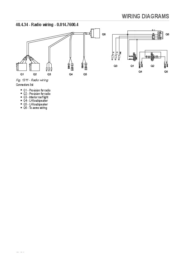
40.4.34 – Radio wiring – 0.014.7600.4
40.4.35 – Positions of radio-loudspeaker wiring connectors
Deutz-Fahr Agrokid 210, Agrokid 220, Agrokid 230 Repair Service Manual