Complete service repair manual for Hyster G019 (H300HD, H330HD, H360HD, H360HD-12EC & H13.00XM, H14.00XM, H16.00XM-6, H10.00XM-12EC, H12.00XM-12EC Europe), with all the shop information to maintain, diagnose, repair, and rebuild like professional mechanics.
Hyster G019 (H300HD, H330HD, H360HD, H360HD-12EC & H13.00XM, H14.00XM, H16.00XM-6, H10.00XM-12EC, H12.00XM-12EC Europe) workshop service & repair manual includes:
* Numbered table of contents easy to use so that you can find the information you need fast.
* Detailed sub-steps expand on repair procedure information
* Numbered instructions guide you through every repair procedure step by step.
* Troubleshooting and electrical service procedures are combined with detailed wiring diagrams for ease of use.
* Notes, cautions and warnings throughout each chapter pinpoint critical information.
* Bold figure number help you quickly match illustrations with instructions.
* Detailed illustrations, drawings and photos guide you through every procedure.
* Enlarged inset helps you identify and examine parts in detail.
Hyster G019 (H300HD, H330HD, H360HD, H360HD-12EC & H13.00XM, H14.00XM, H16.00XM-6, H10.00XM-12EC, H12.00XM-12EC Europe) Service Manual.pdf
Total Pages: 2,021 pages
File Format: PDF
Language: English
G019 (H13.00XM, H14.00XM, H16.00XM-6, H10.00XM-12EC, H12.00XM-12EC Europe)….2
1494140-1600SRM0936-(03-2007)-UK-EN….3
toc….3
Steering System….3
Safety Precautions Maintenance and Repair….4
General….7
Description….7
Steering Wheel and Column Assembly….9
General….9
Steering Wheel and Horn….9
Remove….9
Install….9
Steering Control Unit Repair….11
General….11
Description….11
Operation….11
Remove….12
Disassemble….12
Clean….15
Assemble and Install….15
Steering System Air Removal….21
Steering Relief Pressure Check….22
Troubleshooting….22
1494141-1800SRM0937-(03-2007)-UK-EN….27
toc….27
Dry Brake System….27
Safety Precautions Maintenance and Repair….28
General….31
Description….31
Operation….32
Service Brakes….32
Parking Brake….34
Air Tank Repair….35
Relief Valve….35
Drain Valve….35
Brake Pedal Valve Repair….36
Remove….36
Disassemble, Inspect, and Assemble….36
Install….36
Air Chambers Repair….37
Remove….37
Disassemble….37
Inspect….38
Assemble….39
Install….39
Actuator Arms Repair….39
Remove….39
Inspect….40
Install….40
Brake Assemblies Repair….41
Brake Shoe, Remove….41
Camshaft, Remove….43
Clean….43
Inspect….44
Camshaft, Install….44
Brake Shoe, Install….45
Air Dryer….46
Description….46
Cartridge….46
Remove….46
Install….46
Filter….46
Remove….46
Install….46
Quick-Release Valve….48
Governor Check and Adjustment for Air Compressor….48
Brake Shoes Adjustment….49
Specifications….50
Troubleshooting….50
Service Brakes….50
Service Brakes, Park Function ….53
tables….27
Table 1. Air Chambers Operation….34
1494142-1900SRM0938-(03-2007)-UK-EN….57
toc….57
Hydraulic System….57
Safety Precautions Maintenance and Repair….58
General….61
Description and Operation….61
Hydraulic Tank….61
Hydraulic Pump….62
Steering Priority Flow Valve….62
Pilot Valve….63
Main Control Valve….65
Unloader Valve….66
Hydraulic Operation….67
Checks and Adjustments….70
Quick Disconnect Fittings….70
Steering Priority Flow Valve….70
Steering Relief Pressure….70
Modulator Valve….71
Pilot Valve and Pressure Reducing Valve….71
Accumulator….72
Filter….72
Main Control Valve….72
Relief Pressure Check….72
Check Valves….73
Unloader Valve….73
Hydraulic Pump Repair….74
Remove….74
Disassemble….74
Clean and Inspect….74
Assemble….75
Install….76
Pilot Accumulator Replacement ….76
Remove….76
Install….76
Pilot Valve Repair….77
Remove….77
Disassemble….78
Clean and Inspect….78
Assemble….78
Install….78
Control Levers and Joystick Repair….79
Remove….79
Install….79
Calibration and Diagnostics….80
General….80
Description….80
Lever and Joystick Calibration….80
Flow Adjustment….80
Dead Band Value Setting….81
Lowering Delay….82
PWM and I/O Module Readouts….82
Function Disable….83
General Startup….83
Minimum system requirements….83
Install the Hydraulic Controls Program….83
DelayTimeFile (Reset)….83
Select the Processor Speed….84
Hydraulic Controls Program….84
Calibration….86
Joystick/Lever Calibration….86
Levers….86
Joystick….86
Valve Flow Adjustment….87
Diagnostics….87
Calibration System Shutdown….87
LED Diagnostics….88
Electrical Connections….91
Specifications….95
tables….57
Table 1. Main Control Valve Port Settings….63
Table 2. Processor Speed Settings….83
Table 3. PWM Board LED Error Codes….88
Table 4. Altering PT FLT I/O Board LED's (Old Logic)….89
Table 5. Altering PT FLT I/O Board LED's (New Logic)….89
Table 6. Fixed PT Logic I/O Boards LED's….90
Table 7. ECH….90
Table 8. PWM Driver Module….91
Table 9. Input/Output Module 1….92
Table 10. Input/Output Module 2….93
Table 11. Altering PT FLT….94
Table 12. Fixed PT FLT….94
Table 13. ECH….95
1494953-1400SRM0944-(03-2007)-UK-EN….99
toc….99
Planetary Drive Axle….99
Safety Precautions Maintenance and Repair….100
General….103
Description….103
Operation….105
Identification….105
Removal….106
Disassembly….106
Planetary Spider and Gearing Assembly H8.00-12.00XM (H170-280HD)….106
Planetary Spider and Gearing Assembly H13.00-14.00XM (H300-330HD….108
Wheel End….110
Spindle and Piston Housing….111
Cleaning….112
Clean Ground or Polished Parts….112
Clean Parts With Rough Finish….112
Clean Axle Assemblies….112
Drying Cleaned Parts….112
Corrosion Prevention….112
Parts Inspection….113
Tapered Roller Bearings….113
Bevel Pinion and Ring Gear Sets….114
Main Differential Assembly….114
Axle Shafts….114
Yoke….114
Brakes….114
Repair or Replace Parts….114
Repair Welding….114
Apply Silicone Gasket Material….115
Assembly….115
Spindle and Piston Housing to Axle Housing….115
Wet Disc Brakes….116
Adjust Wheel Bearing Preload….117
Planetary Spider and Gearing Assembly H8.00-12.00XM (H170-280HD)….118
Planetary Spider and Gearing Assembly H13.00-14.00XM (H300-330HD….119
Planetary Spider Assembly….119
Installation….120
Fill Wet Disc Brakes With Hydraulic Fluid….120
Torque Specifications….121
Lubrication Specification….122
1494955-2000SRM0943-(03-2007)-UK-EN….125
toc….125
Main Control Valve….125
Safety Precautions Maintenance and Repair….126
General….129
Description….129
Operation….132
Lift Section….132
Tilt/Auxiliary Section….132
Relief Valves….132
Unloader Valve….132
Main Control Valve Repair….135
Remove….135
Disassemble….135
Auxiliary Side….135
Lift Side….135
Clean and Inspect….138
Assemble….138
Auxiliary Side….138
Lift Side….138
Install….138
Pressure Relief Valve Check and Adjustment….139
Check and Adjust….139
Replace….139
Specifications….140
Troubleshooting….140
1498445-1400SRM0945-(03-2007)-UK-EN….145
toc….145
Planetary Drive Axle….145
Safety Precautions Maintenance and Repair….146
General….149
Description….149
Operation….151
Identification….151
Removal….152
Disassembly….152
Brake Drum….152
Planetary Spider and Gearing Assembly H8.00-12.00XM (H170-280HD)….153
Dry Brakes….155
Planetary Spider and Gearing Assembly H13.00-14.00XM (H300-330HD….155
Spindle and Brake Spider….157
Cleaning….158
Ground or Polished Parts….158
Parts With Rough Finish….158
Axle Assemblies….158
Drying Cleaned Parts….158
Corrosion Prevention….158
Parts Inspection….159
Tapered Roller Bearings….159
Bevel Pinion and Ring Gear Sets….160
Main Differential Assembly….160
Axle Shafts….160
Yoke….160
Brakes….160
Repair or Replace Parts….160
Repair Welding….160
Apply Silicone Gasket Material….161
Assembly….161
Spindle, Brake Spider, and Brake….161
Wheel End….162
Adjust Wheel Bearing Preload….163
Planetary Spider and Gearing Assembly H8.00-12.00XM (H170-280HD)….164
Planetary Spider and Gearing Assembly H13.00-14.00XM (H300-330HD….165
Planetary Spider Assembly….165
Installation….166
Torque Specifications….167
Lubrication Specification….168
1498450-1800SRM0951-(03-2007)-UK-EN….171
toc….171
Wet Brake System….171
Safety Precautions Maintenance and Repair….172
General….175
Description and Operation….175
Service Brakes….175
Parking Brake….175
Oil Cooler Circuit….175
Pressure Switch Replacement….179
Accumulators Replacement….179
Brake Treadle Valve Repair….179
Remove and Disassemble….179
Clean and Inspect….180
Assemble and Install….180
Parking Brake Valve Repair….180
Remove….180
Clean and Inspect….180
Repair….180
Install….180
Parking Brake Caliper Repair….181
Remove….181
Disassemble….183
Inspect….183
Install….183
Adjust….183
Brake Pad Repair….184
Inspect….184
Remove….184
Install….184
Seals Repair….184
Remove….184
Install….185
Service Brake Repair….185
Remove and Disassemble….185
Drain Lubricating Oil….185
Drain Coolant Oil….192
Disconnect Brake Lines….192
Wheel End With Outer Bearing on Ring Gear Hub Journal H13.00-14….192
Wheel End With Outer Bearing on Spindle Journal H8.00-12.00XM (H….193
Brake Disc Housing Assembly Wheel End….194
Brake Piston Housing….195
Brake Piston Housing and Wheel Spindle….196
Inspect….196
Clean….198
Assemble….199
Wheel Spindle….199
Brake Piston Housing….199
Piston Assembly….201
Brake Disc Housing….201
Duo-Cone Face Seal Into Brake Disc Housing and Into Hub….203
Check for Correct Installation of Duo-Cone Seal….204
Wheel Hub to Brake Disc Housing….205
Adjust….206
Fill Brake System With Coolant Oil….206
System Air Removal….207
Adjust Brake With New Disc Pack….207
Coolant Change Intervals….208
Coolant Draining and Filling….208
Specifications….210
Minimum Brake Disc Thickness….213
Hydraulic Fluid for Brake Actuation….213
Brake Coolant Specifications….213
Coolant Change Intervals….213
Hydraulic Fluid Specifications….213
Troubleshooting….213
Brake Does Not Apply….213
Brake Does Not Release….214
Brake Performance….214
Brake Leaks Actuation Fluid….215
Brake Cooling Fluid Leakage….216
Brake Noise and Vibration….216
Brake Overheats….216
tables….171
Table 1. Brake Pad Adjustment….183
Table 2. Minimum Brake Disc Thickness….197
Table 3. Formed Seal Wear Chart….197
1503241-5000SRM0969-(03-2007)-UK-EN….221
toc….221
Empty Container Handling Attachment….221
Safety Precautions Maintenance and Repair….222
General….225
Description….225
Operation….230
General….230
Selector Valves….230
Sideshift Circuit….230
Extend and Retract Circuit….230
Twist Lock Circuit and Control….231
Model 553 – Horizontally Mounted….231
Model 558 – Vertically Mounted….231
Lifting Hooks….231
Model 555….231
Indicator Lights and LEDs….231
Lift Interrupt and Override….232
Overlowering Interrupt and Override….232
Carriage and Attachment Repair….232
Remove….232
Attachment Without Carriage Repair….233
Remove….233
Sideshift Cylinders Repair….234
Remove….234
Disassemble….234
Assemble….234
Extension Cylinders Repair….235
Remove….235
Disassemble….235
Clean and Inspect….235
Assemble….235
Install….235
Vertical End Beams Repair….237
Remove….237
Install….237
Hose Replacement in End Beams….237
Twist Locks Repair for Model 553….238
Remove….238
Disassemble….238
Clean and Inspect….238
Assemble….238
Hooks Replacement for Model 555….239
Inspect….239
Remove….239
Install….239
Twist Locks Repair for Model 558….240
Disassemble….240
Clean and Inspect….240
Assemble….240
Bleed the System….241
Valve Assembly….241
Slide Pad Replacement….242
Adjustments….242
Twist Lock Angle Adjustment….242
Model 558 Only….242
LOCKED/NOT LOCKED Sensors Adjustment….243
Model 553….243
Model 558….243
Seated Sensor Adjustment….243
Model 553….243
Model 558….243
Overlowering Protection Sensor Adjustment (Models 553 and 558)….243
Torque Chart….244
Maintenance….244
Additional Attachment Maintenance….246
Interface Boxes….247
Model 555….247
Models 553 and 558….247
Troubleshooting….249
tables….221
Table 1. Torque Chart….244
Table 2. Inspect and Adjust (See Figure 14 )….245
Table 3. Lubricate (See Figure 14 )….246
Table 4. Replace (See Figure 14 )….246
1553599-4000SRM1062-(03-2007)-UK-EN….267
toc….267
Masts and Carriages….267
Safety Precautions Maintenance and Repair….268
General….271
Description….271
Operation….272
Two-Stage Mast….272
Three-Stage Mast….273
Safety Procedures When Working Near Mast….274
Forks Repair….277
Remove….277
Inspect and Adjust….277
Install….277
Carriage Repair….278
Description….278
Three Function….278
Four to Six Function….278
Remove….278
Disassemble….279
Clean and Inspect….281
Assemble….281
Install….281
Sideshift Cylinder Repair….282
Remove….282
Disassemble….282
Clean and Inspect….282
Assemble….282
Install….282
Fork Positioner Cylinders Repair….286
Remove….286
Disassemble….286
Clean and Inspect….286
Assemble….286
Install….286
Directional Control Valve Repair….293
Remove….293
Disassemble….293
Clean and Inspect….293
Assemble….294
Install….294
Mast Repair….294
Two- and Three-Stage Mast….294
Remove….294
Disassemble….299
Clean and Inspect….301
Assemble….302
Install….303
Three-Stage Mast (Four Cylinders)….303
Remove….303
Disassemble….305
Clean and Inspect….307
Assemble….307
Install….307
Fork Carriage Chains….309
Adjust….309
Bearing Rollers….311
Description….311
Lubrication….311
Clearance….311
Remove and Disassemble….311
Assemble….312
Mast Profile….312
Lift Cylinders Description….312
Piston-Type Cylinders….312
Displacement-Type Cylinders….312
Lift Cylinders Repair….313
Remove….313
Disassemble….315
Clean and Inspect….315
Assemble….315
Install….316
Mast Operation Check….316
Lift and Tilt System Leak Checks….317
Lift System….317
Tilt System….317
Tilt Cylinder Stroke and Backward Tilt Angle Adjustment….318
Lift Chain Adjustments….318
Mast Adjustments….319
Bearing Blocks, Two-Stage Masts….319
Wear Plates….319
Carriage Adjustment….319
Troubleshooting….321
tables….267
Table 1. Allowable Mast Movement from Internal Leakage….317
1556871-2200SRM1105-(03-2007)-UK-EN….325
toc….325
Instrument Panel Indicators and Senders….325
Safety Precautions Maintenance and Repair….326
General….329
Description….329
General….329
Instrument Panel Meters, Indicators, and LCD Display….329
Connector….335
Seat Switch Logic….336
Central Warning Light Output….336
Buzzer Output….336
Instrument Panel….338
Remove….338
Sender Replacement….339
Fuel Level Sender (Diesel Engine Only)….339
Engine Oil Pressure Sender….340
Brake Pressure Sender….340
Low Coolant Sender….340
Vacuum Switch….340
Specifications….341
Troubleshooting….342
tables….325
Table 1. Instrument Panel and Indicators….330
Table 2. Pin Description….335
Table 3. Sender Description….336
1564053-0600SRM1101-(11-2007)-UK-EN….347
toc….347
Cummins Diesel/LPG Engine Fault Code Guide….347
Safety Precautions Maintenance and Repair….348
General….351
Fault Codes….351
Normal Mode….351
Fault Log Mode….351
Access….351
Exit….352
Clear….352
Electronic Throttle Calibration….352
Electronic Throttle Calibration Procedure….352
tables….347
Table 1. Error Code Descriptions….353
1586990-8000SRM1181-(03-2007)-UK-EN….369
toc….369
Assembly Guide….369
Safety Precautions Maintenance and Repair….370
List of All Special Tools and Equipment Needed for the Assembly….373
General Considerations Before Starting the Job….373
Preparation of the Components Before Assembly….374
Liquefied Petroleum Gas (LPG Engines Only)….374
Remove….374
Install….375
Checking of the Wheels….375
Air Pressure….375
Drive Wheels….376
Steer Wheels….380
Wheel Nut Torque….383
Mast Label Placement….384
Safety Procedures When Working Near Mast….385
Mast Installation….387
Mast….387
Tilt Cylinder Pin Installation….390
Lift Cylinder Hose Connection….391
Truck Header Hoses and Electrical Cable Connections….392
Mast Light Connection….394
Carriage Installation….395
Carriage Header Hoses and Electrical Cable Connection….396
Fork Installation….399
Exhaust Extension Tube Installation….400
Lights Installation – Operator Compartment….402
Hydraulic Oil Check….403
Lubrication Points….404
Check Points….405
Checkpoint 1….405
Checkpoint 2….405
Checkpoint 3….405
Checkpoint 4….405
Checkpoint 5….405
General Truck Install Procedures….405
tables….369
Table 1. Mast Hanger Pins Capscrew Torques….390
1663926-8000SRM1346-(05-2007)-UK-EN….409
toc….409
Diagrams….409
Safety Precautions Maintenance and Repair….410
1663927-8000SRM1347-(12-2007)-UK-EN….463
toc….463
Periodic Maintenance….463
Safety Precautions Maintenance and Repair….464
General….469
Serial Number Data….469
How to Move a Disabled Lift Truck….470
How to Tow the Lift Truck….470
How to Put a Lift Truck on Blocks….470
How to Raise the Drive Tires….471
How to Raise the Steer Tires….471
Maintenance Schedule….472
Empty Container Attachment Maintenance….479
Maintenance Procedures Every 8 Hours or Daily….481
How to Make Checks With the Engine Stopped….481
Safety Labels….481
Tires and Wheels….481
Inspection of Forks, Mast, and Lift Chains….482
Header Hose Assembly….483
Forks, Adjust….483
Forks, Remove….483
Forks, Install….483
Precleaner for Air Filter….484
Check for Fuel, Oil, or Coolant Leaks….484
Coolant Hoses….484
Engine Air Intake Piping….484
Drive Belts….484
Radiator Sections for Engine Coolant, Charge Air Cooler, and Hyd….485
Engine Compartment….485
Operator Restraint System (Seat Belt and Seat Rails)….485
Steering Column Latch….485
Hydraulic System Oil….485
Windshield Washer Fluid….486
Engine Oil….486
How to Add Fuel to the Lift Truck….488
Diesel Fuel….488
Liquefied Petroleum Gas (LPG)….489
Remove….489
Fill….489
Install….490
How to Make Checks With the Engine Running….490
Gauges, Lights, Horn, Fuses, and Relays….490
Engine and Transmission Fault Codes….493
Cooling System….493
Diesel Fuel Filter/Water Separator….494
Electrical System….494
Engine Oil Pressure….494
Fuel System….494
Engine Air Filter….494
Control Levers and Pedals….494
Steering System….494
Parking Brake….494
Service Brakes….495
Lift System Operation….495
Transmission….495
Transmission Oil….495
First Inspection After First 100 Hours of Operation….496
Lift Chains….496
Hydraulic System Oil Filter….496
Engine Oil Filter….496
Transmission Oil Filter….497
Hydraulic Pilot Valve Oil Screen….497
Wet Brake System Filter….497
First Inspection After First 500 Hours of Operation….497
Cab Mounting Bolts….497
Maintenance Procedures Every 250 Hours or Monthly….498
Twist Locks….498
Lifting Hooks (Model 555)….498
Empty Container Attachment….498
Maintenance Procedures Every 250 Hours or 3 Months….498
Lift Chains….498
Wheel Nuts….499
Forks….499
LPG Crankcase Breather….499
Mast Bearing Block Surfaces and Strip Bearings….499
Sideshift Carriage Sliding Surfaces….500
Fork Pins and Guides….500
Maintenance Procedures Every 500 Hours or 3 Months….500
Rod Ends at Sideshift Cylinder….500
Mast Pivot Pins….500
Tilt Cylinder Pivot Pins….500
Steering Axle Tie Rod Pins….500
King Pins….500
Shafts for Air Brake Actuator Arms….500
Drive Shaft….500
Maintenance Procedures Every 500 Hours or 6 Months….501
Cab Air Filter….501
Planetary Drive Axle and Differential….501
Header Hose Assembly….501
Hydraulic Tank Breather….501
Air Compressor (Air Brakes Only)….501
Spark Plug Wire (LPG Engine Only)….501
Cooling Fan….501
Drive Belts….501
Coolant….501
Fuel Pump….501
Engine Oil….502
Engine Oil Filter….502
Diesel Fuel Filter….502
Maintenance Procedures Every 1000 Hours or 6 Months….502
Extension Cylinder Support Wear Pads (ECH Only)….502
Brake Accumulator (Wet Brake Only)….502
Coolant Fan Belt Tensioner….502
Fan Hub….504
Pilot Valve Accumulator….504
LPG Tank Hinges….505
Cab Door Hinges….505
LPG Vapor Fuel Filter….505
Wet Brake System Filter….505
Maintenance Procedures Every 1000 Hours or 1 Year….506
Engine Valve Adjustment….506
Diesel Fuel Filter/Water Separator….506
Transmission Oil….506
Transmission Oil Filter….506
Transmission Breather….506
Maintenance Procedures Every 1500 Hours or 6 Months….506
Drive Axle and Differential….506
Maintenance Procedures Every 2000 Hours or 1 Year….506
Transmission Calibration….506
Inching Pedal Sensor Calibration….506
Parking and Service Brakes….506
Vibration Damper….507
Engine and Transmission Isolators….507
Engine Air Intake Piping….507
Brake Air Pressure Lines….507
Spark Plug (LPG Engines Only)….508
LPG Liquid Fuel Filter….508
Maintenance Procedures Every 3000 Hours or 1 Year….509
Pedals, Levers, Seat Rails, and Hinges….509
Air Dryer Cartridge….509
Hydraulic System Oil and Filter….509
Maintenance Procedures Every 3000 Hours or 2 Years….510
Hydraulic Pilot Valve Oil Screen….510
Maintenance Procedures Every 4000 Hours or 2 Years….510
Spark Plug Wire (LPG Engines Only)….510
Steer Wheels Hub Bearings….510
Maintenance Procedures Every 5000 Hours….511
Twist Locks or Hooks….511
Maintenance Procedures Every 5000 Hours or 3 Years….511
Air Conditioning….511
Maintenance Procedures Every 6000 Hours or 2 Years….511
Turbocharger….511
Maintenance Procedures Every 12,000 Hours or 5 Years….512
Cooling System….512
Safety Procedures When Working Near Mast….513
Lift and Tilt System Leak Check….514
Lift System….514
Tilt System….514
Wheel and Tire Replacement….515
Remove Wheels From Lift Truck….515
Pneumatic Tires….516
Remove Tire From Wheel….516
Remove Tire From Two- and Four-Piece Wheel….516
Install Tire on Wheel….517
Install Tire on Two- and Four-Piece Wheel….518
Add Air to Tires….519
Solid Rubber Tires….519
Remove Tire From Wheel….519
Install Tire on Wheel….521
Wheels, Install….522
tables….463
Table 1. Daily Inspections − Condition Check….473
Table 2. Daily Inspections − Fluid Level Check….474
Table 3. Daily Inspections − Checks With the Engine Running….474
Table 4. Initial 100-Hour Check or Change….475
Table 5. Initial 500-Hour Check or Change….475
Table 6. Periodic Maintenance Schedule − Inspect and Adjust….476
Table 7. Periodic Maintenance Schedule − Lubricate….477
Table 8. Periodic Maintenance Schedule − Change….478
Table 9. Empty Container Attachment Maintenance − Inspect and ….480
Table 10. Empty Container Attachment Maintenance − Lubricate….480
Table 11. Empty Container Attachment Maintenance − Replace….480
Table 12. Approved LPG Engine Oil Types….488
Table 13. Valve Adjustment Specifications….506
Table 14. Allowable Mast Movement from Internal Leakage….515
1663928-8000SRM1348-(03-2008)-UK-EN….525
toc….525
Capacities and Specifications….525
Safety Precautions Maintenance and Repair….526
Counterweight Weights….529
Lift Truck Weights….529
Capacities….530
Engine Specifications….531
Hydraulic System….532
Electrical System….532
Tire Sizes….532
Mast Speeds….533
Torque Specifications, Cummins Diesel….533
Lubrication System….533
Torque Specifications, General….534
Transmission….534
Driveline and Axle….534
Counterweight….534
Differential….534
Brakes – Wet….534
Brakes – Dry….534
Steering….534
Wheel Nuts….534
Hydraulic System….535
Mast….535
Carriage….535
Tilt Cylinders….535
Wiper Arms, Front….535
1665777-0100SRM1349-(01-2008)-UK-EN….539
toc….539
Frame….539
Safety Precautions Maintenance and Repair….540
General….543
Description….543
Air Cleaner….544
Remove….544
Install….544
Exhaust System….545
Remove….545
Install….545
Hood Assembly….546
Remove….546
Install….547
Hydraulic Tank….547
Remove….547
Inspect….549
Clean….549
Additional Preparations for Repair….550
Repair….550
Small Leaks….550
Large Leaks….550
Preparations for use After Repair….550
Install….551
Fuel Tank….552
Remove….552
Repair….556
Install….556
Engine….557
Remove….557
Install….562
Counterweight….563
General….563
Remove….564
Install….565
Label Replacement….565
tables….539
Table 1. Counterweight Weights….563
1665778-0700SRM1350-(03-2007)-UK-EN….569
toc….569
Multiple Aligned Cooling System….569
Safety Precautions Maintenance and Repair….570
General….573
Description….574
Radiator….574
Radiator Cap….574
Thermostat….574
Water Pump….575
Fan and Fan Shroud….575
Cooling System Checks….575
Radiator….575
Thermostat….575
Water Pump….576
Exhaust Leaks….576
Fan and Fan Shroud….576
Cooling System Repair….577
Remove….577
Install….578
Core Repair….579
Remove….579
Install….579
Radiator Cleaning….579
Drain….579
Clean….579
Fill….580
Troubleshooting….580
1665779-2200SRM1351-(04-2007)-UK-EN….585
toc….585
Electrical System….585
Safety Precautions Maintenance and Repair….586
Description….589
Warning Devices….594
General….594
Description….595
Operator-Controlled Horn….595
Reverse Warning Horns/Lights….595
Warning Lights….595
Strobe Light….595
Brake Lights….597
Hazard Lights….597
Replace….597
General….597
Horns….597
Horn Relay….597
Light Assemblies….597
Flashing Unit….598
Meters, Senders, and Switches….598
General….598
1670739-1300SRM1356-(07-2008)-UK-EN….611
toc….611
Transmission….611
Safety Precautions Maintenance and Repair….612
General….615
Transmission Repair….615
Remove….615
Disassemble….619
Transmission Case, Disassemble….620
Torque Converter Housing, Disassemble….637
Forward Clutch, Disassemble….642
First-Speed Clutch, Disassemble….644
Reverse and Second-Speed Clutch….649
Reverse Clutch, Disassemble….649
Second-Speed Clutch, Disassemble….654
Third-Speed Clutch, Disassemble….656
Third Clutch Shaft, Disassemble….658
Turbine Shaft, Disassemble….659
Output Shaft, Disassemble….660
Impeller, Disassemble….661
Turbine, Disassemble….663
Clean and Inspect….665
Housings….665
Oil Seals and Gaskets….665
Bearings….666
Gears and Shafts….666
Assemble….666
Turbine, Assemble….666
Impeller, Assemble….668
Output Shaft, Assemble….670
Turbine Shaft, Assemble….672
Third Clutch Shaft, Assemble….673
Third-Speed Clutch, Assemble….674
Reverse and Second-Speed Clutch….677
Second-Speed Clutch, Assemble….677
Reverse Clutch, Assemble….680
First-Speed Clutch, Assemble….684
Forward Clutch, Assemble….689
Torque Converter Housing, Assemble….692
Transmission Case, Assemble….697
Install….718
Control Valve Removal and Installation….720
Remove….720
Install….720
Control Valve Disassemble and Assemble….722
Remove….722
Transmission Frame Bracket….722
Control Valve Cover….722
Control Valve Components….722
Install….724
Control Valve Components….724
Control Valve Cover….724
Transmission Frame Bracket….724
Torque Specifications….725
Torque Specifications for Lubricated or Plated Screw Threads….725
Troubleshooting….727
tables….611
Table 1. Grade 5….725
Table 2. Grade 8….725
Table 3. Grades 8.8, 10.9, and 12.9….726
Table 4. O-ring Port Plug Torque Chart….727
Table 5. Pipe Plug Torque Chart….727
1671895-1300SRM1358-(07-2008)-UK-EN….731
toc….731
Transmission….731
Safety Precautions Maintenance and Repair….732
General….737
Description….737
General….737
Operation….740
Hydraulic Operation….740
1st/3rd Selector Valve….742
Cooling and Lubrication….742
Control System….744
General….744
APC200 Controller….744
Self Test….744
Protection Modes….744
Limp Home Mode….744
Shut Down Mode….744
Transmission Exceed Codes….744
Fault Codes….745
Description….745
Fault Log Mode….745
Access….745
Exit….745
Clear….746
Fault Rectification….746
Hydraulic Control Valve….747
Hydraulic Control Valve Repair….748
Solenoid Replacement….748
Pressure Check….749
Pressure Specifications….749
Pressure, Speed, and Temperature Sensors….750
Pressure Switch….754
Test….754
Speed Sensor….754
Test….755
Temperature Sensors….756
Test….756
Transmission Test and Calibration….756
Precautions….756
Stall Test….756
Description….756
Stall Test Procedure….756
Clutch Calibration….757
Description….757
Procedure….758
Inching Calibration….758
Description….758
Brake and Inching Pedal Adjustment….759
Inching Sensor Adjustment….759
Inching Sensor Calibration….760
Electrical Specifications….760
APC200 Operation….761
General….761
General Information Group….761
Fault Codes….762
Indication of Protection Modes….762
Test Function Group….763
Digital Input Test….764
Analog Input Test….765
Speed Sensor Test….765
Output Test….766
Voltage Test….767
Calibration Group….767
Calibration Mode….767
Clutch Filling Calibration….768
Heat Up Mode….768
Inching Sensor Calibration….769
Inching Pedal Sensor Adjustment….769
Inching Sensor Calibration….769
TE-Userlink….770
Description….770
Connection….770
Table 12. Transmission Exceed Codes….803
Table 13. APC200 Fault Codes….803
Table 14. Common Calibration Condition Messages….814
Table 15. Fault Codes During Clutch Calibration….815
tables….731
Table 1. Activated Solenoids and Gear Selection….742
Table 2. Control Valve Pressure Check Ports….747
Table 3. Transmission Housing Check Ports….753
Table 4. Sensors and Switches….754
Table 5. Speed Sensor Check Values….755
Table 6. Temperature Sensor (In Speed Sensor) Resistance Versus ….760
Table 7. General Information Group….762
Table 8. Digital Input Test….764
Table 9. Analog Input Test….765
Table 10. Speed Sensor Test….766
Table 11. Output Test….766
1689543-0100SRM1383-(09-2008)-UK-EN….819
toc….819
Operator's Cab….819
Safety Precautions Maintenance and Repair….820
General….827
Description of Operation….828
Cab Structure….828
Cab Supporting Frame….828
Cab Tilt Cylinder….830
Extending the Cab Tilt Cylinder….830
Retracting the Cab Tilt Cylinder….831
Heater System….831
Air Conditioning….833
General….833
Dryer….834
Control Systems, Sensors, and Switches….834
Oil Filling for Cab Tilt System….835
Raising and Lowering Cab….836
Raise Cab….836
Lower Cab….837
Cab….837
Remove….837
Install….839
Cab Door Assembly….840
Cab Door….840
Remove….840
Install….840
Door Hinge….840
Remove….840
Install….840
Door Latch….840
Remove….840
Install….841
Door Handle….842
Remove….842
Install….842
Door Release….842
Remove….842
Install….842
Door Pushbutton….842
Remove….842
Install….842
Cab Tilt System….842
Electric Tilt Pump….842
Remove….842
Install….843
Hand Pump….843
Remove….843
Install….843
Cab Tilt Cylinder….843
Remove….843
Disassemble….843
Clean….845
Inspect….845
Assemble….845
Install….846
Latch….846
Remove….846
Install….846
Brake and Inching Pedals….847
Brake and Inching Pedals….847
Remove….847
Install….847
Brake Pedal Adjustment….847
Dry Brake….847
Wet Brake….847
Inching Pedal Adjustment….848
Dry Brake….848
Wet Brake….848
Inching Pedal Sensor Adjustment Using Userlink® Program….848
Inching Pedal Sensor Calibration Procedure Using Userlink® Progr….849
Inching Pedal Sensor Adjustment Using the APC200….849
Inching Pedal Sensor Calibration Procedure Using the APC200….850
Accelerator Pedal Sensor….851
Check….851
Adjust….851
Seat Assembly….852
Seat….852
Remove….852
Install….852
Seat Cushion….852
Remove….852
Install….852
Back Cushion….853
Remove….853
Install….853
Seat Suspension….853
Remove….853
Install….853
Boot….853
Remove….853
Install….853
Shock Absorber….853
Remove….853
Install….853
Compressor….854
Remove….854
Install….858
Power Assist Armrest….864
Release Cable….864
Remove….864
Install….864
Gas Spring….864
Remove….864
Install….864
Armrest Assembly….865
Adjust….865
Joystick….865
Remove….865
Install….865
Levers….866
Remove….866
Install….866
Rocker Switches….866
Remove….866
Install….866
Cover….866
Remove….866
Install….866
Instrument Panel….867
Key Switch….867
Remove….867
Install….867
12V Power Socket….867
Remove….867
Install….867
Electric-Operated Heater Control and Fan Control….868
Remove….868
Install….868
Cable-Operated Heater Control and Air Control….869
Remove….869
Install….869
Air Conditioning Switch….869
Remove….869
Install….869
Rocker Switches….869
Remove….869
Install….869
Parking Brake Switch….870
Remove….870
Install….870
Indicator Display….870
Remove….870
Install….870
Instrument Panel Top Console….871
Remove….871
Install….871
Steering Wheel and Column Assembly….871
Steering Wheel and Horn….871
Remove….871
Install….871
Steering Column Assembly….873
Remove….873
Install….874
Adjustment Mechanism….874
Remove….874
Install….874
Main Warning Lights….874
Remove….874
Install….874
Shift Lever….875
Remove….875
Install….875
Turn Signal Lever….875
Remove….875
Install….875
Window Wipers Replacement….876
Window Wiper Assembly, Replace….876
Remove….876
Install….876
Window Wiper Motor Replacement….877
Front Window Wiper Motor Assembly….877
Remove….877
Install….877
Rear Window Wiper Motor Assembly….877
Remove….877
Install….877
Top Window Wiper Motor Assembly….878
Remove….878
Install….878
Window Washer System….878
Window Washer Reservoir….878
Remove….878
Install….878
Window Washer Motors and Pumps….878
Remove….878
Install….879
Window Washer Hoses….879
Top/Rear….879
Remove….879
Install….880
Front….880
Remove….880
Install….881
Window Washer Nozzles….881
Front….881
Remove….881
Install….881
Rear….881
Remove….881
Install….882
Top….882
Remove….882
Install….882
Window Replacement….882
Front Window….884
Remove….884
Install….884
Rear Window….884
Remove….884
Install….884
Top Window….885
Remove….885
Install….885
Door Window….885
Upper/Lower Window….885
Remove….885
Install….885
Sliding Window….885
Front Sliding Window….885
Remove….885
Install….887
Rear Sliding Window….887
Remove….887
Install….887
Weather Strip, Replace….888
Window Stopper, Replace….888
Sliding Tracks, Replace….888
Window Seals, Replace….888
Sliding Window Frame….888
Remove….888
Install….888
Heater System Repair….889
Heater Assembly….889
Access….889
Remove….889
Install….890
Heater Assembly Parts, Replace….890
Heater Core….890
Remove….890
Install….891
Evaporator Core….891
Remove….891
Install….891
Blower….892
Remove….892
Install….892
Water Valve….892
Remove….892
Install….893
Vent Door….893
Remove….893
Install….893
Push/Pull Cable, Replace….894
Water Valve Cable….894
Remove….894
Install….894
Vent Door Cable….895
Remove….895
Install….895
Floor Mat….896
Front….896
Remove….896
Install….897
Rear….897
Remove….897
Install….897
Radio Console….898
Remove….898
Install….898
Air Duct….898
Front….898
Remove….898
Install….898
Rear….899
Remove….899
Install….899
Accessories….900
Mirror….900
Remove….900
Install….900
Sunshade….900
Top….900
Remove….900
Install….900
Rear….900
Remove….900
Install….901
Map Light….901
Remove….901
Install….901
Interior Fan….901
Remove….901
Install….901
Training Seat….901
Install….901
Remove….901
Air Conditioning Technical Detail….902
Technical Detail….902
Label Replacement….903
tables….819
Table 1. Air Conditioning Specifications….902
897108-1600SRM0326-(03-2007)-UK-EN….907
toc….907
Steering Axle….907
Safety Precautions Maintenance and Repair….908
General….911
Description….911
Steering Axle Assembly Repair….916
Steering Axle H3.50-5.00XL (H70-110XL) (G005), S3.50-5.50XL (S70….916
Remove….916
Install….916
Steering Axle H6.00-7.00XL (H135-155XL, H135-155XL 2 ) (F006, G0….917
Remove….917
Install….917
Wheels and Hubs Repair (All Units)….918
Remove and Disassemble….918
Clean….918
Inspect….918
Assemble and Install….918
Spindles and Bearings Repair (All Units)….920
Remove….920
Clean….920
Assemble and Install….921
Tie Rods Repair (All Units)….922
Remove….922
Clean….922
Install….922
Steering Cylinder Repair….925
Remove and Disassemble….925
Clean and Inspect….925
Assemble and Install….925
Troubleshooting….926
910072-1400SRM0046-(07-2007)-UK-EN….931
toc….931
Differential….931
Safety Precautions Maintenance and Repair….932
General….935
Description….935
Differential Repair….936
Remove….936
Differential Carrier From Axle Housing, Remove….936
Differential and Ring Gear From Differential Carrier, Remove….938
Drive Pinion and Pinion Carrier From Differential Carrier, Remov….940
Disassemble….941
Differential and Ring Gear Assembly, Disassemble….941
Drive Pinion and Pinion Carrier, Disassemble….943
Clean and Inspect….946
Assemble….947
Pinion, Bearings, and Pinion Carrier, Assemble….947
Pinion Bearings, Adjust Preload….947
Press Method….947
Yoke or Flange Method….948
Triple-Lip Seal, Install….949
Pinion Carrier Shim Set, Adjust Thickness (Depth of Pinion)….950
Differential and Ring Gear, Assemble….952
Differential Gears Rotating Torque, Check….954
Differential and Ring Gear Assembly, Install….955
Differential Bearings, Preload Adjust….957
Ring Gear, Runout Check….958
Ring Gear Backlash, Adjust….958
Gear Set, Tooth Contact Pattern Check….960
Thrust Screw, Install and Adjust….963
Install….963
Differential Assembly Into Axle Housing, Install….963
Specifications….965
Troubleshooting….970
tables….931
Table 1. Ring Gear Backlash Adjustment Specifications….960
Table 2. Ring and Pinion Tooth Contact Adjustment….961
Table 3. General Specifications….965
Table 4. Rivet Installation Pressure….965
Table 5. Pinion Adjustment….966
Table 6. Pinion Preload Pressure….966
Table 7. Torque Specifications….967
Table 8. Torque Specifications for Metric Hardware….968
Table 9. Torque Specifications for Metric (Fine) Hardware….969
910102-2100SRM0103-(03-2007)-UK-EN….973
toc….973
Tilt Cylinders….973
Safety Precautions Maintenance and Repair….974
General….977
Description….977
Tilt Cylinder Repair….977
Remove….977
Disassemble….977
Clean….977
Assemble….977
Tilt Cylinders With O-Ring or Single-Lip Seals….977
Tilt Cylinders for XM and XMS Models….979
Tilt Cylinders for XL, XLS, and XL 3 Models….980
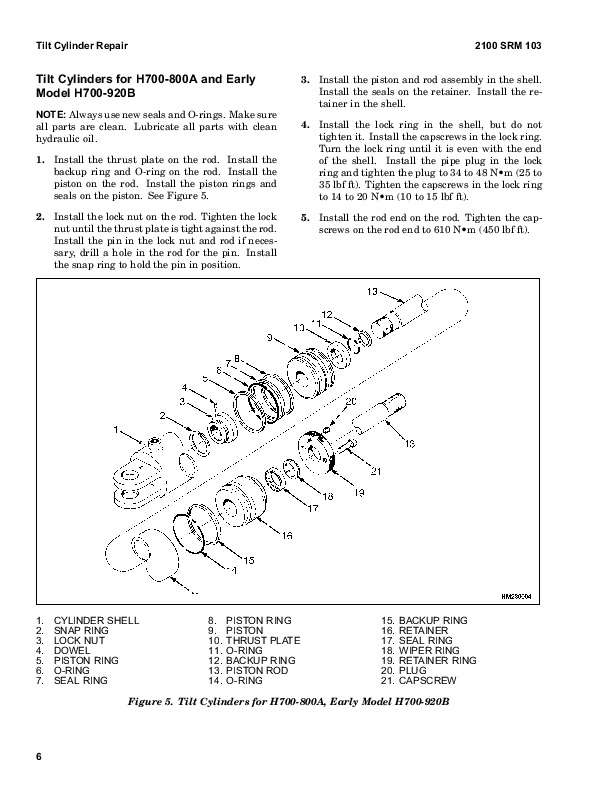
Tilt Cylinders for H700-800A and Early Model H700-920B….982
Install….983
Tilt Cylinders Using Chevron Packing….983
Install….984
Tilt Cylinder Leak Check….986
Tilt Cylinder Stroke and Mast Tilt Angle Adjustment….988
Torque Specifications….988
Piston Rod Nut….988
Retainer….989
Troubleshooting….991
tables….973
Table 1. Movement Rates (Maximum) for Tilt Cylinders….987
910442-8000SRM0231-(12-2004)-UK-EN….995
toc….995
Metric and Inch (SAE) Fasteners….995
Safety Precautions Maintenance and Repair….996
General….999
Threaded Fasteners….999
Nomenclature, Threads….999
Strength Identification….1000
Cotter (Split) Pins….1000
Fastener Torque Tables….1005
Conversion Table….1007
tables….995
Table 1. Bolts and Screws….1001
Table 2. Studs and Nuts….1002
Table 3. Torque Nuts….1003
Table 4. Torque Nuts With Nylon Insert….1004
Table 5. Torque Values for Metric Fasteners*….1005
Table 6. Torque Values for Inch Fasteners*….1006
Table 7. Conversion Table for Metric and English Units….1007
Table 8. Cotter Pin Dimensional Data….1008
Table 9. Cotter Pin Dimensional Data….1009
Table 10. Cotter Pin Dimensional Data….1010
Table 11. Cotter Pin Dimensional Data….1012
G019 (H300HD, H330HD, H360HD, H360HD-12EC)….1017
1494140-1600SRM0936-(03-2007)-US-EN….1018
toc….1018
Steering System….1018
Safety Precautions Maintenance and Repair….1019
General….1022
Description….1022
Steering Wheel and Column Assembly….1024
General….1024
Steering Wheel and Horn….1024
Remove….1024
Install….1024
Steering Control Unit Repair….1026
General….1026
Description….1026
Operation….1026
Remove….1027
Disassemble….1027
Clean….1030
Assemble and Install….1030
Steering System Air Removal….1036
Steering Relief Pressure Check….1037
Troubleshooting….1037
1494141-1800SRM0937-(03-2007)-US-EN….1042
toc….1042
Dry Brake System….1042
Safety Precautions Maintenance and Repair….1043
General….1046
Description….1046
Operation….1047
Service Brakes….1047
Parking Brake….1049
Air Tank Repair….1050
Relief Valve….1050
Drain Valve….1050
Brake Pedal Valve Repair….1051
Remove….1051
Disassemble, Inspect, and Assemble….1051
Install….1051
Air Chambers Repair….1052
Remove….1052
Disassemble….1052
Inspect….1053
Assemble….1054
Install….1054
Actuator Arms Repair….1054
Remove….1054
Inspect….1055
Install….1055
Brake Assemblies Repair….1056
Brake Shoe, Remove….1056
Camshaft, Remove….1058
Clean….1058
Inspect….1059
Camshaft, Install….1059
Brake Shoe, Install….1060
Air Dryer….1061
Description….1061
Cartridge….1061
Remove….1061
Install….1061
Filter….1061
Remove….1061
Install….1061
Quick-Release Valve….1063
Governor Check and Adjustment for Air Compressor….1063
Brake Shoes Adjustment….1064
Specifications….1065
Troubleshooting….1065
Service Brakes….1065
Service Brakes, Park Function ….1068
tables….1042
Table 1. Air Chambers Operation….1049
1494142-1900SRM0938-(03-2007)-US-EN….1072
toc….1072
Hydraulic System….1072
Safety Precautions Maintenance and Repair….1073
General….1076
Description and Operation….1076
Hydraulic Tank….1076
Hydraulic Pump….1077
Steering Priority Flow Valve….1077
Pilot Valve….1078
Main Control Valve….1080
Unloader Valve….1081
Hydraulic Operation….1082
Checks and Adjustments….1085
Quick Disconnect Fittings….1085
Steering Priority Flow Valve….1085
Steering Relief Pressure….1085
Modulator Valve….1086
Pilot Valve and Pressure Reducing Valve….1086
Accumulator….1087
Filter….1087
Main Control Valve….1087
Relief Pressure Check….1087
Check Valves….1088
Unloader Valve….1088
Hydraulic Pump Repair….1089
Remove….1089
Disassemble….1089
Clean and Inspect….1089
Assemble….1090
Install….1091
Pilot Accumulator Replacement ….1091
Remove….1091
Install….1091
Pilot Valve Repair….1092
Remove….1092
Disassemble….1093
Clean and Inspect….1093
Assemble….1093
Install….1093
Control Levers and Joystick Repair….1094
Remove….1094
Install….1094
Calibration and Diagnostics….1095
General….1095
Description….1095
Lever and Joystick Calibration….1095
Flow Adjustment….1095
Dead Band Value Setting….1096
Lowering Delay….1097
PWM and I/O Module Readouts….1097
Function Disable….1098
General Startup….1098
Minimum system requirements….1098
Install the Hydraulic Controls Program….1098
DelayTimeFile (Reset)….1098
Select the Processor Speed….1099
Hydraulic Controls Program….1099
Calibration….1101
Joystick/Lever Calibration….1101
Levers….1101
Joystick….1101
Valve Flow Adjustment….1102
Diagnostics….1102
Calibration System Shutdown….1102
LED Diagnostics….1103
Electrical Connections….1106
Specifications….1110
tables….1072
Table 1. Main Control Valve Port Settings….1078
Table 2. Processor Speed Settings….1098
Table 3. PWM Board LED Error Codes….1103
Table 4. Altering PT FLT I/O Board LED's (Old Logic)….1104
Table 5. Altering PT FLT I/O Board LED's (New Logic)….1104
Table 6. Fixed PT Logic I/O Boards LED's….1105
Table 7. ECH….1105
Table 8. PWM Driver Module….1106
Table 9. Input/Output Module 1….1107
Table 10. Input/Output Module 2….1108
Table 11. Altering PT FLT….1109
Table 12. Fixed PT FLT….1109
Table 13. ECH….1110
1494953-1400SRM0944-(03-2007)-US-EN….1114
toc….1114
Planetary Drive Axle….1114
Safety Precautions Maintenance and Repair….1115
General….1118
Description….1118
Operation….1120
Identification….1120
Removal….1121
Disassembly….1121
Planetary Spider and Gearing Assembly H8.00-12.00XM (H170-280HD)….1121
Planetary Spider and Gearing Assembly H13.00-14.00XM (H300-330HD….1123
Wheel End….1125
Spindle and Piston Housing….1126
Cleaning….1127
Clean Ground or Polished Parts….1127
Clean Parts With Rough Finish….1127
Clean Axle Assemblies….1127
Drying Cleaned Parts….1127
Corrosion Prevention….1127
Parts Inspection….1128
Tapered Roller Bearings….1128
Bevel Pinion and Ring Gear Sets….1129
Main Differential Assembly….1129
Axle Shafts….1129
Yoke….1129
Brakes….1129
Repair or Replace Parts….1129
Repair Welding….1129
Apply Silicone Gasket Material….1130
Assembly….1130
Spindle and Piston Housing to Axle Housing….1130
Wet Disc Brakes….1131
Adjust Wheel Bearing Preload….1132
Planetary Spider and Gearing Assembly H8.00-12.00XM (H170-280HD)….1133
Planetary Spider and Gearing Assembly H13.00-14.00XM (H300-330HD….1134
Planetary Spider Assembly….1134
Installation….1135
Fill Wet Disc Brakes With Hydraulic Fluid….1135
Torque Specifications….1136
Lubrication Specification….1137
1494955-2000SRM0943-(03-2007)-US-EN….1140
toc….1140
Main Control Valve….1140
Safety Precautions Maintenance and Repair….1141
General….1144
Description….1144
Operation….1147
Lift Section….1147
Tilt/Auxiliary Section….1147
Relief Valves….1147
Unloader Valve….1147
Main Control Valve Repair….1150
Remove….1150
Disassemble….1150
Auxiliary Side….1150
Lift Side….1150
Clean and Inspect….1153
Assemble….1153
Auxiliary Side….1153
Lift Side….1153
Install….1153
Pressure Relief Valve Check and Adjustment….1154
Check and Adjust….1154
Replace….1154
Specifications….1155
Troubleshooting….1155
1498445-1400SRM0945-(03-2007)-US-EN….1160
toc….1160
Planetary Drive Axle….1160
Safety Precautions Maintenance and Repair….1161
General….1164
Description….1164
Operation….1166
Identification….1166
Removal….1167
Disassembly….1167
Brake Drum….1167
Planetary Spider and Gearing Assembly H8.00-12.00XM (H170-280HD)….1168
Dry Brakes….1170
Planetary Spider and Gearing Assembly H13.00-14.00XM (H300-330HD….1170
Spindle and Brake Spider….1172
Cleaning….1173
Ground or Polished Parts….1173
Parts With Rough Finish….1173
Axle Assemblies….1173
Drying Cleaned Parts….1173
Corrosion Prevention….1173
Parts Inspection….1174
Tapered Roller Bearings….1174
Bevel Pinion and Ring Gear Sets….1175
Main Differential Assembly….1175
Axle Shafts….1175
Yoke….1175
Brakes….1175
Repair or Replace Parts….1175
Repair Welding….1175
Apply Silicone Gasket Material….1176
Assembly….1176
Spindle, Brake Spider, and Brake….1176
Wheel End….1177
Adjust Wheel Bearing Preload….1178
Planetary Spider and Gearing Assembly H8.00-12.00XM (H170-280HD)….1179
Planetary Spider and Gearing Assembly H13.00-14.00XM (H300-330HD….1180
Planetary Spider Assembly….1180
Installation….1181
Torque Specifications….1182
Lubrication Specification….1183
1498450-1800SRM0951-(03-2007)-US-EN….1186
toc….1186
Wet Brake System….1186
Safety Precautions Maintenance and Repair….1187
General….1190
Description and Operation….1190
Service Brakes….1190
Parking Brake….1190
Oil Cooler Circuit….1190
Pressure Switch Replacement….1194
Accumulators Replacement….1194
Brake Treadle Valve Repair….1194
Remove and Disassemble….1194
Clean and Inspect….1195
Assemble and Install….1195
Parking Brake Valve Repair….1195
Remove….1195
Clean and Inspect….1195
Repair….1195
Install….1195
Parking Brake Caliper Repair….1196
Remove….1196
Disassemble….1198
Inspect….1198
Install….1198
Adjust….1198
Brake Pad Repair….1199
Inspect….1199
Remove….1199
Install….1199
Seals Repair….1199
Remove….1199
Install….1200
Service Brake Repair….1200
Remove and Disassemble….1200
Drain Lubricating Oil….1200
Drain Coolant Oil….1207
Disconnect Brake Lines….1207
Wheel End With Outer Bearing on Ring Gear Hub Journal H13.00-14….1207
Wheel End With Outer Bearing on Spindle Journal H8.00-12.00XM (H….1208
Brake Disc Housing Assembly Wheel End….1209
Brake Piston Housing….1210
Brake Piston Housing and Wheel Spindle….1211
Inspect….1211
Clean….1213
Assemble….1214
Wheel Spindle….1214
Brake Piston Housing….1214
Piston Assembly….1216
Brake Disc Housing….1216
Duo-Cone Face Seal Into Brake Disc Housing and Into Hub….1218
Check for Correct Installation of Duo-Cone Seal….1219
Wheel Hub to Brake Disc Housing….1220
Adjust….1221
Fill Brake System With Coolant Oil….1221
System Air Removal….1222
Adjust Brake With New Disc Pack….1222
Coolant Change Intervals….1223
Coolant Draining and Filling….1223
Specifications….1225
Minimum Brake Disc Thickness….1228
Hydraulic Fluid for Brake Actuation….1228
Brake Coolant Specifications….1228
Coolant Change Intervals….1228
Hydraulic Fluid Specifications….1228
Troubleshooting….1228
Brake Does Not Apply….1228
Brake Does Not Release….1229
Brake Performance….1229
Brake Leaks Actuation Fluid….1230
Brake Cooling Fluid Leakage….1231
Brake Noise and Vibration….1231
Brake Overheats….1231
tables….1186
Table 1. Brake Pad Adjustment….1198
Table 2. Minimum Brake Disc Thickness….1212
Table 3. Formed Seal Wear Chart….1212
1503241-5000SRM0969-(10-2007)-US-EN….1236
toc….1236
Empty Container Handling Attachment….1236
Safety Precautions Maintenance and Repair….1237
General….1240
Description….1240
Operation….1246
General….1246
Selector Valves….1246
Sideshift Circuit….1246
Extend and Retract Circuit….1246
Twist Lock Circuit and Control….1247
Model 553 – Horizontally Mounted….1247
Model 558 – Vertically Mounted….1247
Lifting Hooks….1247
Model 555….1247
Indicator Lights and LEDs….1247
Lift Interrupt and Override….1248
Overlowering Interrupt and Override….1248
Carriage and Attachment Repair….1248
Remove….1248
Attachment Without Carriage Repair….1249
Remove….1249
Sideshift Cylinders Repair….1250
Remove….1250
Disassemble….1250
Assemble….1250
Extension Cylinders Repair….1251
Remove….1251
Disassemble….1251
Clean and Inspect….1251
Assemble….1251
Install….1251
Vertical End Beams Repair….1253
Remove….1253
Install….1253
Hose Replacement in End Beams….1253
Twist Locks Repair for Model 553….1254
Remove….1254
Disassemble….1254
Clean and Inspect….1254
Assemble….1254
Hooks Replacement for Model 555….1255
Inspect….1255
Remove….1255
Install….1255
Twist Locks Repair for Model 558….1256
Disassemble….1256
Clean and Inspect….1256
Assemble….1256
Bleed the System….1257
Valve Assembly….1257
Slide Pad Replacement….1258
Adjustments….1258
Twist Lock Angle Adjustment….1258
Model 558 Only….1258
LOCKED/NOT LOCKED Sensors Adjustment….1259
Model 553….1259
Model 558….1259
Seated Sensor Adjustment….1259
Model 553….1259
Model 558….1259
Overlowering Protection Sensor Adjustment (Models 553 and 558)….1259
Torque Chart….1260
Maintenance….1260
Additional Attachment Maintenance….1262
Interface Boxes….1263
Model 555….1263
Models 553 and 558….1263
Troubleshooting….1265
tables….1236
Table 1. Torque Chart….1260
Table 2. Inspect and Adjust (See Figure 14 )….1261
Table 3. Lubricate (See Figure 14 )….1262
Table 4. Replace (See Figure 14 )….1262
1553599-4000SRM1062-(03-2007)-US-EN….1282
toc….1282
Masts and Carriages….1282
Safety Precautions Maintenance and Repair….1283
General….1286
Description….1286
Operation….1287
Two-Stage Mast….1287
Three-Stage Mast….1288
Safety Procedures When Working Near Mast….1289
Forks Repair….1292
Remove….1292
Inspect and Adjust….1292
Install….1292
Carriage Repair….1293
Description….1293
Three Function….1293
Four to Six Function….1293
Remove….1293
Disassemble….1294
Clean and Inspect….1296
Assemble….1296
Install….1296
Sideshift Cylinder Repair….1297
Remove….1297
Disassemble….1297
Clean and Inspect….1297
Assemble….1297
Install….1297
Fork Positioner Cylinders Repair….1301
Remove….1301
Disassemble….1301
Clean and Inspect….1301
Assemble….1301
Install….1301
Directional Control Valve Repair….1308
Remove….1308
Disassemble….1308
Clean and Inspect….1308
Assemble….1309
Install….1309
Mast Repair….1309
Two- and Three-Stage Mast….1309
Remove….1309
Disassemble….1314
Clean and Inspect….1316
Assemble….1317
Install….1318
Three-Stage Mast (Four Cylinders)….1318
Remove….1318
Disassemble….1320
Clean and Inspect….1322
Assemble….1322
Install….1322
Fork Carriage Chains….1324
Adjust….1324
Bearing Rollers….1326
Description….1326
Lubrication….1326
Clearance….1326
Remove and Disassemble….1326
Assemble….1327
Mast Profile….1327
Lift Cylinders Description….1327
Piston-Type Cylinders….1327
Displacement-Type Cylinders….1327
Lift Cylinders Repair….1328
Remove….1328
Disassemble….1330
Clean and Inspect….1330
Assemble….1330
Install….1331
Mast Operation Check….1331
Lift and Tilt System Leak Checks….1332
Lift System….1332
Tilt System….1332
Tilt Cylinder Stroke and Backward Tilt Angle Adjustment….1333
Lift Chain Adjustments….1333
Mast Adjustments….1334
Bearing Blocks, Two-Stage Masts….1334
Wear Plates….1334
Carriage Adjustment….1334
Troubleshooting….1336
tables….1282
Table 1. Allowable Mast Movement from Internal Leakage….1332
1556871-2200SRM1105-(03-2007)-US-EN….1340
toc….1340
Instrument Panel Indicators and Senders….1340
Safety Precautions Maintenance and Repair….1341
General….1344
Description….1344
General….1344
Instrument Panel Meters, Indicators, and LCD Display….1344
Connector….1350
Seat Switch Logic….1351
Central Warning Light Output….1351
Buzzer Output….1351
Instrument Panel….1353
Remove….1353
Sender Replacement….1354
Fuel Level Sender (Diesel Engine Only)….1354
Engine Oil Pressure Sender….1355
Brake Pressure Sender….1355
Low Coolant Sender….1355
Vacuum Switch….1355
Specifications….1356
Troubleshooting….1357
tables….1340
Table 1. Instrument Panel and Indicators….1345
Table 2. Pin Description….1350
Table 3. Sender Description….1351
1564053-0600SRM1101-(11-2007)-US-EN….1362
toc….1362
Cummins Diesel/LPG Engine Fault Code Guide….1362
Safety Precautions Maintenance and Repair….1363
General….1366
Fault Codes….1366
Normal Mode….1366
Fault Log Mode….1366
Access….1366
Exit….1367
Clear….1367
Electronic Throttle Calibration….1367
Electronic Throttle Calibration Procedure….1367
tables….1362
Table 1. Error Code Descriptions….1368
1586990-8000SRM1181-(03-2007)-US-EN….1384
toc….1384
Assembly Guide….1384
Safety Precautions Maintenance and Repair….1385
List of All Special Tools and Equipment Needed for the Assembly….1388
General Considerations Before Starting the Job….1388
Preparation of the Components Before Assembly….1389
Liquefied Petroleum Gas (LPG Engines Only)….1389
Remove….1389
Install….1390
Checking of the Wheels….1390
Air Pressure….1390
Drive Wheels….1391
Steer Wheels….1395
Wheel Nut Torque….1398
Mast Label Placement….1399
Safety Procedures When Working Near Mast….1400
Mast Installation….1402
Mast….1402
Tilt Cylinder Pin Installation….1405
Lift Cylinder Hose Connection….1406
Truck Header Hoses and Electrical Cable Connections….1407
Mast Light Connection….1409
Carriage Installation….1410
Carriage Header Hoses and Electrical Cable Connection….1411
Fork Installation….1414
Exhaust Extension Tube Installation….1415
Lights Installation – Operator Compartment….1417
Hydraulic Oil Check….1418
Lubrication Points….1419
Check Points….1420
Checkpoint 1….1420
Checkpoint 2….1420
Checkpoint 3….1420
Checkpoint 4….1420
Checkpoint 5….1420
General Truck Install Procedures….1420
tables….1384
Table 1. Mast Hanger Pins Capscrew Torques….1405
1663926-8000SRM1346-(05-2007)-US-EN….1424
toc….1424
Diagrams….1424
Safety Precautions Maintenance and Repair….1425
1663927-8000SRM1347-(12-2007)-US-EN….1478
toc….1478
Periodic Maintenance….1478
Safety Precautions Maintenance and Repair….1479
General….1484
Serial Number Data….1484
How to Move a Disabled Lift Truck….1485
How to Tow the Lift Truck….1485
How to Put a Lift Truck on Blocks….1485
How to Raise the Drive Tires….1486
How to Raise the Steer Tires….1486
Maintenance Schedule….1487
Empty Container Attachment Maintenance….1494
Maintenance Procedures Every 8 Hours or Daily….1496
How to Make Checks With the Engine Stopped….1496
Safety Labels….1496
Tires and Wheels….1496
Inspection of Forks, Mast, and Lift Chains….1497
Header Hose Assembly….1498
Forks, Adjust….1498
Forks, Remove….1498
Forks, Install….1498
Precleaner for Air Filter….1499
Check for Fuel, Oil, or Coolant Leaks….1499
Coolant Hoses….1499
Engine Air Intake Piping….1499
Drive Belts….1499
Radiator Sections for Engine Coolant, Charge Air Cooler, and Hyd….1500
Engine Compartment….1500
Operator Restraint System (Seat Belt and Seat Rails)….1500
Steering Column Latch….1500
Hydraulic System Oil….1500
Windshield Washer Fluid….1501
Engine Oil….1501
How to Add Fuel to the Lift Truck….1503
Diesel Fuel….1503
Liquefied Petroleum Gas (LPG)….1504
Remove….1504
Fill….1504
Install….1505
How to Make Checks With the Engine Running….1505
Gauges, Lights, Horn, Fuses, and Relays….1505
Engine and Transmission Fault Codes….1508
Cooling System….1508
Diesel Fuel Filter/Water Separator….1509
Electrical System….1509
Engine Oil Pressure….1509
Fuel System….1509
Engine Air Filter….1509
Control Levers and Pedals….1509
Steering System….1509
Parking Brake….1509
Service Brakes….1510
Lift System Operation….1510
Transmission….1510
Transmission Oil….1510
First Inspection After First 100 Hours of Operation….1511
Lift Chains….1511
Hydraulic System Oil Filter….1511
Engine Oil Filter….1511
Transmission Oil Filter….1512
Hydraulic Pilot Valve Oil Screen….1512
Wet Brake System Filter….1512
First Inspection After First 500 Hours of Operation….1512
Cab Mounting Bolts….1512
Maintenance Procedures Every 250 Hours or Monthly….1513
Twist Locks….1513
Lifting Hooks (Model 555)….1513
Empty Container Attachment….1513
Maintenance Procedures Every 250 Hours or 3 Months….1513
Lift Chains….1513
Wheel Nuts….1514
Forks….1514
LPG Crankcase Breather….1514
Mast Bearing Block Surfaces and Strip Bearings….1514
Sideshift Carriage Sliding Surfaces….1515
Fork Pins and Guides….1515
Maintenance Procedures Every 500 Hours or 3 Months….1515
Rod Ends at Sideshift Cylinder….1515
Mast Pivot Pins….1515
Tilt Cylinder Pivot Pins….1515
Steering Axle Tie Rod Pins….1515
King Pins….1515
Shafts for Air Brake Actuator Arms….1515
Drive Shaft….1515
Maintenance Procedures Every 500 Hours or 6 Months….1516
Cab Air Filter….1516
Planetary Drive Axle and Differential….1516
Header Hose Assembly….1516
Hydraulic Tank Breather….1516
Air Compressor (Air Brakes Only)….1516
Spark Plug Wire (LPG Engine Only)….1516
Cooling Fan….1516
Drive Belts….1516
Coolant….1516
Fuel Pump….1516
Engine Oil….1517
Engine Oil Filter….1517
Diesel Fuel Filter….1517
Maintenance Procedures Every 1000 Hours or 6 Months….1517
Extension Cylinder Support Wear Pads (ECH Only)….1517
Brake Accumulator (Wet Brake Only)….1517
Coolant Fan Belt Tensioner….1517
Fan Hub….1519
Pilot Valve Accumulator….1519
LPG Tank Hinges….1520
Cab Door Hinges….1520
LPG Vapor Fuel Filter….1520
Wet Brake System Filter….1520
Maintenance Procedures Every 1000 Hours or 1 Year….1521
Engine Valve Adjustment….1521
Diesel Fuel Filter/Water Separator….1521
Transmission Oil….1521
Transmission Oil Filter….1521
Transmission Breather….1521
Maintenance Procedures Every 1500 Hours or 6 Months….1521
Drive Axle and Differential….1521
Maintenance Procedures Every 2000 Hours or 1 Year….1521
Transmission Calibration….1521
Inching Pedal Sensor Calibration….1521
Parking and Service Brakes….1521
Vibration Damper….1522
Engine and Transmission Isolators….1522
Engine Air Intake Piping….1522
Brake Air Pressure Lines….1522
Spark Plug (LPG Engines Only)….1523
LPG Liquid Fuel Filter….1523
Maintenance Procedures Every 3000 Hours or 1 Year….1524
Pedals, Levers, Seat Rails, and Hinges….1524
Air Dryer Cartridge….1524
Hydraulic System Oil and Filter….1524
Maintenance Procedures Every 3000 Hours or 2 Years….1525
Hydraulic Pilot Valve Oil Screen….1525
Maintenance Procedures Every 4000 Hours or 2 Years….1525
Spark Plug Wire (LPG Engines Only)….1525
Steer Wheels Hub Bearings….1525
Maintenance Procedures Every 5000 Hours….1526
Twist Locks or Hooks….1526
Maintenance Procedures Every 5000 Hours or 3 Years….1526
Air Conditioning….1526
Maintenance Procedures Every 6000 Hours or 2 Years….1526
Turbocharger….1526
Maintenance Procedures Every 12,000 Hours or 5 Years….1527
Cooling System….1527
Safety Procedures When Working Near Mast….1528
Lift and Tilt System Leak Check….1529
Lift System….1529
Tilt System….1529
Wheel and Tire Replacement….1530
Remove Wheels From Lift Truck….1530
Pneumatic Tires….1531
Remove Tire From Wheel….1531
Remove Tire From Two- and Four-Piece Wheel….1531
Install Tire on Wheel….1532
Install Tire on Two- and Four-Piece Wheel….1533
Add Air to Tires….1534
Solid Rubber Tires….1534
Remove Tire From Wheel….1534
Install Tire on Wheel….1536
Wheels, Install….1537
tables….1478
Table 1. Daily Inspections − Condition Check….1488
Table 2. Daily Inspections − Fluid Level Check….1489
Table 3. Daily Inspections − Checks With the Engine Running….1489
Table 4. Initial 100-Hour Check or Change….1490
Table 5. Initial 500-Hour Check or Change….1490
Table 6. Periodic Maintenance Schedule − Inspect and Adjust….1491
Table 7. Periodic Maintenance Schedule − Lubricate….1492
Table 8. Periodic Maintenance Schedule − Change….1493
Table 9. Empty Container Attachment Maintenance − Inspect and ….1495
Table 10. Empty Container Attachment Maintenance − Lubricate….1495
Table 11. Empty Container Attachment Maintenance − Replace….1495
Table 12. Approved LPG Engine Oil Types….1503
Table 13. Valve Adjustment Specifications….1521
Table 14. Allowable Mast Movement from Internal Leakage….1530
1663928-8000SRM1348-(03-2008)-US-EN….1540
toc….1540
Capacities and Specifications….1540
Safety Precautions Maintenance and Repair….1541
Counterweight Weights….1544
Lift Truck Weights….1544
Capacities….1545
Engine Specifications….1546
Hydraulic System….1547
Electrical System….1547
Tire Sizes….1547
Mast Speeds….1548
Torque Specifications, Cummins Diesel….1548
Lubrication System….1548
Torque Specifications, General….1549
Transmission….1549
Driveline and Axle….1549
Counterweight….1549
Differential….1549
Brakes – Wet….1549
Brakes – Dry….1549
Steering….1549
Wheel Nuts….1549
Hydraulic System….1550
Mast….1550
Carriage….1550
Tilt Cylinders….1550
Wiper Arms, Front….1550
1665777-0100SRM1349-(01-2008)-US-EN….1554
toc….1554
Frame….1554
Safety Precautions Maintenance and Repair….1555
General….1558
Description….1558
Air Cleaner….1559
Remove….1559
Install….1559
Exhaust System….1560
Remove….1560
Install….1560
Hood Assembly….1561
Remove….1561
Install….1562
Hydraulic Tank….1562
Remove….1562
Inspect….1564
Clean….1564
Additional Preparations for Repair….1565
Repair….1565
Small Leaks….1565
Large Leaks….1565
Preparations for use After Repair….1565
Install….1566
Fuel Tank….1567
Remove….1567
Repair….1571
Install….1571
Engine….1572
Remove….1572
Install….1577
Counterweight….1578
General….1578
Remove….1579
Install….1580
Label Replacement….1580
tables….1554
Table 1. Counterweight Weights….1578
1665778-0700SRM1350-(03-2007)-US-EN….1584
toc….1584
Multiple Aligned Cooling System….1584
Safety Precautions Maintenance and Repair….1585
General….1588
Description….1589
Radiator….1589
Radiator Cap….1589
Thermostat….1589
Water Pump….1590
Fan and Fan Shroud….1590
Cooling System Checks….1590
Radiator….1590
Thermostat….1590
Water Pump….1591
Exhaust Leaks….1591
Fan and Fan Shroud….1591
Cooling System Repair….1592
Remove….1592
Install….1593
Core Repair….1594
Remove….1594
Install….1594
Radiator Cleaning….1594
Drain….1594
Clean….1594
Fill….1595
Troubleshooting….1595
1665779-2200SRM1351-(04-2007)-US-EN….1600
toc….1600
Electrical System….1600
Safety Precautions Maintenance and Repair….1601
Description….1604
Warning Devices….1609
General….1609
Description….1610
Operator-Controlled Horn….1610
Reverse Warning Horns/Lights….1610
Warning Lights….1610
Strobe Light….1610
Brake Lights….1612
Hazard Lights….1612
Replace….1612
General….1612
Horns….1612
Horn Relay….1612
Light Assemblies….1612
Flashing Unit….1613
Meters, Senders, and Switches….1613
General….1613
1670739-1300SRM1356-(07-2008)-US-EN….1626
toc….1626
Transmission….1626
Safety Precautions Maintenance and Repair….1627
General….1630
Transmission Repair….1630
Remove….1630
Disassemble….1634
Transmission Case, Disassemble….1635
Torque Converter Housing, Disassemble….1652
Forward Clutch, Disassemble….1657
First-Speed Clutch, Disassemble….1659
Reverse and Second-Speed Clutch….1664
Reverse Clutch, Disassemble….1664
Second-Speed Clutch, Disassemble….1669
Third-Speed Clutch, Disassemble….1671
Third Clutch Shaft, Disassemble….1673
Turbine Shaft, Disassemble….1674
Output Shaft, Disassemble….1675
Impeller, Disassemble….1676
Turbine, Disassemble….1678
Clean and Inspect….1680
Housings….1680
Oil Seals and Gaskets….1680
Bearings….1681
Gears and Shafts….1681
Assemble….1681
Turbine, Assemble….1681
Impeller, Assemble….1683
Output Shaft, Assemble….1685
Turbine Shaft, Assemble….1687
Third Clutch Shaft, Assemble….1688
Third-Speed Clutch, Assemble….1689
Reverse and Second-Speed Clutch….1692
Second-Speed Clutch, Assemble….1692
Reverse Clutch, Assemble….1695
First-Speed Clutch, Assemble….1699
Forward Clutch, Assemble….1704
Torque Converter Housing, Assemble….1707
Transmission Case, Assemble….1712
Install….1733
Control Valve Removal and Installation….1735
Remove….1735
Install….1735
Control Valve Disassemble and Assemble….1737
Remove….1737
Transmission Frame Bracket….1737
Control Valve Cover….1737
Control Valve Components….1737
Install….1739
Control Valve Components….1739
Control Valve Cover….1739
Transmission Frame Bracket….1739
Torque Specifications….1740
Torque Specifications for Lubricated or Plated Screw Threads….1740
Troubleshooting….1742
tables….1626
Table 1. Grade 5….1740
Table 2. Grade 8….1740
Table 3. Grades 8.8, 10.9, and 12.9….1741
Table 4. O-ring Port Plug Torque Chart….1742
Table 5. Pipe Plug Torque Chart….1742
1671895-1300SRM1358-(07-2008)-US-EN….1746
toc….1746
Transmission….1746
Safety Precautions Maintenance and Repair….1747
General….1752
Description….1752
General….1752
Operation….1755
Hydraulic Operation….1755
1st/3rd Selector Valve….1757
Cooling and Lubrication….1757
Control System….1759
General….1759
APC200 Controller….1759
Self Test….1759
Protection Modes….1759
Limp Home Mode….1759
Shut Down Mode….1759
Transmission Exceed Codes….1759
Fault Codes….1760
Description….1760
Fault Log Mode….1760
Access….1760
Exit….1760
Clear….1761
Fault Rectification….1761
Hydraulic Control Valve….1762
Hydraulic Control Valve Repair….1763
Solenoid Replacement….1763
Pressure Check….1764
Pressure Specifications….1764
Pressure, Speed, and Temperature Sensors….1765
Pressure Switch….1769
Test….1769
Speed Sensor….1769
Test….1770
Temperature Sensors….1771
Test….1771
Transmission Test and Calibration….1771
Precautions….1771
Stall Test….1771
Description….1771
Stall Test Procedure….1771
Clutch Calibration….1772
Description….1772
Procedure….1773
Inching Calibration….1773
Description….1773
Brake and Inching Pedal Adjustment….1774
Inching Sensor Adjustment….1774
Inching Sensor Calibration….1775
Electrical Specifications….1775
APC200 Operation….1776
General….1776
General Information Group….1776
Fault Codes….1777
Indication of Protection Modes….1777
Test Function Group….1778
Digital Input Test….1779
Analog Input Test….1780
Speed Sensor Test….1780
Output Test….1781
Voltage Test….1782
Calibration Group….1782
Calibration Mode….1782
Clutch Filling Calibration….1783
Heat Up Mode….1783
Inching Sensor Calibration….1784
Inching Pedal Sensor Adjustment….1784
Inching Sensor Calibration….1784
TE-Userlink….1785
Description….1785
Connection….1785
Table 12. Transmission Exceed Codes….1818
Table 13. APC200 Fault Codes….1818
Table 14. Common Calibration Condition Messages….1829
Table 15. Fault Codes During Clutch Calibration….1830
tables….1746
Table 1. Activated Solenoids and Gear Selection….1757
Table 2. Control Valve Pressure Check Ports….1762
Table 3. Transmission Housing Check Ports….1768
Table 4. Sensors and Switches….1769
Table 5. Speed Sensor Check Values….1770
Table 6. Temperature Sensor (In Speed Sensor) Resistance Versus ….1775
Table 7. General Information Group….1777
Table 8. Digital Input Test….1779
Table 9. Analog Input Test….1780
Table 10. Speed Sensor Test….1781
Table 11. Output Test….1781
1689543-0100SRM1383-(09-2008)-US-EN….1834
toc….1834
Operator's Cab….1834
Safety Precautions Maintenance and Repair….1835
General….1842
Description of Operation….1843
Cab Structure….1843
Cab Supporting Frame….1843
Cab Tilt Cylinder….1845
Extending the Cab Tilt Cylinder….1845
Retracting the Cab Tilt Cylinder….1846
Heater System….1846
Air Conditioning….1848
General….1848
Dryer….1849
Control Systems, Sensors, and Switches….1849
Oil Filling for Cab Tilt System….1850
Raising and Lowering Cab….1851
Raise Cab….1851
Lower Cab….1852
Cab….1852
Remove….1852
Install….1854
Cab Door Assembly….1855
Cab Door….1855
Remove….1855
Install….1855
Door Hinge….1855
Remove….1855
Install….1855
Door Latch….1855
Remove….1855
Install….1856
Door Handle….1857
Remove….1857
Install….1857
Door Release….1857
Remove….1857
Install….1857
Door Pushbutton….1857
Remove….1857
Install….1857
Cab Tilt System….1857
Electric Tilt Pump….1857
Remove….1857
Install….1858
Hand Pump….1858
Remove….1858
Install….1858
Cab Tilt Cylinder….1858
Remove….1858
Disassemble….1858
Clean….1860
Inspect….1860
Assemble….1860
Install….1861
Latch….1861
Remove….1861
Install….1861
Brake and Inching Pedals….1862
Brake and Inching Pedals….1862
Remove….1862
Install….1862
Brake Pedal Adjustment….1862
Dry Brake….1862
Wet Brake….1862
Inching Pedal Adjustment….1863
Dry Brake….1863
Wet Brake….1863
Inching Pedal Sensor Adjustment Using Userlink® Program….1863
Inching Pedal Sensor Calibration Procedure Using Userlink® Progr….1864
Inching Pedal Sensor Adjustment Using the APC200….1864
Inching Pedal Sensor Calibration Procedure Using the APC200….1865
Accelerator Pedal Sensor….1866
Check….1866
Adjust….1866
Seat Assembly….1867
Seat….1867
Remove….1867
Install….1867
Seat Cushion….1867
Remove….1867
Install….1867
Back Cushion….1868
Remove….1868
Install….1868
Seat Suspension….1868
Remove….1868
Install….1868
Boot….1868
Remove….1868
Install….1868
Shock Absorber….1868
Remove….1868
Install….1868
Compressor….1869
Remove….1869
Install….1873
Power Assist Armrest….1879
Release Cable….1879
Remove….1879
Install….1879
Gas Spring….1879
Remove….1879
Install….1879
Armrest Assembly….1880
Adjust….1880
Joystick….1880
Remove….1880
Install….1880
Levers….1881
Remove….1881
Install….1881
Rocker Switches….1881
Remove….1881
Install….1881
Cover….1881
Remove….1881
Install….1881
Instrument Panel….1882
Key Switch….1882
Remove….1882
Install….1882
12V Power Socket….1882
Remove….1882
Install….1882
Electric-Operated Heater Control and Fan Control….1883
Remove….1883
Install….1883
Cable-Operated Heater Control and Air Control….1884
Remove….1884
Install….1884
Air Conditioning Switch….1884
Remove….1884
Install….1884
Rocker Switches….1884
Remove….1884
Install….1884
Parking Brake Switch….1885
Remove….1885
Install….1885
Indicator Display….1885
Remove….1885
Install….1885
Instrument Panel Top Console….1886
Remove….1886
Install….1886
Steering Wheel and Column Assembly….1886
Steering Wheel and Horn….1886
Remove….1886
Install….1886
Steering Column Assembly….1888
Remove….1888
Install….1889
Adjustment Mechanism….1889
Remove….1889
Install….1889
Main Warning Lights….1889
Remove….1889
Install….1889
Shift Lever….1890
Remove….1890
Install….1890
Turn Signal Lever….1890
Remove….1890
Install….1890
Window Wipers Replacement….1891
Window Wiper Assembly, Replace….1891
Remove….1891
Install….1891
Window Wiper Motor Replacement….1892
Front Window Wiper Motor Assembly….1892
Remove….1892
Install….1892
Rear Window Wiper Motor Assembly….1892
Remove….1892
Install….1892
Top Window Wiper Motor Assembly….1893
Remove….1893
Install….1893
Window Washer System….1893
Window Washer Reservoir….1893
Remove….1893
Install….1893
Window Washer Motors and Pumps….1893
Remove….1893
Install….1894
Window Washer Hoses….1894
Top/Rear….1894
Remove….1894
Install….1895
Front….1895
Remove….1895
Install….1896
Window Washer Nozzles….1896
Front….1896
Remove….1896
Install….1896
Rear….1896
Remove….1896
Install….1897
Top….1897
Remove….1897
Install….1897
Window Replacement….1897
Front Window….1899
Remove….1899
Install….1899
Rear Window….1899
Remove….1899
Install….1899
Top Window….1900
Remove….1900
Install….1900
Door Window….1900
Upper/Lower Window….1900
Remove….1900
Install….1900
Sliding Window….1900
Front Sliding Window….1900
Remove….1900
Install….1902
Rear Sliding Window….1902
Remove….1902
Install….1902
Weather Strip, Replace….1903
Window Stopper, Replace….1903
Sliding Tracks, Replace….1903
Window Seals, Replace….1903
Sliding Window Frame….1903
Remove….1903
Install….1903
Heater System Repair….1904
Heater Assembly….1904
Access….1904
Remove….1904
Install….1905
Heater Assembly Parts, Replace….1905
Heater Core….1905
Remove….1905
Install….1906
Evaporator Core….1906
Remove….1906
Install….1906
Blower….1907
Remove….1907
Install….1907
Water Valve….1907
Remove….1907
Install….1908
Vent Door….1908
Remove….1908
Install….1908
Push/Pull Cable, Replace….1909
Water Valve Cable….1909
Remove….1909
Install….1909
Vent Door Cable….1910
Remove….1910
Install….1910
Floor Mat….1911
Front….1911
Remove….1911
Install….1912
Rear….1912
Remove….1912
Install….1912
Radio Console….1913
Remove….1913
Install….1913
Air Duct….1913
Front….1913
Remove….1913
Install….1913
Rear….1914
Remove….1914
Install….1914
Accessories….1915
Mirror….1915
Remove….1915
Install….1915
Sunshade….1915
Top….1915
Remove….1915
Install….1915
Rear….1915
Remove….1915
Install….1916
Map Light….1916
Remove….1916
Install….1916
Interior Fan….1916
Remove….1916
Install….1916
Training Seat….1916
Install….1916
Remove….1916
Air Conditioning Technical Detail….1917
Technical Detail….1917
Label Replacement….1918
tables….1834
Table 1. Air Conditioning Specifications….1917
897108-1600SRM0326-(03-2007)-US-EN….1922
toc….1922
Steering Axle….1922
Safety Precautions Maintenance and Repair….1923
General….1926
Description….1926
Steering Axle Assembly Repair….1931
Steering Axle H3.50-5.00XL (H70-110XL) (G005), S3.50-5.50XL (S70….1931
Remove….1931
Install….1931
Steering Axle H6.00-7.00XL (H135-155XL, H135-155XL 2 ) (F006, G0….1932
Remove….1932
Install….1932
Wheels and Hubs Repair (All Units)….1933
Remove and Disassemble….1933
Clean….1933
Inspect….1933
Assemble and Install….1933
Spindles and Bearings Repair (All Units)….1935
Remove….1935
Clean….1935
Assemble and Install….1936
Tie Rods Repair (All Units)….1937
Remove….1937
Clean….1937
Install….1937
Steering Cylinder Repair….1940
Remove and Disassemble….1940
Clean and Inspect….1940
Assemble and Install….1940
Troubleshooting….1941
910072-1400SRM0046-(07-2007)-US-EN….1946
toc….1946
Differential….1946
Safety Precautions Maintenance and Repair….1947
General….1950
Description….1950
Differential Repair….1951
Remove….1951
Differential Carrier From Axle Housing, Remove….1951
Differential and Ring Gear From Differential Carrier, Remove….1953
Drive Pinion and Pinion Carrier From Differential Carrier, Remov….1955
Disassemble….1956
Differential and Ring Gear Assembly, Disassemble….1956
Drive Pinion and Pinion Carrier, Disassemble….1958
Clean and Inspect….1961
Assemble….1962
Pinion, Bearings, and Pinion Carrier, Assemble….1962
Pinion Bearings, Adjust Preload….1962
Press Method….1962
Yoke or Flange Method….1963
Triple-Lip Seal, Install….1964
Pinion Carrier Shim Set, Adjust Thickness (Depth of Pinion)….1965
Differential and Ring Gear, Assemble….1967
Differential Gears Rotating Torque, Check….1969
Differential and Ring Gear Assembly, Install….1970
Differential Bearings, Preload Adjust….1972
Ring Gear, Runout Check….1973
Ring Gear Backlash, Adjust….1973
Gear Set, Tooth Contact Pattern Check….1975
Thrust Screw, Install and Adjust….1978
Install….1978
Differential Assembly Into Axle Housing, Install….1978
Specifications….1980
Troubleshooting….1985
tables….1946
Table 1. Ring Gear Backlash Adjustment Specifications….1975
Table 2. Ring and Pinion Tooth Contact Adjustment….1976
Table 3. General Specifications….1980
Table 4. Rivet Installation Pressure….1980
Table 5. Pinion Adjustment….1981
Table 6. Pinion Preload Pressure….1981
Table 7. Torque Specifications….1982
Table 8. Torque Specifications for Metric Hardware….1983
Table 9. Torque Specifications for Metric (Fine) Hardware….1984
910102-2100SRM0103-(03-2007)-US-EN….1988
toc….1988
Tilt Cylinders….1988
Safety Precautions Maintenance and Repair….1989
General….1992
Description….1992
Tilt Cylinder Repair….1992
Remove….1992
Disassemble….1992
Clean….1992
Assemble….1992
Tilt Cylinders With O-Ring or Single-Lip Seals….1992
Tilt Cylinders for XM and XMS Models….1994
Tilt Cylinders for XL, XLS, and XL 3 Models….1995
Tilt Cylinders for H700-800A and Early Model H700-920B….1997
Install….1998
Tilt Cylinders Using Chevron Packing….1998
Install….1999
Tilt Cylinder Leak Check….2001
Tilt Cylinder Stroke and Mast Tilt Angle Adjustment….2003
Torque Specifications….2003
Piston Rod Nut….2003
Retainer….2004
Troubleshooting….2006
tables….1988
Table 1. Movement Rates (Maximum) for Tilt Cylinders….2002
910442-8000SRM0231-(12-2004)-US-EN….2010
toc….2010
Metric and Inch (SAE) Fasteners….2010
Safety Precautions Maintenance and Repair….2011
General….2014
Threaded Fasteners….2014
Nomenclature, Threads….2014
Strength Identification….2015
Cotter (Split) Pins….2015
Fastener Torque Tables….2020
Conversion Table….2022
tables….2010
Table 1. Bolts and Screws….2016
Table 2. Studs and Nuts….2017
Table 3. Torque Nuts….2018
Table 4. Torque Nuts With Nylon Insert….2019
Table 5. Torque Values for Metric Fasteners*….2020
Table 6. Torque Values for Inch Fasteners*….2021
Table 7. Conversion Table for Metric and English Units….2022
Table 8. Cotter Pin Dimensional Data….2023
Table 9. Cotter Pin Dimensional Data….2024
Table 10. Cotter Pin Dimensional Data….2025
Table 11. Cotter Pin Dimensional Data….2027
Hyster G019 (H300HD, H330HD, H360HD, H360HD-12EC & H13.00XM, H14.00XM, H16.00XM-6, H10.00XM-12EC, H12.00XM-12EC Europe) Repair Service Manual