Complete service repair manual for Hyster H165-280XL (D007 / E007) & H300-360XL (C019 / D019) Forklifts Trucks, with all the technical information to maintain, diagnose, repair, and rebuild like professional mechanics.
Hyster H165XL-H280XL (D007 / E007) & H300XL-H360XL (C019 / D019) workshop service & repair manual includes:
* Numbered table of contents easy to use so that you can find the information you need fast.
* Detailed sub-steps expand on repair procedure information
* Numbered instructions guide you through every repair procedure step by step.
* Troubleshooting and electrical service procedures are combined with detailed wiring diagrams for ease of use.
* Notes, cautions and warnings throughout each chapter pinpoint critical information.
* Bold figure number help you quickly match illustrations with instructions.
* Detailed illustrations, drawings and photos guide you through every procedure.
* Enlarged inset helps you identify and examine parts in detail.
897373 – Hyster H165-280XL (D007 / E007) & H300-360XL (C019 / D019) Service Manual.pdf
Total Pages: 1,024 pages
File Format: PDF (Internal Links, Bookmarked, Table of Contents, Searchable, Printable, high quality)
Language: English
| Section |
Part No.
|
SRM Number | Rev Date |
| FRAME |
897377
|
0100 SRM 0436
|
05/95
|
| PERKINS DIESEL ENGINE-1000 SERIES |
897341
|
0600 SRM 0412
|
08/97
|
| GM V8-366 ENGINE |
1452285
|
0600 SRM 0674
|
03/97
|
| PERKINS DIESEL ENGINE-1000 SERIES (AR, YG, YH) |
1455747
|
0600 SRM 0705
|
09/03
|
| COOLING SYSTEM |
897934
|
0700 SRM 0626
|
11/01
|
| LPG FUEL SYSTEM |
1452442
|
0900 SRM 0675
|
05/97
|
| THREE-SPEED PS TRANS – DESCR / OPER |
897378
|
1300 SRM 0437
|
02/95
|
| THREE-SPEED PS TRANS – REPAIR |
897379
|
1300 SRM 0438
|
09/94
|
| THREE-SPEED PS TRANS – DESCR / OPER (HYSTER-T5 |
897498
|
1300 SRM 0517
|
11/99
|
| THREE-SPEED PS TRANS – REPAIR (HYSTER-T50) |
897499
|
1300 SRM 0518
|
11/99
|
| AUTOSHIFT TRANSMISSION CONTROLLER |
1473394
|
1300 SRM 0722
|
11/99
|
| DIFFERENTIAL |
910072
|
1400 SRM 0046
|
11/03
|
| PLANETARY GEAR AXLE |
897380
|
1400 SRM 0439
|
09/94
|
| STEERING AXLE |
897108
|
1600 SRM 0326
|
10/03
|
| STEERING SYSTEM |
897645
|
1600 SRM 0564
|
01/95
|
| BRAKE SYSTEM |
897382
|
1800 SRM 0441
|
02/95
|
| AIR COMPRESSOR |
897383
|
1800 SRM 0442
|
06/93
|
| TU-FLO AIR COMPRESSOR (GM V8-366 ENG) |
1454402
|
1800 SRM 0695
|
07/97
|
| HYDRAULIC SYSTEM |
897384
|
1900 SRM 0443
|
04/94
|
| MAIN CONTROL VALVE |
897385
|
2000 SRM 0444
|
02/95
|
| TILT CONTROL VALVE |
910101
|
2100 SRM 0102
|
07/94
|
| TILT CYLINDERS |
910102
|
2100 SRM 0103
|
10/03
|
| ALTERNATOR |
899784
|
2200 SRM 0002
|
10/03
|
| STARTER |
910107
|
2200 SRM 0106
|
02/01
|
| HIGH ENERGY IGNITION SYSTEM |
899788
|
2200 SRM 0107
|
03/02
|
| INSTRUMENT PANEL INDICATORS and SENDERS |
910110
|
2200 SRM 0143
|
12/03
|
| MASTS |
897386
|
4000 SRM 0445
|
08/01
|
| EMPTY CONTAINER HANDLING ATTACHMENT |
897416
|
4500 SRM 0465
|
04/94
|
| INCH (SAE) AND METRIC FASTENERS |
910442
|
8000 SRM 0231
|
03/03
|
| PERIODIC MAINTENANCE |
897343
|
8000 SRM 0433
|
05/97
|
| CAPACITIES AND SPECIFICATIONS |
897388
|
8000 SRM 0447
|
05/97
|
| DIAGRAMS |
897389
|
8000 SRM 0448
|
11/99
|
| PART NO. 897373 | |||
| Rev. 12/03 | |||
Perkins Diesel Engines…75
Safety Precautions Maintenance and Repair…76
General…83
General Safety Rules…83
Description…84
Engine Serial Number Codes…87
Engine Data…87
Engine Removal and Installation…89
Lift Engine…89
Cylinder Head Assembly Repair…89
Valve Cover…89
Remove…89
Install…90
Rocker Arm Assembly…90
Remove…90
Install…90
Disassemble…90
Inspect…90
Assemble…91
Valve Clearance Adjustments…91
Four-Cylinder Engines…92
Six-Cylinder Engines…92
Valve Springs…92
Cylinder Head Assembly…94
Remove…94
Install…96
Valves and Valve Springs…100
Remove…100
Inspect…100
Install…101
Valve Guides…101
Inspect…101
Remove…102
Install…102
Cylinder Head and Valve Seats…102
Inspect…102
Repair…102
New Valve Seats, Install…102
Piston and Connecting Rod Assemblies Repair…104
Rod Bearings…104
Remove…105
Install…105
Piston and Connecting Rod Assembly…106
Service Note…106
Remove…106
Install…107
Piston Rings…108
Remove…108
Inspect…108
Install…108
Piston and Connecting Rod…109
Disassemble…109
Inspect…110
How to Select Correct Replacements…110
Install…111
Piston Cooling Jets…111
Remove…111
Install…112
Crankshaft Assembly Repair…112
General…112
Crankshaft Pulley…113
Engine AR, Remove…113
Engines YG and YH, Remove…113
Inspect…114
Engine AR, Install…114
Engines YG and YH, Install…114
Rear Oil Seal…115
Replace…115
Main Bearings…116
Remove…116
Inspect…117
Install…117
Thrust Washers…117
Crankshaft Axial Movement, Check…117
Remove…118
Install…118
Crankshaft…119
Remove…119
Inspect…119
Install…119
Flywheel…121
Remove…121
Ring Gear, Replace…121
Install…121
Flywheel Housing…122
Remove…122
Install…122
Timing Case and Timing Gears Repair…123
General…123
Timing Case Cover…123
Remove…123
Install…124
Front Oil Seal…124
Remove…124
Install…124
Crankshaft Pulley Wear Sleeve…125
Install…125
Idler Gear and Hub…125
Remove…125
Install…126
Air Compressor Drive, Bendix…127
Disassemble…127
Assemble…128
Fuel Injection Pump Gear…128
Remove…129
Install…129
Camshaft Gear…130
Remove…130
Install…130
Crankshaft Gear…131
Remove…131
Install…131
Timing Case…131
Remove…131
Install…132
Camshaft and Tappets…133
Remove…133
Install…133
Cylinder Block Assembly Repair…134
Description…134
Cylinder Block…134
Disassemble…134
Inspect…135
Assemble…135
Cylinder Bore (Four-Cylinder Engines)…136
Cylinder Liner (Six-Cylinder Engines)…136
Inspect…136
Cylinder Liner Condition, Check…136
Remove…137
Service Liner, Install…138
Partially Finished Liner, Install…139
Engine Timing…140
Description…140
How to Set Number One Piston to TDC on Compression Stroke…141
How to Set Number One Piston to TDC on Compression Stroke (Alter…142
Valve Timing, Check…142
Fuel Injection Pump Timing, Check…143
Turbocharger – Engine YH Repair…144
General…144
Remove…144
Install…144
Impeller and Compressor Housing, Clean…145
Lubrication System Repair…146
General…146
Oil Filter, Replace…146
Filter Head…147
Remove and Install…147
Oil Sump…147
Remove…147
Install…148
Oil Pump…148
Remove…148
Inspect…148
Install…149
Relief Valve…149
Remove…149
Disassemble…150
Inspect…150
Assemble…150
Install…150
Idler Gear Shaft, Replace…151
Remove…151
Remove (Alternative)…151
Install…152
Install (Alternative)…152
Install (Alternative for Four-Cylinder Engines Only)…153
Fuel System Repair…153
Description…153
Fuel Injection Pump…154
Remove…154
Install…155
Check and Adjust…156
Fuel System, Remove Air…156
Fuel Filter, Replace…157
Canister Type…158
Quick Release Canister Type…158
Fuel Injectors…159
Remove…159
Inspect…160
Install…160
Fuel Pump…161
Remove…161
Disassemble…161
Assemble…161
Install…162
Test…162
Cooling System Repair…163
General…163
Thermostat…163
Remove…163
Install…163
Test…164
Coolant Pump…164
Remove…164
Disassemble…164
Assemble…166
Install…168
Fan and Fan Drive…169
Remove…169
Install…169
Oil Cooler (Six-Cylinder Engines)…170
Remove…170
Disassemble and Assemble…170
Install…170
Oil Cooler By-Pass Valve…170
Electrical Equipment Repair…171
Drive Belts…171
Alternator…172
Remove…172
Install…172
Starter Motor…172
Remove…172
Install…172
Cold Start Aid…172
Air Compressor – Engines YG and YH…172
General…172
Repair…173
Remove…173
Install…173
Rotary Exhauster Replacement…174
Remove…174
Clean…174
Install…174
Engine Specifications…175
Cylinder Head Assembly…175
Piston and Connecting Rods…178
Crankshaft Assembly…181
Crankshaft Overhaul…182
Timing Case and Drive Assembly…184
Engine Block Assembly…185
Turbocharger…188
Lubrication System…188
Fuel System…190
Cooling System…192
Flywheel and Housing…192
Electrical Equipment…193
Torque Specifications…194
Cylinder Head Assembly…194
Piston and Connecting Rod Assemblies…194
Crankshaft Assembly…194
Timing Case and Drive Assembly…194
Turbocharger…194
Lubrication System…194
Fuel System…194
Cooling System…195
Flywheel…195
Auxiliary Equipment…195
Special Torque Specifications…196
Flywheel and Housing…196
Turbocharger…196
Electrical Equipment…196
Auxiliary Equipment…196
Special Tools…197
Troubleshooting…201
tables…75
Table 1. Cylinder Head…175
Table 2. Valve Guides…175
Table 3. Inlet Valves…176
Table 4. Exhaust Valves…177
Table 5. Valve Springs…178
Table 6. Tappets…178
Table 7. Rocker Arm Shaft…178
Table 8. Rocker Arms and Bushings…178
Table 9. Pistons (Engine AR)…178
Table 10. Pistons (Engines YG and YH)…179
Table 11. Piston Rings (Engine AR)…179
Table 12. Piston Rings (Engines YG and YH)…180
Table 13. Piston Pins…180
Table 14. Connecting Rods…180
Table 15. Small End Bushings…180
Table 16. Connecting Rod Bearings (Engines AR and YG)…181
Table 17. Connecting Rod Bearings (Engine YH)…181
Table 18. Piston Cooling Jets…181
Table 19. Crankshaft…181
Table 20. Main Bearings…182
Table 21. Crankshaft Thrust Washers…182
Table 22. Crankshaft Heat Treatment…182
Table 23. Crankshaft Overhaul Specifications…183
Table 24. Maximum Variation (Run-out)…184
Table 25. Camshaft…184
Table 26. Camshaft Thrust Washer…184
Table 27. Camshaft Gear…185
Table 28. Gear for Fuel Injection Pump…185
Table 29. Crankshaft Gear…185
Table 30. Idler Gear and Hub…185
Table 31. Cylinder Block (Engine AR)…186
Table 32. Cylinder Bore Specifications…186
Table 33. Cylinder Block (Engines YG and YH)…187
Table 34. Cylinder Liners (Engines YG and YH)…187
Table 35. Cylinder Liner Specifications (Partially Finished)…188
Table 36. Oil Pump (Engine AR)…188
Table 37. Oil Pump (Engines YG and YH)…189
Table 38. Idler Gear for Oil Pump…189
Table 39. Relief Valve…189
Table 40. Oil Filter…189
Table 41. Lucas Fuel Injection Pump…190
Table 42. Fuel Pump (Engine AR)…190
Table 43. Fuel Pump (Engines YG and YH)…190
Table 44. Fuel Filter…190
Table 45. Fuel Injector Codes…191
Table 46. Coolant Pump…192
Table 47. Thermostat…192
Table 48. Fan Drive Housing…192
Table 49. Limits for Flywheel Run Out and Alignment (Total Indic…192
Table 50. Alternator…193
Table 51. Starter Motor…193
Table 52. Cold Start Aid…193
Table 53. List of Possible Causes…202
Safety Precautions Maintenance and Repair…232
General…235
Description…235
Steering Axle Assembly Repair…239
Steering Axle H3.50-5.00XL (H70-110XL) (G005), S3.50-5.50XL (S70…239
Remove…239
Install…240
Steering Axle H6.00-7.00XL (H135-155XL, H135-155XL 2 ) (F006, G0…240
Remove…240
Install…241
Wheels and Hubs Repair (All Units)…241
Remove and Disassemble…241
Clean…241
Inspect…241
Assemble and Install…242
Spindles and Bearings Repair (All Units)…243
Remove…243
Clean…243
Assemble and Install…243
Tie Rods Repair (All Units)…244
Remove…244
Clean…244
Install…244
Steering Cylinder Repair…247
Remove and Disassemble…247
Clean and Inspect…247
Assemble and Install…247
Troubleshooting…248
Safety Precautions Maintenance and Repair…610
General…613
Description…613
Safety Procedures When Working Near Mast…614
Operation…616
Two-Stage Mast…616
Three-Stage Mast…616
Forks Repair…618
Remove…618
Install…618
Carriage Repair…618
Remove…618
Sideshift Carriage, Disassemble…618
Sideshift Carriage, Assemble…620
Sideshift Cylinder, Disassemble…622
Sideshift Cylinder, Assemble…622
Fork Positioner Cylinder, Disassemble…623
Fork Positioner Cylinder, Assemble…624
Install…625
Mast Repairs…625
Remove…625
Two-Stage Mast, Disassemble…625
Three-Stage Mast, Disassemble…630
Clean and Inspect…632
Two-Stage Mast, Assemble…632
Three-Stage Mast, Assemble…635
Install…638
Lift Cylinders Description…639
Piston-Type Cylinders…640
Displacement-Type Cylinders…640
All Lift Cylinders Repair…640
Remove…642
Disassemble…642
Clean and Inspect…642
Assemble…642
Install…643
Mast Operation Check…643
Lift and Tilt System Leak Checks…643
Lift System…643
Tilt System…644
Tilt Cylinder Stroke and Backward Tilt Angle Adjustment…644
Lift Chain Adjustments…645
Mast Adjustments…645
Bearing Blocks…645
Wear Plates…646
Load Roller Adjustments…646
Carriage Adjustment…648
Troubleshooting…650
tables…609
Table 1. Carriage and Fork Weights…622
Table 2. Mast Weights…630
Radiator Cleaning…826
Drain…826
Clean…826
Fill…827
Troubleshooting…828
hyster-899784-10-03-srm0002…831
toc…831
Alternator with Regulator…831
Safety Precautions Maintenance and Repair…832
General…835
Description…835
Alternator Repair…837
Alternator Type A…837
Remove and Disassemble…837
Clean…838
Assemble…839
Install…839
Alternator Type B…842
Remove and Disassemble…842
Clean…842
Assemble…843
Install…844
General Check and Adjustment…845
Low Output Check (Type A or Type B)…845
High Output Check (Type A or Type B)…847
Brushes Circuit Check…848
Delco Alternators…848
Motorola Alternators…849
Diodes Check…850
Diode Bridge Check…850
Delco and Leece-Neville Alternators…850
Motorola Alternators…850
Rotor Field Winding Check…851
Stator Windings Check…852
Voltage Regulator Check…852
Troubleshooting…852
hyster-899788-03-02-srm0107…857
toc…857
High Energy Ignition (HEI) System…857
Safety Precautions Maintenance and Repair…858
Description…861
Distributor Repair…863
Remove…863
Disassemble…863
Assemble…868
Install, If Crankshaft WAS NOT Rotated when Distributor was Remo…869
Install, If Crankshaft WAS Rotated when Distributor was Removed…869
Ignition Coil Replacement…870
Some Four- and Six-Cylinder Models…870
Remove…870
Install…871
V8, Some Four- and Six-Cylinder Models…871
Remove…871
Install…872
Electronic Module Replacement…873
Remove…873
Install…873
Sensing Coil Replacement…874
Remove…874
Install…874
Spark Plugs Replacement…874
Remove…874
Install…875
Visual Check…875
High Voltage Wires Check…875
Ignition Coil Check…876
Coil in Distributor Cap Design…876
Separate Coil Design…876
Sensing Coil, Check…877
Electronic Module Check…877
Ignition Timing Adjustment…877
GM V8-366 (6-liter) Ignition System Check…879
GM V6-LPG (4.3 liter) GM V6-LPG (4.3 liter) Ignition Timing and …879
Specifications…879
Troubleshooting…880
hyster-910072-11-03-srm0046…885
toc…885
Differential…885
Safety Precautions Maintenance and Repair…886
General…889
Description…889
Differential Repair…889
Remove…889
Differential Carrier From Axle Housing, Remove…889
Differential and Ring Gear From Differential Carrier, Remove…893
Drive Pinion and Pinion Carrier From Differential Carrier, Remov…895
Disassemble…896
Differential and Ring Gear Assembly, Disassemble…896
Drive Pinion and Pinion Carrier, Disassemble…898
Clean and Inspect…900
Assemble…901
Pinion, Bearings, and Pinion Carrier, Assemble…901
Pinion Bearings, Adjust Preload…902
Press Method…902
Yoke or Flange Method…902
Triple-Lip Seal, Install…903
Pinion Carrier Shim Set, Adjust Thickness (Depth of Pinion)…904
Differential and Ring Gear, Assemble…906
Differential Gears Rotating Torque, Check…909
Differential and Ring Gear Assembly, Install…910
Differential Bearings, Preload Adjust…911
Ring Gear, Runout Check…912
Ring Gear Backlash, Adjust…912
Gear Set, Tooth Contact Pattern Check…914
Thrust Screw, Install and Adjust…916
Install…917
Differential Assembly Into Axle Housing, Install…917
Specifications…919
Troubleshooting…923
tables…885
Table 1. Ring Gear Backlash Adjustment Specifications…913
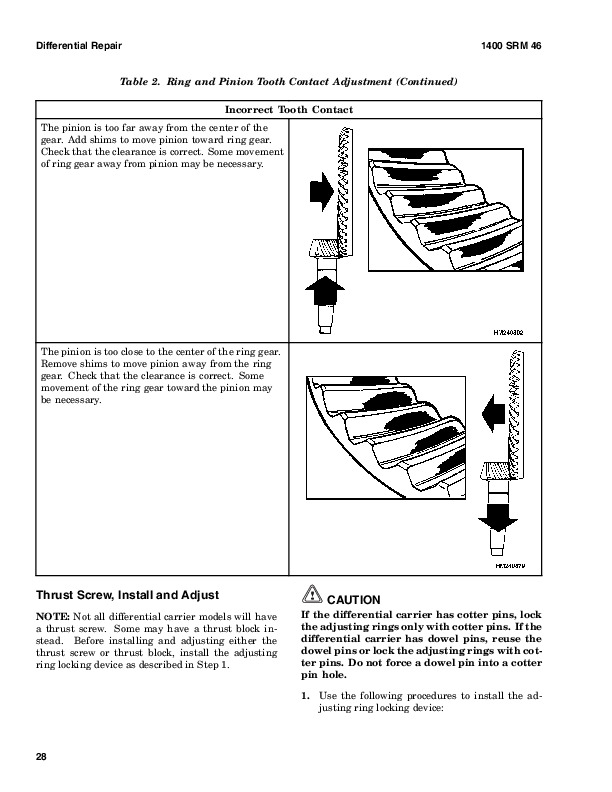
Table 2. Ring and Pinion Tooth Contact Adjustment…915
Table 3. General Specifications…919
Table 4. Rivet Installation Pressure…919
Table 5. Pinion Adjustment…919
Table 6. Pinion Preload Pressure…920
Table 7. Torque Specifications…921
Table 8. Torque Specifications for Metric Hardware…922
Remove…963
Disassemble…963
Clean…964
Assemble…964
Install…965
General Checks and Adjustments…965
Troubleshooting…968
hyster-910110-12-03-srm0143…973
toc…973
Instrument Panel Indicators and Senders…973
Safety Precautions Maintenance and Repair…974
General…977
Description…978
Steering Column Gauges, Meters, and Indicators…978
LED Display Panel…978
Battery Discharge Indicators…978
Brush Wear Indicators…985
Motor Temperature Indicators…985
LX Series Display Panel…987
Hourmeter Functions…987
Battery Indicator Function…988
Status Code Function…989
ZX Series Display Panels…989
Display Panel…989
Basic Display Panels…989
Performance Display…992
Brush Wear Indicators…995
Adjustments – General…996
Replacement – General Information…996
Meter Replacement…997
Sender Replacement…998
Fuel Level Sender…998
Pressure and Temperature Sender…998
ITW Display Panel Replacement…999
Remove…999
Column Mount Display Panel (EV-100/200ZX Motor Controllers) Repl…1000
Remove…1000
Display Panel Assembly, Replace…1000
Indicator LEDs…1001
Battery Indicators…1001
Digital Display (Performance Display Panel Only)…1001
Status Code or Performance Level Switches and Indicator LEDs (Pe…1001
Basic Display Panel, Replace Parts…1001
Performance Display Panel, Replace Parts…1003
Dash Mount Display Panel (EV100/200ZX Motor Controllers) Replace…1004
Remove and Replace…1004
Specifications…1004
Meter Specifications…1004
Sender Specifications…1005
Troubleshooting…1005
Meter…1005
hyster-910442-03-03-srm0231…1009
toc…1009
Metric and Inch (SAE) Fasteners…1009
Safety Precautions Maintenance and Repair…1010
General…1013
Threaded Fasteners…1013
Nomenclature, Threads…1013
Strength Identification…1014
Cotter (Split) Pins…1014
Fastener Torque Tables…1019
Conversion Table…1021
tables…1009
Table 1. Bolts and Screws…1015
Table 2. Studs and Nuts…1016
Table 3. Torque Nuts…1017
Table 4. Torque Nuts With Nylon Insert…1018
Table 5. Torque Values for Metric Fasteners*…1019
Table 6. Torque Values for Inch Fasteners*…1020
Table 7. Conversion Table for Metric and English units…1021
Table 8. Cotter Pin Dimensional Data…1022
Hyster H165-280XL (D007 / E007) & H300-360XL (C019 / D019) Repair Service Manual