Complete service repair manual for Hyster H45-50-55-60-65XM (D177) Forklifts Trucks, with all the shop information to maintain, diagnose, repair, and rebuild like professional mechanics.
Hyster H45XM, H50XM, H55XM, H60XM, H65XM (D177) workshop service & repair manual includes:
* Numbered table of contents easy to use so that you can find the information you need fast.
* Detailed sub-steps expand on repair procedure information
* Numbered instructions guide you through every repair procedure step by step.
* Troubleshooting and electrical service procedures are combined with detailed wiring diagrams for ease of use.
* Notes, cautions and warnings throughout each chapter pinpoint critical information.
* Bold figure number help you quickly match illustrations with instructions.
* Detailed illustrations, drawings and photos guide you through every procedure.
* Enlarged inset helps you identify and examine parts in detail.
897469 – Hyster H45-50-55-60-65XM (D177) Service Manual.pdf
Total Pages: 1,143 pages
File Format: PDF (Internal Links, Bookmarked, Table of Contents, Searchable, Printable, high quality)
Language: English
| Section |
Part No.
|
SRM Number
|
Rev Date |
| FRAME |
897486
|
0100 SRM 0505
|
01/01
|
| GM 3.0L ENGINE |
899766
|
0600 SRM 0003
|
08/03
|
| ISUZU 4JB1 (2.8L) ENGINE |
897418
|
0600 SRM 0467
|
04/93
|
| MAZDA M4-2.0G ENGINE |
897417
|
0600 SRM 0496
|
02/01
|
| GM 2.2L ENGINE |
897478
|
0600 SRM 0497
|
04/93
|
| ISUZU 4JG2 (3.1L) ENGINE |
897611
|
0600 SRM 0553
|
11/95
|
| COOLING SYSTEM |
897934
|
0700 SRM 0626
|
11/01
|
| LPG FUEL SYSTEM (GM 2.2L AND 3.0L) |
897479
|
0900 SRM 0498
|
01/96
|
| GASOLINE FUEL SYSTEM (MAZDA) |
897483
|
0900 SRM 0502
|
01/01
|
| LPG FUEL SYSTEM (MAZDA) |
897508
|
0900 SRM 0523
|
01/96
|
| SINGLE-SPD POWERSHIFT TRANS-DESCR & OPER |
897481
|
1300 SRM 0500
|
08/03
|
| SINGLE-SPD POWERSHIFT TRANSMISSION-REPAIR |
897482
|
1300 SRM 0501
|
08/03
|
| DRIVE AXLE |
897480
|
1400 SRM 0499
|
01/96
|
| STEERING AXLE |
897097
|
1600 SRM 0316
|
03/03
|
| STEERING HOUSING AND CONTROL UNIT |
897493
|
1600 SRM 0512
|
08/03
|
| BRAKE SYSTEM |
897487
|
1800 SRM 0506
|
01/96
|
| HYDRAULIC SYSTEM and GEAR PUMP |
897494
|
1900 SRM 0513
|
12/95
|
| MAIN CONTROL VALVE |
897497
|
2000 SRM 0516
|
11/95
|
| TILT CYLINDERS |
910102
|
2100 SRM 0103
|
10/03
|
| ALTERNATOR |
899784
|
2200 SRM 0002
|
09/02
|
| STARTER |
910107
|
2200 SRM 0106
|
02/01
|
| ELECTRONIC ENGINE CONTROL-REPAIR (GM 2.2L) |
897460
|
2200 SRM 0490
|
04/93
|
| INSTRUMENT CLUSTER |
897495
|
2200 SRM 0514
|
01/04
|
| MICROPROCESSOR SPARK TIMING SYSTEM (GM 2.2L) |
897496
|
2200 SRM 0515
|
04/93
|
| ELECTRICAL SYSTEM (ISUZU) |
897505
|
2200 SRM 0520
|
05/94
|
| ELECTRICAL SYSTEM (MAZDA) |
897509
|
2200 SRM 0524
|
02/01
|
| ELECTRONIC ENGINE CONTROL-DESCR/OPER (GM 2.2L) |
897516
|
2200 SRM 0525
|
04/93
|
| MSTS-GM 3.0L (EARLY CONTROL MODULES) |
897844
|
2200 SRM 0603
|
01/96
|
| ELECTRONIC ENGINE CONTROL-REPAIR (GM 3.0L) |
897855
|
2200 SRM 0611
|
02/96
|
| ELECTRONIC ENGINE CONTROL-DESCR/OPER (GM 3.0L) |
897856
|
2200 SRM 0612
|
01/96
|
| MSTS-GM 3.0L (LATER CONTROL MODULES) |
1473385
|
2200 SRM 0765
|
11/01
|
| MAST-DESCRIPTION |
897506
|
4000 SRM 0521
|
11/03
|
| MAST-REPAIR |
897507
|
4000 SRM 0522
|
11/03
|
| PERIODIC MAINTENANCE |
897470
|
8000 SRM 0493
|
07/97
|
| CAPACITIES AND SPECIFICATIONS |
897484
|
8000 SRM 0503
|
08/95
|
| DIAGRAMS |
897485
|
8000 SRM 0504
|
04/00
|
| PART NO. 897469 | |||
| Rev. 01/04 | |||
Steering Axle…..51
Safety Precautions Maintenance and Repair…..52
General…..55
Description…..55
Steering Axle Assembly Repair…..56
Remove…..56
Install…..56
Wheels and Hubs Repair…..57
Remove and Disassemble…..57
Clean…..57
Assemble and Install…..57
Spindles, Bearings, and Tie Rods Repair…..59
Remove…..59
Install…..59
Steering Cylinder Repair…..60
Remove and Disassemble…..60
Clean and Inspect…..61
Assemble and Install…..61
Torque Specifications…..61
Troubleshooting…..62
Mazda Engine…..271
Safety Precautions Maintenance and Repair…..272
General…..275
Description…..275
Engine Removal and Installation…..275
Cylinder Head, Camshaft, and Valve Mechanism Repair…..276
Remove…..276
Clean…..277
Inspect and Repair…..278
Cylinder Head…..278
Rocker Shaft Assembly…..278
Camshaft…..278
Valve Guides…..279
Valve Seats…..280
Valves…..280
Valve Springs…..281
Install…..281
Crankshaft and Main Bearings Repair…..284
Remove…..284
Inspect and Repair…..284
Crankshaft…..284
Main Bearings…..284
Install…..285
Pistons and Connecting Rods Repair…..286
Remove and Disassemble…..286
Clean…..286
Inspect and Repair…..286
Pistons…..286
Piston Rings…..286
Connecting Rods and Bearings…..287
Assemble and Install…..287
Cylinder Block Repair…..289
Oil Pump Repair…..289
Remove…..289
Disassemble…..290
Clean…..290
Inspect…..291
Assemble…..291
Install…..292
Cooling System Repair…..292
Thermostat…..292
Replace…..292
Fan Assembly…..292
Remove and Disassemble…..292
Assemble and Install…..293
Water Pump…..293
Remove and Disassemble…..293
Assemble and Install…..294
Distributor Repair…..295
Remove…..295
Install…..295
Flywheel and Ring Gear Repair S/H2.00-3.20XM (S/H40-65XM)…..296
Remove…..296
Ring Gear, Replace…..296
Install…..296
Flywheel Repair H1.50-175XM, H2.00XMS (S/H25-35XM, S/H40XMS)…..297
Remove…..297
Install…..297
Valve Adjustment…..298
Compression Pressure Check…..299
Engine Timing Adjustment…..299
Throttle Linkage Adjustment…..300
Gasoline Engines…..300
LPG Engines (IMPCO)…..300
LPG Engines (AISAN)…..300
Engine Specifications…..300
Engine Data…..300
Thermostat…..300
Cylinder Head…..300
Valve Mechanism…..301
Camshaft…..301
Crankshaft…..301
Connecting Rods…..302
Cylinder Block…..302
Pistons…..302
Oil Pump…..302
Torque Specifications…..303
Troubleshooting…..304
Single-Speed Powershift Transmission…..377
Safety Precautions Maintenance and Repair…..378
General…..381
Description and Operation…..381
General…..381
Torque Converter…..382
Description…..382
Operation…..382
Clutch Assemblies…..384
Description…..384
Operation…..385
Hydraulic System…..388
General…..388
Control Valve…..389
General…..389
Clutch Pressure Regulator…..390
Inching Spool Assembly…..391
Direction Spool…..391
Modulator Circuit…..391
Torque Converter Regulator…..391
MONOTROL® Pedal…..391
MONOTROL Pedal Start Circuit…..392
Direction Control Lever…..392
Differential…..392
Oil Flow Diagrams…..394
Neutral…..394
Modulator Operation…..394
Forward…..398
Forward-Inching…..398
hyster-897482-08-03-srm0501…..405
toc…..405
Single-Speed Powershift Transmission…..405
Safety Precautions Maintenance and Repair…..406
General…..409
Transmission Removal…..411
Torque Converter and Housing Repair…..413
Remove…..413
Install…..413
Transmission Pump Repair…..415
Remove…..415
Repair…..415
Install…..415
Front Cover and Pump Drive Repair…..415
Remove and Disassemble…..415
Assemble and Install…..415
Clutch Assemblies Repair…..418
Remove and Disassemble…..421
Inspect…..422
Assemble…..423
Install…..428
Differential Repair…..429
Remove and Disassemble…..429
Inspect…..430
Assemble and Install…..431
Control Valve Repair…..438
Remove and Disassemble…..438
Inspect…..441
Assemble and Install…..441
MONOTROL® Pedal Repair…..442
Remove and Disassemble…..442
Assemble and Install…..442
Direction Control Lever Repair…..446
Remove and Disassemble…..446
Assemble and Install…..446
Stall Test…..447
Inching/Brake Pedal Adjustment…..448
Neutral Start Switch, MONOTROL Pedal Adjustment H2.00-3.20XM (H4…..452
Neutral Start Switch, MONOTROL Pedal Adjustment S2.00-3.20XM (S4…..453
Neutral Start Switch Test, MONOTROL® Pedal…..454
Oil Pressure Checks…..454
Relief Valve for Transmission Pump Check, TEST PORT 1…..454
Clutch Pressure Check, TEST PORTS 2 and 3…..454
Torque Converter Regulator Check, TEST PORT 4…..455
Lubrication Circuit Oil Pressure Check, TEST PORT 5…..455
Modulator Pressure Check, TEST PORT 6…..456
Troubleshooting…..456
Troubleshooting – Pressure Tests…..459
tables…..405
Table 1. Adjustment of Shims for Pinion Assembly…..432
Table 2. Ring and Pinion Tooth Contact Adjustment…..433
Table 3. Stall Speeds…..448
Table 4. Transmission Oil Pressures Test Ports…..455
Safety Precautions Maintenance and Repair…..536
General…..539
Description…..539
Operation…..540
Steering Wheel and Column Assembly Repair…..541
Steering Column Assembly, Remove…..541
Steering Control Unit…..546
Disassemble…..546
Clean…..549
Assemble…..550
Install…..557
Steering Column Assembly, Install…..559
System Air Removal…..560
Remove…..560
Troubleshooting…..560
Standard Display Panel…..586
Enhanced Display Panel…..587
Curtis 1215 Display Panel…..591
Description and Features…..591
Operation…..591
Cluster-Type Display Panel (Internal Combustion) Replacement…..592
Remove and Disassemble…..592
Assemble and Install…..595
Cluster Display Panel (Electric Lift Truck) Replacement…..597
Display Panel Assembly, Replace…..597
LED Indicators…..597
Battery Indicators…..598
Digital Display (Enhanced Display Panel Only)…..598
Status Code or Performance Level Switches and LED indicators (En…..598
Standard Display Panel Parts, Replace…..598
Enhanced Display Panel Parts, Replace…..599
Curtis 1215 Display Panel Replacement…..599
Remove…..599
Install…..599
tables…..577
Table 1. Instrument Cluster, Internal Combustion…..581
Mast Mounts…..677
Two-Stage Mast, Limited Free-Lift (LFL)…..678
Description and Operation…..678
Two-Stage Mast, Full Free-Lift (FFL)…..680
Description and Operation…..680
Three-Stage Mast, Full Free-Lift (FFL)…..682
Description and Operation…..682
Cylinder Cushion During Lifting Sequence…..685
Cylinder Cushion During Lowering Sequence…..686
hyster-897507-11-03-srm0522…..689
toc…..689
Mast…..689
Safety Precautions Maintenance and Repair…..690
General…..693
Safety Procedures When Working Near Mast…..693
Forks Repair…..695
Remove…..695
Install…..695
Carriages Repair…..696
Standard Carriage, Remove…..696
Hang-On Sideshift Carriage, Remove…..697
Standard Carriage and Hang-On Sideshift Carriage, Repair…..698
Standard Carriage, Install…..698
Hang-On Sideshift Carriage, Install…..699
Integral Sideshift Carriage…..699
Remove…..699
Clean and Inspect…..701
Repair…..701
Install…..702
Mast Repair…..702
Remove…..702
Two-Stage LFL and Two-Stage FFL Masts, Disassemble…..704
Three-Stage FFL Mast…..711
Disassemble…..711
Mast and Chains, Clean and Inspect…..715
Two-Stage LFL and Two-Stage FFL Mast, Assemble…..716
Three-Stage FFL Mast, Assemble…..717
Install…..718
Lift Cylinders Repair…..719
Main Lift Cylinders, Remove…..719
Free-Lift Cylinder, Remove…..720
Lift Cylinders, Disassemble…..720
Lift Cylinders, Assemble…..723
Main Lift Cylinders, Install…..724
Free-Lift Cylinder, Install…..724
Header Hose Arrangements…..725
Two-Stage LFL Mast, New Hose Install…..725
Two-Stage LFL Mast, Adjust Hoses After Installation…..730
Two-Stage FFL Mast, New Hose Install…..731
Two-Stage FFL Mast, Adjust Hoses After Installation…..737
Three-Stage FFL Mast, New Hose Install…..737
Three-Stage FFL Mast, Adjust Hoses After Installation…..748
Header Hose Arrangement…..749
Two-Stage LFL Mast, New Hose Install…..749
Two-Stage LFL Mast, Adjust Hoses After Installation…..753
Two-Stage FFL Mast, New Hose Install…..753
Two-Stage FFL Mast, Adjust Hoses After Installation…..758
Three-Stage FFL Mast, New Hose Install…..760
Three-Stage FFL Mast, Adjust Hoses After Install…..768
Lift and Tilt System Leak Check…..769
Lift Cylinders Leak Check…..769
Tilt Cylinders Leak Check…..769
Tilt Cylinders Adjustment…..770
Lift Chains Adjustment…..771
Mast Adjustment…..773
Carriage Adjustment…..775
Troubleshooting…..775
tables…..689
Table 1. Hook-Type Carriage Chain Adjustment…..772
Table 2. Pin-Type Carriage Chain Adjustment…..772
toc…..807
Electrical System…..807
Safety Precautions Maintenance and Repair…..808
General…..811
Description…..811
Starting System…..811
Ignition System…..811
Charging System…..812
Starter Repair…..813
Remove and Disassemble…..813
Assemble and Install…..813
Coil Replacement…..815
Distributor Repair H1.50-1.75XM, H2.00XMS (S/H25-35XM, S/H40XMS)…..816
Remove and Disassemble…..816
Assemble and Install…..816
Distributor Repair S/H2.00-3.20XM (S/H40-65XM)…..818
Remove and Disassemble…..818
Assemble and Install…..820
Alternator Repair…..820
Remove and Disassemble…..820
Assemble and Install…..822
General Checks and Adjustments…..822
Starter Checks…..822
Operation, Check…..822
Brush Holder, Check…..823
Armature, Check…..823
Field Windings, Check…..823
Clutch and Bearing, Check…..824
Ignition System Check and Adjustment…..824
Engine Timing, Adjust…..824
Spark Plugs, Check…..825
Charging Circuit Checks…..825
Low Output, Check…..825
High Output, Check…..826
Diodes, Check…..826
Rotor Field Winding, Check…..827
Stator Windings, Check…..827
Brushes and Bearings, Check…..828
Voltage Regulator, Check…..828
Troubleshooting…..828
General…..1057
Description…..1058
Radiator…..1058
Radiator Cap…..1058
Thermostat…..1058
Water Pump…..1059
Fan and Fan Shroud…..1059
Cooling System Checks…..1059
Radiator…..1059
Thermostat…..1059
Water Pump…..1060
Exhaust Leaks…..1060
Fan and Fan Shroud…..1060
Radiator Cleaning…..1060
Drain…..1060
Clean…..1060
Fill…..1061
Troubleshooting…..1062
hyster-899766-08-03-srm0003…..1065
toc…..1065
GM Engines…..1065
Safety Precautions Maintenance and Repair…..1066
General…..1069
Description…..1069
Engine Removal and Installation…..1071
Cylinder Head and Valve Mechanism Repair…..1071
Cylinder Head, Remove…..1071
Cylinder Head, Disassemble…..1071
Clean and Inspect…..1071
Valves and Valve Seats…..1074
Studs for Rocker Arms…..1074
Hydraulic Valve Lifters, Replace…..1075
Hydraulic Valve Lifters, Clean and Inspect…..1075
Cylinder Head, Assemble…..1075
Cylinder Head, Install…..1075
Valve Clearance, Adjust…..1076
Rocker Arm Cover, Install…..1077
Timing Gear Cover Repair…..1077
Remove…..1077
Install…..1078
Camshaft Repair…..1079
Remove…..1079
Inspect…..1079
Camshaft Bearing…..1080
Remove…..1080
Install…..1080
Distributor Repair…..1081
Remove…..1081
Install…..1081
Lubrication System Repair…..1082
Oil Sump…..1082
Remove…..1082
Install…..1082
Oil Pump…..1082
Remove…..1082
Disassemble and Repair…..1082
Assemble…..1083
Install…..1083
Piston and Connecting Rod Assemblies Repair…..1083
Connecting Rod Bearings, Replace…..1083
Piston and Connecting Rod Assemblies, Remove…..1084
Piston and Connecting Rod Assemblies, Disassemble…..1085
Piston, Clean and Inspect…..1085
Cylinder Bores, Inspect and Repair…..1085
Piston Rings, Inspect…..1086
Piston and Connecting Rod Assemblies, Assemble…..1086
Piston and Connecting Rod Assemblies, Install…..1088
Crankshaft Repair…..1088
Main Bearings, Replace…..1088
Oil Seal for Rear Main Bearing, Replace (GM 4-181 and 3.0L Only)…..1089
Oil Seal for Rear Main Bearing, Replace (Engines That Have Two-P…..1089
Remove…..1091
Inspect and Repair…..1091
Main Bearing and Journal Clearance, Check…..1092
Install…..1092
Flywheel and Flywheel Housing Repair…..1093
Remove…..1094
Ring Gear, Replace…..1095
Install…..1095
Cooling System Repair…..1095
Coolant Pump…..1095
Fan Drive…..1095
Viscous Fan Drive…..1095
Engine Specifications…..1097
Engine Data…..1097
Cylinder Head…..1098
Hydraulic Valve Lifter…..1098
Camshaft…..1099
Pistons…..1100
Cylinder Bore…..1100
Crankshaft…..1101
Connecting Rods…..1101
Cooling System…..1102
Lubrication System…..1102
Torque Specifications…..1102
Troubleshooting…..1103
hyster-910102-10-03-srm0103…..1109
toc…..1109
Tilt Cylinders…..1109
Safety Precautions Maintenance and Repair…..1110
General…..1113
Description…..1113
Tilt Cylinder Repair…..1113
Remove…..1113
Disassemble…..1113
Clean…..1113
Assemble…..1114
Tilt Cylinders With O-Ring or Single-Lip Seals…..1114
Tilt Cylinders for XM and XMS Models…..1115
Tilt Cylinders for H700-800A and Early Model H700-920B…..1116
Install…..1117
Tilt Cylinders Using Chevron Packing…..1118
Install…..1119
Tilt Cylinder Leak Check…..1121
Tilt Cylinder Stroke and Mast Tilt Angle Adjustment…..1122
Torque Specifications…..1123
Piston Rod Nut…..1123
Retainer…..1124
Troubleshooting…..1126
tables…..1109
Table 1. Movement Rates (Maximum) for Tilt Cylinders…..1122
Starter…..1129
Safety Precautions Maintenance and Repair…..1130
General…..1133
Description and Operation…..1133
Starter Repair…..1135
Remove…..1135
Disassemble…..1135
Clean…..1136
Assemble…..1136
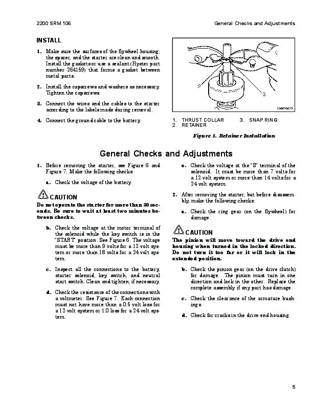
Install…..1137
General Checks and Adjustments…..1137
Troubleshooting…..1140
Hyster H45-50-55-60-65XM (D177) Repair Service Manual