Complete service repair manual for Hyster Lift Trucks S70XM-S120XM (F004), with all the shop information to maintain, diagnose, repair, and rebuild like professional mechanics.
Hyster Service Manual S70-120XM (F004) workshop service & repair manual includes:
* Numbered table of contents easy to use so that you can find the information you need fast.
* Detailed sub-steps expand on repair procedure information
* Numbered instructions guide you through every repair procedure step by step.
* Troubleshooting and electrical service procedures are combined with detailed wiring diagrams for ease of use.
* Notes, cautions and warnings throughout each chapter pinpoint critical information.
* Bold figure number help you quickly match illustrations with instructions.
* Detailed illustrations, drawings and photos guide you through every procedure.
* Enlarged inset helps you identify and examine parts in detail.
1559863 – Hyster Service Manual S70-120XM (F004).pdf
Total Pages: 1,085 pages
File Format: PDF (Internal Links, Bookmarked, Table of Contents, Searchable, Printable, high quality)
Language: English
| Section | Part No. | SRM Number | Rev Date |
| FRAME | 1510458 | 0100 SRM 0981 | 12/03 |
| GM V6-4.3L ENGINE WITH FUEL INJECTION | 897800 | 0600 SRM 0590 | 11/03 |
| PERKINS DIESEL ENGINE-1000 SERIES (AR, YG, YH) | 1455747 | 0600 SRM 0705 | 09/03 |
| COOLING SYSTEM | 897934 | 0700 SRM 0626 | 11/01 |
| ELECTRONIC CONTROLLED LPG/GASOLINE FUEL SYSTEM GM 3.0L & 4.3L EPA COMPLIANT ENGINES |
1559540 | 0900 SRM 1088 | 03/04 |
| SINGLE-SPEED PS TRANSMISSION-REPAIR | 897308 | 1300 SRM 0397 | 02/04 |
| SINGLE-SPEED PS TRANS-DESCR / OPER | 897322 | 1300 SRM 0399 | 09/03 |
| DRIVE AXLE | 1510463 | 1400 SRM 0984 | 09/03 |
| STEERING CONTROL UNIT | 1466241 | 1600 SRM 0732 | 10/03 |
| STEERING AXLE | 897108 | 1600 SRM 0326 | 10/03 |
| BRAKE SYSTEM | 1510466 | 1800 SRM 0985 | 09/03 |
| HYDRAULIC GEAR PUMP | 910091 | 1900 SRM 0097 | 10/03 |
| HYDRAULIC PUMP DRIVE ASSEMBLY | 897121 | 1900 SRM 0339 | 10/03 |
| HYDRAULIC SYSTEM | 1466217 | 1900 SRM 0743 | 10/03 |
| MAIN CONTROL VALVE | 1466211 | 2000 SRM 0754 | 12/03 |
| TILT CYLINDERS | 1510469 | 2100 SRM 0986 | 09/03 |
| STARTER | 1466193 | 2200 SRM 0755 | 10/03 |
| INSTRUMENT PANEL INDICATORS and SENDERS | 1468474 | 2200 SRM 0756 | 11/03 |
| ALTERNATOR | 899784 | 2200 SRM 0002 | 10/03 |
| ELECTRONIC CONTROL MODULE (ECM) DIAGNOSTIC TROUBLESHOOTING GM 3.0L AND 4.3L EP COMPLIANT ENGINES |
1559545 | 2200 SRM 1090 | 01/04 |
| HIGH VOLTAGE SWITCH (HVS) IGNITION GM 4.3L EPA COMPLIANT ENGINES |
1559550 | 2200 SRM 1097 | 12/03 |
| LIFT CYLINDERS | 1466169 | 4000 SRM 0741 | 10/03 |
| MAST | 1466163 | 4000 SRM 0736 | 10/03 |
| INCH (SAE) and METRIC FASTENERS | 910442 | 8000 SRM 0231 | 03/03 |
| PERIODIC MAINTENANCE | 1510475 | 8000 SRM 0987 | 12/03 |
| CAPACITIES and SPECIFICATIONS | 1510478 | 8000 SRM 0988 | 09/03 |
| DIAGRAMS | 1510481 | 8000 SRM 0989 | 12/03 |
| PART NO. 1559863 | |||
| Rev. 03/04 | |||
Perkins Diesel Engines…2
Safety Precautions Maintenance and Repair…3
General…10
General Safety Rules…10
Description…11
Engine Serial Number Codes…14
Engine Data…14
Engine Removal and Installation…16
Lift Engine…16
Cylinder Head Assembly Repair…16
Valve Cover…16
Remove…16
Install…17
Rocker Arm Assembly…17
Remove…17
Install…17
Disassemble…17
Inspect…17
Assemble…18
Valve Clearance Adjustments…18
Four-Cylinder Engines…19
Six-Cylinder Engines…19
Valve Springs…19
Cylinder Head Assembly…21
Remove…21
Install…23
Valves and Valve Springs…27
Remove…27
Inspect…27
Install…28
Valve Guides…28
Inspect…28
Remove…29
Install…29
Cylinder Head and Valve Seats…29
Inspect…29
Repair…29
New Valve Seats, Install…29
Piston and Connecting Rod Assemblies Repair…31
Rod Bearings…31
Remove…32
Install…32
Piston and Connecting Rod Assembly…33
Service Note…33
Remove…33
Install…34
Piston Rings…35
Remove…35
Inspect…35
Install…35
Piston and Connecting Rod…36
Disassemble…36
Inspect…37
How to Select Correct Replacements…37
Install…38
Piston Cooling Jets…38
Remove…38
Install…39
Crankshaft Assembly Repair…39
General…39
Crankshaft Pulley…40
Engine AR, Remove…40
Engines YG and YH, Remove…40
Inspect…41
Engine AR, Install…41
Engines YG and YH, Install…41
Rear Oil Seal…42
Replace…42
Main Bearings…43
Remove…43
Inspect…44
Install…44
Thrust Washers…44
Crankshaft Axial Movement, Check…44
Remove…45
Install…45
Crankshaft…46
Remove…46
Inspect…46
Install…46
Flywheel…48
Remove…48
Ring Gear, Replace…48
Install…48
Flywheel Housing…49
Remove…49
Install…49
Timing Case and Timing Gears Repair…50
General…50
Timing Case Cover…50
Remove…50
Install…51
Front Oil Seal…51
Remove…51
Install…51
Crankshaft Pulley Wear Sleeve…52
Install…52
Idler Gear and Hub…52
Remove…52
Install…53
Air Compressor Drive, Bendix…54
Disassemble…54
Assemble…55
Fuel Injection Pump Gear…55
Remove…56
Install…56
Camshaft Gear…57
Remove…57
Install…57
Crankshaft Gear…58
Remove…58
Install…58
Timing Case…58
Remove…58
Install…59
Camshaft and Tappets…60
Remove…60
Install…60
Cylinder Block Assembly Repair…61
Description…61
Cylinder Block…61
Disassemble…61
Inspect…62
Assemble…62
Cylinder Bore (Four-Cylinder Engines)…63
Cylinder Liner (Six-Cylinder Engines)…63
Inspect…63
Cylinder Liner Condition, Check…63
Remove…64
Service Liner, Install…65
Partially Finished Liner, Install…66
Engine Timing…67
Description…67
How to Set Number One Piston to TDC on Compression Stroke…68
How to Set Number One Piston to TDC on Compression Stroke (Alter…69
Valve Timing, Check…69
Fuel Injection Pump Timing, Check…70
Turbocharger – Engine YH Repair…71
General…71
Remove…71
Install…71
Impeller and Compressor Housing, Clean…72
Lubrication System Repair…73
General…73
Oil Filter, Replace…73
Filter Head…74
Remove and Install…74
Oil Sump…74
Remove…74
Install…75
Oil Pump…75
Remove…75
Inspect…75
Install…76
Relief Valve…76
Remove…76
Disassemble…77
Inspect…77
Assemble…77
Install…77
Idler Gear Shaft, Replace…78
Remove…78
Remove (Alternative)…78
Install…79
Install (Alternative)…79
Install (Alternative for Four-Cylinder Engines Only)…80
Fuel System Repair…80
Description…80
Fuel Injection Pump…81
Remove…81
Install…82
Check and Adjust…83
Fuel System, Remove Air…83
Fuel Filter, Replace…84
Canister Type…85
Quick Release Canister Type…85
Fuel Injectors…86
Remove…86
Inspect…87
Install…87
Fuel Pump…88
Remove…88
Disassemble…88
Assemble…88
Install…89
Test…89
Cooling System Repair…90
General…90
Thermostat…90
Remove…90
Install…90
Test…91
Coolant Pump…91
Remove…91
Disassemble…91
Assemble…93
Install…95
Fan and Fan Drive…96
Remove…96
Install…96
Oil Cooler (Six-Cylinder Engines)…97
Remove…97
Disassemble and Assemble…97
Install…97
Oil Cooler By-Pass Valve…97
Electrical Equipment Repair…98
Drive Belts…98
Alternator…99
Remove…99
Install…99
Starter Motor…99
Remove…99
Install…99
Cold Start Aid…99
Air Compressor – Engines YG and YH…99
General…99
Repair…100
Remove…100
Install…100
Rotary Exhauster Replacement…101
Remove…101
Clean…101
Install…101
Engine Specifications…102
Cylinder Head Assembly…102
Piston and Connecting Rods…105
Crankshaft Assembly…108
Crankshaft Overhaul…109
Timing Case and Drive Assembly…111
Engine Block Assembly…112
Turbocharger…115
Lubrication System…115
Fuel System…117
Cooling System…119
Flywheel and Housing…119
Electrical Equipment…120
Torque Specifications…121
Cylinder Head Assembly…121
Piston and Connecting Rod Assemblies…121
Crankshaft Assembly…121
Timing Case and Drive Assembly…121
Turbocharger…121
Lubrication System…121
Fuel System…121
Cooling System…122
Flywheel…122
Auxiliary Equipment…122
Special Torque Specifications…123
Flywheel and Housing…123
Turbocharger…123
Electrical Equipment…123
Auxiliary Equipment…123
Special Tools…124
Troubleshooting…128
tables…2
Table 1. Cylinder Head…102
Table 2. Valve Guides…102
Table 3. Inlet Valves…103
Table 4. Exhaust Valves…104
Table 5. Valve Springs…105
Table 6. Tappets…105
Table 7. Rocker Arm Shaft…105
Table 8. Rocker Arms and Bushings…105
Table 9. Pistons (Engine AR)…105
Table 10. Pistons (Engines YG and YH)…106
Table 11. Piston Rings (Engine AR)…106
Table 12. Piston Rings (Engines YG and YH)…107
Table 13. Piston Pins…107
Table 14. Connecting Rods…107
Table 15. Small End Bushings…107
Table 16. Connecting Rod Bearings (Engines AR and YG)…108
Table 17. Connecting Rod Bearings (Engine YH)…108
Table 18. Piston Cooling Jets…108
Table 19. Crankshaft…108
Table 20. Main Bearings…109
Table 21. Crankshaft Thrust Washers…109
Table 22. Crankshaft Heat Treatment…109
Table 23. Crankshaft Overhaul Specifications…110
Table 24. Maximum Variation (Run-out)…111
Table 25. Camshaft…111
Table 26. Camshaft Thrust Washer…111
Table 27. Camshaft Gear…112
Table 28. Gear for Fuel Injection Pump…112
Table 29. Crankshaft Gear…112
Table 30. Idler Gear and Hub…112
Table 31. Cylinder Block (Engine AR)…113
Table 32. Cylinder Bore Specifications…113
Table 33. Cylinder Block (Engines YG and YH)…114
Table 34. Cylinder Liners (Engines YG and YH)…114
Table 35. Cylinder Liner Specifications (Partially Finished)…115
Table 36. Oil Pump (Engine AR)…115
Table 37. Oil Pump (Engines YG and YH)…116
Table 38. Idler Gear for Oil Pump…116
Table 39. Relief Valve…116
Table 40. Oil Filter…116
Table 41. Lucas Fuel Injection Pump…117
Table 42. Fuel Pump (Engine AR)…117
Table 43. Fuel Pump (Engines YG and YH)…117
Table 44. Fuel Filter…117
Table 45. Fuel Injector Codes…118
Table 46. Coolant Pump…119
Table 47. Thermostat…119
Table 48. Fan Drive Housing…119
Table 49. Limits for Flywheel Run Out and Alignment (Total Indic…119
Table 50. Alternator…120
Table 51. Starter Motor…120
Table 52. Cold Start Aid…120
Table 53. List of Possible Causes…129
hyster-1466163-10-03-srm0736…134
toc…134
Masts…134
Safety Precautions Maintenance and Repair…135
General…138
Description and Operation…138
Carriages…138
Two-Stage Mast With Limited Free-Lift…138
Two-Stage Mast With Full Free-Lift…139
Three-Stage Mast With Full Free-Lift…140
Safety Procedures When Working Near Mast…142
Fork Replacement…144
Remove…145
Install…145
Carriage Repair…146
Remove…146
Sideshift Carriage Repair…147
Remove…147
Disassemble…147
Assemble…147
Install…148
Two-Stage Mast With Limited Free-Lift Repair…149
Remove – H3.50-5.50XM (H70-120XM) Model Lift Trucks…149
Remove – S3.50-5.50XM (S70-120XM) and E3.50-5.50XL 3 (E70-120XL …149
Disassemble…149
Clean and Inspect…153
Assemble…154
Install – H3.50-5.50XM (H70-120XM) Lift Truck Models…155
Install – S3.50-5.50XM (S70-120XM) and E3.50-5.50XL 3 (E70-120XL…157
Two-Stage Mast With Full Free-Lift Repair…159
Remove…159
Disassemble…159
Clean and Inspect…161
Assemble…161
Install…161
Three-Stage Mast With Full Free-Lift Repair…163
Remove…163
Disassemble…163
Clean and Inspect…166
Assemble…166
Install…168
Mast Operation Check…172
Lift and Tilt System Leak Check…172
Lift System…172
Tilt System…173
Tilt Cylinder Stroke and Backward Tilt Angle Adjustment…174
Lift Chain Adjustments…175
Mast Adjustments…178
Carriage Adjustment…180
Troubleshooting…180
tables…134
Table 1. Tilt Cylinder Leak Check Specifications, S3.50-5.50XM (…174
Table 2. Hook type Carriage Chain Adjustment…176
Table 3. Pin-Type Carriage Chain Adjustment…176
hyster-1466169-10-03-srm0741…186
toc…186
Lift Cylinders…186
Safety Precautions Maintenance and Repair…187
Safety Procedures When Working Near Mast…190
General…192
Description…192
Lowering Control Valve (Velocity Fuse)…192
Lift Cylinder Repair…195
Remove…195
Disassemble…196
Assemble…196
Install…197
Lift System Leak Check…197
Troubleshooting…198
hyster-1466193-10-03-srm0755…202
toc…202
Starter…202
Safety Precautions Maintenance and Repair…203
General…206
Description…206
Yoke Assembly…207
Armature Assembly…207
Clutch Assembly…207
Magnetic Switch Assembly…207
Operation…207
Starter Repair…208
Remove…208
Disassemble…209
Clean…213
Assemble…213
Install…216
General Checks and Adjustments…217
Armature Tests…218
Armature Short Circuit Test…218
Armature Winding Ground Test…218
Commutator Run-Out Test…218
Yoke Test…219
Brush and Brush Holder Check…219
Brush Holder Insulation Test…219
Clutch Test…219
Magnetic Switch Test…220
Pull-In Test…220
Hold-In Test…220
Return Test…220
Performance Tests…221
No-Load Test…221
Troubleshooting…221
hyster-1466211-12-03-srm0754…226
toc…226
Main Control Valve…226
Safety Precautions Maintenance and Repair…227
General…230
Description…230
Operation…230
Lift Section…230
Tilt and Auxiliary Sections…234
Reattaching the Clevis End of the Tilt Spool…235
Relief Valve…235
Main Control Valve Repair…235
Remove and Disassemble…235
Clean and Inspect…237
Assemble…239
Install…239
Pressure Relief Valve Check and Adjustment…240
Main Relief Valve (Lift)…240
Steering Relief Valve…240
Secondary Relief Valve (Tilt and Auxiliary)…243
Specifications…244
Troubleshooting…244
hyster-1466217-10-03-srm0743…250
toc…250
Hydraulic System…250
Safety Precautions Maintenance and Repair…251
General…254
Description…254
Operation…256
Hydraulic Pump H3.50-5.50XM (H70-120XM)…256
Hydraulic Pump S3.50-5.50XM (S70-120XM)…256
Main Control Valve…257
Steering Control Unit…257
Specifications…258
Hydraulic System Capacity…258
Hydraulic Tank Capacity…258
Relief Pressures @ 2200 rpm, 50 to 80 C ( 120 to 180 F)…258
Hydraulic Pump Flow to Valve…258
Steering Priority Flow…258
Troubleshooting…259
Lift, Lower and Tilt Circuit…259
Steering Circuit…260
hyster-1466241-10-03-srm0732…264
toc…264
Steering Control Unit…264
Safety Precautions Maintenance and Repair…265
General…268
Description…268
Operation…268
Steering Wheel and Column Assembly Repair…270
Remove and Disassemble…270
Assemble and Install…270
Steering Control Unit…273
Disassemble…273
Clean…275
Assemble…276
System Air Removal…279
Troubleshooting…279
hyster-1468474-11-03-srm0756…284
toc…284
Instrument Panel Indicators and Senders…284
Safety Precautions Maintenance and Repair…285
General…288
Description…288
Instruments and Senders…288
Password Function…295
Supervisor Password Function…295
Entering Operator Passwords…295
Deleting Operator Passwords…296
Retrieve the Most Recent Operator Password Used to Enable the Tr…296
Display All Operator Passwords Programmed Into the System…296
Enable and Disable Operator Passwords Function…296
Allow Supervisor Password to Enable the Truck to Start…296
Operator Passwords Function…296
Component Replacement – General Information…297
Sender Replacement…297
Fuel Level Sender…297
Pressure and Temperature Sender…298
Display Panel Replacement…299
Specifications…301
Troubleshooting…302
tables…284
Table 1. Instrument Panel Description…289
Table 2. Sender Description…294
Table 3. Meter and Sender Specifications…301
hyster-1510458-12-03-srm0981…306
toc…306
Frame…306
Safety Precautions Maintenance and Repair…307
Description…310
Counterweight Repair…311
Remove…312
Install…317
Exhaust System Repair…318
Muffler…318
Remove…318
Install…319
Exhaust Pipe – LPG/Gas Engine…319
Remove…319
Install…319
Exhaust Pipe – Diesel Engine…323
Remove…323
Install…323
Hood Repair…324
Remove…324
Install…324
Overhead Guard Repair…325
Remove…325
Install…325
Operator Restraint System Repair…325
Radiator and Coolant System…326
Remove…326
Install…326
Alternator Replacement…328
Remove…328
Install…328
Engine Removal and Installation…328
Remove…328
Install…332
Fuel and Hydraulic Tanks Repair…334
Inspect…334
Repairs, Small Leaks…334
Repairs, Large Leaks…334
Clean…334
Steam Method of Cleaning…334
Chemical Solution Method of Cleaning…335
Other Methods of Preparation for Repair…335
Safety Labels…336
tables…306
Table 1. Weight of Counterweights…316
hyster-1510463-09-03-srm0984…342
toc…342
Drive Axle…342
Safety Precautions Maintenance and Repair…343
General…346
Description…346
Drive Axle Repairs…346
Remove and Disassemble…346
Clean and Inspect…348
Brakes…348
Drive Axle…349
Assembly and Installation…349
Torque Specifications…351
Troubleshooting…352
hyster-1510466-09-03-srm0985…356
toc…356
Brake System…356
Safety Precautions Maintenance and Repair…357
General…360
Description and Operation…360
Brake Booster and Master Cylinder…360
Service Brake Assembly…360
Parking Brake…360
Brake Shoe Assemblies Repair…361
Remove and Disassemble…361
Clean…361
Inspect…363
Assemble and Install…364
Brake Booster and Master Cylinder…366
Remove…366
Disassemble…366
Clean and Inspect…366
Assemble…368
Install…368
Parking Brake Repair…370
Remove and Disassemble…370
Assemble and Install…370
Brake System Air Removal…370
Brake Pedal Adjustment…371
Parking Brake Adjustment…371
Parking Brake Not Applied Switch Test…372
Parking Brake Switch Test (MONOTROL® Pedal Only)…372
Brake Shoes Adjustment…372
Troubleshooting…373
hyster-1510469-09-03-srm0986…378
toc…378
Tilt Cylinders…378
Safety Precautions Maintenance and Repair…379
General…382
Description…382
Tilt Cylinder Repair…382
Remove…382
Disassemble…382
Clean…382
Inspect…382
Assemble…383
Install…384
Tilt Cylinder Leak Check…385
Tilt Cylinder Stroke and Mast Tilt Angle Adjustment…385
Tilt Cylinder Specifications…385
tables…378
Table 1. Leak Check Specifications…385
hyster-1510475-12-03-srm0987…388
toc…388
Periodic Maintenance…388
Safety Precautions Maintenance and Repair…389
General…394
Serial Number Data…394
How to Move Disabled Lift Truck…394
How to Tow Lift Truck…394
How to Put Lift Truck on Blocks…395
How to Raise Drive Tires…395
How to Raise Steering Tires…395
Maintenance Schedule…396
Maintenance Procedures Every 8 Hours or Daily…404
How to Make Checks With Engine Stopped…404
Engine Oil…405
Hydraulic System Oil…405
Cooling System Reservoir Level…406
Fuel System…406
Battery…407
Tires and Wheels…407
Forks…407
Adjust…407
Hook Fork, Remove…409
Hook Fork, Install…409
Forks, Mast, and Lift Chains, Inspect…410
Operator Restraint System…410
Safety Labels…411
Cooling System, Clean Debris from Radiator Core…412
How to Make Checks With Engine Running…412
Gauges, Lights, Horn, and Fuses…412
Engine Oil Pressure…413
Cooling System Temperature…413
Powershift Transmission Oil level Check…414
Control Levers and Pedals…414
Lift System Operation…414
Service Brakes…415
Parking Brakes…415
Steering System…415
Cooling System, Clean Debris from Radiator Core…415
Maintenance Procedures Every 250 Hours or 6 Weeks…416
Engine Oil and Filter, GM V-6 Engines…416
Sideshift Carriage Lubrication…417
Tilt Cylinder Lubrication…417
Air Filter, GM V-6 EPA Compliant Engine …418
Maintenance Procedures Every 500 Hours or 3 Months…419
Lift Chain Lubrication…419
Engine Oil and Filter, Perkins Diesel Engine…419
Drive Belts…419
Fan Drive Belts…420
Perkins Diesel Engine…420
Alternator Drive Belt…420
GM 4.3 L Engine…421
Serpentine Drive Belt…421
Tension Screw Adjustment…421
Hydraulic Tank Breather, Clean and Check…422
Brake Fluid…422
Lift Chains Wear Check…423
Forks, Wear and Damage Check…423
Mast Lubrication…423
Control Levers and Pedals Lubrication…423
Steering Axle Lubrication…424
Fuel System, Checks and Adjustments…424
LPG Carburetor…424
Fuel Injection (Perkins Engine)…424
GM V-6 Engine…424
Inching/Brake Pedal…424
Steering Tie Rods…424
Fork Pins and Guides…424
Wheel Nuts…424
Air Filter…425
Battery…425
Maintenance Procedures Every 1000 Hours or 6 Months…426
Fuel Filter, Replace (Diesel Engine)…426
Fuel System, Remove Air (Perkins 1004.42 Diesel Engine)…426
Water Separator, Diesel Engine…428
PCV Valve, GM V-6…428
Crankcase Breather, GM V-6…428
Valve Clearance, Check and Adjust…428
Differential and Drive Axle Oil…428
Spark Plugs, GM V-6…428
Ignition Timing…428
Cooling System, GM V-6 EPA Compliant Engine…429
LPG Fuel Filter GM V-6 EPA Compliant Engine, Replace…429
Inspect Engine Electrical System, Connectors, and FCVS Connectio…430
Maintenance Procedures Every 2000 Hours or Annually…430
Differential Thrust Screw…430
Hydraulic System…431
Hydraulic Oil and Filter, Replace…431
Powershift Transmission Oil and Filter, Replace…431
Spark Plugs, GM V-6…432
Cooling System…432
Wheel Bearings…432
Steering Wheels, Lubrication…432
Drive Wheels, Lubrication…432
PCV Valve, GM V-6…432
LPG Filter, Replace…432
Gasoline Fuel Filter, Replace…433
Differential Oil for Powershift Transmission, Replace…433
Air Filter Element, GM V-6 EPA Compliant Engine…433
Oxygen Sensor GM V-6 EPA Compliant Engine…433
Test LPG /GAS Regulator Pressure…433
Inspect Low Pressure Regulator (LPR) for Oil Buildup and Leaks…433
Check Throttle Shaft for Sticking…434
Inspect Exhaust Manifold and Piping for Leaks…434
Safety Procedures When Working Near Mast…435
Lift Chain Adjustments…437
Fuel Injectors Repair…438
Lift and Tilt System Leak Check…439
Lift Cylinders, Leak Check…439
Tilt System…439
Welding Repairs…440
Overhead Guard Changes…441
Wheel and Tire Replacement…442
Solid Rubber Tire, Change…442
Wheels, Install…442
Adhesives and Sealants…443
Hydraulic Oil, Lubricant, and Coolant Specifications…443
tables…388
Table 1. Maintenance Schedule…397
Table 2. Hook-Type Carriage Chain Adjustment…437
Table 3. Pin-Type Carriage Chain Adjustment…438
Table 4. Tilt Cylinder Leak Check Specifications…440
hyster-1510478-09-03-srm0988…446
toc…446
Capacities and Specifications…446
Safety Precautions Maintenance and Repair…447
Tire Sizes…450
Hydraulic System…450
Electrical System…450
Engine Specifications…451
Capacities…451
Lift Truck Weights…452
Transmission Pressures (Single-Speed Powershift)…453
Mast Speeds…454
Torque Specifications…455
Frame…455
Engine – GM V-6…455
Engine – Perkins…455
Transmission…455
Drive Axle…455
Steering System…456
Brake System…456
Hydraulic System…456
Main Control Valve…456
Tilt Cylinders…456
Lift Cylinders…456
Mast…456
hyster-1510481-12-03-srm0989…460
toc…460
Diagrams…460
Safety Precautions Maintenance and Repair…461
General…464
hyster-1559540-03-04-srm1088…512
toc…512
Electronic Controlled LPG/Gasoline Fuel System…512
Safety Precautions Maintenance and Repair…513
General…518
Fuel System Warnings and Cautions…518
Glossary…519
Description and Operation of LPG Fuel System…523
Propane Fuel System…523
LPG Fuel Tank…523
Service Line…523
Fuel Filter…523
Low Pressure Lock-Off (LPL)…523
Low Pressure Regulator (LPR)…525
Air Fuel Mixer…526
Throttle Control Device…527
Drive By Cable…527
Three-Way Catalytic (TWC) Muffler…528
Electronic Control Module (ECM)…528
Heated Exhaust Gas Oxygen (HEGO) Sensor…530
Description and Operation of Gasoline Fuel System…530
Gasoline Fuel System Throttle Body Injection (TBI), 3.0L Engine …530
Gasoline Multi-Point Fuel Injection (MPFI) System, 4.3L Only…530
Gasoline Fuel Storage Tank…532
Gasoline Fuel Pump…532
Fuel Filter…532
Fuel Pressure Regulator, 3.0L Only…532
Fuel Rail and Pressure Regulator, 4.3L Only…534
Fuel Injector…535
Throttle Control Device…535
Drive By Cable…535
Three-Way Catalytic Muffler…535
Electronic Control Module (ECM)…536
Heated Exhaust Gas Oxygen (HEGO) Sensor…538
LPG Fuel System Repair…538
Propane Fuel System Pressure Relief…538
Propane Fuel System Leak Test…538
Propane Fuel Filter Replacement…539
Remove…539
Install…539
Low Pressure Lock-Off (LPL) Replacement…539
Remove…539
Install…539
Pressure Trim Valve (PTV) Replacement…540
Remove…540
Install…541
Low Pressure Regulator…541
Remove…541
Install…541
Fuel Trim Valve (FTV) Solenoid Replacement…542
Remove…542
Install…543
Temperature Manifold Absolute Pressure (TMAP)…543
Remove…543
Install…543
Throttle Body Replacement…543
Remove…543
Install…544
Mixer Replacement…544
Remove…544
Install…544
Coolant Hose Replacement…544
Remove…544
Install…544
Vapor Hose Replacement…545
Remove…545
Install…545
Balance Line Hose Replacement…545
Remove…545
Install…545
PTV Hose Replacement…545
Remove…545
Install…545
FTV Hose Replacement…545
Remove…545
Install…546
Throttle Position Sensor (TPS) Replacement…546
Remove…546
Install…546
Foot Pedal Position (FPP) Sensor Replacement…546
Remove…546
Install…546
Electronic Control Module (ECM) Replacement…546
Remove…546
Install…547
Heated Exhaust Gas Oxygen (HEGO) Sensor Replacement…547
Remove…547
Install…547
Three-Way Catalytic Muffler (TWC) Replacement…547
Remove…547
Install…547
Restricted Exhaust System Diagnosis…547
Exhaust System Description…547
Tools Required…548
Diagnostic Tool…548
Check at Heated Exhaust Gas Oxygen Sensor (HEGO)…548
Gasoline Fuel System Repair…549
Gasoline MPFI and TBI Fuel System Pressure Relief…549
Gasoline Fuel System Leak Test…549
Throttle Body Injector (TBI) Assembly Replacement, 3.0L Only…549
Remove…549
Install…550
Throttle Body Assembly Replacement, 3.0L Only…550
Remove…550
Install…550
Throttle Body Assembly Replacement, 4.3L Only…551
Remove…551
Install…551
Fuel Rail Replacement, Gasoline 4.3L Only…552
Remove…552
Install…552
Injector Replacement, Gasoline 4.3L Only…552
Remove…552
Install…552
Injector Replacement, Gasoline 3.0L Only…554
Remove…554
Install…554
Temperature Manifold Absolute Pressure (TMAP) Replacement…554
Remove…554
Install…554
Throttle Position Sensor (TPS) Replacement…554
Remove…554
Install…554
Foot Pedal Position (FPP) Sensor Replacement…555
Remove…555
Install…555
Electronic Control Module (ECM) Replacement…555
Remove…555
Install…555
Heated Exhaust Gas Oxygen (HEGO) Sensor Replacement…555
Remove…555
Install…555
Three-Way Catalytic Muffler (TWC) Replacement…556
Remove…556
Install…556
Restricted Exhaust System Diagnosis…556
Exhaust System Description…556
Tools Required…556
Diagnostic Tool…556
Check at Heated Exhaust Gas Oxygen Sensor (HEGO)…556
LPG System Diagnosis…557
Fuel System Description…557
Diagnostic Aids…558
Tools Required…558
Duty Cycle Monitoring Tool…558
Diagnostic Tool…558
Pressure Gauges…558
Test Description…558
Gasoline System Diagnosis…565
Fuel System Description, 3.0L Only…565
Fuel System Description, 4.3L Only…566
Diagnostic Aids…566
Tools Required…567
Diagnostic Tool…567
Test Description…567
LPG Symptom Diagnosis…574
Gasoline Symptom Diagnosis…587
Wire Harness Repair…597
On Vehicle Service Wiring Harness Repair…597
Connectors and Terminals…598
Twisted/Shielded Cable Repair…598
Twisted Leads Repair…599
Micro-Pack…600
Metri-Pack…600
Remove…600
Weather-Pack…602
Weather-Pack Terminal Repair…603
tables…512
Table 1. LPG Fuel System Diagnosis…558
Table 2. Fuel Control Diagnosis…562
Table 3. Gasoline Fuel System Diagnosis, 3.0L Only…568
Table 4. Gasoline Fuel System Diagnosis, 4.3L Only…571
Table 5. Preliminary Checks…574
Table 6. Intermittent …575
Table 7. No Start…576
Table 8. Hard Start…577
Table 9. Cuts Out or Misses…579
Table 10. Hesitation, Sag, or Stumble…580
Table 11. Backfire…581
Table 12. Lack of Power, Sluggishness, or Sponginess…582
Table 13. Poor Fuel Economy…583
Table 14. Rough, Unstable, Incorrect Idle, or Stalling…584
Table 15. Surges or Chuggles…586
Table 16. Preliminary Checks…587
Table 17. Intermittent…588
Table 18. No Start…589
Table 19. Hard Start…590
Table 20. Cuts Out or Misses…591
Table 21. Hesitation, Sag, or Stumble…592
Table 22. Backfire…593
Table 23. Lack of Power, Sluggishness, or Sponginess…594
Table 24. Poor Fuel Economy…595
Table 25. Rough, Unstable, Incorrect Idle, or Stalling…596
Table 26. Surges or Chuggles…597
hyster-1559545-01-04-srm1090…608
toc…608
Electronic Control Module (ECM) Diagnostic Troubleshooting…608
Safety Precautions Maintenance and Repair…609
General…616
Description of ECM Based Diagnostics…616
Definition of Terms…616
Diagnostics Overview of the Spectrum Fuel System…616
Malfunction Indicator Lamp (MIL)…617
Spectrum Diagnostic Trouble Codes (DTC)…617
Using a Laptop Computer to Diagnose the Spectrum System…617
Installing the Spectrum Diagnostic Software…617
Connecting a Laptop Computer to the Spectrum System…618
Diagnostic Trouble Codes…618
Checking Diagnostic Trouble Codes…618
Clearing Diagnostic Trouble Codes…619
DATA Stream…619
Reading Sensor and Actuator Values…619
Graphing and Data Logging…620
Ignition System Test…621
Disabling Ignition Outputs…621
Injector Test…622
Disabling Injectors…622
Throttle Test…623
Using a Diagnostic Jumper to Diagnose the ECI System…623
On-Board Diagnostics System Check/Malfunction indicator lamp…624
Circuit Description…624
Preliminary and Intermittent Checks…627
DTC 111 – IAT High Voltage Bosch® TMAP…629
Circuit Description…629
Conditions for Setting the DTC…629
DTC 111 – IAT High Voltage Motorola® TMAP…632
Circuit Description…632
Conditions for Setting the DTC…632
DTC 112 – IAT Low Voltage Bosch® TMap…635
Circuit Description…635
Conditions for Setting the DTC…635
DTC 112 – IAT Low Voltage Motorola® TMAP…637
Circuit Description…637
Conditions for Setting the DTC…637
DTC 113 – IAT Higher Than Expected 1 Bosch® TMAP…640
Circuit Description…640
Conditions for Setting the DTC…640
Diagnostic Aids…640
DTC 113 – IAT Higher Than Expected 1 Motorola® TMAP…641
Circuit Description…641
Conditions for Setting the DTC…641
Diagnostic Aids…641
DTC 114 – IAT Higher Than Expected 2 Bosch® TMAP…642
Circuit Description…642
Conditions for Setting the DTC…642
Diagnostic Aids…642
DTC 114 – IAT Higher Than Expected 2 Motorola® TMAP…643
Circuit Description…643
Conditions for Setting the DTC…643
Diagnostic Aids…643
DTC 115 – Oil Pressure Low…644
Circuit Description…644
Conditions for Setting the DTC…644
DTC 121 – ECT Voltage High…647
Circuit Description…647
Conditions for Setting the DTC…648
DTC 122 – ECT Low Voltage…651
Circuit Description…651
Conditions for Setting the DTC…651
DTC 123 – ECT Higher Than Expected 1…653
Circuit Description…653
Conditions for Setting the DTC…653
DTC 124 – ECT Higher Than Expected 2…655
Circuit Description…655
Conditions for Setting the DTC…655
DTC 131 – MAP High Pressure Bosch® TMAP…656
Circuit Description…656
Conditions for Setting the DTC…656
Diagnostic Aids…657
DTC 131 – MAP High Pressure Motorola® TMAP…659
Circuit Description…659
Conditions for Setting the DTC…659
Diagnostic Aids…660
DTC 132 – MAP Low Voltage Bosch® TMAP…663
Circuit Description…663
Conditions for Setting the DTC…663
DTC 132 – MAP Low Voltage Motorola® TMAP…667
Circuit Description…667
Conditions for Setting the DTC…667
DTC 134 – BP High Pressure Bosch® TMAP…671
Circuit Description…671
Conditions for Setting the DTC…671
DTC 134 – BP High Pressure Motorola® TMAP…673
Circuit Description…673
Conditions for Setting the DTC…673
DTC 135 – BP Low Pressure Bosch® TMAP…675
Circuit Description…675
Conditions for Setting the DTC…675
DTC 135 – BP Low Pressure Motorola® TMAP…679
Circuit Description…679
Conditions for Setting the DTC…679
DTC 142 – Crank Sync Noise…683
Circuit Description…683
Conditions for setting the DTC…683
DTC 143 – Never Crank Synced At Start…686
Circuit Description…686
Conditions for Setting the DTC…686
DTC 144 – Camshaft Sensor Loss…689
Circuit Description…689
Conditions for Setting the DTC…689
DTC 145 – Camshaft Sensor Noise…692
Circuit Description…692
Conditions for Setting the DTC…692
DTC 211 – Closed Loop Multiplier High (LPG)…695
Circuit Description…695
Conditions for Setting the DTC…695
Diagnostic Aids…696
DTC 212 – HO 2 S Open/Inactive…697
Circuit Description…697
Conditions for Setting the DTC…697
DTC 213 – HO 2 S Open/Inactive (Post-Cat)…701
Circuit Description…701
Conditions for Setting the DTC…701
DTC 221 – Closed Loop Multiplier High (Gasoline)…703
Circuit Description…703
Conditions for Setting the DTC…703
Diagnostic Aids…703
DTC 222 – Closed Loop Multiplier Low (Gasoline)…706
Circuit Description…706
Conditions for Setting the DTC…706
Diagnostic Aids…707
DTC 224 – Closed Loop Multiplier Low (LPG)…708
Circuit Description…708
Conditions for Setting the DTC…708
Diagnostic Aids…709
DTC 241 – Adaptive Lean Fault (High Limit-Gasoline)…710
Circuit Description…710
Conditions for Setting the DTC…710
Diagnostic Aids…711
DTC 242 – Adaptive Rich Fault (Low Limit-Gasoline)…713
Circuit Description…713
Conditions for Setting the DTC…713
Diagnostic Aids…713
DTC 243 – Adaptive Learn High (LPG)…715
Circuit Description…715
Conditions for Setting the DTC…715
Diagnostic Aids…716
DTC 244 – Adaptive Learn Low (LPG)…719
Circuit Description…719
Conditions for Setting the DTC…719
Diagnostic Aids…720
DTC 261 – System Voltage Low…722
Circuit Description…722
Conditions for Setting the DTC…722
DTC 262 – System Voltage High…725
Circuit Description…725
Conditions for Setting the DTC…725
DTC 411 – Injector Driver 1 Open (3.0L only)…727
Circuit Description…727
Conditions for Setting the DTC…727
DTC 412 – Injector Driver 1 Shorted (3.0L only)…730
Circuit Description…730
Conditions for Setting the DTC…730
DTC 511 – COP Failure…733
Circuit Description…733
Conditions for Setting the DTC…733
DTC 512 – Invalid Interrupt…735
Circuit Description…735
Conditions for Setting the DTC…735
DTC 513 – A/D Loss…737
Circuit Description…737
Conditions for Setting the DTC…737
DTC 514 – RTI 1 Loss…739
Circuit Description…739
Conditions for Setting the DTC…739
DTC 515 – Flash Checksum Invalid…741
Circuit Description…741
Conditions for Setting the DTC…741
DTC 516 – Ram Failure…743
Circuit Description…743
Conditions for Setting the DTC…743
DTC 531 – External 5V Ref Lower Than Expected…745
Circuit Description…745
Conditions for Setting the DTC…745
DTC 532 – External 5V Ref Higher Than Expected…747
Circuit Description…747
Conditions for Setting the DTC…747
DTC 555 – RTI 2 Loss…749
Circuit Description…749
Conditions for Setting the DTC…749
DTC 556 – RTI 3 Loss…751
Circuit Description…751
Conditions for Setting the DTC…751
DTC 611 – FPP High Voltage…753
Circuit Description…753
Conditions for Setting the DTC…753
DTC 612 – FPP Low Voltage…757
Circuit Description…757
Conditions for Setting the DTC…757
DTC 631 – TPS1 Signal Voltage High…761
Circuit Description…761
Conditions for Setting the DTC…761
DTC 632 – TPS1 Signal Voltage Low…764
Circuit Description…764
Conditions for Setting the DTC…764
DTC 637 – Throttle Unable To Open…767
Circuit Description…767
Conditions for Setting the DTC…767
DTC 638 – Throttle Unable To Close…769
Circuit Description…769
Conditions for Setting the DTC…769
DTC 651 – Maximum Govern Speed Override…773
Circuit Description…773
Conditions for Setting the DTC…773
DTC 652 – Fuel Rev Limit…775
Circuit Description…775
Conditions for Setting the DTC…775
DTC 653 – Spark Rev Limit…778
Circuit Description…778
Conditions for Setting the DTC…778
Wire Harness Repair…780
On Vehicle Service Wiring Harness Repair…780
Connectors and Terminals…781
Twisted/Shielded Cable Repair…781
Twisted Leads Repair…782
Micro-Pack…783
Metri-Pack…783
Remove…783
Weather-Pack…785
Weather-Pack Terminal Repair…785
tables…608
Table 1. OBD System Check…625
Table 2. Preliminary Checks…627
Table 3. Intermittent Checks…628
Table 4. DTC 111 – IAT Voltage High (Bosch® TMAP)…630
Table 5. DTC 111 – IAT Voltage High (Motorola® TMAP)…633
Table 6. DTC 112 – IAT Low Voltage (Bosch® TMAP)…636
Table 7. DTC 112 – IAT Low Voltage (Motorola® TMAP)…638
Table 8. DTC 115 – Oil Pressure Low…645
Table 9. Temperature Resistance…647
Table 10. DTC 121 – ECT VOLTAGE HIGH…648
Table 11. DTC 122 – ECT Low Voltage…652
Table 12. DTC 123 – ECT Higher Than Expected 1…654
Table 13. DTC 124 – ECT Higher Than Expected 2…656
Table 14. DTC 131 – MAP HIGH PRESSURE (Bosch® TMAP)…657
Table 15. DTC 131 – MAP HIGH PRESSURE (Motorola® TMAP)…660
Table 16. DTC 132 – MAP Low Voltage (Bosch® TMAP)…664
Table 17. DTC 132 – MAP Low Voltage (Motorola® TMAP)…668
Table 18. DTC 134 – BP High Pressure (Bosch® TMAP)…672
Table 19. DTC 134 – BP High Pressure (Motorola® TMAP)…674
Table 20. DTC 135 – BP Low Pressure (Bosch® TMAP)…676
Table 21. DTC 135 – BP Low Pressure (Motorola® TMAP)…680
Table 22. DTC 142 – Crank Sync Noise…684
Table 23. DTC 143 – Never Crank Synced At Start…686
Table 24. DTC 144 – Camshaft Sensor Loss…689
Table 25. DTC 145 – Camshaft Sensor Noise…693
Table 26. DTC 211 – Closed Loop Multiplier High (LPG)…696
Table 27. DTC 212 – HO 2 S Open/Inactive…698
Table 28. DTC 213 – HO 2 S Open/Inactive (Post-Cat)…702
Table 29. DTC 221 – Closed Loop Multiplier High (Gasoline)…704
Table 30. DTC 222 – Closed Loop Multiplier Low (Gasoline)…707
Table 31. DTC 224 – Closed Loop Multiplier Low (LPG)…709
Table 32. DTC 241 – Adaptive Lean Fault (High Limit-Gasoline)…711
Table 33. DTC 242 – Adaptive Rich Fault (Low Limit-Gasoline)…714
Table 34. DTC 243 – Adaptive Learn High (LPG)…717
Table 35. DTC 244 – Adaptive Learn Low (LPG)…720
Table 36. DTC 261 – System Voltage Low…723
Table 37. DTC 262 – System Voltage High…726
Table 38. DTC 411 – Injector Driver 1 Open (3.0L Only)…728
Table 39. DTC 412 – Injector Driver 1 Shorted (3.0L only)…731
Table 40. DTC 511 – COP Failure…734
Table 41. DTC 512 – Invalid Interrupt…736
Table 42. DTC 513 – A/D Loss…738
Table 43. DTC 514 – RTI 1 Loss…740
Table 44. DTC 515 – Flash Checksum Invalid…742
Table 45. DTC 516 – Ram Failure…744
Table 46. DTC 531 – External 5V Ref Lower Than Expected…746
Table 47. DTC 532 – External 5 V Ref Higher Than Expected…748
Table 48. DTC 555 – RTI 2 Loss…750
Table 49. DTC 556 – RTI 3 Loss…752
Table 50. DTC 611 – FPP High Voltage…754
Table 51. DTC 612 – FPP Low Voltage…758
Table 52. DTC 631 – TPS1 Signal Voltage High…762
Table 53. DTC 632 – TPS1 Signal Voltage Low…765
Table 54. DTC 637 – Throttle Unable To Open…768
Table 55. DTC 638 – Throttle Unable To Close…770
Table 56. DTC 651 – Maximum Govern Speed Override…774
Table 57. DTC 652 – Fuel Rev Limit…776
Table 58. DTC 653 – Spark Rev Limit…779
hyster-1559550-12-03-srm1097…790
toc…790
High Voltage Switch (HVS) Ignition…790
Safety Precautions Maintenance and Repair…791
Description…794
Distributor Ignition (DI) System…794
Crankshaft Position (CKP) Sensor…794
Camshaft Position (CMP) Sensor…794
Ignition Coil and Ignition Control Module (ICM)…794
Secondary Ignition Components…794
Spark Plugs and Wires…794
Spark Plug Wire Inspection…794
Spark Plug Wire Replacement…794
Remove…794
Install…795
Spark Plug Inspection…795
Usage…795
Inspection…795
Visual Inspection…797
Spark Plug Replacement…797
Remove…797
Install…797
Distributor Repair…798
Inspect…798
Overhaul…798
Disassemble…798
Assemble…801
Replace…801
Remove…801
Install Procedure 1…803
Install Procedure 2…804
Ignition Coil Replacement…806
Remove…806
Install…806
Ignition Control Module Replacement…807
Remove…807
Install…807
Camshaft Position (CMP) Sensor Replacement…807
Remove…807
Install…809
Crankshaft Position (CKP) Sensor Replacement…809
Remove…809
Install…809
Wire Harness Repair…811
On Vehicle Service Wiring Harness Repair…811
Connectors and Terminals…811
Twisted/Shielded Cable Repair…812
Twisted Leads Repair…813
Micro-Pack…813
Metri-Pack…813
Remove…814
Weather-Pack…815
Weather-Pack Terminal Repair…816
Specifications and Special Tools…817
System Diagnosis…819
tables…790
Table 1. Ignition System Specifications…817
Table 2. Fastener Tightening Specifications…817
Table 3. Special Tools…818
Table 4. Distributor Ignition (DI)…819
hyster-897108-10-03-srm0326…826
toc…826
Steering Axle…826
Safety Precautions Maintenance and Repair…827
General…830
Description…830
Steering Axle Assembly Repair…834
Steering Axle H3.50-5.00XL (H70-110XL) (G005), S3.50-5.50XL (S70…834
Remove…834
Install…835
Steering Axle H6.00-7.00XL (H135-155XL, H135-155XL 2 ) (F006, G0…835
Remove…835
Install…836
Wheels and Hubs Repair (All Units)…836
Remove and Disassemble…836
Clean…836
Inspect…836
Assemble and Install…837
Spindles and Bearings Repair (All Units)…838
Remove…838
Clean…838
Assemble and Install…838
Tie Rods Repair (All Units)…839
Remove…839
Clean…839
Install…839
Steering Cylinder Repair…842
Remove and Disassemble…842
Clean and Inspect…842
Assemble and Install…842
Troubleshooting…843
hyster-897121-10-03-srm0339…848
toc…848
Hydraulic Pump Drive Assembly…848
Safety Precautions Maintenance and Repair…849
General…852
Description…852
Hydraulic Pump Drive Assembly Repair…854
Remove and Disassemble…854
Clean…855
Inspect…855
Assemble and Install…855
Troubleshooting…856
hyster-897308-02-04-srm0397…860
toc…860
Single-Speed Powershift Transmission…860
Safety Precautions Maintenance and Repair…861
General…864
Transmission Repair…864
Remove…864
Disassemble…865
Transmission, Disassemble…865
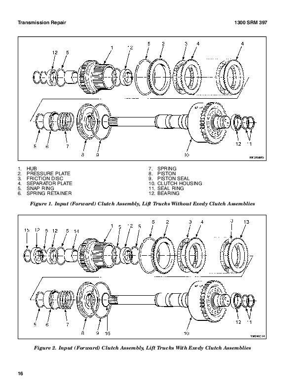
Input Shaft, Disassemble…866
Reverse Clutch, Disassemble…868
Output Shaft (Pinion) and Differential, Remove and Disassemble…871
Clean and Inspect…873
Assemble…873
Input Shaft, Assemble…874
Reverse Clutch, Assemble…882
Output Shaft (Pinion) and Differential, Assemble and Install…887
Transmission, Assemble…894
Control Valve, Install…897
Install…897
Control Valve Repair…898
Remove, Early Model S3.50-5.50XL (S70-120XL) Lift Trucks…898
Disassemble, Early Model S3.50-5.50XL (S70-120XL) Lift Trucks…898
Assemble, Early Model S3.50-5.50XL (S70-120XL) Lift Trucks…899
Install, Early Model S3.50-5.50XL (S70-120XL) Lift Trucks…899
Remove and Disassemble, Later Model S3.50-5.50XL (S70-120XL) Tru…899
Inspect, Later Model S3.50-5.50XL (S70-120XL) Trucks and S3.50-5…902
Assemble and Install, Later Model S3.50-5.50XL (S70-120XL) Truck…902
MONOTROL® Pedal Repair…904
Remove and Disassemble, S3.50-5.50XL (S70-120XL) Model Lift Truc…904
Assemble and Install, S3.50-5.50XL (S70-120XL) Model Lift Trucks…905
Remove and Disassemble, S3.50-5.50XM (S70-120XM) Model Lift Truc…907
Assemble and Install, S3.50-5.50XM (S70-120XM) Model Lift Trucks…907
Direction Control Lever Repair…909
Remove and Disassemble…909
Assemble and Install…909
Stall Test…910
Linkages Adjustment…911
Linkage for Inching/Brake Pedal, S3.50-5.50XL (S70-120XL) (D004)…911
Linkage for Direction Control Lever…913
Linkage for Inching/Brake Pedal, S3.50-5.50XM (S70-120XM) (E004,…913
Brake Shoe Adjustment…913
Inching/Brake Pedal Height Adjustment…913
Single Pedal Height Adjustment…913
Two Pedal Height Adjustment…913
Inching/Brake Linkage Adjustment…915
Oil Pressures Check…917
System Pressure Check Port…917
Torque Converter Check Port…917
Clutch Pressure Check Port…918
Inching Pressure…918
Solenoid Check Ports ( MONOTROL Control Only)…920
Lubrication Pressure Check Ports…920
System Pressure Check Port…920
Torque Converter Check Port…920
Reverse Clutch Pressure Check Port…920
Forward Clutch Pressure Check Port…920
Lubrication Pressure Check Port…920
Modulator Pressure Check Port…920
Troubleshooting…921
tables…860
Table 1. Ring and Pinion Tooth Contact Adjustment…892
Table 2. Stall Speed Specifications…910
Table 3. Transmission Oil Pressure Check, Early Model S3.50-5.50…918
Table 4. Transmission Oil Pressure Check, Later Model S3.50-5.50…919
hyster-897322-09-03-srm0399…928
toc…928
Single-Speed Powershift Transmission…928
Safety Precautions Maintenance and Repair…929
General…932
Mechanical Description…932
General…932
Torque Converter…932
Oil Pump…932
Shaft Assemblies…932
Input Shaft…932
Reverse Clutch Shaft…932
Countershaft…933
Ring Gear, Pinion, and Differential…933
Clutch Assemblies…934
Hydraulic Operation…935
Torque Converter…935
Shaft Assemblies…936
Control Valve…936
General…936
System Regulator…936
Clutch Pressure Regulator…936
Torque Converter Regulator…936
Inching Spool…936
Direction Spool, Manual Control…938
Direction Spool, MONOTROL Pedal…938
Modulation Spool…938
Accumulator…938
Drain Spool…938
MONOTROL Pedal…938
Control Valve…940
General…940
Regulator for Clutch Pressure…940
Inching Spool Assembly…940
Direction Spool…943
Direction Spool, Manual Control…944
Modulator Circuit…944
Regulator for Torque Convertor…944
Lubrication Circuit…944
Direction Control Lever…944
MONOTROL Pedal…945
Start Circuit, MONOTROL Pedal…945
Creep Speed Switch…946
Oil Flow Diagrams…946
Neutral…946
Forward…946
Forward-Inching…946
Reverse…946
hyster-897800-11-03-srm0590…962
toc…962
GM Engines…962
Safety Precautions Maintenance and Repair…963
General…966
Description…966
Engine Removal and Installation…967
Cylinder Head Repair…967
Remove and Disassemble…967
Clean and Inspect…967
Valve Guides and Seats, Repairs…968
Valves, Repair…968
Valve Seats, Repair…969
Valve Springs…970
Rocker Arm Studs (Early Models)…970
Rocker Arm Studs (Late Models)…971
Assemble and Install…971
Cylinder Block Cleaning and Inspection…975
Piston Bore Preparation…975
Engine Mounts Installation…975
Lubrication System Repair…976
Oil Pump, Remove and Disassemble…976
Clean and Inspect…976
Oil Pump, Assemble and Install…976
Oil Sump, Install…977
Timing Cover, Timing Sprockets, Camshaft, and Valve Lifters…978
Timing Cover…978
Remove…978
Install…980
Timing Sprockets…980
Remove…980
Install…980
Camshaft…981
Remove…981
Inspect…981
Install…981
Balance Shaft…982
Remove…982
Install…983
Hydraulic Valve Lifters…983
Remove…983
Disassemble…984
Clean and Inspect…984
Assemble…984
Install…985
Crankshaft Repair…986
Remove…986
Inspect and Repair…986
How to Check Clearance Between Main Bearings and Their Journals…987
Install…988
Piston and Connecting Rod Assemblies Repair…989
Connecting Rod Bearings, Replace…989
Piston and Connecting Rod Assemblies, Remove…990
Disassemble…990
Piston, Clean and Inspect…991
Cylinder Bores, Inspect and Repair…991
Piston Rings…992
Assemble…993
Piston and Connecting Rod Assemblies, Install…993
Flywheel and Flywheel Housing Repair…994
Flywheel, Repair…994
Flywheel, Install…994
H3.50-5.00XL (H70-110XL), S3.50-5.50XL (S70-120XL), S6.00-7.00XL…994
H6.00-7.00XL (H135-155XL)…994
Flywheel Housing H3.50-5.00XL (H70-110XL), H3.50-5.50XM (H70-120…994
Engine Adapter H6.00-7.00XL (H135-155XL)…994
Coolant Pump Repair…995
Thermostat Replacement…995
Fan Mount Repair (Early Models)…995
Fan Mount Assembly Repair (Late Models)…995
Drive Belt Installation…997
Valve Clearance Adjustment (Early Models)…998
Valve Clearance Adjustment (New Models)…999
Compression Check…999
Engine Specifications…999
Engine Data…999
Cylinder Head…1000
Hydraulic Valve Lifter…1000
Camshaft…1000
Pistons…1000
Crankshaft…1001
Connecting Rods…1002
Balance Shaft…1002
Cooling System…1002
Lubrication System…1002
Torque Specifications…1003
Troubleshooting…1004
tables…962
Table 1. Piston Rings Arrangement on Piston…993
hyster-897934-11-01-srm0626…1010
toc…1010
Cooling System…1010
Safety Precautions Maintenance and Repair…1011
General…1014
Description…1015
Radiator…1015
Radiator Cap…1015
Thermostat…1015
Water Pump…1016
Fan and Fan Shroud…1016
Cooling System Checks…1016
Radiator…1016
Thermostat…1016
Water Pump…1017
Exhaust Leaks…1017
Fan and Fan Shroud…1017
Radiator Cleaning…1017
Drain…1017
Clean…1017
Fill…1018
Troubleshooting…1019
hyster-899784-10-03-srm0002…1022
toc…1022
Alternator with Regulator…1022
Safety Precautions Maintenance and Repair…1023
General…1026
Description…1026
Alternator Repair…1028
Alternator Type A…1028
Remove and Disassemble…1028
Clean…1029
Assemble…1030
Install…1030
Alternator Type B…1033
Remove and Disassemble…1033
Clean…1033
Assemble…1034
Install…1035
General Check and Adjustment…1036
Low Output Check (Type A or Type B)…1036
High Output Check (Type A or Type B)…1038
Brushes Circuit Check…1039
Delco Alternators…1039
Motorola Alternators…1040
Diodes Check…1041
Diode Bridge Check…1041
Delco and Leece-Neville Alternators…1041
Motorola Alternators…1041
Rotor Field Winding Check…1042
Stator Windings Check…1043
Voltage Regulator Check…1043
Troubleshooting…1043
hyster-910091-10-03-srm0097…1048
toc…1048
Hydraulic Gear Pumps…1048
Safety Precautions Maintenance and Repair…1049
Description…1052
Operation…1053
Flow Control Valve…1053
Relief Valve…1054
Hydraulic Gear Pump Repair…1054
Remove…1054
Disassemble…1055
Clean…1055
Inspect…1056
Assemble…1059
Install…1061
Pump Output Check…1061
Method No. 1…1061
Method No. 2…1062
Hydraulic System Air Check…1063
Troubleshooting…1064
hyster-910442-03-03-srm0231…1070
toc…1070
Metric and Inch (SAE) Fasteners…1070
Safety Precautions Maintenance and Repair…1071
General…1074
Threaded Fasteners…1074
Nomenclature, Threads…1074
Strength Identification…1075
Cotter (Split) Pins…1075
Fastener Torque Tables…1080
Conversion Table…1082
tables…1070
Table 1. Bolts and Screws…1076
Table 2. Studs and Nuts…1077
Table 3. Torque Nuts…1078
Table 4. Torque Nuts With Nylon Insert…1079
Table 5. Torque Values for Metric Fasteners*…1080
Table 6. Torque Values for Inch Fasteners*…1081
Table 7. Conversion Table for Metric and English units…1082
Table 8. Cotter Pin Dimensional Data…1083
Hyster S70-120XM (F004) Repair Service Manual