Complete Repair Service Technical Manual for John Deere 5075GV, 5090GV, 5075GN, 5090GN, 5105GN, 5075GF, 5090GF, 5105GF, 5075GL, 5090GL, 5100GL Tractors, with all the shop information to maintain, repair, and rebuild like professional mechanics.
John Deere 5075GV, 5090GV, 5075GN, 5090GN, 5105GN, 5075GF, 5090GF, 5105GF, 5075GL, 5090GL and 5100GL (MY17- ) Tractors workshop technical manual (repair) includes:
* Numbered table of contents easy to use so that you can find the information you need fast.
* Detailed sub-steps expand on repair procedure information
* Numbered instructions guide you through every repair procedure step by step.
* Notes, cautions and warnings throughout each chapter pinpoint critical information.
* Bold figure number help you quickly match illustrations with instructions.
* Detailed illustrations, drawings and photos guide you through every procedure.
* Enlarged inset helps you identify and examine parts in detail.
tm410019 – John Deere 5075GV, 5090GV, 5075GN, 5090GN, 5105GN, 5075GF, 5090GF, 5105GF, 5075GL, 5090GL and 5100GL (MY17- ) Tractors Repair (European Edition) Technical Manual.pdf
tm410028 – Remise en état des tracteurs 5075GV, 5090GV, 5075GN, 5090GN, 5105GN, 5075GF, 5090GF, 5105GF, 5075GL, 5090GL et 5100GL (AM17- ) -: (Édition européenne) French.pdf
tm410029 – Reparatur der Traktoren 5075GV, 5090GV, 5075GN, 5090GN, 5105GN, 5075GF, 5090GF, 5105GF, 5075GL, 5090GL und 5100GL (ab Modelljahr 2017) -: (Europäische Versionen) German.pdf
tm410030 – Επισκευή τρακτέρ 5075GV, 5090GV, 5075GN, 5090GN, 5105GN, 5075GF, 5090GF, 5105GF, 5075GL, 5090GL και 5100GL (MY17- ) -: (Ευρωπαϊκή έκδοση) Greek.pdf
tm410039 – Riparazione trattori 5075GV, 5090GV, 5075GN, 5090GN, 5105GN, 5075GF, 5090GF, 5105GF, 5075GL, 5090GL e 5100GL (anno 2017 e successivi) -: (Versione europea) Italian.pdf
tm410054 – Reparação dos Tratores 5075GV, 5090GV, 5075GN, 5090GN, 5105GN, 5075GF, 5090GF, 5105GF, 5075GL, 5090GL e 5100GL (Ano-modelo 2017- ) -: (Edição Europeia) Portuguese.pdf
tm410080 – 5075GV, 5090GV, 5075GN, 5090GN, 5105GN, 5075GF, 5090GF, 5105GF, 5075GL, 5090GL ve 5100GL (MY17- ) Traktörler Onarım -: (Avrupa Sürümü) Turkish.pdf
PRODUCT DETAILS:
Total Pages: 2,720 pages
File Format: PDF/EPUB/MOBI/AZW (PC/Mac/Android/Kindle/iPhone/iPad; bookmarked, ToC, Searchable, Printable)
Language: English
TABLE OF CONTENTS…………….1
Section 05: Safety…………….30
Group 05: Safety Measures…………….30
Recognize Safety Information…………….33
Understand Signal Words…………….34
Follow Safety Instructions…………….35
Prepare for Emergencies…………….36
Wear Protective Clothing…………….37
Protect Against Noise…………….38
Handle Fuel Safely—Avoid Fires…………….39
Fire Prevention…………….40
In Case of Fire…………….41
Avoid Static Electricity Risk When Refueling…………….42
Use Foldable ROPS and Seat Belt Properly…………….44
Stay Clear of Rotating Drivelines…………….45
Use Steps and Handholds Correctly…………….47
Read Operator’s Manuals for ISOBUS Controllers…………….48
Use Seat Belt Properly…………….49
Vibration…………….50
Operating the Tractor Safely…………….51
Avoid Backover Accidents…………….53
Limited Use in Forestry Operation…………….54
Operating the Loader Tractor Safely…………….55
Keep Riders Off Machine…………….56
Passenger Seat…………….57
Use Safety Lights and Devices…………….58
Towing Trailers/Implements Safely…………….59
Use Caution on Slopes, Uneven Terrain, and Rough Ground…………….60
Freeing a Mired Machine…………….61
Avoid Contact with Agricultural Chemicals…………….62
Handle Agricultural Chemicals Safely…………….63
Handling Batteries Safely…………….65
Avoid Heating Near Pressurized Fluid Lines…………….67
Remove Paint Before Welding or Heating…………….68
Handle Electronic Components and Brackets Safely…………….69
Practice Safe Maintenance…………….70
Avoid Hot Exhaust…………….72
Clean Exhaust Filter Safely…………….73
Work In Ventilated Area…………….76
Support Machine Properly…………….77
Prevent Machine Runaway…………….78
Park Machine Safely…………….79
Transport Tractor Safely…………….80
Service Cooling System Safely…………….81
Service Accumulator Systems Safely…………….82
Service Tires Safely…………….83
Service Front-Wheel Drive Tractor Safely…………….84
Tightening Wheel Retaining Bolts/Nuts…………….85
Avoid High-Pressure Fluids…………….86
Do Not Open High-Pressure Fuel System…………….108
Store Attachments Safely…………….88
Decommissioning — Proper Recycling and Disposal of Fluids and Components…………….89
Section 10: General Information…………….2240
Group 05: Specifications – General Information…………….2240
Summary of References – Specifications – General Information…………….2240
Engine…………….97
Transmission…………….99
Front-Wheel Drive Clutch…………….100
Hydraulic System…………….101
Electrical System…………….102
Capacities…………….103
Sound Level…………….105
Fuel System…………….108
Brakes…………….109
Three-Point Hitch…………….110
Loads and Weights…………….111
Maximum Lifting Force…………….118
Towable Loads…………….119
Front Weights…………….120
Tire Combinations…………….122
Shipping Weights…………….129
Maximum Permissible Axle Loads and Total Weights…………….130
Maximum Permissible Axle Load in Relation to Tires (Normal Operation)…………….131
Load Capacity of Tires with Front Loader…………….145
Vehicle Dimensions…………….146
Safety Note Regarding the Subsequent Installation of Electrical and Electronic Appliances and/or Components…………….152
How to Calculate Maximum Permissible Download on Trailer Hitch…………….153
How to Calculate Permissible Mass…………….155
Observe Rear Wheel Tread Width Limitations…………….156
Limited Battery Warranty…………….159
Metric Bolt and Screw Torque Values…………….161
Unified Inch Bolt and Screw Torque Values…………….163
Diesel Fuel…………….165
Handling and Storing Diesel Fuel…………….166
Do Not Use Galvanized Containers…………….167
Fill Fuel Tank…………….168
Diesel Engine Break-In Oil — Non-Emissions Certified and Certified Tier 1, Tier 2, Tier 3, Stage I, Stage II, and Stage III…………….170
Diesel Engine Oil — Tier 2 and Stage II…………….172
Transmission and Hydraulic Oil…………….174
Front-Wheel Drive Axle and Rear Drop Axle Oil…………….175
Multipurpose Extreme Pressure (EP) Grease…………….176
Oil Filters…………….177
Lubricant Storage…………….178
Mixing of Lubricants…………….179
Diesel Engine Coolant…………….180
Operating in Warm Temperature Climates…………….181
Alternative and Synthetic Lubricants…………….182
Identification Plates…………….183
Vehicle Identification Number (VIN)…………….184
Product Identification Number Plates…………….185
Safety Structure Plates…………….186
Engine Serial Number…………….188
Fuel Injection Pump Serial Number Location…………….189
Power Steering Valve Serial Number Location…………….190
Air-Conditioning Compressor Serial Number Location…………….191
Transmission Serial Number Location…………….192
Front Axle Serial Number…………….193
Front-Wheel Drive Serial Number…………….195
Front Suspended Axle Serial Number (MY20)…………….196
Group 10: Tune-Up…………….91
Summary of References – Tune-Up…………….198
Using High-Pressure Washers…………….199
Preliminary engine test…………….200
Clean Radiator and Oil Cooler…………….201
Radiators Cleaning (5G VNF)…………….203
Radiators Cleaning (5GL)…………….207
Clean Air-Conditioning System Condenser (5G VNF)…………….210
Clean Air-Conditioning System Condenser (5GL) (Cab)…………….211
Check Hoses and Hose Clamps…………….213
Check Blow-By Hose…………….215
Clean the Dust Unloading Valve…………….217
Engine Air Filter…………….218
Cleaning the Primary Filter Element…………….220
Cleaning a Dusty Element…………….221
Secondary (Safety) Element…………….222
Clean Cab Air Filters (5G VNF)…………….223
Clean Low Profile Cab Air Filters (5GL)…………….224
Check Engine Oil Level…………….226
Check Brake System Oil Level…………….227
Check Coolant Level…………….229
Check Transmission/Hydraulic System Oil Level…………….231
Check the Fuel Filter…………….232
Starter Motor…………….235
Battery – Checking Specific Gravity…………….236
Check Neutral Start System (5G VNF)…………….238
Check Neutral Start System (5G VNF) (MY20)…………….240
Check Neutral Start System (5GL)…………….242
Check Setting of Head Lights and Work Lights…………….244
Check Lights…………….245
Final Engine Check…………….246
Tractor Operation Check…………….247
Group 15: Predelivery Inspection…………….250
Summary of References – Predelivery Inspection…………….250
Predelivery Inspection…………….250
Section 20: Engine…………….253
Group 00: Removal and Installation of Engine Components…………….253
Summary of References – Remove and Install Engine Components…………….256
Engine Repair…………….257
Specifications – Engine…………….258
Remove Engine (5G VNF)…………….259
Remove Engine (5GL)…………….272
Install Engine (5G VNF)…………….280
Install Engine (5GL)…………….285
Water Pump Repair…………….290
Remove and Inspect Radiator (5G VNF)…………….291
Remove and Inspect Radiator (5GL)…………….302
Install Radiator…………….310
Remove Oil Cooler…………….312
Install Oil Cooler…………….317
Replace Thermostat Valve…………….318
Remove Engine Side Panels (5G VNF)…………….321
Remove Engine Side Panels (5GL)…………….323
Install Engine Side Panels (5G VNF)…………….325
Install Engine Side Panels (5GL)…………….327
Vertical Exhaust Pipe CAB Post Disassembly (5G VNF)…………….329
Horizontal (Venturi) Exhaust Pipe Disassembly (5G VNF)…………….332
Horizontal Exhaust Pipe Disassembly (5GL)…………….335
Remove DPF Module (5G VNF)…………….339
Remove DPF Module (5GL)…………….342
Install DPF Module (5G VNF)…………….349
Install DPF Module (5GL)…………….350
Replace DPF Exhaust Pipe (5G VNF)…………….351
Replace DPF Exhaust Pipe (5GL)…………….354
Separate Engine from Support Front Axle (5G VNF)…………….358
Separate Engine from Support Front Axle (5GL)…………….374
Install Engine on Support Front Axle (5G VNF)…………….386
Install Engine on Support Front Axle (5GL)…………….388
A500 – Remove and Install Engine ECU…………….391
Section 30: Fuel and Air Intake Systems…………….399
Group 05: Speed Control Linkage…………….399
Summary of References – Speed Control Linkage…………….401
Hand Throttle Calibration (5G VNF)…………….402
Hand Throttle Calibration (5GL)…………….406
Foot Throttle Calibration (5G VNF)…………….410
Foot Throttle Calibration (5GL)…………….414
Remove and Install Hand Throttle Lever…………….418
Remove and Install Foot Throttle Pedal (5G VNF)…………….420
Remove and Install Foot Throttle Pedal (5GL)…………….424
Group 10: Fuel System…………….108
Fuel System – Summary of References…………….428
Injection Pump, Nozzle and Governor Repair…………….429
Drain Fuel Tank…………….430
Remove, Inspect, and Install Fuel Tank (5G VNF)…………….431
Remove, Inspect, and Install Fuel Tank (5GL)…………….440
Remove, Inspect, and Install Auxiliary Fuel Tank (5G VNF)…………….446
Replace Fuel Filter…………….451
Bleed Fuel System…………….454
Remove, Inspect, and Install Fuel Cooler (5G VNF)…………….456
Remove, Inspect, and Install Fuel Cooler (5GL)…………….459
Group 15: Air Intake System…………….399
Summary of References – Air Intake System…………….462
Turbocharger Repair…………….463
Remove and Install Air Cleaner Element…………….464
Remove and Install Air Filter Housing (5G VNF)…………….466
Remove and Install Air Filter Housing (5GL)…………….469
Remove and Install Air Intake Hoses (5G VNF)…………….473
Remove and Install Air Intake Hoses (5GL)…………….477
Air Filter Housing – System Components…………….480
Remove, Inspect, and Install Air Cooler (5G VNF)…………….481
Remove, Inspect, and Install Air Cooler (5GL)…………….485
Section 40: Electrical System…………….490
Group 05: Battery, Starter Motor, and Alternator…………….490
Battery, Starter Motor, and Alternator – Summary of References…………….493
M01 – Starter Motor Repair…………….494
G01 – Disconnect Battery…………….495
G01 – Connect Battery…………….496
G01 – Remove Battery…………….497
G01 – Install Battery…………….498
S900 – Battery Cut-off Switch…………….499
G01 – Remove and Install Battery (5G VNF)…………….501
G01 – Remove and Install Battery (5G VNF) (MY20)…………….503
G01 – Remove and Install Battery (5GL)…………….506
M01 – Remove and Install Starter Motor (5G VNF)…………….509
M01 – Remove and Install Starter Motor (5GL)…………….511
G02 – Alternator/Regulator Repair…………….513
G02 – Replace Alternator/Regulator…………….514
Check Belt Wear and Tension…………….518
Group 10: Switches and Sensors…………….490
Summary of References – Switches and Sensors…………….522
B02 – Replace Air Filter Restriction Sensor…………….523
B03 – Replace Fuel Level Sensor…………….525
B05 – Replace Park Brake Switch…………….529
B06 – Replace Transmission Speed Sensor…………….531
B07/1 – Replace PTO Switch (540 rpm)…………….533
B07/2 – Replace PTO Switch (540E/1000 rpm)…………….534
B08 – Replace PTO Neutral Start Switch…………….535
B36 – Replace Neutral Start Switch…………….537
B69 – Replace Brake Oil Level Sensor…………….538
B112 – Replace Brake Pedal Switches…………….540
B150 – Replace Thermostat (5G VNF)…………….544
B150 – Replace Thermostat (5GL) (Cab)…………….545
B151 – Replace Fan Resistor (5G VNF)…………….550
B151 – Replace Fan Resistor (5GL) (Cab)…………….552
B304 – Replace Refrigerant Pressure Sensor (5G VNF)…………….557
B304 – Replace Refrigerant Pressure Sensor (5GL) (Cab)…………….558
S01 – Replace Main Switch (5G VNF)…………….562
S01 – Replace Main Switch (5GL)…………….564
S09 – Replace Multi-Function Lever (5G VNF)…………….566
S09 – Replace Multi-Function Lever (5GL)…………….568
S21/1 – Replace Ground Drive PTO Selector Switch…………….570
S106 – Replace Hazard Warning Light Switch (5G VNF)…………….572
S106 – Replace Hazard Warning Light Switch (5GL)…………….573
Replace Turn Signal Lights Blinker Unit (5G VNF)…………….575
Replace Turn Signal Lights Blinker Unit (5GL)…………….577
Replace Instrument Panel Switches (5G VNF)…………….579
Replace Instrument Panel Switches (5GL)…………….581
K01 – Replace Starter Motor Relay (5G VNF)…………….583
K01 – Replace Starter Motor Relay (5GL)…………….584
Remove and Install Dashboard Cowls (5G VNF)…………….586
Remove and Install Dashboard Cowls (5GL)…………….591
B998 – Replace Hand Throttle Lever Potentiometer…………….598
Replace Glow Plug GCU ECU (5G VNF)…………….601
Replace Glow Plug GCU ECU (5GL)…………….603
Section 50A: Drive Train (without Transmission)…………….604
Group 00: Component Removal and Installation…………….604
Summary of References – Drive Systems – Component Removal and Installation…………….608
Specifications – Drive Systems…………….609
Essential or Recommended Tools…………….2615
Remove and Install Front-Wheel Drive Clutch (5G VNF)…………….611
Remove and Install Front-Wheel Drive Clutch (5GL)…………….613
Remove and Install Differential Assembly…………….615
Remove and Install Final Drive Assembly (5G VNF)…………….619
Remove and Install Final Drive Assembly (5GL)…………….623
Remove Rear PTO Cover…………….627
Install Rear PTO Cover…………….630
Group 15: Front-Wheel Drive Clutch – Transmission…………….99
Summary of References – Front-Wheel Drive Clutch…………….634
Specifications – Front-Wheel Drive Clutch – Transmission…………….635
Disassemble and Inspect Front-Wheel Drive Clutch (5G VNF)…………….636
Disassemble and Inspect Front-Wheel Drive Clutch — Hydraulically Operated (5GL)…………….644
Front-Wheel Drive Clutch Cross Section (5G VNF)…………….646
Front-Wheel Drive Clutch Cross Section — Hydraulic Operated (5GL)…………….648
Assemble Front-Wheel Drive Clutch (5G VNF)…………….650
Assemble Front-Wheel Drive Clutch — Hydraulically Operated (5GL)…………….661
Group 20: Differential…………….604
Summary of References – Differential…………….668
Essential Tools…………….669
Service Equipment and Tools…………….670
Essential or Recommended Tools…………….2615
Specifications – Differential…………….672
Disassemble, Inspect, and Assemble Four Pinion Differential Assembly…………….673
Four Pinion Differential Backlash Adjustment…………….677
Four Pinion Differential Bearing Preload Adjustment…………….679
Inspect and Repair Hydraulic Differential Lock and Linkage…………….681
Remove, Inspect, and Install Differential Lock Assembly…………….683
Group 25: Final Drives…………….605
Summary of References – Final Drives…………….690
Specifications – Final Drives…………….691
Essential or Recommended Tools…………….2615
Remove and Inspect Planetary Drive Assembly…………….693
Install Planetary Drive Assembly…………….695
Remove, Inspect, and Install Axle Shaft Assembly…………….698
Group 30: Power Take-Off…………….605
Summary of References – Power Take-Off…………….703
Special Tools – Power Take-Off…………….704
Essential or Recommended Tools…………….2615
Inspect and Repair Rear PTO Clutch Lever and Linkage…………….706
Remove, Inspect, and Install Hydraulic PTO Clutch Cylinder Assembly…………….708
Disassemble, Inspect, and Assemble PTO Shift Leverage Assembly…………….711
Disassemble, Inspect, and Assemble Rear PTO Engagement Control…………….714
Disassemble, Inspect, and Assemble Rear PTO Drive Shaft Assembly…………….716
Disassemble, Inspect, and Assemble Ground Drive PTO Control Assembly…………….719
Disassemble, Inspect, and Assemble Rear PTO Engagement Sleeve…………….722
Remove and Install Rear PTO Drive Shaft…………….725
Disassemble Electro-Hydraulic Rear PTO Cover…………….727
Assemble Electro-Hydraulic Rear PTO Cover…………….730
Disassemble Electro-Hydraulic Rear PTO Clutch Drive Shaft…………….734
Assemble Electro-Hydraulic Rear PTO Clutch Drive Shaft…………….739
Remove Electro-Hydraulic Rear PTO Drive Shaft…………….744
Disassemble Electro-Hydraulic Rear PTO Drive Shaft…………….745
Assemble Electro-Hydraulic Rear PTO Drive Shaft…………….748
Install Electro-Hydraulic Rear PTO Drive Shaft…………….752
Remove Electro-Hydraulic Rear PTO Input Shaft…………….753
Disassemble and Assemble Electro-Hydraulic Rear PTO Input Shaft…………….754
Install Electro-Hydraulic Rear PTO Input Shaft…………….755
Remove Electro-Hydraulic Rear PTO Brake…………….756
Disassemble Electro-Hydraulic Rear PTO Brake…………….758
Assemble Electro-Hydraulic Rear PTO Brake…………….762
Install Electro-Hydraulic Rear PTO Brake…………….767
Group 35: Transmission Housing – Sensors…………….606
B06 – Remove, Inspect and Install Transmission Speed Sensor…………….774
Section 50B: Mechanical Transmissions…………….778
Group 00: Removal and Installation of Power Train Components…………….778
Summary of References – Power Train Components…………….781
Specifications – Power Train Components…………….782
Essential or Recommended Tools…………….2615
Separate Engine from Clutch Housing (5G VNF)…………….784
Separate Engine from Clutch Housing (5GL)…………….802
Separate Engine from Clutch Housing (5GL) (Cab)…………….818
Install Engine on Clutch Housing (5G VNF)…………….833
Install Engine on Clutch Housing (5GL)…………….838
Separate Clutch Housing from Transmission – for 12/12 and 24/24 Speed Transmission…………….843
Install Clutch Housing on Transmission – for 12/12 and 24/24 Speed Transmission…………….848
Replace Clutch Housing Seal – 12/12 Speed Transmission…………….853
Replace Clutch Housing Seal – 24/24 Speed Transmission…………….854
Group 05: Clutch…………….778
Summary of References – Clutch…………….859
Specifications – Clutch…………….860
Essential or Recommended Tools…………….2615
Inspect and Repair Clutch Pedal and Linkage…………….862
Remove and Install Clutch Assembly…………….864
Disassemble and Inspect Clutch Assembly…………….868
Assemble Clutch Assembly…………….877
Traction Clutch Finger Adjustment…………….883
PTO Clutch Finger Adjustment…………….885
Remove and Inspect Clutch Release Mechanism…………….887
Install Clutch Release Mechanism…………….890
Remove and Install Flywheel…………….893
Group 10: Hi-Lo Clutch (24/24-Speed Transmission)…………….778
Summary of References – Hi-Lo Clutch (24/24-Speed Transmission)…………….897
Essential or Recommended Tools…………….2615
Specifications – Hi-Lo Clutch (24/24-Speed Transmission)…………….899
Remove and Inspect Mechanical Hi-Lo Drive…………….900
Install Mechanical Hi-Lo Drive…………….903
Disassemble, Inspect and Assemble Mechanical Hi-Lo Shift Shaft Assembly…………….906
Disassemble, Inspect and Assemble Mechanical Hi-Lo Synchronizer…………….908
Disassemble, Inspect and Assemble Mechanical Hi-Lo Drive Shaft…………….910
Disassemble, Inspect and Assemble Mechanical Hi-Lo Reduction Shaft…………….912
Inspect and Repair Mechanical Hi-Lo Shift Lever (5G VNF)…………….914
Inspect and Repair Mechanical Hi-Lo Shift Lever (5GL)…………….916
Seal Ring Replacement of Hydraulic Hi-Lo Clutch Drive Shaft…………….918
Remove and Inspect Hydraulic Hi-Lo Clutch Assembly…………….924
Install Hydraulic Hi-Lo Clutch Assembly…………….927
Disassemble, Inspect and Assemble Hydraulic Hi-Lo Clutch…………….931
Disassemble, Inspect and Assemble Hydraulic Hi-Lo Drive Shaft…………….935
Group 20: Transmission…………….99
Summary of References – Transmission…………….938
Specifications – Transmission…………….939
Essential or Recommended Tools…………….2615
Remove and Install Transmission…………….942
Inspect and Repair Gear and Range Shift Levers…………….944
Remove, Inspect, and Install Range Shaft…………….948
Range Shaft End Play Adjustment…………….954
Remove, Inspect, and Install Primary and Reverse Shafts…………….955
Primary Shaft End Play Adjustment…………….968
Remove, Inspect, and Install Pinion Shaft…………….970
Pinion Shaft Cone Point Adjustment…………….977
Pinion Bearing Preload Adjustment…………….979
Remove, Inspect, and Install Secondary Shaft…………….982
Secondary Shaft End Play Adjustment…………….994
Section 50C: Power Reverser Transmission (24-12)…………….998
Group 00: Removal and Installation of Components – 24/12-Speed Transmission…………….99
Removal and Installation of Components – 24/12-Speed Transmission, Summary of References…………….1001
Removal and Installation of Components – 24/12-Speed Transmission, Specifications…………….2549
Removal and Installation of Components – 24/12-Speed Transmission, Special Tools…………….1003
Essential or Recommended Tools…………….2615
Separate Clutch Housing from Transmission – 24/12-Speed Transmission…………….1005
Install Clutch Housing on Transmission – 24/12-Speed Transmission…………….1010
Guide of Forward High Clutch Drive Shaft and Cover of Forward Low/Reverse Clutch Drive Shaft – 24/12-Speed Transmission…………….1015
Remove Guide of Forward High Clutch Drive Shaft – 24/12-Speed Transmission…………….1017
Replace Seal Rings of Forward High Clutch Drive Shaft – 24/12-Speed Transmission…………….1019
Install Guide of Forward High Clutch Drive Shaft – 24/12-Speed Transmission…………….1020
Remove Cover of Forward Low/Reverse Clutch Drive Shaft – 24/12-Speed Transmission…………….1024
Replace Seal Rings of Forward Low/Reverse Clutch Drive Shaft – 24/12-Speed Transmission…………….1026
Install Cover of Forward Low/Reverse Clutch Drive Shaft – 24/12-Speed Transmission…………….1029
Remove Air Pump – 24/12-Speed Transmission…………….1032
Install Air Pump – 24/12-Speed Transmission…………….1034
Group 15: Electro-Hydraulic Forward High/Low and Reverse Clutch – 24/12-Speed Transmission…………….99
Electro-Hydraulic Forward High/Low and Reverse Clutch – 24/12-Speed Transmission, Summary of References…………….1037
Electro-Hydraulic Forward High/Low and Reverse Clutch – 24/12-Speed Transmission, Specifications…………….2549
Essential or Recommended Tools…………….2615
Remove Electro-Hydraulic Forward High/Low and Reverse Clutch Assembly – 24/12-Speed Transmission…………….1040
Install Electro-Hydraulic Forward High/Low and Reverse Clutch Assembly – 24/12-Speed Transmission…………….1042
Disassemble, Inspect, and Assemble Electro-Hydraulic Forward High Clutch – 24/12-Speed Transmission…………….1046
Disassemble, Inspect, and Assemble Electro-Hydraulic Forward Low Clutch – 24/12-Speed Transmission…………….1052
Disassemble, Inspect, and Assemble Electro-Hydraulic Reverse Clutch – 24/12-Speed Transmission…………….1058
Remove Secondary Shaft Assembly – 24/12-Speed Transmission…………….1065
Disassemble, Inspect, and Assemble Secondary Shaft Assembly – 24/12-Speed Transmission…………….1066
Install Secondary Shaft Assembly – 24/12-Speed Transmission…………….1071
Remove Drive Shaft Assembly – 24/12-Speed Transmission…………….1072
Replace Clutch Housing Seal – 24/12-Speed Transmission…………….1073
Disassemble, Inspect, and Assemble Drive Shaft Assembly – 24/12-Speed Transmission…………….1074
Install Drive Shaft Assembly – 24/12-Speed Transmission…………….1078
Section 60: Steering and Brake Systems…………….1079
Group 05: Steering System…………….1079
Summary of References – Steering System…………….1082
Specifications – Steering System…………….1083
Remove and Install Steering Wheel (5G VNF)…………….1085
Remove and Install Steering Wheel (5GL)…………….1088
Remove and Install Steering Column (5G VNF)…………….1090
Remove and Install Steering Column (5GL)…………….1096
Remove and Install Power Steering Valve (5G VNF)…………….1100
Remove Power Steering Valve (5GL)…………….1103
Remove and Install Steering Cylinder (5G VNF)…………….1105
Remove and Install Steering Cylinder (5GL)…………….1107
Remove and Install Steering Cylinder (Two-Wheel Drive Tractors) (5G VNF)…………….1109
Disassemble, Inspect, and Assemble Steering Cylinder (5G VNF)…………….1111
B979 – Remove and Install Wheel Angle Sensor (5G VNF)…………….1115
Remove, Inspect, and Install Tie Rod Assembly (5G VNF)…………….1121
Steering System (5GL)…………….1126
Group 10: Brake System…………….1079
Summary of References – Brake System…………….1135
Specifications – Brake System…………….1136
Essential or Recommended Tools…………….2615
Change Brake System Oil…………….1138
Remove and Install Brake Pump and Pedals…………….1144
Disassemble and Inspect Brake Pedals…………….1152
Brake Cylinders Cross Section…………….1153
Remove and Inspect Brakes…………….1154
Install Brakes…………….1157
Inspect and Replace Brake Hydraulic Lines…………….1160
Remove, Inspect, and Install Brake Linkage…………….1164
Remove, Inspect, and Install Park Brake Lever…………….1168
Remove, Inspect, and Install Park Brake Linkage…………….1172
Park Brake Adjustment…………….1184
Remove Brake Pump…………….1187
Install Brake Pump…………….1194
Bleed Brake System (5G VNF)…………….1197
Bleed Brake System (5G VNF) (MY20)…………….1203
Bleed Brake System (5GL) (MY20)…………….1207
Bleed Brake System (5GL)…………….1211
Bleed Trailer Brake Valve (5G VNF)…………….1216
Remove and Install Brake Oil Reservoir…………….1221
Trailer Brake Valve System Components…………….1225
Trailer Brake Valve – Layout of Hydraulic Components (MY20)…………….1228
Trailer Brake Valve – Hydraulic Connection Ports (MY20)…………….1230
Remove and Install Trailer Brake Valve…………….1231
Remove and Install Trailer Brake Valve (5G VNF) (MY20)…………….1235
Remove and Install Trailer Brake Valve (5GL) (MY20)…………….1237
Section 70: Hydraulic System…………….1239
Group 05: Hydraulic Pump and Filter…………….1239
Summary of References – Hydraulic Pump and Filter…………….1242
Specifications – Hydraulic Pump and Filter…………….1243
Essential or Recommended Tools…………….2615
Remove and Install Hydraulic Pump…………….1245
Remove Hydraulic Pump External Components…………….1252
Install Hydraulic Pump External Components…………….1256
Replace Hydraulic Filter/Manifold…………….1258
Replace Transmission/Hydraulic Oil Filter Assembly (5G VNF)…………….1260
Replace Transmission/Hydraulic Oil Filter Assembly (5GL)…………….1263
Replace Transmission/Hydraulic Oil Filter Cartridge…………….1267
Inspect and Replace Hydraulic Suction Lines…………….1272
Inspect and Replace Hydraulic Supply Lines…………….1273
Group 10: Hitch…………….1239
Summary of References – Hitch…………….1277
Essential or Recommended Tools…………….2615
Specifications – Hitch…………….1279
Inspect and Repair Hitch Control Lever and Linkage…………….1280
Remove, Inspect, and Install Hitch Valve…………….1282
Safety and Relief Valve Adjustment…………….1287
Remove, Inspect, and Install Draft and Position Sensing Linkage…………….1289
Sensing Spring Adjustment…………….1292
Remove and Install Rockshaft Assembly…………….1293
Remove, Inspect, and Install Lift Arms and Cylinder of Rockshaft Assembly…………….1297
Remove Hitch Control Linkage…………….1300
Inspect and Repair Hitch Control Linkage…………….1303
Install Hitch Control Linkage…………….1306
Hitch Sensitivity Adjustment…………….1309
Rockshaft Position Control Lever Adjustment…………….1310
Rockshaft Draft Control Lever Adjustment…………….1312
Distributor Control Valve Adjustment…………….1314
Remove, Inspect and Install Draft and Position Sensing Linkage (EHS II)…………….1316
Rockshaft Draft and Position Adjustment (EHS II)…………….1321
Remove and Install Pressure Relief Valve…………….1324
Remove, Inspect, and Install Hitch Solenoid Valve (EHS II)…………….1327
Remove, Inspect, and Install Hitch Raise Solenoid Valve Detent…………….1346
Remove, Inspect, and Install Rockshaft Position Control Lever…………….1352
Remove, Inspect, and Install Rockshaft Draft Control Lever…………….1354
Shock Valve Adjustment…………….1358
Group 15: Three-Point Hitch…………….110
Summary of References – Three-Point Hitch…………….1362
Essential or Recommended Tools…………….2615
Inspect and Repair Draft Links…………….1364
Inspect and Repair Adjustable Lift Link…………….1366
Inspect and Repair Hydraulically Adjustable Lift Link…………….1368
Inspect and Repair Center Link…………….1370
Group 20: Selective Control Valves…………….1240
Summary of References – Selective Control Valves…………….1373
Essential or Recommended Tools…………….2615
Selective Control Valve and Lever Assembly…………….1375
Remove and Install Selective Control Valve (SCV)…………….1379
Remove and Install Selective Control Valve (SCV) – Tractors with Mid-Mounted Couplers…………….1381
Selective Control Valve Levers – Exploded View (5G VNF) (MY20)…………….1384
Selective Control Valve Levers – Exploded View (5GL) (MY20)…………….1386
Section 80A: Miscellaneous…………….1388
Group 00: Removal and Installation of Components…………….1388
Summary of References – Removal and Installation of Components (Miscellaneous)…………….1394
Specifications – Miscellaneous…………….1395
Essential or Recommended Tools…………….2615
Remove Hood…………….1397
Install Hood…………….1400
Remove, Inspect, and Install Front Axle Drive Shaft (5G VNF)…………….1401
Remove, Inspect, and Install Front Axle Drive Shaft (5GL)…………….1404
Remove and Install Front Axle (Two-Wheel Drive Tractors) (5G VNF)…………….1408
Remove and Install Front Axle – Four Wheel Drive (V and N Tractors)…………….1410
Remove and Install Front Axle – Four-Wheel Drive (F Tractors)…………….1412
Remove and Install Front Axle – Four Wheel Drive (5GL and 5GLN Tractors)…………….1414
Group 05: Transaxle and Final Drive…………….1388
Summary of References – Transaxle and Final Drive…………….1421
Remove and Install Four Wheel Drive Drop Box (5GL) (Cab)…………….1423
Remove and Install Clutch Shaft Seals (5GL) (Cab)…………….1434
Remove and Install Upper Covers and Rockshaft (5GL) (Cab)…………….1439
Remove and Install Speed Gears Outer Levers (5GL) (Cab)…………….1444
Remove and Install Clutch Housing – 24+24 Synchro Reverser (5GL) (Cab)…………….1388
Remove and Install Clutch Housing – 24+12 Power Shuttle (5GL) (Cab)…………….1388
Remove and Install Clutch Housing Air Compressor (5GL) (Cab)…………….1467
Remove and Install Wet Clutch – Power Shuttle (5GL) (Cab)…………….1473
Remove and Install Clutch Pack Wear (5GL) (Cab)…………….1494
Remove and Install Synchro Splitter (5GL) (Cab)…………….1497
Remove and Install PTO (5GL) (Cab)…………….1505
Remove and Install Power Take Off (5GL) (Cab)…………….1530
Remove and Install PTO Input Shaft (5GL) (Cab)…………….1544
Remove and Install PTO Output Shaft (5GL) (Cab)…………….1551
Remove and Install PTO Brake (5GL) (Cab)…………….1556
Remove and Install Ground Drive PTO (5GL) (Cab)…………….1567
Remove and Install Parking Brake (5GL) (Cab)…………….1574
Remove and Install Housing Sensors (5GL) (Cab)…………….1588
Remove and Install Differential Lock (5GL) (Cab)…………….1594
Remove and Install Transmission (5GL) (Cab)…………….1600
Remove and Install Idle Gear – Synchro Shuttle (5GL) (Cab)…………….1616
Remove and Install Idle Gear – Power Shuttle (5GL) (Cab)…………….1619
Remove and Install Range Gears – Primary Shaft (5GL) (Cab)…………….1630
Remove and Install Speed Gears – Synchro Shuttle (Primary Shaft) (5GL) (Cab)…………….1637
Remove and Install Speed Gears – Power Shuttle (Primary Shaft) (5GL) (Cab)…………….1642
Remove and Install Input Shaft – Synchro Shuttle (5GL) (Cab)…………….1645
Remove and Install Input Shaft – Power Shuttle (5GL) (Cab)…………….1657
Remove and Install Synchro Shuttle (5GL) (Cab)…………….1664
Remove and Install Differential Assembly (5GL) (Cab)…………….1675
Remove and Install Range Gears – Secondary Shaft (5GL) (Cab)…………….1687
Remove and Install Speed Gears – Secondary Shaft (5GL) (Cab)…………….1696
Remove and Install Transmission Final Drive (5GL) (Cab)…………….1707
Remove and Install Spacer Group (5GL) (Cab)…………….1716
Group 10: Front Axle…………….1389
Summary of References – Front Axle…………….1729
Specifications – Front Axle…………….1731
Essential or Recommended Tools…………….2615
Inspect and Replace Pivot Pin and Bushings…………….1733
Remove and Install Spindle Assembly…………….1735
Inspect and Replace Spindle Shaft Bushings…………….1738
Inspect and Replace Front-Wheel Bearings…………….1739
Remove and Install Wheel Hub Group (5GV)…………….1741
Remove and Install Epicyclic/Planetary Reduction Gear (5GV)…………….1751
Remove and Install Axle Beam (5GV)…………….1759
Remove and Install Flange (5GV)…………….1765
Remove and Install Differential Support (5GV)…………….1769
Remove and Install Differential (5GV)…………….1783
Remove and Install Pinion (5GV)…………….1787
Toe-in/Steering Angle (5GV)…………….1801
Testing After Assembly (5GV)…………….1810
Remove and Install Epicyclic/Planetary Reduction (5GN)…………….1811
Remove and Install Wheel Hub (5GN)…………….1818
Remove and Install Flange (5GN)…………….1832
Remove and Install Pinion (5GN)…………….1837
Remove and Install Axle Beam (5GN)…………….1851
Remove and Install Differential Support (5GN)…………….1856
Remove and Install Differential (5GN)…………….1870
Toe-in/Steering Angle (5GN)…………….1878
Testing After Assembly (5GN)…………….1887
Remove and Install Epicyclic/Planetary Reduction Gear (5GL)…………….1888
Remove and Install Wheel Hub (5GL)…………….1893
Remove and Install Axle Beam (5GL)…………….1907
Remove and Install Flange (5GL)…………….1912
Remove and Install Trunnions (5GL)…………….1917
Remove and Install Differential Support (5GL)…………….1924
Bevel Gear Marking Test (5GL)…………….1937
Remove and Install Differential (5GL)…………….1939
Remove and Install Pinion (5GL)…………….1945
Toe-in/Steering Angle (5GL)…………….1960
Steering Stops Adjustment (5GL)…………….1964
Testing After Assembly (5GL)…………….1969
Remove and Install Steering Cylinder (GLN)…………….1970
Remove and Install Epicyclic/Planetary Reduction (GLN)…………….1978
Remove and Install Wheel Hub (GLN)…………….1985
Remove and Install Axle Beam (GLN)…………….2000
Remove and Install Pinion Shaft Seal (GLN)…………….2004
Remove and Install Differential Support (GLN)…………….2007
Remove and Install Differential (GLN)…………….2021
Remove and Install Pinion (GLN)…………….2025
Toe-in/Steering Angle (GLN)…………….2038
Testing After Assembly (GLN)…………….2047
Remove and Install Wheel Hub (5GF)…………….2048
Remove and Install Axle Beam (5GF)…………….2062
Remove and Install Flange (5GF)…………….2067
Remove and Install Trunnions (5GF)…………….2072
Remove and Install Differential Support (5GF)…………….2079
Bevel Gear Marking Test (5GF)…………….2092
Remove and Install Differential (5GF)…………….2094
Remove and Install Pinion (5GF)…………….2100
Toe-in/Steering Angle (5GF)…………….2115
Steering Stops Adjustment (5GF)…………….2119
Testing After Assembly (5GF)…………….2124
Remove and Install Steering Cylinder (5GF Wide Axle (1540 mm Rear Axle Flange to Flange))…………….2125
Remove and Install Epicyclic/Planetary Reduction (5GF Wide Axle (1540 mm Rear Axle Flange to Flange))…………….2132
Remove and Install Wheel Hub (5GF Wide Axle (1540 mm Rear Axle Flange to Flange))…………….2138
Remove and Install Axle Beam (5GF Wide Axle (1540 mm Rear Axle Flange to Flange))…………….2151
Remove and Install Differential Support (5GF Wide Axle (1540 mm Rear Axle Flange to Flange))…………….2157
Remove and Install Differential (5GF Wide Axle (1540 mm Rear Axle Flange to Flange))…………….2171
Remove and Install Pinion (5GF Wide Axle (1540 mm Rear Axle Flange to Flange))…………….2175
Toe-in/Steering Angle (5GF Wide Axle (1540 mm Rear Axle Flange to Flange))…………….2191
Testing After Assembly (5GF Wide Axle (1540 mm Rear Axle Flange to Flange))…………….2199
Group 15: Front and Rear Wheels…………….1391
Summary of References – Front and Rear Wheels…………….2201
Essential or Recommended Tools…………….2615
Remove and Install Front or Rear Wheels…………….2203
Group 20: Trailer Mounting and Swinging Drawbar…………….2221
Summary of References – Trailer Mounting and Swinging Drawbar…………….2221
Essential or Recommended Tools…………….2615
Remove Height-Adjustable Trailer Hitch Support Frame (5GL)…………….2208
Install Height-Adjustable Trailer Hitch Support Frame (5GL)…………….2210
Check the Manually Operated Trailer Hitch for Wear (5GL)…………….2212
Check the Swinging Drawbar for Wear…………….2217
Swinging Drawbar…………….2221
Group 25: Fenders…………….1391
Summary of References – Fenders…………….2225
Essential or Recommended Tools…………….2615
Remove and Install Fenders…………….2227
Section 80B: Suspension System…………….2232
Group 05: Calibration…………….2232
Summary of References – Calibration…………….2234
Suspended Front-Wheel Drive Axle Calibration…………….2235
Group 10: Suspended Front-Wheel Drive Axle (5G VNF)…………….2232
Summary of References – Suspended Front-Wheel Drive Axle (5G VNF)…………….2239
General Information…………….2240
Remove and Install Suspended Front-Wheel Drive Axle Suspension System (5GF)…………….2241
Remove and Install Suspended Front-Wheel Drive Axle Suspension System (5GV)…………….2246
Remove and Install Suspended Front-Wheel Drive Axle Vertical Lever Stop…………….2251
Remove and Install Suspended Front-Wheel Drive Axle Steering Cylinder Pin…………….2253
Remove and Install Suspended Front-Wheel Drive Axle Guides…………….2255
B978 – Suspended Front-Wheel Drive Axle Position Sensor— Connecting Tie Rod Adjustment…………….2259
Cab Front Supports with Silent Blocks – Configuration with Suspended Front-Wheel Drive Axle…………….2263
Suspended Front-Wheel Drive Axle Cylinders – Layout…………….2265
Remove and Install Suspended Front-Wheel Drive Axle Lower Support Bearing…………….2266
Remove and Install Suspended Front-Wheel Drive Axle and Lower Support Assembly…………….2268
Remove and Install Suspended Front-Wheel Drive Axle Cylinder…………….2274
Remove and Install Suspended Front-Wheel Drive Axle…………….2278
Remove, Inspect, and Install Suspended Front-Wheel Drive Axle Drive Shaft…………….2281
B978 – Remove and Install Suspended Front-Wheel Drive Axle Position Sensor…………….2284
Remove and Install Suspended Front-Wheel Drive Axle Leveling Valve (Hydraulic Control Unit)…………….2289
A200 – Remove and Install Suspended Front-Wheel Drive Axle Control Unit…………….2292
Remove and Install Suspended Front-Wheel Drive Axle Lower Support…………….2294
Section 90: Operator's Cab and Open Operator's Station…………….2296
Group 00: Remove and Install Operator's Cab/Open Operator's Station…………….2296
Summary of References – Remove and Install Operator's Cab/Open Operator's Station…………….2301
Essential or Recommended Tools…………….2615
Remove Operator's Cab (5G VNF)…………….2303
Install Operator's Cab (5G VNF)…………….2328
Remove Operator's Cab (5GL)…………….2331
Install Operator's Cab (5GL)…………….2350
Remove Open Operator's Station (5G VNF)…………….2354
Install Open Operator's Station (5G VNF)…………….2377
Remove Open Operator's Station (5GL)…………….2380
Install Open Operator's Station (5GL)…………….2399
Group 05: Controls and Instruments…………….2296
Summary of References – Controls and Instruments…………….2403
Essential or Recommended Tools…………….2615
Remove and Install Left-hand Control Lever Molding (Tractors with Operator’s Cab) (5G VNF)…………….2405
Remove and Install Left-hand Control Lever Molding (Tractors with Open Operator’s Station) (5G VNF)…………….2407
Remove and Install Left-hand Control Lever Molding (Tractors with Operator s Cab) (5GL)…………….2409
Remove and Install Left-Hand Control Lever Molding – Tractors with Open Operator’s Station (5GL)…………….2411
Remove and Install Right-hand Control Lever Molding (Tractors with Operator’s Cab) (5G VNF)…………….2413
Remove and Install Right-hand Control Lever Molding (Tractors with Open Operator’s Station) (5G VNF)…………….2417
Remove and Install Right-hand Control Lever Molding (Tractors with Operator s Cab) (5GL)…………….2421
Remove and Install Right-Hand Control Lever Molding – Tractors with Open Operator’s Station (5GL)…………….2424
Replace Dashboard…………….2427
Group 15: Air-Conditioning System…………….2296
Air Conditioning System – Summary of References…………….2431
Essential or Recommended Tools…………….2615
Air-Conditioning System – Special Tools…………….2434
Air-Conditioning System – Specifications…………….2549
Torques for Tightening Refrigerant Hoses…………….2436
Air-Conditioning System – Safety at Work…………….2437
Storage of Refrigerant Containers…………….2439
Air-Conditioning – Important…………….2440
Service Work on Air-Conditioning System…………….2441
Service Work on Air-Conditioning System (5GL) (Cab)…………….2444
Fill with Refrigerant Oil…………….2447
Discharging the System…………….2449
Evacuating the System…………….2450
Filling With Refrigerant Oil…………….2451
Filling the System…………….2452
Topping Up a Partly Discharged System…………….2453
Leakage Test…………….2454
Replace Air-Conditioning Receiver-Drier…………….2455
Remove, Inspect, and Install Air Conditioning Compressor Belt…………….2458
Remove, Inspect, and Install Air Conditioning Compressor Belt (5GL) (Cab)…………….2462
Remove, Inspect, and Install Air-Conditioning Compressor…………….2466
Remove, Inspect, and Install Air-Conditioning Compressor (5GL) (Cab)…………….2470
Remove, Inspect, and Install Air-Conditioning Condenser…………….2475
Remove, Inspect, and Install Air-Conditioning Condenser (5GL) (Cab)…………….2478
Remove and Install Air-Conditioning Unit (5GL) (Cab)…………….2487
Check Oil Level in the Compressor…………….2496
Air-Conditioning Evaporator – Parts…………….2497
Air-Conditioning Evaporator – Parts (5GL) (Cab)…………….2499
Remove and Install Air-Conditioning Evaporator…………….2501
Air-Conditioning Control Unit Disassembly…………….2507
Air-Conditioning Control Unit Disassembly (5GL) (Cab)…………….2510
Replace Air-Conditioning Receiver – Drier (5GL) (Cab)…………….2512
Group 20: Heating System…………….2297
Summary of References – Heating System…………….2518
Essential or Recommended Tools…………….2615
Remove, Inspect, and Install Cab Heater Valve…………….2520
Remove, Inspect, and Install Cab Heater Core…………….2522
Remove, Inspect, and Install Cab Air-Conditioning Core…………….2524
Remove, Inspect, and Install Blower Motor…………….2528
Remove, Inspect, and Install Blower Motor (5GL) (Cab)…………….2530
Remove, Inspect, and Install Expansion Valve, Air-Conditioning, and Heater Cores (5GL) (Cab)…………….2537
Remove, Inspect, and Install Heater Valve (5GL) (Cab)…………….2543
Group 25: Operator's Cab…………….2298
Summary of References – Operator's Cab…………….2548
Specifications…………….2549
Essential or Recommended Tools…………….2615
Remove and Install Sun Visor…………….2551
Remove and Install Windshield…………….2552
Windshield – Exploded View…………….2556
Remove and Install Lower Front Windows…………….2558
Lower Front Windows – Exploded View…………….2560
Remove and Install Cab Door…………….2562
Remove and Install Inner Handle…………….2564
Cab Door – Exploded View…………….2566
Remove and Install Rear Side Cab Windows…………….2568
Rear Side Cab Windows, Exploded View…………….2570
Remove and Install Rear Window…………….2571
Rear Window – Exploded View…………….2574
Remove and Install Cab Recirculating/Fresh Air Filter…………….2576
Cab Roof Disassembly and Assembly…………….2578
Post-Cover Disassembly and Assembly…………….2585
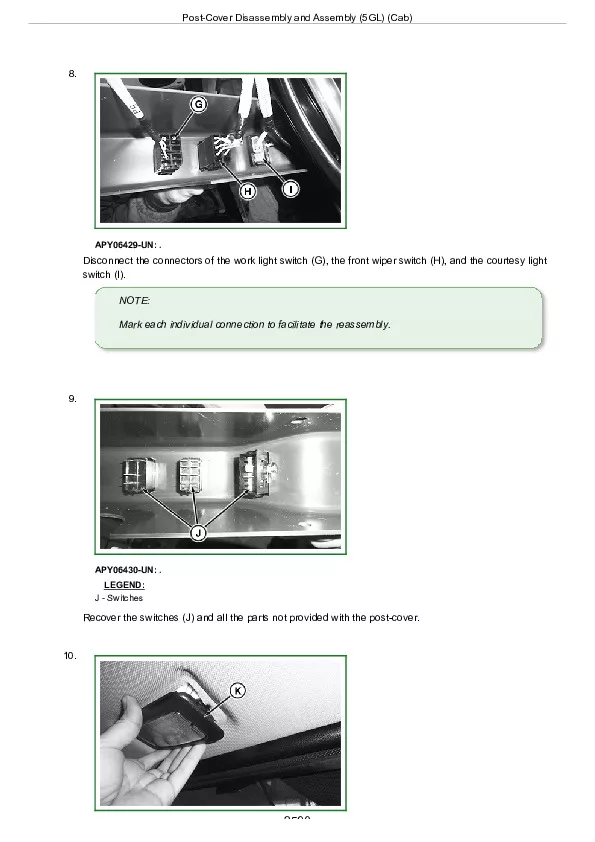
Post-Cover Disassembly and Assembly (5GL) (Cab)…………….2589
Remove and Install Recirculating/Fresh Air Filter (5GL) (Cab)…………….2592
Roof Headliner Disassembly and Assembly (5GL) (Cab)…………….2594
Group 30: Open Operator's Station…………….2298
Summary of References – Open Operator's Station…………….2599
Essential or Recommended Tools…………….2615
Remove and Install Roll-Bar (ROPS) (5G VNF)…………….2601
Remove and Install Roll-Bar (ROPS) (5GL)…………….2606
Group 35: Operator's Seat…………….2298
Summary of References – Operator's Seat…………….2614
Essential or Recommended Tools…………….2615
Remove and Install Operator’s Seat and Support…………….2616
Section 99: Special Tools…………….2618
Group 05: Special Tools (Dealer-Fabricated)…………….2618
Summary of References — Dealer-Manufactured Tools…………….2622
Adapter…………….2623
Cone Point Adjustment Tools…………….2624
Draft Control Adjusting Tool…………….2626
Seal Ring Replacement Kit – Tool 1…………….2627
Seal Ring Replacement Kit – Tool 2…………….2628
JDG716796…………….2629
Group 10: Special Tools (Available via SERVICEGUARD)…………….2618
Summary of References – Special Tools and Test Equipment…………….2632
D01019AA…………….2634
D01072AA…………….2635
D01210AA…………….2636
JDG1337…………….2637
JDG1375…………….2638
KJD10295…………….2639
KJD10301…………….2640
KJD10307…………….2641
KJD10392…………….2642
KJD10394…………….2643
KJD10395…………….2644
KJD10397…………….2645
KJD10432…………….2646
KJD10435…………….2647
KJD10436…………….2648
KJD10437…………….2649
KJD10438…………….2650
KJD10440…………….2651
KJD10442…………….2652
KJD10447…………….2653
KJD10451…………….2654
KJD10492…………….2655
KJD10493…………….2656
KJD10494…………….2657
KJD119034…………….2658
KJD119183…………….2659
KJD453795…………….2660
KJD474519…………….2661
KJD715093…………….2662
KJD715583…………….2663
KJD715668…………….2664
KJD715800…………….2665
KJD715801…………….2666
KJD715804…………….2667
KJD715805…………….2668
KJD715808…………….2669
KJD715810…………….2670
KJD715815…………….2671
KJD715821…………….2672
KJD715824…………….2673
KJD715825…………….2674
KJD715826…………….2675
KJD715827…………….2676
KJD715829…………….2677
KJD715830…………….2678
KJD715836…………….2679
KJD715838…………….2680
KJD715843…………….2681
KJD715844…………….2682
KJD715845…………….2683
KJD715848…………….2684
KJD715887…………….2685
KJD715888…………….2686
KJD716105…………….2687
KJD716106…………….2688
KJD716107…………….2689
KJD716108…………….2690
KJD716110…………….2691
KJD716111…………….2692
KJD716133…………….2693
KJD716134…………….2694
KJD716138…………….2695
KJD716139…………….2696
KJD716140…………….2697
KJD716143…………….2698
KJD716144…………….2699
KJD716156…………….2700
KJD716170…………….2701
KJD716171…………….2702
KJD716202…………….2703
KJD716211…………….2704
KJD716300…………….2705
KJD716302…………….2706
KJD716303…………….2707
KJD716304…………….2708
KJD716305…………….2709
FKM10475…………….2710
KJD10567…………….2711
KJD715082…………….2712
JDG10974EU…………….2713
KJD10571…………….2714
KJD10572…………….2715
KJD10574…………….2716
KJD10577…………….2717
7062A…………….2718
John Deere 5075GV, 5090GV, 5075GN, 5090GN, 5105GN, 5075GF, 5090GF, 5105GF, 5075GL, 5090GL and 5100GL (MY17- ) Tractors Repair Service Manual (TM410019)