Complete service technical manual with Electrical Wiring Diagrams for John Deere FPT F5D (DOC_DPF) Diesel Engines, with all the technical information to maintain, diagnose, repair, and rebuild like professional mechanics.
John Deere FPT F5D (DOC_DPF) Diesel Engines workshop service repair manual includes:
* Numbered table of contents easy to use so that you can find the information you need fast.
* Detailed sub-steps expand on repair procedure information
* Numbered instructions guide you through every repair procedure step by step.
* Troubleshooting and electrical service procedures are combined with detailed wiring diagrams for ease of use.
* Notes, cautions and warnings throughout each chapter pinpoint critical information.
* Bold figure number help you quickly match illustrations with instructions.
* Detailed illustrations, drawings and photos guide you through every procedure.
* Enlarged inset helps you identify and examine parts in detail.
ctm407919 – FPT F5D (DOC/DPF) Diesel Engines for John Deere Machines Component Technical Manual (EN).pdf
ctm407928 – FPT F5D (DOC/DPF) Moteur diesel French.pdf
ctm407929 – Dieselmotor FPT F5D (DOC/DPF) German.pdf
ctm407930 – Κινητήρας ντίζελ FPT F5D (DOC/DPF) Greek.pdf
ctm407939 – Motore diesel FPT F5D (DOC/DPF) Italian.pdf
ctm407953 – Silnik wysokoprężny FPT F5D (DOC/DPF) Polish.pdf
ctm407954 – Motor Diesel FPT F5D (DOC/DPF) Portuguese.pdf
ctm407980 – FPT F5D (DOC/DPF) Dizel Motor Turkish.pdf
PRODUCT DETAILS:
Total Pages: 545 pages
File Format: PDF (Internal Links, Bookmarked, Table of Contents, Searchable, Printable, high quality)
Language: English
TABLE OF CONTENTS
TABLE OF CONTENTS…………….1
Section 01: General Information…………….12
Group 000: Safety…………….12
Understand Signal Words…………….15
Avoid Heating Near Pressurized Fluid Lines…………….16
Avoid High-Pressure Fluids…………….17
Avoid Hot Exhaust…………….18
Avoid Static Electricity Risk When Refueling…………….19
Construct Dealer-Made Tools Safely…………….21
Decommissioning — Proper Recycling and Disposal of Fluids and Components…………….22
Exhaust Filter Cleaning…………….23
Follow Safety Instructions…………….24
Handle Fluids Safely—Avoid Fires…………….25
Handling Batteries Safely…………….26
Illuminate Work Area Safely…………….28
Install All Guards…………….29
Live With Safety…………….30
Practice Safe Maintenance…………….31
Precautions for Welding…………….33
Prepare for Emergencies…………….35
Prevent Acid Burns…………….36
Prevent Battery Explosions…………….38
Prevent Machine Runaway…………….39
Protect Against High Pressure Spray…………….40
Protect Against Noise…………….41
Recognize Safety Information…………….42
Remove Paint Before Welding or Heating…………….43
Replace Safety Signs…………….44
Service Cooling System Safely…………….45
Service Machines Safely…………….46
Stay Clear of Rotating Drivelines…………….47
Support Machine Properly…………….48
Use Proper Lifting Equipment…………….49
Use Proper Tools…………….50
Wait Before Opening High-Pressure Fuel System…………….382
Wear Protective Clothing…………….52
Work in Clean Area…………….53
Work In Ventilated Area…………….54
Group 001: Engine Identification Information…………….13
Engine Serial Number Plate Information – European Market…………….58
Engine Serial Number Plate Information – North American Market…………….61
Emissions Control System Certification Label – North American Market…………….63
Information Relative to Emissions Regulations…………….65
Group 002: Fuels, Lubricants, and Coolants…………….13
Diesel Engine Oil — Interim Tier 4, Final Tier 4, Stage IIIB, and Stage IV…………….68
Engine Oil and Filter Service Intervals — Interim Tier 4, Final Tier 4, Stage IIIB, and Stage IV…………….70
John Deere Break-In Plus™ Engine Oil — Interim Tier 4, Stage IIIB…………….71
Transmission and Hydraulic Oil…………….72
Front-Wheel Drive Axle Oil…………….73
Grease for Automated Lubrication Systems…………….75
Mixing of Lubricants…………….76
Lubricant Storage…………….77
Alternative and Synthetic Lubricants…………….78
Diesel Engine Coolant…………….79
Supplemental Coolant Additives…………….81
Operating in Warm Temperature Climates…………….82
Testing Diesel Engine Coolant…………….83
Storing Fuel…………….84
Handling and Storing Diesel Fuel…………….86
Diesel Fuel…………….86
Minimizing the Effect of Cold Weather on Diesel Engines…………….88
Lubricity of Diesel Fuel…………….90
Biodiesel Fuel…………….91
Testing Diesel Fuel…………….93
Oilscan™ and CoolScan™…………….94
Section 02: Repair and Adjustments…………….95
Group 010: Engine Rebuild…………….95
Summary of References – Engine Rebuild…………….100
Essential or Recommended Tools…………….343
Mount the Engine on Rotary Stand…………….102
Unloading the Engine from the Rotary Stand…………….104
Remove and Install Flywheel…………….106
Power Take-Off (PTO) for Service Air Compressor — Removal…………….109
Power Take-Off (PTO) for Service Air Compressor — Installation…………….110
Final Checks…………….112
Group 020: Cylinder Head and Valves Repair and Adjustment…………….95
Summary of References – Cylinder Head and Valves Repair and Adjustment…………….114
Essential or Recommended Tools…………….343
Cylinder Head — Removal and Installation…………….117
Cylinder Head Hydraulic Seal Check…………….128
Cylinder Head — Flatness Check…………….129
Rocker Assembly — Measurement…………….131
Tappet — Removal…………….132
Tappet — Installation…………….133
Tappet Measurement…………….134
Tappet Cover — Removal and Installation…………….135
Rocker Arm Push Rod — Inspection…………….141
Rocker Arm and Valve — Removal and Installation…………….149
Rocker Arm Shaft Assembly — Installation…………….147
Valve — Removal and Installation…………….149
Valve — Cleaning and Inspection…………….152
Valve — Measurement…………….153
Valve Stem and Valve Guide — Clearance Measurement…………….154
Valve Guide — Measurement…………….155
Valve Guide — Replacement…………….156
Valve Guide — Finishing…………….157
Valve Seat — Grinding and Replacement…………….158
Valve — Recess Measurement…………….160
Valve Spring — Inspection and Measurement…………….161
Glow Plug — Removal and Installation…………….162
Group 030: Cylinder Block, Liners, Pistons, and Rods Repair and Adjustment…………….96
Summary of References – Cylinder Block, Liners, Pistons, and Rods Repair and Adjustment…………….165
Essential or Recommended Tools…………….343
Connecting Rod — Specifications…………….167
Connecting Rod Small End Bushing — Inspection…………….168
Connecting Rod — Measurement…………….169
Connecting Rod and Half Bearings — Assembly…………….172
Pistons and Connecting Rods with Bearings — Removal…………….173
Piston and Connecting Rod — Assembly…………….174
Piston Liner Assembly — Installation…………….177
Piston Spray Jet — Removal…………….179
Piston Spray Jet — Installation…………….180
Piston Rings and Piston Pin — Removal…………….181
Piston Rings — Measurement…………….182
Piston Pin — Measurement…………….184
Piston Pin and Bore — Inspection…………….185
Piston Rings — Installation…………….187
Piston — Measurements…………….189
Piston Protrusion — Measurement…………….191
Cylinder Liner — Measurement…………….192
Cylinder Block — Flatness Check…………….194
Group 040: Crankshaft, Main Bearings, and Flywheel Repair and Adjustment…………….96
Summary of References – Crankshaft, Main Bearings, and Flywheel Repair and Adjustment…………….196
Essential or Recommended Tools…………….343
Crankshaft Pulley — Removal and Installation…………….198
Crankshaft Front Cover and Oil Seal — Installation…………….199
Crankshaft Rear Oil Seal — Removal and Installation…………….202
Crankshaft and Main Bearings — Removal…………….203
Connecting Rod Cap and Bearing Assembly Clearance — Measurement…………….205
Crankshaft — Measurement…………….209
Main Journal Bearing — Clearance Measurement…………….212
Crankshaft Thrust Clearance — Measurement…………….215
Crankshaft and Main Bearings — Installation…………….216
Balancer Shaft — Installation…………….218
Front Crankshaft Gear — Replacement…………….221
Flywheel Housing — Removal…………….222
Flywheel Housing — Installation…………….223
Engine Flywheel — Inspection…………….224
Group 050: Camshaft and Timing Gear Train Repair and Adjustment…………….97
Summary of References – Camshaft and Timing Gear Train Repair and Adjustment…………….226
Essential or Recommended Tools…………….343
Camshaft — Removal and Installation…………….228
Camshaft — Measurement…………….231
Camshaft Bushes — Inspection and Measurement…………….232
Camshaft Bushes — Replacement…………….234
Timing Gear Cover — Removal and Installation…………….235
Idle and Timing Gear — Removal and Installation…………….238
Engine Timing…………….240
Group 060: Lubrication System Repair and Adjustment…………….97
Summary of References – Lubrication System Repair and Adjustment…………….244
Essential or Recommended Tools…………….343
Engine Oil Filter — Removal and Installation…………….246
Engine Oil Heat Exchanger — Removal and Installation…………….248
Oil Pan — Removal and Installation…………….252
Oil Pump — Removal and Installation…………….254
Group 070: Cooling System Repair and Adjustment…………….97
Summary of References – Cooling System Repair and Adjustment…………….257
Essential or Recommended Tools…………….343
Drive Belt — Removal and Installation…………….259
Drive Belt — Inspection…………….262
Water Pump — Removal and Installation…………….263
Thermostat Housing — Removal and Installation…………….265
Group 080: Air Intake and Exhaust System Repair and Adjustment…………….97
Summary of References – Air Intake and Exhaust System Repair and Adjustment…………….270
Essential or Recommended Tools…………….343
Exhaust Manifold — Removal and Installation…………….272
Intake Manifold — Removal and Installation…………….277
Turbocharger — Removal and Installation…………….286
DOC/DPF Filter and Support — Removal and Installation…………….291
EGR — Removal and Installation…………….295
Engine Air Intake Elbow — Removal and Installation…………….299
Y510 – Turbocharger Wastegate Valve — Removal and Installation…………….301
Oil Vapor Recirculation (Blow-By) System — Removal and Installation…………….302
Group 090: Electronic Fuel System Repair and Adjustment…………….98
Summary of References – Electronic Fuel System Repair and Adjustment…………….306
Essential or Recommended Tools…………….343
Low-Pressure Fuel Lines — Removal and Installation…………….309
Fuel Filter and Prefilter — Removal and Installation…………….312
Fuel Line from High-Pressure Pump to Common Rail — Removal and Installation…………….327
Fuel Injection Pump — Removal and Installation…………….319
Common Rail — Removal and Installation…………….327
Common Rail, Pipes, and Combustible Filters…………….335
Injector — Removal and Installation…………….338
Group 110: Electrical Engine Control Repair and Adjustment…………….98
Summary of References – Electrical Engine Control Repair and Adjustment…………….342
Essential or Recommended Tools…………….343
A500 – Engine Control Unit — Removal and Installation…………….344
G02 – Alternator — Removal and Installation…………….346
Alternator Support — Removal and Installation…………….348
Engine Wiring Harness — Removal and Installation…………….350
Section 03: Theory of Operation…………….352
Group 123: Cooling System…………….352
Engine Cooling System…………….358
Group 126: Lubrication System…………….352
Engine Lubrication System…………….367
Group 127: Fuel Supply System…………….352
Fuel Supply System Operation…………….375
Supply Pump…………….378
High-Pressure Fuel System…………….382
Low-Pressure Fuel System…………….383
Low-Pressure Fuel System — Pipe Layout…………….384
Low-Pressure Circuit Pressure Measure Point…………….387
Fuel Filter Operation…………….393
Fuel Injection System Overview…………….394
Injector Calibration Code…………….395
Fuel Rail Pressure Relief Valve (PRV)…………….396
Group 128: Oil Vapor Recirculation System…………….352
Engine Oil Vapor Recirculation…………….399
Group 130: Electronic Fuel System…………….352
G01 — Alternator…………….403
Electronic Injectors…………….405
R501, R502, R503, R504 — Glow Plugs…………….407
A510 — Glow Plug Control Unit…………….408
R505 — Fuel Filter Heater…………….410
B500 — Coolant Temperature Sensor…………….411
B503 — Fuel Temperature Sensor…………….412
B505 — Engine Oil Pressure Sensor…………….413
B506 — Fuel Rail Pressure Sensor…………….414
B507 — Exhaust Gas Temperature Sensor…………….415
B509 — Ambient Air Temperature Sensor…………….416
Air Temperature and Boost Pressure Sensor…………….417
Absolute Exhaust Gas Pressure Sensor…………….418
Camshaft Timing Sensor — Segmental Speed…………….420
Crankshaft Speed Sensor — Incremental Speed…………….421
A530 — Air Throttle Actuator…………….423
High-Pressure Fuel Pump Dosing Unit…………….424
Air Pressure Regulator Valve for Wastegate Actuator…………….426
Y530 — Exhaust Gas Recirculation Valve…………….427
After-treatment System — Sensors and Electronic Components…………….428
DEF Module Connector…………….430
Ammonia (NH3) Sensor Control Unit…………….431
B514 – After-treatment Outlet NH3 Sensor…………….433
B515, B516 — NOx Sensor…………….434
Group 135: Air Intake and Exhaust System…………….353
Turbocharger System…………….438
EGR Exhaust Gas Recycle System…………….440
EGR – Exhaust Cooling System…………….442
3-way Valve…………….444
After Treatment System (ATS)…………….445
ATS system components…………….449
Removal of the DOC-DPF Module…………….450
Assembly of the DOC-DPF Module…………….452
Assembly of the DPF with DOC Module…………….454
Group 138: Electronic Control Unit…………….353
Engine Control Unit…………….457
ECU System Operation…………….458
A500 — Engine Control Unit (ECM) for Engine F5D (DOC/DPF)…………….462
Section 04: Diagnostics…………….466
Group 160: Diagnostic Instructions and Information…………….466
Engine Diagnostic Instructions and Information…………….468
Section 05: Tools…………….469
Group 170: Special Tools…………….469
Summary of References – Special Tools…………….471
JDG99322205…………….472
JDG99361043…………….473
JDG99346259…………….474
JDG99346264…………….475
JDG99396039…………….476
99360076…………….477
99360091…………….478
99360183…………….479
99360268…………….480
JDG99360288…………….481
JDG99360292…………….482
JDG99360362…………….483
JDG99370006…………….484
99360605…………….485
99360616…………….486
JDG99360612…………….487
99390310…………….488
JDG99395216…………….489
99395603…………….490
99395849…………….491
99317915…………….492
JDG99370415…………….493
99389829…………….494
99305455…………….495
SP2275…………….496
Section 06: Specifications…………….497
Group 190: Repair and Diagnostic Specifications…………….497
Metric Bolt and Screw Torque Values…………….500
Unified Inch Bolt and Screw Torque Values…………….502
Engine Views…………….504
Main Engine Specifications…………….509
Group 020 — Cylinder Head Specifications…………….511
Cylinder Head Technical Specifications…………….512
Group 030 — Cylinder Block, Pistons, and Connecting Rods Specifications…………….514
Cylinder Block, Pistons, and Connecting Rods Technical Specifications…………….515
Group 040 — Crankshaft, Main Bearings, and Flywheel Specifications…………….517
Crankshaft, Main Bearings, and Flywheel Technical Specifications…………….518
Group 050 — Timing Gear Specifications…………….520
Timing Technical Specifications…………….521
Group 060 — Lubrication System Specifications…………….522
Group 070 — Cooling System Specifications…………….523
Group 080 — Air Intake and Exhaust System Specifications…………….524
Group 090 — Electronic Fuel System Specifications…………….526
Electronic Fuel System Technical Specifications…………….528
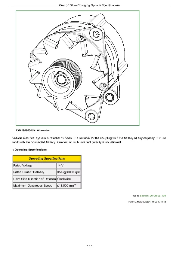
Group 100 — Charging System Specifications…………….529
Group 110 — Electrical Engine Control Specifications…………….531
Group 115 — Aftertreatment Device Specifications…………….543
John Deere FPT F5D (DOC_DPF) Diesel Engines Component Technical Manual (CTM407919)