Complete Component Technical Manual with Electrical Wiring Diagrams for John Deere PowerTech 9.0 L OEM Diesel Engines Base Engine Repair – (Worldwide Edition), with all the technical information to maintain, diagnose, repair, and rebuild like professional mechanics.
John Deere PowerTech 9.0 L OEM Diesel Engines Base Engine Repair – (Worldwide Edition) workshop service repair manual includes:
* Numbered table of contents easy to use so that you can find the information you need fast.
* Detailed sub-steps expand on repair procedure information
* Numbered instructions guide you through every repair procedure step by step.
* Troubleshooting and electrical service procedures are combined with detailed wiring diagrams for ease of use.
* Notes, cautions and warnings throughout each chapter pinpoint critical information.
* Bold figure number help you quickly match illustrations with instructions.
* Detailed illustrations, drawings and photos guide you through every procedure.
* Enlarged inset helps you identify and examine parts in detail.
ctm400 – PowerTechTM 9.0 L OEM Diesel Engines Base Engine Repair – (Worldwide Edition) Component Technical Manual.pdf
ctm401 – Motores diesel OEM PowerTech de 9.0 l Reparación del motor básico – (Edición mundial) Technical Manual.pdf
ctm402 – Moteurs diesel OEM PowerTech 9,0 l Remise en état des moteurs standard -: (Édition mondiale) Technical Manual.pdf
ctm403 – PowerTech 9,0-l-OEM-Dieselmotoren Reparatur des Grundmotors -: (Weltweite Ausgabe) Technical Manual.pdf
ctm404 – Motori diesel OEM PowerTech da 9,0 l Riparazione motore base -: (Edizione universale) Technical Manual.pdf
ctm407 – Дизельные двигатели OEM PowerTech объемом 9,0 л Ремонт основного двигателя -: (Исполнение для всех стран) Technical Manual.pdf
ctm408 – Motores Diesel OEM PowerTech 9,0 L Reparo do Motor Base -: (Edição Mundial) Technical Manual.pdf
ctm410 – PowerTech 9.0 升 OEM 柴油发动机 基本发动机 -: (世界通用机型) 维修技术手册.pdf
CTM400 (29AUG11) – PowerTech 9.0 L OEM Diesel Engines Base Engine Component Technical Manual.pdf
PRODUCT DETAILS:
Total Pages: 1,012 pages
File Format: PDF/EPUB/MOBI/AZW (PC/Mac/Android/Kindle/iPhone/iPad; bookmarked, ToC, Searchable, Printable)
Language: English
ctm400 – PowerTech™ 9.0 L OEM Diesel Engines Base Engine Repair -: (Worldwide Edition)
Component Technical Manual
Table of Contents
Foreword
About this Manual
Identification Views – 6090 Tier 3 / Stage IIIA Emissions Certified Engines
Section 01: General
Group 000: Safety
Recognize Safety Information
Understand Signal Words
Follow Safety Instructions
Replace Safety Signs
California Proposition 65 Warning
Illuminate Work Area Safely
Work in Clean Area
Use Proper Tools
Live With Safety
Prevent Machine Runaway
Handle Fuel Safely—Avoid Fires
Prepare for Emergencies
Handle Starting Fluid Safely
In Case of Fire
Handle Fluids Safely—Avoid Fires
Avoid Static Electricity Risk When Refueling
Service Machines Safely
Wear Protective Clothing
Protect Against Noise
Handling Batteries Safely
Prevent Acid Burns
Stay Clear of Rotating Drivelines
Install All Guards
Practice Safe Maintenance
Remove Paint Before Welding or Heating
Avoid Heating Near Pressurized Fluid Lines
Avoid High-Pressure Fluids
Do Not Open High-Pressure Fuel System
Protect Against High Pressure Spray
Prevent Battery Explosions
Avoid Hot Exhaust
Work In Ventilated Area
Service Cooling System Safely
Decommissioning — Proper Recycling and Disposal of Fluids and Components
Group 001: Engine Identification
Engine Model Designation
Engine Serial Number Plate Information
OEM Engine Option Code Label
Group 002: Fuels, Lubricants and Coolant
Diesel Fuel
Supplemental Diesel Fuel Additives
Lubricity of Diesel Fuel
Handling and Storing Diesel Fuel
BioDiesel Fuel
Testing Diesel Fuel
Fuel Filters
Minimizing the Effect of Cold Weather on Diesel Engines
Diesel Engine Break-In Oil — Non-Emissions Certified and Certified Tier 1, Tier 2, Tier 3, Stage I, Stage II, and Stage III
Engine Oil and Filter Service Intervals
Diesel Engine Oil — Tier 3 and Stage III
Mixing of Lubricants
Alternative and Synthetic Lubricants
Lubricant Storage
Oil Filters
Grease
Diesel Engine Coolant (engine with wet sleeve cylinder liners)
Water Quality for Mixing with Coolant Concentrate
Operating in Warm Temperature Climates
Testing Coolant Freeze Point
Disposing of Coolant
Section 02: Repair and Adjustments
Group 010: Engine Rebuild
Engine Overhaul Guidelines
Engine Repair Stand
Safety Precautions
Install Adapters on Engine Repair Stand
Install Engine Lift Straps
Engine Lifting Procedure
Clean Engine
Disconnect Turbocharger Oil Inlet Line
Mount Engine on Repair Stand
Engine Disassembly Sequence for Overhaul
Sealant Application Guidelines
Engine Assembly Sequence After Overhaul
Engine Break-In Guidelines
Perform Engine Break-In
Check Crankcase Ventilation System
Check Air Intake System
Check Exhaust System
Check and Service Cooling System
Check Electrical System
General Tune-Up Recommendations
Group 021: Cylinder Head and Valves Repair and Adjustment
Valve — Clearance Adjustment
Valve — Lift Check
Cylinder Head — Removal
Cylinder Head—Preparation and Measurement
Diagnosing Head Gasket Joint Failures
Head Gasket Diagnostic Charts
Head Gasket Inspection and Repair Sequence
Rocker Arm Assembly — Inspection
Rocker Arm Shaft Assembly — Removal and Tear Down
Valve — Recess Measurement
Preliminary Cylinder Head and Valve Checks
Valve — Assembly Removal
Valve Springs — Inspection
Valve Retainer, Valve Bridges, and Valve Retainer Locks — Inspection
Valve — Cleaning and Inspection
Valve — Measurement
Valve — Grinding
Cylinder Head — Cleaning and Inspection
Cylinder Head — Flatness Check
Cylinder Head — Thickness Measurement
Fuel Injector Sleeves — Remove
Fuel Injector Sleeves — Install
Valve Guide — Cleaning
Valve Guide — Measurement
Valve Guides — Removal
Valve Guides — Installation
Valve Seat — Cleaning and Inspection
Valve Seat — Recess Measurement
Valve Seat — Grinding
Valve Seat Inserts — Removal
Valve Seat Inserts — Installation
Cylinder Head Nozzle Bore — Cleaning and Inspection
Push Rod — Cleaning and Inspection
Cylinder Block Top Deck — Cleaning and Inspection
Valve Assembly — Reassemble
Cylinder Head — Installation
Cylinder Head Cap Screw Torque Procedure
Rocker Arm Shaft Assembly — Assemble
Rocker Arm Assembly — Installation
Rocker Arm Cover Vent hose — Inspection
Final Assembly — Fuel Pump Side of Engine
Final Assembly — Exhaust Manifold Side of Engine
Perform Engine Break— In
Group 030: Cylinder Block, Liners, Pistons, and Rods Repair and Adjustment
Preliminary Liner, Piston, and Rod Checks
Remove Pistons and Connecting Rod Assemblies
Cylinder Liner — Standout Measurement
Remove Cylinder Liners
Deglaze Cylinder Liners
Cylinder Liner — Cleaning
Piston and Connection Rod Assembly — Tear Down
Piston Ring — Removal
Clean Pistons
Visually Inspect Pistons
Inspect Piston Pin and Bore
Visually Inspect Cylinder Liners
Cylinder Liner Manufacturing Date Code Explanation
Piston to Liner — Clearance Check
Inspect Rod and Cap
Piston Pin and Bushing — Inspection
Piston Pin Bushing and Pin Bore — Removal
Measure Liner Flange
Inspect and Measure Connecting Rod Bearings
Piston Pin Bushing — Installation
Complete Disassembly of Cylinder Block (If Required)
Piston Cooling Orifices — Removal
Clean Cylinder Block
Measure Cylinder Block
Cylinder Block — Inspect and Reclaim
Piston Cooling Orifices — Installation
Install Packing on Cylinder Liner and O-Rings in Block
Install Cylinder Liner in Block
Piston Ring — Installation
Install Piston and Connecting Rod
Connecting Rod Cap Screw — Torque Procedure
Check Engine Rotation for Excessive Tightness
Complete Final Assembly
Group 040: Crankshaft, Main Bearings and Flywheel Repair and Adjustment
Crankshaft and Main Bearing Failure Analysis
Inspect Vibration Damper
Check Crankshaft End Play
Remove Crankshaft Vibration Damper (Straight Nose Crankshaft)
Remove Crankshaft Vibration Damper and Hub (Tapered Nose Crankshaft)
Crankshaft Dual Damper — Removal
Remove Crankshaft Front Oil Seal and Wear Sleeve (Straight Nose Crankshaft)
Remove Crankshaft Front Unitized Oil Seal (Tapered Nose Crankshaft)
Remove Timing Gear Cover—Engine Removed
Inspect and Measure Flywheel
Check Flywheel Housing Face Runout
Check Flywheel Face Flatness
Check Pilot Bearing Bore Concentricity
Remove Flywheel
Remove Flywheel (Tapered Nose Crankshaft)
Crankshaft Unitized Rear Oil Seal — Removal (Straight Nose Crankshaft)
Remove SAE 1 Flywheel Housing
Remove SAE 2 and 3 Flywheel Housing
Replace Flywheel Ring Gear
Remove Rear Oil Seal Housing—Engine Removed
Remove Main Bearing Caps
Check Main Bearing Oil Clearance
Remove Connecting Rod Caps and Remove Crankshaft
Crankshaft — Inspection
Measure Assembled I.D. of Bearings and O.D. of Crankshaft Journals
Main Bearing Cap Line Bore Specifications
Thrust Bearing New Part Specifications
Replace (Crankshaft) Oil Pump Drive Gear
Replace Crankshaft Gear
Inspect Thrust Bearings
Install Main Bearings and Crankshaft
Check Crankshaft Rear Oil Seal Housing Runout
Install Crankshaft Front Unitized Oil Seal (Straight Nose Crankshaft)
Install Crankshaft Front Unitized Oil Seal (Tapered Nose Crankshaft)
Install Vibration Damper (Straight Nose Crankshaft)
Install Vibration Damper and Hub (Tapered Nose Crankshaft)
Crankshaft Dual Damper — Installation (Tapered Nose Crankshaft)
Install Crankshaft Rear Oil Seal Housing
Crankshaft Rear Oil Seal Assembly Handling Precautions
Install Crankshaft Rear Unitized Oil Seal (Straight Nose Crankshaft)
Install Crankshaft Rear Unitized Oil Seal (Tapered Nose Crankshaft)
Install SAE 2 and 3 Flywheel Housing
Install Flywheel
Install Flywheel (Tapered Nose Crankshaft)
Install SAE 1 Flywheel Housing
Complete Final Assembly
Group 050: Camshaft and Timing Gear Train Repair and Adjustment
Check Camshaft End Play and Measure Gear Backlash
Remove Vibration Damper and Timing Gear Cover
Remove, Inspect, and Install Crankshaft Gear-Driven Auxiliary Drive — If Equipped
Remove Camshaft
Remove Camshaft Gears
Measure Thrust Washer Thickness
Inspect and Measure Camshaft Followers
Visually Inspect Camshaft
Measure Camshaft Journal O.D. and Bushing I.D.
Measure Camshaft Lobe Lift
Camshaft Gears — Installation
Service Camshaft Bushings Using JDG602 Adapter Set
Service Camshaft Bushings Using JDG606 Adapter Set
Camshaft Roller Followers — Install
Install Camshaft
Install Thrust Washer and Timing Gear Cover
Complete Final Assembly
Group 060: Lubrication System Repair and Adjustment
Diagnosing Lubrication System Malfunctions
Dipstick Tube and Dipstick — Installation
Dipstick Tube and Dipstick — Removal
Top-Load Oil Filter Assembly
Top Load Oil Filter – Theory of Operation
Install Oil Filter Assembly
Changing Top-Load Oil Filter
Oil Pressure Regulating Valve — Removal
Oil Pressure Regulating Valve — Installation
Engine Oil Cooler Assembly
Remove, Inspect, and Install Engine Oil Cooler
Remove Engine from Tractors for Access to Engine Oil Pump
Remove Oil Pan
Check Crankshaft Gear-to-Oil Pump Drive Gear Backlash
Remove Engine Oil Pump
Inspect and Clean Oil Pump
Check Drive Shaft End Play
Check Drive Shaft Side Movement
Check Pumping Gear Backlash
Inspect Oil Pump Drive Gear
Install Engine Oil Pump
Install Oil Bypass & Oil Pump Tubes & Oil Pump Adapter
Remove, Inspect, and Install Oil Pump Pickup Tube
Install Engine Oil Pan
Tighten Cap Screws on Front Frame/Oil Sump – Tractors
Group 070: Cooling System Repair and Adjustment
Inspect Fan Hub & Replace Bearings in Heavy-Duty, Adjustable Fan Drive Assembly
Replace Bearings in Coolant Manifold-Mounted, Fixed Fan Drive Assembly
Fan Drive Assembly
Checking Belt Tensioner Spring Tension and Belt Wear
Inspect and Install Fan Assembly
Visually Inspect Coolant Pump
Remove Coolant Pump Assembly
Install Coolant Pump Assembly
Replace Bypass Tube & O-Rings in Thermostat Housing
Remove and Test Thermostats
Remove Thermostat Housing
Install Thermostats
Install Thermostat Housing
Remove and Install Coolant Temperature Sensor
Servicing of Engine Coolant Heater
Remove Heat Exchanger or Top Tank (Marine)
Install Heat Exchanger or Top Tank (Marine)
Bleed Air from Coolant System
Complete Final Assembly
Group 080: Air Intake and Exhaust System Repair and Adjustment
Extending Turbocharger Life
Remove Turbocharger
Remove Turbocharger Oil Drain Line
Remove Turbocharger Oil Supply Line
Turbocharger — Failure Analysis
Turbocharger Inspection
Perform Radial Bearing Clearance Test
Repair Turbocharger
Prelube Turbocharger
Install Turbocharger
Turbocharger Break-In
Recommendations for Turbocharger Use
Install Turbocharger Oil Supply Line Brackets
Install Turbocharger Oil Supply Line
Install Turbocharger Oil Drain Line
Install Heat Shield & Turbocharger Oil Supply Line Bracket
Remove and Install Turbocharger Actuator
Install Actuator Coolant Line Fittings
Install Turbocharger Actuator Coolant Return Line
Install Turbocharger Actuator Coolant Supply Line
Install Actuator Coolant Supply Line – Tractors
Remove and Install Actuator Linkage
Remove and Install Turbocharger Actuator Linkage – Ball Type
Remove Exhaust Gas Recirculator (EGR) Assembly
Remove & Install EGR Valve
Remove and Install EGR Coolant Manifold
Remove and Install EGR Cooler Supply Line
Remove and Install EGR Cooler Return Line
Remove, Inspect, and Install Exhaust Manifold
Remove, Inspect, and Install Intake Manifold
Install EGR
Remove and Install Air Inlet/Heater
Group 081: PowerTech E Air Intake and Exhaust System Repair and Adjustment
Turbocharger — Extending Life
Turbocharger — Remove Oil Drain Line
Turbocharger — Install Oil Drain Line
Turbocharger — Remove
Turbocharger — Install
Exhaust Manifold — Remove
Exhaust Manifold — Install
Air Intake Assembly — Removal
Air Intake Assembly — Install
Group 082: Marine Engines Air Intake and Exhaust System Repair
Intake Manifold (Marine) – Removal
Intake Manifold (Marine) – Installation
Charge Air Cooler (Marine) — Removal
Charge Air Cooler (Marine) — Installation
Exhaust Manifold (Marine) — Removal
Exhaust Manifold (Marine) — Installation
Turbocharger (Marine) — Removal
Turbocharger (Marine) — Installation
Group 100: OEM Starting and Charging Systems Repair and Adjustment
Remove and Install Alternator (OEM Engines)
Remove and Install Starter Motor (OEM Engines)
Section 03: Theory of Operation
Group 120: Base Engine Operation
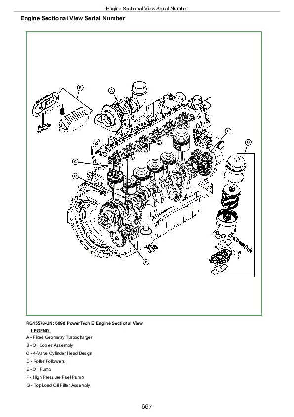
Engine Sectional View Serial Number
General Engine Operation
Lubrication System Operation
Cooling System Operation
Exhaust Gas Recirculator (EGR) and Variable Geometry Turbocharger (VGT)
Head Gasket Joint Construction and Operation
Air Intake and Exhaust System Operation
Turbocharger Operation
How the Turbocharger is Lubricated
Group 121: PowerTech E Base Engine Operation
Engine Sectional View Serial Number
General Engine Operation
Lubrication System Operation
Cooling System Operation
Air Intake and Exhaust System Operation
Turbocharger Operation
How the Turbocharger is Lubricated
Head Gasket Joint Construction and Operation
Section 04: Diagnostics
Group 150: Observable Diagnostics and Tests
About This Group of the Manual
9.0L – L1 -Excessive Oil Consumption
Engine Oil Consumption
9.0L – L2 – Engine Oil Pressure Low
9.0L – L2 – Engine Oil Pressure Low
9.0L – L3 – Engine Oil Pressure High
9.0L – L4 – Soot or Sludge in the Oil
9.0 L – C1 – Engine Coolant Temperature Above Normal
9.0L – C2 – Engine Coolant Temperature Below Normal
9.0L – C3 – Coolant In Oil or Oil In Coolant
9.0L – C4 – Coolant Leaking from Weep Hole
Test Engine Compression Pressure with Mechanical Gauge
Check Engine Cranking Speed
Check Engine Oil Pressure
Check for Excessive Engine Crankcase Pressure (Blow-By) (Base Pressure)
Excessive Fuel Filter Replacement
Check for Turbocharger Oil Seal Leak
Inspect Thermostat and Test Opening Temperature
Cooling System Pressure Test
EGR Cooler Test
Engine Coolant Leakage Diagnostic Procedure (After Engine Rebuild)
Intake Manifold Leakage Diagnostic
Charge Air System Diagnostic
Charge Air Cooler Test
Check for Head Gasket Failures
Measure Intake Manifold Pressure (Turbo Boost)
Check for Intake and Exhaust Restrictions
Check for Exhaust Air Leaks
Excessive Engine Vibration
Section 05: Tools and Other Materials
Group 170: Special Tools
205466
75240
D01062AA
D01168AA
D01207AA
D01209AA
D01299AA
D01251AA
D01300AA
D05012ST-A
D05104ST
D05223ST
D17006BR
D17015BR
D17024BR
D17030BR
D17525CI
D17526CI
D17527CI
DFRG3
DFRG9
DFRG11
JDE6
JDE93
JDE98A
JDE138
JDE41296
JDG22
JDG23
JDG337
JDG405
JDG451
JDG476(85)
JDG477(85)
JDG478
JDG602
JDG606
JDG681A
JDG721
JDG782A
JDG820
JDG839
JDG1020
JDG1069
JDG1145
JDG1571
JDG1649A
JDG1948
JDG1953
JDG1954
JDG1962
JDG1963
JDG2046
JDG2047A
JDG2047AP1
JDG10040
JDG10057
JDG10059A
JDG10194
JDG10254
JDG10539A
JDG10544
JDG10545
JDG10549
JDG10631
JDG10854
JDG10942
JDG10993
JDG10994
JDG10996
JDG10997
JDG10998
JDG10999
JDG11004A
JDG11055
JDG11056
JDG11083
JDG11253
JDG11263
JDG11334
JDG11864
JDH7
JT01674A
JT05536
JT05697A
Group 180: Lubricants, Sealants, and Other Materials
Group 021 — Cylinder Head and Valves – Other Materials
Group 030 — Cylinder Block, Liners, Pistons, and Rods Other Materials
Group 040 — Crankshaft, Main Bearings and Flywheel Other Materials
Group 050 — Camshaft and Timing Gear Train Other Materials
Group 060 — Lubrication System Other Materials
Group 070 — Cooling System Other Materials
Group 080 — Air Intake and Exhaust System Other Materials
Section 06: Specifications
Group 200: Repair and General OEM Specifications
General OEM Engine Specifications
Unified Inch Bolt and Screw Torque Values
Metric Bolt and Screw Torque Values
Group 020 — Cylinder Head and Valves Repair Specifications
Group 030 — Cylinder Block, Liners, Pistons and Rods Repair Specifications
Group 040 — Crankshaft, Main Bearings and Flywheel Repair Specifications
Group 050 — Camshaft and Timing Gear Train Repair Specifications
Group 060 — Lubrication System Repair Specifications
Group 070 — Cooling System Repair Specifications
Group 080 — Air Intake and Exhaust System Repair Specifications — PowerTech PSX
Group 081 — Air Intake and Exhaust System Repair Specifications — PowerTech PVX
OEM Starting and Charging Systems
Group 210: Diagnostic Specifications
Base Engine Diagnostic Specifications (Includes Dynamometer Specifications (OEM) and Turbocharger Boost Specifications)
Dynamometer Test Specifications
Intake Manifold Pressure (Turbocharger Boost) Specifications
Effects of Altitude and Temperature on Engine Performance
John Deere PowerTech 9.0 L OEM Diesel Engines Base Engine Repair Component Technical Manual (CTM400)