John Deere Tractors 5080G, 5090G, 5090GH, 5080GV, 5090GV, 5100GV, 5080GF, 5090GF, 5100GF Repair Service Manual (TM402519)
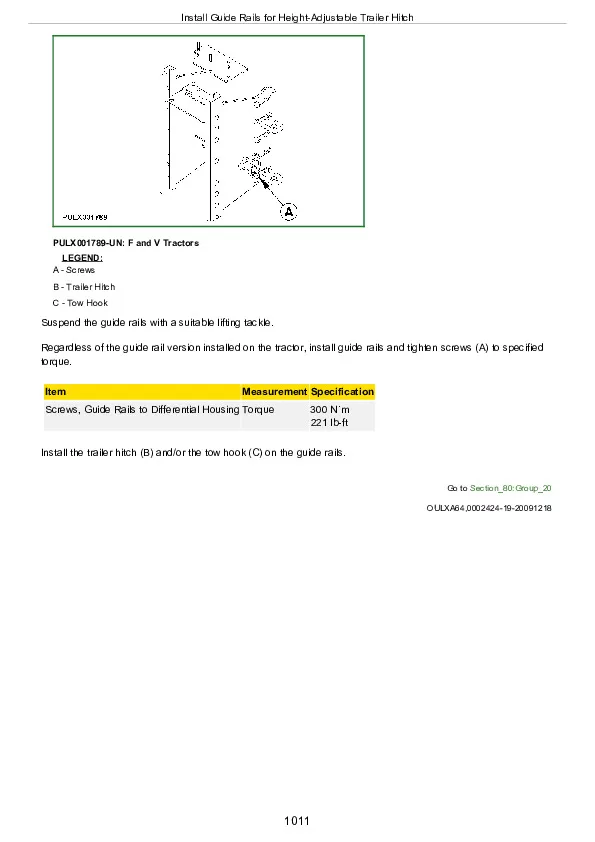
Complete service repair manual for John Deere Tractors 5080G, 5090G, 5090GH, 5080GV, 5090GV, 5100GV, 5080GF, 5090GF, 5100GF (Worldwide), with all the technical information to maintain, diagnose, repair, and rebuild like professional mechanics.
John Deere Tractors 5080G, 5090G, 5090GH, 5080GV, 5090GV, 5100GV, 5080GF, 5090GF, 5100GF workshop service repair manual includes:
* Numbered table of contents easy to use so that you can find the information you need fast.
* Detailed sub-steps expand on repair procedure information
* Numbered instructions guide you through every repair procedure step by step.
* Notes, cautions and warnings throughout each chapter pinpoint critical information.
* Bold figure number help you quickly match illustrations with instructions.
* Detailed illustrations, drawings and photos guide you through every procedure.
* Enlarged inset helps you identify and examine parts in detail.
TM402519 – John Deere Tractors 5080G, 5080GF, 5080GV, 5090GH, 5100GF, 5100GV, 5090G, 5090GV, 5090GF Technical Manual (Repair).PDF
Total Pages: 1,363 pages
File Format: PDF (bookmarked, ToC, Searchable, Printable, high quality)
Language: English
MAIN SECTIONS
Foreword
Safety
Safety Measures
General Information
Specifications
Tune-Up
Predelivery Inspection
Engine
Removal and Installation of Engine Components
Fuel and Air Intake Systems
Speed Control Linkage
Fuel System
Air Intake System
Electrical System
Battery, Starter Motor, and Alternator
Switches and Sensors
Transmission
Removal and Installation of Power Train Components
Clutch
Hi-Lo Clutch (24/24-Speed Transmission)
Transmission
24/12-Speed Transmission
Removal and Installation of Components – 24/12-Speed Transmission
Electro-Hydraulic Forward High/Low and Reverse Clutch – 24/12-Speed Transmission
Drive Systems
Component Removal and Installation
Front-Wheel Drive Clutch – Transmission
Differential
Final Drives
Power Take-Off
Transmission Housing – Sensors
Steering and Brake Systems
Steering System
Brake System
Hydraulic System
Hydraulic Pump and Filter
Hitch
Three-Point Hitch
Selective Control Valves
Miscellaneous
Removal and Installation of Components
Front Axle
Front and Rear Wheels
Trailer Mounting and Swinging Drawbar
Fenders
Operator’s Cab and Open Operator’s Station
Remove and Install Operator’s Cab/Open Operator’s Station
Controls and Instruments
Air-Conditioning System
Heating System
Operator’s Cab
Open Operator’s Station
Operator’s Seat
Special Tools
Special Tools (Dealer-Fabricated)
Special Tools (Available as Spare Parts)
tm402519 – 5080G-5090G, 5090GH,5080GV-5100GV and5080GF-5100GF TractorsRepair
Table of Contents
Foreword
Section 05: Safety
Group 05: Safety Measures
Recognize Safety Information
Understand Signal Words
“Important” – Information
”Note” Information
Follow Safety Instructions
Handle Fluids Safely—Avoid Fires
Prevent Battery Explosions
Prepare for Emergencies
Prevent Acid Burns
Service Cooling System Safely
Avoid High-Pressure Fluids
Park Machine Safely
Support Machine Properly
Wear Protective Clothing
Work in Clean Area
Service Machines Safely
Work In Ventilated Area
Illuminate Work Area Safely
Replace Safety Signs
Use Proper Lifting Equipment
Keep ROPS Installed Properly
Service Tires Safely
Avoid Harmful Asbestos Dust
Avoid Heating Near Pressurized Fluid Lines
Remove Paint Before Welding or Heating
Use Proper Tools
Dispose of Waste Properly
Use Safety Lights and Devices
Practice Safe Maintenance
Service Front-Wheel Drive Tractor Safely
Live With Safety
Section 10: General Information
Group 05: Specifications
Summary of References – Specifications
Engine
Transmission
Front-Wheel Drive Clutch
Hydraulic System
Electrical System
Capacities
Sound Level
Fuel System
Brakes
Three-Point Hitch
Loads and Weights
Towable Loads
Shipping Weights
Maximum Permissible Axle Loads and Total Weights
Load Capacity of Tires
Load Capacity of Tires With Front Loader
Observe Rear Wheel Tread Width Limitations
Metric Bolt and Screw Torque Values
Unified Inch Bolt and Screw Torque Values
Diesel Fuel
Handling and Storing Diesel Fuel
Do Not Use Galvanized Containers
Fill Fuel Tank
Diesel Engine Break-In Oil
Diesel Engine Oil
Transmission and Hydraulic Oil
Front-Wheel Drive Axle and Rear Drop Axle Oil
Grease
Oil Filters
Lubricant Storage
Mixing of Lubricants
Diesel Engine Coolant
Operating in Warm Temperature Climates
Alternative and Synthetic Lubricants
Serial Number Plates
Product Identification Number Location
Engine Serial Number
Fuel Injection Pump Serial Number Location
Power Steering Valve Serial Number Location
Air-Conditioning Compressor Serial Number Location
Transmission Serial Number Location
Front Axle (2WD) Serial Number Location
Front-Wheel Drive Serial Number
Group 10: Tune-Up
Summary of References – Tune-Up
Using High-Pressure Washers
Preliminary engine test
Clean Radiator and Oil Cooler
Clean Air-Conditioning System Condenser
Check Hoses and Hose Clamps
Clean Engine Crankcase Vent Tube
Clean the Dust Unloading Valve
Engine Air Filter
Cleaning the Primary Filter Element
Cleaning a Dusty Element
Secondary (Safety) Element
Clean Cab Air Filters
Check Belt Wear and Tension
Check Engine Oil Level
Check Brake System Oil Level
Check Coolant Level
Check Transmission/Hydraulic System Oil Level
Check the Fuel Filter
Bleed Fuel System
Adjust Hand Throttle
Starting Motor
Battery – Checking Specific Gravity
Check Neutral Start System
Check Setting of Head Lights and Work Lights
Check Lights
Final Engine Check
Tractor Operation Check
Group 15: Predelivery Inspection
Predelivery Inspection
Section 20: Engine
Group 00: Removal and Installation of Engine Components
Summary of References – Remove and Install Engine Components
Engine Repair
Specifications
Remove Engine
Install Engine
Water Pump Repair
Remove and Inspect Radiator
Install Radiator
Remove, Inspect and Install Charge Air Cooler and Oil Cooler
Replace Thermostat
Section 30: Fuel and Air Intake Systems
Group 05: Speed Control Linkage
Summary of References – Speed Control Linkage
Adjust Hand Throttle Lever and Accelerator Pedal
Recondition Hand Throttle Lever and Accelerator Pedal
Group 10: Fuel System
Fuel System – Summary of References
Injection Pump, Nozzle and Governor Repair
Drain Fuel Tank
Remove, Inspect and Install Fuel Tank (Standard Tractors)
Remove, Inspect and Install Fuel Tank (F and V Tractors)
Remove, Inspect and Install Fuel Tank Protection
Replace Fuel Filter
Remove and Install Fuel Filter Assembly
Replace Fuel Transfer Pump
Bleed Fuel System
Group 15: Air Intake System
Summary of References – Air Intake System
Turbocharger Repair
Remove and Install the Air Cleaner Element
Remove and Install Air Intake Hoses
Section 40: Electrical System
Group 05: Battery, Starter Motor, and Alternator
Battery, Starter Motor and Alternator – Summary of References
Starting Motor Repair
Disconnect Battery
Connect Battery
Remove Battery
Install Battery
Remove and Install Battery (Standard Tractors)
Remove and Install Battery (F and V Tractors)
Remove and Install Starter Motor
Alternator/Regulator Repair
Replace Alternator/Regulator
Check Belt Wear and Tension
Group 10: Switches and Sensors
Summary of References – Switches and Sensors
Replace Air Filter Restriction Switch B02
Replace Fuel Level Sensor B03
Replace Engine Oil Pressure Switch B04
Replace Park Brake Switch B05
Replace Transmission Speed Sensor B06
Replace PTO Speed Selection Switch B07/A
Replace PTO Speed Selection Switch B07/B
Replace PTO Safety Switch B08
Replace Air-Conditioning Pressure Switch B15
Replace Neutral Start Switch B36
Replace Coolant Temperature Sensor B56
Replace Brake Oil Level Sensor B69
Replace Engine Speed Sensor B72
Replace Brake Pedal Switches B112
Replace Thermostat B150
Replace Resistor B151
Replace Position Sensor B200 (EHS II)
Replace Draft Sensor B201 (EHS II)
Replace Pressostat B304
Replace Main Switch S01
Replace Light/Horn Switch S09
Replace PTO Mode Switch S21/A (Independent PTO)
Replace PTO Mode Switch S21/B (Ground Drive PTO)
Replace Hazard Warning Light Switch S106
Replace Raise Limit Switch S200 (EHS II)
Replace Fuel Shut-Off Solenoid Valve Y13
Replace Dashboard
Replace Instrument Panel
Section 50: Transmission
Group 00: Removal and Installation of Power Train Components
Remove and Install Power Train Components – Summary of References
Remove and Install Power Train Components – Specifications
Separate Engine from Clutch Housing
Install Engine on Clutch Housing
Separate Clutch Housing from Transmission
Install Clutch Housing on Transmission
Separate Clutch Housing from Transmission – not for 24/12 Speed Transmission
Install Clutch Housing on Transmission – not for 24/12 Speed Transmission
Replace Clutch Housing Seal – 12/12 Speed Transmission
Replace Clutch Housing Seal – 24/24 Speed Transmission
Group 05: Clutch
Summary of References – Clutch
Specifications
Inspect and Repair Clutch Pedal and Linkage
Remove and Install Clutch Assembly
Disassemble and Inspect Clutch Assembly
Assemble Clutch Assembly
Traction Clutch Finger Adjustment
PTO Clutch Finger Adjustment
Remove and Inspect Clutch Release Mechanism
Install Clutch Release Mechanism
Group 10: Hi-Lo Clutch (24/24-Speed Transmission)
Summary of References – Hi-Lo Clutch (24/24-Speed Transmission)
Specifications
Remove and Inspect Mechanical Hi-Lo Drive
Install Mechanical Hi-Lo Drive
Disassemble, Inspect and Assemble Mechanical Hi-Lo Shift Shaft Assembly
Disassemble, Inspect and Assemble Mechanical Hi-Lo Synchronizer
Disassemble, Inspect and Assemble Mechanical Hi-Lo Drive Shaft
Disassemble, Inspect and Assemble Mechanical Hi-Lo Reduction Shaft
Inspect and Repair Mechanical Hi-Lo Shift Lever
Seal Ring Replacement of Hydraulic Hi-Lo Clutch Drive Shaft
Remove and Inspect Hydraulic Hi-Lo Clutch Assembly
Install Hydraulic Hi-Lo Clutch Assembly
Disassemble, Inspect and Assemble Hydraulic Hi-Lo Clutch
Disassemble, Inspect and Assemble Hydraulic Hi-Lo Drive Shaft
Group 20: Transmission
Transmission – Summary of References
Transmission – Specifications
Remove and Install Transmission
Inspect and Repair Gear and Range Shift Levers
Remove, Inspect and Install Range Shaft
Range Shaft End Play Adjustment
Remove, Inspect and Install Primary and Reverse Shafts
Primary Shaft End Play Adjustment
Remove, Inspect and Install Pinion Shaft
Pinion Shaft Cone Point Adjustment
Pinion Bearing Preload Adjustment
Remove, Inspect and Install Secondary Shaft
Secondary Shaft End Play Adjustment
Section 51: 24/12-Speed Transmission
Group 00: Removal and Installation of Components – 24/12-Speed Transmission
Removal and Installation of Components – 24/12-Speed Transmission, Summary of References
Removal and Installation of Components – 24/12-Speed Transmission, Specifications
Removal and Installation of Components – 24/12-Speed Transmission, Special Tools
Separate Clutch Housing from Transmission – 24/12-Speed Transmission
Install Clutch Housing on Transmission – 24/12-Speed Transmission
Guide of Forward High Clutch Drive Shaft and Cover of Forward Low/Reverse Clutch Drive Shaft – 24/12-Speed Transmission
Remove Guide of Forward High Clutch Drive Shaft – 24/12-Speed Transmission
Replace Seal Rings of Forward High Clutch Drive Shaft – 24/12-Speed Transmission
Install Guide of Forward High Clutch Drive Shaft – 24/12-Speed Transmission
Remove Cover of Forward Low/Reverse Clutch Drive Shaft – 24/12-Speed Transmission
Replace Seal Rings of Forward Low/Reverse Clutch Drive Shaft – 24/12-Speed Transmission
Install Cover of Forward Low/Reverse Clutch Drive Shaft – 24/12-Speed Transmission
Remove Air Pump – 24/12-Speed Transmission
Install Air Pump – 24/12-Speed Transmission
Group 15: Electro-Hydraulic Forward High/Low and Reverse Clutch – 24/12-Speed Transmission
Electro-Hydraulic Forward High/Low and Reverse Clutch – 24/12-Speed Transmission, Summary of References
Electro-Hydraulic Forward High/Low and Reverse Clutch – 24/12-Speed Transmission, Specifications
Remove Electro-Hydraulic Forward High/Low and Reverse Clutch Assembly – 24/12-Speed Transmission
Install Electro-Hydraulic Forward High/Low and Reverse Clutch Assembly – 24/12-Speed Transmission
Disassemble, Inspect and Assemble Electro-Hydraulic Forward High Clutch – 24/12-Speed Transmission
Disassemble, Inspect and Assemble Electro-Hydraulic Forward Low Clutch – 24/12-Speed Transmission
Disassemble, Inspect and Assemble Electro-Hydraulic Reverse Clutch – 24/12-Speed Transmission
Remove Secondary Shaft Assembly – 24/12-Speed Transmission
Disassemble, Inspect and Assemble Secondary Shaft Assembly – 24/12-Speed Transmission
Install Secondary Shaft Assembly – 24/12-Speed Transmission
Remove Drive Shaft Assembly – 24/12-Speed Transmission
Replace Clutch Housing Seal – 24/12-Speed Transmission
Disassemble, Inspect and Assemble Drive Shaft Assembly – 24/12-Speed Transmission
Install Drive Shaft Assembly – 24/12-Speed Transmission
Section 56: Drive Systems
Group 00: Component Removal and Installation
Drive Systems – Component Removal and Installation, Summary of References
Specifications
Remove and Install Front-Wheel Drive Clutch
Remove and Install Differential Assembly
Remove and Install Final Drive Assembly
Remove Rear PTO Cover
Install Rear PTO Cover
Group 15: Front-Wheel Drive Clutch – Transmission
Summary of References – Front-Wheel Drive Clutch
Specifications
Disassemble and Inspect Front-Wheel Drive Clutch – Hydraulically Operated
Front-Wheel Drive Clutch Cross Section — Hydraulic Operated
Assemble Front-Wheel Drive Clutch – Hydraulically Operated
Disassemble and Inspect Front-Wheel Drive Clutch – Mechanically Operated
Front-Wheel Drive Clutch Cross Section — Mechanically Operated
Assemble Front-Wheel Drive Clutch – Mechanically Operated
Group 20: Differential
Summary of References – Differential
Essential Tools
Service Equipment and Tools
Specifications
Disassemble, Inspect and Assemble Four Pinion Differential Assembly
Four Pinion Differential Backlash Adjustment
Four Pinion Differential Bearing Preload Adjustment
Inspect and Repair Differential Lock Pedal and Linkage
Inspect and Repair Hydraulic Differential Lock and Linkage
Remove, Inspect and Install Differential Lock Assembly
Group 25: Final Drives
Summary of References – Final Drives
Specifications
Remove and Inspect Planetary Drive Assembly
Install Planetary Drive Assembly
Remove, Inspect and Install Axle Shaft Assembly (Standard Tractors)
Remove, Inspect and Install Axle Shaft Assembly (V Tractors)
Remove, Inspect and Install Axle Shaft Assembly (F Tractors)
Disassemble, Inspect and Assemble Gears and Shafts of Final Drive (HighCrop Tractors)
Group 30: Power Take-Off
Power Take-Off – Summary of References
Power Take-Off – Special Tools
Inspect and Repair Rear PTO Clutch Lever and Linkage
Remove, Inspect and Install Hydraulic PTO Clutch Cylinder Assembly
Inspect and Repair Rear PTO Engagement Lever and Linkage
Disassemble, Inspect and Assemble PTO Shift Leverage Assembly
Disassemble, Inspect and Assemble Rear PTO Engagement Control
Disassemble, Inspect and Assemble Rear PTO Drive Shaft Assembly
Disassemble, Inspect and Assemble Rear PTO Engagement Sleeve
Remove and Install Rear PTO Drive Shaft
Disassemble Electro-Hydraulic Rear PTO Cover
Assemble Electro-Hydraulic Rear PTO Cover
Disassemble Electro-Hydraulic Rear PTO Clutch Drive Shaft
Assemble Electro-Hydraulic Rear PTO Clutch Drive Shaft
Remove Electro-Hydraulic Rear PTO Drive Shaft
Disassemble Electro-Hydraulic Rear PTO Drive Shaft
Assemble Electro-Hydraulic Rear PTO Drive Shaft
Install Electro-Hydraulic Rear PTO Drive Shaft
Remove Electro-Hydraulic Rear PTO Input Shaft
Disassemble and Assemble Electro-Hydraulic Rear PTO Input Shaft
Install Electro-Hydraulic Rear PTO Input Shaft
Remove Electro-Hydraulic Rear PTO Brake
Disassemble Electro-Hydraulic Rear PTO Brake
Assemble Electro-Hydraulic Rear PTO Brake
Install Electro-Hydraulic Rear PTO Brake
Group 35: Transmission Housing – Sensors
Remove, Inspect and Install Housing Sensors
Section 60: Steering and Brake Systems
Group 05: Steering System
Summary of References – Steering System
Specifications
Remove and Install Steering Column and Valve
Disassemble and Inspect Steering Valve
Assemble Steering Valve
Remove and Install Steering Cylinder
Remove and Install Steering Cylinder (Two-Wheel Drive F and V Tractors)
Remove and Install Steering Cylinder (Two-Wheel Drive HighCrop Tractors)
Disassemble, Inspect and Assemble Steering Cylinder
Disassemble, Inspect and Assemble Steering Cylinder (F and V Tractors)
Disassemble, Inspect and Assemble Steering Cylinder (Two-Wheel Drive HighCrop Tractors)
Remove, Inspect and Install Tie Rod Assembly (Standard Tractors)
Remove, Inspect and Install Tie Rod Assembly (F and V Tractors)
Remove, Inspect and Install Tie Rod Assembly (Two-Wheel Drive HighCrop Tractors)
Inspect and Replace Steering Hydraulic Lines
Group 10: Brake System
Summary of References – Brake System
Specifications
Change Brake System Oil
Remove and Install Brake Cylinders and Pedals
Disassemble and Inspect Brake Pedals
Brake Cylinders Cross Section
Remove and Inspect Brakes
Install Brakes
Trailer Brake Valve System Components
Remove and Install Trailer Brake Valve
Disassemble and Inspect Trailer Brake Valve
Inspect and Replace Brake Hydraulic Lines
Remove, Inspect and Install Hydraulic Actuator
Remove, Inspect and Install Brake Linkage
Remove, Inspect and Install Park Brake Lever
Remove, Inspect and Install Park Brake Linkage
Section 70: Hydraulic System
Group 05: Hydraulic Pump and Filter
Summary of References – Hydraulic Pump and Filter
Specifications
Remove and Install Hydraulic Pump
Remove and Install Third Hydraulic Pump (If Equipped)
Remove Hydraulic Pump External Components
Disassemble and Inspect Hydraulic Pump
Assemble Hydraulic Pump
Install Hydraulic Pump External Components
Remove and Install Hydraulic Filter/Manifold
Inspect and Replace Hydraulic Suction Lines
Inspect and Replace Third Hydraulic Pump Suction Lines (If Equipped)
Inspect and Replace Hydraulic Supply Lines
Inspect and Replace Third Hydraulic Pump Supply Lines (If Equipped)
Group 10: Hitch
Summary of References – Hitch
Essential Tools
Specifications
Inspect and Repair Hitch Control Lever and Linkage (Standard Tractors)
Inspect and Repair Hitch Control Lever and Linkage (F and V Tractors)
Remove, Inspect and Install Hitch Valve
Safety and Relief Valve Adjustment
Remove, Inspect and Install EHS II
Remove, Inspect and Install Draft and Position Sensing Linkage
Sensing Spring Adjustment
Remove and Install Rockshaft Assembly
Remove, Inspect and Install Lift Arms and Cylinder of Rockshaft Assembly
Remove Hitch Control Linkage (Standard Tractors)
Remove Hitch Control Linkage (F and V Tractors)
Inspect and Repair Hitch Control Linkage
Install Hitch Control Linkage (Standard Tractors)
Install Hitch Control Linkage (F and V Tractors)
Remove, Inspect and Install Draft and Position Sensing Linkage (EHS II)
Hitch Sensitivity Adjustment
Rockshaft Position Control Lever Adjustment
Rockshaft Draft Control Lever Adjustment
Distributor Control Valve Adjustment
Group 15: Three-Point Hitch
Summary of References – Three-Point Hitch
Inspect and Repair Draft Links (Standard Tractors)
Inspect and Repair Draft Links (F and V Tractors)
Inspect and Repair Adjustable Lift Link
Inspect and Repair Hydraulically Adjustable Lift Link
Inspect and Repair Center Link
Group 20: Selective Control Valves
Summary of References – Selective Control Valves
Selective Control Valve and Lever Assembly (Standard Tractors)
Selective Control Valve and Lever Assembly (F and V Tractors)
Remove and Install Selective Control Valve (SCV)
Remove and Install Selective Control Valve (SCV) – Tractors With Mid-Mounted Couplers
Disassemble, Inspect and Assemble Selective Control Valve
Disassemble, Inspect and Assemble Selective Control Valve Lever
Selective Control Valve Levers – Exploded View
Section 80: Miscellaneous
Group 00: Removal and Installation of Components
Summary of References – Removal and Installation of Components (Miscellaneous)
Specifications
Remove Hood
Install Hood
Remove and Install Front Axle – Two-Wheel Drive Standard Tractors
Remove and Install Front Axle – Two-Wheel Drive F and V Tractors
Remove and Install Front Axle – Two-Wheel Drive HighCrop Tractors
Remove, Inspect and Install Front Axle Drive Shaft
Remove and Install Front Axle – Four-Wheel Drive Standard and HighCrop Tractors
Remove and Install Front Axle – Four-Wheel Drive F and V Tractors
Group 10: Front Axle
Summary of References – Front Axle
Specifications
Inspect and Replace Pivot Pin and Bushings
Remove and Install Spindle Assembly (Standard Tractors)
Remove and Install Spindle Assembly (F and V Tractors)
Remove and Install Spindle Assembly (HighCrop Tractors)
Inspect and Replace Spindle Shaft Bushings
Inspect and Replace Front-Wheel Bearings (Standard Tractors)
Inspect and Replace Front-Wheel Bearings (F and V Tractors)
Inspect and Replace Front-Wheel Bearings (HighCrop Tractors)
Group 15: Front and Rear Wheels
Remove and Install Front or Rear Wheels
Group 20: Trailer Mounting and Swinging Drawbar
Summary of References – Trailer Mounting and Swinging Drawbar
Check the Manually – Operated Hitch (EEC Type) for Wear
Check the Manually-Operated Hitch (CUNA Type) for Wear
Check the Manually-Operated Hitch (CUNA D2 Type) for Wear
Check the Tow Hook for Wear (F and V Tractors)
Check the Swinging Drawbar for Wear
Remove Guide Rails for Height-Adjustable Trailer Hitch
Install Guide Rails for Height-Adjustable Trailer Hitch
Swinging Drawbar
Group 25: Fenders
Summary of References – Fenders
Remove and Install Fenders (Standard Tractors)
Remove and Install Fenders (F and V Cab Tractors)
Section 90: Operator’s Cab and Open Operator’s Station
Group 00: Remove and Install Operator’s Cab/Open Operator’s Station
Summary of References – Remove and Install Operator’s Cab/Open Operator’s Station
Remove Operator’s Cab
Remove Operator’s Cab (Standard Tractors)
Remove Operator’s Cab (F and V Tractors)
Install Operator’s Cab
Install Operator’s Cab (Standard Tractor)
Install Operator’s Cab (F and V Tractors)
Remove Open Operator’s Station
Remove Open Operator’s Station (Standard Tractors)
Remove Open Operator’s Station (F and V Tractors)
Install Open Operator’s Station
Install Open Operator’s Station (Standard Tractors)
Install Open Operator’s Station (F and V Tractors)
Group 05: Controls and Instruments
Summary of References – Controls and Instruments
Remove Control Lever Moldings
Install Control Lever Moldings
Remove Instrument Panel
Install Instrument Panel
Remove and Install EHS II Control Panel
Group 15: Air-Conditioning System
Air-Conditioning System – Summary of References
Air-Conditioning System – Special Tools
Air-Conditioning System – Specifications
Torques for Tightening Refrigerant Hoses
Air-Conditioning System – Safety at Work
Storage of Refrigerant Containers
Air-Conditioning – Important
Service Work on Air-Conditioning System
Fill with Refrigerant Oil
Discharging the System
Evacuating the System
Filling With Refrigerant Oil
Filling the System
Topping Up a Partly Discharged System
Leakage Test
Replace Air-Conditioning Receiver-Drier
Remove, Inspect, and Install Air-Conditioning Condenser
Remove, Inspect and Install Air-Conditioning Compressor
Check Level in the Compressor
Air-Conditioning Evaporator – Parts
Remove and Install Air-Conditioning Evaporator
Group 20: Heating System
Summary of References – Heating System
Remove, Inspect and Install Cab Heater Valve
Remove, Inspect and Install Cab Heater Core
Remove, Inspect and Install Cab Air-Conditioning Core
Remove, Inspect and Install Blower Motor
Group 25: Operator’s Cab
Summary of References – Operator’s Cab
Specifications
Remove and Install Sun Visor
Remove and Install Windshield
Windshield – Exploded View
Remove and Install Lower Front Windows
Lower Front Windows – Exploded View
Remove and Install Cab Door
Remove and Install Inner Handle
Cab Door – Exploded View
Remove and Install Rear Side Cab Windows
Rear Side Cab Windows, Exploded View
Remove and Install Rear Window
Rear Window – Exploded View
Remove and Install Cab Recirculating/Fresh Air Filter
Group 30: Open Operator’s Station
Summary of References – Open Operator’s Station
Remove and Install 4-post ROPS
Remove and Install 2-post ROPS (Standard Tractors)
Remove and Install 2-post ROPS (F and V Tractors)
Group 35: Operator’s Seat
Remove and Install Operator’s Seat and Support
Section 99: Special Tools
Group 05: Special Tools (Dealer-Fabricated)
Summary of References — Dealer-Manufactured Tools
Adapter
Cone Point Adjustment Tools
Draft Control Adjusting Tool
Seal Ring Replacement Kit – Tool 1
Seal Ring Replacement Kit – Tool 2
Group 10: Special Tools (Available as Spare Parts)
Summary of References – Special Tools and Test Equipment
D01019AA – Single-Speed Hydraulic Hand Pump Assembly
D01072AA – Bushing, Bearing, and Seal Driver Set
D01210AA – Slide Hammer Puller
FKM10436 – Oil Injector
FKM10443 – Charging Valve
FKM10475 – Adjusting Tool
JDE83 – Flywheel Turning Tool
JDG19 – Lifting Eyes
JDG1337 – Clutch Repair Fixture
JDG1375 – Clutch Finger Height Gauge
JDG10974EU – Air-Conditioning Service Unit
KJD10447 – Oil Seal Installer
KJD10494 – Tensioning Tool
KJD10567 – Lifting Device for Operator’s Cab
KJD119029 – Bearing Cup Driver
KJD119034 – Seal Ring Driver
KJD119183 – Cover Installation Tool
KJD677629 – Final Drive Assembly Removal Tool
KJD715004 – Bearing Cone Driver
KJD715082 – Bearing Cone Driver
KJD715093 – Bearing Cone Driver
KJD715243 – Bearing Cone Driver
KJD715583 – Bearing Cup Driver
KJD715600 – Bearing Cup Driver
KJD715665 – Bushing Driver
KJD715667 – Bushing Driver
KJD715668 – Seal Driver
KJD715669 – Bearing Cup Driver
KJD10570 – Safety Equipment (Air-Conditioning Service)
KJD10571 – Protective Cover for Air-Conditioning Service Unit
KJD10572 – Standard Flushing Kit (Air-Conditioning Service)
KJD10573 – UV Contrast Agent (Air-Conditioning Service)
KJD10574 – Hose Extensions (2.5 m) (Air-Conditioning Service)
KJD10575 – PAG Oil (Air-Conditioning Service)
KJD10576UV – Lamp and Safety Goggles (Air-Conditioning Service)
KJD10577 – Filter/Receiver-Drier Cartridge for Air-Conditioning Service Unit
KJD715800 – Dummy Pinion Shaft
KJD715801 – Plug Driver
KJD715802 – Bearing Driver
KJD715804 – Seal Driver
KJD715805 – Alignment Tool
KJD715808 – Bearing Cup Driver
KJD715810 – Dummy Differential Assembly
KJD715815 – Pin Installation Tool
KJD715821 – Bearing Driver and Alignment Tool
KJD715824 – Seal Ring Driver
KJD715825 – Bearing Driver
KJD715826 – Seal Ring Driver
KJD715827 – Bearing Cup Driver
KJD715829 – Bushing Driver
KJD715830 – Bearing Driver and Alignment Tool
KJD715836 – Seal Ring Driver
KJD715837 – Bearing Driver
KJD715838 – Bearing Driver
KJD715843 – Bearing Driver
KJD715844 – Bearing Cup Driver
KJD715845 – Shaft Installation Tool
KJD715848 – Bearing and Gear Assembly Driver
KJD715887 – Seal Ring Replacement Kit – Tool 2
KJD715888 – Seal Ring Replacement Kit – Tool 1
KJD716105 – Spacer
KJD716106 – Seal Driver
KJD716107 – Seal Driver
KJD716108 – Bearing Driver
KJD716110 – Bearing Support Driver
KJD716111 – Bearing Driver
KJD716133 – Seal Ring Driver
KJD716134 – Seal Ring Driver
KJD716138 – Bushing Driver
KJD716139 – Bearing Driver
KJD716140 – Bearing Driver
KJD716143 – Bearing Driver
KJD716144 – Alignment Tool
KJD716156 – Bearing Cone Driver
KJD716157 – Bearing Driver
KJD716170 – Seal Ring Driver
KJD716171 – Bearing Cone Driver
KJD716202 – Shaft Holding Tool
KJD716211 – Bearing Driver
KJD716216 – Seal Ring Driver
KJD716217 – Bushing Driver
KJD716218 – Seal Ring Driver
KJD716219 – Bearing Driver
KJD716220 – Seal Ring Driver
KJD716300 – Bushing Driver
KJD716302 – Bearing Cup Driver
KJD716303 – Bearing Cup Driver
KJD716304 – Seal Driver
KJD716305 – Bushing Driver
OTC7062A – Holder