John Deere Tractors 5090G, 5090GV, 5090GF, 5100GV, 5100GF, 5090GH, 5080GV, 5080GF, 5080G Diagnosis & Tests Service Manual (TM402419)
TM402419 – John Deere Tractor 5080G-5090G, 5090GH,5080GV-5100GV and 5080GF-5100GF Technical Manual (Diagnosis & Test).pdf
Complete Diagnostic & Tests service manual with Electrical Wiring Diagrams for John Deere Tractor 5080G, 5090G, 5090GH, 5080GV, 5090GV, 5100GV, 5080GF, 5090GF, 5100GF (Worldwide Models, 2WD/MFWD), with all the shop information to maintain, diagnostic, repair, service like professional mechanics.
John Deere Tractors 5080G, 5090G, 5090GH, 5080GV, 5090GV, 5100GV, 5080GF, 5090GF workshop Operation & Tests manual includes:
* Numbered table of contents easy to use so that you can find the information you need fast.
* Detailed sub-steps expand on repair procedure information
* Numbered instructions guide you through every repair procedure step by step.
* Troubleshooting and electrical service procedures are combined with detailed wiring diagrams for ease of use.
* Notes, cautions and warnings throughout each chapter pinpoint critical information.
* Bold figure number help you quickly match illustrations with instructions.
* Detailed illustrations, drawings and photos guide you through every procedure.
* Enlarged inset helps you identify and examine parts in detail.
Total Pages: 1,653 pages
File Format: PDF (bookmarked, ToC, Searchable, Printable, high quality)
Language: English
MAIN SECTIONS
Foreword
General Information
Safety Measures
General References
Diagnostic Trouble Codes
Transmission Control Unit (EHM III)
Electronic Hitch Sensing
Observable Symptoms
Fuel and Air Intake System
Electrical System
Electronics
Power Train
Steering and Brakes
Hydraulic System
Front-Wheel Drive
Air-Conditioning System
Engine
Operational Check-Out
Tests and Adjustments
Fuel, Air Intake and Cooling Systems
Tests and Adjustments
Theory of Operation
Electrical System
SE01-Starting Motor and Charging System
SE02-Instrument Panel
SE03-Horn
SE04-Lighting System
SE05-Work Lights-Cab
SE06-Radio, Dome and Spot Light
SE07-Fan and Air-Conditioning System
SE08-Windshield Wiper and Washer System
SE09-Rear Window Wiper and Washer System
SE10-Beacon Light
SE11-Power Outlet
SE12-Electronic Hitch Sensing (EHS II)
SE13-Hazard Warning and Turn Signal Lights
SE14-PTO Warning and Speed System
SE15-Front-Wheel Drive and Park Brake
SE16-Differential Lock
SE17-Brake System
SE18-Electro-Hydraulic Hi-Lo
SE19-Controller Area Network (CAN)
SE20 – Transmission Control Unit
Component Information-Connectors
Component Information-Wiring Harnesses
Component Information-Electrical Parts
Component Information-Ground Connection
Wiring Diagrams up to Serial Number 920065
Wiring Diagrams from Serial Number 920066
Electronic Control Units
Operation and General Information on Diagnostics
Information on How to Reprogram Control Units
TCU – Transmission Control Unit
EHS II – Electronic Hitch Sensing
Power Train
Component Location
Theory of Operation
Diagnosis, Tests and Adjustments
24/12-Speed Transmission
Operational Checks
Tests and Adjustments
Theory of Operation
Drive Systems
Component Location
Tests and Adjustments
Front-Wheel Drive
Differential
Final Drives
Rear PTO
Steering and Brake Systems
Component Location
Theory of Operation
Diagnosis, Tests and Adjustments
Hydraulic System
Component Location
Theory of Operation
Diagnosis
Tests
Adjustments
Hydraulic System Schematics
Miscellaneous
Operational Checks
Air-Conditioning System
Component Location
Theory of Operation
Diagnosis, Tests and Adjustments
Special Tools
Special Tools (Dealer-Fabricated)
Special Tools (Available as Spare Parts)
tm402419 – 5080G-5090G, 5090GH,5080GV-5100GV and 5080GF-5100GF Tractors Diagnostics
Table of Contents
Foreword
Section 210: General Information
Group 05: Safety Measures
Recognize Safety Information
Understand Signal Words
“Important” – Information
”Note” Information
Follow Safety Instructions
Handle Fluids Safely—Avoid Fires
Prevent Battery Explosions
Prepare for Emergencies
Prevent Acid Burns
Service Cooling System Safely
Avoid High-Pressure Fluids
Park Machine Safely
Support Machine Properly
Wear Protective Clothing
Work in Clean Area
Service Machines Safely
Work In Ventilated Area
Illuminate Work Area Safely
Replace Safety Signs
Use Proper Lifting Equipment
Keep ROPS Installed Properly
Service Tires Safely
Avoid Harmful Asbestos Dust
Avoid Heating Near Pressurized Fluid Lines
Remove Paint Before Welding or Heating
Use Proper Tools
Dispose of Waste Properly
Use Safety Lights and Devices
Practice Safe Maintenance
Service Front-Wheel Drive Tractor Safely
Live With Safety
Group 10: General References
General Information – General References, Summary of References
General Information – Electrical System, Approach to Tabular Diagnostic Procedures
General Information – Electrical System, Troubleshooting Unsolved Problems
General Information – Electrical System, Worksheet for Circuit/Harness Test
General Information – Electrical System, Visual Check
General Information – Electrical System, Electrical Circuit Malfunctions
Section 211: Diagnostic Trouble Codes
Group TCU: Transmission Control Unit (EHM III)
TCU 000126.02 – Oil Filter Restricted Sensor Fault
TCU 000126.31 – Transmission Oil Filter Restricted
TCU 000127.02 – Transmission Oil Pressure Detected with Engine Off
TCU 000127.07 – Transmission Oil Pressure Detected with Shut-Off Solenoid Valve Deactivated
TCU 000127.31 – Transmission Oil Pressure too Low
TCU 000177.00 – Transmission Oil Temperature too High
TCU 000177.01 – Transmission Oil Temperature too Low
TCU 000177.05 – Transmission Oil Temperature Sensor, Signal Voltage too High
TCU 000177.06 – Transmission Oil Temperature Sensor, Signal Voltage too Low
TCU 000522.31 – INFORMATION FOR OPERATOR: Clutch Pedal not Completely Released
TCU 000598.02 – Clutch Pedal Potentiometer and Clutch Pedal Switch, Signals Mismatch
TCU 000629.12 – Control Unit Internal Fault
TCU 000629.14 – Control Unit Internal Fault
TCU 000629.31 – Control Unit Internal Fault
TCU 000630.02 – Calibration Parameters Out of Range
TCU 000630.31 – Calibration Parameters Saving Fault
TCU 000639.31 – CAN BUS, High Error Rate
TCU 000788.06 – Forward High Clutch or Reverse Clutch, Current too High
TCU 000976.31 – PTO Switch Fault
TCU 001565.00 – INFORMATION FOR OPERATOR: Move Reverse Drive Lever to Neutral
TCU 003509.00 – 5-Volt Supply Voltage too Low
TCU 003509.01 – 5-Volt Supply Voltage too High
TCU 003593.06 – Current too High at All Outputs to Solenoid Valve
TCU 003596.06 – PTO Mode Indicator Lights, Current too High
TCU 003599.06 – PTO Shut-Off Solenoid Valve, Current too High
TCU 521215.00 – PTO Pressure Detected with PTO Shut-Off Solenoid Valve Not Activated
TCU 521215.15 – PTO Pressure Detected with PTO Solenoid Valve Not Activated
TCU 521215.16 – PTO Pressure Detected with PTO Switched Off
TCU 521215.18 – PTO Pressure Not Detected with PTO Switched On
TCU 521216.31 – INFORMATION FOR OPERATOR: Stop Tractor, System Check in Process
TCU 521221.00 – Forward Low Clutch, Unexpected Slip
TCU 521221.06 – Forward Low Clutch, Current too High
TCU 521222.00 – Forward High Clutch, Unexpected Slip
TCU 521230.02 – Reverse Drive Lever Switch Fault, Neutral and Reverse Signals Received Simultaneously
TCU 521230.07 – Reverse Drive Lever Switch Fault, Neutral and Forward Signals Received Simultaneously
TCU 521230.14 – Reverse Drive Lever Switch Fault, Forward and Reverse Signals Received Simultaneously
TCU 521230.31 – Reverse Drive Lever Switch Fault, Neutral, Forward and Reverse Signals Received Simultaneously
TCU 521233.00 – Forward High Clutch Solenoid Valve, Feedback Current Present with Solenoid Valve Not Activated
TCU 521233.01 – Forward High Clutch Solenoid Valve, Feedback Current Not Present with Solenoid Valve Activated
TCU 521233.31 – Forward High Clutch Solenoid Valve, Measured and Reference Current Mismatch
TCU 521234.00 – Forward Low Clutch Solenoid Valve, Feedback Current Present with Solenoid Valve Not Activated
TCU 521234.01 – Forward Low Clutch Solenoid Valve, Feedback Current Not Present with Solenoid Valve Activated
TCU 521234.31 – Forward Low Clutch Solenoid Valve, Measured and Reference Current Mismatch
TCU 521235.00 – Reverse Clutch Solenoid Valve, Feedback Current Present with Solenoid Valve Not Activated
TCU 521235.01 – Reverse Clutch Solenoid Valve, Feedback Current Not Present with Solenoid Valve Activated
TCU 521235.31 – Reverse Clutch Solenoid Valve, Measured and Reference Current Mismatch
TCU 521236.06 – Shut-Off Solenoid Valve, Overcurrent or Shorted to Ground
TCU 521236.31 – Shut-Off Solenoid Valve, Feedback Current too High
TCU 521237.00 – Forward High Clutch, Pressure too High
TCU 521237.01 – Forward High Clutch, Pressure too Low
TCU 521237.03 – Forward High Clutch Pressure Sensor, Signal Voltage too High
TCU 521237.04 – Forward High Clutch Pressure Sensor, Signal Voltage too Low
TCU 521237.14 – Forward High Clutch, Pressure Difference too High
TCU 521237.31 – Forward High Clutch Solenoid Valve, Fault
TCU 521238.00 – Forward Low Clutch, Pressure too High
TCU 521238.01 – Forward Low Clutch, Pressure too Low
TCU 521238.03 – Forward Low Clutch Pressure Sensor, Signal Voltage too High
TCU 521238.04 – Forward Low Clutch Pressure Sensor, Signal Voltage too Low
TCU 521238.14 – Forward Low Clutch, Pressure Difference too High
TCU 521238.31 – Forward Low Clutch Solenoid Valve, Fault
TCU 521239.00 – Reverse Clutch, Pressure too High
TCU 521239.01 – Reverse Clutch, Pressure too Low
TCU 521239.03 – Reverse Clutch Pressure Sensor, Signal Voltage too High
TCU 521239.04 – Reverse clutch pressure sensor signal too low
TCU 521239.14 – Reverse Clutch, Pressure Difference too High
TCU 521239.31 – Reverse Clutch Solenoid Valve, Fault
TCU 522383.00 – Reverse Clutch, Unexpected Slip
TCU 522402.02 – Transmission Speed Sensor, Signal Faulty
TCU 522402.08 – Transmission Speed Sensor, Fault
TCU 523666.00 – Control Unit, Supply Voltage too High
TCU 523666.01 – Control Unit, Supply Voltage too Low
TCU 523735.14 – Driving Clutch Solenoid Valves Activated without a signal from the Reverse Drive Lever
TCU 523735.31 – Driving Clutch Solenoid Valves Activated with Reverse Drive Lever in Neutral or Clutch Pedal Completely Depressed
TCU 524173.00 – Clutch Pedal Potentiometer, Value too High
TCU 524173.01 – Clutch Pedal Potentiometer, Value too Low
TCU 524173.03 – Clutch Pedal Potentiometer, Output Voltage too High
TCU 524173.04 – Clutch Pedal Potentiometer, Output Voltage too Low
Group EHS II: Electronic Hitch Sensing
Electronic Hitch Sensing (Summary of References)
Diagnosis (EHS II)
EHS01 – Position Sensor Failure
EHS02 – Draft Sensor Failure
EHS04 – EPROM Reading Failure
EHS08 – Power Supply Less Than 10 Volts
EHS16 – Power Supply Greater Than 16 Volts
EHS32 – Lowering Solenoid Valve Failure
EHS64 – Raising Solenoid Valve Failure
Section 212: Observable Symptoms
Group 30: Fuel and Air Intake System
Fuel and Air Intake Problems
Group 40: Electrical System
Electrical System (Summary of References)
Starting System Diagnostics
Charging System Diagnostics
Lighting System Diagnostics
Group 45: Electronics
CAN BUS check
Group 50: Power Train
Drive System Diagnostics
Group 60: Steering and Brakes
Problems with the Brakes
Problems with the Steering System
Problems with the Trailer Brakes
Group 70: Hydraulic System
Problems with the Hydraulic System
Group 80: Front-Wheel Drive
Problems with the Front-Wheel Drive
Group 90: Air-Conditioning System
Problems with the Air-Conditioning System
Section 220: Engine
Group 10: Operational Check-Out
Operational Check-Out (Summary of References)
Safety
Preliminary Engine Tests
Group 15: Tests and Adjustments
Tests and Adjustments (Summary of References)
Dynamometer Test
Section 230: Fuel, Air Intake and Cooling Systems
Group 15: Tests and Adjustments
Summary of References – Tests and Adjustments
General Information
Explanation of Checks
Safety
Special Tools
Specifications
Test Air Intake System
Test the Low-Pressure Switch in Air Intake System
Check the Cooling System for Leaks
Testing the Temperature at which the Thermostat opens
Checking the Viscous Clutch of the Fan
Check the Fuel Transfer Pump
Hand Throttle Lever and Accelerator Pedal Adjustment
Group 20: Theory of Operation
Summary of References – Theory of Operation
Fuel System – Description (Standard Tractors)
Fuel System – Description (F and V Tractors)
Air Intake System – Theory of Operation
Engine Cooling System Operation
Cooling System Radiator — Description
Viscous Clutch of Fan — Theory of Operation
Automatic Drive Belt Tensioner — Theory of Operation
Cold Weather Starting Aid — Theory of Operation
Section 240: Electrical System
Group S01: SE01—Starting Motor and Charging System
SE01—Starting Motor and Charging System (Summary of References)
Diagnostic Schematic, SE01—Starting Motor and Charging Circuit
Diagnostic Schematic, SE01—Intake Air Heater Circuit
Group S02: SE02—Instrument Panel
SE02 – Instrument Panel (Summary of References)
Diagnostic Schematic, SE02 – Instrument Panel
B02—Air Filter Restriction Sensor, Circuit/Harness Test
B03—Fuel Level Sensor, Circuit/Harness Test
B04—Engine Oil Pressure Switch, Circuit/Harness Test
B06—Transmission Speed Sensor, Circuit/Harness Test
B56—Coolant Temperature Sensor, Circuit/Harness Test
B72—Engine Speed Sensor Circuit/Harness Test
Group S03: SE03—Horn
SE03—Horn (Summary of References)
SE03—Horn H01, Diagnostic Schematic
H01—Horn, Circuit/Harness Test
Group S04: SE04—Lighting System
SE04—Lighting System (Summary of References)
Diagnostic Schematic, SE04—Head Lights
Diagnostic Schematic, SE04—Clearance Lights and Tail Lights
E01—H4 Right-Hand Side Head Light, Circuit/Harness Test
E02—H4 Left-Hand Side Head Light, Circuit/Harness Test
E03—Left-Hand Side Clearance Light, Circuit/Harness Test
E04—Right-Hand Side Clearance Light, Circuit/Harness Test
E13—Left-Hand Side Tail Light, Circuit/Harness Test
E14—Right-Hand Side Tail Light, Circuit/Harness Test
S09—Multifunction Lever, Circuit/Harness Test
Group S05: SE05—Work Lights—Cab
SE05—Work Lights—Cab (Summary of References)
Diagnostic Schematic, SE05—Work Lights—Cab
E11—Work Lights at Rear of Roof, Circuit/Harness Test
E18—Work Lights at Front of Roof, Circuit/Harness Test
S92/1—Front Work Light Switch, Circuit/Harness Test
S92/2—Rear Work Light Switch, Circuit/Harness Test
Group S06: SE06—Radio, Dome and Spot Light
SE06—Radio, Dome and Spot Light (Summary of References)
Diagnostic Schematic, SE06—Radio, Dome and Spot Light
X122—8-Pin Connector for Radio, Circuit/Harness Test
E12—Dome Light, Circuit/Harness Test
E30—Spot Light, Circuit/Harness Test
Group S07: SE07—Fan and Air-Conditioning System
SE07—Fan and Air-Conditioning System (Summary of References)
Diagnostic Schematic, SE07—Fan Motor M07 and E28 Lights
Diagnostic Schematic, SE07—Air-Conditioning System (Standard Tractors)
Diagnostic Schematic, SE07—Air-Conditioning System (F and V Tractors)
Diagnostic Schematic, SE07—Air-Conditioning Condenser (F and V Tractors)
M02—Air-Conditioning Compressor Clutch, Circuit/Harness Test
M07—Fan Motor, Circuit/Harness Test
M08—Fan Motor, Circuit/Harness Test
M09—Fan Motor, Circuit/Harness Test
Group S08: SE08—Windshield Wiper and Washer System
SE08—Windshield Wiper and Washer System (Summary of References)
Diagnostic Schematic, SE08—Windshield Wiper and Washer System
M03—Front Wiper Motor, Circuit/Harness Test
M05—Pump of Washer System, Circuit/Harness Test
Group S09: SE09—Rear Window Wiper and Washer System
SE09—Rear Window Wiper and Washer System (Summary of References)
Diagnostic Schematic, SE09—Rear Window Wiper and Washer System
M04—Rear Wiper Motor, Circuit/Harness Test
Group S10: SE10—Beacon Light
SE10—Beacon Light (Summary of References)
Diagnostic Schematic, SE10—Beacon Light (Open Operator Station)
Diagnostic Schematic, SE10—Beacon Light (Cab)
E27—Beacon Light (Open Operator Station), Circuit/Harness Test
E27—Beacon Light (Cab), Circuit/Harness Test
Group S11: SE11—Power Outlet
SE11—Power Outlet (Summary of Reference)
X17—3-Pin Power Outlet Socket, Circuit/Harness Test
X112—3/1-Pin Connectors for Cigarette Lighter, Circuit/Harness Test
Group S12: SE12—Electronic Hitch Sensing (EHS II)
SE12—Electronic Hitch Sensing (EHS II) (Summary of References)
Servicing Electronic Control Units
Welding Near Electronic Control Units
Keep Electronic Control Unit Connectors Clean
Keep Electronic Control Unit Connectors Clean
Diagnostic Schematic, SE12—Electronic Hitch Sensing (EHS II)
B200—Position Sensor (EHS II), Circuit/Harness Test
B201—Draft Sensor (EHS II), Circuit/Harness Test
S68—Hitch Remote Control Switch (EHS II), Circuit/Harness Test
S200—Raise Limit Switch (EHS II), Circuit/Harness Test
S201—Raise/Lower Switch (EHS II), Circuit/Harness Test
Y200—Raise Solenoid Valve (EHS II), Circuit/Harness Test
Y201—Lower Solenoid Valve (EHS II), Circuit/Harness Test
Group S13: SE13—Hazard Warning and Turn Signal Lights
SE13—Hazard Warning and Turn Signal Lights (Summary of References)
Diagnostic Schematic, SE13—Hazard Warning Lights
Diagnostic Schematic, SE13— Turn Signal Lights
Diagnostic Schematic, SE13—X18—7-Pin Connector for Trailer Socket
H34—Turn Signal Light Left-Hand Side (Front side), Circuit/Harness Test
H35—Turn Signal Light Left-Hand Side (Rear side), Circuit/Harness Test
H44—Turn Signal Light Right-Hand Side (Front side), Circuit/Harness Test
H45—Turn Signal Light Right-Hand Side (Rear side), Circuit/Harness Test
X18—7-Pin Trailer Socket Circuit/Harness Test
Group S14: SE14—PTO Warning and Speed System
SE14—PTO Warning and Speed System (Summary of References)
Diagnostic Schematic, SE14—PTO Warning and Speed System
B07/A—PTO Speed Switch, Circuit/Harness Test
B07/B—PTO Speed Switch, Circuit/Harness Test
S21/A—Independent PTO Switch, Circuit/Harness Test
S21/B—Ground Drive PTO Switch, Circuit/Harness Test
Group S15: SE15—Front-Wheel Drive and Park Brake
SE15—Front-Wheel Drive and Park Brake (Summary of References)
Diagnostic Schematic, SE15—Front-Wheel Drive and Park Brake
Y03—Front-Wheel Drive Solenoid Valve, Circuit/Harness Test
Group S16: SE16—Differential Lock
SE16—Differential Lock (Summary of References)
Diagnostic Schematic, SE16—Differential Lock
Y05—Differential Lock Solenoid Valve, Circuit/Harness Test
Group S17: SE17—Brake System
SE17—Brake System (Summary of References)
Diagnostic Schematic, SE17—Brake System
H32 and H33—Brake Lights, Circuit/Harness Test
Group S18: SE18—Electro-Hydraulic Hi-Lo
SE18—Electro-Hydraulic Hi-Lo (Summary of References)
Diagnostic Schematic, SE18—Electro-Hydraulic Hi-Lo
Y50—Electro-Hydraulic Hi-Lo Solenoid Valve (24/24-Speed Transmission only), Circuit/Harness Test
Group S19: SE19—Controller Area Network (CAN)
SE19—Controller Area Network (CAN) (Summary of References)
Diagnostic Schematic, SE19—Controller Area Network (CAN)
Diagnostic Schematic, SE19 – Controller Area Network (CAN)
Controller Area Network (CAN) Theory of Operation
Controller Area Network (CAN), Voltage Checks
Group SE20: SE20 – Transmission Control Unit
SE20 – Transmission Control Unit, Summary of References
Transmission Control Unit, Functional Schematic
B60 – Transmission Oil Temperature Sensor, Circuit and Harness Test
B63 – High Range/Low Range Switch on Transmission, Circuit and Harness Test
B64 – Reverse Drive Lever Switch, Circuit and Harness Test
B65 – Clutch Pedal Potentiometer, Circuit and Harness Test
B73 – Oil Filter Restriction Sensor, Circuit and Harness Test
B104 – Top Shaft Speed Sensor, Circuit and Harness Test
B300 – Forward High Clutch Pressure Sensor, Circuit and Harness Test
B301 – Forward Low Clutch Pressure Sensor, Circuit and Harness Test
B302 – Reverse Clutch Pressure Sensor, Circuit and Harness Test
B303 – EHM III System Pressure Sensor, Circuit and Harness Test
B350 – PTO Pressure Sensor, Circuit and Harness Test
S21/C – PTO Mode Switch (EHM III), Circuit/Harness Test
S50 – Calibration Switch, Circuit and Harness Test
S72 – Clutch Pedal Switch, Circuit/Harness Test
S350 – PTO Switch, Circuit/Harness Test
Y04 – PTO Solenoid Valve, Circuit/Harness Test
Y51 – Reverse Clutch Solenoid Valve, Circuit/Harness Test
Y52 – Forward Low Clutch Solenoid Valve, Circuit/Harness Test
Y53 – Forward High Clutch Solenoid Valve, Circuit/Harness Test
Y300 – EHM III Shut-Off Solenoid Valve, Circuit/Harness Test
Y350 – PTO Main Solenoid Valve, Circuit/Harness Test
Group 105: Component Information—Connectors
Component Location – Connectors (Summary of References)
X01—1-Pin Connector for Shut-off Solenoid Valve Y13
X04—6-Pin Connector Between Wiring Harnesses W02 and W07
X06—3-Pin Connector Between Wiring Harnesses W01 and W10
X07—15-Pin Interconnection between Wiring Harnesses W01 and W02
X09—9-Pin Interconnection between Wiring Harnesses W01 and W09
X10—2-Pin Interconnection between Wiring Harnesses W01 and W10
X16 – 9-Pin Com-Port for Diagnostic Connector to PC
X17—3/1-Pin Connectors for 3-Pin Power Outlet
X18—7-Pin Connector for 7-Pin Trailer Socket
X19—36-Pin Connector for Instrument Panel
X23—3-Pin Connector for Hi-Lo Switches (S52 and S53)
X24—4-Pin Connector for E13, H32, and H35 Lights Left-Hand Side
X25—4-Pin Connector for E14, H33, and H45 Lights Right-Hand Side
X27—2-Pin Interconnection Between Wiring Harnesses W02 and W08
X32 —3-Pin Connector for E03 and H34 Lights Left-Hand Side
X33—3-Pin Connector for E04 and H44 Lights Right-Hand Side
X41—4-Pin Interconnection between Wiring Harnesses W11/1 and W11/2 (EHS II)
X42—3-Pin Connector for Diagnostic (EHS II) to PC
X44—3-Pin Interconnection between EHS II Control Panel A210 and Adapter Wiring Harness W11/3 (EHS II)
X45—3-Pin Interconnection between EHS II Control Panel A210 and Wiring Harness W11/4 (EHS II)
X56—4-Pin Interconnection between Wiring Harnesses W05/W12 and W14
X100—16-Pin Connector for Fuse Box
X103 – 14-Pin Interconnection Between Wiring Harnesses W02 and W03
X104—9-Pin Connector for Diagnostic Socket (CAN Bus)
X110—1-Pin Connector for Front PTO
X111—2-Pin Interconnection Between Wiring Harnesses W02 and W05/W12
X112—3/1-Pin Connectors for Cigarette Lighter
X113—6-Pin Connector for H4 Light Harness
X114—6-Pin Connector for Multifunction Lever S09
X116—2-Pin Connector for Independent PTO Switch S21/A
X117—1-Pin Connector for Starting Motor M01
X118—2-Pin Connector Between Wiring Harnesses W02 and W05/W12
X122—8-Pin Connector for Radio
X123—2-Pin Interconnection Between Wiring Harnesses W05/W12 and W08
X124—2-Pin Interconnection Between Wiring Harnesses W05/W12 and W15
X125—4-Pin Connector for Rear Wiper Motor M04
X126—2-Pin Interconnection Between Wiring Harnesses W05/W12 and W15
X127—2-Pin Connector for Washer Pump Motor M05
X128—8-Pin Connector for Radio Speakers A05 and A06
X129—2/1-Pin Connectors for Radio Speaker A05
X130—2/1-Pin Connectors for Radio Speaker A06
X131—1-Pin Interconnection Between Wiring Harness W05/W12 and Compressor Wiring Harness W16/W17
X132—1-Pin Connector for W05 and W12, Cab Wiring Harness Power Supply
X138—2-Pin Interconnection Between Wiring Harnesses W05/W12 and W08
X139—14-Pin Interconnection Between Wiring Harnesses W11/1 and W11/3 (EHS II)
X140—2-Pin Interconnection Between Wiring Harnesses W11/3 and W11/4 (EHS II)
X142—1-Pin Interconnection Between Relay K18 and Alternator G02
X143—1-Pin Interconnection Between Fuse F24 and Alternator G02
X144—2-Pin Interconnection Between Wiring Harnesses W02 and W08
X153—6-Pin Interconnection Between Wiring Harnesses W12 and W13
XA210—12-Pin Connector for EHS II Control Panel A210
XA320 – 56-Pin Connector for Transmission Control Unit A320
XB02—2/1-Pin Connectors for Air Filter Restriction Sensor B02
XB03—2-Pin Connector for Fuel Level Sensor B03
XB04—1-Pin Connector for Engine Oil Pressure Switch B04
XB05—4-Pin Connector for Parking Brake Switch B05
XB06—3-Pin Connector for Transmission Speed Sensor B06
XB07/A—2-Pin Connector for PTO Speed Selector Switch B07/A
XB07/B—2-Pin Connector for PTO Speed Selector Switch B07/B
XB08—3/1-Pin Connectors for PTO Safety Switch B08
XB15—2-Pin Connector for Air-Conditioning Pressure Switch B15
XB36—2/1-Pin Connectors for Neutral Start Switch B36
XB56—2-Pin Connector for Coolant Temperature Sensor B56
XB60 – 2-Pin Connector for Transmission Oil Temperature Sensor B60
XB63 – 2-Pin Connector for High Range/Low Range Switch on Transmission B63
XB64 – 4-Pin Connector for Reverse Drive Lever Switch B64
XB65 – 6-Pin Connector for Clutch Pedal Potentiometer B65
XB69—2/1-Pin Connectors for Brake Oil Level Sensor B69
XB72—2-Pin Connector for Engine Speed Sensor B72
XB73 – 2-Pin Connector for Oil Filter Restriction Sensor B73
XB104 – 4-Pin Connector for Top Shaft Speed Sensor B104
XB112—3/1-Pin Connectors for Brake Pedal Switches B112
XB150—3-Pin Connector for Thermostat B150
XB151—4-Pin Connector for Resistor B151
XB200—6-Pin Connector for Position Sensor B200 (EHS II)
XB201—6-Pin Connector for Draft Sensor B201 (EHS II)
XB300 – 3-Pin Connector for Forward High Clutch Pressure Sensor B300
XB301 – 3-Pin Connector for Forward Low Clutch Pressure Sensor B301
XB302 – 3-Pin Connector for Reverse Clutch Pressure Sensor B302
XB303 – 2-Pin Connector for EHM III Pressure Sensor B303
XB350 – 2-Pin Connector for PTO Shut OFF Pressure Sensor B350
XD50 – 6-Pin Connector for Transmission Enable Diode D50
XE01—3/1-Pin Connectors for Right-Hand Side Headlight E01
XE02—3/1-Pin Connectors for Left-Hand Side Headlight E02
XE07—3-Pin Connector for Left-Hand Side H4 Farm Headlight E07
XE08—3-Pin Connector for Right-Hand Side H4 Farm Headlight E08
XE11/L—2-Pin Connector for Left-Hand Side Rear Work Light E11/L
XE11/R—2-Pin Connector for Right-Hand Side Rear Work Light E11/R
XE12—2/1-Pin Connectors for Dome Light E12
XE18/1L—2-Pin Connector for Left-Hand Side Front Work Light E18/1L (Inner)
XE18/1R—2-Pin Connector for Right-Hand Side Front Work Light E18/1R (Inner)
XE18/2L—2-Pin Connector for Left-Hand Side Front Work Light E18/2L (Outer)
XE18/2R—2-Pin Connector for Right-Hand Side Front Work Light E18/2R (Outer)
XE21—2-Pin Connector for License Plate Light E21 (Without Cab)
XE21/B—2-Pin Connector for License Plate Light E21 (With Cab)
XE27—2/1-Pin Connectors for Beacon Light E27
XE30—2/1-Pin Connectors for Spot Light E30
XF00—2-Pin Connector for Main Fuse F00
XF17—2-Pin Connector for Main Fuse F17
XF18 to XF23—Connectors for Cab Fuses (F18 to F23)
XF24—2-Pin Connector for Fuse F24 for Power Supply to Relay K18
XG02—3/1-Pin Connectors for Alternator G02
XH01—2/1-Pin Connectors for Horn H01
XK01—5-Pin Connector for Starter Relay K01
XK02—5-Pin Connector for Hi-Lo Relay (ON)
XK03—5-Pin Connector for Hi-Lo Relay (OFF)
XK08—6-Pin Connector for Turn/Warn Signal Relay K08
XK10—5-Pin Connector for Intake Air Heater Relay K10
XK15 – 5-Pin Connector for Declutch Relay K15
XK18—5-Pin Connector for Relay K18 (EHS II)
XK19—5-Pin Connector for Low Beam Relay K19
XK20—5-Pin Connector for High Beam Relay K20
XK21—5-Pin Connector for PTO Relay K21
XK22—5-Pin Connector for Cab Power Supply Relay K22
XK23—5-Pin Connector for Front Work Light Relay K23
XK24—5-Pin Connector for Rear Work Light Relay K24
XK25—5-Pin Connector for Compressor Clutch Relay K25
XK26—5-Pin Connector for High Beam Relay K26 of H4 Farm Headlights
XK27—5-Pin Connector for Low Beam Relay K27 of H4 Farm Headlights
XK28—4-Pin Connector for Relay K28
XK50 – 5-Pin Connector for PTO Shut Off Relay K50
XK350 – 5-Pin Connector for PTO Relay K350
XM01—Connectors for Starting Motor M01
XM02—1-Pin Connector for Air-Conditioning Compressor Clutch M02
XM03—4-Pin Connector for Front Wiper Motor M03
XM06—2-Pin Connector for Air Suspension Seat Compressor Motor M06
XM07—2-Pin Connector for Fan Motor M07
XR15—1-Pin Connector for Intake Air Heater R15
XS01—8-Pin Connector for Main Switch S01
XS09B—3-Pin Connector for Multifunction Lever S09
XS11—10-Pin Connector for H4 Farm Headlight Switch S11
XS15—8-Pin Connector for Switch S15 of Windshield Wiper and Pump of Washer System
XS20—2-Pin Connector for Calibration Switch S20 of Digital Instrument
XS21—2-Pin Connector for PTO Mode Switch S21/B (Ground Drive PTO)
XS21/C – 4-Pin Connetor for PTO Mode Switch (EHM III) S21/C
XS22—10-Pin Connector for Differential Lock Switch S22
XS36—10-Pin Connector for Beacon Light Switch S36
XS36B—8-Pin Connector for Beacon Light Switch S36B (Cab Version)
XS50 – 2-Pin Connector for Calibration Switch S50
XS51—2-Pin Connector for Calibration Switch S51 of Digital Instrument
XS54 – 1-Pin Connector for Declutch Switch S54
XS61—2-Pin Connector for Rear Work Light with Switch S61
XS63—10-Pin Connector for Front-Wheel Drive Switch S63
XS68—3-Pin Connector for Hitch Remote Control Switch S68 (EHS II)
XS68/2—3-Pin Connector for Hitch Remote Control Switch S68/2 (EHS II)
XS72 – 2-Pin Connector for Clutch Pedal Switch S72
XS92/1—8-Pin Connector for Front Work Light Switch S92/1
XS92/2—8-Pin Connector for Rear Work Light Switch S92/2
XS106—7-Pin Connector for Hazard Warning Light Switch S106
XS120—8-Pin Connector for Pump Switch S120 (Front)
XS121—8-Pin Connector for Pump Switch S121 (Front and Rear)
XS200—2-Pin Connector for Raise Limiting Switch S200 (EHS II)
XS201—3/1-Pin Connectors for Raise/Lower Switch S201 (EHS II)
XS202—8-Pin Connector for Rear Wiper Switch S202
XS350 – 9-Pin Connector for PTO Switch S350
XY03—2-Pin Connector for Front-Wheel Drive Solenoid Valve Y03
XY04 – 3-Pin Connector for PTO Solenoid Valve Y0
XY05—2-Pin Connector for Differential Lock Solenoid Valve Y05
XY50—3-Pin Connector for Electro-Hydraulic Hi-Lo Solenoid Valve Y50
XY51 – 2-Pin Connector for Reverse Clutch Solenoid Valve Y51
XY52 – 2-Pin Connector for Forward Low Clutch Solenoid Valve Y52
XY53 – 2-Pin Connector for Forward High Clutch Solenoid Valve Y53
XY200—3-Pin Connector for Raise Solenoid Valve Y200 (EHS II)
XY201—3-Pin Connector for Lower Solenoid Valve Y201 (EHS II)
XY300 – 2-Pin Connector for EHM III Shut-Off Solenoid Valve Y300
XY350 – 2-Pin Connector for PTO Main Solenoid Valve Y350
XY400—2-Pin Connector for PTO Solenoid Valve Y400
Group 110: Component Information—Wiring Harnesses
Component Information – Wiring Harnesses, Summary of References
W01—Engine Wiring Harness
W02—Main Wiring Harness
W03 – Transmission Wiring Harness
W04—Multifunction Lever Wiring Harness
W05—Standard Cab Wiring Harness
W06—Wiring Harness for Gear Shift Lever Switches
W07—H4 Farm Headlight Wiring Harness
W08—Beacon Light Wiring Harness
W09—Hood Wiring Harness
W10—Intake Air Heater Wiring Harness
W11—Electronic Hitch Sensing Wiring Harness
W12—F and V Cab Wiring Harness
W13—Air Conditioning Condenser Wiring Harness
W14—Fan and Air-Conditioning Wiring Harness
W15—Front Wiper Motor Wiring Harness
W16—Standard Compressor Wiring Harness
W17—F and V Compressor Wiring Harness
Group 115: Component Information—Electrical Parts
Electrical Parts – Component Location, Summary of References
A210—EHS II Control Panel
A320 – Transmission Control Unit
A330 – Instrument Panel
B02—Air Filter Restriction Sensor
B03—Fuel Level Sensor
B04—Engine Oil Pressure Switch
B05—Parking Brake Switch
B06—Transmission Speed Sensor
B07/A—540E/1000 rpm PTO Switch
B07/B—540 rpm PTO Switch
B08—PTO Safety Switch
B15—Air-Conditioning Pressure Switch
B36—Neutral Start Switch
B56—Coolant Temperature Sensor
B60 – Transmission Oil Temperature Sensor
B63 – High Range/Low Range Switch on Transmission
B64 – Reverse Drive Lever Switch
B65 – Clutch Pedal Potentiometer
B69—Brake Oil Level Sensor
B72—Engine Speed Sensor
B73 – Oil Filter Restriction Sensor
B104 – 4-Pin Connector for Top Shaft Speed Sensor
B112—Brake Pedal Switches
B200—Position Sensor (EHS II)
B201—Draft Sensor (EHS II)
B300 – Forward High Clutch Pressure Sensor
B301 – Forward Low Clutch Pressure Sensor
B302 – Reverse Clutch Pressure Sensor
B303 – EHM III Pressure Sensor
B350 – PTO Pressure Sensor
D50 – Transmission Enable Diode
D103—Hi-Lo Diode
D350 – PTO Diode
E01—Headlight Right-Hand Side
E02—Headlight Left-Hand Side
E03—Clearance Light Left-Hand Side
E04—Clearance Light Right-Hand Side
E07—H4 Farm Headlight Left-Hand Side
E08—H4 Farm Headlight Right-Hand Side
E11/L—Rear Work Light Left-Hand Side
E11/R—Rear Work Light Right-Hand Side
E12—Dome Light
E13—Tail Light Left-Hand Side
E14—Tail Light Right-Hand Side
E18/1L—Front Work Light Left-Hand Side (inner)
E18/1R—Front Work Light Right-Hand Side (inner)
E18/2L—Front Work Light Left-Hand Side (outer)
E18/2R—Front Work Light Right-Hand Side (Outer)
E21—License Plate Light
E27—Beacon Light
F00—Main Fuse for Main Wiring Circuit
F01 to F16—Fuse Box
F17—Main Fuse for Cab Wiring Circuit
F18 to F23—Cab Fuses
F24—Fuse for Electronic Hitch Sensing Circuit (EHS II)
F25—Fuse for Fan Motor M09
F26—Fuse for Fan Motor M08
G01—Battery
G02—Alternator
H01—Horn
H32—Brake Light Left-Hand Side
H33—Brake Light Right-Hand Side
H34—Turn Signal Light Left-Hand Side (Front side)
H35—Turn Signal Light Left-Hand Side (Rear)
H44—Turn Signal Light Right-Hand Side (Front side)
H45—Turn Signal Light Right-Hand Side (Rear)
K01—Starter Relay
K02—Hi-Lo Relay (ON)
K03—Hi-Lo Relay (OFF)
K08—Turn/Warn Signal Relay
K10—Intake Air Heater Relay
K15 – Declutch Relay
K18—Relay of Electronic Hitch Sensing (EHS II)
K19—Low Beam Relay
K20—High Beam Relay
K22—Relay for Power Supply to Cab
K23—Front Work Light Relay
K24—Rear Work Light Relay
K25—A/C Compressor Clutch Relay
K26—High Beam Relay for H4 Farm Headlights
K27—Low Beam Relay for H4 Farm Headlights
K28—Fan Speed Relay
K29—Fan Relay for Connection in Series
K30—Fan Relay for Connection in Parallel
K31—Fan Relay for Switch Connection in Parallel
K50 -Transmission Enable Relay
K350 – PTO Relay
M01—Starting Motor
M02—Air-Conditioning Compressor Clutch
M03—Front Wiper Motor
M04—Rear Wiper Motor with Switch
M05—Pump of Washer System
M06—Air Suspension Seat Compressor Motor
M07—Fan Motor
R15—Intake Air Heater
S01—Main Switch
S09—Multifunction Lever
S11—H4 Farm Headlight Switch
S14—Fan Switch
S15—Wiper and Washer System Switch
S20—Calibration Switch of Digital Instrument
S21 – PTO Mode Switches (not for EHM III)
S21/C – PTO Mode Switch (EHM III)
S22—Differential Lock Switch
S36—Beacon Light Switch
S50 – Calibration Switch
S51—Calibration Switch of Digital Instrument
S52—Hi-Lo Switch (Hi)
S53—Hi-Lo Switch (Lo)
S54 – Declutch Switch on Range Shift Lever
S61—Rear Work Light with Switch
S63—Front-Wheel Drive Switch
S68—Hitch Remote Control Switch (EHS II)
S72 – Clutch Pedal Switch
S92/1—Front Work Light Switch
S92/2—Rear Work Light Switch
S93—Heating and Air-Conditioning Switch
S106—Hazard Warning Light Switch
S200—Raise Limiting Switch (EHS II)
S201—Raise/Lower Switch (EHS II)
S350 – PTO Switch
X102—CAN Bus Terminator
X106—CAN Bus Terminator
Y03—Front-Wheel Drive Solenoid Valve
Y04 – PTO Solenoid Valve
Y05—Differential Lock Solenoid Valve
Y13—Fuel Shut-Off Solenoid Valve
Y50—Electro-Hydraulic Hi-Lo Solenoid Valve (24/24-Speed Transmission only)
Y51 – Reverse Clutch Solenoid Valve
Y52 – Forward Low Clutch Solenoid Valve
Y53 – Forward High Clutch Solenoid Valve
Y200—Raise Solenoid Valve (EHS II)
Y201—Lower Solenoid Valve (EHS II)
Y300 – EHM III Shut-Off Solenoid Valve
Y350 – PTO Main Valve
Group 120: Component Information—Ground Connection
Component Location—Ground Connectors (Summary of References)
XGND01—Ground Connection W01
XGND02—Ground Connection W02
XGND03—Ground Connection W16 or W17
XGND06—Ground Connection W11
XGND08—Ground Connection W11
XGND10—Ground Connection W05 or W12
Group 200: Wiring Diagrams up to Serial Number 920065
Wiring Diagrams—Summary of References
Wiring Color Chart
Wiring Diagram—General Wiring Harness
Wiring Diagram W01—Engine Wiring Harness
Wiring Diagram W02—Main Wiring Harness
Wiring Diagram W04—Multifunction Lever S09 Wiring Harness
Wiring Diagram W05—Standard Cab Wiring Harness
Wiring Diagram W06 – Wiring Harness for Gear Shift Lever Switches
Wiring Diagram W07 – H4 Farm Headlight Wiring Harness
Wiring Diagram W08—Beacon Light Wiring Harness
Wiring Diagram W09 – Hood Wiring Harness
Wiring Diagram W10 – Intake Air Heater Wiring Harness
Wiring Diagram W10—Intake Air Heater Wiring Harness
Wiring Diagram W11—Electronic Hitch Sensing Wiring Harness
Wiring Diagram W12—F and V Cab Wiring Harness
Wiring Diagram W13—Air Conditioning Condenser Wiring Harness
Wiring Diagram W14—Fan and Air Conditioning Wiring Harness
Wiring Diagram W15—Front Wiper Motor Wiring Harness
Wiring Diagram W16 – Standard Compressor Wiring Harness
Wiring Diagram W17—F and V Compressor Wiring Harness
Wiring Diagram W18 – Fuel Preheater Wiring Harness
Group 200: Wiring Diagrams from Serial Number 920066
Wiring Diagrams from Serial Number 920066 – Summary of References
Wiring Color Chart
Wiring Diagram – General Wiring Harness from Serial Number 920066
Wiring Diagram W01 – Engine Wiring Harness from Serial Number 920066
Wiring Diagram W02 – Main Wiring Harness from Serial Number 920066
Wiring Diagram W03 – Transmission Wiring Harness from Serial Number 920066
Wiring Diagram W05 – Standard Cab Wiring Harness from Serial Number 920066
Wiring Diagram W06 – Wiring Harness for Gear Shift Lever Switches from Serial Number 920066
Wiring Diagram W07 – H4 Farm Headlight Wiring Harness from Serial Number 920066
Wiring Diagram W09 – Hood Wiring Harness from Serial Number 920066
Wiring Diagram W10 – Intake Air Heater Wiring Harness from Serial Number 920066
Wiring Diagram W11 – Electronic Hitch Sensing Wiring Harness from Serial Number 920066
Wiring Diagram W13 – Air Conditioning Condenser Wiring Harness from Serial Number 920066
Wiring Diagram W14 – Fan and Air Conditioning Wiring Harness from Serial Number 920066
Wiring Diagram W16 – Standard Compressor Wiring Harness from Serial Number 920066
Wiring Diagram W18 – Fuel Preheater Wiring Harness from Serial Number 920066
Section 245: Electronic Control Units
Group 05: Operation and General Information on Diagnostics
Operation and General Information on Diagnostics (Summary of references)
General Operating Instructions
Connectivity from Service ADVISOR™ to Control Units
Procedure for Dealing with Diagnostic Trouble Codes
Group 15: Information on How to Reprogram Control Units
Information on How to Reprogram Control Units – Summary of References
General Information on How to Reprogram Control Units
Live With Safety
Software Data Files Available for Downloading
Procedure When Replacing Control Units
Important Notes on Programming
Procedure When Programming Control Units
Procedure in the Event of a Programming Problem
Group TCU: TCU – Transmission Control Unit
TCU – Transmission Control Unit – Summary of References
Transmission Control Unit – On-Board Configuration
Failure Codes and Calibration Messages (TCU)
Transmission Control Unit – On-Board Configuration and Calibration Values
Transmission Control Unit Software Information
Transmission Control Unit Speed Information
Clutch Pedal, Operational Check
Reverse Drive Lever, Operational Check
Voltage, Operational Check
Forward High Clutch, Operational Check
Forward Low Clutch, Operational Check
Reverse Clutch, Operational Check
Power Take Off (PTO), Operational Check
Main Ring Pressure, Operational Check
Group EHS: EHS II – Electronic Hitch Sensing
EHS II – Electronic Hitch Sensing (Summary of References)
Calibration of the EHS II System
Failure Codes and Calibration Messages (EHS II)
Electronic Hitch Sensing, System Information
Electronic Hitch Sensing, Operational Check (EHS II)
Section 250: Power Train
Group 05: Component Location
Summary of References—Component Location
Component Location Information
Mechanical Power Train Components
Clutch Components
Transmission Components — 12/12-Speed Transmission
Transmission Components — 24/24-Speed Transmission (Mechanical High-Low Version)
Transmission Components — 24/24-Speed Transmission (Hydraulic High-Low Version)
Group 10: Theory of Operation
Summary of References – Theory of Operation
Theory of Operation Information
Clutch Operation
Transmission Power Flow – Mechanical High-Low
Transmission Power Flow – Electrohydraulic High-Low
Transmission Synchronizer Operation – Mechanical High-Low
Clutch Operation – Electrohydraulic High-Low
Transmission Power Flow – Reverse Speed Gears
Transmission Power Flow – Forward Speed Gears
Transmission Synchronizer Operation – Reverse, Forward, 1st, 2nd, 3rd and 4th Gear
Transmission Power Flow – Range Shift
Group 15: Diagnosis, Tests and Adjustments
Summary of References – Diagnosis, Tests and Adjustments
Specifications
Diagnostic Information
Jerky or Rough Transmission
Major Transmission Check
Low Transmission Oil Level (Excessive Oil Leakage)
Gears Clash, Shift Hard, or Will Not Engage
Two Speeds Engage Together
Transmission Will Not Stay in Gear
Transmission Noisy
Clutch Pedal Free Play Adjustment
Section 251: 24/12-Speed Transmission
Group 10: Operational Checks
Transmission – Introductory Checks
24/12 Transmission – Operational Checks
Group 15: Tests and Adjustments
24/12 Transmission, Tests and Adjustments – Summary of References
Hydraulic System – Safety Measures for Hydraulic Checks
Connect SensoControl Test Equipment
24/12 Transmission, Tests and Adjustments – Test Ports
24/12 Transmission, Tests and Adjustments – System Check
24/12 Transmission, Tests and Adjustments – EHM III Circuit Pressure Check
24/12 Transmission, Tests and Adjustments – EHM III Pressure Relief Valve Check
24/12 Transmission, Tests and Adjustments – Forward High Clutch Pressure Check
24/12 Transmission, Tests and Adjustments – Forward Low Clutch Pressure Check
24/12 Transmission, Tests and Adjustments – Reverse Clutch Pressure Check
24/12 Transmission, Tests and Adjustments – Oil Cooler Flow Test
24/12 Transmission, Tests and Adjustments – Lube Valve Check
24/12 Transmission, Tests and Adjustments – Oil Cooler Bypass Valve Check
24/12 Transmission, Tests and Adjustments – Clutch Leakage Check
24/12 Transmission, Tests and Adjustments – Test Result Table
Hydraulic System – Heat Up the Hydraulic Oil
Group 20: Theory of Operation
24/12-Speed Transmission – Theory of Operation, Summary of References
24/12-Speed Transmission – Theory of Operation, Layout of Valves and Components
24/12-Speed Transmission – Theory of Operation, Power Flow
24/12-Speed Transmission – Theory of Operation, Hydraulic Schematic
24/12-Speed Transmission – Theory of Operation, EHM III Valves
24/12-Speed Transmission – Theory of Operation, Auxiliary Valves
24/12-Speed Transmission – Theory of Operation, Cooling and Lube Circuit
24/12-Speed Transmission – Theory of Operation, Air Pump
Section 256: Drive Systems
Group 05: Component Location
Drive Systems – Component Location, Summary of References
Drive Systems – Component Location Information
Front-Wheel Drive Components—Mechanically Shifted
Front-Wheel Drive Components – Electro-Hydraulically Shifted
Differential Components
Differential Lock Components
Differential Lock Components (Hydraulic Version)
Final Drive Components
Final Drive Components (HighCrop Tractor)
Hydraulic PTO Clutch Components
Rear PTO Components—540 and 540E/1000 RPM
Ground Drive PTO Components
Group 15: Tests and Adjustments
Drive Systems – Tests and Adjustments, Summery of References
Connect SensoControl Test Equipment
Drive Systems, Tests and Adjustments – Test Ports and Test Equipment
Pressure Relief Valve – Pressure check
Hydraulic Front-Wheel Drive Clutch – Pressure Check
Hydraulic Differential Lock – Pressure Check
Hydraulic Rear PTO Clutch – Pressure Check
Hydraulic Rear PTO Brake – Pressure Check
Lube Oil Pressure Check
Drive Systems – Tests and Adjustments, Test Result Table
Front-Wheel Drive Lever Will Not Stay in Off Position
Problem with Noises when Driving with Front-Wheel Drive Engaged
Unusual Vibrations when Driving with Front-Wheel Drive Engaged
Excessive Differential Noise
Differential Does Not Work
Differential Lock Does Not Work
Differential Chatters
Axle Noise
Axle Shaft Will Not Turn
PTO Noisy
PTO Hard to Engage
PTO Will Not Operate
PTO Will Not Stay Engaged
PTO Clutch Lever Adjustment
Group 20A: Front-Wheel Drive
Front-Wheel Drive – Theory of Operation, Summery of References
Front-Wheel Drive – Theory of Operation, Summery of References
Front-Wheel Drive Operation – Mechanically Shifted
Front-Wheel Drive Operation – Electro-Hydraulically Shifted
Group 20B: Differential
Differential – Theory of Operation, Summery of References
Differential Power Flow
Differential Lock Operation
Differential Lock Operation (Hydraulic Version)
Group 20C: Final Drives
Final Drives – Theory of Operation, Summery of References
Final Drive Operation
Final Drive Operation (HighCrop Tractor)
Group 20D: Rear PTO
Rear PTO – Theory of Operation, Summery of References
Operation of PTO Dry Clutch
Electro-Hydraulic Rear PTO – Description
Electro-Hydraulic Rear PTO – PTO Solenoid Valves
Electro-Hydraulic Rear PTO – PTO Clutch and PTO Brake
Ground Drive and Electro-Hydraulic Rear PTO – Power Flows
540/540E and 540/1000 rpm Rear PTO Operation
Ground Drive and Independent Rear PTO Operation
Section 260: Steering and Brake Systems
Group 05: Component Location
Summary of References – Component Location
Component Location Information
Steering System Components
Brake System Components
Trailer Brake System Components
Group 10: Theory of Operation
Summary of References – Theory of Operation
General Information
Steering System Operation
Steering Valve Operation – Neutral and Manual Turning
Steering Valve Operation – Power Turning
Brake System Operation
Brake Cylinder Operation – Brake Pedal Depressed
Brake Cylinder Operation – Brake Pedal Released
Trailer Brake System Operation
Trailer Brake Valve Operation
Group 15: Diagnosis, Tests and Adjustments
Summary of References – Diagnosis, Tests and Adjustments
Essential Tools
Specifications
Diagnostic Information
Steering System Operational Check
Steering System Diagnosis
Steering Sluggish or Loss of Steering
Brake System Operational Check
Brake System Diagnosis
Excessive Brake Pedal Leak-Down
Excessive Brake Chatter
Trailer Brake Valve Operational Check
Trailer Brake Valve Troubleshooting
Steering Pump Flow Test
Steering Valve Relief Test
Steering Cylinder Leakage Test
Steering Valve Leakage Test
Toe-In Check and Adjustment
Toe-In Check and Adjustment (Front-Wheel Drive Axle)
Steering Stop Adjustment
Steering Stop Adjustment (Front-Wheel Drive Axle)
Brake Pedal Adjustment
Park Brake Adjustment
Bleed Brake System
Section 270: Hydraulic System
Group 05: Component Location
Summary of References – Component Location
Component Location Information
Hydraulic System Components – Steering and Front-Wheel Drive (12/12-Speed Transmission)
Hydraulic System Components – Steering and Front-Wheel Drive with Mechanical Hi-Lo (24/24-Speed Transmission)
Hydraulic System Components – Steering and Front-Wheel Drive with Hydraulic Hi-Lo (24/24-Speed Transmission)
Hitch Control Lever Linkage Components
SCVs with Levers and Flow Divider Valve
Group 10: Theory of Operation
Summary of References—Theory of Operation
General Information
Hydraulic System Operation
Oil Cooler Operation
Hydraulic Filter Operation
Hydraulic Pump Operation
Hydraulic System Operation – Steering and Front-Wheel Drive with Mechanical Hi-Lo (24/24-Speed Transmission)
Hydraulic System Operation – Steering and Front-Wheel Drive with Hydraulic Hi-Lo (24/24-Speed Transmission)
Rockshaft Control Valve Operation – Neutral Position
Rockshaft Control Valve Operation – Raise Position
Rockshaft Control Valve Operation – Lower Position
Rockshaft Draft – Sensing Operation
Electro-Hydraulic Hitch Sensing II Operation – Neutral Phase
Electro-Hydraulic Hitch Sensing II Operation – Loading Phase
Electro-Hydraulic Hitch Sensing II Operation – Discharge Phase
Double-Acting Selective Control Valve – Neutral Position
Double-Acting Selective Control Valve – Position 1
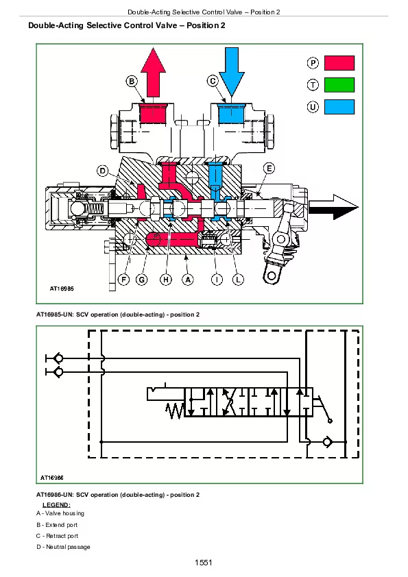
Double-Acting Selective Control Valve – Position 2
Double-Acting Selective Control Valve – Float Position
Double-Acting Sleeve Coupler Operation
Flow Divider Valve without Solenoid Valve Operation
Group 15: Diagnosis
Summary of References – Diagnosis
Safety Precautions
Diagnostic Information
Hydraulic Oil Warm-Up Procedure
Hydraulic System Major Test
Hydraulic System Diagnosis
Insufficient Pump Delivery
Hydraulic Functions Too Slow
Excessive Pump Pressure
Slow Hydraulic Pump Response
Excessive Pump Noise During Operation
Rockshaft Does Not Lift or Lifts Slowly
Rockshaft Does Not Lower or Lowers Slowly
Neutral Position Unstable, Rockshaft Drops After Engine Shut-Down
SCV Control Lever Does Not Return to Neutral Position
SCV Does Not Return to Neutral Position – SCV With Detent Position
SCV Does Not Remain In Detent Position – SCV With Detent Position
Remote Cylinder Does Not Extend or Retract
Remote Cylinder Settles Under Load
Remote Cylinder Operates Too Fast or Too Slow
Group 20: Tests
Summary of References – Tests
Specifications
Hydraulic System Tests – with SCV
Hydraulic System Tests
Transmission Hydraulic System
Pump Flow Test
SCV Relief Valve Test
SCV Leakage Test
EHS II Leakage Test
Rockshaft Lift Cycle Test
Group 25: Adjustments
Summary of References – Adjustments
Rockshaft Control Lever Friction Adjustment
Hitch Sensitivity Adjustment
Rockshaft Position Control Adjustment
Rockshaft Draft Control Adjustment
Electro-Hydraulic Hitch Sensing II Adjustment – Draft Sensor Rod Adjustment
Rockshaft Safety and Relief Valve Adjustment
Electro-Hydraulic Hitch Sensing Adjustment – Electro-Hydraulic Valve Adjustment
Electro-Hydraulic Hitch Sensing Adjustment – Backstop Limit Switch Adjustment
SCV Relief Valve Adjustment
Flow Divider Valve Adjustment
Group 30: Hydraulic System Schematics
Summary of References – Hydraulic System Schematics
Hydraulic Symbols
12/12-Speed Transmission – Steering System without Front-Wheel Drive
24/24-Speed Transmission – Steering System and Front-Wheel Drive with Mechanical Hi-Lo
24/24-Speed Transmission – Steering System and Front-Wheel Drive with Electro-Hydraulic Hi-Lo
SCV and Hitch with Flow Divider
Section 280: Miscellaneous
Group 10: Operational Checks
Operational Test on Front-Wheel Drive Axle
Checking Positive Front-Wheel Lead on Front-Wheel Drive Axle
Section 290: Air-Conditioning System
Group 05: Component Location
General Information
Air-Conditioning System Components
Heating System Components
Group 10: Theory of Operation
Summary of References – Theory of Operation
Theory of Operation Information
Principle of Heat Exchange
R134a Refrigerant
Operation of Air-Conditioning System – Air Flow
Air-Conditioning System Operation
Compressor
Condenser
Receiver-Drier
Expansion Valve
Group 15: Diagnosis, Tests and Adjustments
Summary of References — Diagnosis, Tests and Adjustments
Safety Equipment
In an Emergency
Storage of Refrigerant Containers
R134a Refrigerant
Important Note
Special or Essential Tools
Special Tools
Diagnostic Information
Air-Conditioning System Diagnosis
Pressure Deviations
Air-Conditioning System Troubleshooting
Failure Of Mechanical Type
Section 299: Special Tools
Group 05: Special Tools (Dealer-Fabricated)
Summary of References — Dealer-Manufactured Tools
Draft Control Adjusting Tool
Group 10: Special Tools (Available as Spare Parts)
Special Tools (Available as Spare Parts) – Summary of References
D01019AA – Single-Speed Hydraulic Hand Pump Assembly
FKM10475 – Adjusting Tool
JT05791A – Multimeter
JT05800 – Digital Thermometer
KJD10491—Diagnostic Interface Cable
JT02153—Current Clamp-On Probe
JDG10555 – Air-Conditioning Service Unit
FKM10470 – Pressure Measuring System (Stage 1)
FKM10471 – Pressure Measuring System (Stage 2)
FKM10472 – Flow Measurement System
FKM10472-4 – Temperature Sensor
KJD10589 – Hydraulic Test Kit for Transmission Diagnostics