Complete service repair manual with Electrical Wiring Diagrams for Komatsu 4D98 Series, 4D106 Series, S4D106 Series Diesel Engine, with all the technical information to maintain, diagnose, repair, rebuild like professional mechanics.
Komatsu 4D98 Series, 4D106 Series, S4D106 Series Diesel Engine workshop service repair manual includes:
* Numbered table of contents easy to use so that you can find the information you need fast.
* Detailed sub-steps expand on repair procedure information
* Numbered instructions guide you through every repair procedure step by step.
* Troubleshooting and electrical service procedures are combined with detailed wiring diagrams for ease of use.
* Notes, cautions and warnings throughout each chapter pinpoint critical information.
* Bold figure number help you quickly match illustrations with instructions.
* Detailed illustrations, drawings and photos guide you through every procedure.
* Enlarged inset helps you identify and examine parts in detail.
WEBD4D9801 – 4D98 Series, 4D106 Series, S4D106 Series Diesel Engine Shop Manual.pdf
PRODUCT DETAILS:
Total Pages: 182 pages
File Format: PDF
Language: English
MAIN SECTIONS
01 GENERAL
02 TROUBLESHOOTING
03. INSPECTION AND ADJUSTMENT
04. ENGINE BODY
05. LUBRICATION SYSTEM
06. COOLING SYSTEM
07. FUEL INJECTION PUMP/GOVERNOR
08. TURBOCHARGER (FOR 4TNE106T)
09. STARTING MOTOR
10. ALTERNATOR
11. SPECICAL SERVICE TOOLS
12. SERVICE STANDARDS
MAIN MENU…..0
FOREWORD …..4
FOR SAFE SERVICING…..5
PRECAUTIONS FOR SAFE SERVICING…..6
(A) Service Shop (Place) …..6
(B) Working Wear …..7
(C) Tools to Be Used …..7
(D) Use of Genuine Parts, Oil and Grease …..7
(E) Bolt and Nut Tightening Torques …..7
(F) Electrical Parts …..8
(G) Waste Treatment …..8
(H) Handling the Product …..9
CONTENTS …..10
1. GENERAL …..11
1.1 Engine Nomenclature …..12
1.2 Specifications …..13
1.3 Fuel Oil, Lubricating Oil and Cooling Water …..17
1.4 Engine External Views…..19
1.5 Structural Description…..20
1.6 How to Read This Manual…..21
(1) Range of Operation Explanation…..21
(2) How to Read The Explanations…..21
(3) Definition of Terms…..22
(4) Abbreviations…..22
1.7 Precautions for Service Work…..23
1.8 Tightening Torques for Standard Bolts and Nuts…..24
2. TROUBLESHOOTING …..25
2.1 Quick Reference Table for Troubleshooting…..26
2.2 Troubleshooting by Measuring Compression Pressure …..29
(1) Compression pressure measurement method…..29
(2) Standard compression pressure…..29
(3) Engine speed and compression pressure (reference)…..30
(4) Measured value and troubleshooting…..30
3. INSPECTION AND ADJUSTMENT…..31
3.1 Oil Inspection …..32
3.2 Cooling Water Inspection …..32
3.3 Inspecting Water Leak from Cooling Water System and Radiator …..32
3.4 Fan Belt Tension Inspection and Adjustment …..33
3.5 Adjusting the Valve Clearance …..34
3.6 Inspecting the Fuel Injection Valve Injection Pressure and Spray Pattern …..35
3.7 Fuel Injection Timing Inspection and Adjustment…..39
3.8 Adjusting the No-load Maximum (or Minimum) Revolutions …..40
3.9 Sensor Inspection …..41
3.10 Battery Inspection …..42
3.11 Adjusting Operation …..44
3.12 Long Storage …..45
3.13 Periodic Maintenance Schedule …..46
4. ENGINE BODY …..47
4.1 Introduction …..49
4.2 Cylinder Head …..50
(1) Components…..50
(2) Disassembly procedure:…..50
(3) Reassembly procedure:…..51
(4) Servicing points…..51
(5) Parts Inspection and measurement…..53
(6) Valve seat correction…..56
(7) Valve guide replacement…..58
(8) Valve stem seal replacement…..58
4.3 Gear Train and Camshaft …..59
(1) Components…..59
(2) Disassembly procedure:…..59
(3) Reassembly procedure:…..59
(4) Servicing points…..60
(5) Parts inspection and measurement…..62
(6) Oil seal replacement…..64
(7) Camshaft bushing replacement…..64
4.4 Cylinder block…..65
(1) Components…..65
(2) Disassembly procedure…..65
(3) Reassembly procedure…..65
(4) Servicing points…..66
(5) Parts inspection and measurement…..69
(6) Cylinder bore correction…..77
(7) Piston pin bushing replacement…..78
(8) Oil seal replacement…..78
5. LUBRICATION SYSTEM…..79
5.1 Lubrication System Diagram …..80
5.2 Trochoid Pump Components …..80
5.3 Disassembly (Reverse the procedure below for assembly) …..81
5.4 Servicing Points …..81
5.5 Parts Inspection and Measurement …..81
6. COOLING SYSTEM…..82
6.1 Cooling Water System …..83
6.2 Cooling Water Pump Components …..83
6.3 Disassembly (Reverse the procedure below for assembly)…..84
6.4 Servicing Points …..84
7. FUEL INJECTION PUMP/GOVERNOR…..85
7.1 Introduction …..86
7.2 Fuel Injection Pump …..86
(1) Fuel system diagram…..86
(2) Components…..87
(3) Disassembly procedure:…..87
(4) Assembly procedure…..88
(5) Servicing points…..88
(6) Parts inspection and measurement…..90
7.3 Fuel Injection Valve …..92
7.4 Fuel Feed Pump…..92
(1) Components…..92
(2) Disassembly procedure (Reverse the procedure below for assembly.)…..92
(3) Parts inspection and measurement…..92
7.5 Governor…..93
(1) Components…..93
(2) Disassembly procedure (Reverse the procedure for assembly.)…..93
(3) Parts inspection and measurement…..94
7.6 Special Service Tools for Disassembly/Assembly …..94
8. TURBOCHARGER (FOR 4TNE106T) …..95
8.1 Structure and Functions …..97
(1) Structural and functional outline…..97
(2) Structure…..98
(3) Components…..99
8.2 Service Standards …..100
(1) Service standards…..100
(2) Tightening torque…..100
8.3 Periodic Inspection Procedure …..101
(1) Periodic inspection intervals…..101
(2) Inspection procedure…..101
(3) Waste gate valve adjustment procedure…..102
8.4 Disassembly Procedure …..104
(1) Preparation for disassembly…..104
(2) Inspection before disassembly…..105
(3) Disassembly…..105
8.5 Washing and Inspection procedure…..106
(1) Washing…..106
(2) inspection procedure…..107
8.6 Reassembly Procedure …..110
(1) Preparation for reassembly…..110
(2) Reassembly…..110
8.7 Handling after Disassembly and Reassembly …..112
8.8 Troubleshooting …..113
9. STARTING MOTOR …..115
9.1 FOR 4TNE94/98…..117
9.1.1 Specifications…..117
9.1.2 Components…..118
9.1.3 Troubleshooting…..119
9.1.4 Names of parts and disassembly procedure…..120
9.1.5 Inspection and Maintenance…..124
(1) Armature…..124
(2) Field coil…..126
(3) Brush…..126
(4) Brush holder…..127
(5) Magnetic switch…..127
(6) Pinion clutch…..128
9.1.6 Service standards…..130
9.1.7 Assembly…..131
9.1.8 Characteristic test…..133
9.2 FOR 4TNEl06(T) …..134
9.2.1 Specifications…..134
9.2.2 Configuration drawing…..134
9.2.3 Troubleshooting…..135
9.2.4 Component names and disassembly procedure…..136
9.2.5 Disassembly procedure…..137
9.2.6 Inspection and maintenance…..139
(1) Armature…..139
(2) Field coil…..141
(3) Brush…..141
(4) Magnetic switch continuity test…..142
(5) Pinion…..143
(6) Ball bearing…..143
9.2.7 Assembly…..143
9.2.8 Adjustment…..144
9.2.9 Service standards…..145
10. ALTERNATOR …..146
10.1 For 4TNE94/98 …..147
10.1.1 Specifications …..147
10.1.2 Section view…..148
10.1.3 Troubleshooting…..149
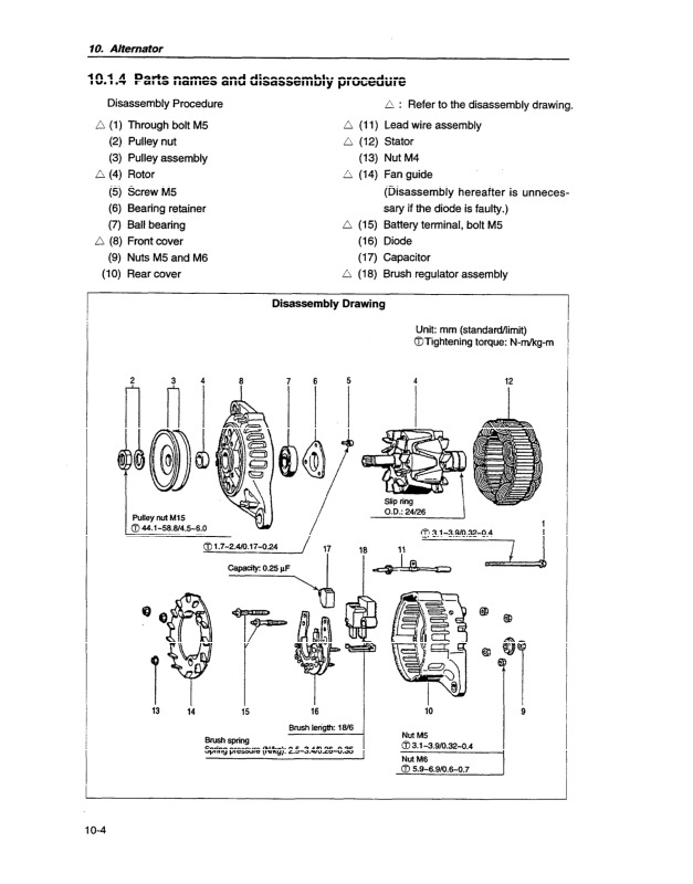
10.1.4 Parts names and disassembly procedure …..150
10.1.5 Inspection and overhaul …..153
(1) Diode…..153
(2) Rotor…..153
(3) Stator…..154
(4) Brush…..155
(5) Check of IC regulator…..155
10.1.6 Assembly …..157
10.1.7 Service standards …..158
10.1.8 Performance test …..159
10.2 For 4TNE106(T) …..160
10.2.1 Specifications (1) …..160
10.2.2 Exploded View …..161
10.2.3 Troubleshooting …..162
10.2.4 Disassembly Procedure …..163
10.2.5 Inspection and Maintenance …..164
10.2.6 Reassembly Procedure …..165
10.2.7 Performance Test …..166
11. SPECIAL SERVICE TOOLS…..168
11.1 Special Tools …..169
11.2 Measuring Instruments …..171
12. SERVICE STANDARDS …..174
12.1 Engine Tuning …..175
12.2 Engine Body …..176
(1) Cylinder head…..176
(2) Gear train and camshaft…..177
(3) Cylinder block…..178
12.3 Lubricating Oil System (Trochoid Pump) …..180
12.4 Tightening Torques for Main Bolts and Nuts …..181
Komatsu 4D98 Series, 4D106 Series, S4D106 Series Diesel Engine Repair Service Manuals