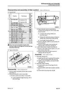
Complete service repair manual with Electrical Wiring Diagrams for Komatsu Hydraulic Excavators PC210LL-10, with all the shop information to maintain, diagnose, repair, and rebuild like professional mechanics.
Komatsu Hydraulic Excavators PC210LL-10 workshop service repair manual includes:
* Numbered table of contents easy to use so that you can find the information you need fast.
* Detailed sub-steps expand on repair procedure information
* Numbered instructions guide you through every repair procedure step by step.
* Troubleshooting and electrical service procedures are combined with detailed wiring diagrams for ease of use.
* Notes, cautions and warnings throughout each chapter pinpoint critical information.
* Bold figure number help you quickly match illustrations with instructions.
* Detailed illustrations, drawings and photos guide you through every procedure.
* Enlarged inset helps you identify and examine parts in detail.
CEBM029201 – Hydraulic Excavator PC210LL-10 Shop Manual (SN-A52001&up_Engine-6D107E-2).pdf
PRODUCT DETAILS:
Total Pages: 1,617 pages
File Format: PDF
Language: English
TABLE OF CONTENTS
CEBM029201 PC210LL-10 S/N A52001 &Up…..0
00 Index and foreword …..3
Index …..4
Foreword, safety and general information …..16
Important safety notice …..16
How to read the shop manual …..23
Explanation of terms for maintenance standard …..25
Handling equipment of fuel system devices …..27
Handling of intake system parts …..28
Handling of hydraulic equipment …..29
Method of disconnecting and connecting of push-pull type coupler …..31
Handling of electrical equipment …..34
How to read electric wire code …..42
Precautions when performing operation …..45
Practical use of KOMTRAX …..49
Standard tightening torque table …..50
List of abbreviation …..54
Conversion table …..59
01 Specification …..65
Table of contents …..65
Specifications …..65
Specification drawing …..66
Working range drawings …..69
Specifications …..70
Weight table …..72
Table of fuel, coolant, and lubricants …..74
10 Structure and function …..77
Table of contents …..78
Engine and cooling system …..79
Engine related parts …..79
KVGT …..81
EGR system piping drawing …..88
EGR system circuit diagram …..90
EGR valve …..92
EGR cooler …..94
KCCV layout drawing …..95
KCCV ventilator …..97
KDPF …..99
Cooling system …..103
Power train …..105
Power train system …..105
Swing circle …..0
Swing machinery …..0
Final drive …..0
Undercarriage and frame …..0
Track frame and idler cushion …..0
Hydraulic system …..114
Hydraulic equipment layout drawing …..114
Valve control …..0
Hydraulic tank …..118
CLSS …..120
Main pump …..125
Control valve …..150
Swing motor …..207
Travel motor …..0
PPC valve …..232
Solenoid valve …..248
Attachment circuit selector valve (for high pressure circuit) …..0
Attachment circuit selector valve (for low pressure circuit) …..0
Center swivel joint …..254
Accumulator …..256
Work equipment …..257
Work equipment …..257
Work equipment shim …..258
Bucket play adjustment shim …..259
Cab and its attachments …..261
Electrical system …..262
Electrical control system …..262
Machine monitor system …..315
KOMTRAX system …..337
Sensor …..340
20 Standard value tables …..361
Table of contents …..362
Standard service value table …..363
Standard value table for engine …..363
Standard value table for machine …..365
Standard value table for electrical system …..378
30 Testing and adjusting …..389
Table of contents …..390
General information on testing and adjusting …..391
Engine and cooling system …..396
Power train …..430
Undercarriage and frame …..431
Hydraulic system …..432
Cab and its attachments …..464
Electrical system …..468
Pm clinic …..545
40 Troubleshooting…..557
Table of contents…..558
General information on troubleshooting …..565
Troubleshooting by failure code (Display of code) …..1119
Troubleshooting of hydraulic and mechanical system (H-mode) …..1205
Troubleshooting of engine (S-mode) …..1272
50 Disassembly and assembly…..1301
Table of Contents…..1302
General information on disassembly and assembly…..1304
Engine and Cooling System…..1319
Power train…..1413
Undercarriage and frame…..1433
Hydraulic system…..1453
Work equipment…..1482
Cab and its attachments…..1491
Electrical system…..1533
60 Maintenance standard …..1551
Table of contents …..1552
Engine and cooling system …..1553
Power train …..1555
Undercarriage and frame …..1562
Hydraulic system …..1574
Work equipment …..1606
80 Appendix …..1619
Table of contents …..1620
Air conditioner components …..1621
90 Diagrams and drawings …..1705
Table of contents …..1706
Hydraulic circuit diagram …..1707
Symbols in hydraulic circuit diagram …..1707
Hydraulic circuit diagram …..1710
Electric circuit diagram …..1712
Symbols in electric circuit diagram …..1712
Electric circuit diagram …..1715
Electric circuit diagram for air conditioner unit …..1722
Connector List and Stereogram…..1723
Chassis…..1723
Operator’s Compartment…..1724
Cab…..1725
Engine Compartment…..1726
Komatsu Hydraulic Excavators PC210LL Repair Service Manuals
