tm134419 – 5085E, 5090E, 5090EL, and 5100E (FT4) Tractors Diagnostic Technical Manual Technical Manual.pdf
INSTANT DOWNLOAD
Complete Diagnostics & Tests technical manual with Electrical Wiring Diagrams for John Deere Tractors 5085E, 5090E, 5090EL, 5100E (FT4) (North America) (SN F_400001- ), with all the shop information to maintain, diagnostic, repair, service like professional mechanics.
John Deere Tractors 5085E, 5090E, 5090EL, 5100E workshop operation tests manual includes:
* Numbered table of contents easy to use so that you can find the information you need fast.
* Detailed sub-steps expand on repair procedure information
* Numbered instructions guide you through every repair procedure step by step.
* Troubleshooting and electrical service procedures are combined with detailed wiring diagrams for ease of use.
* Notes, cautions and warnings throughout each chapter pinpoint critical information.
* Bold figure number help you quickly match illustrations with instructions.
* Detailed illustrations, drawings and photos guide you through every procedure.
* Enlarged inset helps you identify and examine parts in detail.
Total Pages: 1,964 pages
File Format: PDF (bookmarked, ToC, Searchable, Printable, high quality)
Language: English
MAIN SECTIONS
Foreword
General Information
Safety
General References
Technical Specific References
Diagnostic Trouble Codes
CCU Code Diagnostics
ECU Code Diagnostics
EIC Code Diagnostics
ICC Code Diagnostics
PTR Code Diagnostics
Observable Symptoms and System Diagnostics
General References
Engine Diagnostics
Fuel, Air Intake, Exhaust, and Cooling Diagnostics
Electrical Diagnostics
Electronic Control Unit Diagnostics
Drive Systems and Transmission Diagnostics
Steering and Brakes Diagnostics
Hydraulic Diagnostics
Cab/Open Operator`s Station Diagnostics
Engine
General References
Engine Component and Connector Information
Engine Tests and Adjustments
Fuel, Air Intake, Exhaust, and Cooling
General References
Fuel, Air Intake, Exhaust, and Cooling Theory of Operation
Electrical General and Theory of Operation
General References
Turn Signal Switch and Warning Lights
Wipers
Rear Wipers
Instrument Cluster Control (ICC)
Electrohydraulic Control Unit (EHC)
Power Train Reverser (PTR)
Chassis Control Unit (CCU)
Engine Control Unit (ECU)
Controller Area Network
Electrical Schematics
General References
Key Switch, Starter and Alternator (SE1)
Neutral Start (SE2)
Accessory Power (SE3)
Horn (SE4)
Light Switch and Headlights (SE5A)
Tail, Turn, and Brake Lights (SE5B)
Cab Work Lighting (SE5C)
Open Operator Station Work Lighting (SE5D)
Turn Signal Switch and Warning Lights (SE6)
Junction Block Power (SE9)
Trailer Connector (SE10)
Loader Lights (SE12)
Back-Up Alarm (SE13A)
Beacon Light (SE13B)
Mid-Mount SCV (SE14)
Power Outlets (SE15)
Heating (SE16)
Air Conditioning (SE17)
Front Windshield Wiper and Washer (SE19)
Rear Windshield Wiper and Washer (SE21)
Dome Light, Door Switch, and Radio (SE22)
Air Seat (SE23)
Instrument Cluster Control (ICC) (SE24)
Seat, Rear PTO and Wheel Speed (SE25)
ELX Relay and Fuses (SE26)
Mechanical Front-Wheel Drive (MFWD) (SE27)
Brake Switch (SE28)
Electrohydraulic Control Unit (EHC) (SE29A)
Power Train Reverser Control Unit (PTR) (SE29B)
Chassis Control Unit (CCU) (SE29C)
Engine Control Unit (ECU) (SE30)
Controller Area Network (SE32)
Electrical Components and Connectors
General References
Key Switch, Starter and Alternator (SE1)
Neutral Start (SE2)
Accessory Power (SE3)
Horn (SE4)
Light Switch and Headlights (SE5A)
Tail, Turn, and Brake Lights (SE5B)
Cab Work Lighting (SE5C)
Open Operator Station Work Lighting (SE5D)
Turn Signal Switch and Warning Lights (SE6)
Junction Block Power (SE9)
Trailer Connector (SE10)
Loader Lights (SE12)
Back-Up Alarm (SE13A)
Beacon Light (SE13B)
Mid-Mount SCV (SE14)
Power Outlets (SE15)
Heating (SE16)
Air Conditioning (SE17)
Front Windshield Wiper and Washer (SE19)
Rear Windshield Wiper and Washer (SE21)
Dome Light, Door Switch and Radio (SE22)
Air Seat (SE23)
Instrument Cluster Control (ICC) (SE24)
Seat, Rear PTO and Wheel Speed (SE25)
ELX Relay and Fuses (SE26)
Mechanical Front-Wheel Drive (MFWD) (SE27)
Brake Switch (SE28)
Electrohydraulic Control Unit (EHC) (SE29A)
Power Train Reverser Control Unit (PTR) (SE29B)
Chassis Control Unit (CCU) (SE29C)
Engine Control Unit (ECU) (SE30)
Controller Area Network (SE32)
Fuses and Relays
Ground Points
Interconnects
Wiring Harnesses
Electrical Tests and Adjustments
General References
Tests and Adjustments
Electronic Control Units
General References
Calibrations, Preliminary Checks and Operational Checks
Theory of Operation
Schematics
Component and Connector Information
Tests and Adjustments
Chassis Control Unit (CCU)
Engine Control Unit (ECU)
Engine Interface Control Unit (EIC)
Instrument Cluster Control Unit (ICC)
Power Train Reverser (PTR)
Drive Systems and Transmissions
General References
Calibrations, Preliminary Checks and Operational Checks
Drive Systems and Transmission Theory of Operation
Drive Systems and Transmission Schematics
Drive Systems and Transmission Component and Connector Information
Drive Systems Tests and Adjustments
Transmission Tests and Adjustments
Steering and Brakes
General References
Brake Calibrations, Preliminary Checks and Operational Checks
Steering Calibrations, Preliminary Checks and Operational Checks
Brake Theory of Operation
Steering Theory of Operation
Brake Schematics
Steering Schematics
Brake Component and Connector Information
Steering Component and Connector Information
Brake Tests and Adjustments
Steering Tests and Adjustments
Hydraulics
General References
Calibrations, Preliminary Checks and Operational Checks
General Hydraulics Theory of Operation
Mechanical Hitch Theory of Operation
Hydraulic Filter Theory of Operation
Hydraulic Pump Theory of Operation
Dual Mid-Mount SCV Theory of Operation
Power Beyond Theory of Operation
Quick Disconnect Coupler Theory of Operation
Dual Rear SCV Theory of Operation
Triple Mid-Mount SCV Theory of Operation
Triple Rear SCV Theory of Operation
Schematics
Component and Connector Information
Tests and Adjustments
Cab/Open Operator`s Station
General References
Calibrations, Preliminary Checks and Operational Checks
HVAC Theory of Operation
Seat Theory of Operation
Schematics
Component and Connector Information
Tests and Adjustments
Special Tools
General References
Dealer Fabricated and Service Tools
tm134419 – 5085E, 5090E, 5090EL, and 5100E (FT4) Tractors Diagnostic Technical Manual
Table of Contents
Foreword
Section 210: General Information
Group 05A: Safety
Work In Ventilated Area
Recognize Safety Information
Avoid Backover Accidents
Prevent Machine Runaway
Avoid Contact with Agricultural Chemicals
Clean Vehicle of Hazardous Pesticides
Use a Safety Chain
Work in Clean Area
Decommissioning — Proper Recycling and Disposal of Fluids and Components
Avoid Harmful Asbestos Dust
Avoid Hot Exhaust
Clean Exhaust Filter Safely
Handle Fuel Safely—Avoid Fires
Prepare for Emergencies
Handle Fluids Safely—Avoid Fires
Avoid High-Pressure Fluids
Install All Guards
Use Proper Lifting Equipment
Illuminate Work Area Safely
Live With Safety
Service Machines Safely
Support Machine Properly
Remove Paint Before Welding or Heating
Park Machine Safely
Stay Clear of Rotating Drivelines
Follow Safety Instructions
Use Proper Tools
Service Tires Safely
Keep ROPS Installed Properly
Construct Dealer-Made Tools Safely
Practice Safe Maintenance
Understand Signal Words
Replace Safety Signs
Avoid Heating Near Pressurized Fluid Lines
Wear Protective Clothing
Service Accumulator Systems Safely
Handling Batteries Safely
Handle Agricultural Chemicals Safely
Service Cooling System Safely
Use Steps and Handholds Correctly
Transport Tractor Safely
Group 05B: General References
General Information – Summary of References
Regions and Country Versions
Deliver Safely
Glossary of Terms
Information Available in Sections, Groups and Subgroups
Trademarks
Group 05C: Technical Specific References
Features and Accessories
Metric Bolt and Screw Torque Values
Unified Inch Bolt and Screw Torque Values
Group 10: Understanding Tractor Serial Numbers
Product Identification Number
Section 211: Diagnostic Trouble Codes
Group CCU: CCU Code Diagnostics
CCU 000096.03 – Fuel Level Sensor Circuit Voltage High
CCU 000096.04 – Fuel Level Sensor Circuit Voltage Low
CCU 000237.02 – VIN Security Data Conflict
CCU 000237.31 – VIN Security Messages Missing
CCU 000569.05 – Rear Differential Lock Solenoid Circuit Fault
CCU 000628.02 – CCU EOL Data Fault
CCU 000630.14 – Rear PTO Configuration Invalid
CCU 001638.00 – Hydraulic Oil Temperature Very Hot
CCU 001638.03 – Hydraulic Oil Temperature Sensor Circuit Voltage High
CCU 001638.04 – Hydraulic Oil Temperature Sensor Circuit Voltage Low
CCU 001638.16 – Hydraulic Oil Temperature High
CCU 001883.00 – Rear PTO Overspeed
CCU 001883.01 – Rear PTO Underspeed
CCU 002818.31 – Operator Presence Switch Not Activated
CCU 003509.03 – Sensor Supply Voltage Out of Range High
CCU 003509.04 – Sensor Supply Voltage Out of Range Low
CCU 523316.04 – Switched Supply Voltage Low
CCU 523844.12 – Front Differential Lock Solenoid Fault
CCU 523907.02 – PTO Remote Enable Switch Conflict
CCU 523908.02 – Rear PTO External Switch Conflict
CCU 524037.02 – MFWD Switch Circuit Fault
CCU 524223.03 – Differential Lock Switch Circuit Voltage High
CCU 524224.14 – PTO Switch Voltage Mismatch
CCU 524235.05 – MFWD Solenoid Circuit Fault
CCU 524252.05 – Rear PTO Solenoid Circuit Fault
CCU 524255.31 – Rear Remote PTO Enabled
Group ECU: ECU Code Diagnostics
ECU – Non-Tractor ECU Codes
ECU 000152.12 – Control Unit Fault
ECU 000152.14 – Control Unit Fault
ECU 000152.16 – Control Unit Fault
ECU 000158.31 – Mismatch Between ELX and Start Inputs
ECU 000237.02 – VIN Security Data Invalid
ECU 000237.13 – VIN Option Code Security Data Conflict
ECU 000237.31 – VIN Security Data Missing
ECU 000647.03 – Engine Fan Circuit Current High
ECU 000695.19 – Unapproved Engine Speed Request
ECU 001110.31 – Engine Protection System Activated
ECU 001550.05 – Air Conditioner Compressor Current Low
ECU 001550.06 – Air Conditioner Compressor Current High
ECU 003353.31 – Alternator Fault
ECU 003695.03 – Diesel Particulate Filter Regeneration Inhibit Switch Shorted To Battery
ECU 003695.04 – Diesel Particulate Filter Regeneration Inhibit Switch Shorted To Ground
ECU 003695.05 – Diesel Particulate Filter Regeneration Inhibit Switch Circuit Open
ECU 003695.13 – Diesel Particulate Filter Regeneration Inhibit Switch Out Of Calibration
ECU 003695.14 – Diesel Particulate Filter Regeneration Special Instructions
ECU 003696.03 – Diesel Particulate Filter Regeneration Force Switch Shorted To Battery
ECU 003696.04 – Diesel Particulate Filter Regeneration Force Switch Shorted To Ground
ECU 003696.05 – Diesel Particulate Filter Regeneration Force Switch Current Low
ECU 004765.00 – Exhaust Temperature Very High
ECU 524225.31 – Engine Start Protection Bypass Detected
Group EIC: EIC Code Diagnostics
EIC 000628.02 – EOL Control Unit Fault
EIC 000628.12 – EIC Programming Fault
EIC 000630.13 – EIC Calibration Fault/Not Calibrated
EIC 002000.09 – ECU Message Missing
EIC 003695.14 – Diesel Particulate Filter Regeneration Fault
EIC 003719.15 – Diesel Particulate Filter Regeneration Fault
EIC 523702.14 – EIC Control Unit Fault
EIC 523702.31 – EIC Control Unit Fault
Group ICC: ICC Code Diagnostics
ICC 000107.00 – Air Filter Restricted
ICC 000167.04 – Alternator Voltage Below Normal
ICC 000237.02 – VIN Security Mismatch
ICC 000237.12 – VIN Security: More Than One ECU Address Claimed
ICC 000237.14 – VIN Security Not Enabled
ICC 000237.31 – VIN Security Messages Missing
ICC 000628.02 – ICC EOL Data Fault
ICC 000628.12 – ICC Programming Fault
ICC 000630.02 – ICC Calibration Memory Fault
ICC 000630.11 – Control Software Internal Fault
ICC 000630.13 – ICC Calibration Fault/Not Calibrated
ICC 000916.14 – Vehicle Service Indication
ICC 000920.06 – Audible Alarm Current High
ICC 002000.09 – ECU Message Missing
ICC 002003.09 – PTR Message Missing
ICC 002007.09 – RPT Message Missing
ICC 002023.06 – ICC Current High
ICC 002047.09 – CCU Message Missing
ICC 002145.06 – Control Unit Supply Circuit Fault
ICC 002368.05 – Left Turn Signal Current Low
ICC 002368.06 – Left Turn Signal Current High
ICC 002370.05 – Right Turn Signal Current Low
ICC 002370.06 – Right Turn Signal Current High
ICC 002818.31 – Operator Presence Switch Not Activated
ICC 002876.02 – Turn-Signal Lever Malfunction
ICC 003695.02 – Regeneration Switch Malfunction
ICC 003696.02 – Regeneration Switch Malfunction
Group PTR: PTR Code Diagnostics
PTR 000084.07 – Excessive Wheel Speed Detected During Calibration
PTR 000158.01 – System Switched Voltage Low
PTR 000162.02 – High/Low Switch Circuit Conflict
PTR 000162.31 – High, Low Switch Stuck On
PTR 000190.18 – Engine Speed Missing During Shift
PTR 000191.00 – Excessive Top Shaft Speed During Calibration
PTR 000191.17 – Top Shaft Speed Too Low
PTR 000598.02 – Clutch Switch Open With Pedal Up
PTR 000598.04 – Clutch Switch Signal Failed Low
PTR 000628.02 – EOL Data Fault
PTR 000630.14 – Tractor Model Out Of Range/Transmission Calibration Value High
PTR 000752.03 – Power Shuttle Potentiometer Input Voltage High
PTR 000752.04 – Power Shuttle Potentiometer Input Voltage Low
PTR 001504.10 – Seat Switch Closed Too Long
PTR 002820.31 – Operator Not Present During Shift
PTR 002825.07 – Not Valid Neutral Park Command
PTR 003509.03 – PTR Sensor Supply Voltage High
PTR 003509.04 – PTR Sensor Supply Voltage Low
PTR 521233.05 – High Valve Driver Fault
PTR 521234.05 – Low Valve Driver Fault
PTR 521235.05 – Reverse Valve Driver Fault
PTR 522456.07 – Speed Control Lever Park and Neutral Switch Conflict
PTR 522456.31 – Speed Control Lever Transition Without Using Clutch Pedal
PTR 523953.02 – Speed Control Lever Sensor Circuit Conflict
PTR 523959.31 – No Wheel Speed While in Gear
PTR 523966.31 – Come Home Detected
PTR 524020.31 – Reverser in Gear at Power-Up
PTR 524021.31 – Directional Reverser Lever Switch Circuit Fault
PTR 524160.02 – Not Valid Neutral/Not Neutral Switch
PTR 524173.02 – Clutch Pedal Compare Error
PTR 524173.14 – Sync Lever Shift Without Clutch Pedal Engaged
PTR 524173.15 – Clutch Pedal Voltage High
PTR 524173.16 – Both Clutch Pedals Voltage High
PTR 524173.17 – Clutch Pedal Voltage Low
PTR 524173.18 – Both Clutch Pedals Voltage Low
PTR 524230.05 – Enable Valve Driver Fault
PTR 524230.07 – Enable Valve Stuck
PTR 524234.03 – Pressure Sensor Voltage High
PTR 524234.04 – Pressure Sensor Voltage Low
PTR 524254.03 – Transmission Enable Valve Power High
PTR 524254.04 – Transmission Enable Valve Power Low
PTR 524267.15 – High Speed Shuttle Shift
Section 212: Observable Symptoms and System Diagnostics
Group 05B: General References
Observable Symptoms and System Diagnostics – Summary of References
Group 20: Engine Diagnostics
Engine System Problems
Group 30: Fuel, Air Intake, Exhaust, and Cooling Diagnostics
Fuel and Air System Problems
Group 40: Electrical Diagnostics
Back-Up Alarm Problems
Charging System Problems
Door Switch and Dome Light Problems
Electrical Connector Problems
Horn Problems
Lighting System Problems
Power Outlet Problems
Starting System Problems
Trailer Connector and Junction Block Problems
Group 45: Electronic Control Unit Diagnostics
CAN System Diagnosis
Chassis Control Unit (CCU) Problems
Codes After Adding / Removing Control Units
Control Unit Problems
Control Unit Programming Failed
Control Unit System Diagnosis
Engine Control Unit (ECU) Problems
Instrument Cluster Control (ICC) Problems
Power Train Reverser (PTR) Problems
Programming Multiple Control Units
Group 50: Drive Systems and Transmission Diagnostics
MFWD Problems
MFWD System Diagnosis
PowrReverser Transmission Problems
PowrReverser Transmission System Diagnosis
Rear PTO Problems
Rear PTO System Diagnosis
Group 60: Steering and Brakes Diagnostics
Brake Problems
Brake System Diagnosis
Steering Problems
Steering System Diagnosis
Group 70: Hydraulic Diagnostics
Mechanical Hitch Problems
Mechanical Hitch System Diagnosis
Mid-Mount SCV Problems
Mid-Mount SCV System Diagnosis
Rear SCV Problems
Rear SCV System Diagnosis
Group 90: Cab/Open Operator’s Station Diagnostics
HVAC Problems
HVAC System Diagnosis
Radio Problems
Seat Problems
Wiper Problems
Section 220: Engine
Group 05B: General References
Engine – Summary of References
Engine Information
Group 40AA: Engine Component and Connector Information
Engine Components
Group 50AA: Engine Tests and Adjustments
Engine Test Procedures and Adjustments
Engine Performance Testing
Engine Performance Variables
Section 230: Fuel, Air Intake, Exhaust, and Cooling
Group 05B: General References
Fuel, Air Intake, Exhaust, and Cooling – Summary of References
Fuel, Air Intake, Exhaust, and Cooling Information
Group 20AA: Fuel, Air Intake, Exhaust, and Cooling Theory of Operation
Air Intake System Theory of Operation
Cooling System Theory of Operation
Fuel System Theory of Operation
DEF Tank Header Theory of Operation
Exhaust Aftertreatment System Theory of Operation
Section 240A: Electrical General and Theory of Operation
Group 05B: General References
Electrical General and Theory of Operation – Summary of References
Circuit Malfunctions
Circuit Types
Electrical Designators
Electrical Procedure
Electrical Schematic Symbols
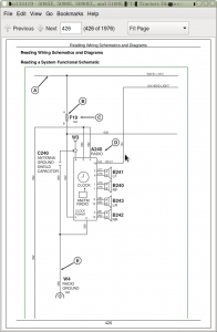
Reading Wiring Schematics and Diagrams
Relay Circuit Types
Troubleshooting Unresolved Electrical/Electronic Problems
Using a Digital Multimeter
Using a Probe Light
Visually Inspect Electrical System
Wiring Diagram and Schematic Information
Group 20DD: Turn Signal Switch and Warning Lights
Turn Signal Switch and Warning Lights Theory of Operation
Group 20MA: Wipers
Front Wiper Switch Theory of Operation
Group 20MC: Rear Wipers
Rear Wiper Switch Theory of Operation
Group 20PA: Instrument Cluster Control (ICC)
Instrument Cluster Control (ICC) Theory of Operation
Instrument Cluster Alarm Theory of Operation
Group 20UA: Electrohydraulic Control Unit (EHC)
Electrohydraulic Control Unit (EHC) Theory of Operation
Group 20UC: Power Train Reverser (PTR)
Power Train Reverser (PTR) Theory of Operation
Group 20UD: Chassis Control Unit (CCU)
Chassis Control Unit (CCU) Theory of Operation (PR Transmission)
Fuel Level Sensor Theory of Operation (PR Transmission)
Group 20VA: Engine Control Unit (ECU)
Engine Control Unit (ECU) Theory of Operation
Group 20WA: Controller Area Network
CAN Communication System Theory Of Operation
Section 240B: Electrical Schematics
Group 05B: General References
Electrical Schematics – Summary of References
Group 30AA: Key Switch, Starter and Alternator (SE1)
Key Switch, Starter and Alternator Schematic and Circuit Diagram (SE1)
Group 30AC: Neutral Start (SE2)
Neutral Start Schematic and Circuit Diagram (SE2)
Group 30BA: Accessory Power (SE3)
Accessory Power Schematic and Circuit Diagram (SE3)
Group 30CA: Horn (SE4)
Horn Schematic and Circuit Diagram (SE4)
Group 30DA: Light Switch and Headlights (SE5A)
Light Switch and Headlights Schematic and Circuit Diagram (SE5A)
Group 30DB: Tail, Turn, and Brake Lights (SE5B)
Tail, Turn, and Brake Lights Schematic and Circuit Diagram (SE5B)
Group 30DC: Cab Work Lighting (SE5C)
Cab Work Lighting Schematic and Circuit Diagram (SE5C)
Group 30DD: Open Operator Station Work Lighting (SE5D)
Open Operator Station Work Lighting Schematic and Circuit Diagram (SE5D)
Group 30DE: Turn Signal Switch and Warning Lights (SE6)
Turn Signal Switch and Warning Lights Schematic and Circuit Diagram (SE6)
Group 30FA: Junction Block Power (SE9)
Junction Block Power Schematic and Circuit Diagram (SE9)
Group 30GA: Trailer Connector (SE10)
Trailer Connector Schematic and Circuit Diagram (SE10)
Group 30HA: Loader Lights (SE12)
Loader Lights Schematic and Circuit Diagram (SE12)
Group 30IA: Back-Up Alarm (SE13A)
Back-Up Alarm Schematic and Circuit Diagram (SE13A)
Group 30IB: Beacon Light (SE13B)
Beacon Light Schematic and Circuit Diagram (SE13B)
Group 30JA: Mid-Mount SCV (SE14)
Mid-Mount SCV Schematic and Circuit Diagram (SE14)
Group 30KA: Power Outlets (SE15)
Power Outlets Schematic and Circuit Diagram (SE15)
Group 30LA: Heating (SE16)
Heating Schematic and Circuit Diagram (SE16)
Group 30LB: Air Conditioning (SE17)
Air Conditioning Schematic and Circuit Diagram (SE17)
Group 30MA: Front Windshield Wiper and Washer (SE19)
Front Windshield Wiper and Washer Schematic and Circuit Diagram (SE19)
Group 30MC: Rear Windshield Wiper and Washer (SE21)
Rear Windshield Wiper and Washer Schematic and Circuit Diagram (SE21)
Group 30NA: Dome Light, Door Switch, and Radio (SE22)
Dome Light, Door Switch, and Radio Schematic and Circuit Diagram (SE22)
Group 30OA: Air Seat (SE23)
Air Seat Schematic and Circuit Diagram (SE23)
Group 30PA: Instrument Cluster Control (ICC) (SE24)
Instrument Cluster Control (ICC) Schematic and Circuit Diagram (SE24)
Group 30QA: Seat, Rear PTO and Wheel Speed (SE25)
Seat Switch, Rear PTO Switch and Wheel Speed Sensor Schematic and Circuit Diagram (SE25)
Group 30RA: ELX Relay and Fuses (SE26)
ELX Relay and Fuses Schematic and Circuit Diagram (SE26)
Group 30SA: Mechanical Front-Wheel Drive (MFWD) (SE27)
Mechanical Front-Wheel Drive (MFWD) Schematic and Circuit Diagram (SE27)
Group 30TA: Brake Switch (SE28)
Brake Switch Schematic and Circuit Diagram (SE28)
Group 30UA: Electrohydraulic Control Unit (EHC) (SE29A)
Electrohydraulic Control Unit (EHC) Schematic and Circuit Diagram (SE29A)
Group 30UC: Power Train Reverser Control Unit (PTR) (SE29B)
Power Train Reverser Control Unit (PTR) Schematic and Circuit Diagram (SE29B)
Group 30UD: Chassis Control Unit (CCU) (SE29C)
Chassis Control Unit (CCU) Schematic and Circuit Diagram (PR Transmission) (SE29C)
Group 30VA: Engine Control Unit (ECU) (SE30)
Engine Control Unit (ECU) Schematic and Circuit Diagram (SE30)
Group 30WA: Controller Area Network (SE32)
Controller Area Network Schematic and Circuit Diagram (SE32)
Section 240C: Electrical Components and Connectors
Group 05B: General References
Electrical Components and Connectors – Summary of References
Group 40AA: Key Switch, Starter and Alternator (SE1)
F26 (125A) Fusible Link
G01 Battery
G02 Alternator
M01 Starter Motor/Solenoid
S01 Key Switch
Group 40AC: Neutral Start (SE2)
K11 Neutral Relay
K18 Neutral Start Relay
Group 40BA: Accessory Power (SE3)
K07 Accessory Relay
Group 40CA: Horn (SE4)
H01 Horn
S05 Horn Switch
Group 40DA: Light Switch and Headlights (SE5A)
E01 Right Front High/Low Beam Headlight
E02 Left Front High/Low Beam Headlight
K27 Headlight Relay
S06 Light Switch
S12 HI/LO Beam Flash-to-Pass Switch
S45 HI/LO Headlight Switch
V01 Diode Block
Group 40DB: Tail, Turn, and Brake Lights (SE5B)
H02 Right Tail/Turn Light
H03 Left Tail/Turn Light
H08 Left Brake Light
H09 Right Brake Light
H12 Right Tail/Turn Light
H13 Left Tail/Turn Light
Group 40DC: Cab Work Lighting (SE5C)
E03 Left Front Work Light
E04 Right Front Work Light
E05 Left Rear Work Light
E06 Right Rear Work Light
E07 Left Front Work Light
E08 Right Front Work Light
E09 Right Rear Work Light
E10 Left Rear Work Light
Group 40DD: Open Operator Station Work Lighting (SE5D)
E11 Left Rear Work Light
E12 Right Rear Work Light
E13 Right Front Work Light
E14 Left Front Work Light
Group 40DE: Turn Signal Switch and Warning Lights (SE6)
H04 Right Front Warning Light
H05 Left Front Warning Light
H10 Right Rear Warning Light
H11 Left Rear Warning Light
S43 Turn Signal Switch
Group 40FA: Junction Block Power (SE9)
X02 Junction Block
Group 40GA: Trailer Connector (SE10)
X01 Trailer Connector
Group 40HA: Loader Lights (SE12)
E15 Left Front Loader Light
E16 Right Front Loader Light
S26 Loader Light Switch
Group 40IA: Back-Up Alarm (SE13A)
H06 Back-Up Alarm
Group 40IB: Beacon Light (SE13B)
H07 Beacon Light
S25 Beacon Light Switch
Group 40JA: Mid-Mount SCV (SE14)
K25 Mid-Mount SCV Retract (Black) 3rd Function Relay
K26 Mid-Mount SCV Extend (Gray) 3rd Function Relay
S19 Mid-Mount SCV 3rd Function Switch
V06 Mid-Mount SCV Retract Solenoid Diode
V07 Mid-Mount SCV Extend Solenoid Diode
Y03 Mid-Mount SCV Retract (Black) 3rd Function Solenoid Valve
Y04 Mid-Mount SCV Extend (Gray) 3rd Function Solenoid Valve
Group 40KA: Power Outlets (SE15)
X03 Convenience Outlet
X05 Auxiliary Power Strip
X06 Power Outlet
Group 40LA: Heating (SE16)
M02 Left HVAC Blower Motor
M03 Right HVAC Blower Motor
R03 HVAC Resistor
S08 HVAC Blower Switch
Group 40LB: Air Conditioning (SE17)
B07 A/C Deicing Switch
B08 A/C High/Low Pressure Switch
M04 A/C Compressor Clutch
S09 A/C ON/OFF Switch
V05 A/C Compressor Clutch Diode
Group 40MA: Front Windshield Wiper and Washer (SE19)
M05 Front Wiper Motor
M06 Front Washer Pump
S30 Front Wiper Switch
Group 40MC: Rear Windshield Wiper and Washer (SE21)
M07 Rear Wiper Motor
M08 Rear Washer Pump
S11 Rear Wiper Switch
Group 40NA: Dome Light, Door Switch and Radio (SE22)
A03 Dome Light and Switch Assembly
A04 Radio
A04X1 Radio Connector
A04X5 Radio Antenna Connector
B240 Right Speaker
B241 Left Speaker
E18 Right-Hand Console Light
S13 Left Door Switch
W125 Antenna Base
Group 40OA: Air Seat (SE23)
A05 Air Seat Assembly
Group 40PA: Instrument Cluster Control (ICC) (SE24)
A01 Instrument Cluster Control (ICC)
A01X1 Instrument Control Cluster (ICC) Connector
A01X2 Instrument Control Cluster (ICC) Connector
H18 Instrument Cluster Alarm
S35 Exhaust Filter Cleaning Switch
S36 Roll Mode Switch
Group 40QA: Seat, Rear PTO and Wheel Speed (SE25)
B10 Wheel Speed Sensor
S02 Rear PTO ON/OFF Switch
S04 Seat Switch
Group 40RA: ELX Relay and Fuses (SE26)
ELX Relay and Fuses Component and Connectors
Group 40SA: Mechanical Front-Wheel Drive (MFWD) (SE27)
S16 MFWD Switch
Group 40TA: Brake Switch (SE28)
S17 Brake Pedal Switch
Group 40UA: Electrohydraulic Control Unit (EHC) (SE29A)
A06 Electrohydraulic Control Unit (EHC)
A06X1 Electrohydraulic Control Unit (EHC) Connector
A06X2 Electrohydraulic Control Unit (EHC) Connector
A06X3 Electrohydraulic Control Unit (EHC) Connector
Group 40UC: Power Train Reverser Control Unit (PTR) (SE29B)
A06A Power Train Reverser (PTR)
B09 Top Shaft Speed Sensor
B12 Enable Pressure Sensor
B13 Clutch Pedal Position Sensor
B21 Power Shuttle Control
S14 Forward Neutral Reverse (FNR) Switch
S15 Clutch Pedal Disengage Switch
S18 Park Switch
S23 High/Low Shifter Switch
S34 Speed Lever Neutral Switch
Y05 Transmission Forward (Low) Solenoid Valve
Y06 Transmission Reverse Solenoid Valve
Y07 Clutch Enable Solenoid Valve
Y10 Transmission Forward (High) Solenoid Valve
Group 40UD: Chassis Control Unit (CCU) (SE29C)
A06B Chassis Control Unit (CCU) (PR Transmission)
B01 Fuel Level Sensor (PR Transmission)
B05 PTO Speed Sensor (PR Transmission)
B11 Hydraulic Oil Temperature Sensor (PR Transmission)
Y01 PTO Solenoid Valve (PR Transmission)
Y02 MFWD Solenoid (PR Transmission)
Group 40VA: Engine Control Unit (ECU) (SE30)
A5505 Engine Control Unit (ECU)
A5505X1 Engine Control Unit (ECU) Connector
A5505X2 Engine Control Unit (ECU) Connector
A5505X3 Engine Control Unit (ECU) Connector
A5507 DEF Tank Header
B23 Hand Throttle Position Sensor
B32 Foot Throttle Position Sensor
B5101 Oil Pressure Sensor
B5102 Exhaust Pressure Sensor
B5103 EGR Delta Pressure Sensor
B5104 Intake Manifold Pressure Sensor
B5105 Crankcase Pressure Sensor
B5107 Inlet Fuel Pressure Sensor
B5113 Rail Pressure Sensor
B5205 Intercooler Outlet Temperature Sensor
B5206 Manifold Air Temperature Sensor
B5207 EGR Temperature Sensor
B5208 Coolant Temperature Sensor
B5209 Fuel Temperature Sensor
B5217 DOC/SCR Temperature Sensor
B5301 Crank Position Sensor
B5302 Cam Position Sensor
B5500 Compressor Inlet Sensor
B5501 SCR Supply Module
B5502 DPF Outlet NOx Sensor
B5503 SCR Outlet NOx Sensor
B5600 Water In Fuel Sensor
E5601 DEF Pressure Line Heater
E5602 DEF Suction Line Heater
E5603 DEF Return Line Heater
R5603 CAN Terminator
R5604 Glow Plug Assembly
R5605 CAN Terminator
Y5002 High Pressure Fuel Pump SCV
Y5005 Variable Speed Fan
Y5020 SCR Dosing Control Valve
Y5021 Fuel Injector Valves
Y5024 Pressure Relief Valve
Y5400 EGR Valve
Y5402 Exhaust Brake Valve Control
Group 40WA: Controller Area Network (SE32)
A911 CAN Terminator (Cab/Operator Station)
A912 CAN Terminator (Chassis)
X10 Service ADVISOR™ Connector
Group 40ZA: Fuses and Relays
Load Center Fuses and Relays
Group 40ZB: Ground Points
XGND1 Single Point Ground
XGND2 Operator Station Chassis Ground
XGND3 Vehicle Chassis Ground
XGND5 Right Beacon Light Harness Ground (OOS)
XGND6 Left Beacon Light Harness Ground (OOS)
XGND7 Right Beacon Light Harness Ground (Cab)
XGND9 Cab Roof Ground
XGND10 Radio Antenna Ground
XGND11 Evaporator Ground
XGND12 Front Wiper Ground
XGND15 Left Beacon Light Harness Ground (Cab)
XGND16 Fuel Filler Neck Ground
XGND17 Operator Platform Ground
XGND18 Operator Platform Ground
X5001 ECU Static Ground
Group 40ZC: Interconnects
XSP1 Circuit 050 Splice Pack
X09 Engine/Cab Power/Chassis Harness to Left Front Junction Block
X14 Engine Harness to Cab/OOS Chassis Harness Connector
X16 Left Rear Junction Block to Cab Power Harness
X26 Cab/Chassis Harness to Clutch Assembly Harness
X28 Cab/OOS Chassis Harness to Multi-Function Control Lever Switch Harness Connector
X102 Cab Harness to Loader Light Switch Harness
X103 Loader Light Switch to Hood Harness
X104 Chassis/Cab to Hood Harness
X105 Loader Light Switch to Left Loader Light Harness
X106 Loader Light Switch to Right Loader Light Harness
X107 Chassis to Right Fender Work Light Harness (OOS)
X108 Chassis to Left Fender Work Light Harness (OOS)
X110 Chassis to Right Beacon Light Harness (OOS)
X111 Chassis to Left Beacon Light Harness (OOS)
X113 Chassis to Left Rear Work Light (OOS)
X114 Chassis to Right Rear Work Light (OOS)
X120 Roof Harness to Right Front Inner Work Light/Right Front LED Light
X121 Roof Harness to Left Front Inner Work Light/Left Front LED Light
X122 Roof Harness to Right Rear Inner Work light/Right Rear LED Light
X123 Roof Harness to Left Rear Inner Work Light/Left Rear LED Light
X124 Roof to Left Front Beacon Light Harness (Cab)
X125 Roof to Right Front Beacon Light Harness (Cab)
X130 Cab/OOS Chassis to Transmission Harness
X132 Cab/Chassis to Transmission Harness (PR Transmission)
X140 Cab to Front Console Harness
X141 Cab to Front Console Harness
X142 Cab to Front Console Harness
X201 Front Console Harness to Key/Light Switch Harness Connector
X211 Front Console Harness to Multifunction Switch Jumper Harness Connector
X903 Cab Chassis Harness to Convenience Outlet
X919 Cab to Roof Harness Connector without License Plate Light
X5037 DEF Harness to Engine Harness (SCR) Connector
X5038 DEF Harness to Engine Harness (DEF) Connector
Group 40ZD: Wiring Harnesses
W015 Key/Light Switch Harness
W016 Auxiliary Power Strip Harness
W021 Operator Platform Ground Cable
W022 Clutch Assembly Harness
W027 DEF Harness
W030 Multifunction Switch Jumper Harness
W035 Convenience Outlet Harness (OOS)
W036 Convenience Outlet Harness (Cab)
W050 Positive Battery Cable
W051 Negative Battery Cable
W052 Engine Power Cable
W053 Cab Power Cable
W100 Hood Harness
W101 Left Loader Light Harness
W102 Right Loader Light Harness
W103 Loader Light Switch Harness
W104 Right Beacon Light Harness (OOS)
W105 Left Beacon Light Harness (OOS)
W106 Left Rear Work Light Harness
W107 Right Rear Work Light Harness
W108 Deluxe Canopy Warning Light Harness
W109 Right Front Inner Roof Work Light Harness (Cab)
W110 Left Front Inner Roof Work Light Harness (Cab)
W111 Right Fender Extension Harness
W112 Left Fender Extension Harness
W114 Right Rear Inner Roof Work Light Harness (Cab)
W115 Left Rear Inner Roof Work Light Harness (Cab)
W120 Right Beacon Light Harness (Cab)
W121 Left Beacon Light Harness (Cab)
W122 Brake Light Harness
W124 Antenna Cable
W129 Right Front LED Jumper Harness
W130 Left Front LED Jumper Harness
W134 Right Rear LED Jumper Harness
W135 Left Rear LED Jumper Harness
W311 OOS Chassis Harness (PR Transmission)
W400 Engine Harness
W401 Exhaust Filter Temperature Sensor Harness
W510 Cab Chassis Harness (PR Transmission)
W578 PR Transmission Harness
W701 Mid-Mount SCV Harness (Cab)
W702 Mid-Mount SCV Harness (OOS)
W708 Multi-Function Control Lever Switch Harness
W907 Front Console Harness (PR Transmission)
W925 Roof Harness
W930 Air Seat Harness
Section 240D: Electrical Tests and Adjustments
Group 05B: General References
Electrical Tests and Adjustments – Summary of References
How to Use Electrical Tests and Adjustments Information
Group 50AA: Tests and Adjustments
Connector Test
Diode Test
Fuse Test
Light Test
Miscellaneous Component Test
Motor Test
Pump Test
Relay Test
Resistor Test
Sensor Test
Solenoid Test
Switch Test
A/C Compressor Circuit Test
Alternator Circuit Test
Battery Inspection Test
Open Circuit Load Test
CAN Network Voltage Checks
ECU—Engine Control Unit Test
EHC—Electrohydraulic Control Unit Test
EHC—Electrohydraulic Control Unit Sensor Power Test
ICC—Instrument Cluster Control Unit Test
Section 245: Electronic Control Units
Group 05B: General References
Electronic Control Units – Summary of References
Control Unit Addresses – Access
Recall, Record, and Clear Codes
Programming Control Units
Control Unit Locations and Identification
VIN Security Fault Diagnosis
Servicing Electronic Control Units
Welding Near Electronic Control Units
Keep Electronic Control Unit Connectors Clean
Group 10AA: Calibrations, Preliminary Checks and Operational Checks
Control Unit Calibration Procedures
Group 20AA: Theory of Operation
Control Unit Theory of Operation
Group 30AA: Schematics
Control Unit Schematics and Diagrams
Group 40AA: Component and Connector Information
Control Unit Connectors and Components
Group 50AA: Tests and Adjustments
Control Unit Tests and Adjustments
Group CCU: Chassis Control Unit (CCU)
Chassis Control Unit (CCU) Address List
Chassis Control Unit (CCU) Beep Mode With Speed Sensors
Chassis Control Unit (CCU) Beep Mode Without Speed Sensors
Chassis Control Unit (CCU) Configuration and Calibration
Chassis Control Unit (CCU) Rear Tire Rolling Circumference
Group ECU: Engine Control Unit (ECU)
Engine Control Unit (ECU) Diagnostic Address List
Group EIC: Engine Interface Control Unit (EIC)
Engine Interface Control (EIC) Address List
Engine Interface Control (EIC) Beep Mode
Engine Interface Control Unit (EIC) Configuration and Calibration
Engine Interface Control Unit (EIC) After Treatment Service Cleaning Enable
Group ICC: Instrument Cluster Control Unit (ICC)
Instrument Cluster Control Unit (ICC) Address List
Instrument Cluster Control Unit (ICC) Beep Mode
Instrument Cluster Control Unit (ICC) Configuration and Calibration
Group PTR: Power Train Reverser (PTR)
Power Train Reverser (PTR) Address List
Power Train Reverser (PTR) Beep Mode
Power Train Reverser (PTR) Beep Mode With Speed Sensors
Power Train Reverser (PTR) Control Unit Configuration and Calibration
Power Train Reverser (PTR) Transmission Calibration
Section 250: Drive Systems and Transmissions
Group 05B: General References
Drive Systems and Transmission—Summary of References
Drive Systems and Transmission – Install Test Equipment
John Deere Drive Systems and Transmission Install Test Equipment—Use Component Technical Manual
Group 10AA: Calibrations, Preliminary Checks and Operational Checks
John Deere Drive Systems and Transmission Calibrations, Preliminary Checks and Operational Checks—Use Component Technical Manual
Transmission – Preliminary Checks
Transmission – Operational Checks
Drive System – Preliminary Checks
Rear Differential Lock – Operational Check
EH PTO – Operational Checks
MFWD (Mechanical) – Operational Checks
MFWD (EH) – Operational Checks
Group 20AA: Drive Systems and Transmission Theory of Operation
Drive Systems and Transmission – Theory of Operation
John Deere Drive Systems and Transmission Theory of Operation—Use Component Technical Manual
Group 30AA: Drive Systems and Transmission Schematics
Drive Systems and Transmission – Schematics
John Deere Drive Systems and Transmission Schematics—Use Component Technical Manual
Group 40AA: Drive Systems and Transmission Component and Connector Information
Drive Systems and Transmission – Component and Connector Information
John Deere Drive Systems and Transmission Component and Connector Information—Use Component Technical Manual
Drive Systems – Power Train Components
Group 50AA: Drive Systems Tests and Adjustments
Drive Systems – Tests and Adjustments
Drive Systems – MFWD (Mechanical) Troubleshooting
Drive Systems – MFWD (Mechanical) Engaged Indicator Switch Adjustment
Drive Systems – PTO 540/540E Lever and Linkage Adjustment
John Deere Drive Systems Tests and Adjustments—Use Component Technical Manual
Group 50BA: Transmission Tests and Adjustments
Transmission – Tests and Adjustments
John Deere Transmission Tests and Adjustments—Use Component Technical Manual
Section 260: Steering and Brakes
Group 05B: General References
Steering and Brakes – Summary of References
Install Test Equipment 60-2
Install Test Equipment 60-3
Install Test Equipment 60-4
Install Test Equipment 60-5
Install Test Equipment 60-7
Install Test Equipment 60-8
Install Test Equipment 60-9
Group 10AA: Brake Calibrations, Preliminary Checks and Operational Checks
Brakes – Preliminary Check
Brakes – Operational Test
Group 10BA: Steering Calibrations, Preliminary Checks and Operational Checks
Steering – Preliminary Check
Steering – Operational Check
Group 20AA: Brake Theory of Operation
Brakes – Brake Pistons, Plates, and Disks Theory of Operation
Brakes – Single Stage Brake Valve Theory of Operation
Brakes – Dual Stage Brake Valve Theory of Operation
Group 20BA: Steering Theory of Operation
Steering – Gerotor Theory of Operation
Steering – Steering Pump Theory of Operation
Steering – Steering Valve Component Theory of Operation
Steering – Steering Valve Theory of Operation
Group 30AA: Brake Schematics
Brakes – System Schematics
Group 30BA: Steering Schematics
Steering – System Schematics
Group 40AA: Brake Component and Connector Information
Brakes – Component Diagrams
Group 40BA: Steering Component and Connector Information
Steering – Component Diagrams
Group 50AA: Brake Tests and Adjustments
Brakes – Brake Element Leak Isolation Test
Brakes – Brake Retractor Adjustment
Brakes – Brake Valve Supply Test
Group 50BA: Steering Tests and Adjustments
Steering – Leak Test
Steering – Pump Flow Test
Steering – Steering Relief Pressure Test
Steering – Cooler Flow Test
Section 270: Hydraulics
Group 05B: General References
Hydraulics – Summary of References
Hydraulic Designators
JIC Hydraulic Symbols
Install Test Equipment 70-1
Install Test Equipment 70-2
Install Test Equipment 70-3
Install Test Equipment 70-4
Install Test Equipment 70-5
Install Test Equipment 70-6
Install Test Equipment 70-7
Install Test Equipment 70-8
Install Test Equipment 70-10
Install Test Equipment 70-11
Install Test Equipment 70-12
Group 10AA: Calibrations, Preliminary Checks and Operational Checks
Hydraulics – Preliminary Check
Hydraulics – Operational Check
Hydraulics – Rear Hitch System Operational Check
Group 20AA: General Hydraulics Theory of Operation
Hydraulics – System Theory of Operation
Group 20BB: Mechanical Hitch Theory of Operation
Hydraulics – Hitch Control Valve Neutral Operation
Hydraulics – Hitch Control Valve Raise Operation
Hydraulics – Hitch Control Valve Lower Operation
Hydraulics – Relief Valve Operation
Hydraulics – Hitch Rate-of-Drop Valve Operation
Hydraulics – Hitch Surge Relief Valve Operation
Group 20CA: Hydraulic Filter Theory of Operation
Hydraulics – Main Hydraulic Filter Operation
Group 20CB: Hydraulic Pump Theory of Operation
Hydraulics – Hydraulic Pump Operation
Group 20DA: Dual Mid-Mount SCV Theory of Operation
Hydraulics – Dual Mid-Mount SCV Neutral Operation
Hydraulics – Dual Mid-Mount SCV Extend and Retract Operation
Hydraulics – Dual Mid-Mount SCV Float Operation
Group 20DB: Power Beyond Theory of Operation
Hydraulics – Power Beyond Operation
Hydraulics – SCV Diverter Plug Operation
Group 20DC: Quick Disconnect Coupler Theory of Operation
Hydraulics – Quick Disconnect Coupler Operation
Group 20DD: Dual Rear SCV Theory of Operation
Hydraulics – Dual Rear SCV Neutral Operation
Hydraulics – Dual Rear SCV Extend and Retract Operation
Hydraulics – Dual Rear SCV Float Operation
Group 20DE: Triple Mid-Mount SCV Theory of Operation
Hydraulics – Triple Mid-Mount SCV Neutral Operation
Hydraulics – Triple Mid-Mount SCV Extend and Retract Operation
Hydraulics – Triple Mid-Mount SCV Float Operation
Hydraulics – Triple Mid-Mount SCV Flow Control with Pressure Compensator Valve Operation
Group 20DF: Triple Rear SCV Theory of Operation
Hydraulics – Triple Rear SCV Neutral Operation
Hydraulics – Triple Rear SCV Float Operation
Hydraulics – Triple Rear SCV Continuous Detent Operation
Hydraulics – Triple Rear SCV Kick-Out Detent Extend Operation
Hydraulics – Triple Rear SCV No Detent Retract Operation
Hydraulics – Triple Rear SCV Flow Control with Pressure Compensator Valve Operation
Group 30AA: Schematics
Hydraulics – Functional Schematic
Group 40AA: Component and Connector Information
Hydraulics – Tandem Pump Assembly Location
Hydraulics – Hitch Valve Location
Hydraulics – Hydraulic Oil Cooler Bypass Valve Location
Hydraulics – Mid-Mount Selective Control Valve Location
Hydraulics – Rear Selective Control Valve Location
Hydraulics – Hydraulic Oil Cooler Location
Hydraulics – Hydraulic Filter Assembly Location
Group 50AA: Tests and Adjustments
Hydraulics – Prime Hydraulic Pump
Hydraulics – Heating Hydraulic Oil
Hydraulics – Implement Pump Flow Test
Hydraulics – Implement Relief Valve Test
Hydraulics – Implement Relief Valve Adjustment
Hydraulics – Hitch Cylinder Supply Pressure Test
Hydraulics – Hitch Load-Sense Relief Valve Adjustment
Hydraulics – Hitch Surge Relief Valve Test
Hydraulics – Rockshaft Leakage Test
Hydraulics – Rockshaft Lift Cycle Test
Hydraulics – SCV Leak Down Test
Hydraulics – Triple Deluxe Rear SCV Functional Test
Hydraulics – Triple Deluxe Rear SCV Flow Control Test
Hydraulics – Triple Mid-Mount Control Valve Flow Control Test
Hydraulics – Kick-Out Detent Pressure Test
Hydraulics – Mid-Mount SCV Cable Adjustment
Hydraulics – Multi-Funtional Control Cable Adjustment (with Secondary Brake)
Hydraulics – Rear SCV Cable Adjustment
Hydraulics – Rockshaft Draft-Sensing and Position Control Cable Adjustment
Hydraulics – Rockshaft Lever Friction Adjustment
Hydraulics – Rockshaft Position-Sensing Feedback Linkage Adjustment
Hydraulics – Rockshaft Draft-Sensing Feedback Linkage Adjustment
Section 290: Cab/Open Operator’s Station
Group 05B: General References
Operator Station – Summary of References
Install Test Equipment 90-1
Group 10AA: Calibrations, Preliminary Checks and Operational Checks
Operator Station – HVAC Preliminary Checks
Operator Station – HVAC Operational Checks
Group 20AA: HVAC Theory of Operation
Operator Station – Air Conditioning System Operation
Operator Station – Air Conditioning Compressor Operation
Operator Station – Air Conditioning Condenser Operation
Operator Station – Air Conditioning Dual Pressure Switch Operation
Operator Station – Air Conditioning Evaporator Operation
Operator Station – Air Conditioning Expansion Valve Operation
Operator Station – Air Conditioning Receiver/Dryer Operation
Operator Station – Air Conditioning Temperature Control Switch Operation
Operator Station – Air Conditioning ON/OFF Switch and Temperature Control Knob Operation
Operator Station – Heater Temperature Control Knob Operation
Operator Station – Heating and Ventilation Operation
Group 20BA: Seat Theory of Operation
Operator Station – Air Seat Operation
Operator Station – Mechanical Seat Operation
Group 30AA: Schematics
Operator Station – Schematics
Group 40AA: Component and Connector Information
Operator Station – Component and Connector Information
Group 50AA: Tests and Adjustments
Operator Station – A/C System Pressure Test
Operator Station – A/C System Static Pressure Test
Operator Station – Temperature Drop Test
Section 299: Special Tools
Group 05B: General References
Special Tools – Summary of References
Group 05C: Dealer Fabricated and Service Tools
DFRW183
DFRW221
DFRW229
