Posted on

’93-’03 M600, M750, M900 Monster Workshop Repair & Service Manual in GERMAN (COMPLETE & INFORMATIVE for DIY REPAIR) ☆ ☆ ☆ ☆ ☆

'93-'03 M600, M750, M900 Monster Workshop Repair & Service Manual in GERMAN (COMPLETE & INFORMATIVE for DIY REPAIR) ☆ ☆ ☆ ☆ ☆
’93-’03 M600, M750, M900 Monster Workshop Repair & Service Manual in GERMAN (COMPLETE & INFORMATIVE for DIY REPAIR) ☆ ☆ ☆ ☆ ☆

MDCTM9303NPDK.PDF
Price: $9.99 USD

’93-’03 M600, M750, M900 Monster Workshop Repair & Service Manual in GERMAN (COMPLETE & INFORMATIVE for DIY REPAIR) ☆ ☆ ☆ ☆ ☆

* COMPLETE, Absolutely No Missing Pages!
* Official Service INFORMATION You Can Count On!
* Customer Satisfaction GUARANTEED!

This high QUALITY official manual for ’93-’03 M600, M750, M900 Monster (DE) is 100 percents COMPLETE and INTACT, no MISSING, CORRUPT pages, sections to freak you out! This manual is exactly as described. It is in the cross-platform PDF document format so that it works like a charm on all kinds of devices.

FORMAT: PDF
LANGUAGE: German
SIZE/PAGE: 25 MB
OS: Windows/Mac OS X/Linux/Android/iOS

INSTANT DELIVERY: A download link will be sent to you instantly after payment. Simply click on the link and save it to your computer. You can use this Manual as long as you wish with no restrictions.

CUSTOMER SATISFACTION: If there is ANY kind of problem with the item you purchased, just drop a quick email. Within HOURS the issue shall be taken care of.

PRINTABLE MANUAL WITH DIAGRAMS: Just print the manual out and start to work. You can also use the manual with your Tablet/Laptop in your garage.

REFUND/EXCHANGE POLICY: We sell high QUALITY products only. However if you encounter any problems with the item you purchased, another replacement link will be sent to you. If we’re at fault, you will get 100 percents refund.

Buy ☆THE BEST MANUAL ON THE INTERNET☆ from responsible seller and get instant download now without uncertainty or surprise.

This highly detailed workshop service repair manual for download contains virtually everything you will ever need to repair, maintain, rebuild, refurbish or restore ’93-’03 M600, M750, M900 Monster (DE). All diagnostic and repair procedures and gives you access to the same information that professional technicians and mechanics have. You can view and print out the complete repair procedures with this workshop service repair manual Download – you do not need to be skilled with a computer.

EXTRACTS:
• A Bei der empfohlenen Standard-Zündkerze
bleiben die Elektroden so heiss, dass Russablagerungen stets verbrennen, jedoch so kühl, dass
Motor und Kerze selbst nicht beschädigt werden.
Diese Temperatur liegt im Bereich von 400 – 800° C. Sie kann nach Zustand und Farbe der Keramikisolation am Umfang der Mittelelektrode beurteilt
werden. Wenn die Keramikisolation sauber ist und rehbraunen Farbton zeigt, ist Kerze mit
richtigem Wärmewert im Einsatz.
• Bei weissem bis aschgrauem Bild ist Kraftstoffluftgemisch zu mager, der Motor läuft zu heiss.
• Bei dunkelbraunem bis schwarzem Kerzenbild ist das Gemisch zu fett (was auch vom zugesetzten
Luftfilter herrühren kann).
• Schwarz verrusste, feuchtglänzende Kerzen deuten auf verschlissene Ventilführungen oder
abgenutzte Kolbenringe, durch die Öl in den Verbrennungsraum gelangen kann.
• Bei den entsprechenden Russablagerungen springt auch kein Funke mehr am Spalt über, und
es entsteht eine Kurzschlussbrücke zwischen den Elektroden oder auf Keramikisolation. Durch trokkene Russablagerungen auf der Kerze können ausserdem die Elektroden rotglühend werden,
wodurch unkontrollierte Frühzündungen entstehen.
Diese machen sich durch Klopfen (bei niedrigen Drehzahlen und hoher Motorbelastung gut zu
hören) oder Klingeln (bei hoher Drehzahl und leider kaum zu hören) bemerkbar und führen dazu, dass schliesslich ein Loch in den Kolben gebrannt wird.


MDCTM9303NPDK.PDF
Price: $9.99 USD

Posted on

Ducati MONSTER 696 MY 2009 Motorcycle Workshop Repair & Service Manual [189MB, Windows, Mac, Linux, Workshop Manual + Spare Parts Catalogue, COMPLETE & INFORMATIVE for DIY REPAIR] ☆ ☆ ☆ ☆ ☆

Ducati MONSTER 696 MY 2009 Motorcycle Workshop Repair & Service Manual

MDCTM69609OMMK
Price: $14.99 USD

Ducati MONSTER 696 MY 2009 Motorcycle Workshop Repair & Service Manual [189MB, Windows, Mac, Linux, Workshop Manual + Spare Parts Catalogue, COMPLETE & INFORMATIVE for DIY REPAIR] ☆ ☆ ☆ ☆ ☆

* COMPLETE, Absolutely No Missing Pages!
* Official Service INFORMATION You Can Count On!
* Customer Satisfaction GUARANTEED!

This high QUALITY official manual for Ducati M696 Monster Motorcycle 2009 is 100 percents COMPLETE and INTACT, no MISSING, CORRUPT pages, sections to freak you out! This manual is exactly as described. It is in the cross-platform PDF document format so that it works like a charm on all kinds of devices.

FORMAT: PDF/HTML etc.
OS: Windows/Mac/Linux
MAKE: Ducati
MODEL: M696 Monster
YEAR: 2009
LANGUAGE: EN/DE/ES/FR/IT/JP/PT

INSTANT DELIVERY: A download link will be sent to you instantly after payment. Simply click on the link and save it to your computer. You can use this Manual as long as you wish with no restrictions.

CUSTOMER SATISFACTION: If there is ANY kind of problem with the item you purchased, just drop a quick email. Within HOURS the issue shall be taken care of.

PRINTABLE MANUAL WITH DIAGRAMS: Just print the manual out and start to work. You can also use the manual with your Tablet/Laptop in your garage.

REFUND/EXCHANGE POLICY: We sell high QUALITY products only. However if you encounter any problems with the item you purchased, another replacement link will be sent to you. If we’re at fault, you will get 100 percents refund.

Buy ☆THE BEST MANUAL ON THE INTERNET☆ from responsible seller and get instant download now without uncertainty or surprise.

This highly detailed workshop service repair manual for download contains virtually everything you will ever need to repair, maintain, rebuild, refurbish or restore Your Ducati M696 Monster Motorcycle 2009 (ALL MODELS ARE COVERED). All diagnostic and repair procedures and gives you access to the same information that professional technicians and mechanics have. You can view and print out the complete repair procedures with this workshop service repair manual Download – you do not need to be skilled with a computer.

A – General
B – Information about the model
C – Technical data
D – Use and maintenance
E – Fairings
F – Controls – Devices
G – Wheels – Suspension – Brakes
H – Frame
L – Fuel/Exhaust System
M – Fuel injection – ignition system
N – Engine
P – Electrical system

E – Fairings
1 – Headlight fairing – rear-view mirrors
– Removal of the rear-view mirrors
– Refitting the rearview mirrors
– Removal of the headlight fairing (696+)
– Refitting the headlight fairing (696+)
2 – Fairings
– Removal of the fuel tank fairings
– Refittings the fuel tank fairings
3 – Seat
– Removal of the seat
– Refitting the seat
– Removal of the tool tray
– Refitting the tool tray
4 – Front mudguard
– Removal of the front mudguard
– Refitting the front mudguard

H – Frame
1 – Handlebar
– Removal of the handlebar
– Refitting the handlebar
2 – Steering
– Adjusting the steering head bearings
– Steering angle adjustment
– Removal of the steering head components
– Refitting the steering head components
4 – Footrest brackets
– Removal of the footrest brackets
– Refitting the footrest brackets
5 – Stands
– Removal of the sidestand
– Refitting the sidestand
6 – Frame inspection
– Disassembly of structural components and the frame
– Removal of the frame
– Removal of the rear subframe
– Checking the frame
– Reassembly of the rear subframe
– Refitting the rear subframe
7 – Tail light-number plate holder and locks
– Removal of the tail light-protection-number plate holder assembly
– Refitting the tail light-protection-number plate holder assembly
– Removal of the seat release mechanism
– Refitting the seat release mechanism
– Removal of the number plate holder
– Refitting the number plate holder

1 –
Description of the system
General information on the fuel injection-ignition system
The integrated electronic control system, with ignition and injection both controlled by the same control unit, ensures optimal engine performance and output, thus reducing fuel consumption and harmful exhaust emissions. This system ensures an accurately metered air-fuel ratio and optimal management of ignition advance.

The system consists of three different circuits:
Fuel circuit
Air intake circuit
Electrical circuit (with control unit, sensors and actuators).
Importance of the air-fuel mixture and the ignition advance.
Correct management of the air-fuel ratio and the ignition advance are fundamental requirements for optimal engine operation.
The air-fuel mixture is given by the ratio, in weight, of air to fuel taken in by the engine: the ideal or stoichiometric ratio is that which determines complete combustion. Excessive or insufficient air give rise to, respectively, a lean (or weak) mixture or a rich mixture, which affect power and consumption, as well as emissions of exhaust gases.
Electronic control of ignition timing advance makes it possible to optimize the performance of the engine, maximum power output, fuel consumption and the concentration of exhaust pollutants.
Electronic ignition timing control combined with fuel supply control allows for optimal engine operation in all conditions of use (low temperature start, warm-up stage, transitory acceleration/deceleration stages, engine under partial load, full load, idle).


MDCTM69609OMMK
Price: $14.99 USD

Posted on

Ducati HYPERMOTARD 1100, HYPERMOTARD 1100S 2008 Workshop Repair & Service Manual (209 MB, Windows, Mac, Linux, COMPLETE & INFORMATIVE for DIY REPAIR) ☆ ☆ ☆ ☆ ☆

Ducati HYPERMOTARD 1100, HYPERMOTARD 1100S 2008 Workshop Repair & Service Manual

MDCTHM08OMMK
Price: $14.99 USD

Ducati HYPERMOTARD 1100, HYPERMOTARD 1100S 2008 Workshop Repair & Service Manual (209 MB, Windows, Mac, Linux, COMPLETE & INFORMATIVE for DIY REPAIR) ☆ ☆ ☆ ☆ ☆

* COMPLETE, Absolutely No Missing Pages!
* Official Service INFORMATION You Can Count On!
* Customer Satisfaction GUARANTEED!

This high QUALITY official manual for Ducati HYPERMOTARD 1100, HYPERMOTARD 1100S 2008 is 100 percents COMPLETE and INTACT, no MISSING, CORRUPT pages, sections to freak you out! This manual is exactly as described. It is in the cross-platform PDF document format so that it works like a charm on all kinds of devices.

FORMAT: PDF, HTM etc…
SIZE/PAGE: 209 MB
OS: Windows/Mac OS X/Linux/Android/iOS

MAKE: Ducati
MODEL: HYPERMOTARD 1100, HYPERMOTARD 1100S (HM1100, HM1100S)
YEAR: 2008
LANGUAGE: English (EN), Spanish (ES), German (DE), French (FR), Italian (IT), Portuguese (PT), Japanese (JP)

INSTANT DELIVERY: A download link will be sent to you instantly after payment. Simply click on the link and save it to your computer. You can use this Manual as long as you wish with no restrictions.

CUSTOMER SATISFACTION: If there is ANY kind of problem with the item you purchased, just drop a quick email. Within HOURS the issue shall be taken care of.

PRINTABLE MANUAL WITH DIAGRAMS: Just print the manual out and start to work. You can also use the manual with your Tablet/Laptop in your garage.

REFUND/EXCHANGE POLICY: We sell high QUALITY products only. However if you encounter any problems with the item you purchased, another replacement link will be sent to you. If we’re at fault, you will get 100 percents refund.

Buy ☆THE BEST MANUAL ON THE INTERNET☆ from responsible seller and get instant download now without uncertainty or surprise.

This highly detailed workshop service repair manual for download contains virtually everything you will ever need to repair, maintain, rebuild, refurbish or restore Ducati HYPERMOTARD 1100, HYPERMOTARD 1100S 2008. All diagnostic and repair procedures and gives you access to the same information that professional technicians and mechanics have. You can view and print out the complete repair procedures with this workshop service repair manual Download – you do not need to be skilled with a computer.

A – Description
B – Model-specific information
C – Specifications
D – Use and maintenance operations
E – Fairing
F – Controls – Devices
G – Wheels – Suspensions – Brakes
H – Frame
L – Fuel system / Exhaust system
M – Injection – ignition system
N – Engine
P – Electric system

N – Engine
1 – Removing – reassembling the complete engine
– Removing the engine
– Reassembling the engine
2.1 – Lubrication system: oil pump
– Removing the oil pump
– Disassembling the oil pump gear
– Reassembling the oil pump gear
– Refitting the oil pump
2.2 – Lubrication system: oil cooler
– Removing the oil cooler
– Oil cooler inspection
– Refitting the oil cooler
2.3 – Lubrication system: oil breather
– Removing the oil breather
– Refitting the oil breather
4.1 – Head unit: checks and adjustments
– Checking and adjusting valve clearance
– Checking engine timing
4.2 – Cylinder heads: side covers / timing system
– Removing the timing side covers
– Disassembling the timing system
– Disassembling the mobile tensioner
– Disassembling the belt rollers
– Reassembling the timing system
– Refitting the timing side covers
4.3 – Head unit: camshafts
– Removing the engine oil temperature sensor
– Refitting the engine oil temperature sensor
– Disassembling the intake manifolds
– Refitting the intake manifolds
– Removing the cam covers
– Removing the valve covers
– Refitting the valve covers
– Camshafts disassembly
– Checking the camshafts
– Checking the oil seals
– Refitting the camshaft
– Refitting the cam covers
4.4 – Head unit: valves – rocker arms
– Disassembling the engine heads
– Overhauling the head parts
– Reassembling the head
5 – Cylinder / piston assy
– Removing cylinder / piston assy
– Overhauling the cylinder / piston assy
– Refitting cylinder / piston assy
6.1 – Clutch unit: clutch
– Clutch unit
– Disassembling the clutch
– Checking and overhauling the components
– Reassembling the clutch
6.2 – Clutch unit: clutch cover
– Removing the clutch cover
– Disassembling the clutch cover
– Reassembling the clutch cover
– Refitting the clutch cover
6.3 – Clutch unit: primary gears
– Disassembling the primary drive gears
– Primary drive gear pair installation – Meshing play inspection
7.1 – Gearbox assembly: gear selector levers
– Removing gear selector levers
– Removing the gear stopper and ratchet
– Reassembling gear stopper and ratchet
– Reassembling the gear selector lever
7.2 – Gearbox assembly: gearbox shafts
– Removing the gearbox
– Disassembling the gearbox shafts
– Overhauling the gearbox
– Inspecting the gear selector forks
– Inspecting the fork selector drum
– Reassembling the gearbox shafts
– Reassembling the gearbox
8 – Flywheel – generator
– Removing the generator cover
– Disassembling the generator cover
– Removing the flywheel – generator assembly
– Checking the flywheel – generator assembly
– Refitting flywheel / generator assembly
– Reassembling generator cover
9.1 – Casing unit: outer components
– Removing outer components
– Reassembling the outer components
– Removing the timing lay gear
– Reassembling the timing lay gear
– Removing the starter motor driven gear
– Reassembling the starter motor driven gear
– Checking the engine sensor air gap
9.2 – Casing unit: crankcases
– Opening the casings
– Overhauling the casings
– Main bearings
– Reassembling the casings
– Shimming the shafts
– Closing the casings
9.3 – Casing unit: connecting rods
– Removing the connecting rods
– Disassembling the connecting rods
– Overhauling the connecting rods
– Reassembling the connecting rods
– Refitting the connecting rod unit


MDCTHM08OMMK
Price: $14.99 USD

Posted on

2007 Ducati 1098, 1098S Workshop Repair & Service Manual (COMPLETE & INFORMATIVE for DIY REPAIR)

2007 Ducati 1098, 1098S Workshop Repair & Service Manual (COMPLETE & INFORMATIVE for DIY REPAIR)

INSTANT DOWNLOAD


2007 Ducati 1098, 1098S Workshop Repair & Service Manual (COMPLETE & INFORMATIVE for DIY REPAIR) ☆ ☆ ☆ ☆ ☆

* COMPLETE, Absolutely No Missing Pages!
* Official Service INFORMATION You Can Count On!
* Customer Satisfaction GUARANTEED!

This high QUALITY official manual for Ducati 1098(S) 2007 is 100 percents COMPLETE and INTACT, no MISSING, CORRUPT pages, sections to freak you out! This manual is exactly as described. It is in the cross-platform PDF document format so that it works like a charm on all kinds of devices.

FORMAT: PDF
LANGUAGE: English
SIZE/PAGE: 714 Pages
OS: Windows/Mac OS X/Linux/Android/iOS

’07 Ducati 1098, 1098S

INSTANT DELIVERY: A download link will be sent to you instantly after payment. Simply click on the link and save it to your computer. You can use this Manual as long as you wish with no restrictions.

CUSTOMER SATISFACTION: If there is ANY kind of problem with the item you purchased, just drop a quick email. Within HOURS the issue shall be taken care of.

PRINTABLE MANUAL WITH DIAGRAMS: Just print the manual out and start to work. You can also use the manual with your Tablet/Laptop in your garage.

REFUND/EXCHANGE POLICY: We sell high QUALITY products only. However if you encounter any problems with the item you purchased, another replacement link will be sent to you. If we’re at fault, you will get 100 percents refund.

Buy ☆THE BEST MANUAL ON THE INTERNET☆ from responsible seller and get instant download now without uncertainty or surprise.

This highly detailed workshop service repair manual for download contains virtually everything you will ever need to repair, maintain, rebuild, refurbish or restore Ducati 1098(S) 2007. All diagnostic and repair procedures and gives you access to the same information that professional technicians and mechanics have. You can view and print out the complete repair procedures with this workshop service repair manual Download – you do not need to be skilled with a computer.

General 0
Information about the model 0
Technical data 0
Use and maintenance 0
Fairings 0
Controls – Devices 0
Wheels – Suspension – Brakes 0
Frame 0
Fuel / Exhaust System 0
Injection – ignition system 0
Engine 0
Electric system 0
Section A
General 0
1 – How to use this manual 3
Layout of the manual 4
2 – Symbols – Abbreviations – References 5
Product specifications 6
3 – Hazardous Products – Warnings 8
General safety rules 8
General maintenance indications 10
Section B
Information about the model 0
1 – Identification data 3
Identification data for the Superbike 1098 3
Section C
Technical data 0
1.1 – Technical specifications 3
General 3
Colours 4
Transmission 4
Timing system/valves 5
Crankshaft 5
Cylinder/Piston 5
Gearbox 6
Cooling system 6
Front wheel 6
Front suspension (1098) 6
Front suspension (1098S) 7
Rear wheel 7
Rear suspension (1098) 7
Rear suspension (1098S) 7
Hydraulic brakes 8
Charging system/alternator 8
Injection – ignition system 8
Fuel system 8
Lights/instrument panel 9
1.2 – Dimensions 10
2 – Fuel, lubricants and other fluids 11
3 – Torque settings 12
Frame torque settings 12
Engine torque settings 13
4 – Service tools 16
Special tools for the engine 16
Special tools for the frame 22
Section D
Use and maintenance 0
1 – Preliminary checks 3
Running-in precautions 3
Pre-ride checks 4
2 – Starting – Engine warmup 5
Starting the engine 5
3 – Routine maintenance table 6
Programmed maintenance plan: operations to be carried out by the dealer 6
Programmed maintenance plan: operations to be carried out by the dealer 8
4 – Maintenance operations 9
Checking the engine oil level 9
Changing the engine oil and filter cartridge 10
Checking valve clearances 13
Adjusting the valve clearances 14
Checking the coolant level 15
Change the coolant 16
Changing and cleaning the air filters 17
Changing the brake fluid 19
Draining the braking circuit 22
Fill the brake system with fluid 24
Changing the clutch fluid 27
Draining the clutch hydraulic circuit 28
Filling the clutch circuit 30
Adjusting the steering head bearings 32
Adjusting the chain tension 33
Checking brake pad wear and changing brake pads 35
Adjusting the throttle cable 38
Adjusting the clutch lever and front brake lever 40
Adjusting the position of the gearchange and rear brake pedals 41
Adjusting the front fork 42
Adjusting the rear shock absorber 43
Adjusting the rear ride height 45
5 – Diagnostic instruments 47
Description of the Ducati Diagnostic System instrument 48
Tester power supply 50
DDS tester 53
Checking and adjusting timing belt tension 54
Resetting the throttle position sensor (TPS) 58
Adjusting the idle speed 62
Checking the engine oil pressure 66
Cylinder compression test 71
Fuel pressure test 74
Immobilizer override procedure 77
Guided diagnosis 81
Testing the battery charging system 84
Deactivating the “maintenance” indication on the instrument panel 87
Icons table 90
Section E
Fairings 0
1 – Headlight shell – rear-view mirrors 3
Removal of the rear-view mirrors 4
Refitting the rear-view mirrors 5
Removal of the headlight shell 6
Refitting the headlight shell 8
2 – Fairing panels 11
Removal of the side fairings 12
Removal of the front shield 14
Refitting the front shield 14
Refitting the side fairings 15
3 – Seat – seat cowling and side panels 17
Removal of the seat 18
Removal of the side panels and seat cowling 19
Refitting the side panels and seat cowling 22
Refitting the seats 26
Refitting the pillion seat 27
4 – Front mudguard 28
Removal of the front mudguard 28
Refitting the front mudguard 29
Section F
Controls – Devices 0
1 – Throttle and choke controls 3
Adjusting the throttle cable 4
Removal of the throttle cable 4
Refitting the throttle twistgrip 5
2 – Hydraulic clutch control 7
Removal of the clutch master cylinder assembly 8
Refitting the clutch master cylinder assembly 9
Removal of the clutch slave cylinder 11
Refitting the clutch slave cylinder 13
3 – Front brake control 16
Removal of the front brake master cylinder 17
Refitting the front brake master cylinder 18
4 – Rear brake control 19
Removal of the complete rear brake control 20
Disassembly of the rear brake master control 21
Refitting the rear brake control 22
5 – Gearchange control 23
Removal of the complete gearchange control 24
Disassembly of the gearchange control 25
Refitting the gearchange control 26
Section G
Wheels – Suspension – Brakes 0
1 – Front wheel 3
Removal of the front wheel 4
Overhauling the front wheel 6
Refitting the front wheel 9
2 – Front fork (1098) 11
Removal of the front forks 12
Overhauling the front forks 13
Refitting the front forks 20
3 – Hydraulic front brake 22
Maintenance operations 23
Removal of the front brake system 24
Refitting the brake discs 26
Overhauling the front brake components 27
Refitting the front brake system 28
4 – Rear wheel 30
Removal of the rear wheel 31
Overhauling the rear wheel 32
Refitting the rear wheel 33
5 – Rear swingarm 34
Removal of the rear eccentric hub 35
Removal of the rear eccentric hub 37
Removal of the swingarm 39
Inspecting the swingarm pivot shaft 41
Overhauling the rear swingarm 42
Refitting the swingarm 46
6 – Hydraulic rear brake 48
Removal of the rear brake caliper 49
Removal of the rear brake disc 50
Refitting the rear brake caliper 51
7 – Rear suspension 52
Rear suspension system 53
Removal of the rear shock absorber 54
Overhauling the rear shock absorber 55
Removal of the rear suspension rocker arm 56
Overhauling the rear suspension rocker arm 57
Disassembly and overhaul of the shock absorber tie-rod 58
Refitting the rear suspension 59
8 – Final drive 61
Inspecting the final drive 62
Removal of the front sprocket 63
Refitting the front sprocket 65
Renewal of the rear sprocket 67
Refitting the rear sprocket 68
Washing the chain 69
Lubricating the chain 69
Section H
Frame 0
1 – Handlebars 3
Removal of the handlebars 4
Refitting the handlebars 5
2 – Steering 6
Adjusting the steering head bearings 7
Steering angle adjustment 8
Removal of the steering head components 9
Refitting the steering head components 11
3 – Steering damper (1098) 14
Removal of the steering damper 15
Refitting the steering damper 16
4 – Footrest brackets 17
Removal of the footrests 18
Refitting the footrests 19
5 – Stands 20
Removal of the sidestand. 21
Refitting the sidestand 23
6 – Frame inspection 24
Disassembly of structural components and the frame 25
Checking the frame 29
Reassembly of structural components and the frame 31
7 – Number plate holder 33
Removal of the number plate holder 34
Section L
Fuel / Exhaust System 0
2 – Fuel tank 3
Removal of the fuel tank 4
Removal of the fuel filler cap assembly 6
Refitting the fuel filler cap assembly 7
Renewal of the fuel tank flange 8
Refitting the fuel tank flange 9
Refitting the fuel tank 10
6 – Airbox – Throttle Body 14
Removal of the throttle body 15
Refitting the airbox and throttle body 23
7 – Air intake 29
Removal of the air filters 30
Refitting the air filters 31
8 – Exhaust system 32
Removal of the exhaust system 33
Refitting the exhaust system 37
Section M
Injection – ignition system 0
2 – Fuel injection-ignition system 3
3 – System components 4
Electronic Control Unit (ECU) 4
Removal of the battery support 6
Refitting the battery support 9
Electric injector 14
Air pressure sensor 15
Coolant temperature sensor 16
Air temperature sensor 17
Ignition coils 18
Throttle Position Sensor (TPS) 21
Rpm/timing sensor 22
Injection relay 23
CAN Line 24
Section N
Engine 0
1 – Removal–refitting of the engine assembly 5
Removal of the engine 6
Refitting the engine 9
2.1 – Lubrication system: oil pump 10
Removal of the oil pump 11
Disassembly of the oil pump 12
Reassembly of the oil pump 13
Refitting the oil pump 14
2.2 – Lubrication system: oil cooler 15
Removal of the lubrication system 16
Oil cooler inspection 18
Refitting the lubrication system 18
3.2 – Cooling system: radiator 20
Removal of the radiator 21
Renewal of the cooling fan 23
Refitting the radiator 24
Removal of the cooling system hoses and unions 26
Refitting the cooling system hoses and unions 29
3.3 – Cooling system: water pump 32
Removal of the water pump 33
Refitting the water pump 36
4.1 – Cylinder head assemblies: checks and adjustments 41
Checking and adjusting the valve clearances 42
Checking valve lift 44
Checking the engine timing 46
4.2 – Cylinder head assemblies: timing 49
Removal of the timing belt covers 50
Removal of the tensioner pulley/timing belt 51
Removal of the camshaft pulleys/idler pulley 51
Removal of the tensioner and idler pulley mounting studs 52
Disassembly of the camshaft pulleys 53
Removal of the timing belt driveshaft pulleys 54
Refitting the timing belt driveshaft pulleys 56
Refitting the idler and tensioner pulley mounting studs 58
Reassembly of the timing pulleys 59
Refitting the camshaft pulley/idler pulley 60
Refitting the timing belts 63
Refitting the timing covers 65
4.4 – Cylinder head assemblies: camshafts 66
Removal of the camshafts 67
Checking the camshafts and supports 69
Refitting the camshafts 70
Removal of the intake manifold and coolant union 76
Refitting the intake manifold and coolant union 77
4.5 – Cylinder head assemblies: valves–rocker arms 78
Removal of the cylinder heads 79
Removal of the valves 80
Removal of the valve rocker arms 81
Overhaul of cylinder head components 84
Reassembly of the cylinder head 91
Fitting the cylinder head assemblies 98
5 – Cylinder/piston assemblies 100
Disassembly of the cylinder/piston 101
Overhaul of the cylinder barrel/piston components 104
Refitting the cylinder/piston assembly 109
6.1 – Clutch assembly: clutch 113
Description 114
Disassembly of the clutch 115
Inspection and overhaul of the clutch components 120
Reassembly of the clutch 122
6.2 – Clutch assembly: right-hand side crankcase cover 126
Removal of the right-hand side crankcase cover 127
Disassembly of the right-hand side crankcase cover 128
Reassembly of the right-hand crankcase cover 129
Refitting the right-hand side crankcase cover 131
6.3 – Clutch assembly: primary drive gears 133
Removal of the primary drive gears 134
Refitting the primary drive gears and checking backlash 137
7.1 – Gearbox assembly: gearchange mechanism 140
Removal of the gearchange mechanism 141
Disassembly of gear interlock plunger and pawl assembly 143
Refitting the gear interlock plunger and pawl assembly 144
Refitting the gearchange mechanism 145
7.2 – Gearbox assembly: gearbox shafts 147
Removal of the gearbox assembly 148
Disassembly of the gearbox shafts 150
Overhaul of the gearbox 155
Inspection of the gear selector forks 156
Inspection of the gear selector drum 157
Reassembly of the gearbox shafts 158
Reassembly of the gearbox 162
8 – Flywheel/alternator 163
Removal of the left-hand side crankcase cover 164
Disassembly of the left-hand crankcase cover 166
Removal of the flywheel/alternator assembly 167
Overhaul of the flywheel/alternator assembly 169
Refitting the flywheel/alternator assembly 177
Refitting the left-hand crankcase cover 179
9.1 – Crankcase assembly: external components 182
Removal of external components 183
Refitting the external components 186
Removal of the timing gears 190
Refitting the timing gears 191
Removal of the starter motor idler gear 192
Refitting the starter motor idler gear 193
Checking the engine sensor air gap 194
9.2 – Crankcase assembly: crankcase halves 195
Separation of the crankcase halves 196
Overhaul of the crankcase halves 199
Main bearings 203
Reassembly of the crankcase halves 204
Shimming the shafts 207
Reassembly of the crankcase halves 212
9.3 – Crankcase assembly: connecting rods 218
Removal of the connecting rods assembly 219
Disassembly of the connecting rods 220
Overhaul of the connecting rods 221
Reassembly of the connecting rods 226
Refitting the connecting rods. 228
Electric system 0
1 – Wiring diagram 4
Key to wiring diagram 5
Wiring colour codes 6
Key to fusebox 6
Routing of wiring on frame 7
Plate 1 9
Plate 2 9
Plate 3 10
Plate 4 10
Plate 5 11
Plate 6 11
Plate 7 12
Plate 8 13
Plate 9 14
Plate 10 14
Plate 11 15
Plate 12 15
Plate 13 16
Plate 14 17
Plate 15 18
Plate 16 19
Plate 17 20
Plate 18 21
Plate 19 22
Plate 20 23
Plate 21 24
Plate 22 24
Plate 23 25
Plate 24 26
Plate 25 27
Plate 26 28
Plate 27 29
Plate 28 30
Plate 28 31
Plate 29 32
Plate 30 33
Plate 31 34
Plate 32 35
Plate 33 36
Plate 34 37
Plate 35 38
2 – Battery charging system 39
Checking the battery charging system 39
Recharging the battery 40
Topping up the electrolyte 41
Battery 44
Alternator 46
Regulator/rectifier 49
3 – Electric starting system 52
Electric starting system 52
Starter motor 53
Starter contactor 56
4 – Lights and indicating devices 59
Changing light bulbs 59
High beam headlights relay 62
Headlight aim 64
5 – Indicating devices 65
Checking the indicating system components 65
Coolant temperature sensor 72
Fan relay 73
Checking operation of the fan relay 73
Changing light bulbs 74
6 – Protection and safety devices 78
Checking protection and safety device components 78
Checking the fuses 80
7 – Instruments 81
Instrument panel 81
Instrument panel system 82
Display settings and functions 84
8 – Immobilizer and transponder 102
9 – Diagnostic instruments 110
Using a multimeter to check the electrical systems 110
10 – USB Data Acquisition (DAQ) (for 1098S only) 112


INSTANT DOWNLOAD


Posted on

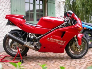
Ducati 888STRADA, 888S.P.O., 888S.P.5. 1991-1994 Workshop Repair Service Manual BEST DOWNLOAD

Ducati 888 1991-1994

MDCT8889194OPMS.PDF
Price: $9.99 USD

Ducati 888STRADA, 888S.P.O., 888S.P.5. 1991-1994 Workshop Repair Service Manual

This highly detailed Manual for your Ducati 888STRADA, 888S.P.O., 888S.P.5. 1991-1994 contains everything you will ever need to repair, maintain, rebuild, refurbish or restore your vehicle. All diagnostic and repair procedures are covered in great detail.

This QUALITY manual is 100 percents COMPLETE and INTACT, no MISSING/CORRUPT pages/sections to freak you out! Buy from responsible seller and get INSTANT DOWNLOAD now without wasting your hard-owned money on uncertainty or surprise; this manual is exactly as described. This Digital Workshop Repair Manual covers the same information that Professional Technicians and Mechanics have. You can view and print out the complete repair procedures with this easy to use this Digital Workshop Repair Manual – you do not need to be skilled with a computer! Once you have found your information, just print it out and start work. No more messy manuals that you have to keep replacing or cant use any more due to wear and tear.

All Repair Procedures Covered From A-Z
High Quality Photos, Illustrations And Diagrams
Buy From A Trusted Seller, Selling Genuine Items

SERVICE MANUAL DETAILS:
1. Downloadable: YES
2. Requirements: PDF Reader
3. FileTYPE: PDF
4. Compatibility: All Versions of Windows & Mac & Linux

PRODUCT DETAILS:
PAGES / SIZE: 393 Pages
FORMAT: PDF
OS: Windows XP/vista/7/8/Linux/Mac

MAKE: Ducati
MODEL: 888STRADA, 888S.P.O., 888S.P.5.
YEAR: 1991 1992 1993 1994
LANGUAGE: EN/DE/ES/FR/IT

EXCERPTS:
Rear fairing disassembly (STRADA)
Remove the passenger seat (A) by operating the rear locking (B). (lilt tie front part to free it from the guide pins and then slide it to the rear).
Unscrew the 4 screws (I) laterally securing the sides to the frame; remove the sides, extracting them from the rear positioning pins.
Unloose the screw of the ride seal and extract it from the frame tubes.

Air filter and suction box disassembly and throttle body disconnection from the motor.
Remove the filter cover and the cartridge after having unhooked the hooks fastening them to the suction box.
Using a screwdriver with a 4mm hexagonal internal head, unscrew the two screws (1) that secure the feed spout of the horizontal cylinder to the filter box and remove the spout.
Unscrew the two screws (2) which fasten the air feeding of the vertical cylinder and remove it.
Loose the damp and disconnect the pipe (3) connected to the breather tank.


MDCT8889194OPMS.PDF
Price: $9.99 USD