Posted on

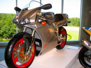
Ducati 848 Motorcycle 2008 Workshop Repair & Service Manual [774 Pages, COMPLETE & INFORMATIVE for DIY REPAIR] ☆ ☆ ☆ ☆ ☆

Ducati 848 Motorcycle 2008 Workshop Repair & Service Manual [774 Pages, COMPLETE & INFORMATIVE for DIY REPAIR]

MDCT84808OPES.PDF
Price: $9.99 USD

Ducati 848 Motorcycle 2008 Workshop Repair & Service Manual [774 Pages, COMPLETE & INFORMATIVE for DIY REPAIR] ☆ ☆ ☆ ☆ ☆

* COMPLETE, Absolutely No Missing Pages!
* Official Service INFORMATION You Can Count On!
* Customer Satisfaction GUARANTEED!

This high QUALITY official manual for Ducati 848 Motorcycle 2008 is 100 percents COMPLETE and INTACT, no MISSING, CORRUPT pages, sections to freak you out! This manual is exactly as described. It is in the cross-platform PDF document format so that it works like a charm on all kinds of devices.

FORMAT: PDF
LANGUAGE: English
OS: Windows/Mac/Linux

INSTANT DELIVERY: A download link will be sent to you instantly after payment. Simply click on the link and save it to your computer. You can use this Manual as long as you wish with no restrictions.

CUSTOMER SATISFACTION: If there is ANY kind of problem with the item you purchased, just drop a quick email. Within HOURS the issue shall be taken care of.

PRINTABLE MANUAL WITH DIAGRAMS: Just print the manual out and start to work. You can also use the manual with your Tablet/Laptop in your garage.

REFUND/EXCHANGE POLICY: We sell high QUALITY products only. However if you encounter any problems with the item you purchased, another replacement link will be sent to you. If we’re at fault, you will get 100 percents refund.

Buy ☆THE BEST MANUAL ON THE INTERNET☆ from responsible seller and get instant download now without uncertainty or surprise.

This highly detailed workshop service repair manual for download contains virtually everything you will ever need to repair, maintain, rebuild, refurbish or restore Your Ducati 848 Motorcycle 2008 (ALL MODELS ARE COVERED). All diagnostic and repair procedures and gives you access to the same information that professional technicians and mechanics have. You can view and print out the complete repair procedures with this workshop service repair manual Download – you do not need to be skilled with a computer.

EXCERPTS:
0A – General
0B – Information about the model
0C – Technical data
0D – Use and maintenance
0E – Fairings
0F – Controls – Devices
0G – Wheels – Suspension – Brakes
0H – Frame
0L – Fuel/Exhaust System
0M – Fuel injection – ignition system
0N – Engine
0P – Electrical system
0GENERAL SUMMARY

Overhauling the wheel
Inspect the wheel as follows:
Visually inspect the wheel for cracks, scoring and deformation; change the wheel if damaged.
Fit the wheel on service tool no. 88713.2951 using the original fasteners.
Using a dial gauge, measure rim run-out and out-of-round relative to the wheel axle (see Sect. C 1.1, Rear wheel).
If the values measured are not within the tolerance limits, renew the wheel.
Refitting the rear wheel
Clean the mating surfaces and grease the threaded end of the stub axle with the recommended grease.
Fit the wheel, aligning it with the stub axle and the driving pins.
Fit the tapered bush (3) and the washer (2), and hand tighten the wheel nut (1).
Tighten the wheel nut (1) to the specified torque (Sect. C 3, Frame torque settings) and check that the hole in the nut is aligned with one of the holes in the stub axle.
If not, tighten the nut slightly to bring the holes into alignment.
Fit the circlip (6).

Removal of the evaporative emissions canister
Before removing the canister (1) it is first necessary to remove the fairings (Sect. E 2, Removal of the side fairings) and raise the fuel tank (Sect. L 2, Removal of the fuel tank).
Disconnect the hose (4), removing the clip (11).
Remove the clips (7) and (5) and withdraw the canister filter (1) upwards along the guides of the plate (17).
To remove the hoses which deliver fuel to the intake manifolds, first remove the clips (7) and withdraw the hoses (9) and (11).

3 – System components
Electronic Control Unit (ECU)
The engine ECU (1) is an electronic digital microprocessor-based unit.
It controls both the injectors and the coils, thus controlling fuel injection and ignition in accordance with the engine operating conditions detected by the following sensors:
– Absolute pressure sensor (measures atmospheric pressure)
– Air temperature sensor (measures intake air temperature)
– Engine temperature sensor (measures coolant temperature)
– Timing/rpm sensor (measures engine rotation speed and cylinder timing relative to TDC)
– Throttle position sensor (measures the throttle opening angle).
The ECU also monitors battery voltage so that it can adjust injector opening time and ignition coil charging time accordingly.
The ECU determines the following values:
– Amount of fuel delivered to each cylinder with a sequential non-parallel control
– Injector closing time and therefore injection timing relative to the end of the induction stroke for each cylinder
– Ignition advance.
Important
The maps, which include ignition advance values, injection times, crankshaft angle for injector closing and all correction curves as a function of temperature and atmospheric pressure values, are stored in the Flash Eprom of the ECU. The above values are preset by the Manufacturer after testing the motorcycle under different riding conditions. These settings cannot be changed.
CO content can be adjusted using software on the “DDS” tester, which should be connected to the ECU
diagnostic socket.
For this procedure, refer to Sect. D 5, Adjusting the idle speed.
There are two types of ECU connector, one has a grey terminal block (Telaio-Body), and one has a
black terminal block (Motore-Engine).


MDCT84808OPES.PDF
Price: $9.99 USD

Posted on

Ducati 750-900 1985-1996 Workshop Repair & Service Manual (COMPLETE & INFORMATIVE for DIY REPAIR) ☆ ☆ ☆ ☆ ☆

Ducati 750-900 1985-1996 Workshop Repair & Service Manual (COMPLETE & INFORMATIVE for DIY REPAIR) ☆ ☆ ☆ ☆ ☆

MDCT7508596OPMK.PDF
Price: $9.99 USD

Ducati 750-900 1985-1996 Workshop Repair & Service Manual (COMPLETE & INFORMATIVE for DIY REPAIR) ☆ ☆ ☆ ☆ ☆

* COMPLETE, Absolutely No Missing Pages!
* Official Service INFORMATION You Can Count On!
* Customer Satisfaction GUARANTEED!

This high QUALITY official manual for 1985-1996 Ducati 750-900 (F1/Montjuich/Sport/S.S.) is 100 percents COMPLETE and INTACT, no MISSING, CORRUPT pages, sections to freak you out! This manual is exactly as described. It is in the cross-platform PDF document format so that it works like a charm on all kinds of devices.

FORMAT: PDF
SIZE/PAGE: 105 MB
OS: Windows/Mac OS X/Linux/Android/iOS
YEAR: 1991 1992 1993 1994 1995 1996
LANGUAGE: EN/DE/ES/FR/IT

’85-’88 750 F1/Montjuich Parts Catalog.pdf
’85-’88 750 F1/Montjuich.pdf
’88-’90 750 Sport.pdf
’91-’96 750S.S., 900S.S.pdf

INSTANT DELIVERY: A download link will be sent to you instantly after payment. Simply click on the link and save it to your computer. You can use this Manual as long as you wish with no restrictions.

CUSTOMER SATISFACTION: If there is ANY kind of problem with the item you purchased, just drop a quick email. Within HOURS the issue shall be taken care of.

PRINTABLE MANUAL WITH DIAGRAMS: Just print the manual out and start to work. You can also use the manual with your Tablet/Laptop in your garage.

REFUND/EXCHANGE POLICY: We sell high QUALITY products only. However if you encounter any problems with the item you purchased, another replacement link will be sent to you. If we’re at fault, you will get 100 percents refund.

Buy ☆THE BEST MANUAL ON THE INTERNET☆ from responsible seller and get instant download now without uncertainty or surprise.

This highly detailed workshop service repair manual for download contains virtually everything you will ever need to repair, maintain, rebuild, refurbish or restore 1985-1996 Ducati 750-900 (F1/Montjuich/Sport/S.S.) Motorbike. All diagnostic and repair procedures and gives you access to the same information that professional technicians and mechanics have. You can view and print out the complete repair procedures with this workshop service repair manual Download – you do not need to be skilled with a computer.

EXTRACTS:
Changing engine speeds.
The illustration below shows the variation in ideal air-fuel ratios as engine speeds change. The ratios are expressed in terms of weight. A 15:1 ratio, for example, represents 15 grams of air to one gram of fuel.
At idle, or during low-speed operation, the amount of the air-fuel mixture taken into the combustion chamber is small, and the speed at which the mixture enters the combustion chamber is relatively slow. These two factors prevent complete mixing of the air and fuel, and allow a high percentage of the burned exhaust gases to remain, causing a dilution of the total intake charge. When this happens, additional fuel must be supplied to assist the mixture in igniting properly.
During midrange, no-load operation, the air-fuel ratio can meet, or even exceed, the ideal 15:1 ratio. Under these ideal conditions, an engine can achieve maximum economy and efficiency. This clearly explains why gas mileage increases dramatically
during highway cruising, and why HC and CO readings drop approximately 50% during the midrange test with exhaust gas analyzer.
At high speeds, richer air-fuel mixtures are also required to prevent overheating, to compensate for the decrease in intake duration, and to efficiently use all the available air.

SOSPENSIONI E RUOTE
SUSPENSIONS AND WHEELS
SUSPENSIONS ET ROUES
AUFHÄNGUNGEN UND RÄDER
SUSPENSIONES Y RUEDAS

Sostituzione cuscinetti di sterzo.
Dovendo sostituire i cuscinetti del cannotto di sterzo procedere nel modo seguente:
– Svitare completamente la vite {1 );
– Allentare le viti (2) sui morsetti di tenuta delle canne alla lesta di sterzo;
– Allentare la vite (3) sulla testa di sterzo.
Con l’ausilio di un martello di gomma sfilare la testo di sterzo dalle canne e dal perno.
Svitare completamente lo ghiera (4) e rimuoverlo.
Sfilare dalla parte inferiore il perno dal cannotto.
Steering bearings replacement.
When replacing the steering liner bearings proceed as follows:
– completely unscrew the screw ( 1 );
– unloose the screws |2) on the liners clamping terminals to the steering head,
– unloose the screw (3) on the steering head
With o rubber hammer, extract the steering head from liners and pin
Completely unscrew the ring nut (4) and remove it.
Extract the liner pin from the lower side.
Remplacement coussinets de direction.
Pour le remplacement des coussinets du canot de direction, procéder de la façon suivante:
– Désserrer complètement la vis f 1 );
– Désserrer les vis (2) sur les étaux qui fixent les tuyaux à la tête de direction;
– Désserrer la vis (3) sur lo tête de direction.
Au moyen d’un marteau en caoutchouc, extraire la tête de direction des tuyaux et du pivot.
Extraire complètement l’embout (4) et l’enlever.
Extraire le pivot du canot de lo partie inférieure.
Austausch der Steuergetriebelager.
Beim Austausch der Lager des Steuergelrieberohrs, gehl man wie folgt vor:
– Die Schraube ( 1 ) ganz ausschrauben;
– Die Schrauben (2) auf die Klemmen lösen, welche dem Lenkungskopf die Buchsen
befestigen;
– Die Schraube (3) auf dem Lenkungskopf lösen.
Mil einem Gummihammer, den Lenkungskopf von den Buchsen und Bolzen ausziehen.
Die Nutmutter (4) ganz ausschrauben und sie beseitigen.Vom unteren Teil, den Bolzen
vom Rohr ausziehen.
Sustitución cojinetes de dirección.
Para sustituir los cojinetes de la columna de dirección proceder de la manera siguiente:
– Desatornillar completamente el tornillo ( 1 );
– Aflojar los tornillos (2) situados en los bornes de retención de las caños con la cabeza
de dirección;
– Aflojar el tornillo (3) situado en la cabeza de dirección.
Con la ayuda de un martillo de goma sacar la cabeza de dirección de las cañas y
del perno
Desenroscar completamente la virola (4) y quitarla.
Sacar el perno de la columna por la parte inferior


MDCT7508596OPMK.PDF
Price: $9.99 USD

Posted on

Ducati 748-916 (STR-SP-BIP-S) 1994-2002 Workshop Repair & Service Manual (COMPLETE & INFORMATIVE for DIY REPAIR) ☆ ☆ ☆ ☆ ☆

Ducati 748-916 (STR-SP-BIP-S) 1994-2002 Workshop Repair & Service Manual (COMPLETE & INFORMATIVE for DIY REPAIR)

Ducati 748-916 (STR-SP-BIP-S) 1994-2002 Workshop Repair & Service Manual (COMPLETE & INFORMATIVE for DIY REPAIR) ☆ ☆ ☆ ☆ ☆


MDCTMISC9402OPMK.PDF
Price: $9.99 USD

* COMPLETE, Absolutely No Missing Pages!
* Official Service INFORMATION You Can Count On!
* Customer Satisfaction GUARANTEED!

This high QUALITY official manual for Ducati 748-916 (STR-SP-BIP-S) 1994-2002 is 100 percents COMPLETE and INTACT, no MISSING, CORRUPT pages, sections to freak you out! This manual is exactly as described. It is in the cross-platform PDF document format so that it works like a charm on all kinds of devices.

FORMAT: PDF
LANGUAGE: English (EN), Italian, (IT), German (DE), French (FR), Spanish (ES)
SIZE/PAGE: 484 Pages
OS: Windows/Mac OS X/Linux/Android/iOS

MAKE: Ducati
YEAR: 1994 1995 1996 1997 1998 1999 2000 2001 2002
MODEL:
748 Monoposto Strada (748 STR.)
748 Sport Production (748 S.P.)
748 Biposto (748 BIP.)
916 Monoposto Strada (916 STR.)
916 Senna (916 S)
916 Sport Production (916 S.P.)
916 Biposto (916 BIP.)

INSTANT DELIVERY: A download link will be sent to you instantly after payment. Simply click on the link and save it to your computer. You can use this Manual as long as you wish with no restrictions.

CUSTOMER SATISFACTION: If there is ANY kind of problem with the item you purchased, just drop a quick email. Within HOURS the issue shall be taken care of.

PRINTABLE MANUAL WITH DIAGRAMS: Just print the manual out and start to work. You can also use the manual with your Tablet/Laptop in your garage.

REFUND/EXCHANGE POLICY: We sell high QUALITY products only. However if you encounter any problems with the item you purchased, another replacement link will be sent to you. If we’re at fault, you will get 100 percents refund.

Buy ☆THE BEST MANUAL ON THE INTERNET☆ from responsible seller and get instant download now without uncertainty or surprise.

This highly detailed workshop service repair manual for download contains virtually everything you will ever need to repair, maintain, rebuild, refurbish or restore Ducati 748-916 (STR-SP-BIP-S) 1994-2002. All diagnostic and repair procedures and gives you access to the same information that professional technicians and mechanics have. You can view and print out the complete repair procedures with this workshop service repair manual Download – you do not need to be skilled with a computer.

EXTRACTS:

Extract control red and clutch plates.
Hold dutch drum steady using tool no. 88713.0146 and undo lock nut.
Remove knurled washer. bush ond pilot pin, O ring ond thrust washer.
Slide drum and push drive hub off clutch shalt.
If the rubber dampers (I) need replacement, use a press to overcome the resistance offered by rubber dampers and Extract hub from clutch drum 121.

Undo the eight screws that secure clutch housing to primary drive gear. While carrying out this operation, hold dutch housing still with tool no. 88713.0146.
Extract clutch housing.
Loosen and remove the eight screws that fasten R.H. cover.
Remove cover and gasket.
Remove locating bush and the O ring located near the oil drilling from the half crankcase.
Remove spacer, pulling it strongly outwards to overcome the resistance of the O ring fitted on it.


MDCTMISC9402OPMK.PDF
Price: $9.99 USD

Posted on

Dodge Viper 2005 Workshop Repair & Service Manual (COMPLETE & INFORMATIVE for DIY REPAIR) ☆ ☆ ☆ ☆ ☆

Dodge Viper 2005 Workshop Repair & Service Manual (COMPLETE & INFORMATIVE for DIY REPAIR)

MDGVP05OPES.PDF
Price: $9.99 USD

Dodge Viper 2005 Workshop Repair & Service Manual (COMPLETE & INFORMATIVE for DIY REPAIR) ☆ ☆ ☆ ☆ ☆

* COMPLETE, Absolutely No Missing Pages!
* Official Service INFORMATION You Can Count On!
* Customer Satisfaction GUARANTEED!

This high QUALITY official manual for Dodge Viper 2005 is 100 percents COMPLETE and INTACT, no MISSING, CORRUPT pages, sections to freak you out! This manual is exactly as described. It is in the cross-platform PDF document format so that it works like a charm on all kinds of devices.

FORMAT: PDF
LANGUAGE: English
SIZE/PAGE: 1,056 Pages
OS: Windows/Mac OS X/Linux/Android/iOS

MAKE: Dodge
MODEL: ZB Viper (a.k.a. SRT-10)
YEAR: 2005

INSTANT DELIVERY: A download link will be sent to you instantly after payment. Simply click on the link and save it to your computer. You can use this Manual as long as you wish with no restrictions.

CUSTOMER SATISFACTION: If there is ANY kind of problem with the item you purchased, just drop a quick email. Within HOURS the issue shall be taken care of.

PRINTABLE MANUAL WITH DIAGRAMS: Just print the manual out and start to work. You can also use the manual with your Tablet/Laptop in your garage.

REFUND/EXCHANGE POLICY: We sell high QUALITY products only. However if you encounter any problems with the item you purchased, another replacement link will be sent to you. If we’re at fault, you will get 100 percents refund.

Buy ☆THE BEST MANUAL ON THE INTERNET☆ from responsible seller and get instant download now without uncertainty or surprise.

This highly detailed workshop service repair manual for download contains virtually everything you will ever need to repair, maintain, rebuild, refurbish or restore Dodge Viper 2005. All diagnostic and repair procedures and gives you access to the same information that professional technicians and mechanics have. You can view and print out the complete repair procedures with this workshop service repair manual Download – you do not need to be skilled with a computer.

GROUP TAB LOCATOR
Introduction
0 Lubrication & Maintenance
2 Suspension
3 Differential & Driveline
5 Brakes
6 Clutch
7 Cooling
8A Audio/Video
8B Chime/Buzzer
8E Electronic Control Modules
8F Engine Systems
8G Heated Systems
8H Horn
8I Ignition Control
8J Instrument Cluster
8L Lamps
8N Power Systems
😯 Restraints
8Q Vehicle Theft Security
8R Wipers/Washers
8W Wiring
9 Engine
11 Exhaust System
13 Frame & Bumpers
14 Fuel System
19 Steering
21 Transmission/Transaxle
22 Tires/Wheels
23 Body
24 Heating & Air Conditioning
25 Emissions Control
Component and System Index
Service Manual Comment Forms (Rear of Manual)

WHEEL MOUNTING STUDS –
FRONT
REMOVAL
NOTE: Review all Warnings and Cautions. (Refer to 2 – SUSPENSION – WARNING)
CAUTION: If a wheel mounting stud needs to be replaced in the hub and bearing assembly, DO NOT hammer it out of the hub flange. If a stud is removed by hammering it out of the bearing flange, damage to the hub and bearing assembly can occur, leading to premature bearing failure. Please use the following procedure.
(1) Remove the front hub and bearing assembly. (Refer to 2 – SUSPENSION/FRONT/HUB / BEARING – REMOVAL)
(2) If possible, install a standard type wheel mounting nut on the wheel stud to be removed just far enough so the threads on the outer end of the nut are even with outer end of the stud (Fig. 27).
(3) Install Remover, Special Tool C-4150A, on the hub/bearing flange and wheel stud as shown (Fig. 27).
(4) Tighten down the special tool bolt; this will push the wheel stud out of the hub flange. Remove the tool, nut and stud.

WASHER PUMP MOTOR REMOVAL
(1) Disconnect and isolate the battery negative cable.
(2) Remove the washer reservoir (Refer to 8 – ELECTRICAL/WIPERS/WASHERS/WASHER RESERVOIR – REMOVAL).
(3) Disconnect wire harness connector and washer hose.
(4) Remove washer pump.
INSTALLATION
(1) Install pump to reservoir.
(2) Connect wire harness connector and washer hose.
(3) Install washer reservoir (Refer to 8 – ELECTRICAL/ WIPERS/WASHERS/WASHER RESERVOIR – INSTALLATION).
(4) Connect battery negative cable.

A/C CLUTCH BREAK-IN
After a new A/C compressor clutch has been
installed, cycle the compressor clutch approximately twenty times (five seconds on, then five seconds off).
During this procedure, set the A/C-heater controls to the A/C Recirculation Mode, the blower motor in the highest speed position, and the engine speed at 1500 to 2000 rpm. This procedure (burnishing) will seat the opposing friction surfaces and provide a higher compressor clutch torque capability.
REMOVAL
NOTE: The compressor clutch can be serviced in the vehicle. The refrigerant system can remain fully charged during compressor clutch, pulley, or coil replacement.
(1) Disconnect and isolate the negative battery
cable.
(2) Remove the accessory drive belt (Refer to 7 – COOLING/ACCESSORY DRIVE/DRIVE BELTS – REMOVAL).
(3) Raise and support the vehicle.
(4) Disconnect the engine wire harness connector for the compressor clutch coil from the clutch coil pigtail wire connector on the top of the A/C compressor.
(5) Remove the bolts that secure the A/C compressor to the engine and support the A/C compressor.
(6) Remove the compressor shaft bolt (Fig. 3). A band-type oil filter wrench or a strap wrench may be used to secure the clutch during bolt removal.
(7) Tap the clutch plate lightly with a plastic mallet to release it from the splines on the compressor shaft. Remove the clutch plate and shim(s) from the
compressor shaft (Fig. 4).
NOTE: Use care not to lose any of the shim(s).
CAUTION: Do not pry between the clutch plate unit and the pulley to remove the clutch plate from the compressor shaft as this may damage the clutch plate.
(8) Using snap ring pliers (Special Tool C-4574 or equivalent), remove the external snap ring that secures the pulley to the front cover of the compressor, then slide the pulley off of the compressor (Fig. 5).
(9) Remove the screw that secures the clutch coil pigtail wire connector bracket and ground clip to the top of the compressor housing.


MDGVP05OPES.PDF
Price: $9.99 USD