Posted on

Caterpillar C0.5, C0.7, C1.1/3011C, C1.5/3013C, C1.6 & C2.2/3024C/3024CT Engines Factory Service & Shop Manual


Download Link

INSTANT DOWNLOAD (add to cart)


Complete workshop & service manual with electrical wiring diagrams for Caterpillar C0.5, C0.7, C1.1/3011C, C1.5/3013C, C1.6 & C2.2/3024C/3024CT Industrial Engines & Engines for Caterpillar Built Machines. It’s the same service manual used by dealers that guaranteed to be fully functional and intact without any missing page.

This Caterpillar C0.5, C0.7, C1.1/3011C, C1.5/3013C, C1.6 & C2.2/3024C/3024CT Industrial Engines & Engines for Caterpillar Built Machines service & repair manual (including maintenance, overhaul, disassembling & assembling, adjustment, tune-up, operation, inspecting, diagnostic & troubleshooting…) is divided into different sections. Each section covers a specific component or system with detailed illustrations. A table of contents is placed at the beginning of each section. Pages are easily found by category, and each page is expandable for great detail. The printer-ready PDF documents work like a charm on all kinds of devices.

MANUAL LIST:
RENR2422 – Specifications (C0.5, C0.7, C1.1/3011C, C1.5/3013C, C1.6 & C2.2/3024C/3024CT Industrial Engines & Engines for Caterpillar Built Machines)
RENR2423 – Systems Operation (C0.5, C0.7, C1.1/3011C, C1.5/3013C, C1.6 & C2.2/3024C/3024CT Industrial Engines & Engines for Caterpillar Built Machines)
RENR2424 – Disassembly & Assembly (C0.5, C0.7, C1.1/3011C, C1.5/3013C, C1.6 & C2.2/3024C/3024CT Industrial Engines & Engines for Caterpillar Built Machines)
SENR5004 – Specifications (3024C Engine for Caterpillar Built Machines)
SENR5005 – Systems Operation (3024C & C1.1 Engines for Caterpillar Built Machines)
SENR5005 – Testing & Adjusting (3024C & C1.1 Engines for Caterpillar Built Machines)
SENR5006 – Disassembly & Assembly (3024C Engine for Caterpillar Built Machines)
RENR2423 – Troubleshooting (C0.5, C0.7, C1.1/3011C, C1.5/3013C, C1.6 & C2.2/3024C/3024CT Industrial Engines & Engines for Caterpillar Built Machines).pdf
KENR6948 – Disassembly & Assembly (C1.5 & C2.2 Engines for Caterpillar Built Machines)

EXCERPT:
4. Place camshaft retainer (5) in position. Align the holes in the retainer with the holes in the cylinder block.
5. Rotate camshaft gear (4) to align the access hole in the camshaft gear with the hole for fastener (2).
Install bolt (2) and tighten to a torque of 10 N·m (89 lb in). Rotate camshaft gear (4) to align the access hole in the camshaft gear with the hole for bolt (1). Install bolt (1) and tighten to a torque of 10 N·m (89 lb in).
6. Install slider (3) to camshaft gear (4).
7. If the engine is equipped with a mechanical fuel transfer pump, install the fuel transfer pump.
Refer to Disassembly and Assembly, “Fuel Transfer Pump – Remove and Install”.
End By:
a. Install the lifters. Refer to Disassembly and Assembly, “Lifter Group- Remove and Install”.
b. Install the front housing. Refer to Disassembly and Assembly, “Housing (Front) – Install”.

Posted on

Caterpillar 3508C/3512C/3516C Engines Factory Service & Shop Manual + Parts Manual


Download Link

INSTANT DOWNLOAD (add to cart)


Complete workshop & service manual with electrical wiring diagrams for Caterpillar 3508C/3512C/3516C Generator Set / Industrial / Machine / Marine / Petroleum Engines. It’s the same service manual used by dealers that guaranteed to be fully functional and intact without any missing page.

This Caterpillar 3508C/3512C/3516C Generator Set / Industrial / Machine / Marine / Petroleum Engines service & repair manual (including maintenance, overhaul, disassembling & assembling, adjustment, tune-up, operation, inspecting, diagnostic & troubleshooting…) is divided into different sections. Each section covers a specific component or system with detailed illustrations. A table of contents is placed at the beginning of each section. Pages are easily found by category, and each page is expandable for great detail. The printer-ready PDF documents work like a charm on all kinds of devices.

MANUAL LIST:
SEBP4364 – Parts Manual (3512C Engine).pdf
KENR5402 – Specifications (3500C Marine Engines)
KENR5403 – Systems Operation (3500 Marine Engines)
KENR5403 – Testing & Adjusting (3500 Marine Engines)
KENR5405 – Troubleshooting (3500C Marine Auxiliary Engines)
KENR6055 – Disassembly & Assembly (3508C, 3512C, 3516C Marine Engines)
UENR4397 – Testing & Adjusting (3516C High Displacement Industrial Engine)
UENR0576 – Specifications (3516C Petroleum Engines)
UENR0577 – Systems Operation (3516C HD Petroleum Well Service Engines)
UENR0577 – Testing & Adjusting (3516C HD Petroleum Well Service Engines)
UENR0578 – Troubleshooting (3516C HD Petroleum Well Service Engines)
UENR2650 – Schematic (3516C Well Fracturing Engine Electrical System)
UENR3273 – Disassembly & Assembly (3516C Petroleum Engines)
UENR4397 – Systems Operation (3516C High Displacement Industrial Engine)
KENR5415 – Specifications (3512C & 3516C Industrial Engines)

EXCERPT:
Illustration 7
6. Use Tooling (E) and a suitable press to install rotating seal group (6). Rotating seal group (6) is to be installed with installation clips (X) in place until rotating seal group (6) is fully seated. Remove installation clips (X).
Note: Do not use hammer to install seal groups as damage to the ceramic faces on the seal groups will occur.
Illustration 8

7. Lubricate the shaft assembly with a light coat of engine oil. Use a suitable press to install impeller (5) into pump housing (10) and onto the shaft assembly. Install impeller (5) to a depth of 0.0 ± 0.15 mm (0.00000 ± 0.00591 inch) from the end of the shaft assembly to the outer face of the impeller.

Posted on

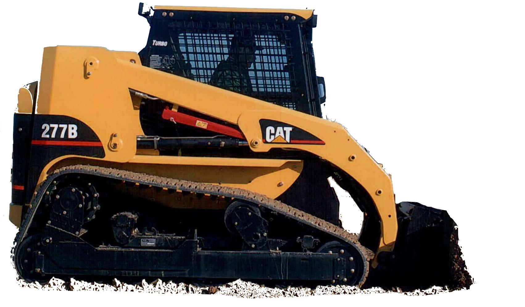
Caterpillar 267B, 277B, 287B Multi Terrain Loaders Factory Service & Shop Manual


Download Link

INSTANT DOWNLOAD (add to cart)


Complete workshop & service manual with electrical wiring diagrams for Caterpillar 267B, 277B, 287B Multi Terrain Loaders. It’s the same service manual used by dealers that guaranteed to be fully functional and intact without any missing page.

This Caterpillar 267B, 277B, 287B Multi Terrain Loaders service & repair manual (including maintenance, overhaul, disassembling & assembling, adjustment, tune-up, operation, inspecting, diagnostic & troubleshooting…) is divided into different sections. Each section covers a specific component or system with detailed illustrations. A table of contents is placed at the beginning of each section. Pages are easily found by category, and each page is expandable for great detail. The printer-ready PDF documents work like a charm on all kinds of devices.

MANUAL LIST:
RENR4883 – Disassembly & Assembly (267B, 277B, 287B Multi Terrain Loaders Engine Supplement)
RENR4884 – Disassembly & Assembly (267B, 277B & 287B Multi Terrain Loaders Power Train)
RENR4885 – Specifications (267B, 277B & 287B Multi Terrain Loaders Machine Systems)
RENR4886 – Systems Operation (267B, 277B & 287B Multi Terrain Loaders Machine Systems)
RENR4887 – Testing & Adjusting (267B, 277B & 287B Multi Terrain Loaders Machine Systems)
RENR4888 – Disassembly & Assembly (267B, 277B & 287B Multi Terrain Loaders Machine Systems)
RENR4889 – Schematic (247B, 247B2, 257B, 257B2, 267B, 277B, 287B Multi Terrain Loaders Hydraulic System)
RENR6417 – Systems Operation (247B, 257B, 267B, 277B & 287B Multi Terrain Loaders & 216B, 226B, 232B, 236B, 242B, 246B, 248B, 252B, 262B & 268B Skid Steer Loaders Interlock Electronic Control System)
RENR6417 – Testing & Adjusting (247B, 257B, 267B, 277B & 287B Multi Terrain Loaders & 216B, 226B, 232B, 236B, 242B, 246B, 248B, 252B, 262B & 268B Skid Steer Loaders Interlock Electronic Control System)
RENR6417 – Troubleshooting (247B, 257B, 267B, 277B & 287B Multi Terrain Loaders & 216B, 226B, 232B, 236B, 242B, 246B, 248B, 252B, 262B & 268B Skid Steer Loaders Interlock Electronic Control System)
RENR6418 – Systems Operation (247B, 257B, 267B, 277B, 287B Multi Terrain Loaders and 216B, 226B, 232B, 236B, 242B, 246B, 248B, 252B, 262B, 268B Skid Steer Loaders Auxiliary Hydraulic Electronic Control System)
RENR6418 – Testing & Adjusting (247B, 257B, 267B, 277B, 287B Multi Terrain Loaders and 216B, 226B, 232B, 236B, 242B, 246B, 248B, 252B, 262B, 268B Skid Steer Loaders Auxiliary Hydraulic Electronic Control System)
RENR6418 – Troubleshooting (247B, 257B, 267B, 277B, 287B Multi Terrain Loaders and 216B, 226B, 232B, 236B, 242B, 246B, 248B, 252B, 262B, 268B Skid Steer Loaders Auxiliary Hydraulic Electronic Control System)
RENR6419 – Schematic (Skid Steer Loaders_216B, 216B2, 226B, 226B2, 232B, 232B2, 236B, 236B2, 242B, 242B2, 246B, 248B, 252B, 252B2, 262B, 268B & Multi Terrain Loaders_247B, 247B2, 257B, 257B2, 267B, 277B, 287B Electrical System)
RENR8749 – Schematic (248B and 268B Skid Steer Loader 287B Multi Terrain Loader Hydraulic System)
RENR8751 – Schematic (247B, 247B2, 257B, 257B2, 267B, 277B, 287B Multi-Terrain Loader Hydraulic System)

EXCERPT:
3. spring (5) . Remove fitting (6).
Illustration 4
Typical Example
4. Install Tooling (H) . Use low pressure compressed air to remove piston (7) .
Note: Low-pressure air is required in order to allow the piston to release from the motor.
Note: Tooling (H) is required in order to prevent damage to the piston.
5. Remove O-ring seal (8) .

Posted on

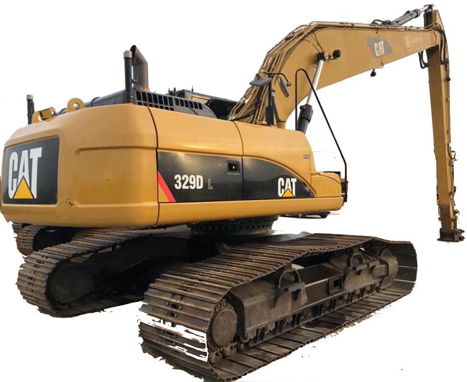
Caterpillar 324D, 325D, 326D, 329D & 329D MHPU Mobile Hydraulic Power Unit Factory Service & Shop Manual


Download Link

INSTANT DOWNLOAD (add to cart)


Complete workshop & service manual with electrical wiring diagrams for Caterpillar 324D, 325D, 326D, 329D & 329D MHPU Mobile Hydraulic Power Unit. It’s the same service manual used by dealers that guaranteed to be fully functional and intact without any missing page.

This Caterpillar 324D, 325D, 326D, 329D & 329D MHPU Mobile Hydraulic Power Unit service & repair manual (including maintenance, overhaul, disassembling & assembling, adjustment, tune-up, operation, inspecting, diagnostic & troubleshooting…) is divided into different sections. Each section covers a specific component or system with detailed illustrations. A table of contents is placed at the beginning of each section. Pages are easily found by category, and each page is expandable for great detail. The printer-ready PDF documents work like a charm on all kinds of devices.

MANUAL LIST:
KENR6122 – Schematic (320D, 321D, 323D, 324D, 325D, 329D, 330D, 336D, & 336D2 Excavator & 336D MHPU Excavator Hydraulic System – Attachment – Universal Quick Coupler (Interactive) 262-3421-02)
RENR7233 – Specifications (325D & 329D Excavators Machine System)
RENR7234 – Systems Operation (325D & 329D Excavators Hydraulic)
RENR7235 – Testing & Adjusting (325D & 329D Excavators Hydraulic System)
RENR7237 – Schematic (325D & 329D Excavator Hydraulic System – Attachment – System 17 Combined Function)
RENR7238 – Schematic (325D & 329D Excavator Hydraulic System – Attachment – System 16 255-5733-01)
RENR7239 – Schematic (324D, 325D, & 329D Excavator Hydraulic System – Attachment – System 17 Combined Function with Medium Pressure)
RENR7240 – Schematic (325D & 329D Excavator Hydraulic System – Attachment – Stick Lowering Control Valve)
RENR7243 – Schematic (324D, 325D, 325D MHPU, & 329D Excavator Electrical System (Interactive), Chassis & Cab 251-0506-03, Engine 235-9565-01)
RENR7389 – Systems Operation (320D, 320D2, 321D, 323D, 324D, 325D, 328D, 329D, 330D, 336D, 336D2, 340D & 340D2 Excavators Tool Control System)
RENR7389 – Testing & Adjusting (320D, 320D2, 321D, 323D, 324D, 325D, 328D, 329D, 330D, 336D, 336D2, 340D & 340D2 Excavators Tool Control System)
RENR8645 – Disassembly & Assembly (324D, 325D, 326D, 329D Excavators & 329D MHPU Mobile Hydraulic Power Unit C7 Engine Supplement)
RENR8646 – Disassembly & Assembly (324D, 325D, 326D, 329D Excavators & 329D MHPU Mobile Hydraulic Power Unit Machine Systems)

EXCERPT:
1. Lift hood (1). Remove panel (2).
2. Loosen clamp (3) in order to disconnect
3. hose (5). Remove bolts (4). Loosen clamp (6). Remove pipe assembly (7). Remove guard assemblies (8).
Remove clips (9). Disconnect hose assembly (10).
5. Disconnect hose assembly (11).

Posted on

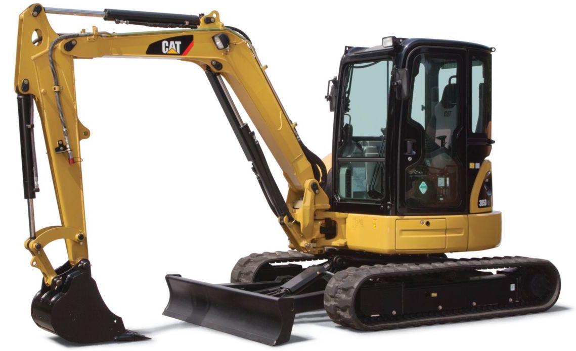
Caterpillar 303.5D CR, 304D CR, 305D CR & 305.5D CR Mini Hydraulic Excavators Factory Service & Shop Manual


Download Link

INSTANT DOWNLOAD (add to cart)


Complete workshop & service manual with electrical wiring diagrams for Caterpillar 303.5D CR, 304D CR, 305D CR & 305.5D CR Mini Hydraulic Excavators. It’s the same service manual used by dealers that guaranteed to be fully functional and intact without any missing page.

This Caterpillar 303.5D CR, 304D CR, 305D CR & 305.5D CR Mini Hydraulic Excavators service & repair manual (including maintenance, overhaul, disassembling & assembling, adjustment, tune-up, operation, inspecting, diagnostic & troubleshooting…) is divided into different sections. Each section covers a specific component or system with detailed illustrations. A table of contents is placed at the beginning of each section. Pages are easily found by category, and each page is expandable for great detail. The printer-ready PDF documents work like a charm on all kinds of devices.

MANUAL LIST:
UENR4045 – Schematic (303C, 303.5C, 303.5D, 303.5E, 304C, 304D, 304E, 305C, 305D, 305E, 305.5D & 305.5E Mini Hydraulic Excavators Air Conditioning)
KENR5853 – Specifications (305D CR & 305.5D CR Mini Hydraulic Excavators Machine System)
KENR5854 – Systems Operation (305D CR and 305.5D CR Mini Hydraulic Excavators Hydraulic System)
KENR5855 – Testing & Adjusting (305.5D CR & 305D CR Mini Hydraulic Excavators Hydraulic System)
KENR5856 – Schematic (305D CR Mini Hex Hydraulic System 344-5283-02)
KENR5859 – Schematic (305D CR & 305.5D CR Mini Hydraulic Excavator Electrical System 343-9184-01)
UENR0101 – Disassembly & Assembly (303.5D, 304D, 305.5D & 305D Mini Hydraulic Excavators Engine Supplement)
UENR0102 – Disassembly & Assembly (303.5D CR, 304D CR, 305D CR & 305.5D CR Mini Hydraulic Excavators Machine Systems)

EXCERPT:
Hydraulic System Pressure – Release
Pressure Release Procedure
The release of hydraulic pressure in an hydraulic circuit is required before service is performed to that hydraulic circuit. Release the pressure in the following hydraulic circuits before any hydraulic lines are disconnected from that hydraulic circuit or hydraulic components are removed.
Boom hydraulic circuit
Stick hydraulic circuit
Bucket hydraulic circuit
Swing hydraulic circuit
Travel hydraulic circuit
Attachment hydraulic circuits (if equipped)
Pilot hydraulic circuit
Return hydraulic circuit
Release Of Hydraulic Pressure From A Single Hydraulic Circuit