Posted on

Caterpillar AP-1000 Asphalt Paver Factory Service & Shop Manual


Download Link

INSTANT DOWNLOAD (add to cart)


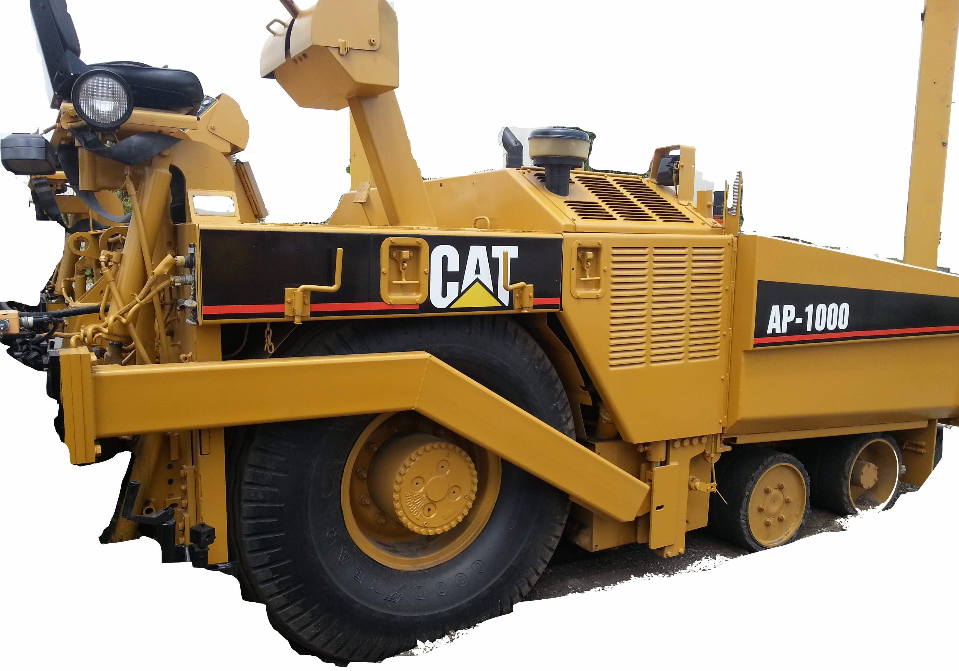
Complete workshop & service manual with electrical wiring diagrams for Caterpillar AP-1000 Asphalt Paver. It’s the same service manual used by dealers that guaranteed to be fully functional and intact without any missing page.

This Caterpillar AP-1000 Asphalt Paver service & repair manual (including maintenance, overhaul, disassembling & assembling, adjustment, tune-up, operation, inspecting, diagnostic & troubleshooting…) is divided into different sections. Each section covers a specific component or system with detailed illustrations. A table of contents is placed at the beginning of each section. Pages are easily found by category, and each page is expandable for great detail. The printer-ready PDF documents work like a charm on all kinds of devices.

MANUAL LIST:
KEBR1232 – Specifications (Asphalt Screeds)
KENR1572 – Specifications (AP-1000 Asphalt Paver Modular Auger Attachment)
KENR1699 – Specifications (AP-800B & AP-1000 Asphalt Pavers Front Wheel Assist Attach)
KENR1846 – Schematic (AP-1000 Asphalt Paver Hydraulic System)
KENR1847 – Disassembly & Assembly (AP-1000 Asphalt Paver Vehicle Systems)
KENR1848 – Schematic (AP-1000 Asphalt Pavers Electrical System)
KENR1849 – Disassembly & Assembly (3116 Engine Supplement for AP-1000 Asphalt Paver)
KENR1853 – Specifications (AP-1000 Asphalt Paver Ground Drive System)
KENR1856 – Specifications (AP-1000 Asphalt Paver Conveyor System)
KENR1857 – Specifications (AP-1000 Asphalt Paver Auxiliary Systems)
KENR1859 – Specifications (AP-1000 Asphalt Paver Vibration System)
KENR1873 – Disassembly & Assembly (AP-1000 Asphalt Paver Power Train)
KENR2526 – Specifications (10-20B Extend-A-Mat Screed)
KENR2527 – Disassembly & Assembly (10-20B Asphalt Screed)
KENR3072 – Specifications (AP-1000 Asphalt Paver Propel System)
KENR3074 – Specifications (AP-1000 Asphalt Paver Conveyor System)
KEBR1231 – Schematic (Asphalt Screeds, Hydraulic System, Fuel Burner System & Elec).pdf
KEBR1232 – Systems Operation (Asphalt Screeds).pdf
KEBR1232 – Testing & Adjusting (Asphalt Screeds).pdf
KENR1572 – System Operation (AP-1000 Asphalt Paver Modular Auger Attachment).pdf
KENR1572 – Testing & Adjusting (AP-1000 Asphalt Paver Modular Auger Attachment).pdf
KENR1699 – System Operation (AP-800B & AP-1000 Asphalt Pavers Front Wheel Assist Attach).pdf
KENR1699 – Testing & Adjusting (AP-800B & AP-1000 Asphalt Pavers Front Wheel Assist Attach).pdf
KENR1854 – Systems Operation (AP-1000 Asphalt Paver Ground Drive System).pdf
KENR1854 – Testing & Adjusting (AP-1000 Asphalt Paver Ground Drive System).pdf
KENR1856 – Systems Operation (AP-1000 Asphalt Paver Conveyor System).pdf
KENR1856 – Testing & Adjusting (AP-1000 Asphalt Paver Conveyor System).pdf
KENR1858 – Systems Operation (AP-1000 Asphalt Paver Auxiliary Systems).pdf
KENR1858 – Testing & Adjusting (AP-1000 Asphalt Paver Auxiliary Systems).pdf
KENR1859 – Systems Operation (AP-1000 Asphalt Paver Vibration System).pdf
KENR1859 – Testing & Adjusting (AP-1000 Asphalt Paver Vibration System).pdf
KENR2526 – Systems Operation (10-20B Extend-A-Mat Screed).pdf
KENR2526 – Testing & Adjusting (10-20B Extend-A-Mat Screed).pdf
KENR3074 – Systems Operation (AP-1000 Asphalt Paver Conveyor System).pdf
KENR3074 – Testing & Adjusting (AP-1000 Asphalt Paver Conveyor System).pdf

EXCERPT:
Conveyor Drive Chain Adjustment
Make reference to WARNING on first page of Testing And Adjusting.
Open top back panels to get to the conveyor drive chain.
Bolt Locations
(1) Right adjusting nut. (2) Right adjusting stud. (3) Right motor mounting frame. (4) Right mounting bolts. (5) Left mounting bolts. (6) Left motor mounting frame. (7) Left adjusting stud. (8) Left adjusting nut. (9) Right drive chain. (10) Left drive chain.
1. Locate the conveyor drive chain adjustment studs under the floor panels at the rear of the tractor near the operator control consoles.
2. To adjust right drive chain (9), loosen right mounting bolts (4) (two are shown to the rear of right torque hub, two more are located forward of the right torque hub).
3. Loosen the right jam nut on right adjusting stud (2). The jam nut is located under the top bracket of right motor mounting frame (3).

Posted on

Caterpillar 950H / 962H Wheel Loader & IT62H Toolcarrier Workshop Repair & Service Manual


Download Link

INSTANT DOWNLOAD (add to cart)


Complete workshop & service manual with electrical wiring diagrams for Caterpillar 950H Wheel Loader, 962H Wheel Loader & IT62H Integrated Toolcarrier. It’s the same service manual used by dealers that guaranteed to be fully functional and intact without any missing page.

This Caterpillar 950H Wheel Loader, 962H Wheel Loader & IT62H Integrated Toolcarrier service & repair manual (including maintenance, overhaul, disassembling & assembling, adjustment, tune-up, operation, inspecting, diagnostic & troubleshooting…) is divided into different sections. Each section covers a specific component or system with detailed illustrations. A table of contents is placed at the beginning of each section. Pages are easily found by category, and each page is expandable for great detail. The printer-ready PDF documents work like a charm on all kinds of devices.

MANUAL LIST:
RENR8863 – Disassembly & Assembly (IT62H Integrated Toolcarrier & 950H & 962H Wheel Loaders C7 Engine Supplement)
RENR8864 – Specifications (950H Wheel Loader, 962H Wheel Loader & IT62H Integrated Toolcarrier Power Train)
RENR8865 – Specifications (950H Wheel Loader, 962H Wheel Loader & IT62H Integrated Toolcarrier Power Train)
RENR8866 – Testing & Adjusting (950H Wheel Loader, 962H Wheel Loader & IT62H Integrated Toolcarrier Power Train)
RENR8866 – Troubleshooting (950H Wheel Loader, 962H Wheel Loader & IT62H Integrated Toolcarrier Power Train)
RENR8867 – Disassembly & Assembly (IT62H Integrated Toolcarrier & 950H & 962H Wheel Loaders Power Train)
RENR8870 – Specifications (950H Wheel Loader, 962H Wheel Loader & IT62H Integrated Toolcarrier Steering System)
RENR8871 – Systems Operation (950H Wheel Loader, 962H Wheel Loader & IT62H Integrated Toolcarrier Steering System)
RENR8872 – Testing & Adjusting (950H Wheel Loader, 962H Wheel Loader & IT62H Integrated Toolcarrier Steering System)
RENR8873 – Specifications (950H Wheel Loader, 962H Wheel Loader & IT62H Integrated Toolcarrier Braking & Hydraulic Fan System)
RENR8874 – Systems Operation (950H Wheel Loader, 962H Wheel Loader & IT62H Integrated Toolcarrier Braking and Hydraulic Fan System)
RENR8875 – Testing & Adjusting (950H Wheel Loader, 962H Wheel Loader & IT62H Integrated Toolcarrier Braking & Hydraulic Fan System)
RENR8876 – Specifications (950H Wheel Loader, 962H Wheel Loader & IT62H Integrated Toolcarrier Electrohydraulic System)
RENR8877 – Systems Operation (950H Wheel Loader, 962H Wheel Loader & IT62H Integrated Toolcarrier Electrohydraulic System)
RENR8878 – Testing & Adjusting (950H Wheel Loader, 962H Wheel Loader & IT62H Integrated Toolcarrier Electrohydraulic System)
RENR8878 – Troubleshooting (950H Wheel Loader, 962H Wheel Loader & IT62H Integrated Toolcarrier Electrohydraulic System)
RENR8879 – Schematic (950H, 962H, and IT62H Wheel Loader Hydraulic System)
RENR8880 – Specifications (950H Wheel Loader, 962H Wheel Loader & IT62H Integrated Toolcarrier Machine Systems)
RENR8881 – Disassembly & Assembly (IT62H Integrated Toolcarrier and 950H & 962H Wheel Loaders Machine Systems)
RENR8882 – Schematic (950H and 962H Wheel Loader IT62H Integrated Toolcarrier Electrical System)

EXCERPT:
17. Remove Tooling (A) from hydraulic tank (1) .
18. Charge the air conditioner system. The correct charge is 2.5 kg (5.5 lb). Refer to Service Manual, SENR5664, “Air Conditioning and Heating Systems with R-134a Refrigerant” for the correct procedure. Refer to Special Publication, NEDG5065, “Air Conditioning Tools” for the correct tools.
19. Refill the cooling system with coolant. Refer to Operation and Maintenance Manual, “Refill Capacities”.
20. Turn the battery disconnect switch to the ON position.
21. Close the engine hood.
End By: Separate the steering frame lock. Refer to Disassembly and Assembly, “Steering Frame
Lock – Separate and Connect”.

Posted on

Caterpillar M325C Material Handler Factory Service & Shop Manual


Download Link

INSTANT DOWNLOAD (add to cart)


Complete workshop & service manual with electrical wiring diagrams for Caterpillar M325C Material Handler. It’s the same service manual used by dealers that guaranteed to be fully functional and intact without any missing page.

This Caterpillar M325C Material Handler service & repair manual (including maintenance, overhaul, disassembling & assembling, adjustment, tune-up, operation, inspecting, diagnostic & troubleshooting…) is divided into different sections. Each section covers a specific component or system with detailed illustrations. A table of contents is placed at the beginning of each section. Pages are easily found by category, and each page is expandable for great detail. The printer-ready PDF documents work like a charm on all kinds of devices.

MANUAL LIST:
RENR7050 – Systems Operation (M325C Material Handler Hydraulic System)
RENR7052 – Specifications (M325C Excavator Machine System)
RENR7053 – Schematic (M325C Material Handler Hydraulic System)
RENR7163 – Disassembly & Assembly (M325C Material Handler Machine Systems)
RENR7164 – Disassembly & Assembly (M325C Material Handler Power Train)
RENR7165 – Disassembly & Assembly (M325C Excavator Engine Supplement)
RENR7852 – Schematic (M325C Material Handler Electrical System)
RENR8064 – Systems Operation (M325C Excavator Power Train Electronic Control System)
RENR8064 – Testing and Adjusting (M325C Excavator Power Train Electronic Control System)
RENR8064 – Troubleshooting (M325C Excavator Power Train Electronic Control System)
RENR9519 – Schematic (M325C Material Handler Magnetic Controller Electrical System)

EXCERPT:
1. Use two people and install ring gear (13). The weight of ring gear (13) is approximately 27 kg (60 lb).
Make sure that the hole in hub (16) is at the bottom. Mark holes (19) for set screw alignment. Apply Tooling (H) to the face of hub (16) .
Illustration 2

Posted on

Caterpillar 980G Wheel Loader Factory Service & Shop Manual


Download Link

INSTANT DOWNLOAD (add to cart)


Complete workshop & service manual with electrical wiring diagrams for Caterpillar 980G Wheel Loader. It’s the same service manual used by dealers that guaranteed to be fully functional and intact without any missing page.

This Caterpillar 980G Wheel Loader service & repair manual (including maintenance, overhaul, disassembling & assembling, adjustment, tune-up, operation, inspecting, diagnostic & troubleshooting…) is divided into different sections. Each section covers a specific component or system with detailed illustrations. A table of contents is placed at the beginning of each section. Pages are easily found by category, and each page is expandable for great detail. The printer-ready PDF documents work like a charm on all kinds of devices.

MANAUL LIST:
UENR7476 – Schematic (980G Wheel Loader Hydraulic System)
RENR4301 – Schematic (980G Wheel Loader Electrical System)
RENR4376 – Schematic (980G Wheel Loader Electrical System)
SENR5873 – Disassembly & Assembly (980G Wheel Loader Engine Supplement)
SENR5874 – Specifications (980G Wheel Loader Power Train)
SENR5875 – Systems Operation (980G Wheel Loader Power Train)
SENR5875 – Testing & Adjusting (980G Wheel Loader Power Train)
SENR5877 – Disassembly & Assembly (980G Wheel Loader Power Train)
SENR5878 – Specifications (980G Wheel Loader Steering System)
SENR5879 – Systems Operation (980G Wheel Loader Steering System)
SENR5879 – Testing & Adjusting (980G Wheel Loader Steering System)
SENR5880 – Specifications (980G Wheel Loader Braking System)
SENR5881 – Systems Operation (980G Wheel Loader Braking System)
SENR5881 – Testing & Adjusting (980G Wheel Loader Braking System)
SENR5882 – Specifications (980G Wheel Loader Hydraulic System)
SENR5883 – Systems Operation (980G Wheel Loader Hydraulic System)
SENR5883 – Testing and Adjusting (980G Wheel Loader Hydraulic System)
SENR5884 – Schematic (980G Wheel Loader Hydraulic System)
SENR5885 – Disassembly & Assembly (980G Wheel Loader Machine Systems)
SENR5886 – Schematic (980G Wheel Loader Electrical System)

EXCERPT:
Air Cleaner – Remove and Install
Removal Procedure
Start By:
Connect the steering frame lock. Refer to Disassembly and Assembly, “Steering Frame Lock – Separate and Connect” for the machine that is being serviced.
A.
Open the engine hood. The air cleaner is located on t 1. he left side of the machine.
Illustration 1
2. Loosen clamp (2) and hose clamp (3). Remove precleaner (1).

Posted on

Caterpillar 315 & 315 L Excavators Factory Service & Shop Manual


Download Link

INSTANT DOWNLOAD (add to cart)


Complete workshop & service manual with electrical wiring diagrams for Caterpillar 315 & 315 L Excavators. It’s the same service manual used by dealers that guaranteed to be fully functional and intact without any missing page.

This Caterpillar 315 & 315 L Excavators service & repair manual (including maintenance, overhaul, disassembling & assembling, adjustment, tune-up, operation, inspecting, diagnostic & troubleshooting…) is divided into different sections. Each section covers a specific component or system with detailed illustrations. A table of contents is placed at the beginning of each section. Pages are easily found by category, and each page is expandable for great detail. The printer-ready PDF documents work like a charm on all kinds of devices.

MANUAL LSIT:
SENR6183 – Schematic (315 & 315 L Excavator Electrical System)
SENR6184 – Specifications (315 & 315 L Excavators Hydraulic System)
SENR6188 – Schematic (315 & 315 L Excavators Hydraulic System)
SENR6189 – Disassembly & Assembly (315, 315L, 317 & 317N Excavators Machine Systems)
SENR6251 – Disassembly & Assembly (Supplement for – 3046 Engine 315 & 315 L Excavators)
SENR8900 – Troubleshooting (315 & 315 L Excavators Hydraulic System)
SENR6155 – Systems Operation (Engine & Pump Electronic Control System for 315, 317, 32…).pdf
SENR6155 – Testing & Adjusting (Engine & Pump Electronic Control System for 315, 317, 32…).pdf
SENR6186 – Systems Operation (315 & 315 L Excavators Hydraulic System).pdf
SENR6187 – Testing & Adjusting (315 & 315 L Excavators Hydraulic Systems).pdf

EXCERPT:
5. Fasten a hoist to link assembly (4) as shown, and raise it until it is in a horizontal position.
6. Remove two nuts (6) and retaining bolt (7) from pin (8). Remove pin (8) from the link assemblies and the rod end of the bucket cylinder. Remove link assembly (4). The weight of link assembly (4) is 84 kg (185 lb).
7. Fasten a hoist to left hand link assembly (9) as shown. Remove two nuts (10) and retaining bolt (11) from pin (12). Using a hammer and punch, drive pin (12) into the stick until the left hand link assembly is free. Remove the left hand link assembly. Refasten the hoist to the right hand link assembly. Remove pin (12) from the stick and right hand link assembly. Remove the right hand link assembly.
8. Remove six lip-type seals (13) from link assembly (4).
9. Remove two bearings (14) from the open end of the link assembly with Tooling (B). Fasten Tooling (B) to the link assembly as shown. Fasten a hoist to Tooling (B) to support it; then remove the bearing. Remove the bearing on the other side of the link assembly the same way.