INSTANT DOWNLOAD (add to cart)
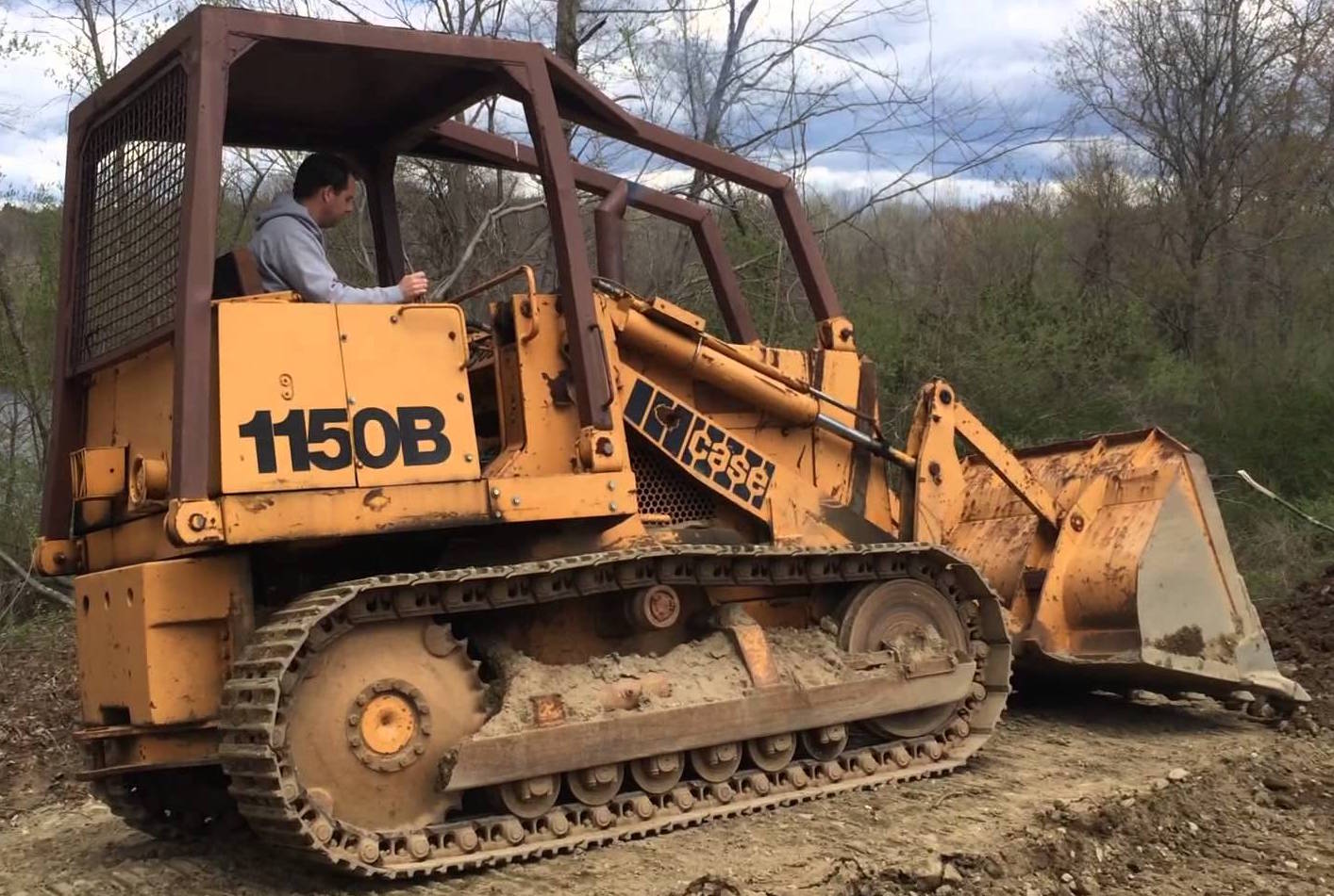
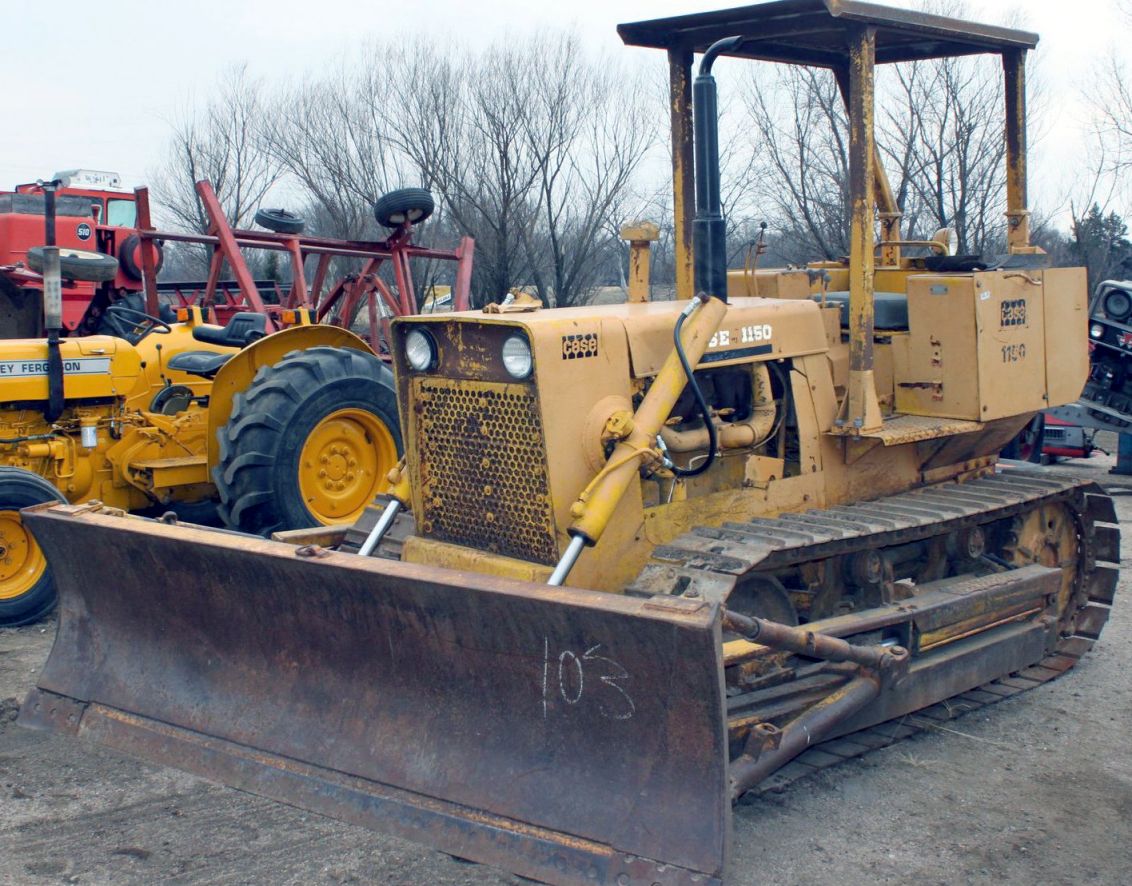
Case 1150B Crawler Workshop Repair & Service Manual
900+ total pages, bookmarked, Searchable, Printable, high quality PDF
“9-72547.pdf”
Case 1150B Crawler Service Manual
867 pages
“9-4267.pdf”
Case 1150B Crawler Operator’s Manual
122 pages
Complete digital official shop manual contains service, maintenance, and troubleshooting information for the Case 1150B Crawler. Diagnostic and repair procedures are covered in great detail to repair, maintain, rebuild, refurbish or restore your Case 1150B Crawler like a professional mechanic in local service/repair workshop. This cost-effective quality manual is 100% complete and intact as should be without any missing pages. It is the same factory shop manual used by dealers that guaranteed to be fully functional to save your precious time.
This manual for Case 1150B Crawler is divided into different sections. Each section covers a specific component or system and, in addition to the standard service procedures, includes disassembling, inspecting, and assembling instructions. A table of contents is placed at the beginning of each section. Pages are easily found by category, and each page is expandable for great detail. It is in the cross-platform PDF document format so that it works like a charm on all kinds of devices. You do not need to be skilled with a computer to use the manual.
EXCERPT:
MODEL 11508 CRAWLER
TABLE OF CONTENTS
10 SERIES- GENERAL
General Engine Specifications … 1010
Detailed Engine Specifications … 1021
Detailed Fuel Specifications .. 1030
Maintenance and Lubrication .. 1050
Torque Chart … 1051
20 SERIES- ENGINE
Engine Diagnosis … 2001
Engine Tune-Up .. 2002
Cylinder Head, Valve Train and Camshaft … 2015
Cylinder Block, Sleeves, Pistons and Rods .. 2025
Crankshaft, Main Bearing, Flywheel and Oil Seal Replacement … 2035
Lubrication System .. 2046
Stall Checks, Engine Removal and Installation .. 2050
Air Cleaner … 2051
Ether Injector Starting Aid … 2053
Cooling System … 2055
30 SERIES – FUEL SYSTEM
Fuel System and Filter … 301 0
Fuel Injection Pumps … 3012
Fuel Injectors … 3013
Fuel Tank, Lines and Throttle Adjustment … 3052
40 SERIES- HYDRAULICS
Diagrams, Troubleshooting, Maintenance, Adjustments .. 4011
Flowmeter Tests … 4011 A
Exploded Views of Hydraulic System … 4012
Diversion Valve R24819 .. 4012A
Equipment Pump R25852 … .4013
Equipment Control Valves … 4016
Loader, Ripper and Dozer Cylinders .. 4057
50 SERIES- TRACK AND SUSPENSION
Track System … 5010
Track System- Idlers (Without Lubricant Fill Plug in Hub) .. 5010A
Track System- Track Frame Removal and Installation .. 5010B
Suspension System … 5019
Guide Levers .. 5019A
Intertrac Rollers … 5505
60 SERIES- POWER TRAIN
Transmission Oil Flow- Diagrams and Operations … 6011
Troubleshooting -Transmission/Torque Converter and
Hydraulic System … 6012
Diagram, Service, Transmission Removal, Controls .. 6013
Transmission Control Valve .. 6015
Torque Converter … 6016
Charging Pump R25586 .. 6017
Drive Shafts … 6022
Crawler Transmission … 6025
Transmission, Final Drives … 6026
Transmission Brakes .. 6027
70 SERIES – BRAKES
Brakes – See Section 6027
Brake Pedals and Linkage, Parking Brake … 7010
80 SERIES- ELECTRICAL
Wiring Diagram … 8011
Troubleshooting .. 8012
Battery … 8014
Starter and Starter Solenoid .. 8015
Alternator … 8016
90. SERIES- MOUNTED EQUIPMENT
Loader … 9011
Power Tilt Dozer, Power Angle-Tilt-Pitch (ATP) Dozer … 9013
Field Removal/Installation of ATP Dozer
Blade for Transport- Supplement 1 … 9013
W5A Hyster Winch .. 9014
Ripper … 9015
ROPS .. 9019
Disassembly
1. Remove the pipe plug from the hub and drain the oil. This pipe plug is coated with Loctite Pipe Sealant and may be difficult to break loose. If required, a small amount of heat may be applied to the plug.
2. Remove the shaft lock nut from either end of the shaft. These nuts are factory torqued to 210-230 foot-pounds.
3. Remove the washer and seal retainer from the shaft. The seal retainer is held on the shaft only by the fit of an internal 0-ring, Figure 48.
4. Remove the remaining half of the face seal assembly from the !’Oller if it did not come out with the seal retainer.
5. Place the roller in a press and press the shaft and the parts still assembled to it from the roller hub. Use a sleeve or combination of sleeves of the proper length and diameter to prevent damage to the shaft or roller hub, Figure 49.
NOTE: Before pressing shaft from roller hub, place container under roller. As shaft is pressed out, any oil remaining inside reservoir of hub will run out.
6. Use a puller to remove the bearing cone and seal spacer from the side of the hub from which shaft was pressed. The seal spacer on the opposite side of the hub will be removed when the shaft is pressed from the roller, step 5.
7. Disassemble parts remaining on the shaft:
a. Clamp the shaft in a vise between brass or wood strips and remove the shaft lock nut.
b. Remove the washer and seal retainer.
c. Remove the face seal assembly from the seal retainer.
d. Press the bearing cone from the shaft.
8. Remove the Q-ring from the bore of the seal retainers.
9. A bearing cup is pressed into each side of the hub. Do not remove these cups unless they are to be replaced. To remove:
a. Fabricate the special tool shown in Figure 6.
b. Place the roller under a press. Insert the tool into the hub as shown in Figure 50 and press out the cup.
Inspection
1. Thoroughly wash all parts before inspection.
2. Clean the roller. The internal cavities of the roller must be free from the dirt, chips, rust, and all other foreign matter.
3. Make a visual inspection of the shaft and – bearings. If the bearing cones or bearing cups show excessive wear or if they are pitted, they should be replaced.
4. Disassemble the face seal assemblies.
Inspect the metal sealing rings carefully.
The area of contact between the two rings must not be in the inner half of the faces and the rings must be wearing evenly.
If the sealing rings must be replaced, replace the entire face seal assembly.
5. Discard the rubber seals even if they appear to be in good condition. A kit is available for replacement of the seals only; refer to the Case Parts Catalog.
6. Install new 0-rings in the seal retainers.
Assembly
Refer to Figures 47 and 48.
Figure 49 – Removing the Shaft
BEARING CUP
Figure 50- Bearing Cup Removal
…