Posted on

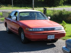
Ford Crown Victoria, Mercury Grand Marquis 1986-1998 Workshop Repair & Service Manual (COMPLETE & INFORMATIVE for DIY REPAIR) ☆ ☆ ☆ ☆ ☆

Ford Crown Victoria, Mercury Grand Marquis 1986-1998 Workshop Repair & Service Manual

Ford Crown Victoria, Mercury Grand Marquis 1986-1998 Workshop Repair & Service Manual (COMPLETE & INFORMATIVE for DIY REPAIR) ☆ ☆ ☆ ☆ ☆


MFDCVGM8698NPEK.PDF
Price: $12.99 USD

* COMPLETE, Absolutely No Missing Pages!
* Official Service INFORMATION You Can Count On!
* Customer Satisfaction GUARANTEED!

This high QUALITY official manual for Ford Crown Victoria, Mercury Grand Marquis 1986-1998 is 100 percents COMPLETE and INTACT, no MISSING, CORRUPT pages, sections to freak you out! This manual is exactly as described. It is in the cross-platform PDF document format so that it works like a charm on all kinds of devices.

FORMAT: PDF
LANGUAGE: English
OS: Windows/Mac/Linux

Ford Crown Victoria, Mercury Grand Marquis 1986 1987 1988 1989 1990 1991 1992 1993 1994 1995 1996 1997 1998

INSTANT DELIVERY: A download link will be sent to you instantly after payment. Simply click on the link and save it to your computer. You can use this Manual as long as you wish with no restrictions.

CUSTOMER SATISFACTION: If there is ANY kind of problem with the item you purchased, just drop a quick email. Within HOURS the issue shall be taken care of.

PRINTABLE MANUAL WITH DIAGRAMS: Just print the manual out and start to work. You can also use the manual with your Tablet/Laptop in your garage.

REFUND/EXCHANGE POLICY: We sell high QUALITY products only. However if you encounter any problems with the item you purchased, another replacement link will be sent to you. If we’re at fault, you will get 100 percents refund.

Buy ☆THE BEST MANUAL ON THE INTERNET☆ from responsible seller and get instant download now without uncertainty or surprise.

This highly detailed workshop service repair manual for download contains virtually everything you will ever need to repair, maintain, rebuild, refurbish or restore Your Ford Crown Victoria, Mercury Grand Marquis 1986-1998 (ALL MODELS ARE COVERED). All diagnostic and repair procedures and gives you access to the same information that professional technicians and mechanics have. You can view and print out the complete repair procedures with this workshop service repair manual Download – you do not need to be skilled with a computer.

EXCERPTS:
Engine Mechanical
Engine
REMOVAL & INSTALLATION
In the process of removing the engine, you will come across a number of steps which call for the removal of a separate component or system, such as “disconnect the exhaust system” or “remove the radiator.” In most instances, a detailed removal procedure can be found elsewhere in this manual.
It is virtually impossible to list each individual wire and hose which must be disconnected, simply because so many different model and engine combinations have been manufactured. Careful observation and common sense are the best possible approaches to any repair procedure.
Removal and installation of the engine can be made easier if you follow these basic points:
If you have to drain any of the fluids, use a suitable container.
Always tag any wires or hoses and, if possible, the components they came from before disconnecting them.
Because there are so many bolts and fasteners involved, store and label the retainers from components separately in muffin pans, jars or coffee cans. This will prevent confusion during installation.
After unbolting the transmission or transaxle, always make sure it is properly supported.
If it is necessary to disconnect the air conditioning system, have this service performed by a qualified technician using a recovery/recycling station. If the system does not have to be disconnected, unbolt the compressor and set it aside.
When unbolting the engine mounts, always make sure the engine is properly supported. When removing the engine, make sure that any lifting devices are properly attached to the engine. It is recommended that if your engine is supplied with lifting hooks, your lifting apparatus be attached to them.
Lift the engine from its compartment slowly, checking that no hoses, wires or other components are still connected.
After the engine is clear of the compartment, place it on an engine stand or workbench.
After the engine has been removed, you can perform a partial or full teardown of the engine using the procedures outlined in this manual.
4.6L Engine
If your vehicle is equipped with air conditioning, refer to Section 1 for information regarding the implications of servicing your A/C system yourself. Only a MVAC-trained, EPA-certified, automotive technician should service the A/C system or its components.
1. Have the A/C system recovered by a MVAC-trained, EPA-certified, automotive technician.
2. Disconnect the negative, then the positive battery cable.
3. Drain the engine oil and the cooling system into suitable containers.

MFDCVGM8698NPEK.PDF
Price: $12.99 USD

Posted on

Ford 1998 Cars & Trucks Workshop Repair & Service Manual (COMPLETE & INFORMATIVE for DIY REPAIR) ☆ ☆ ☆ ☆ ☆

Ford 1998 Cars & Trucks Workshop Repair & Service Manual (COMPLETE & INFORMATIVE for DIY REPAIR) ☆ ☆ ☆ ☆ ☆

Ford 1998 Cars & Trucks Workshop Repair & Service Manual (COMPLETE & INFORMATIVE for DIY REPAIR) ☆ ☆ ☆ ☆ ☆


MFDALL98OMES
Price: $19.99 USD

* COMPLETE, Absolutely No Missing Pages!
* Official Service INFORMATION You Can Count On!
* Customer Satisfaction GUARANTEED!

This high QUALITY official manual for Ford 1998 Cars & Trucks is 100 percents COMPLETE and INTACT, no MISSING, CORRUPT pages, sections to freak you out! This manual is exactly as described. It is in the cross-platform PDF document format so that it works like a charm on all kinds of devices.

MAKE: Ford
YEAR: 1998
MODEL:
AeroMax, Continental, Contour/Mystique, Crown Victoria, Econoline, Escort, Expedition, Explorer, F-& B-Series, F-150/250, Grand Marquis, Louisville, Mark VIII, Mountaineer, Mustang, Navigator, Ranger, Sable, Taurus, Town Car, Tracer, Villager, Windstar

FORMAT: ISO
LANGUAGE: English
SIZE/PAGE: 382 MB + 282 MB
OS: Windows (Mac OS X using Virtual Machine)

INSTANT DELIVERY: A download link will be sent to you instantly after payment. Simply click on the link and save it to your computer. You can use this Manual as long as you wish with no restrictions.

CUSTOMER SATISFACTION: If there is ANY kind of problem with the item you purchased, just drop a quick email. Within HOURS the issue shall be taken care of.

PRINTABLE MANUAL WITH DIAGRAMS: Just print the manual out and start to work. You can also use the manual with your Tablet/Laptop in your garage.

REFUND/EXCHANGE POLICY: We sell high QUALITY products only. However if you encounter any problems with the item you purchased, another replacement link will be sent to you. If we’re at fault, you will get 100 percents refund.

Buy ☆THE BEST MANUAL ON THE INTERNET☆ from responsible seller and get instant download now without uncertainty or surprise.

This highly detailed workshop service repair manual for download contains virtually everything you will ever need to repair, maintain, rebuild, refurbish or restore Ford 1998 Cars & Trucks. All diagnostic and repair procedures and gives you access to the same information that professional technicians and mechanics have. You can view and print out the complete repair procedures with this workshop service repair manual Download – you do not need to be skilled with a computer.

EXCERPTS:
Transmission Fluid Cooler and Tubes
When internal wear or damage has occurred in the transmission, metal particles, clutch plate material or band material may have been carried into the torque converter (7902) and OTA fluid cooler. These contaminants are a major cause of recurring transmission troubles and must be removed from the system before the transmission is put back into service. Replace the OTA fluid cooler.
The OTA cooler must be replaced under the following conditions:
Evidence of transmission assembly or fluid contamination is found due to the following transmission or converter failure modes:
l major metallic failure.
l multiple clutches or clutch plate failures.
l sufficient component wear which results in metallic contamination.
Inspect cooler tubes and fittings for damage and leaks. Tighten fittings to specification. If leak persists, replace fittings and tubes as necessary.
After the fittings have been tightened to specification, add MERCON® V Automatic Transmission Fluid XT-5-QM or equivalent meeting Ford MERCON® V specification as necessary and check for fluid leaks.
Three Way Catalytic Converter (TWC)
Removal
WARNING:
THE NORMAL OPERATING TEMPERATURE OF THE EXHAUST SYSTEM IS VERY HIGH. NEVER WORK AROUND OR ATTEMPT TO SERVICE ANY PART OF THE EXHAUST SYSTEM UNTIL IT HAS COOLED. USE SPECIAL CARE WHEN WORKING AROUND THE THREE WAY CATALYTIC CONVERTER (TWC) (5E212). THESE UNITS HEAT TO A HIGH TEMPERATURE AFTER ONLY A SHORT PERIOD OF ENGINE OPERATION.
1. Raise vehicle. Refer to «Section 00-02».
2. Disconnect heated oxygen sensor electrical connectors.
3. Remove the retaining bolts at each three-way catalytic converter flange.
4. Remove the three-way catalytic converter to exhaust manifold retaining nuts.
5. Slide the exhaust inlet pipe (5246) rearward until the three way catalytic converters can be removed. It may be necessary to obtain sufficient clearance to separate the three way catalytic converter at exhaust manifold connection(s).
6. Discard exhaust converter outlet gaskets (5E241) and any damaged parts.


MFDALL98OMES
Price: $19.99 USD

Posted on

Ford Models 1997 Workshop Repair & Service Manual ☆COMPLETE & INFORMATIVE for DIY REPAIR☆

Ford Models 1997 Workshop Repair & Service Manual ☆COMPLETE & INFORMATIVE for DIY REPAIR☆

MFDALL97OMEK
Price: $19.99 USD

Ford Models 1997 Workshop Repair & Service Manual ☆COMPLETE & INFORMATIVE for DIY REPAIR☆

* COMPLETE, Absolutely No Missing Pages!
* Official Service INFORMATION You Can Count On!
* Customer Satisfaction GUARANTEED!

This high QUALITY official manual for Ford Models 1997 is 100 percents COMPLETE and INTACT, no MISSING, CORRUPT pages, sections to freak you out! This manual is exactly as described.

MAKE: Ford
YEAR: 1997
MODEL:
Aspire, Continental, Contour, Cougar, Crown Victoria, Escort, Grand Marquis, Mark VIII, Mustang, Mystique, Probe, Sable, Taurus, Thunderbird, Town Car, Tracer
AeroMax, AeroStar, Cargo, Econoline, Expedition, Explorer, F-&B-Series, F-150/250, F-250/350, Super Duty, Louisville, L-Series, Mountaineer, Ranger, Villager, Windstar
INSTANT DELIVERY: A download link will be sent to you instantly after payment. Simply click on the link and save it to your computer. You can use this Manual as long as you wish with no restrictions.

CUSTOMER SATISFACTION: If there is ANY kind of problem with the item you purchased, just drop a quick email. Within HOURS the issue shall be taken care of.

PRINTABLE MANUAL WITH DIAGRAMS: Just print the manual out and start to work. You can also use the manual with your Tablet/Laptop in your garage.

REFUND/EXCHANGE POLICY: We sell high QUALITY products only. However if you encounter any problems with the item you purchased, another replacement link will be sent to you. If we’re at fault, you will get 100 percents refund.

Buy ☆THE BEST MANUAL ON THE INTERNET☆ from responsible seller and get instant download now without uncertainty or surprise.

This highly detailed workshop service repair manual for download contains virtually everything you will ever need to repair, maintain, rebuild, refurbish or restore Your Ford Models 1997 (ALL MODELS ARE COVERED). All diagnostic and repair procedures and gives you access to the same information that professional technicians and mechanics have. You can view and print out the complete repair procedures with this workshop service repair manual Download – you do not need to be skilled with a computer.

EXCERPTS:
Door Window Moulding–Front and Rear
Removal and Installation
1. Remove nine screws and washers and remove rear door window moulding.
2. Gently pry front door window filler rear edge from retainers.
3. Remove nine screws and washers and remove front door window moulding.
4. To install, reverse Removal procedure.
Door Window Moulding
Luggage Compartment Door
Refer to the following illustration for Removal and Installation of luggage compartment door moulding (42509).
Luggage Compartment Door
Preheat Procedure
Note:
Be sure that any body wax is removed before using the infrared lamps.
The recommended preheat treatment requires the use of an infrared lamp bank. The bank should be positioned approximately 750 mm (30 inches) from the desired location of the body.
Suspension
There are three major components in the rear suspension system:
l Rear suspension lower arms (5A649)
l Rear springs (5560)
l Rear shock absorbers (18080)
The rear axle housing is suspended from the vehicle frame as follows:
l Two short rear suspension arm and bushings (5500) control the side-to-side sway of the vehicle.
l Two longer rear suspension lower arms manage the forward and rearward movement of the rear axle housing.
Exhaust System
WARNING:
THE NORMAL OPERATING TEMPERATURE OF THE EXHAUST SYSTEM IS VERY HIGH. NEVER ATTEMPT TO SERVICE ANY PART OF THE SYSTEM UNTIL IT HAS COOLED. BE ESPECIALLY CAREFUL WHEN WORKING AROUND THE THREE WAY CATALYTIC CONVERTER (TWC) (5E212). THE TEMPERATURE OF THE THREE WAY CATALYTIC CONVERTER RISES TO A HIGH LEVEL AFTER ONLY A FEW MINUTES OF ENGINE OPERATION.
CAUTION:
When servicing exhaust system or removing exhaust components, disconnect all heated oxygen sensors (HO2S) (9F472) at the wiring connectors to prevent damage to the heated oxygen sensors and wiring harness. Refer to «Section 03-14» for location of the heated oxygen sensors.
This section covers the general exhaust system adjustments and service procedures.
The factory-installed exhaust systems shown in the illustrations in «Removal and Installation» differ from the service replacement systems in the number of pieces used. When making a service replacement, refer to the Master Parts Catalog for the current assemblies.
Always refer to the Master Parts Catalog for parts usage and interchangeability before replacing a component part of the exhaust system.
The exhaust systems are equipped with the following:
l two three way catalytic converters.
l twomufflers (5230).
l interconnecting exhaust inlet pipes (5246).
The exhaust system must be free of the following:
l leaks
l binding
l grounding
l excessive vibrations
These conditions are usually caused by loose, broken or misaligned:
l clamps.
l shields.
l brackets.
l pipes.
If any of these conditions exist, check the exhaust system components and alignment. Adjust or replace as necessary to maintain the specified clearances (refer to the illustrations). Replace these parts if they are damaged or badly corroded. Do not attempt to service brackets, clamps or insulators.
Refer to the appropriate system illustration when servicing the exhaust system.
Three Way Catalytic Converter (TWC)
The three way catalytic converter:
l is mounted in the engine exhaust stream.
l plays a major role in the emission control system.
l works as a gas reactor.
l provides catalytic function which speeds up the heat producing chemical reaction between components of the exhaust gases in order to reduce the air pollutants.
l houses catalytic material that is made of a ceramic substrate which is coated with a high surface area alumina and impregnated with catalytically active platinum.
l provides access to the surface of the catalyst material that plays a major role in the heat producing chemical reaction.
Precautions
WARNING:
EXHAUST GASES CONTAIN CARBON MONOXIDE WHICH CAN BE HARMFUL TO HEALTH AND ARE POTENTIALLY LETHAL. EXHAUST SYSTEM LEAKS SHOULD BE SERVICED IMMEDIATELY. NEVER OPERATE THE ENGINE IN ENCLOSED AREAS.
CAUTION:
Leaded fuel must not be used in a vehicle fitted with a three way catalytic converter–the lead will damage the catalyst.
The following precautions must be observed when operating a vehicle equipped withthree way catalytic converters.
If a vehicle is continually misfueled:
l the lead in the fuel will be deposited in the converter and completely blanket the catalyst.
l lead combines chemically with platinum to damage the catalyst.
l continuous use of leaded fuels can totally destroy the catalyst and render the converter useless.
The addition of lead to the converter can also solidify the catalyst, causing:
l excessive back pressure in the exhaust system.
l possible engine damage.
Extremely high temperatures of 1100°C (2012°F) or over, due to misfiring or over-rich fuel/air mixture, will cause the ceramic base to sinter or burn, destroying the converter.
The three way catalytic converters have been designed to provide a long service life. No maintenance is necessary for the three way catalytic converters. However, the following conditions must be avoided:
l Do not drive downhill with the gears engaged and the ignition switch OFF.
l Do not drive with misfiring engine.
l Do not run the engine continuously with a misfiring spark plug (12405). When idling is unstable or when the engine lacks power, refer to the «Powertrain Control/Emissions Diagnosis Manual».
l Do not park or stop the vehicle over combustible material. If the vehicle is parked or stopped over combustible material such as dry grass, the material may be ignited by the high temperature of the three way catalytic converter and muffler.


MFDALL97OMEK
Price: $19.99 USD

Posted on

Ford Models 1995 Workshop Repair & Service Manual ☆COMPLETE & INFORMATIVE for DIY REPAIR☆

Ford 1995
Ford 1995

Ford Models 1995 Workshop Repair & Service Manual ☆COMPLETE & INFORMATIVE for DIY REPAIR☆


MFDALL95OMES
Price: $19.99 USD

* COMPLETE, Absolutely No Missing Pages!
* Official Service INFORMATION You Can Count On!
* Customer Satisfaction GUARANTEED!

This high QUALITY official manual for Ford 1995 Models is 100 percents COMPLETE and INTACT, no MISSING, CORRUPT pages, sections to freak you out! This manual is exactly as described.

1995 Ford Aerostar
1995 Ford Bronco
1995 Ford Cargo
1995 Ford Econoline
1995 Ford Explorer
1995 Ford F-& B-Series
1995 Ford F-Series
1995 Ford F-Super Duty
1995 Ford L-Series
1995 Ford Pre-Delivery
1995 Ford Villager
1995 Ford Windstar

INSTANT DELIVERY: A download link will be sent to you instantly after payment. Simply click on the link and save it to your computer. You can use this Manual as long as you wish with no restrictions.

CUSTOMER SATISFACTION: If there is ANY kind of problem with the item you purchased, just drop a quick email. Within HOURS the issue shall be taken care of.

PRINTABLE MANUAL WITH DIAGRAMS: Just print the manual out and start to work. You can also use the manual with your Tablet/Laptop in your garage.

REFUND/EXCHANGE POLICY: We sell high QUALITY products only. However if you encounter any problems with the item you purchased, another replacement link will be sent to you. If we’re at fault, you will get 100 percents refund.

Buy ☆THE BEST MANUAL ON THE INTERNET☆ from responsible seller and get instant download now without uncertainty or surprise.

This highly detailed workshop service repair manual for download contains virtually everything you will ever need to repair, maintain, rebuild, refurbish or restore Your Ford Models 1995 (ALL MODELS ARE COVERED). All diagnostic and repair procedures and gives you access to the same information that professional technicians and mechanics have. You can view and print out the complete repair procedures with this workshop service repair manual Download – you do not need to be skilled with a computer.

EXCERPTS:
Group 07: TRANSMISSION
² SECTION 07-01A: Transmission, Automatic, E4OD
² SECTION 07-01B: Transmission, Automatic, C6
² SECTION 07-01C: Transmission, Automatic, 4R70W
² SECTION 07-02: Transmission, Automatic, Cooling
² SECTION 07-05: Transmission, Automatic, External Controls
² SECTION 07-14A: Transmission Range (TR) Sensor
² SECTION 07-14B: Park/Neutral Position (PNP) Switch
SECTION 07-01C: Transmission, Automatic, 4R70W
VEHICLE APPLICATION
E-150 Equipped with 5.0L Engines
² DESCRIPTION AND OPERATION
² DIAGNOSIS AND TESTING
² IN-VEHICLE SERVICE
² REMOVAL
² DISASSEMBLY
² DISASSEMBLY AND ASSEMBLY OF SUBASSEMBLIES
Transmission Fluid Drain and Fill Procedure
Normal maintenance and lubrication requirements do not necessitate periodic automatic transmission fluid changes. If a major service, such as a clutch, band, bearing, etc., is required, it will have to be removed for service. At this time, the torque converter (7902), transmission fluid cooler (7A095) and oil cooler inlet tube (7A030) and oil cooler tube (7A031) must be thoroughly flushed to remove any dirt. When used under continuous or severe conditions, the transmission and torque converter should be drained and refilled with fluid as specified.
CAUTION:
Use of a fluid other than specified could result in transmission malfunction and/or failure.
Refer to the Vehicle Certification Label affixed to the LH front door lock face panel or door pillar for the transmission code.
When filling a dry transmission and torque converter, refer to «Specifications» for capacity. Check the fluid level.
Procedures for partial drain and refill, due to in-vehicle service operation, are as follows:
1. Raise vehicle on a hoist or jackstands. Refer to «Section 00-02».
2. Place drain pan under transmission.
3. Loosen oil pan retaining bolts and drain fluid from transmission.
4. When fluid has drained to level of pan flange, remove rest of pan bolts working from the RH side, and allow it to drop and drain slowly.
5. When all fluid has drained from transmission, remove and thoroughly clean transmission oil pan (7A194).
6. Place a oil pan to case gasket (7A191) on transmission oil pan, and install transmission oil pan on transmission.
7. Lower vehicle.
8. Fill transmission to proper level with Motorcraft MERCON® Multi-Purpose Automatic Transmission Fluid E6AZ-19582 or MERCON® equivalent meeting Ford specification ESR-M2C163-AZ.


MFDALL95OMES
Price: $19.99 USD

Posted on

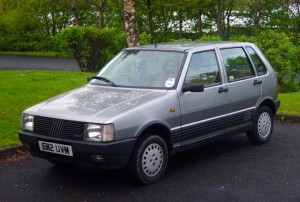
Fiat Uno 1983-1995 Workshop Repair & Service Manual (COMPLETE & INFORMATIVE for DIY REPAIR) ☆ ☆ ☆ ☆ ☆

Fiat Uno 1983-1995 Workshop Repair & Service Manual (COMPLETE & INFORMATIVE for DIY REPAIR)

Fiat Uno 1983-1995 Workshop Repair & Service Manual (COMPLETE & INFORMATIVE for DIY REPAIR) ☆ ☆ ☆ ☆ ☆


MFIATUNO8395NPEK.PDF
Price: $9.99 USD

* COMPLETE, Absolutely No Missing Pages!
* Official Service INFORMATION You Can Count On!
* Customer Satisfaction GUARANTEED!

This high QUALITY official manual for Fiat Uno 1983-1995 is 100 percents COMPLETE and INTACT, no MISSING, CORRUPT pages, sections to freak you out! This manual is exactly as described. It is in the cross-platform PDF document format so that it works like a charm on all kinds of devices.

FORMAT: PDF
LANGUAGE: English
SIZE/PAGE: 304 Pages
OS: Windows/Mac OS X/Linux/Android/iOS

INSTANT DELIVERY: A download link will be sent to you instantly after payment. Simply click on the link and save it to your computer. You can use this Manual as long as you wish with no restrictions.

CUSTOMER SATISFACTION: If there is ANY kind of problem with the item you purchased, just drop a quick email. Within HOURS the issue shall be taken care of.

PRINTABLE MANUAL WITH DIAGRAMS: Just print the manual out and start to work. You can also use the manual with your Tablet/Laptop in your garage.

REFUND/EXCHANGE POLICY: We sell high QUALITY products only. However if you encounter any problems with the item you purchased, another replacement link will be sent to you. If we’re at fault, you will get 100 percents refund.

Buy ☆THE BEST MANUAL ON THE INTERNET☆ from responsible seller and get instant download now without uncertainty or surprise.

This highly detailed workshop service repair manual for download contains virtually everything you will ever need to repair, maintain, rebuild, refurbish or restore Fiat Uno 1983-1995. All diagnostic and repair procedures and gives you access to the same information that professional technicians and mechanics have. You can view and print out the complete repair procedures with this workshop service repair manual Download – you do not need to be skilled with a computer.

EXCERPTS:
Flywheel
26 Check the clutch mating surface of the flywheel. If it is deeply scored (due to failure to
renew a worn driven plate) then it may be possible to have it surface ground provided
the thickness of the flywheel is not reduced too much.
27 If lots of tiny cracks are visible on the surface of the flywheel then this will be due to
overheating caused by slipping the clutch or “riding” the clutch pedal.
28 With a pre-engaged type of starter motor it is rare to find the teeth of the flywheel ring
gear damaged or worn but if they are, then the ring gear will have to be renewed.
29 To remove the ring gear, drill a hole between the roots of two teeth taking care not
to damage the flywheel and then split the ring with a sharp cold chisel.
30 The new ring gear must be heated to between 180 and 220ºC (356 and 428ºF) which is very hot, so if you do not have facilities for obtaining these temperatures, leave the job to your dealer or engine re-conditioner.
31 Where such facilities are available, then the ring gear should be either pressed or lightly tapped gently onto its register and left to cool naturally, when the contraction of the metal on cooling will ensure that it is a secure and permanent fit. Great care must be taken not to overheat the ring gear, as if this happens its temper will be lost. A clutch input shaft pilot bearing is not fitted on this engine.
Camshaft
32 Examine the camshaft bearings for wear, scoring or pitting. If evident then the bearings will have to be renewed. The three bearings are of different sizes and they can be removed and new ones fitted using a bolt, nut and distance pieces. When drawing a new bearing into position, make sure that the oil hole is correctly aligned with the one in the crankcase. The centre and rear bearings require reaming after fitting, the bearing at the timing chain end is supplied ready reamed
(photo).
33 The camshaft itself should show no marks or scoring on the journal or cam lobe surfaces. Where evident, renew the camshaft or have it reprofiled by a specialist reconditioner.
34 Check the teeth of the camshaft sprocket for wear. Renew the sprocket if necessary.
Cam followers
35 Examine the bearing surface of the cam followers which are in contact with the camshaft. Any indentations or cracks must be rectified by renewal. Clean sludge and dirt from the cam followers and check their fit in their bores. Side to side rock is unusual except at very high mileage.
Timing chain
36 Examine the teeth on both the crankshaft sprocket and the camshaft sprocket for wear.
Each tooth forms an inverted “V” with the sprocket periphery and if worn, the side of each tooth under tension will be slightly concave in shape when compared with the other side of the tooth, ie; one side of the inverted “V” will be concave when compared with the other. If any sign of wear is present the sprockets must be renewed.
37 Examine the links of the chain for side slackness and particularly check the self-tensioning links for freedom of movement. Renew the chain if any slackness is noticeable when compared with a new chain. It is a sensible precaution to renew the chain at about 60,000 miles (96,000 km) and at a lesser mileage if the engine is stripped down for a major overhaul.
Cylinder head
38 This is covered in Section 17. Rockers and rocker shaft
39 Thoroughly clean out the rocker shaft. As it acts as the oil passages for the valve gear, clean out the oil holes and make sure they are quite clear. Check the shaft for straightness by rolling it on a flat surface. If it is distorted, renew it.
40 The surface of the shaft should be free from any wear ridges caused by the rocker arms. If it is not, the shaft will have to be renewed. Blocked shaft oil holes often contribute to such wear.
41 Check the rocker arms for wear of the rocker bushes, for wear at the rocker arm face which bears on the valve stem, and for wear of the adjusting ball ended screws. Wear in the rocker arm bush can be checked by gripping the rocker arm tip and holding the rocker arm in place on the shaft, noting if there is any lateral rocker arm shake. If any shake is present, and the arm is very loose on the shaft, remedial action must be taken. It is recommended that a worn rocker arm be taken to your local FIAT agent or automobile engineering works to have the old bush drawn out and a new bush fitted (photo).
42 Check the tip of the rocker arm where it bears on the valve head, for cracking or serious wear on the case hardening. If none is present the rocker arm may be refitted. Check the pushrods for straightness by rolling them on a flat surface.


MFIATUNO8395NPEK.PDF
Price: $9.99 USD