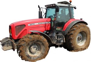
Complete workshop & service manual with electrical wiring diagrams for AGCO / Massey Ferguson 8200 Series Tractors (8210, 8220, 8220 Heavy Duty, 8220 Xtra, 8240, 8240 Xtra, 8245, 8245 Heavy Duty, 8250, 8250 Xtra, 8260, 8260 Xtra, 8270, 8270 Xtra, 8280, 8280 Xtra). It’s the same service manual used by dealers that guaranteed to be fully functional and intact without any missing page.
This AGCO / Massey Ferguson 8200 Series Tractors service & repair manual (including maintenance, overhaul, disassembling & assembling, adjustment, tune-up, operation, inspecting, diagnostic & troubleshooting…) is divided into different sections. Each section covers a specific component or system with detailed illustrations. A table of contents is placed at the beginning of each section. Pages are easily found by category, and each page is expandable for great detail. The printer-ready PDF documents work like a charm on all kinds of devices.
Workshop Service Manual for AGCO / Massey Ferguson 8200 Series Tractors (8210, 8220, 8220 Heavy Duty, 8220 Xtra, 8240, 8240 Xtra, 8245, 8245 Heavy Duty, 8250, 8250 Xtra, 8260, 8260 Xtra, 8270, 8270 Xtra, 8280, 8280 Xtra) (Three Point Power, Wintest User Guide)
N° 3378177 M1; May 2001; 2,335 pages
EXCERPT:
8 . FRONT AXLE
8 A01 GENERALITY – CARRARO FRONT AXLE
8 B01 DANA FINAL DRIVE UNITS
8 B02 ZF FINAL DRIVE UNITS
8 B03 CARRARO FINAL DRIVE UNITS
8 C01 DANA DIFFERENTIAL
8 C02 ZF DIFFERENTIAL
8 C03 CARRARO DIFFERENTIAL
8 D01 2 WD FRONT AXLE
8 E01 STEERING COLUMN
8 F01 BEARINGS AND TRANSMISSION SHAFTS (DANA FRONT AXLE)
8 F02 BEARINGS AND TRANSMISSION SHAFTS (ZF FRONT AXLE)
8 F03 BEARINGS AND TRANSMISSION SHAFTS (CARRARO FRONT AXLE)
8 G01 4WD CLUTCH
8 G02 CARRARO SUSPENSION
8 I01 CARRARO TROUBLESHOOTING
…
Front axle – Generality
The axle described in this manual, designed and manufactured following the customer’s requests, consists of a beam casing, housing the differential in the middle and a wheel hub unit at each end.
The differential, type “Limited Slip”, is supported by two bearings mounted on a suitable structure allowing the bevel gear set to be adjusted.
The ring bevel gear is adjusted by means of two ring nuts located opposite each other.
The position of the bevel pinion, supported by two bearings, is adjusted by inserting adjusting shims.
The wheel hubs containing the epicyclic reduction gears are supported by two tapered roller bearings and are powered by a hydraulically-operated steering unit.
The axle is equipped with hydropneumatic shock-absorbing suspension system (Carraro patent), electronically controlled, ensuring the constant contact of the tyres with the ground in any operating conditions.
…
