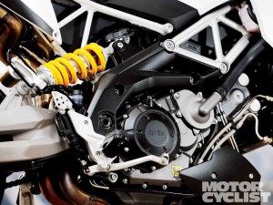
Aprilia V990 Engine Workshop Repair & Service Manual (Printable, iPad-ready PDF)
Complete digital workshop service and repair manual written for your Aprilia V990 Engine. All styles covered (all models, and engines). It is in the cross-platform PDF document format so that it works like a charm on all kinds of devices.
This QUALITY manual is 100% COMPLETE and INTACT, no MISSING/CORRUPT pages/sections to freak you out! Buy from responsible seller and get INSTANT DOWNLOAD now without wasting your hard-owned money on uncertainty or surprise; this manual for Aprilia V990 Engine is exactly as described.
PRODUCT DETAILS:
Total Pages: 186 pages
File Format: PDF (Windows & Mac & Linux)
Language: English
Delivery: instant download link displayed on checkout page & emailed to you after payment
Protection: DRM-free; without any restriction
Printable: Yes
This COMPLETE full workshop service repair manual for Aprilia V990 Engine includes:
* Detailed sub-steps expand on repair procedure information
* Notes, cautions and warnings throughout each chapter pinpoint critical information.
* Numbered instructions guide you through every repair procedure step by step.
* Bold figure number help you quickly match illustrations with instructions.
* Detailed illustrations, drawings and photos guide you through every procedure.
* Enlarged inset helps you identify and examine parts in detail.
* Numbered table of contents easy to use so that you can find the information you need fast.
* This manual also makes it easy to diagnose and repair problems with your machines electrical system.
* Troubleshooting and electrical service procedures are combined with detailed wiring diagrams for ease of use.
* COMPLETE, Absolutely No Missing Pages!
* Customer Satisfaction GUARANTEED!
EXCERPT (Aprilia V990 Engine Service/Repair Manual):
INTRODUCTION
GENERAL INFORMATION
TECHNICAL INFORMATION
REMOVING/REFITTING THE COMPLETE ENGINE
FROM/TO THE VEHICLE FRAME
DISASSEMBLING THE ENGINE
WORK ON THE ENGINE INDIVIDUAL PARTS
REASSEMBLING THE ENGINE
FUEL SYSTEM, COOLING SYSTEM, ELECTRICAL SYSTEM
TROUBLESHOOTING
ANALYTICAL INDEX
4.8 REMOVING THE ALTERNATOR COVER AND ALTERNATOR SYSTEM
Carefully read 4.2 (IMPORTANT INFORMATION).
NOTE The following operations can be performed with out removing the engine from the frame.
A WARNING
When performing work on the ignition system:
– switch off the engine;
– disconnect the battery: always disconnect the negative pole (-) first;
– disconnect all the electrical connections;
– drain the engine oil tank completely, consult the section 2 (SERVICE AND SETTING UP) of specific vehicle workshop manual see 0.4.1 (VEHICLE WORKSHOP MANUAL);
– lock the crankshaft at the TDC of piston “1” or “2”.
♦ ESI ESZ3 E l Disconnect the connector (A) of the sta- tor (A1).
♦ EH1 H il Disconnect the connector (B) of stator (B1).
♦ Em Bali Disconnect the connector (C) from the crank
shaft position sensor (Cl).
♦ Remove the plastic plug (D) and O-ring (E) located in
the center of the alternator cover (3).
♦ Unscrew and remove the twelve Allen screws M6 (1).
Do not mix up parts from cylinder “1” and cylinder “2” cam drive assemblies. Upon reassembly, ensure that you put all parts in their original positions.
♦ Check the flanks of the teeth on the timing gear (1), drive gears (2) and intermediate drive gears (3) for pit ting and wear.
♦ Check the bore (4) of the idler gears (3) for wear.
Bore (4) wear limit: max. diameter 0.788 in (20.015 mm).
♦ Check the roller bearings (5) for wear.
♦ Check the two bearing flanges (6) for wear around the
bearing support surface (7) of the roller bearings (5).
Bearing support surface (7) wear limit: min. diameter 0.629 in (15.98 mm).
♦ Check the chain guide shoe (8), chain tensioner shoe (9), chain guide (10) and chain guide bracket (11) for any traces of galling or scoring.
Max. depth of the galling or scoring traces: 0.047 in (1.2 mm).
♦ Check the teeth of the two timing chains (12) for any signs of distortion.
♦ Stretch the cam chain tight, count 20 pins (19 links), and measure the distance (13) between the centers of the first and the twentieth pin. Repeat for the second cam chain.
Distance (13) wear limit: max. 6.54 in (166.2 mm).