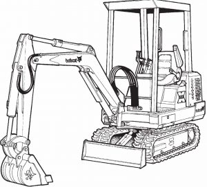
Pages from Service Manual (X220 Excavator) 6720503 (6-90)
Complete workshop & service manual with electrical wiring diagrams for Bobcat 220, X220 Excavator. It’s the same service manual used by dealers that guaranteed to be fully functional and intact without any missing page.
This Bobcat 220, X220 Excavator service & repair manual (including maintenance, overhaul, disassembling & assembling, adjustment, tune-up, operation, inspecting, diagnostic & troubleshooting…) is divided into different sections. Each section covers a specific component or system with detailed illustrations. A table of contents is placed at the beginning of each section. Pages are easily found by category, and each page is expandable for great detail. The printer-ready PDF documents work like a charm on all kinds of devices.
FILELIST:
Operation & Maintenance Manual (220 Excavator) 6720124 (11-89).pdf
Operation & Maintenance Manual (220 Excavator) 6720379 (11-89).pdf
Operation & Maintenance Manual (220 Excavator) 6720448 (4-92).pdf
Operation & Maintenance Manual (X220 Excavator) 6722250 (10-98).pdf
Service Manual (220 Excavator) 6722345 (9-92).pdf
Service Manual (X220 Excavator) 6720230 (5-89).pdf
Service Manual (X220 Excavator) 6720503 (6-90).pdf
EXCERPT:
“SWING MOTOR (Cont’d)”
“Assembly (Cont’d)”
“Clamp the shaft and bearing housing so the output shaft is down.”
“Pour a small amount of clean hydraulic fluid into the shaft and bearing housing for start–up lubrication.”
“Install the shaft face seal and wear plate as shown [A]. Install the drive, Geroler and valve drive.”
“Motor Timing”
“The direction that the output shaft rotates is determined by timing. Time the motor as follows:”
“Locate the largest open pocket in the Geroler (Item 1) [B]. Install the valve plate (Item 2) [B] and locate the open slot that is over the largest open Geroler pocket.”
“Align one of the side openings in the valve with the valve plate slot that is over the largest open Geroler pocket.”
“Engage the valve with the valve drive (Item 3) [B] by rotating it clockwise until the spline teeth mesh (1/2 tooth).”
“Install the inner and outer face seals on the balance ring as shown [C].”
“Install the springs, pins and balance ring in the valve housing. Hold the balance ring in place, through the forward port in the valve housing, while installing the valve housing over the valve.”
“Install and tighten the four bolts in a crisscross pattern. Tighten the bolts to 450 in.–lbs. (50 Nm) torque. Tighten the case drain plug to 50 in.–lbs. (5,5 Nm) torque.”
…
