INSTANT DOWNLOAD (add to cart)
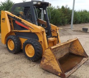
Complete workshop & service manual with electrical wiring diagrams for Case 410, 420 Skid Steers. It’s the same service manual used by dealers that guaranteed to be fully functional and intact without any missing page.
Case 410, 420 Skid Steers service & repair manual (including maintenance, overhaul, disassembling & assembling, adjustment, tune-up, operation, inspecting, diagnostic & troubleshooting…) is divided into different sections. Each section covers a specific component or system with detailed illustrations. A table of contents is placed at the beginning of each section. Pages are easily found by category, and each page is expandable for great detail. The printer-ready PDF documents work like a charm on all kinds of devices.
468 pages, bookmarked, Searchable, Printable, high quality PDF
6-78950 – Case 410, 420 SKID STEER Service Manual
EXCERPT:
STARTER SOLENOID TEST
This test will check the condition of the pull-in winding and the hold-in winding in the starter solenoid.
The jumper cable connected to the starter mounting flange and the motor terminal must have a common connection at the negative battery post.
Starter Solenoid Test Procedure
1. Remove the rubber boot from the motor terminal. Remove the nut and lock washer from the motor terminal. Then remove the wire from the motor terminal.
2. Connect a jumper cable to the positive battery post of a fully charged 12 volt battery. Connect the other end of the jumper cable to the battery terminal in the starter solenoid housing.
3. Connect a jumper wire to the battery terminal and the switch terminal in the starter solenoid housing. The jumper wire must be made from No. 10 or larger wire.
4. Connect the jumper cable with the common connection to the starter mounting flange and the motor terminal in the starter solenoid housing.
NOTE: Steps 5 and 7 must be done in a maximum of 15 seconds to prevent damage to the pull-in winding and the hold-in winding.
5. Connect the jumper cable with the common connection to the negative battery post. The pinion gear on the starter drive must come all the way out rapidly and with force.
6. If the pinion gear did not come out rapidly and with force, the pull-in winding is damaged. The complete starter solenoid housing assembly must be replaced.
7. Disconnect the jumper cable from the motor terminal in the starter solenoid housing. The pinion gear on the starter drive must not move toward the starter drive housing.
8. If the pinion gear started to move toward the starter drive housing, the hold-in winding is damaged. The complete starter solenoid housing assembly must be replaced.
…

