INSTANT DOWNLOAD (add to cart)
865 total pages, bookmarked, Searchable, Printable, high quality PDF
6-46503 – 845, 865, 885 Grader Service Manual.pdf
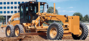
Complete digital official shop manual contains service, maintenance, and troubleshooting information for the Case 845, 865, 885 Grader. Diagnostic and repair procedures are covered in great detail to repair, maintain, rebuild, refurbish or restore your Case 845, 865, 885 Grader like a professional mechanic in local service/repair workshop. This cost-effective quality manual is 100% complete and intact as should be without any missing pages. It is the same factory shop manual used by dealers that guaranteed to be fully functional to save your precious time.
This manual for Case 845, 865, 885 Grader is divided into different sections. Each section covers a specific component or system and, in addition to the standard service procedures, includes disassembling, inspecting, and assembling instructions. A table of contents is placed at the beginning of each section. Pages are easily found by category, and each page is expandable for great detail. It is in the cross-platform PDF document format so that it works like a charm on all kinds of devices. You do not need to be skilled with a computer to use the manual.
EXCERPT:
845 – 865 – 885 GRADER
Service Manual
Brz 6-46503
Table of Contents
General Tab 1
Section Index – General 6-46521
Special Tools – Cross Reference Guide 1000 6-15050
Standard Torque Specifications 1001 6-46530
Fluids and Lubricants 1002 6-46541
Metric Conversion Chart 1003 6-46550
Service Tools 1005 6-75330
Loctite Product Chart 8-98902
Engine Tab 2
Section Index – Engines 6-46561
For Engine Repair, See the Engine Service Manual
Charge Air Cooler 2002 6-75420
Fuel System Tab 3
Section Index – Fuel System 6-46591
For Fuel System Repair, See the Engine Service Manual
Electrical Tab 4
Section Index – Electrical 6-46601
Removal and Installation of Starter and Alternator 4001 6-42322
Electrical Diagram 4002 6-46621
Battery 4003 6-42331
Alternator 45 Ampere 4008 6-42361
Steering Tab 5
Section Index – Steering 6-46661
Front Wheel, Axle and Wheel Lean 5002 6-46681
Steering Control Valve (845 – 865 – 885 Grader) 5003 6-46691
Steering Priority Valve (845 – 865 – 885 Grader) 5004 6-46701
Power Train Tab 6
Section Index – Power Train 6-46731
Transmission Specifications, Pressure Checks and Troubleshooting (845 – 865 Grader) 6002 6-46751
Transmission Specifications, Pressure Checks and Troubleshooting (885 Grader) 6002 6-75350
Transmission (845 – 865 Grader) 6003 6-46761
Transmission (885 Grader) 6003 6-75360
Rear Axle With Differential Lock 6005 6-75370
Limited Slip Rear Axle 845-865 Grader 6005 6-46782
Tandem Drive Limited Slip Rear Axle 845-865 Grader 6006 6-46792
Tandem Drive Differential Hydraulic Lock 6006 6-75380
Brakes Tab 7
Section Index – Brakes 6-46810
Hydraulic Brake Troubleshooting 7002 6-46831
Brake Pedal Valve System 7003 6-46842
Hydraulics Tab 8
Section Index – Hydraulics 6-46861
Removal and Installation of Hydraulic Components 8001 6-46872
Hydraulic Schematics 8002 6-75400
Mounted Equipment Tab 9
Section Index – Mounted Equipment 6-46931
Air Conditioning Troubleshooting 9002 6-46950
Air Conditioning Troubleshooting For Systems With
HFC 134A Refrigerant 9002 6-75390
Air Conditioner System Operating Instructions 9003 6-46960
Air Conditioner System Service 9003 6-42650
Removal and Installation of Air Conditioning Components for Systems with
HFC 134A Refrigerant 9004 6-46971
Rear Ripper 9007 6-47011
Frame, Articulation Joint, Circle and Scarifier 9008 6-47001
Front Blade and Counterweight 9009 6-47021
ROPS Cab 9010 6-47031
Cab Glass Installation 9011 6-47041
Section Drawing and Integral Valves
NOTE: The steering control valve housing (7) Fig. 2 has internally two anti-cavitation valves (EE) and one check valve (CC). Before removing these valves, verify their positions.
17. To disassemble these valves, insert soda straws (3) in each end of the threaded holes, refer to Figure 3. Remove the steering control valve housing from the vise and tilt it until the port face (4) is upward. Continue turning until the roll pins (2) and ball checks (1) slide through the straws (3).
FIGURE 8. ANTI-CAVITATION VALVE – DISASSEMBLY
1. BALL CHECK 2. ROLL PIN 3. SODA STRAW 4. PORT FACE 5. ANTI-CAVITATION VALVES 6. CHECK VALVE
Inspection
1. Clean all parts in cleaning solvent and air dry on paper towels. Do not use cloths to wipe parts dry, as it may leave lint on the parts.
2. Check all machined surfaces for wear or damage. If there are rough places on the ends of the gerotor star or gerotor (4), steering control valve housing (7), end cap (2), or spacer plate (5), use 600 grit emery cloth to smooth the surfaces, refer to Figure 2. Place the emery cloth on a flat surface. If the emery cloth is new, rub a piece of steel across the emery cloth six times to remove the sharp pieces of grit. Make sure that the part is held flat on the emery cloth. Rub each part across the cloth six times. Check to see if the rough places are removed. Use this method until all rough places are removed. Clean the parts in cleaning solvent to remove any grit.
3. If the spool (9) and sleeve (8) or the bore in the housing of the steering control valve (7) is damaged or worn, use a new steering control valve.
4. Inspect the cap screws (1), pin (11), backup washer (15), seal ring (16), O-ring (17), needle thrust bearing (13) and bearing race (14). Use new parts as required.
5. If your steering control valve has anti-cavitation and check valves, inspect the balls checks (20), (23) and roll pins(21), (22) for damage or wear. Use new parts as required.
…

