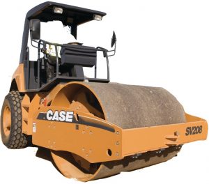
Case SV208, SV210, SV212, SV216, SV223, SV228
Complete workshop & service manual with electrical wiring diagrams for Case SV208, SV210, SV212, SV216, SV223, SV228. It’s the same service manual used by dealers that guaranteed to be fully functional and intact without any missing page.
This Case SV208, SV210, SV212, SV216, SV223, SV228 service & repair manual (including maintenance, overhaul, disassembling & assembling, adjustment, tune-up, operation, inspecting, diagnostic & troubleshooting…) is divided into different sections. Each section covers a specific component or system with detailed illustrations. A table of contents is placed at the beginning of each section. Pages are easily found by category, and each page is expandable for great detail. The printer-ready PDF documents work like a charm on all kinds of devices.
“Cre 7-29532.pdf”
Case Vibratory Rollers SV Series (SV208, SV210, SV212, SV216, SV223, SV228) Service Manual
323 pages
“47688018.pdf”
Case SV208, SV210, SV212, SV216 Tier 3 Vibratory Rollers Service Manual
442 pages
Part number 47688018; 2nd edition English; June 2014; Replaces part number 87480985NA
EXCERPT:
SECTION 41 – STEERING – CHAPTER 1
DISASSEMBLY AND ASSEMBLY OF STEERING WHEEL
Remove the steering wheel cup (6) and the nut (21) and insert tool No. 1 under the steering wheel. Remove the steering wheel using a steering wheel spanner, dismantle the steering wheel bracket (1) and slide it with the steering rod (2) out from the steering column.
Remove the snap rings (30), (31) and press shaft (2) out together with the bearing. Remove the bearing (9) from the shaft.
Press the bearing on the shaft (the bearing must be degreased and fresh grease must be applied), secure it with the snap ring (31), press it into bracket (1), secure with the snap ring (30) and mount it to the steering column.
Check that no clearance can be detected between bracket (1) and the steering column after the shaft has been set in steering. Mount the steering wheel.
…
INSTANT DOWNLOAD