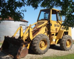
INSTANT DOWNLOAD (add to cart)
2,810 pages, bookmarked, Searchable, Printable, high quality PDF
MAKE: Case
MODEL: W14, W14H, and W14FL Articulated Loaders
W14 (Prior 9119672) Service Manual; 813 pages
W14 (After 9119672) Service Manual; 1,639 pages
9-3212: W14 (SN: 9119395-9119672) Operator’s Manual; 104 pages
9-4195: W14 (SN: Prior to 9119395) Operator’s Manual; 104 pages
9-3324: W14 (SN: W14 (9119672 & After) Operator’s Manual; 150 pages
Complete digital official shop manual contains service, maintenance, and troubleshooting information for the Case W14/W14H/W14FL Articulated Loaders. Diagnostic and repair procedures are covered in great detail to repair, maintain, rebuild, refurbish or restore your Case W14/W14H/W14FL Articulated Loaders like a professional mechanic in local service/repair workshop. This cost-effective quality manual is 100% complete and intact as should be without any missing pages. It is the same factory shop manual used by dealers that guaranteed to be fully functional to save your precious time.
This manual for Case W14/W14H/W14FL Articulated Loaders is divided into different sections. Each section covers a specific component or system and, in addition to the standard service procedures, includes disassembling, inspecting, and assembling instructions. A table of contents is placed at the beginning of each section. Pages are easily found by category, and each page is expandable for great detail. It is in the cross-platform PDF document format so that it works like a charm on all kinds of devices. You do not need to be skilled with a computer to use the manual.
EXCERPT:
Test No.5- Voltage Loss in the Negative Battery Cable
1. Do Test No.1.
2. Select the volt range of 0 to 3 volte.
3. Connect the black voltmeter lead to the negative post of the left battery.
4. Connect the red voltmeter lead to a good engine ground.
5. Push in and hold the remote starter switch.
Read the voltmeter. Release the remote starter switch.
a. If the voltmeter indication was .4 or less, the negative battery cable is good.
b. If the voltmeter indication was more than .4 volt, replace the negative battery cable.
TROUBLESHOOTING THE AUTOMATIC AUXILIARY STEERING
Your machine can have one of two designs of the electronic circuits which control the automatic auxiliary steering. Look at the relay assembly below the instrument panel on the left side of the machine. Early machines have two large capacitors, component G on page 4002-21. Late machines have one large capacitor and one large resistor, components G and M on page 4002-30.
Early Machines
Auxiliary Steering Motor
Does Not Run
See illustration on page 4002-27.
1. Start and run the engine at 1500 rpm (r/min) for one minute.
2. Stop the engine while you keep the key switch in the Run position.
3. Use a voltmeter or a 24 volt test lamp to check for electrical system voltage at point 0.
a. If there was electrical system voltage at point 0, go to step 4.
b. If there was no voltage at point 0, the cable between the starter and the auxiliary steering motor is damaged. Check the connections and replace the cable if necessary.
4. Check for electrical system voltage at point P.
a. If there was no voltage at point P, go to step 5.
b. If there was voltage at point P, the magnetic switch on the auxiliary steering motor or the auxiliary steering motor is damaged. See section 5025 to check the magnetic switch and the auxiliary steering motor.
5. There is a black wire connected to the flow switch (C). Disconnect this black wire from the bullet connector (Q). Check for voltage at the bullet connector (Q).
a. If there was voltage at the bullet connector, go to step 7.
b. If there was no voltage at the bullet connector, go to step 6.
6. Check the 5 ampere circuit breaker on the instrument panel. If you can see the red band on the button for the circuit breaker, push the button. Release the button. If you can see the red band on the button again, there is a short circuit in the electrical circuit for the auxiliary steering. Check the following items.
a. Insulation on the wires in the circuit.
b. Check the wires for the capacitors (G). Make sure that the wires for the capacitors are not in contact with the sockets for the relays or in contact with the relay bracket.
c. The 5 ampere circuit breaker is damaged. Replace the 5 ampere circuit breaker.
d. If you have not found the problem, replace the capacitors (G) and the resistor (1).
7. Connect the black wire to the bullet connector. Disconnect the red wire for the flow switch from the red-white wire at the bullet connector. Check for voltage at the red wire.
a. If there was voltage at the red wire, go to step 8.
b. If there was no voltage at the red wire, the flow switch is damaged. Replace the flow
switch.
8. Check for voltage at point R.
a. If there was voltage at point R, go to step 9.
b. If there was no voltage at point R, the relay is bad. Replace the relay.
9. Check for voltage at pointS.
a. If there was voltage at pointS, go to step 10.
b. If there was no voltage at pointS, the resistor (H) is bad. Replace the resistor.
10. Check for voltage at point T.
a. If there was voltage at point T, go to step 11.
b. If there was no voltage at point T, the relay is bad. Replace the relay.
11. Check the white-black wire between the socket and the magnetic switch on the auxiliary steering motor. If there is voltage at point T and the auxiliary steering motor still will not run, the white-black wire is damaged and must be replaced.
…

