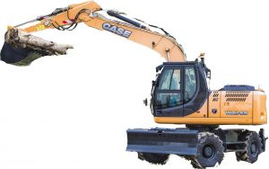
Pages from 47500167 – Case WX148 Wheeled Excavator Service Manual
Complete workshop & service manual with electrical wiring diagrams for Case WX148 Wheeled Excavator. It’s the same service manual used by dealers that guaranteed to be fully functional and intact without any missing page.
This Case WX148 Wheeled Excavator service & repair manual (including maintenance, overhaul, disassembling & assembling, adjustment, tune-up, operation, inspecting, diagnostic & troubleshooting…) is divided into different sections. Each section covers a specific component or system with detailed illustrations. A table of contents is placed at the beginning of each section. Pages are easily found by category, and each page is expandable for great detail. The printer-ready PDF documents work like a charm on all kinds of devices.
FILELIST:
47500167 – Case WX148 Wheeled Excavator Service Manual.pdf
EXCERPT:
Contents
INTRODUCTION
Engine. . .10
[10.001] Engine and crankcase . . . 10.1
[10.202] Air cleaners and lines . . 10.2
[10.206] Fuel filters . . 10.3
[10.216] Fuel tanks . . 10.4
[10.254] Intake and exhaust manifolds and muffler . . 10.5
[10.400] Engine cooling system . . . 10.6
Transmission. . .21
[21.105] Powershift transmission lubrication system . . . 21.1
[21.113] Powershift transmission . . . 21.2
[21.135] Powershift transmission external controls. . . 21.3
[21.155] Powershift transmission internal components. . 21.4
Four-Wheel Drive (4WD) system . . .23
[23.314] Drive shaft. . 23.1
Front axle system . . .25
[25.100] Powered front axle . . 25.1
[25.102] Front bevel gear set and differential . . 25.2
[25.108] Final drive hub, steering knuckles, and shafts . . . 25.3
[25.122] Axle suspension control . . . 25.4
Rear axle system. . .27
[27.100] Powered rear axle. . . 27.1
[27.106] Rear bevel gear set and differential . . . 27.2
[27.120] Planetary and final drives . . . 27.3
Brakes and controls . . .33
[33.110] Parking brake or parking lock . . . 33.1
[33.202] Hydraulic service brakes . . 33.2
Hydraulic systems. . .35
[35.000] Hydraulic systems. . . 35.1
[35.102] Pump control valves. . . 35.2
[35.106] Variable displacement pump . . . 35.3
[35.300] Reservoir, cooler, and filters. . 35.4
[35.304] Combination pump units . . 35.5
[35.352] Hydraulic swing system . . . 35.6
[35.353] Hydraulic travel system . . . 35.7
[35.354] Hydraulic central joint . . 35.8
[35.357] Pilot system . . . 35.9
[35.359] Main control valve . . . 35.10
[35.360] Hammer and rotating bucket hydraulic system . . . 35.11
[35.703] Stabilizer hydraulic system. . . 35.12
[35.730] Positioning arm hydraulic system . . . 35.13
[35.736] Boom hydraulic system . . . 35.14
[35.737] Dipper hydraulic system. . . 35.15
[35.738] Excavator and backhoe bucket hydraulic system . . 35.16
[35.741] Dozer blade cylinders . . . 35.17
Frames and ballasting . . .39
[39.103] Swing ring assembly . . . 39.1
[39.129] Stabilizers . . 39.2
[39.140] Ballasts and supports . . 39.3
Steering. . .41
[41.101] Steering control . . 41.1
[41.106] Tie rods. . 41.2
[41.200] Hydraulic control components. . . 41.3
[41.216] Cylinders . . . 41.4
Wheels. . .44
[44.511] Front wheels. . . 44.1
Cab climate control . . .50
[50.200] Air conditioning. . . 50.1
Electrical systems . . .55
[55.000] Electrical system . . . 55.1
[55.010] Fuel injection system. . . 55.2
[55.012] Engine cooling system . . . 55.3
[55.014] Engine intake and exhaust system. . . 55.4
[55.015] Engine control system. . 55.5
[55.020] Transmission speed sensors. . . 55.6
[55.031] Parking brake electrical system . . . 55.7
[55.036] Hydraulic system control . . 55.8
[55.050] Heating, Ventilation, and Air-Conditioning (HVAC) control system. . 55.9
[55.100] Harnesses and connectors. . . 55.10
[55.110] Electrical rotary joint. . 55.11
[55.302] Battery. . . 55.12
[55.404] External lighting . . . 55.13
[55.425] Boom, dipper, and bucket control system . . . 55.14
[55.512] Cab controls. . . 55.15
[55.514] Cab lighting . . . 55.16
[55.525] Cab engine controls . . 55.17
[55.530] Camera. . . 55.18
[55.640] Electronic modules . . . 55.19
Booms, dippers, and buckets . . .84
[84.100] Bucket . . . 84.1
[84.910] Boom . . . 84.2
Dozer blade and arm. . .86
[86.110] Dozer blade . . . 86.1
Platform, cab, bodywork, and decals . . .90
[90.118] Protections and footboards. . . 90.1
[90.120] Mechanically-adjusted operator seat. . 90.2
[90.150] Cab. . . 90.3
…
Hydraulic systems – Main control valve
Oil flow pump P1
The oil flows through port P1 into the main valve and then to the primary pressure-limiting valve of pump P1.
The oil flows through the two parallel channels P1 and P01 to the control spools and to the valves.
Channel P1 directs the oil flow through a valve of the bucket parallel circuit to the bucket control spool.
Channel P01 directs the oil flow to the travel spool, from where a branch-off leads to a load holding valve. The load-holding valve opens and the oil is available at the travel spool, ready to be recalled. The oil flow by-passes the stabilizer spool and reaches the boom spool. A branch-off ahead of the spool directs the oil flow also through another load holding valve to the boom spool. The oil flows then to the bucket spool. The oil is then available to the bucket spool via a load-holding valve. The oil flow reaches then the dipper spool. Also here a branch-off delivers oil to the dipper spool through a load holding valve. Two parallel channels P2 and P02 direct the oil flow through the main valve.
Oil flow pump P2
…